Newsletter | EN | 2016-10
NEWS@IMAGING October 2016 English
NEWS@IMAGING October 2016
English

You also want an ePaper? Increase the reach of your titles
YUMPU automatically turns print PDFs into web optimized ePapers that Google loves.
<strong>10</strong>/16<br />
ңң<br />
Company News<br />
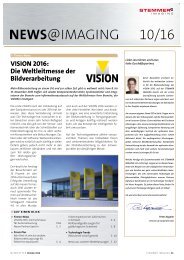
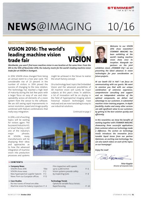
VISION <strong>2016</strong>: The world's<br />
leading machine vision<br />
trade fair<br />
Worldwide, you won't find more machine vision in one location at the same time: From the<br />
8th to the <strong>10</strong>th of November <strong>2016</strong>, the industry meets for the world's leading machine vision<br />
trade fair at VISION in Stuttgart.<br />
In 2014, VISION show changed from being<br />
an annual event to a two year cycle. The<br />
considerable rise of 23 percent in the<br />
number of visitors in 2014 proved the<br />
success of changing to the new rotation.<br />
The technology has reached a high level<br />
of maturity during the last few years with<br />
a larger focus on easy of use and interoperability<br />
across all elements of a vision<br />
system from the sensor to the software.<br />
We are still seeing rapid improvements in<br />
sensor resolution, speed and image quality<br />
combined with feature combinations that<br />
really easy integration.<br />
In <strong>2016</strong>, a lot of exciting<br />
topics will be waiting<br />
for visitors again: The<br />
buzzword Industrie 4.0,<br />
or Smart Factory, is still<br />
one of the industry's<br />
major phrases.<br />
At VISION, many<br />
manufacturers will be<br />
displaying their ideas<br />
and approaches as<br />
to how the advanced<br />
integration of machine<br />
vision into production<br />
processes and systems<br />
might be achieved in the future to realize<br />
the smart factory concept.<br />
On a technology level, topics like Embedded<br />
Vision and the advanced possibilities of<br />
3D machine vision will surely be major<br />
subjects at this year's show. In addition,<br />
a lot of innovation will be on display in<br />
the field of hyperspectral imaging where<br />
historical research technologies have<br />
matured and are now translating to easy to<br />
use industrial solutions.<br />
Continued on page 2<br />
Welcome to our VISION<br />
<strong>2016</strong> show newsletter!<br />
STEMMER IMAGING has<br />
been exhibiting at the<br />
world’s leading machine<br />
vision show since its<br />
inception. Alongside our<br />
partners on the joint<br />
exhibition stand „STEMMER City“, we are<br />
presenting the latest advances in vision<br />
technologies for your consideration on<br />
future projects.<br />
At our booth E52 in Hall 1 we focus on<br />
communicating with our guests. We want<br />
to convince you that with our unique<br />
combination of extensive experience,<br />
comprehensive consulting and support<br />
and an independent selection of the<br />
optimal components, we deliver real<br />
advantage to our customers. A substantial<br />
machine vision training program, in-depth<br />
feasibility studies and many other services<br />
can add significant value to our customers<br />
by getting to the best solution quickly and<br />
efficiently.<br />
In this newsletter, we show the benefits of<br />
working together with STEMMER IMAGING<br />
showcasing three successful applications<br />
from customer where our technology made<br />
a difference. The section on technology<br />
trends introduces the innovative focus<br />
tunable liquid lenses from our partner<br />
Optotune, an exciting new technology. You<br />
can also watch videos on each of the topics<br />
on our homepage!<br />
Enjoy the read!<br />
• CONT<strong>EN</strong>TS<br />
ңң<br />
Company News<br />
VISION show <strong>2016</strong><br />
Title<br />
VISION show news P. 2<br />
New hyperspectral supplier Specim P. 3<br />
News from our European offices P. 12<br />
ңң<br />
Case Studies<br />
No two loaves of bread are alike:<br />
Machine vision for bakery inspection P. 4<br />
Film inspection with speeds<br />
up to 1,200 m/min P. 6<br />
Vision systems provide safety<br />
by inspecting tyres P. 8<br />
Technology Trends<br />
Optotune variable focus lenses:<br />
Rapid focusing P. <strong>10</strong><br />
Peter Keppler<br />
Director of Corporate Sales<br />
NEWSLETTER October <strong>2016</strong> STEMMER IMAGING 01
ңң<br />
Company News<br />
+ + + VISION SHOW NEWS + + +<br />
Continued from page 1<br />
VISION <strong>2016</strong>: Hyperspectral,<br />
3D and other highlights<br />
This technology truly allows the<br />
visualisation of the invisible for example<br />
ripening of fruit or the chemical<br />
composition of white pills. Hyperspectral<br />
systems analyse a spectral range of <strong>10</strong>0's of<br />
wavelengths, thus opening up completely<br />
new application options beyond the<br />
current range of multi-spectral imaging<br />
applications.<br />
Hyperspectral imaging visualises the<br />
molecular structure of materials, getting<br />
to a unique „chemical fingerprint“, and<br />
enables easy and reliable identification<br />
of identical or different looking objects. In<br />
many cases, this is impossible with existing<br />
machine vision systems.<br />
Together with our partners Allied Vision,<br />
Perception Park and Specim we are<br />
presenting many interesting ideas in this<br />
exciting area of technology during this<br />
year's VISION show!<br />
In this newsletter it is impossible to publish<br />
all the current developments we and our<br />
partners will have on display during VISION<br />
<strong>2016</strong>. For that reason we invite you to<br />
attend the show, visit the news section on<br />
our web site or sign up for our e-news.<br />
+ + + VISION SHOW NEWS + + + + + + VISION SHOW NEWS + + +<br />
ңң<br />
Teledyne DALSA (booth<br />
E62) has released the<br />
new Piranha XL 8k and<br />
16k Colour TDI cameras.<br />
The first color TDI camera<br />
in machine vision,<br />
Piranha XL Color is based<br />
on Teledyne DALSA's<br />
latest CMOS technology. It delivers the best<br />
performance for color imaging with high speed,<br />
high resolution, high responsivity and low noise.<br />
Powered by Teledyne DALSA's advanced multiline<br />
CMOS color TDI technology, the Piranha XL 8k and<br />
16k Color TDI delivers a line rate of up to 70 kHz in<br />
full color mode via Camera Link HS. The Piranha<br />
XL Color family uses Teledyne DALSA’s new multiline<br />
CMOS color sensors with 4 rows for each<br />
red, green and blue color channel for 12 rows in<br />
total. TDI summing technology has demonstrated<br />
outstanding sensitivity and signal to noise ratio<br />
in high-speed color imaging in light starved<br />
conditions.<br />
ңң<br />
With uniform<br />
sensitivity in the<br />
SWIR spectrum from<br />
900 - 1700 nm, high<br />
frame rates and small<br />
pixel size, the Goldeye<br />
G-033 cameras from<br />
Allied Vision (booth F62) are ideally suited<br />
to hyperspectral imaging applications. They<br />
feature a VGA (640 x 512 pixel) high sensitivity<br />
InGaAs sensor. The sensor benefits from active<br />
thermoelectric cooling to reduce noise and<br />
enable a constant image quality. Goldeye cameras<br />
can be operated at high frame rates of up to 301<br />
fps at full resolution in 12-bit mode and capture<br />
outstanding low-noise images. Available in GigE<br />
or CameraLink versions, Goldeye cameras have<br />
the same compact and ruggedized housing<br />
(55 mm x 55 mm x 78 mm) and feature set.<br />
ңң<br />
Featuring a<br />
custom highspeed<br />
CMOS<br />
imager, JAI's<br />
new Sweep<br />
series monochrome line scan cameras push<br />
throughput to new levels of productivity. The<br />
SW-4000M-PMCL offers 4K resolution (4096<br />
pixels) and runs at up to 200,000 lines per<br />
second (200 kHz). The 7.5-micron pixels have<br />
two user-selectable well sizes - a large well for<br />
better dynamic range when ample illumination<br />
is available, and a small well for improved<br />
responsivity under more limited lighting<br />
conditions. The SW-8000M-PMCL doubles the<br />
resolution to 8192 pixels per line (8K), and is able<br />
to run at up to <strong>10</strong>0,000 lines per second (<strong>10</strong>0 kHz).<br />
Pixels are 3.75 µm x 5.78 µm in size. Both cameras<br />
feature Mini CameraLink interfaces supporting<br />
power over the interface or via a 12-pin connector,<br />
and can be ordered with either an F-mount or<br />
M42x1 lens mount. In addition, the JAI Go series<br />
keeps on growing. At Vision <strong>2016</strong>, JAI displays<br />
the latest additions to this family of small<br />
CMOS industrial cameras, the Go-2400-USB and<br />
Go-5<strong>10</strong>0-USB with USB 3.0 interfaces as well as<br />
Go-5<strong>10</strong>1-PMCL and Go-2401-PGE models.<br />
ңң<br />
Automation Technology (booth F54) launches<br />
its newest model of the successful C5 series. This<br />
3D sensor applies the laser-triangulation principle<br />
for the scanning of objects and features a<br />
resolution of 1280 x <strong>10</strong>24 pixel with measurement<br />
speeds of up to 200 kHz. It<br />
gives subpixel precision of 1/64<br />
pixel and scores a dynamic of<br />
512 height values even at its<br />
maximal profile rate of 200,000<br />
profiles per second. A distinctive<br />
feature is the independence of<br />
the measuring speed from the<br />
used evaluation algorithm.<br />
ңң<br />
The new Mitsubishi Electric<br />
CX series of high-speed<br />
Contact Image Sensors<br />
(CIS) offer a compact,<br />
distortion-free alternative<br />
to line scan<br />
cameras. The sensors<br />
allow the scanning of object surfaces<br />
distortion-free right up to the edges. With the<br />
maximum resolution of 600 dpi, they can scan<br />
surfaces at a speed of 138 metres per minute. The<br />
commonly used resolution of 300 dpi enables<br />
reliable inspection of up to 450 metres per minute,<br />
whereas the resolution of 150 dpi even allows<br />
inspection speeds of 1<strong>10</strong>0 metres per minute. The<br />
new CIS CX models are able to transfer the huge<br />
data amounts resulting from these high speeds<br />
via one or two CoaxPress interfaces depending on<br />
the sensor length.<br />
ңң<br />
The fourth generation of the successful CVS<br />
Trevista Surface, Cylinder and Multiline surface<br />
inspection systems is now available from<br />
STEMMER IMAGING. The new Trevista X4 models,<br />
also based on a patented 2.5D process called<br />
“Shape from Shading”, enable image acquisition<br />
being up to 20 % faster and with a measuring<br />
field by up to 50 % larger than before. The CVS<br />
Trevista X4 is available in all three of the previous<br />
versions as CVS Trevista Surface for the inspection<br />
of flat, stationary component<br />
surfaces, CVS Trevista Cylinder<br />
for the inspection of cylindrical<br />
shell surfaces and CVS Trevista<br />
Multiline for the examination<br />
of components in rotational or<br />
translational motion. Compared<br />
with the previous models,<br />
the X-4 generation offers<br />
illumination that is brighter<br />
by a factor of 2.5. As with the<br />
previous models in the CVS<br />
Trevista series, the new X4<br />
systems are also available from STEMMER<br />
IMAGING as complete systems.<br />
ңң<br />
The new Zeiss Interlock Compact lens family<br />
consists of four lenses: Zeiss Interlock Compact<br />
2.8/21, 2/35, 2/50 and 2.4/85. The family features a<br />
short M42x1 mount (18 mm FFD) and screws that<br />
allow exact locking of aperture and focus. The<br />
M42x1 mount offers outstanding stability. The<br />
camera lenses feature an image circle measuring<br />
43 mm and are therefore suitable for line sensors<br />
of up to 43 mm (2k - 8k) or for area scan sensors<br />
of up to 24 x 36 mm (16 - 71 Mpixels). All lenses<br />
impress with their high and unwavering image<br />
quality and precise manual focus. If needed the<br />
aperture can be continuously adjusted by taking<br />
advantage of the de-click function, allowing<br />
precise exposure setting. Their low weight and<br />
robust metal design make the lenses suitable for<br />
rough industrial use. The Zeiss Interlock Compact<br />
2.8/21 and Zeiss Interlock Compact 2.4/85 display<br />
02 STEMMER IMAGING NEWSLETTER October <strong>2016</strong>
+ + + VISION SHOW NEWS + + +<br />
excellent contrast across the entire image field<br />
whereas the Zeiss Interlock Compact 2/35 and<br />
Zeiss Interlock Compact 2/50 show extremely low<br />
distortion.<br />
ңң<br />
LMI Technologies (booth H51) announces<br />
the release of the first two models of the new<br />
Gocator 2400 series of smart 3D line profilers:<br />
Gocator 24<strong>10</strong> and 2420. These blue-laser profiling<br />
sensors are ideal for electronics and small parts<br />
inspection. They provide a high X resolution of<br />
6 µm, along with repeatable<br />
results down to 0.2 µm in<br />
height. Leveraging industryleading<br />
2-megapixel cameras<br />
and a powerful, next-generation<br />
embedded processor, Gocator<br />
24<strong>10</strong> and 2420 offers higher<br />
data density while achieving<br />
50% larger fields of view over<br />
competitors. Twice as fast as<br />
the Gocator 2300 series (400 - 5000 Hz with<br />
windowing), the sensors double the possible<br />
resolution of scan data in the direction of travel. In<br />
addition, because the sensors use a blue laser to<br />
create profiles, data around the edge of specular<br />
targets is cleaner, which is crucial for electronics<br />
and small part feature recognition.The Gocator<br />
24<strong>10</strong> and 2420 comes in a revised IP67 industrial<br />
housing offering web-based user setup, built-in<br />
3D visualization, and drag and drop measurement<br />
tools unmatched in the 3D sensor market.<br />
ңң<br />
The new LFX3 series from CCS (booth E53) has<br />
an extended lineup of sizes and colors in order to<br />
fit the growing diversity of applications and needs<br />
of the market. The newly designed housing of the<br />
LFX3 series has new mounting holes and nut slots,<br />
and with a thickness of just 13.1 mm, it is spacesaving,<br />
easy to set up and very user-friendly. In<br />
addition to the normal dot pattern, the LFX3<br />
series adds models with a line pattern, which are<br />
ideal for the inspection of irregularities on glossy<br />
or mirror-like surfaces.<br />
CCS also announces the all-new LNSP2 series<br />
of light units for line scan applications with<br />
increased light intensity of up to 900,000 lx.<br />
In addition to the standard version, the LNSP2<br />
illumination can be ordered as NDF type without<br />
a diffusion sheet. This leads to higher intensities<br />
and can be used for dark field inspection.<br />
ңң<br />
Company News<br />
STEMMER IMAGING and Specim:<br />
Hyperspectral partnership<br />
After signing a partnership agreement with the Finnish hyperspectral technology manufacturer<br />
Specim, FX series hyperspectral cameras are now available from all European subsidiaries of<br />
STEMMER IMAGING.<br />
The new FX series of hyperspectral cameras<br />
for the first time combine a very compact<br />
spectrometer, high speed sensor and<br />
integrated calibration in to a single off the<br />
shelf unit. The FX<strong>10</strong> is designed for the visible<br />
wavelength range of 400 to <strong>10</strong>00 nm and<br />
the FX16 for the SWIR wavelength range of<br />
900 to 1700 nm. By combining the required<br />
spectrograph inside the camera body using a<br />
patented process with integrated calibration<br />
and flexible sensor control the FX series<br />
delivers the most capable hyperspectral head<br />
with an extremely small footprint of only<br />
150 x 85 x 71 mm.<br />
Users of the Specim FX cameras have the<br />
option to select and evaluate from 220<br />
(FX<strong>10</strong>) or 230 (FX17) wavelengths that are<br />
optimally suited for an application due to<br />
the material properties of the test object.<br />
The number of selected wavelengths directly<br />
affects the speed of the solution: The fewer<br />
wavelengths that are selected for testing,<br />
the faster the evaluation. If a user needs e.g.<br />
all 220 wavelengths of the Specim FX<strong>10</strong>, the<br />
maximum recording speed is 330 fps. If the<br />
inclusion of only 20 wavelengths is enough<br />
to solve the application, a speed of<br />
2830 frames per second is possible,<br />
and 65<strong>10</strong> frames per second can be<br />
achieved by selecting 5 wavelengths<br />
in 3 different areas. The Specim FX17<br />
is the first InGaAs based camera<br />
that has true multi region of interest<br />
capability.<br />
Other features of the Specim FX cameras<br />
are specially adapted C-mount lenses and<br />
an excellent signal to noise ratio of 600:1.<br />
Calibration directly supplied by the Finish<br />
manufacturer guarantees identical results<br />
even if a camera module needs to be replaced<br />
due to failure or maintenance in the field.<br />
At STEMMER IMAGING, users can obtain the<br />
Specim FX hyperspectral cameras including<br />
image acquisition software and SDK and<br />
appropriate image acquisition cards and<br />
cables from a single source, which greatly<br />
simplifies the entry into hyperspectral<br />
imaging.<br />
The FX series of cameras can be used stand<br />
alone or as part of our hyperspectral systems<br />
which can learn the chemical signatures and<br />
classify each material as a unique colour<br />
then can be connected to any GigE Vision<br />
compatible machine vision software solution.<br />
ңң<br />
Silicon Software (booth C72) present the new<br />
VisualApplets 3.0 version of their development<br />
environment. New features are, amongst others,<br />
operators which represent loops in the data flow<br />
model. By this, it is possible to calculate image<br />
sequences and matchings along with image<br />
batch processing resource-saving on the FPGA<br />
for applications such as rolling average. The FFT<br />
operator has been enhanced to implement more<br />
complex filters with a high computing time<br />
such as band-pass filters resource-efficient. It is<br />
possible to use Xilinx Vivado software for the final<br />
creation of the FPGA hardware code as applets,<br />
which increases the speed of the realization in<br />
many cases.<br />
www.stemmer-imaging.com STEMMER IMAGING 03
ңң<br />
Case Study<br />
No two loaves of bread are alike<br />
The Dutch company Niverplast is one of the world's largest manufacturers of machines for<br />
inspecting bakery products. These machines are supplied all over the world and use image<br />
processing technology from STEMMER IMAGING for the reliable detection of faulty loaves of<br />
bread and bread rolls.<br />
addition, the machine recognises at this point<br />
whether there are any breakage errors or, for<br />
example, whether features like browning,<br />
topping or roundness of the bakery product<br />
is correct.<br />
After this first station, faulty products are<br />
separated out fully automatically via dynamic<br />
conveyor belts before the positively evaluated<br />
bakery products are counted at the second<br />
station. "We offer this first test cell for quality<br />
inspection as an option, but most customers<br />
order their system with both cells", says<br />
Danneberg.<br />
Subsequently, the bakery products are packed<br />
in the desired quantity according to the<br />
customer's specifications, e.g. in cartons or<br />
bags. In the system described, the customer<br />
wanted to pack the inspected bakery products<br />
in certain quantities in bags placed in cartons.<br />
Two separately controllable belts are used<br />
here for the transport of the empty and full<br />
cartons.<br />
System overview: The bakery products arrive at the left end of the machine and pass two test stations<br />
before they get packed into cardboard boxes at the right end.<br />
It all began with plastic bags: Niverplast was<br />
founded in 1986 and initially sold plastic<br />
bags, such as those offered in supermarkets<br />
for carrying home one's purchases. That soon<br />
became too little for the Dutch, however, and<br />
machines followed that could automatically<br />
open such bags, machines that could place<br />
the bags in cartons or erect cartons, and<br />
devices for welding and folding plastics.<br />
Today, Niverplast's core competence is the<br />
manufacture of complete systems with<br />
which objects can be inspected, counted and<br />
packed. Apart from plants for meat, fish, oils<br />
and greases as well as other products for the<br />
non-food segment, the company specialises<br />
in the field of bakery products.<br />
Niverplast only entered the field of bakery<br />
products in 2009, but has grown in the short<br />
time since then into one of the world's largest<br />
manufacturers of such systems. "About<br />
80 percent of our plants are conceived for<br />
industrial-size bakeries and are used all over<br />
the world", says Albert Danneberg from the<br />
Niverplast R&D team.<br />
Quality inspection and counting<br />
Danneberg describes the basic process of<br />
such a system for inspecting and counting<br />
bakery products as follows: "The pre-baked<br />
loaves or rolls can be fed to the machine in<br />
two different ways, depending on the user's<br />
wishes: we either develop an automated<br />
supply direct from the deep freezer, or the<br />
frozen dough products are manually placed<br />
on the conveyor belt. Before the products<br />
enter the machine, a metal detector first of<br />
all checks whether undesired metal parts<br />
have got into the bakery products in the<br />
preceding processes."<br />
Image processing as the core element<br />
The essential core element of the two test<br />
cells is the image processing, for which<br />
Niverplast relies fully on its long-standing<br />
partner STEMMER IMAGING. Dietmar<br />
Serbée, managing director of the Benelux<br />
branch office of STEMMER IMAGING, well<br />
remembers the start of the cooperation with<br />
Niverplast: "Initially the requirement was only<br />
to count the bakery products; the detection of<br />
errors was added later. Niverplast had already<br />
approached several other image processing<br />
companies in search of solutions, but in<br />
the end they decided to choose STEMMER<br />
IMAGING as their machine vision partner.<br />
A metal detector checks the baked goods against<br />
possible metal parts at the beginning of the<br />
process.<br />
Image processing systems play the decisive<br />
part in the steps that follow: At the first<br />
station a quality inspection takes place in<br />
which the geometrical dimensions such as<br />
the length, width and height of the bakery<br />
products are measured and analysed. In<br />
The frozen bakery products are supplied to the<br />
plant via a conveyor belt.<br />
04 STEMMER IMAGING NEWSLETTER October <strong>2016</strong>
ңң<br />
Case Study<br />
line scan cameras and the matching line scan<br />
illumination and lenses. With those we can<br />
optimally cover the conveyor belts, which are<br />
up to 1300 mm wide."<br />
Service from one single source<br />
Apart from the delivery of a few further<br />
components such as the PC systems and<br />
various cables, STEMMER IMAGING also<br />
took care of the connection of the imaging<br />
software to the graphical user interface of<br />
the system, via which amongst other things<br />
the programs for the next batch of bakery<br />
products are adjusted. "The GUI itself was<br />
developed by Niverplast. We cooperated<br />
closely on the connection in order to fully<br />
satisfy our customer's wishes", Serbée<br />
remembers.<br />
The loaves are conveyed through under a line<br />
scan illumination and a line scan camera where<br />
the images are taken.<br />
According to Serbée, the particular difficulty<br />
with the task was that no two loaves of bread<br />
are alike: "The shapes of the pre-baked loaves<br />
of bread and bread rolls are never identical.<br />
They are always slightly different. It is very<br />
difficult for an automated system to decide,<br />
for example, whether a depression in the<br />
surface of a baguette is a deliberate cut or the<br />
start of an undesired breakage."<br />
Following an intensive development phase,<br />
Serbée was able with a proprietary software<br />
solution based on the image processing library<br />
Common Vision Blox to reliably distinguish<br />
between such features. Serbée also selected<br />
the necessary hardware components for the<br />
image processing system.<br />
"In the preliminary investigations we carried<br />
out tests to determine which camera, lens<br />
and illumination could achieve optimum<br />
results. In the end we chose a combination of<br />
Danneberg is more than satisfied with<br />
his partner's service: "Niverplast has its<br />
own in-house image processing specialist,<br />
but nevertheless we are happy to rely on<br />
additional support from STEMMER IMAGING<br />
when needed." This support doesn't end after<br />
the delivery of a system either: “Whenever we<br />
need further information about new machine<br />
vision developments or technologies, we<br />
know whom to contact!”<br />
Good development<br />
The largest system that Niverplast has<br />
developed and delivered so far encompasses<br />
two parallel lines, each with test cells based<br />
Depending on the width of the conveyor belt, one<br />
or two lines scan cameras are used.<br />
on image processing for the quality inspection<br />
and counting of bakery products.<br />
Despite the very good order book situation,<br />
the developers at Niverplast have further<br />
ideas that will be incorporated into the<br />
design of future systems. Danneberg reveals<br />
one of these ideas: "The height of bakery<br />
products can be measured using a multiple<br />
3D triangulation system. Loaves of bread and<br />
bread rolls can thus be measured even more<br />
accurately and defects in the bakery products<br />
can be recognised more reliably, therefore we<br />
will be offering this possibility as a further<br />
option for our systems."<br />
• WATCH VIDEO<br />
This video tells more<br />
details about the<br />
Niverplast machine:<br />
The setup for the next bakery products is made<br />
via a touch panel at the machine.<br />
At the end of the line the inspected bakery<br />
products are placed in cartons.<br />
• BACKGROUND INFORMATION<br />
Niverplast (www.niverplast.com) develops innovative<br />
packaging solutions to protect and transport<br />
a wide range of products. Bread, meat, fish, liquids<br />
and non-food products that have to be packed in<br />
a bag and box are the core business of the Dutch<br />
company, whose systems are in use on every<br />
continent in the world.<br />
www.stemmer-imaging.com STEMMER IMAGING 05
ңң<br />
Case Study<br />
Real time film inspection with<br />
speeds up to 1,200 m/min<br />
Witten-based OCS GmbH is one of the world’s leading manufacturers of productionintegrated<br />
film inspection systems. Up to ten cameras operate side by side in scalable systems<br />
enabling production speeds of up to 1,200 metres per minute. Machine vision components<br />
from STEMMER IMAGING make up the optical solution.<br />
includes up to ten cameras operating side<br />
by side. In practice, most applications use<br />
systems with two cameras for the inspection<br />
of film widths ranging from 1500 mm to 2000<br />
mm.<br />
In addition to the line scan camera’s sensor<br />
size of up to 8192 pixels (8k) the camera<br />
distance defines the attainable resolution.<br />
For example, films for the packaging industry<br />
generally do not require resolutions over 150<br />
μm to 200 μm, which corresponds with the<br />
use of one camera per metre of film width.<br />
Technical films are inspected from double to<br />
triple the resolution and therefore require a<br />
greater number of cameras.<br />
The mere number of pixels is not the<br />
measure of all things. The sensor elements<br />
in 8k cameras are smaller and consequently<br />
less light-sensitive. In the case of less lightpermeable<br />
material you would be more likely<br />
to opt for a 4k camera with a larger sensor<br />
diameter. This simple consideration shows<br />
that plant engineers must bring along a great<br />
deal of experience in order to optimally meet<br />
the technical requirements and minimise the<br />
costs.<br />
OCS inspection system in the Witten-based demo centre.<br />
Plastic films can be found in a wide variety<br />
of different thicknesses and colours –<br />
transparent or opaque, structured or coated<br />
– in almost all industries and areas of life.<br />
Applications range from flat screens, cell<br />
phone displays, pharmaceutical tablet<br />
blisters, food packaging to baby diapers.<br />
Films are produced in huge plants 24/7,<br />
around the globe. Their quality depends on<br />
many parameters. Quality monitoring and<br />
quality assurance during production have<br />
a significant impact on the end product’s<br />
quality. There are a variety of standards: the<br />
specific requirements are agreed individually<br />
between manufacturers and users. Type and<br />
number of permissible errors are reflected in<br />
the production costs and, consequently, in the<br />
prices for the end users.<br />
„In simple terms: nobody likes to spot sealed<br />
insects in packaged cheese; there shouldn’t<br />
be any turbidities on TFT screens, and you<br />
definitely do not want to find any holes in the<br />
insulation of high-voltage cables,” exemplifies<br />
Mendo Gusevski. He is a product manager at<br />
OCS, short form for Optocal Control Systems,<br />
a company which specialises in the optical<br />
quality assurance of polymers and the films<br />
produced from them.<br />
The measurement range of defects in<br />
extruded films mostly depends on their<br />
intended use. For example, packaging film<br />
(PET) requires reliable detection of defect sizes<br />
between 150 μm and 500 μm. In technical film<br />
the defect sizes range from 50 to 200 μm. In<br />
surface protection film they range from 60<br />
μm to 160 μm, and in film with specific optical<br />
characteristics it may be necessary to reliably<br />
detect defects ranging from 25 μm to <strong>10</strong>0 μm.<br />
Defects occur during the extrusion process<br />
due to incorrectly melted material (so-called<br />
specks or burn marks), fisheye, thin places,<br />
holes, streaks, flow lines or simply dirt.<br />
Whether quality monitoring should classify<br />
inhomogeneities as defects depends on<br />
the subsequent use of the film. It would be<br />
impossible to detect all these defects at the<br />
required speed without the use of machine<br />
vision.<br />
Over the years of working together with<br />
STEMMER IMAGING, OCS have developed a<br />
scalable, modular inspection system, which<br />
Each camera with its own frame grabber<br />
In order to manage the amounts of image<br />
data resulting from real time production<br />
speeds of up to 1,200 metres per minute,<br />
each camera is equipped with its own frame<br />
grabber. Camera and frame grabber are both<br />
included in a common housing attached to<br />
the machine. These work stations offer the<br />
necessary modularity and short signalling<br />
pathways between camera and frame<br />
grabber. Integrated cooling fans generate a<br />
slight overpressure to prevent the deposition<br />
of production-related dust on the lens. In<br />
Special Truecolor illumination with controllable<br />
LED elements allows the setting of different<br />
colours and the use of near-infrared light if<br />
required.<br />
06 STEMMER IMAGING NEWSLETTER October <strong>2016</strong>
ңң<br />
Case Study<br />
class," explains Georg Schelle. "Basically, we<br />
deliver a modular platform for OCS solutions<br />
across all machine vision elements, which can<br />
be adapted to specific applications."<br />
OCS in-house test and training centre<br />
A front bar illumination (in this example,<br />
with blue light colour) ensures optimal light<br />
conditions.<br />
harsh and extremely dirty environments,<br />
hermetically sealed housings are used,<br />
which are then cooled by a separate dust and<br />
moisture purge air circuit.<br />
OCS and STEMMER IMAGING have agreed on<br />
a number of internal standards for cameras,<br />
cabling and illumination. The collaboration<br />
led to special firmware versions regarding<br />
JAI and Teledyne Dalsa cameras as well as<br />
Teledyne Dalsa frame grabbers successfully<br />
delivering around 90 % of the applications.<br />
Pre-assembled modules<br />
STEMMER IMAGING has long left their role<br />
as pure component distributor: „In order<br />
to better support our key customers we<br />
have built up profound expertise in the preassembly<br />
of modules “, explains Georg Schelle,<br />
Senior Key Account Manager at STEMMER<br />
IMAGING, who has been supporting OCS<br />
for many years. „These modules save our<br />
customers a lot of integration time compared<br />
to individual components. Especially for OCS<br />
we are working with highly complex optical<br />
modules with Qioptiq lenses and filters from<br />
Schneider Kreuznach or Midwest Optical<br />
Systems. Our clients benefit from shorter<br />
delivery times, higher operational safety and<br />
reduced cost.“<br />
The LED lines lights for OCS with lengths<br />
ranging from <strong>10</strong>0 to 3,600 mm are now<br />
manufactured by STEMMER IMAGING<br />
supplier CCS in Japan. Today's design is based<br />
on a proven standard product line, that has<br />
continuously been improved over the years.<br />
"This is reflected in a number of characteristics:<br />
for example, the homogeneity of the LED<br />
light output, the diffuser properties in all<br />
three axes, the concept of connectors and<br />
maintenance as well as the IP54 protection<br />
A rewinder located in OCS’s in-house test and<br />
training centre is available for pre-testing the<br />
equipment of a planned system. Sample film<br />
material can be verified under real conditions<br />
at speeds of up to 400 m/min and system<br />
designs can be optimised according to the<br />
customer’s needs.<br />
OCS are constantly testing new technologies<br />
with this system, such as a specific Truecolour<br />
illumination with controllable LED elements<br />
which allow the setting of different colours<br />
and, if necessary, even the use of near infrared<br />
light. The Mitsubishi Electric Contact Imaging<br />
Sensors, innovative polarisation cameras as<br />
well as the uncooled Teledyne Dalsa Calibir<br />
LWIR thermography cameras have all been<br />
tested with this system.<br />
„We normally use traditional monochrome<br />
line scan cameras in our systems”, explains<br />
OCS expert Gusevski. „For special applications<br />
we use JAI cameras with three sensor lines<br />
and an RGB prism.“<br />
However, the possibilities of a machine<br />
builder like OCS are constantly growing with<br />
new, innovative technologies. This is why<br />
OCS always thinks outside the box in order to<br />
find new technologies for future systems at<br />
an early stage. Here again, working together<br />
with STEMMER IMAGING pays off for us“,<br />
Gusevski emphasises.<br />
Inspection for process control<br />
In the current OCS systems all errors are<br />
recorded as individual images, which can<br />
be evaluated retrospectively. The analysis<br />
software developed by OCS allows operating<br />
personnel the use of different kinds of error<br />
trends, which help derive alarms and specific<br />
modifications of process parameters in the<br />
production process.<br />
Trend data show tendencies as a result<br />
of modifications. This way, problems can<br />
easily be detected whether it is with certain<br />
additives fed, with extraordinary dirt ingress<br />
or when changing the pellet tanks, and can<br />
then be allocated to certain sections. The<br />
defective film sections can then be cut out in<br />
subsequent commissioning processes.<br />
Oliver Hissmann, Sales Manager at OCS, explains<br />
the function of a film inspection system.<br />
A few years ago the QS management was<br />
satisfied with an inspection rate of <strong>10</strong>%<br />
the web width. Today, as computing power<br />
constantly increases, there is a growing<br />
demand for <strong>10</strong>0% inspection which can be<br />
reliably provided by OCS.<br />
„Currently the widest web section we are able<br />
to inspect with our FSP 600 system at the<br />
speed of 1,200 m/min, is 870 cm wide. This<br />
enormous amount of data, which sums up to<br />
400 MByte per camera, can only be handled<br />
on a hardware level. For that reason and if<br />
necessary, we talk directly with Teledyne<br />
Dalsa developers about details that do not<br />
affect other users with less time-critical<br />
processes”, explains Oliver Hissmann, Sales<br />
Manager at OCS. „The highest resolution<br />
required by a customer is currently 25 µm at<br />
a web width of 1,500 mm. This is solved with<br />
ten synchronised cameras.“<br />
• WATCH VIDEO<br />
Watch our short video<br />
about the OCS film<br />
inspection system:<br />
• BACKGROUND INFORMATION<br />
OCS Optical Control Systems GmbH (www.ocsgmbh.<br />
com) based in Witten, Germany, offers individual<br />
complete solutions in the areas of raw material and<br />
web inspection as well as turn-key laboratories to<br />
many international customers.<br />
www.stemmer-imaging.com STEMMER IMAGING 07
ңң<br />
Case Study<br />
For safely rolling tyres<br />
Every day the lives of millions of people depend on intact tyres on cars and airplanes. The<br />
Zeiss Optotechnik tyre inspection systems equipped with STEMMER IMAGING’s state-of-theart<br />
machine vision components provide the maximum possible safety in this domain.<br />
direct phase measurement with only one<br />
shearing image. In addition to tyre testing,<br />
shearography is used for non-destructive<br />
testing of composites.<br />
Over 1,000 measuring heads worldwide<br />
Intact systems are used worldwide by all<br />
well-known tyre manufacturers as well<br />
as by a large number of medium-sized<br />
retreading companies. A total of more than<br />
1,000 measuring heads have already been<br />
installed, including licensed systems with<br />
Zeiss measuring heads.<br />
For inspecting the treads the measuring heads are automatically lowered into the tyre.<br />
Carl Zeiss Optotechnik GmbH generates<br />
about one third of their annual sales with<br />
systems for the non-destructive inspection<br />
of tyres. The company, which has been known<br />
as Steinbichler Optotechnik GmbH until 2015,<br />
is one of the world’s leading suppliers in<br />
this segment and has already implemented<br />
inspection systems for tyres with diameters<br />
of up to 4300 mm. Such enormous tyres are<br />
used in huge mining vehicles, but also new<br />
and retreaded pneumatic tyres of passenger<br />
cars, trucks, aircraft, motorcycles. Even the<br />
racing tyres of all current Formula 1 teams are<br />
tested for defects by these systems.<br />
The company’s „Intact“ tyre inspection<br />
systems are based on shearography, an<br />
optical measurement technology which<br />
has established itself as the standard in<br />
the automotive sector, in aviation it is even<br />
required by law.<br />
Intact measuring device with four measuring<br />
heads each at an angle of 90 degrees.<br />
Shearography is an interferometric testing<br />
method that is able to detect even the smallest<br />
defects with a size of only a few microns<br />
on stressed components. The test object is<br />
illuminated with a laser light and inspected<br />
by a CCD camera with a so called shearing<br />
lens. These lenses project the object image<br />
onto the camera chip twice; each object point<br />
is thus represented twice which results in an<br />
interferogram. When the test object deforms<br />
under load, the laser light, reflected by the<br />
component, changes. Due to superposition of<br />
an image in its unloaded state, the recording<br />
under load means the changes of each point<br />
in the image can be detected.<br />
When testing tyres the required load is<br />
generated by varying the ambient pressure.<br />
Between the first and second recording the<br />
pressure is lowered by about 50 mbar. Any<br />
air bubbles enclosed in the tyre expand as a<br />
result of the negative pressure and slightly<br />
deform the surface of the tyre at the weak<br />
points. Conclusions on defect type and size<br />
can be drawn by comparing and evaluating<br />
the resultant images.<br />
„We have been working with shearography<br />
technologies since around 1990“, explains<br />
Rainer Huber, NDT product manager at Carl<br />
Zeiss Optotechnik who is responsible for<br />
the tyre testing system developments. His<br />
company holds several relevant patents,<br />
such as one for the spatial phase shift, the<br />
„Our goal is one hundred percent safety – the<br />
failure of a tyre in operation or when being<br />
inflated can have fatal consequences“, says<br />
Huber. In the testing process the tyre tread<br />
and the side walls are examined for internal<br />
detachments and air inclusions, which would<br />
not be visible by a human. „When testing<br />
retreaded truck tyres experience shows that<br />
about 20 percent of the visually impeccable<br />
used tyres are classified unsafe when applying<br />
shearography“, Huber points out. The use of<br />
shearography is also cost-effective, especially<br />
in the area of retreading. The customers<br />
benefit from cost savings in production and<br />
purchasing.<br />
Positioning of the measuring heads for side wall<br />
inspection<br />
The Intact systems are characterised by their<br />
non-contact and non-destructive application.<br />
Since there is no need for preparation of<br />
the tyre surface the application is simple,<br />
fast and cost-effective: After loading the<br />
pressure-tight test chamber the measuring<br />
heads are precisely placed inside the tyre to<br />
record the tread from the inside thanks to the<br />
automated detection of the tyre size. Each<br />
of the four measuring heads inspects two<br />
sectors of 45 degrees.<br />
In the second step the measuring heads are<br />
automatically positioned on the outside to<br />
inspect the side wall on top. Finally, the tyres<br />
08 STEMMER IMAGING NEWSLETTER October <strong>2016</strong>
ңң<br />
Case Study<br />
been working with STEMMER IMAGING on all<br />
aspects of machine vision for many years."<br />
Rainer Huber, NTD Product Manager at Carl Zeiss<br />
Optotechnik, in front of an Intact system with<br />
tyre flipper.<br />
are flipped for the final examination of the<br />
second side wall. „Thanks to the automated<br />
process we are able to achieve cycle times<br />
below one minute for a complete tyre test”,<br />
says Huber.<br />
Machine vision is the base<br />
Machine vision is the technical base of the<br />
tyre testing systems: Each measuring device<br />
consists of four measuring heads, each<br />
containing a camera with a corresponding<br />
lens. Since the 90s, the company – at that time<br />
still operating under the name Steinbichler<br />
Optotechnik GmbH – has been dealing with<br />
machine vision and has developed extensive<br />
know-how in this field.<br />
For almost that long, they have been<br />
successfully working with STEMMER<br />
IMAGING, who supplies cameras and other<br />
optical and electromechanical components.<br />
„Our clients expect reliable machines in<br />
order to be successful in their markets.<br />
This is exactly what Carl Zeiss Optotechnik<br />
is able to guarantee on the basis of many<br />
years of experience“, explains Huber. „It is<br />
very important for us that every component<br />
is supplied by a reliable partner with the<br />
appropriate know-how and the right range of<br />
product and services. For this reason, we have<br />
Shearography detect errors in the micron range<br />
So it is no surprise that he and his team<br />
again relied on their proven machine vision<br />
technology partner when developing a new<br />
system generation. The starting point for the<br />
innovation was the desire for standardisation,<br />
according to Huber: „A multitude of different<br />
measuring heads have been developed over<br />
time. In the future, we wanted to use only one<br />
single type for different applications.“<br />
A great challenge was reducing the size of<br />
the measuring devices to allow the testing of<br />
even smaller tyre diameters. So far, the limit<br />
has been 16-inch-tyres due to the footprint of<br />
the measuring heads. Now the goal was, to be<br />
able to inspect even 12-inch-tyres. However,<br />
the concept of having up to four measuring<br />
heads per device should remain the same;<br />
the simple formula was: the more measuring<br />
heads, the shorter the measuring time,<br />
the higher the throughput. However, the<br />
necessary downscaling of the measurement<br />
device could not be achieved geometrically<br />
with the Allied Vision standard cameras that<br />
had been used so far.<br />
Camera modification as key to success<br />
A substantial redesign was necessary, at the<br />
same time continuity was required: Carl Zeiss<br />
Optotechnik had been using the monochrome<br />
Allied Vision Prosilica GC1380 cameras for<br />
years. These cameras are equipped with<br />
a Sony ICX285 CCD sensor providing a<br />
resolution of 1388 x <strong>10</strong>38 pixels. This sensor is<br />
especially designed for infrared applications<br />
and is ideally suited for this application when<br />
being combined with the optics Zeiss had<br />
developed for shearography measurement.<br />
For the redesign Carl Zeiss Optotechnik opted<br />
for a high-speed version of the previously<br />
used Prosilica camera with the same CCD<br />
sensor: The Allied Vision Manta G145B-30fps<br />
with a frame rate of up to 30 fps is now<br />
being used. Due to the discontinuation of the<br />
built-in Sony CCD sensor by the year 2020,<br />
Huber does not expect any major problems:<br />
"Since Allied Vision also offers a mechanically<br />
identical CMOS camera, easy exchangeability<br />
of the cameras is guaranteed."<br />
More headaches were caused by a mechanical<br />
problem: the standard version of the selected<br />
Manta cameras including cabling was too long<br />
to inspect 12-inch tyres with four measuring<br />
heads contained in one measurement device.<br />
The Allied Vision Manta camera – left: integrated<br />
in the standard housing, right: modified version<br />
for Carl Zeiss Optotechnik<br />
„This problem could be successfully solved<br />
through a special modification by STEMMER<br />
IMAGING’s hardware development“, praises<br />
Huber: „In close cooperation with our<br />
mechanical design department, these experts<br />
developed a housing variant in which the<br />
cable connections are arranged at an angle of<br />
90 degrees to the image layer and not linear<br />
as in the case of the standard housing." That<br />
way, the length of each Manta camera could<br />
be reduced from 80 to 64 mm – and thus met<br />
the geometrical needs for the inspection of<br />
12-inch tyres.<br />
Further customer-specific services at<br />
STEMMER IMAGING, like aperture presetting<br />
and the sealing of all screws on every<br />
individual lens, or the selection and longterm<br />
tests of cables helped Carl Zeiss<br />
Optotechnik keeping their new Intact tyre<br />
inspection system generation at a constant<br />
high level, proving their daily use worldwide<br />
in development and production.<br />
• WATCH VIDEO<br />
This video explains the<br />
modifications and the<br />
tyre inspection system:<br />
• BACKGROUND INFORMATION<br />
More than 25 years of experience and competence<br />
in optical measurement and sensor technology have<br />
written the success story of Carl Zeiss Optotechnik<br />
GmbH (http://optotechnik.zeiss.com/). Since 1987,<br />
the company has been developing high-precision<br />
optical measurement systems and corresponding<br />
software solutions, which are used in a wide range<br />
of application areas.<br />
www.stemmer-imaging.com STEMMER IMAGING 09
ңң<br />
Technology Trends<br />
Brought into focus at<br />
lightning speed<br />
Variable focal length lenses enable rapid focusing in image-processing applications where<br />
the working distance between the object and the camera system is frequently changing.<br />
A current-controlled actuator presses fluid through a ring from the outside into the interior of the lens,<br />
thus altering the curvature of the lens and hence its focal length.<br />
Particularly during the mass manufacture<br />
of products, the working distance between<br />
an object and a camera system generally<br />
changes little or not at all. In these cases the<br />
optical design of a vision system is easy: the<br />
prevailing working distance and the desired<br />
resolution are used to calculate the optical<br />
characteristics of the system which, after<br />
the selection of suitable components and<br />
integration into the installation, performs<br />
its function without any further adaptation.<br />
While conversion of the installation to<br />
products with a different geometry only<br />
requires a one-time adaptation of the vision<br />
system until the next change.<br />
In contrast to this, in many applications vision<br />
systems must deal with frequent changes<br />
in the working distance. In an extreme case,<br />
the distance between the inspection plane<br />
and the camera system can change from one<br />
object to the next, which can best be seen in<br />
the example of a system for reading addresses<br />
on packages: the heights of such packages<br />
can vary continually. In order to be certain of<br />
capturing the desired information in focus,<br />
in this example the working distance to the<br />
vision system or the focus of the optics would<br />
have to be adjusted for each package, which<br />
often is not achievable with the necessary<br />
speed using mechanical means.<br />
mechanical guides, which limit not only the<br />
overall size and the response time, but also<br />
the robustness and life of any solution.<br />
Variable lens curvature<br />
Variable focal length lenses provide an<br />
interesting alternative for such applications.<br />
The technical basis of this is the variable<br />
curvature of a lens which consists of a<br />
membrane filled with fluid. If the pressure<br />
within the lens is altered, the curvature can<br />
be adjusted (see Figure 1). A change to the<br />
lens radius of a few micrometres can achieve<br />
the same optical effect as the mechanical<br />
displacement of a lens by several centimetres.<br />
Optical systems can thus be designed to be<br />
more compact, often with fewer lenses and<br />
without any translational movement.<br />
Swiss company Optotune specialises in the<br />
development of such variable focal length<br />
lenses. The company controls the electro-<br />
optical components by means of a control<br />
current from an electromagnetic actuator.<br />
The change in refractive power (measured in<br />
dioptres) is a linear function of the impressed<br />
current, is reproducible and free of hysteresis.<br />
The relationship between refractive power<br />
and current will vary from lens to lens due to<br />
production tolerances, and even temperature<br />
fluctuations affect the control. To enable<br />
accurate control of the refractive power,<br />
Optotune lenses use a temperature sensor<br />
with calibration data for the particular lens<br />
stored. In combination with a current driver, an<br />
absolute accuracy of typically 0.1 dioptres can<br />
be achieved. Communication with the driver<br />
takes place via a USB connection and a serial<br />
protocol which can be implemented in various<br />
programming languages. The source code for<br />
the controller is available in C# and Labview.<br />
An alternative current driver with GigE, RS232<br />
and analogue interfaces is available from<br />
Gardasoft. To simplify system integration<br />
for the user, Optotune is collaborating with<br />
various camera and software manufacturers<br />
with a view to implementing integrated<br />
autofocus functions.<br />
Fast and robust<br />
Liquid lenses offer a range of other advantages.<br />
They dispense completely with expensive<br />
mechanical drives and furthermore enable<br />
a more robust design that can work with<br />
higher precision than mechanically based<br />
optics solutions. While mechanical autofocus<br />
systems often reach their limits with respect<br />
to speed and reliability, variable focal length<br />
lenses enable focusing over large changes in<br />
working distance within milliseconds (see<br />
Figure 3) and guarantee billions of cycles.<br />
Furthermore they can be completely sealed<br />
so that no dust can enter, thus reducing the<br />
susceptibility to errors during image capture<br />
and subsequent evaluation.<br />
While traditional optical systems enable<br />
focusing within certain limits according to<br />
the required distance, one or more lenses<br />
have to be moved along the optical axis<br />
to achieve this. This requires motors and<br />
Control of the variable focal length lens: a USB-based current driver enables accurate control of<br />
refractive power by reading calibration data and temperature from the lens.<br />
<strong>10</strong> STEMMER IMAGING NEWSLETTER October <strong>2016</strong>
ңң<br />
Technology Trends<br />
is also increasing against the background of<br />
Industry 4.0: Anyone wanting to manufacture<br />
small batches down to a quantity of 1 must<br />
equip his production with solutions that<br />
can react quickly and flexibly to changing<br />
geometries of the inspected parts.<br />
Difference between optics with fixed focal length<br />
(left) and variable focus optics.<br />
Another interesting feature of variable focal<br />
length lenses is that various optical materials<br />
can be used. A liquid with low dispersion<br />
with a refractive index of 1.300 and an<br />
Abbe number of <strong>10</strong>0 is particularly suitable<br />
for polychromatic imaging optics. There is<br />
practically no chromatic aberration.<br />
For this reason, variable focal length lenses<br />
can also be combined with standard objective<br />
lenses to produce high quality autofocus<br />
systems without having to take additional<br />
measures for colour correction.<br />
Application examples<br />
A rapid change of working distance and<br />
resultant frequent focusing are becoming<br />
necessary more often in many applications.<br />
The importance of variable focal length lenses<br />
• CHROMATIC ABERRATION<br />
Chromatic aberrations (colour deviations) are image<br />
defects that arise due to the different focal points for<br />
different colours. White light is composed of various<br />
colours or wavelengths. When white light impinges<br />
on a lens, each colour takes a slightly different path.<br />
This is called dispersion. If a lens is not designed<br />
to correct this dispersion, colour fringes appear on<br />
every exposure. Exact measurements are therefore<br />
not possible, as the edges of the inspected object<br />
appear out of focus. The degree of this blurring<br />
increases towards the edge of the picture. As can be<br />
seen on the following figure, the effects of chromatic<br />
aberration become visible as colour fringes at the<br />
edges of the objects.<br />
There are already many examples where<br />
Optotune electro-optical components are in<br />
use. One of the most obvious applications of<br />
variable focal length lenses is the reading of<br />
2-D codes on, among other things, objects of<br />
differing sizes in the logistics, pharmaceutical<br />
or automotive sectors. While 1-D codes can<br />
be scanned with a laser, reading 2-D codes<br />
requires a camera.<br />
This opens up additional inspection and<br />
measurement functions. Here, variable focal<br />
length lenses enable a significant expansion<br />
of the working range, e.g., from infinity down<br />
to a few mm. In a typical optical set-up, the<br />
variable focal length lens is mounted directly<br />
in front of an objective lens with a fixed focal<br />
length.<br />
Lens control principles<br />
There are various control principles: If the<br />
distance to the object is known by the system,<br />
the working distance can be controlled<br />
directly in an open control loop where the<br />
lens is set to the corresponding focal length.<br />
The distance information can be provided by<br />
a suitable sensor or via programming. In this<br />
mode, focus setting times of 5 to 15 ms are<br />
possible.<br />
If the distance is not known, the lens can<br />
also be operated in an oscillatory mode. At<br />
low frequencies of e.g. 5 Hz, several images,<br />
each with different working distances, can<br />
be captured until a code has been read<br />
successfully. While this approach is not<br />
particularly fast, it is simple to implement<br />
and can be used without calibration.<br />
At high frequencies (up to some <strong>10</strong>0s of Hz) it<br />
is possible to tune through the entire working<br />
range during the shutter time. The result<br />
is an image with extended depth of field,<br />
albeit with reduced contrast as the individual<br />
“images” with different focus superimpose<br />
during the shutter time. Nevertheless, codes<br />
with good contrast can readily be recognised.<br />
The applications where Optotune lenses have<br />
proved to be a very suitable resource also<br />
include the inspection of optical components<br />
with several surfaces such as camera lenses<br />
The Optotune Model EL-16-40 installed between<br />
camera and objective lens<br />
for mobile phones, or counting particles in a<br />
3-dimensional fluid volume.<br />
In applications that require a high<br />
magnification, the variable focal length lens<br />
is generally placed between the objective<br />
lens and the tube lens. The achievable z-range<br />
thus depends on the magnification factor. A<br />
typical system achieves a z-range of 16 mm<br />
with a magnification of 5x. If the variable<br />
focal length lens is operated by a 12-bit<br />
current source which permits 4096 steps, an<br />
axial resolution of 4 µm can be achieved.<br />
Part of a complete system<br />
STEMMER IMAGING has been selling<br />
Optotune variable focal length lenses already<br />
for some time now. In combination with all<br />
the other components required, including<br />
suitable lighting, optics and cameras, the<br />
Gardasoft current driver as well as auxiliary<br />
services such as feasibility studies or support<br />
in designing systems, we thus provide<br />
everything from a single source to simplify<br />
the use of this technology.<br />
Thanks to the increasing availability of<br />
electronics and software, the integration of<br />
variable focal length lenses is easier today<br />
than ever before.<br />
• WATCH VIDEO<br />
We have prepared a<br />
video to explain the<br />
Optotune technology:<br />
www.stemmer-imaging.com STEMMER IMAGING 11
www.stemmer-imaging.com<br />
ңң<br />
Company News<br />
News from STEMMER IMAGING<br />
across Europe<br />
STEMMER IMAGING now has 13 offices in eleven European countries. Here we inform you about<br />
current local activities and news in these offices.<br />
• EV<strong>EN</strong>TS<br />
■■<br />
8 th - <strong>10</strong> th November <strong>2016</strong><br />
VISION, Stuttgart, Germany<br />
International Trade Fair for<br />
Machine Vision and Identification<br />
Technologies<br />
Hall 1, Booth E52<br />
UNITED KINGDOM ▹ The colleagues<br />
from our UK office have won the prestigious<br />
award for the ‘Most Innovative Vision Project’<br />
at the PPMA (Processing and Packaging<br />
Machinery Association) Group Awards<br />
announced at the end of September. The<br />
winning project was for the supply and<br />
integration of 25 cameras on the Bloodhound<br />
Supersonic Car. This project is a British<br />
endeavour to build a jet and rocket powered<br />
vehicle capable of reaching <strong>10</strong>00 mph, for<br />
a new world land speed record attempt. 25<br />
cameras are located at strategic points on<br />
the car, e.g. to deliver live streamed video for<br />
broadcast purposes or to look at the output<br />
from the rocket and jet engine exhausts.<br />
Other cameras monitor critical engineering<br />
parameters such as the wheel-ground<br />
interface. In-cockpit cameras monitor controls<br />
and driver actions. In making the award, the<br />
judges commented: “The STEMMER IMAGING<br />
project demonstrates ground-breaking<br />
innovation. It is a complex undertaking,<br />
involving several aspects of machine vision<br />
technology from optics through to data<br />
handling.”<br />
GERMANY ▹ We have already been asked<br />
about the dates of our next technology forum<br />
series. The next tour will start in Germany on<br />
the 17th and 18th of October 2017. Dates and<br />
venues for the the other offices and countries<br />
are not yet fixed, but we will of course keep<br />
you informed in time.<br />
FINLAND ▹ In order to give our customers<br />
better service, the STEMMER IMAGING office<br />
in Finland is moving to new modern premises.<br />
The new office is situated in a striking modern<br />
building in Espoo's Keilaniemi dynamic<br />
business district in Greater Helsinki. The area<br />
is characterized by technology and innovation<br />
• TRAININGS<br />
STEMMER IMAGING runs free regular training<br />
sessions on different machine vision topics in our<br />
European Imaging Academy training suites. These<br />
trainings cover topics like:<br />
■■<br />
Introduction to machine vision<br />
■■<br />
Lighting & lenses technology<br />
■■<br />
Common Vision Blox<br />
■■<br />
Sherlock machine vision application suite<br />
■■<br />
Machine vision solutions from Teledyne DALSA<br />
■■<br />
Hyperspectral imaging<br />
■■<br />
3D image processing with the LMI Gocator<br />
STEMMER IMAGING offers these training courses in<br />
several of our offices in different countries.<br />
For information on events, training and courses,<br />
please visit our homepage!<br />
with many corporate headquarters, hi-tech<br />
industries and startups. One of Keilaniemi's<br />
major draws is its close proximity to the<br />
university region of Otaniemi and the easy<br />
access to public transport and road routes.<br />
SWITZERLAND ▹ A well-attended technology<br />
day focusing on the subject of 3D<br />
image processing was carried out by our<br />
office in Switzerland in September. After an<br />
introduction into the basics on this topic, LMI<br />
as a company and their the sensor platform<br />
have been introduced. Successful application<br />
examples with different models of the LMI<br />
Gocator series as well as a presentation of<br />
current trevista systems for surface testing<br />
completed the day.<br />
D<strong>EN</strong>MARK ▹ The Danish office move<br />
within the city of Copenhagen has been<br />
completed.<br />
• CONTACT<br />
HEAD OFFICE<br />
GERMANY . AUSTRIA<br />
Phone: +49 89 80902-0<br />
info@stemmer-imaging.de<br />
FRANCE<br />
Phone: +33 1 45069560<br />
info@stemmer-imaging.fr<br />
D<strong>EN</strong>MARK<br />
Phone: +45 33 73 00 00<br />
info@stemmer-imaging.dk<br />
POLAND<br />
Phone: +48 664 921 922<br />
info@stemmer-imaging.pl<br />
FINLAND . BALTICS<br />
Phone: +358 9 43 555 00<br />
info@stemmer-imaging.fi<br />
SWED<strong>EN</strong> . NORWAY . ICELAND<br />
Phone: +46 8 555 1<strong>10</strong> 00<br />
info@stemmer-imaging.se<br />
IMAGING<br />
IS OUR<br />
PASSION.<br />
SWITZERLAND<br />
LIECHT<strong>EN</strong>STEIN<br />
Phone: +41 55 415 90 90<br />
info@stemmer-imaging.ch<br />
THE NETHERLANDS<br />
BELGIUM . LUXEMBOURG<br />
Phone: +31 575 798888<br />
info@stemmer-imaging.nl<br />
UNITED KINGDOM<br />
IRELAND<br />
Phone: +44 1252 780000<br />
info@stemmer-imaging.co.uk<br />
Find us on:<br />
12 STEMMER IMAGING www.stemmer-imaging.com