

review
aS45307enPA
aS45307enPA

Create successful ePaper yourself
Turn your PDF publications into a flip-book with our unique Google optimized e-Paper software.
W<br />
ABB 4 |16<br />
<strong>review</strong><br />
en<br />
Charging a bus in 15 seconds 8<br />
A long tradition in electric railways 16<br />
World’s longest rail tunnel 35<br />
Remote service at sea 44<br />
The corporate<br />
technical journal<br />
Transportation
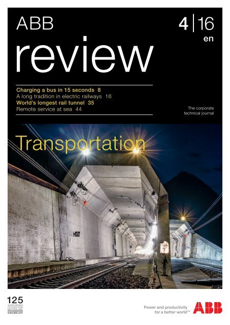
Transportation and its infrastructure form one of the<br />
more visible and tangible applications of technology.<br />
The front cover shows the portal of the Gotthard base<br />
tunnel, which opened this year. The present page shows<br />
the TOSA electric bus. Both projects are discussed in<br />
articles in the present issue of ABB Review.<br />
2 ABB <strong>review</strong> 4|16
Contents<br />
Transportation<br />
focus<br />
Event<br />
Simulation<br />
Switching<br />
and safety<br />
Up-time and<br />
productivity<br />
Index<br />
6<br />
8<br />
13<br />
16<br />
25<br />
30<br />
35<br />
40<br />
44<br />
50<br />
51<br />
57<br />
63<br />
67<br />
72<br />
79<br />
84<br />
90<br />
Cities take charge<br />
Making the case for the electrification of urban public transportation<br />
Charged in a flash<br />
Optimization of batteries for a flash-charged bus<br />
Green park<br />
Krka national park, Croatia, is the first national park in the world to install<br />
ABB Terra 53 fast DC/AC chargers<br />
Electrifying history<br />
A long tradition in electric railway engineering<br />
Weight loss program<br />
ABB’s Effilight ® traction transformer delivers less weight and losses and needs<br />
up to 70 percent less oil<br />
Efficiency that climbs mountains<br />
Cutting the energy consumption of the Allegra trains<br />
Peak power<br />
ABB’s ZX0 medium-voltage switchgear and PMA cable protection for the<br />
Gotthard Base Tunnel<br />
Record breaker<br />
ABB to provide power, propulsion and automation for the world’s most<br />
advanced port icebreaker<br />
Improving remote marine service<br />
A concept for the next generation ABB customer and service portal<br />
Connect. Collaborate. Outperform<br />
Automation & Power World returns to Houston in March 2017<br />
Loss prophet<br />
Predicting stray losses in power transformers and optimization<br />
of tank shielding using FEM<br />
Wind protection<br />
Low-voltage switching and protection strategies in wind turbines<br />
Arc angel<br />
Arc flash prevention measures increase safety<br />
Switching the subject<br />
A look at recent advances in IGCT technologies for high-power electronics<br />
Grid4EU<br />
Laying the groundwork for the development of tomorrow’s electricity grids<br />
Cloud robotics<br />
Smart robots leverage the Internet of Things, Services and People from<br />
edge to cloud<br />
A combined future<br />
Microgrids with renewable power integration<br />
2016 Index<br />
The year at a glance<br />
Contents<br />
3
Editorial<br />
Transportation<br />
Bazmi Husain<br />
Dear Reader,<br />
The portion of the world’s population living<br />
in cities is forecast to rise from 54 percent<br />
in 2014 to 66 percent by 2050. The relent -<br />
less growth of urban centers is bringing with<br />
it numerous societal and environmental<br />
challenges. Not least among these is that<br />
of transportation. With both urban populations<br />
and their affluence on the rise, more<br />
and more vehicles are competing for limited<br />
road space while contributing to pollution.<br />
On a local level, emissions from vehicles can<br />
have a detrimental impact on both human<br />
health and quality of life. On a global level,<br />
transportation contributes to about one<br />
quarter of global anthropogenic emissions<br />
of carbon dioxide. Governments are increasingly<br />
recognizing these challenges and<br />
implementing measures to make transportation<br />
greener.<br />
Besides pollution, transportation is also linked<br />
to congestion. Further to its nuisance aspect,<br />
congestion is an economic liability as people<br />
spend time unproductively and the delivery of<br />
goods is disrupted.<br />
For example, ABB is also at the forefront<br />
of the digitalization that enables assets and<br />
systems to share data, perform more effectively<br />
and be serviced and diagnosed remotely.<br />
Further areas that the company is perhaps<br />
less commonly associated with include marine<br />
transportation, service offerings and the charging<br />
of electric vehicles. The latter category<br />
includes the “flash charging” of electric<br />
buses. This technology involves automatically<br />
connecting and topping up a bus’s batteries<br />
at intermediate points along its route, thereby<br />
reducing the weight of batteries and thus<br />
making the system more economically competitive.<br />
Following a successful test operation,<br />
ABB recently signed a contract to deliver<br />
the world’s first commercial “flash-charged”<br />
bus project to the Swiss city of Geneva.<br />
I trust this issue of ABB Review will raise your<br />
awareness of and kindle your interest in the<br />
challenges of electric transportation and<br />
highlight ABB’s involvement in its ongoing<br />
development.<br />
Fortunately, there are many ways to meet<br />
these challenges, ranging from hybrid or<br />
electric cars to high-capacity metros.<br />
The electrification and energy efficiency<br />
aspects of such developments are core<br />
elements of ABB’s portfolio, but the company’s<br />
abilities are far from limited to these.<br />
Bazmi Husain<br />
Chief Technology Officer<br />
ABB Group<br />
4<br />
ABB <strong>review</strong> 4|16
Editorial<br />
5
Cities take charge<br />
Making the case<br />
for the electrification<br />
of urban public<br />
transportation<br />
TIMOTHY PATEY, RETO FLUECKIGER, ALESSANDRO ZANARINI, JAN POLAND,<br />
DAVID SEGBERS, PHILIPPE NOISETTE, BRUCE WARNER – The sustainable<br />
development of cities is pivotal for the Earth˚s future. The UN forecasts the<br />
percentage of people living in cities will rise from 54 percent in 2014 to<br />
66 percent in 2050, [1]. During the same period, global population is forecast<br />
to reach 9.7 billion. And this population will place demands on mobility.<br />
Urban transport is already a cause of congestion and pollution today. Only<br />
an increased emphasis on sustainability in transport infrastructure can ensure<br />
tomorrow’s cities safeguard their ecology, economy, and quality of life.<br />
6 ABB <strong>review</strong> 4|16
sions standards for particulate matter<br />
from 0.648 g/km in 1992 (Euro I) to<br />
0.018 g/km in 2013 (Euro VI) for transit<br />
vehicles [6]. This trend has improved air<br />
quality over the past 20 years, and will<br />
continue to do so in the years to come.<br />
But if public transportation is ever to<br />
achieve zero local emissions of particulate<br />
matter, full electrification of the system<br />
is needed.<br />
Moving back to the global perspective,<br />
such a drive for full electrification of public<br />
transportation will at the same time<br />
contribute to climate change mitigation<br />
(assuming the power grid is powered<br />
with a significant portion of renewable<br />
power in its mix).<br />
Using TOSA technology, diesel-powered<br />
bus fleets can be replaced with electric<br />
bus fleets, without the need to install<br />
overhead lines. The technology is realizable<br />
today, as has been demonstrated in<br />
the city of Geneva.<br />
TOSA is just one example of what ABB<br />
has to offer. The company provides electrification<br />
of public transportation systems;<br />
both on-board the vehicles and off-board<br />
at the charging infrastructure. Increased<br />
electrification, in whatever form, is key to<br />
reducing emissions and achieving carbon<br />
neutrality in all modes of transportation.<br />
Many examples of this are presented<br />
in the present issue of ABB Review.<br />
Today, transportation contributes<br />
nearly one quarter of global<br />
CO 2<br />
emissions [2]. Climate<br />
change mitigation is being driven<br />
by treaties including the Kyoto Protocol<br />
(1997), the Copenhagen Accord<br />
(2009), and the Paris Agreement (2016).<br />
Policy makers have agreed that the average<br />
global temperature rise should not<br />
exceed 2°C above the average global<br />
temperature of pre-industrial times [3].<br />
It has been postulated that in order to<br />
assure a 50 percent probability of global<br />
warming below this limit by the end of<br />
the 21st century, the CO 2<br />
emissions between<br />
2011 and 2050 have to be limited<br />
to 1,100 gigatons [4].<br />
The challenge is huge. The potential atmospheric<br />
CO 2<br />
emissions from the combustion<br />
of existing fossil fuel reserves would<br />
outweigh this limit by a factor of more<br />
than three [5]. Climate change mitigation<br />
policies are urgently required.<br />
On a local level, the desire of many cities<br />
for cleaner air is also motivating change.<br />
The European Union has promoted<br />
cleaner air in cities by tightening emis-<br />
Title picture<br />
Electrification of transportation systems contributes<br />
both to clean air in cities and to reducing carbon<br />
emissions.<br />
This combined drive for carbon neutrality<br />
and clean air becomes increasingly pressing<br />
with advances in urbanization and<br />
population as well as traffic challenges.<br />
Rather than building only highways, cities<br />
are increasingly developing metros,<br />
trams and electric buses.<br />
TOSA future<br />
The city of Geneva, Switzerland, has taken<br />
a key step towards full electrification<br />
of their public transportation network. The<br />
“TOSA” bus line which is presently being<br />
delivered is fully electric despite not featuring<br />
overhead lines. “Flash” or opportunity<br />
charging [7] is used to top up the<br />
batteries at intermediate points on the<br />
route, meaning the dead weight of large<br />
batteries can be reduced, saving on both<br />
space and weight. Also, charging time is<br />
reduced at the ends of the route, which<br />
is especially important during time-constrained<br />
rush-hour operation. The flash<br />
charging is done safely in only 15–20 s,<br />
during the time that the bus is stopped<br />
anyway to allow passengers to embark<br />
and disembark.<br />
The absence of overhead lines is not only<br />
less visually disruptive, but also saves on<br />
installation costs by avoiding extensive<br />
construction work for the overhead line<br />
and allows for more flexible bus operations<br />
during road works. It also saves on<br />
maintenance, which accounts for a significant<br />
portion of the costs of traditional<br />
bus operation using overhead line infrastructure.<br />
The TOSA bus and in particular<br />
its batteries are discussed in the next<br />
article of this edition of ABB Review.<br />
Timothy Patey<br />
Reto Flueckiger<br />
Jan Poland<br />
Alessandro Zanarini<br />
ABB Corporate Research<br />
Baden-Daettwil, Switzerland<br />
timothy.patey@ch.abb.com<br />
reto.flueckiger@ch.abb.com<br />
jan.poland@ch.abb.com<br />
alessandro.zanarini@ch.abb.com<br />
David Segbers<br />
ABB Discrete Automation & Motion<br />
Turgi, Switzerland<br />
david.segbers@ch.abb.com<br />
Philippe Noisette<br />
Bruce Warner<br />
Power Grids<br />
Geneva, Switzerland<br />
philippe.noisette@ch.abb.com<br />
bruce.warner@ch.abb.com<br />
References<br />
[1] World Population Prospects, 2014, United<br />
Nations.<br />
[2] Transport, Energy and CO 2<br />
: Moving toward<br />
Sustainability, 2009, International Energy Agency.<br />
[3] United Nations Framework Convention on<br />
Climate Change (UNFCC) Report of the Con fer -<br />
ence of the Parties on its Fifteenth Session, held<br />
in Copenhagen from 7 to 19 December 2009.<br />
Part Two: Action taken by the Conference of the<br />
Parties at its Fifteenth Session. United Nations<br />
Climate Change Conf. Report 43, 2009.<br />
[4] Meinshausen, M., et al., Greenhouse-gas<br />
emission targets for limiting global warming to<br />
2°C. Nature, 2009. 458(7242): p. 1158–1162.<br />
[5] McGlade, C. and P. Ekins, The geographical<br />
distribution of fossil fuels unused when limiting<br />
global warming to 2 [deg]C. Nature, 2015.<br />
517(7533): p. 187–190.<br />
[6] Exhaust emissions of transit buses, 2015,<br />
EMBARQ.<br />
[7] TOSA (Trolleybus Optimisation Systeme<br />
Alimentation) 2013. 2016.<br />
Cities take charge<br />
7
Charged in a flash<br />
Optimization of batteries for a flash-charged bus<br />
TIMOTHY PATEY, RETO FLUECKIGER, JAN POLAND, DAVID SEGBERS, STEFAN WICKI –<br />
With its six trolleybus and four tram lines, transportation in the Swiss city of<br />
Geneva already makes extensive use of electric traction. As a further step<br />
towards making its public transportation system carbon-neutral, the city has<br />
announced it will replace the diesel buses used on line 23 by a battery-powered<br />
electric bus fleet.<br />
8 ABB <strong>review</strong> 4|16
64 ABB <strong>review</strong> 4|13<br />
BRUCE WARNER, OLIVIER AUGÉ, ANDREAS MOGLESTUE – If you thought that charging<br />
electric vehicles was all about fiddling with charger cables followed by long and unproductive<br />
waits, then think again. ABB has (together with partners) developed an electric<br />
bus that not only automatically charges in 15 s, but also provides high transportation<br />
capacity and energy efficiency. The bus connects to an overhead high-power charging<br />
contact when it pulls into a stop and tops up its batteries during the time its passengers<br />
are embarking and disembarking. Besides being an attractive means of transportation,<br />
the TOSA bus that is presently running in the Swiss city of Geneva also has numerous<br />
environmental bonuses. It is silent, entirely emissions free, uses long-life and small<br />
batteries while the visual clutter of overhead lines and pylons that is often a barrier<br />
to trolleybus acceptance is made a thing of the past. The system is inherently safe<br />
because the overhead connectors are only energized when they are engaged, and the<br />
electromagnetic fields associated with inductive charging concepts are avoided. Such<br />
has been the success of the demonstrator that the concept is now being developed for<br />
series production. Let the future begin.<br />
he world is becoming increasingly<br />
urban. In 2008, for the first<br />
time in the history of humanity,<br />
more than half the planet’s<br />
population lived in cities. Cities bring<br />
with them many challenges, not least of<br />
which is the efficient organization of<br />
transportation. To avert gridlock and<br />
reduce pollution, planners across the<br />
globe are encouraging the use of public<br />
transportation.<br />
Public transportation in cities can take<br />
numerous forms, but what they all have<br />
in common is that they require energy to<br />
be transmitted from a fixed supply to a<br />
moving vehicle. Some particular solu-<br />
Title picture<br />
The TOSA demonstration bus is presently running in<br />
public service in Geneva.<br />
tions aside, this transmission takes one reduced acceptability of noise and pollution<br />
have led manufacturers and opera-<br />
of two forms: Power is either stored<br />
on the vehicle (usually in the form of tors to think about alternatives to diesel<br />
diesel fuel, as on a<br />
bus) or transmitted<br />
electrically (requiring<br />
a continuous<br />
contact system as<br />
on metros, trams<br />
and trolleybuses).<br />
The latter forms of<br />
transportation are typically seen on heavily<br />
used corridors where the significant mented to varying degrees include less<br />
for powering buses ➔ 1. Solutions imple-<br />
infrastructural investment is easier to conventional fuels (such as natural gas)<br />
justify. The former solution is typical for and adopting alternative propulsion concepts,<br />
for example hybrid buses, battery<br />
more lightly patronized corridors where<br />
lower startup costs permit routes to be buses and trolleybuses. A feature shared<br />
created or modified more flexibly. by the latter three is that they use electric<br />
motors, permitting energy to be recovered<br />
when the bus brakes, creating an<br />
This status quo has held its own for<br />
many decades, but how much longer opportunity to reduce energy wastage.<br />
can it do so? Rising fuel prices and the Recovering energy is not, however,<br />
Taking charge 65<br />
1 TOSA<br />
ABB Review 4/2013 featured an article on the<br />
TOSA bus demonstration in the Swiss city of<br />
Geneva.<br />
Taking charge<br />
Flash charging<br />
is just the<br />
ticket for clean<br />
transportation<br />
T<br />
Recovering energy when<br />
the bus brakes helps reduce<br />
wastage.<br />
Following a successful conclusion of the<br />
demonstration, Geneva’s public transportation<br />
operator, TPG, decided to convert its<br />
route 23 to the mode. The order for 12 TOSA<br />
buses and 13 charging stations was<br />
confirmed in July 2016. ABB’s scope of<br />
delivery includes converters, motors and the<br />
charging stations.<br />
2 Bus stop with flash charging station. The bus’ batteries receive a 15 second 600 kW<br />
boost while at the stop.<br />
ABB was recently awarded orders<br />
totaling more than $16<br />
million by Geneva’s public<br />
transport operator, Transports<br />
Publics Genevois (TPG), to provide flash<br />
charging and on-board electric vehicle<br />
technology for 12 TOSA (Trolleybus Optimisation<br />
Système Alimentation) fully electric<br />
buses ➔ 1. Their operation can save<br />
as much as 1,000 tons of carbon dioxide<br />
per year (compared with the existing<br />
diesel buses).<br />
ABB will deliver and deploy 13 flashcharging<br />
stations along the route ➔ 2, as<br />
well as three terminal and four depot<br />
feeding stations. The flash-charging connection<br />
technology used will be the<br />
world’s fastest: It will take less than one<br />
second to connect the bus to the charging<br />
point. The onboard batteries can<br />
then be charged by a 600 kW boost lasting<br />
15 seconds using time that the bus is<br />
at the bus stop anyway. A further four to<br />
five minute charge at the terminus will<br />
enable a full recharge of the batteries.<br />
Title picture<br />
Geneva (Switzerland) is to replace a presently diesel<br />
operated bus line by flash-charged battery buses.<br />
In this view the bus is receiving its 15 second top<br />
up charge at a flash charging station similar to that<br />
which will be installed at 13 intermediate stops of<br />
route 23.<br />
ABB will deliver and deploy<br />
13 flash-charging stations<br />
along the route, as well as<br />
three terminal and four depot<br />
feeding stations.<br />
ABB solutions for the electrification<br />
of public transportation<br />
ABB has developed a modular platform<br />
for the electric drive train of city buses<br />
➔ 3. This caters to all e-bus applications<br />
ranging from the traditional trolleybus<br />
to DC fast-charged or flash-charged<br />
battery buses. At the heart of this are<br />
ABB’s highly efficient water-cooled permanent-magnet<br />
traction motors as well<br />
as the extremely compact BORDLINE<br />
CC200 ➔ 4 traction<br />
and auxiliary converter.<br />
The converter<br />
can drive up to<br />
two traction motors<br />
and all the auxiliary<br />
consumers of the<br />
bus.<br />
On a flash-charged<br />
bus, the converter<br />
also handles the flash and opportunity<br />
charging at bus stops and the DC fastcharging<br />
at the end of the line. On an<br />
electric trolleybus, it is supplemented by a<br />
double-insulated DC-DC input converter.<br />
Adding a battery to this drive train enables<br />
the bus to operate free of catenary<br />
lines (overhead lines).<br />
Charged in a flash<br />
9
3 Key technology components of the TOSA bus.<br />
4 ABB’s BORDLINE CC200 traction an auxillary converter.<br />
Fully automatic<br />
energy transfer<br />
system<br />
Water-cooled<br />
battery pack<br />
Water-cooled<br />
traction converter<br />
Two-axle drive powered by<br />
water-cooled traction motors<br />
As every mobile<br />
phone user knows,<br />
availability of<br />
battery power is<br />
essential if the<br />
device is to fulfil<br />
its function.<br />
5 Physical and chemical degradation mechanisms of graphite within a<br />
Li-ion battery 1 .<br />
Graphene layer<br />
SEI<br />
Li +<br />
Donor solvent<br />
H +<br />
Mn 2+<br />
Graphite exfoliation, cracking<br />
(gas formation, solvent co-intercalation)<br />
Electrolyte decomposition and SEI formation<br />
SEI conversion, stabilization and growth<br />
SEI dissolution, precipitation<br />
Positive / negative interactions<br />
Lithium plating and subsequent corrosion<br />
SEI is the solid electrolyte interphase formed as a consequent of electrolyte decomposition and<br />
related side reactions.<br />
Charging matters<br />
As every mobile phone users know,<br />
availability of battery power is essential if<br />
the device is to fulfil its function. The<br />
same applies to an electric bus or tram.<br />
However, after a certain time and usage,<br />
a battery needs to be replaced. A challenge<br />
for ABB engineers is to predict<br />
when this will occur, and to create specifications<br />
that ensure availability of power<br />
through the product and system’s life.<br />
A model informed by experiments<br />
A battery “dies” because it fails to deliver<br />
the power required for the specified<br />
timespan. More specifically, the decline<br />
in capacity (Ah) and rise in internal resistance<br />
(Ω) are simultaneous processes<br />
that compromise the battery’s ability<br />
to deliver power. This is due to chemical<br />
and mechanical decomposition of<br />
the materials inside the battery (exam-<br />
ple of graphite degradation are shown<br />
in ➔ 5).<br />
A key challenge in battery integration lies<br />
in predicting the rate at which the battery<br />
will degrade. One approach is to test the<br />
batteries: The batteries are charged and<br />
discharged under various conditions to<br />
quantify the decline in capacity and rise<br />
in resistance. However, this method<br />
alone cannot cover all the use cases of<br />
the electric bus. There are too many variables,<br />
including temperature, state of<br />
charge, depth of discharge / charge, and<br />
current. The time and sheer number of<br />
experiments required to cover all the use<br />
cases is simply too high.<br />
The solution to estimating battery lifetime<br />
is to make a model informed by experimental<br />
results and a fundamental understanding<br />
of the key physical and chemi-<br />
cal processes of the battery. This approach<br />
is semi-empirical, in that it relies partly on<br />
empirical/experimental results. Models<br />
based purely on physics are not suitable<br />
as the high number and complexity of<br />
the various physical and chemical interactions<br />
are too numerous to run computations<br />
efficiently. It is more time efficient<br />
to conduct a series of well-designed experiments<br />
and use the results to create a<br />
model. The key to building a good model<br />
is to design the right experiments.<br />
Step 1: Design the right experiments<br />
In this phase, the temperatures, depth of<br />
discharge, state of charge, and current<br />
are varied in a series of battery tests. The<br />
Footnote<br />
1 Vetter, J., et al., Ageing mechanisms in<br />
lithium-ion batteries. Journal of Power Sources,<br />
2005. 147(1–2): p. 269-281.<br />
10 ABB <strong>review</strong> 4|16
6 Simple representation of an electrical, thermal, aging model of a Li-ion battery<br />
Load<br />
(kW) &<br />
temperature<br />
(°C)<br />
Electrical<br />
Cell temperature<br />
Losses<br />
Thermal<br />
∆Q, ∆IR<br />
SoC profile<br />
Aging<br />
Cell temperature<br />
Voltage,<br />
capacity, and<br />
temperature<br />
over lifetime<br />
The key to building<br />
a good model is<br />
to design the right<br />
experiments.<br />
Key operation concept is the interplay of variables between models: e.g. change in capacity (∆Q)<br />
and internal resistance (∆IR) modify the electrical model, which varies the state of charge (SoC)<br />
profile that modifies the aging model.<br />
7 Example of a battery load profile for one return trip of a 12km route with 13 flash charging<br />
and 2 terminal charging sections<br />
Power (kW)<br />
500<br />
300<br />
100<br />
-300<br />
-300<br />
0 1 2 3 4 5 6<br />
Time (s)<br />
A key challenge in battery<br />
integration is predicting<br />
the rate at which the battery<br />
will degrade.<br />
capacity decline and resistance rise are<br />
measured. This will later enable a prediction<br />
of how certain charge/discharge<br />
events of the battery would impact the<br />
battery aging over time and use.<br />
Step 2:<br />
Develop an electric, thermal, aging model<br />
The internal electrical architecture of a<br />
Li-ion battery is complex, but electrical<br />
response is approximated with a number<br />
of resistive and capacitive components.<br />
Heat and age modify these components, as<br />
informed by the thermal and aging models.<br />
As electric buses are power applications,<br />
Joule heating (i 2 R) is the dominant type<br />
of energy loss and dictates the battery<br />
cell’s wall and core temperatures during<br />
operation. These<br />
temperatures are<br />
essential for accurate<br />
electrical and<br />
aging models.<br />
The aging model<br />
is based on the<br />
results of experiments,<br />
and quantification of the decline<br />
in capacity and rise in resistance expected<br />
from the many possible charge / discharge<br />
events.<br />
The resulting battery model combines<br />
the electric, thermal, and aging submodels.<br />
The interplay of these sub-models<br />
enables the prediction of the change<br />
in capacity and resistance under a given<br />
load and temperature over time ➔ 6.<br />
Step 3: Verify the model<br />
Experiments at cell level inform and verify<br />
the model using realistic load profiles.<br />
This is an iterative process involving further<br />
refinement.<br />
Step 4: Apply the model<br />
Once the model has been generated and<br />
verified, it becomes an important tool in<br />
scenario analysis. The battery’s temperature,<br />
voltage, energy, and peak power all<br />
affect how a battery system should be<br />
dimensioned. While this process is not<br />
the final say in how big a battery should be,<br />
modelling informs decision makers and<br />
designers on how key variations in battery<br />
size and cooling influence bus performance.<br />
Scenario analysis<br />
The following scenario analysis considers<br />
a 25 ton articulated bus with a maximum<br />
passenger capacity of 80 people. There<br />
are 13 flash charging stations distributed<br />
along the route of 12 km length, providing<br />
a charging power of 600 kW for 20 seconds.<br />
The terminal charging uses 400 kW<br />
and takes four to five minutes. A typical<br />
load profile of such a bus is shown in ➔ 7.<br />
Key battery requirements for this electric<br />
bus include:<br />
– 10 year lifetime<br />
– minimum charge voltage of 600 V (to<br />
assure sufficient power is available for<br />
the motor and auxiliary systems and<br />
to match the charging infrastructure)<br />
– cell temperature of max. 60 °C (to<br />
ensure safe operation, as the electrolyte<br />
evaporates above 80 °C)<br />
– charging power of 600 kW for 20s<br />
(to allow for rapid charges), and<br />
400 kW for 5 minutes<br />
– an energy of 46 kWh (to complete a<br />
journey in one direction, with backup<br />
power for exceptional circumstances).<br />
Parameters for three configuration scenarios<br />
are presented in ➔ 8.<br />
Charged in a flash<br />
11
8 Overview of three possible battery designs for a 12 km urban route (with flash charging)<br />
Design criteria “Small energy” “Strong cooling” “Large energy”<br />
Cell chemistry LTO LTO LTO<br />
Max. C-rate permitted (continuous) 6 6 6<br />
Max. C-rate permitted (for 20s) 8 8 8<br />
Cells in series / in parallel 314 / 4 314 / 4 375 / 4<br />
Energy content [kWh] 58 58 69<br />
Minimum voltage [V] 630 630 750<br />
Nominal cont. power [kW] 400 400 480<br />
Nominal 20s power [kW] 580 580 690<br />
Battery weight incl. cooling system [kg] ~1600 ~1600 ~2000<br />
Coolant temperature [°C] 25°C 15°C (active) 25°C<br />
C-rate is the rate at which a battery discharges, with 1 C-rate equal to a complete discharge in<br />
1 hour, and 10 C-rate 1/10th of 1 h, (ie, 6 minutes).<br />
9 Overview of the model calculation for the three possible battery designs for a 12 km urban<br />
route (with flash charging). BOL = beginning of life, EOL = end of life<br />
Use of the battery model on these three<br />
battery cases is a simple means to demonstrate<br />
battery design impact on maintaining<br />
a reliable system performance at<br />
end of life. Further design iterations<br />
would be done to find the optimum solution,<br />
while mitigating all risks through<br />
system analysis.<br />
Furthermore, the battery model informs<br />
the public transportation operator on the<br />
battery design impact of choosing flash<br />
charging or terminal charging. The bus<br />
line operators know their cities and its<br />
needs, and are in the best position to decide<br />
whether terminal or flash charging is<br />
most suited. The battery model is a support<br />
tool to inform them of the battery<br />
design consequences of their system<br />
choices.<br />
“Small Energy” “Strong Cooling” “Large Energy”<br />
BOL EOL BOL EOL BOL EOL<br />
EOL - 6 y - 12 y - 10 y<br />
Capacity 100% 83% 100% 80% 100% 80<br />
Resistance 100% 200% 100% 170% 100% 185%<br />
Energy content 58 kWh 48 kWh 58 kWh 46 kWh 69 kWh 55 kWh<br />
Voltage range 690 - 850 V 590 - 850 V 690 - 850 V 630 - 850 V 840 - 1010 V 770 - 1010 V<br />
C-rate terminal (continuous) 5.3 6.2 5.3 6 5.4 5.6<br />
C-rate flash (for 20 s) 8 8.5 8 8.3 6.8 7<br />
Peak core cell temperature 57 °C 86 °C 43 °C 58 °C 44 °C 57 °C<br />
Battery efficiency 90% 80% 90% 85% 92% 86%<br />
The three battery scenarios were analyzed<br />
using the thermal, electric and aging<br />
battery model to forecast the lifetime<br />
and the end of life (EOL) properties. Here<br />
the EOL is defined as 80 percent of the<br />
initial capacity or 200 percent of the initial<br />
resistance. The results of the model<br />
analysis shown in ➔ 8.<br />
For the case of the “small energy” battery,<br />
flash charging the battery at 600 kW<br />
would not be possible at end of life as it<br />
is beyond the power limit of the battery<br />
pack (with a C-rate limit of 8). It would<br />
be able to power the bus for some time<br />
using terminal charging only, but the<br />
rise in resistance would be too great<br />
(210 percent), resulting in an eventual<br />
unsafe temperature (T > 80°C, internal to<br />
the cell) and as well as minimum voltage<br />
of less than 600 V, which is insufficient to<br />
power the motor and auxiliary systems.<br />
For the case of the “strong cooling” battery,<br />
the battery would be fine for terminal<br />
charging only. However the flash<br />
charging of 580 kW is beyond the limits<br />
of the battery pack. The lower coolant<br />
temperature, however, is sufficient to<br />
maintain healthy voltage and temperature<br />
ranges throughout the battery’s lifetime<br />
of 12 years. This is a clear demonstration<br />
that battery temperature matters<br />
for system lifetime performance.<br />
The “large energy” battery is the only one<br />
of the three considered that could fulfill<br />
both the flash-charging and terminal<br />
charging requirements. For flash-charging,<br />
the additional cells in series is simply<br />
needed to raise the voltage and lower<br />
the current to meet the power requirements<br />
thronghout the battery’s life. Additionally,<br />
this configuration (375s4p) would<br />
ensure healthy temperature window for<br />
the entire 10 years of the required battery<br />
life.<br />
Timothy Patey<br />
Reto Flueckiger<br />
Jan Poland<br />
ABB Corporate Research<br />
Baden-Daettwil, Switzerland<br />
timothy.patey@ch.abb.com<br />
reto.flueckiger@ch.abb.com<br />
jan.poland@ch.abb.com<br />
David Segbers<br />
Stefan Wicki<br />
Discrete Automation & Motoion<br />
Turgi, Switzerland<br />
david.segbers@ch.abb.com<br />
stefan.wicki@ch.abb.com<br />
12 ABB <strong>review</strong> 4|16
Green park<br />
Krka National Park, Croatia, is the first national park in<br />
the world to install ABB Terra 53 fast DC/AC chargers<br />
ALEKSANDAR RADOSAVLJEVIC, MERSIHA VELIC HAJDARHODZIC,<br />
MICHELLE KIENER – Krka National Park, situated in Šibenik-<br />
Knin county in Croatia, is a world famous natural phenomenon<br />
with its seven waterfalls of the Krka River. On the park’s<br />
territory there are many historical and cultural monuments,<br />
one of them is the remains of the hydro power plant Jaruga,<br />
the oldest power generating facility in the world, built in 1895.<br />
That was the first alternating current (AC) power system in<br />
Croatia, the first in Europe and the second in the world,<br />
coming online only two days after the Niagara Falls AC plant.<br />
To protect its nature and heritage Krka National Park has<br />
invested in five electric vehicles and four ABB DC electric<br />
vehicle fast-charging stations: Terra 53 CJG. The first unit is<br />
already installed and it is operating every day at Lozovac,<br />
nearby the town of Šibenik and the hydro plant Jaruga.<br />
Green park<br />
13
1 ABB’s Terra 53 CJG charging station at Lozovac<br />
Krka National Park (Krka NP) is<br />
home to numerous endemic<br />
plants, geomorphological forms<br />
of rocks and animal species<br />
and covers a total area of 109 km 2 . It is<br />
challenging to maintain and preserve<br />
natural rarities and therefore the park<br />
managers undertake constant efforts in<br />
order to keep the high level of conservation<br />
of these natural treasures. One aspect<br />
of this work has been the initiative<br />
to use electric and hybrid plug-in vehicles<br />
within the park and to provide fast<br />
DC charging stations. The first charging<br />
station is already in operation in Lozovac<br />
➔ 1. The next charging station will be<br />
installed as part of the new information<br />
center at Laškovica above Roški slap<br />
and the remaining stations will be strategically<br />
placed at a variety of loca tions<br />
within the park.<br />
An even greener park<br />
The missions of Krka NP include reducing<br />
CO 2<br />
emissions, as well as reducing<br />
noise, fuel consumption and maintenance<br />
costs. To invite all park visitors to<br />
be part of the efforts to protect the environment,<br />
the charging stations will be<br />
available for all visitors with electric cars.<br />
Title picture<br />
Krka National Park lies within Šibenik-Knin County,<br />
and covers a total area of 109 km²<br />
The stations are set to charge two cars<br />
at the same time and charging lasts for a<br />
duration of 0.5 to 1.5 hours, depending<br />
on the capacity of the vehicle battery.<br />
The ABB chargers are equipped with internet<br />
based connected services and allow<br />
users to easily connect to different software<br />
systems and payment platforms. The<br />
connectivity also enables remote monitoring,<br />
maintenance and functionality add-ons.<br />
The working temperature of the charging<br />
stations is from – 35 °C to + 50 °C.<br />
Green line<br />
The initiative is part of the “Green Line”<br />
program, launched by the Ministry of Environmental<br />
and Nature Protection and<br />
The electric vehicle charging<br />
infrastructure is a Terra DC 53<br />
multi-standard 50 kW modular<br />
station with one, two or three<br />
plugs for the rapid charging of<br />
electric vehicles.<br />
the Environmental Protection and Energy<br />
Efficiency Fund which is intended for<br />
public institutes managing protected<br />
areas, national parks and nature parks.<br />
“This is a step forward in nature conservation,<br />
and we are particularly proud that the<br />
Public Institution of Krka National Park<br />
joined the Green Line project, which provides<br />
protected areas the opportunity to<br />
serve as a model for the introduction and<br />
broader user of electric vehicles. We hope<br />
that the project will continue to develop, to<br />
allow greater numbers of citizens to become<br />
direct contributors to environmental<br />
protection through the purchase of electric<br />
vehicles,” stressed Krešimir Šakic´, director<br />
of the Public Institution of Krka NP.<br />
The electric vehicle charging infrastructure<br />
is a Terra DC 53 multi-standard 50 kW<br />
modular station with one, two or three<br />
plugs for the rapid<br />
charging of electric<br />
vehicles. The<br />
flexible design enables<br />
multi-protocol<br />
charging, ie,<br />
CCS, CHAdeMO<br />
and fast charging<br />
AC standards, to<br />
meet the individual<br />
needs of each<br />
customer. The stations<br />
are designed<br />
for super-rapid charging and are ideal for<br />
use at petrol stations and in urban city<br />
areas with high vehicle traffic.<br />
Park first<br />
The first station came online in September<br />
2016 and is particularly special be-<br />
14 ABB <strong>review</strong> 4|16
2 Krka NP is 18km north of the oldest AC multiphase power station in the world and 100km south of Nikola Tesla’s birthplace<br />
Slovenia<br />
Smiljan<br />
Bosnia and Herzegovina<br />
Germany<br />
Czech republic<br />
Slovakia<br />
Šibenik<br />
Krka National Park<br />
Switzerland<br />
Austria<br />
Slovenia<br />
Hungary<br />
Italy<br />
Italy<br />
Croatia<br />
Bosnia and<br />
Herzegovina<br />
Serbia<br />
Montenegro<br />
Albania<br />
ture and appreciate the work being done<br />
to conserve a national park, as well as<br />
the wider environment. In Krka NP there<br />
is no war of the currents. Simply a motivation<br />
to provide sustainable infrastructure,<br />
where the quiet hum of an EV encause<br />
it’s the first ABB fast electric vehicle<br />
charging station installed in any national<br />
park in the world. In addition, Krka NP is<br />
one of the first European parks to install<br />
electric vehicle charging stations.<br />
The local area has a history of firsts. The<br />
park is close to the town of Šibenik,<br />
which was the first town in the world to<br />
have street lights powered by electricity.<br />
In 1895 some houses in the town were<br />
electrified and 340 street lights installed,<br />
made possible, of course, by the nearby<br />
Jaruga hydro-power plant ➔ 2. Yet more<br />
poignant is that the birthplace of Nikola<br />
Tesla, Smiljan, is only 100km to the north<br />
of the park.<br />
One can only wonder what Tesla’s<br />
thoughts would be on seeing these new<br />
DC installations. But it would be nice to<br />
think that he would see the bigger pic-<br />
The station is<br />
special because<br />
it’s the first ABB<br />
fast electric vehicle<br />
charging station<br />
installed in any<br />
national park in<br />
the world.<br />
gine is no distraction to the gentle<br />
sounds of nature, undisturbed by manmade<br />
emissions.<br />
The authors would like to thank the team from Krka<br />
NP, especially: Krešimir Šakic´, Joško Baljkas and<br />
Katia Župan.<br />
Aleksandar Radosavljevic<br />
Mersiha Velic Hajdarhodzic<br />
ABB EV Charging Infrastructure<br />
Zagreb, Croatia<br />
aleksandar.radosavljevic@hr.abb.com<br />
mersiha.velic@hr.abb.com<br />
Michelle Kiener<br />
ABB Review<br />
Baden-Daettwil, Switzerland<br />
michelle.kiener@ch.abb.com<br />
Green park<br />
15
Historical perspective<br />
Electrifying<br />
history<br />
A long tradition in electric railway engineering<br />
NORBERT LANG – It may come as a surprise that long before the emergence<br />
of globalization technical developments in different countries of<br />
the western world occurred largely in parallel, despite differences in<br />
conditions and mentalities. This is definitely true for the development<br />
of railway electrification and vehicles. Depending on whether a country<br />
had rich coal deposits or huge hydropower resources, the reasons to<br />
electrify railways would have differed. Even so, many notable innovations<br />
occurred simultaneously yet independently.<br />
16 ABB <strong>review</strong> 4|16
For most manufacturers, the development<br />
of electrification technology<br />
started with tramways. In<br />
1890, a predecessor of ABB’s<br />
business in Sécheron, Switzerland, supplied<br />
France’s first electric tramcars to<br />
Clermont-Ferrand ➔ 1. These were soon<br />
followed by the world’s first electrically<br />
operated mountain rack railways. In 1898<br />
another ABB predecessor, BBC, equipped<br />
several mountain railways, including the<br />
world-famous Jungfraubahn climbing to<br />
the 3,500 m-high Jungfraujoch, using a<br />
40 Hz (later 50 Hz) three-phase system.<br />
Although local transport systems and<br />
mountain railways have also undergone<br />
huge technical developments since the<br />
early years, this article will focus on developments<br />
on standard-gauge mainline<br />
railways.<br />
Electrification with different power<br />
systems<br />
It is a little-known fact that it was Charles<br />
Brown Sr. (1827–1905), whose name<br />
lives on as one of the B’s in ABB, who<br />
founded SLM ➔ 2 in 1871. The company<br />
produced steam and mountain railway<br />
locomotives and for many decades was<br />
Title picture<br />
The first mainline electric locomotive for the 40 km<br />
Burgdorf–Thunrailway (1899).<br />
to supply the mechanical part (ie, body,<br />
frame and running gear) of practically all<br />
Swiss electric locomotives. Brown’s two<br />
sons, Charles E. L. and Sidney Brown<br />
also worked on equipment for electric<br />
loco motives (It was Charles Brown who<br />
later cofounded BBC.) Together the two<br />
sons designed the first mainline electric<br />
locomotive for the 40 km Burgdorf–Thun<br />
railway ➔ title picture. This was a freight<br />
locomotive with two fixed speeds (17.5<br />
and 35 km/h) powered by 40 Hz threephase<br />
AC. The transmission used straightcut<br />
gears and had to be shifted during<br />
standstill. Two large induction motors<br />
drove the two axles via a jackshaft and<br />
coupling rods. The overhead line voltage<br />
was limited to a maximum of 750 V by law.<br />
In 1903, ABB Sécheron’s predecessor<br />
company CIEM (Compagnie de l’Industrie<br />
Electrique et Mécanique) electrified the<br />
narrow-gauge railway from St-Georgesde-Commiers<br />
to La Mure in France using<br />
direct current at an exceptionally high<br />
voltage (for the time) of 2,400 V using a<br />
double overhead contact wire system.<br />
Almost simultaneously yet independently,<br />
Maschinenfabrik Oerlikon (MFO) and BBC<br />
each initiated a landmark electrification<br />
project on the Swiss Federal Railway<br />
(SBB) network.<br />
MFO: Single-phase alternating current<br />
Between 1905 and 1909, MFO tested a<br />
single-phase 15 kV/15 Hz electrification on<br />
a section of the former Swiss “Nationalbahn”<br />
railway between Zurich-Seebach<br />
and Wettingen (now part of the Zurich<br />
suburban network). The first locomotive<br />
used was equipped with a rotary converter<br />
and DC traction motors ➔ 3. In<br />
1905, a second locomotive was added<br />
➔ 4. This used the same axle arrangement<br />
(B’B’), but the bogies both had a<br />
180 kW single-phase series-wound motor<br />
fed directly from the transformer’s tap<br />
changer. (Tap-changer control was in<br />
later years to become the standard control<br />
method for AC locomotives and was<br />
not to be displaced until the advent of<br />
power electronics.) The axles were driven<br />
via a speed-reduction gear, jackshaft<br />
and coupling rods. The maximum speed<br />
was 60 km/h. The motors used salient<br />
stator poles and phase-shifted field commutation.<br />
This locomotive performed so<br />
well that the earlier locomotive was adapted<br />
accordingly. Between December 1907<br />
and 1909 all regular trains on this line<br />
were electrically hauled. Because over-<br />
1 Early milestones<br />
– 1890: A predecessor company of ABB<br />
Sécheron in Geneva supplies the first<br />
electric tramcars in France to the city of<br />
Clermont-Ferrand.<br />
– 1892: The world’s first electric rack railway<br />
is installed at the Mont-Salève near<br />
Geneva, using 500 V DC.<br />
– 1894: Maschinenfabrik Oerlikon (MFO)<br />
supplies the first electric tramcars to<br />
Zurich.<br />
– 1896: BBC builds electric tramcars for the<br />
Swiss city of Lugano. The Swedish ABB<br />
predecessor company ASEA, founded in<br />
1883, starts its electric traction business<br />
with tramcars.<br />
– 1898: BBC equips the Stansstaad–Engelberg<br />
and Zermatt–Gornergrat mountain<br />
railways as well as the Jungfraubahn to<br />
the summit of the Jungfraujoch at 3,500 m<br />
above sea level.<br />
– 1901: ASEA supplies electrified tramcars<br />
to the city of Stockholm.<br />
head contact wires centered above the<br />
track could not be approved due to the<br />
high voltage, the contact wire was carried<br />
laterally on wooden poles. As agreed<br />
before the commencement of the trial,<br />
The electric traction<br />
vehicle in particular,<br />
in a way<br />
the most harmonic<br />
and most beautiful<br />
means of electrical<br />
and mechanical<br />
engineering, consistently<br />
presents<br />
new and very interesting<br />
design problems<br />
to be solved.<br />
Karl Sachs<br />
the electrification was removed after<br />
completion of the trial and the line reverted<br />
to steam operation (it was finally electrified<br />
in 1942). However, experiences gained<br />
were to have far-reaching consequences.<br />
Electrifying history<br />
17
3 MFO experimental locomotive no. 1 with rotary converter and<br />
DC traction motors<br />
4 MFO experimental locomotive no. 2 with single-phase<br />
traction motors<br />
Walter Boveri<br />
objected to the<br />
operation of utility<br />
and railway grids<br />
at different frequencies.<br />
Among<br />
others, his intervention<br />
led to the<br />
compromise of<br />
using 16 2<br />
/3 Hz for<br />
railways.<br />
2 Abbreviations of railway and manufacturing companies<br />
ASEA Allmänna Svenska Elektriska Aktiebolaget, Västeras, Sweden (1983–1987).<br />
In 1988, ASEA merged with BBC to form ABB.<br />
BBC Brown, Boveri & Cie. AG, Baden, Switzerland (1891–1987)<br />
BLS Bern-Lötschberg-Simplon Railway, Spiez, Switzerland<br />
CIEM Compagnie de l’Industrie Electrique et Mecanique<br />
DB Deutsche Bahn AG (German Railways)<br />
MFO Maschinenfabrik Oerlikon AG (1876–1967). Acquired by BBC.<br />
ÖBB Österreichische Bundesbahnen (Austrian Federal Railways)<br />
SAAS Société Anonyme des Ateliers de Sécheron, Geneva, Switzerland (1918–1969).<br />
Acquired by BBC.<br />
SBB Schweizerische Bundesbahnen (Swiss Federal Railways)<br />
SLM Schweizerische Lokomotiv- und Maschinenfabrik, Winterthur, Switzerland (Swiss Locomotive<br />
and Machine Works, est. 1871). Acquired by Adtranz in 1998.<br />
SJ Statens Järnvägar (Swedish State Railways, became a public limited company in 2001)<br />
BBC: Electric power for the<br />
Simplon tunnel<br />
In late 1905, BBC decided to electrify (at<br />
its own cost and risk) the 20 km singletrack<br />
Simplon tunnel under the Alps between<br />
Brig (Switzerland) and Iselle (Italy),<br />
which was then approaching completion.<br />
An important argument for electrification<br />
was the risk that carbon monoxide<br />
from steam locomotives could present to<br />
passengers should a train break down in<br />
the long tunnel. However, only six months<br />
remained until the tunnel’s inauguration.<br />
Electrification was carried out using a<br />
three-phase supply at 16 2 /3 Hz / 3 kV fed<br />
from two dedicated power stations located<br />
at either end of the tunnel. The same<br />
power system was also adopted on the<br />
Valtelina railway in Northern Italy, the<br />
Brenner and the Giovi lines as well as the<br />
line along the Italian Riviera. The initial<br />
fleet comprised two loco motives of type<br />
Ae 3/5 (1’C 1’) ➔ 5 and two Ae 4/4 (0-D-0),<br />
all using induction motors. Speed was<br />
controlled using switchable stator poles.<br />
The low-mounted low-speed motors drove<br />
the axles via multi-part coupling rods.<br />
The locomotives had an hourly rating of<br />
780 kW and 1,200 kW respectively and a<br />
top speed of 75 km/h. Until all locomotives<br />
were completed, three locomotives<br />
of a similar design were rented from the<br />
Valtelina railway.<br />
At the time it was already realized that<br />
asynchronous AC motors offered several<br />
advantages for traction applications, including<br />
robustness and simpler maintenance<br />
due to the absence of a commutator.<br />
Disadvantages, however, included<br />
the coarse speed graduation resulting<br />
from pole switching and the double-wire<br />
overhead line of the three-phase supply,<br />
which added to the complexity of turnouts.<br />
Three-phase motors were thus to<br />
remain relatively rare in traction applications<br />
until recent times when power electronic<br />
converters were able to alleviate<br />
18 ABB <strong>review</strong> 4|16
5 BBC three-phase AC locomotive of the Simplon tunnel line, 1906 6 Determining the optimal electrification<br />
system<br />
In 1904 the “Schweizerische Studienkommission<br />
für den elektrischen Bahnbetrieb” (Swiss<br />
Study Commission for Electric Railway<br />
Operation) was formed to “study and clarify<br />
the technical and financial prerequisites for<br />
the introduction of an electric service on<br />
Swiss railway lines.” Different railway<br />
electrification systems were investigated in<br />
detailed studies, taking into account recent<br />
experience. Results and findings were<br />
published on a regular basis. In 1912, the<br />
commission concluded that a single-phase<br />
current system using an overhead line with<br />
15 kV and approximately 15 Hz was the<br />
preferable system for the electrification of<br />
Swiss main lines.<br />
their shortcomings without compromising<br />
their strengths.<br />
In 1908, the SBB took over the installation.<br />
In 1919 two further locomotives<br />
were added and the electrification extended<br />
to Sion. A second tunnel bore<br />
was completed in 1921. The three-phase<br />
era on the Simplon ended in 1930 when<br />
the line was converted to the standard<br />
single-phase 15 kV / 16 2 /3 Hz ➔ 6.<br />
Electrification of the Lötschberg railway<br />
With gradients of 2.2 to 2.7 percent and<br />
curve radii of 300 m, the railway from<br />
Thun via Spiez to Brig operated by BLS<br />
and completed in 1913 has a distinct<br />
mountain railway character. From an early<br />
AC motors offered several<br />
advantages for traction applications,<br />
including robustness<br />
and simpler maintenance<br />
due to the absence of a<br />
commutator.<br />
stage, it was intended to operate the<br />
twin-track Lötschberg tunnel electrically.<br />
As early as 1910, BLS decided in favor of<br />
the 15 kV / 15 Hz system of the Seebach–<br />
Wettingen trial. The frequency was later<br />
increased to 16 2 /3 Hz. The BLS thus<br />
paved the way not only for the later electrification<br />
of the Gotthard railway but also<br />
for the electrification of railways in Germany,<br />
Austria and Sweden, all of which<br />
adopted this system.<br />
In 1910, MFO and SLM jointly supplied a<br />
1,250 kW prototype locomotive to BLS<br />
with a C-C axle arrangement ➔ 7. Following<br />
successful trials, BLS ordered several<br />
Be 5/7 (1’E1’) 1,800 kW locomotives,<br />
the first of which was delivered in 1913.<br />
In 1930, SAAS supplied the first of six<br />
Ae 6/8 (1’Co)(Co1’) locomotives using<br />
the proven single-axle quill drive to BLS.<br />
These pulled heavy passenger and goods<br />
trains until well after the second world war.<br />
Electric operation on the Gotthard line<br />
In view of the shortage of coal during the<br />
first world war, in 1916 SBB decided to<br />
electrify the Gotthard railway using the<br />
power system that had already proven<br />
itself on the Lötschberg line. SBB asked<br />
the Swiss machine<br />
and electrical industry<br />
to provide<br />
prototype locomotives<br />
with a view<br />
to of later winning<br />
orders. To ensure<br />
the line’s power<br />
supply, the construction<br />
of three<br />
high-pressure hydrostorage<br />
power<br />
plants (Amsteg,<br />
Ritom and Barberine) was commenced<br />
immediately.<br />
BBC’s cofounder Walter Boveri vehemently<br />
objected to the operation of national<br />
utility and railway grids at different<br />
frequencies. Among others, his intervention<br />
led to the compromise of using<br />
16 2 /3 Hz (= 50 Hz ➔ 3) for railways.<br />
Boveri also suggested equipping locomotives<br />
with mercury-arc rectifiers, a<br />
technology that had already proven itself<br />
in industrial applications. However, the<br />
time was not yet ripe for converter technology<br />
on railway vehicles as the voluminous<br />
mercury containers would hardly<br />
have been able to withstand the tough<br />
operating conditions.<br />
The electrification of the Gotthard line<br />
progressed so rapidly that there was virtually<br />
no time to adequately test the trial<br />
locomotives. Orders had to be placed<br />
quickly. BBC/SLM supplied 40 passenger<br />
train locomotives (1’B)(B1’), and MFO/SLM<br />
supplied 50 freight locomotives (1’C)(C1’).<br />
Both types were equipped with four<br />
frame-mounted motors driving the axles<br />
via a jackshaft and coupling rods. With an<br />
hourly rating of 1,500 and 1,800 kW and<br />
top speeds of 75 and 65 km/h respectively,<br />
these locomotives were able to fulfill<br />
expectations and handle traffic for a long<br />
time to come. In fact, these Gotthard locomotives<br />
became iconic among Swiss<br />
trains. This is particularly true for the 20 m<br />
long freight version with articulated frames,<br />
the so-called Crocodiles ➔ 8, which continued<br />
in service for nearly 60 years. This<br />
type has been copied in various forms in<br />
different countries, and even today it is<br />
still a “must” on every presentable model<br />
railway.<br />
Contributions by Sécheron<br />
In 1921/22 ABB’s predecessor company,<br />
Sécheron, supplied six Be 4/7 locomotives<br />
(1’Bo 1’) (Bo’) for the Gotthard railway.<br />
They were equipped with four individually<br />
driven axles with Westinghouse<br />
quill drives ➔ 9. Despite their good run-<br />
Electrifying history<br />
19
Electrification of<br />
the Swedish state<br />
railways started<br />
before the first<br />
world war.<br />
7 Trial locomotive for the Lötschberg railway, 1910<br />
ning characteristics, no further units<br />
were ordered as SBB was initially wary of<br />
the single-axle drive. For its less mountainous<br />
routes, SBB ordered 26 Ae 3/5<br />
(1’Co 1’) passenger locomotives with an<br />
identical quill drive and a top speed of<br />
90 km/h. Weighing 81 t, these machines<br />
were considerably lighter than other<br />
types. Ten similar units with a 2’Co 1’<br />
wheel arrangement (Ae 3/6 III) followed<br />
later. These three types were generally<br />
referred to as Sécheron machines and<br />
were mainly used in western Switzerland.<br />
The last were still in operation in the<br />
early 1980s when they were mostly to be<br />
found on the car transporter trains of the<br />
Gotthard and Lötschberg tunnels.<br />
ASEA’s activities in the railway sector<br />
Similarly to Switzerland, electrification of<br />
the Swedish state railways started before<br />
the first world war. From 1911 until<br />
1914, the 120 km long so-called Malmbanan<br />
or “ore line” was electrified. Its<br />
main purpose was to transport magnetite<br />
ore from mines<br />
in Kiruna to the<br />
port of Narvik (Norway),<br />
a port that<br />
remains ice-free all<br />
year due to the<br />
Gulf Stream. Sweden<br />
has huge hydropower<br />
resources. The Porjus hydropower<br />
plant supplies the power for this<br />
railway, which is operated with singlephase<br />
15 kV at 16 2 /3 Hz (initially 15 Hz).<br />
By 1920, the electrification had been extended<br />
via Gellivare to Lulea on the Gulf<br />
of Bothnia. The Norwegian section of the<br />
line was electrified in 1923. The mountains<br />
traversed are of medium height,<br />
and the gradients of 1.0 to 1.2 percent<br />
are considerably lower than those on<br />
Swiss mountain railways. However, the<br />
heavy ore trains placed high demands<br />
on the locomotives. ASEA supplied the<br />
electrical equipment for 12 1,200 kW<br />
articulated locomotives (1’C)(C1’) with<br />
side-rod drive, as well as for two similar<br />
600 kW express locomotives (2’ B 2’).<br />
10,650 kW four-axle locomotives for express<br />
goods services were later added<br />
and mainly operated in pairs. In 1925<br />
the 460 km SJ mainline between Stockholm<br />
and Gothenburg was electrified,<br />
with ASEA supplying the 1,200 kW<br />
1’C1’locomotives.<br />
Successful single-axle drive<br />
After commissioning the electric service<br />
on the Gotthard line, SBB extended its<br />
The so-called Crocodile<br />
locomotives became iconic<br />
among Swiss trains.<br />
railway electrification onto the plains and<br />
into the Jura mountains. By 1927, continuous<br />
electric operation was possible<br />
from Lake Constance in the east to Lake<br />
20 ABB <strong>review</strong> 4|16
8 SBB Crocodile Ce 6/8 built by MFO for goods transport on the Gotthard line<br />
From a design perspective,<br />
a singlephase<br />
AC motor<br />
is largely identical<br />
to a DC motor.<br />
However, speed or<br />
power control is<br />
simpler with DC.<br />
Geneva in the west. BBC/SLM developed<br />
the Ae 3/6 II (2’Co1’) passenger<br />
locomotives, which incorporated a new<br />
single-axle drive. This drive concept,<br />
named after its inventor Buchli, consisted<br />
of a double- lever universal-joint arrangement<br />
in a single plane that acted between<br />
the frame-mounted motor and the<br />
sprung driving axle ➔ 10. 114 locomotives<br />
of this type entered service on SBB.<br />
The design proved so satisfactory that<br />
the initial speed limit of 90 km/h could be<br />
raised to 110 km/h. The type was a huge<br />
success for Swiss industry and led to<br />
export orders and license agreements<br />
for similar locomotives for Germany,<br />
Czechoslovakia, France, Spain and Japan.<br />
In total, some 1,000 rail vehicles<br />
with Buchli drives must have been built.<br />
Longer and heavier international trains<br />
on the Gotthard and Simplon lines soon<br />
demanded more powerful locomotives.<br />
Developed from the type described<br />
above and using the same BBC Buchli<br />
drive, 127 Ae 4/7 (2’Do1’) locomotives<br />
were built between 1927 and 1934. Despite<br />
a well-known Swiss design critic<br />
claiming that these machines had a<br />
“monkey face,” they remained a characteristic<br />
feature on SBB lines for several<br />
decades. Some continued in service until<br />
the 1990s.<br />
Post-war trends: bogie locomotives<br />
Most locomotives described so far had<br />
combinations of carrying axles and pow-<br />
ered axles, a feature inherited from steam<br />
locomotive design. In 1944, however,<br />
BBC/SLM broke with this tradition and<br />
supplied BLS with the first Ae 4/4<br />
(Bo’Bo’) high-performance bogie locomotives<br />
with all axles powered. These<br />
3,000 kW machines could reach a top<br />
speed of 120 km/h. From then, on, virtually<br />
all railway companies opted for bogie<br />
locomotives. In 1946, SBB received the<br />
first of 32 Re 4/4 I light express locomotives,<br />
followed by 174 of the much more<br />
powerful Re 4/4 II for express trains. The<br />
latter are still in operation today. With a<br />
weight of 81 t and a rating of 4,000 kW<br />
they can reach 140 km/h.<br />
ASEA also turned to the development of<br />
bogie locomotives. The first Bo’Bo’ type<br />
Ra was introduced in 1955 ➔ 11. With its<br />
beaded side panels, the “porthole” windows<br />
and its round “baby face” the machine<br />
reflected American design trends.<br />
Like its Swiss counterparts, it was<br />
equipped with two traction motors per<br />
bogie. Weighing only 60 t, it was capable<br />
of a top speed of 150 km/h. These locomotives<br />
proved highly satisfactory and<br />
remained in service until the 1980s. In<br />
1962, the first type Rb rectifier locomotives<br />
were introduced, followed by the<br />
type Rc thyristor locomotives in 1967.<br />
The latter were also supplied to Austria<br />
(type 1043) and the United States (type<br />
AEM-7, built under license by General<br />
Motors).<br />
Electrifying history<br />
21
Today, ABB has<br />
strategic agreements<br />
with several<br />
major players in<br />
the rolling stock<br />
market and supplies<br />
state-of theart<br />
components<br />
for a wide range<br />
of uses.<br />
9 Sécheron type single-axle quill drive<br />
(Sécheron)<br />
The springing helped decouple the movement<br />
of the axle from that of the motor, reducing<br />
track wear.<br />
10 Buchli single-axle drive manufactured by<br />
BBC (BBC 12395)<br />
The motor shaft attached to the upper cog and<br />
the axle to the lower.<br />
From rectifier to converter technology<br />
From a design perspective, a singlephase<br />
AC motor is largely identical to a<br />
DC motor. However, speed or power<br />
control is simpler with DC. While some<br />
countries chose to electrify their mainline<br />
networks with DC using a voltage of<br />
1,500 or 3,000 V, others sought to acquire<br />
locomotives with onboard rectifiers<br />
converting the AC supply to DC. One of<br />
the downsides of DC electrification is<br />
that the line voltage must be relatively<br />
low as transformers cannot be used.<br />
This leads to higher conduction losses<br />
requiring more frequent substations.<br />
Manufacturers thus long sought ways of<br />
combining DC traction with AC electrification<br />
(see also MFO’s first Seebach-<br />
Wettingen locomotive described above).<br />
It was not until vacuum-based singe-anode<br />
mercury tubes (so-called ignitrons or<br />
excitrons) were developed that rectifier<br />
locomotives were built in large numbers<br />
(mostly in the United States and some<br />
Eastern Bloc countries).<br />
The semiconductor revolution in electronics<br />
was to change this, and solidstate<br />
components soon found their way<br />
into locomotives. Between 1965 and<br />
1983, BLS purchased 35 Re 4/4, series<br />
161 locomotives ➔ 12. Instead of using<br />
single-phase AC, the traction motors<br />
were fed with half-wave rectified and reactor-smoothed<br />
DC. The oil-cooled solid-state<br />
diode rectifier was fed from the<br />
transformer tap changer. These locomotives<br />
had two traction motors per bogie,<br />
connected in parallel to reduce the risk<br />
of slippage on steep inclines. The loco-<br />
motives have an hourly rating of nearly<br />
5 MW and have proven themselves extremely<br />
well. One machine was modified<br />
with thyristor-based converters and successfully<br />
tested on the Austrian Semmering<br />
line. As a result, ÖBB ordered<br />
216 locomotives of a similar design (type<br />
1044) from ABB in Vienna.<br />
The combination of frequency converters<br />
and asynchronous motors proved to be<br />
particularly advantageous. It allowed a<br />
largely uniform drive concept to be realized<br />
that was essentially independent of<br />
the type of power supplied by the contact<br />
wire. This enabled some standardization<br />
and also made it easier to build<br />
locomotives able to work under different<br />
voltages and frequencies for international<br />
trains. Furthermore, the use of robust<br />
three-phase induction motors saved on<br />
maintenance due to the absence of commutators<br />
while also offering a higher<br />
power density, meaning motors could<br />
either be made smaller or more powerful.<br />
Examples of BBC and ABB locomotives<br />
using this arrangement are the E120 of<br />
DB, the Re 4/4 of Bodensee-Toggenburg<br />
and the Sihltal railways (Switzerland), the<br />
Re 450 and Re 460 of SBB and the<br />
Re 465 of BLS.<br />
High-speed trains<br />
Between 1989 and 1992, German railways<br />
(DB) commissioned 60 ICE (Intercity<br />
Express) trains, which were based<br />
on the technology of the E120. ABB was<br />
involved in their development. The trains<br />
consisted of two power cars with converter-controlled<br />
three-phase induction<br />
22 ABB <strong>review</strong> 4|16
11 ASEA type Ra bogie locomotive of the Swedish State Railways<br />
12 Re 4/4, series 161 rectifier locomotive of BLS, 1965<br />
1<br />
2<br />
3 3<br />
d = 1,300<br />
7,800<br />
2,200 2,900<br />
4,900<br />
2,900 2,200<br />
15,100<br />
motors and 11 to 14 intermediate passenger<br />
cars. During a trial run on the<br />
newly completed high-speed line between<br />
Hamburg and Frankfurt, one of<br />
these trains reached a speed of 280 km/h.<br />
In 1990, ABB supplied the first of 20 X2000<br />
tilting high-speed trains to SJ for the<br />
express service between Stockholm and<br />
Gothenburg. They use GTO converters<br />
and induction motors and can reach<br />
200 km/h. The type is now also used on<br />
other lines in Sweden, enabling reductions<br />
in journey times of up to 30 percent.<br />
Streamlining the railway business<br />
Arguably, no other products of the machine<br />
or electrical industry were considered<br />
as prestigious by the general public<br />
as railway vehicles, and although exports<br />
did occur, administrations generally preferred<br />
to buy from domestic suppliers.<br />
However, this paradigm began to change<br />
in the late 1980s and 1990s. Notably, the<br />
prefabrication of parts allowed considerable<br />
reductions of lead times. Furthermore,<br />
such prefabricated subassemblies<br />
permit final assembly to be carried out<br />
virtually anywhere. For the industry, this<br />
shift – combined with market liberalization<br />
– resulted in a transition from complete<br />
manufacturing for a local market to<br />
component delivery for a global market.<br />
The ABB railway business today<br />
Following the merger of ASEA and BBC<br />
to form ABB, the respective transportation<br />
system businesses were formed into<br />
an independent company within the ABB<br />
Group. In 1996, ABB and Daimler Benz<br />
merged their railway activities under the<br />
name ABB Daimler-Benz Transportation<br />
(Adtranz). Adtranz also acquired the<br />
Swiss companies SLM and Schindler<br />
Waggon in 1998. In 1999, ABB sold its<br />
stake in Adtranz to DaimlerChrysler<br />
which later sold its railway sector to<br />
Bombardier. Thus today, ABB no longer<br />
builds complete locomotives, but continues<br />
to supply different high-performance<br />
components for demanding traction applications.<br />
Since 2002 ABB has maintained a close<br />
strategic cooperation with Stadler Rail.<br />
Stadler is an internationally operating<br />
rolling stock manufacturer that emerged<br />
from a small Swiss company, which originally<br />
produced diesel and battery-electric<br />
tractors for works railways and industrial<br />
lines. The company is now an<br />
important international supplier of multiple<br />
unit passenger trains for both intercity<br />
and commuter service. The company<br />
also supplies trams, metros and other<br />
types of trains to customers across the<br />
world. In recent years ABB has developed<br />
new components for different overhead<br />
line voltages and frequencies as<br />
well as for diesel-electric traction applications.<br />
ABB supplies the transformers,<br />
traction converters, onboard power supply<br />
systems and battery chargers used<br />
on Stadler trains.<br />
Today, ABB also has strategic agreements<br />
with several other global players in the rolling<br />
stock market and supplies state-ofthe-art<br />
components for a wide range of<br />
uses, fulfilling the most stringent demands.<br />
In the spirit of the company’s founders,<br />
ABB remains at the forefront of developing<br />
innovative solutions for an ever-developing<br />
market.<br />
This article originally appeared in ABB Review 2/2010<br />
and was brought up to date by ABB Review staff for<br />
the present anniversary.<br />
Norbert Lang<br />
Archivist<br />
ABB Switzerland<br />
nl@norbertlang.ch<br />
Further reading<br />
– Bugli, Ralph W. (ed.). (1983) Electrifying<br />
Experience. A Brief Account of The ASEA Group<br />
of Sweden 1883–1983.<br />
– Haut, F. J. G. (1972) Die Geschichte der<br />
elektrischen Triebfahrzeuge. Vol. 1.<br />
– Huber-Stockar, E. (1928) Die Elektrifikation der<br />
Schweizer Bundesbahnen.<br />
– Machefert-Tassinn, et al. (1980) Histoire de la<br />
traction electrique, 2 vols.<br />
– Sachs, K. (1973) Elektrische Triebfahrzeuge.<br />
3 vols.<br />
– Schneeberger, H. (1995) Die elektrischen und<br />
Dieseltriebfahrzeuge der SBB, Vol. I: Baujahre<br />
1904–1955.<br />
– Teich, W. (1987) BBC-Drehstrom-Antriebstechnik<br />
fur Schienenfahrzeuge, Mannheim.<br />
– (1988–2016) ABB Review.<br />
– (1924–1987) ASEA Journal (engl. ed.).<br />
– (1914–1987) BBC Mitteilungen<br />
– (1928–1943, 1950–1987) BBC Nachrichten<br />
– (1921–1970) Bulletin Oerlikon.<br />
– (1929–1972) Bulletin Secheron<br />
Electrifying history<br />
23
24 ABB <strong>review</strong> 4|16
Weight loss<br />
program<br />
ABB’s Effilight ® traction transformer delivers less weight<br />
and losses and needs up to 70 percent less oil<br />
TOUFANN CHAUDHURI, MARIE-AZELINE<br />
FAEDY, STEPHANE ISLER, MICHELLE<br />
KIENER – Traveling across Europe by<br />
train is already faster than by plane right<br />
now [1], and just last year a Japanese<br />
train reached 601 kph (374 mph) on<br />
a test track, covering 1.77 km in<br />
10.8 seconds and setting a new world<br />
record. While speed records make<br />
great headlines and public reading, for<br />
designers and innovators, the weight<br />
of the train is just as important. ABB’s<br />
new Effilight traction transformer is<br />
up to 20 percent lighter than a classic<br />
traction transformer. It is also up to<br />
50 percent more efficient when the<br />
saved weight is reinvested in additional<br />
core and winding material, therefore<br />
significantly reducing energy costs for<br />
the operator. ABB’s new Effilight trac -<br />
tion transformer is up to 20 percent<br />
lighter than a classic traction transformer.<br />
When a celebrity loses weight,<br />
the news travels faster than a new train<br />
speed record. The remaining challenge<br />
for Effilight is for the traction transformer<br />
weight loss news to be as widely<br />
known.<br />
Title picture<br />
Effilight was launched to the market at InnoTrans,<br />
in Germany, in September 2016.<br />
Traction transformers take up<br />
valuable train space and add<br />
weight to the train, so the motivation<br />
to reduce their size and<br />
weight is strong. However, the constraints<br />
applied by the law of physics are also<br />
strong. The transformer core must have<br />
certain dimensions in order to accommodate<br />
the magnetic field. In addition,<br />
weight constraints make traction transformers<br />
less efficient because the amount<br />
of copper and iron must be limited. On<br />
traditional trains pulled by locomotives,<br />
the heavy transformer is not necessarily<br />
a disadvantage as it contributes to adhesion:<br />
the maximum force that the locomotive<br />
can apply<br />
to pull a train without<br />
losing adhesion<br />
on the rails is limited<br />
by the weight of<br />
the locomotive. In<br />
modern passenger<br />
trains, however,<br />
there is a tendency<br />
toward multiple unit<br />
trains where the<br />
traction equipment<br />
is not concentrated<br />
in the locomotive but distributed along<br />
the length of the train in the same vehicles<br />
which passengers travel [2]. This brings<br />
considerable benefits in terms of adhesion<br />
and acceleration, but also requires<br />
that the size and location of the installed<br />
transformers is carefully considered. Space<br />
in the passenger vehicle must be maximized<br />
and noise must be at a minimum.<br />
Proven technology improved<br />
Effilight was introduced to the market at<br />
the beginning of 2016 ➔ 1 and the public<br />
launch was in September 2016 at<br />
InnoTrans ➔ Title picture. The key technological<br />
differentiator between Effilight and<br />
a classic traction transformer is that in a<br />
classic transformer the active part is fully<br />
immersed in oil. This means oil volume is<br />
far from ideal and the whole assembly is<br />
penalized by the large oil tank and the<br />
ABB has developed a<br />
hybrid transformer concept<br />
where there is a small<br />
oil tank around the winding,<br />
while the core remains<br />
in the air.<br />
resulting constraints. However, for Effilight,<br />
ABB developed a hybrid transformer<br />
concept where there is a small oil tank<br />
around the winding, while the core remains<br />
in the air.<br />
Weight loss program<br />
25
Over a period of<br />
about three years<br />
the concept was<br />
developed from<br />
the idea to the<br />
physical testing<br />
stage.<br />
1 ABB’s Effilight hybrid concept traction transformer: roof-mounting version<br />
Weighty matters<br />
Weight is a pivotal concept for traction<br />
transformers. The maximum admissible<br />
weight is imposed by the train manufacturer,<br />
who in turn must reach the axle<br />
load constraint imposed by the railway<br />
infrastructure operators. If the weight is<br />
exceeded, the train simply cannot be<br />
homol ogated and therefore cannot run.<br />
It was the initial desire to reduce the weight<br />
of the equipment which drove the development<br />
of what was to become Effilight.<br />
ABB oil insulation traction transformers<br />
have a proven lifetime record with more<br />
than 40,000 units in operations. Building<br />
on this experience ABB researchers started<br />
brainstorming how their weight could be<br />
reduced. During continued discussions<br />
and research, an idea started to emerge:<br />
what if only the parts that actually need<br />
to be immersed in oil, were immersed?<br />
A concept for a radical redesign began<br />
to develop. Work started on how to realize<br />
the idea of separating the active part<br />
of the transformer, from the core.<br />
Over a period of about three years the<br />
concept was developed from the idea to<br />
the physical testing stage. Small prototypes<br />
were built at first and as refinements<br />
took place were scaled up to<br />
building and testing large prototypes.<br />
The biggest challenges that were overcome<br />
were mainly to do with mechanical<br />
integration, dielectric constraints and<br />
magnetic field issues.<br />
The biggest challenges<br />
that were<br />
overcome were<br />
mainly to do with<br />
mechanical integration,<br />
dielectric<br />
constraints and<br />
magnetic field<br />
issues.<br />
Full type testing, including two shock<br />
and vibration tests, were performed, followed<br />
by environmental testing that was<br />
carried out over a number of months.<br />
The prototype transformer was subjected<br />
to frequent daily fast switch-ons<br />
and warm-ups and performed extremely<br />
well. Thanks to the weight saving, the<br />
effi ciency of the transformer can also<br />
be increased because more copper can<br />
be added to reduce the winding resistance.<br />
The losses of the transformer<br />
can be halved while keeping the weight<br />
unchanged.<br />
Oil tight<br />
Effilight is a typical example of a solution<br />
or product where once it exists, it suddenly<br />
strikes people as an incredibly<br />
obvious solution. A classic moment of<br />
26 ABB <strong>review</strong> 4|16
2 Expanded product view of how the cell is fully sealed and protected from leaks<br />
winding<br />
1 plate<br />
1 plate<br />
Effilight tank<br />
Now that only<br />
the windings are<br />
immersed in oil,<br />
for cooling and<br />
dielectric purposes,<br />
the oil volume<br />
can be reduced by<br />
up to 70 percent<br />
when compared to<br />
a classic transformer.<br />
3 Effilight study prototype – parameters and savings<br />
Parameters<br />
Prototype<br />
1.1 MVA – 15 kV<br />
Base transformer<br />
1.1 MVA – 15 kV<br />
Savings<br />
Total weight 3150 kg 3450 kg - 9 %<br />
Losses (75°C) 57.2 kW 84.5 kW - 33 %<br />
Oil weight 200 kg 573 kg - 65 %<br />
Length 1944 m 1995 m –<br />
Width 2500 m 2524 m –<br />
Height 851 mm 834 mm –<br />
“of course, how obvious, why did no<br />
one think of that before?”. The answer<br />
Full type testing, including<br />
two shock and vibration tests,<br />
were performed, followed by<br />
environmental testing that<br />
was carried out over a number<br />
of months.<br />
is that, as can often be the case, the<br />
technology needed to catch up with the<br />
ideas. Once the idea of removing the<br />
core from the oil had been conceived,<br />
the challenge was how to achieve that<br />
in reality. A key solution to develop<br />
was, how is it possible to ensure that<br />
the “cell” (enclosure<br />
of the active<br />
part) is fully sealed<br />
and immune from<br />
leaks, when the<br />
core is now external?<br />
The answer<br />
was a form of<br />
“tank in tank” concept,<br />
where the<br />
cell is sealed separately<br />
within another<br />
enclosure ➔ 2.<br />
O-ring gaskets ensure tight ness using a<br />
time proven solution.<br />
Weight loss program<br />
27
4 Weight and efficiency trade-off 5 Effilight’s benefits<br />
4500<br />
Power 15 kV / 16.7 Hz 25 kV / 50 Hz<br />
4300<br />
1.0 MVA Up to - 20 % –<br />
4100<br />
Standard steel tank efficient<br />
2.0 MVA - 10 to - 15 % - 20 %<br />
Total weight (kg)<br />
3900<br />
3700<br />
3500<br />
3300<br />
Standard steel tank A-class<br />
Effilight efficient<br />
SIC<br />
Effilight efficient – low Ucc<br />
3.0 MVA Up to - 10 % - 15 %<br />
4.0 MVA – Up to - 10 %<br />
5a Average weight benefit<br />
3100<br />
Power 15 kV / 16.7 Hz 25 kV / 50 Hz<br />
2900<br />
2700<br />
Effilight light<br />
2500<br />
93.0 93.5 94.0 94.5 95.0 95.5 96.0 96.5 97.0<br />
89.2 83.0 76.9 70.8 64.7 58.5 52.4 46.3 40.1 34.0<br />
Efficiency (%) / Total losses (kW)<br />
1.0 MVA Up to + 50 % –<br />
2.0 MVA + 20 to + 30 % Up to + 50 %<br />
3.0 MVA Up to + 20 % + 20 to + 40 %<br />
4.0 MVA – Up to + 20 %<br />
5b Average efficiency benefit<br />
The “active part”<br />
windings and the<br />
enclosure require<br />
no redesign to<br />
adapt them for<br />
different mounting<br />
positions, be that<br />
roof-mounted,<br />
underframe or in<br />
a machine room.<br />
Now that only the windings are immersed<br />
in oil, for cooling and dielectric<br />
purposes, the oil volume can be reduced<br />
by up to 70 percent when compared<br />
to a classic transformer. The new<br />
approach also brings a reduction of up<br />
to 20 percent in weight. The weight saving<br />
can then be reinvested in heavier<br />
windings using thicker copper wiring<br />
that improve the energy efficiency of the<br />
transformer by 50 percent, cutting electrical<br />
losses in half ➔ 3.<br />
A place for everything . . .<br />
For high-power transformers, the amount<br />
of oil is not as significant as the amount<br />
of copper or steel used, which means<br />
there are high-power cases where Effilight<br />
does not provide a significant weight<br />
reduction advantage. The full benefit of<br />
Effilight is achieved in the lower power<br />
ratings. The reason for this is the filling<br />
factor (the ratio between the weight of<br />
copper and steel versus the total transformer<br />
weight) tends to decrease when<br />
power decreases ➔ 4– 5.<br />
. . . and everything in its place<br />
The prototype has been built and tested<br />
for roof-mounting, however the Effilight<br />
traction transformer has been designed to<br />
be modular. This means that the “active<br />
part” windings and the enclosure require<br />
no redesign to adapt them for different<br />
mounting positions, be that roof mounted,<br />
underframe or in a machine room ➔ 6 – 7.<br />
Naturally this brings economies of scale<br />
and repetition advantages for train man-<br />
ufacturers and easier maintenance for<br />
operators. It means that a variety of different<br />
equipment can be fitted with the<br />
same transformer, resulting in reduced<br />
training costs by using the same transformer<br />
across their fleet.<br />
Maintenance and protection functions<br />
are the same for Efflilight and classic<br />
transformers, which means an existing<br />
transformer can be replaced by an Effilight<br />
without affecting existing maintenance<br />
and protection systems or processes.<br />
An existing transformer<br />
can be<br />
replaced by an<br />
Effilight without<br />
affecting existing<br />
maintenance and<br />
protection systems<br />
or processes.<br />
Future on track<br />
Today, more than half the world’s trains<br />
are powered by ABB traction transformers,<br />
and most of the world’s train manufacturers<br />
and rail operators rely on them.<br />
Effilight is the latest member of this illustrious<br />
family. That Effilight’s design still<br />
28 ABB <strong>review</strong> 4|16
6 Effilight is suitable for all the different assembly positions<br />
Machine Room Roof mounted Underframe<br />
7 Efficient traction transformers – comparing technology and application<br />
Parameters Classic Effilight ®<br />
Lightweight variant<br />
✓<br />
25 kV option ✓ ✓<br />
Wind speed cooling possible<br />
✓<br />
Roof mounted ✓ ✓<br />
Machine room mounted ✓ ✓<br />
Underfloor mounted ✓ ✓<br />
Lifetime 40 years 40 years<br />
includes oil insulation, continues the<br />
guarantee expected from an ABB transformer<br />
of a 40 year lifetime. Achieving<br />
substantial weight reduction through the<br />
Effilight technology allows ABB to deliver<br />
to its customers a new degree of freedom<br />
which was not previously existing: a<br />
choice of weight reduction and energy<br />
efficiency increases. It is possible to tailor<br />
the solution to specific needs for specific<br />
train platforms, allowing for instance<br />
the weight to be reduced by 10 percent<br />
while still increasing the efficiency by 20<br />
to 30 percent. Effilight may currently be a<br />
young upstart, but its future looks sparkling.<br />
Light it may be, but in terms of lifetime,<br />
efficiency and delivery, a lightweight<br />
performer it is not.<br />
Toufann Chaudhuri<br />
Marie-Azeline Faedy<br />
Stephane Isler<br />
ABB Sécheron SA<br />
Geneva, Switzerland<br />
toufann.chaudhuri@ch.abb.com<br />
marie-azeline.faedy@ch.abb.com<br />
stephane.isler@ch.abb.com<br />
Michelle Kiener<br />
ABB Review<br />
Baden-Daettwil, Switzerland<br />
michelle.kiener@ch.abb.com<br />
References<br />
[1] ”It’s Quicker to Travel by Train Than Plane in<br />
Europe Right Now”, Condé Nast Traveler, 2016.<br />
[Online]. Available: http://www.cntraveler.com/<br />
stories/2016-04-11/its-quicker-to-travel-bytrain-than-plane-in-europe-right-now.<br />
[Accessed: 30- Aug- 2016].<br />
[2] M. Claessens et al., “Traction transformation:<br />
A power-electronic traction transformer (PETT)”<br />
ABB Review 1/2012, pp. 11–17.<br />
Weight loss program<br />
29
Efficiency<br />
that climbs<br />
mountains<br />
Cutting the energy consumption<br />
of the Allegra trains<br />
BEAT GUGGISBERG, THOMAS HUGGENBERGER, HARALD HEPP – Railways are among<br />
the most energy efficient forms of transportation available, but that is no reason<br />
not to advance their efficiency further. A recent project focusing on the Allegra<br />
trains of Switzerland’s RhB (Rhaetische Bahn) has made these already efficient<br />
trains even more frugal.<br />
Title picture<br />
An Allegra train on the Albula railway, a UNESCO<br />
world-heritage site.<br />
30 ABB <strong>review</strong> 4|16
Efficiency that climbs mountains<br />
31
1 RhB provides a year-round service.<br />
© 2016 Eduard Kiener<br />
The railway network of RhB<br />
(Rhaetische Bahn) extends over<br />
384 km in the Alps of southeastern<br />
Switzerland. The railway<br />
serves such popular tourist resorts<br />
as Davos, Klosters and Sankt Moritz, and<br />
carries around 10 million passengers per<br />
year. Parts of the system, featuring<br />
breathtaking sequences of twisting tunnels<br />
and elegant viaducts, are classified<br />
as UNESCO world heritage sites ➔ title<br />
picture. Besides RhB’s function serving<br />
tourism, the system assures local transportation<br />
and carries freight all year round.<br />
In some locations, where roads are regularly<br />
closed due to winter snowfall, the<br />
railway provides the only viable alternative<br />
transportation.<br />
Commencing in 2010, RhB began modernizing<br />
its fleet by introducing a new<br />
family of multiple unit trains branded<br />
Allegra. These 20 trains are supplied by<br />
Stadler with compact electrical equipment<br />
by ABB including traction transformers<br />
and converters ➔ 2. The Allegra<br />
units were designed to fulfill highly demanding<br />
requirements imposed by the<br />
tight curves, steep gradients and challenging<br />
climatic conditions ➔ 1 of RhB’s<br />
network as well as the long and heavy<br />
trains they are required to pull.<br />
As is often the case in engineering, the<br />
power requirements were dimensioned<br />
to meet the toughest possible conditions<br />
under which they were required to<br />
operate. The greatest traction power is<br />
required, for example, when moving a<br />
heavy train up a steep slope. For much<br />
of the time the units work under less<br />
demanding conditions (lighter loads, level<br />
track). Efficiency under such conditions<br />
may thus be suboptimal. A project was<br />
launched to investigate and implement<br />
ways of improving overall energy efficiency.<br />
Motors<br />
The power delivered by a traction motors<br />
is the product of the magnetic flux and<br />
the torque-forming current in the stator.<br />
Both of these factors contribute to losses.<br />
As the currentdependent<br />
losses<br />
dominate at high<br />
power, the motor<br />
is typically operated<br />
at the maximum<br />
flux with the<br />
current being used<br />
to control output.<br />
However, at smaller<br />
power levels it can actually be more efficient<br />
to operate at a lower flux. Every<br />
speed / torque value pair has an optimum<br />
dependent on the motor parameters.<br />
DC-link<br />
Normally, when a traction converter varies<br />
its power output, this is achieved by<br />
maintaining the DC-link voltage as constant<br />
as possible and varying the output<br />
current. As the full DC-link voltage is only<br />
actually required at full power, it is viable<br />
to permit this voltage to sink to lower<br />
values when operating at lower power.<br />
Optimums were identified for different<br />
scenarios including power, tractive effort<br />
and variations in catenary voltage. These<br />
calculations did not consider the converter<br />
in isolation, but included losses in<br />
the transformer and motors resulting<br />
from converter switching patterns.<br />
Disconnecting traction motors<br />
When the train is required to operate at<br />
a high power output, all traction motors<br />
are required. For lower power output<br />
however, it is more efficient to selectively<br />
A project was launched to<br />
investigate and implement<br />
ways of improving overall<br />
energy efficiency.<br />
use a reduced number of motors (and<br />
the associated inverters) and disconnect<br />
the others.<br />
In view of the abundance of curves,<br />
considerations over maintaining a good<br />
dynamic behavior of the unit meant that<br />
both axles on a bogie should always exert<br />
32 ABB <strong>review</strong> 4|16
2 One of the Allegra trains was specially painted to mark the<br />
125th anniversary of ABB in Switzerland.<br />
3 The software changes were implemented between September<br />
2014 and September 2015.<br />
the same tractive or brake forces. Optimized<br />
control is thus implemented on a<br />
bogie by bogie rather than axle by axle<br />
basis.<br />
Implementation<br />
The software implementation concerned<br />
both the vehicle-level control system and<br />
the PEC (power electronic controller) that<br />
controls individual bogies and the associated<br />
traction converters.<br />
Further to the improvement of traction<br />
energy usage, the measures taken also<br />
considered effects on the unit’s adhesion,<br />
and optimized this appropriately.<br />
DC electrification<br />
Most of the RhB system is electrified<br />
at 11 kV / 16.7 Hz. However, the 62 km<br />
line from Sankt Moritz to Tirano (Bernina<br />
line) is electrified at 1,000 V DC. Whereas<br />
some Allegra units are designed to operate<br />
on the AC lines only, others are<br />
equipped for dual-voltage. The measures<br />
described in this article largely concern<br />
AC operation. Improvements delivered in<br />
DC mode are more modest. Under DC<br />
operation, the DC-link voltage cannot be<br />
optimized in the manner described as it<br />
is directly fed from the catenary.<br />
Calculations showed that a conversion of<br />
the DC section to AC would not improve<br />
the energy balance. The steeper gradients<br />
of the Bernina line (up to 7 percent)<br />
mean the units are operated at full power<br />
more extensively, leaving less room for<br />
the optimization to yield real gains.<br />
Savings<br />
The software changes were implemented<br />
and tested between September 2014<br />
and September 2015 ➔ 3.<br />
The implemented software modifications<br />
have led to energy savings of 950 MWh<br />
per year for all 20 units combined. This<br />
accounts for around 2 percent of the<br />
RhB’s overall electricity consumption. A<br />
tangible sign that the measures are leading<br />
to greater efficiency can be seen in<br />
the observed reduction of motor temperature<br />
in operation.<br />
In addition to the electricity saved, the<br />
more benign operating conditions for<br />
components and materials, including<br />
converters, motors, semiconductors and<br />
isolation should extend their operational<br />
lives and reliability.<br />
This article is based on “Reduktion des Traktionsenergiebedarfs<br />
der Allegra-Triebwagen der RhB“ by<br />
Markus Meyer, Andreas Heck, German Walch and<br />
Matthias Muri, Schweizer Eisenbahn Revue 2/16.<br />
The implemented<br />
software modifications<br />
have led to<br />
energy savings of<br />
950 MWh per year.<br />
Beat Guggisberg<br />
Thomas Huggenberger<br />
Harald Hepp<br />
ABB Discrete Automation and Motion<br />
Turgi, Switzerland<br />
beat.guggisberg@ch.abb.com<br />
thomas.huggenberger@ch.abb.com<br />
harald.hepp@ch.abb.com<br />
Efficiency that climbs mountains<br />
33
34 ABB <strong>review</strong> 4|16
Peak<br />
power<br />
ABB’s ZX0 medium-voltage switchgear<br />
and PMA cable protection for the<br />
Gotthard Base Tunnel<br />
ANDREAS BEINAT, FELIX INGOLD – Launched in 1993 with preliminary geological<br />
test bores, the Gotthard Base Tunnel – the longest rail tunnel in the world –<br />
opened in June 2016, a year ahead of schedule. ABB’s contribution to this<br />
monumental construction project came in many forms – such as over 800<br />
medium-voltage (MV) switchgear units that power the tunnel infrastructure<br />
and the many kilometers of robust PMA cable protection for the lighting<br />
system in the tunnel.<br />
Title picture<br />
Costing over $10 billion and with two parallel tubes,<br />
each of 57 km long, the Gotthard Base Tunnel relies<br />
on an intelligent and reliable electrical infrastructure<br />
to ensure safe operation.<br />
Peak power<br />
35
1 The tunnel will carry trains only. Shown is the Faido track changeover.<br />
Photo © AlpTransit Gotthard Ltd.<br />
After 20 years of construction,<br />
the world’s longest railroad<br />
tunnel opened in June 2016.<br />
In addition to increasing freight<br />
capacity along the Rotterdam-Basel-<br />
Genoa corridor, the Gotthard Base Tunnel<br />
also includes regular passenger services<br />
that significantly cut travel time<br />
between the north and south of Switzerland.<br />
Up to 250 trains a day will use the<br />
tunnel when all services are running ➔ 1.<br />
It is a testament to the professional engineering<br />
and efficiency of those involved<br />
in the project that the tunnel was<br />
brought into operation a year ahead of<br />
the schedule foreseen in 2008.<br />
At that time, ABB was contracted by<br />
Balfour Beatty Rail to provide the MV<br />
switchgear needed to power the Gotthard<br />
Base Tunnel’s infrastructure. This<br />
50 Hz technology supplies power for<br />
systems that include air conditioning,<br />
ventilation, lighting, signaling, communications<br />
and safety. Balfour Beatty Rail<br />
belongs to the Transtec consortium,<br />
which was assigned to install the rail<br />
infrastructure by the tunnel builder, Alp-<br />
Transit Gotthard AG.<br />
ABB was able to complete this massive<br />
order in just six years. The completion<br />
of the delivery of 875 units of MV switchgear<br />
was celebrated at the installation<br />
site in Schattdorf, Switzerland in August<br />
2014 by representatives of both Balfour<br />
Beatty Rail and ABB.<br />
Adapting to on-site conditions<br />
Every 325 m along the twin tunnels,<br />
there is a passageway between<br />
them ➔ 2. These are also designated as<br />
escape routes and every other one<br />
is equipped with<br />
electrical power.<br />
To deliver this<br />
power, ABB supplied<br />
ZX0 MV gasinsulated<br />
switchgear<br />
(GIS), which<br />
had to be adapted<br />
to the difficult onsite<br />
conditions. Railroad<br />
tunnels come<br />
with a myriad of challenges, not least of<br />
which is the fine, powdery dust abraded<br />
from the train tracks each time a train<br />
speeds over them.<br />
ZX0 GIS<br />
Given the importance of switchgear and<br />
circuit breakers in ensuring the safe and<br />
flexible operation of the endeavor, ABB<br />
had to make sure its switchgear fitted<br />
the bill under the special conditions<br />
encountered in the tunnel complex. ZX0<br />
GIS was the ideal solution for the Gotthard<br />
Base Tunnel as it has a modular<br />
and compact structure that delivers and<br />
distributes energy without interruption<br />
at the highest level of availability. With<br />
the ZX0, ABB has delivered switchgear<br />
that is reliable, low-maintenance, and<br />
easy to configure and operate.<br />
The fact that the ZX0 is gas-insulated<br />
brings with it many advantages. It offers<br />
the highest level of safety for railway<br />
employees, for example, as all live parts<br />
are completely touchproof, which means<br />
that inadvertent contact with live parts<br />
ABB’s MV switchgear supplies<br />
power for systems that<br />
include air conditioning,<br />
ventilation, lighting, signaling,<br />
communications and safety.<br />
is impossible and the switchgear can be<br />
handled safely during installation and<br />
commissioning. No gas handling is necessary<br />
on-site because all MV parts are<br />
inside a sealed tank, protected from external<br />
influence, with no maintenance<br />
necessary for the parts inside the tank.<br />
This minimizes accidents and danger to<br />
human life.<br />
The gastight enclosure protects all components<br />
against aging, thus reducing<br />
the total cost of ownership and making<br />
the ZX0 a cost-effective solution with a<br />
low overall lifetime outlay.<br />
36 ABB <strong>review</strong> 4|16
2 Inter-tunnel passageway.<br />
ZX0 GIS was<br />
the ideal solution<br />
for the Gotthard<br />
Base Tunnel as<br />
it is modular and<br />
compact.<br />
Photo © AlpTransit Gotthard Ltd.<br />
Intensive testing<br />
Given the special challenges faced in<br />
the Gotthard Base Tunnel, steps were<br />
taken to enhance the ZX0’s integrity. For<br />
example, ABB designed the ZX0’s accompanying<br />
local control cubicle in accordance<br />
with the IP65 protection rating<br />
and also made it dust-tight and resistant<br />
to water jets. The design was also<br />
able to withstand the pressure variations<br />
caused by passing trains.<br />
With the inter-tunnel passageways also<br />
being used as escape routes, there<br />
were much stricter requirements for<br />
arc-fault protection and arc resistance<br />
than is the case even for restricted-access<br />
areas. The ZX0, therefore, includes<br />
a special pressure relief system to eliminate<br />
all risk to human safety.<br />
Suitable monitoring<br />
To protect, control, measure and monitor<br />
the network throughout the entire<br />
tunnel system, ABB provided 500 units<br />
of the REF542plus feeder terminal. The<br />
REF542plus ensures a stable, uninterrupted<br />
energy supply by quickly locating<br />
any fault and immediately transmitting<br />
the fault type and location information<br />
to the tunnel control system.<br />
The feeder terminal also offers remote<br />
services, providing access to stored<br />
programs and protection data via Ethernet<br />
LAN. The REF542plus can execute<br />
remote protection in a multistage way<br />
so that any faulty parts within the net-<br />
work can be switched off individually.<br />
For ease of use, remote access can be<br />
handled using a standard Web browser<br />
– operators can log on to the feeder terminal<br />
from any place at any time, with<br />
the appropriate security precautions.<br />
The SMS feature in the new REF542plus<br />
release offers operators even more freedom<br />
of movement. If the REF542plus<br />
registers an event, it can send a notification<br />
via text message (SMS) to the<br />
operator’s mobile phone. The operator<br />
can then log on via the Internet to the<br />
switchgear, access the REF542plus, remotely<br />
analyze the<br />
fault and determine<br />
how to correct it.<br />
To reduce the occurrence<br />
of faults<br />
in a power distribution<br />
network, it is<br />
necessary to analyze<br />
how often faults<br />
happen. For this,<br />
the REF542plus<br />
uses GPS (global<br />
positioning system) in an innovative<br />
way. Instead of using GPS as a geolocation<br />
tool, the REF542plus takes advantage<br />
of the precise time signal provided<br />
by GPS to continuously synchronize its<br />
own embedded clock. Faults are timestamped<br />
with a sub-millisecond precision<br />
and forwarded to a central location<br />
for analysis. These time stamps help to<br />
evaluate the causes of faults.<br />
Scope of delivery<br />
ABB has supplied more than switchgear<br />
to the Gotthard Base Tunnel. Among<br />
other things, the company also supplied<br />
the power supply and drive systems for<br />
the strongest ventilation system in the<br />
world, with a power rating of 15.6 MW.<br />
The entire ventilation control system<br />
itself – comprising activation and control<br />
units for the fans and the tunnel<br />
sensors, as well as fire location detection<br />
– was also supplied by ABB. A scenario<br />
manager provides the corresponding<br />
control of the airways for a variety of<br />
predefined events.<br />
All live parts are completely<br />
touchproof, which means that<br />
inadvertent contact with live<br />
parts is impossible and the<br />
switchgear can be handled<br />
safely.<br />
Meeting high reliability demands<br />
All of the tunnel equipment described<br />
above is wholly dependent upon a reliable<br />
power supply. However, within<br />
such long and deep tunnels, exceptional<br />
climatic conditions prevail. Air temperatures<br />
can exceed 40 °C while regular<br />
medium-pressure washdown procedures<br />
contribute to a relative humidity of<br />
up to 70 percent. Moreover, excellent<br />
Peak power<br />
37
3 PMA cable protection 4 450 emergency exit lighting systems are equipped with ABB’s<br />
PMA cable protection.<br />
Alpiq Burkhalter<br />
Bahntechnik needed<br />
a flexible, easyto-install,<br />
completely<br />
closed<br />
cable-protection<br />
solution that could<br />
also withstand the<br />
tunnel environment.<br />
fire-safety characteristics are essential<br />
for all products used in tunnel infrastructure<br />
applications. However, many<br />
products currently available on the market<br />
are unable to meet the very high<br />
safety and reliability standards required.<br />
Alpiq Burkhalter Bahntechnik AG, a<br />
partner in the Transtec Gotthard consortium,<br />
consulted PMA (a member of<br />
the ABB Group and one of the market<br />
leaders for high-specification cable protection)<br />
regarding a complete, highspecification,<br />
end-to-end cable protection<br />
system with excellent fire-safety<br />
characteristics (flammability, smoke<br />
density and toxicity) and high ingress<br />
protection (IP68 and IP69K) to withstand<br />
the medium-pressure cleaning<br />
process.<br />
Polyamide protection<br />
High-grade, specially formulated polyamide<br />
has excellent resistance to ultraviolet<br />
(UV) rays and weathering, and<br />
offers good impact strength. Polyamide<br />
products have outstanding fire-safety<br />
characteristics regarding low flammability,<br />
smoke/gas emission and toxicity in<br />
the event of a fire, all of which are especially<br />
important for this tunnel project.<br />
At first, smaller installations under<br />
bridges and in tunnels were fitted with<br />
PMA products for extensive testing. The<br />
results were so convincing that Alpiq<br />
Burkhalter Bahntechnik chose PMA<br />
products for this world-famous project.<br />
ABB was asked to deliver 21 km of<br />
VAMLT conduit along with over 21,000<br />
Although Alpiq<br />
Burkhalter Bahntechnik<br />
had used<br />
ABB’s PMA cable<br />
protection systems<br />
for tunnel<br />
projects before,<br />
the Gotthard Base<br />
Tunnel project presented<br />
new challenges<br />
and the<br />
company needed<br />
a flexible, easy-to-install, completely<br />
closed cable-protection solution that<br />
could withstand the tunnel environment.<br />
ABB designed the ZX0’s<br />
accompanying local control<br />
cubicle in accordance with<br />
the IP65 protection rating and<br />
also made it dust-tight and<br />
resistant to water jets.<br />
BVNZ strain relief fittings and BFH-0<br />
conduit fixation clamps for the lighting<br />
system in the 57 km long railway tunnels.<br />
More than 10,000 emergency<br />
guidance lights and 450 emergency exit<br />
38 ABB <strong>review</strong> 4|16
5 BVNZ strain relief fittings and VAMLT conduits<br />
6 Emergency light cable protection<br />
light systems were subsequently<br />
equipped with ABB’s PMA cable protection<br />
products ➔ 3–6.<br />
A strong tunnel system<br />
PMA polyamide-based cable protection<br />
systems possess high mechanical<br />
strength characteristics such as compression<br />
strength and resistance to<br />
high-energy impact, combined with high<br />
flexibility. They are corrosion free with<br />
high ingress protection against water<br />
and dust – important in the Gotthard<br />
Base Tunnel. They demonstrate high resistance<br />
to numerous environmental influences<br />
such as chemicals (particularly<br />
cleaning agents) and UV, are immune to<br />
attack by rodents and have a broad operating<br />
temperature range. ABB’s PMA<br />
cable protection systems have a long<br />
lifetime and come with the assurance of<br />
dedicated customer service.<br />
PMA polyamidebased<br />
cable protection<br />
systems<br />
possess high mechanical<br />
strength<br />
combined with<br />
high flexibility. They<br />
are corrosion free<br />
with high ingress<br />
protection against<br />
water and dust.<br />
The scope of this world-renowned project<br />
presented unique technological<br />
challenges and as such represents an<br />
excellent global reference for ABB’s<br />
products.<br />
Andreas Beinat<br />
ABB Medium Voltage Products<br />
Baden, Switzerland<br />
andreas.beinat@ch.abb.com<br />
Felix Ingold<br />
ABB Electrification Products<br />
Uster, Switzerland<br />
felix.ingold@ch.abb.com<br />
Further reading<br />
R. Jenni et al., “Switzerland by rail: Supplying<br />
traction power for the country’s major railway<br />
initiatives,” ABB Review 2/2010, pp. 31–34.<br />
Peak power<br />
39
Record<br />
breaker<br />
ABB to provide power, propulsion<br />
and automation for the world’s most<br />
advanced port icebreaker<br />
ANTHONY BYATT – To make sure the maximum amount of power possible can be<br />
derived from marine engines such as those used in icebreakers, they are fitted<br />
with turbochargers. ABB has a wide range of turbocharger solutions for marine<br />
craft and are now to supply the new Power 2 800-M turbocharger for the most<br />
advanced port icebreaker ever built, which is currently in planning for construction<br />
by the Vyborg Shipyard in Russia.<br />
Title picture<br />
ABB’s Power2 turbocharging solution provides the<br />
power icebreakers need.<br />
40 ABB <strong>review</strong> 4|16
Record breaker<br />
41
All these additional features mean that an<br />
icebreaker is much heavier than a normal<br />
ocean-going ship of similar size.<br />
Moreover, due to the immense strength<br />
and often unpredictable nature of ice,<br />
icebreakers are equipped to deal with<br />
a plethora of potential dangers. For<br />
example, pressurized air and heated<br />
water jets may be forced out of the ship<br />
under the ice to help break it or ballast<br />
water may be pumped rapidly around<br />
the vessel to rock it a further assisting<br />
ice breaking.<br />
Clearly, icebreakers have to have powerful<br />
engines.<br />
When John Franklin searched<br />
for the North-West Passage<br />
in the mid-1800s,<br />
he could scarcely have<br />
imagined by just how much polar sea ice<br />
would retreat in the following 150 years.<br />
Now, large ocean-going ships regularly<br />
ply sea routes along the north of Canada<br />
and Russia. These shipping lanes almost<br />
halve the time it takes to voyage between<br />
the Atlantic and the Pacific oceans and<br />
the routes are remaining ice free for everlonger<br />
periods, thus lengthening the<br />
shipping season.<br />
With this increased shipping presence<br />
comes the increased need for icebreakers.<br />
Due to the nature of the job they do,<br />
icebreakers have to be of solid construction:<br />
Thick ice is not often broken by<br />
ramming it, but by lifting the ship above<br />
the ice and breaking it from above. Lifting<br />
an icebreaker is no easy matter as<br />
icebreakers have very heavy and robust<br />
strengthening cross-members to protect<br />
the vessel against the pressure of pack<br />
ice ➔ 1. Further, an icebreaker’s hull differs<br />
from a normal hull in thickness,<br />
shape and material: The bow, stern and<br />
waterline are reinforced with thick steel<br />
specially chosen for its low-temperature<br />
performance and the hull’s shape is designed<br />
to assist the ship to rise above the<br />
ice before falling and breaking through it.<br />
To make sure the maximum amount of<br />
power possible can be derived from<br />
the marine engines such as those used<br />
in icebreakers, they are fitted with turbochargers.<br />
ABB has a wide range of<br />
turbocharger solutions for marine craft<br />
and are now to supply turbochargers<br />
for the most advanced port icebreaker<br />
ever built, which is currently in planning<br />
for construction by the Vyborg Shipyard<br />
in Russia. ABB will also provide<br />
the power and automation capabilities<br />
for the vessel.<br />
The main engine will be fitted with<br />
Power2 800-M, the most advanced<br />
two-stage turbocharging system in the<br />
industry, enabling highest efficiency turbocharging<br />
performance.<br />
Power2 800-M<br />
Power2 is ABB’s dedicated two-stage<br />
turbocharging system. Power2 800-M,<br />
the second generation of Power2, is the<br />
The main engine<br />
will be fitted with<br />
Power2 800-M, the<br />
most advanced<br />
two-stage turbocharging<br />
system in<br />
the industry.<br />
most compact turbocharger solution of<br />
its kind. Space is at a premium in a ship’s<br />
engine room and with this in mind, ABB<br />
designed the turbocharging system to<br />
42 ABB <strong>review</strong> 4|16
1 Icebreakers have to have powerful engines and be of a robust construction<br />
take up minimal space: This two-stage<br />
turbocharging system is 20 percent more<br />
compact than conventional two-stage<br />
turbocharging solutions. Space saving<br />
is especially critical in an icebreaker as<br />
the extremely strong hull construction<br />
of the vessel leaves less internal space<br />
than would be available on an equivalent,<br />
regular ship.<br />
The Power2 800-M’s extractable cartridge<br />
enables service to be completed in just<br />
two steps instead of the previous six,<br />
making maintenance easy and reducing<br />
downtime and service costs.<br />
On the icebreaker’s engine, the Power2<br />
800-M will enhance fuel efficiency and flexibility<br />
of operations. With up to 60 percent<br />
less NOx emissions, the Power2 800-M<br />
also substantially cuts discharges to the<br />
atmosphere – an important aspect for<br />
operation in the pure Arctic environment.<br />
The Power2 800-M responds to the need<br />
for new marine engine technology to offer<br />
consistency of performance across conventional<br />
and newer marine fuel options.<br />
This application will demonstrate the advances<br />
in efficiency and power density<br />
now available for four-stroke engines<br />
that operate over a wide range of load<br />
profiles and that face added demands<br />
from various bodies who regulate emissions.<br />
Once the icebreaker is constructed,<br />
commissioned and operating in iced-up<br />
port waters, the capabilities of the Power2<br />
800-M will prove to be invaluable in providing<br />
the power to keep waters ice-free<br />
for shipping.<br />
Power2 800-M is<br />
the most compact<br />
turbocharger of its<br />
kind.<br />
With a low-pressure and high-pressure<br />
stage, the Power2 800-M provides<br />
higher air pressure ratios – up to 12 from<br />
eight in the previous generation. A single-stage<br />
turbocharger can operate at<br />
around 65 to 70 percent efficiency;<br />
Power2 800-M exceeds 75 percent efficiency<br />
and is the only system currently<br />
available across the large-engine industry<br />
with this capability.<br />
Anthony Byatt<br />
External author<br />
ABB contact for further details:<br />
Magdalena Okopska<br />
magdalena.okopska@ch.abb.com<br />
Record breaker<br />
43
Improving remote<br />
marine service<br />
A concept for the next generation ABB customer<br />
and service portal<br />
MARIA RALPH, VERONIKA DOMOVA, PETRA BJÖRNDAL, ELINA<br />
VARTIAINEN, GORANKA ZORIC, RICHARD WINDISCHHOFER,<br />
CHRISHOPHER GANZ – The level of remote automation,<br />
remote monitoring, and remote control have continuously<br />
increased over the decades in key industries. Military, power<br />
utilities, nuclear, rail, port authorities, highway authorities,<br />
emergency services, mining, oil and gas, aviation, and<br />
space industries are heavy users of remote technologies<br />
and operational centers to manage their operations, fleets<br />
of assets and emergency services. This industry trend<br />
confirms what has been recently coined the 4th Industrial<br />
Revolution by World Economic Forum founder Klaus<br />
Schwab [1] and is closely related to Zuboff’s three laws [2]<br />
which are 1) everything that can be automated will be<br />
automated, 2) everything that can be informated is informated<br />
(the process of digitizing information) and 3) every<br />
digital application that can be used for monitoring and<br />
control will be used for monitoring and control. ABB is<br />
building on this operational concept to develop smarter<br />
solutions that more effectively support its remotely connected<br />
marine customers.<br />
44 ABB <strong>review</strong> 4|16
ABB is building on<br />
this operational<br />
concept to develop<br />
smarter solutions<br />
that more effectively<br />
support its remotely<br />
connected<br />
marine customers.<br />
Traditionally, diagnosing and<br />
troubleshooting problems for<br />
marine customers have been<br />
activities ABB engineers have<br />
done in person at customer sites. However,<br />
with the introduction of advanced<br />
sensors, cloud services and satellite<br />
communication technology, the service<br />
and support tools of remote diagnostics<br />
and troubleshooting – which have been<br />
sporadic for the past decade – are now<br />
becoming a common work practice.<br />
ABB engineers are now in a position to<br />
offer marine customers more timely issue<br />
resolution due in large part to the ability<br />
to remotely connect to customer equipment<br />
onboard and collect data from sensors<br />
installed onsite. As a result, ABB<br />
engineers are able to support not just<br />
one customer but many customers at<br />
the same time since they may not need<br />
to travel to the site. The customer’s technical<br />
staff are involved in the resolution<br />
Title picture<br />
Remote connectivity from shore to ship.<br />
ABB engineers are<br />
able to support<br />
many customers at<br />
the same time<br />
since they may not<br />
need to travel to<br />
the site.<br />
process as well. In fact, when a problem<br />
occurs, a virtual team of all required experts<br />
is quickly formed to share relevant<br />
information and rectify the situation. This<br />
allows marine customers to get back<br />
online more quickly than in the past.<br />
With this approach to remotely support<br />
customers, both changes in work<br />
practices and an improvement of the<br />
tools supporting engineers are required.<br />
Just some of the changes needed for<br />
effective support are: providing engi-<br />
neers with quick and easy access to<br />
colleagues worldwide, enhancing how<br />
customer data is visualized to ensure engineers<br />
have a complete picture of the<br />
problem and ensuring relevant material<br />
is at each engineer’s fingertips. To this<br />
end, ABB Marine has developed a cloudbased<br />
fleet portal. This portal provides<br />
engineers working remotely with a more<br />
effective way to analyze the important<br />
information necessary to diagnose and<br />
troubleshoot customer issues. It provides<br />
the most critical information required to<br />
obtain an overview of an individual situation<br />
as well as a fleet of assets, helping<br />
them establish context and, in turn, the<br />
possibility of more timely resolutions of<br />
customers’ cases.<br />
Customer and supplier needs<br />
Within any type of service support role,<br />
time is a critical factor. Being able to diagnose<br />
and efficiently resolve issues with<br />
customers’ equipment is the primary focus<br />
for ABB support engineers. As such,<br />
the tools used to support them need to<br />
be as effective as possible.<br />
Improving remote marine service<br />
45
The customer’s<br />
technical staff are<br />
involved in the<br />
resolution process<br />
as well.<br />
1 The Dashboard tool<br />
2 The Map tool<br />
Designing effective support solutions requires<br />
an in-depth understanding of how<br />
support engineers work. Interviewing<br />
and observational approaches are used<br />
to gain valuable insights into real work<br />
practices and to assess goals, needs<br />
and concerns. In turn, this information<br />
provides the key design considerations<br />
for the creation of the new HMI (humanmachine<br />
interaction) solution. The prototype<br />
developed took into account the<br />
following key outcomes of the interviews<br />
and observations:<br />
– Establishing the context for troubleshooting:<br />
1) In order to understand all possible<br />
solutions, remote support<br />
engineers need to gather as much<br />
relevant information as possible<br />
about the problem.<br />
2) There is no easy way for technical<br />
crew members to easily and quickly<br />
transfer context information such<br />
as video or images to the remote<br />
support engineer handling the<br />
case.<br />
3) There is also no easy way for the<br />
remote support engineer to give<br />
suggestions to the technical crew<br />
located onboard.<br />
– Information is distributed. Not all<br />
information for diagnosing and<br />
troubleshooting a problem is in one<br />
easily accessible location. Engineers<br />
therefore spend a lot of time searching<br />
for relevant material.<br />
– Locating and coordinating with a local<br />
field engineer, who is both adequately<br />
qualified and who is in close physical<br />
proximity to the customer`s vessel, to<br />
go onsite for a hardware fix can be<br />
challenging.<br />
46 ABB <strong>review</strong> 4|16
3 Fleet details<br />
The tool provides<br />
reset information<br />
including locations<br />
for local support<br />
centers, port locations<br />
and airports.<br />
4 Fleet details drilled down<br />
Design concepts<br />
Based on these identified needs, a new<br />
prototype of a fleet and service coordination<br />
portal was developed, comprised<br />
of four main components: Dashboard,<br />
Map, Fleet details and Analytics. The<br />
prototype was developed using contemporary<br />
web technologies such as<br />
HTML5, JavaScript, Angular JS, D3.js,<br />
bootstrap, CSS, Google Maps open API.<br />
The Dashboard tool enables engineers to<br />
customize their view according to what<br />
information is important for them based<br />
on their role ➔ 1. The information on the<br />
dashboard can be rearranged to suit the<br />
user with information being added or<br />
deleted as they require for their work.<br />
Engineers can also filter information displayed<br />
in this view according to a certain<br />
customer or vessel.<br />
The Map tool provides users with an<br />
interactive map that enables users to<br />
pan and zoom as well as filter information<br />
➔ 2. Vessel locations are shown and<br />
individual vessels are color-coded to indicate<br />
those vessels with issues (ie, has<br />
active alarms) in red. This enables the<br />
engineers to stay informed about the<br />
current state of all vessels they are responsible<br />
for monitoring at any one time.<br />
Zooming into the vessel enables the engineer<br />
to see a more detailed map view<br />
with the ship’s planned route outlined.<br />
Additional information is also provided<br />
when zoomed into a specific vessel including<br />
locations for local support centers<br />
(ie, where local field engineers may<br />
be available), port locations, airports, as<br />
well as a night/daytime visualization to<br />
indicate under what time of the day the<br />
vessel is operating.<br />
Improving remote marine service<br />
47
Being able to diagnose<br />
and efficiently<br />
resolve issues with<br />
customers’ equipment<br />
is the primary<br />
focus for ABB support<br />
engineers.<br />
5 The Analytics tool<br />
The Fleet tool provides engineers with<br />
more detailed information about the vessels<br />
under their watch. Vessels can be<br />
grouped (filtered or sorted) into certain<br />
categories that can be filtered further,<br />
such as vessels with active alarms. Selecting<br />
a vessel from this list takes the<br />
engineer to a more detailed information<br />
page about that vessel with a breakdown<br />
of data such as systems onboard, equipment<br />
maintenance history, planned route<br />
and spare parts onboard ➔ 3, 4.<br />
Finally, the Analytics tool provides engineers<br />
with a customizable workspace<br />
whereby they can arrange the layout<br />
of information in a way that works best<br />
for them. Engineers can add or remove<br />
information, and can annotate data onscreen.<br />
This workspace can also be<br />
used to collaborate with other remote<br />
service engineers to get further assistance<br />
on cases. The analytics concept<br />
provides engineers with a way to dig<br />
deeper into data, using pattern matching<br />
and data tagging to find commonalities<br />
and relationships between key signals.<br />
This capability allows them to make better<br />
data comparisons and therefore more<br />
informed decisions ➔ 5.<br />
Production management benefits<br />
The prototype developed provides remote<br />
service support engineers with<br />
an overall awareness of the state of the<br />
vessels they are monitoring and supporting.<br />
Providing these engineers with the<br />
right information in an intuitive and easy<br />
to understand format enables them to<br />
more effectively and quickly understand<br />
the current vessel’s state and any issues<br />
associated with that vessel. Providing<br />
a way to effectively identify issues with<br />
customers’ vessels, as well as competent<br />
support for understanding the problem<br />
at hand, enables engineers to use<br />
their advanced skill set to resolve customer<br />
issues in a timely manner.<br />
Wave problems goodbye<br />
ABB’s solution provides remote service<br />
support engineers with information in a<br />
more intuitive and easy to understand<br />
format, supporting them in their decision-making.<br />
The solution further demonstrates<br />
ABB’s commitment to producing<br />
high quality solutions targeting key<br />
domains and to improving processes for<br />
industry-leading service.<br />
Maria Ralph<br />
Veronika Domova<br />
Petra Björndal<br />
Elina Vartiainen<br />
Goranka Zoric<br />
ABB Corporate Research<br />
Västerås, Sweden<br />
maria.ralph@se.abb.com<br />
veronika.domova@se.abb.com<br />
petra.bjorndal@se.abb.com<br />
elina.vartiainen@se.abb.com<br />
goranka.zoric @se.abb.com<br />
Richard Windischhofer<br />
ABB Marine and Ports<br />
Billingstad, Norway<br />
richard.windischhofer@fi.abb.com<br />
Christopher Ganz<br />
ABB Group Technology Management<br />
Zurich, Switzerland<br />
christopher.ganz@ch.abb.com<br />
References<br />
[1] K. Schwab. (January 14, 2016). The Fourth<br />
Industrial Revolution: what it means, how<br />
to respond [Online]. Available:<br />
https://www.weforum.org/agenda/2016/01/<br />
the-fourth-industrial-revolution-what-it-meansand-how-to-respond/<br />
[2] In the Age of the Smart Machine: The Future of<br />
Work and Power (1988), Shoshana Zuboff<br />
48 ABB <strong>review</strong> 4|16
Automation & Power World 2017<br />
Connect. Collaborate. Outperform.<br />
March 13-16, 2017 | George R. Brown Convention Center | Houston, Texas<br />
Save the date and plan to join thousands of industry professionals at the<br />
premier automation and power education and technology event. Conference<br />
registration is free for ABB customers and industry professionals. For more<br />
information visit us at www.abb.com/apw
Connect.<br />
Collaborate.<br />
Outperform.<br />
Automation & Power World returns to Houston in March 2017<br />
STEPHANIE JONES – Since 2009,<br />
ABB Automation & Power World has<br />
brought together professionals from<br />
the utility, industry, and transportation<br />
and infrastructure sectors for the<br />
company’s premier educational and<br />
collaboration event in North America.<br />
In 2017, the event will return to the<br />
George R. Brown Convention Center in<br />
Houston, Texas, on March 13–16.<br />
Automation & Power World offers<br />
four days of training, networking<br />
opportunities and the chance<br />
to see firsthand the widest<br />
range of technologies available from one<br />
company in one location ➔ 1. Together<br />
with thousands of customer attendees,<br />
ABB technical experts, industry leaders,<br />
ABB management and business partners<br />
will take a focused look at how all stakeholders<br />
can succeed together in a changing<br />
business environment.<br />
Attendees can choose from hundreds of<br />
educational workshops, daily keynotes by<br />
industry leaders, panel discussions and<br />
hands-on training courses to create a<br />
customized learning experience. Workshops<br />
focus on topics to help achieve<br />
business goals, and are presented by<br />
technical experts, end users and industry<br />
specialists.<br />
1 The chance to see first-hand the widest range of technologies available from ABB<br />
in one location<br />
The Technology & Solution Center will<br />
house the largest portfolio of ABB products,<br />
solutions and services in North<br />
America. Visitors will have hands-on access<br />
to the latest power and automation<br />
software and technology. Plus, ABB experts<br />
will be available to explain what is<br />
on display, answer questions and share<br />
their insights.<br />
The conference also features multiple<br />
collaboration opportunities. From hosted<br />
peer-to-peer roundtable discussions to<br />
industry-specific plenary sessions to daily<br />
networking events, attendees can meet<br />
peers in their own industry as well as<br />
those with similar responsibilities in other<br />
industries to exchange information on<br />
what has worked – and what has not –<br />
when facing comparable issues.<br />
Not only is the Automation & Power<br />
World experience priceless, so is event<br />
registration. There is no conference fee<br />
for ABB customers and other industry<br />
professionals to attend. So mark your<br />
calendars for March 13–16, 2017, and<br />
visit the event website for full event details<br />
and to register: http://new.abb.com/apw.<br />
Stephanie Jones<br />
ABB Inc.<br />
Houston, TX, United States<br />
stephanie.m.jones@us.abb.com<br />
50 ABB <strong>review</strong> 4|16
Loss prophet<br />
Predicting stray losses in power transformers and<br />
optimization of tank shielding using FEM<br />
JANUSZ DUC, BERTRAND POULIN, MIGUEL AGUIRRE, PEDRO GUTIERREZ –<br />
Optimization of tank shielding is a challenging aspect of design because<br />
of the need to reduce stray losses generated in the metallic parts of power<br />
transformers exposed to magnetic fields. The simulation methods now<br />
available allow the evaluation of more explorative designs that would<br />
otherwise not have been considered. FEM methodology is applied to<br />
calculate losses and temperature distribution, and several configurations<br />
of transformer shielding were considered during the research. The benefit<br />
of applying computer simulations is not only limited to cost and time savings<br />
for a single transformer unit, but also results in a better understanding of<br />
the physical processes occurring during operation. The results obtained<br />
from 3-D simulations were in close agreement with measured values. This<br />
experience, reinforced by increased trust in the applied methodology, can<br />
be applied by ABB in the design of future devices.<br />
Loss prophet<br />
51
FEM is a sophisticated<br />
tool widely<br />
used to solve engineering<br />
problems.<br />
1 Simulation model of transformer (tank walls are not shown)<br />
Title picture<br />
502 MVA transformer completely ready and<br />
assembled (tank, bushings, conservator<br />
and cooling system) in the test room of the<br />
ABB factory in Córdoba, Spain.<br />
Power transformers are important<br />
components of an electrical<br />
network [1]. The reliable<br />
and energy-efficient operation<br />
of transformers has a considerable economic<br />
impact on transmission and distribution<br />
systems [2] and great effort is<br />
spent to make the design optimal [3].<br />
In the case of transformers, increasing<br />
efficiency often means reducing losses.<br />
Load losses in transformers occur in<br />
conductors and magnetic parts. In windings<br />
and bus bars there are two components<br />
of the losses: resistive and eddycurrent.<br />
Metallic parts of transformers<br />
exposed to magnetic fields, such as the<br />
tank and core clamping structures, also<br />
produce stray losses [4].<br />
The procedure described here is commonly<br />
used by engineers in ABB factories<br />
manufacturing large oil-immersed<br />
power transformers.<br />
Practical solutions can be efficiently determined<br />
using the finite element method<br />
(FEM). The simulation<br />
parameters<br />
are statistically fitted<br />
based on dozens<br />
of tested units<br />
of small, medium<br />
and large power<br />
transformers produced<br />
around the<br />
world by ABB. A<br />
material library dedicated to such calculations<br />
was developed by ABB scientists<br />
using laboratory measurements.<br />
The methodology gives the highest accuracy,<br />
compared to other tools and analytical<br />
methods available for stray losses<br />
estimation.<br />
Electromagnetic simulations<br />
FEM is a sophisticated tool widely used<br />
to solve engineering problems. It is utilized<br />
in new product development as well<br />
as in existing product refinement to verify<br />
a proposed design and adapt it to the<br />
client’s specifications [5]. The method requires<br />
the creation of a discretized model<br />
of an apparatus with adequate material<br />
properties.<br />
Simulation software resolves basic electromagnetic<br />
field distribution by solving<br />
Maxwell’s equations in a finite region of<br />
space with appropriate boundary conditions.<br />
Simulations described in this article<br />
were performed using a commercially<br />
available FEM software package.<br />
Skin effect<br />
The thickness of steel plates is much<br />
larger than the depth to which magnetic<br />
fields will penetrate them. In order<br />
to properly represent the small penetration<br />
of the magnetic field in a numerical<br />
model, a huge number of small elements<br />
must be used in the vicinity of a surface<br />
FEM requires the creation<br />
of a discretized model of an<br />
apparatus with adequate<br />
material properties.<br />
of each component made of magnetic<br />
material. This requires computational<br />
power far exceeding the capabilities of<br />
modern workstations.<br />
52 ABB <strong>review</strong> 4|16
2 Magnetic shielding of the tank from HV side for the original design of investigated transformer<br />
Surface impedance<br />
boundary condition<br />
enables calculations<br />
of stray losses<br />
in transformers,<br />
using a significantly<br />
reduced number of<br />
finite elements.<br />
3 Simulation model of transformer (tank walls are shown)<br />
A solution to this limitation has been implemented<br />
in many FEM software packages. In<br />
a first approximation, it can be stated that<br />
all eddy currents, and therefore losses, are<br />
generated close to the surface of the magnetic<br />
conductive materials. Therefore, the<br />
phenomenon can be treated as a boundary<br />
condition rather than a volume calculation.<br />
Surface impedance boundary condition<br />
Surface impedance boundary condition<br />
(SIBC) is a particular case of a general<br />
approximate boundary condition relating<br />
to electromagnetic quantities at a conductor/dielectric<br />
interface. It enables calculations<br />
of stray losses in transformers,<br />
using a significantly reduced number of<br />
finite elements [6].<br />
Surface impedance boundary conditions<br />
were assigned to magnetic and conducting<br />
components of the transformer such<br />
as flitch plates, tank and clamps.<br />
Electromagnetic simulations of power<br />
transformers<br />
A MVA three-phase 380/110/13.8 kV autotransformer,<br />
produced by ABB, was used<br />
for this research. The results concern the<br />
unit’s stray losses and temperature distribution.<br />
For simulation purposes, a simplified<br />
3-D model was created including<br />
only the major components of the transformer.<br />
The model includes a core, windings,<br />
flitch plates, clamps, a tank and<br />
magnetic shields on high- (HV) and lowvoltage<br />
(LV) walls ➔ 1.<br />
Magnetic shielding<br />
When loaded with full current, transformer<br />
windings produce high amounts of stray<br />
flux and losses, which translate into temperature<br />
rises in metallic parts. To avoid<br />
overheating, magnetic shunts are mounted<br />
on the tank walls ➔ 2. Shunts are ferromagnetic<br />
laminated steel elements that<br />
guide the flux emanating from the transformer<br />
winding ends and work as shields.<br />
In this particular case, the tank has three<br />
embossments on the HV wall ➔ 3 to<br />
make room for the three HV bushings.<br />
Only the optimization procedure for the<br />
shunts on the HV wall is considered here<br />
because no hot spots are detected from<br />
the LV side ➔ 4.<br />
Loss prophet<br />
53
4 Temperature distribution for tank LV wall for the original model of investigated transformer<br />
5 Stray losses for the original design of investigated transformer<br />
Shaded Plot<br />
Temperature<br />
MAX<br />
MIN<br />
During the project,<br />
coupled magnetothermal<br />
simulations<br />
were performed.<br />
This type of calculation<br />
is very useful<br />
for the analysis of<br />
electrical machines<br />
such as transformers<br />
and motors.<br />
Element Relative losses [%]<br />
Core 41.1<br />
Clamps 19.1<br />
Flitch plates 4.2<br />
Tank (HV wall) 25.6 (16.2)<br />
Shunts 10.0<br />
Total 100.0<br />
Stray loss calculations<br />
Preliminary calculations were carried out<br />
for a single frequency of 60 Hz, including<br />
the initial design of the shielding ➔ 2. The<br />
percentage distribution of the stray losses<br />
can be seen<br />
in ➔ 5. The losses<br />
generated in the<br />
tank HV wall are<br />
about 16 percent of<br />
the total stray losses<br />
in the constructional<br />
components<br />
obtained for the<br />
presented model.<br />
for bottom oil temperature, the highest<br />
value for top oil temperature). The temperature<br />
of the air was defined as constant<br />
over the tank’s height, with uniform<br />
distribution.<br />
The highest temperatures<br />
obtained for the initial design<br />
are observed in the regions<br />
below the embossments in<br />
the HV wall.<br />
Temperature distribution calculations<br />
During the project, coupled magnetothermal<br />
simulations were performed.<br />
This type of calculation is very useful for<br />
the analysis of electrical machines such<br />
as transformers and motors.<br />
For the evaluation of component temperature,<br />
appropriate values of convective<br />
heat transfer coefficients between<br />
components and their environment must<br />
be defined for each surface of interest in<br />
the model. A linear distribution of the oil<br />
temperature was assumed for the internal<br />
surfaces of the tank (the lowest value<br />
The highest temperatures obtained for<br />
the initial design are observed in the regions<br />
below the embossments in the HV<br />
wall ➔ 6. The results obtained show that<br />
these regions should be shielded as the<br />
temperature rises exceed the permissible<br />
limit. However, the maximum values<br />
of temperature distribution for the LV wall<br />
are acceptable ➔ 4.<br />
Optimization of tank shielding<br />
The optimization of magnetic shielding<br />
was a process guided by experienced<br />
engineers. Several possible arrangements<br />
of the shunts were calculated in<br />
54 ABB <strong>review</strong> 4|16
6 Temperature distribution for tank HV wall for the original design of investigated transformer<br />
Shaded Plot<br />
Temperature<br />
MAX<br />
MIN<br />
Total stray losses<br />
were decreased<br />
by 11.3 percent.<br />
The losses in<br />
the shunts themselves<br />
were also<br />
reduced by about<br />
24 percent.<br />
7 Magnetic shielding of the tank from HV side for the optimal design of investigated transformer<br />
8 Stray losses for the optimal design of investigated transformer<br />
Element Relative losses [%]<br />
Core 41.2<br />
Clamps 18.9<br />
Flitch plates 3.6<br />
Tank (HV wall) 17.4 (7.8)<br />
Shunts 7.6<br />
Total 88.7<br />
order to select the version that would<br />
protect the wall best, while keeping<br />
losses to a minimum. The vertical shunts<br />
The temperature<br />
rise test confirmed<br />
the tank temperatures<br />
predicted by<br />
3-D analysis.<br />
were shortened and horizontal shunts<br />
were introduced to protect regions where<br />
hotspots were predicted ➔ 7.<br />
The results obtained for the final design<br />
of the magnetic shielding are presented<br />
in ➔ 8 (total stray losses obtained for the<br />
original design were assumed to be 100 percent).<br />
Total stray losses were decreased<br />
by 11.3 percent. The highest reduction is<br />
observed in the HV wall (52 percent). The<br />
losses in the shunts themselves were also<br />
reduced by about 24 percent.<br />
The design changes have a significant<br />
impact on the temperature obtained in<br />
the transformer tank. As illustrated in ➔ 9,<br />
the highest temperatures are located near<br />
the vertical edges of the embossments<br />
near the top of the tank. Previously observed<br />
hotspots were eliminated.<br />
Loss prophet<br />
55
Electromagnetic<br />
simulations of<br />
power transformers<br />
have proven to be<br />
a very powerful<br />
tool applicable in<br />
the development<br />
and design stages.<br />
9 Temperature distribution for tank HV wall for the optimal model of investigated transformer<br />
Shaded Plot<br />
Temperature<br />
MAX<br />
MIN<br />
Test results<br />
During the final acceptance tests, the<br />
load losses came out within 1 percent<br />
of the losses estimated by the internal<br />
ABB tool. Final measured stray losses<br />
(the difference between measured load<br />
losses and estimated winding losses)<br />
were 5 percent above those calculated<br />
by FEM analysis.<br />
The temperature rise test confirmed the<br />
tank temperatures predicted by 3-D analysis.<br />
No excessive gasses in the oil were<br />
reported as a result of the test, indicating<br />
no local overheating inside the tank.<br />
Power to the simulator<br />
Electromagnetic simulations of power<br />
transformers have proven to be a very<br />
powerful tool applicable in the development<br />
and design stages. Different alternative<br />
shielding solutions could be<br />
compared using FEM software and appropriate<br />
numerical models. Stray losses<br />
were predicted accurately, well within the<br />
uncertainty of measurements.<br />
The applied methodology of tank shunts<br />
optimization is practical, inexpensive and<br />
easy to follow.<br />
Magneto-thermal coupled analysis provides<br />
important information on the electromagnetic<br />
and thermal behavior of<br />
transformers.<br />
To conclude, a design engineer would<br />
have probably never dared to use this<br />
shielding configuration without the insight<br />
obtained from 3-D simulations.<br />
Therefore, such an approach brings multiple<br />
benefits in terms of the opportunity<br />
to run simulation tests of different solutions<br />
and result in improved designs with<br />
lower stray losses and greater efficiency.<br />
Janusz Duc<br />
ABB Corporate Research<br />
Cracow, Poland<br />
janusz.duc@pl.abb.com<br />
Bertrand Poulin<br />
ABB Transformers<br />
Varennes, Canada<br />
bertrand.f.poulin@ca.abb.com<br />
Miguel Aguirre<br />
Pedro Gutierrez<br />
ABB Transformers<br />
Cordoba, Spain<br />
miguel.aguirre@es.abb.com<br />
pedro-antonio.gutierrez@es.abb.com<br />
References<br />
[1] S. Magdaleno-Adame, et al., “Hot spots<br />
mitigation on tank wall of a power transformer<br />
using electromagnetic shields,” in Proceedings<br />
ICEM, pp. 2235–2238, 2014.<br />
[2] J. Turowski, “Zjawiska elektrodynamiczne w<br />
ciałach ferromagnetycznych,” in Elektrodynamika<br />
techniczna, 3rd ed. Warszawa, Poland,<br />
pp. 375, 2014.<br />
[3] N. Takahashi, et al., “Optimal design of tank<br />
shield model of transformer,” IEEE Transactions<br />
on Magnetics, vol. 36, no. 4, pp. 1089–1093,<br />
2000.<br />
[4] D. Szary, et al., “Picture perfect. Electromagnetic<br />
simulations of transformers,”<br />
ABB Review 3/2013, pp. 39–43.<br />
[5] K. Preis, et al., “Thermal – electromagnetic<br />
coupling in the finite-element simulation of<br />
power transformer,” IEEE Transactions on<br />
Magnetics, vol. 42, no. 4, pp. 999–1002, 2006.<br />
[6] Y. Higuchi and M. Koizumi, “Integral equation<br />
method with surface impedance model for<br />
3-D eddy current analysis in transformers,”<br />
IEEE Transactions on Magnetics, vol. 36, no. 4,<br />
pp. 774–779, 2000.<br />
56 ABB <strong>review</strong> 4|16
Wind<br />
protection<br />
Low-voltage switching<br />
and protection strategies<br />
in wind turbines<br />
ANTONIO FIDIGATTI, PAOLO BARONCELLI, MARCO CARMINATI, ENRICO<br />
RAGAINI – Wind turbines come in different designs, each with its own<br />
electrical behavior that needs a unique approach when it comes to<br />
switching and protection. A <strong>review</strong> of the three most common turbine<br />
designs reveals the important factors to be taken into consideration in<br />
the choice of switching and protection components.<br />
Wind protection<br />
57
1 Simplified diagram of wind turbine with a FSIG<br />
Star-delta<br />
contactors<br />
Capacitor<br />
battery<br />
Softstarter<br />
Connection<br />
Gearbox<br />
Brake Asynchronous<br />
generator<br />
Low-voltage/<br />
medium-voltage<br />
transformer<br />
Rotor<br />
bearing<br />
Pitch drive<br />
Wind turbine control<br />
More than 150,000 wind turbines<br />
are currently installed<br />
worldwide. Over 90 percent<br />
of these generate electrical<br />
power at low voltages (≤ 1,000 V).<br />
Challenges for wind turbine<br />
protection and control<br />
The electrical protection and control systems<br />
that are so critical to keeping wind<br />
turbines running safely present conflicting<br />
requirements related to conversion<br />
efficiency, production continuity, fault<br />
disconnect, climatic and mechanical<br />
constraints, compactness and the need<br />
to reduce the effects of faults in the tight<br />
space inside the nacelle.<br />
Conversion efficiency<br />
Wind speed and direction can change<br />
rapidly or the wind can drop altogether<br />
so the turbine’s mechanical and electrical<br />
configuration must be capable of<br />
rapid adaption. This causes frequent operation<br />
of control actuators (eg, for pitch<br />
adjustment), which, in turn, produces repeated<br />
connection and disconnection of<br />
the power circuit, with the attendant risk<br />
of component overheating.<br />
Title picture<br />
A critical factor in any wind turbine is the choice of<br />
switching and protection devices. How does turbine<br />
design influence this choice?<br />
Power production continuity<br />
Power production continuity requires<br />
high reliability during the entire lifetime of<br />
the wind turbine. The difficulty of physical<br />
intervention makes high reliability<br />
even more desirable. A good strategy<br />
here is to use components for their main<br />
function only (eg, circuit breakers for<br />
protection, contactors for switching,<br />
etc.) rather than trying to squeeze secondary<br />
functions from them. Generous<br />
tolerances are also<br />
obligatory.<br />
Fault-disconnect<br />
behavior<br />
The need to guarantee<br />
linear behavior<br />
even during network<br />
disturbances<br />
has led to the definition<br />
of grid codes,<br />
compliance with<br />
which is mandatory.<br />
In many cases, the control of reactive<br />
power flow under standard service conditions<br />
as well as under disturbed conditions<br />
requires a high number of operations<br />
by the connection devices of<br />
capacitor banks and filters.<br />
Climatic and mechanical constraints<br />
The environmental stresses suffered by a<br />
wind turbine can be severe: Vibrations<br />
can be of several millimeters’ amplitude<br />
and thermal conditions can range from<br />
below – 25 °C when heating and de-icing<br />
functions are switched off during inactivity<br />
to + 50 °C when power-dissipating<br />
components are operating in overload<br />
conditions. The aging effects of this<br />
operational environment as well as the<br />
effects of frequent switching, salt air,<br />
humidity, pollution, etc., must be taken<br />
into account in lifetime calculations.<br />
Compactness<br />
Further mechanical constraints are linked<br />
to the requirements for compactness<br />
and low weight because of the limited<br />
Protection systems must work<br />
in a wide range of electrical<br />
conditions while at the same<br />
time correctly and quickly<br />
discriminating between<br />
normal and fault conditions.<br />
space available in the nacelle and the<br />
need to minimize mechanical stresses on<br />
the structure. These factors necessitate<br />
trade-offs with the overdimensioning required<br />
for high efficiency and service<br />
continuity.<br />
Faults in the nacelle<br />
Faults in the nacelle are a particularly<br />
critical issue: The protection and control<br />
system, besides preventing and limiting<br />
the catastrophic effects of faults in the<br />
reduced space available, should ensure<br />
electrical transients do not damage the<br />
valuable mechanical system (which rep-<br />
58 ABB <strong>review</strong> 4|16
2 Requirements for switching/protection devices with FSIG<br />
Main power circuit Main auxiliary circuit<br />
Load current (A) ≤ 1,800 ≤ 320<br />
Voltage (V) ≤ 690 ≤ 690<br />
Frequency (Hz) 50-60 50-60<br />
Prospective short-circuit current (kA)<br />
≤ 35 @ 690 V<br />
Type of load classification according to [2]<br />
Resistive<br />
Induction motor or<br />
transformer<br />
Presence of inrush current No Yes<br />
Life time (years) 20 20<br />
Number of mechanical operations with electrical isolation<br />
from the voltage sources (maintenance or out of service)<br />
Number of generator-to-network or reconfiguration connect/<br />
disconnect mechanical operations (or electrical operations<br />
at low current)<br />
100-1,000 < 1,000<br />
10,000-100,000 Not applicable<br />
A good strategy<br />
is to use components<br />
for their<br />
main function<br />
only rather than<br />
trying to squeeze<br />
secondary functions<br />
from them.<br />
Number of electrical operations<br />
< 100 (trips or<br />
emergency stop)<br />
< 100 (trips or<br />
emergency stop)<br />
Protection against overload and short circuit Yes Yes<br />
Optimum solution<br />
Circuit breaker plus<br />
contactor<br />
Circuit breaker<br />
resents about 80 percent of the turbine<br />
cost). This translates into several requirements<br />
that sometimes conflict with each<br />
other, such as:<br />
− Avoid unwanted tripping but also<br />
dangerous overvoltages.<br />
− Operate rapidly to reduce mechanical<br />
stress and strain on the drivetrain, as<br />
well as fire risk.<br />
− Detect the small short-circuit current<br />
contribution from the generator.<br />
− Correctly identify the faulty feeders on<br />
the auxiliary circuits after a noncritical<br />
electrical fault in order to increase<br />
power generation availability.<br />
− Limit the fault energy (and trip fast at<br />
low current) in order to protect weak<br />
components like the brushing system.<br />
− Isolate faulty sections safely.<br />
− Isolate safely during maintenance,<br />
while providing the energy required by<br />
the auxiliary systems.<br />
The key characteristics, then, for the<br />
control and protection components are,<br />
in order of importance:<br />
− high switching reliability<br />
− reduced maintenance<br />
− compactness and reduced weight<br />
− cost<br />
These four requirements are often incompatible<br />
with each other and trade-off<br />
choices regarding protection and switching<br />
have to be made. Optimal strategies<br />
in this trade-off can be explored by examining<br />
the three main wind turbine<br />
technologies:<br />
− An asynchronous generator directly<br />
connected to the grid: fixed-speed<br />
induction generator (FSIG)<br />
− An asynchronous generator with its<br />
rotor excited at a variable frequency,<br />
directly connected to the grid: doublyfed<br />
induction generator (DFIG)<br />
− A permanent magnet synchronous (or<br />
asynchronous) generator connected<br />
to the grid through a full-scale<br />
frequency converter (FSFC)<br />
Fixed-speed induction generator<br />
In the FSIG configuration, with a brushless<br />
asynchronous generator directly<br />
connected to the grid, only very limited<br />
deviations from the synchronism speed<br />
are possible. Reactive power is, therefore,<br />
delivered by capacitor banks, the<br />
switching of which is relatively frequent [1].<br />
The start-up phases of the generator are<br />
managed by a softstarter equipped with<br />
parallel-connected contactors, which are<br />
closed once the steady state has been<br />
reached. Star-delta connection to the<br />
winding(s) of the generator is generally<br />
employed for the proper management of<br />
different wind regimes. Also, the generator<br />
can have multiple poles to extend the<br />
working range ➔ 1–2. This electrical configuration<br />
is simple and highly efficient, but:<br />
– The reduced production speed range<br />
is unsuitable for variable wind areas.<br />
− A long-time overload condition has to<br />
be withstood, so the main circuit<br />
components have to be oversized.<br />
− The contactor-based step control on<br />
the capacitors could produce overvoltage<br />
effects; in many such cases<br />
Wind protection<br />
59
The aging effects<br />
of the operational<br />
environment as<br />
well as the effects<br />
of frequent switching,<br />
salt air, humidity,<br />
pollution, etc.,<br />
must be taken into<br />
account in lifetime<br />
calculations.<br />
3 Simplified diagram of wind turbine with a DFIG<br />
Rotor<br />
bearing<br />
Gearbox<br />
Brake<br />
Pitch<br />
drive<br />
Connection<br />
Asynchronous<br />
generator<br />
with slip rings<br />
Frequency<br />
converter<br />
AC DC<br />
DC<br />
AC<br />
Start-up<br />
circuit<br />
Low-voltage/<br />
medium-voltage<br />
transformer<br />
Converter control<br />
Wind turbine control<br />
On the other hand, some disadvantages<br />
have to be considered:<br />
− The direct connection between the<br />
grid and the generator transfers<br />
network perturbations to the mechaninteraction<br />
with the softstarter could<br />
be problematic.<br />
− The system is unable to follow fast grid<br />
perturbations without disconnection.<br />
Therefore, this configuration is only suitable<br />
for small- to medium-sized wind turbine<br />
sizes that are installed on a network<br />
with a low wind<br />
energy production<br />
penetration<br />
(< 5 percent).<br />
Doubly-fed<br />
induction<br />
generator<br />
This configuration<br />
employs a<br />
slip-ring induction<br />
generator,<br />
the rotor circuit<br />
of which is powered at a variable frequency<br />
➔ 3–4. Wider variations in the rotation<br />
speed of the system are possible<br />
compared with the FSIG approach since<br />
the excitation frequency of the rotor allows<br />
displacements from the synchronism<br />
speed to be compensated for [1].<br />
Generally, the excitation circuit, where<br />
power can flow in both directions (European<br />
approach), is sized at 20 to 30 percent<br />
of the rating of the main circuit. The<br />
converter is used to control the generator<br />
speed and power factor, allowing a<br />
wider speed range for power production<br />
as well as the ability to feed reactive<br />
power to support the grid. In some cases,<br />
star-delta connection to the generator<br />
is used for the proper management of<br />
different wind regimes with rotor current<br />
values optimized in term of slip-ring and<br />
brushing system life. The advantages<br />
compared with constant speed turbines<br />
are:<br />
The protection and control<br />
system should ensure electrical<br />
transients do not damage<br />
the valuable mechanical system<br />
– which represents about<br />
80 percent of the turbine cost.<br />
− Variable-speed operation increases<br />
kilowatt-hour production.<br />
− Utilization of a small converter, sized<br />
at up to one-third of the nominal<br />
power, allows reactive power to be<br />
supplied to the grid in normal and<br />
abnormal conditions with a good<br />
voltage and power factor control.<br />
− Total system efficiency is high.<br />
60 ABB <strong>review</strong> 4|16
4 Requirements for switching and protection devices with DFIG<br />
Main power circuit Main excitation circuit Start-up circuit<br />
Load current (A) ≤ 4,000 ≤ 630 ≤ 5<br />
Voltage (V) ≤ 1,000 ≤ 690 ≤ 690<br />
Frequency (Hz) 50-60 50-60 50-60<br />
Prospective short-circuit current (kA) ≤ 30 @ 1,000 V ≤ 50 @ 690 V ≤ 50 @ 690 V<br />
Type of load classification according to [2] Resistive Induction motor Induction motor<br />
© Andreas Varro<br />
Presence of inrush current No No Yes<br />
Life time (years) 20 20 20<br />
Number of mechanical operations (or electrical operations at low<br />
current) with electrical isolation from the voltage sources<br />
(maintenance or out of service)<br />
100-1,000 < 1,000 Not applicable<br />
Number of generator-to-network or reconfiguration connect/<br />
disconnect mechanical operations (or electrical operations at low<br />
current) with electrical isolation from the voltage sources<br />
10,000-100,000 1,000-10,000 Not applicable<br />
Number of electrical operations < 100 (trips or emergency stop) < 100 (trips or emergency stop) < 10,000 (excitation circuit insertion)<br />
Protection against overload and short circuit Yes Yes Yes<br />
Optimum solution<br />
Circuit breaker if < 1 operation/<br />
day or circuit breaker plus<br />
contactor if more*<br />
Circuit breaker coordinated with<br />
contactor in parallel with the<br />
start-up circuit<br />
Circuit breaker plus contactor<br />
* The speed of wind turbine generators is more often in the lower range than in the rated range, resulting in frequent switching on and off at typically 2,000-5,000 cycles per year<br />
(depending on wind turbine generator type), which makes contactors the best technical solution<br />
ical drive chain, reducing the ability of<br />
the system to stay connected.<br />
− The slip-ring brush rotor is a highmaintenance<br />
weak point.<br />
Full-scale frequency converter<br />
With an FSFC design, rotation speed<br />
may vary over a wide range because frequency<br />
variations can be compensated<br />
for by a drive placed between generator<br />
and network [1]. In the full converter concept,<br />
the converter decouples the generator<br />
and the mechanical drivetrain from<br />
the grid ➔ 5–6. All the generated power<br />
flows through the converter to the grid.<br />
The converter provides generator torque<br />
and speed control. There are three main<br />
full converter concepts: high-speed, medium-speed<br />
and low-speed. These use<br />
use different gearbox and generator solutions.<br />
The advantages of an FSFC<br />
design compared to constant-speed turbines<br />
are:<br />
− There is no direct electrical connection<br />
between generator and grid. This<br />
reduces mechanical shocks on the<br />
turbine during grid faults and increases<br />
grid code compliance.<br />
− A full speed range is enabled with<br />
increased annual power yield.<br />
− Full control of active power is possible,<br />
with full reactive power production.<br />
In the FSFC configuration, circuit breakers<br />
are often employed for multiple purposes:<br />
− To safely disconnect and isolate for<br />
normal operation or maintenance.<br />
− To protect: In a fault involving the<br />
inverter or the sections between the<br />
generator and the inverter (eg, cable<br />
connection section), the circuit<br />
breaker is the only device able to<br />
detect safely the short circuit and<br />
disconnect from the power source.<br />
This requires protection releases (trip<br />
units) specifically designed for<br />
variable-frequency operation that can<br />
work in the specified environmental<br />
conditions.<br />
− The circuit breaker provides generator<br />
disconnection redundancy.<br />
Breaking news<br />
A choice of switching and protection<br />
components appropriate to a particular<br />
wind turbine design is essential for<br />
smooth operation and the minimization<br />
of the effects of faults.<br />
The protection of wind turbines and other<br />
renewable generators is an area of intense<br />
research and development in<br />
which ABB is heavily involved. In recent<br />
years, ABB has released a series of solutions<br />
that protect plants with variable frequency<br />
in the wind, mini-hydroelectric,<br />
wave and traction power sectors – a<br />
prominent example of which is the Tmax<br />
Equipment has to<br />
be compact and<br />
light because of<br />
space constraints<br />
and the need to<br />
minimize mechanical<br />
stresses on the<br />
structure.<br />
Wind protection<br />
61
5 Simplified diagram of wind turbine with FSFC<br />
VF and Emax VF circuit breakers that can<br />
operate in the range from 1 to 200 Hz.<br />
Rotor<br />
bearing<br />
Variable frequency<br />
Gearbox<br />
Brake<br />
Pitch drive<br />
6 Requirements for switching/protection devices with FSFC<br />
AC<br />
Converter<br />
control<br />
DC<br />
Frequency<br />
converter<br />
DC<br />
AC<br />
Wind turbine control<br />
Constant frequency<br />
Low-voltage/<br />
medium-voltage<br />
transformer<br />
The major benefits of this new range of<br />
circuit breakers for variable frequency<br />
applications are: Compatibility with all<br />
types of generators – even in overspeed<br />
conditions – thanks to the high rated<br />
voltage of the circuit breakers (up to<br />
1,000 V); standardization of switchboard<br />
design, regardless of the end market;<br />
and optimization of stock management<br />
thanks to dual IEC/UL circuit breaker<br />
marking. This new family of trip units, together<br />
with optimized current sensors,<br />
ensures high-precision protection over<br />
an extended frequency range. Whilst improved<br />
arcing chamber and contacts<br />
guarantee high breaking capacity over<br />
the whole frequency range, the dimensions<br />
are the same as standard circuit<br />
breakers.<br />
Load current (A)<br />
Main power circuit<br />
on the variablefrequency<br />
side<br />
≤ 5,000 or n x<br />
700-1,600<br />
Main power circuit<br />
on the grid side<br />
≤ 5,000 or n x<br />
700-1,600<br />
Main auxiliary circuit<br />
≤ 250<br />
Voltage (V) ≤ 1,000 ≤ 690 ≤ 690<br />
Developments in protection and switching<br />
devices are ongoing – for example, to<br />
harness the power of the Internet and<br />
the cloud to allow remote optimized<br />
power control at any time and from anywhere.<br />
Frequency (Hz) 1-16, 30-80, 40-140 50-60 50-60<br />
Prospective short-circuit current (kA) ≤ 15 @ 1,000 V* ≤ 50 @ 690 V<br />
Type of load classification<br />
according to [2]<br />
Resistive Resistive Induction motor<br />
This article is based on the following IEEE paper:<br />
A. Fidigatti, P. Baroncelli, M. Carminati and E. Ragaini,<br />
“Selection of low voltage switching and protection<br />
devices in wind power generators,” Industry Applications<br />
Society Annual Meeting (IAS), © 2011 IEEE,<br />
Orlando, FL, 2011, pp. 1–5.<br />
Presence of inrush current No No Yes<br />
Life time (years) 20 20 20<br />
Number of mechanical operations (or<br />
electrical operations at low current) with<br />
electrical isolation from the voltage<br />
sources (maintenance or out of service)<br />
100-1,000 < 1,000 < 1,000<br />
Number of generator-to-network or<br />
reconfiguration connect/disconnect<br />
mechanical operations (or electrical<br />
operations at low current) with electrical<br />
isolation from the voltage sources<br />
Number of electrical operations<br />
Protection against overload or short<br />
circuit<br />
Optimum solution<br />
Not available (in<br />
general, the generator<br />
remains connected to<br />
the drive)<br />
< 100 (trips or<br />
emergency stop)<br />
1,000 - 100,000<br />
(according to the<br />
control strategies)<br />
< 100 (trips or<br />
emergency stop)<br />
Yes Yes Yes<br />
Circuit breaker if<br />
protection is required<br />
for connection cables<br />
or inverter switch.<br />
Switch disconnector<br />
and external<br />
protection system is<br />
present.<br />
* Depending on the power and the configuration of the plant<br />
Circuit breaker if < 1<br />
operation/day or<br />
circuit breaker plus<br />
contactor if more<br />
Not applicable<br />
< 100 (trips or<br />
emergency stop)<br />
Circuit breaker<br />
Antonio Fidigatti<br />
Paolo Baroncelli<br />
Marco Carminati<br />
Enrico Ragaini<br />
ABB Electrification Products<br />
Bergamo, Italy<br />
antonio.fidigatti@it.abb.com<br />
paolo.baroncelli@it.abb.com<br />
marco.carminati@it.abb.com<br />
enrico.ragaini@it.abb.com<br />
References<br />
[1] Wind Power Plants, ABB Technical Application<br />
Paper No. 13, document number<br />
1SDC007112G0201 in the ABB Library.<br />
[2] Low-voltage switchgear and control gear<br />
– Part 1: General rules, IEC Standard 60947-1,<br />
2014.<br />
62 ABB <strong>review</strong> 4|16
Arc angel<br />
Arc flash prevention measures increase safety<br />
PAVLO TKACHENKO, ANDREAS VON LAKO – An arc flash is<br />
one of the most serious incidents that can occur in an<br />
electrical installation. Arc-flash temperatures can reach<br />
20,000 ºC and the energy and shrapnel produced in the<br />
arc blast can cause death, injury and serious damage.<br />
Normal short-circuit measures are too slow to protect<br />
against arcing events like this. ABB has released a new<br />
version of its well-established 110 to 240 V AC/DC Arc<br />
Guard System that has been protecting people and<br />
electrical equipment from dangerous electrical arcs for<br />
over 35 years. The TVOC-2-48 now makes the Arc Guard<br />
System available for equipment in the 24 to 48 V DC<br />
range. In addition to Arc Guard, rigorous testing according<br />
to the guidelines contained in the IEC 61641 Technical<br />
Report further ensures the safety of ABB electrical<br />
cabinets under conditions of internal arcing.<br />
Arc angel<br />
63
1 Usual short-circuit protection methods are much too slow to prevent arcing events<br />
Overload protection<br />
Short-circuit protection<br />
with time delay<br />
> 1 s<br />
Instantaneous<br />
short-circuit protection<br />
Time (s)<br />
50 - 200 ms<br />
15 ms<br />
With arc<br />
Current (A)<br />
Without arc<br />
Though rare, an arc flash is an<br />
extremely serious and dramatic<br />
event. An arc flash is the heat<br />
and light produced by an arc<br />
caused by a fault in electrical equipment.<br />
Most arc flashes arise from human error<br />
– eg, conducting materials inadvertently<br />
left in assemblies during manufacture, installation<br />
or maintenance; faults in materials<br />
or workmanship; failure to put measures<br />
in place to exclude the entry of<br />
small animals such as mice, snakes,<br />
etc.; use of an incorrect assembly for the<br />
application, resulting in overheating and,<br />
subsequently, an internal arcing fault; inappropriate<br />
operating conditions; incorrect<br />
operation; or lack of maintenance.<br />
Arc flashes can produce earsplitting<br />
noises that surpass 160 dB; the United<br />
States OSHA (Occupational Safety and<br />
Health Administration) limit is 115 dB for<br />
a maximum of 15 mins. Copper expands<br />
Title picture<br />
ABB’s Arc Guard System TVOC-2-48 extends arc<br />
flash protection to the 24 to 48 V DC range.<br />
Electrical cabinet safety is further enhanced by<br />
following the guidelines contained the IEC 61641<br />
Technical Report.<br />
by a factor of 67,000:1 when changing<br />
from a solid to a vapor (water: 40,000:1)<br />
and the molten metal and shrapnel produced<br />
by the arc can reach velocities of<br />
1,600 km/h. An intense, high-energy radiation<br />
with a temperature of up to<br />
20,000 C is produced that is capable of<br />
vaporizing nearby materials. This radiation<br />
can also be absorbed by metal objects<br />
worn by people in the vicinity, heating<br />
the objects and causing severe burns<br />
to the wearer.<br />
A full 65 percent of switchgear arc flash<br />
incidents occur with an operator working<br />
on the equipment.<br />
Because fatalities and serious injury are<br />
often classified as burn victims by hospitals,<br />
statistics on<br />
arc flash casualties<br />
are hard to<br />
come by. However,<br />
even one<br />
arc flash incident<br />
is one too many.<br />
In incidents that<br />
lead to arc flash,<br />
the usual methods<br />
of short-circuit<br />
protection is<br />
inadequate. This is because the arc itself<br />
acts as a resistor that limits the overcurrent.<br />
This, in many cases, will lead to such<br />
a delay that by the time the load protection<br />
kicks in, it is far too late ➔ 1.<br />
Arc Guard<br />
ABB has long recognized the hazards of<br />
arcing accidents and, nearly 40 years<br />
ago, developed its Arc Guard System –<br />
a product that significantly reduces the<br />
damage resulting from an arcing accident<br />
by quickly disconnecting the<br />
switchgear, with the help of the installed<br />
breaker, after an arcing fault. The latest<br />
ABB Arc Guard System TVOC-2-48 extends<br />
the operating regime of the product<br />
from 110 to 240 V AC/DC to the<br />
24 to 48 V DC range.<br />
Arc Guard employs light sensors that detect<br />
the start of the arc flash ➔ 2. On detection,<br />
a signal is sent directly to the<br />
breaker trip mechanism. The total time<br />
from detection to trip signal being sent is<br />
less than 1 ms and, with a modern breaker,<br />
the entire disconnect sequence can<br />
be reduced to under 50 ms.<br />
Arc Guard employs light<br />
sensors that detect the start<br />
of the arc flash and send a<br />
signal via a fiber optic cable<br />
directly to the breaker trip<br />
mechanism.<br />
Fiber optic communication is used not<br />
only for its speed but also because it is<br />
immune to the EMI that may be present,<br />
especially in the event of an electrical<br />
fault. This also means that cables can be<br />
retrofitted without concern about crosstalk<br />
or electrical conductivity safety issues.<br />
64 ABB <strong>review</strong> 4|16
2 The system can be equipped with maximum of 30 sensors per main unit<br />
The new ABB<br />
Arc Guard System<br />
TVOC-2-48 extends<br />
the operating<br />
regime of the<br />
product from 110<br />
to 240 V AC/DC to<br />
the 24 to 48 V DC<br />
range.<br />
Up to 10 light sensors can be connected<br />
to one Arc Guard System TVOC-2. Also,<br />
two extension units with additional 10<br />
sensors each can be connected and<br />
TVOC-2 units can share current sensing<br />
information. Sensors are calibrated to<br />
have equal light sensitivity and their positioning<br />
is not critical as their fish-eye lens<br />
design can observe a large angle. Overall,<br />
the system is very easy to install.<br />
To avoid false tripping due to camera<br />
flashes or sunlight, the arc monitor can<br />
be combined with a current sensor and<br />
set to activate only when an overcurrent<br />
is also registered.<br />
The Arc Guard System ensures the safety<br />
of personnel even when the cabinet door<br />
is open and a functional safety SIL-2<br />
classification makes the TVOC-2 one of<br />
the most reliable arc mitigation products<br />
available on the market.<br />
Because they reduce downtime cost and<br />
damage, some insurance companies<br />
recommend the use of such systems<br />
and may take this into account when setting<br />
premiums. Also, many countries legislate<br />
for protection against arcing accidents<br />
and regulations such as The Low<br />
Voltage Directive of the European Union<br />
stipulate that measures to prevent damage<br />
by excessive heat, caused by arc<br />
flashes, for example, are to be taken.<br />
System pro E power<br />
The IEC 61439 series of standards sets<br />
out rules and requirements for interface<br />
characteristics, service conditions, construction,<br />
performance and verification<br />
of low-voltage switchgear and controlgear<br />
assemblies. The main objective of<br />
these standards is to achieve safe operation<br />
under normal operating conditions<br />
as well as under abnormal operating<br />
conditions, eg, occurrence of overvoltage,<br />
overload or short-circuit currents.<br />
However, no requirements are set out<br />
dealing with the case of an arc fault inside<br />
the assembly.<br />
ABB has long since<br />
recognized the<br />
hazards of arcing<br />
accidents and,<br />
nearly 40 years<br />
ago, developed its<br />
Arc Guard System.<br />
Instead, manufacturers turn for guidance<br />
to IEC Technical Report 61641, officially<br />
titled, “Enclosed low-voltage switchgear<br />
and controlgear assemblies – Guide for<br />
testing under conditions of arcing due to<br />
internal fault.” This is not a standard, but<br />
a technical report and is not a compulsory<br />
test. The criteria it uses to assess<br />
the protection afforded by the assembly<br />
are:<br />
1. During an arcing event, correctly<br />
secured doors and covers do not<br />
open and remain effectively in place,<br />
and provide a minimum level of<br />
protection in accordance with the<br />
requirements of IP1X of IEC 60529.<br />
Arc angel<br />
65
Fiber optic communication is used not<br />
only for its speed, but also because it is<br />
immune to the EMI that may be present,<br />
especially in the event of an electrical<br />
fault.<br />
This criterion minimizes the risk of<br />
severe injury to persons by impact<br />
from doors, covers, etc. and ensures<br />
a minimum level of protection for<br />
persons against accidental contact<br />
with hazardous live parts.<br />
2. No parts of the assembly are ejected<br />
that have a mass of more than 60 g<br />
except those that are dislodged and<br />
fall between the assembly and the<br />
indicators. This minimizes the risk to<br />
persons from ejecta.<br />
By using the<br />
ABB System pro<br />
E power switchboard<br />
solution and<br />
the Arc Guard<br />
System, the danger<br />
of arc flash can<br />
be reduced to a<br />
minimum.<br />
3. Arcing does not cause holes to<br />
develop in the external parts of the<br />
enclosure below 2 m, at the sides<br />
declared to be accessible, as a result<br />
of burning or other effects. This mini -<br />
mizes the risk of severe injury to per -<br />
sons by direct burning from the arc.<br />
4. The indicators do not ignite (indicators<br />
ignited as a result of paint or<br />
stickers burning are excluded from<br />
this assessment).<br />
5. The protective circuit for the accessible<br />
part of the enclosure is still<br />
effective in accordance with<br />
IEC 61439-2.<br />
6. The assembly is capable of confining<br />
the arc to the defined area where it<br />
was initiated, and there is no propagation<br />
of the arc to other areas within<br />
the assembly. Effects of hot gases<br />
and sooting on adjacent units other<br />
than the unit under test are acceptable,<br />
as long as only cleaning is<br />
necessary.<br />
7. After the clearing of the fault, or after<br />
isolation or disassembly of the<br />
affected functional units in the defined<br />
area, emergency operation of the<br />
remaining assembly is possible. This<br />
is verified by a dielectric test according<br />
to IEC 61439-2:2011, 10.9.2, but<br />
with a test voltage of 1.5 times the<br />
rated operational voltage for 1 min.<br />
Bending or bowing of doors and<br />
covers of the unit under test and<br />
adjacent units is acceptable providing<br />
the unit can be readily restored to a<br />
minimum level of protection in<br />
accordance with IPXXB of IEC 60529.<br />
With the exception of the tested zone<br />
as declared by the manufacturer, all<br />
other units should remain fully<br />
operable both mechanically and<br />
electrically and remain essentially in<br />
the same condition as before the test.<br />
Personnel protection is achieved when<br />
the criteria 1 to 5, above, are fulfilled;<br />
personnel and assembly protection is<br />
achieved when criteria 1 to 6 are fulfilled;<br />
and personnel and assembly protection<br />
with limited operation capability is<br />
achieved when criteria 1 to 7 are fulfilled.<br />
System pro E power is ABB’s main distribution<br />
switchboard solution. With rated<br />
current up to 6,300 A and short-circuit<br />
current up to 120 kA, System pro E power<br />
complies with the test requirements<br />
IEC TR 61641. In the official language of<br />
IEC TR 61641, ABB’s System pro E power<br />
has arcing class B classification, ie,<br />
under arcing conditions, criteria 1 to 6<br />
are fulfilled. The addition of the TVOC-2<br />
Arc Guard allows all criteria up to and including<br />
7 to be achieved.<br />
Arc flashes pose a serious hazard to personnel<br />
and equipment in electrical installations.<br />
However, using a well-designed<br />
and well-tested switchboard solution<br />
such as the ABB System pro E power,<br />
and a fast and effective arc mitigation<br />
product such as the Arc Guard System,<br />
the danger of arc flash can be reduced to<br />
a minimum.<br />
Pavlo Tkachenko<br />
ABB Electrification Products<br />
Bergamo, Italy<br />
pavlo.tkachenko@it.abb.com<br />
Andreas von Lako<br />
ABB Electrification Products<br />
Västerås, Sweden<br />
andreas.von-lako@se.abb.com<br />
66<br />
ABB <strong>review</strong> 4|16
Mirror effect<br />
Switching the<br />
subject<br />
A look at recent<br />
advances in<br />
IGCT technologies<br />
for high-power<br />
electronics<br />
UMAMAHESWARA VEMULAPATI, MUNAF RAHIMO, MARTIN ARNOLD, TOBIAS<br />
WIKSTRÖM, JAN VOBECKY, BJÖRN BACKLUND, THOMAS STIASNY – In the<br />
mid-1990s, ABB introduced a new member of the power electronics<br />
family – the integrated-gate commutated thyristor (IGCT). Like the gate<br />
turn-off thyristor (GTO) from which it evolved, the IGCT is a fully controllable<br />
semiconductor switch that can handle the high currents and<br />
voltages prevalent in high-power electronics applications. The IGCT has<br />
a better performance than the GTO regarding turn-off time, size, the<br />
degree of integration, power density, etc. and this superiority has helped<br />
it become the device of choice for industrial medium-voltage drives<br />
(MVDs). It has also found use in many other applications such as<br />
wind-power conversion, STATCOMs and interties. IGCT technology<br />
development has made rapid progress over the past decade.<br />
Switching the subject<br />
67
1 IGCT device<br />
Cathode<br />
Gate<br />
Cathode<br />
n + n +<br />
p<br />
n –<br />
n<br />
p +<br />
Anode<br />
1a Schematic cross-section of an asymmetric<br />
IGCT<br />
1b Top view of a 91 mm IGCT wafer<br />
1c The IGCT wafer in a hermetic package and<br />
with its integrated gate unit<br />
creases have come from achieving lower<br />
losses and/or higher operating temperatures,<br />
chiefly enabled by an increased<br />
device safe operation area (SOA) that<br />
allows higher turn-off current. Absolute<br />
power has been increased by enlarging<br />
the state-of-the-art 91 mm diameter wafer<br />
to 150 mm and integration concepts<br />
that provide full functionality with a single<br />
wafer device instead of employing two<br />
devices (IGCT and diode).<br />
In many ways, an IGCT is similar to a<br />
GTO. Like the GTO, the IGCT is basically<br />
a switch that is turned on and<br />
off by a gate signal. However, IGCTs<br />
have advantages over GTOs: They can<br />
withstand higher rates of voltage rise (so<br />
no snubber circuit is needed); conduction<br />
losses are lower; turn-off times are<br />
faster and more controllable; cell size on<br />
the silicon wafer is smaller; and the solid<br />
gate connection used by IGCTs results in<br />
lower inductance. Furthermore, the IGCT<br />
drive circuit is integrated into the package<br />
[1] ➔ 1.<br />
In the past couple of decades, IGCTs<br />
have become ubiquitous in high-power<br />
electronics and are now available in voltage<br />
ratings ranging from 4.5 kV to 6.5 kV<br />
and in three main types: asymmetric,<br />
reverse-conducting (RC-IGCT) and symmetric<br />
or reverse-blocking (RB-IGCT).<br />
− Asymmetric IGCTs cannot block<br />
reverse voltages of more than a few<br />
tens of volts. Consequently, they are<br />
used where such a voltage would<br />
never occur – for example, in a<br />
switching power supply – or are<br />
equipped with an appropriate anti-<br />
Title picture<br />
The invention of IGCTs has changed the rules in<br />
the power electronics landscape. Pictured is an<br />
ABB IGCT with gate unit.<br />
parallel diode to conduct currents in<br />
the reverse direction. Asymmetric<br />
IGCTs have the highest power level<br />
for a given wafer size.<br />
− RC-IGCTs have a diode integrated<br />
into the same GCT wafer to conduct<br />
currents in the reverse direction, but<br />
this uses wafer area that could<br />
otherwise be<br />
used for<br />
switching<br />
function<br />
capacity.<br />
− Symmetrical<br />
IGCTs are<br />
inherently<br />
able to block reverse voltages, but<br />
conduct currents only in the forward<br />
direction.<br />
Increased margins: high-power technology<br />
The main limiting factor in conventional<br />
IGCTs relates to the maximum controllable<br />
turn-off current capability and not<br />
losses or thermal constraints. Therefore,<br />
the introduction of the high-power technology<br />
(HPT) platform [2] has been hailed<br />
as a major step forward in improving IGCT<br />
The hermetic press-pack<br />
design of the IGCT has for years<br />
proven its reliability in the field.<br />
The hermetic press-pack design of the<br />
IGCT has for years proven its reliability in<br />
the field with respect to power semiconductor<br />
device protection and load cycling<br />
capability. Consisting of a few layers of<br />
well-designed materials there are no issues<br />
with solder voids or bond liftoff, as is<br />
experienced by other technologies.<br />
IGCT performance trends<br />
In the past ten years, IGCT technology<br />
has seen major advances, especially<br />
regarding lower conduction losses and<br />
higher power densities ➔ 2. Power in-<br />
SOA performance while providing an enabling<br />
platform for future development.<br />
An HPT-IGCT gives an increase in the<br />
maximum turn-off current of up to 40 percent<br />
at 125 °C. HPT-IGCTs incorporate<br />
an advanced corrugated p-base design<br />
– compared with a standard uniform<br />
p-base junction – that ensures controlled<br />
and uniform dynamic avalanche operation<br />
with better homogeneity over the diameter<br />
of the wafer during device turn-off ➔ 3.<br />
The HPT has been proven for IGCT products<br />
with voltage ratings of up to 6.5 kV.<br />
In tests, 91 mm, 4.5 kV HPT-IGCTs have<br />
turned off currents in excess of 5 kA, withstanding<br />
extreme conditions with a large<br />
stray inductance.<br />
68 ABB <strong>review</strong> 4|16
2 IGCT development trends for achieving lower losses and/or higher<br />
power handling capabilities<br />
3 Experimental results of the HPT-IGCT maximum controllable<br />
turn-off current capability against a standard IGCT<br />
8<br />
Larger area<br />
Integration<br />
V DC<br />
= 2,8 kV, Ls = 300 nH<br />
diode<br />
GCT<br />
150 mm RC-IGCT Absolute<br />
Increasing device power<br />
Density<br />
Reduced losses<br />
Low-loss IGCT (~1 V on-state)<br />
Low-voltage IGCT (2.5 kV-3.3 kV)<br />
Concept variants of GCT<br />
Improved thermal<br />
High-temperature IGCT<br />
BGCT<br />
RB-IGCT<br />
10 kV IGCT<br />
Increased margins<br />
(safe operation area)<br />
HPT/HPT+ IGCT<br />
Maximum turn-off current (kA)<br />
7<br />
6<br />
5<br />
4<br />
Gate<br />
Cathode<br />
n +<br />
p<br />
n –<br />
n +<br />
p<br />
n –<br />
Gate<br />
Corrugated p-base<br />
HPT-IGCT<br />
Standard IGCT<br />
3<br />
0 50 100 150<br />
Temperature (ºC)<br />
4 91 mm, 10 kV IGCT and its measured turn-off waveforms at 3.3 kA, 5.5 kV and 125 °C<br />
8<br />
7<br />
Voltage (kV) Current (kA)<br />
6<br />
Voltage<br />
5<br />
Current<br />
4<br />
3<br />
2<br />
1<br />
0<br />
0 2 4 6 8 10<br />
Time (µs)<br />
In the past ten<br />
years, IGCT technology<br />
has seen<br />
major advances,<br />
especially regarding<br />
lower conduction<br />
losses and<br />
higher power<br />
densities.<br />
Integration: RB-IGCT<br />
In some cases – such as with a solid-state<br />
DC breaker, in AC applications or in current<br />
source inverters (CSIs) – a symmetrical<br />
blocking switching device is required.<br />
Although this could be accomplished by<br />
using an asymmetric IGCT connected<br />
in series with a fast diode, the preferred<br />
solution is a symmetric IGCT in a single<br />
wafer. Since the required performance and<br />
some modes of operation are different<br />
from other IGCTs, device design optimization<br />
is needed to achieve the reverseblocking<br />
performance along with low<br />
losses and robust switching performance.<br />
Both 6.5 kV RB-IGCTs for CSI applications<br />
and 2.5 kV RB-IGCTs for bi-directional<br />
DC breaker applications have been<br />
developed. A 91 mm, 2.5 kV RB-IGCT, for<br />
example, has been demonstrated with an<br />
on-state voltage drop as low as 0.9 V at<br />
rated current (1 kA) at 125 °C and a maximum<br />
controllable turn-off current capability<br />
up to 6.8 kA at 1.6 kV, 125 °C [3].<br />
Integration: high voltage ratings (10 kV IGCT)<br />
It would be possible to make a threelevel<br />
inverter without series connection<br />
for line voltages of 6 to 6.9 kV if IGCTs<br />
with a voltage rating in the range of<br />
8.5 to 10 kV were available. Such a<br />
device offers simple mechanical design,<br />
less control complexity and high reliability<br />
compared with the series connection<br />
of two 4.5 or 5.5 kV devices for line voltages<br />
of 6 to 6.9 kV. To prove the feasibility<br />
of this approach, devices rated at<br />
10 kV have been manufactured using the<br />
HPT platform and the concept has been<br />
shown to work [4] ➔ 4.<br />
Improved thermal performance:<br />
high-temperature IGCT (HPT+)<br />
One way to increase the output power<br />
of an existing converter design is to increase<br />
the temperature rating of the<br />
power semiconductor device used. For<br />
continuous operation, however, the cooling<br />
system capabilities may limit this increase.<br />
For intermittent high-power operation,<br />
though, a temperature increase<br />
can be a valid option and the HPT-IGCT<br />
can be improved to accommodate this.<br />
Accordingly, the corrugated p-base doping<br />
profile was further optimized to allow<br />
a full SOA in the whole temperature<br />
range up to 140 °C. Also, the internal interfaces,<br />
such as the metallization on the<br />
wafer, were improved to reach a higher<br />
thermomechanical wear resistance. The<br />
verification of these improvements has<br />
started and the first results look promising.<br />
Also, this so-called HPT+ technology<br />
has a clearly improved technology curve<br />
compared with HPT-IGCT due to its optimized<br />
corrugated p-base design [5].<br />
Reduced conduction losses:<br />
toward a 1 V on-state, 3.3 kV IGCT<br />
In recent years, there has been a clear<br />
trend toward using multilevel topologies<br />
in many power electronics applications.<br />
Such products often operate at fairly low<br />
switching frequencies but at the same<br />
time require high current-carrying capabilities<br />
and/or high efficiency. Due to its<br />
inherent low-conduction-loss thyristor<br />
Switching the subject<br />
69
5 IGCT anodic engineering<br />
Cathode<br />
Cathode<br />
Gate<br />
n +<br />
n +<br />
n –<br />
n<br />
p +<br />
Anode<br />
5a IGCT structure<br />
Anode engineering<br />
Carrier density Very slow<br />
slow<br />
standard<br />
p<br />
n + Fast<br />
n p +<br />
Concentration<br />
p<br />
Cathode<br />
Anode<br />
n –<br />
Eoff (I)<br />
40<br />
6.5 kV IGCT @ 1.5 kA, 3.6 kV<br />
35<br />
4.5 kV IGCT @ 2.0 kA, 2.8 kV<br />
30<br />
3.3 kV IGCT @ 2.5 kA, 1.8 kV<br />
2.5 kV IGCT @ 3.0 kA, 1.3 kV<br />
25<br />
20<br />
15<br />
10<br />
5<br />
0<br />
1,0 1,1 1,2 1,3 1,4 1,5<br />
VT (V)<br />
5b IGCT doping and anode engineering carrier<br />
profiles along the section a’–a<br />
5c Technology curves of different voltage class 91 mm IGCTs at 125 °C achieved through anode<br />
engineering<br />
Power increases<br />
have come from<br />
achieving lower<br />
losses and/or higher<br />
operating temperatures,<br />
chiefly<br />
enabled by an<br />
increased device<br />
SOA that allows<br />
higher turn-off<br />
current.<br />
This interdigitated integration results not<br />
only in better usage of the diode and<br />
GCT areas but also better thermal distribution,<br />
softer reverse recovery and lower<br />
leakage current compared with convenproperties<br />
and hard-switched functionality,<br />
the IGCT is predestined for these applications.<br />
Therefore, further optimization<br />
is required to achieve very low on-state<br />
voltages (~1 V) through anode engineering<br />
while maintaining good overall performance<br />
➔ 5.<br />
Since there is a certain amount of freedom<br />
in selecting the device voltage for<br />
a multilevel system, a number of simulations<br />
and experiments have been<br />
performed for a wide range of voltage<br />
classes to see what performance can<br />
be achieved [6]. The available results are<br />
summarized in ➔ 5 and give input to the<br />
designers of multilevel converters to see<br />
how the systems can be optimized with<br />
respect to the minimum total inverter<br />
losses for a given topology, voltage rating<br />
and current rating.<br />
Furthermore, first prototype samples of<br />
3.3 kV RC-IGCTs were manufactured to<br />
verify the simulation results. Three different<br />
anode injection trials were carried<br />
out (A1, A2 and A3) to ensure the potential<br />
of 3.3 kV RC-IGCTs to achieve very<br />
low conduction losses even at higher currents<br />
with reasonable switching losses [7].<br />
Larger area: 150 mm RC-IGCT<br />
The quest for ever-greater power ratings<br />
makes larger silicon diameters inevitable.<br />
Compared with the previous technology,<br />
HPT has an improved scalability that<br />
enables the design of devices beyond<br />
the standard 91 mm wafer size. The<br />
first 150 mm, 4.5 kV RC-IGCT prototypes<br />
based on HPT+ technology have recently<br />
been manufactured. With these devices,<br />
it will be possible to make three-level<br />
inverters up to about 20 MW without the<br />
need for series or parallel connection of<br />
power semiconductor devices [8] ➔ 6.<br />
Future trend: Full integration with<br />
bi-mode gate-commutated thyristor<br />
The conventional RC-IGCT enables better<br />
component integration in terms of process<br />
and reduced parts count at the system<br />
level, and therefore improved reliability.<br />
As explained above, in an RC-IGCT<br />
the GCT and diode are integrated into<br />
a single wafer, but they are fully separated<br />
from each other as shown in ➔ 2.<br />
Consequently, in the RC-IGCT, the utilization<br />
of the silicon area is limited in the<br />
GCT region when operating in GCT mode<br />
and in the diode region when operating<br />
in the diode mode. Therefore, a new fully<br />
integrated device concept (interdigitated<br />
integration) was developed that resulted<br />
in the bi-mode gate-commutated thyristor<br />
(BGCT), which integrates IGCT and<br />
diode into a single structure while utilizing<br />
the same silicon volume in both GCT<br />
and diode modes [9] ➔ 7. Each segment<br />
acts either as GCT cathode or diode<br />
anode.<br />
70 ABB <strong>review</strong> 4|16
6 150 mm, 4.5 kV RC-IGCT and its measured turn-off waveforms at 9.5 kA, 2.8 kV and 125 °C<br />
10<br />
9<br />
8<br />
Voltage (kV) Current (kA)<br />
7<br />
6<br />
5<br />
4<br />
3<br />
2<br />
1<br />
Voltage<br />
Current<br />
0<br />
2 2 4 6 8 10<br />
Time (µs)<br />
7 Schematic cross-section of the BGCT and fabricated 38 mm and 91 mm, 4.5 kV BGCT<br />
prototypes<br />
Separation region<br />
GCT cathode<br />
Diode anode<br />
n + n + n + n + n + n +<br />
n +<br />
p<br />
p p<br />
p<br />
p<br />
Gate<br />
Umamaheswara Vemulapati<br />
ABB Corporate Research<br />
Baden-Dättwil, Switzerland<br />
umamaheswara.vemulapati@ch.abb.com<br />
Munaf Rahimo<br />
Tobias Wikström<br />
Jan Vobecky<br />
Björn Backlund<br />
Thomas Stiasny<br />
ABB Semiconductors<br />
Lenzburg, Switzerland<br />
munaf.rahimo@ch.abb.com<br />
tobias.wikstroem@ch.abb.com<br />
jan.vobecky@ch.abb.com<br />
bjoern.backlund@ch.abb.com<br />
thomas.stiasny@ch.abb.com<br />
Martin Arnold – former ABB employee<br />
n<br />
p + n + p + n +<br />
p +<br />
Gate<br />
GCT<br />
segments<br />
Diode<br />
segments<br />
38 mm, BGCT top view 91 mm, BGCT top view<br />
The introduction of<br />
the HPT platform<br />
has been hailed as<br />
a major step forward<br />
in improving<br />
IGCT SOA performance.<br />
GCT anode<br />
tional RC-IGCTs. The BGCT concept has<br />
been demonstrated experimentally with<br />
38 mm, 4.5 kV as well as 91 mm, 4.5 kV<br />
n –<br />
Diode cathode<br />
prototypes [10] and the results confirm<br />
the potential advantages of the BGCT<br />
over conventional RC-IGCT.<br />
This <strong>review</strong> of recently introduced IGCT<br />
technologies with improved performance<br />
and functionalities provides only a glimpse<br />
of the promising field of IGCT technology.<br />
Power electronics systems designers face<br />
an exciting future of further device improvements,<br />
with the prospect of devices<br />
with even higher operational temperatures,<br />
even better reverse blocking and<br />
reverse conducting functionalities, lower<br />
losses delivered by a 1 V on-state, a wider<br />
range of voltage ratings and larger areas<br />
up to 150 mm and beyond.<br />
References<br />
[1] Klaka, S., et al., “The Integrated Gate<br />
Commutated Thyristor: A new high efficiency,<br />
high power switch for series or snubberless<br />
operation,” Proceedings PCIM Europe,<br />
Nürnberg, 1997.<br />
[2] Wikström, T., et al., “The Corrugated P-Base<br />
IGCT – a New Benchmark for Large Area SQA<br />
Scaling,” Proceedings ISPSD, Jeju, Korea,<br />
2007, pp. 29–32.<br />
[3] Vemulapati, U., et al., “Reverse blocking IGCT<br />
optimised for 1 kV DC bi-directional solid state<br />
circuit breaker,” IET Power Electronics, Vol. 8,<br />
Issue. 12, 2015, pp. 2308–2314.<br />
[4] Nistor, I., et al., “10 kV HPT IGCT rated at<br />
3200A, a new milestone in high power<br />
semiconductors,” Proceedings PCIM Europe,<br />
Stuttgart, Germany, 2010, pp. 467–471.<br />
[5] Arnold, M., et al., “High temperature operation<br />
of HPT+ IGCTs,” Proceedings PCIM Europe,<br />
Nürnberg, Germany, 2011.<br />
[6] Rahimo, M., et al., “Optimization of High-Voltage<br />
IGCTs towards 1V On-State Losses,”<br />
Proceedings PCIM Europe, Nürnberg,<br />
Germany, 2013, pp. 613–620.<br />
[7] Vemulapati, U., et al., “3.3 kV RC-IGCTs<br />
optimized for multilevel topologies,” Proceedings<br />
PCIM Europe, Nürnberg, Germany, 2014,<br />
pp. 362–69.<br />
[8] Wikström, T., et al., “The 150 mm RC IGCT:<br />
a device for the highest power requirements,”<br />
Proceedings ISPSD, Waikoloa, HI, 2014,<br />
pp. 91–94.<br />
[9] Vemulapati, et al., “The concept of Bi-mode<br />
Gate-Commutated Thyristor – a new type of<br />
reverse-conducting IGCT,” Proceedings<br />
ISPSD, Bruges, 2012, pp. 29–32.<br />
[10] Stiasny, T., et al., “Experimental results of a<br />
large area (91 mm) 4.5 kV ‘Bi-mode Gate<br />
Commutated Thyristor’ (BGCT),” Proc. PCIM<br />
Europe, Nürnberg, Germany, 2016.<br />
Switching the subject<br />
71
Grid4EU<br />
Laying the groundwork for the development<br />
of tomorrow’s electricity grids<br />
GUNNAR BJÖRKMAN, PETER NOGLIK, ERIK HAMRIN, JIRI<br />
NEDOMLEL – Grid4EU was an innovative, smart grids project<br />
proposed by a group of six European distribution system<br />
operators (DSOs) and carried out in close partnership with<br />
a set of electricity retailers, manufacturers and research<br />
organizations.<br />
Running from November 2011 to January 2016, the project<br />
adopted a systematic approach to testing, in real size, some<br />
innovative concepts and technologies. It aimed to highlight<br />
and help overcome some of the barriers – whether they be<br />
technical, economic, societal, environmental or regulatory<br />
– to smart grids deployment.<br />
72 ABB <strong>review</strong> 4|16
1 Project participants<br />
Growing penetration of renewables<br />
across Europe’s distribution<br />
grid over the past few<br />
decades has led to growing<br />
challenges in maintaining the stability<br />
and reliability of the grid. Looking ahead,<br />
the European Commission (EC) has a<br />
goal to meet at least 40 percent of the<br />
continent’s demand for electrical power<br />
with renewables by 2030. To achieve this<br />
ambitious target, DSOs will need to<br />
make major changes to the way they run<br />
their networks.<br />
Recognizing this, the EC brought together<br />
six major DSOs along with 21 specialist<br />
technology firms and academic partners<br />
under the Grid4EU project. It was<br />
the largest smart grid project funded by<br />
the EC to date and one in which ABB<br />
played a major role as an equipment provider<br />
and system developer. Grid4EU is<br />
shorthand for a “large-scale demonstration<br />
of advanced smart grid solutions<br />
Title picture<br />
The Grid4EU project helped the participants better<br />
understand the challenges associated with the<br />
future evolution of the European power grid.<br />
with wide replication and scalability potential”<br />
and its ultimate goal was to test<br />
the potential for smart grids in Europe<br />
and lay the foundations for large-scale<br />
roll-out of smart grid technology.<br />
During the project, each of the six DSOs<br />
worked with partners to evaluate the reallife<br />
performance of different smart grid technologies<br />
in a variety of climates, grid topologies,<br />
population densities and regulatory<br />
conditions but also to assess issues like<br />
scalability, replicability and cost benefits.<br />
The project adopted a systemic approach<br />
to test, in real life and size, how DSOs<br />
can dynamically<br />
manage electricity<br />
supply and<br />
demand. Such<br />
control is crucial<br />
for the integration<br />
of large<br />
amounts of renewable<br />
energy<br />
and empowers<br />
consumers to<br />
become active participants in their energy<br />
choices. Ultimately, tested solutions<br />
should increase the network’s efficiency,<br />
reliability, flexibility, and resilience ➔ 1.<br />
The project was structured to take into<br />
account the following limitations:<br />
− Existing networks consist of long-life<br />
assets and equipment that cannot be<br />
removed or easily upgraded.<br />
− In Europe, the technical, economical,<br />
societal and regulatory contexts for<br />
distribution grids vary significantly from<br />
country to country.<br />
The following provides a technical description<br />
of the three demonstrators in which<br />
ABB was involved. In addition, three other<br />
demonstrators were undertaken – under<br />
the leadership of Iberdrola, ENEL and<br />
ERDF – in which other technological aspects<br />
were implemented. In addition, the project<br />
included a number of general work<br />
packages where issues like scalability,<br />
replicability and cost benefits were investigated.<br />
For more information on these,<br />
The EC brought together<br />
six major DSOs along with<br />
21 specialist technology firms<br />
and academic partners under<br />
the Grid4EU project.<br />
and details of the ABB demonstrations and<br />
the general work packages, please refer<br />
to the Grid4EU website (www.grid4eu.eu)<br />
and the Grid4EU Final Report.<br />
Demonstrator 1<br />
The principle behind Demonstrator 1 was<br />
that by increasing automation on the mediumvoltage<br />
(MV) network, the grid will be able<br />
to reconfigure itself to optimize operations.<br />
Grid4EU<br />
73
The project adopted<br />
a systemic<br />
approach to test,<br />
in real life and size,<br />
how system operators<br />
can dynamically<br />
manage electricity<br />
supply and<br />
demand.<br />
2 Project topography<br />
Switching module<br />
Control center<br />
Local communication<br />
Loads (household, industry ...)<br />
Decentralized energy<br />
resources (DER)<br />
Demonstrator 1 was led by RWE<br />
Deutschland AG with the support of ABB<br />
and the Technical University of Dortmund<br />
(TU Dortmund). The objectives were:<br />
− To improve automation on the MV grid<br />
while enabling growth of distributed<br />
energy resources (DERs)<br />
− To achieve higher reliability on the grid<br />
through faster recovery from outages<br />
while avoiding overloads and maintaining<br />
voltage stability<br />
− To reduce network losses<br />
Demonstrator 1 was located in Reken, a<br />
small city in North Rhine-Westphalia that<br />
was selected because the renewable energy<br />
generation there already exceeds<br />
the maximum load by around 20 percent,<br />
with further growth in renewables expected.<br />
Also, there was very little monitoring<br />
or automation already in place.<br />
Together, these aspects made Reken<br />
typical of the issues faced by many grid<br />
operators across Europe.<br />
The basic idea of the project was to extend<br />
the automation level of the MV networks<br />
based on an autonomously acting multimodule<br />
system (MMS). In this scheme,<br />
decentralized modules provide measured<br />
values and a forecast of the load situation<br />
for the next few hours. Some of<br />
these modules are equipped with switching<br />
gear. The central module, in primary<br />
substations, collects all needed data and<br />
generates switching actions to move the<br />
sectioning point to fulfill the objectives.<br />
The possibility of autonomous switching<br />
allows dynamic topology reconfiguration,<br />
which is a new concept of operation ➔ 2.<br />
In this demonstration, ABB was responsible<br />
for developing the secondary equipment<br />
and providing a secured communication.<br />
As a basic component, the remote<br />
terminal unit (RTU) RTU540 family was<br />
used, supported by the measurement<br />
units 560CVD11 and 560CVD03 ➔ 3.<br />
These modules were built into several<br />
types of secondary substation, beginning<br />
with a new compact station over a walkin<br />
station using special cabinets containing<br />
the switchgear ➔ 4. The corresponding<br />
lean control center, in the primary substations,<br />
consists of five RTU560CMU05s in<br />
a rack configuration.<br />
The software for the MMS was developed<br />
– with support from ABB – by the<br />
TU Dortmund. To be as flexible as possible,<br />
the whole software was programmed<br />
using a programmable logic<br />
controller (PLC). One important aspect of<br />
the development was that the functionality<br />
had to be tested before first tests<br />
were carried out in the field. Therefore, a<br />
“hardware-in-the-loop” simulation was<br />
established containing the same number<br />
of modules as in the field and connected<br />
to a complete grid simulation.<br />
First results showed that the MMS can<br />
delay the expansion of the Reken grid for<br />
a minimum of three to four years, and reduce<br />
the losses by 28 percent. Due to<br />
these positive results, RWE is considering<br />
a second installation of the MMS.<br />
74 ABB <strong>review</strong> 4|16
3 Standard RTU module<br />
First results<br />
showed that the<br />
MMS can delay the<br />
expansion of the<br />
Reken grid for a<br />
minimum of three<br />
to four years, and<br />
reduce the losses<br />
by 28 percent.<br />
Demonstrator 2<br />
The main focus of Demonstrator 2, led<br />
by Vattenfall, was to improve the monitoring<br />
of a low-voltage (LV) network. To<br />
do this, the solution uses the ABB<br />
MicroSCADA Pro platform with the ABB<br />
DMS600 and the ABB SYS600 Historian.<br />
This software stack collects and displays<br />
data from RTUs located in secondary<br />
substations as well as from smart meters<br />
on customer premises.<br />
Combining this information, the system<br />
can provide functionalities such as power<br />
quality reporting, outage detection, and<br />
evaluation of technical and non-technical<br />
losses. The system also has the possibility<br />
to include customer meter notifications<br />
in the DMS600, making it possible<br />
for operators to get instant information<br />
about incidents at customer sites. The<br />
RTUs communicate with built-in GPRS<br />
modems and use the IEC 60870-5-104<br />
protocol to send data to the control center.<br />
During the demonstration, over 100 stations<br />
were retrofitted with ABB’s RTU<br />
cabinets. They have been designed to be<br />
robust, cheap and easy to install. In this<br />
context, “easy” means that one type of<br />
cabinet is made to fit a range of different<br />
types of substations. A range of compact<br />
RTU cabinets was specially designed<br />
as part of the project.<br />
For an operator monitoring LV networks,<br />
it is important that all information presented<br />
is meaningful and easy to grasp.<br />
In Demonstrator 2, the operators of the<br />
DSO were involved in the process of<br />
identifying the functionality that was of<br />
highest interest to them ➔ 5. Among<br />
these functions, the outage detection<br />
function that provides data on the status<br />
of stations, groups and even the individual<br />
phases of the groups in a substation,<br />
is notable ➔ 6. Functionality to compare<br />
energy billed with energy supplied and a<br />
basic framework for power quality data<br />
evaluation is also provided.<br />
With Demonstrator 2, the partners proved<br />
that it is possible to develop and deliver<br />
cost-efficient tools for LV network monitoring.<br />
The cost/benefit analysis performed<br />
by the DSO shows that the system<br />
actively helps reduce the system<br />
average interruption duration index (SAIDI)<br />
values for the DSO by 5 to 12 percent.<br />
The findings of Demonstrator 2 will form<br />
a basis for ABB’s involvement in the upcoming<br />
smart grid project, Upgrid, and<br />
will contribute to ABB’s grid automation<br />
portfolio in Sweden.<br />
Demonstrator 5<br />
Demonstrator 5, led by ČEZ Distribuce<br />
of the Czech Republic, was designed<br />
and implemented to demonstrate the<br />
management of island operation, power<br />
quality measurement and failures on MV<br />
and LV grids. Demonstrator 5 also examined<br />
the influence of electric vehicle<br />
charging on a distribution network. This<br />
was achieved mainly by the installation<br />
of remote-controlled devices, introduction<br />
of infrastructure enabling fast communication<br />
and modifications in the<br />
SCADA (supervisory control and data<br />
Grid4EU<br />
75
4 Different types of substation and the master RTU<br />
4a New intelligent compact substation<br />
4b Dedicated cabinet solution containing new switchgear and “intelligence”<br />
added to existing substation<br />
4c Replacement of existing switchgear in a walk-in substation<br />
4d Master RTU in the primary substation<br />
With Demonstrator<br />
2, the partners<br />
proved that it is<br />
possible to develop<br />
and deliver costefficient<br />
tools for<br />
LV network monitoring.<br />
acquisition) system to support automated<br />
operation. Balancing power supply<br />
and power consumption during island<br />
operation and switching to/from island<br />
operation was performed by an automated<br />
system.<br />
Automated MV failure management minimizes<br />
impact on customers by using new<br />
equipment installed in distribution transformers<br />
(DTs), namely six units in Vrchlabí<br />
equipped with circuit breakers, RTUs<br />
and IEDs (disconnection points). Other “nondisconnection”<br />
DTs are equipped with<br />
load-break switches, RTUs and fault current<br />
indicators on MV outgoing feeders.<br />
MV-level automation required implementation<br />
of communication routes and logic<br />
in the local SCADA. In total, 27 newly<br />
reconstructed DTs were equipped with<br />
components to enable Demonstration 5<br />
functionalities.<br />
The implemented functionality results in<br />
the smallest possible number of customers<br />
being impacted by failures. Ideally, the<br />
new functionality will eliminate power outages<br />
completely and significantly reduce<br />
the time needed for fault localization and<br />
isolation. The reduction in time required<br />
for fault localization and isolation, according<br />
to simulation tests based on 18 months<br />
of fault data, amounted to 85 percent.<br />
Islanding functionality was selected as<br />
a solution for areas prone to failures<br />
because of climatic or geographical<br />
conditions. Islanding was tested at the<br />
10 kV level and, after network unification,<br />
also on the 35 kV MV network in<br />
the urban area of Vrchlabí. The power<br />
supply during island operation was provided<br />
by a CHP (combined heat and<br />
power) unit of 1.56 MW capacity installed<br />
within the island area. The aim of<br />
island operation was to test the capability<br />
of a predefined network to disconnect<br />
from the surrounding MV grid in the<br />
76 ABB <strong>review</strong> 4|16
5 The event interface allows the operator to navigate through meter<br />
alarms and sort events<br />
6 The DMS600 view of individual customer meters, with one event<br />
indicated by a red dot<br />
case of failure on the higher voltage<br />
level and to maintain balanced operation<br />
in the island. Preconditions for a<br />
successful island operation are: connection<br />
of sufficient power generation,<br />
adaptation of protection settings, existence<br />
of a communication infrastructure<br />
and deployment of automation equipment.<br />
The equipment must then be able<br />
to undertake three tasks:<br />
− Disconnect the predefined (island)<br />
area<br />
− Balance power production and<br />
consumption in the island during the<br />
failure duration<br />
− Reconnect the islanded area to the<br />
standard MV grid<br />
Island operation was proven by two successful<br />
functional tests, the first of which<br />
took place in June 2014 at the 10 kV<br />
voltage level and the second in June<br />
2015 at the 35 kV voltage level (after reconstruction<br />
of the grid and voltage unification<br />
within Vrchlabí).<br />
The Grid4EU project has shown, in reallife<br />
installations, that smart grid technology<br />
is available and can function under<br />
many different grid and climatic conditions<br />
throughout Europe. Moreover, the<br />
project focused not only on new smart<br />
grid functionalities but also on largerscale<br />
deployment. However, the project<br />
has also shown that many challenges<br />
around scalability, replicability and cost<br />
benefits remain to be solved. In the panel<br />
discussion at the final event in Paris<br />
in January 2016, the general managers<br />
of the participating DSOs stated that<br />
“this is the time to be brave and make<br />
investments in the smart grid. The major<br />
challenges for us are the economics<br />
and the attitude of the personnel involved.<br />
However, these challenges will<br />
be overcome and the investments will<br />
and must start.”<br />
The work was characterized by very<br />
good cooperation between the DSOs<br />
and the other players. This might have<br />
been one of the goals of the EC when<br />
initiating Grid4EU. For ABB, the investments<br />
made in the smart grid domain<br />
and relations created within the project<br />
will bring increased business volumes.<br />
ABB has already seen follow-up orders<br />
directly connected to its participation in<br />
the project.<br />
This work is cofunded by the European Commission<br />
under the 7th Framework Program (FP7) in the<br />
framework of the Grid4EU project (grant agreement<br />
No ENER/FP7/268206).<br />
Gunnar Björkman<br />
Former ABB employee and<br />
ABB Grid4EU coordinator<br />
Peter Noglik<br />
ABB Corporate Research<br />
Ladenburg, Germany<br />
peter.noglik@de.abb.com<br />
Erik Hamrin<br />
ABB Grid Automation<br />
Västerås, Sweden<br />
erik.hamrin@se.abb.com<br />
Jiri Nedomlel<br />
ABB Grid Automation<br />
Trutnov, Czech Republic<br />
jiri.nedomlel@cz.abb.com<br />
Grid4EU<br />
77
78 ABB <strong>review</strong> 4|16
Cloud<br />
robotics<br />
Smart robots leverage the Internet of<br />
Things, Services and People from edge<br />
to cloud<br />
HONGYU PEI-BREIVOLD, KRISTIAN SANDSTRÖM, LARISA RIZVANOVIC, MARKO LEHTO-<br />
LA, SAAD AZHAR, ROGER KULLÄNG, MAGNUS LARSSON – Few doubt that, in the near<br />
future, robotics will fundamentally change production systems and dramatically<br />
increase their level of automation. To bring this transformation about, the human<br />
effort required to set up automated tasks needs to be greatly reduced. In other<br />
words, robots will have to figure out for themselves how to solve problems and<br />
adapt to dynamic environments. This step forward can be made by exploiting the<br />
Internet of Things, Services and People (IoTSP). The IoTSP facilitates the creation<br />
of new technology and novel business models that make large-scale data<br />
propagation, stream analytics and machine learning a reality.<br />
Title picture<br />
The IoTSP will enable robots to be used in a much<br />
wider variety of tasks than is currently the case.<br />
Cloud robotics<br />
79
1 Industrial IoT from edge to cloud<br />
Business intelligence<br />
Machine learning<br />
Stream analytics<br />
Data analytics<br />
Data storage<br />
It is predicted that the use of robotics<br />
in manufacturing and automation will<br />
increase significantly in the near future<br />
and that this growth will drive a major<br />
expansion of the industrial robot market<br />
[1]. These expectations are predicated on<br />
industrial robots finding their way into<br />
many more automation scenarios than is<br />
currently the case.<br />
Today, industrial robots can tirelessly repeat<br />
complex tasks with high precision –<br />
for example, welding, painting, automobile<br />
production and certain types of assembly.<br />
However, there are many other manufacturing<br />
or assembly scenarios that would<br />
benefit from robotic automation but that<br />
are challenging to automate. This can be<br />
due to, for example, short production runs<br />
or environments that are not well enough<br />
controlled. In many of these cases, humans<br />
currently play an important role. If<br />
the use of robots is to be extended to<br />
these challenging scenarios, robots have<br />
to become more flexible, easier to program<br />
and more autonomous. Further, at the<br />
same time as robots need to more intelligently<br />
use information provided by humans<br />
and the environment, robots also<br />
need to channel information to humans in<br />
a more intelligent way. They can do this by<br />
analyzing known information, extracting<br />
knowledge from it and making that knowledge<br />
easily accessible also to non-experts.<br />
The importance of IoT and cloud<br />
technologies<br />
With commercial Internet of Things (IoT)<br />
and cloud technologies, it is currently possible<br />
to transport large amounts of sensor<br />
data and other information from devices<br />
to data centers. Within the data center,<br />
stream analytics can be used to process<br />
the device information in real time for filtering,<br />
selection and aggregation.<br />
The processed information can be fed<br />
into different cloud services such as business<br />
intelligence (BI) tools that turn raw<br />
data into tables and graphs – giving instant<br />
insight into production situations.<br />
The information<br />
can also be used<br />
by machine-learning<br />
packages to<br />
make predictions<br />
– for process optimization<br />
or predictive<br />
maintenance,<br />
for example. Many<br />
such highly scalable<br />
and costeffective<br />
services that can analyze large<br />
quantities of data in data centers are<br />
already available.<br />
It is, of course, imperative that such<br />
analysis is done safely, securely and with<br />
full data integrity. Also, reliability and<br />
availability levels must be maintained.<br />
By increasing robot capabilities using IoT<br />
and cloud technologies, and by locating<br />
most storage, analysis and large-scale<br />
computation in data centers, future requirements<br />
on robot intelligence can<br />
most likely be met without any increase<br />
in the cost or physical size of controllers.<br />
Motivation example<br />
The ways in which the IoTSP can help<br />
improve operational performance in robotic<br />
production scenarios can be illustrated<br />
by considering an example: In a<br />
small-part assembly cell, two robots are<br />
working collaboratively. Small parts<br />
come in on two separate feeders. The<br />
robots pick parts from their respective<br />
feeders, assemble them and put the assembly<br />
on a conveyor belt. An operator<br />
There are many manufacturing<br />
or assembly scenarios that<br />
would benefit from robotic<br />
automation, but that are<br />
challenging to automate.<br />
or a production manager can use a mobile<br />
device to monitor the production<br />
status and obtain information about the<br />
devices in the production cell at any time<br />
and from any location. Device predictive<br />
KPIs (key performance indicators) can<br />
also be checked so that maintenance<br />
decisions can be made.<br />
In the case of a sudden disturbance –<br />
such as one feeder slowing down due to<br />
an assembly part supply problem – infor-<br />
80 ABB <strong>review</strong> 4|16
2 A scalable collaboration platform: system architecture<br />
Engineering layer<br />
RobotStudio<br />
Cloud (visualizaton/analytics) layer<br />
Event hubs<br />
Azure IoT<br />
Stream analytics<br />
IoT layer<br />
Configuration<br />
interface<br />
AMQP, HTTP<br />
RESTful<br />
interface<br />
Collaborative agent<br />
RESTful<br />
interface<br />
Cloud agent<br />
Publish/subscribe interface<br />
Automation layer<br />
Working object<br />
RESTful<br />
interface<br />
Global data space<br />
Publish/subscribe<br />
interface<br />
Feeder<br />
If the use of robots<br />
is to be extended<br />
to more challenging<br />
scenarios, robots<br />
have to become<br />
more flexible,<br />
easier to program<br />
and more autonomous.<br />
mation is exchanged between the robots,<br />
feeders and conveyor belt, which all<br />
adapt their rate of operation to accommodate<br />
the new circumstances. The operator<br />
is notified of the situation via his mobile<br />
device. If operational performance is<br />
within a certain tolerance, he may decide<br />
not to interrupt the production process.<br />
Or, in the case of a faulty feeder, he may<br />
check the KPIs of the devices and find out<br />
that a service technician is shortly due to<br />
replace some parts on that feeder. This<br />
may mean the system can be run in its<br />
current state until the service occurs,<br />
meaning a possibly costly immediate production<br />
shutdown can be avoided.<br />
Solution strategy<br />
The scenario just described involves<br />
industrial robotics control, networks of<br />
sensors and actuators that demand realtime<br />
and predictable temporal behavior<br />
of the robot control system. A further requirement<br />
is a set of intelligent robot service<br />
features that can be deployed using<br />
IoT technologies to improve operational<br />
performance on the factory floor. One<br />
way to make this constellation of requirements<br />
a reality is to:<br />
– Enable data sharing among connected<br />
robots and other devices within a<br />
production cell<br />
– Host real-time robot applications that<br />
require very low and predictable latency<br />
at the network edge or in the robot<br />
controllers.<br />
– Connect to a remote data center for<br />
large-scale BI and data analytic<br />
capabilities<br />
In this way, additional cloud-based service<br />
solutions can be offered to customers,<br />
eg, easy access to, and visualization<br />
of, production data in the cloud. Moreover,<br />
by utilizing cloud infrastructures<br />
that can provide elastic computation<br />
resources and storage, new intelligent<br />
robot services centralized on BI and data<br />
analytics can be developed ➔ 1. Examples<br />
of these are machine learning and<br />
advanced analysis of large datasets of<br />
robot information collected during operation<br />
life cycles.<br />
End-to-end concept<br />
and technical solution<br />
To realize the solution strategy just described,<br />
ABB has designed a scalable<br />
collaboration platform that enables information<br />
sharing between connected industrial<br />
robots, other industrial devices in<br />
Cloud robotics<br />
81
Using IoT technology<br />
to connect<br />
things, services and<br />
people will change<br />
the everyday life of<br />
users and enable<br />
intelligent industrial<br />
operations.<br />
3 The platform makes it easy to configure robotic setups<br />
a production cell and people ➔ 2. The<br />
platform, when it becomes a final product,<br />
will offer ease of use with respect to<br />
configuration, eg, discovery of robots,<br />
connecting robots for collaboration and<br />
service provision ➔ 3.<br />
In the platform’s automation layer, realtime<br />
data exchange between robots<br />
is enabled through publish-subscribe<br />
middleware technology, eg, the data<br />
distribution service (DDS) framework.<br />
One device publishes information on<br />
a topic and other interested devices<br />
can subscribe to<br />
receive it. Subscriber<br />
devices<br />
do not need to<br />
know where information<br />
comes<br />
from as context<br />
data is also<br />
provided to tell the subscriber devices<br />
what to do with the information.<br />
The devices exchange information<br />
through a virtual global data space. The<br />
robots and the feeder mentioned in the<br />
example above could, for instance, exchange<br />
information (current position,<br />
speed, etc.) through this global data<br />
space.<br />
Not all devices in a production cell may<br />
be suitable for participation in a publish/<br />
subscribe framework. This can be due<br />
to, for example, accessibility limitations<br />
of third-party devices or finite computing<br />
power. Such devices can, however, in-<br />
IoTSP is providing a new way<br />
of realizing business agility and<br />
a faster pace of innovation.<br />
teract with robots and other devices<br />
through a lightweight RESTful interface,<br />
which is provided by a collaborative<br />
agent in the IoT layer. RESTful interfaces<br />
are based on REST (representational<br />
state transfer) – a Web architecture that<br />
takes up less bandwidth than other<br />
equivalent architectures and that simplifies<br />
connection of diverse clients. The<br />
collaborative agent can be deployed on<br />
any device (including the robot controller)<br />
on which the published/subscribe<br />
framework can be installed. The RESTful<br />
interface is also employed by the different<br />
mobile devices that are used for production<br />
cell monitoring, as well as by a<br />
cloud agent. The cloud agent, deployed<br />
on a robot controller or some other device<br />
in the production cell, uses AMQP<br />
(advanced message queuing protocol)<br />
and HTTP as an interface to send data to<br />
or interact with the cloud layer.<br />
The proposed cloud layer in the architecture<br />
enables increased service opportunities<br />
by connecting the devices in the<br />
production cell, or the production cell<br />
itself, to the cloud. For this particular<br />
robot collaboration platform, Microsoft<br />
Azure IoT Suite [2] is used, which offers<br />
a broad range of capabilities – eg, data<br />
82 ABB <strong>review</strong> 4|16
The proposed cloud layer in the architecture<br />
enables increased service opportunities<br />
by connecting the devices in the<br />
production cell, or the production cell<br />
itself, to the cloud.<br />
collection from devices, stream analytics,<br />
machine learning, storage and data<br />
presentation. In particular, ABB has exploited<br />
Azure IoT Suite to provide a production<br />
data visualization and monitoring<br />
service. The solution consists of an IoT<br />
client, an event hub (which acts as an<br />
event ingester),<br />
stream analytics<br />
and Power<br />
BI (a self-service<br />
BI solution).<br />
The cloud<br />
agent sends<br />
robot data to<br />
the event hub.<br />
The stream<br />
analytics service<br />
consumes that data and enables<br />
stream processing logic (in a simple<br />
SQL-like language) to be run. The results<br />
of this processing are sent to Power BI,<br />
which carries out the monitoring and<br />
visu alization of the production data.<br />
In the engineering layer, two types of applications<br />
are distinguished: Web-based<br />
simplified configuration applications and<br />
RobotStudio-based applications for advanced<br />
configuration of the robots and<br />
the rest of the production.<br />
Grasping the future<br />
Using IoT technology to connect things,<br />
services and people will change the everyday<br />
life of users and enable intelligent<br />
industrial operations. Imagine that the<br />
small parts in the example scenario described<br />
earlier have attached to them<br />
smart tags that allow, via wireless communication,<br />
the transmission of certain<br />
types of information – for example, CAD<br />
drawings, item description and handling<br />
instructions – to robots and operators.<br />
The dissemination of such information<br />
could, for example, allow the adjustment<br />
By using IoT and cloud technologies,<br />
future requirements on robot<br />
intelligence can most likely be met<br />
without any increase in the cost<br />
or physical size of controllers.<br />
of robot grasp planning with the available<br />
grippers when there are changes in the<br />
types of small parts. At present, this is an<br />
offline and manual task.<br />
The key idea of IoTSP is to obtain information<br />
about devices and the environment,<br />
analyze data from the physical and<br />
virtual world for optimized operations,<br />
and provide enhanced services to users.<br />
By delivering new end-customer software<br />
services and experiences that are<br />
based on information extracted from<br />
multiple connected devices, IoTSP is<br />
providing a new way of realizing business<br />
agility and a faster pace of innovation.<br />
Hongyu Pei-Breivold<br />
Kristian Sandström<br />
Larisa Rizvanovic<br />
Marko Lehtola<br />
Saad Azhar<br />
ABB Corporate Research<br />
Västerås, Sweden<br />
hongyu.pei-breivold@se.abb.com<br />
kristian.sandstrom@se.abb.com<br />
larisa.rizvanovic@se.abb.com<br />
marko.lehtola@se.abb.com<br />
saad.azhar@se.abb.com<br />
Roger Kulläng<br />
Magnus Larsson<br />
ABB Robotics<br />
Västerås, Sweden<br />
roger.kullang@se.abb.com<br />
magnus.larsson@se.abb.com<br />
References<br />
[1] Modern Materials Handling staff, Industrial<br />
robotics market expected to reach $41 billion<br />
By 2020, Available: http://www.mmh.com/<br />
article/industrial_robotics_market_expected_to_<br />
reach_41_billion_by_20202<br />
[2] Microsoft Azure IoT Suite, https://www.<br />
microsoft.com/en-us/server-cloud/internet-ofthings/azure-iot-suite.aspx<br />
Cloud robotics<br />
83
A combined<br />
future<br />
Microgrids with renewable power integration<br />
CRAIG BLIZARD, ZOHEIR RABIA – Photovoltaic-diesel (PVD) hybrid solutions<br />
represent a key market segment that is discernibly influenced by<br />
the reduction in the manufacturing costs of the photovoltaics (PVs).<br />
In response to recent PV module price drops and diesel price increases<br />
over time, PV diesel hybrid solutions are beginning to gain acceptance<br />
around the world as an economically attractive alternative to grid<br />
extension and mini-grid systems that operate solely on diesel.<br />
84 ABB <strong>review</strong> 4|16
The high cost of and strong reliance<br />
on diesel fuel in countries<br />
belonging to Sub-Saharan<br />
Africa, Latin America and<br />
Southeast Asia, as well as their geographic<br />
remoteness, insular distribution<br />
and topography are key factors that<br />
make PVD solutions ideal for customers<br />
in these locations.<br />
The ABB PVD solution, which includes<br />
the PVD automation and solar inverters,<br />
can be setup as an additional source of<br />
energy in these locations thereby maximizing<br />
fuel savings and reducing running<br />
time costs. The current low prices of PV<br />
systems are an added bonus that result<br />
in a quick return on investment.<br />
Title picture<br />
ABB’s photovoltaic-diesel hybrid system is ideal for<br />
reliable power generation in remote geographic<br />
locations.<br />
The PVD energy solution provides customers<br />
with a compelling alternative to<br />
the sole use of diesel-powered minigrids.<br />
Worldwide there are tens of gigawatts<br />
(GW) worth of power in isolated<br />
diesel-based microgrids that would lend<br />
themselves to be retrofitted through the<br />
integration of renewable energy technologies<br />
such as the PVD. This existing<br />
Using the knowledge and<br />
benefits of the microgrid plus<br />
system, PVD 1.0 has been<br />
designed with a focus on<br />
cost effectiveness as well as<br />
engineering simplicity.<br />
diesel mini-grid market represents an<br />
enormous economic potential for years<br />
to come.<br />
Microgrids<br />
Microgrids refer to distributed energy<br />
resources and loads that can be operated<br />
in a controlled, coordinated way<br />
either connected to the main power grid<br />
or in “island” mode where they neither<br />
draw power from the main grid nor supply<br />
power to it. Microgrids are a general<br />
classification of small, self-sufficient<br />
power networks that serve consumers.<br />
The microgrid concept<br />
is not new<br />
and yet its commercial<br />
significance<br />
today is only<br />
now becoming apparent.<br />
During the<br />
age of industrialization,<br />
centralized<br />
grids that served<br />
a large number of<br />
consumers from a<br />
single primary power source made more<br />
economic sense than did microgrids.<br />
It was not feasible for most municipalities,<br />
colleges, or other such entities to<br />
build and manage their own small power<br />
plants and distribution networks. Microgrids<br />
weren’t a cost-effective solution<br />
for everyday energy needs. Reliance on<br />
A combined future<br />
85
Peak solar penetrations<br />
of around<br />
30 – 50 percent<br />
are typically<br />
achievable, corresponding<br />
to net<br />
renewable energy<br />
and fuel offsets of<br />
up to 15 percent<br />
during a year.<br />
1 Conceptualized hybrid plant design for municipallites and commercial industries<br />
Ethernet<br />
MGC690-G<br />
MGC690-P<br />
R5485<br />
Modbus RTU<br />
R5485<br />
Modbus RTU<br />
Generator 1<br />
G<br />
Generator 2<br />
G<br />
Generator n<br />
G<br />
PV Inverter 1<br />
PV Inverter m<br />
Industrial Power Load<br />
City Power Load<br />
In addition, the PVD offers a consistent<br />
deployment method and setup for control<br />
systems ranging from one to 16 generapower<br />
sources such as diesel generators<br />
was deemed suitable during mission<br />
critical situations such as during energy<br />
disruptions. Today however, microgrids<br />
that focus on the integration and effective<br />
management of renewable energy<br />
resources are gaining significance. Their<br />
potential as a sensible commercial solution<br />
to everyday power needs can be<br />
beneficial under many different circumstances.<br />
ABB microgrid expertise<br />
ABB is an expert on microgrids, having<br />
accumulated more than 25 years of<br />
knowledge and experience and having<br />
successfully executed more than 30 projects.<br />
ABB’s commitment to microgrids<br />
has been demonstrated through ongoing<br />
research and development, investment<br />
and product innovation. This work has<br />
been applied to the field of plant automation<br />
for conventional and modern power<br />
generation technologies, as well as power<br />
system technologies such as grid-stabilization<br />
and energy storage systems.<br />
Photovoltaic diesel<br />
ABB’s microgrid plus product line is a<br />
dedicated automation platform designed<br />
to manage power generation systems<br />
characterized by different combinations<br />
of conventional and renewable energy<br />
technologies such as diesel, gas, geothermal,<br />
hydro, wind, solar and energy<br />
storage systems. Microgrids can be effectively<br />
managed through the incorporation<br />
of the Microgrid Plus product line. The<br />
result is the ultimate balance of power<br />
quality and security, while ensuring ideal<br />
renewable energy utilization.<br />
ABB’s PVD is the newest addition to the<br />
microgrid automation product palette.<br />
PVD has been created by ABB specifically<br />
for the automation of hybrid plant<br />
solutions comprising solar PV and fossil<br />
fuel generators. Using the knowledge<br />
and benefits of the Microgrid Plus system,<br />
PVD has been designed with a<br />
focus on cost effectiveness as well as<br />
engineering simplicity. This design philosophy<br />
has resulted in a reduction in the<br />
number of components and drastically<br />
simplified the project delivery model.<br />
Because minimizing costs is at the forefront<br />
of PVD design, the end user can<br />
deploy a complete automation solution<br />
out of the box. Pre-engineered libraries<br />
and minimal site commissioning costs<br />
as well as a low component count mean<br />
that no specialized skills are required<br />
and additional engineering development<br />
costs are unnecessary.<br />
In terms of performance, PVD has been<br />
designed with medium penetration renewable<br />
technologies in mind. Peak<br />
solar penetrations of around 30 – 50<br />
percent are typically achievable. This<br />
corresponds to net renewable energy<br />
and fuel offsets of up to 15 percent during<br />
a year, a clear performance benefit.<br />
86 ABB <strong>review</strong> 4|16
2 ABB’s Trio string inverter is shown.<br />
3 ABB’s PVS 800 central inverters are shown.<br />
tors and one to 32 inverters in order to accommodate<br />
various plant configurations<br />
in a simple and effective manner thereby<br />
meeting an array of customer needs ➔ 1.<br />
ABB inverters<br />
Both string inverters and central inverters<br />
can be used in a PVD application<br />
and ABB has developed products to<br />
manage solar generators. Two types of<br />
ABB inverters have been combined with<br />
the PVD: the three-phase string inverter<br />
Equipped with<br />
extensive electrical<br />
and mechanical<br />
protection, central<br />
inverters are engineered<br />
to provide<br />
a long and reliable<br />
service life of at<br />
least 20 years.<br />
(TRIO) for string inverters and inverters of<br />
the PVS class for central inverters. Both<br />
inverters have been tested and verified<br />
on interface maps with PVD.<br />
These inverters have been selected from<br />
the full range of products and services<br />
that ABB offers for the generation, transmission<br />
and distribution of solar energy –<br />
in both solar panel systems connected to<br />
the grid and hybrid systems – operating<br />
along the entire solar value chain.<br />
ABB string inverters<br />
The TRIO 20.0 and 27.6 are part of the<br />
TRIO family of inverters that represent<br />
the most efficient solution for both commercial<br />
PV applications and large-scale<br />
ground-mounted PV plant energy harvesting<br />
solutions ➔ 2. These string inverters<br />
are ideally suited for small and<br />
medium industries, hotels and resorts<br />
and warehouses and commercial buildings<br />
located in remote areas.<br />
Furthermore, the TRIO’s high dependability,<br />
thanks to the natural convection<br />
cooling and IP65 environmental protection<br />
rating, make it resistant to extreme<br />
environmental conditions and therefore<br />
ideal for external use.<br />
In addition to proven reliability, high efficiency<br />
(up to 98.2 percent) and broad input<br />
voltage range, the TRIO inverters are<br />
advantageous for the aforementioned<br />
locations due to their design configuration<br />
flexibility, which allows them to fit<br />
in a variety of solar park layouts. TRIO<br />
inverters also offer two independent<br />
maximum power point trackers (MPPT),<br />
which guarantee optimal energy output<br />
from two sub-arrays, characterized by<br />
different orientations. Furthermore, this<br />
inverter solution offers customers rapid<br />
installation due to the presence of an<br />
easily detachable wiring box.<br />
As of today TRIO inverters with a comulative<br />
power rating of approximately 4 GW<br />
have been shipped all over the world,<br />
making these inverters a valuable tool to<br />
drive energy needs for customers in isolated<br />
communities.<br />
ABB central inverters<br />
For multi-megawatt plants especially in<br />
the mining and heavy industry segment,<br />
central inverters are highly rated by both<br />
system integrators and end-users who<br />
require high performance solar inverters<br />
for utility-scale PV power plants and a<br />
maximum return on investment over the<br />
life cycle of a power plant.<br />
The PVS 800 central inverter consists<br />
of proven components and has a long<br />
track record of performance excellence<br />
for both demanding applications and<br />
harsh environments ➔ 3. Equipped with<br />
extensive electrical and mechanical protection,<br />
the inverters are engineered to<br />
provide a long and reliable service life of<br />
at least 20 years.<br />
In addition, ABB central inverters provide<br />
high total performance based on high<br />
efficiency, low auxiliary power consumption,<br />
verified reliability and ABB’s experienced<br />
worldwide service organization.<br />
The inverters are available from 100 kW<br />
up to 1,000 kW, and are optimized for<br />
use in multi-megawatt PV power plants.<br />
PVD package solution<br />
PVD consists of dedicated controllers<br />
packaged as a complete kit solution designed<br />
to facilitate integration into new<br />
and previously developed industrial installations<br />
➔ 4. The controllers have been<br />
classified according to two distinct functions,<br />
firstly the G (or generator) controller<br />
responsible for automation of fossil<br />
fuel generators and the P (or PV) controller<br />
responsible for managing the PV<br />
generation.<br />
For the purposes of site configuration<br />
and commissioning duties, a dedicated<br />
tool is included as a key component of<br />
A combined future<br />
87
4 ABB’s control system network is a complete automation solution. 5 Packaged key components ensure<br />
optimal automation.<br />
PV diesel configuration tool<br />
Ethernet network<br />
RS 485 network<br />
Modbus RTU<br />
MGC690-G MGC690-P RS 485 network A<br />
Modbus RTU<br />
3rd party generator<br />
Controller N<br />
3rd party generator<br />
Controller 2<br />
3rd party generator<br />
Controller 1<br />
RS 485 network B<br />
Modbus RTU<br />
Generator controllers<br />
Solar inverters<br />
the package ➔ 5. The tool allows the user<br />
to carry out basic functions such as setting<br />
parameters and making controller<br />
mode changes. In addition, the user can<br />
implement high-level, real-time system<br />
status checks and view key performance<br />
indicators, without the need to install a<br />
dedicated Supervisory Control and Data<br />
Acquisition (SCADA) package. Nonetheless<br />
if the customer requires a SCADA<br />
system, the PVD can be easily tailored<br />
with a SCADA solution to the customer’s<br />
needs.<br />
At its core, the PVD solution utilizes<br />
MGC690 controllers, which consist of<br />
control hardware and software designed<br />
to be robust and reliable and to meet the<br />
stringent requirements of total plant automation.<br />
Microgrid systems based on<br />
MGC690 feature high-density DIN-rail<br />
packaging, a flexible system architecture,<br />
high performance, real-time control,<br />
and fast Ethernet-based network communications.<br />
To facilitate device-to-device communications<br />
within PVD, messages between<br />
the generator and PV controllers<br />
are transmitted via a dedicated 100 MB<br />
Ethernet connection. This configuration<br />
alleviates the need to interact with or interrupt<br />
existing site communication infrastructure.<br />
Downstream communications<br />
between the controllers and the field are<br />
serviced by dedicated Modbus RTU links<br />
pre-terminated into the controller.<br />
ABB’s PVD system<br />
utilizes MGC690<br />
controllers, which<br />
consist of control<br />
hardware and software<br />
designed to<br />
be robust and reliable<br />
and meet the<br />
stringent requirements<br />
of total<br />
plant automation.<br />
The MGC690 controller’s industrial grade<br />
embedded system architecture allows<br />
the PVD solution to execute the entire<br />
plant automation logic rapidly, in under<br />
100 ms. The low power consumption<br />
coupled with the extended operating<br />
temperature range enables the MGC690<br />
to be installed in sealed enclosures without<br />
the need for fans, louvers, air filters<br />
or other forced cooling equipment. This<br />
eliminates maintenance requirements<br />
associated with cooling systems and<br />
significantly reduces operating costs associated<br />
with control system equipment,<br />
which is particularly advantageous for<br />
microgrid customers.<br />
ABB’s PVD solution with the PVD controller<br />
and choice of string or central solar<br />
inverters provides a reliable, efficient<br />
and cost-effective alternative to minigrids<br />
and grid extensions that operate<br />
solely on fossil fuels. The engineered<br />
design and flexibility of configuration<br />
make these two different power solution<br />
products highly suitable for small to midsize<br />
industries, geographically isolated<br />
areas or in utility-scale power plants. The<br />
MGC690 and the PVD provide consumers<br />
with the benefits of rapid, accurate<br />
and uninterrupted control of their microgrid<br />
systems enabling a stable and<br />
reliable power supply. This in combination<br />
with the low price of photovoltaics,<br />
fuel savings and low running time costs<br />
of implementing a PVD solution lead to a<br />
quick return on investment and value for<br />
customers.<br />
Craig Blizard<br />
ABB Power Grids and Grid Automation<br />
Product Group Microgrids & Distributed Generation,<br />
Business Unit<br />
Genova, Italy<br />
craig.blizard@it.abb.com<br />
Zoheir Rabia<br />
ABB Discrete Automation and Motion<br />
Terranuova Bracciolini, Italy<br />
zoheir.rabia@it.abb.com<br />
88 ABB <strong>review</strong> 4|16
Editorial Board<br />
Bazmi Husain<br />
Chief Technology Officer<br />
Group R&D and Technology<br />
Ron Popper<br />
Head of Corporate Responsibility<br />
Christoph Sieder<br />
Head of Corporate Communications<br />
Ernst Scholtz<br />
R&D Strategy Manager<br />
Group R&D and Technology<br />
Andreas Moglestue<br />
Chief Editor, ABB Review<br />
andreas.moglestue@ch.abb.com<br />
Publisher<br />
ABB Review is published by ABB Group R&D and<br />
Technology.<br />
ABB Switzerland Ltd.<br />
ABB Review<br />
Segelhofstrasse 1K<br />
CH-5405 Baden-Daettwil<br />
Switzerland<br />
abb.<strong>review</strong>@ch.abb.com<br />
ABB Review is published four times a year<br />
in English, French, German and Spanish.<br />
ABB Review is free of charge to those with an<br />
interest in ABB’s technology and objectives.<br />
For a sub scription, please contact your nearest<br />
ABB representative or subscribe online at<br />
www.abb.com/abb<strong>review</strong><br />
Partial reprints or reproductions are per mitted<br />
subject to full acknowledgement. Complete reprints<br />
require the publisher’s written consent.<br />
Publisher and copyright ©2016<br />
ABB Switzerland Ltd.<br />
Baden/Switzerland<br />
Printer<br />
Vorarlberger Verlagsanstalt GmbH<br />
AT-6850 Dornbirn/Austria<br />
P<strong>review</strong> 1|17<br />
Innovation<br />
A technological breakthrough has its greatest impact when it enables<br />
people to do things they could not do previously, or permits them to<br />
improve the efficiency of what they already do. This can mean they<br />
achieve the same or a better result with greater ease, fewer resources,<br />
lower costs or while improving the safety or environmental footprint or<br />
flow of information.<br />
The first issue of ABB Review in 2017 will be dedicated to the company’s<br />
recent and ongoing innovations – breakthroughs that will<br />
improve the operations, ease, environmental balance or safety of the<br />
businesses of its customers. Topics covered range from a leakage<br />
detector for pipelines to wireless sensors for home automation, and<br />
from a new eco-friendly alternative to SF 6<br />
for gas-insulated switchgear<br />
to a new series of robots.<br />
Read about these stories and more in ABB Review 1/17.<br />
Layout<br />
DAVILLA AG<br />
Zurich/Switzerland<br />
Disclaimer<br />
The information contained herein reflects the views<br />
of the authors and is for informational purposes<br />
only. Readers should not act upon the information<br />
contained herein without seeking professional<br />
advice. We make publications available with the<br />
understanding that the authors are not rendering<br />
technical or other professional advice or opinions<br />
on specific facts or matters and assume no<br />
liability whatsoever in connection with their use.<br />
The companies of the ABB Group do not make any<br />
warranty or guarantee, or promise, expressed or<br />
implied, concerning the content or accuracy of the<br />
views expressed herein.<br />
ISSN: 1013-3119<br />
http://www.abb.com/abb<strong>review</strong><br />
Tablet edition<br />
ABB Review is also available for your tablet.<br />
Please visit http://www.abb.com/abb<strong>review</strong>app<br />
Stay informed . . .<br />
Have you ever missed a copy of ABB Review?<br />
Sign up for the email alert at<br />
http://www.abb.com/abb<strong>review</strong><br />
and never miss another edition.<br />
Please note that when you register for this alert, you<br />
will receive an email with a confirmation link. Please<br />
ensure that you have confirmed your registration.<br />
P<strong>review</strong><br />
89
W<br />
W<br />
W<br />
ABB <strong>review</strong> 1|16 ABB <strong>review</strong> 2|16<br />
Innovation<br />
Food and beverage<br />
ABB<br />
<strong>review</strong><br />
A sea of innovations 6<br />
Rural electrification transformed 12<br />
Test-driving drives 30<br />
3-D visualization 49<br />
Innovation<br />
1 |16<br />
en<br />
The corporate<br />
technical journal<br />
ABB 2 |16<br />
en<br />
<strong>review</strong><br />
Serving the industry à la carte 6<br />
Feeding data to grow productivity 9<br />
Food-safe components 20<br />
The flavor of consistency 37<br />
Food & beverage<br />
The corporate<br />
technical journal<br />
6<br />
12<br />
18<br />
23<br />
30<br />
34<br />
41<br />
49<br />
53<br />
60<br />
65<br />
70<br />
Innovation highlights<br />
ABB’s top innovations for 2016<br />
Small wonder<br />
Station service voltage transformers for small power<br />
requirements<br />
A flexible friend<br />
ABB’s flexible tank concept for transformers mitigates<br />
rupture risk<br />
Protect and survive<br />
Fault protection analysis in low-voltage DC microgrids<br />
with photovoltaic generators<br />
Test drive<br />
ABB’s new test laboratory lets customers optimize<br />
motor/drive combinations<br />
Driving force<br />
Rare-earth-free electric motors with ultrahigh<br />
efficiencies deliver sustainable and reliable solutions<br />
Twist off<br />
Damping torsional oscillations at the intersection of<br />
variable-speed drives and elastic mechanical systems<br />
Visionary<br />
3-D visualization enhances production operations<br />
Pulp mill optimization no longer pulp fiction<br />
Producing high-quality pulp consistently with advanced<br />
process control<br />
Alarming discoveries<br />
Improving operator effectiveness through alarm<br />
life-cycle support<br />
From paper to digital<br />
A research project for extracting object-oriented<br />
descriptions of piping and instrumentation diagrams<br />
Our readers have spoken<br />
Presenting the results of our readership survey<br />
6<br />
9<br />
14<br />
17<br />
20<br />
24<br />
28<br />
30<br />
34<br />
37<br />
40<br />
45<br />
50<br />
52<br />
55<br />
61<br />
68<br />
73<br />
A healthy choice<br />
ABB’s close relationship with the food and beverage<br />
industry is getting closer<br />
When bytes meet bites<br />
What the Internet of Things, Services and People<br />
means for the food and beverage industry<br />
Mix and MES<br />
An ABB manufacturing execution system raises<br />
productivity for DSM Nutritional Products<br />
Assembling flavors<br />
Industry 4.0 based on IoTSP enables Automation<br />
Builder to rapidly virtualize discrete production processes<br />
and machinery in the food industry and beyond<br />
A safe investment<br />
Food-safe components in washdown applications<br />
Palletizing for the palate<br />
Selecting ABB’s IRB 460 robot stacks up<br />
An ingredient called innovation<br />
Innovations for the food and beverage industry<br />
Fish tale<br />
ABB maintenance and operational services for Marine<br />
Harvest<br />
Recipe for success<br />
Simultaneous mass flow rate and density measurement<br />
for the food and beverage industry<br />
Same again?<br />
Consistent flavor is essential in any distilling or brewing<br />
operation<br />
The whey forward<br />
Reliable and accurate instrumentation for the dairy<br />
industry<br />
Food power<br />
ABB’s rugged UPS PowerLine DPA ensures food and<br />
beverage production facilities keep running<br />
Stirred, not shaken<br />
Ultralow harmonic drives keep harmful harmonics out<br />
of food and beverages<br />
125 years<br />
ABB celebrates 125 years in Switzerland<br />
Power semiconductors<br />
The past and present of power semiconductors at ABB<br />
Integrating IT and OT<br />
Leveraging operational technology integration with<br />
Decathlon Services<br />
AirPlus TM<br />
An alternative to SF 6<br />
as an insulation and switching<br />
medium in electrical switchgear<br />
Putting a damper on resonance<br />
Advanced control methods guarantee stable operation<br />
of grid-connected low-voltage converters<br />
90 ABB <strong>review</strong> 4|16
W<br />
W<br />
ABB <strong>review</strong> 3|16 ABB <strong>review</strong> 4|16<br />
Two anniversaries<br />
Transportation<br />
ABB 3 |16<br />
en<br />
<strong>review</strong><br />
125 years in Switzerland 7<br />
100 years of Corporate Research 13<br />
Landmark achievements that changed the world 16<br />
Looking to the future 55<br />
The corporate<br />
technical journal<br />
ABB 4 |16<br />
en<br />
<strong>review</strong><br />
Charging a bus in 15 seconds 8<br />
A long tradition in electric railways 16<br />
World’s longest rail tunnel 35<br />
Remote service at sea 44<br />
The corporate<br />
technical journal<br />
Transportation<br />
Two anniversaries<br />
7<br />
13<br />
16<br />
17<br />
19<br />
21<br />
23<br />
24<br />
27<br />
29<br />
31<br />
32<br />
35<br />
38<br />
41<br />
45<br />
49<br />
55<br />
57<br />
62<br />
125 years and a centennial<br />
ABB celebrates 125 years’ existence in Switzerland<br />
and 100 years of corporate research<br />
Brainforce one<br />
100 years of ABB’s first Corporate Research Center<br />
Driving ideas<br />
Electric motors represent a field rich in ABB<br />
innovation<br />
Digital variable speed drives<br />
Softstarters<br />
The leading edge of motor development<br />
A direct link<br />
HVDC technology for better power transmission<br />
Efficient power transfer with HVDC Light ®<br />
Ultrafast disconnector for hybrid HVDC circuit breaker<br />
Sophisticated HVDC extruded cable technology<br />
Transforming and changing<br />
Transformer insulation science and innovative tap<br />
changers for high-power applications<br />
Vacuum-based OLTCs<br />
Fundamental research in UHVDC<br />
converter transformers<br />
Microgrids<br />
How microgrids can cut costs, emissions and<br />
enhance reliability<br />
Robot bio<br />
The life and times of the electrical industrial robot<br />
A stirring history<br />
Sustained innovation sums up the history of ABB’s<br />
electromagnetic products<br />
Sense of ore<br />
Mining 2.0 – Automation solutions for the mining<br />
industry<br />
A new compact HVDC solution for offshore wind<br />
HVDC offshore wind compact solution with half the<br />
weight and AC platforms eliminated<br />
Local savings<br />
Energy storage leads the way for accessible solar in<br />
the home<br />
Unlocking value in storage systems<br />
A large-scale case study of a battery/diesel gridconnected<br />
microgrid<br />
6<br />
8<br />
13<br />
16<br />
25<br />
30<br />
35<br />
40<br />
44<br />
50<br />
51<br />
57<br />
63<br />
67<br />
72<br />
79<br />
84<br />
90<br />
Cities take charge<br />
Making the case for the electrification of urban public<br />
transportation<br />
Charged in a flash<br />
Optimization of batteries for a flash-charged bus<br />
Green park<br />
Krka national park, Croatia, is the first national park in<br />
the world to install ABB Terra 53 fast DC/AC chargers<br />
Electrifying history<br />
A long tradition in electric railway engineering<br />
Weight loss program<br />
ABB’s Effilight ® traction transformer delivers less weight<br />
and losses and needs up to 70 percent less oil<br />
Efficiency that climbs mountains<br />
Cutting the energy consumption of the Allegra trains<br />
Peak power<br />
ABB’s ZX0 medium-voltage switchgear and PMA cable<br />
protection for the Gotthard Base Tunnel<br />
Record breaker<br />
ABB to provide power, propulsion and automation for<br />
the world’s most advanced port icebreaker<br />
Improving remote marine service<br />
A concept for the next generation ABB customer and<br />
service portal<br />
Connect. Collaborate. Outperform<br />
Automation & Power World returns to Houston in<br />
March 2017<br />
Loss prophet<br />
Predicting stray losses in power transformers and<br />
optimization of tank shielding using FEM<br />
Wind protection<br />
Low-voltage switching and protection strategies<br />
in wind turbines<br />
Arc angel<br />
Arc flash prevention measures increase safety<br />
Switching the subject<br />
A look at recent advances in IGCT technologies for<br />
high-power electronics<br />
Grid4EU<br />
Laying the groundwork for the development of<br />
tomorrow’s electricity grids<br />
Cloud robotics<br />
Smart robots leverage the Internet of Things, Services<br />
and People from edge to cloud<br />
A combined future<br />
Microgrids with renewable power integration<br />
2016 Index<br />
The year at a glance<br />
Index<br />
91
Affix address label here<br />
Main Partner<br />
Our contribution to the future:<br />
putting bold ideas solidly on track.<br />
Deep beneath the Swiss Alps, the world’s longest tunnel, stretching 57 km, is nearing completion.<br />
By the end of this year, the Gotthard base tunnel will be traversed daily by 260 freight<br />
and 65 passenger trains at speeds of up to 250 km/h, dramatically shortening journey times<br />
through the Alps. To help make this engineering feat possible, ABB experts developed custom<br />
infrastructure, energy-efficient power distribution, and the largest fresh-air ventilation system<br />
ever built.