

1915-07-01 Marmon 41, Info Book, 1534-B wm
Instruction Manual for my 1915 Marmon 41 Club Roadster that my Grandfather bought new 1915. I still drive it today,
Instruction Manual for my 1915 Marmon 41 Club Roadster that my Grandfather bought new 1915. I still drive it today,

You also want an ePaper? Increase the reach of your titles
YUMPU automatically turns print PDFs into web optimized ePapers that Google loves.
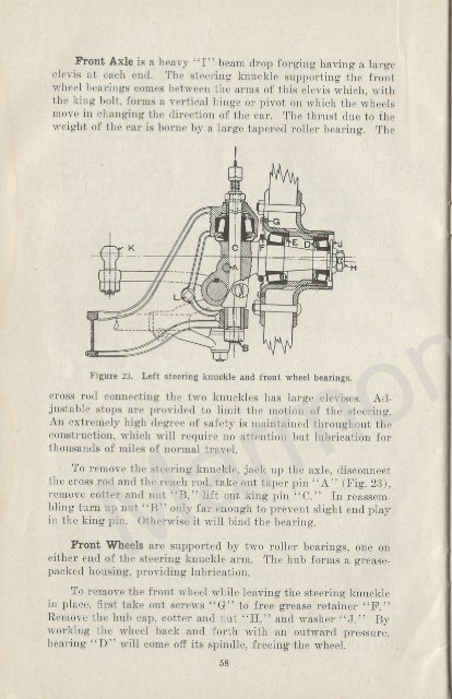
Front Axle is a heavy "I" beam drop forging having a large<br />
clevis at each end. The steering knuckle supporting the front<br />
wheel bearings comes between the arms of this clevis which, with<br />
the king bolt, forms a vertical hinge or pivot on which the wheels<br />
move in changing the direction of the car. The thrust due to the<br />
weight of the car is borne by a large tapered roller bearing. The<br />
Figure 23. Left steering knuckle and front wheel bearings.<br />
cross rod connecting the two knuckles has large devises. Adjustable<br />
stops are provided to limit the motion of the steering.<br />
An extremely high degree of safety is maintained throughout the<br />
construction, which will require no attention but lubrication for<br />
thousands of miles of normal travel.<br />
To remove the steering knuckle, jack up the axle, disconnect<br />
the cross rod and the reach rod, take out taper pin "A" (Fig. 23),<br />
remove cotter and nut "B," lift out king pin "C." In reassembling<br />
turn up nut "B" only far enough to prevent slight end play<br />
in the king pin. Otherwise it will bind the bearing.<br />
Front Wheels are supported by two roller bearings, one on<br />
either end of the steering knuckle arm. The hub forms a greasepacked<br />
housing, providing lubrication.<br />
To remove the front wheel while leaving the steering knuckle<br />
in place, first take out screws "G" to free grease retainer "F."<br />
Remove the hub cap, cotter and nut "H," and washer "J." By<br />
working the wheel back and forth with an outward pressure,<br />
bearing "D" will come off its spindle, freeing-the wheel.<br />
58<br />
Adjusting Wheel Bearings. In replacing, pack with grease<br />
and turn up nut "H" until the wheel binds, revolving the wheel a<br />
few times to take up back lash. Then relieve one-fourth turn to<br />
give 1 he bearings proper clearance. Test by seeing that the wheel<br />
runs free. With the proper adjustment by grasping opposite<br />
spokes in a vertical line and pushing on one and pulling on the<br />
other, play will be barely perceptible. When you have the adjustment<br />
just right lock the nut and replace cap.<br />
Rear System,<br />
The rear axle housing construction<br />
follows the <strong>Marmon</strong><br />
precedent, having two pressed<br />
steel sections welded together.<br />
It performs the important function<br />
of supporting the load on<br />
the rear wheels, carrying the<br />
driving members (bevel gears,<br />
differential and axle shaft) in a<br />
bath of grease, and also carries<br />
the brakes. It is made up as a<br />
complete 'unit with these parts,<br />
and may be removed if desired<br />
by disconnecting the torque bar,<br />
the flange at the rear universal,<br />
brake rods, shock absorbers, rebound<br />
straps and springs. Further<br />
disassembling of driving<br />
units, adjustment of brakes or<br />
wheel bearings may now be done<br />
as directed elsewhere.<br />
, N451""<br />
*pa<br />
Torque Bar,<br />
As power from the motor<br />
tends to make the rear wheels<br />
Figure 24. Vertical section through<br />
revolve, the axle housing naturally<br />
tends to revolve in the<br />
wheel bearings.<br />
rear wheel. Showing brakes and<br />
opposite direction. The long<br />
"torque" arm takes care of this "torque," or tendency to revolve.<br />
It does not take any driving or side sway stress, as these<br />
are efficiently cared for by the springs, as described on page 56.<br />
A long pin or swivel at the rear end joins the torque bar to the<br />
axle housing, rigidly for vertical or rotary motion, but flexible<br />
sidewise. The ball which terminates the forward end of the<br />
torque bar is carried in a vertical tube which contains cups above<br />
and below held against the ball by powerful coil springs. This<br />
<strong>Marmon</strong><strong>41</strong>.com<br />
59