AIR CIRCUIT BREAKERS - Electrical and Electronics Division
AIR CIRCUIT BREAKERS - Electrical and Electronics Division
AIR CIRCUIT BREAKERS - Electrical and Electronics Division

You also want an ePaper? Increase the reach of your titles
YUMPU automatically turns print PDFs into web optimized ePapers that Google loves.
1<br />
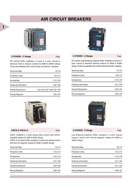
C-POWER : C Range Page<br />
CE marked ACBs, available in 3 pole or 4 pole, manual or<br />
electrical, fixed or drawout versions for 800A to 6300A ratings.<br />
These are available with a wide variety of protection releases.<br />
Technical Data 1/2-1/5<br />
Protection Units 1/6-1/14<br />
Accessories 1/15-1/19<br />
Ordering Information 1/20-1/22<br />
Overall Dimensions 1/24,1/25,1/27-1/29,1/32-1/34<br />
Wiring Diagrams 1/35,1/37<br />
CNCS & CNCS..E Page<br />
CNCS: Available in 3 pole manual fixed version with thermomagnetic<br />
release for 400A & 630A ratings.<br />
CNCS..E: Compact ACBs, available in 3 pole manual fixed version<br />
with thermo-magnetic release for 630A to 2000A ratings.<br />
Technical Data 1/2-1/4<br />
Protection Units 1/13,1/14<br />
Accessories 1/16-1/19<br />
Ordering Information 1/21,1/22<br />
Overall Dimensions 1/23,1/26<br />
Wiring Diagrams 1/36,1/37<br />
<strong>AIR</strong> <strong>CIRCUIT</strong> <strong>BREAKERS</strong><br />
C-POWER : H Range Page<br />
CE marked, High Breaking Capacity ACBs. Available in 3 pole or 4<br />
pole, manual or electrical drawout versions for 800A to 4000A<br />
ratings. These are available with a wide variety of protection releases.<br />
Technical Data 1/2-1/5<br />
Protection Units 1/6-1/14<br />
Accessories 1/15-1/19<br />
Ordering Information 1/21,1/22<br />
Overall Dimensions 1/30-1/34<br />
Wiring Diagrams 1/35,1/37<br />
C-POWER : S Range Page<br />
Low Breaking Capacity ACBs, available in 3 pole manual<br />
drawout version with thermo-magnetic release for 800A to<br />
1600A ratings.<br />
Technical Data 1/2-1/4<br />
Protection Units 1/13,1/14<br />
Accessories 1/15-1/19<br />
Ordering Information 1/21,1/22<br />
Overall Dimensions 1/31-1/34<br />
Wiring Diagrams 1/36,1/37
SALIENT �EATURES<br />
L&T’s Air Circuit Breakers (ACBs), specially designed for extreme tropical conditions, have a proven track record of more than 30 years.<br />
L&T is one amongst the world’s five largest manufacturers of ACBs <strong>and</strong> has supplied over 2,00,000 ACBs for diverse applications in over<br />
40 countries in the world.<br />
These ACBs, which adhere to stringent requirements of protection <strong>and</strong> discrimination in low voltage networks, are type tested at ASTA,<br />
U.K. for compliance to IEC 60947-2 & BSEN 60947-2 st<strong>and</strong>ards & at CPRI, ERDA, India for compliance to IS 13947 - Part 2.<br />
C & H ranges of C-POWER ACBs carry the ‘CE’ mark & meet the requrements of European LV directive for safety & EMC directive.<br />
L&T offers the widest range of ACBs which are available in 3 or 4 pole configuration, fixed or drawout version, auto or manual reset type,<br />
with independent manual or stored energy type manual or electrically operated mechanism. Various terminal orientation options are<br />
available including flat rear type, horizontal rear type, vertical rear type <strong>and</strong> front type.<br />
These ACBs are available with a wide variety of over current protection devices :<br />
✦ Computer compatible & Communication capable release type SR61C.<br />
✦ Microprocessor based Releases type SR21 & SR21E.<br />
✦ Solid State Releases type SR15 & SR15G.<br />
✦ Thermomagnetic Releases type DN1.<br />
There are over 500 options to choose from.<br />
PRODUCT HIGHLIGHTS<br />
✦ Widest range of ACBs : 400A to 6300A.<br />
✦ Elegant design having rugged construction.<br />
✦ I for 1sec = I = I to ensure complete selectivity.<br />
cw cs cu<br />
✦ High mechanical & electrical life.<br />
✦ Unique pole design ensures bounce free contact operation.<br />
✦ All 4-pole ACBs have fully rated neutral pole. Hence the poles<br />
at either extreme can be used as the neutral i.e. in NRYB or<br />
RYBN configuration.<br />
✦ Utilisation category ‘B’ i.e. discrimination possible with all releases.<br />
✦ All ratings can be used for ON/O�� Load Isolation.<br />
✦ Single stroke of h<strong>and</strong>le to close independent manual ACBs.<br />
✦ Unique sliding shutters to prevent unauthorized access to “Trip”<br />
& “Close” Push button.<br />
✦ Auxiliary contacts in drawout ACBs are programmable for service<br />
<strong>and</strong> test position.<br />
✦ Optimally compact ACBs to ensure low temperature rise.<br />
USER �RIENDLINESS<br />
✦ Over current release settings, telescopic racking h<strong>and</strong>le <strong>and</strong><br />
various racking interlocks are accessible from front. This means<br />
that the panel door is not required to be opened for accessing<br />
the above.<br />
✦ Wide choice of terminal orientations (�lat, Horizontal, Vertical<br />
<strong>and</strong> �ront).<br />
✦ Easy racking on telescopic rails.<br />
✦ 4th “Maintenance” position in Drawout type ACBs to facilitate<br />
maintenance.<br />
✦ Multitap CTs for enhancing protection range.<br />
✦ Wide variety of ampemetric <strong>and</strong> voltmetric releases.<br />
SUPERIOR AESTHETICS IN C-POWER ACBs<br />
✦ Aesthetically designed front-facia featuring common panel cutouts<br />
for fixed breakers <strong>and</strong> drawout breakers.<br />
✦ Common height of all ‘H’ Range ACBs.<br />
✦ Left aligned panel appearance.<br />
✦ Left aligned mechanism for effective space utilization of panel.<br />
✦ Unique gasket for IP54 protection.<br />
SA�ETY<br />
✦ ‘CE’ marking on C & H ranges of C-POWER ACBs.<br />
✦ Superior quality of engineering grade plastics used for insulation<br />
purpose. Conform to glow wire test (Ref.: IEC 60695-2-1)<br />
✦ In-built mechanical anti-pumping for electrically operated ACBs.<br />
✦ In-built safety lever in Drawout type ACBs to ensure tripping of<br />
ACB :<br />
• before breaker jaws disengage from cradle terminals while<br />
racking out the ACB from “Service” position.<br />
• before breaker jaws engage with cradle terminals while racking<br />
in the ACB from “Isolated” or “Test” position.<br />
✦ In-built rating error preventor in Drawout ACBs to ensure correct<br />
rating of breaker in corresponding cradle.<br />
✦ In-built safety shutter assembly to prevent accidental contact<br />
with live cradle terminals when breaker is in drawout position.<br />
This is directly operated without linkages <strong>and</strong> transparent flaps<br />
facilitate easy visibility of terminals.<br />
1/1<br />
1
1 Rating (A) 400 630 800<br />
Type Designation CN-CS CN-CS CN-CS..E CN-CS..E S C H<br />
Rated Current (A) 400C In 400 630 630 800 800 800 800<br />
Rated Operational Voltage (V) 50/60Hz Ue* 415 415 415 415 415 415 415<br />
Rated insulation voltage (V), 50/60Hz Ui 690 690 690 690 1000 1000 1000<br />
No. of poles 3 3 3 3 3 3/4 3/4<br />
Rated ultimate short circuit Icu<br />
breaking capacity<br />
50/60Hz (kA rms)<br />
380/415/500V 36.6 36.6 25 36.6 50 50 65<br />
Rated service short circuit Ics<br />
breaking capcity<br />
50/60Hz (kA rms)<br />
380/415/500V 36.6 36.6 25 36.6 38 50 65<br />
Rated short time withst<strong>and</strong> capacity Icw 0.5sec 36.6 36.6 25 36.6 38 50 65<br />
50/60Hz (kA rms) 1sec 25 25 25 25 38 50 65<br />
Rated making capacity Icm<br />
50/60Hz (kA peak) 380/415/500V 77 77 52.5 77 105 105 143<br />
Rated impulse withst<strong>and</strong> voltage of main circuit (kV), Uimp 8 8 8 8 8 8 8<br />
Rated impulse withst<strong>and</strong> voltage of aux. circuit (kV), Uimp 4 4 4 4 4 4 4<br />
Typical opening time msec 4040404040 4040<br />
Typical closing time msec 6060606060 6060<br />
Utilization category B B B B B B B<br />
Suitability for isolation ü ü ü ü ü ü ü<br />
�ixed ü ü ü ü ü▲<br />
Versions<br />
Dimensions(mm)<br />
1/2<br />
TECHNICAL DATA<br />
Drawout ü ü ü<br />
Manual ü ü ü ü ü ü ü<br />
<strong>Electrical</strong> ü ü<br />
CT taps for Thermo-Magnetic (DN1), Solid State (SR15, SR15G) Releases Amps 320,400 400,500,630 400,500,640,800<br />
CT taps for Microprocessor based (SR21, SR21E & SR61C) Releases Amps --- --- --- --- 800<br />
<strong>Electrical</strong> & Mechanical life (Operating Cycles)** 15,000 15,000 15,000 20,000 20,000 20,000<br />
Fixed D<br />
H 385 385 385 385 394<br />
3 pole 331.2 331.2 331.2 331.2<br />
378<br />
H<br />
W<br />
4 pole NA NA NA NA<br />
NA<br />
466<br />
NA<br />
D 447 447 447 447 431<br />
Drawout<br />
D<br />
H 468 468 468<br />
H<br />
W<br />
3pole<br />
4 pole<br />
NA<br />
399<br />
NA<br />
399<br />
487<br />
399<br />
487<br />
D 587 587 587<br />
NA - Not Available<br />
* Please consult us for applications at higher operational voltages upto 1000V <strong>and</strong> dc voltages.<br />
** <strong>Electrical</strong> life = Mechanical life, however arcing contacts need to be replaced depending upon wear.<br />
Arcing contacts are readily available as spares & easily replaceable at site.<br />
▲ Available in CN-CS version also.<br />
Note:1) CN-CS400, CN-CS630, 630E, 800E & 1000E ACB are available only with DN1 release.<br />
2) A Choice of straight horizontal rear, straight vertical rear, flat rear <strong>and</strong> front terminal orientations in all drawout ACBs.<br />
3) Data of Icw rating for 3 sec is available on request.
Versions<br />
Dimensions(mm)<br />
TECHNICAL DATA<br />
Rating (A) 1000 1250<br />
Type Designation CN-CS..E S C H CN-CS..E S C H<br />
Rated Current (A) 400C In 1000 1000 1000 1000 1250 1250 1250 1250<br />
Rated Operational Voltage (V) 50/60Hz Ue* 415 415 415 415 415 415 415 415<br />
Rated insulation voltage (V), 50/60Hz Ui 690 1000 1000 1000 1000 1000 1000 1000<br />
No. of poles 3 3 3/4 3/4 3 3 3/4 3/4<br />
Rated ultimate short circuit Icu<br />
breaking capacity<br />
50/60Hz (kA rms)<br />
380/415/500V 36.6 50 50 65 50 50 50 65<br />
Rated service short circuit Ics<br />
breaking capcity<br />
50/60Hz (kA rms)<br />
380/415/500V 36.6 38 50 65 50 38 50 65<br />
Rated short time withst<strong>and</strong> capacity Icw 0.5sec 36.6 38 50 65 50 38 50 65<br />
50/60Hz (kA rms) 1sec 25 38 50 65 50 38 50 65<br />
Rated making capacity Icm<br />
50/60Hz (kA peak) 380/415/500V 77 105 105 143 105 105 105 143<br />
Rated impulse withst<strong>and</strong> voltage of main circuit (kV), Uimp 8 8 8 8 8 8 8 8<br />
Rated impulse withst<strong>and</strong> voltage of aux. circuit (kV), Uimp 4 4 4 4 4 4 4 4<br />
Typical opening time msec 4040 404040 404040<br />
Typical closing time msec 6060 606060 606060<br />
Utilization category B B B B B B B B<br />
Suitability for isolation ü ü ü ü ü ü ü ü<br />
�ixed ü ü▲ü ü<br />
Drawout ü ü ü ü ü ü<br />
Manual ü ü ü ü ü ü ü ü<br />
<strong>Electrical</strong> ü ü ü ü<br />
CT taps for Thermo-Magnetic (DN1), Solid State (SR15, SR15G) Releases Amps 800, 1000 1000, 1250<br />
CT taps for Microprocessor based (SR21, SR21E & SR61C) Releases Amps --- --- 1000 --- 1250<br />
<strong>Electrical</strong> & Mechanical life (Operating Cycles)** 15,000 20,000 20,000 20,000 20,000 20,000 20,000 20,000<br />
�ixed<br />
D<br />
H 385 394 385 394<br />
3 pole 331.2 378 378 378<br />
W<br />
4 pole NA<br />
NA<br />
466<br />
NA<br />
NA<br />
NA<br />
466<br />
NA<br />
H<br />
D 447 431 447 431<br />
Drawout<br />
D<br />
H 468 468 468 468 468 468<br />
H<br />
W<br />
3pole<br />
4 pole<br />
NA<br />
399<br />
NA<br />
399<br />
487<br />
399<br />
487<br />
NA<br />
399<br />
NA<br />
399<br />
487<br />
399<br />
487<br />
D 587 587 587 587 587 587<br />
1/3<br />
1
1 Rating (A) 1600 2000 2500<br />
Type Designation S C H E C H C H<br />
Rated Current (A) 400C In 1600 1600 1600 2000 2000 2000 2500 2500<br />
Rated Operational Voltage (V) 50/60Hz Ue* 415 415 415 415 415 415 415 415<br />
Rated insulation voltage (V), 50/60Hz Ui 1000 1000 1000 1000 1000 1000 1000 1000<br />
No. of poles 3 3/4 3/4 3 3/4 3/4 3/4 3/4<br />
Rated ultimate short circuit Icu<br />
breaking capacity<br />
50/60Hz (kA rms)<br />
380/415/500V 50 50 65 50 55 75 60 75<br />
Rated service short circuit Ics<br />
breaking capcity<br />
50/60Hz (kA rms)<br />
380/415/500V 38 50 65 50 55 75 60 75<br />
Rated short time withst<strong>and</strong> capacity Icw 0.5sec 38 5065 5055 75 60 75<br />
50/60Hz (kA rms) 1sec 38 50 65 50 55 75 60 75<br />
Rated making capacity Icm<br />
50/60Hz (kA peak) 380/415/500V 105 105 143 105 121 165 132 165<br />
Rated impulse withst<strong>and</strong> voltage of main circuit (kV), Uimp 8 8 8 8 8 8 8 8<br />
Rated impulse withst<strong>and</strong> voltage of aux. circuit (kV), Uimp 4 4 4 4 4 4 4 4<br />
Typical opening time msec 40 4040 40404040 40<br />
Typical closing time msec 60 6060 60606060 60<br />
Utilization category B B B B B B B B<br />
Suitability for isolation ü ü ü ü ü ü ü ü<br />
�ixed ü ü ü ü<br />
Versions<br />
Dimensions(mm)<br />
1/4<br />
TECHNICAL DATA<br />
Drawout ü ü ü ü ü ü ü<br />
Manual ü ü ü ü ü ü ü ü<br />
<strong>Electrical</strong> ü ü ü ü ü ü<br />
CT taps for Thermo-Magnetic (DN1), Solid State (SR15, SR15G) Releases Amps 1250,1600 1000,1250,1600,2000 2000,2500<br />
CT taps for Microprocessor based (SR21, SR21E & SR61C) Releases Amps --- 1600 --- 2000 2500<br />
<strong>Electrical</strong> & Mechanical life (Operating Cycles)** 20,000 20,000 20,000 20,000 20,000 20,000 20,000 20,000<br />
Fixed<br />
D<br />
H 394 385 394 394<br />
3 pole 378 378 534 534<br />
W<br />
4 pole<br />
NA<br />
466<br />
NA<br />
NA 680<br />
NA<br />
680<br />
NA<br />
H<br />
D 431 447 431 431<br />
Drawout<br />
D<br />
H 468 468 468 468 468 468 468<br />
H<br />
W<br />
3pole<br />
4 pole<br />
399<br />
NA<br />
399<br />
487<br />
399<br />
487<br />
NA<br />
555<br />
701<br />
555<br />
701<br />
555<br />
701<br />
555<br />
701<br />
D 587 587 587 587 587 587 587<br />
NA - Not Available<br />
* Please consult us for applications at higher operational voltages upto 1000V <strong>and</strong> dc voltages.<br />
** <strong>Electrical</strong> life = Mechanical life, however arcing contacts need to be replaced depending upon wear.<br />
Arcing contacts are readily available as spares & easily replaceable at site.<br />
▲ Available in CN-CS version also.<br />
Note:1) A Choice of straight horizontal rear, straight vertical rear, flat rear <strong>and</strong> front terminal orientations in all drawout ACBs.<br />
2) Data of Icw rating for 3 sec is available on request.
Versions<br />
Dimensions(mm)<br />
TECHNICAL DATA<br />
Rating (A) 3200 4000 5000 6300<br />
Type Designation D H1 C H C C<br />
Rated Current (A) 400C In 3200 3200 4000 4000 5000 6300<br />
Rated Operational Voltage (V) 50/60Hz Ue* 415 415 415 415 415 415<br />
Rated insulation voltage (V), 50/60Hz Ui 1000 1000 1000 1000 1000 1000<br />
No. of poles 3/4 3 3/4 3 3 3<br />
Rated ultimate short circuit Icu<br />
breaking capacity<br />
50/60Hz (kA rms)<br />
380/415/500V 70 100 70 100 85 85<br />
Rated service short circuit Ics<br />
breaking capcity<br />
50/60Hz (kA rms)<br />
380/415/500V 70 100 70 100 85 85<br />
Rated short time withst<strong>and</strong> capacity Icw 0.5sec 701 0 701 0 –– ––<br />
50/60Hz (kA rms) 1sec 70 100 70 100 85 85<br />
Rated making capacity Icm<br />
50/60Hz (kA peak) 380/415/500V 154 220 154 220 187 187<br />
Rated impulse withst<strong>and</strong> voltage of main circuit (kV), Uimp 8 8 8 8 8 8<br />
Rated impulse withst<strong>and</strong> voltage of aux. circuit (kV), Uimp 4 4 4 4 4 4<br />
Typical opening time msec 4040 40404040<br />
Typical closing time msec 6060 60606060<br />
Utilization category B B B B B B<br />
Suitability for isolation ü ü ü ü ü ü<br />
�ixed ü ü<br />
Drawout ü ü ü ü ü ü<br />
Manual ü ü ü ü ü ü<br />
<strong>Electrical</strong> ü ü ü ü ü ü<br />
CT taps for Thermo-Magnetic (DN1), Solid State (SR15, SR15G) Releases Amps 1600,2000,2500,3200 2000,2500,3200,4000 –– ––<br />
CT taps for Microprocessor based (SR21, SR21E & SR61C) Releases Amps 3200 4000 5000 6300<br />
<strong>Electrical</strong> & Mechanical life (Operating Cycles)** 10,000 10,000 5,000 5,000 5,000 5,000<br />
Fixed<br />
D<br />
H 509 509<br />
3 pole 688 688<br />
W<br />
4 pole 890<br />
NA<br />
890<br />
NA NA NA<br />
H<br />
D 518 518<br />
Drawout<br />
D<br />
H 583 468 583 468 583 583<br />
H<br />
W<br />
3pole 711 701 711 701 913 913<br />
4 pole 913 NA 913 NA NA NA<br />
D 652 607 678 607 691 691<br />
1/5<br />
1
1<br />
1/6<br />
SR21 SR21E<br />
Note : 3 phase, 4 wire system, Neutral CT for earthfault is required.<br />
Type of<br />
Protection<br />
PROTECTION<br />
MICROPROCESSOR BASED<br />
SALIENT �EATURES O� RELEASES TYPE SR21 & SR21E<br />
✦ Incorporate 8-bit microprocessor.<br />
✦ True RMS measurement.<br />
✦ True hot <strong>and</strong> cold characteristics.<br />
✦ Thermal memory takes care of residual heat in case of repeat<br />
overloads. Thermal memory can be bypassed, if required.<br />
✦ Comprehensive protection functions : long time, short time,<br />
instantaneous <strong>and</strong> ground fault.<br />
✦ Reliable tripping by direct operation on trip mechanism of the<br />
breaker.<br />
✦ No external power supply.<br />
✦ Built-in electromechanical fault status indicators in SR21 release.<br />
✦ Zone selective interlocking on short circuit <strong>and</strong> ground fault.<br />
✦ Self-diagnostic <strong>and</strong> self-correcting watchdog provision.<br />
✦ SRT-2 Test kit available for verifying the release operation.<br />
✦ Suitable for 50/60 Hz systems.<br />
✦ Annunciation module available for remote indication of each type<br />
of fault.<br />
Setting Ranges<br />
Pick-up current Time Delay<br />
Ir-0.5 to 1.0 times In 0.2 to 30 sec. at 6 Ir<br />
Long Time Steps : 0.50, 0.60, 0.65, 0.70, 0.75,<br />
0.80, 0.85, 0.9, 0.95, 1.00<br />
Steps : 0.2, 0.5, 1, 1.5, 2, 3, 5, 6, 12, 17, 30s<br />
2 to 10 times Ir 20ms to 600 ms<br />
Short Time Steps : 2, 3, 4, 5, 6, 7, 8, 9, 10 Steps : 20, 60, 100, 160, 200, 260, 300<br />
400, 500, 600 ms<br />
2 to 16 times In<br />
Instantaneous Steps : 2, 3, 4, 6, 8, 10, 12, 14, 16<br />
One position as infinity<br />
0.2 to 0.6 times In 100 to 400 ms<br />
Ground �ault Steps : 0.2, 0.3, 0.4, 0.5, 0.6 Steps : 100, 200, 300, 400 ms & infinity<br />
Note: Positioning the knob to infinity position will suppress the corresponding protection.<br />
In is the nominal current which is the CT tap value.<br />
Ir is the rated current which is the setting of pick-up current for long time in the release.<br />
E.g. 1000A CT has taps of 800A & 1000A <strong>and</strong> if 800A tap is selected, then the nominal current (In) is 800A.<br />
If the long time pick-up knob is at 0.5, then the rated current (Ir) is 0.5 x 800A = 400A.
PROTECTION<br />
MICROPROCESSOR BASED<br />
CHARACTERISTIC CURVE<br />
Long Time & Short time<br />
SR21/ 21E<br />
Instantaneous<br />
SR21/ 21E<br />
Ir<br />
1/7<br />
1
1<br />
1/8<br />
Type of<br />
Protection<br />
PROTECTION<br />
COMPUTER COMPATIBLE & COMMUNICATION CAPABLE<br />
SALIENT �EATURES O� RELEASE TYPE SR61C<br />
✦ Display of rms currents (Phase, Highest among phases) <strong>and</strong> Trip data by 4-seven<br />
segment LEDs.<br />
✦ Non-volatile memory for Storage <strong>and</strong> display of trip history for last 5 tripping<br />
operations.<br />
✦ Communication with PC <strong>and</strong> breaker control through RS485 port.<br />
✦ Serial communication by MODBUS-RTU protocol.<br />
✦ Separate indication for Power-ON <strong>and</strong> Programming mode or fault.<br />
✦ Individual fault indication by LEDs. LED indication can be reset by the Reset button<br />
on the release. However, resetting is not possible when fault is present.<br />
✦ Direct tripping of breaker - Reliable <strong>and</strong> Minimum tripping time.<br />
✦ Blocking function to inhibit any of the trip functions to achieve intelligent<br />
discrimination.<br />
✦ Protection against failure of breaker to trip within set time delay (Range : 0.05 s to<br />
0.25 s in steps of 0.01 s)<br />
✦ Automatic doubling feature to prevent nuisance tripping during motor starting. Can<br />
be Enabled or Disabled.<br />
✦ Protection settings can be changed through computer while breaker is carrying<br />
current.<br />
✦ 5 Output relays<br />
R1 Used for trip output (Can be programmed in manual or auto reset mode)<br />
R2 �or Instantaneous output<br />
R3 �or opening the breaker<br />
R4 �or closing the breaker<br />
R5 �or indication of internal error / program error / auxiliary supply failure<br />
✦ Auxiliary power supply required : 110V to 240V ac/dc +10%<br />
Auxiliary power supply burden < 10 VA<br />
Setting Ranges<br />
Pick-up current Time Delay<br />
Ir-0.5 to 1.0 times In 2 to 30 sec. at 6 times Ir<br />
Long Time Steps : 0.50, 0.55, 0.60, 0.65, 0.70, 0.75,<br />
0.80, 0.85, 0.9, 0.95, 1.00<br />
Steps : 2, 10, 20, 30 sec<br />
2 to 16 times In Inst. to 400 ms<br />
Short Time Steps : 2, 3, 4, 6, 8, 10, 12, 14, 16 Steps : Inst., 100, 200, 300, 400 ms<br />
0.2 to 0.6 times In 100 to 400 ms<br />
Ground �ault Steps : 0.2, 0.3, 0.4, 0.5, 0.6 Steps : 100, 200, 300, 400 ms & Disable
PROTECTION<br />
COMPUTER COMPATIBLE & COMMUNICATION CAPABLE<br />
CHARACTERISTIC CURVE<br />
Long Time<br />
SR61C<br />
1/9<br />
1
1<br />
1/10<br />
ZONE SELECTIVE INTERLOCKING<br />
Zone Selectivity, applicable to short circuit protection function allows one to obtain shorter trip times for the circuit breaker closest to the<br />
fault than in the case of time based selectivity. The word zone is used to refer to the part of an installation between two circuit breakers<br />
in series. Every circuit breaker which detects a fault, communicates this to the circuit breaker upstream using a simple connection wire.<br />
The fault zone is the zone immediately downstream of the circuit breaker which detects the fault but does not receive any communication<br />
from those downstream. This circuit breaker opens without waiting for the time delay set. All ratings of C-POWER ACBs with SR21/<br />
SR21E/SR61C releases allow one to obtain zone selectivity as explained below.<br />
A, B, C, D, <strong>and</strong> E are breakers with SR21 / SR21E release <strong>and</strong> are interconnected in cascade as shown. Short time delays are as<br />
indicated to achieve discrimination between upstream <strong>and</strong> downstream breakers. When a fault occurs in zone ‘Z’, breaker ‘E’ trips after<br />
a delay of 100 ms*, <strong>and</strong> breakers ‘C’ <strong>and</strong> ‘A’ follow delays of 200 ms* <strong>and</strong> 300 ms*, respectively, if required. But in case of a fault at ‘Y’<br />
breaker ‘C’ trips after a delay of 60 ms*, a default value, instead of 200 ms*. This is because of the communication between releases in<br />
circuit breakers ‘C’ <strong>and</strong> ‘E’. Similarly, a fault in zone ‘X’ results in breaker ‘A’ tripping after delay of 60 ms* instead of 300 ms*, thus<br />
achieving intelligent discrimination.<br />
This intelligent discrimination is achieved in communication capable release type SR61C by programming its blocking function.<br />
* Breaker opening time additional.
Type of<br />
Protection<br />
* Available in SR 15G release only.<br />
PROTECTION<br />
SOLID STATE<br />
Setting Ranges of SR15 & SR15G<br />
SALIENT �EATURES O� RELEASES TYPE SR15 & SR15G<br />
✦ Comprehensive protection<br />
SR15 - Long Time <strong>and</strong> Short Time<br />
SR15G - Long Time, Short Time <strong>and</strong> Ground �ault.<br />
✦ Wide range of current adjustments possible<br />
✦ Choice of three I-t characteristics in long time zone.<br />
✦ Hot <strong>and</strong> cold characteristics.<br />
✦ Thermal memory takes care of residual heat in case of repetitive<br />
overloads.<br />
✦ Reliable tripping by direct operation on the breaker trip shaft.<br />
✦ No external power supply required.<br />
✦ Power On LED.<br />
✦ SRT-1 Test kit is available for verifying the release operation.<br />
✦ Suitable for 50/60 Hz systems.<br />
✦ Annunciator module available for remote indication of each type<br />
of fault.<br />
Setting Ranges<br />
Pick-up current Time Delay<br />
Long Time Ir - 0.5 to 1.0 times In 2.5 sec, 13 sec, 25 sec at 6 Ir<br />
Short Time 2 to 10 times In Inst. to 400 ms.<br />
Ground �ault* 0.2 to 0.5 times In 100 to 400 ms.<br />
1/11<br />
1
1<br />
1/12<br />
PROTECTION<br />
SOLID STATE<br />
CHARACTERISTIC CURVE<br />
Long Time (delay 25 sec.) <strong>and</strong> Short time<br />
SR15/15G<br />
Long Time (delay 2.5 sec. <strong>and</strong> 13 sec.)<br />
SR15/15G
PROTECTION<br />
THERMO-MAGNETIC<br />
CHARACTERISTICS<br />
I-t Characteristics for DN1 Release<br />
Note :<br />
�or exact values of magnetic thershold refer overcurrent release table.<br />
Thermal Characteristics shown above are for dial setting of 1.0 in DN1 overcurrent release.<br />
SALIENT �EATURES O� THERMO MAGNETIC OVERCURRENT<br />
RELEASE TYPE DN1<br />
• Comprehensive protection - Long Time & Short Time.<br />
• Sensing through Current transformers.<br />
• Wide range of overload <strong>and</strong> short circuit setting possible with<br />
multi-tap CTs.<br />
• True RMS sensing.<br />
• Each phase can be individually adjusted for overload <strong>and</strong> short<br />
circuit settings.<br />
• Ambient temperature compensated from -50C to + 500C. • Suitable for 50/60Hz systems.<br />
• Mechanical trip test facility available.<br />
Overload Protection<br />
• Provided by bi-metals.<br />
• Continuously adjustable dial settings from 75% to 100% of CT<br />
tap.<br />
• Inverse time characteristics on overload.<br />
Short Circuit Protection<br />
• Provided by electromagnets.<br />
• Multiple settings available.<br />
• �ixed minimum impulsion time of 25 ms on short circuit by means<br />
of a flywheel to prevent tripping due to transients.<br />
1/13<br />
1
1<br />
* Not recommended<br />
1/14<br />
PROTECTION<br />
OVERCURRENT SETTINGS �OR RELEASE TYPE DN1<br />
Type Designation CT CT Tap Setting of Magnetic Release Thermal Current Setting<br />
(Amp.) (Amps.) (Amps.)<br />
DN1 taps<br />
M1 M2<br />
CN-CS 400 400 320 1800 * 240 to 320<br />
400 2300 * 300 to 400<br />
CN-CS 630 / 630 E 630 400 2500 * 300 to 400<br />
500 3000 3700 375 to 500<br />
630 3600 4500 472 to 630<br />
CN-CS 800 E/S/C/H 500 400 2700 * 300 to 400<br />
500 3200 3900 375 to 500<br />
800 640 3900 4900 480 to 640<br />
800 4700 6000 600 to 800<br />
CN-CS 1000 E/S/C/H 1000 800 4700 6000 600 to 800<br />
1000 5700 7200 750 to 1000<br />
CN-CS 1250 E/S/C/H 1250 1000 5700 7200 750 to 1000<br />
1250 7000 8900 940 to 1250<br />
CN-CS 1600 S/C/H 1600 1250 7000 8900 940 to 1250<br />
1600 8800 11500 1200 to 1600<br />
CN-CS 2000 E/C/H 1250 1000 5700 7200 750 to 1000<br />
1250 7000 8900 940 to 1250<br />
2000 1600 8800 11500 1200 to 1600<br />
2000 11000 14000 1500 to 2000<br />
CN-CS 2500 C/H 2500 2000 11000 14000 1500 to 2000<br />
2500 13500 17000 1875 to 2500<br />
CN-CS 3200 D 2000 1600 8500 11500 1200 to 1600<br />
2000 11500 16000 1500 to 2000<br />
3200 2000 12500 16500 1500 to 2000<br />
2500 14000 18000 1875 to 2500<br />
3200 17000 23000 2400 to 3200<br />
CN-CS 3200 H1 3200 2500 14000 17500 1875 to 2500<br />
3200 17500 22000 2400 to 3200<br />
CN-CS 4000 C/H 4000 2000 12500 16500 1500 to 2000<br />
2500 14000 18000 1875 to 2000<br />
3200 17000 23000 2400 to 3200<br />
4000 22000 29000 3000 to 4000<br />
Operating Limits 0.8 - 1.2 of setting 1.05 - 1.2 of setting
ACCESSORIES<br />
LOCKS/INTERLOCKS<br />
Type Data Type Catalogue No.<br />
LOCKABLE TRIP PUSH BUTTON (LTPB) LTPB is suitable for fixed as well as draw-out manual or electrical ACBs.<br />
�or interlocking, LTPBs are offered in following combinations :<br />
• 4 different types of keys i.e. AA, BB, CC <strong>and</strong> DD suitable for 2 incomers<br />
<strong>and</strong> 1 bus coupler schemes.<br />
• Combination of L, M, N, LM <strong>and</strong> MN locks, which are suitable for<br />
three incomer <strong>and</strong> two bus coupler schemes.<br />
• Combination of K, L, M, N, KL, LM, <strong>and</strong> MN locks, which are suitable<br />
for four incomer <strong>and</strong> three bus coupler schemes.<br />
• Combination of J, K, L, M, N, JK, KL, LM <strong>and</strong> MN locks, which are<br />
suitable for five incomer <strong>and</strong> four bus coupler schemes<br />
View of the cradle<br />
Door<br />
Interlock<br />
Racking<br />
Interlock<br />
Locking in<br />
‘Isolated’<br />
Position<br />
* Available on request as special ACBs<br />
A) Locking in Isolated Position (LIP)<br />
The facility of locking in Isolated position is available in D/O ACBs,<br />
both Manual <strong>and</strong> <strong>Electrical</strong> Versions.<br />
This feature is useful in achieving interlocking between Mains &<br />
St<strong>and</strong>by source. (Normally 2 incomer <strong>and</strong> one bus coupler)<br />
• The key is inserted in breaker <strong>and</strong> unlocked. This ACB can then be<br />
racked in to Service position <strong>and</strong> closed.<br />
B) Door Interlock<br />
The functioning of door interlock can be explained with reference to<br />
two positions<br />
1) Door is open <strong>and</strong> breaker in isolated Position.<br />
Door Interlock ensures that unless the door is closed, breaker<br />
cannot be racked into test & service position.<br />
2) Door is closed <strong>and</strong> breaker in service/test position.<br />
When the breaker is in service or test position, it is not possible to<br />
open the door.<br />
C) Racking Interlock<br />
This ensures that breaker cannot be racked in/out unless it is in<br />
tripped/open condition.<br />
Mechanical Interlock<br />
It is possible to provide “Mechanical Interlock” between two breakers of<br />
the same or different ratings in vertical or horizontal configurations.<br />
Mechanical Interlock is available for ACBs upto 4000A.<br />
Mechanical Interlocking for ACBs in vertical configuration can be provided<br />
by links or by flexible cables. Same for horizontal configuration can be<br />
provided by flexible cables.<br />
Castell-lock<br />
Numbered Castell-lock can also be mounted on C-Power ACBs. This<br />
can be used to Inter-lock with other products such as S-D-� units, MCCBs<br />
etc. Castell-lock is available only for manual ACBs.<br />
AA SL93148OOOA<br />
BB SL93148OOOB<br />
CC SL93148OOOC<br />
DD SL93148OOOD<br />
LIP<br />
A SL93A46OOOA<br />
B SL93A46OOOB<br />
C SL93A46OOOC<br />
D SL93A46OOOD<br />
DOOR I/L<br />
SL93150OOOO<br />
RACKING I/L<br />
A SL93149OOOA<br />
B SL93149OOOB<br />
C SL93149OOOC<br />
D SL93149OOOD<br />
*<br />
*<br />
1/15<br />
1
1<br />
1/16<br />
ACCESSORIES<br />
ACB tripping indication available for the following:<br />
Type Data Catalogue No.<br />
AN1 - ANNUNCIATOR MODULE Remote indication for overload <strong>and</strong> short circuit.<br />
E� 98114OOOO<br />
• Individual fault indication provided by three separate LEDs for<br />
- Long time fault<br />
- Short time/Instantaneous fault<br />
- Ground fault<br />
• Can be used with releases type SR15G/SR21/SR21E<br />
• One potential free contact rated 5A at 230Vac available for each<br />
type of fault<br />
• �lush mounting on panel<br />
• Requires operating voltage : 240V ac/110V dc/220 Vdc. Other<br />
voltages available on request<br />
C5<br />
C1<br />
C2<br />
Common indication for overload <strong>and</strong> short circuit.<br />
• Available for release type DN1 as an option <strong>and</strong> for releases type<br />
SR15/SR15G/ SR21/SR21E/SR61C as st<strong>and</strong>ard.<br />
• Provided by microswitch C1 fitted inside the ACB.<br />
Separate indication for overload <strong>and</strong> short circuit.<br />
• �or release type DN1, this is provided by microswitches C1 & C2<br />
(C2 fitted inside release.)<br />
• Available through fault indicators in SR21 <strong>and</strong> SR61C releases as<br />
st<strong>and</strong>ard feature.<br />
Indication for shunt release operation<br />
• Provided by microswitch C5 fitted on the shunt release.<br />
SL92704OOOO<br />
SL92705OOOO<br />
SL92703OOOO
ACCESSORIES<br />
Type Data Catalogue No.<br />
C3<br />
C8 C6 C7 C9<br />
Microswitch Rating<br />
Indication for under voltage release operation<br />
• Porvided by microswitch C3 fitted on the undervoltage release.<br />
Microswitches for position Indication<br />
• <strong>Electrical</strong> indication available through microswitches.<br />
• Two microswitches with one changeover contact for<br />
i) Service (C6 & C7)<br />
ii) Test or Isolated position (C8 & C9)<br />
• In case of electrical ACB, a service position microswitch is<br />
always fitted on the left side. This prevents remote closing of<br />
ACB in ‘Test’ Position.<br />
Type Rated voltage Rated current<br />
(V) (A)<br />
C2 125 ac 0.5<br />
250 ac 2<br />
30 dc 2<br />
125-250 ac 10<br />
C1,C3 415 ac 5<br />
C5,C6 30 dc 8<br />
C7, C8, 110 dc 0.5<br />
C12 220 dc 0.2<br />
Secondary Isolating Contacts (SIC)<br />
• Self aligned, spring loaded, fully drawout type.<br />
• Required for control circuit connections.<br />
• Maximum four blocks, each of six contacts.<br />
• The contacts are rated at 16A, 500V AC.<br />
• Programmable for service or Test Positions of ACB<br />
SL92703OOOO<br />
SERVICE<br />
(R) SL93142OOOO<br />
(L) SL93143OOOO<br />
TEST/ISOLATED<br />
(R) SL93144OOOO<br />
(L) SL93145OOOO<br />
MOVING-SIC<br />
SL92701OOOO<br />
�IX-SIC<br />
SL93866OOOO<br />
1/17<br />
1
1<br />
OPERATION COUNTER<br />
SRT - 2 for SR21/SR21E releases<br />
SRT - 1 for SR15/SR15G releases<br />
1/18<br />
ACCESSORIES<br />
Type Data Catalogue No.<br />
• Operates mechanically.<br />
• Displays total number of breaker operations cycles.<br />
Test kits for checking functions of releases<br />
• Test kits require control supply for their operation<br />
• Releases should never be tested when breaker is carrying current<br />
XM 81063OOOO<br />
SRT1<br />
ST24045OOOO<br />
SRT2<br />
ST23130OOOO
SHUNT RELEASE<br />
UNDER VOLTAGE RELEASE<br />
AUXILIARY CONTACTS<br />
ACCESSORIES<br />
Type Data Technical Data Catalogue No.<br />
• �or remote tripping of<br />
the breaker.<br />
• Shunt release coil is<br />
short time rated <strong>and</strong><br />
is disconnected from<br />
the circuit by an auxiliary<br />
contact when<br />
the ACB trips (Refer<br />
the wiring diagram),<br />
Two types available:<br />
• EA for dc application<br />
• EA1 for ac application<br />
Two types available :<br />
• Type MV<br />
with no intentional<br />
time delay.<br />
• Type MVR<br />
With fixed time delay<br />
of 3+1.5 sec. to prevent<br />
nuisance tripping<br />
against momentary<br />
voltage dips.<br />
Note : When<br />
undervoltage release is<br />
provided, the ACB can<br />
be closed only when<br />
supply is available to the<br />
undervoltage release.<br />
• Two combinations<br />
available.<br />
2 NO + 2 NC<br />
6 NO + 6 NC<br />
Type Nominal Power Operating<br />
of Voltage Consumption Limits<br />
Release Uc(V) at pick up<br />
50Hz<br />
240 ac 800 VA 10-130%<br />
EA1 415 ac 800 VA Uc<br />
EA 24V dc 32 W<br />
48V dc 125 W 65-130%<br />
110 dc 45 W Uc<br />
220 dc 30 W<br />
Note : Other voltages available on request<br />
Nominal 240V & 415V : 50Hz<br />
voltage (Uc) 220V & 415V : 60Hz<br />
Pick up (V) 80% Uc<br />
Drop off (V) 35-65% Uc<br />
VA Consumption Pick up - 23 VA<br />
Hold on - 10 VA<br />
Watt loss 6 W<br />
<strong>Electrical</strong> Voltage Rated<br />
Circuit (V) current<br />
(A)<br />
Resistive 24 to 415 ac 16<br />
250 V dc 1.2<br />
Non-resistive 24 to 415 ac 16<br />
250 V dc 1.0#<br />
# L/R = 15ms with two contacts in series<br />
110Vdc -SL92718O1OO<br />
220Vdc -SL92718O2OO<br />
24/48Vdc-SL92718O4OO<br />
240Vac -SL92718OBOO<br />
415Vac -SL92718ODOO<br />
MV<br />
240Vac-SL92720BOOO<br />
415Vac-SL92720DOOO<br />
MVR<br />
240Vac-SL92719BOOO<br />
415Vac-SL92719DOOO<br />
�OR RATINGS<br />
�ROM 800A<br />
TO 2500A<br />
2NO+2NC:<br />
SL92765OOOO<br />
6NO+6NC:<br />
SL92767OOOO<br />
�OR RATINGS<br />
�ROM 3200A<br />
TO 6300A<br />
2NO+2NC:<br />
SL92766OOOO<br />
6NO+6NC:<br />
SL92768OOOO<br />
1/19<br />
1
1<br />
All Air Circuit Breakers conform to IS 13947-2 <strong>and</strong> IEC 60947-2. The items listed under column III are st<strong>and</strong>ard ACBs with thermo-magnetic release DN1, CTs &<br />
auto reset. The st<strong>and</strong>ard manually operated fixed breakers come equipped with 6NO + 6NC auxiliary contacts (except for 400 & 630A Manually Operated �ixed<br />
Breakers). The st<strong>and</strong>ard Manual Drawout breakers come equipped with 6NO + 6NC auxiliary contacts & 18 way secondary isolating contacts. The st<strong>and</strong>ard<br />
<strong>Electrical</strong> Drawout breakers come equipped with 6NO + 6NC auxillary contacts, 240V ac or 220 dc shunt release, service position microswitch, 240V ac or 220V<br />
dc motor & 24 way secondary isolating contacts. ACBs are suitable for operational voltage of 415V ac.<br />
The items listed under column IV are ACBs as in column III but without protection release.<br />
The items listed under column V are ACBs as in column III but with solid state analog release SR15G in place of DN1. Column VI indicate 4 pole ACBs with DN1<br />
release.<br />
I II III IV V VI<br />
DESCRIPTION With Thermo-Magnetic Without Protection With Solid State With Thermo-Magnetic<br />
Release (3 Pole) Release (3 Pole) Release (3 Pole) Release (4 Pole)<br />
Catalogue No. Catalogue No. Catalogue No. Catalogue No.<br />
400 A M� SL 92988OOOO<br />
630 A M� SL 92880OOOO<br />
800 A M� SL 92678OOOO * * *<br />
* Available on request as special ACBs<br />
1/20<br />
ORDERING IN�ORMATION �OR STANDARD ACBs<br />
E� SL 93021OOOO * * *<br />
MDO SL 93061OOOO SL93561OOOO SL 93581OOOO ST 25031OOOO<br />
EDO (AC) SL 93081OOOO SL93861OOOO SL 93681OOOO ST 25041OOOO<br />
EDO(DC) SL 93101OOOO * * *<br />
1000 A M� SL 92679OOOO * * *<br />
E� SL 93022OOOO * * *<br />
MDO SL 93062OOOO SL93562OOOO SL 93582OOOO ST 25032OOOO<br />
EDO (AC) SL 93082OOOO SL93862OOOO SL 93682OOOO ST 25042OOOO<br />
EDO(DC) SL 93102OOOO * * *<br />
1250 A M� SL 93003OOOO * * *<br />
E� SL 93023OOOO * * *<br />
MDO SL 93063OOOO SL93563OOOO SL 93583OOOO ST 25033OOOO<br />
EDO (AC) SL 93083OOOO SL93863OOOO SL 93683OOOO ST 25043OOOO<br />
EDO(DC) SL 93103OOOO * * *<br />
1600 A M� SL 93004OOOO * * *<br />
E� SL 93024OOOO * * *<br />
MDO SL 30414OOOO SL93564OOOO SL 93584OOOO ST 25034OOOO<br />
EDO (AC) SL 30415OOOO SL93864OOOO SL 93684OOOO ST 25044OOOO<br />
EDO(DC) SL 93104OOOO * * *<br />
2000 A M� SL 93005OOOO * * *<br />
E� SL 93025OOOO * * *<br />
MDO SL 93065OOOO SL93565OOOO SL 93585OOOO ST 25035OOOO<br />
EDO (AC) SL 93085OOOO SL93865OOOO SL 93685OOOO ST 25045OOOO<br />
EDO(DC) SL 93105OOOO * * *<br />
2500 A M� SL 93006OOOO * * *<br />
E� SL 93026OOOO * * *<br />
MDO SL 93066OOOO SL93566OOOO SL 93586OOOO ST 25036OOOO<br />
EDO (AC) SL 93086OOOO SL93866OOOO SL 93686OOOO ST 25046OOOO<br />
EDO(DC) SL 93106OOOO * * *<br />
3200 A M� * * * *<br />
E� * * * *<br />
MDO SL 93070OOOO SL93570OOOO SL 93590OOOO SL 91289OOOO<br />
EDO (AC) SL 93090OOOO SL93870OOOO SL 93690OOOO SL 91290OOOO<br />
EDO(DC) SL 93110OOOO * * SL 91291OOOO<br />
4000 A M� * * * *<br />
E� * * * *<br />
MDO SL 93068OOOO SL93568OOOO SL 93588OOOO SL 93983OOOO<br />
EDO (AC) SL 93088OOOO SL93868OOOO SL 93688OOOO SL 93981OOOO<br />
EDO(DC) SL 93108OOOO * * SL 93982OOOO
ORDERING IN�ORMATION �OR SPECIAL ACBs<br />
Rating 400 630 800 1000 1250 1600<br />
* Refer Range <strong>and</strong> Product Data for details.<br />
2000 2500 3200 4000 5000 6300<br />
Rated Operational Voltage 415Vac 660Vac Other voltages, please specify<br />
Type* E C D H H1<br />
(Note: D & H1 type of ACBs are available only for 3200A ACB)<br />
No. of Poles 3 4<br />
Versions �ixed Drawout<br />
Type of Closing Independent Stored energy type Stored energy type<br />
Manual Manual (Motor operated)<br />
Wiring Scheme 3 phase, 3 wire 3 phase, 4 wire<br />
Type of Protection SR 61C<br />
SR 21 SR 21E<br />
SR 15G<br />
DN1<br />
SR 15<br />
Type of Reset Manual Auto<br />
Auxillary Contacts 2 NO + NC<br />
6 NO + 6 NC<br />
Voltmetric Release<br />
Shunt Release EA 24/48V dc<br />
EA 110V dc<br />
EA 220V dc<br />
EA1 240V ac<br />
EA1 415V ac<br />
Motor Voltage<br />
110V AC 50/60 Hz<br />
240V AC 50/60 Hz<br />
110V dc<br />
220V dc<br />
Closing Electromagnet<br />
110V 50 Hz<br />
240V 50 Hz<br />
110V dc<br />
220V dc<br />
Other Voltages, Please specify<br />
Under Voltage Release MV 240V ac<br />
MV 415V ac<br />
MVR 240V ac<br />
MVR 415V ac<br />
(Note: MV release is meant for instantaneous tripping of ACB <strong>and</strong> MVR release is for tripping the ACB with<br />
intentional time delay)<br />
1/21<br />
1
1<br />
Terminal Orientation* Straight Horizontal<br />
1/22<br />
Straight Vertical<br />
�ront<br />
* St<strong>and</strong>ard ACBs mentioned on page 1/20 have flat rear terminals for ratings upto 3200A <strong>and</strong><br />
straight horizontal for ratings above 3200A<br />
Signalling Microswitches Shunt release operation<br />
Under voltage release operation<br />
<strong>Electrical</strong> Indication of spring charging<br />
Position Microswitches<br />
-Service Position Left Right<br />
-Test/Isolated Position Left Right<br />
Accessories<br />
-Lockable Trip Push Button<br />
Type AA BB CC DD<br />
OR<br />
Suitable for 3 Incomer + 2 Bus Coupler scheme<br />
4 Incomer + 3 Bus coupler scheme<br />
5 Incomer + 4 Bus coupler scheme<br />
-Mechanical Interlock Through cables for horizontal or vertical configuration of ACBs<br />
Through links for vertical configuration of ACBs<br />
-Castell lock A B C D<br />
-Operation Counter<br />
-ANI Annuciator Module<br />
Accessories for Drawout ACBs<br />
-Door Interlock<br />
ORDERING IN�ORMATION �OR SPECIAL ACBs<br />
-Locking in Any position<br />
-Racking Interlock<br />
Isolated position<br />
Type A B C D<br />
Type A B C D
�or 400 A/630 A 3P<br />
A = 10<br />
OVERALL DIMENSIONS - TYPE CN-CS<br />
A = 5<br />
�or 800 A/1000 A 3P<br />
Note : All Dimensions are in mm.<br />
�ixed ACBs<br />
TERMINAL CONNECTIONS<br />
TERMINAL CONNECTIONS<br />
1/23<br />
1
1<br />
�or 800 A to 2500 A 3P/4P<br />
1/24<br />
Ratings<br />
800/1000A C 3P<br />
1250/1600A C 3P<br />
800/1000A C 4P<br />
1250/1600A C 4P<br />
OVERALL DIMENSIONS - TYPE C<br />
�ixed ACBs<br />
Dimensions (mm)<br />
A D E �<br />
326 57 102 -<br />
414 56 98 98<br />
2000/2500A C 3P 482 83 154 -<br />
2000/2500A C 4P 628 82 150 156<br />
Note : All Dimensions are in mm.<br />
Terminal for 800/1000 C Terminal for 1250/1600/2000/2500 C<br />
TERMINAL CONNECTIONS<br />
800/1000/1250/1600 C<br />
2000/2500 C
�or 3200 D/4000 C 3P/4P<br />
Ratings<br />
OVERALL DIMENSIONS - TYPE C<br />
A B D E �<br />
3200D/4000 C 3P 628 636 112 202 -<br />
3200D/4000 C 4P 830 838 112 202 202<br />
Note : All Dimensions are in mm.<br />
Dimensions (mm)<br />
�ixed ACBs<br />
Terminal for 3200 D/4000 C<br />
TERMINAL CONNECTIONS<br />
�or 3200 D/4000 C<br />
1/25<br />
1
1<br />
�or 630A - 2000A 3P<br />
Note : All Dimensions are in mm.<br />
1/26<br />
OVERALL DIMENSIONS - TYPE E<br />
�IXED ACBs<br />
630E/800E/1000E<br />
1250E/2000E<br />
TERMINAL CONNECTIONS<br />
TERMINAL CONNECTIONS
�or 800 A TO 2500 A C 3P/4P<br />
Note : All Dimensions are in mm.<br />
OVERALL DIMENSIONS - TYPE C<br />
Ratings<br />
800/1000A C 3P<br />
1250/1600A C 3P<br />
800/1000A C 4P<br />
1250/1600A C 4P<br />
Drawout ACBs<br />
Dimensions (mm)<br />
A D E �<br />
399 97.5 102 -<br />
487 96.5 98 98<br />
2000/2500A C 3P 555 123.5 154 -<br />
2000/2500A C 4P 701 122.5 150 156<br />
1/27<br />
1
1<br />
�LAT TERMINAL CONNECTIONS<br />
1/28<br />
OVERALL DIMENSIONS - TYPE C<br />
800/1000 C<br />
2000 C<br />
HORIZONTAL REAR TERMINAL CONNECTIONS<br />
Drawout ACBs<br />
800C-1000C 1250C-1600C 2000C 2500C TOP VIEW<br />
Note : 1) All Dimensions are in mm. 2) Consult us for other Terminal Orientations.<br />
1250/1600 C<br />
2500 C<br />
REAR SIDE
Note : All Dimensions are in mm.<br />
OVERALL DIMENSIONS - TYPE C<br />
�OR 3200 D/4000 C 3P/4P, 5000 C 3P, 6300 C 3P<br />
TERMINAL CONNECTIONS<br />
368 →<br />
→<br />
256 →<br />
→<br />
Drawout ACBs<br />
Terminal for 3200 D<br />
Terminal for 4000 C Terminal for 5000C / 6300C<br />
Ratings<br />
Dimensions (mm)<br />
A D E<br />
3200 D/4000 C 3P 711 155.5 200<br />
3200 D/4000 C 4P 913 156.5 200<br />
5000 A C 3P 913 187.5 269<br />
6300 A C 3P 913 187.5 269<br />
3200 D 4000 C<br />
5000 C/6300 C<br />
1/29<br />
1
1<br />
1/30<br />
OVERALL DIMENSIONS - TYPE H<br />
�OR 800 TO 2500 H 3P/4P, 3200 H1 3P, 4000 H 3P<br />
Note : All Dimensions are in mm.<br />
Drawout ACBs<br />
Ratings Dimensions (mm)<br />
H-Range A D E �<br />
800/1000A H 3P<br />
1250/1600A H 3P<br />
TERMINAL �OR 800H/1000H<br />
CRADLE TERMINAL<br />
3200H/4000H<br />
399 97.5 102 -<br />
800/1000A H 4P<br />
1250/1600A H 4P<br />
487 96.5 98 98<br />
2500A H 3P 555 123.5 154 -<br />
2500A H 4P 701 122.5 150 156<br />
3200A H1 3P<br />
4000A H 3P<br />
701 148.5 202 -<br />
TERMINAL �OR 800H/1000H<br />
1250H/1600H/2500H
Note : All Dimensions are in mm.<br />
OVERALL DIMENSIONS - TYPE H<br />
Drawout ACBs<br />
TERMINAL CONNECTIONS<br />
800 H/1000 H 1250 H/1600 H<br />
2500 H 3200 H1/4000 H<br />
OVERALL DIMENSIONS - TYPE S<br />
Same as that of C-POWER (Type C) ACBs<br />
1/31<br />
1
1<br />
�OR �IXED ACBs - 800A to 4000A (Type C)<br />
�OR DRAWOUT ACBs - 800A to 6300A (Type C, S & H)<br />
Note : All Dimensions are in mm.<br />
1/32<br />
OVERALL DIMENSIONS<br />
DOOR CUTOUT DETAILS<br />
DOOR CUTOUT DOOR DRILLING �OR<br />
BEZEL �IXING PLAN<br />
DOOR CUTOUT DOOR DRILLING �OR<br />
BEZEL �IXING PLAN<br />
BEZEL<br />
BEZEL
�OR DRAWOUT ACBs - 800 to 1600 C/H/S, 2000 to 2500 C/H, 3200 H1, 4000 H<br />
Note : All Dimensions are in mm.<br />
OVERALL DIMENSIONS<br />
MOUNTING DETAILS<br />
�or Horizontal Mounting �or Vertical Mounting<br />
Ratings<br />
Type<br />
G<br />
(mm)<br />
800A to 1600A 3P C,S&H 280.3<br />
800A to 1600A 4P C&H 368.3<br />
2000 / 2500A 3P C&H 436.3<br />
2000 / 2500A 4P C&H 582.3<br />
3200A 3P H1 582.3<br />
4000A 3P H 582.3<br />
1/33<br />
1
1<br />
�OR DRAWOUT ACBs - 3200 D, 4000 to 6300 C<br />
�IXING O� DOOR INTERLOCK<br />
Note : All Dimensions are in mm.<br />
1/34<br />
OVERALL DIMENSIONS<br />
MOUNTING DETAILS<br />
�or Horizontal Mounting �or Vertical Mounting<br />
Bracket to be welded to the door from inside<br />
after aligning the Ø12.5 hole of the bracket to<br />
that of the door<br />
Ratings<br />
Type<br />
G<br />
(mm)<br />
3200A 3P D 661<br />
3200A 4P D 863<br />
4000A 3P C 661<br />
4000A 4P C 863<br />
5000A 3P C 863<br />
6300A 3P C 863
EE : ‘Closing’ electromagnet<br />
M : Motor<br />
C6 : Service Position Microswitch for<br />
Drawout Circuit Breaker<br />
(shown in ‘Test’ Position)<br />
C11 : Limit Switch (Operates when closing<br />
electromagnet is held ON)<br />
R : Economy resistor<br />
�CA : Limit Switch (Shown in Spring Charged<br />
Condition)<br />
CA : Auxiliary Contacts (Shown in Breaker Open<br />
Position)<br />
E,B,D,C,A : SIC Termination A,B,C,D, & E are SICs used<br />
40,3,41,42 for internal wiring in electrically operated ACBs.<br />
WIRING DIAGRAMS<br />
�OR ELECTRICALLY OPERATED ACBS<br />
**<br />
N,H,4 : Internal Termination Points<br />
...... : Wiring to be done by the Customer<br />
NOTE :<br />
: Internal Wiring<br />
*CA1 N.O. Contact not available for auxiliary use if<br />
shunt release type EA/EA1 is used<br />
**SIC-A<br />
Programmed to complete the circuit only in<br />
‘Test’ position. This enables carrying out<br />
operations of breakers by bypassing the<br />
electrical interlocks which are active in<br />
‘Service’ position.<br />
Max 24 SICs available on ACB (�or control, accessories <strong>and</strong><br />
auxiliary circuits)<br />
*<br />
TEST SERVICE<br />
1/35<br />
1
1<br />
1/36<br />
SPRING CHARGE INDICATION<br />
(�OR ELECTRICAL ACBs)<br />
BREAKER ON-O�� INDICATION<br />
BREAKER AUXILIARY<br />
CONTACTS<br />
POSITION INDICATION<br />
ISOLATED / TEST POSITION<br />
SERVICE POSITION<br />
SERVICE, TEST, ISOLATED POSITION<br />
WIRING DIAGRAMS<br />
SIGNALLING<br />
SIGNALLING �OR VOLTMETRIC/AMPEMETRIC RELEASES<br />
SHUNT RELEASE<br />
UNDER VOLTAGE RELEASE<br />
EARTH �AULT<br />
INDICATING LAMPS<br />
L4-for Under Voltage Trip<br />
L5-for ‘Shunt’ Trip<br />
L6-for ‘Isolated’ <strong>and</strong>/or ‘Test Position’<br />
L7-for ‘Service Position’<br />
L8-for ‘Spring Discharged’<br />
L9-for ‘Spring Charged’<br />
L10-for ’Breaker On’<br />
L11-for ‘Breaker Off’<br />
L12-for ‘Test’ Position<br />
L13-for ‘Earth-fault’ Trip<br />
B5,B6,B7,B8 - Contactors<br />
BPED - ‘Signal Cancelling’ Push Button<br />
SIGNALLING SWITCHES<br />
C3-for ‘Under Voltage’ Trip<br />
C5-for ‘Shunt’ Trip<br />
C6-for ‘Service’ Position (Left)<br />
C7-for ‘Service’ Position (Right)<br />
C8-for ‘Isolated/Test’ Position (Left)<br />
C9-for ‘Isolated/Test Position (Right)<br />
C12-for ‘Earthfault’ Trip
Manual Reset<br />
WIRING DIAGRAMS<br />
SIGNALLING �OR OVERLOAD AND SHORT-<strong>CIRCUIT</strong> TRIPPING<br />
The cancelling of the fault signal is effected by pressing the<br />
local trip button, which also resets the overcurrent release.<br />
Signalling Switches<br />
C1-for ‘Overload <strong>and</strong> Short Circuit’ Trip<br />
C2-for ‘Short Circuit’ Trip<br />
INDICATING LAMPS<br />
L1-Common for ‘Overload <strong>and</strong> short Circuit’ Trip<br />
L2-for ‘Overload’ Trip<br />
L3-for ‘Short Circuit’ Trip<br />
B1, B2, B3, B4 - Contactors<br />
BPED - ‘Signal Cancelling’ Push button<br />
-(o- SIC terminals<br />
Note : Wiring shown inside dotted lines is wired in ACB<br />
Auto Reset<br />
Cancelling of fault signalling is provided by push button BPED.<br />
The presence of the fault signal does not prevent closing of<br />
the circuit breaker.<br />
Common Signalling Common Signalling<br />
Separate Signalling Separate Signalling<br />
1/37<br />
1
2<br />
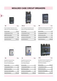
DS Page<br />
�ixed Overload & �ixed Short-circuit<br />
release with Normal Breaking Capacity<br />
Technical Data 2/9,2/10<br />
I-t Characteristic Curves 2/26<br />
MCCB Ordering Data 2/36<br />
Accessories Ordering Data 2/45<br />
Overall Dimensions 2/56,2/57<br />
DH Page<br />
Adjustable Overload & �ixed<br />
Short-circuit release with<br />
St<strong>and</strong>ard Breaking Capacity<br />
Technical Data 2/13,2/14<br />
I-t Characteristic Curves 2/29<br />
MCCB Ordering Data 2/38<br />
Accessories Ordering Data 2/48<br />
Overall Dimensions 2/61,2/62<br />
MOULDED CASE <strong>CIRCUIT</strong> <strong>BREAKERS</strong><br />
DTH..E Page<br />
�ixed Overload & �ixed Short-circuit<br />
release with High Breaking Capacity<br />
Technical Data 2/11<br />
I-t Characteristic Curves 2/27<br />
MCCB Ordering Data 2/36<br />
Accessories Ordering Data 2/46<br />
Overall Dimensions 2/58<br />
DL Page<br />
Adjustable Overload & �ixed<br />
Short-circuit release with<br />
High Breaking Capacity<br />
Technical Data 2/15<br />
I-t Characteristic Curves 2/30<br />
MCCB Ordering Data 2/39<br />
Accessories Ordering Data 2/49<br />
Overall Dimensions 2/63,2/64<br />
DG Page<br />
Adjustable Overload & �ixed Short-circuit<br />
release with Normal Breaking Capacity<br />
Technical Data 2/12<br />
I-t Characteristic Curves 2/28<br />
MCCB Ordering Data 2/37<br />
Accessories Ordering Data 2/47<br />
Overall Dimensions 2/59,2/60<br />
DTH Page<br />
Adjustable Overload & �ixed Short-circuit<br />
release (Conventional MCCBs) with<br />
High Breaking Capacity<br />
Technical Data 2/16,2/17<br />
I-t Characteristic Curves 2/31<br />
MCCB Ordering Data 2/40<br />
Accessories Ordering Data 2/50<br />
Overall Dimensions 2/65,2/66
DX..S Page<br />
Adjustable Overload & adjustable Shortcircuit<br />
with st<strong>and</strong>ard Breaking Capacity<br />
3 & 4 Pole<br />
Technical Data 2/18,2/19<br />
I-t Characteristic Curves 2/32-2/34<br />
MCCB Ordering Data 2/41<br />
Accessories Ordering Data 2/51,2/52<br />
Overall Dimensions 2/67-2/71<br />
DTH Instantaneous Page<br />
Instantaneous MCCBs<br />
Technical Data 2/24<br />
MCCB Ordering Data 2/44<br />
Accessories Ordering Data 2/55<br />
Overall Dimensions 2/78<br />
MOULDED CASE <strong>CIRCUIT</strong> <strong>BREAKERS</strong><br />
DX..H Page<br />
Adjustable Overload & adjustable Shortcircuit<br />
with high Breaking Capacity 3 & 4<br />
Pole<br />
Technical Data 2/20-2/22<br />
I-t Characteristic Curves 2/32-2/35<br />
MCCB Ordering Data 2/42<br />
Accessories Ordering Data 2/51-2/53<br />
Overall Dimensions 2/67-2/75<br />
D� Page<br />
�use Monitoring device<br />
Technical Data 2/25<br />
Ordering Data 2/44<br />
Accessories Ordering Data 2/55<br />
Overall Dimensions 2/79<br />
Wiring Diagram 2/79<br />
DM Page<br />
Motor protection MCCBs<br />
Technical Data 2/23<br />
MCCB Ordering Data 2/43<br />
Accessories Ordering Data 2/54<br />
Overall Dimensions 2/76,2/77<br />
Type 2 Co-ordination Chart 2/83<br />
2
2<br />
2/1<br />
MOULDED CASE <strong>CIRCUIT</strong> <strong>BREAKERS</strong><br />
L&T was the first company to introduce “Moulded case circuit Breakers (MCCBs)” in India. Over the years, it has developed &<br />
enhanced the products to growing requirements of market conditions.<br />
L&T MCCBs use latest technologies for circuit interruption under faults. These MCCBs comply with st<strong>and</strong>ards IS 13947, IEC 60947<br />
<strong>and</strong> EN 60947-2 <strong>and</strong> are certified at independent <strong>and</strong> approved test authorities.<br />
L&T offers a wide range of MCCBs with current ratings from 0.63A to 1600A in 3-Pole & 4-Pole versions & breaking capacity from<br />
6kA to 100kA. These MCCBs are available with Thermal-Magnetic as well as with Electronic release (above 125A in DX range).<br />
These MCCBs are available in �ixed or Drawout versions. They are also available in utilisation category ‘A’ or ‘B’.<br />
L&T MCCBs are complemented with a wide variety of internal <strong>and</strong> external accessories.<br />
APPLICATIONS<br />
Distribution �eeders Ideally suited for incoming <strong>and</strong> outgoing feeder circuits on distribution boards.<br />
Transformers Provide effective protection to distribution transformers as outgoing breakers on the LT side.<br />
DG Sets Used for protection <strong>and</strong> control of diesel generating sets against overloads <strong>and</strong> short circuits.<br />
AP�C Systems Suitable for controlling LT capacitors for power factor corrections.<br />
DC Loads Suitable for both AC as well as DC applications. Hence find application in protecting rectifier panels.<br />
UPS Used for UPS & Electronic equipment protection.<br />
Motors Specially designed MCCBs for Motor back-up protection provide Type-2 co-ordination (as per IEC 60947)<br />
in conjunction with suitably rated contactors <strong>and</strong> relays.<br />
�urnaces Suitable for high frequency systems upto 400Hz <strong>and</strong> can be used for control of high frequency furnaces.<br />
Also used in induction furnaces along with semiconductor fuses.<br />
WORKING PRINCIPLE<br />
L&T’s new range of MCCBs operate on “Current limiting” principle. This<br />
helps in very fast clearance (less than 10 mS) of short-circuit faults. This is<br />
achieved by –<br />
1. Quick opening of main contacts.<br />
2. Guiding the arc rapidly away from the contacts into the arcing chamber.<br />
3. Quick quenching of arc by using effective arc quenching devices.<br />
As a result peak short circuit current (I p ) is limited to cut-off current (I c ).<br />
Thus, I2t let through (proportional to the shaded area) is considerably<br />
reduced, resulting in lower thermal stresses in downstream equipments<br />
<strong>and</strong> connecting cables.
PRODUCT HIGHLIGHTS<br />
MOULDED CASE <strong>CIRCUIT</strong> <strong>BREAKERS</strong><br />
1. Operating mechanism is quick-make, quick-break <strong>and</strong> trip free. It is independent of manual speed of operation. Contacts cannot be<br />
‘teased’ into position, nor can the breaker be held closed under fault conditions.<br />
2. Clear indication of ‘ON’, ‘O��’ & ‘TRIP’ position.<br />
3. Suitable for both AC & DC applications.<br />
4. Terminals suitable for both copper & aluminium terminations.<br />
5. “Push to trip” facility to verify healthiness of mechanism.<br />
6. Wide range of site fittable accessories.<br />
7. Low let through energy.<br />
8. No load line bias in new range of MCCBs.<br />
9. Rotary operating mechanism has door interlock facility with an option of defeating interlock by an authorized person.<br />
10. Housing is made of heat resistant insulating material.<br />
11. Silver alloy contacts have long electrical life. The mechanism is so designed there is no arcing on the current carrying part of the<br />
contact. The strong “wipe action” of the contact system keeps the contact surface clear of oxide films.<br />
MOUNTING POSITION<br />
L&T’s new range of MCCB’s can be mounted up to 90 0 in any direction.<br />
MCCBs �OR MOTOR BACK-UP PROTECTION<br />
MCCBs are increasingly being used in motor application as<br />
a back- up protection device due to following advantages:<br />
✦ Low down time<br />
✦ Reduced running cost<br />
✦ No risking of single phasing<br />
✦ Availability of various accessories<br />
TYPICAL MOTOR �EEDER<br />
A typical motor protection scheme comprises a starter (contractor <strong>and</strong> thermal overload relay) <strong>and</strong> a short circuit protective device(SCPD)<br />
e.g.MCCB.<br />
Thermal overload relay provides close protection to the motor against single phasing <strong>and</strong> moderate overloads like stalling etc. Protection<br />
against higher overcurrents, beyond capability of the starter including short circuit faults is offered by MCCB.<br />
It is necessary to have proper discrimination between thermal overload relay <strong>and</strong> SCPD for any effective protection scheme. Type DM<br />
MCCBS are hence designed with instantaneous release to ensure proper discrimination.<br />
�USE MONITORING DEVICE<br />
L&T’s range of MCCBs also includes the �use Monitoring Device type ‘D�’, designed to monitor the operation of fuse.<br />
In the motor feeders, where Switch Disconnector �use units are used for motor backup protection, there is every possibility of only one of<br />
the three fuses blowing due to a fault, resulting in single phasing. This can be avoided by using �use Monitoring Device along with Switch<br />
Disconnector �use units of any fuse ratings (refer page 2/79 for connection diagram).<br />
2/2<br />
2
2<br />
Note : �or ordering information, refer pages 2/45 - 2/55<br />
2/3<br />
ACCESSORIES<br />
INTERNAL<br />
SHUNT RELEASE<br />
The shunt release provides remote tripping of the circuit breaker. The coil of<br />
shunt release is designed for short time as well as continuous operation (‘DX’<br />
range).<br />
The operation voltage is :<br />
85% to 110% of the rated voltage in AC<br />
75% to 125% of the rated voltage in DC<br />
Shunt release coil is short time rated, micro-switch is provided in the release to<br />
cut off the supply. Once the MCCB trips, this prevents burning of coil even if the<br />
supply to shunt coil is continuously fed.<br />
UNDER VOLTAGE RELEASE<br />
The under voltage release is used for protecting the installation against low voltage<br />
situation. The under voltage release is designed to operate when the voltage<br />
drops below a tripping threshold. This can also be used for remote tripping &<br />
electrical interlocking purpose.<br />
The tripping threshold is :<br />
35% to 70% of rated in AC<br />
35% to 70% of rated in DC<br />
Circuit breaker closing is possible only if the voltage exceeds 85% of the rated<br />
voltage.<br />
AUXILIARY CONTACT BLOCK<br />
The auxiliary contact block is used for remote signaling <strong>and</strong> control purposes.<br />
This consists of one or more than one potential free change-over contacts. It<br />
indicates the circuit breaker status- whether open or closed.<br />
TRIP ALARM CONTACT<br />
The trip alarm contact gives tripping indication once the MCCB trips. The potential<br />
free change- over contacts can be used for indication or for control circuit.
ELECTRICAL & MECHANICAL INTERLOCK<br />
PARALLELING MECHANISM<br />
ADAPTOR TERMINAL<br />
SHROUD<br />
Note : �or ordering information, refer pages 2/45 - 2/55<br />
ACCESSORIES<br />
EXTERNAL<br />
�OR ‘DX’ RANGE<br />
ANNUNCIATION UNIT<br />
Annunciation unit indicates the differential remote <strong>and</strong> local operating states<br />
like<br />
- Tripping by Overload release<br />
- Tripping be Short-circuit release<br />
- Early-alarm in the event that the Overload release setting is about to be<br />
exceeded.<br />
Annunciation unit has 1NO+1NC.<br />
RESIDUAL CURRENT OPERATED RELAYS<br />
These are factory fitted with adjustable rated fault current <strong>and</strong> delay time.<br />
MECHANICAL INTERLOCK<br />
�or mechanical interlocking of Two or Three MCCBs with Toggle or Rotary<br />
drive in the same distribution panel.<br />
PARALLELING MECHANISM<br />
�or simultaneous operation of two MCCBs mounted side by side, using a<br />
Rotary drive.<br />
SIDE WALL OPERATOR<br />
This is to be used for actuating the Breaker from the side of the control<br />
panel or for changing the Rotary movement by 90o<br />
WITHDRAWABLE UNIT<br />
Three position Withdrawable units are available for 3 <strong>and</strong> 4 PoleMCCBs<br />
(250A <strong>and</strong> above).<br />
PLUG-IN ADAPTORS<br />
3 pole ‘DX’ range of MCCBs (upto 250A) are also available with plug-in<br />
adaptor modules.<br />
ADAPTOR TERMINAL WITH SHROUD / SPREADER<br />
LINKS WITH BARRIERS<br />
Adaptor terminals / Spreader links can be connected to basic MCCBs to facilitate<br />
termination of higher size of cables / links.<br />
The barrier is made of material with high dielectric strength. It is used to ensure<br />
the electrical clearance between breaker terminals. It also prevents troubles<br />
caused by contact of conductive material to the terminals.<br />
Shrouds are used on both the sides of MCCB to provide additional safety <strong>and</strong><br />
are made of superior insulating material with good mechanical & electrical<br />
properties. The shrouds are designed for click-fit fixing & thus do not need any<br />
fixing hardware. Shroud prevents accidental contact to bare terminals.<br />
2/4<br />
2
2<br />
Note : �or ordering information, refer pages 2/45 - 2/55<br />
2/5<br />
ACCESSORIES<br />
EXTERNAL<br />
ROTARY OPERATING MECHANISM<br />
The circuit breaker has a toggle h<strong>and</strong>le operating mechanism, which also serves<br />
as swtiching position indicator – ON, O��, TRIP. But when the circuit breaker is<br />
installed in switchgear cubicles or distribution boards, it requires to be operated<br />
outside of the switchgear cubicles or distribution boards. The mechanism is<br />
designed for direct attachment to the MCCB <strong>and</strong> transforms the toggle h<strong>and</strong>le<br />
movement into a rotation. It facilitates operation of MCCB when the panel door is<br />
closed.<br />
IT’S �EATURES<br />
✦ Easy operation<br />
✦ Door interlock mechanism. It doesn’t allow the circuit breaker to be “ON”<br />
when the door of switchgear cubicles or distribution boards is open thus<br />
prevents the operator from an unsafe condition.<br />
✦ Door interlock defeat facility. This enables only authorized personnel to open<br />
the door with MCCB in ON condition for the purpose of inspection.<br />
�OR ‘DX’ RANGE<br />
REMOTE OPERATOR (MOTORISED)<br />
�or remote ‘ON’ <strong>and</strong> ‘O��’ of circuit breakers. Local switching by h<strong>and</strong> also<br />
possible.
G�1<br />
G�2<br />
G�11<br />
Note : �or ordering information, refer pages 2/45 - 2/55<br />
ACCESSORIES<br />
EXTERNAL<br />
EARTH �AULT MODULES (Type G�1, G�2, G�11)<br />
✦ Protection against earth faults<br />
✦ Built-in CBCT solid state design (G�11 to be used with external C.T.)<br />
✦ 10 – 50% adjustable current setting<br />
✦ 100 / 200 mS selectable trip time delay<br />
✦ Suitable for both 3 phase 3 wire & 3 phase 4 wire7 systems.<br />
✦ Built in test facility.<br />
✦ Potential free NO contact to trip MCCB through shunt trip.<br />
✦ Manual reset for positive fault acknowledgment<br />
(for Technical / Dimensional Details, refer page 2/80 <strong>and</strong> 2/81)<br />
S. S. ENCLOSURE<br />
Enclosure is made of CRCA material with superior quality paint for better<br />
adherence <strong>and</strong> to enhance weather resistance.<br />
MCCB mounted in Enclosure is ideally suited to be used as fuseless mains.<br />
�eatures of Enclosure<br />
✦ Isolable neutral<br />
✦ Earthing terminal<br />
✦ Positive indication of breaker position<br />
✦ Door lock <strong>and</strong> additional lock on enclosure prevents accidental switching of<br />
MCCB.<br />
(for Dimensional Details, refer page 2/82)<br />
2/6<br />
2
2<br />
Auxiliary Contacts<br />
2/7<br />
ACCESSORIES RANGE<br />
DS DTH..E DG DH DL DTH DX..S DX..H DM D�<br />
St<strong>and</strong>ard l l l l l l l l l l<br />
Early make - - - - - - l l - -<br />
General Trip alarm l l l l l l l l l l<br />
Contact alarm - - - - - - l l - -<br />
Separate contact alarm - - - - - - l l - -<br />
Under voltage release<br />
Shunt release<br />
Non-delayed l l l l l l l l l -<br />
Off-delayed - - - - - - l l - -<br />
Without early make aux. Contact l l l l l l l l l l<br />
With early make aux. Contact - - - - - - l l - -<br />
Remote operator - - - - - - l l - -<br />
Rotary operating mechanism l l l l l l l l l -<br />
Paralleling mechanism - - - - - - l l - -<br />
Mechanical interlock - - - - - - l l - -<br />
Castell lock - - - - - - l l - -<br />
Earth-fault module l l l l l l l l l -<br />
Earth-leakage module - - - - - - l l - -<br />
Plug-in module - - - - - - l l - -<br />
Withdrawable module - - - - - - l l - -<br />
Adaptor terminals - - - l l - - - l -<br />
Spreader terminals l - l l l - - - l -<br />
Enclosure l - l l - - - - - -<br />
l Available; – Not Available<br />
Note : Accessories mounting / location as per page 2/45 to 2/55
AUXILIARY CONTACT<br />
BLOCK<br />
Note : Except ‘DX’ Range<br />
UV RELEASE<br />
ACCESSORIES �OR MCCB<br />
ROTARY OPERATING<br />
MECHANISM<br />
TRIP ALARM<br />
CONTACT<br />
SHUNT RELEASE<br />
2/8<br />
2
2<br />
2/9<br />
TECHNICAL DATA - DS<br />
Type Designation DS 100 DS 125 DS 160<br />
Rated Uninterrupted current<br />
at 40 o C. - Ith (AC/DC) A 100 125 160<br />
Rated impulse withst<strong>and</strong> voltage - Uimp kV 8 8 8<br />
Rated operational voltage - Ue V AC 415 415 415<br />
V DC 250 250 250<br />
�requency Hz 50/60 50/60 50/60<br />
Rated insulation voltage - Ui V 690 690 690<br />
Operating Temperature °C -5 to +55 -5 to +55 -5 to +55<br />
Overvoltage category / pollution degree III/3 III/3 III/3<br />
Rated Short-circuit making capacity - Icm kA 17 17 32<br />
Rated ultimate S.C. breaking capacity - Icu<br />
at 415V ac kA 10 10 16<br />
Rated Service S.C. breaking capacity - Ics<br />
at 415V ac kA 50% 50% 50%<br />
Utilisation category A A A<br />
Mechanical life<br />
<strong>Electrical</strong> life<br />
Release Type Thermal-Magnetic Thermal-Magnetic Thermal-Magnetic<br />
Overload release setting �ixed �ixed �ixed<br />
Short Circuit release setting (+/- 20%) 9*In 9*In 8*In<br />
Weight kg 1.7 1.7 1.7<br />
Terminal capacity Cables mm 2 50 70 95<br />
Accessories<br />
As per st<strong>and</strong>ard IS 13947-2 / IEC 60947-2<br />
Links mm 16 22 22<br />
Auxiliary contacts (1NO+1NC) (1NO+1NC) (1NO+1NC)<br />
Shunt release y y y<br />
Under voltage release y y y<br />
Trip alarm contacts y y y<br />
Earth fault module y y y<br />
Rotary operating mechanism y y y
TECHNICAL DATA - DS<br />
Type Designation DS 200 DS 250 DS 400<br />
Rated Uninterrupted current<br />
at 40 o C. - Ith (AC/DC) A 200 250 400<br />
Rated impulse withst<strong>and</strong> voltage - Uimp kV 8 8 8<br />
Rated operational voltage - Ue V AC 415 415 415<br />
V DC 250 250 250<br />
�requency Hz 50/60 50/60 50/60<br />
Rated insulation voltage - Ui V 690 690 690<br />
Operating Temperature °C -5 to +55 -5 to +55 -5 to +55<br />
Overvoltage category / pollution degree III/3 III/3 III/3<br />
Rated Short-circuit making capacity - Icm kA 32 52.5 52.5<br />
Rated ultimate S.C. breaking capacity - Icu<br />
at 415V ac kA 16 25 25<br />
Rated Service S.C. breaking capacity - Ics<br />
at 415V ac kA 50% 50% 50%<br />
Utilisation category A A A<br />
Mechanical life<br />
<strong>Electrical</strong> life<br />
Release Type Thermal-Magnetic Thermal-Magnetic Thermal-Magnetic<br />
Overload release setting �ixed �ixed �ixed<br />
Short Circuit release setting (+/- 20%) 6*In 6*In 6*In<br />
Weight kg 2.4 5 5<br />
Terminal capacity Cables mm 2 150 300 300<br />
Accessories<br />
As per st<strong>and</strong>ard IS 13947-2 / IEC 60947-2<br />
Links mm 30 40 40<br />
Auxiliary contacts (1NO+1NC) (2NO+2NC) (2NO+2NC)<br />
Shunt release y y y<br />
Under voltage release y y y<br />
Trip alarm contacts y y y<br />
Earth fault module y y y<br />
Rotary operating mechanism y y y<br />
2/10<br />
2
2<br />
2/11<br />
TECHNICAL DATA - DTH...E<br />
Type Designation DTH 200E DTH 250E DTH 400E DTH 630E DTH 800E<br />
Rated Uninterrupted current<br />
at 40o C. - Ith (AC/DC) A 200 250 400 630 800<br />
Rated impulse withst<strong>and</strong> voltage - Uimp kV –– 8 8 8 8<br />
Rated operational voltage - Ue V 415 415 415 415 415<br />
V DC 250 250 250 250 250<br />
�requency Hz 50/60 50/60 50/60 50/60 50/60<br />
Rated insulation voltage - Ui V 600 600 600 600 600<br />
Operating Temperature °C -5 to +55 -5 to +55 -5 to +55 -5 to +55 -5 to +55<br />
Overvoltage category / pollution degree III/3 III/3 III/3 III/3 III/3<br />
Rated Short-circuit making capacity - Icm kA – 105 105 105 105<br />
Rated ultimate S.C. breaking capacity - Icu<br />
at 660V ac kA – 10 10 10 10<br />
at 550V ac kA – 25 25 25 25<br />
at 500V ac kA – 35 35 35 35<br />
at 415V ac kA 35 50 50 50 50<br />
at 380V ac kA – 50 50 50 50<br />
at 240V ac kA – 60 60 60 60<br />
Rated Service S.C. breaking capacity - Ics<br />
at 415V ac kA – 50% 50% 50% 50%<br />
DC Breaking capacity at 250 V, L/R
TECHNICAL DATA - DG<br />
Type Designation DG 125 DG 200 DG 250 DG 400<br />
Rated Uninterrupted current<br />
at 40 o C. - Ith (AC/DC) A 125 200 250 400<br />
Rated impulse withst<strong>and</strong> voltage - Uimp kV 8 8 8 8<br />
Rated operational voltage - Ue V AC 415 415 415 415<br />
V DC 250 250 250 250<br />
�requency Hz 50/60 50/60 50/60 50/60<br />
Rated insulation voltage - Ui V 690 690 690 690<br />
Operating Temperature °C -5 to +55 -5 to +55 -5 to +55 -5 to +55<br />
Overvoltage category / pollution degree III/3 III/3 III/3 III/3<br />
Rated ultimate S.C. breaking capacity - Icu<br />
at 415V ac kA 10 16 25 25<br />
Rated Service S.C. breaking capacity - Ics<br />
at 415V ac kA 75% 75% 75% 75%<br />
Utilisation category A A A A<br />
Mechanical life<br />
<strong>Electrical</strong> life<br />
Release Type Thermal-Magnetic Thermal-Magnetic Thermal-Magnetic Thermal-Magnetic<br />
Overload release setting 80-100% 80-100% 80-100% 80-100%<br />
Short Circuit release setting (+/- 20%) 4*In 4*In 4*In 4*In<br />
Weight kg 1.8 2.4 5 5<br />
Terminal capacity Cables mm 2 70 150 300 300<br />
Accessories<br />
As per st<strong>and</strong>ard IS 13947-2 / IEC 60947-2<br />
Links mm 22 30 40 40<br />
Auxiliary contacts (1NO+1NC) (1NO+1NC) (2NO+2NC) (2NO+2NC)<br />
Shunt release y y y y<br />
Under voltage release y y y y<br />
Trip alarm contacts y y y y<br />
Earth fault module y y y y<br />
Rotary operating mechanism y y y y<br />
2/12<br />
2
2<br />
2/13<br />
TECHNICAL DATA - DH<br />
Type Designation DH 100 DH 125 DH 160 DH 200<br />
Rated Uninterrupted current<br />
at 40o C. - Ith (AC/DC) A 100 125 160 200<br />
Rated impulse withst<strong>and</strong> voltage - Uimp kV 8 8 8 8<br />
Rated operational voltage - Ue V 415 415 415 415<br />
V DC 250 250 250 250<br />
�requency Hz 50/60 50/60 50/60 50/60<br />
Rated insulation voltage - Ui V 690 690 690 690<br />
Operating Temperature °C -5 to +55 -5 to +55 -5 to +55 -5 to +55<br />
Overvoltage category / pollution degree III/3 III/3 III/3 III/3<br />
Rated Short-circuit making capacity - Icm kA 52.5 73.5 73.5 73.5<br />
Rated ultimate S.C. breaking capacity - Icu<br />
at 660V ac kA 5 7 7 7<br />
at 550V ac kA 12 18 18 18<br />
at 500V ac kA 18 25 25 25<br />
at 415V ac kA 25 35 35 35<br />
at 380V ac kA 25 35 35 35<br />
at 240V ac kA 50 60 60 60<br />
Rated Service S.C. breaking capacity - Ics<br />
at 415V ac kA 100% 75% 75% 50%<br />
DC Breaking capacity at 250 V, L/R
TECHNICAL DATA - DH<br />
Type Designation DH 250 DH 400 DH 630<br />
Rated Uninterrupted current<br />
at 40o C. - Ith (AC/DC) A 250 400 630<br />
Rated impulse withst<strong>and</strong> voltage - Uimp kV 8 8 8<br />
Rated operational voltage - Ue V 415 415 415<br />
V DC 250 250 250<br />
�requency Hz 50/60 50/60 50/60<br />
Rated insulation voltage - Ui V 690 690 690<br />
Operating Temperature °C -5 to +55 -5 to +55 -5 to +55<br />
Overvoltage category / pollution degree III/3 III/3 III/3<br />
Rated Short-circuit making capacity - Icm kA 73.5 73.5 73.5<br />
Rated ultimate S.C. breaking capacity - Icu<br />
at 660V ac kA 7 7 7<br />
at 550V ac kA 18 18 18<br />
at 500V ac kA 25 25 25<br />
at 415V ac kA 35 35 35<br />
at 380V ac kA 35 35 35<br />
at 240V ac kA 60 60 60<br />
Rated Service S.C. breaking capacity - Ics<br />
at 415V ac kA 75% 75% 75%<br />
DC Breaking capacity at 250 V, L/R
2<br />
2/15<br />
TECHNICAL DATA - DL<br />
Type Designation DL 100 DL 160 DL 250 DL 400<br />
Rated Uninterrupted current<br />
at 40o C. - Ith (AC/DC) A 100 160 250 400<br />
Rated impulse withst<strong>and</strong> voltage - Uimp kV 8 8 8 8<br />
Rated operational voltage - Ue V 415 415 415 415<br />
V DC 250 250 250<br />
�requency Hz 50/60 50/60 50/60 50/60<br />
Rated insulation voltage - Ui V 690 690 690 690<br />
Operating Temperature °C -5 to +55 -5 to +55 -5 to +55 -5 to +55<br />
Overvoltage category / pollution degree III/3 III/3 III/3 III/3<br />
Rated Short-circuit making capacity - Icm kA 105 105 105 105<br />
Rated ultimate S.C. breaking capacity - Icu<br />
at 660V ac kA 10 10 10 10<br />
at 550V ac kA 25 25 25 25<br />
at 500V ac kA 35 35 35 35<br />
at 415V ac kA 50 50 50 50<br />
at 380V ac kA 50 50 50 50<br />
at 240V ac kA 65 50 65 65<br />
Rated Service S.C. breaking capacity - Ics<br />
at 415V ac kA 100% 100% 100% 100%<br />
DC Breaking capacity at 250 V, L/R
TECHNICAL DATA - DTH<br />
Type Designation DTH 100 DTH 200<br />
Rated Uninterrupted current<br />
at 40o C - Ith (AC/DC) A 100 200<br />
Rated impulse withst<strong>and</strong> voltage - Uimp kV –– ––<br />
Rated operational voltage - Ue V 415 415<br />
V DC 250 250<br />
�requency Hz 50/60 50/60<br />
Rated insulation voltage - Ui V 600 600<br />
Operating Temperature °C -5 to +55 -5 to +55<br />
Overvoltage category / pollution degree III/3 III/3<br />
Rated ultimate S.C. breaking capacity - P1<br />
at 415V ac kA 10 35<br />
DC Breaking capacity at 250 V, L/R
2<br />
2/17<br />
TECHNICAL DATA - DTH<br />
Type Designation DTH 250 DTH 400 DTH 630 DTH 800<br />
Rated Uninterrupted current<br />
at 40o C. - Ith (AC/DC) A 250 400 630 800<br />
Rated impulse withst<strong>and</strong> voltage - Uimp kV 8 8 8 8<br />
Rated operational voltage - Ue V 415 415 415 415<br />
V DC 250 250 250 250<br />
�requency Hz 50/60 50/60 50/60 50/60<br />
Rated insulation voltage - Ui V 600 600 600 600<br />
Operating Temperature °C -5 to +55 -5 to +55 -5 to +55 -5 to +55<br />
Overvoltage category / pollution degree III/3 III/3 III/3 III/3<br />
Rated Short-circuit making capacity - Icm kA 105 105 105 105<br />
Rated ultimate S.C. breaking capacity - Icu<br />
at 660V ac kA 10 10 10 10<br />
at 550V ac kA 25 25 25 25<br />
at 500V ac kA 35 35 35 35<br />
at 415V ac kA 50 50 50 50<br />
at 380V ac kA 50 50 50 50<br />
at 240V ac kA 60 60 60 60<br />
Rated Service S.C. breaking capacity - Ics<br />
at 415V ac kA 50% 50% 50% 50%<br />
DC Breaking capacity at 250 V, L/R
TECHNICAL DATA - DX..S (3/4 POLE)<br />
Type Designation DX 100S DX 125S DX 160S DX 200S<br />
Rated Uninterrupted current<br />
at 40o C. - Ith (AC/DC) A 100 125 160 200<br />
Rated impulse withst<strong>and</strong> voltage - Uimp kV 8 8 8 8<br />
Rated operational voltage - Ue V 415 415 415 415<br />
V DC 440 440 440 440<br />
�requency Hz 50/60 50/60 50/60 50/60<br />
Rated insulation voltage - Ui V 690 690 690 690<br />
Operating Temperature °C -5 to +55 -5 to +55 -5 to +55 -5 to +55<br />
Overvoltage category / pollution degree III/3 III/3 III/3 III/3<br />
Rated Short-circuit making capacity - Icm kA 94.5 94.5 94.5 94.5<br />
Rated ultimate S.C. breaking capacity - Icu<br />
at 690V ac kA 6 6 6 6<br />
at 500V ac kA 12 12 12 12<br />
at 415V ac kA 35 35 35 35<br />
at 230V ac<br />
Rated Service S.C.<br />
kA 45 45 45 45<br />
breaking capacity - Ics (of Icu) kA 100% 100% 100% 100%<br />
DC Breaking capacity at 440 V kA 20 20 20 20<br />
Utilisation category A A A A<br />
Rated short-time withst<strong>and</strong> current Icw (1 Sec)kA - - - -<br />
Mechanical life Ops. 20000 20000 20000 20000<br />
<strong>Electrical</strong> life (AC3, 400V) Ops. 6000 6000 6000 3500<br />
Release Type Thermal-Magnetic Thermal-Magnetic Thermal-Magnetic Thermal-Magnetic<br />
Overload release setting 80-100% 80-100% 80-100% 80-100%<br />
Short Circuit release setting 6-12*In 6-12*In 6-12*In 6-12*In<br />
Mechanical Shock resistance g 20 20 20 20<br />
Weight (3 - Pole) kg 1.7 1.7 1.7 1.7<br />
(4 - Pole)<br />
Accessories<br />
kg 1.7 1.7 1.7 1.7<br />
Auxiliary contacts y y y y<br />
Shunt release y y y y<br />
Under voltage release y y y y<br />
Trip indicating auxiliary contacts y y y y<br />
Earth fault module y y y y<br />
Rotary operating mechanism y y y y<br />
Residual-current protection module y y y y<br />
Remote operator y y y y<br />
Withdrawable unit - - - -<br />
Plug-in module y y y y<br />
Mechanical interlock y y y y<br />
Paralleling mechanism<br />
Load monitoring<br />
y y y y<br />
2/18<br />
2
2<br />
2/19<br />
TECHNICAL DATA - DX..S (3/4 POLE)<br />
Type Designation DX 250S DX 400S DX 630S<br />
Rated Uninterrupted current<br />
at 40o C. - Ith (AC/DC) A 250 400 630<br />
Rated impulse withst<strong>and</strong> voltage - Uimp kV 8 8 8<br />
Rated operational voltage - Ue V 415 415 415<br />
V DC 440 – –<br />
�requency Hz 50/60 50/60 50/60<br />
Rated insulation voltage - Ui V 690 690 690<br />
OperatingTemperature °C -5 to +55 -5 to +55 -5 to +55<br />
Overvoltage category / pollution degree III/3 III/3 III/3<br />
Rated Short-circuit making capacity - Icm kA 94.5 220 220<br />
Rated ultimate S.C. breaking capacity - Icu<br />
at 690V ac kA 6 25 25<br />
at 500V ac kA 12 42 42<br />
at 415V ac kA 35 65 65<br />
at 230V ac<br />
Rated Service S.C.<br />
kA 45 100 100<br />
breaking capacity - Ics (of Icu) kA 100% 50% 50%<br />
DC Breaking capacity at 440 V kA 20 - -<br />
Utilisation category A A / B A / B<br />
Rated short-time withst<strong>and</strong> current Icw (1 Sec)kA - 8 8<br />
Mechanical life Ops. 20000 20000 20000<br />
<strong>Electrical</strong> life (AC3, 400V) Ops. 3500 1250 1250<br />
Release Type Thermal-Magnetic Electronic Electronic<br />
Overload release setting 80-100% 50-100% 50-100%<br />
Short Circuit release setting 6-12*In 2-12*In 2-12*In<br />
Mechanical Shock resistance g 20 20 20<br />
Weight (3 - Pole) kg 1.7 9.1 9.1<br />
(4 - Pole)<br />
Accessories<br />
kg 1.7 11.9 11.9<br />
Auxiliary contacts y y y<br />
Shunt release y y y<br />
Under voltage release y y y<br />
Trip indicating auxiliary contacts y y y<br />
Earth fault module y y y<br />
Rotary operating mechanism y y y<br />
Residual-current protection module y y y<br />
Remote operator y y y<br />
Withdrawable unit - y y<br />
Mechanical interlock y y y<br />
Paralleling mechanism<br />
Load monitoring<br />
y y y
TECHNICAL DATA - DX..H (3/4 POLE)<br />
Type Designation DX 100H DX 125H DX 160H DX 200H<br />
Rated Uninterrupted current<br />
at 40 ° C. - Ith (AC/DC) A 100 125 160 200<br />
Rated impulse withst<strong>and</strong> voltage - Uimp kV 8 8 8 8<br />
Rated operational voltage - Ue V 415 415 415 415<br />
V DC 440 440 440 440<br />
�requency Hz 50/60 50/60 50/60 50/60<br />
Rated insulation voltage - Ui V 690 690 690 690<br />
Operating Temperature °C -5 to +55 -5 to +55 -5 to +55 -5 to +55<br />
Overvoltage category / pollution degree III/3 III/3 III/3 III/3<br />
Rated Short-circuit making capacity - Icm kA 220 550 220 220<br />
Rated ultimate S.C. breaking capacity - Icu<br />
at 690V ac kA 8 8 8 8<br />
at 500V ac kA 20 20 20 20<br />
at 415V ac kA 65 65 65 65<br />
at 230V ac<br />
Rated Service S.C.<br />
kA 100 100 100 100<br />
breaking capacity - Ics (of Icu) kA 75% 75% 75% 75%<br />
DC Breaking capacity at 440 V kA 25 25 25 25<br />
Utilisation category A A A A<br />
Rated short-time withst<strong>and</strong> current Icw (1 Sec) kA - - - -<br />
Mechanical life Ops. 20000 20000 20000 20000<br />
<strong>Electrical</strong> life (AC3, 400V) Ops. 6000 6000 6000 3500<br />
Release Type Thermal-Magnetic Thermal-Magnetic Thermal-Magnetic Thermal-Magnetic<br />
Overload release setting 80-100% 80-100% 80-100% 80-100%<br />
Short Circuit release setting 6-12*In 6-12*In 6-12*In 6-12*In<br />
Mechanical Shock resistance g 20 20 20 20<br />
Weight (3 - Pole) kg 1.7 1.7 1.7 1.7<br />
(4 - Pole)<br />
Accessories<br />
kg 1.7 1.7 1.7 1.7<br />
Auxiliary contacts y y y y<br />
Shunt release y y y y<br />
Under voltage release y y y y<br />
Trip indicating auxiliary contacts y y y y<br />
Earth fault module y y y y<br />
Rotary operating mechanism y y y y<br />
Residual-current protection module y y y y<br />
Remote operator y y y y<br />
Withdrawable unit - - - -<br />
Plug-in module y y y y<br />
Mechanical interlock y y y y<br />
Paralleling mechanism<br />
Load monitoring<br />
y y y y<br />
2/20<br />
2
2<br />
2/21<br />
TECHNICAL DATA - DX..H (3/4 POLE)<br />
Type Designation DX 250H DX 400H DX 630H DX 800H<br />
Rated Uninterrupted current<br />
at 40 ° C. - Ith (AC/DC) A 250 400 630 800<br />
Rated impulse withst<strong>and</strong> voltage - Uimp kV 8 8 8 8<br />
Rated operational voltage - Ue V 415 415 415 415<br />
V DC 440 – – –<br />
�requency Hz 50/60 50/60 50/60 50/60<br />
Rated insulation voltage - Ui V 690 690 690 690<br />
Operating Temperature °C -5 to +55 -5 to +55 -5 to +55 -5 to +55<br />
Overvoltage category / pollution degree III/3 III/3 III/3 III/3<br />
Rated Short-circuit making capacity - Icm kA 220 440 440 275<br />
Rated ultimate S.C. breaking capacity - Icu<br />
at 690V ac kA 8 30 30 25<br />
at 500V ac kA 20 65 65 45<br />
at 415V ac kA 65 100 100 65<br />
at 230V ac<br />
Rated Service S.C.<br />
kA 100 200 200 100<br />
breaking capacity - Ics (of Icu) kA 75% 50% 50% 75%<br />
DC Breaking capacity at 440 V kA 25 - - -<br />
Utilisation category A A / B A B<br />
Rated short-time withst<strong>and</strong> current Icw (1 Sec) kA - 8 8 15 (0.3 S)<br />
Mechanical life Ops. 20000 20000 20000 2500<br />
<strong>Electrical</strong> life (AC3, 400V) Ops. 3500 5000 5000 500 (AC1)<br />
Release Type Thermal-Magnetic Electronic Electronic Electronic<br />
Overload release setting 80-100% 50-100% 50-100% 50-100%<br />
Short Circuit release setting 6-12*In 2-12*In 2-12*In 2-12*In<br />
Mechanical Shock resistance g 20 20 20 20<br />
Weight (3 - Pole) kg 1.7 9.1 9.1 20.4<br />
(4 - Pole)<br />
Accessories<br />
kg 1.7 11.9 11.9 26.4<br />
Auxiliary contacts y y y y<br />
Shunt release y y y y<br />
Under voltage release y y y y<br />
Trip indicating auxiliary contacts y y y y<br />
Earth fault module y y y y<br />
Rotary operating mechanism y y y y<br />
Residual-current protection module y y y -<br />
Remote operator y y y y<br />
Withdrawable unit - y y y<br />
Mechanical interlock y y y y<br />
Paralleling mechanism y y y -<br />
Load monitoring y
TECHNICAL DATA - DX..H (3/4 POLE)<br />
Type Designation DX 1000H DX 1250H DX 1600H<br />
Rated Uninterrupted current<br />
at 40 ° C. - Ith (AC/DC) A 1000 1250 1600<br />
Rated impulse withst<strong>and</strong> voltage - Uimp kV 8 8 8<br />
Rated operational voltage - Ue V 415 415 415<br />
�requency Hz 50/60 50/60 50/60<br />
Rated insulation voltage - Ui V 690 690 690<br />
Operating Temperature °C -5 to +55 -5 to +55 -5 to +55<br />
Overvoltage category / pollution degree III/3 III/3 III/3<br />
Rated Short-circuit making capacity - Icm kA 275 275 275<br />
Rated ultimate S.C. breaking capacity - Icu<br />
at 690V ac kA 25 25 45<br />
at 500V ac kA 45 45 65<br />
at 415V ac kA 65 65 85<br />
at 230V ac<br />
Rated Service S.C.<br />
kA 100 100 125<br />
breaking capacity - Ics (of Icu) kA 75% 75% 75%<br />
Utilisation category B B B<br />
Rated short-time withst<strong>and</strong> current Icw (1 Sec) kA 15 (0.3 S) 15 (0.3 S) 20 (0.3 S)<br />
Mechanical life Ops. 2500 2500 2500<br />
<strong>Electrical</strong> life (AC3, 400V) Ops. 500 (AC1) 500 (AC1) 500 (AC1)<br />
Release Type Electronic Electronic Electronic<br />
Overload release setting 50-100% 50-100% 50-100%<br />
Short Circuit release setting 2-12*In 2-12*In 2-12*In<br />
Mechanical Shock resistance g 20 20 20<br />
Weight (3 - Pole) kg 20.4 20.4 20.4<br />
(4 - Pole)<br />
Accessories<br />
kg 26.4 26.4 26.4<br />
Auxiliary contacts y y y<br />
Shunt release y y y<br />
Under voltage release y y y<br />
Trip indicating auxiliary contacts y y y<br />
Earth fault module y y y<br />
Rotary operating mechanism y y y<br />
Residual-current protection module - - -<br />
Remote operator y y y<br />
Withdrawable unit y y y<br />
Side wall operator - - -<br />
Mechanical interlock y y y<br />
Load monitoring y y y<br />
2/22<br />
2
2<br />
2/23<br />
TECHNICAL DATA - DM<br />
Type Designation DM 16 DM 100 DM 160 DM 250 DM 400<br />
Rated Uninterrupted current<br />
at 40o C. - Ith (AC/DC) A 16 70 160 250 400<br />
Rated impulse withst<strong>and</strong> voltage - Uimp kV 8 8 8 8 8<br />
Rated operational voltage - Ue V 415 415 415 415 415<br />
�requency Hz 50/60 50/60 50/60 50/60 50/60<br />
Rated insulation voltage - Ui V 690 690 690 690 690<br />
Operating Temperature °C -5 to +55 -5 to +55 -5 to +55 -5 to +55 -5 to +55<br />
Overvoltage category / pollution degree III/3 III/3 III/3 III/3 III/3<br />
Rated Short-circuit making capacity - Icm kA 105 105 105 105 105<br />
Rated ultimate S.C. breaking capacity - Icu<br />
at 660V ac kA 10 10 10 10 10<br />
at 550V ac kA 25 25 25 25 25<br />
at 500V ac kA 35 35 35 35 35<br />
at 415V ac kA 50 50 50 50 50<br />
at 380V ac kA 50 50 50 50 50<br />
at 240V ac kA 85 85 85 85 85<br />
Rated Service S.C.<br />
breaking capacity - Ics at 415V ac kA 100% 100% 100% 100% 100%<br />
Utilisation category A A A A A<br />
Mechanical life<br />
<strong>Electrical</strong> life<br />
Release Type Magnetic Magnetic Magnetic Magnetic Magnetic<br />
Short Circuit release setting (+/- 20%) 12*In 12*In 12*In 12*In 12*In<br />
Weight kg 1 1.65 4.8 5.5 5.5<br />
Terminal capacity Cables mm 2 10 50 185 300 300<br />
Accessories<br />
As per st<strong>and</strong>ard IS 13947-2 / IEC 60947-2<br />
Links mm - 16 36 40 40<br />
Auxiliary contacts 1 NO + 1 NC 1 NO + 1 NC 1 NO + 1 NC 2 NO + 2 NC 2 NO + 2 NC<br />
Shunt release y y y y y<br />
Under voltage release – y y y y<br />
Trip alarm contacts y y y y y<br />
Rotary operating mechanism y y y y y
TECHNICAL DATA - DTH 800 INST.<br />
Type Designation DTH 800 INST.<br />
Rated Uninterrupted current<br />
at 40o C. - Ith (AC/DC) A 800<br />
Rated impulse withst<strong>and</strong> voltage - Uimp kV 8<br />
Rated operational voltage - Ue V 415<br />
�requency Hz 50/60<br />
Rated insulation voltage - Ui V 600<br />
Operating Temperature °C -5 to +55<br />
Overvoltage category / pollution degree III/3<br />
Rated ultimate S.C. breaking capacity - Icu<br />
at 415V ac kA 50<br />
Rated Service S.C. breaking capacity - Ics<br />
at 415V ac (of Icu) kA 50%<br />
Utilisation category A<br />
Mechanical life Ops. 8000<br />
<strong>Electrical</strong> life Ops. 1200<br />
Release Type Magnetic<br />
Short Circuit release setting (+/- 20%) 360A, 550A, 850A, 1050A<br />
Weight kg 10<br />
Terminal capacity Cables mm 2 2*240<br />
Accessories<br />
Links mm 40 (Max. 15 thk.)<br />
Auxiliary contacts y<br />
Shunt release y<br />
Under voltage release y<br />
Trip alarm contacts y<br />
Earth fault module y<br />
Rotary operating mechanism y<br />
2/24<br />
2
2<br />
2/25<br />
TECHNICAL DATA - D�<br />
Type Designation D�<br />
Rated Uninterrupted current<br />
at 40o C. - Ith (AC/DC) A 1<br />
Rated impulse withst<strong>and</strong> voltage - Uimp kV 8<br />
Rated operational voltage - Ue V 415<br />
�requency Hz 50/60<br />
Rated insulation voltage - Ui V 600<br />
Operating Temperature °C -5 to +55<br />
Overvoltage category / pollution degree III/3<br />
Rated ultimate S.C. breaking capacity - Icu<br />
at 415V ac kA 50<br />
Magnetic Threshold A 2<br />
Mechanical life Ops. 10000<br />
<strong>Electrical</strong> life Ops. 6000<br />
Overload release setting (�ixed) A 1<br />
Weight kg 0.65<br />
Terminal capacity Without lugs mm 2 4<br />
Accessories<br />
With lugs mm 2 16<br />
Auxiliary contact 1 CO, 5A-250V<br />
Shunt release y<br />
Auxiliary contact y<br />
Trip alarm contacts y
I-t CHARACTERISTIC CURVES<br />
MCCB - TYPE DS<br />
DS 100 DS 125/160<br />
DS 200 DS 250/400<br />
Note: Short Circuit tripping values indicated as multiple of rated current<br />
2/26<br />
2
2<br />
2/27<br />
I-t CHARACTERISTIC CURVES<br />
MCCB - TYPE DTH...E<br />
DTH 200E DTH 250E<br />
DTH 400E DTH 630E DTH 800E<br />
Note: Short Circuit tripping values indicated as multiple of rated current
I-t CHARACTERISTIC CURVES<br />
MCCB - TYPE DG<br />
DG 125 DG 160<br />
DG 200 DG 250/400<br />
Note: Short Circuit tripping values indicated as multiple of rated current<br />
2/28<br />
2
2<br />
2/29<br />
I-t CHARACTERISTIC CURVES<br />
MCCB - TYPE DH<br />
DH 100/125 DH 160<br />
DH 200 DH 250/400/630<br />
Note: Short Circuit tripping values indicated as multiple of rated current
I-t CHARACTERISTIC CURVES<br />
MCCB - TYPE DL<br />
DL 100 DL 160<br />
DL 250/400<br />
Note: Short Circuit tripping values indicated as multiple of rated current<br />
2/30<br />
2
2<br />
2/31<br />
I-t CHARACTERISTIC CURVES<br />
MCCB - TYPE DTH<br />
DTH 100 DTH 200 DTH 250<br />
DTH 400 DTH 630 DTH 800<br />
Note: Short Circuit tripping values indicated as multiple of rated current
I-t CHARACTERISTIC CURVES<br />
DX 100-250 S/H (3/4 POLE)<br />
Note: Short Circuit tripping values indicated as multiple of rated current<br />
2/32<br />
2
2<br />
2/33<br />
125 250<br />
I-t CHARACTERISTIC CURVES<br />
DX 400 S/H (3/4 POLE)<br />
Note: Short Circuit tripping values indicated as multiple of rated current
I-t CHARACTERISTIC CURVES<br />
DX 630 S/H (3/4 POLE)<br />
Note: Short Circuit tripping values indicated as multiple of rated current<br />
2/34<br />
2
2<br />
2/35<br />
I-t CHARACTERISTIC CURVES<br />
DX 800-1600 H (3/4 POLE)<br />
DX 800 H DX 1000 H<br />
DX 1250 H DX 1600 H<br />
Note: Short Circuit tripping values indicated as multiple of rated current
ORDERING DATA - DS RANGE<br />
MCCB Rating Current Breaking Overload Short-Circuit Std. Catalogue No. Ordering<br />
(A) Rating (A) Capacity, Icu(kA) Setting (A) Setting Pack Suffix<br />
DS 100 100 16 10 16 9*In 12 SL97917 OOOO<br />
20 10 20 9*In 12 SL97918 OOOO<br />
25 10 25 9*In 12 SL97919 OOOO<br />
32 10 32 9*In 12 SL97920 OOOO<br />
40 10 40 9*In 12 SL97921 OOOO<br />
50 10 50 9*In 12 SL97922 OOOO<br />
63 10 63 9*In 12 SL97923 OOOO<br />
80 10 80 9*In 12 SL97924 OOOO<br />
100 10 100 9*In 12 SL97925 OOOO<br />
DS 125 125 125 10 125 9*In 12 SL97929 OOOO<br />
DS 160 160 160 16 160 9*In 12 SL97930 OOOO<br />
DS 200 200 200 16 200 6*In 12 SL97931 OOOO<br />
DS 250 250 250 25 250 6*In 1 SL94541 OOOO<br />
DS 400 320 320 25 320 6*In 1 SL94542 OOOO<br />
400 400 25 400 6*In 1 SL94543 OOOO<br />
ORDERING DATA - DTH...E RANGE<br />
MCCB Rating Current Breaking Overload Short-Circuit Std. Catalogue No. Ordering<br />
(A) Rating (A) Capacity, Icu(kA) Setting (A) Setting Pack Suffix<br />
DTH 200E 200 200 35 200 8*In 1 ST 30513 OOOO<br />
DTH 250E 250 250 50 250 3-8*In 1 ST 30543 OOOO<br />
DTH 400E 400 400 50 400 3-8*In 1 ST 30545 OOOO<br />
DTH 630E 630 630 50 630 3-8*In 1 ST 30514 OOOO<br />
DTH 800E 800 800 50 800 3-8*In 1 ST 30546 OOOO<br />
2/36<br />
2
2<br />
2/37<br />
ORDERING DATA - DG RANGE<br />
MCCB Rating Current Breaking Overload Short-Circuit Std. Catalogue No. Ordering<br />
(A) Rating (A) Capacity, Icu(kA) Setting (A) Setting Pack Suffix<br />
DG 125 125 16 10 12 - 16 6*In 1 SL97941 OOOO<br />
20 10 16 - 20 6*In 1 SL97942 OOOO<br />
25 10 20 - 25 6*In 1 SL97943 OOOO<br />
32 10 25 - 32 6*In 1 SL97944 OOOO<br />
40 10 32 - 40 6*In 1 SL97945 OOOO<br />
50 10 40 - 50 6*In 1 SL97946 OOOO<br />
63 10 50 - 63 4*In 1 SL97947 OOOO<br />
80 10 63 - 80 4*In 1 SL97948 OOOO<br />
100 10 80 - 100 4*In 1 SL97949 OOOO<br />
125 10 100 - 125 4*In 1 SL97950 OOOO<br />
DG 200 200 160 16 128 - 160 4*In 1 SL97951 OOOO<br />
200 16 160 - 200 4*In 1 SL97953 OOOO<br />
DG 250 250 250 25 200 - 250 4*In 1 SL97957 OOOO<br />
DG 400 400 320 25 250 - 320 4*In 1 SL97958 OOOO<br />
400 25 320 - 400 4*In 1 SL97959 OOOO
ORDERING DATA - DH RANGE<br />
MCCB Rating Current Breaking Overload Short-Circuit Std. Catalogue No. Ordering<br />
(A) Rating (A) Capacity, Icu(kA) Setting (A) Setting Pack Suffix<br />
DH 100 100 16 25 12 - 16 9*In 1 SL 97201 OOOO<br />
20 25 16 - 20 9*In 1 SL 97202 OOOO<br />
25 25 20 - 25 9*In 1 SL 97203 OOOO<br />
32 25 25 - 32 9*In 1 SL 97204 OOOO<br />
40 25 32 - 40 9*In 1 SL 97205 OOOO<br />
50 25 40 - 50 9*In 1 SL 97206 OOOO<br />
63 25 50 - 63 9*In 1 SL 97207 OOOO<br />
80 25 63 - 80 9*In 1 SL 97208 OOOO<br />
100 25 80 - 100 9*In 1 SL 97209 OOOO<br />
DH 125 125 16 35 12 - 16 9*In 1 SL 98556 OOOO<br />
20 35 16 - 20 9*In 1 SL 98557 OOOO<br />
25 35 20 - 25 9*In 1 SL 98558 OOOO<br />
32 35 25 - 32 9*In 1 SL 98559 OOOO<br />
40 35 32 - 40 9*In 1 SL 98560 OOOO<br />
50 35 40 - 50 9*In 1 SL 98561 OOOO<br />
63 35 50 - 63 9*In 1 SL 98562 OOOO<br />
80 35 63 - 80 9*In 1 SL 98563 OOOO<br />
100 35 80 - 100 9*In 1 SL 98564 OOOO<br />
125 35 100 - 125 9*In 1 SL 98555 OOOO<br />
DH 160 160 160 35 128 - 160 8*In 1 SL 98566 OOOO<br />
DH 200 200 200 35 160 - 200 6*In 1 SL 97869 OOOO<br />
DH 250 250 200 35 160 - 200 6*In 1 SL 97881 OOOO<br />
250 35 200 - 250 6*In 1 SL 97882 OOOO<br />
DH 400 400 320 35 250 - 320 6*In 1 SL 97883 OOOO<br />
400 35 320 - 400 6*In 1 SL 97884 OOOO<br />
DH 630 630 500 35 400 - 500 6*In 1 SL 94531 OOOO<br />
630 35 500 - 630 6*In 1 SL 94532 OOOO<br />
2/38<br />
2
2<br />
2/39<br />
ORDERING DATA - DL RANGE<br />
MCCB Rating Current Breaking Overload Short-Circuit Std. Catalogue No. Ordering<br />
(A) Rating (A) Capacity, Icu(kA) Setting (A) Setting Pack Suffix<br />
DL 100 100 16 50 12 - 16 9*In 1 SL 97801 OOOO<br />
20 50 16 - 20 9*In 1 SL 97802 OOOO<br />
25 50 20 - 25 9*In 1 SL 97803 OOOO<br />
32 50 25 - 32 9*In 1 SL 97804 OOOO<br />
40 50 32 - 40 9*In 1 SL 97805 OOOO<br />
50 50 40 - 50 9*In 1 SL 97806 OOOO<br />
63 50 50 - 63 9*In 1 SL 97807 OOOO<br />
80 50 63 - 80 9*In 1 SL 97808 OOOO<br />
100 50 80 - 100 9*In 1 SL 97809 OOOO<br />
DL 160 160 100 50 80 - 100 8*In 1 SL97128 OOOO<br />
125 50 100 - 125 8*In 1 SL 97129 OOOO<br />
160 50 128 - 160 8*In 1 SL 97130 OOOO<br />
DL 250 250 200 50 160 - 200 6*In 1 SL 97541 OOOO<br />
250 50 200 - 250 6*In 1 SL 97542 OOOO<br />
DL 400 400 320 50 250 - 320 6*In 1 SL 97543 OOOO<br />
400 50 320 - 400 6*In 1 SL 97544 OOOO
ORDERING DATA - DTH RANGE<br />
MCCB Rating Current Breaking Overload Short-Circuit Std. Catalogue No. Ordering<br />
(A) Rating (A) Capacity, Icu(kA) Setting (A) Setting Pack Suffix<br />
DTH 100 100 16 6 12 - 16 700 1 SL 94473 OOOO<br />
20 6 16 - 20 700 1 SL 94474 OOOO<br />
25 6 20 - 25 700 1 SL 94475 OOOO<br />
32 6 25 - 32 700 1 SL 94476 OOOO<br />
40 6 30 - 40 700 1 SL 94477 OOOO<br />
50 6 38 - 50 700 1 SL 94478 OOOO<br />
63 8 48 - 63 700 1 SL 94479 OOOO<br />
80 10 60 - 80 700 1 SL 94480 OOOO<br />
100 10 70 -100 700 1 SL 94481 OOOO<br />
DTH 200 200 100 35 70 -100 8*In 1 SL 94512 OOOO<br />
125 35 90 -125 8*In 1 SL 94513 OOOO<br />
160 35 120 -160 8*In 1 SL 94514 OOOO<br />
200 35 140 -200 8*In 1 SL 94515 OOOO<br />
DTH 250 250 175 50 125 - 175 3-8*In 1 SL 94466 OOOO<br />
250 50 175 - 250 3-8*In 1 SL 94467 OOOO<br />
DTH 400 400 320 50 225 - 320 3-8*In 1 SL 94468 OOOO<br />
400 50 280 - 400 3-8*In 1 SL 94469 OOOO<br />
DTH 630 630 500 50 360 - 500 3-8*In 1 SL 94470 OOOO<br />
630 50 460 - 630 3-8*In 1 SL 94471 OOOO<br />
DTH 800 800 800 50 600 - 800 3-8*In 1 SL 94472 OOOO<br />
ORDERING DATA - DTH 100 4-POLE<br />
MCCB Rating Current Breaking Overload Short-Circuit Std. Catalogue No. Ordering<br />
(A) Rating (A) Capacity, Icu(kA) Setting (A) Setting Pack Suffix<br />
DTH 100 100 100 6 12 - 16 700 1 SL 94525 OOBO<br />
100 6 16 - 20 700 1 SL 94525 OOCO<br />
100 6 20 - 25 700 1 SL 94525 OODO<br />
100 6 25 - 32 700 1 SL 94525 OOEO<br />
100 6 30 - 40 700 1 SL 94525 OO�O<br />
100 6 38 - 50 700 1 SL 94525 OOGO<br />
100 8 48 - 63 700 1 SL 94525 OOHO<br />
100 10 60 - 80 700 1 SL 94526 OOOO<br />
100 10 70 -100 700 1 SL 94525 OOOO<br />
2/40<br />
2
2<br />
2/41<br />
ORDERING DATA - DX..S (3 POLE)<br />
MCCB Rating Utilisation Current Breaking Overload Short-Circuit Std. Catalogue No. Ordering<br />
(A) Category Rating (A) Capacity, Icu(kA) Setting (A) Setting Pack Suffix<br />
DX 100S 100 A 40 35 25 - 40 9.5*In 1 ST 31038 OOOO<br />
63 35 40 - 63 6-12*In 1 ST 31039 OOOO<br />
80 35 63 - 80 6-12*In 1 ST 31040 OOOO<br />
100 35 80 - 100 6-12*In 1 ST 31041 OOOO<br />
DX 125S 125 A 125 35 80 - 125 6-12*In 1 ST 31042 OOOO<br />
DX 160S 160 A 160 35 125 - 160 6-12*In 1 ST 31043 OOOO<br />
DX 200S 200 A 200 35 160 - 200 6-12*In 1 ST 31044 OOOO<br />
DX 250S 250 A 250 35 200 - 250 6-10*In 1 ST 31045 OOOO<br />
DX 400S 400 A / B* 250 65 125 - 250 2-12*In 1 ST 31058 OOOO<br />
A / B* 400 65 200 - 400 2-12*In 1 ST 31059 OOOO<br />
DX 630S 630 A / B* 630 65 300 - 630 2-12*In 1 ST 31060 OOOO<br />
ORDERING DATA - DX..S (4 POLE)<br />
MCCB Rating Utilisation Current Breaking Overload Short-Circuit Std. Catalogue No. Ordering<br />
(A) Category Rating (A) Capacity, Icu(kA) Setting (A) Setting Pack Suffix<br />
DX 100S 100 A 40 35 25 - 40 9.5*In 1 ST 31001 OOOO<br />
63 35 40 - 63 6-12*In 1 ST 31002 OOOO<br />
80 35 63 - 80 6-12*In 1 ST 31003 OOOO<br />
100 35 80 - 100 6-12*In 1 ST 31004 OOOO<br />
DX 125S 125 A 125 35 80 - 125 6-12*In 1 ST 31005 OOOO<br />
DX 160S 160 A 160 35 125 - 160 6-12*In 1 ST 31006 OOOO<br />
DX 200S 200 A 200 35 160 - 200 6-12*In 1 ST 31007 OOOO<br />
DX 250S 250 A 250 35 200 - 250 6-10*In 1 ST 31008 OOOO<br />
DX 400S 400 A / B* 250 65 125 - 250 2-12*In 1 ST 31019 OOOO<br />
A / B* 400 65 200 - 400 2-12*In 1 ST 31021 OOOO<br />
DX 630S 630 A / B* 630 65 300 - 630 2-12*In 1 ST 31023 OOOO<br />
* To be specified
ORDERING DATA - DX..H (3 POLE)<br />
MCCB Rating Utilisation Current Breaking Overload Short-Circuit Std. Catalogue No. Ordering<br />
(A) Category Rating (A) Capacity, Icu(kA) Setting (A) Setting Pack Suffix<br />
DX 100H 100 A 40 65 25 - 40 9.5*In 1 –<br />
63 65 40 - 63 6-12*In 1 –<br />
80 65 63 - 80 6-12*In 1 –<br />
100 65 80 - 100 6-12*In 1 –<br />
DX 125H 125 A 125 65 80 - 125 6-12*In 1 –<br />
DX 160H 160 A 160 65 125 - 160 6-12*In 1 –<br />
DX 200H 200 A 200 65 160 - 200 6-12*In 1 –<br />
DX 250H 250 A 250 65 200 - 250 6-10*In 1 –<br />
DX 400H 400 A 250 100 125 - 250 2-12*In 1 ST 31046 OOOO<br />
400 100 200 - 400 2-12*In 1 ST 31047 OOOO<br />
DX 630H 630 A 630 100 300 - 630 2-12*In 1 ST 31048 OOOO<br />
DX 800H 800 B 800 85 400 - 800 3-12*In 1 ST 31049 OOOO<br />
DX 1000H 1000 B 1000 85 500 - 1000 3-12*In 1 ST 31050 OOOO<br />
DX 1250H 1250 B 1250 85 630 - 1250 3-12*In 1 ST 31051 OOOO<br />
DX 1600H 1600 B 1600 100 800 - 1600 3-12*In 1 ST 31052 OOOO<br />
ORDERING DATA - DX..H (4 POLE)<br />
MCCB Rating Utilisation Current Breaking Overload Short-Circuit Std. Catalogue No. Ordering<br />
(A) Category Rating (A) Capacity, Icu(kA) Setting (A) Setting Pack Suffix<br />
DX 100H 100 A 40 65 25 - 40 9.5*In 1 ST 31011 OOOO<br />
63 65 40 - 63 6-12*In 1 ST 31012 OOOO<br />
80 65 63 - 80 6-12*In 1 ST 31013 OOOO<br />
100 65 80 - 100 6-12*In 1 ST 31014 OOOO<br />
DX 125H 125 A 125 65 80 - 125 6-12*In 1 ST 31015 OOOO<br />
DX 160H 160 A 160 65 125 - 160 6-12*In 1 ST 31016 OOOO<br />
DX 200H 200 A 200 65 160 - 200 6-12*In 1 ST 31017 OOOO<br />
DX 250H 250 A 250 65 200 - 250 6-10*In 1 ST 31018 OOOO<br />
DX 400H 400 A 250 100 125 - 250 2-12*In 1 ST 31020 OOOO<br />
400 100 200 - 400 2-12*In 1 ST 31022 OOOO<br />
DX 630H 630 A 630 100 300 - 630 2-12*In 1 ST 31024 OOOO<br />
DX 800H 800 B 800 85 400 - 800 3-12*In 1 ST 31025 OOOO<br />
DX 1000H 1000 B 1000 85 500 - 1000 3-12*In 1 ST 31026 OOOO<br />
DX 1250H 1250 B 1250 85 630 - 1250 3-12*In 1 ST 31027 OOOO<br />
DX 1600H 1600 B 1600 100 800 - 1600 3-12*In 1 ST 31028 OOOO<br />
2/42<br />
2
2<br />
2/43<br />
ORDERING DATA - DM RANGE<br />
MCCB Rating Current Breaking Overload Short-Circuit Std. Catalogue No. Ordering<br />
(A) Rating (A) Capacity, Icu(kA) Setting (A) Setting Pack Suffix<br />
DM 16 16 0.63 50 0.63 12*In 1 SL 97581 OOOO<br />
1.0 50 1.0 12*In 1 SL 97582 OOOO<br />
1.6 50 1.6 12*In 1 SL 97583 OOOO<br />
2.5 50 2.5 12*In 1 SL 97584 OOOO<br />
4.0 50 4.0 12*In 1 SL 97585 OOOO<br />
5.0 50 5.0 12*In 1 SL 97586 OOOO<br />
6.3 50 6.3 12*In 1 SL 97587 OOOO<br />
7.5 50 7.5 12*In 1 SL 97588 OOOO<br />
10 50 10 12*In 1 SL 97589 OOOO<br />
12 50 12 12*In 1 SL 97590 OOOO<br />
16 50 16 12*In 1 SL 97591 OOOO<br />
DM 100 100 16 50 16 12*In 1 SL 97811 OOOO<br />
25 50 25 12*In 1 SL 97812 OOOO<br />
30 50 30 12*In 1 SL 97816 OOOO<br />
35 50 35 12*In 1 SL 97813 OOOO<br />
50 50 50 12*In 1 SL 97814 OOOO<br />
60 50 60 12*In 1 SL 97817 OOOO<br />
70 50 70 12*In 1 SL 97815 OOOO<br />
DM 160 160 100 50 100 12*In 1 SL 97123 OOOO<br />
120 50 120 12*In 1 SL 97703 OOOO<br />
160 50 160 12*In 1 SL 97124 OOOO<br />
DM 250 250 200 50 200 12*In 1 SL 97551 OOOO<br />
230 50 230 12*In 1 SL 97552 OOOO<br />
250 50 250 12*In 1 SL 97553 OOOO<br />
DM 400 400 275 50 275 12*In 1 SL 97554 OOOO<br />
325 50 325 12*In 1 SL 97555 OOOO<br />
350 50 350 12*In 1 SL 97556 OOOO<br />
400 50 400 12*In 1 SL 97557 OOOO
ORDERING DATA - DTH INST. RANGE<br />
MCCB Rating Current Breaking Overload Short-Circuit Std. Catalogue No. Ordering<br />
(A) Rating (A) Capacity, Icu(kA) Setting (A) Setting Pack Suffix<br />
DTH 800 800 800 50 - 360 1 SB 95052 OOOO<br />
800 50 - 550 1 SB 95053 OOOO<br />
800 50 - 850 1 SB 95054 OOOO<br />
800 50 - 1050 1 SB 95055 OOOO<br />
ORDERING DATA - D�<br />
�USE MONITORING DEVICE<br />
MCCB Thermal Rating Breaking Magnetic Threshold Std. Pack Catalogue No. Ordering<br />
(A) Capacity, Icu(kA) (A) Suffix<br />
D� 1 50 2 1 SL 97020 OOOO<br />
2/44<br />
2
2<br />
Accessory Coil Voltage / Location Std. Pack Catalogue No. Ordering<br />
Type Suffix<br />
DS 100/125/160/200<br />
Shunt Release 110/240/415 V AC L 1 SL 97299 OMOO<br />
Note : Any two internal accessories can be fitted simultaneously in a breaker<br />
R To be mounted on right side<br />
L To be mounted on left side<br />
L/R Can be mounted on either side<br />
Ext. External<br />
* Along with DS400<br />
1) Dimension on page 2/82<br />
2) Dimension <strong>and</strong> wiring diagram on pages 2/80 & 2/81<br />
2/45<br />
24 V DC L 1 SL 97299 O4OO<br />
Under Voltage Release 415 V AC L 1 SL 97610 OOOO<br />
240 V AC L 1 SL 97611 OOOO<br />
Auxiliary contact Block 1 NO + 1 NC R 1 SL 97296 OOOO<br />
L 1 SL 97297 OOOO<br />
Trip Alarm contact - R 1 SL 97298 OOOO<br />
Rotary operating h<strong>and</strong>le Ext. 1 SL 97301 OOOO<br />
Earth �ault module 2) G�1 Ext. 1 ST 27745 OOOO<br />
S S Enclosure 1) - Ext. 1 ST 29967 OOOO<br />
DS 250/400<br />
ACCESSORIES - ORDERING DATA<br />
TYPE DS<br />
Shunt Release 415 V AC/220 V DC R / L 1 SL 97575 OOOO<br />
240 V AC/110 V DC R / L 1 SL 97576 OOOO<br />
Under Voltage Release 415 V AC L 1 SL 97579 OOOO<br />
240 V AC L 1 SL 97580 OOOO<br />
Auxiliary contact Block 2 NO + 2 NC L / R 1 SL 97573 OOOO<br />
Trip Alarm contact - R 1 SL 97574 OOOO<br />
Spreader Links with Barrier * - Ext. 1 Std. Kit<br />
Rotary operating h<strong>and</strong>le ROM Ext. 1 SL 97562 OOOO<br />
Earth �ault module 2) G�2 Ext. 1 ST 27746 OOOO
Accessory Coil Voltage / Location Std. Pack Catalogue No. Ordering<br />
Type Suffix<br />
DTH 200E<br />
Shunt Release 415 V AC/220 V DC R 1 SL 94331 ODOO<br />
Note : Any two internal accessories can be fitted simultaneously in a breaker<br />
R To be mounted on right side<br />
L To be mounted on left side<br />
L/R Can be mounted on either side<br />
Ext. External<br />
* 24 V, 48 V, 110 V & 220 V DC are also available on request<br />
1) Dimension <strong>and</strong> wiring diagram on pages 2/80 & 2/81<br />
240 V AC/110 V DC 1 SL 94331 OBOO<br />
110 V AC 1 SL 94331 OAOO<br />
Under Voltage Release* 415 V AC L 1 SL 94332 DOOO<br />
240 V AC 1 SL 94332 BOOO<br />
110 V AC 1 SL 94332 AOOO<br />
Auxiliary contact Block 1 NO + 1 NC R 1 SL 94330 OOOO<br />
L 1 SL 94329 OOOO<br />
Rotary operating mechanism ROM Ext. 1 SL 94336 OOOO<br />
Earth �ault module 1) G�2 Ext. 1 ST 27746 OOOO<br />
DTH 250E / 400E / 630E / 800E<br />
ACCESSORIES - ORDERING DATA<br />
TYPE DTH..E<br />
Shunt Release 110 V AC R 1 SL 98523 OOOO<br />
415 V AC/220 V DC R 1 SL 98526 OOOO<br />
24 V DC L 1 SL 98531 OOOO<br />
240 V AC/110 V DC R 1 SL 98534 OOOO<br />
Under Voltage Release 110 V AC L 1 SL 98543 OOOO<br />
240 V AC L 1 SL 98545 OOOO<br />
415 V AC L 1 SL 98548 OOOO<br />
Auxiliary contact Block 1 NO + 1 NC L / R 1 SL 94217 OOOO<br />
Rotary operating mechanism ROM 1 SL 94337 OOOO<br />
Earth �ault module 1) G�11 1 ST 28594 OOOO<br />
2/46<br />
2
2<br />
Accessory Coil Voltage / Location Std. Pack Catalogue No. Ordering<br />
Type Suffix<br />
DG 125/200<br />
Shunt Release 110/240/415 V AC L 1 SL 97299 OMOO<br />
Note : Any two internal accessories can be fitted simultaneously in a breaker<br />
R To be mounted on right side<br />
L To be mounted on left side<br />
L/R Can be mounted on either side<br />
Ext. External<br />
* To be used with DS 125 & above<br />
1) Dimension on page 2/82<br />
2) Dimension <strong>and</strong> wiring diagram on pages 2/80 & 2/81<br />
2/47<br />
24 V DC L 1 SL 97299 O4OO<br />
Under Voltage Release 415 V AC L 1 SL 97610 OOOO<br />
240 V AC L 1 SL 97611 OOOO<br />
Auxiliary contact Block 1 NO + 1 NC R 1 SL 97296 OOOO<br />
L 1 SL 97297 OOOO<br />
Trip Alarm contact - R 1 SL 97298 OOOO<br />
Rotary operating h<strong>and</strong>le Ext. 1 SL 97301 OOOO<br />
Spreader Links with Barrier Ext. 1 Std. Kit<br />
Earth �ault module 2) G�1 Ext. 1 ST 27745 OOOO<br />
S S Enclosure 1) - Ext. 1 ST 29967 OOOO<br />
DG 250/400<br />
ACCESSORIES - ORDERING DATA<br />
TYPE DG<br />
Shunt Release 415 V AC/220 V DC R / L 1 SL 97575 OOOO<br />
240 V AC/110 V DC R / L 1 SL 97576 OOOO<br />
Under Voltage Release 415 V AC L 1 SL 97579 OOOO<br />
240 V AC L 1 SL 97580 OOOO<br />
Auxiliary contact Block 2 NO + 2 NC L / R 1 SL 97573 OOOO<br />
Trip Alarm contact - R 1 SL 97574 OOOO<br />
Spreader Links with Barrier * - Ext. 1 Std. Kit<br />
Rotary operating mechanism ROM Ext. 1 SL 97562 OOOO<br />
Earth �ault module 2) G�2 Ext. 1 ST 27746 OOOO
Accessory Coil Voltage / Location Std. Pack Catalogue No. Ordering<br />
Type Suffix<br />
DH 100/125/160/200<br />
Shunt Release 110/240/415 V AC L 1 SL 97299 OMOO<br />
24 V DC L 1 SL 97299 O4OO<br />
Under Voltage Release 415 V AC L 1 SL 97610 OOOO<br />
240 V AC L 1 SL 97611 OOOO<br />
Auxiliary contact Block 1 NO + 1 NC R 1 SL 97296 OOOO<br />
L 1 SL 97297 OOOO<br />
Trip Alarm contact - R 1 SL 97298 OOOO<br />
Rotary operating mechanism ROM Ext. 1 SL 97301 OOOO<br />
Adaptor terminal with shroud Ext. 1 – –<br />
Terminal shroud Ext. 1 – –<br />
Spreader Links with Barrier Ext. 1 – –<br />
Earth �ault module 2) G�1 Ext. 1 ST 27745 OOOO<br />
S S Enclosure 1) - Ext. 1 ST 29967 OOOO<br />
DH 250/400/630<br />
ACCESSORIES - ORDERING DATA<br />
TYPE DH<br />
Shunt Release 415 V AC/220 V DC R / L 1 SL 97575 OOOO<br />
240 V AC/110 V DC R / L 1 SL 97576 OOOO<br />
Under Voltage Release 415 V AC L 1 SL 97579 OOOO<br />
240 V AC L 1 SL 97580 OOOO<br />
Auxiliary contact Block 1 NO + 1 NC L / R 1 SL 97573 OOOO<br />
Trip Alarm contact - R 1 SL 97574 OOOO<br />
Adaptor terminal (3) with shroud (1) - 1 Set - Ext. 1 SL 97564 OOOO<br />
Terminal shroud - Ext. 1 SL 97563 OOOO<br />
Spreader Links with Barrier * - Ext. 1 Std. Kit<br />
Rotary operating mechanism ROM Ext. 1 SL 97562 OOOO<br />
Earth �ault module 2) G�2 Ext. 1 ST 27746 OOOO<br />
G�11# Ext. 1 ST28594 OOOO<br />
Note : Any two internal accessories can be fitted simultaneously in a breaker<br />
R To be mounted on right side<br />
L To be mounted on left side<br />
L/R Can be mounted on either side<br />
Ext. External<br />
* To be used with DS 125 & above<br />
# To be used with DH 630<br />
1) Dimension on page 2/82<br />
2) Dimension <strong>and</strong> wiring diagram on pages 2/80 & 2/81<br />
2/48<br />
2
2<br />
2/49<br />
ACCESSORIES - ORDERING DATA<br />
TYPE DL<br />
Accessory Coil Voltage / Location Std. Pack Catalogue No. Ordering<br />
Type Suffix<br />
DL 100<br />
Shunt Release 110/240/415 V AC L 1 SL 97299 OMOO<br />
24 V DC L 1 SL 97299 O4OO<br />
Under Voltage Release 415 V AC L 1 SL 97610 OOOO<br />
240 V AC L 1 SL 97611 OOOO<br />
Auxiliary contact Block 1 NO + 1 NC R 1 SL 97296 OOOO<br />
L 1 SL 97297 OOOO<br />
Trip Alarm contact - R 1 SL 97298 OOOO<br />
Rotary operating h<strong>and</strong>le Ext. 1 SL 97301 OOOO<br />
Earth �ault module 2) G�1 Ext. 1 ST 27745 OOOO<br />
S S Enclosure 1) - Ext. 1 ST 29967 OOOO<br />
DL 160<br />
Shunt Release 415 V AC/220 V DC R 1 SL 94331 ODOO<br />
240 V AC/110 V DC 1 SL 94331 OBOO<br />
110 V AC 1 SL 94331 OAOO<br />
Under Voltage Release* 415 V AC L 1 SL 94332 DOOO<br />
240 V AC 1 SL 94332 BOOO<br />
110 V AC 1 SL 94332 AOOO<br />
Auxiliary contact Block 1 NO + 1 NC R 1 SL 94330 OOOO<br />
L 1 SL 94329 OOOO<br />
Trip Alarm contact # - R 1 �actory assembled<br />
Rotary operating mechanism ROM Ext. 1 SL 94336 OOOO<br />
Earth �ault module 2) G�2 Ext. 1 ST 27746 OOOO<br />
DL 250/400<br />
Shunt Release 415 V AC/220 V DC R / L 1 SL 97575 OOOO<br />
240 V AC/110 V DC R / L 1 SL 97576 OOOO<br />
Under Voltage Release 415 V AC L 1 SL 97579 OOOO<br />
240 V AC L 1 SL 97580 OOOO<br />
Auxiliary contact Block 1 NO + 1 NC L / R 1 SL 97573 OOOO<br />
Trip Alarm contact - R 1 SL 97574 OOOO<br />
Spreader Links with Barrier - Ext. 1 Std. Kit<br />
Rotary operating mechanism ROM Ext. 1 SL 97562 OOOO<br />
Earth �ault module 2) G�2 Ext. 1 ST 27746 OOOO<br />
Note : Any two internal accessories can be fitted simultaneously in a breaker<br />
R To be mounted on right side<br />
L To be mounted on left side<br />
L/R Can be mounted on either side<br />
Ext. External<br />
* 24 V, 48 V, 110 V & 220 V DC are also available on request<br />
# On request<br />
1) Dimension on page 2/82<br />
2) Dimension <strong>and</strong> wiring diagram on pages 2/80 & 2/81
ACCESSORIES - ORDERING DATA<br />
TYPE DTH<br />
Accessory Coil Voltage / Location Std. Pack Catalogue No. Ordering<br />
Type Suffix<br />
DTH 100<br />
Rotary operating h<strong>and</strong>le - Ext. 1 SL 94286 OOOO<br />
Earth �ault module 1) G�1 Ext. 1 ST 27745 OOOO<br />
DTH 200<br />
Shunt Release 415 V AC/220 V DC R 1 SL 94331 ODOO<br />
240 V AC/110 V DC 1 SL 94331 OBOO<br />
110 V AC 1 SL 94331 OAOO<br />
Under Voltage Release* 415 V AC L 1 SL 94332 DOOO<br />
240 V AC 1 SL 94332 BOOO<br />
110 V AC 1 SL 94332 AOOO<br />
Auxiliary contact Block 2 NO + 2 NC R 1 SL 94330 OOOO<br />
L 1 SL 94329 OOOO<br />
Trip Alarm contact # - R 1 �actory assembled<br />
Rotary operating mechanism ROM Ext. 1 SL 94336 OOOO<br />
Earth �ault module 1) G�2 Ext. 1 ST 27746 OOOO<br />
DTH 250/400/630/800<br />
Shunt Release 110 V AC R 1 SL 98523 OOOO<br />
415 V AC/220 V DC R 1 SL 98526 OOOO<br />
24 V DC L 1 SL 98531 OOOO<br />
240 V AC/110 V DC R 1 SL 98534 OOOO<br />
Under Voltage Release 110 V AC L 1 SL 98543 OOOO<br />
240 V AC L 1 SL 98545 OOOO<br />
415 V AC L 1 SL 98548 OOOO<br />
Auxiliary contact Block 1 NO + 1 NC L / R 1 SL 94217 OOOO<br />
Trip Alarm contact # - R 1 �actory assembled<br />
Rotary operating mechanism ROM 1 SL 94337 OOOO<br />
Earth �ault module 1) G�11 1 ST 28594 OOOO<br />
Note : Any two internal accessories can be fitted simultaneously in a breaker<br />
R To be mounted on right side<br />
L To be mounted on left side<br />
L/R Can be mounted on either side<br />
Ext. External<br />
* 24 V, 48 V, 110 V & 220 V DC are also available on request<br />
# On request.<br />
1) Dimension <strong>and</strong> wiring diagram on pages 2/80 & 2/81<br />
2/50<br />
2
2 Accessory Type Std. Pack Catalgoue No. Ordering<br />
Suffix<br />
Shunt Release 415 V AC/DC 1 ST 33007 OOOO<br />
240 V AC/DC 1 ST 33006 OOOO<br />
110 V AC/DC 1 ST 33005 OOOO<br />
48 V AC/DC 1 ST 33004 OOOO<br />
24 V AC/DC 1 ST 33003 OOOO<br />
With early-make auxiliary contacts 1 – –<br />
Under Voltage Release 440 V AC 1 ST 33010 OOOO<br />
415 V AC 1 ST 33009 OOOO<br />
240 V AC 1 ST 33008 OOOO<br />
Off-delayed 1 – –<br />
With early-make auxiliary contacts 1 – –<br />
Auxiliary contact Block NO 1 ST 33001 OOOO<br />
NC 1 ST 33002 OOOO<br />
Early make 1 – –<br />
Trip indicating 1 ST 33021 OOOO<br />
Door coupling rotary h<strong>and</strong>le ROM 1 ST 33016 OOOO<br />
Toggle to rotary convert 1 ST 33017 OOOO<br />
Extension shaft 1 ST 33018 OOOO<br />
Remote operator 240 V AC 1 ST 33013 OOOO<br />
Residual-current protection module 1 – –<br />
Paralleling mechanism 1 – –<br />
Mechanical interlock 1 – –<br />
Plug-in adaptor 1 – –<br />
Side wall operator 1 – –<br />
2/51<br />
ACCESSORIES - ORDERING DATA<br />
TYPE DX (100/125/160/200/250)S / DX(100/125/160/200/250)H ... (3/4 POLE)<br />
Note: ROM consists of (Door coupling rotary h<strong>and</strong>le + Toggle to rotary convert + Extension shaft)
ACCESSORIES - ORDERING DATA<br />
TYPE DX (400/630)S / DX(400/630)H ... (3/4 POLE)<br />
Accessory Type Std. Pack Catalgoue No. Ordering<br />
Suffix<br />
Time selectivity block 125-250A 1 ST 33053 OOOO<br />
200-400A 1 ST 33054 OOOO<br />
300-630A 1 ST 33055 OOOO<br />
125-250A (1000-6000) 1 ST 33056 OOOO<br />
200-400A (1000-9000) 1 ST 33057 OOOO<br />
300-630A (1000-9000) 1 ST 33058 OOOO<br />
Shunt Release 110 V AC/DC 1 ST 33034 OOOO<br />
240 V AC / DC 1 ST 33035 OOOO<br />
415 V AC / DC 1 ST 33036 OOOO<br />
Under Voltage Release 240 V AC 1 ST 33037 OOOO<br />
415 V AC 1 ST 33038 OOOO<br />
440 V AC 1 ST 33039 OOOO<br />
Off-delayed (AC) 1 – –<br />
Auxiliary contact Block 2NO + 2 NC 1 ST 33030 OOOO<br />
Early make 1 – –<br />
General trip indicating 1 – –<br />
Annunciation unit - 1 – –<br />
Door coupling rotary h<strong>and</strong>le ROM 1 ST 33045 OOOO<br />
Toggle to rotary convert 1 ST 33046 OOOO<br />
Extension shaft 1 ST 33047 OOOO<br />
Rotary h<strong>and</strong>le Used with Rotary drive 1 ST 33048 OOOO<br />
Remote operator 240 V AC 1 ST 33042 OOOO<br />
415 V AC 1 ST 33043 OOOO<br />
Residual-current protection module 240 V AC 1 – –<br />
415 V AC 1 – –<br />
Paralleling mechanism 1 – –<br />
Mechanical interlock �or 2 MCCBs 1 ST 33049 OOOO<br />
�or 2 MCCBs with Remote operator 1 ST 33050 OOOO<br />
�or 3 MCCBs 3 & 4 Pole with Toggle or Rotary drive 1 ST 33051 OOOO<br />
Annunciation unit 1 – –<br />
Earth-fault Release (�itted to Breaker) 3 Pole 1 ST 33031 OOOO<br />
4 Pole 1 – –<br />
Residual-current operated relays (AC) 3 Pole (230 V) 1 ST 33040 OOOO<br />
3 Pole (415 V) 1 – –<br />
4 Pole (230 V) 1 – –<br />
4 Pole (415 V) 1 – –<br />
Withdrawable unit 3 Pole 1 ST 33064 OOOO<br />
4 Pole 1 ST 33063 OOOO<br />
Withdrawable unit auxiliary contact �or connection indication 1 ST 33061 OOOO<br />
To connect Earth-fault release 1 ST 33062 OOOO<br />
Toggle switch interlock �or upto 3 Pad locks 1 ST 33044 OOOO<br />
Note: ROM consists of (Door coupling rotary h<strong>and</strong>le + Toggle to rotary convert + Extension shaft)<br />
2/52<br />
2
2 Accessory Type Std. Pack Catalgoue No. Ordering<br />
Suffix<br />
Shunt Release 200 - 480 V AC 1 – –<br />
2/53<br />
ACCESSORIES - ORDERING DATA<br />
TYPE DX (800/1000/1250/1600)H ... (3/4 POLE)<br />
110 V AC 1 – –<br />
Under Voltage Release 200 - 480 V AC 1 – –<br />
110 V AC 1 – –<br />
Under Voltage Release Off-delayed (AC) 1 – –<br />
Auxiliary contact Block 2NO + 2 NC 1 – –<br />
Trip type indicator 240 V AC 1 – –<br />
Load monitoring 200 - 240 V AC 1 – –<br />
Door coupling rotary h<strong>and</strong>le ROM 1 – –<br />
Toggle to rotary convert 1 – –<br />
Extension shaft 1 – –<br />
Remote operator 230 V AC 1 – –<br />
Mechanical interlock 1 – –<br />
Earth-fault Release (�itted to Breaker) 1 – –<br />
Withdrawable unit 800 A 1 – –<br />
1250 A 1 – –<br />
1600 A 1 – –<br />
Note: ROM consists of (Door coupling rotary h<strong>and</strong>le + Toggle to rotary convert + Extension shaft)
ACCESSORIES - ORDERING DATA<br />
TYPE DM<br />
Accessory Coil Voltage / Location Std. Pack Catalogue No. Ordering<br />
Type Suffix<br />
DM 16<br />
Shunt Release 110/240/415 V AC L 1 SL 97042 OOOO<br />
Auxiliary contact Block 1 NO + 1 NC R 1 SL 97023 OOOO<br />
L 1 SL 97025 OOOO<br />
Trip Alarm contact - R 1 SL 97037 OOOO<br />
Rotary operating mechanism ROM Ext. 1 SL 97044 OOOO<br />
DM 100<br />
Shunt Release 110/240/415 V AC L 1 SL 97299 OMOO<br />
24 V DC L 1 SL 97299 O4OO<br />
Under Voltage Release 415 V AC L 1 SL 97610 OOOO<br />
240 V AC L 1 SL 97611 OOOO<br />
Auxiliary contact Block 1 NO + 1 NC R 1 SL 97296 OOOO<br />
L 1 SL 97297 OOOO<br />
Trip Alarm contact - R 1 SL 97298 OOOO<br />
Rotary operating mechanism ROM Ext. 1 SL 97301 OOOO<br />
Spreader Links with Barrier Ext. 1<br />
Earth �ault module G�1 Ext. 1 ST 27745 OOOO<br />
DM 160<br />
Shunt Release 415 V AC/220 V DC R 1 SL 94331 ODOO<br />
240 V AC/110 V DC 1 SL 94331 OBOO<br />
110 V AC 1 SL 94331 OAOO<br />
Under Voltage Release* 415 V AC L 1 SL 94332 DOOO<br />
240 V AC 1 SL 94332 BOOO<br />
110 V AC 1 SL 94332 AOOO<br />
Auxiliary contact Block 1 NO + 1 NC R 1 SL 94330 OOOO<br />
L 1 SL 94329 OOOO<br />
Trip Alarm contact # - R 1 �actory assembled<br />
Rotary operating h<strong>and</strong>le ROH Ext. 1 SL 94336 OOOO<br />
Earth �ault module G�2 Ext. 1 ST 27746 OOOO<br />
DM 250/400<br />
Shunt Release 415 V AC/220 V DC R / L 1 SL 97575 OOOO<br />
240 V AC/110 V DC R / L 1 SL 97576 OOOO<br />
Under Voltage Release 415 V AC L 1 SL 97579 OOOO<br />
240 V AC L 1 SL 97580 OOOO<br />
Auxiliary contact Block 1 NO + 1 NC L / R 1 SL 97573 OOOO<br />
Trip Alarm contact - R 1 SL 97574 OOOO<br />
Adaptor terminal (3) with shroud (1) - 1 Set - Ext. 1 SL 97564 OOOO<br />
Terminal shroud - Ext. 1 SL 97563 OOOO<br />
Spreader Links with Barrier - Ext. 1 Std. Kit<br />
Rotary operating h<strong>and</strong>le ROH Ext. 1 SL 97562 OOOO<br />
Earth �ault module G�2 Ext. 1 ST 27746 OOOO<br />
Note : Any two internal accessories can be fitted simultaneously in a breaker<br />
R To be mounted on right side<br />
L To be mounted on left side<br />
L/R Can be mounted on either side<br />
Ext. External<br />
* 24 V, 48 V, 110 V & 220 V DC are also available on request<br />
# On request.<br />
2/54<br />
2
2 Accessory Coil Voltage / Location Std. Pack Catalogue No. Ordering<br />
Type Suffix<br />
Shunt Release 110 V AC R 1 SL 98523 OOOO<br />
415 V AC/220 V DC R 1 SL 98526 OOOO<br />
24 V DC L 1 SL 98531 OOOO<br />
240 V AC/110 V DC R 1 SL 98534 OOOO<br />
Under Voltage Release * 110 V AC L 1 SL 98543 OOOO<br />
240 V AC L 1 SL 98545 OOOO<br />
415 V AC L 1 SL 98548 OOOO<br />
Auxiliary contact Block 1 NO + 1 NC L / R 1 SL 94217 OOOO<br />
Rotary operating mechanism ROM Ext. 1 SL 94337 OOOO<br />
Note : Any two internal accessories can be fitted simultaneously in a breaker<br />
R To be mounted on right side<br />
L To be mounted on left side<br />
L/R Can be mounted on either side<br />
Ext. External<br />
* 24 V, 48 V, 110 V & 220 V DC are also available on request<br />
Note : Any one can be used.<br />
R To be mounted on right side<br />
2/55<br />
ACCESSORIES - ORDERING DATA<br />
TYPE DTH 800 INST.<br />
ACCESSORIES - ORDERING DATA<br />
TYPE D�<br />
Accessory Coil Voltage / Location Std. Pack Catalogue No. Ordering<br />
Type Suffix<br />
Shunt Release 110/240/415 V AC R 1 SL 97042 OOOO<br />
Trip Alarm contact - R 1 SL 97037 OOOO<br />
Auxiliary contact Block 1 NO + 1 NC R 1 SL 97023 OOOO
Note: All dimensions are in mm.<br />
OVERALL DIMENSIONS<br />
MOUNTING AND<br />
DOOR CUTOUT DETAILS<br />
MCCB - TYPE DS<br />
DS 100 DS 125/160/200<br />
MOUNTING AND<br />
DOOR CUTOUT DETAILS<br />
DS 250/400<br />
MOUNTING AND<br />
DOOR CUTOUT DETAILS<br />
2/56<br />
2
2<br />
2/57<br />
OVERALL DIMENSIONS<br />
DIMENSIONAL DETAILS O� ROTARY OPERATING MECHANISM - TYPE DS<br />
Note: All dimensions are in mm.<br />
DS 100/125/160/200<br />
DS 250/400
Note: All dimensions are in mm.<br />
OVERALL DIMENSIONS<br />
MCCB - TYPE DTH..E<br />
MOUNTING AND<br />
DOOR CUTOUT DETAILS<br />
DTH 200E DTH 250/400/630/800 E<br />
ROTARY OPERATING MECHANISM �OR TYPE DTH..E<br />
DTH 200E DTH 250/400/630/800 E<br />
2/58<br />
2
2<br />
Note: All dimensions are in mm.<br />
2/59<br />
OVERALL DIMENSIONS<br />
MOUNTING AND<br />
DOOR CUTOUT DETAILS<br />
MCCB - TYPE DG<br />
MOUNTING AND<br />
DOOR CUTOUT DETAILS<br />
DG 125/200<br />
DG 250/400
OVERALL DIMENSIONS<br />
DIMENSIONAL DETAILS O� ROTARY OPERATING MECHANISM - TYPE DG<br />
Note: All dimensions are in mm.<br />
DG 125/200<br />
DG 250/400<br />
EXPLODED VIEW O� ROTARY OPERATING MECHANISM<br />
2/60<br />
2
2<br />
Note: All dimensions are in mm.<br />
2/61<br />
MOUNTING AND<br />
DOOR CUTOUT DETAILS<br />
OVERALL DIMENSIONS<br />
MCCB - TYPE DH<br />
DH 100 DH 125/160 DH 200<br />
MOUNTING AND<br />
DOOR CUTOUT DETAILS<br />
MOUNTING AND<br />
DOOR CUTOUT DETAILS<br />
MOUNTING AND<br />
DOOR CUTOUT DETAILS<br />
DH 250 DH 400 DH 630
OVERALL DIMENSIONS<br />
DIMENSIONAL DETAILS O� ROTARY OPERATING MECHANISM - TYPE DH<br />
Note: All dimensions are in mm.<br />
DH 100/125/160/200<br />
DH 250/400<br />
DH 630<br />
2/62<br />
2
2<br />
Note: All dimensions are in mm.<br />
2/63<br />
OVERALL DIMENSIONS<br />
MCCB - TYPE DL<br />
DL 100 DL 160/200<br />
DL 250/400
Note: All dimensions are in mm.<br />
OVERALL DIMENSIONS<br />
DIMENSIONAL DETAILS O� ROTARY OPERATING MECHANISM - TYPE DL<br />
DL 100 DL 160<br />
DL 250/400<br />
2/64<br />
2
2<br />
Note: All dimensions are in mm.<br />
2/65<br />
OVERALL DIMENSIONS<br />
MCCB - TYPE DTH<br />
DTH 100 3 POLE / 4 POLE DTH 200<br />
MOUNTING AND<br />
DOOR CUTOUT DETAILS<br />
DTH 250/400/630.800
PANEL CUT OUT<br />
Note: All dimensions are in mm.<br />
OVERALL DIMENSIONS<br />
ROTARY OPERATING MECHANISM �OR TYPE DTH<br />
DTH 100<br />
DTH 250/400/630/800<br />
DTH 200<br />
2/66<br />
2
2<br />
Note: All dimensions are in mm.<br />
2/67<br />
OVERALL DIMENSIONS<br />
DX 100-250 S/H ... 3/4 POLE<br />
ROTARY DRIVE / ROTARY HANDLE �OR SUR�ACE MOUNTING <strong>BREAKERS</strong>
Note: All dimensions are in mm.<br />
OVERALL DIMENSIONS<br />
DX 100-250 S/H... 3/4 POLE<br />
EXTENSION SHA�T<br />
DOOR COUPLING ROTARY HANDLE �OR REAR MOUNTING SWITCHES<br />
REMOTE OPERATOR<br />
2/68<br />
2
2<br />
Note: All dimensions are in mm.<br />
2/69<br />
OVERALL DIMENSIONS<br />
DX 160 S/H, DX 200-250 S/H<br />
PLUG-IN ADAPTER
Note: All dimensions are in mm.<br />
OVERALL DIMENSIONS<br />
DX 400-630 S/H (3/4 POLE)<br />
DIMENSIONAL DETAILS O� ROTARY OPERATING MECHANISM<br />
ROTARY DRIVE<br />
DOOR COUPLING ROTARY HANDLE<br />
2/70<br />
2
2<br />
Note: All dimensions are in mm.<br />
2/71<br />
OVERALL DIMENSIONS<br />
DX 400-630 S/H ... 3/4 POLE<br />
REMOTE OPERATOR<br />
PUSH-BUTTONS �OR REMOTE OPERATION ENCLOSED <strong>BREAKERS</strong><br />
WITHDRAWABLE UNIT
Note: All dimensions are in mm.<br />
OVERALL DIMENSIONS<br />
DX 800-1250 H ... 3/4 POLE<br />
DX 1600 H ... 3/4 POLE<br />
2/72<br />
2
2<br />
Note: All dimensions are in mm.<br />
2/73<br />
OVERALL DIMENSIONS<br />
DX...H 800-1600 A (3/4 POLE)<br />
MOUNTING BRACKETS REAR CONNECTION
Note: All dimensions are in mm.<br />
OVERALL DIMENSIONS<br />
DX 800-1600 H ... 3/4 POLE<br />
ROTARY DRIVE<br />
DOOR COUPLING ROTARY HANDLE<br />
REMOTE OPERATOR<br />
2/74<br />
2
2<br />
Note: All dimensions are in mm.<br />
2/75<br />
OVERALL DIMENSIONS<br />
DX 800-1600 H ... 3/4 POLE<br />
WITHDRAWABLE UNIT
MOUNTING AND<br />
DOOR CUTOUT DETAILS<br />
Note: All dimensions are in mm.<br />
MOUNTING AND<br />
DOOR CUTOUT DETAILS<br />
OVERALL DIMENSIONS<br />
MCCB - TYPE DM<br />
DM 16 DM 100<br />
MOUNTING AND<br />
DOOR CUTOUT<br />
DETAILS<br />
DM 160 DM 250/400<br />
MOUNTING AND<br />
DOOR CUTOUT DETAILS<br />
2/76<br />
2
2<br />
2/77<br />
OVERALL DIMENSIONS<br />
ROTARY OPERATING MECHANISM �OR MOTOR BACK-UP PROTECTION RANGE �OR TYPE DM<br />
Note: All dimensions are in mm.<br />
DM 16 DM 100<br />
DM 160 DM 250/400
Note: All dimensions are in mm.<br />
OVERALL DIMENSIONS<br />
MCCB - TYPE DTH 800 INST.<br />
ROTARY OPERATING MECHANISM �OR DTH 800 INST.<br />
2/78<br />
2
2<br />
2/79<br />
OVERALL DIMENSIONS & CONNECTION DIAGRAM<br />
Caution : Connect terminals of D� in parallel with the fuse links.<br />
Note: All dimensions are in mm.<br />
�USE MONITORING DEVICE TYPE D�
Note: All dimensions are in mm.<br />
OVERALL DIMENSIONS<br />
EARTH �AULT MODULES - G�1, G�2, G�11<br />
G�1 G�2<br />
G�11<br />
2/80<br />
2
2<br />
2/81<br />
WIRING DIAGRAM<br />
EARTH �AULT MODULES - G�1, G�2, G�11<br />
G�1 & G�2<br />
G�11
Note: All dimensions are in mm.<br />
OVERALL DIMENSIONS<br />
SS ENCLOSURE<br />
2/82<br />
2
3<br />
SWITCH DISCONNECTOR �USE<br />
SD� for DIN Type �uses<br />
(Interior & Sheet Steel Enclosure Version) Page<br />
Technical Data 3/4-3/6<br />
Ordering Information 3/7<br />
Overall dimensions 3/32-3/37<br />
Switch Disconnectors<br />
(Interior Version) Page<br />
Technical Data 3/14-3/16<br />
Ordering Information 3/17<br />
Overall dimensions 3/42,3/43<br />
SD� for BS Type �uses<br />
(Interior Version) Page<br />
Technical Data 3/9-3/11<br />
Ordering Information 3/12<br />
Overall dimensions 3/38-3/41<br />
Spares <strong>and</strong> Accessories Page<br />
Technical Data <strong>and</strong> Ordering Information 3/18-3/20
CHANGEOVER SWITCHES / CAM OPERATED ROTARY SWITCHES<br />
Changeover Switches Page<br />
Technical Data <strong>and</strong> Ordering Information 3/22-3/24<br />
Accessories 3/25<br />
Overall dimensions 3/44-3/46<br />
Cam Operated Rotary Switches Page<br />
Introduction 3/26<br />
Product Range 3/27-3/29<br />
Accessories<br />
Ordering Information<br />
Technical Data<br />
Overall Dimensions<br />
3
3<br />
3/1<br />
Wide Range of SD�s suitable for DIN type �uses<br />
SD� INTERIORS<br />
SD� INTERIORS IN SHEET STEEL ENCLOSURES
SALIENT �EATURES<br />
The �N series of switch disconnector fuse units have been tested to conform to AC-23A utilization category as per IS-13947 (Part-3) &<br />
IEC-947-3 <strong>and</strong> are specially designed to meet the requirement<br />
�eatures are :<br />
✦ �ull AC23A Rating<br />
✦ �ront operated mechanism<br />
✦ Positive isolation of fuses<br />
✦ Quad make -break mechanism<br />
✦ Separate arching <strong>and</strong> current carrying zone<br />
✦ High clearance <strong>and</strong> creepage distances<br />
✦ Suitable for Aluminium termination<br />
✦ Phase barriers<br />
✦ Built-in/Addon Switched neutral<br />
✦ Compact size<br />
✦ Easy inspection & replacement of contacts<br />
✦ Provision for addon auxiliary contacts<br />
✦ H<strong>and</strong>le coupling arrangement conforming to IS-8623(1977)<br />
✦ Suitable for vertical <strong>and</strong> horizontal orientation<br />
✦ Clear on/off indication<br />
SWITCH DISCONNECTOR �USE / SWITCH DISCONNECTOR<br />
3/2<br />
3
3<br />
Sheet-steel Enclosure<br />
3/3<br />
SHEET STEEL ENCLOSURE<br />
✦ Sturdy <strong>and</strong> elegant hinge which permits 180 degree opening of the door.<br />
✦ Powder coated enclosures with two toned colour.<br />
✦ Compact overall dimensions.<br />
✦ H<strong>and</strong>le coupling with auto-restorable door interlock.<br />
Constructional details<br />
The design to the enclosure is square-skirt type. The cover is fixed to the box by external hinges <strong>and</strong> self-retained thumbscrews. After<br />
loosening the thumbscrews, the cover can swing open up to 180 degrees, thus permitting complete access to fuses <strong>and</strong> terminals.<br />
�lange openings are provided with rubber gaskets on the top <strong>and</strong> bottom of the enclosure for cable entry. An interlock between the<br />
switch <strong>and</strong> the door provided in the h<strong>and</strong>le coupling assembly which is fixed to the door, prevents it from opening in the ON position. The<br />
box <strong>and</strong> the cover, powder coated in two-tone colour, lends an attractive appearance to the enclosure.
Conformance to IS 13947 (Part 3) <strong>and</strong> IEC:60947-3<br />
Type Designation �N32 �N63 �N100 �N125<br />
No. of poles 3+Neutral 3+Neutral 3+Neutral 3+Neutral<br />
Neutral Switched Switched Isolable Isolable<br />
Service temperature °C -20 to 50 -20 to 50 -20 to 50 -20 to 50<br />
Rated operational voltage (Ue) V 415 415 415 415<br />
Rated insulation voltage (Ui) V 690 690 690 690<br />
Rated impulse withst<strong>and</strong> voltage(Uimp) kV 888 8<br />
Rated frequency Hz 50-60 50-60 50-60 50-60<br />
Conventional Enclosed thermal current at 40°C A 32 63 100 125<br />
Rated operational current Ie A<br />
AC 20A utilization category 32 63 100 125<br />
AC-21A utilization category 32 63 100 125<br />
AC-22A utilization category 32 63 100 125<br />
AC-23A utilization category 32 63 100 125<br />
DC rating at 220V DC 32 63 100 125<br />
No.of poles in series,utilization category<br />
at rated current 3,DC23A 3,DC23A 2,DC23A 2,DC23A<br />
Rated making capacity (436V, cosØ-0.35) A 320 630 1000 1250<br />
Rated breaking capacity (436V, cosØ-0.35) A 256 504 800 1000<br />
Rated fused short circuit current kA 80 80 100 100<br />
with L&T fuses rating,A /Type Size 32/H� 63/H� 100/HN00 125/HN00<br />
Capacitor duty - 415 V 50-60Hz kVAR 14 29 45 57<br />
Mechanical life (operating cycles) 15000 15000 15000 15000<br />
Terminal capacity (main) mm 2 35 35 95 95<br />
Terminal capacity (neutral) mm 2 35 35 50 50<br />
Terminal screw mm M6X12 M6X12 M8X20 M8X30<br />
Details of fuses available<br />
TECHNICAL DATA<br />
SWITCH DISCONNECTOR �USE �OR DIN TYPE �USES<br />
L&T Type designation H� H� HN HN<br />
Size 14x51 14X51 00 00<br />
Rating of L&T fuses available 2-32 2-63 63-100 63-125<br />
3/4<br />
3
3<br />
3/5<br />
Conformance to IS 13947 (Part 3) <strong>and</strong> IEC:60947-3<br />
Type Designation �N200 �N250 �N315<br />
No. of poles 3+Neutral 3+Neutral 3+Neutral<br />
Neutral Isolable Isolable Isolable<br />
Service temperature °C -20 to 50 -20 to 50 -20 to 50<br />
Rated operational voltage (Ue) V 415 415 415<br />
Rated insulation voltage (Ui) V 690 690 690<br />
Rated impulse withst<strong>and</strong> voltage(Uimp) kV 888<br />
Rated frequency Hz 50-60 50-60 50-60<br />
Conventional Enclosed thermal current at 40°C A 200 250 315<br />
Rated operational current Ie A<br />
AC 20A utilization category 200 250 315<br />
AC-21A utilization category 200 250 315<br />
AC-22A utilization category 200 250 315<br />
AC-23A utilization category 200 250 315<br />
DC rating at 220V DC 200 250 315<br />
No.of poles in series,utilization category<br />
at rated current 2,DC23A 2,DC23A 2,DC22A<br />
Rated making capacity (436V, cosØ-0.35) A 2000 2500 3150<br />
Rated breaking capacity (436V, cosØ-0.35) A 1600 2000 2520<br />
Rated fused short circuit current kA 100 100 100<br />
with L&T fuses rating,A /Type Size 200/HN0 250/HN1 315/HN1<br />
Capacitor duty - 415 V 50-60Hz kVAR 92 115 145<br />
Mechanical life (operating cycles) 10000 10000 10000<br />
Terminal capacity (main) mm 2 240 240 400<br />
Terminal capacity (neutral) mm 2 120 240 120<br />
Terminal screw mm M10X30 M10X30 M10x30<br />
Details of fuses available<br />
TECHNICAL DATA<br />
SWITCH DISCONNECTOR �USE �OR DIN TYPE �USES<br />
L&T Type designation HN HN HN<br />
Size 0 1 1<br />
Rating of L&T fuses available 80-200 125-250 125-315
Conformance to IS 13947 (Part 3) <strong>and</strong> IEC:60947-3<br />
Type Designation �N400 �N630 �N800<br />
No. of poles 3+Neutral 3+Neutral 3+Neutral<br />
Neutral Isolable Isolable Isolable<br />
Service temperature °C -20 to 50 -20 to 50 -20 to50<br />
Rated operational voltage (Ue) V 415 415 415<br />
Rated insulation voltage (Ui) V 690 690 690<br />
Rated impulse withst<strong>and</strong> voltage(Uimp) kV 888<br />
Rated frequency Hz 50-60 50-60 50-60<br />
Conventional Enclosed thermal current at 40°C A 400 630 800<br />
Rated operational current Ie A<br />
AC 20A utilization category 400 630 800<br />
AC-21A utilization category 400 630 800<br />
AC-22A utilization category 400 630 800<br />
AC-23A utilization category 400 630 800<br />
DC rating at 220V DC 400 630 800<br />
No.of poles in series,utilization category<br />
at rated current 2,DC22A 2,DC22A 2,DC22B<br />
Rated making capacity (436V, cosØ-0.35) A 4000 6300 8000<br />
Rated breaking capacity (436V, cosØ-0.35) A 3200 5040 6400<br />
Rated fused short circuit current kA 100 100 50<br />
with L&T fuses rating,A /Type Size 400/HN2 630/HN3 800/HN3<br />
Capacitor duty - 415 V 50-60Hz kVAR 175 270 270<br />
Mechanical life (operating cycles) 10000 10000 3000<br />
Terminal capacity (main) mm 2 2x400 2x625 2X625<br />
Terminal capacity (neutral) mm 2 240 400 400<br />
Terminal screw mm M12x40 M16x50 M16X50<br />
Details of fuses available<br />
TECHNICAL DATA<br />
SWITCH DISCONNECTOR �USE �OR DIN TYPE �USES<br />
L&T Type designation HN HN HN<br />
Size 2 3 3<br />
Rating of L&T fuses available 200-400 315-630 315-800<br />
3/6<br />
3
3<br />
ORDERING IN�ORMATION:<br />
Ordering Suffix OOOO for all<br />
Example: �N32 Interior with h<strong>and</strong>le<br />
Ordering Information - SK95518OOOO<br />
3/7<br />
ORDERING IN�ORMATION<br />
SWITCH DISCONNECTOR �USE �OR DIN TYPE �USES<br />
Type Designation Description Catalogue No.*<br />
�N32 Interior (with h<strong>and</strong>le) SK95518<br />
Interior (without h<strong>and</strong>le) SK95544<br />
Interior in Sheet Steel Enclosure SK95612<br />
Interior along with three fuses with CE h<strong>and</strong>le SK95631<br />
Interior along with three fuses with type A h<strong>and</strong>le SK95656<br />
�N63 Interior (with h<strong>and</strong>le) SK95421<br />
Interior (without h<strong>and</strong>le) SK95420<br />
Interior in Sheet Steel Enclosure SK95613<br />
Interior along with three fuses with CE h<strong>and</strong>le SK95632<br />
Interior along with three fuses with type A h<strong>and</strong>le SK95657<br />
�N100 Interior (with h<strong>and</strong>le) SK95568<br />
Interior in Sheet Steel Enclosure SK95569<br />
Triple pole version also suitable for Castell Interlock ST30287<br />
Interior along with three fuses SK95646<br />
Interior along with three fuses in SS enclosure SK95647<br />
�N125 Interior (with h<strong>and</strong>le) SK95001<br />
Interior (without h<strong>and</strong>le) SK95000<br />
Interior in Sheet Steel Enclosure SK95005<br />
Triple pole version also suitable for Castell Interlock ST27894<br />
Interior along with three fuses SK95648<br />
Interior along with three fuses in SS enclosure SK95649<br />
�N200 Interior (with h<strong>and</strong>le) SK95418<br />
Interior (without h<strong>and</strong>le) SK95417<br />
Interior in Sheet Steel Enclosure SK95511<br />
Triple pole version also suitable for Castell Interlock ST27895<br />
Interior along with three fuses SK95658<br />
�N250 Interior (with h<strong>and</strong>le) SK95642<br />
Interior (without h<strong>and</strong>le) SK95641<br />
Interior along with three fuses SK95680<br />
�N315 Interior (with h<strong>and</strong>le) SK95461<br />
Interior (without h<strong>and</strong>le) SK95460<br />
Interior in Sheet Steel Enclosure SK95514<br />
Triple pole version also suitable for Castell Interlock ST27897<br />
�N400 Interior (with h<strong>and</strong>le) SK95481<br />
Interior (without h<strong>and</strong>le) SK95480<br />
Interior in Sheet Steel Enclosure SK95515<br />
Triple pole version also suitable for Castell Interlock ST27898<br />
Interior along with three fuses SK95661<br />
�N630 Interior (with h<strong>and</strong>le) SK95521<br />
Interior (without h<strong>and</strong>le) SK95520<br />
Interior in Sheet Steel Enclosure SK95547<br />
Triple pole version also suitable for Castell Interlock ST27899<br />
Interior along with three fuses SK95662<br />
�N800 Interior (with h<strong>and</strong>le) SK95679<br />
Interior (without h<strong>and</strong>le) SK95678
Wide Range of SD�s suitable for BS type �uses<br />
SD� INTERIORS �OR BS TYPE �USES<br />
3/8<br />
3
3<br />
3/9<br />
Conformance to IS 13947 (Part 3) <strong>and</strong> IEC:60947-3<br />
Type Designation �N32 �N63 �N100 �N125<br />
No. of poles 3+Neutral 3+Neutral 3+Neutral 3+Neutral<br />
Neutral Switched Switched Isolable Isolable<br />
Service temperature °C -20 to 50 -20 to 50 -20 to 50 -20 to 50<br />
Rated operational voltage (Ue) V 415 415 415 415<br />
Rated insulation voltage (Ui) V 690 690 690 690<br />
Rated impulse withst<strong>and</strong> voltage(Uimp) kV 888 8<br />
Rated frequency Hz 50-60 50-60 50-60 50-60<br />
Conventional Enclosed thermal current at 40°C A 32 63 100 125<br />
Rated operational current Ie A<br />
AC 20A utilization category 32 63 100 125<br />
AC-21A utilization category 32 63 100 125<br />
AC-22A utilization category 32 63 100 125<br />
AC-23A utilization category 32 63 100 125<br />
DC rating at 220V DC 32 63 100 125<br />
No.of poles in series,utilization category<br />
TECHNICAL DATA<br />
SWITCH DISCONNECTOR �USE �OR BS TYPE �USES<br />
at rated current 3,DC23A 3,DC23A 2,DC23A 2,DC23A<br />
Rated making capacity (436V, cosØ-0.35) A 320 630 1000 1250<br />
Rated breaking capacity (436V, cosØ-0.35) A 256 504 800 1000<br />
Rated fused short circuit current kA 80 80 80 80<br />
with L&T fuses rating,A /Type Size 32,HQ,A1 63,HQ,A1 100,HQ,A4 125,HQ,A4<br />
Capacitor duty - 415 V 50-60Hz kVAR 14 29 45 57<br />
Mechanical life (operating cycles) 15000 15000 15000 15000<br />
Terminal capacity (main) mm 2 35 35 95 95<br />
Terminal capacity (neutral) mm 2 35 35 50 50<br />
Terminal screw mm M6X12 M6X12 M8X20 M8X30
Conformance to IS 13947 (Part 3) <strong>and</strong> IEC:60947-3<br />
Type Designation �N200 �N250<br />
No. of poles 3+Neutral 3+Neutral<br />
Neutral Isolable Isolable<br />
Service temperature °C -20 to 50 -20 to 50<br />
Rated operational voltage (Ue) V 415 415<br />
Rated insulation voltage (Ui) V 690 690<br />
Rated impulse withst<strong>and</strong> voltage(Uimp) kV 88<br />
Rated frequency Hz 50-60 50-60<br />
Conventional Enclosed thermal current at 40°C A 200 250<br />
Rated operational current Ie A<br />
AC 20A utilization category 200 250<br />
AC-21A utilization category 200 250<br />
AC-22A utilization category 200 250<br />
AC-23A utilization category 200 250<br />
DC rating at 220V DC 200 250<br />
No.of poles in series,utilization category<br />
TECHNICAL DATA<br />
SWITCH DISCONNECTOR �USE �OR BS TYPE �USES<br />
at rated current 2,DC23A 2,DC23A<br />
Rated making capacity (436V, cosØ-0.35) A 2000 2500<br />
Rated breaking capacity (436V, cosØ-0.35) A 1600 2000<br />
Rated fused short circuit current kA 80 80<br />
with L&T fuses rating,A /Type Size 200,HQ,B2 250,HQ,B3<br />
Capacitor duty - 415 V 50-60Hz kVAR 92 115<br />
Mechanical life (operating cycles) 10000 10000<br />
Terminal capacity (main) mm 2 240 400<br />
Terminal capacity (neutral) mm 2 120 120<br />
Terminal screw mm M10X30 M10X30<br />
3/10<br />
3
3<br />
3/11<br />
Conformance to IS 13947 (Part 3) <strong>and</strong> IEC:60947-3<br />
Type Designation �N315 �N400 �N630<br />
No. of poles 3+Neutral 3+Neutral 3+Neutral<br />
Neutral Isolable Isolable Isolable<br />
Service temperature °C -20 to 50 -20 to 50 -20 to 50<br />
Rated operational voltage (Ue) V 415 415 415<br />
Rated insulation voltage (Ui) V 690 690 690<br />
Rated impulse withst<strong>and</strong> voltage(Uimp) kV 888<br />
Rated frequency Hz 50-60 50-60 50-60<br />
Conventional Enclosed thermal current at 40°C A 315 400 630<br />
Rated operational current Ie A<br />
AC 20A utilization category 315 400 630<br />
AC-21A utilization category 315 400 630<br />
AC-22A utilization category 315 400 630<br />
AC-23A utilization category 315 400 630<br />
DC rating at 220V DC 315 400 630<br />
No.of poles in series,utilization category<br />
TECHNICAL DATA<br />
SWITCH DISCONNECTOR �USE �OR BS TYPE �USES<br />
at rated current 2,DC22A 2,DC22A 2,DC22A<br />
Rated making capacity (436V, cosØ-0.35) A 3150 4000 6300<br />
Rated breaking capacity (436V, cosØ-0.35) A 2520 3200 5040<br />
Rated fused short circuit current kA 80 80 80<br />
with L&T fuses rating,A /Type Size 315,HQ,B4 400,HQ,B4 630,HQ,C2<br />
Capacitor duty - 415 V 50-60Hz kVAR 145 175 270<br />
Mechanical life (operating cycles) 10000 10000 10000<br />
Terminal capacity (main) mm 2 400 2x400 2x625<br />
Terminal capacity (neutral) mm 2 120 240 400<br />
Terminal screw mm M10x30 M12x40 M16x50
ORDERING IN�ORMATION<br />
SWITCH DISCONNECTOR �USE �OR BS TYPE �USES<br />
ORDERING IN�ORMATION:<br />
Ordering Suffix OOOO for all<br />
Example: �N32 Interior with h<strong>and</strong>le<br />
Ordering Information - SK95653OOOO<br />
Type Designation Description Catalogue No.*<br />
�N32 Interior (with h<strong>and</strong>le) SK95653<br />
�N63 Interior (with h<strong>and</strong>le) SK95651<br />
�N100 Interior (with h<strong>and</strong>le) SK95570<br />
�N125 Interior (with h<strong>and</strong>le) SK95009<br />
�N200 Interior (with h<strong>and</strong>le) SK95588<br />
�N250 Interior (with h<strong>and</strong>le) SK95589<br />
�N315 Interior (with h<strong>and</strong>le) SK95590<br />
�N400 Interior (with h<strong>and</strong>le) SK95591<br />
�N630 Interior (with h<strong>and</strong>le) SK95592<br />
3/12<br />
3
3<br />
3/13<br />
WIDE RANGE O� SWITCH DISCONNECTOR<br />
SWITCH DISCONNECTORS
Conformance to IS 13947 (Part 3) <strong>and</strong> IEC:60947-3<br />
Type Designation �N32 �N63 �N100 �N125<br />
No. of poles 3+Neutral 3+Neutral 3+Neutral 3+Neutral<br />
Neutral Switched Switched Isolable Isolable<br />
Service temperature °C -20 to 50 -20 to 50 -20 to 50 -20 to 50<br />
Rated operational voltage (Ue) V 415 415 415 415<br />
Rated insulation voltage (Ui) V 690 690 690 690<br />
Rated impulse withst<strong>and</strong> voltage(Uimp) kV 888 8<br />
Rated frequency Hz 50-60 50-60 50-60 50-60<br />
Conventional Enclosed thermal current at 40°C A 32 63 100 125<br />
Rated operational current Ie<br />
AC 20A utilization category 32 63 100 125<br />
AC-21A utilization category 32 63 100 125<br />
AC-22A utilization category 32 63 100 125<br />
AC-23A utilization category 32 63 100 125<br />
DC rating at 220V DC<br />
TECHNICAL DATA<br />
SWITCH DISCONNECTOR<br />
No.of poles in series,utilization category<br />
at rated current 3,DC23A 3,DC23A 2,DC23A 2,DC23A<br />
Rated making capacity (436V, cosØ-0.35) A 320 630 1000 1250<br />
Rated breaking capacity (436V, cosØ-0.35) A 256 504 800 1000<br />
Capacitor duty - 415 V 50-60Hz kVAR 14 29 45 57<br />
Mechanical life (operating cycles) 15000 15000 15000 15000<br />
Terminal capacity (main) mm2 35 35 95 95<br />
Terminal capacity (neutral) mm2 35 35 50 50<br />
Terminal screw mm M6X12 M6X12 M8X20 M8X30<br />
Short circuit withst<strong>and</strong> current kA<br />
(duration 1 secs) 1.5 1.5 4 4<br />
Rated fused short circuit current kA 80 80 100 100<br />
with L&T fuses rating,A /Type Size 32/H� 63/H� 100/HN00 125/HN00<br />
3/14<br />
3
3<br />
3/15<br />
Conformance to IS 13947 (Part 3) <strong>and</strong> IEC:60947-3<br />
Type Designation �N200 �N250 �N315<br />
No. of poles 3+Neutral 3+Neutral 3+Neutral<br />
Neutral Isolable Isolable Isolable<br />
Service temperature °C -20 to 50 -20 to 50 -20 to 50<br />
Rated operational voltage (Ue) V 415 415 415<br />
Rated insulation voltage (Ui) V 690 690 690<br />
Rated impulse withst<strong>and</strong> voltage(Uimp) kV 888<br />
Rated frequency Hz 50-60 50-60 50-60<br />
Conventional Enclosed thermal current at 40°C A 200 250 315<br />
Rated operational current Ie<br />
AC 20A utilization category 200 250 315<br />
AC-21A utilization category 200 250 315<br />
AC-22A utilization category 200 250 315<br />
AC-23A utilization category 200 250 315<br />
DC rating at 220V DC<br />
TECHNICAL DATA<br />
SWITCH DISCONNECTOR<br />
No.of poles in series,utilization category<br />
at rated current 2,DC23A 2,DC23A 2,DC22A<br />
Rated making capacity (436V, cosØ-0.35) A 2000 2500 3150<br />
Rated breaking capacity (436V, cosØ-0.35) A 1600 2000 2520<br />
Capacitor duty - 415 V 50-60Hz kVAR 92 115 145<br />
Mechanical life (operating cycles) 10000 10000 10000<br />
Terminal capacity (main) mm 2 240 400 400<br />
Terminal capacity (neutral) mm 2 120 120 120<br />
Terminal screw mm M10X30 M10X30 M10x30<br />
Short circuit withst<strong>and</strong> current kA<br />
(duration 1 secs) 6 10 14<br />
Rated fused short circuit current kA 100 100 100<br />
with L&T fuses rating,A /Type Size 200/HN0 250/HN1 315/HN1
Conformance to IS 13947 (Part 3) <strong>and</strong> IEC:60947-3<br />
Type Designation �N400 �N630 �N800<br />
No. of poles 3+Neutral 3+Neutral 3+Neutral<br />
Neutral Isolable Isolable Isolable<br />
Service temperature °C -20 to 50 -20 to 50 -20 to50<br />
Rated operational voltage (Ue) V 415 415 415<br />
Rated insulation voltage (Ui) V 690 690 690<br />
Rated impulse withst<strong>and</strong> voltage(Uimp) kV 888<br />
Rated frequency Hz 50-60 50-60 50-60<br />
Conventional Enclosed thermal current at 40°C A 400 630 800<br />
Rated operational current Ie<br />
AC 20A utilization category 400 630 800<br />
AC-21A utilization category 400 630 800<br />
AC-22A utilization category 400 630 800<br />
AC-23A utilization category 400 630 800<br />
DC rating at 220V DC<br />
TECHNICAL DATA<br />
SWITCH DISCONNECTOR<br />
No.of poles in series,utilization category<br />
at rated current 2,DC22A 2,DC22A 2,DC22A<br />
Rated making capacity (436V, cosØ-0.35) A 4000 6300 8000<br />
Rated breaking capacity (436V, cosØ-0.35) A 3200 5040 6400<br />
Capacitor duty - 415 V 50-60Hz kVAR 175 270 270<br />
Mechanical life (operating cycles) 10000 10000 3000<br />
Terminal capacity (main) mm2 2x400 2x625 2x625<br />
Terminal capacity (neutral) mm2 240 400 400<br />
Terminal screw mm M12x40 M16x50 M16x50<br />
Short circuit withst<strong>and</strong> current kA<br />
(duration 1 secs) 14 20 20<br />
Rated fused short circuit current kA 100 100 50<br />
with L&T fuses rating,A /Type Size 400/HN2 630/HN3 800/HN3<br />
3/16<br />
3
3<br />
ORDERING IN�ORMATION:<br />
Ordering Suffix OOOO for all<br />
Example: �N32 Interior with h<strong>and</strong>le<br />
Ordering Information - SK95541OOOO<br />
3/17<br />
ORDERING IN�ORMATION<br />
SWITCH DISCONNECTOR<br />
Type Designation Description Catalogue No.*<br />
�N32 Interior (with h<strong>and</strong>le) SK95541<br />
�N63 Interior (with h<strong>and</strong>le) SK95540<br />
�N100 Interior (with h<strong>and</strong>le) SK95571<br />
�N125 Interior (with h<strong>and</strong>le) SK95405<br />
�N200 Interior (with h<strong>and</strong>le) SK95607<br />
�N250 Interior (with h<strong>and</strong>le) SK95608<br />
�N315 Interior (with h<strong>and</strong>le) SK95609<br />
�N400 Interior (with h<strong>and</strong>le) SK95610<br />
�N630 Interior (with h<strong>and</strong>le) SK95611<br />
�N800 Interior (with h<strong>and</strong>le) SK95551
ACCESSORIES & SPARES - ORDERING IN�ORMATION<br />
Versions �N32 �N63 �N100 �N125 �N200 �N250 �N315 �N400 �N630 �N800<br />
H<strong>and</strong>le coupling(Type A) SK91257 SK91257 SK91258SK91258SK91259 SK91259 SK91259 SK91259 SK91259 SK91259<br />
H<strong>and</strong>le coupling(Type B) SK91277 SK91277 SK91278SK91278SK91278SK91279 SK91279 SK91279 SK91279 SK91279<br />
H<strong>and</strong>le coupling (CE) SK91337<br />
�N SPARES �N 250 �N 400 �N 630<br />
�N spare kit (contains moving contacts,<br />
leaf springs & guides for three poles SK91376 SK91377 SK91378<br />
�B SPARES (COMMON TO ALL RATINGS)<br />
�N/�B RANGE<br />
Aux. Contact (1 NO+1NC) SK91302 SK91302 SK91328SK91328SK91329 SK91330 SK91330 SK91330 SK91330 SK91330<br />
Shaft Extension kit SK95600 SK95600 SK95600 SK91331 SK91331 SK91331 SK91331 SK91331<br />
Terminal shroud kit SK91190 SK91190 SK91137 SK91137 SK91335 SK91346 SK91346 SK91346 SK91347 SK91347<br />
Switched Neutral kit Built in Built in SK95233 SK95233 SK95516 SK95517 SK95517 SK95517 SK95546 SK95546<br />
Mechanical Interlock kit SK95232 SK95232 SK95232 SK95545 SK95545 SK95545 SK95545 SK95545<br />
Castell lock (Type A to M) SK00333-SK00344 SK00345-SK00356<br />
�use Puller SK91185 S�90126<br />
�B SPARES �B250 �B400 �B630<br />
�ixed contact SK70347 SK70385 SK70385<br />
Terminal SK70348SK70386 SK60344<br />
Backing plate for terminal SK70349 SK70430 SK70430<br />
Arcing Horn SK70420 SK70426 SK70426<br />
Moving contact assembly SK90707 SK90853 SK90857<br />
Arc chute(covering one pole) ST90737 ST90855 ST90855<br />
Bridge ST17155 ST17156 ST17156<br />
Terminal plate SK91093<br />
Operating H<strong>and</strong>le(including cowl ST16315<br />
Coupler(only for �B-c units) SK60407<br />
Interlocking bracket(only for �B-c units) SK70533<br />
Note : Ordering suffix is OOOO for all<br />
3/18<br />
3
3<br />
3/19<br />
ACCESSORIES �OR �N RANGE<br />
Switch-disconnector-fuse<br />
Switched Neutral<br />
In �N 32/63, the switched neutral pole is an integral part of the<br />
switch-disconnector-fuse unit. �or higher ratings, a double break,<br />
site fittable switched neutral pole which is make before break after<br />
can be provided. This is operated by the main mechanism.<br />
Castell Interlock<br />
Switch-disconnector-fuse units can be locked in O�� position with<br />
the help of a castell interlock. This can also be used to interlock<br />
two SD�Us. (12 different locks are available)<br />
Triple pole SD� may be ordered for Castell Interlocking<br />
Terminal Shroud<br />
The terminals can be shrouded for protection against accidental<br />
human contact with live terminals, <strong>and</strong> against phase-phase short<br />
circuit through an external conducting path.<br />
Auxiliary Contacts<br />
1NO+1NC auxiliary contact is available as an accessory. This can<br />
be suitably wired in the control circuit. Rated operational current<br />
Ie (AC-15-4A). Rated operational voltage U - 415Ve<br />
TECHNICAL DATA �OR AUXILIARY CONTACTS<br />
�N32 �N63 �N125 �N200 �N250 �N315 �N400 �N630<br />
Rated Operational Current (le) A 4 4 4 4 4 4 4 4<br />
(AC-15 Utilization Category)<br />
Rated Operational Voltage (Ue) V 415 415 415 415 415 415 415 415
ACCESSORIES �OR �N RANGE<br />
Mechanical Interlock Kit<br />
Two switch-disconnector-fuse units can be interlocked by a<br />
mechanical interlock kit. After interlocking, the following three<br />
positions are possible :<br />
1) SD�U 1 in ON position & SD�U 1 in O�� position<br />
2) SD�U 2 in ON position & SD�U 1 in O�� position<br />
3) Both SD�Us in O�� position<br />
Hence two mechanically interlocked SD�Us can be used as a<br />
change-over switch.<br />
Shaft Extension Kit<br />
Shaft length can be increased with the shaft extension kit.<br />
H<strong>and</strong>le Coupling<br />
Two types of h<strong>and</strong>le coupling (Type A & Type B) are available.<br />
Operation of the h<strong>and</strong>le coupling in any of the four quadrants is<br />
possible (irrespective of the switch orientation) by selecting the<br />
right h<strong>and</strong>le coupling. Having selected the quadrant of operation<br />
<strong>and</strong> switch orientation, Type A or Type B h<strong>and</strong>le coupling can be<br />
selected from the selection table given on the next page.<br />
�use Puller<br />
�or easy <strong>and</strong> safe removal of fuses, it is advisable to use �use<br />
Puller.<br />
3/20<br />
3
3<br />
3/21<br />
SELECTION TABLE �OR HANDLE COUPLING<br />
Notes :<br />
Arrow ( ) indicates position of Interlock Defeat key.<br />
Type A : Supplied with switch<br />
Type B : Supplied on request<br />
�OR HANDLE POSITION IN O��<br />
SEEN �ROM �RONT O� THE DOOR
CHANGEOVER SWITCHES<br />
Rating Switch Highlights<br />
arrangements<br />
63 Two switches<br />
are mounted<br />
125 side by side.<br />
Mechanism is<br />
200 in the middle.<br />
250 Two switches<br />
are mounted<br />
315 one above<br />
another.<br />
630 Mechanism is<br />
at side.<br />
800<br />
1000<br />
1250<br />
1600<br />
INTRODUCTION:<br />
Changeover switch type �G integrates the requirement of<br />
contractors, panel builders <strong>and</strong> end users with superior technical<br />
performance <strong>and</strong> safe, reliable, flexible <strong>and</strong> easy installation.<br />
HIGHLIGHTS:<br />
✦ Safest changeover switch.<br />
✦ Compact size saves panel space.<br />
✦ High reliability.<br />
✦ Convenience of operation.<br />
✦ Single h<strong>and</strong>le operation for the entire range.<br />
✦ Wide range of accessories to enhance safety.<br />
✦ High <strong>Electrical</strong> <strong>and</strong> Mechanical life.<br />
✦ High short circuit withst<strong>and</strong> capacity upto 100KA.<br />
✦ High breaking <strong>and</strong> making capacities.<br />
✦ Conforms to IEC 60947 -2 <strong>and</strong> IEC 60947 -3 <strong>and</strong> IS 13947 part 2<br />
& 3.<br />
✦ Robust <strong>and</strong> rugged construction makes it suitable for tropical<br />
condition.<br />
3/22<br />
3
3<br />
�our breaking points per pole with double<br />
break system helps faster quenching of arc.<br />
Knife type contact system with self wipe<br />
feature cleans the contact automatically<br />
during every closing or opening operation.<br />
Silver plated copper gives better current<br />
carrying capacity.<br />
Electrodynamic compensation:<br />
The contact system is designed to generate<br />
very high electrodynamic force to counteract<br />
the repulsive force produced during short<br />
circuit / fault condition. This result in<br />
automatic increase in contact pressure<br />
with increase in fault current.<br />
3/23<br />
CONTACT SYSTEM<br />
Innovative design of contact system ensures high electrical life :<br />
Separate arcing <strong>and</strong> current carrying<br />
zones. This ensures that current carrying<br />
zone will remain unaffected during arcing.<br />
This enhances the electrical life of the switch.<br />
�ixed contacts are integral part of the<br />
terminals. No joint between the terminal<br />
<strong>and</strong> the fixed contact results into low watt<br />
loss which results into less temperature<br />
rise. �G offers one of the lowest temperature<br />
rise in the terminals if connected properly.<br />
Deion plates are provided for effective arc<br />
quenching.<br />
High contact pressure : better thermal<br />
rating.<br />
Robust <strong>and</strong> efficient mechanism provides greater reliability <strong>and</strong> safety to operator:<br />
Positive break-forced opening of contacts:<br />
In case of contact welding h<strong>and</strong>le cannot be<br />
taken to the O�� position without forcefully<br />
opening the contacts. Ensures safety of the<br />
operator by eliminating chances of wrong<br />
indication.<br />
Quick make <strong>and</strong> quick break mechanism:<br />
The opening & closing of the contacts are<br />
independent of the speed of actuation. The<br />
contacts made or part almost instantly<br />
independent of the speed of operation<br />
Innovative design reduces the torque<br />
requirement:<br />
The torque required to close or open the<br />
switch is considerably low.
TECHNICAL DATA & ORDERING IN�ORMATION<br />
Change over switch<br />
Type �G<br />
Catalogue<br />
No.<br />
Thermal current<br />
Ithe (A)<br />
Rated insulation voltage<br />
Ui (V)<br />
Dielectric strength<br />
50Hz 1min<br />
Rated impulse withst<strong>and</strong><br />
voltage Uimp (KV)<br />
Rated operational current<br />
at 415, ‘le’ (A)<br />
Rated making capacity<br />
at 415V, AC23 (A)<br />
Rated breaking capacity<br />
at 415V, AC23 (A)<br />
Capacity duty rating<br />
at 415V (kVAr)<br />
Mechanical life<br />
(Operating cycles)<br />
<strong>Electrical</strong> life<br />
(Operating cycles at 415V)<br />
�G63 �G125 �G200 �G250 �G315 �G400 �G630 �G800 �G1000 �G1250 �G1600<br />
ST26510 ST26520 ST26530 ST26540 ST26550 ST26560 ST26570 ST26580 ST26590 ST27460 ST27470<br />
63 125 200 250 315 400 630 800 1000 1250 1600<br />
690 800 800 800 800 1000 1000 1000 1000 1000 1000<br />
3500 4000 5000 5000 5000 8000 8000 8000 10000 10000 10000<br />
8888812 12 12 12 12 12<br />
63 125 200 250 315 400 630 800 1000 1250 1600<br />
630 1250 2000 2500 3150 4000 6300 8000 10000 12500 16000<br />
500 1000 1600 2000 2520 3200 5000 6400 8000 10000 12800<br />
27 55 80 100 100 160 200 315 450 600 1600<br />
30000 30000 20000 20000 20000 10000 10000 10000 10000 10000 10000<br />
1500 1500 1000 1000 1000 1000 1000 1000 500 500 500<br />
3/24<br />
3
3<br />
3/25<br />
ACCESSORIES �OR CHANGEOVER SWITCHES<br />
SA�ETY KEYLOCK<br />
DESCRIPTION ORDERING DETAILS<br />
CAT. NO. ORDERING SU��IX<br />
�or �G 63, �G 125 ST26513 OOOO<br />
�or �G 200 ST26514 OOOO<br />
�or �G 250, �G 315 ST26545 OOOO<br />
�or �G 400 to �G 1600 ST26565 OOOO<br />
AUXILIARY CONTACTS<br />
1 NO + 1 NC for �G63 to �G200 ST26512 OOOO<br />
1 NO + 1 NC for �G250 to �G1600 ST26542 OOOO<br />
2 NO + 2 NC for �G 63 to �G200 ST26515 OOOO<br />
2 NO + 2 NC for �G 250 to �G 1600 ST26546 OOOO<br />
CLUTCH HANDLE<br />
�or �G 63, 125, 160 ST26511 OOOO<br />
�or �G 200 ST26531 OOOO<br />
�or �G 250, 315 ST26541 OOOO<br />
�or �G 400, 630 ST26561 OOOO<br />
�or �G 800A ST26571 OOOO<br />
�or �G 1000, 1250, 1600 ST26591 OOOO<br />
TERMINAL SHROUDS<br />
�or �G 250, 315 ST26544 OOOO<br />
�or �G 400, 630 ST26564 OOOO<br />
�or �G 800 ST26572 OOOO<br />
�or �G 1000, �G 1250, �G 1600 ST26573 OOOO
INTRODUCTION<br />
CAM OPERATED ROTARY SWITCHES<br />
CAM OPERATED ROTARY SWITCHES are defined as set of contacts arranged to make <strong>and</strong> break in a sequential fashion by which the<br />
connected outputs will close <strong>and</strong> open the circuits.<br />
These switches are suitable for AC as well as DC applications. By virtue of CAM design functions like make before break type of contacts<br />
can be easily achieved. The number of positions <strong>and</strong> the switching angles are flexible <strong>and</strong> will offer the user a choice to decide based on<br />
the requirement.<br />
Another advantage, which can be derived, is the flexibility in the contact block selection, which gives the user the option of selection of<br />
no of contacts as per his requirement. The choice also covers the rating of the applicable operational duty. This will ensure that the right<br />
switch is chosen for the right application CAM operated switches also offers design flexibility to assemble complex switching programmes<br />
to customize any switching application.<br />
The basic operating mechanism of these switches depends on the type of application. Quick-make, quick-make-quick-break <strong>and</strong> spring<br />
return operating mechanisms can be chosen.<br />
Usage of good quality engineering materials for various components ensure that the switches have a long life with higher degree<br />
electrical <strong>and</strong> mechanical endurance. Double Butt contacts with silver bimetal on copper ensure better making <strong>and</strong> breaking over<br />
conventional knife-edge switches. Usage of high-grade engineering plastics like Nylon <strong>and</strong> Calcon for the components <strong>and</strong> glass filled<br />
polyamide construction provides greater mechanical strength to the switches.<br />
These Cam operated rotary switches have versatile mounting options to suit any kind of application. Special mounting options like<br />
single hole, door interlocking <strong>and</strong> padlocking are also available.<br />
Greater importance is attached to the aesthetics of the switches. These switches come with attractive combination of knobs <strong>and</strong> front<br />
plates to render greater compatibility to the panel design. User defined marking on the script plate with different sizes of script plates<br />
eliminate the need to label the switching in the panel.<br />
3/26<br />
3
3<br />
3/27<br />
B 02, STANDARD REAR<br />
MOUNTING<br />
PRODUCT RANGE<br />
STANDARD SWITCHES<br />
B 03, STANDARD B 14 /B19 SINGLE HOLE<br />
DIN RAIL 35mm<br />
B 41 DOOR CLUTCH B 42 DOOR INTERLOCK<br />
B 53 KEY OPERATED WITH<br />
�RONT PLATE<br />
M 17 METAL ENCLOSURE<br />
B 90 BREAKER CONTROL<br />
SWITCH<br />
B 31 THERMOPLASTIC<br />
ENCLOSURE<br />
B 34 ROUND PADLOCK AND DOOR<br />
INTERLOCK<br />
B 33 ROUND PADLOCK
SPECIAL SHA�T END<br />
sM/C TOOL APPLICATION<br />
BAYONET COUPLING<br />
TEXTILE MACHINE<br />
RING �RAME (�-R)<br />
TOUCH PROO�<br />
TRANS�ORMER CONTROL SWITCH<br />
EXTRA LONG SWITCH<br />
SUBSTATION CONTROL SWITCH<br />
PRODUCT RANGE<br />
CUSTOMISED SWITCHES<br />
MULTI PURPOSE SWITCH<br />
DOMESTIC/AC CONTROL<br />
PROTECTED SWITCH<br />
TEXTILE MACHINE<br />
HEAVY DUTY HANDLE<br />
VERTICAL LATHE<br />
EXTENDED TERMINALS<br />
HIGHER CURRENT �OR<br />
CU-AL TERMINATIONS<br />
SHROUDING COVER<br />
TEXTILE - �OR SA�TY<br />
EARTHING PLATE<br />
TEXTILE - �OR SA�TY<br />
3/28<br />
3
3<br />
AC SWITCHES (SERIES S, SG & TP)<br />
All switches are suitable for application in AC circuits. Most of the switches are rated for 690V AC <strong>and</strong> 6 <strong>and</strong><br />
10 Amps alone are rated for 400V AC. AC switches characterised by the “Quick Make-Slow Break”. These switches can be applied for<br />
DC switching with derating <strong>and</strong> additional contacts in series according to the DC switching voltage.<br />
AC/DC SWITCHES (SERIES D)<br />
These switches have Quick Make-Break mechanism built in the latching design<br />
ISOLATORS<br />
These are basically ON-O�� switches, which can be used to isolate the power to a particular area of operation. These isolator<br />
switches are available in a wide range from single pole to 12 pole design. Isolators with spring return are also available upto<br />
4 poles. Preclose contacts are used for safety circuits <strong>and</strong> for neutral <strong>and</strong> earth line.<br />
Isolators generally come under AC1/AC21 duty. Some times 3 pole ON-O�� switches are used to switch ON <strong>and</strong> O�� the motor, with<br />
fuse protection, when they must be rated for AC3/AC23A duty.<br />
CHANGEOVER SWITCHES<br />
Changeover switches, also called as Double throw switches, they are used to operate two different circuits with different numbers of<br />
inputs <strong>and</strong> output.<br />
Changeover switches without jumper are used for connecting two different circuits, from two different sources (potential free contacts).<br />
It may be due to two different operating voltages or any other incompatible lines.<br />
All Double throw switch contacts by default are of Break Before Make type (BBM) to avoid overlapping of different circuits. Overlapping<br />
changeover contacts can be offered against requirement.<br />
MULTISTEP SWITCHES<br />
These switches can also be called as Pole-Way switches, as they are generally described by Poles <strong>and</strong> Ways. Multi step switch does<br />
the function of connecting different circuits in a common supply or vice-versa.<br />
Multistep switches are basically two way switches available in 1 Pole, 2 Pole <strong>and</strong> 3 Pole versions.<br />
GANG SWITCHES<br />
These switches are called as Gang switches, as they increase the capacity of circuits by ganging. They are used for serialing <strong>and</strong>/or<br />
paralleling to derive different circuit capacity. The power of battery supply can be increased by serialing. The power of resistor can<br />
be increased by paralleling.<br />
SELECTOR SWITCHES<br />
With the help of these switches one can<br />
— Measure currents in different circuits (with or without current transformer) with a single ammeter <strong>and</strong> a switch.<br />
— Measure voltages between phases, <strong>and</strong> phase <strong>and</strong> neutral, with one switch.<br />
— Measure voltages <strong>and</strong> currents of a circuit with one voltmeter, one single switch.<br />
CONTROL SWITCHES<br />
Control Switches are a unique alternative for many of the “PUSH BUTTON” stations, where it is preferred to control a system with one<br />
switch instead of many push buttons. Many positions of the switch are possible to derive combinations. These control switches are<br />
rated for AC15/DC13.<br />
AC15 switches need to carry an inrush current of 10 times the normal operating current, while energising solenoids <strong>and</strong> coils. Hence<br />
our switches are suitably derated for AC15, while specifying the normal operating current.<br />
Control switches are used to energise contactors for controlling motor operations. Most of the switches are of spring return type to<br />
enable latching the circuit with contactor NO contact to facilitate tripping by contactor tripping device.<br />
MOTOR SWITCHES<br />
These switches directly operate the motor with AC3 or AC4 duty.<br />
They are mainly used for motor forward-reversing, star-delta, two speed forward reverse. Special switches designed to operate with<br />
a contactor with built-in tripping feature on power failure <strong>and</strong> overload are available.<br />
3/29<br />
APPLICATION
S-SERIES<br />
RT-SERIES<br />
SG-SERIES<br />
TP-SERIES<br />
S-Series<br />
SG-Series<br />
RANGE<br />
2 Contacts/Stage at 180 o Disposition<br />
Switch Std. Front Latching Max. No<br />
Type Plate Position of Stages<br />
S6 SQ 32 90, 60, 45, 30 12<br />
S10 SQ 32 90, 60, 45, 30 12<br />
S25 SQ 64 90, 60, 45, 30 15<br />
S32 SQ 64 90, 60, 45, 30 8<br />
S40 SQ 88 90, 60, 45, 30 6<br />
S63 SQ 88 90, 60, 45, 30 6<br />
S80 SQ 88 90, 60, 45, 30 8<br />
S100 SQ 88 90, 60, 45, 30 8<br />
S200 SQ 88 90, 60, 45, 30 4<br />
S400 SQ 88 90, 60, 45, 30 4<br />
RT Series<br />
2 Contacts/Stage at 180 o Disposition<br />
Switch Std. Front Latching Max. No<br />
Type Plate Position of Stages<br />
RT16 SQ 48 90, 60, 45, 30 21<br />
RT25 SQ 48 90, 60, 45, 30 15<br />
RT32 SQ 48 90, 60, 45, 30 15<br />
3 Contacts/Stage at 120 o Disposition. But Normally given with<br />
2 Contacts/Stage for easy wiring. 3 Contacts can be offered for limited<br />
programmes if space is a constraint<br />
Switch Std. Front Latching Max. No<br />
Type Plate Position of Stages<br />
SG16 SQ 48 90, 60, 45, 30 21<br />
SG25 SQ 64 90, 60, 45, 30 15<br />
SG32 SQ 64 90, 60, 45, 30 15<br />
SG40 SQ 88 90, 60, 45 12<br />
SG63 SQ 88 90, 60, 45 12<br />
TP-Series<br />
2 Contacts/Stage at 180 o Disposition. Finger Touch Proof terminals to<br />
prevent accidental finger contact as per VDE 0660/part 100 (VBG4)<br />
Switch Std. Front Latching Max. No<br />
Type Plate Position of Stages<br />
TP16 SQ 48 90, 60, 45, 30 8<br />
3/30<br />
3
3<br />
The switches of S, TP, SG & RT type cater to almost every need of cam switch application. The contacts are of Double Break type with<br />
shapes <strong>and</strong> design to ensure long switch life.<br />
The switches have been designed <strong>and</strong> constructed with material <strong>and</strong> mechanisms to suit the applications of Selector switches, Control<br />
switches, Motor duty switches as well as in Electronic circuitry, according to IEC 947-1, IEC 947-3, IEC 947-5 <strong>and</strong> VDE 0660 part 107.<br />
The contact stage is the factor that decides the switch type. All switches are supplied with 2 contacts per stage. The terminals are<br />
accessible from the sides.<br />
The type switches are protected against accidental finger contact. Terminal screws have plus-minus screw driver slots to reduce wiring<br />
time. ‘SG16’ type of switches are available with ‘PUSH ON’ terminals for fast <strong>and</strong> efficient wiring.<br />
INSTALLATION PROCEDURE<br />
3/31<br />
CONSTRUCTION<br />
Contact Assembly<br />
CAM Assembly
Conformance to st<strong>and</strong>ards :<br />
European : IEC-947-1 : 1988<br />
IEC-947-3 : 1990<br />
IEC-947-5<br />
North<br />
: 1992<br />
American : CSA 22.2 No.14-1991<br />
UL 508 (1994)<br />
Indian : IS 13947-1/3/5, 1993<br />
DC 22 L/R = 2 ms<br />
Rated operational voltage<br />
No of Series Contacts (V)<br />
TECHNICAL DATA<br />
Switch Life (Under st<strong>and</strong>ard operating conditions):<br />
Mechincal Life : 1 Million Operations @300 Cycles/Hour<br />
Electical Life : 0.5 Million Operation at 100% rated duty @120 Cycles/Hour<br />
SNAP ACTION SWITCHES (AC / DC SWITCHES - D SERIES)<br />
Contacts : Double break Type<br />
Ag/AgNi/AgCdO<br />
Insulation : Glass Filled polyamide with<br />
High Tracking Index<br />
Operating Temp : -25oC to 55oC Operating Frequency : Upto 10KHz<br />
Humudity : 95% RD 48 Hours<br />
CODE D16 D25 D32 D40 D63<br />
DIMENSIONAL AC EQUIVALENT SG16 S25 S32 S40 TS63<br />
Rated Operational Current Ie<br />
1 2 3 D16 D25 D32 D40 D63<br />
110V 250V 460V A 16 25 32 40 63<br />
For Inductive Load L/R = 50 ms<br />
Rated operational voltage<br />
No of Series Contacts (V)<br />
Rated Operational Current Ie<br />
1 2 3 4 5 6 D16 D25 D32 D40 D63<br />
24V 48V 70V 95V 120V 145V A 12 20 32 40 63<br />
30V 60V 90V 120V 180V 240V 1 5 9 25 30 55<br />
48V 95V 140V 190V 240V 290V A 2 3 16 20 –<br />
60V 120V 180V 240V 300V 360V A 1 1.5 11 15 –<br />
110V 220V 330V 440V 550V 660V A 0.4 0.5 3.2 3.5 –<br />
Note : AC rating <strong>and</strong> terminal capacity of “D” Series switches are equal to the<br />
respective AC Equivalents<br />
3/32<br />
3
3<br />
AC SWITCHES (SERIES-S,SG,RT & TP)<br />
AC RATINGS<br />
CODE<br />
Rated Operational Voltage (Ue)<br />
Isolating voltage Upto (Uiso)<br />
Resistance to Surge Pulse<br />
Voltage Uimp)<br />
Rated Un-interrupted current (Ith)<br />
Rated Operational Current (Ie)<br />
AC21A/AC1<br />
AC15 220-240V<br />
380-40V<br />
Rated Operational Current (Ie)<br />
AC3/AC23A 3 Phase 220-240V<br />
380-440V<br />
500-69-V<br />
AC3/AC23A 1 Phase 110V<br />
220-240V<br />
380-440V<br />
3/33<br />
S6 S10 SG16<br />
TECHNICAL DATA<br />
SHORT <strong>CIRCUIT</strong> CAPACITY<br />
Fuse Size (Type gG/gM)<br />
A 6 10 16 25 32 50 63 80 100 200 400 16 25 32 50 63<br />
Rated Fused short Circuit Current kA 3 3 5 10 10 20 20 25 25 25 50 5 10 10 10 20<br />
DC RATINGS<br />
DC1 (Power) 42V*<br />
DC13 (Control) 24V*<br />
* Voltage for each series connected Contact<br />
TERMINAL CROSS-SECTION<br />
Single/Multiple MIN<br />
MAX<br />
Fire Str<strong>and</strong> With Sleeve MIN<br />
MAX<br />
Terminal Screw<br />
Terminal Tightening Torque<br />
CAS/UL RAGINGS<br />
Ampere Rating<br />
Operational Voltage<br />
HP Rating 1 phase 120V<br />
240V<br />
3 phase 120 V<br />
240V<br />
480V<br />
600V<br />
Note :-<br />
- AC4 rating = AC3 rating/2<br />
- Star-Delta switch rating = 1.6 X AC3 rating.<br />
S25 S32<br />
S40 S63 S80 S100 S200 S400 TP16 SG25 SG32 SG40 SG63<br />
RT25 RT32 * RT16<br />
V 440 440 690 690 690 690 690 690 690 690 690 690 690 690 690 690<br />
V 250 250 415 415 415 500 500 690 690 690 690 415 415 415 415 415<br />
kV 4 4 6 6 6 6 6 6 6 6 6 6 6 6 6 6<br />
A 8 12 20 32 40 50 80 100 125 225 425 20 32 40 50 80<br />
A 6 10 16 25 32 40 63 80 100 160 320 16 25 32 40 63<br />
A 2.0 2.5 8 8 14 16 – – – – – 8 8 14 16 –<br />
A 1.0 1.5 4 5 6 7 – – – – – 4 5 6 7 –<br />
kW 1 1.8 3 4 5.5 7.5 11 15 22 22 – 3 4 5.5 7.05 11<br />
kW 1.8 3 5.5 7.5 11 15 18.5 30 37 37 – 5.5 7.5 11 15 18.5<br />
kW 4.2 – 55 11 15 18.5 22 37 45 45 – 5.5 11 15 18.5 22<br />
kW 0.25 0.37 0.55 1.5 2.2 2.2 3 – – – – 0.55 1.5 2.2 2.2 3<br />
kW 0.5 0.75 1.5 3.0 4 5.5 7.5 – – – – 1.5 3. 4 5.5 6<br />
kW 0.75 1.1 2.5 5.5 7.5 7.5 11 – – – – 2.5 5.5 7.5 7.5 9<br />
A 6 19 16 25 32 40 63 80 100 160 250 16 25 32 40 63<br />
A 4 6 16 25 32 40 63 80 10 160 250 16 25 32 40 63<br />
mm2 0.7<br />
1.5<br />
0.7<br />
1.5<br />
1.5<br />
4<br />
1.5<br />
4<br />
2.5<br />
6<br />
2.5<br />
10<br />
4<br />
16<br />
6<br />
25<br />
10<br />
35<br />
10<br />
70<br />
20<br />
140<br />
1.5<br />
4<br />
1.5<br />
4<br />
2.5<br />
6<br />
2.5<br />
10<br />
4<br />
16<br />
mm2 0.7<br />
1.5<br />
0.7<br />
1.5<br />
1<br />
2.5<br />
1<br />
2.5<br />
1.5<br />
4<br />
2.5<br />
6<br />
2.5<br />
10<br />
6<br />
16<br />
10<br />
25<br />
10<br />
50<br />
20<br />
100<br />
–<br />
2.5<br />
1<br />
2.5<br />
1.5<br />
4<br />
2.5<br />
6<br />
2.5<br />
10<br />
Metric<br />
Thread<br />
M3 M3 M3.5 M4 M4 M5 M5 M10 M10 M10 M10 M3.5 M4 M4 M5 2xM4<br />
Nm 0.5 0.5 0.8 1.2 1.2 2 2 2.5 2.5 2.5 4 0.8 1.2 1.2 2 2<br />
A 10 10 15 20 30 40 55 70 95 175 350 15 20 30 40 55<br />
V 300 300 300 600 600 600 600 600 600 600 600 300 600 600 600 600<br />
HP 0.25 0.33 0.33 1 1 2 3 – – – – 0.33 – – – –<br />
HP 0.50 0.75 1 3 3 5 7.5 – – – – 1 – – – –<br />
HP 0.75 1 1 2 2 5 7.5 10 15 20 – 1 – – – –<br />
HP 1 1 2 5 5 10 15 20 25 25 – 2 – – – –<br />
HP – – – 10 10 20 30 40 50 50 – – – – – –<br />
HP – – – 15 15 24 40 50 50 50 – – – – – –
B 03, STANDARD<br />
• 4 Hole Front Panel<br />
Mounting<br />
Most Commonly Used<br />
IP 55 Protection From<br />
the Front.<br />
Available for All<br />
Switches<br />
Quote ‘13’ For next<br />
Bigger size front plate<br />
OVERALL DIMENSIONS<br />
L/STAGE<br />
L+K For Spring Return<br />
L+C For DC Switches<br />
�RONT MOUNTING<br />
TYPE B1 B2 B3 D F K S C<br />
S6/S10 20 9 4.5 32 32 13.5 9.5 –<br />
S16/TP16/RT32 36 12 4.5 46 48 12 12 18<br />
S25/S32/RT25/RT32 48 12 5.5 50 64 12 15 21<br />
S40/S63 68 15 5.5 70 88 – 21 21<br />
S80/S100/S200 68 15 5.5 88 88 – 32 –<br />
S400 68 15 5.5 88 88 – 64 –<br />
SG25 48 12 5.5 58 64 15 14 –<br />
SG32 48 12 5.5 62 64 15 16 –<br />
SG40 68 15 5.5 80 88 – 18 –<br />
SG63 68 15 5.5 80 88 – 24 –<br />
1 2 3 Max. Stage<br />
28 37.5 47 12<br />
38 50 62 21<br />
42 47 72 8<br />
59 80 101 6<br />
71 103 135 8<br />
103 167 231 3<br />
48 62 76 12<br />
50 66 76 12<br />
60 78 96 8<br />
66 90 114 8<br />
3/34<br />
3
3<br />
B 33, ROUND PADLOCK<br />
Switches are with<br />
Round Palocking<br />
device (Max. 3<br />
Padlocks) to prevent<br />
the switch from being<br />
made ON/OFF by<br />
unauthorised<br />
Personnel.<br />
Degree of protection<br />
IP55 form Front.<br />
Available only for On-<br />
OFF 2 Position 90 o<br />
Switches<br />
B 30, RECTANGULAR<br />
PADLOCK<br />
Switches are with<br />
Rectangular padlocking<br />
device to prevent the<br />
switch from being made<br />
ON/OFF by<br />
unauthorised personnal<br />
Max 4 Padlocks<br />
Available for ON-OFF 2<br />
Position 90o Switches,<br />
lockable in both<br />
positions <strong>and</strong> full<br />
rotation 90o. Switches<br />
lockable in two opposite<br />
position<br />
Degree if protection<br />
IP55 for front<br />
3/35<br />
OVERALL DIMENSIONS<br />
L/STAGE<br />
1 2 3 Max. Stage<br />
42 57 72 8<br />
59 80 101 6<br />
71 103 135 6<br />
103 167 231 6<br />
38 50 62 12<br />
48 62 76 12<br />
50 66 82 12<br />
60 78 96 8<br />
66 90 114 8<br />
L/STAGE<br />
1 2 3 Max. Stage<br />
42 57 72 8<br />
59 90 101 6<br />
71 103 135 6<br />
103 167 231 2<br />
38 50 62 12<br />
48 62 76 12<br />
50 66 82 12<br />
60 78 96 8<br />
66 90 114 8<br />
�RONT MOUNTING<br />
TYPE B1 B2 B3 D F H S<br />
S25/S32/RT25/RT32 36 12 4.5 46 65 26 12<br />
S40/S63 68 15 5.5 70 88 31 21<br />
S80/S100/S200 68 15 5.5 88 95 31 32<br />
S400 68 15 5.5 88 95 31 64<br />
SG16/TP16/RT16 36 12 4.4 46 65 26 12<br />
SG25 48 12 4.5 58 80 27 14<br />
SG32 48 12 4.5 62 80 27 16<br />
SG40 68 15 5.5 80 95 31 18<br />
SG63 68 15 5.5 80 95 31 24<br />
TYPE B1 B2 B3 D F1 F2 F3 H S<br />
S25/S32/RT25/RT32 48 12 5.5 50 75 102 13.5 23 15<br />
S40/S63 68 15 5.5 70 98 126 169 31 21<br />
S80/S100/S200 68 15 5.5 88 98 126 16 25 32<br />
S400 68 15 5.5 88 98 126 16 25 64<br />
SG16/TP16/RT16 48 12 5.5 46 75 102 13.5 23 12<br />
SG25 48 12 5.5 58 75 102 13.5 23 14<br />
SG32 48 12 5.5 62 75 102 13.5 23 16<br />
SG40 68 15 5.5 80 98 126 16 25 18<br />
SG63 68 15 5.5 80 98 126 16 25 24
B 42, DOOR INTERLOCK<br />
These switches are<br />
mounting on rear side<br />
of the panel <strong>and</strong><br />
operated from the front<br />
(door) with door<br />
interlocking<br />
mechanism.<br />
Door openable only in<br />
OFF position.<br />
Degree of Protection:<br />
IP 55 from the Front<br />
Available only for 60 o<br />
& 90o Switches<br />
OVERALL DIMENSIONS<br />
�RONT MOUNTING<br />
TYPE A1 A2 B1 B2 B3 C D F G N S<br />
S25/S32/RT25/RT32 48 M5 48 15 4.5 61 50 64 3.5 24.5 15<br />
S40/S63 68 M6 68 15 5.5 46 70 88 5.0 33.5 21<br />
S80/S100/S200 83 M6 68 18 5.5 46 88 88 5.0 33.5 32<br />
S400 83 M6 48 18 5.5 46 88 88 5.0 33.5 64<br />
SG16/TP16/RT16 48 M5 48 15 4.5 4.5 46 64 3.5 28.5 12<br />
SG25 68 M6 68 18 5.5 49 58 88 5.0 36 14<br />
SG32 68 M6 68 18 5.5 49 62 88 5.0 36 16<br />
SG40 68 M6 68 18 5.5 53.5 8 88 5.0 41.5 18<br />
SG63 68 M6 68 18 5.5 53.5 80 88 5.0 41.5 24<br />
L/STAGE<br />
1 2 3 Max. Stage<br />
42 57 72 8<br />
59 80 101 6<br />
71 103 135 6<br />
103 167 231 3<br />
39 51 63 6<br />
48 62 76 6<br />
50 66 82 6<br />
60 78 96 5<br />
66 90 114 8<br />
3/36<br />
3
3<br />
B 41, DOOR CLUTCH<br />
These switches are for<br />
mounting the switch in<br />
the rear of the panel<br />
<strong>and</strong> operatable from<br />
the Door with Door<br />
Clutch only.<br />
Door openable in All<br />
positions.<br />
Degree of Protection:<br />
IP 55 from the Front<br />
Available for Isolators<br />
<strong>and</strong> Changeover<br />
switches<br />
B 34,ROUND PADLOCK<br />
AND DOOR INTERLOCK<br />
These switches are<br />
for mounting on the<br />
rear side of the panel<br />
<strong>and</strong> operated from the<br />
front with Padlocking<br />
device (Round),<br />
coupled with door<br />
interlocking facility.<br />
IP 55 Protection from<br />
the Front<br />
Available only for 90 o<br />
Switches<br />
Quote “32” for<br />
Rectangular Pad Lock<br />
(Style 30) coupled<br />
with Door Inter Lock<br />
3/37<br />
OVERALL DIMENSIONS<br />
�RONT MOUNTING<br />
TYPE A1 A2 B1 B2 B3 C D F G N S<br />
S25/S32/RT25/RT32 48 M5 48 15 4.5 61 50 64 3.5 22 15<br />
S40/S63 68 M6 68 15 5.5 46 70 88 5.0 26 21<br />
S80/S100/S200 83 M6 68 18 5.5 46 88 88 5.0 26 32<br />
S400 83 M6 68 18 5.5 46 88 88 5.0 33.5 64<br />
SG16/TP16/RT16 48 M5 48 15 4.5 4.5 46 64 3.5 22 12<br />
SG25 68 M6 68 18 5.5 49 58 88 5.0 29 14<br />
SG32 68 M6 68 18 5.5 49 62 88 5.0 29 16<br />
SG40 68 M6 68 18 5.5 53.5 80 88 5.0 34 18<br />
SG63<br />
L/STAGE<br />
68 M6 68 18 5.5 53.5 80 88 5.0 34 24<br />
1 2 3 Max. Stage<br />
42 57 72 6<br />
59 80 101 6<br />
71 103 135 5<br />
103 167 231 3<br />
39 51 63 6<br />
48 62 76 6<br />
50 66 82 6<br />
60 78 96 5<br />
66 90 114 5<br />
TYPE A1 A2 B1 B2 B3 C D F G H N S<br />
S25/S32/RT25/RT32 48 M5 36 15 4.5 41 50 65 3.5 26 24.5 15<br />
S40/S63 83 M6 68 15 5.5 46 70 95 5.0 31 33.5 21<br />
S80/S100/S200 83 M6 68 18 5.5 46 88 95 5.0 31 33.5 32<br />
S400 83 M6 68 18 5.5 46 88 95 5.0 31 33.5 64<br />
SG16/TP16/RT16 48 M5 36 15 4.5 45 46 65 3.5 26 28.5 12<br />
SG25 68 M6 48 18 5.5 49 58 80 5 27 36 14<br />
SG32 68 M6 48 18 5.5 49 62 80 5 27 36 16<br />
SG40 68 M6 68 18 5.5 53.5 80 95 5 31 41.5 18<br />
SG63<br />
L/STAGE<br />
68 M6 68 18 5.5 53.5 80 95 5 31 41.5 24<br />
1 2 3 Max. Stage<br />
42 57 72 6<br />
59 80 101 6<br />
71 103 135 5<br />
103 167 231 3<br />
39 51 63 6<br />
50 66 82 6<br />
60 78 96 6<br />
66 90 114 5<br />
71 103 135 6
B 02, STANDARD<br />
Switches are suitable<br />
for mouting on rear<br />
side of the panel,<br />
provided with suitbable<br />
front plate. Front<br />
plate can be cover<br />
mounted<br />
IP55 Protection from<br />
front<br />
Quote ‘12’ for next<br />
bigger size of front<br />
plate<br />
B 21, DIN RAIL 35mm<br />
Snap Mounting on<br />
DIN. EN50022 rail<br />
(35mm)<br />
Rear Mounting with<br />
two holes<br />
Degree of protection<br />
IP40 from the front<br />
OVERALL DIMENSIONS<br />
1 2 3 Max. Stage<br />
33 42 51 10<br />
38 50 62 12<br />
42 57 72 8<br />
59 80 101 6<br />
71 103 135 6<br />
103 167 231 3<br />
48 62 76 12<br />
50 66 82 12<br />
60 78 96 8<br />
66 90 114 8<br />
REAR MOUNTINGS<br />
TYPE A1 A2 B1 B2 B3 D F G K S<br />
S6/S10 20 M5 36 9 4.5 32 32 4.2 13.5 9.5<br />
SG16/TP16/RT16 48 M5 36 12 4.5 46 64 3.5 12 12<br />
S25/S32/RT25/RT32 48 M5 48 12 4.5 50 64 3.5 – 15<br />
S40/S63 68 M6 68 15 5.5 70 88 5 – 21<br />
S80/S100/S200 68 M6 68 15 5.5 88 88 5 – 32<br />
S400 68 M6 68 15 5.5 88 88 8 – 64<br />
SG25 48 M5 48 12 5.5 58 64 3.5 15 14<br />
SG32 48 M5 48 12 5.5 62 64 3.5 15 16<br />
SG40 68 M6 68 15 5.5 80 88 8 – 18<br />
SG63 68 M5 68 15 5.5 80 88 5 – 24<br />
TYPE A1 A2 B1 B2 B3 D E F S<br />
S6/S10 56 M4 20 9 4.5 32 10 32 9.5<br />
SG16/TP16/RT16 56 M4 36 12 4.5 46 10 48 12<br />
S25/S32/SG25/RT25/RT32 56 M4 48 12 4.5 50 10 64 15<br />
1 2 3 Max. Stage<br />
38 47.5 57 6<br />
38 60 72 6<br />
52 67 82 6<br />
3/38<br />
3
3<br />
B 51, KEY OPERATED<br />
Switches suitable for<br />
Single hole mounting<br />
<strong>and</strong> operates through<br />
key without Front<br />
Plate.<br />
IP40 protection from<br />
front<br />
B 53, KEY OPERATED<br />
WITH FRONT PLATE<br />
Switches suitable for<br />
Single hole mounting<br />
<strong>and</strong> operates<br />
through key.<br />
IP40 protection from<br />
front<br />
3/39<br />
L/STAGE<br />
OVERALL DIMENSIONS<br />
1 2 3 Max. Stage<br />
36 45.5 54.5 6<br />
55 70 85 4<br />
51 63 75 5<br />
36 45.5 54.5 6<br />
55 70 85 4<br />
51 63 75 5<br />
REAR MOUNTINGS<br />
TYPE<br />
DIA 30.5 mm<br />
B1 B2 B3 D F S<br />
S6/S10 23 13 3 32 32 9.5<br />
S25/S32/RT25/RT32 31 17.5 2.5 50 35 15<br />
SG16/TP16<br />
DIA 22.5 mm<br />
31 17.5 2.5 46 35 12<br />
S6/S10 23 13 3 32 32 9.5<br />
S25/S32/RT25/RT32 23 13.5 2.5 50 35 15<br />
SG16/TP16 23 13.5 2.5 46 35 12<br />
TYPE<br />
DIA 30.5 mm<br />
B1 B2 B3 D F S<br />
S6/S10 23 13 3 32 32 9.5<br />
S25/S32 31 17.5 2.5 50 48 15<br />
SG16/TP16/rt16<br />
DIA 22.5 mm<br />
31 17.5 2.5 46 38 12<br />
S6/S10 23 13 3 32 32 9.5<br />
S25/S32 23 13.5 2.5 50 48 15<br />
SG16/TP16 23 13.5 2.5 46 48 12<br />
L/STAGE<br />
1 2 3 Max. Stage<br />
36 45.5 54.5 6<br />
55 70 85 4<br />
51 63 75 5<br />
36 45.5 54.5 6<br />
55 70 85 4<br />
51 63 75 5
M 17, METAL<br />
ENCLOSURE<br />
Switches Assembled<br />
in Metal Boxes with<br />
64x64 Front plate with<br />
Knob / H<strong>and</strong>le<br />
B 31, THERMOPLASTIC<br />
ENCLOSURE<br />
Switches mounted in<br />
ABS Plastic<br />
Enclosure with Round<br />
Padlock<br />
B 03 Mounting can<br />
also be offered<br />
OVERALL DIMENSIONS<br />
Switch Type<br />
SG16/ SG25<br />
S6/ TP16/ S25/ S40/<br />
S10 RT16 S32 S63<br />
A1 56 70 70 100<br />
A2 48 60 60 95<br />
0A3 4 4 4 6.5<br />
D1 72 85 85 160<br />
D2 72 85 85 125<br />
D3 80 95 95 130<br />
Od 11 11 11 25<br />
Max.<br />
Stage<br />
4 4 3 3<br />
Switch Type Max. Stage<br />
SG16/TP16/RT16 3<br />
SG25<br />
S25/S32/RT25/RT32 2<br />
S40/S63 2<br />
REAR MOUNTINGS<br />
3/40<br />
3
3<br />
B 19, STANDARD 22.5<br />
Switches with Single<br />
hole mounting.<br />
Available for all<br />
programmes<br />
IP65 protection from<br />
front<br />
S6, S10 with 32 SQ<br />
mm - style B19<br />
S6, S10 with 48 SQ<br />
mm - style B14<br />
SG16, TP16, S25, S32,<br />
RT25 & RT32 with 48<br />
SQ mm - style B19<br />
B 25 PUSH BUTTON<br />
Switches suitbable for<br />
single hole mounting<br />
Operates through<br />
button<br />
3/41<br />
OVERALL DIMENSIONS<br />
SINGLE HOLE MOUNTING<br />
TYPE OD F S H B1 B2 B3<br />
S6/S10<br />
319 32 32 9.5 10 23 13 3<br />
B14 32 48 9.5 13 23 13 3<br />
SG16/TP16 B19 46 48 12 13 23 13 3<br />
S25/S32/RT25/RT32 B19 50 48 15 13 23 13 3<br />
L/STAGE<br />
1 2 3 Max. Stage<br />
36 45.5 54.5 12<br />
36 45.5 54.5 12<br />
48 60 72 12<br />
52 67 82 8<br />
TYPE B1 B2 B3 K D F S<br />
S6/S10 23 13 3 20 32 36.5 9.5<br />
L/STAGE<br />
1 2 3 Max. Stage<br />
47 56.5 66 3
B 63, STANDARD<br />
Switches with 4 Hole<br />
Mounting.<br />
H<strong>and</strong>le operator, Key<br />
Lock, Key Removable<br />
in ON/OFF Position.<br />
Other Possibilities<br />
offered on request.<br />
IP40 Protection from<br />
Front.<br />
Available for 90 o <strong>and</strong><br />
60 o Switches<br />
For h<strong>and</strong>le other than<br />
TEARDROP/FLAG<br />
KNOB, key<br />
arrangement will come<br />
on top to avoid<br />
infringement.<br />
B 90, BARREL LOCK<br />
Mainly used for Breaker<br />
control<br />
Front Mounted, Barrel<br />
locking. Lockable in<br />
Neutral position<br />
Lost Motion Device -<br />
Optional<br />
Seq. Locking - Optional<br />
Spring Return -<br />
Optional<br />
IP40 Protection from<br />
the front.<br />
Lockable in steps of 30 o<br />
For more information on<br />
Breaker Control<br />
Switches, refer seperate<br />
catalogue.<br />
OVERALL DIMENSIONS<br />
SINGLE HOLE MOUNTING<br />
TYPE B1 B2 B3 B4 B5 D F S<br />
S25/S32/RT25/RT32 48 15 5.5 23 43.5 50 64 15<br />
S40/S63 68 15 5.5 23 43.5 70 88 21<br />
SG16/TP16 48 15 5.5 23 43.5 46 64 12<br />
SG25 48 15 5.5 23 43.5 58 64 14<br />
SG32 48 15 5.5 23 43.5 62 64 16<br />
L/STAGE<br />
1 2 3 Max. Stage<br />
61 76 91 12<br />
59 80 101 6<br />
57 69 81 12<br />
67 81 96 12<br />
69 85 101 12<br />
TYPE D W<br />
SG16 46 12<br />
SG25 58 14<br />
SG32 62 16<br />
M - No of Main Contacts<br />
L - No of Stages in LMD Contacts<br />
3/42<br />
3
3<br />
Other size mounting<br />
plates at front/rear can<br />
be supplied aganist<br />
requirements<br />
3/43<br />
OVERALL DIMENSIONS<br />
SWITCH TYPE<br />
STD BIGGER<br />
STYLE STYLE<br />
S6/<br />
S10<br />
�RONT PLATES<br />
—<br />
SG 16/ S6/<br />
TP 16 S10<br />
S25/S32 SG16/<br />
SG25/SG32 TP16<br />
SG40/SG63<br />
S80 & Above<br />
S40/S63<br />
S25/S32<br />
SG25/SG32<br />
SWITCH TYPE<br />
STD BIGGER<br />
STYLE STYLE<br />
S80<br />
— &<br />
Above<br />
S3/S10<br />
SG16/ —<br />
TP16<br />
S25/S32 SG16/<br />
SG25/SG32 TP16
OVERALL DIMENSIONS<br />
KNOBS<br />
S25<br />
S6 S32 S80 & SG16<br />
CODE TYPE S10 RT25 Above TP16 SG25 SG32 SG40 SG63<br />
RT32 RT16<br />
TD TEAR DROP<br />
FL FLAG KNOB<br />
PG<br />
BG<br />
PISTOL GRIP<br />
HANDLE<br />
BALL GRIP<br />
HANDLE<br />
LG LEVER HANDLE<br />
RD ROUND KNOB<br />
RK RADIO KNOB<br />
A 27 27 50 27 36 36 50 50<br />
B 41 41 70 41 52 52 70 70<br />
C 25 25 42 25 31 31 42 42<br />
D 21 21 33 21 25 25 33 33<br />
A 16.5 27 50 27 36 36 50 –<br />
B 22 39 68 39 50 50 68 –<br />
C 13.75 24 42.5 24 27 27 42.5 –<br />
D 18 24 32 24 25 25 32 –<br />
A – 36 50 36 36 36 50 50<br />
B – 87 110.5 87 87 87 110.5 110.5<br />
C – 67 82 67 67 67 82 82<br />
D – 36 82.2 36 36 36 82.2 82.2<br />
Feasible<br />
3/44<br />
3
3<br />
SG-TYPE<br />
RECTANGULAR<br />
S-TYPE<br />
STAGE SHROUD<br />
3/45<br />
ACCESSORIES<br />
SHROUDING COVERS<br />
TYPE D H<br />
1 STAGE 2 STAGE 3 STAGE<br />
SG16 60 +0.2 18 30 42<br />
SG25 73 +0.2 – 36.5 –<br />
SG32 77 +0.2 – 40.5 –<br />
SG40 95 +0.2 – 46 –<br />
SG63 95 +0.2 – 59 –<br />
TYPE L D H<br />
SG63<br />
S200<br />
NO. OF<br />
STAGES<br />
175 115 100 3<br />
210 200 90 3<br />
175 110 115 3<br />
210 200 100 3<br />
TYPE D H<br />
1 STAGE 2 STAGE 3 STAGE<br />
SG32 65 +0.2 33 48 63<br />
SG63 89 +0.2 54 118 182<br />
Meant for shrouding of incoming wires <strong>and</strong> other terminals form the human contacts.<br />
Stage shrouds are available for 40A <strong>and</strong> above. TP swtiches do not need shrouding covers.
EXTENDED TERMINALS<br />
Push on Terminals SG16 Extended Terminals SG25 Extended Terminals SG63, S63<br />
Mating terminal socket Code No : 1653<br />
Extended Terminal S80,<br />
S100, S200<br />
ACCESSORIES<br />
Extended Terminal S400<br />
Always mounted on switch Always mounted on switch<br />
Always mounted on switch supplied as<br />
optional for S40 <strong>and</strong> SG40<br />
3/46<br />
3
3<br />
ISOLATORS 60 o (ON-OFF SWITCHES)<br />
3/47<br />
ORDERING IN�ORMATION<br />
LIST O� PROGRAMMES<br />
SCRIPT<br />
PROG DESCRIPTION PLATE CONNECTING DIAGRAM No. Of<br />
No. MARKING STAGES<br />
61001 1 Pole 1<br />
61002 2 Pole 1<br />
61003 3 Pole 2<br />
61004 4 Pole 2<br />
61005 5 Pole 3<br />
61006 6 Pole 3<br />
61007 7 Pole 4<br />
61008 8 Pole 4<br />
61009 9 Pole 5<br />
61010 10 Pole 5<br />
61011 11 Pole 6<br />
61012 12 Pole 6<br />
SWITCH<br />
MOUNTING STYLE<br />
TYPE 02,12 19<br />
03, 13 17, 31 21 51 63 14<br />
41 53<br />
S6 Upto<br />
S10 3 Stages<br />
SG16 Upto<br />
RT16 3 Stages<br />
S25<br />
S32 Upto<br />
RT25 2 Stages<br />
RT32<br />
S40<br />
S63<br />
S80<br />
S100<br />
S200<br />
S400<br />
TP16<br />
SG25<br />
SG32<br />
SG40<br />
SG63<br />
Feasible
ISOLATORS 90 o (ON-OFF SWITCHES)<br />
SCRIPT<br />
PROG DESCRIPTION PLATE CONNECTING DIAGRAM No. Of<br />
No. MARKING STAGES<br />
61191 1 Pole 1<br />
61192 2 Pole 1<br />
61199 3 Pole 2<br />
61178<br />
3 Pole with<br />
Neutral Terminal<br />
61906 6 Pole 3<br />
61194<br />
61904<br />
61905<br />
4 Pole with<br />
1 Pole PreClose<br />
4 Pole<br />
3 Pole PreClose<br />
5 Pole<br />
3 Pole PreClose<br />
ISOLATORS 90 o COMPLETE ROTATION (ON-OFF SWITCHES)<br />
SCRIPT<br />
PROG DESCRIPTION PLATE CONNECTING DIAGRAM No. Of<br />
No. MARKING STAGES<br />
1 Pole<br />
61195 Complete Rotation<br />
2 Pole<br />
61198 Complete Rotation<br />
3 Pole<br />
61197 Complete Rotation<br />
4 Pole<br />
61196 Complete Rotation<br />
ORDERING IN�ORMATION<br />
LIST O� PROGRAMMES<br />
2<br />
2<br />
2<br />
3<br />
1<br />
1<br />
2<br />
2<br />
SWITCH<br />
MOUNTING STYLE<br />
TYPE 02,12 30,33 19<br />
03, 13 32, 34 51<br />
41, 42 53<br />
17, 31 21 63 41<br />
S6 Upto<br />
S10 3 Stages<br />
SG16 Upto<br />
RT16 3 Stages<br />
S25<br />
S32 Upto<br />
RT25 2 Stages<br />
RT32<br />
S40 Upto<br />
S63 3 Stages<br />
S80<br />
S100<br />
S200<br />
S400<br />
Upto<br />
TP16 3 Stages<br />
SG25 Upto<br />
SG32 2 Stages<br />
SG40<br />
SG63<br />
Feasible<br />
SWITCH<br />
MOUNTING STYLE<br />
TYPE<br />
19<br />
02,12 41 51 17, 31 21 63 41<br />
03, 13 42 53<br />
S6 Upto<br />
S10 3 Stages<br />
SG16<br />
Upto<br />
3 Stages<br />
S25<br />
S32 Upto<br />
RT25<br />
RT32<br />
3 Stages<br />
S40 Upto<br />
S63 3 Stages<br />
S80<br />
S100<br />
S200<br />
S400<br />
TP16 Upto<br />
RT16 3 Stages<br />
SG25 Upto<br />
SG32 3 Stages<br />
SG40<br />
SG63<br />
Feasible<br />
3/48<br />
3
3<br />
ISOLATORS 45o SPRING RETURN (ON-OFF SWITCHES)<br />
SCRIPT<br />
PROG DESCRIPTION PLATE CONNECTING DIAGRAM No. Of<br />
No. MARKING STAGES<br />
3/49<br />
61351 1 Pole 1<br />
61352 2 Pole 1<br />
61352 3 Pole 2<br />
61354 4 Pole 2<br />
SWITCH<br />
TYPE<br />
S6<br />
S16<br />
SG16<br />
TP16<br />
RT16<br />
SG25<br />
SG32<br />
SG63<br />
SG40<br />
MOUNTING STYLE<br />
02,12 19<br />
03, 13 17, 31 51 63 14<br />
41 21 53<br />
ORDERING IN�ORMATION<br />
Feasible
CHANGE OVER SWITCHES 60 o (DOUBLE THROW SWITCHES)<br />
ORDERING IN�ORMATION<br />
LIST O� PROGRAMMES<br />
PROG DESCRIPTION<br />
SCRIPT<br />
PLATE CONNECTING DIAGRAM No. Of<br />
No. MARKING STAGES<br />
61025<br />
1 Pole<br />
With Off<br />
1<br />
61026<br />
2 Pole<br />
With Off<br />
2<br />
61027<br />
3 Pole<br />
With Off<br />
3<br />
61028<br />
4 Pole<br />
With Off<br />
4<br />
61029<br />
5 Pole<br />
With Off<br />
5<br />
61030<br />
6 Pole<br />
With Off<br />
6<br />
61031<br />
7 Pole<br />
With Off<br />
7<br />
61032<br />
8 Pole<br />
With Off<br />
8<br />
61625<br />
1 Pole With off<br />
Without Jumper<br />
1<br />
61626<br />
2 Pole With off<br />
Without Jumper<br />
61627<br />
3 Pole With off<br />
Without Jumper<br />
61041<br />
5 Pole<br />
Without Off<br />
61042<br />
6 Pole<br />
Without Off<br />
61043<br />
7 Pole<br />
Without Off<br />
61044<br />
8 Pole<br />
Without Off<br />
61045<br />
9 Pole<br />
Without Off<br />
61046<br />
10 Pole<br />
Without Off<br />
61047<br />
11 Pole<br />
Without Off<br />
61048<br />
12 Pole<br />
Without Off<br />
61637<br />
1 Pole, Without Off<br />
Without Jumper<br />
61638<br />
2 Pole, Without Off<br />
Without Jumper<br />
61639<br />
3 Pole, Without Off<br />
Without Jumper<br />
61640<br />
4 Pole, Without Off<br />
Without Jumper<br />
2<br />
3<br />
5<br />
6<br />
7<br />
8<br />
9<br />
10<br />
11<br />
12<br />
1<br />
2<br />
3<br />
4<br />
SWITCH<br />
MOUNTING STYLE<br />
TYPE 02,12 19<br />
03, 13 17, 31 21 51 63 14<br />
41 53<br />
S6 Upto<br />
S10 3 Stages<br />
Upto<br />
SG16 3 Stages<br />
S25<br />
S32 Upto<br />
RT25<br />
RT32<br />
3 Stages<br />
S40 Upto<br />
S63 2 Stages<br />
S80<br />
S100<br />
S200<br />
S400<br />
TP16 Upto<br />
RT16 3 Stages<br />
SG25 Upto<br />
SG32 3 Stages<br />
SG40<br />
SG63<br />
Feasible<br />
3/50<br />
3
3<br />
CHANGE OVER SWTICHES 90 o (DOUBLE THROW SWITCHES)<br />
3/51<br />
ORDERING IN�ORMATION<br />
LIST O� PROGRAMMES<br />
SCRIPT<br />
PROG DESCRIPTION PLATE CONNECTING DIAGRAM No. Of<br />
No. MARKING STAGES<br />
61151<br />
61152<br />
61153<br />
61154<br />
61037<br />
61038<br />
61039<br />
61040<br />
SWITCH<br />
TYPE 02,12<br />
03, 13<br />
S6<br />
S10<br />
SG16<br />
S25<br />
S32<br />
RT25<br />
RT32<br />
S40<br />
S63<br />
S80<br />
S100<br />
S200<br />
S400<br />
TP16<br />
RT16<br />
SG25<br />
SG32<br />
SG40<br />
SG63<br />
1 Pole<br />
With Off<br />
2 Pole<br />
With Off<br />
3 Pole<br />
With Off<br />
4 Pole<br />
With Off<br />
1 Pole<br />
Complete Rotation<br />
2 Pole<br />
Complete Rotation<br />
3 Pole<br />
Complete Rotation<br />
4 Pole<br />
Complete Rotation<br />
MOUNTING STYLE<br />
41, 42 19 21 63 14<br />
Feasible<br />
1<br />
2<br />
3<br />
4<br />
1<br />
2<br />
3<br />
4
CHANGE OVER SWTICHES 45 o SPRING RETURN (SR)<br />
ORDERING IN�ORMATION<br />
LIST O� PROGRAMMES<br />
SCRIPT<br />
PROG DESCRIPTION PLATE CONNECTING DIAGRAM No. Of<br />
No. MARKING STAGES<br />
61361<br />
61362<br />
61363<br />
61371<br />
61372<br />
61373<br />
61364<br />
61365<br />
61366<br />
61771<br />
61772<br />
61773<br />
1 Pole<br />
With Off<br />
2 Pole<br />
With Off<br />
3 Pole<br />
With Off<br />
1 Pole<br />
Without Off<br />
2 Pole<br />
Without Off<br />
3 Pole<br />
Without Off<br />
1 Pole With Off S.R<br />
From Left to Centre<br />
2 Pole With Off S.R<br />
From Left to Centre<br />
3 Pole With Off S.R<br />
From Left to Centre<br />
1 Pole<br />
Without Jumper<br />
2 Pole<br />
Without Jumper<br />
3 Pole<br />
Without Jumper<br />
SWITCH<br />
MOUNTING STYLE<br />
TYPE 02,12 19<br />
03, 13 21 51 63 31 14<br />
41 53 31<br />
S6<br />
S10<br />
SG16<br />
TP16<br />
TP16<br />
SG25<br />
SG32<br />
Feasible<br />
1<br />
2<br />
3<br />
1<br />
2<br />
3<br />
1<br />
2<br />
3<br />
1<br />
2<br />
3<br />
3/52<br />
3
3<br />
MULTI STEP SWITCHES - 60 O (POLE WAY SWITCHES)<br />
3/53<br />
ORDERING IN�ORMATION<br />
LIST O� PROGRAMMES<br />
PROG DESCRIPTION<br />
SCRIPT<br />
PLATE CONNECTING DIAGRAM No. Of<br />
No. MARKING STAGES<br />
61059<br />
1 Pole-2 Way<br />
With Off<br />
1<br />
61079<br />
2 Pole-2 Way<br />
With Off<br />
2<br />
61099<br />
3 Pole-2 Way<br />
With Off<br />
3<br />
61130<br />
4 Pole-2 Way<br />
With Off<br />
4<br />
61049<br />
1 Pole-3 Way<br />
Without Off<br />
2<br />
61069<br />
2 Pole-3 Way<br />
Without Off<br />
3<br />
61089<br />
3 Pole-3 Way<br />
Without Off<br />
5<br />
61120<br />
4 Pole-3 Way<br />
Without Off<br />
6<br />
61124<br />
5 Pole-3 Way<br />
Without Off<br />
8<br />
61126<br />
6 Pole-3 Way<br />
Without Off<br />
9<br />
61061<br />
1 Pole-4 Way<br />
With Off<br />
2<br />
61081<br />
2 Pole-4 Way<br />
With Off<br />
4<br />
61101<br />
3 Pole-4 Way<br />
With Off<br />
6<br />
61132<br />
4 Pole-4 Way<br />
With Off<br />
8<br />
61062<br />
1 Pole-5 Way<br />
With Off<br />
3<br />
61082<br />
2 Pole-5 Way<br />
With Off<br />
5<br />
61102<br />
3 Pole-5 Way<br />
With Off<br />
8<br />
61051<br />
1 Pole-5 Way<br />
With Off<br />
3<br />
61071<br />
2 Pole-5 Way<br />
With Off<br />
5<br />
61091<br />
3 Pole-5 Way<br />
With Off<br />
8<br />
61122<br />
4 Pole-5 Way<br />
With Off<br />
10<br />
61052<br />
1 Pole-6 Way<br />
Without Off<br />
3<br />
61072<br />
2 Pole-6 Way<br />
Without Off<br />
6<br />
61092<br />
3 Pole-6 Way<br />
Without Off<br />
SWITCH<br />
MOUNTING STYLE<br />
TYPE 02,12<br />
03, 13 17, 13 21 19 63 14<br />
S6 Upto<br />
S10 3 Stages<br />
SG16 Upto<br />
RT10 3 Stages<br />
S25<br />
S32 Upto<br />
RT25 3 Stages<br />
RT32<br />
S40<br />
S63<br />
S80<br />
S100<br />
S200<br />
Upto<br />
S400 3<br />
Stages<br />
TP16<br />
SG25<br />
SG32<br />
SG40<br />
SG63<br />
Feasible
MULTI STEP SWTICHES - 45 o (POLE WAY SWITCHES)<br />
MULTI STEP SWTICHES - 45 o (POLE WAY SWITCHES)<br />
ORDERING IN�ORMATION<br />
LIST O� PROGRAMMES<br />
PROG DESCRIPTION<br />
SCRIPT<br />
PLATE CONNECTING DIAGRAM No. Of<br />
No. MARKING STAGES<br />
61063<br />
1 Pole-6 Way<br />
With Off<br />
1<br />
61083<br />
2 Pole-6 Way<br />
With Off<br />
2<br />
61103<br />
3 Pole-6 Way<br />
With Off<br />
3<br />
61064<br />
1 Pole-7 Way<br />
With Off<br />
4<br />
61184<br />
2 Pole-7 Way<br />
With Off<br />
7<br />
61053<br />
1 Pole-7 Way<br />
Without Off<br />
4<br />
61073<br />
2 Pole-7 Way<br />
Without Off<br />
7<br />
61093<br />
3 Pole-7 Way<br />
Without Off<br />
11<br />
61054<br />
1 Pole-8 Way<br />
Without Off<br />
4<br />
61074<br />
2 Pole-8 Way<br />
Without Off<br />
8<br />
61094<br />
3 Pole-8 Way<br />
Without Off<br />
12<br />
SCRIPT<br />
PROG DESCRIPTION PLATE CONNECTING DIAGRAM No. Of<br />
No. MARKING STAGES<br />
61065<br />
61066<br />
61067<br />
61068<br />
1 Pole-8 Way<br />
With Off<br />
1 Pole-9 Way<br />
With Off<br />
1 Pole-10 Way<br />
With Off<br />
1 Pole-11 Way<br />
With Off<br />
4<br />
5<br />
5<br />
6<br />
SWITCH<br />
TYPE<br />
S6<br />
S10<br />
SG16<br />
S25<br />
S32<br />
S40<br />
S63<br />
S80<br />
S100<br />
S200<br />
TP16<br />
SG25<br />
SG32<br />
SG40<br />
SG63<br />
SWITCH<br />
TYPE<br />
S6<br />
S10<br />
SG16<br />
S25<br />
S32<br />
S40<br />
S63<br />
S80<br />
S100<br />
S200<br />
TP16<br />
SG25<br />
SG32<br />
SG40<br />
SG63<br />
MOUNTING STYLE<br />
02,12<br />
03, 13<br />
21 19 14<br />
MOUNTING STYLE<br />
02,12<br />
03, 13<br />
Feasible<br />
21 19 14<br />
Feasible<br />
3/54<br />
3
3<br />
MULTI STEP SWTICHES - 45 o (POLE WAY SWITCHES)...Contd<br />
SCRIPT<br />
PROG DESCRIPTION PLATE CONNECTING DIAGRAM No. Of<br />
No. MARKING STAGES<br />
61055<br />
61056<br />
61057<br />
61058<br />
3/55<br />
1 Pole-9 Way<br />
Without Off<br />
1 Pole-10 Way<br />
Without Off<br />
1 Pole-11 Way<br />
Without Off<br />
1 Pole-12 Way<br />
Without Off<br />
MULTI STEP SWTICHES - 90 o (POLE WAY SWITCHES)<br />
ORDERING IN�ORMATION<br />
LIST O� PROGRAMMES<br />
PROG DESCRIPTION<br />
SCRIPT<br />
PLATE CONNECTING DIAGRAM No. Of<br />
No. MARKING STAGES<br />
61060<br />
1 Pole-3 Way<br />
With Off<br />
2<br />
61080<br />
2 Pole-3 Way<br />
With Off<br />
3<br />
61100<br />
3 Pole-3 Way<br />
With Off<br />
5<br />
61131<br />
4 Pole-3 Way<br />
With Off<br />
6<br />
61050<br />
1 Pole-4 Way<br />
Without Off<br />
2<br />
61070<br />
2 Pole-4 Way<br />
Without Off<br />
3<br />
61190<br />
3 Pole-4 Way<br />
Without Off<br />
5<br />
61121<br />
4 Pole-4 Way<br />
Without Off<br />
6<br />
61649<br />
For Mounting Styles, please refer to previous pages.<br />
1 Pole-3 Way<br />
Without Off 2<br />
Without Jumper<br />
2 Pole-4 Way<br />
61650 Without Off 2<br />
Without Jumper<br />
2 Pole-4 Way<br />
61650 Without Off 2<br />
Without Jumper<br />
5<br />
5<br />
6<br />
6<br />
SWITCH<br />
MOUNTING STYLE<br />
TYPE 02,12<br />
03, 13<br />
17, 31 21 19 63 14<br />
S6 Upto<br />
S10 3 Stages<br />
Upto<br />
SG16 3 Stages<br />
S25 Upto<br />
S32 3 Stages<br />
S40<br />
S63<br />
S80<br />
S100<br />
S200<br />
S400<br />
TP16<br />
SG25<br />
SG32<br />
SG40<br />
SG63<br />
Feasible
VOLTMETER SELCTOR SWITCHES<br />
SCRIPT<br />
PROG DESCRIPTION SWITCH PLATE CONNECTING DIAGRAM No. Of<br />
No. ANGLE MARKING STAGES<br />
61312 3# Line to Line 90 o 2<br />
61313<br />
SCRIPT<br />
PROG DESCRIPTION SWITCH PLATE CONNECTING DIAGRAM No. Of<br />
No. ANGLE MARKING STAGES<br />
1 Pole-<br />
61325 3 Transformer 3<br />
With OFF<br />
61321<br />
61331<br />
3# Line to Line<br />
Line to Neutral<br />
1 Pole-<br />
1 Transforrmer<br />
1 Pole-<br />
2 Transforrmer<br />
45 o<br />
3# Line to Line<br />
61314 Line to Neutral 60 o 3<br />
Without Off<br />
61317<br />
61313<br />
3# Line to Line<br />
L1 to N<br />
3# Line to Line<br />
2 Sources<br />
45 o<br />
45 o<br />
61311 3# Line to Line 90 o 2<br />
61319<br />
3# Line to Line 90o Line to Neutral<br />
AMMETER SELCTOR SWITCHES<br />
ORDERING IN�ORMATION<br />
LIST O� PROGRAMMES<br />
1 Pole-<br />
61384 3 Transformer 90 o 3<br />
With OFF<br />
1 Pole-<br />
61326 4 Transformer 4<br />
With OFF<br />
2 Pole-<br />
61327 2 Transformer 3<br />
With OFF<br />
3<br />
3<br />
4<br />
2<br />
1<br />
2<br />
SWITCH<br />
TYPE<br />
S6<br />
S10<br />
SG16<br />
TP16<br />
RT16<br />
SWITCH<br />
TYPE<br />
S6<br />
S10<br />
SG16<br />
TP16<br />
RT16<br />
MOUNTING STYLE<br />
02,12<br />
03, 13<br />
21 19 14<br />
Feasible<br />
MOUNTING STYLE<br />
02,12<br />
03, 13<br />
21 19 14<br />
Feasible<br />
3/56<br />
3
3<br />
AMMETER SELCTOR SWITCHES...Contd<br />
3/57<br />
SCRIPT<br />
PROG DESCRIPTION SWITCH PLATE CONNECTING DIAGRAM No. Of<br />
No. ANGLE MARKING STAGES<br />
61328<br />
61329<br />
61330<br />
71000<br />
SCRIPT<br />
PROG DESCRIPTION SWITCH PLATE CONNECTING DIAGRAM No. Of<br />
No. ANGLE MARKING STAGES<br />
61336<br />
61337<br />
3 Pole-3 Transformer<br />
With OFF<br />
3 Pole-3 Transformer<br />
Without OFF<br />
4 Pole-4 Transformer<br />
Without OFF<br />
Direct ammeter<br />
selector<br />
3 Voltage L-L<br />
3 Currents<br />
4s Voltages<br />
3 Currents<br />
90 o<br />
VOLTMETER & AMMETER SELECTOR SWITCHES<br />
ORDERING IN�ORMATION<br />
90 o<br />
LIST O� PROGRAMMES<br />
3# Voltages<br />
61338 Line to Neutral 5<br />
3 Currents<br />
SWITCH<br />
TYPE<br />
S6<br />
S10<br />
SG16<br />
TP16<br />
RT16<br />
5<br />
5<br />
6<br />
5<br />
5<br />
6<br />
MOUNTING STYLE<br />
02,12<br />
03, 13<br />
21 19 14<br />
Feasible
POWER FACTOR METER SWITCHES<br />
SCRIPT<br />
PROG DESCRIPTION SWITCH PLATE CONNECTING DIAGRAM No. Of<br />
No. ANGLE MARKING STAGES<br />
One Curent<br />
transformer<br />
73078 90 o 2<br />
One Voltage<br />
transformer<br />
73079<br />
WATTMETER SWITCH<br />
SCRIPT<br />
PROG DESCRIPTION SWITCH PLATE CONNECTING DIAGRAM No. Of<br />
No. ANGLE MARKING STAGES<br />
73071<br />
SCRIPT<br />
PROG DESCRIPTION SWITCH PLATE CONNECTING DIAGRAM No. Of<br />
No. ANGLE MARKING STAGES<br />
61328<br />
61329<br />
61330<br />
Two Current<br />
transfomer<br />
Two wattmeter<br />
Method<br />
MOTOR REVERSING SWITCHES (AC4)<br />
3 Pole-3 Transformer<br />
With OFF<br />
3 Pole-3 Transformer<br />
Without OFF<br />
4 Pole-4 Transformer<br />
Without OFF<br />
ORDERING IN�ORMATION<br />
90 o 2<br />
90 o 5<br />
60 o<br />
LIST O� PROGRAMMES<br />
MOUNTING STYLE<br />
19<br />
SWITCH 02,12 21 51 14<br />
TYPE<br />
S6<br />
S10<br />
SG16<br />
S25<br />
S32<br />
S40<br />
S63<br />
TP16<br />
SG25<br />
SG32<br />
SG40<br />
SG63<br />
03, 13 53<br />
Feasible<br />
5<br />
5<br />
6<br />
3/58<br />
3
3<br />
MOTOR SWITCHES (AC3) STAR DELTA SWITCHES<br />
3/59<br />
ORDERING IN�ORMATION<br />
LIST O� PROGRAMMES<br />
SCRIPT<br />
PROG DESCRIPTION SWITCH PLATE CONNECTING DIAGRAM No. Of<br />
No. ANGLE MARKING STAGES<br />
61200 Off-Y-@ 60 o 4<br />
61201<br />
Spring Return<br />
From STAR to OFF<br />
90 o 4<br />
61203 St<strong>and</strong>ard 60 o 5<br />
Star Delta<br />
With Seequence<br />
61239 locking & LMD 90 o 3<br />
Contacts<br />
61240<br />
For Use with<br />
Contactors<br />
90 o 4<br />
MOUNTING STYLE<br />
19<br />
SWITCH 02,12 21 51 14<br />
TYPE<br />
S6<br />
S10<br />
03, 13 53<br />
SG16<br />
S25<br />
S32<br />
RT25<br />
RT32<br />
S40<br />
S63<br />
TP16<br />
RT16<br />
SG25<br />
SG32<br />
SG40<br />
SG63<br />
Feasible
MOTOR SWITCHES (AC3) MULTI SPEED SWITCHES<br />
SCRIPT<br />
PROG DESCRIPTION SWITCH PLATE CONNECTING DIAGRAM No. Of<br />
No. ANGLE MARKING STAGES<br />
61212<br />
61213<br />
SCRIPT<br />
PROG DESCRIPTION SWITCH PLATE CONNECTING DIAGRAM No. Of<br />
No. ANGLE MARKING STAGES<br />
61208 Split-phase Start 90 o S 2<br />
61209<br />
2 Speed<br />
Single Winding<br />
2 Speed<br />
Single Winding<br />
Split-phase Start<br />
Reversing<br />
60 o<br />
90 o<br />
2 Speed<br />
61215 Single Winding 60 o 5<br />
For use with<br />
Contactors<br />
2 Speed<br />
61217 Single Winding 60 o 6<br />
Reversing<br />
2 Speed<br />
61219 2 Seperate 60 o 3<br />
Windings<br />
3 Speed<br />
61226 3 Windings 60 o 6<br />
(O-A-B-A)<br />
3 Speed<br />
61243 2 Windings 90 o 6<br />
(O-A-B-A)<br />
MOTOR SWITCHES (AC4) START AND RUN SWITCHES<br />
ORDERING IN�ORMATION<br />
LIST O� PROGRAMMES<br />
Split-phase Start<br />
61209 Reversing 60 o 3<br />
Switching<br />
4<br />
4<br />
3<br />
MOUNTING STYLE<br />
19<br />
SWITCH 02,12 21 51 14<br />
TYPE<br />
S6<br />
S10<br />
03, 13 53<br />
SG16<br />
S25<br />
S32<br />
RT25<br />
RT32<br />
S40<br />
S63<br />
TP16<br />
RT16<br />
SG25<br />
SG32<br />
SG40<br />
SG63<br />
SWITCH<br />
TYPE<br />
S6<br />
S10<br />
SG16<br />
TP16<br />
Feasible<br />
MOUNTING STYLE<br />
02,12<br />
03, 13<br />
21 19 14<br />
Feasible<br />
3/60<br />
3
3<br />
CONTROL SWITCHES<br />
3/61<br />
SCRIPT<br />
PROG DESCRIPTION SWITCH PLATE CONNECTING DIAGRAM No. Of<br />
No. ANGLE MARKING STAGES<br />
61300<br />
61338<br />
1 Pole STOP-START<br />
With Spring Return<br />
1 Pole STOP-START<br />
With Spring Return<br />
45 o 1<br />
45 o 2<br />
1 Pole STOP-START<br />
61301 With Spring Return 90 o S 1<br />
From STAART to RUN<br />
61701 Without Jumper<br />
STOP-START SWITCH<br />
61307 With Spring Return 90 o S 2<br />
TO RUN FOR 2 UNITS<br />
61707 Without Jumper<br />
Contactor Control<br />
61366 With Spring Return 45 o S 2<br />
to OFF<br />
61271<br />
Motor Voltage<br />
Control Switch<br />
ORDERING IN�ORMATION<br />
LIST O� PROGRAMMES<br />
45 o S 2<br />
MOUNTING STYLE<br />
19<br />
SWITCH 02,12 21 51 14<br />
TYPE<br />
S6<br />
S10<br />
03, 13 53<br />
SG16<br />
S25<br />
S32<br />
RT25<br />
RT32<br />
S40<br />
S63<br />
TP16<br />
RT16<br />
SG25<br />
SG32<br />
SG40<br />
SG63<br />
Feasible
GANG SWITCHES<br />
SCRIPT<br />
PROG DESCRIPTION SWITCH PLATE CONNECTING DIAGRAM No. Of<br />
No. ANGLE MARKING STAGES<br />
61109<br />
61117<br />
61111<br />
61110<br />
61118<br />
61112<br />
2 Gang with OFF<br />
1 Pole<br />
2 Gang with OFF<br />
2 Pole<br />
2 Gang with OFF<br />
3 Pole<br />
3 Gang with OFF<br />
1 Pole<br />
3 Gang with OFF<br />
2 Pole<br />
3 Gang with OFF<br />
3 Pole<br />
2 Gang, Series<br />
61113 With Off 1 Pole<br />
2 Gang, Series<br />
61115<br />
With OFF 2 Pole<br />
2 Gang, Series<br />
61114 With OFF 3 Pole<br />
ORDERING IN�ORMATION<br />
60 o<br />
90 o<br />
90 o<br />
LIST O� PROGRAMMES<br />
2 Gang<br />
61116 Series-Parallel 90 o 2<br />
With OFF 2 Pole<br />
1<br />
2<br />
3<br />
2<br />
3<br />
5<br />
1<br />
2<br />
3<br />
SWITCH<br />
MOUNTING STYLE<br />
TYPE<br />
S6<br />
S10<br />
02,12<br />
03, 13<br />
21 19 63 14<br />
SG16<br />
S25<br />
S32<br />
RT25<br />
RT32<br />
S40<br />
S63<br />
TP16<br />
RT16<br />
SG25<br />
SG40<br />
SG63<br />
Feasible<br />
3/62<br />
3
3 Example<br />
While placing the order, please specify as follows<br />
PROGRAMME – RATING – MOUNTING –<br />
COMPULSORY CODE<br />
PROGRAMME<br />
Refer page no 19-34 for ‘LIST OF<br />
SWITCHES’. For example, if you need<br />
a 3 Pole isolator switch 60o , then select<br />
the programme number as 61003.<br />
RATING<br />
Refer Technial Data page no. 4 & 5 <strong>and</strong><br />
specify the new switch code. For<br />
example, S25 for S-Type 25A<br />
operational current in AC21A duty.<br />
3/63<br />
ORDERING IN�ORMATION<br />
MOUNTING<br />
Refer page no 6-16 for mounting<br />
details. For example, the code is 63 for<br />
a switch with key lock <strong>and</strong> key<br />
removable in MAN & AUTO position.<br />
Make sure that the mounting <strong>and</strong><br />
switch rating are possible for the<br />
programme selected<br />
OPTIONAL ACCESSORIES<br />
These codes need not be specified,<br />
if no accessories are required.<br />
CODE Y/R B/B G/B A/B<br />
SWITCHING SCRIPT PLATE<br />
– HANDLE – COLOUR –<br />
ANGLE<br />
MARKING<br />
Front Plate Yellow Black Grey Al. Foil<br />
H<strong>and</strong>le Red Black Black Black<br />
– SHROUDING – TERMINAL<br />
61003 – 525 – 63 – – – FL – 4 – MAN/AUTO – S – T<br />
SWITCHING ANGLE<br />
Refer ‘LIST OF SWITCHES’ page no 19-<br />
34 for st<strong>and</strong>ard switching angle. Only if a<br />
non st<strong>and</strong>ard switching angle is required<br />
for the same programme, the angle has to<br />
be specified. Refer page 2 for switching<br />
angle limitations for various switch types.<br />
HANDLE<br />
Refer page 16 for h<strong>and</strong>le details <strong>and</strong><br />
specify the code. Tear drop (TD)/Flag<br />
knob (FH) is supplied as st<strong>and</strong>ard.<br />
COLOUR<br />
The following color combinations of<br />
front plate <strong>and</strong> h<strong>and</strong>le are possible.<br />
Yellow/Red is supplied as st<strong>and</strong>ard<br />
SCRIPT PLATE MARKING<br />
Refer ‘LIST OF SWITCHES’ page no<br />
19-34 for st<strong>and</strong>ard script plate<br />
marking. If you need any other nonst<strong>and</strong>ard<br />
markings, you can specify<br />
here<br />
SHROUDING COVER<br />
Refer page no. 17 for availablity of<br />
shrouding covers <strong>and</strong> specify ‘S’<br />
if reqd.<br />
EXTENDED TERMINALS<br />
Refer page no. 18 for details on<br />
availablity of extended terminals.<br />
Switches from 63A & above are always<br />
supplied with extended terminals.<br />
For other switches specify ‘T’<br />
if required.
ORDERING IN�ORMATION<br />
CUSTOMISED PROGRAMME �ORMATION<br />
The design <strong>and</strong> construction of switches gives flexibility for making<br />
customised programmes within a very short time. Basically an<br />
engineer trying to specify the customised programme should<br />
concentrate on the following points :<br />
(a) Number of operating positions of switch h<strong>and</strong>le<br />
(b) Total number of contacts required<br />
(c) contacts sequence in various positions of h<strong>and</strong>le.<br />
Please Note :-<br />
(a) Each position should be idenitfied <strong>and</strong> marking required in those<br />
postions should be specified. The possible latching angles (angle<br />
between positons) is 30 o , 45 o , 60 o , 90 o .<br />
Spring returns are also possible for upto half the latching angle.<br />
(b) Total number of contacts can be decided based on the actual need.<br />
You may arrange to your convenience <strong>and</strong> number them as 1/2, 3/<br />
4, 5/6.... While making the switch, we may rearrange the contacts<br />
to use solid jumpers to avoid loose wire jumpers<br />
(c) Fill up the programme sheet by marking ‘X’ at places where<br />
contacts have to close.<br />
For example, refer sketches given below:<br />
Contacts<br />
remain closed<br />
Two contacts<br />
make before break<br />
Spring return to<br />
RUN from<br />
STOP & START<br />
(d) Fourth step is to decide the switch type (Ampere Rating).<br />
Refer Technical Data.<br />
(e) Decide the mounting style. Refer overall dimensions<br />
(f) Decide h<strong>and</strong>le, front plate <strong>and</strong> other accessories.<br />
Refer overall dimensions.<br />
3/64<br />
3
3<br />
3/65<br />
ORDERING IN�ORMATION<br />
CUSTOMISED PROGRAMME �ORMATION<br />
An example of a customised<br />
programme to switch a tubelight fan<br />
<strong>and</strong> nightlamp in all practical<br />
combinations is illustrated here<br />
After filling in the format, use the<br />
following checklist to ensure complete<br />
data<br />
(1) Switch angle specified<br />
(2) Terminal numbers indicated<br />
(3) Positions markings indicated<br />
both in script<br />
(4) Lockable position indicated<br />
(Only for lockable switches)<br />
(5) Switch type specified<br />
(Ampere rating)<br />
(6) Mounting specified<br />
The above constructions carries a 5<br />
digit number starting with from 7 (7...)<br />
alloted by us (Column8). This number<br />
alone is sufficient for future<br />
correspondence <strong>and</strong> futher ordering
OVERALL DIMENSIONS<br />
SWITCH-DISCONNECTOR �USE �N32, �N63, �N100, �N125<br />
OVERALL DIMENSIONS - �N32 / �N63 ASSEMBLY O� HANDLE COUPLING ON<br />
DOOR - �N32 / �N63<br />
DRILLING DETAILS ON DOOR<br />
�OR MOUNTING HANDLE COUPLING<br />
SEEN �ROM �RONT O� THE DOOR<br />
Note: All dimensions are in mm.<br />
DRILLING DETAILS - �N32 / �N63<br />
DRILLING DETAILS ON BASE PLATE<br />
�OR MOUNTING SWITCH<br />
SEEN �ROM �RONT O� THE DOOR<br />
OVERALL DIMENSIONS - �N100 / �N125<br />
3/66<br />
3
3<br />
Note: All dimensions are in mm.<br />
3/67<br />
OVERALL DIMENSIONS<br />
SWITCH-DISCONNECTOR �USE �N250
OVERALL DIMENSIONS<br />
SWITCH-DISCONNECTOR FUSE FN100, FN125, FN200, FN250, FN315, FN400<br />
OVERALL DIMENSIONS - FN200 DRILLING DETAILS - FN100 / FN125 / FN200 / FN250<br />
ASSEMBLY OF HANDLE COUPLING ON DOOR<br />
FN100 / FN125 / FN200 / FN250<br />
Note: All dimensions are in mm.<br />
5 5<br />
DIMENSION FN125 FN200 FN250<br />
A 180 200 216<br />
DRILLING DETAILS ON DOOR<br />
FOR MOUNTING HANDLE COUPLING<br />
SEEN FROM FRONT OF THE DOOR<br />
OVERALL DIMENSIONS<br />
FN315 / FN400<br />
DRILLING DETAILS ON BASE PLATE<br />
FOR MOUNTING SWITCH<br />
SEEN FROM FRONT OF THE DOOR<br />
TYPE A B C D<br />
FN125 26 22 160 125<br />
FN200 43.2 24.7 188 170<br />
FN250 43.2 24.7 188 170<br />
TYPE A B C<br />
FN315 103 220 M10<br />
FN400 102 228 M12<br />
3/68<br />
3
3<br />
Note: All dimensions are in mm.<br />
3/69<br />
OVERALL DIMENSIONS<br />
SWITCH-DISCONNECTOR �USE - �N630 / �N800
DRILLING DETAILS ON DOOR<br />
�OR MOUNTING HANDLE COUPLING<br />
SEEN �ROM �RONT O� THE DOOR<br />
Note: All dimensions are in mm.<br />
OVERALL DIMENSIONS<br />
�N315, �N400, �N630<br />
ASSEMBLY O� HANDLE COUPLING ON DOOR<br />
SWITCH TYPE A<br />
�N315, �N400 250<br />
�N630 270<br />
TYPE A<br />
�N315, �N400 215<br />
�N630 271<br />
DRILLING DETAILS ON BASE PLATE<br />
�OR MOUNTING SWITCH<br />
SEEN �ROM �RONT O� THE DOOR<br />
3/70<br />
3
3<br />
3/71<br />
Extreme overall<br />
dimensions<br />
OVERALL DIMENSIONS<br />
�N IN SHEET STEEL ENCLOSURE<br />
Basic enclosure<br />
dimensions<br />
Cut-out for<br />
cables<br />
Gl<strong>and</strong> plate<br />
mounting<br />
dimensions<br />
Enclosure<br />
mounting<br />
dimensions<br />
A B C D E � G H I J K L<br />
�N32/63 245 238196 230 226 153 190 73 210 80 170 165<br />
�N100/125 288 265 245 273 253 183 233 104 253 110 213 193<br />
�N200 335 265 265 320 253 203 280 124 300 130 260 193<br />
�N250/315/400 365 265 315 350 253 253 310 185 330 191 300 203<br />
�N630/800 421 285 337 406 273 273 366 185 386 191 246 223<br />
Note: All dimensions are in mm.
OVERALL DIMENSIONS<br />
SWITCH-DISCONNECTOR �USE �OR BS TYPE �USES - �N32, �N63<br />
�N 32<br />
�N 63<br />
Note: All dimensions are in mm. �or ‘drilling details’ <strong>and</strong> ‘assembly of h<strong>and</strong>le coupling on door’ refer page 3/32.<br />
3/72<br />
3
3<br />
3/73<br />
OVERALL DIMENSIONS<br />
SWITCH-DISCONNECTOR �USE �OR BS TYPE �USES - �N100, �N125<br />
Note: All dimensions are in mm. �or ‘drilling details’ <strong>and</strong> ‘assembly of h<strong>and</strong>le coupling on door’ refer page 3/34.
OVERALL DIMENSIONS<br />
SWITCH-DISCONNECTOR �USE �OR BS TYPE �USES - �N 250, �N 315, �N 400<br />
A B (MAX) C �USE<br />
�N250 103 224 M10 SIZE B3<br />
�N315 103 224 M10 SIZE B3<br />
�N400 102 227 M12 SIZE BR<br />
Note: All dimensions are in mm. �or ‘drilling details’ <strong>and</strong> ‘assembly of h<strong>and</strong>le coupling on door’ refer page 3/34 & 3/36.<br />
3/74<br />
3
3<br />
3/75<br />
OVERALL DIMENSIONS<br />
SWITCH-DISCONNECTOR �USE �OR BS TYPE �USES - �N 630<br />
Note: All dimensions are in mm. �or ‘drilling details’ <strong>and</strong> ‘assembly of h<strong>and</strong>le coupling on door’ refer page 3/36.
OVERALL DIMENSIONS<br />
SWITCH-DISCONNECTOR �N 250, �N 315, �N 400<br />
TYPE A B C<br />
�N250 103 153 M10<br />
�N315 103 154 M10<br />
�N400 102 154 M12<br />
Note: All dimensions are in mm. �or ‘drilling details’ <strong>and</strong> ‘assembly of h<strong>and</strong>le coupling on door’ refer page 3/34 & 3/36.<br />
3/76<br />
3
3<br />
3/77<br />
OVERALL DIMENSIONS<br />
SWITCH DISCONNECTOR - �N 800<br />
Note: All dimensions are in mm. �or ‘drilling details’ <strong>and</strong> ‘assembly of h<strong>and</strong>le coupling on door’ refer page 3/36.
Note: All dimensions are in mm.<br />
OVERALL DIMENSIONS<br />
CHANGEOVER SWITCHES - TYPE �G<br />
�G 63<br />
�G 125<br />
DOOR CUTOUT DETAILS<br />
�OR<br />
HANDLE COUPLING ASSEMBLY<br />
DOOR CUTOUT DETAILS<br />
�OR<br />
HANDLE COUPLING ASSEMBLY<br />
3/78<br />
3
3<br />
Note: All dimensions are in mm.<br />
3/79<br />
OVERALL DIMENSIONS<br />
CHANGEOVER SWITCHES - TYPE �G<br />
DOOR CUTOUT DETAILS<br />
�OR<br />
HANDLE COUPLING ASSEMBLY<br />
DOOR CUTOUT DETAILS<br />
�OR<br />
HANDLE COUPLING ASSEMBLY<br />
TYPE Ithe H I J T<br />
�G 250 250A 136 160 25 M10<br />
�G 315 315A 143 167 25 M10
Note: All dimensions are in mm.<br />
OVERALL DIMENSIONS<br />
CHANGEOVER SWITCHES - TYPE �G<br />
DOOR CUTOUT DETAILS<br />
�OR<br />
HANDLE COUPLING ASSEMBLY<br />
TYPE Ithe A C E � G H I J L M N O T T<br />
�G 400 400A 373 65 130 164 160 190 220 25 285 5 59 252 105 M10<br />
�G 630 630A 373 65 130 164 160 205 235 30 285 5 59 252 105 M10<br />
�G 800 800A 422 75 150 193 190 250 290 40 360 8 67 274 108 M14<br />
DOOR CUTOUT DETAILS<br />
�OR<br />
HANDLE COUPLING ASSEMBLY<br />
TYPE Ithe I X<br />
�G 1000 1000 A 381 - M 16<br />
�G 1250 1250 A 381 - M 16<br />
�G 1600 1600 A 441 40 M 14<br />
3/80<br />
3
4<br />
HIGH RUPTURING CAPACITY �USE (HRC �USE)<br />
DIN Type �uses Page<br />
Technical Data <strong>and</strong> Ordering Information 4/2,4/3<br />
Overall dimensions 4/8<br />
I-t Curves 4/10,4/11<br />
�use Bases Page<br />
Technical Data <strong>and</strong> Ordering Information 4/7<br />
Overall dimensions 4/9<br />
SINGLE POLE �USE BASE<br />
BS Type �uses Page<br />
Technical Data <strong>and</strong> Ordering Information 4/5,4/6
WIDE RANGE O� DIN TYPE �USES<br />
DIN TYPE �USES<br />
4/1<br />
4
4<br />
4/2<br />
TECHNICAL DATA & ORDERING IN�ORMATION<br />
✦ Conforms to IS 13703/IEC269<br />
✦ Low watt loss- Saving in power<br />
✦ Cooler running of associated products<br />
✦ Low let through energy<br />
✦ High breaking capacity 100kA.<br />
✦ Immediate fault indication<br />
Rated voltage- 415V<br />
Rated Breaking capacity-100 kA at 415V<br />
Ordering Suffix OOOO for all<br />
Conformance to IS 13703 (Part 2) <strong>and</strong> IEC:269-2<br />
DIN TYPE �USES - TYPE HN<br />
Size of the the fuse link Rating Catalogue no. Rated watt loss Watt loss limits Suitable for SD�<br />
as per IS 13703 units type �N or<br />
equivalent<br />
Size00 63A S�94027 5.7 100 Amp. �use- 7.5W �N100/125<br />
80A S�94028 6.9 �N100/125<br />
100A S�94029 7.5 �N100/125<br />
125A S�94030 9.8 �N125<br />
Size0 80A S�94128 8.3 160 Amp. �use-16 W �N200<br />
100A S�94129 9.1 �N200<br />
125A S�94130 11.3 �N200<br />
160A S�94131 12.7 �N200<br />
200A S�94132 14.5 �N200<br />
Size1125A S�94230 10.3 250 Amp �use-23 W �N250/315<br />
160A S�94231 12.3 �N250/315<br />
200A S�94232 14.3 �N250/315<br />
250A S�94233 17.3 �N250/315<br />
315A S�94234 25.5 �N250/315<br />
Size2 200A S�94332 14.1 400 Amp.�use-34W �N400<br />
250A S�94333 16.9 �N400<br />
315A S�94334 20.2 �N400<br />
400A S�94335 24.9 �N400<br />
Size3 315A S�94434 20.5 630 Amp �use-48W �N630<br />
400A S�94435 26.7 �N630<br />
500A S�94436 36.1�N630<br />
630A S�94437 42.2 �N630<br />
800A S�94938 48 �N800<br />
�usepulling h<strong>and</strong>le should be used for safe & easy removal of fuse links(for H� : SK91185 & for HN :S�90126)
TECHNICAL DATA & ORDERING IN�ORMATION<br />
✦ Conforms to IS 13703/IEC269<br />
✦ Low watt loss- Saving in power<br />
✦ Cooler running of associated products<br />
✦ Low let through energy<br />
✦ High breaking capacity 80kA.<br />
✦ Immediate fault indication<br />
Rated voltage- 415V<br />
Rated Breaking capacity-80kA at 415V<br />
Ordering Suffix OOOO for all<br />
Conformance to IS 13703 (Part 2) <strong>and</strong> IEC:269-2<br />
�USES - TYPE H�<br />
Rating(A) Suitable for SD�units type �N or equivalent Catalogue No.<br />
2 �N32/63 S�90144<br />
4 �N32/63 S�90145<br />
6 �N32/63 S�90146<br />
8 �N32/63 S�90147<br />
10 �N32/63 S�90148<br />
16 �N32/63 S�90150<br />
20 �N32/63 S�90151<br />
25 �N32/63 S�90152<br />
32 �N32/63 S�90142<br />
40 �N63 S�90143<br />
50 �N63 S�90158<br />
63 �N63 S�90159<br />
4/3<br />
4
4<br />
4/4<br />
WIDE RANGE O� BS TYPE �USES<br />
BS TYPE �USES
TECHNICAL DATA & ORDERING IN�ORMATION<br />
Rated voltage- 415V<br />
Rated Breaking capacity-80kA at 415V<br />
Ordering Suffix OOOO for all<br />
Conformance to IS 13703 (Part 2) <strong>and</strong> IEC:269-2<br />
BS TYPE �USES - TYPE HQ<br />
Size of the the fuse link Rating Cat no. Suitable for SD�<br />
units type �N or<br />
equivalent<br />
A12A ST30736<br />
4A ST30737<br />
6A ST30738<br />
10A ST30739<br />
16A ST30740<br />
20A ST30741<br />
25A ST30742<br />
32A ST30743 �N32<br />
A2 4A ST30747<br />
6A ST30748<br />
10A ST30749<br />
16A ST30750<br />
20A ST30751<br />
25A ST30752<br />
32A ST30753<br />
A3 35A ST30759<br />
50A ST30760<br />
63A ST30761�N125<br />
A4 80A ST30767<br />
100A ST30768<br />
125A ST30769 �N125<br />
B180A ST30774<br />
100A ST30775<br />
125A ST30776<br />
B2 125A ST30777 �N200<br />
160A ST30778 �N200<br />
200A ST30779 �N200<br />
250A ST30780 �N250<br />
B3 250A ST30781�N250<br />
315A ST30782 �N400<br />
B4 355A ST30783 �N400<br />
400A ST30784 �N400<br />
C2 400A ST30785 �N630<br />
500A ST30786 �N630<br />
630A ST30787 �N630<br />
C3 630A ST30788<br />
4/5<br />
4
4<br />
4/6<br />
TECHNICAL DATA & ORDERING IN�ORMATION<br />
Rated voltage- 415V<br />
Rated Breaking capacity-80kA at 415V<br />
Ordering Suffix OOOO for all<br />
Conformance to IS 13703 (Part 2) <strong>and</strong> IEC:269-2<br />
BS TYPE �USES - TYPE HG<br />
Size of the the fuse link Rating Cat no. Suitable for SD�<br />
units type �N or<br />
equivalent<br />
�12A ST30725<br />
4A ST30726<br />
6A ST30727<br />
10A ST30728<br />
16A ST30729<br />
20A ST30730<br />
25A ST30731<br />
32A ST30732
TECHNICAL DATA & ORDERING IN�ORMATION<br />
Conformance to IS 13703 (Part 2) <strong>and</strong> IEC:269-2<br />
WIDE RANGE O� �USE BASES<br />
�USE BASE �OR DIN TYPE �USES<br />
Description Suitable for Catalogue No.<br />
HB800 Single pole fuse base (400/630/800) Suitable for HN size2 & size3 fuses SK91051OOOO<br />
HB250 Single pole fuse base (125/200/250) Suitable for HN size0 & size1 fuses SK90406OOOO<br />
HB125 Single pole fuse base(63/125) Suitable for HN size00 fuses SK90405OOOO<br />
HRC fuse base 2A to 63A Type HC Suitable for H� fuses SK91043OOOO<br />
HRC fuse base 2A to32A Type HCO Suitable for H� fuses SK91314OOOO<br />
�USE BASE �OR BS TYPE �USES<br />
Type Rating A Version Catalogue No. Suitable for fuses<br />
HD32H �ront ST30733<br />
HD32P Back ST30734<br />
HD32B 32 Busbar ST30735 �1<br />
HK32H �ront ST30754<br />
HK32B 32 Busbar ST30755 A2<br />
HK63H �ront ST30762<br />
HK63B 63 Busbar ST30763 A3<br />
HK125H �ront ST30770<br />
HK125B 125 Busbar ST30771 A4<br />
4/7<br />
4
4<br />
Note: All dimensions are in mm.<br />
4/8<br />
OVERALL DIMENSIONS<br />
HRC �USE LINK - TYPES H� & HN<br />
H� �USE-LINK<br />
HN �USE-LINK<br />
SIZE 00 SIZE 0<br />
SIZE 1/2/3<br />
TYPE A B C D E �<br />
SIZE 1 20.4 135 11.0 46 40 46<br />
SIZE 2 25.4 150 14.0 59 48 59<br />
SIZE 3 32.4 150 17.5 73 60 73
�USE BASE :<br />
OVERALL DIMENSIONS<br />
SINGLE POLE �USE BASE - TYPE HCO, HC, HB 100, HB 250, HB 800<br />
�use base <strong>and</strong> holder are moulded from superior quality engineering plastic, designed for quick, simple <strong>and</strong> risk-free replacement<br />
of fuses.<br />
HCO / HC HB 100<br />
Note: All dimensions are in mm.<br />
HB 250<br />
�use Links Suitable fuse base<br />
Type H�<br />
Ratings (2 - 32 A) HCO<br />
(2 - 63 A) HC<br />
Type HN<br />
Size 00 HB100<br />
Size 0, 1HB250<br />
Size 2, 3 HB800<br />
HB 800<br />
4/9<br />
4
4<br />
4/10<br />
PRE-ARCING TIME (SECONDS)<br />
CUT-O�� CURRENT - kA (PEAK)<br />
(ASYMMETRICAL �AULT CONDITIONS)<br />
I-t CURVES<br />
HRC �USE LINKS - TYPE H�<br />
TIME-CURRENT CHARACTERISTICS<br />
SYMMETRICAL CURRENT (AMPERES)<br />
CUT-O�� CURRENT CHARACTERISTICS<br />
PROSPECTIVE CURRENT - kA (RMS) SYMMETRICAL
PRE-ARCING TIME (SECONDS)<br />
CUT-O�� CURRENT - kA (PEAK)<br />
(ASYMMETRICAL �AULT CONDITIONS)<br />
I-t CURVES<br />
HRC �USE LINK - TYPE HN<br />
TIME-CURRENT CHARACTERISTICS<br />
SYMMETRICAL CURRENT (AMPERES)<br />
CUT-O�� CURRENT CHARACTERISTICS<br />
PROSPECTIVE CURRENT - kA (RMS) SYMMETRICAL<br />
4/11<br />
4
5<br />
Over Current Relays Page<br />
Types - MC31A, MC61A, MC61C<br />
Technical Data 5/2<br />
Wiring Diagram 5/3<br />
Ordering Information 5/4<br />
Neutral Displacement, Generator Load<br />
Sharing, U/V or Over Voltage<br />
Types - MND11, RRS, MV11<br />
PROTECTION RELAYS<br />
Page<br />
Technical Data 5/8<br />
Wiring Diagram 5/9<br />
Ordering Information 5/10<br />
Power �actor Control or Monitoring Relays Page<br />
Types - P�C8, P�C14, MVP01<br />
Technical Data 5/14<br />
Wiring Diagram 5/15<br />
Ordering Information 5/16<br />
Current Sensing Relays Page<br />
Types - MC11A, ME11, SCKIS<br />
Technical Data 5/5<br />
Wiring Diagram 5/6<br />
Ordering Information 5/7<br />
Secondary Relays Page<br />
Types - TCS01, MTM01, PT�03<br />
Technical Data 5/11<br />
Wiring Diagram 5/12<br />
Ordering Information 5/13<br />
Motor Protection Relay Page<br />
Type MM30<br />
Technical Data 5/17<br />
Wiring Diagram 5/18<br />
Ordering Information 5/19
Generator Protection Relays Page<br />
Types - IM3GV, IM30G, MD32G<br />
Technical Data 5/20<br />
Wiring Diagram 5/21<br />
Ordering Information 5/22<br />
Voltage / �requency Relay,<br />
Direction O/C, E/� Relay<br />
Types - U�D34, UM30A, DM30<br />
Control <strong>and</strong> Supervision Relays Page<br />
Types - MW33, MU30<br />
Technical Data 5/32<br />
Wiring Diagram 5/33<br />
Ordering Information 5/34<br />
PROTECTION RELAYS<br />
Page<br />
Technical Data 5/26<br />
Wiring Diagram 5/27<br />
Ordering Information 5/28<br />
Synchronising Relay Page<br />
Types - SPM21, SCM21<br />
Technical Data 5/23<br />
Wiring Diagram 5/24<br />
Ordering Information 5/25<br />
Transformer Protection Relay<br />
Capacitor Bank Protection Relay<br />
Types - MD32T, IM30T, DIN30C<br />
Reverse Power Relay Page<br />
Type MRP11<br />
Page<br />
Technical Data 5/29<br />
Wiring Diagram 5/30<br />
Ordering Information 5/31<br />
Technical Data 5/35<br />
Wiring Diagram 5/36<br />
Ordering Information 5/36<br />
5
5<br />
Other Relays Page<br />
Types - MX7/5, MC-R, REX, CPSC, MSCOM<br />
Ordering Information 5/37<br />
PROTECTION RELAYS
PRODUCT DESIGN STANDARDS<br />
Reference st<strong>and</strong>ards : IEC 60255, IEC 61000<br />
IS3231, IS8686<br />
Dielectric test : IS 3231 / IEC 60255-5<br />
Impulse test : IS 8686 / IEC 60255-5<br />
H� disturbance test : IS 8686 / IEC 60255-22-1<br />
Electrostatic discharge test : IEC 61000-4-2<br />
<strong>Electrical</strong> fast transient : IEC 61000-4-4<br />
Radiated electro magnetic field test : IEC 61000-4-3<br />
Surge immunity : IEC 61000-4-5<br />
Ring wave test : IEC 61000-4-12<br />
Voltage dips & interruption test : IEC 61000-4-11<br />
Power frequency magnetic test : IEC 61000-4-8<br />
TIME - CURRENT CHARACTERISTICS (AT TMS=1)<br />
�or Trip time at TMS other than 1<br />
Trip time = (Trip time at TMS=1) x TMS OR 50msec<br />
whichever is more<br />
A : Normal Inverse 3.0 Sec.<br />
B : Normal Inverse 1.3 Sec.<br />
C : Very Inverse<br />
D : Extreme Inverse<br />
5/1<br />
5
5<br />
5/2<br />
TECHNICAL DATA<br />
THREE PHASE OVER CURRENT AND EARTH �AULT RELAYS<br />
✦ Display of Currents, settings, Trip data & Trip history for analysis & trouble shooting.<br />
✦ Built in Self Supervision & Self testing feature to ensure continuous reliability.<br />
✦ Separate Indication for power ON & Programming mode or relay fault.<br />
✦ Separate fault indication.<br />
✦ In MC61C - Communication with Computer & breaker control through RS 485 Port.<br />
✦ �our User Programmable Output relays.<br />
Model MC31A MC61A MC61C<br />
Description 3 Phase O/C + E/� 3 Phase O/C + E/� + Highset 3 Phase O/C + E/� + Highset<br />
Communication <strong>and</strong><br />
breaker control<br />
Device Code 51 RYBN 50/51 RYBN 50/51 RYBN<br />
Design Numerical Relay Numerical Relay Numerical Relay<br />
�unctions Available Lowset O/C -ls Lowset O/C -ls Lowset O/C -ls<br />
Lowset E/� -Os Highset O/C -lhs Highset O/C -lhs<br />
Lowset E/� -Os Lowset E/� -Os<br />
Highset E/� -Ohs Highset E/� -Ohs<br />
Settings O/C ls = 20-200% Step 5% O/C ls = 20-200% Step 5% O/C ls = 20-200% Step 5%<br />
E/� Os = 5-80% Step 5% E/� Os = 5-80% Step 5% E/� Os = 5-80% Step 5%<br />
HS O/C = (0.2 to 40) x In step of - HS O/C = (0.2 to 40) x In step of - HS O/C = (0.2 to 40) x In step of -<br />
0.2 In or disable 0.2 In or disable 0.2 In or disable<br />
HS E/� = (0.1 to 20) x On step of - HS E/� = (0.1 to 20) x On step of - HS E/� = (0.1 to 20) x On step of -<br />
0.1 On or disable 0.1 On or disable 0.1 On or disable<br />
Time Characteristics available - Time Characteristics available - Time Characteristics available -<br />
NI, VI, EI, or Definite Time NI, VI, EI, or Definite Time NI, VI, EI, or Definite Time<br />
TMS 0.1 - 1.6 Step 0.05 TMS 0.1 - 1.6 Step 0.05 TMS 0.1 - 1.6 Step 0.05<br />
Other �eatures Site selectable Trip time Char. Site selectable Trip time Char. HS delay:0.1-2 Sec step 0.01 Sec. or Inst.<br />
Highset can be disabled RS 485 Communication<br />
Display of Currents, Trip count Display of Currents, Trip count Breaker control<br />
Self supervision feature Self supervision feature Auto doubling of highset, Relay co-ordination<br />
Burden on CT 0.25 VA on CT/Phase 0.25 VA on CT/Phase 0.25 VA on CT/Phase<br />
Burden on PT Not applicable Not applicable Not applicable<br />
Operating temp 0° to 60° C 0° to 60° C 0° to 60° C<br />
Weight < 2kg < 2kg < 2kg<br />
Burden on Auxiliary supply 10 VA 10 VA 10 VA<br />
Output Contact 1 N/O contact for self suprvn 1 N/O contact for self suprvn 1 N/O contact for self suprvn<br />
Construction Drawout Drawout Drawout<br />
Dim W x H x D in mm 121 x 158 x 224 121 x 158 x 224 121 x 158 x 224<br />
Panel Cutout 113 x 142 113 x 142 113 x 142
WIRING DIAGRAM<br />
THREE PHASE OVER CURRENT AND EARTH �AULT RELAYS<br />
MC31A<br />
MC61A<br />
MC61C<br />
5/3<br />
5
5<br />
5/4<br />
ORDERING IN�ORMATION<br />
THREE PHASE OVER CURRENT AND EARTH �AULT RELAYS<br />
Model Description Catalogue No.<br />
MC31A 3 Phase Over current <strong>and</strong> Earth �ault Relay MC31A 00<br />
Catalogue No. Selection Guide for MC31A<br />
Model Description Catalogue No.<br />
MC61A 3 Phase Over current <strong>and</strong> Earth �ault Relay MC61A 00<br />
Catalogue No. Selection Guide for MC61A<br />
Model Description Catalogue No.<br />
MC61C 3 Phase Over current <strong>and</strong> Earth �ault Relay MC61C 00<br />
Catalogue No. Selection Guide for MC61C
✦ Easy Setting through front panel DIP Switches.<br />
✦ Indication for Power ON <strong>and</strong> trip status.<br />
✦ Test feature - helps maintenance.<br />
✦ Compact, Light weight helps in reducing panel size & thickness.<br />
TECHNICAL DATA<br />
CURRENT SENSING RELAYS<br />
Single Phase Over current / Earth fault Relay<br />
Sensitive E/� Relay <strong>and</strong> Instantaneous Current Relay<br />
Model MC11A ME11A SC14S<br />
Description 1 Ph O/C or E/� 1 Ph Sensitive E/� Instantaneous current relay<br />
Device Code 50/51 or 50N/51N 50N/51N 87 N / 64 R<br />
Design Microcontroller BasedMicrocontroller BasedStatic<br />
�unctions Available Lowset O/C -ls Lowset S E/� -ls<br />
Highset O/C -lhs<br />
Lowset E/� -Os<br />
Highset E/� -ls<br />
Highset S E/� -lhs<br />
Settings O/C ls = 50-200% Step 10% OR S E/� = 1-16% step 1%<br />
E/� ls = 10-40% Step 2% OR HS S E/� = (2-16) xls ls = 10-40% step 5%<br />
E/� ls = 20-80% Step 4%<br />
HS O/C = (2-16) xls step 2 ls<br />
HS E/� = (2-16) xls step 2 ls<br />
in steps of 2 ls OR 20-80% step 10%<br />
Time Characteristics available- Time Characteristics available- Time Characteristics available-<br />
NI, VI, EI, or Definite Time NI, VI, EI, or Definite Time Instantaneous (25ms) OR<br />
3 ranges of def Time (1, 10, 100) 3 ranges of def Time (1, 10, 100) time delayed 100ms / 200 ms<br />
TMS : 0.1 - 1.6 Step 0.1 TMS : 0.1 - 1.6 Step 0.1 Self Powered<br />
Other �eatures Site selectable Trip time Char. Site selectable Trip time Char. Relay testing Possible by ext.24V Supply<br />
Highset can be disabled Highset can be disabled<br />
Harmonic rejection<br />
�lag indication / LED indication<br />
Burden on CT 0.25 VA on CT 0.25 VA on CT 6 VA<br />
Burden on PT Not applicable Not applicable Not applicable<br />
Operating temp 0° to 55° C 0° to 55° C 0° to 55° C<br />
Weight < 1.5kg < 1.5kg < 1.5kg<br />
Burden on Auxiliary supply 5.5 VA 5.5 VA Not applicable<br />
Output Contact 2 C/O Contacts (S/R) 2 C/O Contacts (S/R) 2 C/O Contacts (S/R)<br />
Construction Drawout Drawout Drawout<br />
Dim W x H x D in mm 71 x 158 x 224 71 x 158 x 224 71 x 158 x 224<br />
Panel Cutout 62 x 142 62 x 142 62 x 142<br />
5/5<br />
5
5<br />
5/6<br />
WIRING DIAGRAM<br />
CURRENT SENSING RELAYS<br />
MC11A<br />
ME11A<br />
SC14S
ORDERING IN�ORMATION<br />
CURRENT SENSING RELAYS<br />
Model Description Catalogue No.<br />
MC11A Single Pole Over current or Earth �ault Relay MC11A 00<br />
Catalogue No. Selection Guide for MC11A<br />
Model Description Catalogue No.<br />
ME11A Single Pole Sensitive Earth �ault Relay ME11A 00<br />
Catalogue No. Selection Guide for ME11A<br />
Model Description Catalogue No.<br />
SC14S Instantaneous Earth �ault Relay SC14S 00<br />
Catalogue No. Selection Guide for SC14S<br />
5/7<br />
5
5<br />
✦ Easy Setting through front panel DIP Switches.<br />
✦ LED indication for Power ON <strong>and</strong> trip status.<br />
✦ Test feature - helps maintenance.<br />
✦ Compact, Light weight helps in reducing panel size & thickness.<br />
Model MND11 RRS MV11<br />
Description Neutral Displacement Generator Load Sharing 1 Ph U/V OR O/V<br />
Device Code 59 Vo 95 27 OR 59<br />
Design Microcontroller BasedStatic Microcontroller Based<br />
�unctions Available Voltage relay for E/� Protection Active / Reactive power selection Lowset U/V -Vs<br />
of generator earthed thro’ Over Power alarm Highset U/V -Vhs OR<br />
neutral earthing transformer Load Sharing Lowset O/V -Vs<br />
�requency control Highset O/V -Vhs<br />
Settings �ault voltage Vs- U/V Vs = 95-20% step 5%<br />
2% - 32% of Vn step 2% U/V Vhs = 90-20% step 10%<br />
Alarm voltage Vis- O/V Vs = 105-180% step 5%<br />
2% - 32% of Vn step 2% O/V Vhs = 110-180% step 10%<br />
Time Characteristics available- Time Characteristics available-<br />
Inverse time or Definite time Inverse time or Definite time<br />
TMS : 0.1 - 1.6 Step 0.1 TMS : 0.1 - 1.6 Step 0.1<br />
Other �eatures LED indication for power ON LED indication Site selectable U/V OR O/V<br />
time characteristics, trip Site selectable Trip time char.<br />
Test feature<br />
Third harmonics rejection 26db<br />
Highset can be disabled<br />
Burden on PT 0.25 VA 5 VA 0.075 VA on PT<br />
Burden on CT Not applicable 5 VA Not applicable<br />
Operating temp 0° to 55° C 0° to 55° C 0° to 55° C<br />
Weight < 1.5kg < 1.5kg < 1.5kg<br />
Burden on Auxiliary supply 5.5 VA 8.5 VA 5.5 VA<br />
Output Contact 1No+2 C/O Contacts (S/R) 3 N/O 2 C/O Contacts (S/R)<br />
Construction Drawout Drawout Drawout<br />
Dim W x H x D in mm 71 x 158 x 224 71 x 158 x 224 71 x 158 x 224<br />
Panel Cutout 62 x 142 62 x 142 62 x 142<br />
5/8<br />
TECHNICAL DATA<br />
NEUTRAL DISPLACEMENT RELAY, GENERATOR LOAD<br />
SHARING RELAY, UNDER VOLTAGE OR OVER VOLTAGE RELAY
WIRING DIAGRAM<br />
NEUTRAL DISPLACEMENT RELAY, GENERATOR LOAD<br />
SHARING RELAY, UNDER VOLTAGE OR OVER VOLTAGE RELAY<br />
MND11<br />
RRS<br />
MV11<br />
5/9<br />
5
5<br />
5/10<br />
ORDERING IN�ORMATION<br />
NEUTRAL DISPLACEMENT RELAY, GENERATOR LOAD<br />
SHARING RELAY, UNDER VOLTAGE OR OVER VOLTAGE RELAY<br />
Model Description Catalogue No.<br />
MND11 Neutral Displacement Relay 20-110V MND11A00000<br />
MND11 Neutral Displacement Relay 88-264V MND11B00000<br />
RRS Load Sharing Relay 20-110V ESRRSAXX000<br />
RRS Load Sharing Relay 88-264V ESRRSBXX000<br />
MV11A Single Phase Under Voltage or Over Voltage Relay MV11A 00 00<br />
Catalogue No. Selection Guide for MV11A
✦ Easy Setting through front panel DIP Switches.<br />
✦ Indication for Power ON <strong>and</strong> trip status.<br />
✦ Test feature - helps maintenance.<br />
✦ Compact, Light weight helps in reducing panel size & thickness.<br />
✦ Low Power Burden<br />
TECHNICAL DATA<br />
SECONDARY RELAYS<br />
Trip Circuit Supervision Relay<br />
Timer Relay <strong>and</strong> PT �use �ailure Relay<br />
Model TCS01 MTM01 PT�03<br />
Description Trip Circuit supervision Timer Relay PT �use �ailure Relay<br />
Device Code 95 ABC 2 T 60<br />
Design Static Microcontroller BasedStatic<br />
�unctions Available Post Close Supervision Programmable as Delay on 3 Phase PT fuse failure<br />
Pre Close Supervision Pick up or Drop off<br />
Rating Not applicable Not applicable 110V AC PT<br />
Settings Trip coil supply 110 - 220V AC 15 - 999 mS step 1 mS Not applicable<br />
OR 24 - 48 - 110 - 220V DC 1 - 9.99 S step 10mS<br />
Operation time 500+/-100mS 10 - 99.9 S step 100mS Operation time 7mS<br />
Reset time < 150 mS 100 - 999 S step 1S<br />
Other �eatures Same Relay for all Rating Password protection available LED Indication for each phase<br />
Trip supply U/V indication Contacts programmable Relay trip status<br />
CB ON/O�� status indication as S/R or H/R Self powered<br />
High speed operation<br />
Burden on CT Not applicable Not applicable Not applicable<br />
Burden on PT Not applicable Not applicable
5<br />
5/12<br />
WIRING DIAGRAM<br />
SECONDARY RELAYS<br />
TCS01<br />
MTMO1<br />
PT�O3
ORDERING IN�ORMATION<br />
SECONDARY RELAYS<br />
Model Description Catalogue No.<br />
TCS01 Trip Circuit Supervision Relay 20-110V AC/DC MCS01A00000<br />
TCS01 Trip Circuit Supervision Relay 80-264V AC/DC MCS01B00000<br />
MTM01A Timer Relay 20-110V AC/DC MTM01A00000<br />
MTM01B Timer Relay 80-264V AC/DC MTM01B00000<br />
PT�03 PT �use �ailure Relay MT�03X00000<br />
5/13<br />
5
5<br />
5/14<br />
TECHNICAL DATA<br />
✦ On line display of system P�.<br />
✦ Easy setting of power factor <strong>and</strong> C/K ratio from front panel.<br />
✦ LED indication for Alarm code, No. of Banks selected, P� status-lead / lag / unity, Auto / Manual mode.<br />
✦ DIP switches selection for No. of banks / time relay / bank ratios.<br />
Model P�C8 P�C14 MVP01<br />
Description Power �actor Controller Power �actor Controller Voltage / Power �actor monitor<br />
Device Code<br />
POWER �ACTOR CONTROL AND MONITORING RELAYS<br />
Power �actor Controller Relay <strong>and</strong><br />
Voltage & Power �actor Monitoring Relay<br />
Design Microcontroller BasedMicrocontroller BasedMicrocontroller Based<br />
�unctions Available Automatic P� controller Automatic P� controller U/V, O/V trip <strong>and</strong> leading P� alarm<br />
Can control upto- Can control upto-<br />
8 Capacitor Banks 14 Capacitor Banks<br />
Settings P� : 0.8 Lag - 0.95 LeadP� : 0.8 Lag - 0.95 LeadU/V 75% to 90% step 1%<br />
Switching time 10-20-40-60 S Switching time 10-20-40-60 S OV 105% to 120% step 1%<br />
Threshold reactive current Threshold reactive current<br />
setting 0.5 - 1A reactive setting 0.5 - 1A reactive leading P� alarm time 20 Sec.<br />
Capacitor Bank Selection- Capacitor Bank Selection- U/V - O/V trip time 10 Sec.<br />
4-5-6-7-8 Banks 4-5-6-7-8-10-12-14 Banks<br />
Other �eatures Display of P� Measurement Display of P� Measurement Display of Power �actor<br />
Auto / Manual Selection Auto / Manual Selection LED indication for O/V trip, U/V trip,<br />
Disconnection of Capacitors Disconnection of Capacitors P� status- lead / lag, lead P� alarm<br />
during over voltage & Power failure during over voltage & Power failure 1A / 5A field selectable<br />
Alarm contact for under/over Alarm contact for under/over<br />
compensation, over voltage, under load compensation, over voltage, under load<br />
Burden on CT 0.3 VA 0.3 VA<br />
Burden on PT 10 VA 10 VA 15 VA<br />
Operating temp 0° to 55° C 0° to 55° C 0° to 55° C<br />
Weight < 2kg < 2kg < 2kg<br />
Output Contacts 8 NO 14 NO 2 N/O for lead P� (self reset)<br />
2 N/O for O/V (1 self/1 manual)<br />
2 C/O for U/V (manual reset)<br />
Dim W x H x D in mm 144 x 144 x 110 144 x 144 x 110 144 x 144 x 110<br />
Panel Cutout 138 x 138 138 x 138 138 x 138<br />
Auxiliary supply 415V AC 415V AC 110V AC
WIRING DIAGRAM<br />
POWER �ACTOR CONTROL & MONITORING RELAYS<br />
P�C14<br />
P�C8<br />
MVP01<br />
5/15<br />
5
5<br />
5/16<br />
ORDERING IN�ORMATION<br />
POWER �ACTOR CONTROL & MONITORING RELAYS<br />
Model Description Catalogue No.<br />
P�C8 Eight Stage AP�C Relay MP�08XOOOOO<br />
P�C14 �ourteen Stage AP�C Relay MP�14XOOOOO<br />
MPV01 Voltage & P� Monitoring Relay MVP01X00000
TECHNICAL DATA<br />
✦ Display of various parameters, trip count <strong>and</strong> trip data on 8 digit alphanumeric display.<br />
✦ Separate LEDs for various fault indication.<br />
✦ �our user programmable output relays.<br />
✦ Built in self supervision & self testing feature helps maintenance.<br />
✦ Easy operation by 5 push buttons.<br />
✦ RS 485 port for serial communication with “MSCON” user friendly software.<br />
Model MM30<br />
Description Motor Protection<br />
Device Code 49, 51lr, 46, 37, 50/51, 64, sTnO, LTR<br />
Design Numeric<br />
�unctions Available Thermail O/L <strong>and</strong> Pre-alarm<br />
Locked Rotor<br />
Current unbalance, phase reversal, phase loss<br />
Over Current<br />
Earth �ault<br />
Repeat <strong>and</strong> prolonged starts<br />
Restart Inhibition<br />
No load running<br />
Blocking �unction<br />
Other �eatures Auto setting<br />
1 A or 5 A site selectable (Default 5 Amp)<br />
Selectable motor time constant (1 - 60 min)<br />
Display of parameters<br />
Built in self supervision<br />
RS485 PORT<br />
Burden on CT 0.2 VA for 5A, 0.01 VA for 1A<br />
Burden on PT Not applicable<br />
Operating temp 10° to 60° C<br />
Weight < 2kg<br />
Burden on Auxiliary supply 8.5 VA<br />
Output Contacts 4 C/O + 1 C/O for self supervision<br />
Construction Drawout<br />
Dim W x H x D in mm 121 x 158 x 224<br />
Panel Cutout 113 x 142<br />
MOTOR PROTECTION RELAY<br />
5/17<br />
5
5<br />
5/18<br />
WIRING DIAGRAM<br />
MOTOR PROTECTION RELAY<br />
MM30
ORDERING IN�ORMATION<br />
MOTOR PROTECTION RELAY<br />
Model Description Catalogue No.<br />
MM30 Motor Protection Relay 20-110V EMM30AXX000<br />
MM30 Motor Protection Relay 88-264V EMM30BXX000<br />
5/19<br />
5
5<br />
5/20<br />
TECHNICAL DATA<br />
GENERATOR PROTECTION RELAYS<br />
Multifunction Generator Protection Relays <strong>and</strong><br />
Percentage Biased Generator Differential Relay<br />
✦ Display of various parameters, trip count & trip data on 8 digit alphanumeric display.<br />
✦ Separate LEDs for various fault indication.<br />
✦ �our user programmable output relays.<br />
✦ Built in self supervision & self testing feature help maintenance<br />
✦ Easy operation by 5 push buttons.<br />
✦ RS 485 port for serial communication with “MSCOM” User friendly software.<br />
Model IM3GV IM30G MD32G<br />
Description Generator Protection Generator Protection Generator Differential<br />
Device Code 50/51V, 49,46,27,59,81,40,32,37 50/51, 46, 64S, 40, 32 87, 50/51, 50LBB, 64S / 87N<br />
Design Numeric Numeric Numeric<br />
�unctions Available Voltage rest. O/C Highset Lowset O/C Generator Differential<br />
Trip time char. NI, Def time Highset O/C Bias % with dual adjustable slope<br />
Thermal Image Stator E/� Over Current<br />
Lowset Negative sequence Negative Sequence Stator E/�<br />
Highset Negative sequence<br />
Under voltage, Over frequency<br />
Loss of field, Reverse Power<br />
Low forward power,<br />
CB �ailure protection<br />
Reverse Power CB �ailure protection<br />
Other �eatures 1 A or 5 A site selectable 1 A or 5 A site selectable 1 A or 5 A site selectable<br />
Display of Parameters Display of Parameters Display of Parameters<br />
Built in Self supervision Built in Self supervision Wave form capture feature<br />
RS485 Port, Blocking �unction RS485 Port, Blocking �unction Built in Self supervision, RS485 Port<br />
Burden on CT 0.2 VA for 5A, 0.01 VA for 1A 0.2 VA for 5A, 0.01 VA for 1A 0.2 VA for 5A, 0.01 VA for 1A<br />
Burden on PT 0.04 VA 0.04 VA Not applicable<br />
Burden on Auxiliary supply 8.5 VA 8.5 VA 8.5 VA<br />
Operating temp 10° to 60° C 10° to 60° C 10° to 60° C<br />
Weight < 2kg < 2kg < 2kg<br />
Output Contacts 4 C/O, S/R or H/R or Time del 4 C/O, S/R or H/R or Time del 4 C/O, S/R or H/R or Time del<br />
1 C/O for self supervision 1 C/O for self supervision 1 C/O for self supervision<br />
Construction Drawout Drawout Drawout<br />
Dim W x H x D in mm 121 x 158 x 224 121 x 158 x 224 121 x 158 x 224<br />
Panel Cutout 113 x 142 113 x 142 113 x 142
WIRING DIAGRAM<br />
GENERATOR PROTECTION RELAYS<br />
IM3GV<br />
IM30G<br />
MD32G<br />
5/21<br />
5
5<br />
5/22<br />
ORDERING IN�ORMATION<br />
GENERATOR PROTECTION RELAYS<br />
Model Description Catalogue No.<br />
IM3GV Generator Protection Relay 20-110V EI3GVAXX000<br />
IM3GV Generator Protection Relay 88-264V EI3GVBXX000<br />
IM30G Generator Protection Relay 20-110V EI30GAXX000<br />
IM30G Generator Protection Relay 88-264V EI30GBXX000<br />
MD32G Differential Relay for Generator 20-110V ED32GAXX000<br />
MD32G Differential Relay for Generator 88-264V ED32GBXX000
TECHNICAL DATA<br />
SYNCHRONISING RELAYS<br />
Generator Synchronising /<br />
Synchrocheck relays<br />
✦ Display of various parameters, event count & event data on 8 digit alphanumeric display.<br />
✦ Separate LEDs for various fault indication.<br />
✦ �our user programmable output relays.<br />
✦ Built in self supervision & self testing feature help maintenance.<br />
✦ Easy operation by 5 push buttons.<br />
✦ RS 485 port for serial communication with “MSCOM” User friendly software.<br />
Model SPM21 SCM21<br />
Description Auto Synchronising Relay Synchronising Check Relay<br />
Device Code 25 25<br />
Design Numeric Numeric<br />
�unctions Available Auto Synchronising with Synchro Check with<br />
Adjustable voltage, Adjustable voltage<br />
Adjustable �requency, Adjustable �requency<br />
Adjustable Phase angle, Adjustable Phase angle<br />
Adjustable Reclose time, Adjustable Reclose time, Check Synch /<br />
Bus Live / Dead operation Dead line / Dead bus modes of operation,<br />
Speed Regular Control, Over voltage protection, Under voltage<br />
Voltage Regulator Control, protection, Over �requency Protection<br />
Digital inputs to monitor Under frequency protection,<br />
CB position Digital inputs to monitor CB position<br />
Rating 110V - 125 V PT input 110V - 125 V PT input<br />
Other �eatures Display of Parameters, Display of Parameters,<br />
Built in self supervision, Built in self supervision,<br />
RS485 Port RS485 Port<br />
Burden on PT 0.04 VA 0.04 VA<br />
Operating temp 10° to 60° C 10° to 60° C<br />
Weight < 2kg < 2kg<br />
Burden on Auxiliary supply 8.5 VA 8.5 VA<br />
Output Contacts 5 C/O 5 C/O<br />
Construction Drawout Drawout<br />
Dim W x H x D in mm 121 x 158 x 224 121 x 158 x 224<br />
Panel Cutout 113 x 142 113 x 142<br />
5/23<br />
5
5<br />
5/24<br />
WIRING DIAGRAM<br />
SYNCHRONISING RELAYS<br />
SPM21<br />
Connection diagram of 1 bus with 2 lines<br />
Connection diagram of 1 bus with 1 line<br />
SCM21
ORDERING IN�ORMATION<br />
SYNCHRONISING RELAYS<br />
Model Description Catalogue No.<br />
SPM21 Auto Synchronising Relay 20-110V EPM21A00000<br />
SPM21 Auto Synchronising Relay 88-264V EPM21B00000<br />
SCM21 Synchrocheck Relay 20-110V ESC21A00000<br />
SCM21 Synchrocheck Relay 88-264V ESC21B00000<br />
5/25<br />
5
5<br />
5/26<br />
TECHNICAL DATA<br />
VOLTAGE / �REQUENCY RELAYS, DIRECTIONAL O/C, E/� RELAY<br />
3 Phase voltage / frequency <strong>and</strong> Load shedding Relay<br />
3 Phase voltage / frequency <strong>and</strong> zero sequence voltage Relay<br />
✦ Display of various parameters, trip count & trip data on 8 digit alphanumeric display.<br />
✦ Separate LEDs for various fault indication.<br />
✦ �our user programmable output relays.<br />
✦ Built in self supervision & self testing feature help maintenance.<br />
✦ Easy operation by 5 push buttons.<br />
✦ RS 485 port for serial communication with “MSCOM” User friendly software.<br />
Model U�D34 UM30A DM30<br />
Description 3 Ph Voltage & �req. Relay 3 Ph Voltage & �req. Relay 3 Ph Dir O/C & E/� + Highset<br />
Device Code 81, 27, 59, df/dt, de/dt 81, 27, 59, V/Hz, 59d, 59s, 59Uo 50/67 RYBN, 50 LBB<br />
Design Numeric Numeric Numeric<br />
�unctions Available �requency-4 stages selectable Over exitation-2 stages Low Set Dir O/C<br />
as under or over or under/over �requency-2 stages selectable Highset Dir O/C<br />
Voltages - 2 stages selectable as under or over or under/over Low Set Dir E/�<br />
Rate of change of frequency Voltages - 2 stages selectable Trip time Char : NI, VI, EI, Def time<br />
protection df / dt - 2 Stages as under or over CB �ailure �unction<br />
Blocking function Zero Sequence - 2 Stages MTA Setting = 0-359°<br />
Blocking function 1A or 5A site selectable<br />
Rating 100 - 125V PT input 100 - 125V PT input 100 - 125V PT input<br />
Other �eatures Display of Parameters Display of Parameters Display of Parameters<br />
Built in Self supervision Built in Self supervision Built in Self supervision<br />
RS485 Port communication RS485 Port communication RS485 Port communication<br />
Burden on CT Not applicable Not applicable 0.2 VA for 5A, 0.01 VA for 1A<br />
Burden on PT 0.04 VA 0.04 VA 8.5 VA<br />
Operating temp 10° to 60° C 10° to 60° C 10° to 60° C<br />
Weight < 2kg < 2kg < 2kg<br />
Burden on Auxiliary supply 8.5 VA 8.5 VA 0.04 VA<br />
Output Contacts 4 C/O, S/R or H/R or Time del 4 C/O, S/R or H/R or Time del 4 C/O, S/R or H/R or Time del<br />
1 C/O for self supervision 1 C/O for self supervision 1 C/O for self supervision<br />
Construction Drawout Drawout Drawout<br />
Dim W x H x D in mm 121 x 158 x 224 121 x 158 x 224 121 x 158 x 224<br />
Panel Cutout 113 x 142 113 x 142 113 x 142
WIRING DIAGRAM<br />
VOLTAGE / �REQUENCY RELAYS, DIRECTIONAL O/C, E/� RELAY<br />
U�D34<br />
UM30A<br />
DM30<br />
5/27<br />
5
5<br />
5/28<br />
ORDERING IN�ORMATION<br />
VOLTAGE / �REQUENCY RELAYS, DIRECTIONAL O/C, E/� RELAY<br />
Model Description Catalogue No.<br />
U�D34 �requency Relay 20-110V E�D34A00000<br />
U�D34 �requency Relay 88-264V E�D34B00000<br />
UM30 U/V Relay with Neutral Monitoring 20-110V EUM30A00000<br />
UM30 U/V Relay with Neutral Monitoring 88-264V EUM30B00000<br />
DM30 3 Phase O/C <strong>and</strong> E/� Relay 20-110V (Directional) EDM30AXX000<br />
DM30 3 Phase O/C <strong>and</strong> E/� Relay 88-264V (Directional) EDM30BXX000
TECHNICAL DATA<br />
TRANS�ORMER PROTECTION RELAY, CAPACITOR BANK PROTECTION RELAY<br />
Percentage Biased Transformer Differential Relay<br />
3 Phase Thermal + Over Current + Earth �ault Relay for transformer protection<br />
✦ Display of various parameters, trip count & trip data on 8 digit alphanumeric display.<br />
✦ Separate LEDs for various fault indication.<br />
✦ �our user programmable output relays.<br />
✦ Built in self supervision & self testing feature help maintenance.<br />
✦ Easy operation by 5 push buttons.<br />
✦ RS 485 port for serial communication with “MSCOM” User friendly software.<br />
Model MD32T IM30T DIN30C<br />
Description Transformer Differential + 3 Ph O/C, E/� + Thermal 3 Ph O/C, E/�<br />
Restricted E/� �or capacitor banks<br />
Device Code 87 RYB, 87N 50/51 RYBN, 49, 46, I 2 t 51/51 RYBN, 46, 37 Io<br />
Design Numeric Numeric Numeric<br />
�unctions Available Lowset Differential Lowset O/C O/C - 0.1 - 10 ln<br />
Lowset Op time :
5<br />
5/30<br />
WIRING DIAGRAM<br />
TRANS�ORMER PROTECTION RELAYS, CAPACITOR BANK PROTECTION RELAY<br />
MD32T<br />
IM30T<br />
DIN30C
ORDERING IN�ORMATION<br />
TRANS�ORMER PROTECTION RELAYS, CAPACITOR BANK PROTECTION RELAY<br />
Model Description Catalogue No.<br />
MD32T Differential Relay for Transformer 20-110V ED32TAXX000<br />
MD32T Differential Relay for Transformer 88-264V ED32TBXX000<br />
IM30T 3 Phase O/C <strong>and</strong> E/� Relay for Transformer 20-110V ED30TAXX000<br />
IM30T 3 Phase O/C <strong>and</strong> E/� Relay for Transformer 88-264V ED30TBXX000<br />
DIN30C Capacitor Bank Protection Relay 20-110V DIN mounting ED30CAXX000<br />
DIN30C Capacitor Bank Protection Relay 88-264V DIN mounting ED30CBXX000<br />
5/31<br />
5
5<br />
5/32<br />
TECHNICAL DATA<br />
CONTROL & SUPERVISION RELAYS<br />
Power Management Relay<br />
Multifunction 3 Phase Measuring Instrument<br />
✦ Display of various parameters, event count & event data on 8 digit alphanumeric display.<br />
✦ Separate LEDs for various fault indication.<br />
✦ �our user programmable output relays.<br />
✦ Built in self supervision & self testing feature help maintenance.<br />
✦ Easy operation by 5 push buttons.<br />
✦ RS 485 port for serial communication with “MSCOM” User friendly software.<br />
Model MW33 MU30<br />
Description Power management Measurement<br />
Device Code 81, 27, 59, P�, P, QL, QC Measure<br />
Design Numeric Numeric<br />
�unctions Available �requence 2 stages, Actual measurements of<br />
Voltage 2 stage, �req, I, V, P�,<br />
Power factor 2 stage, Power - Active / Reactive / Apparent<br />
Active power 2 stage, Energy - Active / Reactive<br />
Capacitor reactive power 2 stage.<br />
Actual measurement of �req,<br />
V, I, P�, active power, reactive power.<br />
Maximum Dem<strong>and</strong><br />
Other �eatures Display of Parameters, Display of Parameters,<br />
MD recording & data logging Record of last event<br />
RS485 Port, Event recording RS485 Port, Event recording,<br />
Event counter, MD recording,<br />
Oscillographic wave form capture<br />
Burden on CT 0.2 VA for 5A, 0.01 VA for 1A 0.2 VA for 5A, 0.01 VA for 1A<br />
Burden on PT 0.04 VA 0.04 VA<br />
Operating temp 10° to 60° C 10° to 60° C<br />
Weight < 2kg < 2kg<br />
Burden on Auxiliary supply 8.5 VA max 8.5 VA max<br />
Output Contacts 5 C/O 5 C/O<br />
Construction Drawout Drawout<br />
Dim W x H x D in mm 121 x 158 x 224 121 x 158 x 224<br />
Panel Cutout 113 x 142 113 x 142
WIRING DIAGRAM<br />
CONTROL AND SUPERVISION RELAYS<br />
MW33<br />
MU30<br />
5/33<br />
5
5<br />
5/34<br />
ORDERING IN�ORMATION<br />
CONTROL AND SUPERVISION RELAYS<br />
Model Description Catalogue No.<br />
MW33 Power Management Relay 20-110V EMW33AXX000<br />
MW33 Power Management Relay 88-264V EMW33BXX000<br />
MU30 Measuring Relay 20-110V EMU30AXX000<br />
MU30 Measuring Relay 88-264V EMU30BXX000
Model MRP11<br />
Description Reverse Power Relay<br />
Design Micro-control based<br />
TECHNICAL DATA<br />
�unctions Available Instantaneous <strong>and</strong> Adjustable time relay<br />
Powerful D�T Algorithm<br />
�ield selectable voltage rating<br />
LED Indicators<br />
Other �eatures Compact size<br />
�lush mounting on panel<br />
Burden on CT Not applicable<br />
Burden on PT PT - less than 0.25VA<br />
Operating temp 0° to 60° C<br />
Weight approx. 1kg<br />
Burden on Auxiliary supply less than 8 VA<br />
Output Contacts 1 C/O + 1 NO Contacts (self reset type)<br />
Construction Drawout<br />
Dim W x H x D in mm 71 x 158 x 204<br />
Panel Cutout 142 x 62<br />
REVERSE POWER RELAY<br />
5/35<br />
5
5<br />
5/36<br />
WIRING DIAGRAM<br />
REVERSE POWER RELAY<br />
ORDERING IN�ORMATION<br />
REVERSE POWER RELAY<br />
Model Description Catalogue No.<br />
MRP11 Reverse Power Relay MRP11 00<br />
Catalogue No. Selection Guide for MRP11
ORDERING IN�ORMATION<br />
OTHER RELAYS<br />
Model Description Catalogue No.<br />
MX7/5 Matrix Interface Module 20-110V 99M75A000<br />
MX7/5 Matrix Interface Module 88-264V 99M75B000<br />
MC-R Data Rec. & Comm. Module 20-110V 99MCRA000<br />
MC-R Data Rec. & Comm. Module 88-264V 99MCRB000<br />
REX Expansion Module 20-110V 99REXA000<br />
REX Expansion Module 88-264V 99REXB000<br />
REX Expansion Module 20-110V 99REXA001<br />
REX Expansion Module 88-264V 99REXB001<br />
CPSC RS232-485 Converter 99CPSC00<br />
MSCOM Communication Software 99MSCOM00<br />
5/37<br />
5
6<br />
MN9 to MN32 Page<br />
General Information 6/2<br />
(ac operation & dc operation)<br />
Accessories 6/4,6/5<br />
Spares 6/6<br />
Catalogue No. suffixes 6/7<br />
Terminal Arrangements 6/31<br />
Technical Data 6/16,6/27,6/28<br />
Overall Dimensions 6/34<br />
ML0 to ML3 Page<br />
General Information 6/8<br />
Accessories 6/9<br />
Spares 6/10<br />
Catalogue No. suffixes 6/11<br />
Technical Data 6/23,6/29,6/30<br />
Overall Dimensions 6/39<br />
POWER CONTACTORS<br />
MN45 to MN550 Page<br />
General Information 6/2<br />
Accessories 6/4,6/5<br />
Spares 6/6<br />
Catalogue No. suffixes 6/7<br />
Terminal Arrangements 6/31<br />
Technical Data 6/17-6/20,6/27,6/28<br />
Overall Dimensions 6/35,6/36<br />
ML4 to ML12 Page<br />
General Information 6/8<br />
Accessories 6/9<br />
Spares 6/10<br />
Catalogue No. suffixes 6/11<br />
Technical Data 6/24,6/29,6/30<br />
Overall Dimensions 6/40,6/41
MN0 Page<br />
General Information 6/12<br />
Accessories 6/13<br />
Spares 6/14<br />
Catalogue No. suffixes 6/15<br />
Terminal Arrangements 6/33<br />
Technical Data 6/26<br />
Overall Dimensions 6/38<br />
MN9W to MN25W Page<br />
General Information 6/3<br />
Accessories 6/4,6/5<br />
Spares 6/6<br />
Catalogue No. suffixes 6/7<br />
Technical Data 6/21<br />
Overall Dimensions 6/34<br />
CONTROL CONTACTORS<br />
MM00, MM01 Page<br />
General Information 6/12<br />
Accessories 6/13<br />
Spares 6/14<br />
Catalogue No. suffixes 6/15<br />
Technical Data 6/25<br />
Overall Dimensions 6/41,6/42<br />
CONTACTORS �OR SPECIAL APPLICATIONS<br />
MN16C, 32C Page<br />
General Information 6/3<br />
Accessories 6/4,6/5<br />
Spares 6/6<br />
Catalogue No. suffixes 6/7<br />
Terminal Arrangements 6/32<br />
Technical Data 6/22<br />
Overall Dimensions 6/37<br />
6
6<br />
6/1<br />
SALIENT �EATURES O� MN CONTACTORS<br />
✦ Suitable for tropical conditions, ensures reliable performance in high ambient temperature, humidity etc.<br />
✦ Enclosed construction ensures protection of contact & magnet pole faces from dust <strong>and</strong> foreign particles.<br />
✦ Alphanumeric terminal marking eliminates wiring error.<br />
✦ Coil voltage indication on coil terminals makes identification easy.<br />
✦ Suitable for snap fit mounting on 35mm. Din rail upto 32Amps.<br />
✦ �ront ON/O�� mechanical indication provides visual inspection of the state of the contactor.<br />
✦ Main terminals are suitable for aluminium busbars & lugs so as to give higher terminal capacity.<br />
✦ Common accessories for multiple ratings of contactors.<br />
✦ Easy contact/coil accessibility <strong>and</strong> replacement.<br />
✦ Build-in protection to coil against overvoltage & undervoltage conditions.
Conformance to IS 13947 (Part 4/Sec.1) <strong>and</strong> IEC:60947-4-1<br />
Contactor Ie Ie Motor rating Built in Qty Wt Catalogue No. *<br />
Type AC-3 AC-1 at 50Hz auxiliary per approx.per<br />
MN9/12/16<br />
MN25/32<br />
MN45/65<br />
MN80/95/110/140<br />
MN185/225<br />
MN265/325/400/550<br />
MN 16dc<br />
* �or Voltage suffix refer page 6/7<br />
1) Data available on request<br />
CONTACTORS - TYPE MN<br />
AC operation<br />
contacts Packing Contactor<br />
[A] [A] [KW] [KW] [KW] NO NC [No.] [Kg]<br />
9 25 2.2 4 5.5 1 — 10 0.37 SS94009….<br />
9 25 2.2 4 5.5 — 1 10 0.37 SS94099….<br />
12 30 3 5.5 7.5 1 — 10 0.37 SS94618….<br />
12 30 3 5.5 7.5 — 1 10 0.37 SS94619….<br />
16 30 4 7.5 9.3 1 — 10 0.37 SS94011….<br />
16 30 4 7.5 9.3 — 1 10 0.37 SS94101….<br />
25 45 6.5 11 15 1 1 1 0.60 SS94012….<br />
32 55 7.5 17 18.6 1 1 1 0.60 SS94620….<br />
45 80 12.5 25 25 2 2 1 1.20 SS94013….<br />
65 100 18.6 33.5 37 2 2 1 1.20 SS94639….<br />
80 140 22 40 51 2 2 1 3.10 SS94672….<br />
95 160 25 45 59 2 2 1 3.10 SS94673….<br />
110 160 30 55 75 2 2 1 3.10 SS94036….<br />
140 160 40 75 90 2 2 1 3.10 SS94627….<br />
185 250 55 90 110 2 2 1 5.30 CS94003….<br />
225 300 63 110 132 2 2 1 5.30 CS94001….<br />
265 350 80 147 180 2 2 1 9.80 SS94674….<br />
325 400 90 180 200 2 2 1 9.80 SS94648….<br />
400 425 110 200 250 2 2 1 9.80 SS94043….<br />
550 650 160 315 1) 2 2 1 10.00 SS94767….<br />
DC operation<br />
POWER CONTACTORS<br />
220V 380V 500V<br />
240V 415V<br />
16 30 7.5 1 — 1 0.68 SS94649….<br />
16 30 7.5 — 1 1 0.68 SS94650….<br />
6/2<br />
6
6<br />
6/3<br />
Conformance to IS 13947 (Part 4/Sec.1) <strong>and</strong> IEC:60947-4-1<br />
✦ Suitable for applications where wide fluctuations in control supply voltage are observed.<br />
✦ Wide b<strong>and</strong> operation 55-110%<br />
Contactor Ie Ie Motor rating Built in Qty Wt Catalogue No. *<br />
Type AC-3 AC-1 at 50Hz,415V auxiliary per approx. per<br />
contacts Packing Contactor<br />
AC operation<br />
[A] [A] [KW] NO NC [No.] [Kg]<br />
9 25 4 1 — 10 0.37 SS94771….<br />
9 25 4 — 1 10 0.37 SS94772….<br />
12 30 5.5 1 — 10 0.37 SS94773….<br />
12 30 5.5 — 1 10 0.37 SS94774….<br />
MN9/12/16W 16 30 7.5 1 — 10 0.37 SS94679….<br />
16 30 7.5 — 1 10 0.37 SS94680….<br />
MN25W<br />
* �or Voltage suffix refer page 6/7<br />
CONTACTORS - TYPE MN<br />
CONTACTORS �OR CAPACITOR SWITCHING<br />
Conformance to IS 13947 (Part 4/Sec.1) <strong>and</strong> IEC:60947-4-1<br />
✦ Suitable for capacitor switching of single capacitor as well as auto-switching of a bank of capacitors.<br />
✦ Increases the life of capacitors by reducing the switching surge.<br />
✦ 2-auxillary contact built-in.<br />
Contactor Ie Built in Qty Wt Catalogue No. *<br />
Type AC-6b AC-1 auxiliary per approx.<br />
contacts Packing per Cont.<br />
MN16C<br />
MN32C<br />
* �or Voltage suffix refer page 6/7<br />
CONTACTORS - TYPE MN<br />
25 45 11 1 1 10 0.60 SS94655….<br />
AC operation<br />
WIDE BAND CONTACTORS<br />
kVAR [A] NO NC [No.] [Kg]<br />
10 25 1 1 1 0.62 SS94624….<br />
25 50 1 2 1 1.00 SS94652….
Auxillary Contact Block Ie Ie Auxiliary contact Qty Wt Catalogue No.<br />
AC-15 AC-12 combinations per approx.per<br />
at 415V Packing accessory<br />
MNA1<br />
�or contactor type<br />
MN9,MN12,MN16<br />
MN9W,MN12W,MN16W<br />
MN25,MN32,MN25W<br />
(Top mounted)<br />
MNA4<br />
�or contactor type<br />
MN 45/65<br />
(Side mounted)<br />
MNA6<br />
�or contactor type<br />
MN80, MN95, MN110, MN140,<br />
MN185, MN225, MN265,<br />
MN325, MN400, MN550<br />
(Side mounted)<br />
ACCESSORIES<br />
[A] [A] NO NC [No.] [Kg]<br />
1 — 10 0.10 SS94715OOOO<br />
— 1 10 SS94716OOOO<br />
4 10 2 — 10 SS94080OOOO<br />
1 1 10 SS94081OOOO<br />
— 2 10 SS94082OOOO<br />
4 — 10 SS94083OOOO<br />
3 1 10 SS94084OOOO<br />
2 2 10 SS94085OOOO<br />
1 3 10 SS94086OOOO<br />
— 4 10 SS94087OOOO<br />
4 10 1 1 1 0.05 SS94094OOOO 1)<br />
SS94095OOOO 1)<br />
1 1 SS94096OOOO 2)<br />
SS94097OOOO 2)<br />
4 10 1 1 1 0.05 SS94090OOOO 1)<br />
SS94091OOOO 1)<br />
1 1 SS94092OOOO 2)<br />
SS94093OOOO 2)<br />
Surge Suppressor �or Contactor Rated control voltage Qty Wt Catalogue No.<br />
type per approx. per<br />
Packing accessory<br />
Us [No.] [Kg]<br />
MN9,MN12,MN16 24 - 48V 5 0.022 SS94623 JOOO<br />
MN25,MN32 110 - 240V SS94623 BOOO<br />
MN16C,MN32C 360-415V SS94623 DOOO<br />
MN45,MN65<br />
MN16dc 24 - 48Vdc 5 0.022 SS947815OOO<br />
110 - 220Vdc SS947812OOO<br />
MN80,MN95 110V 5 0.15 SS94646AOOO<br />
MN110,MN140 220-240V SS94646BOOO<br />
MNS1/S2/S4/S6 MN185,MN225 360-525V SS94646DOOO<br />
MN265 110V 5 0.15 SS94647AOOO<br />
MN325 220-240V SS94647BOOO<br />
MN400 360-525V SS94647DOOO<br />
* No Surge Supressor required for MN550 Contactor.<br />
1) Provided along with Contactor<br />
2) Additional auxiliary contact block to make 4NO+4NC combination<br />
6/4<br />
6
6<br />
Mechanical �or Contactor type Qty Wt Catalogue No.<br />
Interlock per approx. per<br />
Packing accessory<br />
6/5<br />
[No.] [Kg]<br />
MN9,MN12,MN16<br />
MN9W,MN12W,MN16W<br />
MN25,MN32,MN25W<br />
5 0.04 SS94071OOOO<br />
MN-M1 MN16C,MN32C<br />
MN-M4<br />
MN-M6<br />
MN-M7<br />
MN-M8<br />
Note : 1) To be released.<br />
MN16dc 1) 1 — SS94766OOOO<br />
MN45<br />
MN65<br />
1 0.45 SS94014OOOO<br />
MN80<br />
MN95<br />
MN110<br />
MN140<br />
1 2.90 SS94670OOOO<br />
MN185 1) 1 — CS94006OOOO<br />
MN225 1)<br />
ACCESSORIES<br />
MN265<br />
MN325<br />
MN400<br />
MN550<br />
1 5.50 SS94671OOOO
SPARES<br />
SPARE COILS �or Contactor Qty Wt Catalogue No. *<br />
type per approx.per<br />
Packing coil<br />
[No.] [Kg]<br />
MN9-16<br />
MN25-32<br />
MN45-65<br />
MN80-140<br />
MN265-400<br />
SPARE KITS<br />
AC operation<br />
MN9,MN12,MN16 10 0.09 SS94191….<br />
MN9W,MN12W,MN16W<br />
MN16C<br />
MN25,MN32,MN25W 10 0.12 SS94192….<br />
MN32C<br />
MN45 10 0.12 SS94193….<br />
MN65<br />
MN80 1 0.20 SS94196….<br />
MN95<br />
MN110<br />
MN140<br />
MN185 1 0.20 CS94002….<br />
MN225<br />
MN265 1 0.64 SS94202….<br />
MN325<br />
MN400<br />
MN550 1 0.70 SS94718….<br />
DC operation<br />
MN16dc 1 — SS94651….<br />
Contacts with mounting parts<br />
�or Contactor Contents Qty Wt Catalogue No.<br />
type per approx.per<br />
Packing set<br />
[No.] [Kg]<br />
MN9,MN9W Set of 3 moving contacts 25sets 0.04 SS94702OOOO<br />
MN12,MN12W <strong>and</strong> 6 fixed contacts<br />
25sets 0.04 SS94625OOOO<br />
MN16,MN16dc<br />
MN16C,MN16W<br />
with hardware.<br />
25sets 0.04 SS94703OOOO<br />
MN25 25sets 0.05 SS94704OOOO<br />
MN25W 25sets 0.05 SS94678OOOO<br />
MN32,MN32C 25sets 0.05 SS94626OOOO<br />
MN45 10sets 0.12 SS94654OOOO<br />
MN65 10sets 0.12 SS94710OOOO<br />
MN80 1set 0.3 SS94675OOOO<br />
MN95 1set 0.3 SS94676OOOO<br />
MN110 1set 0.34 SS94166OOOO<br />
MN140 1set 0.4 SS94628OOOO<br />
MN185 1set — CS94005OOOO<br />
MN225 1set — CS94004OOOO<br />
MN265 1set 1 SS94677OOOO<br />
MN325 1set 1.1 SS94170OOOO<br />
MN400 1set 1.1 SS94172OOOO<br />
MN550<br />
* �or Voltage suffix refer page 6/7<br />
1set — SS94719OOOO<br />
6/6<br />
6
6<br />
6/7<br />
Catalogue No. suffixes for rated control voltages<br />
ORDERING IN�ORMATION:<br />
Example for Contactor : MN9 Contactor - 240V, 50Hz<br />
Ordering Information - SS94009BOOO<br />
DC operation Contactor type<br />
Rated control<br />
voltage (Us)<br />
VDC MN16dc<br />
24 4OOO<br />
42 6OOO<br />
48 5OOO<br />
110 1OOO<br />
220 2OOO<br />
Note : 60Hz coils available on request.<br />
Example for Spare Coil : MN16 Spare Coil - 360V, 50Hz<br />
Ordering Information - SS94191COOO<br />
AC operation Contactor type<br />
Rated control MN9,MN12,MN16 MN25,MN32 MN45 MN80 MN185 MN265 MN550<br />
voltage (Us) MN9W,MN12W,MN16W MN25W MN65 MN95 MN225 MN325<br />
VAC Coils at 50 Hz<br />
MN16C MN32C MN110<br />
MN140<br />
MN400<br />
24 GOOO GOOO GOOO GOOO — — —<br />
42 HOOO HOOO HOOO HOOO — — —<br />
110 AOOO AOOO AOOO AOOO AOOO AOOO AOOO<br />
220 KOOO KOOO KOOO KOOO KOOO KOOO KOOO<br />
240 BOOO BOOO BOOO BOOO BOOO BOOO BOOO<br />
360 COOO COOO COOO — — — —<br />
380 LOOO LOOO LOOO — — — —<br />
415 DOOO DOOO DOOO DOOO DOOO DOOO DOOO<br />
525 MOOO MOOO MOOO MOOO MOOO MOOO —
POWER CONTACTORS - TYPE ML<br />
Conformance to IS 13947 (Part 4/Sec.1) <strong>and</strong> IEC:60947-4-1<br />
✦ Rugged construction for reliable operating in high ambients,humidity,undervoltage conditions.<br />
✦ Built in 2NO+2NC auxiliary contacts.<br />
Contactor Ie Ie Motor rating Built in Qty Wt Catalogue No. *<br />
Type AC-3 AC-1 at 50Hz,415V auxiliary per approx.per<br />
contacts Packing Contactor<br />
ML0/1/1.5<br />
ML2/3<br />
ML4/6<br />
ML10/12<br />
* �or voltage suffix refer page 6/11<br />
AC operation<br />
[A] [A] [KW] NO NC [No.] [Kg]<br />
12 16 5.5 2 2 10 0.50 SS90975….<br />
16 25 7.5 2 2 10 0.50 SS90851….<br />
25 25 11 2 2 10 0.50 SS91851….<br />
32 40 15 2 2 10 0.95 SS90701….<br />
40 45 22 2 2 10 0.95 SS90721….<br />
70 100 37 2 2 1 2.90 SS90910….<br />
110 125 55 2 2 1 3.00 SS90921….<br />
200 250 110 2 2 1 9.00 SS90935….<br />
300 400 168 2 2 1 9.2 SS91010….<br />
6/8<br />
6
6<br />
Auxiliary Contact Block Ie Ie Auxiliary contact Qty Wt Catalogue No.<br />
AC-15 AC-12 combinations per approx.per<br />
at 415V Packing accessory<br />
�or contactor type ML4/6<br />
(Side mounted)<br />
�or contactor type ML10/12<br />
(Side mounted)<br />
6/9<br />
ACCESSORIES<br />
[A] [A] NO NC [No.] [Kg]<br />
4 10 1 1 10 0.10 SS91494OOOO<br />
4 10 1 1 10 0.10 SS91474OOOO<br />
✦ ML4/6/10/12 contactors are available with built in 2NO+2NC auxiliary contact block. Additional 1NO+1NC block<br />
can be fitted on either side ,providing 4NO+4NC auxiliary contacts.
SPARE COILS<br />
ML1-1.5<br />
ML2-3<br />
ML4-6<br />
SPARE KITS<br />
ML1-1.5<br />
ML2-3<br />
ML4-6<br />
SPARES<br />
�or Contactor Qty Wt Catalogue No. *<br />
type per approx.per<br />
Packing coil<br />
[No.] [Kg]<br />
AC operation<br />
ML0 10 0.076 SS90873….<br />
ML1<br />
ML1.5<br />
ML2 10 0.22 SS90545….<br />
ML3<br />
ML4 1 0.31 SS91258….<br />
ML6<br />
ML10 1 1.20 SS91011….<br />
ML12<br />
* �or voltage suffix refer page 6/11<br />
Contacts with mounting parts<br />
�or Contactor Contents Qty Wt Catalogue No.<br />
type per approx.per<br />
Packing set<br />
[No.] [Kg]<br />
ML0 Set of 3 moving contacts 50sets 0.04 SS90978OOOO<br />
ML1 <strong>and</strong> 6 fixed contacts<br />
50sets 0.05 SS90896OOOO<br />
ML1.5 with hardware.<br />
50sets 0.05 SS91467OOOO<br />
ML2 50sets 0.05 SS90544OOOO<br />
ML3 50sets 0.06 SS90848OOOO<br />
ML4 25sets 0.18 SS91660OOOO<br />
ML6 25sets 0.24 SS91670OOOO<br />
ML10 1set 1.10 SS90936OOOO<br />
ML12 1set 1.20 SS91127OOOO<br />
6/10<br />
6
6<br />
6/11<br />
Catalogue No. suffixes for rated control voltages<br />
ORDERING IN�ORMATION:<br />
Example for Contactor : ML2 Contactor - 240V, 50Hz<br />
Ordering Information - SS90701BOOO<br />
AC operation Contactor type<br />
Rated control ML0 ML2 ML4 ML10<br />
voltage Us ML1<br />
ML1.5<br />
ML3 ML6 ML12<br />
V AC<br />
Coils at 50 Hz<br />
12 �OOO — — —<br />
24 GOOO — — —<br />
42 HOOO HOOO — —<br />
110 AOOO AOOO AOOO AOOO<br />
220 — KOOO KOOO KOOO<br />
220/230 KOOO — — —<br />
240 — BOOO BOOO BOOO<br />
240/250 BOOO — — —<br />
320 ROOO ROOO — —<br />
360 COOO COOO — —<br />
380 LOOO LOOO — —<br />
415 — — DOOO DOOO<br />
415/440 POOO POOO — —<br />
525 MOOO MOOO MOOO MOOO<br />
Example for Spare Coil : ML4 Spare Coil - 110V, 50Hz<br />
Ordering Information - SS91258AOOO
CONTROL CONTACTORS - TYPE MN<br />
✦ Suitable to have maximum 8 NO to 8 NC Contact combinations.<br />
✦ Suitable for snap fit mounting on 35mm Din rail.<br />
✦ Alphanumeric terminal marking eliminates wiring error.<br />
Contactor Ie Ie Built in Qty Wt Catalogue No. *<br />
Type AC-1 AC-15 auxiliary per approx.per<br />
contacts Packing Contactor<br />
CONTROL CONTACTORS - TYPE MM<br />
✦ Suitable to have as many as 25 convertible contact combinations using addon blocks.<br />
✦ Ergnomical design gives mounting of contactors side by side with ease of inspection of contacts.<br />
✦ Clear distinction between NO <strong>and</strong> NC contacts from front by a red dot on NC contact.<br />
Contactor Ie Ie Ie Built in Qty Wt Catalogue No. *<br />
Type AC-3 AC-1 AC-15 auxiliary per approx.per<br />
contacts Packing Contactor<br />
AC operation<br />
[A] [A] NO NC [No.] [Kg]<br />
7.5 10 4 2 2 10 0.43 SS92002….<br />
7.5 10 4 8 — 10 0.48 SS92010….<br />
7 1 SS92011….<br />
6 2 SS92012….<br />
5 3 SS92013….<br />
MM00/01 AC 4 4 SS92014….<br />
DC operation<br />
— 10 4 2 2 10 0.65 SS92007….<br />
— 10 4 8 — 10 0.65 SS92820….<br />
7 1 SS92821….<br />
6 2 SS92822….<br />
5 3 SS92823….<br />
MM00/01 DC 4 4 SS92824….<br />
* �or Voltage suffix refer page 6/15<br />
AC operation<br />
[A] NO NC [No.] [Kg]<br />
10 4 4 — 10 0.39 SS94660….<br />
3 1 SS94661….<br />
2 2 SS94662….<br />
1 3 SS94663….<br />
MN0 AC — 4 SS94664….<br />
MN0 DC<br />
* �or Voltage suffix refer page 6/15<br />
Conformance to IS 13947 (Part 5/Sec.1) <strong>and</strong> IEC:60947-5-1<br />
DC operation<br />
10 4 4 — 10 0.68 SS94665….<br />
3 1 SS94666….<br />
2 2 SS94667….<br />
1 3 SS94668….<br />
— 4 SS94669….<br />
6/12<br />
6
6<br />
Auxiliary Contact Block Ie Ie Auxiliary contact Qty Wt Catalogue No.<br />
AC-15 AC-12 combinations per approx.per<br />
at 415V Packing accessory<br />
MNA1<br />
�or contactor type<br />
MN0ac,MN0dc<br />
(Top mounted)<br />
6/13<br />
ACCESSORIES<br />
[A] [A] NO NC [No.] [Kg]<br />
1 — 10 0.10 SS94715OOOO<br />
— 1 10 SS94716OOOO<br />
4 10 2 — 10 SS94080OOOO<br />
1 1 10 SS94081OOOO<br />
— 2 10 SS94082OOOO<br />
4 — 10 SS94083OOOO<br />
3 1 10 SS94084OOOO<br />
2 2 10 SS94085OOOO<br />
1 3 10 SS94086OOOO<br />
— 4 10 SS94087OOOO<br />
Surge Suppressor �or Contactor Rated control voltage Qty Wt Catalogue No.<br />
type per approx. per<br />
Packing accessory<br />
Us [No.] [Kg]<br />
MN0 ac 24 - 48V 5 0.022 SS94623 JOOO<br />
110 - 240V SS94623 BOOO<br />
360 - 415V SS94623 DOOO<br />
MN0 dc 24 - 48Vdc SS947815OOO<br />
MNS1/S2 110 - 220Vdc SS947812OOO<br />
Mechanical Interlock �or Contactor type Qty Wt Catalogue No.<br />
per approx. per<br />
Packing accessory<br />
[No.] [Kg]<br />
MN0ac 5 0.04 SS94071OOOO<br />
MN0dc 1 — SS94766OOOO<br />
Auxillary Contact Block Ie Auxiliary contact Qty Wt Catalogue No.<br />
AC-15 combinations per approx.per<br />
415V,50Hz Packing accessory<br />
�or contactor type<br />
MM00AC,MM00DC<br />
[A] NO [No.] [Kg]<br />
4 1 10 0.005 SS92020OOO<br />
Rail mounting kit �or Contactor Version Qty Wt Catalogue No.<br />
type per approx. per<br />
Packing accessory<br />
[No.] [Kg]<br />
MM00 ac with mounting screws 10 0.032 SS91355OOOO<br />
MM01 ac <strong>and</strong> washers.
SPARES<br />
SPARE COILS �or Contactor Qty Wt Catalogue No. *<br />
type per approx.per<br />
Packing coil<br />
[No.] [Kg]<br />
MN0<br />
SPARE KITS<br />
AC operation<br />
MM00<br />
MM01<br />
10 0.09 SS91353….<br />
MN0 10 0.09 SS94191….<br />
DC operation<br />
MM00<br />
MM01<br />
10 0.30 SS91354….<br />
MN0 10 — SS94651….<br />
Contacts with mounting parts<br />
�or Contactor Contents Qty Wt Catalogue No.<br />
type per approx.per<br />
Packing set<br />
[No.] [Kg]<br />
MM00AC Set of 3 moving contacts 1 set 0.04 SS91352OOOO<br />
MM01AC <strong>and</strong> 6 fixed contacts<br />
with hardware.<br />
MN0<br />
MN0 DC<br />
* �or voltage suffix refer page 6/15<br />
1) Available on request.<br />
1)<br />
1)<br />
6/14<br />
6
6<br />
6/15<br />
Catalogue No. suffixes for rated control voltages<br />
ORDERING IN�ORMATION:<br />
Example for Contactor : MN0 Contactor - 240V, 50Hz<br />
Ordering Information - SS94660BOOO<br />
AC operation Contactor type<br />
Rated control<br />
voltage Us<br />
MM00 MM01 MN0<br />
V AC<br />
Coils at 50 Hz<br />
24 GOOO GOOO GOOO<br />
42 HOOO HOOO HOOO<br />
110 AOOO AOOO AOOO<br />
220 — — KOOO<br />
240 BOOO BOOO BOOO<br />
360 — — COOO<br />
415 DOOO DOOO DOOO<br />
525 — — MOOO<br />
DC operation Contactor type<br />
Rated control<br />
voltage Us<br />
MM00 MM01 MN0<br />
V DC<br />
24 4OOO 4OOO 4OOO<br />
42 6OOO 6OOO 6OOO<br />
48 5OOO 5OOO 5OOO<br />
110 1OOO 1OOO 1OOO<br />
220 2OOO 2OOO 2OOO<br />
Example for Spare Coil : MN0 Spare Coil - 360V, 50Hz<br />
Ordering Information - SS94191COOO
MN9 MN12 MN16 MN25 MN32<br />
Mechanical Life Opns. 15x10 6 15x10 6 15x10 6 10x10 6 10x10 6<br />
Rated insulation voltage Ui 690V 690V 690V 690V 690V<br />
Rated impulse withst<strong>and</strong> Uimp 8KV 8KV 8KV 8KV 8KV<br />
Service temperature o C -20 to +55 -20 to +55 -20 to +55 -20 to +55 -20 to +55<br />
Utilisation category 3ph,415V,50Hz<br />
AC-1 25A 30A 30A 45A 55A<br />
AC-2 9A 12A 16A 25A 32A<br />
AC-3 4kw/5.5hp/9A 5.5kw/7.5hp/12A 7.5kw/10hp/16A 11kw/15hp/25A 17kw/22.5hp/32A<br />
AC-4 4kw/5.5hp/9A 5.5kw/7.5hp/12A 7.5kw/10hp/16A 11kw/15hp/25A 17kw/22.5hp/32A<br />
Operational current,Ie, for AC-4<br />
at 415V,50Hz for 200,000 cycles. A 5.5 7.1 8 13.5 16<br />
Making capacity A 450 450 450 480 550<br />
Breaking capacity A 200 250 250 400 500<br />
Capacitor switching delta kVAR 6 7.5 9 15 20<br />
connected,415V,50Hz<br />
Max. frequency Mechanical 7200 7200 7200 7200 7200<br />
of operating AC1 3000 3000 3000 3000 3000<br />
op.cycles/hr AC2 750 750 750 750 750<br />
AC3 750 750 750 750 750<br />
Stator duty-415V,50Hz - Duty factor -<br />
AC4 300 300 300 300 300<br />
20% 14.5A 18A 24A 38A 48A<br />
40% 14.5A 18A 24A 38A 48A<br />
60% 11A 15A 20A 31A 40A<br />
Rotor duty-delta connected-Duty factor -<br />
20% 22A 27A 36A 57A 72A<br />
40% 22A 27A 36A 57A 72A<br />
60% 16A 22A 30A 46A 66A<br />
Main terminal capacity Lug(mm 2 ) 1x6 1x6 1x6 1x10 1x10<br />
Aux.terminal capacity<br />
TECHNICAL DATA - TYPE MN<br />
MN9/12/16/25/32 Contactors<br />
Wires(mm 2 ) 2x4 2x4 2x4 2x6 2x6<br />
Wires(mm 2 ) 2x2.5 2x2.5 2x2.5 2x2.5 2x2.5<br />
Pick up time msec 10-22 10-22 10-22 13-25 13-25<br />
Drop off time msec 7-18 7-18 7-18 8-18 8-18<br />
Operating limits (%Uc) 80-110 80-110 80-110 80-110 80-110<br />
Coil Consumption at 50Hz<br />
Pick-up VA 68 68 68 100 100<br />
Hold-on VA 11 11 11 15 15<br />
6/16<br />
6
6<br />
6/17<br />
MN45 MN65<br />
Mechanical Life Opns. 10x10 6 10x10 6<br />
Rated insulation voltage Ui 690V 690V<br />
Rated impulse withst<strong>and</strong> Uimp 8KV 8KV<br />
Service temperature o C -20 to +55 -20 to +55<br />
Utilisation category 3ph,415V,50Hz<br />
AC-1 80A 100A<br />
AC-2 45A 65A<br />
AC-3 25kw/34hp/45A 33.5kw/45hp/65A<br />
AC-4 25kw/34hp/45A 30kw/40hp/63A<br />
Operational current,Ie, for AC-4<br />
at 415V,50Hz for 200,000 cycles. A 24 28.5<br />
Making capacity A 900 900<br />
Breaking capacity A 750 750<br />
Capacitor switching delta kVAR 30 35<br />
connected,415V,50Hz<br />
Max. frequency Mechanical 3600 3600<br />
of operating AC1 3000 3000<br />
op.cycles/hr AC2 750 750<br />
AC3 750 750<br />
Stator duty-415V,50Hz - Duty factor -<br />
AC4 300 300<br />
20% 68A 98A<br />
40% 68A 98A<br />
60% 56A 81A<br />
Rotor duty-delta connected-Duty factor -<br />
20% 102A 147A<br />
40% 102A 147A<br />
60% 84A 121A<br />
Main terminal capacity Lug(mm 2 ) 1x35 1x35<br />
Aux.terminal capacity<br />
TECHNICAL DATA - TYPE MN<br />
MN45/65 Contactors<br />
Wires(mm 2 ) — —<br />
Wires(mm 2 ) 2x2.5 2x2.5<br />
Pick up time msec 15-35 15-35<br />
Drop off time msec 10-25 10-25<br />
Operating limits (%Uc) 80-110 80-110<br />
Coil Consumption at 50Hz<br />
Pick-up VA 190 190<br />
Hold-on VA 21 21
MN80 MN95 MN110 MN140<br />
Mechanical Life Opns. 10x10 6 10x10 6 10x10 6 10x10 6<br />
Rated insulation voltage Ui 1000V 1000V 1000V 1000V<br />
Rated impulse withst<strong>and</strong> Uimp 8KV 8KV 8KV 8KV<br />
Service temperature o C -20 to +55 -20 to +55 -20 to +55 -20 to +55<br />
Utilisation category 3ph,415V,50Hz<br />
AC-1 140A 160A 160A 160A<br />
AC-2 80A 95A 110A 140A<br />
AC-3 40kw/54hp/80A 45kw/60hp/95A 55kw/75hp/110A 75kw/100hp/140A<br />
AC-4 40kw/54hp/80A 45kw/60hp/95A 55kw/75hp/110A 75kw/100hp/140A<br />
Operational current,Ie, for AC-4<br />
at 415V,50Hz for 200,000 cycles. A 43 53 58 66<br />
Making capacity A 1450 1680 1680 1800<br />
Breaking capacity A 1300 1400 1400 1600<br />
Capacitor switching delta kVAR 55 65 65 70<br />
connected,415V,50Hz<br />
Max. frequency Mechanical 3600 3600 3600 3600<br />
of operating AC1 3000 3000 3000 3000<br />
op.cycles/hr AC2 750 750 750 750<br />
AC3 750 750 750 750<br />
Stator duty-415V,50Hz - Duty factor -<br />
AC4 300 300 300 300<br />
20% 120A 143A 165A 210A<br />
40% 120A 143A 165A 210A<br />
60% 100A 120A 135A 175A<br />
Rotor duty-delta connected-Duty factor -<br />
20% 180A 214A 250A 315A<br />
40% 180A 214A 250A 315A<br />
60% 150A 180A 203A 262A<br />
Main terminal capacity Lug(mm 2 ) 1x120 1x120 1x120 1x120<br />
Aux.terminal capacity<br />
Wires(mm 2 ) — — — —<br />
Wires(mm 2 ) 2x2.5 2x2.5 2x2.5 2x2.5<br />
Pick up time msec 20-40 20-40 20-40 20-40<br />
Drop off time msec 10-25 10-25 10-25 10-25<br />
Operating limits (%Uc) 80-110 80-110 80-110 80-110<br />
Coil Consumption at 50Hz<br />
TECHNICAL DATA - TYPE MN<br />
MN80/95/110/140 Contactors<br />
Pick-up VA 550 550 550 550<br />
Hold-on VA 36 36 36 36<br />
6/18<br />
6
6<br />
6/19<br />
MN185 MN225<br />
Mechanical Life Opns. 10x10 6 10x10 6<br />
Rated insulation voltage Ui 1000 V 1000 V<br />
Rated impulse withst<strong>and</strong> Uimp 8KV 8KV<br />
Service temperature o C -20 to +55 -20 to +55<br />
Utilisation category 3ph,415V,50Hz<br />
AC-1 250A 300A<br />
AC-2 185 A 225 A<br />
AC-3 90kw/125 hp/185A 110kw/150hp/225A<br />
AC-4 90kw/125 hp/160 A 100kw/136hp/200 A<br />
Operational current,Ie, for AC-4<br />
at 415V,50Hz for 200,000 cycles. A 90 100<br />
Making capacity 2220 2400<br />
Breaking capacity 1850 2000<br />
Capacitor switching delta<br />
connected,415V,50Hz kVAR 100 125<br />
Max. frequency Mechanical 3600 3600<br />
of operating AC1 3000 3000<br />
op.cycles/hr AC2 750 750<br />
AC3 750 750<br />
Stator duty-415V,50Hz - Duty factor -<br />
AC4 250 250<br />
20%<br />
40%<br />
60%<br />
1) 1)<br />
Rotor duty-delta connected-Duty factor -<br />
20%<br />
40%<br />
60%<br />
1) 1)<br />
Main terminal capacity Lug(mm 2 ) 1x185 1x185<br />
Aux.terminal capacity<br />
TECHNICAL DATA - TYPE MN<br />
MN185/225 Contactors<br />
Wires(mm 2 ) — —<br />
Wires(mm 2 ) 2 x 2.5 2 x 2.5<br />
Pick up time msec 20-45 20-45<br />
Drop off time msec 10-25 10-25<br />
Operating limits (%Uc) 80-110 80-110<br />
Coil Consumption at 50Hz<br />
Pick-up VA 960 960<br />
Hold-on VA 56 56<br />
Note : 1) Data available on request.
MN265 MN325 MN400 MN550<br />
Mechanical Life Opns. 10x10 6 10x10 6 10x10 6 10x10 6<br />
Rated insulation voltage Ui 1000V 1000V 1000V 1000V<br />
Rated impulse withst<strong>and</strong> Uimp 8KV 8KV 8KV 8KV<br />
Service temperature o C -20 to +55 -20 to +55 -20 to +55 -5 to +55<br />
Utilisation category 3ph,415V,50Hz<br />
AC-1 350A 400A 425A 650A<br />
AC-2 265A 325A 400A 550A<br />
AC-3 147kw/265A 180kw/245hp/325A 200kw/270hp/400A 315kw/425hp/ 550A<br />
AC-4 130kw/175hp/235A 140kw/190hp/250A 150kw/200hp/275A 200kw/270hp/550A<br />
Operational current,Ie, for AC-4<br />
at 415V,50Hz for 200,000 cycles. A 120 140 150 150<br />
Making capacity A 4000 4500 4500 5500<br />
Breaking capacity A 3200 4000 4000 4500<br />
Capacitor switching delta kVAR 150 175 175 250<br />
connected,415V,50Hz<br />
Max. frequency Mechanical 3600 3600 3600 1200<br />
of operating AC1 3000 3000 3000 750<br />
op.cycles/hr AC2 750 750 750 750<br />
AC3 750 750 750 150<br />
Stator duty-415V,50Hz - Duty factor -<br />
AC4 150 150 150 150<br />
20% 332A 407A 500A<br />
40% 332A 407A 500A 1)<br />
60% 282A 340A 425A<br />
Rotor duty-delta connected-Duty factor -<br />
20% 498A 610A 750A<br />
40% 498A 610A 750A 1)<br />
60% 423A 510A 635A<br />
Main terminal capacity Lug(mm 2 ) 2x240/1x300 2x240/1x300 2x240/1x300 2x240/1x300<br />
Aux.terminal capacity<br />
Wires(mm 2 ) — — — —<br />
Wires(mm 2 ) 2x2.5 2x2.5 2x2.5 2x2.5<br />
Pick up time msec 20-45 20-45 20-45 50-60<br />
Drop off time msec 10-25 10-25 10-25 150-170<br />
Operating limits (%Uc) 80-110 80-110 80-110 80-110<br />
Coil Consumption at 50Hz<br />
Pick-up VA 2100 2100 2100 1000<br />
Hold-on VA 95 95 95 25<br />
Note : 1) Data available on request.<br />
TECHNICAL DATA - TYPE MN<br />
MN265/325/400/550 Contactors<br />
6/20<br />
6
6<br />
6/21<br />
MN9W MN12W MN16W MN25W<br />
Mechanical Life Opns. 10x10 6 10x10 6 10x10 6 10x10 6<br />
Rated insulation voltage Ui 690V 690V 690V 690V<br />
Rated impulse withst<strong>and</strong> Uimp 8KV 8KV 8KV 8KV<br />
Service temperature o C -20 to +55 -20 to +55 -20 to +55 -20 to +55<br />
Utilisation category 3ph,415V,50Hz<br />
AC-1 25A 30A 30A 45A<br />
AC-2 9A 12A 16A 25A<br />
AC-3 4kw/5.5hp/9A 5.5kw/7.5hp/12A 7.5kw/10hp/16A 11kw/15hp/25A<br />
AC-4 4kw/5.5hp/9A 5.5kw/7.5hp/12A 7.5kw/10hp/16A 11kw/15hp/25A<br />
Making capacity A 450 450 450 480<br />
Breaking capacity A 200 250 250 400<br />
Capacitor switching delta kVAR 6 7.5 9 15<br />
connected,415V,50Hz<br />
Max. frequency Mechanical 7200 7200 7200 7200<br />
of operating AC1 3000 3000 3000 3000<br />
op.cycles/hr AC2 750 750 750 750<br />
AC3 750 750 750 750<br />
Stator duty-415V,50Hz - Duty factor -<br />
AC4 300 300 300 300<br />
20% 14.5A 18A 24A 38A<br />
40% 14.5A 18A 24A 38A<br />
60% 11A 15A 20A 31A<br />
Rotor duty-delta connected-Duty factor -<br />
20% 22A 27A 36A 57A<br />
40% 22A 27A 36A 57A<br />
60% 16A 22A 30A 46A<br />
Main terminal capacity Lug(mm 2 ) 1x6 1x6 1x6 1x10<br />
Aux.terminal capacity<br />
TECHNICAL DATA - TYPE MN<br />
MN9W/12W/16W/25W Contactors<br />
Wires(mm 2 ) 2x2.5 2x2.5 2x2.5 2x4<br />
Wires(mm 2 ) 2x2.5 2x2.5 2x2.5 2x2.5<br />
Pick up time msec 10-22 10-22 10-22 13-25<br />
Drop off time msec 7-18 7-18 7-18 8-18<br />
Operating limits (%Uc) 55-110 55-110 55-110 55-110<br />
Coil Consumption at 50Hz<br />
Pick-up VA 68 68 68 100<br />
Hold-on VA 11 11 11 15
TECHNICAL DATA - TYPE MN<br />
MN16C/32C Contactors<br />
MN16C MN32C<br />
Mechanical Life Opns. 10x10 6 10x10 6<br />
Rated insulation voltage Ui 690V 690V<br />
Rated impulse withst<strong>and</strong> Uimp 8KV 8KV<br />
Service temperature o C -20 to +55 -20 to +55<br />
Utilisation category 3ph,415V,50Hz AC-6b 10kVAR 25kVAR<br />
Operating limits (% Uc) 80-110 80-110<br />
Coil Consumption at 50 Hz pick-up VA 68 100<br />
Coil Consumption at 50 Hz hold-on VA 11 15<br />
6/22<br />
6
6<br />
6/23<br />
ML0 ML1 ML1.5 ML2 ML3<br />
Mechanical Life Opns. 15x10 6 15x10 6 15x10 6 10x10 6 10x10 6<br />
Rated insulation voltage Ui 500V 500V 500V 500V 500V<br />
Rated impulse withst<strong>and</strong> Uimp 8KV 8KV 8KV 8KV 8KV<br />
Service temperature o C -20 to +55 -20 to +55 -20 to +55 -20 to +55 -20 to +55<br />
Utilisation category 3ph,415V,50Hz<br />
AC-1 16A 25A 25A 40A 45A<br />
AC-2 12A 16A 25A 32A 40A<br />
AC-3 5.5kw/7.5hp/12A 7.5kw/10hp/16A 11kw/15hp/25A 15kw/20hp/32A 22kw/30hp/40A<br />
AC-4 4.5kw/6hp/10A 7.5Kw/10hp/16A 9kw/12.5hp/21A 15kw/20hp/32A 22kw/30hp/40A<br />
Operational current,Ie, for AC-4<br />
at 415V,50Hz for 300,000 cycles. A 6.3 10 13.5 17 22<br />
Making capacity A 80 80 80 80 80<br />
Breaking capacity A 70 70 70 70 70<br />
Capacitor switching delta kVAR 3 8 13 20 20<br />
connected,415V,50Hz<br />
Max. frequency Mechanical 3000 3000 3000 2000 2000<br />
of operating AC1 3000 3000 3000 750 750<br />
op.cycles/hr AC2 750 750 750 750 750<br />
AC3 750 750 750 750 750<br />
Stator duty-415V,50Hz - Duty factor -<br />
AC4 250 250 250 250 250<br />
20% 15.5A 24A 37A 48A 60A<br />
40% 15.5A 24A 37A 48A 60A<br />
60% 12.5A 20A 30A 40A 50A<br />
Rotor duty-delta connected-Duty factor -<br />
20% 23A 36A 56A 72A 90A<br />
40% 23A 36A 56A 72A 90A<br />
60% 19A 30A 44A 60A 75A<br />
Main terminal capacitY Lug(mm 2 ) 16 16 16 50 50<br />
Aux.terminal capacity<br />
TECHNICAL DATA - TYPE ML<br />
ML0/1/1.5/2/3 Contactors<br />
Wires(mm 2 ) 2x10 2x10 2x10 2x25 2x25<br />
Wires(mm 2 ) 2x2.5 2x2.5 2x2.5 2x2.5 2x2.5<br />
Pick up time msec 5-35 5-35 5-35 10-35 10-35<br />
Drop off time msec 5-20 5-20 5-20 5-25 5-25<br />
Operating limits (%Uc) 80-110 80-110 80-110 80-110 80-110<br />
Coil Consumption at 50Hz<br />
Pick-up VA 60 60 60 120 120<br />
Hold-on VA 15 15 15 20 20
ML4 ML6 ML10 ML12<br />
Mechanical Life Opns. 10x10 6 10x10 6 10x10 6 10x10 6<br />
Rated insulation voltage Ui 660V 660V 660V 660V<br />
Rated impulse withst<strong>and</strong> Uimp 8KV 8KV 8KV 8KV<br />
Service temperature o C -20 to +55 -20 to +55 -20 to +55 -20 to +55<br />
Utilisation category 3ph,415V,50Hz<br />
AC-1 100A 125A 250A 400A<br />
AC-2 70A 110A 200A 300A<br />
AC-3 37kw/50hp/70A 55kw/75hp/110A 110kw/150hp/200A 168kw/225hp/300A<br />
AC-4 37kw/50hp/70A 45kw/60hp/85A 110kw/150hp/200A 140kw/190hp/250A<br />
Operational current,Ie, for AC-4<br />
at 415V,50Hz for 300,000 cycles. A 35 46 90 112<br />
Making capacity A 80 80 80 80<br />
Breaking capacity A 70 70 70 70<br />
Capacitor switching delta kVAR 50 65 125 175<br />
connected,415V,50Hz<br />
Max. frequency Mechanical 1200 1200 1200 1200<br />
of operating AC1 1000 750 750 750<br />
op.cycles/hr AC2 500 500 500 500<br />
AC3 750 750 500 500<br />
Stator duty-415V,50Hz - Duty factor -<br />
AC4 250 250 250 250<br />
20% 95A 165A 250A 375A<br />
40% 95A 165A 250A 375A<br />
60% 78A 135A 206A 310A<br />
Rotor duty-delta connected-Duty factor -<br />
20% 157A 270A 370A 560A<br />
40% 157A 270A 370A 560A<br />
60% 118A 206A 310A 465A<br />
Main terminal capacity Lug(mm 2 ) 50 95 240 240<br />
Aux.terminal capacity<br />
TECHNICAL DATA - TYPE ML<br />
ML4/6/10/12 Contactors<br />
Wires(mm 2 ) — — — —<br />
Wires(mm 2 ) 2x2.5 2x2.5 2x2.5 2x2.5<br />
Pick up time msec 10-35 10-35 15-45 15-45<br />
Drop off time msec 10-40 10-40 5-25 5-25<br />
Operating limits (%Uc) 80-110 80-110 80-110 80-110<br />
Coil Consumption at 50Hz<br />
Pick-up VA 450 450 1450 1450<br />
Hold-on VA 50 50 85 85<br />
6/24<br />
6
6<br />
6/25<br />
MM00-AC MM01-AC MM00-DC MM01-DC<br />
Mechanical Life Opns. 10x10 6 10x10 6 10x10 6 10x10 6<br />
Rated insulation voltage Ui 690V 690V 690V 690V<br />
Rated impulse withst<strong>and</strong> Uimp 8KV 8KV 8KV 8KV<br />
Service temperature o C -20 to +55 -20 to +55 -20 to +55 -20 to +55<br />
Utilisation category 3ph,415V,50Hz<br />
TECHNICAL DATA - TYPE MM<br />
MM contactors<br />
AC-1 10A 10A 10A 10A<br />
AC-15 4A 4A 4A 4A<br />
Main terminal capacity Lug(mm2 )<br />
Wires(mm2 ) 2x2.5 2x2.5 2x2.5 2x2.5<br />
Operating limits (%Uc) 80-110 80-110 80-110 80-110<br />
Coil Consumption at 50Hz<br />
Pick-up 85VA 85VA 8W 8W<br />
Hold-on 16VA 16VA — —
MN0 ac MN0 dc<br />
Mechanical Life Opns. 10x10 6 10x10 6<br />
Rated insulation voltage, Ui 690V 690V<br />
Rated impulse withst<strong>and</strong>, Uimp 8KV 8KV<br />
Service temperature o C -20 to +55 -20 to +55<br />
Utilisation category 3ph,415V,50Hz<br />
TECHNICAL DATA - TYPE MN<br />
MN 0 contactors<br />
AC-1 10A 10A<br />
AC-15 4A 4A<br />
Operating limits (% Uc) 80-110 80-110<br />
Coil Consumption at 50 Hz<br />
pick-up 68VA 8W<br />
hold-on 11VA 8W<br />
6/26<br />
6
6<br />
6/27<br />
ELECTRICAL LI�E CURVES - TYPE MN<br />
MN CONTACTORS<br />
UTILISATION CATEGORY AC-1<br />
UTILISATION CATEGORY AC-2
ELECTRICAL LI�E CURVES - TYPE MN<br />
MN CONTACTORS<br />
UTILISATION CATEGORY AC-3<br />
UTILISATION CATEGORY AC-4<br />
6/28<br />
6
6<br />
6/29<br />
ELECTRICAL LI�E CURVES - TYPE ML<br />
ML CONTACTORS<br />
UTILISATION CATEGORY AC-1<br />
UTILISATION CATEGORY AC-2
ELECTRICAL LI�E CURVES - TYPE ML<br />
ML CONTACTORS<br />
UTILISATION CATEGORY AC-3<br />
UTILISATION CATEGORY AC-4<br />
6/30<br />
6
6<br />
6/31<br />
TERMINAL ARRANGEMENTS - TYPE MN<br />
POWER CONTACTORS<br />
Note: �or ML contactors the terminal arrangements available on request.
TERMINAL ARRANGEMENTS - TYPE MN<br />
CAPACITOR CONTACTORS<br />
AUXILIARY CONTACT BLOCKS - TYPE MN A1<br />
Note: �or MN A4 <strong>and</strong> MN A6 auxiliary contact block terminal arrangements refer page 6/31 shown adjacent to contactor terminal adjustments.<br />
i.e. for 1NO+1NC left - 13, 21, 22, 14<br />
1NO+1NC right - 43, 31, 32, 44<br />
1NO+1NC second left - 53, 61, 62, 54<br />
1NO+1NC second right - 83, 71, 72, 84<br />
6/32<br />
6
6<br />
6/33<br />
TERMINAL ARRANGEMENTS<br />
CONTROL CONTACTORS<br />
Note: �or control contactors MM00 <strong>and</strong> MM01 (AC/DC) terminal arrangements available on request.
Note: All dimensions are in mm.<br />
OVERALL DIMENSIONS<br />
MN9,MN12, MN16, MN9W, MN12W, MN16W CONTACTORS<br />
MN25, MN25W, MN32 CONTACTORS<br />
6/34<br />
6
6<br />
Note: All dimensions are in mm.<br />
6/35<br />
OVERALL DIMENSIONS<br />
MN45, MN65 CONTACTORS<br />
MN80, MN95, MN110, MN140 CONTACTORS
Note: All dimensions are in mm.<br />
OVERALL DIMENSIONS<br />
MN185, MN225 CONTACTORS<br />
MN265, MN325,MN400, MN550 CONTACTORS<br />
6/36<br />
6
6<br />
Note: All dimensions are in mm.<br />
6/37<br />
OVERALL DIMENSIONS<br />
MN16C CONTACTOR<br />
MN32C CONTACTOR
Note: All dimensions are in mm.<br />
OVERALL DIMENSIONS<br />
MN 0dc , MN16dc CONTACTOR<br />
MN 0ac CONTACTOR<br />
6/38<br />
6
6<br />
Note: All dimensions are in mm.<br />
6/39<br />
OVERALL DIMENSIONS<br />
ML0, ML1, ML1.5 CONTACTORS<br />
ML2, ML3 CONTACTORS
* Provide 12 mm extra for each Add-on block<br />
Note: All dimensions are in mm.<br />
OVERALL DIMENSIONS<br />
ML4 CONTACTOR<br />
ML6 CONTACTOR<br />
6/40<br />
6
6<br />
Note: All dimensions are in mm.<br />
6/41<br />
OVERALL DIMENSIONS<br />
ML10, ML12 CONTACTORS<br />
MM00 CONTACTOR
Note: All dimensions are in mm.<br />
OVERALL DIMENSIONS<br />
MM01 CONTACTOR<br />
MM00dc CONTACTOR<br />
6/42<br />
6
7<br />
THERMAL OVERLOAD RELAYS<br />
MN1 to MN5 Page<br />
General Information 7/1<br />
Accessories 7/3<br />
Technical Data 7/5<br />
Characteristic Curves 7/7<br />
Overall Dimensions 7/9<br />
ML0 to ML3 Page<br />
General Information 7/4<br />
Accessories 7/4<br />
Technical Data 7/6<br />
Characteristic Curves 7/8<br />
Overall Dimensions 7/10,7/11<br />
MN12 to MN12 L Page<br />
General Information 7/2<br />
Accessories 7/3<br />
Technical Data 7/5<br />
Characteristic Curves 7/7<br />
Overall Dimensions 7/9
Conformance to IS 13947 (Part 4/Sec.1) <strong>and</strong> IEC:60947-4-1<br />
�or Contactor Setting Wt Qty Catalogue No.<br />
type Range approx. per per<br />
relay Packing<br />
A [[Kg]] [No.]<br />
�or mounting onto contactors<br />
MN9 0.67-1.0 0.18 10 ST26746OOKO<br />
MN12 1.0-1.5 ST26746OOMO<br />
MN16 1.4-2.1 ST26746OONO<br />
1.8-2.7 ST26746OOPO<br />
2.4-3.6 ST26746OO�O<br />
3.5-5.0 ST26746OOGO<br />
4.0-6.0 ST26746OOTO<br />
5.5-8.5 ST26746OOUO<br />
MN1 8.5-12.5 ST26747OOAO<br />
12.5-18.0 ST26747OOCO<br />
MN9 0.2-0.3 0.2 10 SS94141OOEO<br />
MN12 0.3-0.5 SS94141OOGO<br />
MN16 0.45-0.75 SS94141OOJO<br />
MN25 0.6-1.0 SS94141OOKO<br />
MN32 0.9-1.5 SS94141OOMO<br />
ML01) 1.4-2.3 SS9414OOPO<br />
ML11) 2.0-3.3 SS94141OOQO<br />
ML1.51) 3.0-5.0 SS94141OOSO<br />
4.5-7.5 SS94141OOUO<br />
6.0-10 SS94142OOVO<br />
MN2 9.0-15 SS94142OOBO<br />
14-23 SS94144OODO<br />
20-33 SS94145OOEO<br />
MN5<br />
THERMAL OVERLOAD RELAYS - TYPE MN<br />
✦ Relays with single phase protection.<br />
✦ Built-in ‘Start’ <strong>and</strong> ‘Off/Reset push buttons eliminates the requirement of additional actuators.<br />
✦ An auto-manual slide facilitates conversion from auto-reset mode to manual reset <strong>and</strong> vice-versa.<br />
✦ Relays are compensated for variation in ambient temperatures from -50C to +550C. MN45 20-33 0.5 10 SS94136OOEO<br />
MN65 30-50 SS94136OOGO<br />
MN802) 45-75 SS94137OOJO<br />
MN952) 66-110 SS94137OOKO<br />
MN1402) ML23) ML33) ML43) ML63) 1) Kit SS94701OOOO available for mounting.<br />
2) Kit SS94638OOOO available for mounting.<br />
3) Kit SS94151OOOO available for mounting.<br />
7/1<br />
7
7<br />
MN12<br />
MN12L<br />
7/2<br />
THERMAL OVERLOAD RELAYS - TYPE MN<br />
Conformance to IS 13947 (Part 4/Sec.1) <strong>and</strong> IEC:60947-4-1<br />
✦ Relays with single phase protection.<br />
✦ An auto-manual slide facilitates conversion from auto-reset mode to manual reset <strong>and</strong> vice-versa.<br />
✦ Relays are compensated for variation in ambient temperatures from -50C to +550C. ✦ Single CT assembly.<br />
✦ Provision of versatile location of links.<br />
✦ Provision for using system cable as primary.<br />
✦ Suitable for applications on loads with high inertia or large gyrating mass.<br />
✦ Trip class 30 for motors with long starting time for MN12L relay.<br />
�or Contactor Setting Wt Qty Catalogue No.<br />
type Range approx. per<br />
Packing<br />
A [Kg] [No.]<br />
�or mounting onto contactors<br />
MN185 42-69 2.9 1 SS94138OOHO<br />
MN225 60-100 SS94138OOKO<br />
MN265 90-150 SS94138OOMO<br />
MN325 135-225 SS94138OOPO<br />
MN400 180-300 SS94139OOQO<br />
ML10<br />
ML12<br />
270-450 SS94139OORO<br />
MN185 42-69 2.9 1 SS94127OOHO<br />
MN225 60-100 SS94127OOKO<br />
MN265 90-150 SS94127OOMO<br />
MN325 135-225 SS94127OOPO<br />
MN400<br />
ML10<br />
ML12<br />
180-300 SS94127OOQO
Accessories �or Relay type Qty Wt Catalogue No.<br />
Type per approx. per<br />
Packing accessory<br />
[No.] [Kg]<br />
Push- button unit MN2<br />
MN5<br />
MN12<br />
MN12L<br />
20 0.01 SS94001OOOO<br />
Mounting kit<br />
Mounting kit<br />
MN2 1) 50 0.04SS94701OOOO<br />
MN2 2) 50 0.05 SS94700OOOO<br />
DIN Rail mounting kit MN2 50 0.06 SS91887OOOO<br />
Mounting kit<br />
Mounting kit<br />
Mounting kit<br />
ACCESSORIES<br />
1) �or mounting MN2 relay on ML0,ML1,ML1.5 Contactor.<br />
2) �or mounting MN2 relay separately (Direct mounting type).<br />
3) �or mounting MN5 relay on MN80,MN95,MN110,MN140 Contactor.<br />
4) �or mounting MN5 relay on ML2,ML3 Contactor.<br />
5) �or mounting MN5 relay on ML4, ML6 Contactor.<br />
MN5 3) 50 — SS94638OOOO<br />
MN5 4) 50 0.025 SS94151OOOO<br />
MN5 5) 50 0.1 SS94152OOOO<br />
7/3<br />
7
7<br />
7/4<br />
�or Contactor Setting Wt Qty Catalogue No.<br />
type Range approx. per per<br />
relay Packing<br />
A [Kg] [No.]<br />
�or mounting onto contactors<br />
ML0 0.15-0.25 0.22 10 SS91858OODO<br />
ML1 0.25-0.40 SS91858OO�O<br />
ML1.5 0.4-0.65 SS91858OOHO<br />
0.6-1.0 SS91858OOKO<br />
1.0-1.6 SS91858OOMO<br />
1.5-2.5 SS91858OOPO<br />
2.5-4.0 SS91858OORO<br />
ML0/ML1/ML1.5 4.0-6.5 SS91858OOTO<br />
6.0-10. SS91858OOVO<br />
10.0-16.0 SS91858OOBO<br />
ML2/ML3<br />
THERMAL OVERLOAD RELAYS - TYPE ML<br />
✦ Built-in ‘Start’ <strong>and</strong> ‘Off/Reset push buttons eliminates the requirement of additional actuators.<br />
✦ Relays are compensated for variation in ambient temperatures from -50C to +550C. ML2 9.0-14.0 0.33 2 SS91859OOAO<br />
ML3 13.0-21.0 SS91859OOCO<br />
20.0-32.0 SS91859OOEO<br />
28.0-42.0 SS91859OO�O<br />
ACCESSORIES<br />
Accessories �or Relay type Qty Wt Catalogue No.<br />
Type per approx. per<br />
Packing accessory<br />
[No.] [Kg]<br />
Push- button unit ML0<br />
ML1<br />
ML1.5<br />
ML2<br />
ML3<br />
20 0.01 SS90004OOOO
TECHNICAL DATA �OR THERMAL OVERLOAD RELAYS<br />
MN1/2/5/12/12L<br />
MN1 MN2 MN5 MN12 MN12L<br />
Rated insulation voltage, Ui 690V 690V 690V 690V 690V<br />
Rated impluse strenght, Uimp 6KV 6KV 6KV 6KV 6KV<br />
Service temperature o C -5 to +55 -5 to +55 -5 to +55 -5 to +55 -5 to +55<br />
Rated thermal current I th<br />
at 415V,50Hz A 6 6 6 6 6<br />
Rated operational current for AC-15<br />
utilization category at 50Hz 24V 6A 6A 6A 6A 6A<br />
110V 5A 5A 5A 5A 5A<br />
220V 3A 3A 3A 3A 3A<br />
380/415V 2A 2A 2A 2A 2A<br />
500V 2A 2A 2A 2A 2A<br />
Built in contacts 1 Start/Reset 1 Start 1 Start 1 Start 1 Start<br />
1 Off 1 Off/ Reset 1 Off/ Reset 1 Off/ Reset 1 Off/ Reset<br />
1 NO+ 1NC 1 Alarm(NO) 1 Alarm(NO) 1 Alarm(NO) 1 Alarm(NO)<br />
Tripping class A 10 10 10 10 30<br />
Max. frequency of operation<br />
op.cycles/hr 30 30 30 30 30<br />
Main terminal capacity Lug(mm 2 ) 10 10 50 240 240<br />
Aux.terminal capacity<br />
Wires(mm 2 ) 2x2.5 2x2.5 2x2.5 2x2.5 2x2.5<br />
7/5<br />
7
7<br />
TECHNICAL DATA �OR THERMAL OVERLOAD RELAYS<br />
7/6<br />
ML0/1/1.5/2/3<br />
ML0/1/1.5 ML2/3<br />
Rated insulation voltage Ui 500V 500V<br />
Rated impluse strenght Uimp 6KV 6KV<br />
Service temperature o C -5 to +55 -5 to +55<br />
Rated thermal current I th<br />
at 415V,50Hz A 6 6<br />
Rated operational current for AC-15<br />
utilization category at 50Hz 24V 6A 6A<br />
110V 5A 5A<br />
220V 3A 3A<br />
380/415V 2A 2A<br />
500V 2A 2A<br />
Built in contacts 1 Start 1 Start<br />
1 Off/ Reset 1 Off/ Reset<br />
1 Alarm(NO) 1 Alarm(NO)<br />
Tripping class 10A 10A<br />
Max. frequency of operation<br />
op.cycles/hr 30 30<br />
Main terminal capacity Lug(mm 2 ) 16 50<br />
Aux.terminal capacity<br />
Wires(mm 2 ) 2x2.5 2x2.5
I-T CHARACTERISTICS<br />
3 POLE BALANCED LOADING CONDITION<br />
MN1 RELAY MN2/5/12 RELAY<br />
MN12L RELAY<br />
7/7<br />
7
7<br />
7/8<br />
I-T CHARACTERISTICS<br />
3 POLE BALANCED LOADING CONDITION<br />
Multiples of set current Multiples of set current<br />
ML1 (upto 6-10 Amps) ML1 (upto 10-16 Amps)<br />
Multiples of set current<br />
ML2 / 3
Note: All dimensions are in mm.<br />
OVERALL DIMENSIONS<br />
MN1 RELAY MN2 RELAY<br />
MN5 RELAY MN 12/12L RELAY<br />
7/9<br />
7
7<br />
Note: All dimensions are in mm.<br />
7/10<br />
OVERALL DIMENSIONS<br />
ML1 RELAY
Note: All dimensions are in mm.<br />
OVERALL DIMENSIONS<br />
ML2/3 RELAY<br />
7/11<br />
7
8<br />
MN16 to MN65 Page<br />
3-phase control upto 45hp motors 8/1,8/2,8/3<br />
Spares 8/7<br />
Catalogue No. suffixes 8/8<br />
Selection Chart 8/25<br />
Overall dimensions 8/33<br />
Wiring Diagrams 8/37<br />
MK1 Page<br />
3-phase control upto 7.5hp motors 8/21<br />
Spares 8/23<br />
Catalogue No. suffixes 8/24<br />
Selection Chart 8/32<br />
Overall dimensions 8/36<br />
Wiring Diagrams 8/45<br />
DIRECT ON-LINE STARTERS<br />
ML1 to ML3 Page<br />
3-phase control upto 30hp motors 8/11,8/12<br />
Spares 8/15<br />
Catalogue No. suffixes 8/16<br />
Selection Chart 8/26,8/27<br />
Overall dimensions 8/34<br />
Wiring Diagrams 8/41<br />
M�1 Page<br />
3-phase control upto 7.5hp <strong>and</strong><br />
1-phase control upto 3hp motors 8/19<br />
Catalogue No. suffixes 8/20<br />
Selection Chart 8/31<br />
Overall dimensions 8/35<br />
Wiring Diagrams 8/44
MN16 to MN65 Page<br />
3-phase control upto 75hp motors <strong>and</strong><br />
starter interior 8/1,8/4,8/5,8/6<br />
Spares 8/7<br />
Catalogue No. suffixes 8/9<br />
Selection Chart 8/28<br />
Overall dimensions 8/33<br />
Wiring Diagrams 8/38,8/39<br />
ML1.5 to ML12 Page<br />
3-phase control upto 400hp motors 8/13,8/14<br />
Spares 8/15<br />
Catalogue No. suffixes 8/17,8/18<br />
Selection Chart 8/29,8/30<br />
Overall dimensions 8/39<br />
Wiring Diagrams 8/41,8/42,8/43<br />
STAR DELTA STARTERS<br />
MN80 to MN140 Page<br />
3-phase control upto 175hp motors 8/1,8/5<br />
Catalogue No. suffixes 8/9<br />
Selection Chart 8/28<br />
Overall dimensions 8/33<br />
Wiring Diagrams 8/39<br />
MK1 Page<br />
3-phase control upto 15hp motors 8/22<br />
Spares 8/23<br />
Catalogue No. suffixes 8/24<br />
Selection Chart 8/32<br />
Overall dimensions 8/36<br />
Wiring Diagrams 8/45<br />
8
8<br />
MA25 Page<br />
3-phase control upto 30hp motors 8/10<br />
Spares 8/7<br />
Catalogue No. suffixes 8/17<br />
Selection Chart 8/25,8/27<br />
Overall dimensions 8/33<br />
Wiring Diagrams 8/40<br />
STAR DELTA STARTERS
SALIENT �EATURES O� MN STARTERS<br />
✦ Sensitive tripping mechanism of MN relays provides reliable protection aginst single phasing & overload conditions.<br />
✦ Wide b<strong>and</strong> operating voltage of 55% - 110% for MN16 & MN25 starters.<br />
✦ Easy manual trip test facility to check the operation of the trip mechanism of relay.<br />
✦ Enclosure with IP54 degree of protection class makes it suitable for chemical factories, polluted <strong>and</strong> dusty industrial<br />
agricultural environment.<br />
✦ Terminal block with marking in Star-Delta Starters makes wiring & maintenance easy. Can accomodate both aluminium<br />
& copper cables.<br />
✦ Suitable for tropical conditions, ensures reliable performance in high ambient temperature, humidity <strong>and</strong> undervoltage<br />
conditions.<br />
✦ Base Plate mounting with rubber gasket makes starter assembly vibration proof in Star-Delta starters.<br />
8/1<br />
8
8<br />
MN16<br />
MN25<br />
8/2<br />
DIRECT-ON-LINE STARTER - TYPE MN<br />
* �or Voltage suffix <strong>and</strong> Relay range refer page 8/8<br />
Conformance to IS 13947 (Part 4/Sec.1) <strong>and</strong> IEC:60947-4-1<br />
Max.Motor rating Approx. Relay Catalogue No.*<br />
at 415V,3 phase,50Hz �ull Load Type<br />
Current<br />
HP KW A<br />
10 7.5 14 MN 2 SS94015….<br />
15 11 21 MN 2 SS94232….
MN32<br />
MN45<br />
MN65<br />
DIRECT-ON-LINE STARTER - TYPE MN<br />
* �or Voltage suffix <strong>and</strong> Relay range refer page 8/8<br />
Conformance to IS 13947 (Part 4/Sec.1) <strong>and</strong> IEC:60947-4-1<br />
Max.Motor rating Approx. Relay Catalogue No.*<br />
at 415V,3 phase,50Hz �ull Load Type<br />
Current<br />
HP KW A<br />
20 15 28 MN 2 SS94016....<br />
30 22.5 40.0 MN 5 SS94017….<br />
45 33.5 60 MN 5 SS94018….<br />
8/3<br />
8
8<br />
✦ Both �ASD <strong>and</strong> SASD version available.<br />
MN16<br />
MN25<br />
MN32<br />
* �or Voltage suffix <strong>and</strong> Relay range refer page 8/9<br />
8/4<br />
STAR-DELTA STARTERS - TYPE MN<br />
Conformance to IS 13947 (Part 4/Sec.1) <strong>and</strong> IEC:60947-4-1<br />
Max.Motor rating Approx. Phase Relay Version Catalogue No.*<br />
at 415V,3 phase,50Hz �ull Load Current _ Type<br />
Current, In In/ √3<br />
HP KW A A<br />
15 11 21 12.1 MN 2 SASD SS94019….<br />
15 11 21 12.1 MN 2 �ASD SS94020….<br />
25 18.5 35 20.2 MN 2 SASD SS94657….<br />
25 18.5 35 20.2 MN 2 �ASD SS94656….<br />
35 26 47 27 MN 2 SASD SS94659….<br />
35 26 47 27 MN 2 �ASD SS94658….
✦ Only �ASD version available.<br />
MN45<br />
MN65<br />
MN80<br />
MN110<br />
MN140<br />
* �or Voltage suffix <strong>and</strong> Relay range refer page 8/9<br />
Note : Starters upto 400 HP available on request<br />
STAR-DELTA STARTERS - TYPE MN<br />
Conformance to IS 13947 (Part 4/Sec.1) <strong>and</strong> IEC:60947-4-1<br />
Max.Motor rating Approx. Phase Relay Version Catalogue No.*<br />
at 415V,3 phase,50Hz �ull Load Current _ Type<br />
Current, In In/ √3<br />
HP KW A A<br />
50 37.5 66 38.2 MN 5 �ASD SS94021….<br />
75 55 100 57.5 MN 5 �ASD SS94022….<br />
90 68 120 69.3 MN 5 �ASD SS94705….<br />
125 90 165 95.3 MN 5 �ASD SS94706….<br />
175 130 230 133 MN 5 �ASD SS94707….<br />
8/5<br />
8
8<br />
✦ Only �ASD version available.<br />
MN16<br />
MN25<br />
MN32<br />
MN45<br />
MN65<br />
* �or Voltage suffix <strong>and</strong> Relay range refer page 8/9<br />
1) Available on request<br />
8/6<br />
STARTER INTERIOR - TYPE MN<br />
Conformance to IS 13947 (Part 4/Sec.1) <strong>and</strong> IEC:60947-4-1<br />
Max.Motor rating Approx. Phase Relay Version Catalogue No.*<br />
at 415V,3 phase,50Hz �ull Load Current _ Type<br />
Current, In In/ √3<br />
HP KW A A<br />
15 11 21 12.1 MN 2 �ASD SS94919….<br />
25 18.5 35 20.2 MN 2 �ASD SS94925….<br />
35 26 47 27 MN 2 �ASD SS94929….<br />
50 37.5 66 38.2 MN 5 �ASD 1)<br />
75 55 100 57.5 MN 5 �ASD 1)
SPARES<br />
SPARE COILS �or Starter Qty per Wt approx. Catalogue No. *<br />
type Packing per coil<br />
[No.] [Kg]<br />
MN16<br />
MN25-32<br />
MN45-65<br />
MN80-140<br />
* �or Voltage suffix refer below<br />
SPARE KITS<br />
MN25<br />
MN45<br />
MN110<br />
MN16 DOL<br />
MN16 SASD/�ASD<br />
10 0.09 SS94191….<br />
MN25 DOL, MN32 DOL<br />
MN25 SASD/�ASD, MN32 SASD/�ASD<br />
MA25 SASD/�ASD<br />
10 0.12 SS94192….<br />
MN45 DOL, MN65 DOL<br />
MN45 �ASD, MN65 �ASD<br />
10 0.12 SS94193….<br />
MN80 �ASD<br />
MN110 �ASD<br />
MN140 �ASD<br />
1 0.20 SS94196….<br />
Contacts with mounting parts<br />
�or Starter Contents Qty per Wt approx. Catalogue No.<br />
type Packing per set<br />
[No.] [Kg]<br />
MN16 DOL Set of 3 moving contacts 25sets 0.04 SS94703OOOO<br />
MN16 SASD/�ASD <strong>and</strong> 6 fixed contacts<br />
MN25 DOL with hardware. 25sets 0.05 SS94678OOOO<br />
MN25 SASD/�ASD<br />
MA25 SASD/�ASD<br />
MN32 DOL 25sets 0.05 SS94626OOOO<br />
MN32 SASD/�ASD<br />
MN45 DOL 10sets 0.12 SS94654OOOO<br />
MN45 �ASD<br />
MN65 DOL 10sets 0.12 SS94710OOOO<br />
MN65 �ASD<br />
MN80 �ASD 1set 0.3 SS94675OOOO<br />
MN110 �ASD 1set 0.34 SS94166OOOO<br />
MN140 �ASD 1set 0.4 SS94628OOOO<br />
Catalogue No. suffixes for rated control voltages of Spare Coils<br />
Starter type MN16 DOL MN25 DOL, MN32 DOL MN45 DOL, MN65 DOL MN80 �ASD<br />
MN16 SASD/�ASD MN25 SASD/�ASD MN45 �ASD MN110 �ASD<br />
Rated control<br />
voltage (Us)<br />
VAC<br />
MN32 SASD/�ASD MN65 �ASD MN140 �ASD<br />
220 KOOO KOOO KOOO KOOO<br />
240 BOOO BOOO BOOO BOOO<br />
360 COOO COOO COOO COOO<br />
380 LOOO LOOO LOOO LOOO<br />
415 DOOO DOOO DOOO DOOO<br />
Note: �or ordering MN relays & contactors as spares, refer page 6/5, 6/6, 7/3 & 7/4<br />
8/7<br />
8
8<br />
Catalogue No. suffixes for rated control voltages & relay range<br />
ORDERING IN�ORMATION:<br />
Example: MN16 DOL - 240V with relay range 9-15A<br />
Ordering Information - SS94015BOBO<br />
Starter type MN16 MN25 MN32 MN45 MN65<br />
Rated control Relay<br />
voltage (Us) Range<br />
V AC<br />
3.0-5.0 — — — — —<br />
4.5-7.5 — — — — —<br />
6.0-10 — — — — —<br />
240 9.0-15 — BOBO — — —<br />
14-23 — BODO — — —<br />
20-33 — — BOEO — —<br />
30-50 — — — — —<br />
45-75 — — — — —<br />
3.0-5.0 COSO — — — —<br />
4.5-7.5 COUO — — — —<br />
6.0-10 COVO — — — —<br />
360 9.0-15 COBO COBO — — —<br />
14-23 — CODO — — —<br />
20-33 — — COEO — —<br />
30-50 — — — — —<br />
45-75 — — — — —<br />
3.0-5.0 DOSO — — — —<br />
4.5-7.5 DOUO — — — —<br />
6.0-10 DOVO — — — —<br />
415 9.0-15 DOBO DOBO — — —<br />
14-23 — DODO — — —<br />
20-33 — — DOEO — —<br />
30-50 — — — DOGO —<br />
45-75 — — — — DOJO<br />
8/8<br />
MN DOL Starters<br />
Note: These are the st<strong>and</strong>ard combinations of relay <strong>and</strong> contactor. Any other combinations can be supplied on request.
Catalogue No. suffixes for rated control voltages & relay range<br />
ORDERING IN�ORMATION:<br />
Example: MN16 SASD - 360V with relay range 9-15A<br />
Ordering Information - SS94019COBO<br />
Starter type MN16 MN25 MN32 MN45 MN65 MN80 MN110 MN140<br />
Rated control Relay<br />
voltage (Us) Range<br />
V AC<br />
MN Star Delta Starters<br />
6.0-10 COVO — — — — — — —<br />
9.0-15 COBO — — — — — — —<br />
14-23 — CODO — — — — — —<br />
360 20-33 — — COEO — — COEO — —<br />
30-50 — — — — — — — —<br />
45-75 — — — — — — — —<br />
66-110 — — — — — — — —<br />
90-150 — — — — — — — —<br />
6.0-10 — — — — — — — —<br />
9.0-15 DOBO — — — — — — —<br />
14-23 — DODO — — — — — —<br />
415 20-33 — — DOEO — — — — —<br />
30-50 — — — DOGO — — — —<br />
45-75 — — — — DOJO DOJO — —<br />
66-110 — — — — — — DOKO —<br />
90-150 — — — — — — — DOMO<br />
Note: These are the st<strong>and</strong>ard combinations of relay <strong>and</strong> contactor. Any other combinations can be supplied on request.<br />
8/9<br />
8
8<br />
MA25SASD/�ASD<br />
8/10<br />
STAR-DELTA STARTERS - TYPE MA<br />
Conformance to IS 13947 (Part 4/Sec.1) <strong>and</strong> IEC:60947-4-1<br />
✦ Sensitive tripping mechanism provides closer overload protection through ML2/3 relays.<br />
✦ Wide operating voltage 55% - 110%.<br />
✦ Terminal block with marking makes wiring & maintenance easy. Can accomodate both aluminium & copper cables.<br />
✦ Suitable for tropical conditions, ensures reliable performance in high ambient temperatures, humidity <strong>and</strong> undervoltage conditions.<br />
✦ Base Plate mounting with rubber gasket makes starter assembly vibration proof.<br />
✦ Both �ASD <strong>and</strong> SASD version available.<br />
* �or Voltage suffix <strong>and</strong> Relay range refer page 8/17<br />
Max.Motor rating Approx. Phase Relay Version Catalogue No.*<br />
at 415V,3 phase,50Hz �ull Load Current _ Type<br />
Current, In In/ √3<br />
HP KW A A<br />
30 22.5 40 23 ML2/3 SASD SS94712….<br />
30 22.5 40 23 ML2/3 �ASD SS94711….
ML1<br />
ML1.5<br />
ML2<br />
DIRECT-ON-LINE STARTER - TYPE ML<br />
✦ Sensitive tripping mechanism provides closer overload protection.<br />
✦ Dust, moisture <strong>and</strong> vermin proof enclosure.<br />
✦ Earthing screw provided as a safety measure.<br />
* �or Voltage suffix <strong>and</strong> Relay range refer page 8/16<br />
Conformance to IS 8544<br />
Max.Motor rating Approx. Relay Catalogue No.*<br />
at 415V,3 phase,50Hz �ull Load Type<br />
Current, In<br />
HP KW A<br />
10 7.5 14 ML 1 SS90854....<br />
15 11 21 ML 2/3 SS91854....<br />
20 15 28 ML 2/3 SS90702....<br />
8/11<br />
8
8<br />
ML3<br />
8/12<br />
DIRECT-ON-LINE STARTER - TYPE ML<br />
✦ Sensitive tripping mechanism provides closer overload protection.<br />
✦ Dust, moisture <strong>and</strong> vermin proof enclosure.<br />
✦ Earthing screw provided as a safety measure.<br />
* �or Voltage suffix <strong>and</strong> Relay range refer page 8/16<br />
Conformance to IS 8544<br />
Max.Motor rating Approx. Relay Catalogue No.*<br />
at 415V,3 phase,50Hz �ull Load Type<br />
Current<br />
HP KW A<br />
30 22.5 40 ML 2/3 SS90722....
ML1.5<br />
ML2<br />
ML3<br />
STAR-DELTA STARTERS - TYPE ML<br />
✦ Sensitive tripping mechanism provides closer overload protection.<br />
✦ Dust, moisture <strong>and</strong> vermin proof enclosure.<br />
✦ Earthing screw provided as a safety measure.<br />
* �or Voltage suffix <strong>and</strong> Relay range refer page 8/17<br />
Conformance to IS 8544<br />
Max.Motor rating Approx. Phase Relay Version Catalogue No.*<br />
at 415V,3 phase,50Hz �ull Load Current _ Type<br />
Current, In In/ √3<br />
HP KW A A<br />
25 18.5 35 20.2 ML2/3 SASD SS91856….<br />
25 18.5 35 20.2 ML 2/3 �ASD SS91855….<br />
35 26 47 27 ML2/3 SASD SS90707….<br />
35 26 47 27 ML2/3 �ASD SS90705….<br />
50 37 66 38.2 ML2/3 SASD SS90728….<br />
50 37 66 38.2 ML2/3 �ASD SS90730….<br />
8/13<br />
8
8<br />
✦ Single phase <strong>and</strong> overload protection.<br />
✦ Dust, moisture <strong>and</strong> vermin proof enclosure.<br />
✦ Earthing screw provided as a safety measure.<br />
ML4<br />
ML6<br />
ML10<br />
ML12<br />
8/14<br />
STAR-DELTA STARTERS - TYPE ML<br />
Conformance to IS 13947 (Part 4/Sec.1) <strong>and</strong> IEC:60947-4-1<br />
* �or Voltage suffix <strong>and</strong> Relay range refer page 8/17 & 8/18<br />
Max.Motor rating Approx. Phase Relay Version Catalogue No.*<br />
at 415V,3 phase,50Hz �ull Load Current _ Type<br />
Current, In In/ √3<br />
HP KW A A<br />
75 55 100 57.5 MN 5 �ASD SS90913….<br />
125 90 165 95 MN 5 �ASD SS90923….<br />
250 185 325 188 MN12L �ASD SS90938….<br />
400 300 500 288.6 MN12L �ASD SS91019….
SPARES<br />
SPARE COILS �or Starter Qty per Wt approx. Catalogue No. *<br />
type Packing per coil<br />
[No.] [Kg]<br />
ML1-1.5<br />
ML2-3<br />
ML4-6<br />
* �or Voltage suffix refer below<br />
SPARE KITS<br />
ML1-1.5<br />
ML2-3<br />
ML4-6<br />
ML1 DOL, ML1.5 DOL<br />
ML1.5 SASD/�ASD<br />
10 0.076 SS90873….<br />
ML2 DOL, ML3 DOL<br />
ML2 SASD/�ASD, ML3 SASD/�ASD<br />
10 0.22 SS90545….<br />
ML4 �ASD, ML6 �ASD 1 0.31 SS91258….<br />
ML10 �ASD<br />
ML12 �ASD<br />
1 1.20 SS91011….<br />
Contacts with mounting parts<br />
�or Starter Contents Qty per Wt approx. Catalogue No.<br />
type Packing per set<br />
[No.] [Kg]<br />
ML1 DOL Set of 3 moving contacts 50sets 0.05 SS90896OOOO<br />
ML1.5 DOL <strong>and</strong> 6 fixed contacts 50sets 0.05 SS91467OOOO<br />
ML1.5 SASD/�ASD<br />
ML2 DOL 50sets 0.05 SS90544OOOO<br />
ML2 SASD/�ASD<br />
ML3 DOL 50sets 0.06 SS90848OOOO<br />
ML3 SASD/�ASD<br />
ML4 �ASD 25sets 0.18 SS91660OOOO<br />
ML6 �ASD 25sets 0.24 SS91670OOOO<br />
ML10 �ASD 1set 1.10 SS90936OOOO<br />
ML12 �ASD 1set 1.20 SS91127OOOO<br />
Catalogue No. suffixes for rated control voltages of Spare Coils<br />
Starter type ML1 DOL, ML1.5 DOL ML2 DOL, ML3 DOL ML4 �ASD ML10 �ASD<br />
Rated control<br />
voltage (Us)<br />
VAC<br />
ML1.5 SASD/�ASD ML2 SASD/�ASD<br />
ML3 SASD/�ASD<br />
ML6 �ASD ML12 �ASD<br />
24 GOOO — — —<br />
110 AOOO AOOO AOOO AOOO<br />
220 — KOOO KOOO KOOO<br />
220/230 KOOO — — —<br />
240 — BOOO BOOO BOOO<br />
240/250 BOOO — — —<br />
320 ROOO ROOO — —<br />
360 COOO COOO — —<br />
380 LOOO LOOO — —<br />
415 — — DOOO DOOO<br />
415/440 POOO POOO — —<br />
Note: �or ordering ML relays & contactors as spares, refer page 6/11 & 7/6<br />
8/15<br />
8
8<br />
Catalogue No. suffixes for rated control voltages & relay range<br />
ORDERING IN�ORMATION:<br />
Example: ML1.5 DOL - 360V with relay range 13-21A<br />
Ordering Information - SS91854COCO<br />
Starter type ML 1 ML 1.5 ML 2 ML 3<br />
Rated control Relay<br />
voltage (Us) Range<br />
V AC<br />
1.5-2.5 GOPO — — —<br />
24 2.5-4.0 GORO — — —<br />
4.0-6.5 GOTO — — —<br />
4.0-6.5 KOTO — — —<br />
6.0-10 — — — —<br />
220 10-16 KOBO — — —<br />
13-21 — KOCO — —<br />
20-32 — — KOEO —<br />
6.0-10 QOVO — — —<br />
9-14 — — QOAO —<br />
220/250 10-16 — — — —<br />
13-21 — — QOCO —<br />
20-32 — — QOEO —<br />
28-42 — — — QO�O<br />
10-16 BOBO — — —<br />
13-21 — BOCO — —<br />
240 20-32 — BOEO — —<br />
28-42 — — — BO�O<br />
30-50 — — — —<br />
45-75 — — — —<br />
9-14 — ROAO — —<br />
320 13-21 — ROCO ROCO —<br />
20-32 — ROEO ROEO —<br />
9-14 — COAO COAO —<br />
360 13-21 — COCO COCO —<br />
20-32 — COEO COEO —<br />
28-42 — — — CO�O<br />
4.0-6.5 LOTO — — —<br />
6.0-10 LOVO — — —<br />
9-14 — LOAO LOAO —<br />
380 10-16 LOBO — — —<br />
13-21 — LOCO LOCO —<br />
20-32 — LOEO LOEO —<br />
28-42 — — — LO�O<br />
415 30-50 — — — —<br />
45-75 — — — —<br />
1.0-1.6 POMO — — —<br />
1.5-2.5 POPO — — —<br />
2.5-4.0 PORO — — —<br />
4.0-6.5 POTO — — —<br />
400/440 6.0-10 POVO — — —<br />
9-14 — POAO POAO —<br />
10-16 — POBO — —<br />
13-21 — POCO POCO —<br />
20-32 — POEO POEO POEO<br />
28-42 — — — PO�O<br />
8/16<br />
ML DOL Starters
Catalogue No. suffixes for rated control voltages & relay range<br />
ORDERING IN�ORMATION:<br />
Example: MA25 �ASD - 360V with relay range 13-21A<br />
Ordering Information - SS94711COCO<br />
Starter type MA 25 ML 1.5 ML 2 ML 3 ML 4<br />
Rated control Relay<br />
voltage (Us) Range<br />
V AC<br />
4.0-6.5 — — — — —<br />
6.0-10 — — — — —<br />
220 10-16 — — — — —<br />
13-21 — KOCO — — —<br />
20-32 — KOEO KOEO KO�O —<br />
220/250<br />
240<br />
6.0-10 — — — — —<br />
9-14 — — QOAO — —<br />
10-16 — — — — —<br />
13-21 — QOCO QOCO — —<br />
20-32 — — QOEO QOEO —<br />
28-42 — — — QO�O —<br />
10-16 — — — — —<br />
13-21 — BOCO BOCO — —<br />
20-32 — BOEO — — —<br />
28-42 — — — BO�O —<br />
30-50 — — — — BOGO<br />
45-75 — — — — BOJO<br />
9-14 — ROAO — — —<br />
320 13-21 — ROCO ROCO — —<br />
20-32 — ROEO ROEO — —<br />
360<br />
9-14 — COAO — — —<br />
13-21 COCO COCO COCO — —<br />
20-32 COEO COEO COEO — —<br />
28-42 — — — CO�O —<br />
4.0-6.5 — — — — —<br />
6.0-10 — — — — —<br />
9-14 — LOAO LOAO — —<br />
380 10-16 — — — — —<br />
13-21 — LOCO LOCO — —<br />
20-32 — LOEO LOEO — —<br />
28-42 — — — LO�O —<br />
415<br />
MA <strong>and</strong> ML Star Delta Starters<br />
13-21 DOCO — — — —<br />
20-32 DOEO — — — —<br />
30-50 — — — — DOGO<br />
45-75 — — — — DOJO<br />
1.0-1.6 — — — — —<br />
1.5-2.5 — — — — —<br />
2.5-4.0 — — — — —<br />
4.0-6.5 — — — — —<br />
400/440 6.0-10 — — — — —<br />
9-14 — POAO POAO — —<br />
10-16 — — — — —<br />
13-21 — POCO POCO POCO —<br />
20-32 — POEO POEO POEO —<br />
28-42 — — — PO�O —<br />
8/17<br />
8
8<br />
Catalogue No. suffixes for rated control voltages & relay range<br />
ORDERING IN�ORMATION:<br />
Example: ML12 �ASD - 415V with relay range 180-300A<br />
Ordering Information - SS91019DOQO<br />
Starter type ML 6 ML 10 ML 12<br />
Rated control Relay<br />
voltage (Us) Range<br />
V AC<br />
66-110 BOKO BOKO —<br />
240 90-150 BOMO BOMO —<br />
180-300 — — —<br />
66-110 DOKO DOKO —<br />
415 90-150 — DOMO —<br />
180-300 — — DOQO<br />
8/18<br />
ML Star Delta Starters
M�1 (SINGLE PHASE)<br />
M�1 (THREE PHASE)<br />
DIRECT-ON-LINE STARTER - TYPE M�1<br />
✦ No need to switch ON the starter in case of power failure,starts the unit automatically when the power gets restorted.<br />
✦ Reliable protection against overload.<br />
✦ Dust <strong>and</strong> vermin proof enclosure.<br />
✦ Earthing screw provided as a safety measure.<br />
* �or Voltage suffix <strong>and</strong> Relay range refer page 8/20<br />
Conformance to IS 8544<br />
Max.Motor rating Approx. Catalogue No.*<br />
at 240V, 1 phase, 50Hz �ull Load<br />
Current, In<br />
HP KW A<br />
3 2.25 20 SS97227....<br />
Max.Motor rating Max. Catalogue No.*<br />
at 415V, 3 phase, 50Hz operational<br />
current<br />
HP KW A<br />
7.5 5.50 18 SS97210....<br />
8/19<br />
8
8<br />
Catalogue No. suffixes for rated control voltages & relay range<br />
ORDERING IN�ORMATION:<br />
Example: M�1 DOL - 240V with relay range 4.5-7.0A<br />
Ordering Information - SS97227OOTO<br />
Starter type M�1<br />
Rated control Relay<br />
voltage (Us) Range<br />
V AC<br />
240<br />
415<br />
8/20<br />
4.5-7.0 OOTO<br />
6.5-11.0 OOVO<br />
10.5-17.5 OOBO<br />
12.0-20.0 OOCO<br />
0.15-.25 OODO<br />
0.25-0.40 OO�O<br />
0.40-0.65 OOHO<br />
0.60-1.0 OOKO<br />
1.50-2.50 OOPO<br />
2.5-4.0 OORO<br />
4.0-6.5 OOTO<br />
6.0-10.0 OOVO<br />
9.0-15.0 OOBO<br />
11.0-18.0 OOCO<br />
M�1 DOL Starters
MK1<br />
DIRECT-ON-LINE STARTER - TYPE MK1<br />
✦ Proven starter.<br />
✦ Reliable protection against overload.<br />
✦ Suitable for tropical conditions, ensures reliable performance in high ambient temperatures, humidity <strong>and</strong> undervoltage conditions.<br />
✦ Visible ON/O�� indication.<br />
✦ Dust, moisture <strong>and</strong> vermin proof enclosure.<br />
* �or Voltage suffix <strong>and</strong> Relay range refer page 8/24<br />
Note: 1) �or Low Voltage.<br />
Conformance to IS 8544<br />
Max.Motor rating Approx. Relay Catalogue No.*<br />
at 415V, 3 phase, 50Hz �ull Load Type<br />
Current, In<br />
HP KW A<br />
7.5 5.5 15 MK 1 SS96210....<br />
7.5 5.5 15 MK 1 SS96211.... 1)<br />
8/21<br />
8
8<br />
MK1<br />
8/22<br />
STAR-DELTA STARTERS - TYPE MK1<br />
* �or Voltage suffix <strong>and</strong> Relay range refer page 8/24<br />
Conformance to IS 8544<br />
✦ Proven starter.<br />
✦ Reliable protection against overload.<br />
✦ Suitable for tropical conditions, ensures reliable performance in high ambient temperatures, humidity <strong>and</strong> undervoltage conditions.<br />
✦ Visible ON/O�� indication.<br />
✦ Dust, moisture <strong>and</strong> vermin proof enclosure.<br />
Max.Motor rating Approx. Phase Relay Version Catalogue No.*<br />
at 415V,3 phase,50Hz �ull Load Current _ Type<br />
Current, In In/ √3<br />
HP KW A A<br />
12.5 9.3 18 10.4 MK1 SASD SS96255….<br />
15 11 21 12 MK1 SASD SS96258….<br />
12.5 9.3 18 10.4 MK1 �ASD SS96254….<br />
15 11 21 12 MK1 �ASD SS96257….
SPARES<br />
SPARE COILS �or Starter Qty per Wt approx. Catalogue No.<br />
type Packing per coil<br />
[No.] [Kg]<br />
MK1<br />
SPARES<br />
MK1<br />
MK1 DOL<br />
MK1 SASD/�ASD<br />
Coil Voltages:<br />
110V 10 — SS90043<br />
220V 10 — SS90044<br />
230/250V 10 — SS90045<br />
320V 10 — SS90166<br />
360V 10 — SS90165<br />
400/440V 10 — SS90047<br />
Contacts with mounting parts<br />
�or Starter Contents Qty per Wt approx. Catalogue No.<br />
type Packing per set<br />
[No.] [Kg]<br />
MK1 DOL Single Moving Contact 1 — SS91009OOOO<br />
MK1 SASD/�ASD 4 sets of Moving Contacts<br />
�ixed Contacts - Rear<br />
�ixed Contacts - �ront<br />
Contact Springs<br />
Contact Guides<br />
25 — SS90983OOOO<br />
Push Button Assembly 1 — SS90004OOOO<br />
Arch Shield 1 — SS50005OOOO<br />
Contact Bridge 1 — SS50004OOOO<br />
Hardware Kit<br />
(Terminal Screw, Washer,<br />
Nylon Pin, etc.)<br />
1 set — ST93392OOOO<br />
SPARE RELAY �or Starter Contents Qty per Wt approx. Catalogue No.<br />
type Packing per set<br />
[No.] [Kg]<br />
MK1<br />
SPARE CONTACTOR<br />
MK1<br />
MK1 DOL MK1 Relay (upto 9-14A) 1 0.22 SS90035OOOO<br />
MK1 SASD/�ASD<br />
MK1 Relay (11-18A)<br />
1 0.22 SS90036OOOO<br />
�or Starter Contents Qty per Wt approx. Catalogue No.<br />
type Packing per set<br />
[No.] [Kg]<br />
MK1 DOL<br />
MK1 SASD/�ASD<br />
MK1 Contactor(110V) 1 — SS95200AOOO<br />
MK1 Contactor(220V) 1 — SS95200KOOO<br />
MK1 Contactor(230/250V) 1 — SS95200NOOO<br />
MK1 Contactor(320V) 1 — SS95200ROOO<br />
MK1 Contactor(360V) 1 — SS95200COOO<br />
MK1 Contactor(400/440V) 1 — SS95200POOO<br />
8/23<br />
8
8<br />
Catalogue No. suffixes for rated control voltages & relay range<br />
ORDERING IN�ORMATION:<br />
Example: MK1 DOL - 440V with relay range 1.5-2.5A<br />
Ordering Information - SS96210POPO<br />
Starter type MK1<br />
Rated control Relay<br />
voltage (Us) Range<br />
V AC<br />
6.0-10.0 NOVO<br />
230/250 9.0-14.0 NOAO<br />
4.0-6.5 ROTO<br />
6.0-10. ROVO<br />
320 9.0-14.0 ROAO<br />
11.0-18.0 ROCO<br />
1.0-1.6 COMO<br />
1.5-2.5 COPO<br />
2.5-4.0 CORO<br />
360 4.0-6.5 COTO<br />
6.0-10.0 COVO<br />
9.0-14.0 COAO<br />
11.0-18.0 COCO<br />
0.6-1.0 POKO<br />
1.0-1.6 POMO<br />
1.5-2.5 POPO<br />
440 2.5-4.0 PORO<br />
4.0-6.5 POTO<br />
6.0-10. POVO<br />
9.0-14.0 POAO<br />
8/24<br />
MK1 DOL Starters<br />
Starter type MK 1<br />
Rated control Relay<br />
voltage (Us) Range<br />
V AC<br />
230/250<br />
MK1 Star Delta Starters<br />
ORDERING IN�ORMATION:<br />
Example: MK1 �ASD - 440V with relay range 11-18A<br />
Ordering Information - SS96254POCO<br />
6.0-10.0 NOVO<br />
9.0-14.0 NOAO<br />
11.0-18.0 NOCO<br />
4.0-6.5 ROTO<br />
6.0-10. ROVO<br />
320 9.0-14.0 ROAO<br />
11.0-18.0 ROCO<br />
1.0-1.6 COMO<br />
1.5-2.5 COPO<br />
2.5-4.0 CORO<br />
360 4.0-6.5 COTO<br />
6.0-10.0 COVO<br />
9.0-14.0 COAO<br />
11.0-18.0 COCO<br />
0.6-1.0 POKO<br />
1.0-1.6 POMO<br />
1.5-2.5 POPO<br />
440 2.5-4.0 PORO<br />
4.0-6.5 POTO<br />
6.0-10. POVO<br />
9.0-14.0 POAO<br />
11.0-18.0 POCO
Sr.No.<br />
SELECTION CHART �OR DOL STARTERS<br />
Motor 240V - 1 Phase<br />
HP kW In,A<br />
MN Relays <strong>and</strong> MN Contactors<br />
(Type “2” Co-ordination IS13947(Part4/Sec1)/IEC 60947-4-1)<br />
Motor Rating 415V - 3 Phase<br />
H.P. kW In,A<br />
Relay Range<br />
A<br />
Contactor<br />
HRC Back-up<br />
�use<br />
Rating,A<br />
1 0.125 0.09 0.4 0.3 - 0.5 MN9 2<br />
2 0.16 0.12 0.45 0.3 - 0.5 MN9 2<br />
3 0.2 0.15 0.57 0.45 - 0.75 MN9 2<br />
4 0.25 0.19 0.75 0.6 - 1 MN9 4<br />
5 0.33 0.25 0.9 0.6 - 1 MN9 4<br />
6 0.5 0.37 1.2 0.9 - 1.5 MN9 6<br />
7 0.75 0.55 1.6 1.4 - 2.3 MN9 6<br />
8 0.25 0.18 2 1 0.75 2.1 1.4 - 2.3 MN9 8<br />
9 0.5 0.4 3.6 1.5 1.1 2.7 2 - 3.3 MN9 10<br />
10 1.75 1.3 3 2 - 3.3 MN9 10<br />
11 2 1.5 3.5 3 - 5 MN9 16<br />
12 2.5 1.8 4.8 4.5 - 7.5 MN9 16<br />
13 3 2.25 5 4.5 - 7.5 MN9 16<br />
14 4 3 6.4 4.5 - 7.5 MN9 20<br />
15 1 0.75 7.5 5 3.7 7.9 6 - 10 MN9 20<br />
16 5.5 4 8.5 6 - 10 MN9 20<br />
17 1.25 0.9 8 6 4.5 9 6 - 10 MN12 25<br />
18 2 1.5 9.5 7.5 5.5 11.2 9 - 15 MN12 32<br />
19 3 2.25 14 10 7.5 14.8 9 - 15 MN16 32<br />
20 12.5 9.3 19 14 - 23 MN25 50<br />
21 15 11 22 14 - 23 MN25 63<br />
22 17.5 13 24 20 - 33 MN32 63<br />
23 20 15 29 20 - 33 MN32 63<br />
24 25 18.6 35 30 - 50 MN45 80<br />
25 30 22.5 40 30 - 50 MN45 80<br />
26 35 26 47 30 - 50 MN65 100<br />
27 40 30 55 45 - 75 MN65 100<br />
28 45 33.5 60 45 - 75 MN65 100<br />
29 50 37 66 45 - 75 MN80 125<br />
30 60 45 80 66 - 110 MN95 160<br />
31 75 55 100 66 - 110 MN110 160<br />
32 90 67.5 120 90 - 150 MN140 200<br />
33 100 75 135 90 - 150 MN140 200<br />
34 110 80 139 90 - 150 MN185 200<br />
35 125 90 165 135 - 225 MN185 250<br />
36 150 110 200 135 - 225 MN225 315<br />
37 175 130 230 180 - 300 MN265 315<br />
38 197 147 260 180 - 300 MN265 400<br />
39 200 150 275 180 - 300 MN325 400<br />
40 215 160 280 180 - 300 MN325 400<br />
41 225 168 300 270 - 450 MN325 400<br />
42 245 180 320 270 - 450 MN325 400<br />
43 270 200.55 340 270 - 450 MN400 500<br />
8/25<br />
8
8<br />
Sr.No.<br />
1 0.125 0.09 0.4 0.3 - 0.5 ML0 2<br />
2 0.15 0.11 0.45 0.3 - 0.5 ML0 2<br />
3 0.2 0.15 0.57 0.45 - 0.75 ML0 2<br />
4 0.25 0.19 0.7 0.45 - 0.75 ML0 4<br />
5 0.33 0.25 0.88 0.6 - 1 ML0 4<br />
6 0.125 0.11 0.5 0.37 1.2 0.9 - 1.5 ML0 6<br />
7 0.75 0.55 1.6 1.4 - 2.3 ML0 6<br />
8 0.25 0.18 2 1 0.75 1.8 1.4 - 2.3 ML0 8<br />
9 1.25 0.92 2.1 1.4 - 2.3 ML0 8<br />
10 0.5 0.4 3.6 1.5 1.1 2.6 2 - 3.3 ML0 10<br />
11 1.75 1.3 3 2 - 3.3 ML0 10<br />
12 2 1.5 3.5 3 - 5 ML0 16<br />
13 0.75 0.55 2.5 1.8 4.8 4.5 - 7.5 ML0 16<br />
14 3 2.2 5 4.5 - 7.5 ML0 16<br />
15 4 3 6.2 4.5 - 7.5 ML0 20<br />
16 1 0.75 7.5 5 3.7 7.5 6 - 10 ML0 20<br />
17 1.25 0.9 8 6 4.5 9 6 - 10 ML0 25<br />
18 2 1.5 9.5 7.5 5.5 11 9 - 15 ML0 32<br />
19 3 2.25 14 10 7.5 14 9 - 15 ML1 32<br />
20 12.5 9.3 18 14 - 23 ML1.5 50<br />
21 15 11 21 14 - 23 ML1.5 63<br />
22 17.5 13 24 20 - 33 ML2 63<br />
23 20 15 28 20 - 33 ML2 63<br />
24 25 18.6 35 30 - 50 ML3 80<br />
25 30 22.5 40 30 - 50 ML3 80<br />
26 35 26 47 30 - 50 ML4 100<br />
27 40 30 55 45 - 75 ML4 100<br />
28 45 33.5 60 45 - 75 ML4 125<br />
29 50 37 66 45 - 75 ML4 125<br />
30 60 45 80 66 - 110 ML6 160<br />
31 75 55 100 66 - 110 ML6 160<br />
32 90 67.5 120 90 - 150 ML10 200<br />
33 100 75 135 90 - 150 ML10 200<br />
34 125 90 165 135 - 225 ML10 250<br />
35 150 110 200 135 - 225 ML10 315<br />
36 175 130 230 180 - 300 ML12 315<br />
37 200 150 275 180 - 300 ML12 400<br />
38 225 168 300 180 - 300 ML12 400<br />
8/26<br />
SELECTION CHART �OR DOL STARTERS<br />
MN Relays <strong>and</strong> ML Contactors<br />
(Type “C” Co-ordination IS8544 (Part1)/IEC 292-1, Type “2” Co-ordination IS13947(Part4/Sec1)/IEC 60947-4-1)<br />
Motor 240V - 1 Phase<br />
HP kW In,A<br />
Motor Rating 415V - 3 Phase<br />
H.P. kW In,A<br />
Relay Range<br />
A<br />
Contactor<br />
HRC Back-up<br />
�use<br />
Rating, A
Sr.No.<br />
SELECTION CHART �OR DOL STARTERS<br />
ML Relays <strong>and</strong> ML Contactors<br />
(Type “C” Co-ordination IS8544 (Part1)/IEC 292-1, Type “2” Co-ordination IS13947(Part4/Sec1)/IEC 60947-4-1)<br />
Motor 240V - 1 Phase<br />
HP kW In,A<br />
Motor Rating 415V - 3 Phase<br />
H.P. kW In,A<br />
Relay Range Contactor<br />
A<br />
HRC Back-up<br />
�use<br />
Rating, A<br />
1 0.125 0.09 0.4 0.4 - 0.65 ML0 2<br />
2 0.15 0.11 0.45 0.4 - 0.65 ML0 2<br />
3 0.2 0.15 0.57 0.4 - 0.65 ML0 2<br />
4 0.25 0.19 0.7 0.6 - 1 ML0 4<br />
5 0.33 0.25 0.88 0.6 - 1 ML0 4<br />
6 0.125 0.11 0.5 0.37 1.2 1 - 1.6 ML0 6<br />
7 0.75 0.55 1.6 1.5 - 2.5 ML0 6<br />
8 0.25 0.18 2 1 0.75 1.8 1.5 - 2.5 ML0 6<br />
9 1.25 0.92 2.1 1.5 - 2.5 ML0 8<br />
10 0.5 0.4 3.6 1.5 1.1 2.6 2.5 - 4 ML0 10<br />
11 1.75 1.3 3 2.5 - 4 ML0 10<br />
12 2 1.5 3.5 2.5 - 4 ML0 10<br />
13 0.75 0.55 2.5 1.8 4.8 4.5 - 6.5 ML0 16<br />
14 3 2.2 5 4.5 - 6.5 ML0 16<br />
15 4 3 6.2 4.5 - 6.5 ML0 16<br />
16 1 0.75 7.5 5 3.7 7.5 6 - 10 ML0 20<br />
17 1.25 0.9 8 6 4.5 9 6 - 10 ML0 25<br />
18 2 1.5 9.5 7.5 5.5 11 10 - 16 ML0 25<br />
19 3 2.25 14 10 7.5 14 10 - 16 ML1 32<br />
20 12.5 9.3 18 13 - 21 ML1.5 50<br />
21 15 11 21 20 - 32 ML1.5 63<br />
22 17.5 13 24 20 - 32 ML2 63<br />
23 20 15 28 20 - 32 ML2 63<br />
24 25 18.6 35 28 - 42 ML3 80<br />
25 30 22.5 40 28 - 42 ML3 80<br />
8/27<br />
8
8<br />
Sr.<br />
No.<br />
1 1 0.75 2.1 1.21 0.9 - 1.5 MN9 MN9 MN9 4<br />
2 1.5 1.1 2.7 1.6 1.4 - 2.3 MN9 MN9 MN9 6<br />
3 2 1.5 3.5 2.02 1.4 - 2.3 MN9 MN9 MN9 6<br />
4 3 2.25 5 2.88 2 - 3.3 MN9 MN9 MN9 8<br />
5 4 3 6.4 3.7 3 - 5 MN9 MN9 MN9 10<br />
6 5 3.75 7.9 4.6 3 - 5 MN9 MN9 MN9 16<br />
7 6 4.5 9 5.2 4.5 - 7.5 MN9 MN9 MN9 16<br />
8 7.5 5.5 11.2 6.5 4.5 - 7.5 MN9 MN9 MN9 20<br />
9 10 7.5 14.8 8.54 6 - 10 MN9 MN9 MN9 20<br />
10 12.5 9.3 19 11 9 - 15 MN9 MN12 MN12 32<br />
11 15 11 22 12.7 9 - 15 MN12 MN16 MN16 32<br />
12 20 15 29 16.7 14 - 23 MN12 MN25 MN25 40<br />
13 25 18.5 35 20.2 14 - 23 MN16 MN25 MN25 50<br />
14 30 22.5 40 23 20 - 33 MN16 MN25 MN25 63<br />
15 35 26 47 27 20 - 33 MN25 MN32 MN32 63<br />
16 40 30 55 31.8 30 - 50 MN25 MN32 MN32 63<br />
17 45 33.5 60 34.6 30 - 50 MN32 MN45 MN45 80<br />
18 50 37.5 66 38.2 30 - 50 MN32 MN45 MN45 80<br />
19 60 45 80 46.2 30 - 50 MN45 MN65 MN65 100<br />
20 65 48.5 87 50 45 - 75 MN45 MN65 MN65 100<br />
21 70 52 94 54.2 45 - 75 MN45 MN65 MN65 125<br />
22 75 55 100 57.5 45 - 75 MN45 MN80 MN80 125<br />
23 90 67.5 120 69.2 45 - 75 MN80 MN80 MN80 160<br />
24 100 75 135 77.9 66 - 110 MN80 MN95 MN95 160<br />
25 125 90 165 95 66 - 110 MN80 MN140 MN140 200<br />
26 150 110 200 115 90 - 150 MN95 MN140 MN140 250<br />
27 175 130 230 132.8 90 - 150 MN110 MN185 MN185 250<br />
28 200 150 275 159 135 - 225 MN140 MN265 MN265 315<br />
29 240 175 310 178.9 135 - 225 MN140 MN265 MN265 400<br />
30 250 185 325 187 135 - 225 MN140 MN265 MN265 400<br />
31 275 204 360 208 135 - 225 MN265 MN265 MN265 400<br />
32 300 225 385 222 180 - 300 MN265 MN265 MN265 500<br />
33 400 300 500 288.6 180 - 300 MN265 MN325 MN325 500<br />
8/28<br />
SELECTION CHART �OR STAR DELTA STARTERS<br />
MN Relays <strong>and</strong> MN Contactors<br />
(Type “2” Co-ordination, IS13947(Part4/Sec1)/IEC 60947-4-1)<br />
Motor Current at 415V<br />
HP kW Line Phase<br />
Relay Range<br />
A<br />
Star<br />
Contactor<br />
Line Delta<br />
HRC Back-up �use<br />
Rating,A
Sr.<br />
No.<br />
SELECTION CHART �OR STAR DELTA STARTERS<br />
MN Relays <strong>and</strong> ML Contactors<br />
(Type “C” Co-ordination IS8544 (Part1)/IEC 292-1, Type “2” Co-ordination IS13947(Part4/Sec1)/IEC 60947-4-1)<br />
Motor Rating Current at 415V, A<br />
HP kW Line Phase<br />
Relay Range<br />
(A)<br />
1 1 0.75 1.8 1.04 0.9 - 1.5 ML0 ML0 ML0 4<br />
2 1.5 1.1 2.6 1.5 1.4 - 2.3 ML0 ML0 ML0 6<br />
3 2 1.5 3.5 2.02 1.4 - 2.3 ML0 ML0 ML0 6<br />
4 3 2.25 5.0 2.88 2 - 3.3 ML0 ML0 ML0 8<br />
5 4 3.0 6.2 3.58 3 - 5 ML0 ML0 ML0 10<br />
6 5 3.75 7.5 4.32 3 - 5 ML0 ML0 ML0 16<br />
7 6 4.5 9.0 5.2 4.5 - 7.5 ML0 ML0 ML0 16<br />
8 7.5 5.5 11.0 6.34 4.5 - 7.5 ML0 ML0 ML0 20<br />
9 10 7.5 14.0 8.08 6 - 10 ML0 ML0 ML0 20<br />
10 12.5 9.3 18.0 10.4 9 - 15 ML0 ML0 ML0 32<br />
11 15 11.0 21.0 12.1 9 - 15 ML0 ML1 ML1 32<br />
12 20 15.0 28.0 16.2 14 - 23 ML1 ML1.5 ML1.5 40<br />
13 25 18.5 35.0 20.2 14 - 23 ML1 ML1.5 ML1.5 50<br />
14 30 22.5 40.0 23 20 - 33 ML2 ML2 ML2 63<br />
15 35 26.0 47.0 27 20 - 33 ML2 ML2 ML2 63<br />
16 40 30.0 55.0 31.8 30 - 50 ML2 ML3 ML3 63<br />
17 45 33.5 60.0 34.6 30 - 50 ML2 ML3 ML3 80<br />
18 50 37.5 66.0 38.2 30 - 50 ML2 ML3 ML3 80<br />
19 60 45.0 80.0 46.2 30 - 50 ML3 ML4 ML4 100<br />
20 65 48.5 87.0 50 45 - 75 ML3 ML4 ML4 100<br />
21 70 52 94 54.5 45 - 75 ML3 ML4 ML4 125<br />
22 75 55 100 57.5 45 - 75 ML3 ML4 ML4 125<br />
23 90 67.5 120 69.2 45 - 75 ML4 ML6 ML6 160<br />
24 100 75 135 77.9 66 - 110 ML4 ML6 ML6 160<br />
25 125 90 165 95 66 - 110 ML4 ML6 ML6 200<br />
26 150 110 200 115 90 - 150 ML6 ML10 ML10 250<br />
27 175 130 230 132.8 90 - 150 ML10 ML10 ML10 250<br />
28 200 150 275 159 135 - 225 ML10 ML10 ML10 315<br />
29 240 175 310 178.9 135 - 225 ML10 ML10 ML10 400<br />
30 250 185 325 187 135 - 225 ML10 ML10 ML10 400<br />
31 275 204 360 208 135 - 225 ML10 ML12 ML12 400<br />
32 300 225 385 222 180 - 300 ML12 ML12 ML12 500<br />
33 400 300 500 288.6 180 - 300 ML12 ML12 ML12 500<br />
Star<br />
Contactor<br />
Line Delta<br />
HRC Back-up �use<br />
Rating,A<br />
8/29<br />
8
8<br />
Sr.<br />
No.<br />
1 1 0.75 1.8 1.04 1 - 1.6 ML0 ML0 ML0 4<br />
2 1.5 1.1 2.6 1.5 1 - 1.6 ML0 ML0 ML0 6<br />
3 2 1.5 3.5 2.02 1.5 - 2.5 ML0 ML0 ML0 6<br />
4 3 2.25 5.0 2.88 2.5 - 4 ML0 ML0 ML0 8<br />
5 4 3.0 6.2 3.58 2.5 - 4 ML0 ML0 ML0 10<br />
6 5 3.75 7.5 4.32 4 - 6.5 ML0 ML0 ML0 16<br />
7 6 4.5 9.0 5.2 4 - 6.5 ML0 ML0 ML0 16<br />
8 7.5 5.5 11.0 6.34 6 - 10 ML0 ML0 ML0 20<br />
9 10 7.5 14.0 8.08 6 - 10 ML0 ML0 ML0 20<br />
10 12.5 9.3 18.0 10.4 10 - 16 ML0 ML0 ML0 32<br />
11 15 11.0 21.0 12.1 10 - 16 ML0 ML1 ML1 32<br />
12 20 15.0 28.0 16.2 13 - 21 ML1 ML1.5 ML1.5 40<br />
13 25 18.5 35.0 20.2 13 - 21 ML1 ML1.5 ML1.5 50<br />
14 30 22.5 40.0 23 20 - 33 ML2 ML2 ML2 63<br />
15 35 26.0 47.0 27 20 - 32 ML2 ML2 ML2 63<br />
16 40 30.0 55.0 31.8 28 - 42 ML2 ML3 ML3 63<br />
17 45 33.5 60.0 34.6 28 - 42 ML2 ML3 ML3 80<br />
18 50 37.5 66.0 38.2 28 - 42 ML2 ML3 ML3 80<br />
8/30<br />
SELECTION CHART �OR STAR DELTA STARTERS<br />
ML Relays <strong>and</strong> ML Contactors<br />
(Type “C” Co-ordination IS8544 (Part1)/IEC 292-1, Type “2” Co-ordination IS13947(Part4/Sec1)/IEC 60947-4-1)<br />
Motor Rating Current at 415V, A<br />
HP kW Line Phase<br />
Relay Range<br />
(A)<br />
Star<br />
Contactor<br />
Line Delta<br />
HRC Back-up �use<br />
Rating,A
Sr.No.<br />
SELECTION CHART �OR DOL STARTERS<br />
1 0.125 0.09 0.4 - 0.65 4<br />
2 0.25 0.19 0.6 - 1.0 6<br />
3 0.125 0.11 0.5 0.37 1.0 - 1.6 6<br />
4 0.75 0.55 1.5 - 2.5 16<br />
5 0.25 0.18 1 0.75 1.5 - 2.5 16<br />
6 1.25 0.92 1.5 - 2.5 16<br />
7 0.5 0.4 1.5 1.1 2.5 - 4 25<br />
8 1.75 1.3 2.5 - 4 25<br />
9 2 1.5 2.5 - 4 25<br />
10 0.75 0.55 - - 4.5 - 7 25<br />
11 2.5 1.8 4 - 6.5 25<br />
12 3 2.2 4 - 6.5 25<br />
13 4 3 4 - 6.5 25<br />
14 1 0.75 - - 6.5 - 11 32<br />
15 5 3.7 6 - 10 32<br />
16 1.25 0.9 6 4.5 6.5 - 11 32<br />
17 2 1.5 - - 10.5 - 17.5 32<br />
18 7.5 5.5 9 - 15 32<br />
19 7.5 5.5 11 - 18 32<br />
20 3 2.25 - - 12 - 20 32<br />
M�1<br />
Motor Rating 240V - 1 Phase Motor Rating 415V - 3 Phase<br />
HP kW H.P. kW<br />
Relay Range<br />
A<br />
Cartridge type<br />
Back-up �use<br />
Rating, A<br />
8/31<br />
8
8<br />
1 0.05 0.04 0.75 0.15 - 0.25 2 A<br />
2 0.1 0.075 0.28 0.25 - 0.4 2 A<br />
3 0.125 0.09 0.4 0.4 - 0.65 2A<br />
4 0.15 0.11 0.45 0.4 - 0.65 4 A 35<br />
5 0.2 0.15 0.57 0.4 - 0.65 4 A 35<br />
6 0.25 0.19 0.70 0.6 - 1.0 6 A 32<br />
7 0.33 0.25 0.88 0.6 - 1.0 6 A 32<br />
8 0.5 0.37 1.2 1.0 - 1.6 6 A 32<br />
9 0.75 0.55 1.6 1.5 - 2.5 15 A 25<br />
10 1.0 0.75 1.8 1.5 - 2.5 15 A 25<br />
11 1.25 0.92 2.1 1.5 - 2.5 25 A 23<br />
12 1.5 1.1 2.6 2.5 - 4.0 25 A 23<br />
13 1.75 1.3 3.0 2.5 - 4.0 25 A 23<br />
14 2.0 1.5 3.5 2.5 - 4.0 25 A 23<br />
15 2.5 1.8 4.8 4.0 - 6.5 25 A 23<br />
16 3.0 2.2 5.0 4.0 - 6.5 25 A 23<br />
17 4.0 3.0 6.2 4.0 - 6.5 35 A 21<br />
18 5.0 3.7 7.5 6 - 10 35 A 21<br />
19 6.0 4.5 9.0 6 - 10 35 A 21<br />
20 7.5 5.5 11.0 9 - 14 35 A 21<br />
21<br />
* Low Voltage<br />
7.5* 5.5 11.0 11 - 18 35 A 21<br />
8/32<br />
SELECTION CHART �OR DOL STARTERS<br />
MK1 Relays <strong>and</strong> MK1 Contactors<br />
Sr.No.<br />
Motor Rating 415V - 3 Phase<br />
Relay Range<br />
A<br />
HP kW In,A<br />
Sr.No.<br />
SELECTION CHART �OR STAR DELTA STARTERS<br />
MK1 Relays <strong>and</strong> MK1 Contactors<br />
Motor Rating Current at 415V, A<br />
HP kW Line Phase<br />
Relay Range<br />
(A)<br />
Back-up �use Rating<br />
Diazed SWG<br />
HRC Back-up �use<br />
Rating,A<br />
1 1 0.75 1.7 1 1 - 1.6 4<br />
2 1.5 1.1 2.4 1.4 1 - 1.6 6<br />
3 2 1.5 3.1 1.8 1.5 - 2.5 6<br />
4 3 2.25 4.4 2.5 2.5 - 4 6<br />
5 4 3.0 5.7 3.3 2.5 - 4 10<br />
6 5 3.75 7.1 4.1 4 - 6.5 10<br />
7 6 4.5 8.4 4.9 4 - 6.5 10<br />
8 7.5 5.5 10.4 6 6 - 10 15<br />
9 10 7.5 13.6 7.9 6 - 10 15<br />
10 12.5 9.3 17.0 9.7 9 - 14 20<br />
11 15 11.0 19.9 11.5 9 - 14 25<br />
12 15* 11.0 19.9 11.5 11 - 18 25<br />
* Low Voltage
MN16, MN25, MN32 DOL<br />
MN16, MN25, MN32 SASD/�ASD<br />
Note: All dimensions are in mm.<br />
MN80, MN110, MN140 �ASD<br />
OVERALL DIMENSIONS<br />
473<br />
450<br />
MN45, MN65 DOL<br />
MN45, MN65 �ASD<br />
400<br />
MA25 SASD/�ASD<br />
141<br />
127<br />
8/33<br />
8
8<br />
Note: All dimensions are in mm.<br />
8/34<br />
ML1.5 SASD/�ASD<br />
ML4, ML6 �ASD<br />
OVERALL DIMENSIONS<br />
ML1.5, ML2, ML3 DOL<br />
ML2, ML3 SASD/�ASD<br />
ML10, ML12 �ASD
Note: All dimensions are in mm.<br />
OVERALL DIMENSIONS<br />
M�1 DOL<br />
8/35<br />
8
8<br />
Note: All dimensions are in mm.<br />
8/36<br />
OVERALL DIMENSIONS<br />
MK1 DOL<br />
MK1 SASD/�ASD
MN16 DOL<br />
WIRING DETAILS<br />
MN45, MN65 DOL<br />
MN25, MN32 DOL<br />
8/37<br />
8
8<br />
8/38<br />
MN16 �ASD<br />
MN25, MN32 �ASD<br />
WIRING DETAILS<br />
MN16 SASD<br />
MN25, MN32 SASD
WIRING DETAILS<br />
MN45, MN65 �ASD<br />
MN80, MN110, MN140 �ASD<br />
8/39<br />
8
8<br />
8/40<br />
WIRING DETAILS<br />
MA25 �ASD<br />
MA25 SASD
ML1 DOL<br />
WIRING DETAILS<br />
ML1.5 DOL<br />
ML1.5 �ASD ML1.5 SASD<br />
8/41<br />
8
8<br />
8/42<br />
ML2 �ASD<br />
ML3 �ASD<br />
WIRING DETAILS<br />
ML2 SASD<br />
ML3 SASD
WIRING DETAILS<br />
ML4, ML6 �ASD<br />
ML10, ML12 �ASD<br />
8/43<br />
8
8<br />
8/44<br />
M�1 DOL (3 PHASE) STARTERS<br />
WIRING DETAILS<br />
M�1 DOL (SINGLE PHASE) STARTERS<br />
M�1 DOL (3 PHASE) STARTERS<br />
�OR SINGLE PHASE LOADS
MK1 �ASD<br />
WIRING DETAILS<br />
MK1 DOL<br />
MK1 SASD<br />
8/45<br />
8
9<br />
Cable Ducts Page<br />
Product Data - Type A, Type B 9/1,9/2,9/3<br />
Ordering Information 9/4,9/5<br />
Technical Data 9/6<br />
Overall Dimensions 9/43<br />
�oot Switches Page<br />
Product Data <strong>and</strong> Ordering Information 9/14,9/15<br />
Technical Data 9/16<br />
Overall Dimensions 9/47<br />
CONTROL ACCESSORIES<br />
Limit Switches Page<br />
Product Data <strong>and</strong> Ordering Information 9/7-9/12<br />
Technical Data 9/13<br />
Overall Dimensions 9/44-9/46<br />
Electronic Timers Page<br />
Product Data <strong>and</strong> Ordering Information 9/17,9/18<br />
Accessories 9/19<br />
Technical Data 9/23<br />
Overall Dimensions 9/48
Electro Mechanical Timing Devices Page<br />
Product Data <strong>and</strong> Ordering Information 9/17,9/20<br />
Accessories 9/21<br />
Technical Data 9/24,9/25<br />
Overall Dimensions 9/49,9/50<br />
Modular Remote Control Units Page<br />
Product Data <strong>and</strong> Ordering Information 9/27-9/29,9/31<br />
9/32,9/34-9/36,9/38<br />
Accessories 9/30,9/33,9/34,9/37,9/38<br />
Spares 9/31,9/33<br />
Technical Data 9/40-9/42<br />
Overall Dimensions 9/51-9/53<br />
CONTROL ACCESSORIES<br />
Time Switches Page<br />
Product Data <strong>and</strong> Ordering Information 9/17,9/22<br />
Accessories 9/22<br />
Technical Data 9/26<br />
Overall Dimensions 9/50<br />
Push Button Pendants Page<br />
Product Data <strong>and</strong> Ordering Information 9/39<br />
Overall Dimensions 9/54<br />
9
9<br />
✦ Manufactured from specially compounded high impact rigid polyvinyl chloride.<br />
✦ Will not peel, chip or crack.<br />
✦ Resists oils, salt solutions, fungus.<br />
✦ Nonflammable, warp-proof, non-brittle.<br />
✦ High dielectric strength <strong>and</strong> withst<strong>and</strong>s temperature upto 70<br />
✦ Tested as per European <strong>and</strong> North American St<strong>and</strong>ards, Carries CSA_NRTL/C, UL <strong>and</strong> CE Mark.<br />
✦ Unique Cover locking design.<br />
✦ Prevents popping up of wires, while removing cover.<br />
✦ Elongated slots at the bottom allows flexible mounting.<br />
✦ Heavy, robust sections.<br />
Applications :<br />
✦ �acilities systematic wiring.<br />
✦ Enhances aesthetics <strong>and</strong> clarity.<br />
✦ Permits faster connections, addition <strong>and</strong> fault tracing of wires.<br />
(Manufactured by Salzer Controls Limited)<br />
9/1<br />
SALIENT �EATURES O� CABLE DUCTS
S.No. Channel with Cover<br />
Width x Height<br />
mm<br />
1 A15 x 15 11 9 7 200<br />
2 A25 x 15 19 15 12 128<br />
3 A25 x 25 31 25 20 96<br />
4 A25 x 30 37 30 23 96<br />
5A30 x 40 59 48 37 96<br />
6 A25 x 45 56 45 35 96<br />
7 A30 x 4567 54 42 64<br />
8 A45 x 45 100 81 63 36<br />
9 A60 x 45134 108 84 48<br />
10 A25 x 60 74 60 47 72<br />
11 A45 x 60 134 108 84 36<br />
12 A60 x 60 178 145112 36<br />
13 A75 x 75 278 226 175 16<br />
14 A80 x 80 316 257 199 16<br />
15A100 x 100 495 401 311 8<br />
16 A120 x 60 356 289 224 8<br />
Note: * Each Length of 1 Metre<br />
PRODUCT DATA - TYPE A<br />
1.5 mm2<br />
OD 3.18 mm<br />
16 AWG<br />
Cable Housing Capacity (Nos)<br />
2.5mm2<br />
OD 3.53 mm<br />
14 AWG<br />
4 mm2<br />
OD 4.01mm<br />
12 AWG<br />
St<strong>and</strong>ard Pack,<br />
*Total Length in Metres<br />
9/2<br />
9
9<br />
S.No. Channel with Cover<br />
Width x Height<br />
mm<br />
1 B25 x 30 36 29 23 72<br />
2 B25 x 40 48 39 31 72<br />
3 B25 x 60 72 57 45 36<br />
4 B25 x 80 92 75 59 36<br />
5B40 x 40 81 65 51 36<br />
6 B40 x 60 121 98 77 36<br />
7 B40 x 80 160 130 102 36<br />
8 B60 x 40 123 99 78 24<br />
9 B60 x 60 180 146 114 24<br />
10 B60 x 80 246 199 156 24<br />
11 B60 x 100 308 247 194 16<br />
12 B80 x 40 165134 10524<br />
13 B80 x 60 251 203 159 24<br />
14 B80 x 80 337 272 214 24<br />
15B100 x 60 315 256 201 16<br />
16 B100 x 80 425344 270 16<br />
17 B100 x 100 531 429 336 16<br />
18 B150 x 100 807 653 512 8<br />
Note: * Each Length of 2 Metre<br />
9/3<br />
PRODUCT DATA - TYPE B<br />
1.5 mm2<br />
OD 3.18 mm<br />
16 AWG<br />
Cable Housing Capacity (Nos)<br />
2.5mm2<br />
OD 3.53 mm<br />
14 AWG<br />
4 mm2<br />
OD 4.01mm<br />
12 AWG<br />
St<strong>and</strong>ard Pack,<br />
*Total Length in Metres
ORDERING DATA - TYPE A<br />
Description Catalogue No.<br />
A 15x15 (HxW) 1M STD SLOT STD GREY CDA1515SG<br />
A 15x25 (HxW) 1M STD SLOT STD GREY CDA1525SG<br />
A 25x25 (HxW) 1M STD SLOT STD GREY CDA2525SG<br />
A 30x25(HxW) 1M STD SLOT STD GREY CDA3025SG<br />
A 40x30 (HxW) 1M STD SLOT STD GREY CDA4030SG<br />
A 45x25 (HxW) 1M STD SLOT STD GREY CDA4525SG<br />
A 45x30 (HxW) 1M STD SLOT STD GREY CDA4530SG<br />
A 45x45 (HxW) 1M STD SLOT STD GREY CDA4545SG<br />
A 45x60 (HxW) 1M STD SLOT STD GREY CDA4560SG<br />
A 60x25(HxW) 1M STD SLOT STD GREY CDA6025SG<br />
A 60x45(HxW) 1M STD SLOT STD GREY CDA6045SG<br />
A 60x60 (HxW) 1M STD SLOT STD GREY CDA6060SG<br />
A 60x120 (HxW) 1M STD SLOT STD GREY CDA60120SG<br />
A 75x45 (HxW) 1M STD SLOT STD GREY CDA7545SG<br />
A 75x75 (HxW) 1M STD SLOT STD GREY CDA7575SG<br />
A 80x80 (HxW) 1M STD SLOT STD GREY CDA8080SG<br />
A 100x100 (HxW) 1M STD SLOT STD GREY CDA100100SG<br />
A 15COVER STD GREY CDA15SG<br />
A 25COVER STD GREY CDA25SG<br />
A 30 COVER STD GREY CDA30SG<br />
A 45COVER STD GREY CDA45SG<br />
A 60 COVER STD GREY CDA60SG<br />
A 75COVER STD GREY CDA75SG<br />
A 80 COVER STD GREY CDA80SG<br />
A 100 COVER STD GREY CDA100SG<br />
Note: Replace last two digits as “SC” for special color (Please Specify Color)<br />
9/4<br />
9
9<br />
9/5<br />
ORDERING DATA - TYPE B<br />
Description Cataloge No.<br />
B 25x30 (WxH) 1M STD SLOT GREENISH GREY CDB2530GG<br />
B 25x40 (WxH) 1M STD SLOT GREENISH GREY CDB2540GG<br />
B 25x60 (WxH) 1M STD SLOT GREENISH GREY CDB2560GG<br />
B 25x80 (WxH) 1M STD SLOT GREENISH GREY CDB2580GG<br />
B 30x20 (WxH) 1M STD SLOT GREENISH GREY CDB3020GG<br />
B 40x40 (WxH) 1M STD SLOT GREENISH GREY CDB4040GG<br />
B 40x60 (WxH) 1M STD SLOT GREENISH GREY CDB4060GG<br />
B 40x80 (WxH) 1M STD SLOT GREENISH GREY CDB4080GG<br />
B 45x20 (WxH) 1M STD SLOT GREENISH GREY CDB4520GG<br />
B 60x20 (WxH) 1M STD SLOT GREENISH GREY CDB6020GG<br />
B 60x40 (WxH) 1M STD SLOT GREENISH GREY CDB6040GG<br />
B 60x60 (WxH) 1M STD SLOT GREENISH GREY CDB6060GG<br />
B 60x80 (WxH) 1M STD SLOT GREENISH GREY CDB6080GG<br />
B 60x100 (WxH) 1M STD SLOT GREENISH GREY CDB60100GG<br />
B 80x40 (WxH) 1M STD SLOT GREENISH GREY CDB8040GG<br />
B 80x60 (WxH) 1M STD SLOT GREENISH GREY CDB8060GG<br />
B 80x80 (WxH) 1M STD SLOT GREENISH GREY CDB8080GG<br />
B 100x60 (WxH) 1M STD SLOT GREENISH GREY CDB10060GG<br />
B 100x80 (WxH) 1M STD SLOT GREENISH GREY CDB10080GG<br />
B 100x100 (WxH) 1M STD SLOT GREENISH GREY CDB100100GG<br />
B 150x100 (WxH) 1M STD SLOT GREENISH GREY CDB150100GG<br />
B 25COVER GREENISH GREY CDB25GG<br />
B 30 COVER GREENISH GREY CDB30GG<br />
B 40 COVER GREENISH GREY CDB40GG<br />
B 60 COVER GREENISH GREY CDB60GG<br />
B 80 COVER GREENISH GREY CDB80GG<br />
B 100 COVER GREENISH GREY CDB100GG<br />
B 150 COVER GREENISH GREY CDB150GG<br />
Note: Replace last two digits as “SC” for special color (Please Specify Color)
TECHNICAL DATA<br />
CABLE DUCTS<br />
Type ‘A’ Type ‘B’<br />
Material High impact, self extinguishing High impact, self extinguishing<br />
warp-proofing rigid PVC. warp-proofing rigid PVC.<br />
Other material such as chlorine free Other material such as chlorine free<br />
PPO is available. PPO is available.<br />
Color<br />
St<strong>and</strong>ard Light Grey Dark Grey<br />
Other Colors Black, Ivory, White, Blue, Green <strong>and</strong> Pink Black, Ivory, White, Blue, Green <strong>and</strong> Pink<br />
Mechanical Properties<br />
Tensile strength 390 kg/cm2 390 kg/cm2 IZOD impact strength 7 kgcm/cm 7 kg.cm/cm<br />
<strong>Electrical</strong> Properties<br />
Dielectric strength 36 kV/mm 36 kV/mm<br />
Specific resistance 6.1 x 10¹⁴ ohm.cm 6.1 x 10¹⁴ ohm.cm<br />
Thermal Properties<br />
�lammability UL 94 VO UL 94 VO<br />
9/6<br />
9
9<br />
9/7<br />
SALIENT �EATURES O� LIMIT SWITCHES<br />
✦ Movable contact assembly with two coiled springs provides quick-make / quick-break action.<br />
✦ Absence of zero contact pressure ensures non-teasing action even with an extremely slow operation motion.<br />
✦ Light weight phosphor bronze contact carrier with silver contacts, assure long life on life load applications.<br />
✦ Silver contacts, definite wiping action <strong>and</strong> high contact pressure assure reliability on dry circuit applications.<br />
✦ Phenolic moulded case provides great physical strength, high arc resisting capacity <strong>and</strong> semi-dust proofness.<br />
✦ High degree of versatility as wide variety of operating heads available with individual mounting.<br />
Applications :<br />
✦ Textile Machines<br />
✦ Injection Moulding Machines<br />
✦ <strong>Electrical</strong> hoist <strong>and</strong> cranes<br />
✦ Machine tools <strong>and</strong> wherever a mechanical to <strong>Electrical</strong> transution is required<br />
(Manufactured by Pneumatic Controls)
PC 100 SERIES<br />
RANGE AND ORDERING DATA<br />
SNAP - WITH HORIZONTAL ROLLER ACTUATOR SNAP ACTION 2NO+2NC 101H/2NO+2NC<br />
SNAP - WITH VERTICAL ROLLER ACTUATOR SNAP ACTION 2NO+2NC 102V/2NO+2NC<br />
SNAP - WITH STEM ACTUATOR ROLLER SNAP ACTION 2NO+2NC 103L/2NO+2NC<br />
SNAP - WITH BELLOW ACTUATOR SNAP ACTION 2NO+2NC 104B/2NO+2NC<br />
PC 200 SERIES<br />
SNAP BALL ACTUATOR SNAP ACTION 1NO+1NC 201/1NO+1NC<br />
NORM - WITH ROLLER ACTUATOR NORMAL ACTION 1NO+1NC 201/N/1NO+1NC<br />
SNAP LEVER ACTUATOR SNAP ACTION 1NO+1NC 202/1NO+1NC<br />
NORM - WITH ROLLER ACTUATOR NORMAL ACTION 1NO+1NC 202N/1NO+1NC<br />
SNAP ROLLER LEVER ACTUATOR SNAP ACTION 1NO+1NC 203/1NO+1NC<br />
NORM - WITH ROLLEVER LEVER ACTUATOR NORMAL ACTION 1NO+1NC 203N/1NO+1NC<br />
SNAP SLIPPING ROLLER LEVER ACTUATOR SNAP ACTION 1NO+1NC 204/1NO+1NC<br />
NORM - WITH SLIPPING ROLLER LEVER ACTUATOR NORMAL ACTION 1NO+1NC 204N/1NO+1NC<br />
SNAP ROTATING ROLLER LEVER ACTUATOR SNAP ACTION 1NO+1NC 205/1NO+1NC<br />
NORM - WITH ROTATING ROLLER LEVER ACTUATOR NORMAL ACTION 1NO+1NC 205N/1NO+1NC<br />
SNAP SPRING NEEDLE ACTUATOR SNAP ACTION 1NO+1NC 206/1NO+1NC<br />
NORM - WITH SPRING NEEDLE ACTUATOR NORMAL ACTION 1NO+1NC 206N/1NO+1NC<br />
SNAP ANGULAR ROLLER LEVER (RH) ACTUATOR SNAP ACTION 1NO+1NC 207/1NO+1NC<br />
NORM - ANGULAR ROLLER LEVER (RH) ACTUATOR SNAP ACTION 1NO+1NC 207/2/1NO+1NC<br />
SNAP ANGULAR ROLLER LEVER (LH) ACTUATOR NORMAL ACTION 1NO+1NC 207/1N/1NO+1NC<br />
NORM - ANGULAR ROLLER LEVER (LH) ACTUATOR NORMAL ACTION 1NO+1NC 207/2N/1NO+1NC<br />
SNAP LONG ROLLER LEVER ACTUATOR SNAP ACTION 1NO+1NC 208/1NO+1NC<br />
NORM - WITH LONG ROLLER LEVER ACTUATOR NORMAL ACTION 1NO+1NC 208N/1NO+1NC<br />
PC 300 SERIES<br />
SNAP - WITH HORIZONTAL ROLLER LEVER ACTUATOR SNAP ACTION 1NO+1NC 301H/1NO+1NC<br />
SNAP - WITH VERTICAL ROLLER LEVER ACTUATOR SNAP ACTION 1NO+1NC 301V/1NO+1NC<br />
SNAP - WITH PLUNGER ACTUATOR SNAP ACTION 1NO+1NC 302P/1NO+1NC<br />
SNAP - WITH ANGULAR LEA� ROLLER LEVER ACTUATOR SNAP ACTION 1NO+1NC 303H/1NO+1NC<br />
PC 400 SERIES<br />
DOUBLE PLUNGER ACTUATOR DOUBLE ACTION 1NO+1NC 401/1NO+1NC<br />
PC 500 SERIES<br />
Description<br />
Contacts<br />
Type Configuration<br />
Catalogue No.<br />
SNAP SPECIAL MICRO SWITCH SNAP ACTION 1NO+1NC 501/1NO+1NC<br />
9/8<br />
9
9<br />
PC 600 SERIES<br />
SNAP PUSH ROD OPERATOR SNAP ACTION 1NO+1NC 600/1NO+1NC<br />
NORM WITH PUSH ROD OPERATOR NORMAL ACTION 1NO+1NC 600N/1NO+1NC<br />
EXTE STROKE WITH PUSH ROD OPERATOR EXTENDED STROKE 1NO+1NC 600NE/1NO+1NC<br />
OVERLAP WITH PUSH ROD OPERATOR OVER-LAPPING 1NO+1NC 600NOL/1NO+1NC<br />
SNAP WITH PUSH ROD AND PROTECTIVE COVER SNAP ACTION 1NO+1NC 600P/1NO+1NC<br />
NORM WITH PUSH ROD AND PROTECTIVE COVER NORMAL ACTION 1NO+1NC 600NP/1NO+1NC<br />
EXTE WITH PUSH ROD AND PROTECTIVE COVER EXTENDED STROKE 1NO+1NC 600NEP/1NO+1NC<br />
OVERLAP WITH PUSH ROD AND PROTECTIVE COVER OVER-LAPPING 1NO+1NC 600NOLP/1NO+1NC<br />
SNAP WITH PUSH ROD ALUMINIUM HOUSING SNAP ACTION 1NO+1NC 601/1NO+1NC<br />
NORM WITH PUSH ROD ALUMINIUM HOUSING NORMAL ACTION 1NO+1NC 601N/1NO+1NC<br />
EXTE WITH PUSH ROD ALUMINIUM HOUSING EXTENDED STROKE 1NO+1NC 601NE/1NO+1NC<br />
OVERLAP WITH PUSH ROD ALUMINIUM HOUSING OVERLAPPING 1NO+1NC 601NOL/1NO+1NC<br />
SNAP WITH ROLLER - ALUMINIUM HOUSING SNAP ACTION 1NO+1NC 602/1NO+1NC<br />
NORM WITH ROLLER - ALUMINIUM HOUSING NORMAL ACTION 1NO+1NC 602N/1NO+1NC<br />
EXTE WITH ROLLER - ALUMINIUM HOUSING EXTENDED STROKE 1NO+1NC 602NE/1NO+1NC<br />
OVERLAP WITH ROLLER - ALUMINIUM HOUSING OVER-LAPPING 1NO+1NC 602NOL/1NO+1NC<br />
SNAP WITH NORMAL ROLLER LEVER AL. HOUSING SNAP ACTION 1NO+1NC 603/1NO+1NC<br />
NORM WITH NORMAL ROLLER LEVER AL. HOUSING NORMAL ACTION 1NO+1NC 603N/1NO+1NC<br />
EXTE WITH NORMAL ROLLER LEVER AL. HOUSING EXTENDED STROKE 1NO+1NC 603NE/1NO+1NC<br />
OVERLAP WITH NORMAL ROLLER LEVER AL. HOUSING OVER-LAPPING 1NO+1NC 603NOL/1NO+1NC<br />
SNAP WITH NORMAL ROLLER LEVER AL. HOUSING SNAP ACTION 1NO+1NC 604/1NO+1NC<br />
NORM WITH NORMAL ROLLER LEVER AL. HOUSING NORMAL ACTION 1NO+1NC 604N/1NO+1NC<br />
EXTE WITH NORMAL ROLLER LEVER AL. HOUSING EXTENDED STROKE 1NO+1NC 604NE/1NO+1NC<br />
OVERLAP WITH NORMAL ROLLER LEVER AL. HOUSING OVER-LAPPING 1NO+1NC 604NOL/1NO+1NC<br />
SNAP WITH ROTATING ROLLER LEVER AL. HOUSING SNAP ACTION 1NO+1NC 605/1NO+1NC<br />
NORM WITH ROTATING ROLLER LEVER AL. HOUSING NORMAL ACTION 1NO+1NC 605N/1NO+1NC<br />
OVERLAP WITH ROTATING ROLLER LEVER AL. HOUSING OVER-LAPPING 1NO+1NC 605NOL/1NO+1NC<br />
SNAP WITH SPRING NEEDLE ACTUATOR - AL. HOUSING SNAP ACTION 1NO+1NC 606/1NO+1NC<br />
NORM WITH SPRING NEEDLE ACTUATOR - AL. HOUSING NORMAL ACTION 1NO+1NC 606N/1NO+1NC<br />
SNAP WITH ANGULAR ROLLER LEVER - AL. HOUSING SNAP ACTION 1NO+1NC 607/1NO+1NC<br />
NORM WITH ANGULAR ROLLER LEVER - AL. HOUSING NORMAL ACTION 1NO+1NC 607N/1NO+1NC<br />
EXTE WITH ANGULAR ROLLER LEVER - AL. HOUSING EXTENDED STROKE 1NO+1NC 607NE/1NO+1NC<br />
OVERLAP WITH ANGULAR ROLLER LEVER - AL. HOUSING OVER-LAPPING 1NO+1NC 607NOL/1NO+1NC<br />
SNAP WITH LONG ROLLER LEVER - AL. HOUSING SNAP ACTION 1NO+1NC 608/1NO+1NC<br />
NORM WITH LONG ROLLER LEVER - AL. HOUSING NORMAL ACTION 1NO+1NC 608N/1NO+1NC<br />
OVERLAP WITH LONG ROLLER LEVER - AL. HOUSING OVER-LAPPING 1NO+1NC 608NOL/1NO+1NC<br />
SNAP WITH NORMAL ROL. LEVER - AL. HOUSING SNAP ACTION 1NO+1NC 609/1NO+1NC<br />
NORM WITH NORMAL ROL. LEVER - AL. HOUSING NORMAL ACTION 1NO+1NC 609N/1NO+1NC<br />
EXTE WITH NORMAL ROL. LEVER - AL. HOUSING EXTENDED STROKE 1NO+1NC 609NE/1NO+1NC<br />
OVERLAP WITH NORMAL ROL. LEVER - AL. HOUSING OVER-LAPPING 1NO+1NC 609NOL/1NO+1NC<br />
9/9<br />
Description<br />
RANGE AND ORDERING DATA<br />
Contacts<br />
Type Configuration<br />
Catalogue No.
PC 700 SERIES<br />
TOP PLUNGER 1NO+1NC 701/1NO+1NC<br />
TOP PLUNGER WITH ROLLER 1NO+1NC 702/1NO+1NC<br />
SIDE PLUNGER 1NO+1NC 703/1NO+1NC<br />
SIDE PLUNGER WITH ROLLER 1NO+1NC 704/1NO+1NC<br />
ROTARY SHA�T WITH ROLLER LEVER 38mm 1NO+1NC 705/1NO+1NC<br />
MULTI-DIRECTION WITH NYLON ROD 1NO+1NC 706/1NO+1NC<br />
ROTARY SHA�T WITH STEEL ROD 1NO+1NC 706/2/1NO+1NC<br />
ROTARY SHA�T + �ORK LEVER (ROLLER INLINE) 1NO+1NC 707/1/1NO+1NC<br />
ROTARY SHA�T + STEEL ROD (ROLLER O��SET) 1NO+1NC 708/1NO+1NC<br />
ROTARY SHA�T + LONG ROLLER LEVER (76mm) 1NO+1NC 709/1NO+1NC<br />
MAINTAINED ROTARY SHA�T + ROL LVR 38mm 1NO+1NC 705M/1NO+1NC<br />
MAINTAINED ROTARY SHA�T + STEEL ROD 1NO+1NC 706/2M/1NO+1NC<br />
MAINTAINED ROTARY SHA�T + �ORK LEVER (INLINE) 1NO+1NC 707/1M/1NO+1NC<br />
MAINTAINED ROTARY SHA�T + �ORK LEVER (O��SET) 1NO+1NC 707/2M/1NO+1NC<br />
MAINTAINED ROTARY + LONG ROL LVR (76mm) 1NO+1NC 708M/1NO+1NC<br />
MAINTAINED ROTARY SHA�T + ADJ. ROL. LVR 1NO+1NC 709M/1NO+1NC<br />
PC 900 SERIES<br />
Description<br />
RANGE AND ORDERING DATA<br />
Contacts<br />
Type Configuration<br />
Catalogue No.<br />
NORM + PUSH ROD OPERATOR NORMAL ACTION 1NO+2NC 901N/1NO+2NC<br />
NORM + PUSH ROD OPERATOR NORMAL ACTION 2NO+1NC 902N/2NO+1NC<br />
OVERLAP + PUSH ROD OPERATOR OVER-LAPPING 1NO+2NC 901NOL/1NO+2NC<br />
OVERLAP + PUSH ROD OPERATOR OVER-LAPPING 2NO+1NC 902NOL/2NO+1NC<br />
NORM + PUSH ROD AND PROTECTIVE COVER NORMAL ACTION 1NO+2NC 901NP/1NO+2NC<br />
NORM + PUSH ROD AND PROTECTIVE COVER NORMAL ACTION 2NO+1NC 902NP/2NO+1NC<br />
OVERLAP + PUSH ROD AND PROTECTIVE COVER OVER-LAPPING 1NO+2NC 901NOLP/1NO+2NC<br />
OVERLAP + PUSH ROD AND PROTECTIVE COVER OVER-LAPPING 2NO+1NC 902NOLP/2NO+1NC<br />
NORM + PUSH ROD AND STD. AL. HOUSING NORMAL ACTION 1NO+2NC 901N-1A/1NO+2NC<br />
NORM + PUSH ROD AND STD. AL. HOUSING NORMAL ACTION 2NO+1NC 902N-1A/2NO+1NC<br />
OVERLAP + PUSH ROD AND STD. AL. HOUSING OVER-LAPPING 1NO+2NC 901N-1AOL/1NO+2NC<br />
OVERLAP + PUSH ROD AND STD. AL. HOUSING OVER-LAPPING 2NO+1NC 902N-1AOL/2NO+1NC<br />
NORM + NOR. ROL LEVER STD. AL. HOUSING NORMAL ACTION 1NO+2NC 901N-3A/1NO+2NC<br />
NORM + NOR. ROL LEVER STD. AL. HOUSING NORMAL ACTION 2NO+1NC 902N-3A/2NO+1NC<br />
OVERLAP + NOR. ROL LEVER STD. AL. HOUSING OVER-LAPPING 1NO+2NC 901N-3AOL/1NO+2NC<br />
OVERLAP + NOR. ROL LEVER STD. AL. HOUSING OVER-LAPPING 2NO+1NC 902N-3AOL/2NO+1NC<br />
NORM + ANG. ROLLER LEVER STD. AL. HOUSING NORMAL ACTION 1NO+2NC 901N-7A/1NO+2NC<br />
NORM + ANG. ROLLER LEVER STD. AL. HOUSING NORMAL ACTION 2NO+1NC 902N-7A/2NO+1NC<br />
OVERLAP + ANG. ROLLER LEVER STD. AL. HOUSING OVER-LAPPING 1NO+2NC 901N-7AOL/1NO+2NC<br />
OVERLAP + ANG. ROLLER LEVER STD. AL. HOUSING OVER-LAPPING 2NO+1NC 902N-7AOL/2NO+1NC<br />
NORM + ROLLER STD. AL. HOUSING NORMAL ACTION 1NO+2NC 901N-10A/1NO+2NC<br />
NORM + ROLLER STD. AL. HOUSING NORMAL ACTION 2NO+1NC 902N-10A/2NO+1NC<br />
OVERLAP + ROLLER STD. AL. HOUSING OVER-LAPPING 1NO+2NC 901N-10AOL/1NO+2NC<br />
OVERLAP + ROLLER STD. AL. HOUSING OVER-LAPPING 2NO+1NC 902N-10AOL/2NO+1NC<br />
9/10<br />
9
9<br />
PC 1000 SERIES<br />
SNAP WITH 1.2 KG PRESSURE SWITCH SNAP ACTION 1NO+1NC 1000/12/1NO+1NC<br />
SNAP WITH 1.5 KG PRESSURE SWITCH SNAP ACTION 1NO+1NC 1001/15/1NO+1NC<br />
SNAP WITH 2.5 KG PRESSURE SWITCH SNAP ACTION 1NO+1NC 1001/25/1NO+1NC<br />
SNAP WITH 6.0 KG PRESSURE SWITCH SNAP ACTION 1NO+1NC 1001/6/1NO+1NC<br />
PC 1500 SERIES<br />
PRECISION SWITCH WITHOUT OPERATOR 1NO+1NC 1500-1A/1NO+1NC<br />
PRECISION SWITCH WITHOUT OPERATOR 2NO+2NC 1500-2A/2NO+2NC<br />
TOP PUSH BUTTON OPERATOR 1NO+1NC 1501-1A/1NO+1NC<br />
TOP PUSH BUTTON OPERATOR 2NO+2NC 1501-2A/2NO+2NC<br />
SNAP - TOP PUSH ROLLER OPERATOR (HORIZONTAL) 1NO+1NC 1502-1AH/1NO+1NC<br />
SNAP - TOP PUSH ROLLER OPERATOR (HORIZONTAL) 2NO+2NC 1502-2AH/2NO+2NC<br />
SNAP - TOP PUSH ROLLER OPERATOR (VERTICAL) 1NO+1NC 1502-1AH/1NO+1NC<br />
SNAP - TOP PUSH ROLLER OPERATOR (VERTICAL) 2NO+2NC 1502-2AH/2NO+2NC<br />
SNAP - ROLLER LEVER OPERATOR (RH MOUNTING) 1NO+1NC 1503-1AR/1NO+1NC<br />
SNAP - ROLLER LEVER OPERATOR (RH MOUNTING) 2NO+2NC 1503-2AR/2NO+2NC<br />
SNAP - ROLLER LEVER OPERATOR (LH MOUNTING) 1NO+1NC 1503-1AL/1NO+1NC<br />
SNAP - ROLLER LEVER OPERATOR (LH MOUNTING) 2NO+2NC 1503-2AL/2NO+2NC<br />
SNAP - 6 INCH LEVER OPERATOR (RH MOUNTING) 1NO+1NC 1504-1AR/1NO+1NC<br />
SNAP - 6 INCH LEVER OPERATOR (RH MOUNTING) 2NO+2NC 1504-2AR/2NO+2NC<br />
SNAP - 6 INCH LEVER OPERATOR (LH MOUNTING) 1NO+1NC 1504-1AL/1NO+1NC<br />
SNAP - 6 INCH LEVER OPERATOR (LH MOUNTING) 2NO+2NC 1504-2AL/2NO+2NC<br />
9/11<br />
Description<br />
RANGE AND ORDERING DATA<br />
Contacts<br />
Type Configuration<br />
Catalogue No.
PC 200 SERIES<br />
LIMIT SWIT ASSLY (SNAP �OR 200 SERIES) ALL TYPE O� 200 SERIES - SNAP ACTION 200S1<br />
LIMIT SWIT ASSLY (NORMAL �OR 200 SERIES) ALL TYPE �O 200 SERIES - NORMAL ACTION 200NS1<br />
ACTUATOR WITH ROLLER 202/202N 200AR<br />
NORMAL ROLLER LEVER 203/203N 200NLR<br />
SLIPPING ROLLER LEVER 204/204N 200SLR<br />
38MM LEVER WITH ROLLER 205/205N 700L1<br />
ANGULAR ROLLER LEVER 207/1, 207/2,, 207/1N & 207/2N 200ALR<br />
LONG ROLLER LEVER 208/208N 200LLR<br />
PC 600 SERIES<br />
NORMAL ROLLER LEVER 603N/609/609N 600NLR<br />
SLIPPING ROLLER LEVER 604N/604 600SLR<br />
38mm LEVER WITH ROLLER 605N/605 700L1<br />
ANGULAR ROLLER LEVER 607/607N 600ALR<br />
LONG ROLLER LEVER 608/608N 600LLR<br />
38mm LEVER �OR 705705 700L1<br />
76mm LEVER �OR 708 708 700L2<br />
ADJUSTABLE LEVER �OR 709 709 700LA<br />
�ORK TYPE LEVER (INLINE) 707/1 700L�<br />
�ORK TYPE LEVER (O��SET) 707/2 700L�O<br />
OPERATING HEAD - LEVER TYPE LEVER TYPE 700HTP-B<br />
OPERATING HEAD - TOP PLUNGER 701 700HTP-R<br />
OPERATING HEAD - TOP PLUNGER 702 700HTP-B<br />
OPERATING HEAD - SIDE PLUNGER 703 700HSP-B<br />
OPERATING HEAD - SIDE PLUNGER 704 700HSP-R<br />
LIMIT SWITCH ASSLY ALL TYPES 700S1<br />
OIL TIGHT CONDUIT ENTRY ALL TYPES 700CE<br />
PC 900 SERIES<br />
RANGE AND ORDERING DATA<br />
Description Contacts Catalogue No.<br />
NORMAL ROLLER LEVER 901N-3A/901N-3A OL<br />
902N-3A/902N-3A OL<br />
600NLR<br />
ANGULAR ROLLER LEVER 901N-7A/901N-7A OL<br />
902N-7A/902N-7A OL<br />
700ALR<br />
9/12<br />
9
9<br />
9/13<br />
TECHNICAL DATA<br />
LIMIT SWITCHES<br />
Confirms to St<strong>and</strong>ard IEC 947-5-1 / IS 13947-5<br />
Utilization Category AC 15 <strong>and</strong> DC 13 Duty<br />
Thermal Current 5 Amps & 10 Amps<br />
Insulation Voltage 600 VAC <strong>and</strong> 250 VDC<br />
Operating Temperature -20°C to 80°C<br />
Terminal Capacity 2.5 mm 2 solid or str<strong>and</strong>ed<br />
Protection Category IP4X, IP43, IP65 <strong>and</strong> IP67 according to housing design<br />
Mechanical Life 15 Million Cycles<br />
Contact Life 10 Million Cycles at 1 Amps rating<br />
Head Operating �orce 300 Gms to 2 Kgs
SALIENT �EATURES O� �OOT SWITCHES<br />
✦ Rubber cushions at bottom provide good support on ground while in operation, thus eliminating additional accessories.<br />
✦ Gasket between case <strong>and</strong> cover <strong>and</strong> a friction type seal on the treadle shaft / actuator plunger assure water <strong>and</strong> oil tight<br />
performance.<br />
✦ Provision to accomodate one contact block on 1NO+1NC contact combination in compact foot switch - PC�S1.<br />
✦ Provision to accomodate two contact blocks facilates adjustment of lever assembly <strong>and</strong> provides simultaneous or differential<br />
tripping of the contact blocks in heavy duty foot switch - PC�S2.<br />
✦ Domestic �oot Switch - PC�S3 provides a small microswitch for press to ON <strong>and</strong> release to O�� operations.<br />
✦ Meditwin - PC�S4 provides two pedals attached to a single housing <strong>and</strong> can be operated individually to control two independent<br />
contact blocks.<br />
Applications :<br />
✦ Open or close either AC or DC pilot circuits.<br />
✦ Enable machine operating sequences to be controlled by foot for industrial, domestic <strong>and</strong> medical appliances.<br />
9/14<br />
9
9<br />
9/15<br />
ORDERING DATA<br />
Description Catalogue No.<br />
1NO+1NC COMPACT TYPE �S-1/ONE<br />
1NO+1NC (SPDT-SB) DOMSTC TYPE WITH CABLE �S-3/ONE<br />
1NO+1NC MEDI TWIN �S-4/TWO<br />
1NO+1NC HEAVY DUTY WITH PLAIN COVER �S-2/H1/ONE<br />
1NO+1NC HEAVY DUTY WITH PLAIN COVER �S-2/H11/TWO<br />
1NO+1NC HEAVY DUTY WITH GUARD �S-2/H11G/TWO<br />
1NO+1NC HEAVY DUTY + GUARD 3 POSI �S-2/H11GZ/TWO<br />
1NO+1NC HEAVY DUTY WITH SHIELD �S-2/H11S/TWO<br />
1NO+1NC HEAVY DUTY WITH SHIELD 3 POSI �S-2/H11SZ/TWO<br />
1NO+1NC HEAVY DUTY WITH PLAIN COVER 3 POSI �S-2/H11Z/TWO<br />
1NO+1NC HEAVY DUTY WITH GUARD �S-2/H1G/ONE<br />
1NO+1NC HEAVY DUTY WITH SHIELD �S-2/H1S/ONE<br />
1NO+1NC HEAVY DUTY WITH PLAIN COVER �S-2/P1/ONE<br />
1NO+1NC HEAVY DUTY WITH PLAIN COVER �S-2/P11/TWO<br />
1NO+1NC HEAVY DUTY WITH GUARD �S-2/P11G/TWO<br />
1NO+1NC HEAVY DUTY WITH GUARD 3 POSI �S-2/P11GZ/TWO<br />
1NO+1NC HEAVY DUTY WITH SHIELD �S-2/P11S/TWO<br />
1NO+1NC HEAVY DUTY WITH SHIELD 3 POSI �S-2/P11SZ/TWO<br />
1NO+1NC HEAVY DUTY WITH PLAIN COVER �S-2/P11Z/TWO<br />
1NO+1NC HEAVY DUTY WITH GUARD �S-2/P1G/ONE<br />
1NO+1NC HEAVY DUTY WITH SHIELD �S-2/P1S/ONE<br />
2NO+2NC HEAVY DUTY WITH PLAIN COVER �S-2/P2/ONE<br />
2NO+2NC HEAVY DUTY WITH PLAIN COVER �S-2/P22/TWO<br />
2NO+2NC HEAVY DUTY WITH GUARD �S-2/P22G/TWO<br />
2NO+2NC HEAVY DUTY WITH GUARD 3 POSI �S-2/P22GZ/TWO<br />
2NO+2NC HEAVY DUTY WITH SHIELD �S-2/P22S/TWO<br />
2NO+2NC HEAVY DUTY WITH SHIELD 3 POSI �S-2/P22SZ/TWO<br />
2NO+2NC HEAVY DUTY WITH PLAIN COVER �S-2/P22Z/TWO<br />
2NO+2NC HEAVY DUTY WITH GUARD �S-2/P2G/ONE<br />
2NO+2NC HEAVY DUTY WITH GUARD �S-2/P2S/ONE<br />
2NO+2NC HEAVY DUTY WITH SWITCH �SR50�L
TECHNICAL DATA<br />
�OOT SWITCHES<br />
Type of �oot switch PC�S1 PC�S2 PC�S3 PC�S4<br />
Type of contact block PC600 PC600 or PC1500 Micro switch PC600<br />
Utilization category AC 15 AC 15AC 15AC 15<br />
DC 13 DC 13 DC 13 DC 13<br />
Thermal Current I th 10 A 10 A 10 A 10 A<br />
Insulation Voltage Ui 500V AC 500V/600V AC 250V AC 500V AC<br />
Contact Combination 1 NO + 1NC 1 NO + 1 NC or 1 NO + 1NC 1 NO + 1 NC<br />
SPDT - DB* 2NO + 2NC SPDT - SB** SPDT - DB*<br />
Terminal Capacity 2.5 sq. mm 2.5 sq. mm 2.5 sq. mm 2.5 sq. mm<br />
Enclosure Category IP65IP65IP43 IP65<br />
Mech. & <strong>Electrical</strong> Life 5 x 10 6 5 x 10 6 5 x 10 6 5 x 10 6<br />
9/16<br />
9
9<br />
9/17<br />
SALIENT �EATURES O� TIMERS<br />
✦ Time delay is independent of normal voltage <strong>and</strong> temperature fluctuations.<br />
✦ Large transparent knob on a graduated dial enables accurate time setting.<br />
✦ Black pointer gives clear indication of time set on a calibrated dial while the red one indicates the time left to complete the cycle.<br />
✦ Longer life of contacts is ensured by output through a relay.<br />
✦ All contacts are made of hard silver.<br />
✦ Automatic reset on de-energisation of the clutch coil.<br />
✦ Micro size synchronous motor is provided with specially made sintered bearings, well lubricated for noiseless operation.<br />
✦ All parts subjected to constant wear <strong>and</strong> tear are moulded of Delrin to ensure longer life.<br />
✦ Base mounting or flush mounting versions.<br />
✦ The synchronous timer is enclosed in a poly-carbonate enclosure, has compact dimensions <strong>and</strong> provides protection conforming<br />
to IP30 of IS:13947.<br />
(Manufactured by General Industrial Pvt. Ltd.)
✦ Compact DIN rail mountable.<br />
✦ Wide operating voltage range.<br />
✦ High setting <strong>and</strong> repeat accuracy.<br />
✦ Wide time setting.<br />
✦ Low power consumption.<br />
✦ Universal mounting.<br />
SERIES 175<br />
SERIES 225<br />
SERIES 480<br />
SERIES 780<br />
RANGE AND ORDERING DATA<br />
ELECTRONIC TIMER TRUE - O�� DELAY<br />
Description<br />
Qty per<br />
packing<br />
[No.]<br />
Catalogue No.<br />
Electronic Timer True - Off Delay - 110V AC 1 21TDT0<br />
Electronic Timer True - Off Delay - 240V AC 1 22TDT0<br />
MICON ELECTRONIC TIMERS<br />
Description<br />
Qty per<br />
packing<br />
[No.]<br />
Catalogue No.<br />
Electronic Timer Series 175 - 110V AC 1 110DT4<br />
Electronic Timer Series 175 - 240V AC 1 120DT4<br />
Electronic Timer Series 225 - Asymmetrical ON/O�� 1 24ADT0<br />
Electronic Timer Series 225 - Star-Delta 1 20SDT0<br />
Electronic Timer Series 225 - Multifunction 1 20MDT0<br />
Electronic Timer Series 480 - Asymmetrical ON/O�� 1 40A�S0<br />
Electronic Timer Series 480 - Star-Delta 1 40S�S0<br />
Electronic Timer Series 480 - Multifunction 1 40M�S0<br />
Electronic Timer Series 780 - Asymmetrical ON/O�� - 110/240V AC 1 70ADT0<br />
Electronic Timer Series 780 - Asymmetrical ON/O�� - 240/415V AC 1 74ADT0<br />
Electronic Timer Series 780 - Star-Delta - 110/240V AC 1 70SDT0<br />
Electronic Timer Series 780 - Star-Delta - 240/415V AC 1 74SDT0<br />
Electronic Timer Series 780 - Multifunction - 110/240V AC 1 70MDT0<br />
Electronic Timer Series 780 - Multifunction - 240/415V AC 1 74MDT0<br />
9/18<br />
9
9<br />
9/19<br />
ACCESSORIES<br />
Accessory Type Description Qty per<br />
packing<br />
[No.]<br />
Universal Socket<br />
Wt approx<br />
per Timer<br />
[Kg]<br />
Catalogue No.<br />
11 pin Universal Socket for Electronic Timers 1 0.048 ��9601
✦ ON Delay Type, 240V AC 6A (Resistive).<br />
✦ Base <strong>and</strong> DIN Rail mounting.<br />
AUTO-RESET<br />
SYNCHRONOUS TIMER<br />
EM 1000<br />
RANGE AND ORDERING DATA<br />
ELECTRO MECHANICAL TIMING DEVICES<br />
Description Qty per<br />
packing<br />
[No.]<br />
Wt approx<br />
per Timer<br />
[Kg]<br />
ON Delay Auto Reset Synchronous Timer 1 0.6 B<br />
Single Range<br />
ON Delay Auto Reset Synchronous Timer Multi Range<br />
240V 1 Inst + 1 Del C/O �lush Mounting St<strong>and</strong>ard 8 0.6 B 41�10008<br />
On Delay<br />
ON Delay Auto Reset Synchronous Timer Multi Range 1 0.6 B<br />
in any other configuration other than above<br />
Catalogue No.<br />
CATALOGUE NO. SU��IXES �OR AUTO-RESET SYNCHRONOUS TIMER - EM 1000<br />
AUTO-RESET<br />
SYNCHRONOUS TIMER<br />
EM 2000<br />
Description Qty per<br />
packing<br />
[No.]<br />
Wt approx<br />
per Timer<br />
[Kg]<br />
Catalogue No.<br />
ON Delay Auto Reset Synchronous Timer 1 0.3 C B1<br />
CATALOGUE NO. SU��IXES �OR AUTO-RESET SYNCHRONOUS TIMER - EM 2000<br />
9/20<br />
9
9<br />
9/21<br />
RANGE AND ORDERING DATA<br />
ELECTRO MECHANICAL TIMING DEVICES<br />
✦ Precision time counter with a white digit register which indicates the whole hour <strong>and</strong> a red digit register which indicates hundredth <strong>and</strong> tenth<br />
of an hour.<br />
✦ �ully insulated plastic enclosure with IP 54 protection.<br />
✦ �lush Mounting (in 45x45mm cutout) with metallic bracket/base.<br />
✦ Compact construction.<br />
HM 700<br />
HM 48<br />
HOUR METERS Description Qty per<br />
packing<br />
[No.]<br />
Wt approx<br />
per Timer<br />
[Kg]<br />
Catalogue No.<br />
HM 700 Synchronous for 240V or 110V AC Control Supply 1 0.085E5S 1<br />
HM 700 Synchronous for 24V AC Control Supply 1 0.085E51S 1<br />
HM 700 Synchronous for 415V AC Control Supply 1 0.085 E55S 1<br />
HM 700 Quartz for 12-36V DC Control Supply 1 0.085 E61Q 1<br />
HM 700 Quartz for 6-12V or 36-80V DC Control Supply 1 0.085E6 Q 1<br />
HM 700 Quartz for 110V DC Control Supply 1 0.085 E63Q 1<br />
HM 700 Quartz for 220V DC Control Supply 1 0.085 E64Q 1<br />
HM 48 Synchronous for AC Control Supply 1 0.070 K5 S 1<br />
Description<br />
ACCESSORIES<br />
Qty per<br />
packing<br />
[No.]<br />
CATALOGUE NO. SU��IXES �OR HOUR METERS<br />
Wt approx<br />
per Timer<br />
[Kg]<br />
Catalogue No.<br />
�or HM 700 Mounting frame size 55x55mm 1 - E�1900<br />
Mounting frame size 72x72mm 1 - E�1901<br />
Vibration proof buffer with mounting 1 - E�9000<br />
Base mounting bracket 1 - E�2002
✦ 1 set of changeover, 240V AC, 16A (Resistive).<br />
✦ Enclosure IP 55 with gl<strong>and</strong> plate <strong>and</strong> locking arrangement.<br />
✦ Modular construction.<br />
✦ Power reserve upto 150 hrs.<br />
✦ Inbuilt over-ride facility.<br />
✦ High switching capacity.<br />
✦ Analog <strong>and</strong> Digital versions.<br />
✦ Tamper proof sealing.<br />
RANGE AND ORDERING DATA<br />
UNIVERSAL TIME SWITCHES Description Catalogue No.<br />
�M/1 QT, QW<br />
�M/1 digi20<br />
�M/1 WE<br />
TIME SWITCHES - TYPE �M/1<br />
One daily dial, 240V AC - QT J648�1 J648B1<br />
One weekly dial, 240V AC - QW J848�1 J848B1<br />
One daily dial 110V AC - QT J638�1 J638B1<br />
One weekly dial 110V AC - QW J838�1 J838B1<br />
Digital 240V AC D847�1 D847B1<br />
Digital 110V AC D837�1 D837B1<br />
ACCESSORIES<br />
�lush Mounting Base/DIN Rail Mounting<br />
Description Catalogue No.<br />
Enclosure for Time Switch A648B1WE<br />
9/22<br />
9
9<br />
9/23<br />
TECHNICAL DATA<br />
ELECTRONIC TIMERS<br />
Type True - Off Delay Series 175<br />
Range 0.3 min. - 3 min. 3 sec. - 30 hrs.<br />
Operating Voltage Range 110V AC / 240V AC 110V AC / 240V AC<br />
Contact Output 1 C/o. - AgCdO 1 C/o. - AgCdO<br />
Contact Rating 10A, 240V AC / 28V DC 5A, 240V AC / 28V DC<br />
Indication Power ON LED LED for power ON <strong>and</strong> relay status<br />
Mounting Base / DIN rail Base / DIN rail<br />
MICON ELECTRONIC TIMERS SERIES - 225, 480 & 780<br />
Type Asymmetrical ON/O�� Star-Delta Multifunction<br />
Range 0.1 sec. - 10 hrs. 0.3 sec. - 120 sec. 0.1 sec. - 10 hrs.<br />
Pause Time –– 60, 90, 120, 150 msec. ––<br />
Operating Voltage Range<br />
for series 225 <strong>and</strong> 480 24V - 240V AC/DC 110 & 240V AC 24V - 240V AC/DC<br />
for series 780 110/240V AC, 240/415V AC 110/240V AC, 240/415V AC 110/240V AC, 240/415V AC<br />
Contact Output<br />
for series 2251 C/o - AgCdO 1 NO (λ) + 1NO (∆) - AgCdO 1 C/o - AgCdO<br />
for series 480 2 C/o - AgCdO 1 NO (λ) + 1NO (∆) - AgCdO 2 C/o - AgCdO<br />
for series 780 1 Inst + 1 Dly - AgCdO 1 NO (λ) + 1NO (∆) - AgCdO 1 Inst + 1 Dly - AgCdO<br />
Contact Rating<br />
for series 225 <strong>and</strong> 480 5A, 240V AC / 28V DC 5A, 240V AC / 28V DC 5A, 240V AC / 28V DC<br />
for series 780 10A, 240V AC / 28V DC 10A, 240V AC / 28V DC 10A, 240V AC / 28V DC<br />
Indication LED for power ON <strong>and</strong> LED for star & delta LED for power ON<br />
relay status indication relay status<br />
Mounting<br />
for series 225 <strong>and</strong> 780 Base / DIN rail Base / DIN rail Base / DIN rail<br />
for series 480 - Base / DIN rail with 11 pin Base / DIN rail with 11 pin Base / DIN rail with 11 pin<br />
Universal socket Universal socket Universal socket<br />
- �lush Mounting with �lush Mounting with �lush Mounting with<br />
Solderable Socket Solderable Socket Solderable Socket
TECHNICAL DATA<br />
AUTO-RESET SYNCHRONOUS TIMER<br />
Type EM 1000 EM 2000<br />
Type of delay ON DELAY ON DELAY<br />
Voltage range -20% - +10% 80% - 110% of nominal<br />
�requency range 95% - 105% 95% - 105%<br />
Maximum frequency of operations per hour 3000 1000<br />
Pointer reset time 250 m sec at max. setting Less than 4% of set time<br />
Ambient service temperature -5°C to +45°C -5°C to +45°C<br />
Protection Enclosure - IP 30 - IS:13947 Enclosure - IP 30 - IS:13947<br />
VA Rating - AC Loads<br />
Cos ∅ 0.7 - 1.0 24V 150 120<br />
48V 250 240<br />
110V 500 500<br />
240V 500 500<br />
Cos ∅ 0.4 - 0.7 24V 50 40<br />
48V 80 75<br />
110V 150 150<br />
240V 200 200<br />
VA Rating - DC Loads<br />
Non-inductive 24V 100 85<br />
48V 100 85<br />
110V 80 65<br />
220V 80 65<br />
Inductive 24V 30 24<br />
48V 50 40<br />
110V 40 30<br />
220V 40 30<br />
9/24<br />
9
9<br />
Type<br />
9/25<br />
TECHNICAL DATA<br />
HOUR METERS<br />
HM 48<br />
Voltage Range 80% - 110% 80% - 110% 80% - 110%<br />
Drive Synchronous Motor Synchronous Motor Stepper Motor<br />
(Controlled by quartz crystal)<br />
Consumption 1 VA 5 VA 2 W<br />
Register 7 digit (2 decimal) 7 digit (2 decimal) 7 digit (1 decimal)<br />
Read out 999999.99 99,999.99 999999.9<br />
Least count 1/100 hrs. 1/100 hrs. 1/10 hrs.<br />
Accuracy Directly proportional to Directly proportional to +/-1.0 sec./24 Hrs. at 25°C<br />
supply frequency supply frequency<br />
HM700<br />
AC Model Synchronous DC Model Quartz<br />
Vibration 10 to 2000 Hz with 0.5 g 10 to 50 Hz, amplitude 0.35mm 10 to 50 Hz, amplitude 0.35mm<br />
Shocks - 50 blows at acceleration 7 g for 50 blows at acceleration 7 g for<br />
vibration proof buffer mounting vibration proof buffer mounting<br />
Protection IP 20 IP 54 as per IS 13947, IP 54 as per IS 13947,<br />
double insulation double insulation<br />
Ambient Service Temperature 20°C to +55°C -5°C to +45°C -5°C to +45°C
TECHNICAL DATA<br />
TIME SWITCHES - TYPE �M/1<br />
Type �M/1 Quartz �M/1 Digi<br />
Operating Voltage 240V AC 240V AC<br />
Supply �requency 45 - 65 Hz 45 - 65 Hz<br />
Power consumption 2 VA 4.4 VA<br />
Ambient Service Temperature -20°C to +55°C -10°C to +55°C<br />
Clock accuracy ±2.5 Sec./day at 20°C ±2.5 Sec./day at 20°C<br />
Switching contact 1 C/o contact - AgCdO 1 C/o contact - AgCdO<br />
Charging period 70 hrs. 140 hrs.<br />
Shortest Switching Time:<br />
- Daily 15 min. 1 min.<br />
- Weekly 2 hrs. 1 min.<br />
Memory locations –– 20<br />
Contact rating :<br />
- Resistive 16A / 250V AC 16A / 250V AC<br />
- Inductive (cosØ=0.6) 8A / 250V AC 8A / 250V AC<br />
- Inc<strong>and</strong>escent Lamp 1350 W 1000 W<br />
Manual Over-ride Provided Provided<br />
Mounting �lush, Base / DIN rail �lush, Base / DIN rail<br />
9/26<br />
9
9<br />
✦ Elegant <strong>and</strong> light weight.<br />
✦ Measuring high st<strong>and</strong>ards of reliability.<br />
9/27<br />
SALIENT �EATURES<br />
✦ Components are made of superior grade of engineering plastics which enhances mechanical life.<br />
✦ Specially devised mounting arrangement reduces mounting time.<br />
✦ Modular blocks are snap fit <strong>and</strong> allow various contact combinations.<br />
(Manufactured by ESBEE Industrial Company)<br />
MODULAR REMOTE CONTROL UNITS
RANGE AND ORDERING DATA<br />
Actuator Type Description Catalogue No.*<br />
* �or colour code suffix refer page 9/31<br />
PUSH BUTTON ACTUATORS ∅ 22.5 mm<br />
�lush Head (Non Illuminated) HD15C<br />
�lush Head (Illuminated) HD16C<br />
Projecting Head ‘Push �unction’ (Non Illuminated) HD45C<br />
Projecting Head ‘Push �unction’ (Illuminated) HD46C<br />
Projecting Head ‘Push-Push �unction’ (Non Illuminated) H�45C<br />
Projecting Head ‘Push-Push �unction’ (Illuminated) H�46C<br />
Mushroom Head ‘Push �unction’ (Non Illuminated) HD55C<br />
Mushroom Head ‘Push Turn’ (Non Illuminated) HH55C<br />
Mushroom Head with Lock & Key (Non Illuminated) HQ55C<br />
Mushroom Head ‘Push Pull’ (Non Illuminated) HG55B<br />
Twin Touch (Non Illuminated) HD15GO<br />
Twin Touch with Pilot Lamp (Illuminated) HD16G<br />
Tip Head (Non Illuminated) HP95C<br />
Lock & Key (Push Turn) HH85C3<br />
9/28<br />
9
9<br />
9/29<br />
RANGE AND ORDERING DATA<br />
SELECTOR ACTUATORS<br />
Actuator Type Description Catalogue No.*<br />
* �or position <strong>and</strong> colour code of selector actuator suffix refer page 9/32<br />
Symmetric Head (Non Illuminated) H 65C<br />
Symmetric Head (Illuminated) H 66C<br />
Lever Head (Non Illuminated) H 75C<br />
Lock & Key Rotary Type (Non Illuminated) H 85C3<br />
POSITIONS O� SELECTOR ACTUATORS<br />
2 POSITION 3 POSITION<br />
Non Spring Return Spring Return Non Spring Return Spring Return<br />
Spring Return<br />
�rom L.H.<br />
Spring Return<br />
�rom R.H.
�or Selector Actuator<br />
ACCESSORIES<br />
SHROUD Colour Catalogue No.<br />
Red HH152002<br />
Green HH153003<br />
Black HH154004<br />
Yellow HH155005<br />
Colourless HH150100<br />
BLANKING PLUGS Colour Catalogue No.<br />
�or Push Button Actuator<br />
Grey HH180002<br />
Black HH182009<br />
Chrome Plated ‘ABS’ HH196010<br />
COLLAR Colour Catalogue No.<br />
�or �lush/Projecting Head<br />
Push Button<br />
Black HB192000<br />
Chrome Plated ‘ABS’ HB196000<br />
Chrome Plated ‘Brass’ HB326000<br />
ADAPTOR RING Colour Catalogue No.<br />
�or 30 to 22mm in Panel cutout<br />
conversion<br />
Grey HH180000<br />
Black HH182004<br />
Chrome Plated ‘ABS’ HH196006<br />
CENTER INDICATION STRIP Colour Catalogue No.<br />
�or Twin Touch Push Button<br />
Black HB10258<br />
Yellow HB105163<br />
Orange HB108169<br />
Colourless HB100161<br />
9/30<br />
9
9<br />
9/31<br />
LENS CAP Colour<br />
SPARES<br />
Catalogue No.<br />
Non Illuminated Illuminated<br />
Red HB103002 HB103103<br />
Green HB104000 HB104101<br />
Black HB102006 Not Available<br />
Yellow HB105008 HB105109<br />
White / Opal HB101004 HB101105<br />
Blue HB107010 HB107111<br />
Orange HB108012 HB108113<br />
Colourless Not Available HB100107<br />
Catalogue No. Suffixes<br />
PUSH BUTTON ACTUATORS<br />
ORDERING IN�ORMATION:<br />
Example: a) With Black ABS Collar Catalogue No. is HD15C1<br />
b) With Chrome Plated ABS Collar (replace ‘C’ by ‘A’) Catalogue No. is HD15A1<br />
c) With Chrome Plated Brass Collar (replace ‘C’ by ‘B’) Catalogue No. is HD15B1<br />
�or �lush Head Non-Illuminated Red Actuator Catalogue No. is HD15C1<br />
Colour Code Suffix<br />
Colour Code<br />
�lush/Projecting Head<br />
Mushroom Head<br />
Illuminated Non-Illuminated<br />
Non-Illuminated<br />
Twin Touch with centre<br />
Indication<br />
Illuminated<br />
Red 1 1 1 - 1<br />
Green 2 2 2 - 2<br />
Black - 3 3 - 3<br />
Yellow 4 4 4 4 -<br />
White / Opal 55- - 5<br />
Blue 6 6 - - -<br />
Orange 7 7 - 7 -<br />
Colourless 8 - - 8 -<br />
SELECTOR ACTUATORS<br />
ORDERING IN�ORMATION:<br />
�or Symmetric Head (Non-Illuminated) Last Digit only three colours available : Red-1, Black-3 & White/Opal-5<br />
�or Symmetric Head (Illuminated) Last Digit only four colours available : Red-1, Green-2, White/Opal-5 & Colourless-8<br />
�or Lever Head (Non-Illuminated) Last Digit only two colours available : Black-3 & White/Opal-5<br />
Second Digit of<br />
Position of Selector Actuator<br />
Position of Selector Actuator<br />
Catalogue No.<br />
Tip Head<br />
Non-Illuminated<br />
Second Digit of<br />
Catalogue No.<br />
2 Position Spring Return I 3 Position Non Spring Return L<br />
3 Position Spring Return J 3 Position Spring Return from L.H. Side M<br />
2 Position Non Spring Return K 3 Position Spring Return from R.H. Side N
RANGE AND ORDERING DATA<br />
INDICATORS ∅ 22.5 mm<br />
MODULAR INDICATORS Description Catalogue No.*<br />
* �or colour code suffix refer page 9/33<br />
LED INDICATORS<br />
(LOW VOLTAGE -<br />
GLOW PROTECTION)<br />
Ribbed Lens (With Trim Collar) HB07E<br />
Ribbed Lens (Without Trim Collar) HB07�<br />
INTEGRAL INDICATORS Description Catalogue No.*<br />
* �or supply voltage <strong>and</strong> colour code suffix refer page 9/33<br />
LED INDICATORS<br />
Colour<br />
240V<br />
AC<br />
110V<br />
Catalogue No.<br />
48V<br />
AC/DC<br />
24V 12V<br />
Red HS03�1X1 HS03�1W1 HS03�1V1 HS03�1U1 HS03�1T1<br />
Green HS03�2X1 HS03�2W1 HS03�2V1 HS03�2U1 HS03�2T1<br />
Yellow HS03�4X1 HS03�4W1 HS03�4V1 HS03�4U1 HS03�4T1<br />
Blue HS03�6X1 HS03�6W1 HS03�6V1 HS03�6U1 HS03�6T1<br />
Orange HS03�7X1 HS03�7W1 HS03�7V1 HS03�7U1 HS03�7T1<br />
Colour<br />
Note : 110V/220Vdc LED Indicators available on request.<br />
Ribbed Lens (With Trim Collar) HS03E<br />
Ribbed Lens (Without Trim Collar) HS03�<br />
Ribbed Lens (With Trim Collar) - 240V HV03E X<br />
Ribbed Lens (Without Trim Collar) - 240V HV03� X<br />
Catalogue No.<br />
AC<br />
240V 110V<br />
Red HW03�1X1 HW03�1W1<br />
Green HW03�2X1 HW03�2W1<br />
Yellow HW03�4X1 HW03�4W1<br />
Blue HW03�6X1 HW03�6W1<br />
Orange HW03�7X1 HW03�7W1<br />
9/32<br />
9
9<br />
BA 9S type<br />
9/33<br />
ACCESSORIES<br />
�ILAMENT LAMPS Description Catalogue No.<br />
6V AC/DC HC550001<br />
12V AC/DC HC550002<br />
24V AC/DC HC550003<br />
48V AC/DC HC550004<br />
130V AC/DC HC550005<br />
�IXING DEVICE Description Catalogue No.<br />
–– HH192000<br />
LAMP EXTRACTOR Description Catalogue No.<br />
RIBBED LENS Colour<br />
SPARES<br />
–– HH157000<br />
Catalogue No.<br />
With Trim Collar Without Trim Collar<br />
Red HE903108 HE103108<br />
Green HE904109 HE104109<br />
Yellow HE905110 HE105110<br />
Opal HE901111 HE101111<br />
Blue HE907112 HE107112<br />
Orange HE908113 HE108113<br />
Colourless HE900101 HE100101<br />
Catalogue No. Suffixes<br />
Colour Code 6th Digit of Catalogue No. Suffix used Supply Voltage for Indicator 7th Digit of Catalogue No. Suffix used<br />
Red 1 6V AC S<br />
Green 2 12V AC T<br />
Yellow 4 24V AC U<br />
White/Opal 548V AC V<br />
Blue 6 110V AC W<br />
Orange 7<br />
Colourless 8
RANGE AND ORDERING DATA<br />
MODULAR CONTACT BLOCK Description Catalogue No.<br />
MODULAR BLOCKS<br />
(Bulb holders with series resistor)<br />
MODULAR BLOCKS<br />
(Bulb holders with inbuilt<br />
Resistor & Diode)<br />
MODULAR BLOCKS<br />
(Bulb holders without Resistor/Diode)<br />
MODULAR CONTACT BLOCK<br />
‘NO’ Blocks HC61A2<br />
‘NC’ Blocks HC61B2<br />
Description Catalogue No.<br />
6V,2W AC/DC HC61S1<br />
12V,2W AC/DC HC61T1<br />
24V,2W AC/DC HC61U1<br />
48V,2W AC/DC HC61V1<br />
130V,20mA AC/DC HC61W1<br />
Description Catalogue No.<br />
130V,20mA AC/DC - 240V AC Supply HC61X1<br />
Description Catalogue No.<br />
6-110V AC/DC Supply HC61R1<br />
ACCESSORIES<br />
CLIPS Description Catalogue No.<br />
�irst Row Clip (�or Mounting) HC922002<br />
Second Row Clip (�or Vertical Cascading) HC122030<br />
Side Row Clip (�or Horizontal Cascading) HC929002<br />
TRANS�ORMER BLOCK Description Catalogue No.<br />
110V, 6V, 1VA HC51W1<br />
240V, 6V, 1VA HC51X1<br />
110V, 12V, 1VA HC52W1<br />
240V, 12V, 1VA HC52X1<br />
DUMMY BLOCK Description Catalogue No.<br />
To be used with Transformer Block<br />
Dummy Block HC71C2<br />
9/34<br />
9
9<br />
9/35<br />
RANGE AND ORDERING DATA<br />
PUSH BUTTON STATIONS<br />
Station Type Description Catalogue No.<br />
�lush Head Actuator - Red, with legend - STOP, Contact - 1 ‘NC’ JAA10000<br />
�lush Head Actuator - Green, with legend - START, Contact - 1 ‘NO’ JAB20000<br />
Illuminated Actuator - Red, with legend - O��, Contact - 1 ‘NC’ JAC50000<br />
Bulb Holder with Bulb 240V AC<br />
Illuminated Actuator - Green, with legend - ON, Contact - 1 ‘NO’ JAD60000<br />
Bulb Holder with Bulb 240V AC<br />
Two Position Symmetric Head Selector Switch - Black, with legend - O�� / ON, JAH20000<br />
Contact - 1 ‘NO’<br />
Two Position Lock <strong>and</strong> Key Rotary Switch, with legend - O�� / ON, JAI20000<br />
Contact - 1 ‘NO’<br />
Mushroom Head Actuator ‘Push �unction’ on Yellow Cover, with legend - STOP, JAE10000<br />
Contact - 1 ‘NC’ for Emergency Stop<br />
Mushroom Head Actuator ‘Push Turn Type’ on Yellow Cover, JA�10000<br />
with legend - STOP, Contact - 1 ‘NC’ for Emergency Stop
RANGE AND ORDERING DATA<br />
PUSH BUTTON STATIONS<br />
Station Type Description Catalogue No.<br />
Mushroom Head Actuator ‘Push Pull Type’ on Yellow Cover, JAJ10000<br />
with legend - STOP, Contact - 1 ‘NC’ for Emergency Stop<br />
Mushroom Head Actuator with Lock <strong>and</strong> Key on Yellow Cover, JAG10000<br />
with legend - STOP, Contact - 1 ‘NC’ for Emergency Stop<br />
�lush Head Actuator - Green, with legend - START, Contact - 1 ‘NO’<br />
(Station One)<br />
�lush Head Actuator - Red, with legend - STOP, Contact - 1 ‘NC’<br />
(Station Two)<br />
Pilot Light 240V AC, Colourless Lens<br />
(Station One)<br />
�lush Head Actuator - Green, with Legend - START, Contact - 1 ‘NO’<br />
(Station Two)<br />
�lush Head Actuator - Red, with Legend - STOP, Contact - 1 ‘NC’<br />
(Station Three)<br />
�lush Head Actuator - Green, with Legend - �ORWARD, Contact - 1 ‘NO’<br />
(Station One)<br />
JBB2A100<br />
JCZ4B2A1<br />
JBB2�100<br />
�lush Head Actuator - Red, with Legend - STOP, Contact - 1 ‘NC’ JDB2A1B2<br />
(Station Two)<br />
�lush Head Actuator - Green, with Legend - REVERSE, Contact - 1 ‘NO’<br />
(Station Three)<br />
�lush Head Actuator - Green, with Legend - UP, Contact - 1 ‘NO’<br />
(Station One)<br />
�lush Head Actuator - Red, with Legend - STOP, Contact - 1 ‘NC’ JEB2A1B2<br />
(Station Two)<br />
�lush Head Actuator - Green, with Legend - DOWN, Contact - 1 ‘NO’<br />
(Station Three)<br />
9/36<br />
9
9<br />
9/37<br />
GENERAL PURPOSE<br />
ENCLOSURES<br />
PUSH BUTTON STATION<br />
ENCLOSURES<br />
METAL PLATES Description<br />
Small<br />
Large<br />
Square<br />
ACCESSORIES<br />
Description Catalogue No.<br />
All Grey without hole H�999000<br />
All Grey & 1 hole of Ø22.5H�999001<br />
All Grey & 2 holes of Ø22.5H�999002<br />
Translucent Red cover without hole <strong>and</strong> grey base H�993100<br />
Description Catalogue No.<br />
All Grey single hole H�999004<br />
All Grey & 2 holes of Ø22.5H�999005<br />
All Grey & 3 holes of Ø22.5H�999003<br />
Single hole yellow cover & grey base H�995001<br />
CONTACT BLOCK Description Catalogue No.<br />
�or Push Button Stations<br />
�or Bulb Holder with Bulb 240V<br />
AC+Contact Block<br />
Catalogue No.<br />
Small Large Square<br />
O��-ON HH242001 HH242016 HH242031<br />
�ORW. - O��-REV. HH242002 HH242017 HH242032<br />
HAND - O�� - AUTO HH242003 HH242018 HH242033<br />
STOP - START HH242004 HH242019 HH242034<br />
�AST - O�� - SLOW HH242005HH242020 HH242035<br />
O - I HH242006 HH242021 HH242036<br />
I - O - II HH242007 HH242022 HH242037<br />
‘NO’ Contact Block HC22A2<br />
‘NC’ Contact Block HC22B2<br />
1NO + 1NC Contact Block HC22C2<br />
‘NO’ Contact Block HC22N1<br />
‘NC’ Contact Block HC22O1<br />
2‘NO’ Contact Block HC22D2<br />
2‘NC’ Contact Block HC22E2
RANGE AND ORDERING DATA<br />
PUSH BUTTON ACTUATORS ∅ 30 mm - TYPE TK3<br />
Actuator Type Description Catalogue No.<br />
Shrouded Push Button Actuator - Black colour SS91519OAOO<br />
Shrouded Push Button Actuator - Red colour SS91519OBOO<br />
Shrouded Push Button Actuator - Green colour SS91519OCOO<br />
Shrouded Push Button Actuator - Yellow colour SS91519ODOO<br />
Shrouded Push Button Actuator - Blue colour SS91519OEOO<br />
Shrouded Push Button Actuator - Grey colour SS91519O�OO<br />
Selector Actuator - Two-position switch SS91516OAOO<br />
Selector Actuator - Three-position switch SS91517OAOO<br />
Mushroom Push Button Actuator - Black colour SS91518OAOO<br />
Mushroom Push Button Actuator - Red colour SS91518OBOO<br />
Mushroom Push Button Actuator - Green colour SS91518OCOO<br />
Unshrouded Push Button Actuator - Black colour SS91520OAOO<br />
Unshrouded Push Button Actuator - Red colour SS91520OBOO<br />
Unshrouded Push Button Actuator - Green colour SS91520OCOO<br />
Unshrouded Push Button Actuator - Yellow colour SS91520ODOO<br />
Unshrouded Push Button Actuator - Blue colour SS91520OEOO<br />
Unshrouded Push Button Actuator - Grey colour SS91520O�OO<br />
Key Actuator - Lockable “OUT” <strong>and</strong> “IN” positions SS91521OOOO<br />
Key Actuator - Lockable “OUT” position SS91522OOOO<br />
ACCESSORIES<br />
Accessory Type Description Catalogue No.<br />
Rubber Cap With fixing ring in red, green <strong>and</strong> black colours SS91540OOOO<br />
Latching Device �or unshrouded push buttons SS91539OOOO<br />
Start SS00597OOOO<br />
Stop SS00598OOOO<br />
�orward SS00599OOOO<br />
Reverse SS00600OOOO<br />
�ast SS00601OOOO<br />
Legend Plate Slow SS00602OOOO<br />
ON SS00603OOOO<br />
O�� SS00604OOOO<br />
Raise SS00605OOOO<br />
Lower SS00606OOOO<br />
Blank plate with single line space SS00596OOOO<br />
Blank plate with double line space SS00607OOOO<br />
9/38<br />
9
9<br />
9/39<br />
RANGE AND ORDERING DATA<br />
PUSH BUTTON PENDANTS<br />
✦ Ideally suited for control of cranes, hoists, trolleys <strong>and</strong> machine tools.<br />
✦ Interchangeability of two push button units to four or six units on site.<br />
✦ Buttons are completely shrouded <strong>and</strong> cannot be operated accidentally.<br />
✦ Enclosure of pendant, is oil <strong>and</strong> acid resistant, impact proof <strong>and</strong> insulated.<br />
Type Description<br />
Wt approx<br />
per Pendant<br />
[Kg]<br />
Catalogue No.<br />
2 Unit Push Buttons Pendant 0.30 SS90502OOOO<br />
4 Unit Push Buttons Pendant 0.55 SS90504OOOO<br />
6 Unit Push Buttons Pendant 0.80 SS90506OOOO
TECHNICAL DATA<br />
ACTUATOR, INDICATORS, MODULAR & �RONT CONNECTION BLOCKS<br />
9/40<br />
9
9<br />
9/41<br />
TECHNICAL DATA<br />
Rated Voltage 12 V Ac /Dc, 24 V Ac / Dc, 48 V Ac / Dc<br />
110 V Ac, 240 V Ac —— 50/60 Hz. (110 Dc / 220V Dc)<br />
Operating Voltage -20% To +10% Of Rated Voltage<br />
Power Consumption 9VA Max.<br />
Insulation Resistance 100 M W At 500 V Dc<br />
Dielectric Strength 1.5 Kv Ac<br />
Operating Temp. -10°C To 55°C<br />
Storage Temp. -25°C To 70°C<br />
Indicator Colours Red, Green, Yellow, Blue, Orange, White.<br />
Panel Cut-out Required � 22.5 Mm<br />
Overall Dimension � 29 X 70 Mm (Approximately)<br />
Weight 25 Grms.<br />
LED INDICATORS<br />
Ingress Protection Ip 30 - (�or Terminals)<br />
Ip 65 - (Top Surface Of Indicators)<br />
Life 1,00,000 (Burning Hrs.)
TECHNICAL DATA<br />
PUSH BUTTON STATIONS & GENERAL PURPOSE ENCLOSURES<br />
9/42<br />
9
9<br />
Note: All dimensions are in mm.<br />
9/43<br />
STANDARD SLOT<br />
OVERALL DIMENSIONS<br />
CABLE DUCTS<br />
THIN SLOT BOTTOM MOUNTING SLOTS �OR ALL SIZES<br />
TYPE A<br />
BOTTOM SLOTS �OR B25<br />
BOTTOM SLOTS �OR B40 AND B60 BOTTOM SLOTS �OR B150<br />
TYPE B<br />
BOTTOM SLOTS �OR B80
101H 102V 103LS 104B<br />
301H 301V 302P 303<br />
Note: All dimensions are in mm.<br />
OVERALL DIMENSIONS<br />
LIMIT SWITCHES<br />
100 SERIES<br />
300 SERIES<br />
9/44<br />
9
9<br />
Note: All dimensions are in mm.<br />
9/45<br />
OVERALL DIMENSIONS<br />
LIMIT SWITCHES
2NO+2NC<br />
PC 1500 SERIES<br />
Note: All dimensions are in mm.<br />
OVERALL DIMENSIONS<br />
TOP PUSH BUTTON<br />
OPERATOR<br />
LIMIT SWITCHES<br />
TOP PUSH ROLLER<br />
OPERATOR (HOR)<br />
ROLLER LEVER OPERATOR<br />
9 INCH LEVER OPERATOR<br />
9/46<br />
9
9<br />
9/47<br />
PC�S-1<br />
COMPACT TYPE<br />
Note: All dimensions are in mm.<br />
PC�S-2<br />
HEAVY DUTY GUARD<br />
OVERALL DIMENSIONS<br />
�OOT SWITCHES<br />
PC�S-3<br />
DOMESTIC TYPE<br />
PC�S-4<br />
MEDI TWIN<br />
PC�S-2<br />
HEAVY DUTY SHIELD
OVERALL DIMENSIONS<br />
ELECTRONIC TIMERS<br />
TRUE O�� DELAY - BASE / DIN MOUNTING<br />
MICON SERIES 175 - BASE / DIN MOUNTING MICON SERIES 225 - BASE / DIN MOUNTING<br />
MICON SERIES 480 - �LUSH MOUNTING MICON SERIES 780 - BASE / DIN MOUNTING<br />
Note: All dimensions are in mm.<br />
9/48<br />
9
9<br />
Note: All dimensions are in mm.<br />
9/49<br />
OVERALL DIMENSIONS<br />
ELECTRO MECHANICAL TIMING DEVICES<br />
Note: Panel Cutout 91mm Diameter<br />
EM 1000 - �lush Mounting<br />
EM 1000 - Base Mounting<br />
EM 2000
Note: All dimensions are in mm.<br />
PANEL (�LUSH) MOUNTING<br />
BASE (WALL) MOUNTING<br />
BASE/DIN MOUNTING<br />
OVERALL DIMENSIONS<br />
Panel cut-out<br />
Mounting holes plan<br />
HOUR METERS<br />
HM 48<br />
HM 700<br />
TIME SWITCHES<br />
MOUNTING �RAMES<br />
55 x 55 or 72 x 72 mm.<br />
VIBRATION PROO� MOUNTING<br />
�LUSH MOUNTING<br />
Panel cut-out<br />
Panel Cut-out<br />
9/50<br />
9
9<br />
Note: All dimensions are in mm.<br />
9/51<br />
OVERALL DIMENSIONS<br />
PUSH BUTTON ACTUATORS ∅ 22.5 mm<br />
�lush Head Projecting Head ‘Push �unction’ Projecting Head ‘Push-Push �unction’ Mushroom Head ‘Push �unction’<br />
Mushroom Head ‘Push Turn’ Mushroom Head with Lock & Key Mushroom Head ‘Push Pull’ Twin Touch<br />
Twin Touch with Pilot Lamp Tip Head Lock & Key<br />
SELECTOR ACTUATORS ∅ 22.5 mm<br />
Symmetric Head Lever Head Lock & Key Rotary Type
Note: All dimensions are in mm.<br />
OVERALL DIMENSIONS<br />
INDICATORS<br />
Modular Indicators Integral Indicators Integral Indicators (240V)<br />
9/52<br />
9
9<br />
9/53<br />
Description L P<br />
Note: All dimensions are in mm.<br />
OVERALL DIMENSIONS<br />
PUSH BUTTON ACTUATORS ∅ 30 mm - TYPE TK3<br />
Key Actuator 49 34.5 (w/o key)<br />
Unshrouded Actuator 3520.5<br />
Shrouded Actuator 28 13.5<br />
Mushroom Actuator 33.519<br />
Selector Actuator 49 29.5<br />
DRILLING PLAN
Description A<br />
2 Unit Push Buttons Pendant 159<br />
4 Unit Push Buttons Pendant 273<br />
6 Unit Push Buttons Pendant 391<br />
Note: All dimensions are in mm.<br />
OVERALL DIMENSIONS<br />
PUSH BUTTON PENDANTS<br />
9/54<br />
9
11<br />
11/1<br />
INTRODUCTION : MOTOR PROTECTION <strong>CIRCUIT</strong> BREAKER<br />
L & T, India’s largest manufacturer of low tension switch gear, introduces Motor Protection<br />
Circuit Breakers (MPCBs) for comprehensive protection <strong>and</strong> control of low tension motors.<br />
MPCBs combine the function of a switch, a short circuit protective device <strong>and</strong> an overload<br />
relay. Designed to international st<strong>and</strong>ards, their compact size offers OEMs <strong>and</strong> panel<br />
builders multiple advantages in installation <strong>and</strong> operation. These MPCBs are also provided<br />
with a large number of accessories for various applications.<br />
MINI UNITS MEGA BENE�ITS<br />
L&T’s Motor Protection Circuit Breakers type MG1 <strong>and</strong> MG2 are small in size but big in performance. They have high<br />
making <strong>and</strong> breaking capacities.<br />
The design features offer a range of advantages :<br />
✦ Compact size saves panel space.<br />
✦ Ambient temperature compensation eliminates need for constant current-setting re-adjustment.<br />
✦ Double slide mechanism ensures faster tripping during single phasing in the circuit.<br />
✦ Technical data of circuit breaker can be read easily when circuit breaker is in mounted position.<br />
✦ Unambiguous front ON/O�� indication.<br />
✦ Similar design concept for both circuit breakers facilitates h<strong>and</strong>ling.<br />
✦ Identical accessories reduce stock levels.<br />
✦ In-built DIN rail mounting facility makes it suitable for snap fit mounting on 35mm section rail.
APPLICATION O� MPCBs :<br />
STAND-ALONE MOTOR PROTECTION<br />
APPLICATIONS<br />
Highly compact <strong>and</strong> technically superior MG1 <strong>and</strong> MG2 can be used for electrical control <strong>and</strong> protection solutions by<br />
OEMs. They can be used for switching, control <strong>and</strong> protection of motor in machine with single motor <strong>and</strong> not requiring<br />
remote switching. MPCBs can be used in machine incorporating multiple motors as incomers as well as for protection <strong>and</strong><br />
control of individual motor.<br />
ENHANCED SYSTEM LI�E<br />
In order to have a compact MCC, a fuseless motor protection solution can be offered using MG1 <strong>and</strong> MG2 MPCB in<br />
conjunction with MN contactors.<br />
A contactor in conjunction with an MPCB enhances system life, provides facility for remote switching of motor <strong>and</strong> gives<br />
undervoltage protection with additional under voltage release.<br />
PLANT PROTECTION<br />
MG1 <strong>and</strong> MG2 can be used for plant protection. MG1 has a setting upto 25A & MG2 upto 63A for plant protection.<br />
DC SWITCHING<br />
The MPCBs Type MG1 & MG2 are also suitable for DC switching.<br />
�USE MONITORING<br />
Operation of fuse can be monitored with MG-�1 (Refer Sketch). When the fuse blows, the current flows through the breaker,<br />
causing tripping.<br />
Voltages available<br />
AC : 24V to 690V 50/60 Hz<br />
DC : 24V to 250V<br />
�or DC voltage greater than 250V to 600V, the 3 conducting paths of the breaker must be connected in series.<br />
Schematic Diagram for �use monitoring of AC System<br />
11/2<br />
11
11<br />
Rated current<br />
(A)<br />
11/3<br />
SELECTION AND ORDERING IN�ORMATION<br />
SELECTION AND ORDERING IN�ORMATION TABLE �OR MG1<br />
Recommended<br />
Motor ratings at<br />
415V (kw/hp)<br />
Thermal Release<br />
(A)<br />
Instantaneous<br />
Release (A)<br />
Breaking capacity at<br />
415V (kA)<br />
Icu Ics<br />
Ordering Details<br />
Cat. No. Ord. Suffix<br />
0.16 - 0.1-0.16 1.9 100 100 ST24410 OOBO<br />
0.24 0.06/0.08 0.16-0.24 2.9 100 100 ST24410 OODO<br />
0.4 0.12/0.16 0.24-0.4 4.8 100 100 ST24410 OO�O<br />
0.6 0.18/0.24 0.4-0.6 7.2 100 100 ST24411 OOHO<br />
1 0.25/0.33 0.6-1 12 100 100 ST24412 OOKO<br />
1.6 0.55/0.75 1-1.6 19 100 100 ST24412 OOMO<br />
2.4 0.92/1.25 1.6-2.4 29 100 100 ST24412 OOPO<br />
3.2 1.1/1.5 2-3.2 38 100 100 ST24412 OOQO<br />
4 1.3/1.75 2.4-4 48 100 100 ST24413 OORO<br />
5 1.5/2.0 3.2-5 60 100 100 ST24413 OOSO<br />
6 2.2/3.0 4-6 72 100 100 ST24413 OOTO<br />
8 3.7/5 5-8 96 10(50) * 10(50) * ST24414 OOUO<br />
10 4.5/6.0 6-10 120 10(50) * 10(50) * ST24415 OOVO<br />
13 5.5/7.5 8-13 156 6(50) * 6(50) * ST24415 OOAO<br />
16 7.5/10.0 10-16 190 6(50) * 6(50) * ST24415 OOBO<br />
20 9.3/12.5 14-20 240 6(50) * 6(50) * ST24416 OOCO<br />
25 13/17.5 18-25 300 6(50) * 6(50) * ST24417 OODO<br />
SELECTION AND ORDERING IN�ORMATION TABLE �OR MG2<br />
1.6 0.55/0.75 1-1.6 19 100 100 ST24450 OOMO<br />
2.4 0.92/1.25 1.6-2.4 29 100 100 ST24450 OOPO<br />
4 1.5/2.0 2.4-4 48 100 100 ST24450 OORO<br />
6 2.2/3.0 4-6 72 100 100 ST24450 OOTO<br />
10 4.5/6.0 6-10 120 100 100 ST24450 OOVO<br />
16 7.5/10.0 10-16 190 100 100 ST24450 OOBO<br />
25 13/17.5 16-25 300 100 50 ST24450 OODO<br />
32 17/22.78 22-32 380 35 17 ST24450 OOEO<br />
40 18.5/24.8 28-40 480 35 17 ST24450 OO�O<br />
52 26/34.8 36-52 600 35 17 ST24450 OOGO<br />
�or Plan<br />
Protection 63 A<br />
45-63 600 35 17 ST24450 OOHO<br />
ORDERING IN�ORMATION �OR USE MONITERING <strong>CIRCUIT</strong> BREAKER (MG �1)<br />
0.2 ST24420 OOOO
ORDERING IN�ORMATION O� ACCESSORIES<br />
Description Version Cat. No. Ordering Suffix<br />
Auxiliary contact 1 NO for MG 1 ST24500 OOOO<br />
for retrofitting for MG 2 ST24501 OOOO<br />
Add- on auxiliary contact<br />
block 1 NO + 1 NC<br />
for MG 1 & MG 2 ST24502 OOOO<br />
Short-circuit signaling contact<br />
block 1 NO + 1 NC<br />
for MG 1 & MG 2 ST24503 OOOO<br />
Under voltage release 230V, 50Hz ST24504 KOOO<br />
for MG 1 & MG 2 415V, 50Hz ST24504 POOO<br />
24V, 50Hz ST24506 GOOO<br />
Shunt trip for MG 1 & MG 2 230V, 50Hz ST24506 KOOO<br />
415V, 50Hz ST24506 POOO<br />
DC 110-240V ST24506 ZOOO<br />
Current limiter for MG 1 Rated current = 56A<br />
Aux. Contacts 1 NO + 1 NC<br />
ST24508 OOOO<br />
11/4<br />
11
11<br />
Number of poles 3 3<br />
Max. rated current, ln (max. rated operational current, le)<br />
Plant protection A 25 63<br />
Motor protection A 25 52<br />
Permissible ambient temperature<br />
at full rated current °C -20 to +55<br />
in storage °C -50 to +80<br />
Rated operational voltage, Ue V 415<br />
Rated frequency Hz 50/60<br />
Rated insulation voltage, Ui V 660<br />
Utilization category<br />
to IEC 947-2 (circuit breaker) A<br />
to IEC 947-4-1 (motor starters) AC-3<br />
Rated short circuit breaking capacity, Icu/Ics See Selection Table<br />
DC short circuit breaking capacity Time constants for MG1/MG2: t=5ms<br />
DC 125V 1pole kA - 10<br />
DC 150V 1pole kA 10 -<br />
DC 250V 2pole in series kA - 10<br />
DC 300V 2pole in series kA 10 -<br />
DC 375V 3pole in series kA - 10<br />
DC 450V 3pole in series kA 10 -<br />
Shock resistance to IEC 68, part 2 - 27 g 25 30<br />
Mechanical endurance upto 25A / 25A upwards op. Cyls 100 000 100 000 / 30 000<br />
Temperature compensation to IEC 947-4-1 Yes<br />
Suitability for Isolation Yes<br />
Rated impulse withst<strong>and</strong> voltage, Uimp V 6kV 8kV<br />
Phase failure sensitivity to IEC 947-4-1 Yes<br />
Terminal Capacity<br />
Cross-sections for main conductors Solid or Str<strong>and</strong>ed mm2 2 x (1 to 6) 1 x 1.5 to 2 x 16<br />
or 1 x 25 + 1 x 10<br />
11/5<br />
TECHNICAL DATA<br />
TECHNICAL DATA : MPCB TYPE MG1 & MG2<br />
St<strong>and</strong>ards<br />
IEC 947-1; IEC 947-2; IEC 947-4-1<br />
MG1<br />
MG2
Limiter for MG 1<br />
Rated short-circuit breaking capacity when connected in series with MG1<br />
upto AC 415V kA kA 50<br />
Rated operational voltage, Ue V 415<br />
Rated frequency Hz 50/60<br />
Max. rated current, ln<br />
St<strong>and</strong> alone upto 30°C A 63<br />
St<strong>and</strong> alone upto 55°C A 56<br />
Adjacent upto 30°C A 56<br />
Adjacent upto 55°C A 50<br />
Mechanical endurance op. Cyls 100 000<br />
Auxiliary contacts<br />
Rated operational current, le 230V A 3 3<br />
400V A 1.5 1.5<br />
500V A 1 1<br />
Utilization category AC - 15<br />
Terminal Capacity, Solid or Str<strong>and</strong>ed mm 2 1 x 0.5 to 2 x 2.5<br />
Under voltage release<br />
Power consumption pickup VA / W 10/6<br />
holdon VA / W 4.2/2<br />
Tripping voltage tripping V 0.7 to 0.35 x Us<br />
pickup V 0.85 to 1.1 x Us<br />
Max. opening time ms 20<br />
Shunt trip<br />
St<strong>and</strong>ards<br />
ACCESSORIES<br />
IEC 947-1; IEC 947-2; IEC 947-4-1<br />
MG1<br />
MG2<br />
Power consumption during pickup VA / W 10/6 65/57<br />
Max. permissible comm<strong>and</strong> duration S - 5<br />
Tripping voltage V 0.7 to 1.1 x Us 0.7 to 1.1 x Us<br />
Max. opening time ms 20 20<br />
11/6<br />
11
11<br />
11/7<br />
I-t CHARACTERISTICS - MG1
I-t CHARACTERISTICS - MG2<br />
11/8<br />
11
11<br />
Note: All dimensions are in mm.<br />
11/9<br />
OVERALL DIMENSIONS<br />
35 mm St<strong>and</strong>ard Mounting Rail<br />
*Minimum clearance to adjacent parts <strong>and</strong> uninsulated live parts<br />
MG1
Note: All dimensions are in mm.<br />
OVERALL DIMENSIONS<br />
35 mm St<strong>and</strong>ard Mounting Rail<br />
*Minimum clearance to adjacent parts <strong>and</strong> uninsulated live parts<br />
MG2<br />
11/10<br />
11
12<br />
Series 26 D 19 M<br />
Type MPP-D MPP-S<br />
Capacitors for Agricultural use MPP-S Capacitor unit<br />
St<strong>and</strong>ards IS 2834-1986 IS 2834-1986 / IS 13340-1993 / IS 13341-1992 /<br />
IEC 831-1 (1996-11) & IEC 831-2 (1995-12)<br />
Rated voltage 415/440 V (Other ratings on request) 415/440 V (Other ratings on request)<br />
Overvoltage As per clause 5.2 of IS 2834-1986 Un Continuous<br />
Un + 10% (up to 12 hours daily)<br />
Un + 15% (up to 30 minutes daily)<br />
Un + 20% (up to 5 minutes daily)<br />
Un + 30% (up to 1 minute)<br />
Any overvoltage>1.15 Un shall not occur<br />
more than 200 times in the Capacitor’s life<br />
As per clause 20.1 of IEC<br />
Overcurrent As per clause 5.3 of IS 2834-1986, 1.5 In at 1.15 Cn combined with<br />
1.43 In at 1.1 Cn & 1.1 Un combined overvoltage & presence of harmonics, as<br />
with presence of Harmonics. per clause, 21 of IEC 831.<br />
�requency (Hz) 50 / 60 50 / 60<br />
No of phases Three Single (or) Three<br />
Capacitance tolerance -5% to +10% -5% to 15%<br />
Test voltage, terminal / terminal 1.5 . Un 2.15 . Un<br />
Test voltage, terminal / case<br />
(Insulation level)<br />
2.5 kV AC 3.6 kV AC<br />
Peak transient overcurrent 100 x In 100 x In<br />
Losses Total 0.5 W / kVAr 0.5 W / kVAr<br />
Dielectric 0.2 W / kVAr 0.2 W / kVAr<br />
Degree of protection IP 21 (with connecting cable) IP 31<br />
Ambient temperature category -25 / D (Maximum 55 deg C) -25 / D (Maximum 55 deg C)<br />
Maximum permissible altitude 2000m above mean sea level 2000m above mean sea level<br />
Mounting position Wall mounting Vertical with terminal upwards<br />
Safety features Self healing Self healing<br />
Polyurethane Resin encapsulation Pressure Sensitive Disconnector (PSD)<br />
Container type M.S. Sheet Metal M.S. Sheet Metal<br />
�inish Polyester Pain Coated Polyester Pain Coated<br />
Dielectric Bi-axially oriented Polypropylene �ilm Bi-axially oriented Polypropylene �ilm<br />
Impregnant Resin Non-PCB bio-degradable impregnant<br />
Discharge Device Discharge Resistor Discharge Resistor<br />
Electrodes Special vaccuum deposited metal Special vaccuum deposited metal<br />
alloy with re-inforced edge. alloy with re-inforced edge.<br />
12/1<br />
TECHNICAL DATA
TECHNICAL DATA<br />
Series 80 M 61 M<br />
Type MPP-H MD-XL<br />
MPP-H Capacitor unit MD-XL Capacitor unit<br />
St<strong>and</strong>ards IS 2834-1986 / IS 13340-1993 / IS 13341-1992 / IS 2834-1986 / IS 13340-1993 / IS 13341-1992 /<br />
IEC 831-1 (1996-11) & IEC 831-2 (1995-12) IEC 831-1 (1996-11) & IEC 831-2 (1995-12)<br />
Rated voltage 415/440 V (Other ratings on request) 415/440 V (Other ratings on request)<br />
Overvoltage Un Continuous Un Continuous<br />
Un + 15% (up to 12 hours daily) Un + 15% (up to 12 hours daily)<br />
Un + 20% (up to 30 minutes daily) Un + 20% (up to 30 minutes daily)<br />
Un + 25% (up to 5 minutes daily) Un + 25% (up to 5 minutes daily)<br />
Un + 30% (up to 1 minute) Un + 30% (up to 1 minute)<br />
Any overvoltage>1.15 Un shall not occur<br />
more than 200 times in the Capacitor’s life<br />
As per clause 20.1 of IEC<br />
As per IEC clause 20.1<br />
Overcurrent 1.8 In at 1.15 Cn combined with 2 In at 1.15 Cn combined with<br />
overvoltage & presence of harmonics, as overvoltage & presence of<br />
per IEC clause 21. harmonics, as per IEC clause 21.<br />
�requency (Hz) 50 / 60 50 / 60<br />
No of phases Single (or) Three Single (or) Three<br />
Capacitance tolerance -5% to 15% -5% to 15%<br />
Test voltage, terminal / terminal 2.15 . Un 2.15 . Un<br />
Test voltage, terminal / case 3.6 kV AC 3.6 kV AC<br />
Peak transient overcurrent 200 x In 200 x In<br />
Losses Total 0.5 W / kVAr 0.5 W / kVAr<br />
Dielectric 0.2 W / kVAr 0.2 W / kVAr<br />
Degree of protection IP 31 IP 31<br />
Ambient temperature category -25 / D (Maximum 55 deg C) -25 / D (Maximum 55 deg C)<br />
Maximum permissible altitude 2000m above mean sea level 2000m above mean sea level<br />
Mounting position Vertical with terminal upwards Vertical with terminal upwards<br />
Safety features Self healing with PSD Self healing with PSD<br />
Pressure Sensitive Disconnector Pressure Sensitive Disconnector<br />
Container type M.S. Sheet Metal M.S. Sheet Metal<br />
�inish Polyester Pain Coated Polyester Pain Coated<br />
Dielectric Bi-axially oriented Polypropylene �ilm Combination of Capacitor tissue<br />
paper <strong>and</strong> bi-axially oriented<br />
Polypropylene �ilm<br />
Impregnant Non-PCB bio-degradable impregnant Non-PCB bio-degradable impregnant<br />
Discharge Device Discharge Resistor Discharge Resistor<br />
Electrodes Special vaccuum deposited metal Special double side vacuum<br />
alloy with re-inforced edge. deposited metal coating<br />
12/2<br />
12
12<br />
Series 16 � 20 �<br />
Type MD ��<br />
12/3<br />
TECHNICAL DATA<br />
MD Type Capacitor unit ��/APP/ALL-PP Capacitor unit<br />
St<strong>and</strong>ards IS 2834-1986 / IS 13585-1994 IS 2834-1986 / IS 13585-1994<br />
Rated voltage 415/440 V (Other ratings on request) 415/440 V (Other ratings on request)<br />
Overvoltage Un Continuous Un Continuous<br />
Un + 15% (up to 12 hours daily) Un + 15% (up to 12 hours daily)<br />
Un + 20% (up to 30 minutes daily) Un + 20% (up to 30 minutes daily)<br />
Un + 25% (up to 5 minutes daily) Un + 25% (up to 5 minutes daily)<br />
Un + 30% (up to 1 minute) Un + 30% (up to 1 minute)<br />
Any overvoltage>1.15 Un shall not occur Any overvoltage>1.15 Un shall not occur<br />
more than 200 times in the Capacitor’s life more than 200 times in the Capacitor’s life<br />
As per IS 13585 clause 6.1.1 As per IS 13585 clause 6.1.1<br />
Overcurrent 1.43 In at 1.15 Cn combined with 1.43 In at 1.15 Cn combined with<br />
overvoltage & presence of harmonics, overvoltage & presence of harmonics,<br />
As per clause 6.2 of IS 13585 As per clause 6.2 of IS 13585<br />
�requency (Hz) 50 / 60 50 / 60<br />
No of phases Single (or) Three Single (or) Three<br />
Capacitance tolerance -5% to 15% -5% to 10%<br />
Test voltage, terminal / terminal 2.15 . Un 2.15 . Un<br />
Test voltage, terminal / case<br />
(Insulation level)<br />
3.6 kV AC 3.6 kV AC<br />
Peak transient overcurrent 200 x In 200 x In times rated current<br />
Losses Total 2.5 W / kVAr 1.0 W / kVAr<br />
Degree of protection IP 31 IP 31<br />
Ambient temperature category -25 / D (Maximum 55 deg C) -25 / D (Maximum 55 deg C)<br />
Maximum permissible altitude 2000m above mean sea level 2000m above mean sea level<br />
Mounting position Vertical with terminal upwards Vertical with terminal upwards<br />
Safety features Internal �uses Internal �uses<br />
(Operation co-ordinated with case-rupture (Operation co-ordinated with case-rupture<br />
characteristics to avoid bursting) characteristics to avoid bursting)<br />
Container type M.S. Sheet Metal M.S. Sheet Metal<br />
�inish Enamel Paint �inish Enamel Paint �inish<br />
Dielectric Combination of Capacitor tissue paper <strong>and</strong><br />
bi-axially oriented Polypropylene �ilm<br />
Bi-axially oriented hazy Polypropylene �ilm<br />
Impregnant Non-PCB bio-degradable impregnant Non-PCB bio-degradable impregnant<br />
Discharge Device Discharge Resistor Discharge Resistor<br />
Electrodes High purity, annealed aluminium condensor foil High purity, annealed aluminium condensor foil
OVERALL DIMENSIONS - SERIES 26 D, TYPE MPP-D<br />
Output,<br />
Qn<br />
kVAr<br />
ORDERING DATA - SERIES 26 D, TYPE MPP-D<br />
In<br />
at 415V<br />
Amps<br />
Conformance to IS 13947 (Part 4/Sec.1) <strong>and</strong> IEC:60947-4-1<br />
THREE PHASE CAPACITORS, MPP-D TYPE, RATED VOLTAGE 415/440 VAC, 50 HZ, DELTA CONN.<br />
Ordering<br />
Code for<br />
415V<br />
In<br />
at 440V<br />
Amps<br />
Ordering<br />
Code for<br />
440V<br />
Dimensions of unit<br />
(mm)<br />
415V 440V<br />
W W1 D H1 H1<br />
1 1.39 26D3010A1 1.31 26D3010B1 124 104 56 118 122 7.5<br />
2 2.78 26D3020A1 2.62 26D3020B1 124 104 56 147 152 7.5<br />
3 4.17 26D3030A1 3.94 26D3030B1 173 153 56 147 137 7.5<br />
4 5.56 26D3040A1 5.24 26D3040B1 173 153 56 147 137 7.5<br />
5 6.95 26D3050A1 6.56 26D3050B1 173 153 56 163 152 7.5<br />
6 8.35 26D3060A1 7.87 26D3060B1 173 153 56 175 167 7.5<br />
Note: All dimensions are in mm.<br />
Ref.<br />
�ig.<br />
12/4<br />
12
12<br />
OVERALL DIMENSIONS - SERIES 19 M, TYPE MPP-S<br />
Output,<br />
Qn<br />
kVAr<br />
7.5 10.4319M3075A3 9.84 19M3075B3 94 215 321 80 7.6<br />
10 13.91 19M3100A3 13.12 19M3100B3 94 215 321 80 7.6<br />
12.5 17.39 19M3125A3 16.4 19M3125B3 94 215 321 80 7.6<br />
15 20.87 19M3150A3 19.68 19M3150B3 154 215 321 80 7.6<br />
20 27.82 19M3200A3 26.24 19M3200B3 154 215 321 80 7.6<br />
25 34.78 19M3250A3 32.80 19M3250B3 154 215 321 80 7.6<br />
12/5<br />
ORDERING DATA - SERIES 19 M, TYPE MPP-S<br />
In<br />
at 415V<br />
Amps<br />
Conformance to IS 13947 (Part 4/Sec.1) <strong>and</strong> IEC:60947-4-1<br />
THREE PHASE CAPACITORS, MPP-S TYPE, RATED VOLTAGE 415/440 VAC, 50 HZ, DELTA CONN.<br />
Ordering<br />
Code for<br />
415V<br />
Note: All dimensions are in mm.<br />
In<br />
at 440V<br />
Amps<br />
Ordering<br />
Code for<br />
440V<br />
Dimensions of unit<br />
(mm)<br />
D H1 H2 H3<br />
Ref.<br />
�ig.
OVERALL DIMENSIONS - SERIES 80 M, TYPE MPP-H<br />
Output,<br />
Qn<br />
kVAr<br />
ORDERING DATA - SERIES 80 M, TYPE MPP-H<br />
In<br />
at 415V<br />
Amps<br />
Conformance to IS 13947 (Part 4/Sec.1) <strong>and</strong> IEC:60947-4-1<br />
THREE PHASE CAPACITORS, MPP-H TYPE, RATED VOLTAGE 415/440 VAC, 50 HZ, DELTA CONN.<br />
Ordering<br />
Code for<br />
415V<br />
In<br />
at 440V<br />
Amps<br />
Ordering<br />
Code for<br />
440V<br />
Dimensions of unit<br />
(mm)<br />
D HI H2 H3<br />
7.5 10.4380M3075A3 9.84 80M3075B3 94 283 391 80 7.7<br />
10 13.91 80M3100A3 13.12 80M3100B3 94 283 391 80 7.7<br />
12.5 17.39 80M3125A3 16.4 80M3125B3 94 283 391 80 7.7<br />
15 20.87 80M3150A3 19.68 80M3150B3 154 283 391 80 7.7<br />
20 27.82 80M3200A3 26.24 80M3200B3 154 283 391 80 7.7<br />
25 34.78 80M3250A3 32.80 80M3250B3 154 283 391 80 7.7<br />
Note: All dimensions are in mm.<br />
Ref.<br />
�ig.<br />
12/6<br />
12
12<br />
OVERALL DIMENSIONS - SERIES 61 M, TYPE MD-XL<br />
Output,<br />
Qn<br />
kVAr<br />
7.5 10.4361M3075A3 9.84 61M3075B3 94 283 391 80 7.8<br />
10 13.91 61M3100A3 13.12 61M3100B3 94 283 391 80 7.8<br />
12.5 17.39 61M3125A3 16.4 61M3125B3 94 283 391 80 7.8<br />
15 20.87 61M3150A3 19.68 61M3150B3 154 283 391 80 7.8<br />
20 27.82 61M3200A3 26.24 61M3200B3 154 283 391 80 7.8<br />
25 34.78 61M3250A3 32.80 61M3250B3 154 283 391 80 7.8<br />
12/7<br />
ORDERING DATA - SERIES 61 M, TYPE MD-XL<br />
In<br />
at 415V<br />
Amps<br />
Conformance to IS 13947 (Part 4/Sec.1) <strong>and</strong> IEC:60947-4-1<br />
THREE PHASE CAPACITORS, MD-XL TYPE, RATED VOLTAGE 415/440 VAC, 50 HZ, DELTA CONN.<br />
Ordering<br />
Code for<br />
415V<br />
Note: All dimensions are in mm.<br />
In<br />
at 440V<br />
Amps<br />
Ordering<br />
Code for<br />
440V<br />
Dimensions of unit<br />
(mm)<br />
D HI H2 H3<br />
Ref.<br />
�ig.
Output,<br />
Qn<br />
kVAr<br />
OVERALL DIMENSIONS - SERIES 16 �, TYPE MD<br />
ORDERING DATA - SERIES 16 �, TYPE MD<br />
In<br />
at 415V<br />
Amps<br />
Conformance to IS 13947 (Part 4/Sec.1) <strong>and</strong> IEC:60947-4-1<br />
16� CAPACITOR UNIT: THREE PHASE CAPACITORS, MD TYPE, RATED VOLTAGE 415/440 VAC, 50 HZ, DELTA CONN.<br />
Ordering<br />
Code for<br />
415V<br />
In<br />
at 440V<br />
Amps<br />
Ordering<br />
Code for<br />
440V<br />
10 13.91 16�3100A3 13.12 16�3100B3 350 325 156 236 138 218 7.9<br />
12.5 17.39 16�3125A3 16.4 16�3125B3 350 325 179 259 167 247 7.9<br />
15 20.87 16�3150A3 19.68 16�3150B3 350 325 216 296 189 269 7.9<br />
20 27.82 16�3200A3 26.24 16�3200B3 350 325 280 360 244 324 7.9<br />
25 34.78 16�3250A3 32.80 16�3250B3 350 325 325 405 300 380 7.9<br />
Note: All dimensions are in mm.<br />
Dimensions of unit<br />
415V 440V<br />
W W1 H1 H2 H1 H2<br />
Ref.<br />
�ig.<br />
12/8<br />
12
12<br />
Output,<br />
Qn<br />
kVAr<br />
10 13.91 20�3100A3 13.12 20�3100B3 355 330 163 243 355 330 151 231 7.10<br />
12.5 17.39 20�3125A3 16.4 20�3125B3 355 330 196 276 355 330 180 260 7.10<br />
15 20.87 20�3150A3 19.68 20�3150B3 355 330 230 310 355 330 211 291 7.10<br />
20 27.82 20�3200A3 26.24 20�3200B3 355 330 288 368 355 330 266 346 7.10<br />
25 34.78 20�3250A3 32.80 20�3250B3 386 361 325 405 350 325 325 405 7.10<br />
12/9<br />
OVERALL DIMENSIONS - SERIES 20 �, TYPE ��<br />
ORDERING DATA - SERIES 20 �, TYPE ��<br />
In<br />
at 415V<br />
Amps<br />
Conformance to IS 13947 (Part 4/Sec.1) <strong>and</strong> IEC:60947-4-1<br />
20� CAPACITOR UNIT: THREE PHASE CAPACITORS, ��/APP/ALL PP TYPE, RATED VOLTAGE 415/440 VAC, 50 HZ, DELTA CONN.<br />
Ordering<br />
Code for<br />
415V<br />
Note: All dimensions are in mm.<br />
In<br />
at 440V<br />
Amps<br />
Ordering<br />
Code for<br />
440V<br />
Dimensions of unit<br />
415V 440V<br />
W W1 H1 H2 W W1 H1<br />
H2<br />
Ref.<br />
�ig.
Output,<br />
Qn<br />
kVAr<br />
OVERALL DIMENSIONS<br />
ORDERING DATA<br />
Conformance to IS 13947 (Part 4/Sec.1) <strong>and</strong> IEC:60947-4-1<br />
THREE PHASE CAPACITOR BANKS, MPP-S TYPE, RATED VOLTAGE 415/440 VAC, 50 HZ, DELTA CONN.<br />
Unit<br />
Config.<br />
In<br />
at 415V<br />
Amps<br />
Ordering<br />
Code for<br />
415V<br />
In<br />
at 440V<br />
Amps<br />
Ordering<br />
Code for<br />
440V<br />
AI.<br />
Bus Bar<br />
Size, mm<br />
H Ref.<br />
�ig.<br />
30 15+15 41.78 19M3300A3 39.41 19M3300B3 25 x 6 410 7.11<br />
35 20+15 48.75 19M3350A3 45.98 19M3350B3 25 x 6 410 7.11<br />
40 20+20 55.71 19M3400A3 52.55 19M3400B3 25 x 6 410 7.11<br />
45 20+25 62.28 19M3450A3 59.12 19M3450B3 25 x 6 410 7.11<br />
50 25+25 69.64 19M3500A3 65.68 19M3500B3 25 x 6 410 7.11<br />
THREE PHASE CAPACITOR BANKS, MPP-H TYPE, RATED VOLTAGE 415/440 VAC, 50 HZ, DELTA CONN.<br />
30 15+15 41.78 80M3300A3 39.41 80M3300B3 25 x 6 480 7.11<br />
35 20+15 48.75 80M3350A3 45.98 80M3350B3 25 x 6 480 7.11<br />
40 20+20 55.71 80M3400A3 52.55 80M3400B3 25 x 6 480 7.11<br />
45 20+25 62.28 80M3450A3 59.12 80M3450B3 25 x 6 480 7.11<br />
50 25+25 69.64 80M3500A3 65.68 80M3500B3 25 x 6 480 7.11<br />
THREE PHASE CAPACITOR BANKS, MD-XL TYPE, RATED VOLTAGE 415/440 VAC, 50 HZ, DELTA CONN.<br />
30 15+15 41.78 61M3300A3 39.41 61M3300B3 25 x 6 480 7.11<br />
35 20+15 48.75 61M3350A3 45.98 61M3350B3 25 x 6 480 7.11<br />
40 20+20 55.71 61M3400A3 52.55 61M3400B3 25 x 6 480 7.11<br />
45 20+25 62.28 61M3450A3 59.12 61M3450B3 25 x 6 480 7.11<br />
50 25+25 69.64 61M3500A3 65.68 61M3500B3 25 x 6 480 7.11<br />
Note: All dimensions are in mm.<br />
12/10<br />
12
12<br />
Output,<br />
Qn<br />
kVAr<br />
30 15+15 41.78 16�3300A3 39.41 16�3300B3 25 x 6 350 411 355 384 7.12<br />
40 20+20 55.71 16�3400A3 52.55 16�3400B3 25 x 6 350 475 355 439 7.12<br />
50 25+25 69.64 16�3500A3 65.68 16�3500B3 25 x 6 350 520 355 495 7.12<br />
30 15 x 2 41.78 20�3300A3 39.41 20�3300B3 25 x 6 355 425 355 406 7.12<br />
40 20 x 2 55.71 20�3400A3 52.55 20�3400B3 25 x 6 355 483 355 461 7.12<br />
50 25 x 2 69.64 20�3500A3 65.68 20�3500B3 25 x 6 386 520 350 520 7.12<br />
12/11<br />
OVERALL DIMENSIONS<br />
ORDERING DATA<br />
Conformance to IS 13947 (Part 4/Sec.1) <strong>and</strong> IEC:60947-4-1<br />
16� BANKS: THREE PHASE CAPACITOR BANKS, MD TYPE, RATED VOLTAGE 415/440 VAC, 50 HZ, DELTA CONN.<br />
Unit<br />
Config.<br />
In<br />
at 415V<br />
Amps<br />
Ordering<br />
Code for<br />
415V<br />
In<br />
at 440V<br />
Amps<br />
Ordering<br />
Code for<br />
440V<br />
AI.<br />
Bus Bar<br />
Size, mm<br />
�or 415 V �or 440 V<br />
D H D H<br />
20� BANKS: THREE PHASE CAPACITOR BANKS, ��/APP/ALL PP TYPE, RATED VOLTAGE 415/440 VAC, 50 HZ, DELTA CONN.<br />
Note: All dimensions are in mm.<br />
Ref.<br />
�ig.
Output,<br />
Qn<br />
kVAr<br />
OVERALL DIMENSIONS<br />
ORDERING DATA<br />
Conformance to IS 13947 (Part 4/Sec.1) <strong>and</strong> IEC:60947-4-1<br />
THREE PHASE CAPACITOR BANKS, MPP-S TYPE, RATED VOLTAGE 415/440 VAC, 50 HZ, DELTA CONN.<br />
Unit<br />
Config.<br />
In<br />
at 415V<br />
Amps<br />
Ordering<br />
Code for<br />
415V<br />
In<br />
at 440V<br />
Amps<br />
Ordering<br />
Code for<br />
440V<br />
AI.<br />
Bus Bar<br />
Size, mm<br />
H Ref.<br />
�ig.<br />
55 20+20+15 79.90 19M3550A3 72.25 19M3550B3 25 x 6 410 7.13<br />
60 20+20+20 83.57 19M3600A3 78.82 19M3600B3 25 x 6 410 7.13<br />
65 25+20+20 90.54 19M3650A3 85.39 19M3650B3 30 x 6 410 7.13<br />
75 25+25+25 104.46 19M3750A3 98.53 19M3750B3 30 x 6 410 7.13<br />
THREE PHASE CAPACITOR BANKS, MPP-H TYPE, RATED VOLTAGE 415/440 VAC, 50 HZ, DELTA CONN.<br />
55 20+20+15 76.60 80M3550A3 72.25 80M3550B3 25 x 6 480 7.13<br />
60 20+20+20 83.57 80M3600A3 78.82 80M3600B3 25 x 6 480 7.13<br />
65 25+20+20 90.54 80M3650A3 85.39 80M3650B3 30 x 6 480 7.13<br />
75 25+25+25 104.46 80M3750A3 98.53 80M3750B3 30 x 6 480 7.13<br />
THREE PHASE CAPACITOR BANKS, MD-XL TYPE, RATED VOLTAGE 415/440 VAC, 50 HZ, DELTA CONN.<br />
55 20+20+15 76.60 61M3550A3 72.25 61M3550B3 25 x 6 480 7.13<br />
60 20+20+20 83.57 61M3600B3 78.82 61M3600B3 25 x 6 480 7.13<br />
65 25+20+20 90.54 61M3650A3 85.39 61M3650B3 30 x 6 480 7.13<br />
75 25+25+25 104.46 61M3750A3 98.53 61M3750B3 30 x 6 480 7.13<br />
Note: All dimensions are in mm.<br />
12/12<br />
12
12<br />
Output,<br />
Qn<br />
kVAr<br />
45 15 x 3 62.68 16�3450A3 59.12 16�3450B3 25 x 6 350 411 355 384 7.14<br />
60 20 x 3 83.57 16�3600A3 78.82 16�3600B3 25 x 6 350 475 355 439 7.14<br />
75 35 x 3 104.46 16�3750A3 98.53 16�3750B3 30 x 6 350 520 355 495 7.14<br />
45 15 x 3 62.68 20�3450A3 59.13 20�3450B3 25 x 6 355 425 355 406 7.14<br />
60 20 x 3 83.57 20�3600A3 78.82 20�3600B3 25 x 6 355 483 355 461 7.14<br />
75 25 x 3 104.46 20�3750A3 98.53 20�3750B3 30 x 6 386 520 350 520 7.14<br />
12/13<br />
OVERALL DIMENSIONS<br />
ORDERING DATA<br />
Conformance to IS 13947 (Part 4/Sec.1) <strong>and</strong> IEC:60947-4-1<br />
16� BANKS: THREE PHASE CAPACITOR BANKS, MD TYPE, RATED VOLTAGE 415/440 VAC, 50 HZ, DELTA CONN.<br />
Unit<br />
Config.<br />
In<br />
at 415V<br />
Amps<br />
Ordering<br />
Code for<br />
415V<br />
In<br />
at 440V<br />
Amps<br />
Ordering<br />
Code for<br />
440V<br />
AI.<br />
Bus Bar<br />
Size, mm<br />
�or 415 V �or 440 V<br />
D H D H<br />
20� BANKS: THREE PHASE CAPACITOR BANKS, ��/APP/ALL PP TYPE, RATED VOLTAGE 415/440 VAC, 50 HZ, DELTA CONN.<br />
Note: All dimensions are in mm.<br />
Ref.<br />
�ig.
Output,<br />
Qn<br />
kVAr<br />
OVERALL DIMENSIONS<br />
ORDERING DATA<br />
Conformance to IS 13947 (Part 4/Sec.1) <strong>and</strong> IEC:60947-4-1<br />
THREE PHASE CAPACITOR BANKS, MPP-S TYPE, RATED VOLTAGE 415/440 VAC, 50 HZ, DELTA CONN.<br />
Unit<br />
Config.<br />
In<br />
at 415V<br />
Amps<br />
Ordering<br />
Code for<br />
415V<br />
In<br />
at 440V<br />
Amps<br />
Ordering<br />
Code for<br />
440V<br />
AI.<br />
Bus Bar<br />
Size, mm<br />
H Ref.<br />
�ig.<br />
80 20+20+20+20 111.4319M3800A3105.10 19M3800B3 50 x 6 410 7.15<br />
85 25+20+20+20 118.39 19M3850A3 111.66 19M3850B3 50 x 6 410 7.15<br />
90 25+25+20+20 132.32 19M3900A3 118.23 19M3900B3 50 x 6 410 7.15<br />
95 25+25+25+20 132.32 19M3950A3 124.80 19M3950B3 50 x 6 410 7.15<br />
100 25+25+25+25 139.28 19M3X10A3 131.37 19M3X10B3 50 x 6 410 7.15<br />
THREE PHASE CAPACITOR BANKS, MPP-H TYPE, RATED VOLTAGE 415/440 VAC, 50 HZ, DELTA CONN.<br />
80 20+20+20+20 111.4380M3800A3105.10 80M3800B3 50 x 6 480 7.15<br />
85 25+20+20+20 118.39 80M3850A3 111.66 80M380B3 50 x 6 480 7.15<br />
90 25+25+20+20 125.36 80M3900A3 118.23 80M3900B3 50 x 6 480 7.15<br />
95 25+25+25+20 132.32 80M3950A3 124.80 80M3950B3 50 x 6 480 7.15<br />
100 25+25+25+25 139.28 80M3X00A3 131.37 80M3X00B3 50 x 6 480 7.15<br />
THREE PHASE CAPACITOR BANKS, MD-XL TYPE, RATED VOLTAGE 415/440 VAC, 50 HZ, DELTA CONN.<br />
80 20+20+20+20 11.4361M3800A3105.10 61M3800B3 50 x 6 480 7.15<br />
85 25+20+20+20 118.39 61M3850A3 111.66 61M3850B3 50 x 6 480 7.15<br />
90 25+25+20+20 125.36 61M3900A3 118.23 61M3900B3 50 x 6 480 7.15<br />
95 25+25+25+20 132.32 61M3950A3 124.80 61M3950B3 50 x 6 480 7.15<br />
100 25+25+25+25+ 139.28 61M3X00A3 131.37 61M3X00B3 50 x 6 480 7.15<br />
Note: All dimensions are in mm.<br />
12/14<br />
12
12<br />
Output,<br />
Qn<br />
kVAr<br />
80 20 x 4 111.43 16�3800A3 105.10 16�3800B3 50 x 6 350 475 355 439 7.16<br />
100 25 x 4 139.28 16�3X00A3 131.37 16�3X00B3 50 x 6 350 520 355 495 7.16<br />
80 20 X 4 111.43 20�3800A3 105.10 20�3800B3 50 x 6 355 483 355 461 7.16<br />
100 25 x 4 139.28 20�3X00A3 131.37 20�3X00B3 50 x 6 386 520 350 520 7.16<br />
12/15<br />
OVERALL DIMENSIONS<br />
ORDERING DATA<br />
Conformance to IS 13947 (Part 4/Sec.1) <strong>and</strong> IEC:60947-4-1<br />
16� BANKS: THREE PHASE CAPACITOR BANKS, MD TYPE, RATED VOLTAGE 415/440 VAC, 50 HZ, DELTA CONN.<br />
Unit<br />
Config.<br />
In<br />
at 415V<br />
Ordering<br />
Code for<br />
415V<br />
In<br />
at 440V<br />
Ordering<br />
Code for<br />
440V<br />
AI.<br />
Bus Bar<br />
Size, mm<br />
�or 415 V �or 440 V<br />
D H D H<br />
20� BANKS: THREE PHASE CAPACITOR BANKS, ��/APP/ALL PP TYPE, RATED VOLTAGE 415/440 VAC, 50 HZ, DELTA CONN.<br />
(Manufactured by Meher Capacitors Pvt. Ltd.)<br />
Note: All dimensions are in mm.<br />
Ref.<br />
�ig.
13<br />
Electronic Energy Meter Page<br />
Technical Data 13/2<br />
Ordering Information 13/7<br />
Overall Dimensions 13/9<br />
Power Navigator-ER300N Page<br />
Technical Data 13/4<br />
Product Highlights 13/6<br />
Overall Dimensions 13/11<br />
ENERGY METERS<br />
Trivector Meter - ER300P Page<br />
Technical Data 13/3<br />
Product Highlights 13/5<br />
Ordering Information 13/8<br />
Overall Dimensions 13/10
✦ Current Reversal Indication<br />
✦ LED indication proportional to kWh for on-spot calibration<br />
✦ Six Digit counter<br />
SALIENT �EATURES<br />
ELECTRONIC ENERGY METER<br />
✦ Dust Proof body, rugged construction,elegant polycarbonate casing<br />
✦ No mechanical wear <strong>and</strong> tear<br />
✦ Not affected by mounting position<br />
✦ Not affected by external magnetic field<br />
✦ Consistent accuracy<br />
✦ Earth load tamper indication in single phase energymeter<br />
✦ “Voltage ON” indication per phase in base mounting three phase energymeters<br />
✦ Three phase energymeters work even on neutral removal<br />
✦ 0.2s / 0.5s / 1.0 Class accuracy<br />
✦ Multi Tariff Capability with programmable TOD<br />
✦ 3 Programmable Maximum dem<strong>and</strong> (MD) registers<br />
✦ Tamper / failure detection <strong>and</strong> record capability<br />
TRIVECTOR METER - ER300P<br />
✦ Communication interface via Optical port conforming to IEC 1107 protocol<br />
✦ Configurable Load survey recorders<br />
✦ Back lit LCD display<br />
✦ 3 Display modes for easy data access<br />
✦ Support of Phasor viewing on MRI<br />
✦ Battery back-up for Data collection<br />
✦ Periodic self diagnostic checks<br />
✦ 0.5S / 1.0 class accuracy<br />
✦ 3 Programmable Maximum dem<strong>and</strong> (MD) registers<br />
✦ 3 Display modes for easy data access<br />
✦ User friendly software for PC operation<br />
ENERGY MANAGEMENT SYSTEM, POWER NAVIGATOR-ER300N<br />
✦ Communication interface via RS485 port <strong>and</strong> MODBUS protocol<br />
✦ Back lit LCD display<br />
✦ Easy front panel programming<br />
✦ Periodic self diagnostic checks<br />
13/1<br />
13
13<br />
13/2<br />
TECHNICAL DATA<br />
ELECTRONIC ENERGY METER<br />
Type Single Phase Three Phase<br />
Model No. EM101B EM201B/EM201�<br />
EM301B/EM301�<br />
Accuracy Class 1.0 as per IS 13779 Class 1.0 as per IS 13779<br />
Voltage rating 240V 110V - 3 Phase 3 Wire<br />
240V - 3 Phase 4 Wire<br />
Current Rating (lb) 2.5A / 5A / 10A / 20A 1-2A / 5-10A<br />
�requency 50Hz + 10% 50Hz + 10%<br />
Overload Capacity 400% of lb 200% of lb<br />
Starting Current 0.4% of lb 0.4% of lb<br />
Display Six digit counter Six digit counter<br />
Weight 1 kg 2.5 kg<br />
Mounting Base Base / �lush<br />
Operating 0°C to 55°C 0°C to 55°C<br />
Temperature (As per IS13779) (As per IS1379)
Accuracy Class 1.0 - IEC 1036 / IS 13779<br />
TECHNICAL DATA<br />
Class 0.5S / 0.2S - IEC 687 / CBIP 88<br />
Voltage (Vn) 3Ph 4W - 415V AC (-40% to +20%)<br />
110V AC (-40% to +20%)<br />
3 Ph 3W - 110V AC (-40% to +20%)<br />
Current (In) 5A or 1A (to 200%)<br />
Starting current 0.2% In (Class 1.0)<br />
0.1% In (Class 0.5S / 0.2S)<br />
Power �actor 4 quadrant operation<br />
�requency 50 Hz +10%<br />
Load characteristics < 5VA in potential circuit<br />
< 0.5VA in current circuit<br />
�ield configurable features Meter configuration - Uni or Bi-directional<br />
Method of kvah calculation - Lead as lead - or lead as UP�<br />
External CT / PT ratios<br />
MD settings - max. 3 out of 8 parameters<br />
TOD settings<br />
Reset modes - Manual, Auto monthly, Auto daily, Auto monthly <strong>and</strong> manual<br />
Load survey settings - No. of days <strong>and</strong> parameters<br />
Real Time Clock setting<br />
3 Display modes Mode 1 / 2 / 3<br />
Electromagnetic compatibility IEC 1036 / IS 13779 (Class 1.0)<br />
IEC 687 / CBIP-88 (Class 0.5S / 0.2S)<br />
Case material Plastic moulded with transparent cover<br />
Protected to-<br />
IP51 - IEC 1036 / IS 13779 (Class 1.0)<br />
IP51 - IEC 687 / CBIP-88 (Class 0.5S / 02S)<br />
Insulation properties & IEC 1036 / IS 13779 (Class 1.0)<br />
HV insulation resistance IEC 687 / CBIP-88 (Class 0.5S / 0.2S)<br />
temperature -5°C to 60°C for operation<br />
-20°C to 70°C for storage<br />
Humidity 95% RH Condensing<br />
Dimension 320L x 175W x 110H<br />
Weight < 2.5 Kgs<br />
TRIVECTOR METER - ER300P<br />
13/3<br />
13
13<br />
Accuracy Class 1.0 - IEC 1036 / IS 13779<br />
13/4<br />
TECHNICAL DATA<br />
Class 0.5S / 0.2S - IEC 687 / CBIP 88<br />
Voltage (Vn) 3Ph 4W - 415V AC (-40% to +20%)<br />
110V AC (-40% to +20%)<br />
3 Ph 3W - 110V AC (-40% to +20%)<br />
Current (In) 5A or 1A (to 200%)<br />
Starting current 0.2% In (Class 1.0)<br />
0.1% In (Class 0.5S / 0.2S)<br />
Power �actor 4 quadrant operation<br />
�requency 50 Hz +10%<br />
Load characteristics < 5VA in potential circuit<br />
< 0.5VA in current circuit<br />
�ield configurable features Meter configuration - Uni or Bi-directional<br />
Method of kvah calculation - Lead as lead - or lead as UP�<br />
External CT / PT ratios<br />
MD settings - max. 3 out of 8 parameters<br />
Reset modes - Manual, Auto monthly, Auto daily, Auto monthly <strong>and</strong> manual<br />
Real Time Clock setting<br />
3 Display modes Mode 1 / 2 / 3<br />
Electromagnetic compatibility IEC 1036 / IS 13779 (Class 1.0)<br />
IEC 687 / CBIP-88 (Class 0.5S / 0.2S)<br />
Case material Plastic moulded with transparent cover<br />
Protected to-<br />
IP51 - IEC 1036 / IS 13779 (Class 1.0)<br />
IP51 - IEC 687 / CBIP-88 (Class 0.5S / 02S)<br />
Insulation properties & IEC 1036 / IS 13779 (Class 1.0)<br />
HV insulation resistance IEC 687 / CBIP-88 (Class 0.5S / 0.2S)<br />
temperature -5°C to 60°C for operation<br />
-20°C to 70°C for storage<br />
Humidity 95% RH Condensing<br />
Dimension �ront bezel 158 x 136 mm<br />
Cutout 142 x 113 mm<br />
Depth 204 mm<br />
Weight < 2.5 Kgs<br />
POWER NAVIGATOR - ER300N
PRODUCT HIGHLIGHTS<br />
DISPLAY PARAMETERS<br />
Meter can be programmed to display maximum 350 parameters that include P�, per phase RMS voltages <strong>and</strong> currents, �requency,<br />
phase sequence, real time clock, kW, kVA, kVASr, kWH, kVAh,kVArh+, kVArh-, MDs’, Rising dem<strong>and</strong> with energies, temper details, etc.<br />
DISPLAY MODES<br />
Three display modes Mode 1, Mode 2 <strong>and</strong> Mode 3 are available.<br />
TRIVECTOR METER<br />
KVAh / MD kVA CALCULATION METHODS<br />
Method of kVAh/MD kVA calculation can be configured for lead to be treated as up for lead to be treated as lead itself.<br />
BILLING REGISTERS<br />
8 billing registers are available for recording 8 type of energies- kWH, kVAh, kVArh+,kVArh- (both forward/reverse). The last 12 reading<br />
of all reset energies can be accessed for record/ analysis. Average P� for each reset is available.<br />
MAXIMUM DEMAND (MD) REGISTERS<br />
3 MDs out of 8 energy types can be selected <strong>and</strong> programmed for separate integration period ranging from 1 minute to 60 minutes. MD1<br />
can be configured for Block / sliding window method. Reset MD (12 reading) <strong>and</strong> cumulative MD are also available.<br />
LOAD SURVEY RECORDERS<br />
Registers for load survey data record upto 4 energy parameters. The integration period <strong>and</strong> number of days are programmable.<br />
TAMPER / �AILURE RECORDING<br />
Meter detects <strong>and</strong> records various tamper / failure conditions such as voltage failure, current failure, voltage unbalance, current unbalance,<br />
current bypass, current reversal <strong>and</strong> power failure. �or above conditions, Tamper count, Duration, Occurrence date / time <strong>and</strong> Present<br />
status is recorded by Sequence storage method.<br />
CONTROL KEYS<br />
Two control keys are located on the font panel of the meter for manual scrolling mode, various display parameters can be display using<br />
the same.<br />
Manual reset can be performed from key on front panel.<br />
RESET<br />
meter can be configured for one of the reset modes such as Manual reset, Auto monthly reset, Auto daily reset, Auto monthly & manual<br />
reset. 12 reset backups are provided.<br />
TIME-O�-DAY(TOD)<br />
The meter offers a flexible tariff structure. During different times of the day for different seasons, different tariff structure can be programmed.<br />
A real time clock with a lithium battery has a built-in 100 years calendar. It is used for time keeping. A day can be divided into 10 defined<br />
slots (11 undefined slots). Upto 8 tariffs registers programmable. Supports upto 4 profiles, 4 seasons <strong>and</strong> 4 special day.<br />
LED PULSE OUTPUT<br />
ER300P incorporates two LEDs on the front panel of the meter for accuracy check of kWh <strong>and</strong> kVArh.<br />
BATTERY OPERATION<br />
A Push button on the front panel enables data collection, viewing data on LCD <strong>and</strong> resetting data during power failure.<br />
COMMUNICATION INTER�ACE<br />
ER300P incorporates an infra-red optical port interface on the front panel as per IEC 1107 st<strong>and</strong>ard. An optical magnetic head interfaces<br />
between the meter optical port <strong>and</strong> a st<strong>and</strong>ard RS232C port on the PC/MRI side.<br />
13/5<br />
13
13<br />
13/6<br />
PRODUCT HIGHLIGHTS<br />
POWER NAVIGATOR<br />
DISPLAY PARAMETERS<br />
Meter can be programmed to display maximum 55 parameters that include P�, per phase RMS voltages <strong>and</strong> currents, �requency,<br />
phase sequence, kW, kVA, kVAr, kWH, kVAH, kVArh+, kVArh-, Mda’, Rising dem<strong>and</strong> with elapsed time, high resolution energies,<br />
etc..<br />
DISPLAY MODES<br />
Three display modes - Mode 1, Mode 2 <strong>and</strong> Mode 3 are available.<br />
BILLING REGISTERS<br />
8 Billing registers are available for recording 8 type of energies - kWH, kVAh, kVArh+, kVArh- (both forward / reverse). The last<br />
4 reading of all reset energies can be accessed for record / analysis.<br />
MAXIMUM DEMAND (MD) REGISTERS<br />
3 MDs out of 8 energy types can be selected <strong>and</strong> programmed for separate integration period changing from 1 minute to 60<br />
minutes. All MDs can be configured for Block / Sliding window method. Reset MD (4 readings) <strong>and</strong> cumulative MD are also<br />
available.<br />
CONTROL KEYS<br />
4 control keys <strong>and</strong> one recessed key are located on the front panel of the meter. in manual scrolling mode, various display<br />
parameters can be displayed using the up <strong>and</strong> down keys. Using all keys, meter can be easily programmed (password protected).<br />
RESET<br />
Meter can be configured for one of the rest modes such as Manual reset, Auto monthly reset, Auto daily reset. 4 reset backups<br />
are provided.<br />
LED PULSE OUTPUT<br />
POWER NAVIGATOR incorporates two LEDs on the front panel of the meter for accuracy check of kWh <strong>and</strong> kVArh.<br />
COMMUNICATION INTER�ACE<br />
POWER NAVIGATOR incorporates RS485 port at the back. The MODBUS protocol helps user to design his own software to<br />
integrate these meters with his existing network using same protocol. A detail memory map for the meter is included in the<br />
operating manual. Also, a user friendly demo software ‘Navigator’ can be provided. This software designed at Mysore works,<br />
enables user to access on-line information from various Power Navigators on central computer using RS485-232 converter.
ORDERING IN�ORMATION<br />
ELECTRONIC ENERGY METER<br />
Model Description Catalogue No.<br />
EM101B 1PH, kWh Meter 240V, 5-20A, Base Mounting WM101BC4D00<br />
EM101B 1PH, kWh Meter 240V, 10-40A, Base Mounting WM101BC6D00<br />
EM101B 1PH, kWh Meter with ELT 240V, 5-20A,Base Mounting WM101BC4D01<br />
EM101B 1PH, kWh Meter with ELT 240V, 2.5-10A, Base Mounting WM101BC2D01<br />
EM101B 1PH, kWh Meter withELT240V, 10-40A,Base Mounting WM101BC6D01<br />
EM101B 1PH, kWh Dir, Base Mounting, 240V, 20-80A WM101BC7D00<br />
EM201B 3PH, 3W, kWh, CT Op, Base Mounting, 110V, 5-10A WM201BB3C00<br />
EM201B 3PH, 3W, kWh, CT Op, Base Mounting, 110V, 1-2A WM201BB1C00<br />
EM201� 3PH, 3W, kWh, CT Op, �lush Mounting, 110V, 5-10A WM201�B3C00<br />
EM201� 3PH, 3W, kWh, CT Op, �lush Mounting, 415V, 5-10A WM201�D3C00<br />
EM201� 3PH, 3W, kWh, CT Op, �lush Mounting, 110V, 1-2A WM201�B1C00<br />
EM201� 3PH, 3W, kWh, CT Op, �lush Mounting, 415V, 1-2A WM201�D1C00<br />
EM301� 3PH, 4W, kWh, CT Op, �lush Mounting, 240V, 5-10A WM301�C3C00<br />
EM301� 3PH, 4W, kWh, CT Op, �lush Mounting, 240V, 1-2A WM301�C1C00<br />
EM301� 3PH, 4W, kWh, CT Op, �lush Mounting, 63.5V, 5-10A WM301�A3C00<br />
EM301� 3PH, 4W, kWh, CT Op, �lush Mounting, 63.5V, 1-2A WM301�A1C00<br />
EM301B 3PH, 4W, kWh, CT Op, Base Mounting, 240V, 5-10A WM301BC3C00<br />
EM301B 3PH, 4W, kWh, CT Op, Base Mounting, 240V, 1-2A WM301BC1C00<br />
EM301B 3PH, 4W, kWh, Dir, Base Mounting, 240V, 5-20A WM301BC4C00<br />
EM301B 3PH, 4W, kWh, Dir, Base Mounting, 240V, 1-40A WM301BC6D10<br />
EM301B 3PH, 4W, kWh, Dir, Base Mounting, 240V, 50-100A WM301BC8D10<br />
13/7<br />
13
13<br />
13/8<br />
ORDERING IN�ORMATION<br />
TRIVECTOR METER<br />
Model Description Catalogue No.<br />
ER300P 3 PH 3W TVM 110V(L-L) 1A CL0.5S BM WR200BB1200<br />
ER300P 3 PH 3W TVM 110V(L-L) 5A CL0.5S BM WR200BB5200<br />
ER300P 3 PH 3W TVM 110V(L-L) 1A CL1 BM WR200BB1300<br />
ER300P 3 PH 3W TVM 110V(L-L) 5A CL1 BM WR200BB5300<br />
ER300P 3 PH 4W TVM 110V(L-L) 1A CL0.5S BM WR300BB1200<br />
ER300P 3 PH 4W TVM 110V(L-L) 5A CL0.5S BM WR300BB5200<br />
ER300P 3 PH 4W TVM 110V(L-L) 1A CL1 BM WR300BB1300<br />
ER300P 3 PH 4W TVM 110V(L-L) 5A CL1 BM WR300BB5300<br />
ER300P 3 PH 4W TVM 240V(L-N) 1A CL0.5S BM WR300BC1200<br />
ER300P 3 PH 4W TVM 240V(L-N) 5A CL0.5S BM WR300BC5200<br />
ER300P 3 PH 4W TVM 240V(L-N) 1A CL1 BM WR300BC1300<br />
ER300P 3 PH 4W TVM 240V(L-N) 5A CL1 BM WR300BC5300<br />
ER300P 3 PH 3W TVM 110V 5A CL0.5S (KEB1) BM WR200BB52K1<br />
ER300P 3 PH 3W TVM 110V 5A CL0.5S (KEB2) BM WR200BB52K2<br />
ER300P 3 PH 3W TVM 110V 5A CL0.5S (KSEB1) BM WR200BB52L1<br />
ER300N 3 PH 3W TVM 110V(L-L) 1A CL1 �M WR200�B1300<br />
ER300N 3 PH 3W TVM 110V(L-L) 5A CL1 �M WR200�B5300<br />
ER300N 3 PH 4W TVM 110V(L-L) 1A CL1 �M WR300�B1300<br />
ER300N 3 PH 4W TVM 110V(L-L) 5A CL1 �M WR300�B5300<br />
ER300N 3 PH 4W TVM 240V(L-N) 1A CL1 �M WR300�C1300<br />
ER300N 3 PH 4W TVM 240V(L-N) 5A CL1 �M WR300�C5300<br />
ER300N 3 PH 3W TVM 110V(L-L) 1A CL0.5S �M WR200�B1200<br />
ER300N 3 PH 3W TVM 110V(L-L) 5A CL0.5S �M WR200�B5200<br />
ER300N 3 PH 4W TVM 110V(L-L) 1A CL0.5S �M WR300�B1200<br />
ER300N 3 PH 4W TVM 110V(L-L) 5A CL0.5S �M WR300�B5200<br />
ER300N 3 PH 4W TVM 240V(L-N) 1A CL0.5S �M WR300�C1200<br />
ER300N 3 PH 4W TVM 240V(L-N) 5A CL0.5S �M WR300�C5200
Note: All dimensions are in mm.<br />
OVERALL DIMENSIONS<br />
ELECTRONIC ENERGY METER<br />
SINGLE PHASE ENERGY METER - EM101<br />
METER MOUNTING DETAILS<br />
THREE PHASE ENERGY METER - EM201/301 B/�<br />
BASE MOUNTING<br />
PANEL CUTOUT DIMENSIONS : 150MM X 222MM<br />
�LUSH MOUNTING<br />
PANEL MOUNTING DETAILS<br />
13/9<br />
13
13<br />
Note: All dimensions are in mm.<br />
13/10<br />
OVERALL DIMENSIONS<br />
TRIVECTOR METER - ER300P<br />
BASE MOUNTING<br />
PANEL MOUNTING DETAILS
Note: All dimensions are in mm.<br />
PANEL DRILLING 113x142 (LxH)<br />
OVERALL DIMENSIONS<br />
POWER NAVIGATOR - ER300N<br />
13/11<br />
13
14<br />
Distribution Boards & Enclosures Page<br />
General Information / Technical Data 14/1-14/3<br />
Catalogue No. suffixes 14/10-14/12<br />
Overall Dimensions 14/23-14/29<br />
Protection Devices Page<br />
General Information / Technical Data 14/5,14/6<br />
Catalogue No. suffixes 14/13-14/17<br />
BUILDING SYSTEMS<br />
Connection Devices Page<br />
General Information 14/4<br />
Catalogue No. suffixes 14/12<br />
Automation & Control Devices Page<br />
General Information / Technical Data 14/7-14/9<br />
Catalogue No. suffixes 14/17-14/22
DISTRIBUTION BOARDS & ENCLOSURES<br />
30V enclosures<br />
• IP30 surface mounting enclosures<br />
Available in 1 row 1 to 8 modules<br />
Made of insulating material – Polystyrene<br />
Ideal for use in small installation or when being added to a larger installation<br />
50V enclosures<br />
Weatherproof surface mounting enclosures giving IP54 protection<br />
Available in 1, 2 & 3 row versions, from 4 to 36 modules<br />
Made of insulating material – Polystyrene<br />
The reversible transparent door can be sealed <strong>and</strong> fitted with a key lock<br />
golf enclosures<br />
IP41 flush <strong>and</strong> surface mounting enclosures<br />
Available in 1, 2 <strong>and</strong> 3 rows , 4 to 36 modules<br />
Made of insulating material – Polystyrene<br />
Reversible opaque or transparent door can be fitted with a key lock<br />
Aesthethic design ideal for domestic or light commercial installations<br />
vega enclosures<br />
IP40 surface mounting enclosure<br />
Available with opaque or transparent door in 1, 2 <strong>and</strong> 3 row versions from 18 to 54 modules<br />
Made of inslulating material – Polystyrene<br />
For ease of installation, top <strong>and</strong> bottom cable entry plates are removable <strong>and</strong> interchangeable<br />
The door is reversible with an integral flush h<strong>and</strong>le<br />
14/1<br />
14
14<br />
14/2<br />
DISTRIBUTION BOARDS & ENCLOSURES<br />
volta enclosures<br />
IP30 flush mounting enclosures<br />
Available in 1 to 4 row versions, from 12 to 48 modules<br />
Made of Polystyrene with metallic door & frame<br />
Door is reversible <strong>and</strong> can be locked<br />
Enclosures can be bayed together for maximum flexibility<br />
indvicta IU enclosures<br />
IP42 surface mounting enclosures<br />
Available in 1, 2, 3 & 4 row versions from 8 to 56 modules<br />
Made of 1.2 mm sheet steel, pretreated <strong>and</strong> powder coated<br />
Solid steel or glazed lockable doors available for all enclosures<br />
Enclosures can be bayed together for maximum flexibility<br />
indvicta PS plug & socket enclosures<br />
Ideal for protection of individual appliances like ACs, computers, water coolers etc.<br />
Single phase versions are available in SP+N+E 16A or 32A ratings, housed in a 4 module flush or<br />
surface mounting enclosure<br />
Three phase versions are available in TP+N+E 32A or 63A ratings housed in a 6 or 8 module surface<br />
mounting enclosure<br />
Made of 1.2 mm sheet steel, pretreated <strong>and</strong> power coated<br />
Mounted plugs & sockets conform to IEC 309<br />
indvicta TPN distribution boards<br />
IP42 surface mounting fixed busbar TPN distributon boards with 4, 6 8, 12 16 or 24 TP outgoing ways<br />
rated between 0.5A to 63A<br />
200A rated integral piece tinned copper busbar<br />
Busbar system totally touchproof, encapsulated in insulated mouldings<br />
ASTA tested at 15kA<br />
Suitable for various incomer kits like L&T’s MCCB, Isolator, direct connection, MCCB <strong>and</strong> RCCB<br />
up to 200A<br />
Removable gl<strong>and</strong> plates are provided at the top & bottom for ease of installation <strong>and</strong> cabling<br />
Accessories like solid/glazed steel door, locking <strong>and</strong> vertical baying kit are available<br />
Multi-service extension boxes in 1 row 18 modules are also available<br />
Made of 1.2 mm sheet steel, pretreated <strong>and</strong> powder coated<br />
Complies with IEC 439 – 1 & 3
DISTRIBUTION BOARDS & ENCLOSURES<br />
cosmos metal clad plug & socket outlets<br />
Provided with metal clad plugs <strong>and</strong> sockets<br />
Ideal for power outlets<br />
SPN 20A <strong>and</strong> TP 20A <strong>and</strong> 32A available<br />
cosmos enclosures <strong>and</strong> distribution boards<br />
One way enclosures available in 1Row 2,4,6 modules<br />
IP30 single door enclosures available in 1 & 2 row versions, 8 to 36 modules, are suitable for surface/flush<br />
mounting<br />
IP42 double door enclosures available in 1,2,3 & 4 row versions, 8 to 56 modules, are suitable for surface/<br />
flush mounting<br />
IP42 double door, 3 tier enclosures with provision for modular/MCCB main incomer,<br />
2 Pole RCCB/RCBO/ELMCB sub incomers in each phase, available for TPN 4, 6, 8 <strong>and</strong> 10 ways.<br />
cosmos phase changeover enclosures <strong>and</strong> distribution boards<br />
Incorporates three changeover switches for switching of phases in case of phase failure .<br />
Single door <strong>and</strong> double door version available in 4, 6, 8 <strong>and</strong> 12 TPN ways<br />
IP30 single door enclosures available in 4, 6, 8,12 TPN ways are suitable for surface mounting<br />
IP42 double door enclosures available in 4, 6, 8, 12 TPN ways are suitable for surface/flush mounting<br />
cosmos phase segregated consumer units distribution boards<br />
Separate compartments for<br />
– main incomer<br />
– sub incomers for each phase<br />
– outgoings of each phase<br />
IP30 single door enclosures available in 4, 6, 8,12 TPN ways are suitable for surface mounting<br />
IP42 double door enclosures available in 4, 6, 8, 12 TPN ways are suitable for surface/flush mounting<br />
Double door enclosures are also available in 4, 6, 8, 12 TPN ways with MCCB as Incomer<br />
14/3<br />
14
14<br />
14/4<br />
CONNECTION DEVICES<br />
busbars<br />
Insulated fork busbars are rated to 63A <strong>and</strong> are available in 1, 2 3 <strong>and</strong> 4 pole versions for devices with<br />
bi-connect facility<br />
Insulated prong busbars are rated to 63A <strong>and</strong> are colour coded for SP&N devices<br />
Enable safe <strong>and</strong> fast connection of 1 to 4 pole devices by a common busbar system<br />
End caps available for 2P, 3P & 4P busbars to avoid tracking between phases.<br />
terminals<br />
Din rail mounted bars can be used where additional connection is required when more than 1 residual<br />
current device is being used<br />
KR50U allows 100A connection by a single mod terminal block
NEW<br />
PROTECTION DEVICES<br />
miniature circuit breakers (MCBs)<br />
Provides protection & control of circuits against overloads & short-circuits in domestic, commercial &<br />
industrial electrical distribution systems<br />
Available in 1-4 pole, 0.5 to 100A with type B, C or D tripping characteristics<br />
MCB Type NB---A NC---N ML---A ND---A NM---<br />
Range 6-63A 0.5-63A 6-40A 0.5-63 80/100<br />
Poles 1-4 1-4 SP&N 1-4 1-4<br />
Breaking Capacity<br />
IEC 898-1995 10kA 10kA 6kA 10kA –<br />
IEC 947-2 15kA 15kA 7.5kA 15kA 10kA<br />
Rated voltage 230/415V 230/415V 230V 230/415 230/415<br />
<strong>Electrical</strong> endurance<br />
0.5 to 32A 20,000 20,000 10,000 20,000 –<br />
40 to 63A 10,000 10,000 10,000 10,000 –<br />
80 to 100A – – – – 20,000<br />
Touch proof terminals i.e. protection against direct contact<br />
Bi-connect facility i.e cable <strong>and</strong> busbar can be terminated separately allowing safe & fast connection<br />
Conform to the latest version of the international st<strong>and</strong>ards IEC 898-1995 / IEC 947-2 / IS 8828-1996<br />
Low let-through energy (class 3) saves power <strong>and</strong> reduces heat build-up<br />
Two position din rail clips allows fast installation<br />
Windows at the sides of MCB enable auxiliaries <strong>and</strong> earth leakage add-on blocks to be fitted providing<br />
additional protection <strong>and</strong> control<br />
Suitable for DC applications – 1 pole up to 60V, 2 poles in series upto 125V<br />
“NC” MCBs calibrated at 40 o C<br />
MCB auxiliaries & accessories<br />
Auxiliaries snap fit to the side of MCBs <strong>and</strong> providing additional protection or control<br />
Auxiliary contact (1NO + 1NC) – allows remote indication of the device contacts, to which it is associated<br />
Trip Alarm contact – provides indication if the MCB trips due to fault. MCB cannot be switched on without<br />
resetting<br />
Shunt release – allows remote tripping of the device. Available in voltage ratings 230V AC & 9-48V DC<br />
Under-voltage release – allows MCB to trip when the voltage falls by 35% & allows MCB to be closed only<br />
when the Voltage is above 70% of the nominal voltage. AC & DC versions available<br />
Locking kit – allows locking of the device<br />
Flush mounting kits available<br />
14/5<br />
14
14<br />
14/6<br />
NEW<br />
NEW<br />
PROTECTION DEVICES<br />
residual current circuit breakers (RCCBs)<br />
Opens the circuit automatically in the event of an earth leakage<br />
Available in 2 & 4 pole with sensitivities 30, 100 & 300mA<br />
Available in 25, 40, 63 & 100A<br />
Conforms to IEC 1008<br />
Protection against nuisance tripping i.e. All Hager RCCBs are protected against transient voltages<br />
(lightening, inductive, switching etc.)<br />
Auxiliary contact <strong>and</strong> remote tripping accessory available.<br />
RCBOs<br />
Combines the overload & short-circuit protection of an MCB with the earth leakage protection of an RCCB<br />
Available in current ratings from 6-32A in 2 pole 30mA <strong>and</strong> 300mA sensitivities<br />
Breaking capacity 4.5kA conforming to IEC 1009<br />
Indicator to show whether tripping is due to overcurrent or earth leakage faults<br />
Protection against nuisance tripping<br />
Special RCBOs with fly lead available for mounting on TPN vertical busbar system<br />
RCCB add-on blocks<br />
Designed to be fitted to the right side of 2 & 4 Pole MCBs<br />
The combined unit provides protection against overload, short-circuit <strong>and</strong> earth leakage<br />
Current Rating 32 & 63A for use with NB, NC, ND MCBs<br />
Current Rating 100A for use with NM MCBs<br />
Available in 2 & 4 pole with sensitivities 30mA, 100mA & 300mA upto 63A<br />
Available in 2 & 4 pole with sensitivities 30mA & 300mA for 100A<br />
Breaking capacity of combined unit 10kA conforming to IEC 898/IEC 947-2<br />
Protection against nuisance tripping<br />
earth leakage relays<br />
The relay ensures the monitoring of earth leakage currents<br />
It trips in the event of a break in the relay/core link<br />
Positive reset is required after a fault is detected<br />
It can have either fixed (30mA & 300mA) or adjustable sensitivities (30/100/300mA, 1A, 3A), time delay is<br />
also available for selectivity purposes<br />
Visual display of fault by red LED<br />
Protection against nuisance tripping<br />
Detection torroids which link with relays are available in circular (35mm to 70mm) cross-section<br />
voltage surge devices<br />
These devices protect electronic equipment against transient voltage surges caused by lightening strikes<br />
or switching of motors, transformers etc.<br />
The device functions by creating a link between mains <strong>and</strong> earth during surge peaks <strong>and</strong> the link allows<br />
the current to be channelled safely to the earth<br />
VSDs do not replace the lightening rod but are complimentary<br />
Replacement cartridge available for SP140D / SP 440D<br />
Type of Protection Cat. Ref No. of poles Imax In Up Uc<br />
Main Protection SP140D 1P 40kA 15kA 1.2KV 275V<br />
Protection against Fine Protection in<br />
transient voltage<br />
surges wave 8/20 sec<br />
addition to main SP208 1P&N 8kA 2kA 1.5KV 275V<br />
SP440D TP&N 40kA 15kA 1.2KV 275V<br />
SP175D 1P 75kA – 4KV 255V<br />
Imax – The max. one shot surge current the VSD can withst<strong>and</strong>.<br />
In – The nominal value of current that VSD can withst<strong>and</strong> at least 20 times <strong>and</strong> still be serviceable<br />
Up – The max. voltage that is measured across the terminals of the VSD when ‘In’ is applied.<br />
Uc – The max. voltage which may be continuously applied to the VSD.
NEW<br />
AUTOMATION & CONTROL DEVICES<br />
isolating switches<br />
For use as a switch disconnector in all types of circuit<br />
AC 22A utilization category<br />
Available in 2, 3 & 4 pole versions with ratings from 25A to 100A<br />
2 pole 25A & 32A also available in pilot light version<br />
All switches have a green/red mechanical indication giving a positive contact indication<br />
Suitable for DC application 48V – 1 pole <strong>and</strong> 110V – 2 pole in series<br />
2-way/centre-off changeover switches<br />
These devices allow changeover from one source of supply to another with centre-off position<br />
AC 21A utilization category<br />
Available in 2 pole 25 & 40A <strong>and</strong> 4 pole 40A versions<br />
Suitable for use on 110V DC<br />
modular electromechanical/digital time switches<br />
1 & 2 channel quartz time switches for hourly daily <strong>and</strong> weekly programming<br />
These can be used to control lighting, heating, ventilation, household appliances etc.<br />
Minimum swtiching time – 30 min. for daily dial <strong>and</strong> 3 hrs. for weekly dial<br />
All time switches are rated for 16A 240V AC1 <strong>and</strong> have supply failure reserve upto 150 hrs.<br />
Digital time switches are in 1 & 2 channel daily, 1 channel weekly, 5-20 pre-recorded adjustable<br />
programmes<br />
Operating reserve 3 years<br />
Pulsed output possible<br />
time lag switches<br />
The device controls lighting circuits with automatic switch-off after a pre-set time<br />
Time delay is adjustable from 24sec. to 12 min.<br />
It is equipped with a 2 position dial – permanent/timed lighting implementation facility<br />
Rated for 16A 240V AC1 <strong>and</strong> is suitble for use with pushbuttons only<br />
EM003 time lag switch available with addition function, when push button is pressed for more than three<br />
secs the lights switch on for one hour. This is useful for maintenance personnel<br />
Pre-warning device EM002 dims lights to 50% for 24 secs before final switch off<br />
14/7<br />
14
14<br />
14/8<br />
NEW<br />
NEW<br />
NEW<br />
NEW<br />
AUTOMATION & CONTROL DEVICES<br />
twilight switches<br />
The devices are controlled by photoelectric cells which measures the light level, <strong>and</strong> in conjunction with<br />
the relay provides on/off control of lighting circuit (in relation to natural light)<br />
They can be used in street lighting, display lighting, illuminated signs, showrooms etc.<br />
They come in 2 sensitivity ranges: 5 to 100 lux <strong>and</strong> 50 to 2000 lux<br />
EE100 twilight switch available with surface cell<br />
EE110 available with one daily time-switch incorporated in same unit<br />
EE700 available for outdoor, IP54 surface mounting, 2-1000 lux<br />
contactors<br />
Can be used for remote switching <strong>and</strong> control of power circuits<br />
Available in current ratings from 20 to 63A in 2NO, 3NO, 3NO + 1NC & 4 NO versions<br />
All contactor ratings for AC 1 loads only <strong>and</strong> if the load differs from AC1, the contactor may need derating<br />
Auxilliary contact 1NO + 1NC available<br />
latching relays<br />
Used for control of lighting circuits in buildings<br />
Latching relays operate when impulsed with a signal voltage, first impulse sets the relay to its set<br />
(opposite ) state & next impulse returns it to its re-set (original) state .<br />
230V/ 16A with 230V AC coil available in 1NO, 2NO, 1NO+1NC, 2NO+2NC <strong>and</strong> 4 NO versions .<br />
Auxilliaries for centralized control, remote signaling, multileveled centralised control <strong>and</strong> maintained<br />
contact available .<br />
push buttons<br />
Push buttons rated 16A with or without indicator light have option of 1 NO, 2 NO or 1NO +1NC contact<br />
These are used to actuate loads either directly or via contactors<br />
indicator lights<br />
Available in red, green, orange <strong>and</strong> blue lenses<br />
These are delivered with neon lamps<br />
modular bells <strong>and</strong> buzzers<br />
For audio signals in buildings<br />
Can be used in distribution boards<br />
Audio output – 85 & 78 dBA<br />
230V AC, 6.5 VA – 0.03 A
NEW<br />
AUTOMATION & CONTROL DEVICES<br />
thermostats<br />
Electronic Thermostats can be used for any application requiring temperature control (–30 to +60C)<br />
By using the universal probe 3 working modes are possible: Permanent off, permanent on, cyclic<br />
operation (1 min in every 4)<br />
The position of the relay is displayed by a pilot light<br />
dimmers <strong>and</strong> dimming systems<br />
Control of lighting levels in domestic <strong>and</strong> professional premises<br />
230V inc<strong>and</strong>escent, 230V halogen with st<strong>and</strong>ard or electronic ballast <strong>and</strong> fluorescent lamps with<br />
electronic ballast can be dimmed .<br />
St<strong>and</strong> alone dimmers available upto 600W <strong>and</strong> 1000W<br />
Control localized or remote by associated push buttons<br />
Soft start to increase lamp life expectancy<br />
Setting of minimum <strong>and</strong> maximum levels in some dimmers are possible<br />
Dimmer systems incorporating master <strong>and</strong> slave dimmers can be used upto 30000W<br />
analogue voltmeters<br />
For domestic & commercial Installations<br />
Range 0-500V<br />
Single phase: direct connection; three phase: use of voltmeter selector switch<br />
Accuracy: 2%<br />
analogue ammeters<br />
For domestic & commercial installations<br />
Available in various ranges up to 250A<br />
Direct reading: 0-30A; via current transformer: 0-50, 100, 150, 250A<br />
Accuracy: 2%<br />
selector switches for voltmeters & ammeters<br />
Rating 20A, 415V AC<br />
It conforms to IEC 947-3<br />
Voltmeter selector switch gives 3 readings between phases <strong>and</strong> 3 readings between phase & neutral<br />
Ammeter selector switch gives 3 phase readings. It should be used with current transformer<br />
14/9<br />
14
14<br />
30V enclosures<br />
IP30 insulated surface<br />
mounting enclosures<br />
50V enclosures<br />
IP54 weatherproof<br />
insulated surface mounting<br />
enclosures<br />
golf enclosures<br />
IP41 insulated flush &<br />
surface mounting<br />
enclosures (choice of<br />
opaque & trasparent<br />
doors)<br />
vega enclosures<br />
IP40 insulated surface<br />
mounting enclosures<br />
(choice of opaque &<br />
transparent doors)<br />
14/10<br />
DISTRIBUTION BOARDS & ENCLOSURES<br />
description cat no. pack. qty.<br />
1 Row 1 Mod V301F1 10<br />
1 Row 2 Mod V302U1 10<br />
1 Row 4 Mod V304U1 5<br />
1 Row 6 Mod V306F1 1<br />
1 Row 8 Mod V308F1 1<br />
1 Row 4 Mod V504A 1<br />
1 Row 8 Mod V508A 1<br />
1 Row 12 Mod V512A 1<br />
2 Row 24 Mod V524A 1<br />
3 Row 36 Mod V536A 1<br />
Key lock V87000 1<br />
Coupling Sleeve V801V0 1<br />
Flush mounting<br />
1 Row 4 Mod Opaque VF04PB 1<br />
1 Row 4 Mod Transparent VF04TB 1<br />
1 Row 8 Mod Opaque VF08PB 1<br />
1 Row 8 Mod Transparent VF08TB 1<br />
1 Row 12 Mod Opaque VF12PB 1<br />
1 Row 12 Mod Transparent VFT2TB 1<br />
2 Row 24 Mod Opaque VF24PB 1<br />
2 Row 24 Mod Transparent VF24TB 1<br />
2 Row 36 Mod Opaque VF36PB 1<br />
3 Row 36 Mod Transparent<br />
Surface mounting<br />
VF36TB 1<br />
1 Row 4 Mod Opaque VS04PA 1<br />
1 Row 4 Mod Transparent VS04TA 1<br />
1 Row 8 Mod Opaque VS08PA 1<br />
1 Row 8 Mod Transparent VS08TA 1<br />
1 Row 12 Mod Opaque VS12PA 1<br />
1 Row 12 Mod Transparent VS12TA 1<br />
2 Row 24 Mod Opaque VS24PA 1<br />
2 Row 24 Mod Transparent VS24TA 1<br />
3 Row 36 Mod Opaque VS36PA 1<br />
3 Row 36 Mod Transparent VS36TA 1<br />
Key lock VZ311 1<br />
1 Row 18 Mod Opaque VB18B 1<br />
1 Row 18 Mod Transparent VB18R 1<br />
2 Row 36 Mod Opaque VB36B 1<br />
2 Row 36 Mod Transparent VB36R 1<br />
3 Row 54 Mod Opaque VB54B 1<br />
3 Row 54 Mod Transparent VB54R 1<br />
Key lock VZ310 1<br />
Coupling Sleeve VZ703 1<br />
18 Mod Blank strip JP015 1
volta enclosures<br />
IP30 insulated flush<br />
mounting enclosures (with<br />
metallic door & frame)<br />
indvicta IU enclosures &<br />
accessories<br />
IP42 sheet steel<br />
enclosures with solid or<br />
glazed steel door as an<br />
accessory<br />
indvicta PS plug &<br />
socket systems<br />
P&S systems incorporate<br />
moulded plug & socket<br />
DISTRIBUTION BOARDS & ENCLOSURES<br />
description cat no. pack. qty.<br />
1 Row 12 Mod VU12C 1<br />
2 Row 24 Mod VU24C 1<br />
3 Row 36 Mod VU36C 1<br />
4 Row 48 Mod VU48C 1<br />
Enclosures<br />
1 Row 8 Mod IU8N 1<br />
1 Row 10 Mod IU10N 1<br />
1 Row 14 Mod IU14N 1<br />
1 Row 18 Mod IU18N 1<br />
2 Row 20 Mod IU20N 1<br />
2 Row 28 Mod IU28N 1<br />
2 Row 36 Mod IU36N 1<br />
3 Row 42 Mod IU42N 1<br />
4 Row 56 Mod<br />
Accessories<br />
IU56N 1<br />
8 mod solid steel door IU8DN 1<br />
8 mod glazed steel door IU8GDN 1<br />
10 mod solid steel door IU10DN 1<br />
10 mod glazed steel door IU10GDN 1<br />
14 mod solid steel door IU14DN 1<br />
14 mod glazed steel door IU14GDN 1<br />
18 mod solid steel door IU18DN 1<br />
18 mod glazed steel door IU18GDN 1<br />
20 mod solid steel door IU20DN 1<br />
20 mod glazed steel door IU20GDN 1<br />
28 mod solid steel door IU28DN 1<br />
28 mod glazed steel door IU28GDN 1<br />
36 mod solid steel door IU36DN 1<br />
36 mod glazed steel door IU36GDN 1<br />
42 mod solid steel door IU42DN 1<br />
42 mod glazed steel door IU42GDN 1<br />
56 mod solid steel door IU56DN 1<br />
56 mod glazed steel door IU56GDN 1<br />
16A 3 pin SPN&E IU163PS 1<br />
32A 3 pin SPN&E IU323PS 1<br />
32A 3 pin TPN&E IU325PS 1<br />
63A 3 pin TPN&E IU635PS 1<br />
14/11<br />
14
14<br />
indvicta TPN vertical<br />
distribution boards<br />
IP42 sheet steel TPN<br />
boards with solid or glazed<br />
steel door as an accessory<br />
accessories for<br />
enclosures<br />
busbars & neutral bars<br />
All Insulated busbars are<br />
rated for 63A<br />
14/12<br />
DISTRIBUTION BOARDS & ENCLOSURES<br />
description<br />
board<br />
cat no. pack. qty.<br />
4 way JK04N 1<br />
6 way JK06N 1<br />
8 way JK08N 1<br />
12 way JK12N 1<br />
16 way JK16N 1<br />
24 way<br />
incoming kits<br />
JK24N 1<br />
100A incoming kit (without incomer) JK10FCN 1<br />
200A incoming kit for TPN vertical DB JK20FCN 1<br />
200A direct connection kit<br />
extension box<br />
JK20DCN 1<br />
1 row 18 mod extension box<br />
accessories<br />
JK18EN 1<br />
4 way solid steel door JK04DN 1<br />
4 way glazed steel door JK04GDN 1<br />
6 way solid steel door JK06DN 1<br />
6 way glazed steel door JK06GDN 1<br />
8 way solid steel door JK08DN 1<br />
8 way glazed steel door JK08GDN 1<br />
12 way solid steel door JK12DN 1<br />
12 way glazed steel door JK12GDN 1<br />
16 way solid steel door JK16DN 1<br />
16 way glazed steel door JK16GDN 1<br />
24 way solid steel door JK24DN 1<br />
24 way glazed steel door JK24GDN 1<br />
solid steel door for MCCB incomer kit JK20MCDN 1<br />
solid steel door for extensin box JK18EDN 1<br />
glazed steel door for extension box JK18EGDN 1<br />
* For ordering a TPN vertical distribution system, please order<br />
main enclosure, incoming kit <strong>and</strong> accesories if required<br />
Half mod blanking strip P03100 50<br />
One mod blanking strip P03200 50<br />
Fork Busbars (for MCBs type NC – N & ND – A)<br />
1 Pole 1 mod step, 12 mod KD163A 100<br />
1 Pole 1 mod step, 56 mod KD163B 150<br />
2 Pole 1 mod step, 12 mod KD263A 150<br />
2 Pole 1 mod step, 56 mod KD263B 120<br />
3 Pole 1 mod step, 12 mod KD363A 150<br />
3 Pole 1 mod step, 57 mod KD363B 120<br />
4 Pole 1 mod step, 12 mod KD463A 125<br />
4 Pole 1 mod step, 56 mod<br />
Prong Busbars (for MCBs type ML – A)<br />
KD463B 110<br />
1 Pole 1 step 13 mod – Brown (Phase) KB163p 1<br />
1 Pole 1 step 13 mod – Blue (Neutral)<br />
End Caps for Busbars<br />
KB163n 1<br />
1 Pole prong busbar KZ021 1 Set of 10<br />
2 Pole fork busbar KZ022 1 Set of 10<br />
3 Pole fork busbar KZ023 1 Set of 10<br />
4 Pole fork busbar<br />
Neutral bar<br />
KZ024 1 Set of 10<br />
63A din rail mounting neutral link<br />
Modular terminal block<br />
KM14N 25<br />
100A SP 1 mod KR50U 12
miniature circuit<br />
breakers – Type NC---N<br />
& ND---A<br />
10kA Type C & D,<br />
conforms to IEC 898-1995<br />
PROTECTION DEVICES<br />
rating/description modules cat no. cat no. pack qty.<br />
type C type C<br />
Single pole<br />
0.5A 1 NC100N ND100A 12<br />
1A 1 NC101N ND101A 12<br />
1.6A 1 NC161N – 12<br />
2A 1 NC102N ND102A 12<br />
3A 1 NC103N ND103A 12<br />
4A 1 NC104N ND104A 12<br />
6A 1 NC106N ND106A 12<br />
7.5A 1 NC175N – 12<br />
10A 1 NC110N ND110A 12<br />
16A 1 NC116N ND116A 12<br />
20A 1 NC120N ND120A 12<br />
25A 1 NC125N ND125A 12<br />
32A 1 NC132N ND132A 12<br />
40A 1 NC140N ND140A 12<br />
50A 1 NC150N ND150A 12<br />
63A<br />
Double pole<br />
1 NC163N ND163A 12<br />
0.5A 2 NC200N ND200A 6<br />
1A 2 NC201N ND201A 6<br />
1.6A 2 NC261N – 6<br />
2A 2 NC202N ND202A 6<br />
3A 2 NC203N ND203A 6<br />
4A 2 NC204N ND204A 6<br />
6A 2 NC206N ND206A 6<br />
7.5A 2 NC275N – 6<br />
10A 2 NC210N ND210A 6<br />
16A 2 NC216N ND216A 6<br />
20A 2 NC220N ND220A 6<br />
25A 2 NC225N ND225A 6<br />
32A 2 NC232N ND232A 6<br />
40A 2 NC240N ND240A 6<br />
50A 2 NC250N ND250A 6<br />
63A<br />
Triple pole<br />
2 NC263N ND263A 6<br />
0.5A 3 NC300N ND300A 4<br />
1A 3 NC301N ND301A 4<br />
1.6A 3 NC361N – 4<br />
2A 3 NC302N ND302A 4<br />
3A 3 NC303N ND303A 4<br />
4A 3 NC304N ND304A 4<br />
6A 3 NC306N ND306A 4<br />
7.5A 3 NC375N – 4<br />
10A 3 NC310N ND310A 4<br />
16A 3 NC316N ND316A 4<br />
20A 3 NC320N ND320A 4<br />
25A 3 NC325N ND325A 4<br />
32A 3 NC332N ND332A 4<br />
40A 3 NC340N ND340A 4<br />
50A 3 NC350N ND350A 4<br />
63A<br />
Four pole<br />
3 NC363N ND363A 4<br />
0.5A 4 NC400N ND400A 3<br />
1A 4 NC401N ND401A 3<br />
1.6A 4 NC461N – 3<br />
2A 4 NC402N ND402A 3<br />
3A 4 NC403N ND403A 3<br />
4A 4 NC404N ND404A 3<br />
6A 4 NC406N ND406A 3<br />
7.5A 4 NC475N – 3<br />
10A 4 NC410N ND410A 3<br />
16A 4 NC416N ND416A 3<br />
20A 4 NC420N ND420A 3<br />
25A 4 NC425N ND425A 3<br />
32A 4 NC432N ND432A 3<br />
40A 4 NC440N ND440A 3<br />
50A 4 NC450N ND450A 3<br />
63A 4 NC463N ND463A 3<br />
14/13<br />
14
14<br />
auxiliaries & accessories<br />
for MCBs<br />
miniature circuit<br />
breakers – Type ML---A<br />
6kA type C - SPN (1 MOD)<br />
conforms to IEC 898-1995<br />
miniature circuit<br />
breakers – Type NM---<br />
10kA type C – conforms to<br />
IEC 947-2<br />
14/14<br />
PROTECTION DEVICES<br />
description modules cat no. pack.qty.<br />
Auxiliary Contact (1NO + 1NC) 0.5 MZ201 1<br />
Trip Alarm Contact (1No + 1 NC) 0.5 MZ202 1<br />
AC Shunt Trip 230V 1 MZ203 1<br />
DC Shunt Trip 9-48V DC 1 MZ204 1<br />
DC Undervoltage Release 1 MZ205 1<br />
AC Undervoltage Release 1 MZ206 1<br />
Locking Kit – MZ175 1<br />
Flushing Mounting Kit for SP MCBs – IU2FK 1<br />
Flushing Mounting Kit for DP MCBs – IU2FK 1<br />
Flushing Mounting Kit for TP MCBs – IU3FK 1<br />
Flushing Mounting Kit for FP MCBs – IU4FK 1<br />
rating/description modules cat no. pack.qty.<br />
6A 1 ML506A 6<br />
10A 1 ML510A 6<br />
16A 1 ML516A 6<br />
20A 1 ML520A 6<br />
25A 1 ML525A 6<br />
32A 1 ML532A 6<br />
40A 1 ML540A 6<br />
80A Single Pole 1.5 NM180 1<br />
100A Single Pole 1.5 NM184 1<br />
80A Double Pole 3 NM280 1<br />
100A Double Pole 3 NM284 1<br />
80A Triple Pole 4.5 NM380 1<br />
100A Triple Pole 4.5 NM384 1<br />
80A Four Pole 6 NM480 1<br />
100A Four Pole 6 NM484 1
esidual current circuit<br />
breakers (RCCBs)<br />
A range of devices to open<br />
a circuit automatically in<br />
the event of an earth<br />
leakage.<br />
Conforms to IEC 1008<br />
Double Pole<br />
rating sensitivity modules cat no. pack-qty<br />
25A 30mA 2 U724U1 1<br />
100mA 2 U824U1 1<br />
300mA 2 U424U1 1<br />
40A 30mA 2 U740U1 1<br />
100mA 2 U840U1 1<br />
300mA 2 U440U1 1<br />
63A 30mA 2 U762U1 1<br />
100mA 2 U862U1 1<br />
300mA 2 U462U1 1<br />
100A 30mA 2 U794U1 1<br />
100mA 2 U894U1 1<br />
Four Pole<br />
PROTECTION DEVICES<br />
rating sensitivity modules cat no. pack-qty<br />
25A 30mA 4 U725U1 1<br />
100mA 4 U825U1 1<br />
300mA 4 U425U1 1<br />
40A 30mA 4 U741U1 1<br />
100mA 4 U841U1 1<br />
300mA 4 U441U1 1<br />
63A 30mA 4 U763U1 1<br />
100mA 4 U863U1 1<br />
300mA 4 U463U1 1<br />
100A 30mA 4 U899U1 1<br />
100mA 4 U499U1 1<br />
14/15<br />
14
14<br />
accessory for RCCB<br />
RCBOs<br />
Two Pole compact devices<br />
which provide overload &<br />
short-circuit protection of<br />
MCBs <strong>and</strong> earth leakage<br />
protection of RCCBs,<br />
conforms to IEC 1009<br />
RCBOs with fly lead<br />
Two Pole special RCBOs<br />
with fly lead available box<br />
mounting on vertical TPN<br />
vertical busbar system for<br />
earthleakage, O/L & S/C<br />
protection on outgoing<br />
circuits<br />
RCCB add-on blocks for<br />
NC---N, ND--A &<br />
NM---MCBs<br />
These are designed to be<br />
fitted to the right side of<br />
2 & 4 pole NC---N & ND---<br />
A, NM---MCBs <strong>and</strong> the<br />
complete unit provides<br />
protection against<br />
overload, short-circuit &<br />
earth leakage<br />
14/16<br />
PROTECTION DEVICES<br />
description<br />
auxiliary contact<br />
modules cat no. pack.qty.<br />
& remote tripping 1 U001F1 1<br />
rating sensitivity modules cat no. pack-qty<br />
6A 30mA 2 A060F1 1<br />
300mA 2 A160F1 1<br />
10A 30mA 2 A061F1 1<br />
300mA 2 A161F1 1<br />
16A 30mA 2 A062F1 1<br />
300mA 2 A162F1 1<br />
20A 30mA 2 A063F1 1<br />
300mA 2 A163F1 1<br />
25A 30mA 2 A064F1 1<br />
300mA 2 A164F1 1<br />
32A 30mA 2 A065F1 1<br />
300mA 2 A165F1 1<br />
6A 30mA 2 AD019B 1<br />
10A 30mA 2 AD020B 1<br />
16A 30mA 2 AD022B 1<br />
20A 30mA 2 AD023B 1<br />
25A 30mA 2 AD024B 1<br />
32A 30mA 2 AD025B 1<br />
Double Pole<br />
32A 30mA 2 BD233 1<br />
100mA 2 BE232E 1<br />
300mA 2 BF233 1<br />
63A 30mA 2 BD264 1<br />
100mA 2 BE264 1<br />
300mA 2 BF264 1<br />
100A 30mA 2.5 BD285 1<br />
Four Pole<br />
300mA 2.5 BF285 1<br />
32A 30mA 2 BD433 1<br />
100mA 2 BE432E 1<br />
300mA 2 BF433 1<br />
63A 30mA 2 BD464 1<br />
100mA 2 BE464 1<br />
300mA 2 BF464 1<br />
100A 30mA 4.5 BD485 1<br />
300mA 4.5 BF485 1
PROTECTION DEVICES, AUTOMATION & CONTROL DEVICES<br />
earth leakage relays<br />
The unit ensures the<br />
monitoring of earth leakage<br />
currents <strong>and</strong> the output of<br />
the product operates if the<br />
fault current rises above a<br />
selected level<br />
surge protection devices<br />
These devices protect<br />
electronic equipment<br />
against transient voltage<br />
surges caused by<br />
lightening strikes or<br />
switching of motors,<br />
transformers etc.<br />
isolating switches<br />
AC22A devices used as<br />
switch disconnectors in all<br />
types of circuit<br />
2 way centre off<br />
changeover switches<br />
Allows changeover from<br />
electricity board supply to<br />
generator supply &<br />
viceversa<br />
description modules cat no. pack.qty.<br />
Instant trip, fixed sensitivity 30mA 4 HR100 1<br />
Instant trip, fixed sensitivity 300mA<br />
Instant trip, adjustable sensitivity<br />
4 HR120 1<br />
(30/100/300mA, 1A, 3A)<br />
Instant trip or time delay<br />
4 HR200 1<br />
(0.13 to 3 sec), adjustable sensitivity 4 HR210 1<br />
Circular section torroid 35 mm dia. – HR910 1<br />
Circular section torroid 70 mm dia. – HR911 1<br />
rating/description<br />
Two Pole 8kA (lmax), 1.5kV-<br />
modules cat no. pack.qty.<br />
for fine protection<br />
Single Pole 40kA (lmax), 1.2kV-<br />
1 SP208 1<br />
for main protection 1 SP140D 1<br />
Replacement catridge for SP140D – SP040D 1<br />
TPN surge device rated 40kA 4 SP440D 1<br />
Class 1 spark gap arrestor rated 75kA 2 SP175 1<br />
Induction coil rated 63A 2 SP937 1<br />
Double pole<br />
25A 1 SB216 1<br />
25A with pilot lights 1 SB217F 1<br />
32A 1 SB232 1<br />
32A with pilot lights 1 SB233F 1<br />
40A 2 SB240 1<br />
63A 2 SB263 1<br />
100A 2 SB299 1<br />
Triple pole<br />
32A 2 SB332 1<br />
40A 3 SB340 1<br />
63A 3 SB363 1<br />
100A 3 SB399 1<br />
Four pole<br />
32A 2 SB432F 1<br />
40A 4 SB440F 1<br />
63A 4 SB463F 1<br />
100A 4 SB499F 1<br />
Two Pole<br />
25A 2 SF219F 1<br />
40A<br />
Four Pole<br />
2 SF219G 1<br />
40A 4 SF419G 1<br />
14/17<br />
14
14<br />
modular<br />
electromechanical/digital<br />
time switches<br />
These devices are used to<br />
control lighting, heating,<br />
ventilation etc.<br />
time lag switch<br />
Devices to control lighting<br />
circuit with automatic switchoff<br />
after a pre-set time.<br />
14/18<br />
AUTOMATION & CONTROL DEVICES<br />
rating/description modules cat no. pack. qty.<br />
Quartz 1 channel 1 daily dial 1 EH116 1<br />
Quartz 1 channel 1 daily dial 3 EH136 1<br />
Quartz 2 channel 2 x daily dial 6 EH266 1<br />
Quartz 1 channel 1 daily 1 weekly dial 1 EH267 1<br />
1 channel daily cycle,<br />
5 adj-pre-recorded prog.<br />
1 EG010 1<br />
1 channel daily cycle,<br />
20 adj-pre-recorded prog.<br />
3 EG110 1<br />
2 channel daily cycle,<br />
20 adj-pre-recorded prog.<br />
3 EG210 1<br />
1 mod. 1 channel weekly cycle,<br />
20 adj-pre-recorded prog.<br />
1 EG071 1<br />
3 mod. 1 channel weekly cycle,<br />
20 adj-pre-recorded prog.<br />
3 EG170 1<br />
3 mod. 1 channel wekly cycle, pulsed output,<br />
20 adj-pre-recorded prog.<br />
3 EG171 1<br />
description modules cat no. pack. qty.<br />
24 sec. to 12 min. 1 EM001 6<br />
Pre-warning add-on block device<br />
230V, 16A; 24sec – 12 min with<br />
2 EM002 1<br />
1 hr maintan push facility 2 EM003 1
twilight switch<br />
The switch measures the<br />
light level <strong>and</strong> in<br />
conjunction with the relay<br />
provides on/off control of<br />
lighting circuit<br />
contactors<br />
These devices are used for<br />
remote switching & control<br />
of power circuits.<br />
All contactor ratings are for<br />
AC 1 load only<br />
(Coil voltage 230V 50 Hz)<br />
latching relays<br />
These devices are used for<br />
control of lighting circuits<br />
in buildings.<br />
AUTOMATION & CONTROL DEVICES<br />
Ajustable sensitivity 5 to 50 lux<br />
& 50 to 2000 lux 4 EE100 1<br />
Spare photo electric cell – EE003 1<br />
Programmable twilight/electromech<br />
timeswitch with surface cell 5 EE110 1<br />
Outdoor IP54 twilight switch 2 to 100 lux – EE700 1<br />
2 NO, 20A – 230 V 1 ES220 1<br />
2 NO, 20A – 415 V 3 ES240 1<br />
2 NO, 63A – 415 V 3 ES263 1<br />
3 NO, 20A – 415 V 2 ES320 1<br />
3 NO + 1 NC, 40A – 415 V 3 ES345 1<br />
3 NO + 1 NC, 63A – 415 V 3 ES365 1<br />
40 NO, 20A – 230 V 2 ES420 1<br />
4 Pole, 40A – 230 V 3 ES440 1<br />
4 Pole, 63A – 230 V 3 ES463 1<br />
230V / 6A, 230V AC coil 1 NO 1 EP510 1<br />
230V / 6A, 230V AC coil 2 NO 1 EP520 1<br />
230V / 6A, 230V AC coil 1 NO + 1 NC 1 EP515 1<br />
230V / 6A, 230V AC coil 2 NO + 2 NC 2 EP525 1<br />
230V / 6A, 230V AC coil 4 NO 2 EP540 1<br />
Auxilliary for ceentralised control 0.5 EP050 1<br />
Auxilliary contact 0.5 EP051 1<br />
Auxilliary for multilevelled centralised control 0.5 EP052 1<br />
Auxilliary for control by maintained contact 0.5 EP053 1<br />
14/19<br />
14
14<br />
push buttons<br />
indicator lights<br />
modular bells & buzzers<br />
For audio signals in buildings<br />
14/20<br />
AUTOMATION & CONTROL DEVICES<br />
description<br />
16A without indicator<br />
modules cat no. pack. qty.<br />
1 NO 1 SV041 12<br />
2 NO 1 SV042 12<br />
1NO + 1NC 1 SV045 12<br />
16A with green indicator<br />
1 NO 1 SV071 12<br />
2 NO 1 SV072 12<br />
16A without indicator<br />
description modules cat no. pack.qty.<br />
Green 1 SV121 12<br />
Red 1 SV122 12<br />
Orange 1 SV126 12<br />
Blue 1 SV128 12<br />
Spare Neon lamp – SW104 20<br />
230V / 6.5 VA bell 1 SU213 12<br />
230-V / 6.5 VA buzzer 1 SU215 12
thermostats<br />
These devices can be used<br />
for any application requiring<br />
heating temperature control<br />
(–30 to 60 o C<br />
dimmers <strong>and</strong> diming<br />
systems<br />
These devices can be<br />
used for control of lighting<br />
levels in domestic &<br />
professional premises<br />
AUTOMATION & CONTROL DEVICES<br />
Multi-range, –30 to +60 o C (without probe) 3 EK186 1<br />
Ajustable ambient probe – EK082 1<br />
Universal Probe – EK083 1<br />
230V, 600V for 230V<br />
inc<strong>and</strong>escent / halogen lamps<br />
3 EV010 1<br />
230V, 600V for 230V<br />
inc<strong>and</strong>escent / halogen / VLV halogen<br />
(ferro magnetic) lamps<br />
3 EV001 1<br />
230V, 600V for 230V<br />
inc<strong>and</strong>escent / halogen / VLV halogen (electronic)<br />
flourescent (electronic) lamps<br />
4 EV003 1<br />
230V, 1000V for 230V<br />
inc<strong>and</strong>escent / halogen / VLV halogen<br />
(ferro magnetic) lamps<br />
5 EV101 1<br />
230V, 1000V for 230V<br />
inc<strong>and</strong>escent / halogen / VLV halogen<br />
(electronic) flourescent (electronic) lamps<br />
4 EV103 1<br />
master dimmer 230V, for control of 30 nos<br />
EV101 <strong>and</strong> / or EV103<br />
4 EV104 1<br />
master dimmer 230V, for control of 30 nos<br />
EV101 <strong>and</strong> / or EV103 with 3 adjustable<br />
preset levels <strong>and</strong> time delay<br />
6 EV105 1<br />
synchronisation unit for 10 individual dimmers 2 EV009 1<br />
14/21<br />
14
14<br />
analogue meters<br />
These are used to<br />
measure voltages <strong>and</strong><br />
currents<br />
current transformers<br />
These are used to feed<br />
analogue ammeters<br />
selector switches<br />
for meters<br />
For measuring voltages/<br />
currents in 3 phase<br />
applications.<br />
14/22<br />
AUTOMATION & CONTROL DEVICES<br />
Analogue voltmeters 0 – 500V<br />
Analogue ammeters<br />
4 SM500 1<br />
0-30A (direct reading) 4 SM030 1<br />
0-50A (C.T. operated) 4 SM050 1<br />
0-100A (C.T. operated) 4 SM100 1<br />
0-150A (C.T. operated) 4 SM150 1<br />
0-250A (C.T. operated) 4 SM250 1<br />
ratio modules cat.no pack. qty.<br />
50/5 – SR051 1<br />
100/5 – SR101 1<br />
150/5 – SR151 1<br />
250/5 – SR250 1<br />
description modules cat no. pack.qty.<br />
Voltmeter selector switch, 7 position 3 SK602 1<br />
Ammeter selector switch, 4 position 3 SK603 1
16A plug & socket board<br />
with SP MCB, time switch,<br />
contactor & indicator<br />
16A plug & socket board<br />
with DP RCBO & indicator<br />
32A plug & socket board<br />
with DP RCCB + MCB<br />
IU28N<br />
IU56N<br />
INDVICTA RANGE DIMENSIONS<br />
indvicta plug & socket boards<br />
Indvicta P&S distribution board incorporate CEE type moulded Plugs & Sockets conforming to IEC 309-1/2. It<br />
finds application in protection of outlets for individual appliances & machines. The P&S board can be fitted with<br />
a Hager protective device or a control & automation product like time switches, indicators etc.<br />
Description<br />
Single-phase versions are available in 3 pin 16A & 32A ratings of plugs <strong>and</strong> sockets, housed in 4 module flush<br />
<strong>and</strong> surface mounting enclosure. Three phase versions are available in 5 pin 32A & 63A ratings of plugs <strong>and</strong><br />
sockets, housed in 6 or 8 module surface mounting enclosure.<br />
Construction<br />
Distributon board is CNC fabricated, from 1.2 mm thick sheet steel, pretreated & powder coated to RAL 9016.<br />
Knockouts have been provided at the top & bottom for ease of cabling. Supplied with earth stud CEE Plugs &<br />
Sockets are manufactured out of high quality thermoplastic conforming to all international st<strong>and</strong>ards.<br />
description module cat no.<br />
16A 3 pin SPN Plug & Socket enclosure 4 mod IU163PS<br />
32A 3 pin SPN Plug & Socket enclosure 4 mod IU323PS<br />
32A 5 pin TPN Plug & Socket enclosure 6 mod IU325PS<br />
63A 5 pin TPN Plug & Socket enclosure 8 mod IU635PS<br />
cat. ref width height depth<br />
IU163PS 130mm 230mm 162mm<br />
IU323PS 130mm 230mm 162mm<br />
IU325PS 200mm 230mm 125mm<br />
IU635PS 220mm 240mm 140mm<br />
indvicta iu metal enclosures<br />
Description cat.ref.<br />
1 row 8 mod E8 x 20 + 2 x earth studs IU8N<br />
N8 x 20<br />
1 row 14 mod E12 x 20 + 2 x earth studs IU14N<br />
N14 x 20<br />
2 row 28 mod E14 x 20 + 2 x earth studs IU28N<br />
N14 x 20<br />
2 row 36 mod E14 x 20 + 2 x earth studs IU36N<br />
N14 x 20<br />
3 row 42 mod E14 x 20 + 2 x earth studs IU42N<br />
N14 x 20<br />
4 row 56 mod E16 x 20 + 2 x earth studs IU56N<br />
N16 x 20<br />
14/23<br />
14
14<br />
IU36DN<br />
IU56GDN<br />
14/24<br />
INDVICTA RANGE ACCESSORIES<br />
Indvicta IU accesories<br />
Description cat.ref.<br />
door locking kit with 2 keys IKL1<br />
vertical or horizontal IUBKN<br />
enclosure baying kit<br />
1 row 8 mod solid steel door IU8DN<br />
glazed steel door IU8GDN<br />
1 row 14 mod solid steel door IU14DN<br />
glazed steel door IU14GDN<br />
2 row 28 mod solid steel door IU28DN<br />
glazed steel door IU28GDN<br />
2 row 36 mod solid steel door IU36DN<br />
glazed steel door IU36GDN<br />
3 row 42 mod solid steel door IU42DN<br />
glazed steel door IU42GDN<br />
3 row 56 mod solid steel door IU56DN<br />
glazed steel door IU56GDN<br />
blanking clips 1/2 mod (8.7 mm) P03100<br />
1 mod (17.5 mm) P03200
INDVICTA RANGE DIMENSIONS<br />
Indvicta IU dimensions<br />
enclosure surface mounting flush mounting<br />
cat no. enclosure only with door wall recess<br />
width height depth depth width height depth<br />
IU8N 280 220 80 100 270 210 70<br />
IU14N 385 220 80 100 375 210 70<br />
IU28N 385 410 80 100 375 400 70<br />
IU36N 455 410 80 100 445 400 70<br />
IU42N 385 560 80 100 3756 550 70<br />
IU56N 385 710 80 100 375 700 70<br />
All dimensions in mm<br />
dimensions of TPN distribution boards<br />
distribution boards Surface mounting<br />
description board only with door<br />
with height* depth depth<br />
4 way TPN 450 450 98.5 114.5<br />
6 way TPN 450 503 98.5 114.5<br />
8 way TPN 450 557 98.5 114.5<br />
12 way TPN 450 664 98.5 114.5<br />
16 way TPN 450 770 98.5 114.5<br />
24 way TPN 450 984 98.5 114.5<br />
extension box 450 250 98.5 114.5<br />
* Boards fitted with MCCB incomer<br />
add 400 mm to height for spreader box<br />
14/25<br />
14
14<br />
SYSTEM BUILDING WITH INDVICTA DISTRIBUTION BOARDS<br />
6 way TPN<br />
6 way TPN<br />
8 way TPN<br />
14/26<br />
IU SPN distribution boards<br />
board type 6 way 8 way 12 way<br />
enclosure IU8N IU14N IU14N<br />
incomer double pole – RCCB, RCBO, MCB or isolator<br />
outgoing MCBs 6 x SP 8 x SP 12 x SP<br />
& blanking clips 4 x 1 mod<br />
busbar 7 mod of 1 pole 9 mod of 1 pole 13 mod of 1 pole<br />
IU TPN distribution boards with SP outgoing<br />
enclosure IU28N IU36N IU42N<br />
incomer four pole – RCCB, RCCB add-on + MCB, MCB or isolator<br />
outgoing MCBs 18 x SP 24 x SP 36 x SP<br />
& blanking clips 6 x 1 mod 4 x 1 mod 2 x 1 mod<br />
busbar 18 mod of 1 pole 24 mod of 1 pole 36 mod of 1 pole<br />
IU TPN distribution boards with TP outgoing<br />
enclosure IU28N IU36N IU56N<br />
incomer four pole – RCCB, RCCB add-on + MCB, MCB or isolator<br />
outgoing MCBs 6 x TP 8 x TP 12 x TP<br />
& blanking clips 6 x 1 mod 8 x 1 mod 16 x 1 mod<br />
busbar 21 mod of 3 pole 27 mod of 3 pole 39 mod of 3 pole<br />
end caps 4 x 3 pole 4 x 3 pole 6 x 3 pole
SYSTEM BUILDING WITH INDVICTA DISTRIBUTION BOARDS<br />
IU SPN split load distribution board with backup supply.<br />
enclosure IU14N – 1 row mod<br />
incomomg devices Main incomer – SF 219G – 2 pole change over switch<br />
Sub incomer – 2 pole RCCB (for high risk circuits)<br />
outgoing devices SP MCBs – 9 Nos.<br />
connection SP busbar – 9 mod<br />
IU TPN distribution boards with RCCBs in each outgoing phase<br />
enclosure IU56N – 4 row 56 mod<br />
incomomg devices Main incomer – 4 pole Isolator<br />
Sub incomer – 2 pole RCCB in each phase<br />
outgoing devices SP MCBs – 12 Nos. per phase<br />
connection SP busbar – 13 mod per phase<br />
Neutral bar – 1 per phase<br />
IU distribution board with energy control & automation<br />
enclosure IU42N – 3 row 42 mod<br />
incomomg devices Main incomer – 4 pole RCCB<br />
VSD – 3 nos.<br />
Sub incomer – 2 pole C/O switch<br />
(for emergency circuits)<br />
outgoing devices TP MCBs – 2 Nos.<br />
SP MCBs – 5 Nos.<br />
Time switched DP MCB ‘circuit’ – 1 No.<br />
connection TP busbar – 9 mod endcaps – 2 x 3 pole<br />
SP busbar – 6 mod<br />
control & automation Voltmeter, VSS, Ammeter, ASS,<br />
Time switch, contactor, Indicators<br />
14/27<br />
14
14<br />
Cosmos Consumer<br />
Units<br />
Cosmos distribution<br />
boards<br />
Cosmos Phase<br />
changeover<br />
consumer units<br />
14/28<br />
COSMOS RANGE DIMENSIONS<br />
Cat. ref. A B C D E<br />
CU8N 215 200 225 245 70<br />
CU10N 250 235 225 245 70<br />
CU14N 320 305 225 245 70<br />
CU18N 390 375 225 245 70<br />
CU20N 320 305 400 415 70<br />
CU28N 390 375 400 415 70<br />
CU36N 460 445 400 415 70<br />
Cat. ref. A B C D E<br />
DU8N 275 255 225 245 90<br />
DU10N 310 290 225 245 90<br />
DU14N 385 365 225 245 90<br />
DU18N 450 430 225 245 90<br />
DU20N 385 365 415 435 90<br />
DU28N 450 430 415 435 90<br />
DU36N 525 505 415 435 90<br />
DU42N 450 430 540 560 90<br />
DU56N 470 450 690 710 90<br />
DU56NA 470 450 720 740 110<br />
DU56NB 470 450 690 710 90<br />
DU56NC 395 375 690 710 90<br />
DU56ND 345 325 690 710 90<br />
Cat. ref. A B C D E<br />
CC20N 429 450 383 370 82<br />
CC28N 464 485 383 370 82<br />
CC36N 536 557 383 370 82<br />
CC56N 679 700 383 370 82
Cosmos Phase<br />
changeover universal<br />
distribution units<br />
Cosmos TPN phase<br />
segregated consumer<br />
units<br />
Cosmos TPN phase<br />
segregated distribution<br />
boards<br />
COSMOS RANGE DIMENSIONS<br />
Cat. ref. A B C D E<br />
DC20N 500 480 410 430 140<br />
DC28N 535 515 410 430 140<br />
DC36N 605 585 410 430 148<br />
DC56N 595 575 675 710 148<br />
Cat. ref. A B C D E<br />
CS04N 381 384 600 589 60<br />
CS06N 489 492 600 589 60<br />
CS08N 597 600 600 589 60<br />
CS12N 873 816 600 589 60<br />
Cat. ref. A B C D E<br />
DS04N 430 410 625 645 95<br />
DS06N 540 520 625 645 95<br />
DS08N 650 630 625 645 95<br />
DS12N 865 845 625 645 118<br />
DSM04N 430 410 665 685 116<br />
DSM06N 540 520 665 685 116<br />
DSM08N 650 630 665 685 116<br />
DSM12N 865 845 665 685 116<br />
14/29<br />
14
15<br />
Enclosure Systems Page<br />
Small enclosures 15/1-15/6<br />
Large enclosures 15/5-15/8<br />
PC enclosure <strong>and</strong> case systems 15/7<br />
Console systems 15/8<br />
Comm<strong>and</strong> Panel systems 15/9<br />
Explosion-proof enclosures 15/10<br />
EMC-shielded enclosures 15/10<br />
Enclosure Climate Control Page<br />
Climate controlled enclosure systems 15/21<br />
Cooling units 15/22-15/23<br />
Recolling systems 15/23<br />
Heat exchangers 15/24<br />
�an-<strong>and</strong>-filter units 15/25<br />
Rack-mounted climate control 15/25-15/26<br />
Enclosure heaters 15/26<br />
ENCLOSURE ENCLOSURE SYSTEMS<br />
SYSTEMS<br />
Electronic Systems Page<br />
Subrack systems 15/11-15/14<br />
Instrument cases / PC enclosures 15/15-15/17<br />
Electronic cases 15/18<br />
Electronic enclosures 15/19-15/20<br />
Power Distribution Components Page<br />
SV busbar system 15/27-15/28<br />
SV connection technology 15/29<br />
SV bus-mounting fuse bases 15/29<br />
NH fused isolators 15/29<br />
NH on-load isolators 15/30<br />
SV component adaptors 15/30
Data Communication Components Page<br />
Enclosure monitoring system 15/31<br />
DK network enclosures 15/32-15/34<br />
Dk wall-mounted distributor, 482.6 mm (19") / fibre-optic 15/34-15/36<br />
Rittal Data Rack 15/36<br />
Telecommunication Rack 15/37<br />
Modular telecommunications distributors 15/37-15/38<br />
ENCLOSURE ENCLOSURE SYSTEMS<br />
SYSTEMS<br />
Outdoor Enclosures Page<br />
CS Outdoor wall-mounted enclosures 15/39<br />
CS Outdoor compact enclosures 15/39<br />
CS Outdoor large enclosures 15/39<br />
CS Outdoor modular eenclosures 15/40<br />
CS Indoor Rack 15/40<br />
15
15<br />
15/1<br />
The “fully grown” enclosure range in miniature format. Fitted as st<strong>and</strong>ard with 180 o hinges, mounting plate <strong>and</strong><br />
double-bit lock. The robust sheet steel structure meets Rittal’s high st<strong>and</strong>ards with regard to manufacturing<br />
precision <strong>and</strong> a twin-coated surface finish. An extensive range of system accessories enables wall or pole<br />
fastening, cable entry, earthing <strong>and</strong> population of the mounting plate.<br />
Typical Rittal perfection<br />
A complete solution in miniature<br />
Countless application variants<br />
Model Model No. No. EB EB 1551.600 1551.600 1551.600 1553.600 1553.600 1553.600 1545.600 1545.600 1545.600 1548.600 1548.600 1548.600 1546.600 1546.600 1546.600 1549.600 1549.600 1549.600 1552.600 1552.600 1552.600 1554.600 1554.600 1554.600 1547.600 1547.600 1547.600 1550.600 1550.600<br />
1550.600<br />
Width mm 150 150 150 150 200 200 200 200 200 200<br />
Height mm 150 150 300 300 200 200 300 300 400 400<br />
Depth mm 80 120 80 120 80 120 80 120 80 120<br />
Model Model No.EB No.EB 1557.600 1557.600 1555.600 1555.600 1556.600 1556.600 1577.600 1577.600 1578.600 1578.600 1579.600<br />
1579.600<br />
Width mm 200 300 300 300 300 300<br />
Height mm 500 300 400 400 600 800<br />
Depth mm 120 120 120 155 155 155<br />
The cast aluminium enclosure GA provides an alternative material which is extremely robust <strong>and</strong> will withst<strong>and</strong><br />
even harsh environments.<br />
The design of these enclosures is the result of many years of expertise <strong>and</strong> competence from the world’s<br />
largest mass producer of enclosure systems.<br />
Extremely robust<br />
Protection category IP 66<br />
E E BO BOX BO X EB<br />
EB<br />
(PR (PROTECTION (PR TECTION CA CATEGOR CA TEGOR TEGORY TEGOR Y IP IP 66) 66)<br />
66)<br />
CAST CAST ALUMINIUM ALUMINIUM ENCLOSURES ENCLOSURES GA<br />
GA<br />
(PR (PROTECTION (PR TECTION TECTION CA CATEGOR CA TEGOR TEGORY TEGOR Y IP IP 66)<br />
66)<br />
Model Model No.GA No.GA No.GA 9100.210 9100.210 9101.210 9101.210 9104.210 9104.210 9102.210 9102.210 9105.210 9105.210 9108.210 9108.210 9103.210 9103.210 9112.210 9112.210 9106.210 9106.210 9116.210<br />
9116.210<br />
Width mm 50 58 75 98 125 122 150 160 175 200<br />
Height mm 45 64 80 64 80 120 64 160 80 230<br />
Depth mm 30 36 57 36 57 80 36 90 57 110<br />
Model Model No.GA No.GA No.GA 9110.210 9110.210 9107.210 9107.210 9113.210 9113.210 9117.210 9117.210 9118.210 9118.210 9119.210 9119.210 9111.210 9111.210 9114.210<br />
9114.210<br />
Width mm 220 250 260 280 330 330 360 360<br />
Height mm 120 80 160 230 230 230 122 160<br />
Depth mm 90 57 90 110 110 180 80 90
BUS US ENCLOSURE ENCLOSURE BG<br />
BG<br />
(PR (PROTECTION (PR TECTION CA CATEGOR CA TEGOR TEGORY TEGOR Y IP IP 65/*55) 65/*55)<br />
65/*55)<br />
The secure, sealed packaging for all field bus modules, designed for in situ use on the machines <strong>and</strong> systems.<br />
Made from sheet steel (spray finished in textured RAL 7032) or polished stainless steel, for use in the chemical<br />
or food industries. Other sizes, hole patterns or manufacturer/user-specific versions available on request.<br />
Naturally, the bus components can also be installed in plastic enclosures KS or polycarbonate terminal boxes<br />
PK.<br />
For all bus systems<br />
Solution diversity through system accessories<br />
Model Model No. No. BG BG<br />
Model Model No. No. EB<br />
EB<br />
Version Sheet steel, spray-finished Stainless steel<br />
AEG (ASA)<br />
Modicon TIO<br />
Sheet steel<br />
spray-finished<br />
Stainless<br />
steel<br />
Sheet steel<br />
spray-finished<br />
Bosch<br />
AEG (ASA) DESI-20-K-DP<br />
Modicon TIO Murrelektronik<br />
WAGO I/O system<br />
Beckhnoff bus<br />
Bosch<br />
DESI-20-K-DP<br />
MBK-I<br />
Phoenix RT Klockner-Moeller EM4<br />
terminal Siemens Murrelektronik Pilz PDM-IBS series 100, 200<br />
ET 200 B<br />
Weidmuller-<br />
MBK-I<br />
Pheonix RT<br />
Weidmuller-<br />
WINbloc<br />
Siemens ET 200 L-SCIIMSC<br />
Phoenix ST All<br />
W H D WINbloc Pilz PDM-IBS Siemens ET 200B Allen-Bradley Flex-E/A Systems<br />
200 300 80 1583.210 1583.210 1604.210 1604.210 1583.010<br />
1583.010<br />
200 300 120 1605.210<br />
1605.210<br />
300 300 80 1584.210 1584.210<br />
1584.010<br />
1584.010<br />
400 200 123 1558.210 1558.210 1558.010<br />
1558.010<br />
400 300 80 1585.210 1585.210<br />
1585.010<br />
1585.010<br />
400 300 120 1606.210<br />
1606.210<br />
500 300 80 1586.210<br />
1586.210<br />
400 300 155 1577.600<br />
1577.600<br />
600 200 123 1559.210 1559.210 1559.010 1559.010<br />
1559.010<br />
600 300 155 1578.600<br />
1578.600<br />
800 300 155 1579.600<br />
1579.600<br />
15/2<br />
15
15<br />
With more than 40 variants, terminal boxes are characterised by a screw-fixed lid, integral profile strips with mounting holes, <strong>and</strong> facilities for<br />
connecting PE conductors.<br />
Our internationally renowned production technology for enclosures guarantees outst<strong>and</strong>ing perfection. The double-layer surface finish (electrophoretic<br />
dipcoat priming <strong>and</strong> powder coating) guarantees a high level of protection against corrosion, plus exceptoinal mechanical resistance.<br />
One particular strength lies in the extensive Rittal range of system accessories for wall mounting, cable entry, interior population, <strong>and</strong> many other<br />
important mounting <strong>and</strong> installation solutions.<br />
A cleverly thought-out design Over 40 variants Versatile mounting <strong>and</strong> installation<br />
With With gl<strong>and</strong> gl<strong>and</strong> gl<strong>and</strong> plate plate (protection category IP 55)<br />
Model Model No.KL No.KL No.KL 1530.210 1530.210 1531.210 1531.210 1535.210 1535.210 1532.210 1532.210 1536.210 1536.210 1539.210 1539.210 1533.210 1533.210 1537.210 1537.210 1534.210 1534.210 1534.210 1538.210<br />
1538.210<br />
Width mm 300 300 300 400 400 400 500 500 600 600<br />
Height mm 150 200 300 200 300 400 200 300 200 300<br />
Depth mm 120 120 120 120 120 120 120 120 120 120<br />
Model Model No.KL No.KL 1540.210 1540.210 1540.210 1542.210 1542.210 1542.210 1541.210 1541.210<br />
1541.210<br />
Width mm 600 800 800<br />
Height mm 400 200 400<br />
Depth mm 120 120 120<br />
15/3<br />
TERMINAL TERMINAL BO BOXES BO XES KL<br />
KL<br />
Without Without gl<strong>and</strong> gl<strong>and</strong> plate plate (protection category IP 66)<br />
Model Model No.KL No.KL No.KL 1514.210 1514.210 1500.210 1500.210 1528.210 1528.210 1529.210 1529.210 1516.210 1516.210 1502.210 1502.210 1515.210 1515.210 1501.210 1501.210 1517.210 1517.210 1517.210 1503.210<br />
1503.210<br />
Width mm 150 150 200 200 200 200 300 300 300 300<br />
Height mm 150 150 150 150 200 200 150 150 200 200<br />
Depth mm 80 120 80 120 80 120 80 120 80 120<br />
Model Model Model No.KL No.KL 1507.210 1507.210 1589.210 1589.210 1518.210 1518.210 1504.210 1504.210 1508.210 1508.210 1511.210 1511.210 1505.210 1505.210 1509.210 1509.210 1519.210 1519.210 1519.210 1506.210<br />
1506.210<br />
Width mm 300 400 400 400 400 400 500 500 600 600<br />
Height mm 300 150 200 200 300 400 200 300 200 200<br />
Depth mm 120 120 80 120 120 120 120 120 80 120<br />
Model Model No.KL No.KL No.KL 1510.210 1510.210 1510.210 1512.210 1512.210 1512.210 1527.210 1527.210 1513.210<br />
1513.210<br />
Width mm 600 600 800 800<br />
Height mm 300 400 200 400<br />
Depth mm 120 120 120 120<br />
Stainless Stainless steel steel with with gl<strong>and</strong> gl<strong>and</strong> gl<strong>and</strong> plate plate (protection category IP 66)<br />
Model Model No.KL No.KL No.KL 1521.010 1521.010 1523.010 1523.010 1522.010 1522.010 1524.010 1524.010 1526.010 1526.010 1525.010<br />
1525.010<br />
Width mm 150 200 300 300 300 400<br />
Height mm 150 200 150 200 300 200<br />
Depth mm 80 80 80 80 120 120<br />
POL POLYCARBONA<br />
POL YCARBONA<br />
YCARBONATE<br />
YCARBONA TE TERMINAL TERMINAL ENCLOSURES ENCLOSURES PK<br />
PK<br />
(PR (PROTECTION (PR TECTION CA CATEGOR CA TEGOR TEGORY TEGOR Y IP IP 66)<br />
66)<br />
Whether for accommodating measurement <strong>and</strong> control technology, installing displays or switches in the lid or enclosure, or for use as a simple<br />
terminal or fuse box, the PK series offers the perfect packaging for electrical components.<br />
Outdoor sitting is possible, thanks to the high protection category IP 66 <strong>and</strong> UV resistance to DIN 53 387.<br />
Fibreglass -reinforced polycarbonate Choice of grey or transparent lid<br />
Model Model Model No.PK No.PK No.PK 9500.000 9500.000<br />
9500.100 9500.100<br />
9501.000 9501.000<br />
9501.100 9501.100<br />
9502.000 9502.000 9503.000 9503.000<br />
9502.100 9502.100 9503.100 9503.100<br />
9504.000 9504.000<br />
9504.100 9504.100<br />
9505.000 9505.000<br />
9505.100 9505.100<br />
9506.000 9506.000<br />
9506.100 9506.100<br />
9507.000 9507.000<br />
9507.100 9507.100<br />
9508.000 9508.000 9508.000<br />
9508.100 9508.100<br />
9509.000<br />
9509.000<br />
9509.100<br />
9509.100<br />
Width mm 65 65 94 94 94 94 110 110 130 130<br />
Height mm 65 65 65 65 94 94 110 110 94 94<br />
Depth mm 57 81 57 81 57 81 66 90 57 81<br />
Model Model No.PK No.PK 9510.000 9510.000<br />
9510.100 9510.100<br />
9511.000 9511.000<br />
9511.100 9511.100<br />
9512.000 9512.000 9513.000 9513.000<br />
9512.100 9512.100 9513.100 9513.100<br />
9514.000 9514.000<br />
9514.100 9514.100<br />
9515.000 9515.000<br />
9515.100 9515.100<br />
9516.000 9516.000<br />
9516.100 9516.100<br />
9517.000 9517.000<br />
9517.100 9517.100<br />
9518.000 9518.000 9518.000<br />
9518.100 9518.100<br />
9519.000<br />
9519.000<br />
9519.100<br />
9519.100<br />
Width mm 130 130 180 180 180 180 180 182 182 182<br />
Height mm 130 130 94 94 110 110 110 180 180 180<br />
Depth mm 75 99 57 81 90 111 165 90 111 165<br />
Model Model No.PK No.PK 9520.000 9520.000<br />
9520.100 9520.100<br />
9521.000 9521.000<br />
9521.100 9521.100<br />
9522.000 9522.000 9523.000 9523.000<br />
9522.100 9522.100 9523.100 9523.100<br />
9524.000<br />
9524.000<br />
9524.100<br />
9524.100<br />
Width mm 254 254 254 360 360<br />
Height mm 180 180 180 254 254<br />
Depth mm 90 111 165 111 165
COMP COMPACT COMP CT ENCLOSURE ENCLOSURE AE<br />
AE<br />
From being the world’s first ever st<strong>and</strong>ardised, mass-produced range of enclosures, Rittal compact enclosures AE have developed into a highly<br />
successful series.<br />
This is complemented by unbelievably fast availability with Rittal’s “off-the-shelf, immediately” service.<br />
All in all, these benefits add up to incredible added value from Rittal, <strong>and</strong> nowhere is this more true than of the 60 different AE variants available<br />
in a spray finished or stainless steel design, with one or two doors.<br />
Unbelievable production quality Unbelievable choice of sizes <strong>and</strong> designs Unbelievable selection of accessories for individual, convenient <strong>and</strong><br />
yet cost-effective equipment<br />
Single-door Single-door (protection category IP 66/*56)<br />
Model Model No.AE No.AE 1032.600 1032.600 1035.600 1035.600 1033.600 1033.600 1034.600 1034.600 1030.600 1030.600 1031.600 1031.600 1380.600 1380.600 1038.600 1038.600 1338.600 1338.600 1338.600 1045.600<br />
1045.600<br />
Width mm 200 200 300 300 380 380 380 380 380 400<br />
Height mm 300 300 300 400 300 300 380 600 600 500<br />
Depth mm 120 155 210 210 155 210 210 210 350 210<br />
Model Model No.AE No.AE 1050.600 1050.600 1350.600 1350.600 1057.600* 1057.600* 1057.600* 1039.600 1039.600 1039.600 1339.600 1339.600 1339.600 1060.600 1060.600 1060.600 1360.600 1360.600 1360.600 1076.600* 1076.600* 1076.600* 1376.600* 1376.600* 1058.600*<br />
1058.600*<br />
Width mm 500 500 500 600 600 600 600 600 600 600<br />
Height mm 500 500 700 380 380 600 600 760 760 800<br />
Depth mm 210 300 250 210 350 210 350 210 350 250<br />
Model Model No.AE No.AE 1090.600* 1090.600* 1260.600* 1260.600* 1077.600* 1077.600* 1073.600* 1073.600* 1180.600* 1180.600* 1280.600*<br />
1280.600*<br />
Width mm 600 600 760 760 800 800<br />
Height mm 1000 1200 760 760 1000 1200<br />
Depth mm 250 300 210 300 300 300<br />
Doub Double-door<br />
Doub le-door (protection category IP 55)<br />
Model Model No.AE No.AE 1100.600 1100.600 1130.600 1130.600 1110.600 1110.600 1213.600 1213.600 1114.600<br />
1114.600<br />
Width mm 1000 1000 1000 1000 1000<br />
Height mm 760 760 1000 1200 1400<br />
Depth mm 210 300 300 300 300<br />
With With glaz glazed glaz glazed<br />
ed door door door (protection category IP 54)<br />
Model Model Model No.AE No.AE No.AE 1050.650 1050.650 1350.650 1350.650 1039.650 1039.650 1339.650 1339.650 1060.650 1060.650 1360.650 1360.650 1076.650 1076.650 1376.650<br />
1376.650<br />
Width mm 500 500 600 600 600 600 600 600<br />
Height mm 500 500 380 380 600 600 760 760<br />
Depth mm 210 300 210 350 210 350 210 350<br />
With With operating operating panel panel (protection category IP 54)<br />
Model Model No.AE No.AE 1030.680 1030.680 1031.680 1031.680 1380.680 1380.680 1038.680 1038.680 1338.680 1338.680 1050.680 1050.680 1350.680 1350.680 1039.680 1039.680 1339.680 1339.680 1339.680 1060.680<br />
1060.680<br />
Width mm 380 380 380 380 380 500 500 600 600 600<br />
Height mm 300 300 380 600 600 500 500 380 380 600<br />
Depth mm 155 210 210 210 350 210 300 210 350 210<br />
Model Model No.AE No.AE 1360.680<br />
1360.680<br />
Width mm 600<br />
Height mm 600<br />
Depth mm 350<br />
Stainless Stainless Stainless steel, steel, steel, single-door<br />
single-door single-door (protection category IP 66)<br />
Model Model Model No.AE No.AE 1002.600 1002.600 1005.600 1005.600 1004.600 1004.600 1006.600 1006.600 1008.600 1008.600 1007.600 1007.600 1009.600 1009.600 1010.600 1010.600 1012.600 1012.600 1012.600 1014.600<br />
1014.600<br />
Width mm 200 300 380 380 380 500 600 600 600 760<br />
Height mm 300 380 300 380 600 500 380 600 760 760<br />
Depth mm 155 210 155 210 210 210 210 210 210 300<br />
Model Model No.AE No.AE 1016.600 1016.600 1017.600<br />
1017.600<br />
Width mm 800 800<br />
Height mm 1000 1200<br />
Depth mm 300 300<br />
Stainless Stainless steel, steel, doub double-door<br />
doub double-door<br />
le-door (protection category IP 55)<br />
Model Model No.AE No.AE 1018.600 1018.600 1019.600 1019.600<br />
1019.600<br />
Width mm 1000 1000<br />
Height mm 1000 1200<br />
Depth mm 300 300<br />
15/4<br />
15
15<br />
15/5<br />
PLASTIC PLASTIC ENCLOSURES ENCLOSURES KS<br />
KS<br />
Rittal plastic enclosures KS boast special advantages, thanks to the use of fibreglass-reinforced<br />
unsaturated polyester.<br />
Full insulation to VDI 0100, para. 6.2.<br />
Exceptional resistance to corrosion <strong>and</strong> weather<br />
Fixing inserts integrated into the enclosure <strong>and</strong> door, plus C rails for depth-variable mounting<br />
Special KS accessory components <strong>and</strong> an extensive range of st<strong>and</strong>ard system accessories guarantee userspecific<br />
complete solutions based on the modular principle. A high-qality, cost-effective range – typically Rittal !<br />
Single-door<br />
Single-door, Single-door without without vie viewing vie wing windo windo window windo windo (protection category IP 66/*56)<br />
Model Model No.KS No.KS 1423.600 1423.600 1432.600 1432.600 1434.600 1434.600 1434.600 1444.600 1444.600 1444.600 1446.600 1446.600 1446.600 1453.600 1453.600 1453.600 1466.600 1466.600 1466.600 1468.600 1468.600 1468.600 1480.600*<br />
1480.600*<br />
Width mm 200 250 300 400 400 500 600 600 800<br />
Height mm 300 350 400 400 600 500 600 800 1000<br />
Depth mm 150 150 200 200 200 300 200 300 300<br />
Single-door<br />
Single-door, Single-door without without vie viewing vie wing windo window windo (protection category IP 56)<br />
Model Model No.KS No.KS 1448.600 1448.600 1449.600 1449.600 1454.600 1454.600 1467.600 1467.600 1469.600 1469.600 1479.600<br />
1479.600<br />
Width mm 400 400 500 600 600 800<br />
Height mm 400 600 500 600 800 1000<br />
Depth mm 200 200 300 200 300 300<br />
Doub Double-door<br />
Doub le-door le-door, le-door without without vie viewing vie wing windo window windo (protection category IP 56)<br />
Model Model No.KS No.KS 1400.600<br />
1400.600<br />
Width mm 1000<br />
Height mm 1000<br />
Depth mm 300<br />
EXCLUSIVE EXCLUSIVE ENCLOSURES ENCLOSURES ES ES 5000<br />
5000<br />
The Rittal ES 5000 exclusive enclosure is a compact enclosure system with numerous benefits:<br />
Compact for electronics, ideal for machine control, generously proportinoed for climatae control, flexible <strong>and</strong><br />
cost-effective for everyone; the ES 5000 is a specialist in numerous fields. Also available in stainless steel for<br />
situations where particular st<strong>and</strong>ards of hygiene <strong>and</strong> corrosion resistance are required.<br />
Enclosure manufactured from a single piece<br />
Compatible with PS quick-fit components<br />
Single-door Single-door (protection category IP 56)<br />
Model Model No.ES No.ES 5665.600 5665.600 5684.600 5684.600 5605.600 5605.600 5865.600 5865.600 5884.600 5884.600 5805.600 5805.600 5084.600<br />
5084.600<br />
Width mm 600 600 600 800 800 800 1000<br />
Height mm 1600 1800 2000 1600 1800 2000 1800<br />
Depth mm 500 400 500 500 400 500 400<br />
Doub Double-door<br />
Doub le-door (protection category IP 55)<br />
Model Model Model No.ES No.ES 5080.600 5080.600 5265.600 5265.600 5284.600 5284.600 5205.600 5205.600 5784.600 5784.600 5905.600<br />
5905.600<br />
Width mm 1000 1200 1200 1200 1600 1800<br />
Height mm 1800 1600 1800 2000 1800 2000<br />
Depth mm 400 500 400 500 400 500<br />
Stainless Stainless Stainless steel, steel, single-door<br />
single-door single-door (protection category IP 56)<br />
Model Model No.ES No.ES 5450.600 5450.600 5451.600 5451.600 5452.600 5452.600 5453.600 5453.600 5454.600<br />
5454.600<br />
Width mm 600 600 800 800 1000<br />
Height mm 1600 1800 1800 2000 1800<br />
Depth mm 400 500 500 600 400<br />
Stainless Stainless Stainless steel, steel, steel, doub doub double-door<br />
doub doub le-door (protection category IP 55)<br />
Model Model No.ES No.ES 5455.600<br />
5455.600<br />
Width mm 1200<br />
Height mm 2000<br />
Depth mm 500
COMP COMPACT COMP CT ENCLOSURES ENCLOSURES AK<br />
AK<br />
For smaller control units <strong>and</strong> distributors. Rittal offers a<br />
powerful mid-way solution with the AK series.<br />
Proven a million times over, it has the correct volume to<br />
suit every space requirements<br />
The giant amongst compact enclosures<br />
Interchangeable door hinge<br />
Versatile, compatible interior installation<br />
The PS 4000 perfect panel system is proven a milion times over in the tradational control sectors of industry, from food production to shipbuilding.<br />
Its particular strengths are the machinery <strong>and</strong> motor vehicle industries.<br />
Members of the PS 4000 system family are also champions when it comes to traffic control, scientific laboratories, the aerospace industry, power<br />
generation <strong>and</strong> distribution, <strong>and</strong> modern data <strong>and</strong> communicatins transfer.<br />
Quick assembly, thanks to 24 rows of holes on a 25 mm pitch pattern<br />
Virtually every individual requirement can be solved with st<strong>and</strong>ard modules<br />
PS solution to EMC with a high level of shielding<br />
Single-door*<br />
Single-door*<br />
Model Model No.PS No.PS No.PS 4405.210 4405.210 4406.210 4406.210 4684.600 4684.600 4685.600 4685.600 4686.600 4686.600 4604.600 4604.600 4605.600 4605.600 4606.600 4606.600 4608.600 4608.600 4626.600<br />
4626.600<br />
Width mm 400 400 600 600 600 600 600 600 600 600<br />
Height mm 2000 2000 1800 1800 1800 2000 2000 2000 2000 2200<br />
Depth mm 500 600 400 500 600 400 500 600 800 600<br />
Model Model Model No.PS No.PS No.PS 4884.600 4884.600 4885.600 4885.600 4886.600 4886.600 4804.600 4804.600 4804.600 4805.600 4805.600 4806.600 4806.600 4808.600 4808.600 4826.600 4826.600 4084.600 4084.600 4885.600<br />
4885.600<br />
Width mm 800 800 800 800 800 800 800 800 800 800<br />
Height mm 1800 1800 1800 2000 2000 2000 2000 2200 1800 1800<br />
Depth mm 400 500 600 400 500 600 800 600 400 500<br />
Doub Doub Double-door*<br />
Doub le-door*<br />
Model Model No.PS No.PS 4080.600 4080.600 4005.600 4005.600 4006.600 4006.600 4284.600 4284.600 4284.600 4285.600 4285.600 4286.600 4286.600 4204.600 4204.600 4205.600 4205.600 4206.600 4206.600 4208.600<br />
4208.600<br />
Width mm 1000 1000 1000 1200 1200 1200 1200 1200 1200 1200<br />
Height mm 1800 2000 2000 1800 1800 1800 2000 2000 2000 2000<br />
Depth mm 400 500 600 400 500 600 400 500 600 800<br />
Model Model No.PS No.PS 4226.600<br />
4226.600<br />
Width mm 1200<br />
Height mm 2200<br />
Depth mm 600<br />
(PR (PROTECTION (PR TECTION CA CATEGOR CA TEGOR TEGORY TEGOR Y IP IP 55)<br />
55)<br />
PERFECT PERFECT P PPANEL<br />
P ANEL SYSTEM SYSTEM PS PS 400<br />
400<br />
(*PR (*PROTECTION (*PR (*PR TECTION CA CATEGOR CA TEGOR TEGORY TEGOR Y IP IP 55)<br />
55)<br />
Stainless Stainless Stainless steel, steel, single-door*<br />
single-door*<br />
Stainless Stainless steel, steel, doub double-door*<br />
doub le-door*<br />
Model Model No.PS No.PS 4457.600 4457.600 4452.600 4452.600 4454.600 4454.600 4455.600 4455.600 4455.600 4450.600<br />
4450.600<br />
4456.600 4456.600 4453.600 4453.600 4451.600<br />
4451.600<br />
Width mm 600 600 800 800 800<br />
1200 1200 1200<br />
Height mm 1800 2000 1800 1800 2000<br />
1800 1800 2000<br />
Depth mm 500 600 400 500 600<br />
400 500 600<br />
With With cab cable cab le cc<br />
chamber* cc<br />
hamber* hamber*<br />
Model Model No.PS No.PS 4415.210 4415.210 4416.210 4416.210 4615.600 4615.600 4616.600 4616.600 4616.600 4815.600 4815.600 4816.600 4816.600 4215.600 4215.600 4216.600<br />
4216.600<br />
Width mm 400 400 600 600 800 800 1200 1200<br />
Height mm 2000 2000 2000 2000 2000 2000 2000 2000<br />
Depth mm 500 600 500 600 500 600 500 600<br />
For For isolator isolator door door loc locking* loc king*<br />
Model Model No.PS No.PS 4984.600 4984.600 4985.600 4985.600 4905.600 4905.600 4906.600<br />
4906.600<br />
Width mm 800 800 800 800<br />
Height mm 1800 1800 2000 2000<br />
Depth mm 400 500 500 600<br />
Electr Electr Electronic Electr Electr onic enc enclosures<br />
enc losures<br />
Model Model No.PS No.PS No.PS 4410.210 4410.210 4418.210 4418.210 4430.210 4430.210 4438.210 4438.210<br />
4438.210<br />
Width mm 600 600 600 600<br />
Height mm 1600 1600 2000 2000<br />
Depth mm 610 810 610 810<br />
Model Model No.AK No.AK 1646.600 1646.600 1648.600 1648.600 1652.600<br />
1652.600<br />
Width mm 600 800 1200<br />
Height mm 1200 1200 1200<br />
Depth mm 400 400 400<br />
15/6<br />
15
15<br />
15/7<br />
BAYING YING SYSTEM SYSTEM AS<br />
AS<br />
Optimum facilities for expansion, easily adjustable mounting plate <strong>and</strong> simple cable entry from above <strong>and</strong> below<br />
– these are the striking features of the successful, economical Rittal AS of enclosures.<br />
Cost-effective<br />
Suitable for baying<br />
All sizes available off-the-shelf<br />
Single-door<br />
Single-door<br />
Model Model No.AS No.AS 1864.600 1864.600 1864.600 1862.600 1862.600 1884.600 1884.600 1882.600 1882.600 1814.600<br />
1814.600<br />
Width mm 600 600 800 800 1000<br />
Height mm 1800 2000 1800 2000 1800<br />
Depth mm 400 500 400 500 400<br />
Doub Double-door<br />
Doub le-door<br />
Model Model No.PS No.PS 1824.600 1824.600 1822.600<br />
1822.600<br />
Width mm 1200 1200<br />
Height mm 1800 2000<br />
Depth mm 400 500<br />
(PR (PROTECTION (PR TECTION CA CATEGOR CA TEGOR TEGORY TEGOR Y IP IP 54)<br />
54)<br />
PC PC ENCLOSURE ENCLOSURE AND AND CASE CASE SYSTEMS<br />
SYSTEMS<br />
(PR (PROTECTION (PR TECTION CA CATEGOR CA TEGOR TEGORY TEGOR Y IP IP 55)<br />
55)<br />
Whether the enclosure is permanently installed or transported on a mobile pedestal, our consistent application of<br />
ergonomics ensures a more relaxed posture when working. This is supplemented by an attractive industrial<br />
design <strong>and</strong> carefuly though-out solutions, right down to the last technical detail.<br />
Theft protection: Enclosure manufactured from a single piece. The doors can be integrated into the lock<br />
system with semi-cylinders<br />
Keyboard support cradle for extra space<br />
More opportunities for expansion, thanks to a universal, interchangeable cover plate behind the fold-out tray<br />
A range of accessories to suit every conceivable requirement<br />
PC PC enc enclosure enc losure system, system, ne new ne w g ggeneration<br />
g eneration<br />
Model Model No.PC No.PC 4603.703 4603.703 4603.920 4603.920 4603.704 4603.704 4609.703 4609.703 4609.920<br />
4609.920<br />
Width mm 600 600 600 600 600<br />
Height mm 1600 1600 1600 1600 1600<br />
Depth mm 650 650 650/910 850 850<br />
PC PC enc enclosure enc losure system<br />
system<br />
Model Model No.PC No.PC 4600.210 4600.210 4610.210 4610.210 4600.913 4600.913 4610.503 4610.503 4610.704 4610.704 4620.210 4620.210 4621.210<br />
4621.210<br />
Width mm 610 610 610 610 610 610 610<br />
Height mm 1600 1600 1600 1600 1600 1600 1600<br />
Depth mm 620 620 620 620 620/820 820 820<br />
PC PC case case system<br />
system<br />
Model Model No.PC No.PC 4617.703 4617.703 4617.920 4617.920 4617.704<br />
4617.704<br />
Width mm 600 600 600<br />
Height mm 750 750 750<br />
Depth mm 650 650 650/910<br />
PC PC enc enclosure enc enclosure<br />
losure system, system, stainless stainless steel<br />
steel<br />
Model Model No.PC No.PC 4650.000 4650.000 4650.704<br />
4650.704<br />
Width mm 610 610<br />
Height mm 1600 1600<br />
Depth mm 620 620/820
MODULE MODULE COMBI COMBI SYSTEM SYSTEM MC<br />
MC<br />
MC – the enclosure system for modular, individually shielded assembly of power distributors, controls <strong>and</strong> electronic<br />
systems.<br />
MC is based on the highly popular frame structure of the PS 4000.<br />
Partial door with height spacings of 200 – 1000 mm<br />
Controls or electronic systems can be integrated into separate mounting compartments<br />
Model Model No.MC No.MC 4740.200 4740.200 4740.200 4700.200<br />
4700.200<br />
Width mm 400 600<br />
Height mm 2000 2000<br />
Depth mm 600 600<br />
Function <strong>and</strong> variability are key features of all Rittal console systems. Their perfect design means added benefits<br />
in terms of assembly, safety <strong>and</strong> operation.<br />
The operating unit, or console, is pivotal to a system’s capability. By providing optimum ergonomic conditions for<br />
operators, we can create the requirements for economical system operation.<br />
Modular solution diversity to suit every requirement<br />
International approvals<br />
AP universal console also available in stainless steel<br />
AP AP console console system<br />
system<br />
Combination of<br />
console parts<br />
(PR (PROTECTION (PR TECTION CA CATEGOR CA TEGOR TEGORY TEGOR Y IP IP 55)<br />
55)<br />
CONSOLE CONSOLE SYSTEMS SYSTEMS AP<br />
AP<br />
(PR (PROTECTION (PR TECTION TECTION CA CATEGOR CA TEGOR TEGORY TEGOR Y IP IP 55) 55)<br />
55)<br />
Width<br />
Depth of<br />
console 400 500 500 500<br />
mm system in<br />
mm<br />
Model Model No. No. AP<br />
AP<br />
Console 2612.600 2612.600 2614.600 2614.600 2662.600 2662.600 2647.600<br />
2647.600<br />
800<br />
Lid<br />
Desk unit<br />
2615.200 2615.200<br />
2611.200 2611.200<br />
2616.200 2616.200<br />
2613.200 2613.200<br />
2616.200 2616.200<br />
2613.200 2613.200<br />
2626.200<br />
2626.200<br />
2613.200<br />
2613.200<br />
Pedestal 2600.600 2600.600 2610.600 2610.600 2610.600 2610.600 2610.60<br />
2610.60<br />
Console 2642.600 2642.600 2644.600 2644.600 2663.600 2663.600 2648.600<br />
2648.600<br />
1200<br />
Lid<br />
Desk unit<br />
2645.200 2645.200<br />
2641.200 2641.200<br />
2646.200 2646.200<br />
2643.200 2643.200<br />
2646.200 2646.200<br />
2643.200 2643.200<br />
2646.200<br />
2646.200<br />
2643.200<br />
2643.200<br />
Pedestal 2620.600 2620.600 2640.600 2640.600 2640.600 2640.600 2649.600<br />
2649.600<br />
Console 2652.600 2652.600 2654.600 2654.600 2664.600 2664.600 2649.600<br />
2649.600<br />
1600<br />
Lid<br />
Desk unit<br />
2655.200 2655.200<br />
2651.200 2651.200<br />
2656.200 2656.200<br />
2653.200 2653.200<br />
2656.200 2656.200<br />
2653.200 2653.200<br />
2656.200<br />
2656.200<br />
2653.200<br />
2653.200<br />
Pedestal 2630.600 2630.600 2650.600 2650.600 2650.600 2650.600 2650.600<br />
2650.600<br />
AP AP one-piece one-piece consoles consoles<br />
consoles<br />
Width<br />
mm<br />
Height<br />
mm<br />
Depth<br />
mm<br />
Model Model No. No. AP<br />
AP<br />
600 960 400/480 2666.600<br />
2666.600<br />
800 960 400/480 2660.600<br />
2660.600<br />
1000 960 400/480 2670.600<br />
2670.600<br />
1200 960 400/480 2672.600<br />
2672.600<br />
AP AP one-piece one-piece console<br />
console<br />
Width<br />
mm<br />
Height<br />
mm<br />
Depth<br />
mm<br />
Model Model Model No.AP No.AP<br />
shor short shor<br />
fr front fr ont door door<br />
Model Model No. No. AP<br />
AP<br />
tail<br />
tail<br />
fr front fr ont door<br />
door<br />
600 1300 500 2694.600 2694.600 2695.600*<br />
2695.600*<br />
AP AP one-piece one-piece consoles, consoles, stainless stainless steel<br />
steel<br />
Width<br />
mm<br />
Height<br />
mm<br />
Depth<br />
mm<br />
Doors Model Model No. No. AP<br />
AP<br />
600 960 400/480 1 2683.600 2683.600<br />
2683.600<br />
800 960 400/480 1 2684.600 2684.600<br />
2684.600<br />
1000 960 400/480 2 2685.600<br />
2685.600<br />
1200 960 400/480 2 2686.600<br />
2686.600<br />
AP AP univer universal univer sal console console, console stainless stainless stainless steel steel<br />
steel<br />
Width<br />
mm<br />
Height<br />
mm<br />
Depth<br />
mm<br />
Model Model No. No. AP AP AP Model Model No. No. AP<br />
AP<br />
shor short shor<br />
tail<br />
tail<br />
fr front fr ont door door fr front fr ont door<br />
door<br />
600 1300 500 2688.600 2688.600 2689.600<br />
2689.600<br />
* Extended delivery times<br />
15/8<br />
15
15<br />
The interface between man <strong>and</strong> machine has a decisive effect on productivity.<br />
With this in mind. Rittal devotes a great deal of attention to this key area of industrial process control. Our aim is to provide perfect protection for hightech<br />
programming, operating <strong>and</strong> monitoring systems. What is more, we also endeavour to provide optimum ergonomic conditions for the operating<br />
staff, in line with individual conditions<br />
In addition to the VIP 6000 comm<strong>and</strong> panel system, Rittal also offers a wide range of enclosure solutions for the interface between man <strong>and</strong><br />
machine which, when combined with support arm systems <strong>and</strong> accessory components, facilitate an unlimited number of customer-specific<br />
solutions.<br />
Enclosure versatility to suit any technical requirement<br />
Three support arm systems for mobility of the operating level<br />
Cost-effective, individual solutions achieved with st<strong>and</strong>ard accessories<br />
15/9<br />
COMMAND COMMAND P PPANEL<br />
P ANEL SYSTEMS SYSTEMS CP<br />
CP<br />
Suppor Support Suppor t arm arm system system system CP CP 6000<br />
6000<br />
(PR (PROTECTION (PR TECTION CA CATEGOR CA TEGOR TEGORY TEGOR Y IP IP 55/*65)<br />
55/*65)<br />
Exceptionally practical,<br />
thanks to a high load-bearing capacity<br />
<strong>and</strong> an open cable duct system<br />
Comm<strong>and</strong> Comm<strong>and</strong> P PPanel<br />
P anel VIP VIP 6000*<br />
6000*<br />
Model Model No. No. CP CP 6392.009<br />
6392.009<br />
Width mm<br />
Height mm<br />
Depth mm<br />
Any size<br />
to order<br />
Comm<strong>and</strong> Comm<strong>and</strong> panel panel panel with with displa display displa displa y panel panel fr front fr ont<br />
Model Model Model No. No. CP CP 6442.200 6442.200 6462.200 6462.200 6552.200 6552.200 6662.200<br />
6662.200<br />
Width mm 380 380 500 600<br />
Height mm 380 600 500 600<br />
Depth mm 249 249 249 249<br />
Comm<strong>and</strong> Comm<strong>and</strong> panel<br />
panel<br />
Model Model No. No. CP CP 6030.128 6030.128 6032.128 6032.128 6031.128 6031.128 6033.128<br />
6033.128<br />
Width mm 600 600 600 600<br />
Height mm 400 400 500 500<br />
Depth mm 400 500 400 500<br />
Comm<strong>and</strong> Comm<strong>and</strong> panel panel panel based based on on AE*<br />
AE*<br />
Model Model No. No. CP CP 6531.200 6531.200 6530.200 6530.200 6532.200 6532.200 6533.200 6533.200<br />
6533.200<br />
Width mm 380 380 500 600<br />
Height mm 300 380 500 380<br />
Depth mm 210 210 210 210<br />
Comm<strong>and</strong> Comm<strong>and</strong> Comm<strong>and</strong> panel, panel, stainless stainless steel** steel**<br />
steel**<br />
Model Model No. No. No. CP CP 6670.000 6670.000 6671.000 6671.000 6672.000<br />
6672.000<br />
Width mm 320 320 400<br />
Height mm 240 400 320<br />
Depth mm 160 160 160<br />
Suppor Support Suppor Support<br />
t arm arm system system CP CP 6500<br />
6500<br />
Elegant design<br />
for various applications<br />
VIP VIP 6000 6000 frame<br />
frame<br />
for or AE AE comm<strong>and</strong> comm<strong>and</strong> panels<br />
panels<br />
Model Model No. No. CP CP 6541.009<br />
6541.009<br />
Width mm To fit<br />
Height mm any compact<br />
Depth mm enclosure AE<br />
Comm<strong>and</strong> Comm<strong>and</strong> panel, panel, 482.6 482.6 (19")*<br />
(19")*<br />
Model Model No. No. No. CP CP 6010.200 6010.200 6020.200 6020.200 6011.200 6011.200 6021.200 6021.200 6012.200 6012.200 6022.200<br />
6022.200<br />
Width mm 600 600 600 600 600 600<br />
Height mm 345 345 478 478 612 612<br />
Depth mm 400 500 400 500 400 500<br />
Keyboar yboar yboard yboar d housing<br />
housing<br />
Model Model No. No. CP CP 6034.200 6034.200 6035.200 6035.200 6036.200 6036.200 6037.200<br />
6037.200<br />
Width mm 600 600 600 600<br />
Height mm 90 90 90 90<br />
Depth mm 600 700 700 800
EX EX ENCLOSURES ENCLOSURES KEL<br />
KEL<br />
Rittal has developed the Ex range of enclosures specifically for use in explosion hazard areas.<br />
Their outst<strong>and</strong>ing characteristic: Extreme resistance to aggressive ambient conditions.<br />
Ex enclosures represent optimum value for money. The enclosure range is supplemented by an assembly-friendly<br />
selection of accessories, the perfect solution for applications in explosion hazard areas.<br />
Available in stainless steel or plastic<br />
Protection type Ex e / Ex i<br />
Cable gl<strong>and</strong>s fitted to order<br />
Plastic<br />
Plastic<br />
Model Model No.KEL No.KEL 9201.600 9201.600 9202.600 9202.600 9203.600 9203.600 9204.600 9204.600 9205.600 9205.600 9207.600 9207.600 9206.600 9206.600 9208.600 9208.600 9209.6008<br />
9209.6008<br />
Width mm 200 250 300 400 400 500 600 600 800<br />
Height mm 300 350 400 400 600 500 600 800 1000<br />
Depth mm 150 150 200 200 200 300 200 300 300<br />
Stainless Stainless steel steel with with hing hinged hing hing ed door<br />
door<br />
Model Model No.KEL No.KEL 9401.600 9401.600 9401.600 9409.600 9409.600 9402.600 9402.600 9403.600 9403.600 9404.600 9404.600 9405.600 9405.600 9406.600 9406.600 9407.600 9407.600 9408.600<br />
9408.600<br />
Width mm 200 300 380 380 380 600 600 760 800<br />
Height mm 300 380 300 380 600 600 760 760 1000<br />
Depth mm 155 210 155 210 210 210 210 300 300<br />
Stainless Stainless Stainless steel steel with with scre screw-fix scre w-fix w-fixed w-fix ed co cover co ver<br />
Model Model Model No.KEL No.KEL 9301.000 9301.000 9301.000 9303.000 9303.000 9303.000 9302.000 9302.000 9304.000 9304.000 9306.000 9306.000 9306.000 9305.000<br />
9305.000<br />
Width mm 150 200 300 300 300 400<br />
Height mm 150 200 150 200 300 200<br />
Depth mm 80 80 80 80 120 120<br />
Rittal offers excellent pre-requisites for EMC enclosure configurations with its st<strong>and</strong>ard sheet steel enclosures,<br />
EMC-shielded enclosures, <strong>and</strong> a practical range of EMC accessories.<br />
Even the st<strong>and</strong>ard enclosures offer a good shielding effect against electrical fields which may be sufficient for<br />
many applications. Be it close-knit potential equalisation in st<strong>and</strong>ard enclosures to prevent conducted interference,<br />
or extra shielding to protect against high-frequency electromagnetic fields – anything goes, depending on the<br />
individual application.<br />
Aluminium zinc surface finish<br />
Spray-finished on the outside<br />
A choice of sizes to suit every application<br />
Terminal erminal bo boxes bo es KL<br />
KL<br />
Model Model No. No. KL KL 1507.710<br />
1507.710<br />
Width mm 300<br />
Height mm 300<br />
Depth mm 120<br />
(PR (PROTECTION (PR TECTION CA CATEGOR CA TEGOR TEGORY TEGOR Y IP IP 66/*56)<br />
66/*56)<br />
EMC EMC ENCLOSURES ENCLOSURES AND AND CASES<br />
CASES<br />
(PR (PROTECTION (PR TECTION CA CATEGOR CA CATEGOR<br />
TEGOR TEGORY TEGOR Y IP IP 55)<br />
55)<br />
E E bo box bo x EB<br />
EB<br />
Model Model No. No. EB<br />
EB<br />
Width mm<br />
Height mm<br />
Depth mm<br />
Compact Compact Compact enc enclosures enc enclosures<br />
losures AE<br />
AE<br />
Model Model No. No. AE AE AE 1380.700 1380.700 1309.700 1309.700 1060.700 1060.700 1180.700<br />
1180.700<br />
Width mm 380 600 600 800<br />
Height mm 380 380 600 1000<br />
Depth mm 210 210 210 300<br />
Perf erf erfect erf ect panel panel system system PS PS 4000<br />
4000<br />
Model Model No. No. PS PS 4606.700 4606.700 4608.700 4608.700 4806.700 4806.700 4808.700<br />
4808.700<br />
Width mm 600 600 800 800<br />
Height mm 2000 2000 2000 2000<br />
Depth mm 600 800 600 800<br />
Any sizes<br />
available on<br />
request<br />
Exc Exclusive Exc lusive enc enclosures enc enclosures<br />
losures ES ES 5000<br />
5000<br />
Model Model No.KEL No.KEL 5605.700 5605.700 5884.700 5884.700 5805.700<br />
5805.700<br />
Width mm 600 800 800<br />
Height mm 2000 1800 2000<br />
Depth mm 500 400 500<br />
15/10<br />
15
15<br />
Rittal has plenty to offer: From the front panel, to subrack systems including rack connectors, backplanes <strong>and</strong> power packs,<br />
to cases <strong>and</strong> large enclosures – in 482.6 mm (19"), metric or EMC versions<br />
The range provides optimum packaging of powerful electronics in all reas of application.<br />
The modular arrangement of the individual components provides enormous benefits for users.<br />
The giant amongst compact enclosures Interchangeable door hinge Versatile, compatible interior installation<br />
15/11<br />
ELECTR ELECTRONIC ELECTR ONIC SYSTEMS<br />
SYSTEMS<br />
482.6 482.6 MM MM (19") (19") SUBRA SUBRACKS SUBRA CKS RIP RIPAC RIP C VARIO ARIO EMC<br />
EMC<br />
Ripac Vario EMC subracks are based on system dimensions of DIN 41 494, part 5 <strong>and</strong> IEC 297-3.<br />
The subracks are prepared to accommodate backplanes <strong>and</strong> already contain all the individual components<br />
needed for EMC shielding except front panel systems).<br />
With the Ripac Vario EMC, VME 64 Extension, the front cross rails are also equipped with a front projection <strong>and</strong><br />
hole pattern based on IEEE P 1101.10 to accommodate special card ejectors/retainers.<br />
One step ahead with Ripac profile logic: Where less means more!<br />
One step ahead with the all-inclusive EMC package<br />
Model Model No. No. RP RP<br />
for or bac bac backplane bac backplane<br />
kplane<br />
3684.128 3684.128 3684.129 3684.129 3685.241 3685.241 3684.130 3684.130 3684.131 3684.131 3684.132 3684.132 3684.132 3684.133 3684.133 3684.156 3684.156 3684.156 3684.157 3684.157 3685.242<br />
3685.242<br />
Model Model Model No. No. RP RP<br />
RP<br />
VME VME 64 64<br />
64<br />
Extension<br />
Extension<br />
for or bac bac backplane bac bac kplane<br />
3684.142 3684.142 3684.143 3684.143 3685.243 3685.243 3684.144 3684.144 3684.145 3684.145 3684.146 3684.146 3684.146 3684.147 3684.147 3684.169 3684.169 3684.169 3684.170 3684.170 3685.244<br />
3685.244<br />
U 3 3 3 3 3 3 3 6 6 6<br />
Side panel<br />
depth mm<br />
245 285 305 345 405 465 525 245 285 305<br />
Max. card<br />
depth mm<br />
160 220 220 280 340 400 400 160 220 220<br />
Model Model No. No. RP RP<br />
for or bac backplane bac backplane<br />
kplane<br />
3684.158 3684.158 3684.159 3684.159 3684.160 3684.160 3684.161 3684.161 3684.162 3684.162 3684.163 3684.163 3684.163 3684.164 3684.164 3684.165 3684.165 3684.165 3684.166 3684.166 3684.134<br />
3684.134<br />
Model Model No. No. RP<br />
RP<br />
VME VME 64 64<br />
64<br />
Extension<br />
Extension<br />
for or bac bac backplane bac bac kplane<br />
3684.171 3684.171 3684.1723 3684.1723 684.173 684.173 684.173 3684.174 3684.174 3684.175 3684.175 3684.176 3684.176 3684.177 3684.177 3684.178 3684.178 3684.179 3684.179 3684.148<br />
3684.148<br />
U 6 6 6 6 9 9 9 9 9 4<br />
Version (U) 3 + 1<br />
Side panel<br />
depth mm<br />
345 405 465 525 345 405 465 525 585 285<br />
Max. card<br />
depth mm<br />
280 340 400 400 280 340 400 400 400 220<br />
Model Model No. No. RP RP<br />
for or bac backplane bac kplane<br />
3684.135 3684.135 3684.136 3684.136 3684.137 3684.137 3684.138 3684.138 3684.139 3684.139 3684.187 3684.187 3684.187 3684.188 3684.188 3684.180 3684.180 3684.180 3684.181 3684.181 3684.189<br />
3684.189<br />
Model Model No. No. RP<br />
RP<br />
VME VME 64<br />
64<br />
Extension<br />
Extension<br />
for or bac backplane bac kplane<br />
3684.149 3684.149 3684.150 3684.150 3684.151 3684.151 3684.152 3684.152 3684.152 3684.153 3684.153 3684.192 3684.192 3684.192 3684.193 3684.193 3684.194 3684.194 3684.194 3684.195 3684.195 3684.196<br />
3684.196<br />
U 4 4 4 4 4 7 7 7 7 7<br />
Version (U) 3 + 1 3 + 1 3+2x½ 3+2x½ 3+2x½ 6 + 1 6 + 1 6 + 1 6 + 1 6+2x½<br />
Side panel<br />
depth mm<br />
345 405 285 345 405 285 345 405 465 345<br />
Max. card<br />
depth mm<br />
280 340 220 280 340 220 280 340 400 280<br />
Model Model No. No. RP RP<br />
for or bac backplane bac kplane<br />
3684.190 3684.190 3684.191 3684.191 3684.182 3684.182 3684.183 3684.183 3684.184 3684.184 3684.185 3684.185 3684.185 3684.186<br />
3684.186<br />
Model Model No. No. RP<br />
RP<br />
VME VME 64<br />
64<br />
Extension<br />
Extension<br />
for or bac backplane bac kplane<br />
3684.197 3684.197 3684.197 3684.198 3684.198 3684.198 3684.199 3684.199 3684.200 3684.200 3684.200 3684.201 3684.201 3684.202 3684.202 3684.202 3684.203<br />
3684.203<br />
U 7 7 10 10 11 11 11<br />
Version (U) 6+2x½ 6+2x½<br />
Side panel<br />
depth mm<br />
405 465 405 465 465 525 585<br />
Max. card<br />
depth mm<br />
340 400 340 400 400 400 400
482.6 482.6 MM MM (19") (19") SUBRA SUBRACKS SUBRA CKS RIP RIPAC RIP C VARIO ARIO<br />
Ripac Vario subracks are based on the sysem dimenions of DIN 41 494, part 5 <strong>and</strong> IEC 297-3.<br />
Cards can be installed from both the front <strong>and</strong> back, on a 10 mm pitch pattern. Individual rack connectors to DIN<br />
41 612 or backplane technology may optionally be used at the rear.<br />
The extensive range of system accessories not only offers outst<strong>and</strong>ing mounting flexibility; what is more,<br />
it also provides the option of retrospective EMC assembly.<br />
One step ahead with h<strong>and</strong>ling <strong>and</strong> security<br />
One step ahead with complete solutions, including backplane technology <strong>and</strong> power supply<br />
Model Model No. No. RP RP<br />
for or bac backplane bac kplane<br />
3684.020 3684.020 3684.021 3684.021 3684.022 3684.022 3684.023 3684.023 3685.231 3685.231 3684.024 3684.024 3685.232 3685.232 3684.025 3684.025 3684.026 3684.026 3684.027<br />
3684.027<br />
Model Model No. No. RP RP<br />
for or rac rack rac<br />
connector connectors<br />
connector<br />
3684.034 3684.034 3684.035 3684.035 3684.036 3684.036 3685.281 3685.281 3685.233 3685.233 – 3685.234 3685.234 – – –<br />
U 3 3 3 3 3 3 3 3 3 3<br />
Side panel<br />
depth mm<br />
185 225 245 285 305 345 365 405 465 525<br />
Max. card<br />
depth mm<br />
160 160 220 220 280 280 340 340 400 400<br />
Model Model No. No. RP RP<br />
for or bac backplane bac kplane<br />
3684.043 3684.043 3684.044 3684.044 3684.045 3684.045 3684.046 3684.046 3685.238 3685.238 3684.047 3684.047 3685.239 3685.239 3684.048 3684.048 3684.049 3684.049 3684.049 3684.050<br />
3684.050<br />
Model Model No. No. RP RP<br />
for or rac rack rac<br />
connector connector connectors<br />
connector connector<br />
3684.056 3684.056 3684.057 3684.057 3684.058 3684.058 – 3685.240 3685.240 – – – – –<br />
U 6 6 6 6 6 6 6 6 6 6<br />
Side panel<br />
depth mm<br />
185 225 245 285 305 345 365 405 465 525<br />
Max. card<br />
depth mm<br />
160 160 220 220 280 280 340 340 400 400<br />
Model Model No. No. No. RP RP<br />
for or bac backplane bac kplane<br />
3684.051 3684.051 3684.052 3684.052 3684.053 3684.053 3684.053 3684.054 3684.054 3684.055 3684.055 3685.235 3685.235 3685.028 3685.028 3685.236 3685.236 3684.029 3684.029 3684.029 3685.237<br />
3685.237<br />
Model Model Model No. No. RP RP<br />
for or rac rack rac<br />
connector connectors<br />
connector<br />
3684.059 3684.059 3684.060 3684.060 3684.061 3684.061 – – – 3684.037 3684.037 – 3684.038 3684.038 –<br />
U 9 9 9 9 9 4 4 4 4 4<br />
Version (U) 3 + 1 3 + 1 3 + 1 3 + 1 3 + 1<br />
Side panel<br />
depth mm<br />
345 405 465 525 585 245 285 305 345 365<br />
Max. card<br />
depth mm<br />
280 340 400 400 400 220 220 280 280 340<br />
Model Model No. No. RP RP<br />
for or bac backplane bac kplane<br />
3684.030 3684.030 3684.031 3684.031 3684.032 3684.032 3684.033 3684.033 3684.064 3684.064 3684.065 3684.065 3684.062 3684.062 3684.063 3684.063 3684.066 3684.066 3684.066 3684.067<br />
3684.067<br />
Model Model No. No. RP RP<br />
for or rac rack rac<br />
connector connectors<br />
connector<br />
3684.039 3684.039 3684.040 3684.040 3684.041 3684.041 3684.042 3684.042 – – – – – –<br />
U 4 4 4 4 7 7 7 7 10 10<br />
Version (U) 3 + 1 3+2x½ 3+2x½ 3+2x½ 6 + 1 6 + 1 6+2x½ 6+2x½<br />
Side panel<br />
depth mm<br />
405 285 345 405 405 465 405 465 405 465<br />
Max. card<br />
depth mm<br />
340 220 280 340 340 400 340 400 340 400<br />
Model Model No. No. RP RP RP<br />
for or bac backplane bac kplane<br />
3684.068 3684.068 3684.069 3684.069 3684.070<br />
3684.070<br />
U 11 11 11<br />
Side panel<br />
depth mm<br />
465 525 585<br />
Max. card<br />
depth mm<br />
400 400 400<br />
15/12<br />
15
15<br />
15/13<br />
482.6 482.6 MM MM (19") (19") SUBRA SUBRACKS SUBRA CKS RIP RIPAC RIP C ECONOMY<br />
ECONOMY<br />
Ripac Economy subracks are based on the system dimensions of DIN 41 494, part 5 <strong>and</strong> IEC 297-3.<br />
Cards <strong>and</strong> plug-in assemblies can be installed from the front on a 10 mm pitch pattern.<br />
Individual rack connectors to DIN 41 612 or backplane technology may optionally be used at the rear.<br />
In addition, the extensive range of system accessories offers outst<strong>and</strong>ing mounting flexibility<br />
Economy – Side panels with integral front flanges<br />
Economy – Fully compatible with Ripac system accessories<br />
Model Model No. No. RP RP<br />
for or bac backplane bac kplane<br />
3684.001 3684.001 3684.002 3684.002 3684.003 3684.003 3684.007 3684.007 3684.008 3684.008 3684.009 3684.009 3684.013 3684.013 3684.014 3684.014 3684.015 3684.015<br />
3684.015<br />
Model Model No. No. RP RP<br />
for or rac rack rac<br />
connector connectors<br />
connector<br />
3684.004 3684.004 3684.005 3684.005 3684.006 3684.006 3684.010 3684.010 3684.011 3684.011 3684.012 3684.012 3684.016 3684.016 3684.017 3684.017 3684.018 3684.018<br />
3684.018<br />
U 3 3 3 6 6 6 9 9 9<br />
Side panel<br />
depth mm<br />
175 235 295 175 235 295 175 235 295<br />
Max. card<br />
depth mm<br />
160 220 280 160 220 280 160 220 280<br />
482.6 482.6 MM MM (19") (19") SUBRA SUBRACKS SUBRA CKS RIP RIPAAC RIP C VVARIO ARIO FOR FOR DRIVE DRIVE MODULES<br />
MODULES<br />
Ripac Vario for drive modules was designed to accommodate st<strong>and</strong>ard bulk storage devices. With the aid of drive<br />
modules, 3 ½", 5¼" or CD-ROM drives can be installed either vertically or horizontally.<br />
In 2, 4 <strong>and</strong> 6 U<br />
For horizontal <strong>and</strong> vertical Ripac drive modules<br />
Model Model No. No. RP RP<br />
RP<br />
Subrac Subrack Subrac k f ffor<br />
ff<br />
or horizontal horizontal<br />
installation installation of of drive drive modules<br />
modules<br />
3684.115 3684.115 3684.116 3684.116 3684.117<br />
3684.117<br />
Model Model No. No. RP<br />
RP<br />
Subrac Subrack Subrac k f ffor<br />
ff<br />
or horizontal horizontal<br />
installation installation installation of of drive drive modules<br />
modules<br />
– 3685.296 3685.296 3685.297<br />
3685.297<br />
U 2 4 6<br />
Side panel depth mm 148.7 148.7 148.7<br />
T = Depth<br />
HE = U<br />
TE = HP
METRIC METRIC SUBRA SUBRACK SUBRA CK SYSTEM SYSTEM RIP RIPAC RIP C METRIPR METRIPRO<br />
METRIPR<br />
Ripac metric is based on the metric system dimensions to IEC 917. The dimensions for enclosures, subracks<br />
<strong>and</strong> assemblies are prescribed in DIN 43 356 <strong>and</strong> are comprised of 0.5 mm / 2.5 <strong>and</strong> 25 mm modules. Thanks to<br />
metric assembly in all three dimensions, Ripac offers optimum CAE conditions, from the design stage right<br />
through to production.<br />
Card ejectors/retainers help to overcome the high contact forces in rack connectors with a large number of poles,<br />
<strong>and</strong> also ensure vibration-proof locking of the assembly. The card guides/mats are fixed in place by a special<br />
positioning rail<br />
Effective shielding of interference signals Available in three heights (8, 12, 18 H-SU) <strong>and</strong> two depths<br />
(7, 10 D-SU) Complete with mounting <strong>and</strong> accessory parts<br />
Model Model No. No. RP RP Comp.* Comp.* Comp.* Comp.* Comp.* Comp.* Comp.* Comp.* Comp.* Comp.* Comp.* Comp.* Comp.*<br />
Comp.*<br />
W-SU 18 18 18 18 18 18<br />
H-SU 6 6 12 12 18 18<br />
D-SU 7 10 7 10 7 10<br />
482.6 482.6 MM MM (91") (91") SUBRA SUBRACKS SUBRA CKS RITT RITTAL RITT AL UNISET UNISET iiiiiSSSSS<br />
The die-cast zinc side parts ensure optmum stability, <strong>and</strong> can also withst<strong>and</strong> extreme static <strong>and</strong> dynamic stresses.<br />
The particular configuration of the side panels also facilitates the use of special telescopic sides without the loss<br />
of HP. What is more, the wide range of accessories offers comprehensive mounting flexibility.<br />
Solid die-cast zinc side parts Mounting of telescopic slides without loss of HP<br />
Model Model Model No. No. No. UN UN UN<br />
without without Z Z rails<br />
rails 3630.171 3630.171 3630.231 3630.231 3630.181 3630.181 3630.241 3630.241 3660.181 3660.181 3660.241<br />
3660.241<br />
Model Model No. No. UN<br />
UN<br />
with with Z Z rails rails<br />
rails – – 3630.191 3630.191 3630.251 3630.251 3660.191 3660.191 3660.251<br />
3660.251<br />
HP 42 42 84 84 84 84<br />
U 3 3 3 3 6 6<br />
Side panel<br />
depth mm<br />
183.8 243.8 183.8 243.8 183.8 243.8<br />
Max. card<br />
depth mm<br />
160 220 160 220 160 220<br />
482.6 482.6 MM MM (19") (19") SUBRA SUBRACKS SUBRA CKS RIP RIPAC RIP C VARIOSET ARIOSET iiiiiSSSSS<br />
Where a variety of types are required in terms of height <strong>and</strong> depth, coupled with mounting variability, Rittal<br />
Varioset iS with aluminium side panels meets even the most diverse requirements. The separate mounting angle<br />
may be mounted at both the front or rear, for mounting plate assembly. The iS range of accessories can also be<br />
used for this system.<br />
Dimensional versatility <strong>and</strong> variable mounting, thanks to side panels made from aluminium plates<br />
Population flexibility with the iS range of accessories<br />
Model Model No. No. VS VS<br />
without without Z Z rails<br />
rails 3630.261 3630.261 3630.281 3630.281 3630.301 3630.301 3630.361 3630.361 3640.241 3640.241 3640.301 3640.301 3640.361 3640.361 3660.261 3660.261 3660.281 3660.281<br />
3660.281<br />
Model Model No. No. VS VS<br />
with with with Z Z rails<br />
rails<br />
3630.271 3630.271 3630.291 3630.291 3630.311 3630.311 3630.371 3630.371 3640.251 3640.251 3640.311 3640.311 3640.371 3640.371 3660.271 3660.271 3660.291 3660.291<br />
3660.291<br />
HP 84 84 84 84 84 84 84 84 84<br />
U 3 3 3 3 4 4 4 6 6<br />
Side panel<br />
depth mm<br />
180 240 300 360 240 300 360 180 240<br />
Max. card<br />
depth mm<br />
160 220 280 340 220 280 340 160 220<br />
Model Model No. No. VS VS<br />
without without Z Z rails<br />
rails 3660.301 3660.301 3660.361 3660.361 3670.301 3670.301 3670.361 3670.361 3690.361 3690.361 3690.381 3690.381 3690.401 3690.401 3690.421<br />
3690.421<br />
Model Model No. No. VS VS<br />
with with Z Z rails<br />
rails<br />
3630.311 3630.311 3630.371 3630.371 3630.311 3630.311 3630.371 3630.371 3640.371 3640.371 3640.391 3640.391 3660.411 3660.411 3660.431<br />
3660.431<br />
HP 84 84 84 84 84 84 84 84<br />
U 6 6 7 7 9 9 9 9<br />
Side panel<br />
depth mm<br />
300 360 300 360 360 360 420 420<br />
Max. card<br />
depth mm<br />
280 340 280 340 340 340 400 400<br />
15/14<br />
15
15<br />
INSTR INSTRUMENT INSTR UMENT CASES CASES OR OR RA RACK-MOUNTED RA CK-MOUNTED CASES CASES RIP RIPAAC RIP C VVARIO-MODULE<br />
ARIO-MODULE<br />
15/15<br />
Interior installation with cross rails <strong>and</strong> accessories from the Ripac range RAL 7030/5018<br />
EMC version available on request Accessories for EMC population<br />
Model Model No.VM, No.VM,<br />
un unvented un vented<br />
3981.000 3981.000 3981.000 3981.020 3981.020 – – – – 3981.010 3981.010 3981.030 3981.030 –<br />
Model Model No.VM,<br />
No.VM,<br />
vented<br />
vented<br />
– – 3981.040 3981.040 3981.070 3981.070 3981.050 3981.050 3981.050 3981.080 3981.080 – – 3981.060<br />
3981.060<br />
HP 42 42 42 42 63 63 84 84 84<br />
U 2 2 3 3 3 3 2 2 3<br />
Depth mm 250.4 310.4 250.4 310.4 250.4 310.4 250.4 310.4 250.4<br />
Model Model No.VM,<br />
No.VM,<br />
un unvented un vented<br />
– – – – – – – – –<br />
Model Model No.VM, No.VM,<br />
vented<br />
vented<br />
3981.090 3981.090 3981.100 3981.100 3981.110 3981.110 3981.120 3981.120 3981.130 3981.130 3981.140 3981.140 3981.150 3981.150 3981.160 3981.160 3981.170<br />
3981.170<br />
HP 84 84 84 84 84 84 84 84 84<br />
U 3 3 4 4 4 6 6 6 7<br />
Depth mm 310.4 370.4 250.4 310.4 370.4 310.4 370.4 430.4 310.4<br />
Model Model No.VM,<br />
No.VM,<br />
un unvented un vented<br />
– –<br />
Model Model No.VM, No.VM,<br />
vented<br />
vented<br />
3981.180 3981.180 3981.190<br />
3981.190<br />
HP 84 84<br />
U 7 7<br />
Depth mm 370.4 430.4<br />
INSTR INSTRUMENT INSTR UMENT CASES CASES OR OR RA RACK-MOUNTED RA CK-MOUNTED CASES CASES RIP RIPAAC RIP C VVARIO-MODULE<br />
ARIO-MODULE iiiiiSSSSS<br />
The Vario-Module cases cater to a wide range of requirements.<br />
By installing corner trim pieces <strong>and</strong> mounting flanges, the module can be used as an instrument case or a rackmounted<br />
case. In addition, the all-metal cases offer basic EMC protection <strong>and</strong> will convince you with their functional<br />
industrial design.<br />
Interior population with cross rails from the Uniset/Varioset iS range of accessories Side panels spray-finished<br />
on the inside RAL 7030/7035 Bottom strips for safe stacking<br />
Model Model No.VM, No.VM,<br />
un unvented un vented<br />
3950.000 3950.000 3950.000 3951.000 3951.000 3931.000 3931.000 3932.000 3932.000 3941.000 3941.000 3942.00 3942.00 3942.00 3962.000 3962.000 3934.000 3934.000 3935.000<br />
3935.000<br />
Model Model No.VM, No.VM,<br />
vented<br />
vented<br />
3950.200 3950.200 3951.200 3951.200 3931.200 3931.200 3931.200 3932.200 3932.200 3941.200 3941.200 3942.200 3942.200 3942.200 3962.200 3962.200 3934.200 3934.200 3935.200<br />
3935.200<br />
HP 42 42 42 42 42 42 42 63 63<br />
U 2 2 3 3 4 4 6 3 3<br />
Depth mm 257.5 317.5 257.5 317.5 257.5 317.5 317.5 257.5 317.5<br />
Model Model No.VM, No.VM,<br />
un unvented un vented<br />
3945.000 3945.000 3965.000 3965.000 3955.000 3955.000 3956.000 3956.000 3937.000 3937.000 3938.00 3938.00 3939.000 3939.000 3947.000 3947.000 3948.000<br />
3948.000<br />
Model Model No.VM, No.VM,<br />
vented<br />
vented<br />
3945.200 3945.200 3965.200 3965.200 3955.200 3955.200 3956.200 3956.200 3937.200 3937.200 3938.200 3938.200 3939.200 3939.200 3947.200 3947.200 3948.200<br />
3948.200<br />
HP 63 63 84 84 84 84 84 84 84<br />
U 4 6 2 2 3 3 3 4 4<br />
Depth mm 317.5 317.5 257.5 317.5 257.5 317.5 437.5 257.5 317.5<br />
Model Model Model No.VM, No.VM,<br />
un unvented un vented<br />
3949.000 3949.000 3967.000 3967.000 3968.000 3968.000 3969.000 3969.000 3977.000 3977.000 3978.000 3978.000 3979.000<br />
3979.000<br />
Model Model No.VM, No.VM,<br />
vented<br />
vented<br />
3949.200 3949.200 3967.200 3967.200 3968.200 3968.200 3969.200 3969.200 3977.200 3977.200 3978.200 3978.200 3979.200<br />
3979.200<br />
HP 84 84 84 84 84 84 84<br />
U 4 6 6 6 7 7 7<br />
Depth mm 437.5 257.5 317.5 437.5 257.5 317.5 437.5<br />
EMC EMC shielded<br />
shielded<br />
Model Model No.VM, No.VM,<br />
un unvented un unvented<br />
vented<br />
3937.700 3937.700 3938.700 3938.700 3939.700 3939.700 3939.700 3948.700 3948.700 3948.700 3968.700 3968.700 3968.700 3969.700<br />
3969.700<br />
Model Model No.VM,<br />
No.VM,<br />
vented<br />
vented<br />
– 3938.270 3938.270 – – – 3969.270<br />
3969.270<br />
HP 84 84 84 84 84 84<br />
U 3 3 3 4 6 6<br />
Depth mm 257.5 317.5 437.5 317.5 317.5 437.5
SUBRA SUBRACKS/CASES SUBRA CKS/CASES FOR FOR INDUSTRIAL INDUSTRIAL PCS<br />
PCS<br />
Office PCs are not always suitable for use in industrial enviroments<br />
Based on the Ripac <strong>and</strong> Rittal Varioset iS subracks, <strong>and</strong> Vario-Module enclosures. Rittal offers a modular,<br />
mechanical assembly system for the installation of PC components Modular systems for disk drives <strong>and</strong> electronics<br />
allow speedy assembly <strong>and</strong> simple replacement of components.<br />
Perfect PC packaging in 4 U<br />
Ripac PC for ATX Boards, e.g. complete with power pack <strong>and</strong> fan-<strong>and</strong>-filter unit.<br />
Rittal Rittal Varioset arioset PC PC iS iS iS iS iS<br />
Model Model No. No. VS VS 3648.420 3648.420 3648.620 3648.620 3648.430 3648.430 3648.460 3648.460 3648.660<br />
3648.660<br />
Version<br />
With wide front<br />
frame (51 HP)<br />
EMC-shielded,<br />
vented<br />
Slots 8 12 8 8 12<br />
Width mm 482.6 482.6 482.6 482.6 482.6<br />
Height mm 175 175 175 175 175<br />
Depth mm 420 420 420 420 420<br />
Rittal Rittal Vario-Module ario-Module PC PC iS iS iS iS iS<br />
Model Model No. No. VM VM 3986.000 3986.000 3986.400 3986.400 3986.200 3986.200 3986.600 3986.600 3986.260 3986.260 3986.660<br />
3986.660<br />
Version Unvented Vented<br />
EMC-shielded,<br />
vented<br />
Slots 8 12 8 12 8 12<br />
Width mm 448.7 448.7 448.7 448.7 448.7 448.7<br />
Height mm 177 177 177 177 177 177<br />
Depth mm 437.5 437.5 437.5 437.5 437.5 437.5<br />
Ripac Ripac PC PC PC ff<br />
for ff<br />
or A AATX<br />
A ATX<br />
TX<br />
Model Model No. No. No. RP RP RP<br />
3659.000<br />
3659.000<br />
Version EMC shielded<br />
Slots 7<br />
Width mm 482.5<br />
Height mm 175<br />
Depth mm 440<br />
15/16<br />
15
15<br />
15/17<br />
RITT RITTAL RITT AL RICASE RICASE INSTR INSTRUMENT INSTR UMENT CASES<br />
CASES<br />
Whether for mobile or stationary use, the RiCase is pleasant to hold.<br />
The modular all-metal case for installing 269.2 mm (½ 19") <strong>and</strong> 482.6 mm (19") slide-in equipment is the perfect<br />
frame for high-quality electronics. Extruded aluminium sections <strong>and</strong> die-cast components combine to form an<br />
extremely robust yet lightweight housing. The screw connections are concealed.<br />
The RiCase is supplied partially assembled – i.e. with pre-assembled side panels, cover mouldings <strong>and</strong> base trays –<br />
in the form of a flat-pack. This saves on warehousing costs <strong>and</strong> enables fast, rational population <strong>and</strong> assembly.<br />
A high level of thermal conductivity, thanks to the all-metal enclosure Versatile due to the modular concept<br />
Outst<strong>and</strong>ing design EMC protection via conductive connectin (optional) of the enclosure components<br />
Installation Installation width width 269.2 269.2 mm mm (½ (½ 19")<br />
19")<br />
Model Model No. No. RC RC<br />
un unvented un vented<br />
3750.100 3750.100 3750.200 3750.200 3750.210 3750.210 3750.300 3750.300 3750.400<br />
3750.400<br />
Installation<br />
height U<br />
1 2 3 3 4<br />
Depth mm 300 300 300 420 420<br />
Installation Installation width width 482.6 482.6 mm mm (½ (½ 19")<br />
19")<br />
Model Model No. No. RC RC<br />
un unvented un unvented<br />
vented<br />
3750.310 3750.310 3750.320 3750.320 3750.410 3750.410 3750.410 3750.420 3750.420 3750.600 3750.600 3750.610 3750.610 3750.620 3750.620 3750.700 3750.700 3750.710<br />
3750.710<br />
Model Model No. No. RC RC<br />
vented<br />
vented<br />
3750.330 3750.330 3750.340 3750.340 3750.430 3750.430 3750.430 3750.440 3750.440 3750.630 3750.630 3750.640 3750.640 3750.650 3750.650 3750.720 3750.720 3750.730<br />
3750.730<br />
Installation<br />
height U<br />
3 3 4 4 6 6 6 7 7<br />
Depth mm 300 420 300 420 300 420 540 420 540<br />
RITT RITTAL RITT AL VARIO-CASE<br />
ARIO-CASE iiiiiS S S S S INSTR INSTRUMENT INSTR UMENT CASES<br />
CASES<br />
As well as its popular design, Rittal Vario-Case iS also offers multitude of user benefits.<br />
It is suitable for the installation of both slide-in equipment <strong>and</strong> modular assemblies <strong>and</strong> printed circuit boards to<br />
DIN 297-3-4. It is even possible to combine both applications.<br />
The side panels of extruded aluminum section provide the necessary stability. The pitch pattern of channels<br />
(12.5 mm) allows variable-depth fixing of slide-in equipment.<br />
Permits non-slip stacking With recessed h<strong>and</strong>le or vertical/horizontal h<strong>and</strong>le set<br />
Installation Installation width width 269.6 269.6 mm mm (½ (½ 19")<br />
19")<br />
Model Model No. No. VC<br />
VC<br />
without without vent<br />
vent<br />
slots<br />
slots<br />
3710.000 3710.000 3720.000 3720.000 3730.000 3730.000 3731.000 3731.000 3740.000 3740.000 3741.000<br />
3741.000<br />
Installation<br />
height U<br />
1 2 3 3 4 4<br />
Depth mm 300 300 300 400 300 400<br />
Installation Installation Installation width width width 482.6 482.6 mm mm (19")<br />
(19")<br />
Model Model No. No. No. VC<br />
VC<br />
without without vent<br />
vent<br />
slots<br />
slots<br />
3713.000* 3713.000* 3714.000 3714.000 3733.000 3733.000 3734.000 3734.000 3735.000 3735.000 3743.000 3743.000 3744.000 3744.000 3745.000*<br />
3745.000*<br />
Model Model No. No. VC VC<br />
3713.200* 3713.200* 3714.200 3714.200<br />
with with vent vent vent slots<br />
slots<br />
3733.200 3733.200 3734.200 3734.200 3735.200 3735.200 3743.200 3743.200 3744.200 3744.200 3745.200*<br />
3745.200*<br />
Installation<br />
height U<br />
1 1 3 3 3 4 4 4<br />
Depth mm 300 400 300 400 500 300 400 500<br />
Model Model Model No. No. No. VC<br />
VC<br />
without without vent<br />
vent<br />
slots<br />
slots<br />
3765.000 3765.000 3774.000 3774.000 3775.000 3775.000 3794.000 3794.000 3795.00 3795.00 3763.000 3763.000 3764.000<br />
3764.000<br />
Model Model No. No. VC VC<br />
with with vent vent vent slots<br />
slots<br />
3765.200 3765.200 3774.200 3774.200 3775.200 3775.200 3794.200 3794.200 3795.200 3795.200 3763.200 3763.200 3764.200<br />
3764.200<br />
Installation<br />
height U<br />
6 7 7 9 9 6 6<br />
Depth mm 500 400 500 400 500 300 400<br />
EMC-shielded, EMC-shielded, installation installation width width 482.6 482.6 mm mm (19")<br />
(19")<br />
Model Model No. No. No. VC<br />
VC<br />
without without vent<br />
vent<br />
slots<br />
slots<br />
3733.700* 3733.700* 3734.700* 3734.700* 3743.700* 3743.700* 3764.700* 3764.700* 3765.700* 3765.700* 3774.700* 3774.700* 3795.700*<br />
3795.700*<br />
Installation<br />
height U<br />
3 3 4 6 6 7 9<br />
Depth mm 300 400 300 400 500 400 500<br />
*Extended delivery times
RITT RITTAL RITT AL ELECTR ELECTRONIC ELECTR ONIC K KKOMBI<br />
K OMBI SYSTEM SYSTEM EL<br />
EL<br />
The electronic Kombi system EL for 482.6 mm (19") systems is the ultimate enclosure solution, even under<br />
extreme requirements.<br />
A high st<strong>and</strong>ard of security, simple operatino <strong>and</strong> monitoring a high protection category<br />
(IP 55 to EN 60 529/10.91) are the distinguishing features of this enclosure concept.<br />
3-part: Safety glass door, centre part with 25 mm pitch pattern of holes front <strong>and</strong> back, plus 482.6 mm (19")<br />
mounting angles, base box at the rear 2-part: Enclosure with swiing frame <strong>and</strong> glazed door (3 mm acrylic)<br />
3-part: Stainless steel 3-part: EMC version<br />
3-par 3-part<br />
3-par<br />
Model Model No. No. EL EL 415 415 mm mm deep deep deep 2343.600 2343.600 2246.600 2246.600 2249.600 2249.600 2252.600 2252.600 2255.600 2255.600 2258.600 2258.600 2261.600<br />
2261.600<br />
Model Model No. No. EL EL 515 515 515 mm mm deep deep 2253.600 2253.600 2256.600 2256.600 2259.600 2259.600 2262.600 2262.600 2265.600 2265.600 2268.600 2268.600 2271.600<br />
2271.600<br />
U 3 6 9 12 15 18 21<br />
Height mm 212 345 478 612 746 878 1012<br />
2-par 2-part 2-par<br />
Model Model No. No. EL EL<br />
1919.200 1919.200 1920.200 1920.200 1926.200 1926.200<br />
1926.200<br />
U 6 11 14<br />
Height mm 380 600 760<br />
3-par 3-part, 3-par t, of of stainless stainless steel, steel, fr front fr ont door door with with saf safety saf ety glass<br />
glass<br />
Model Model No. No. EL EL 375 375 375 mm mm deep deep 2263.600* 2263.600* 2266.600* 2266.600* 2269.600* 2269.600* 2272.600* 2272.600* 2275.600*<br />
2275.600*<br />
Model Model No. No. EL EL 475 475 mm mm deep deep 2273.600* 2273.600* 2276.600* 2276.600* 2279.600* 2279.600* 2282.600* 2282.600* 2285.600*<br />
2285.600*<br />
U 3 6 9 12 15<br />
Height mm 212 345 478 612 746<br />
3-par 3-part, 3-par t, of of of stainless stainless steel, steel, solid solid fr front fr ont door<br />
door<br />
Model Model No. No. EL EL 375 375 mm mm deep deep 2264.600* 2264.600* 2264.600* 2267.600* 2267.600* 2267.600* 2270.600* 2270.600* 2292.600* 2292.600* 2295.600* 2295.600*<br />
2295.600*<br />
Model Model No. No. EL EL 475 475 mm mm deep deep 2274.600* 2274.600* 2277.600* 2277.600* 2280.600* 2280.600* 2283.600* 2283.600* 2286.600*<br />
2286.600*<br />
U 3 6 9 12 15<br />
Height mm<br />
3-par 3-par 3-part, 3-par 3-part,<br />
t, EMC-shielded<br />
EMC-shielded<br />
212 345 478 612 746<br />
Model Model Model No. No. EL EL 415 415 mm mm deep deep deep 2243.700* 2243.700* 2246.700* 2246.700* 2246.700* 2249.700* 2249.700* – –<br />
Model Model No. No. EL EL 515 515 515 mm mm deep deep<br />
– 2256.700* 2256.700* 2259.700* 2259.700* 2265.700* 2265.700* 2271.700*<br />
2271.700*<br />
U 3 6 9 15 21<br />
Height mm 212 345 478 746 1012<br />
*Extended delivery times<br />
RITT RITTAL RITT AL ELECTR ELECTRONIC ELECTR ONIC MODULE MODULE SYSTEM SYSTEM EL<br />
EL<br />
378 different EL enclosures can be compiled from a total of 59 st<strong>and</strong>ard components. Tailor-made <strong>and</strong> fully<br />
assembled, your order will leave the factory within just three weeks.<br />
Centre part, front <strong>and</strong> rear parts, gl<strong>and</strong> plates, with or without mounting plate, system accessories... the options<br />
are virtually unlimited.<br />
The system provides an inexpensive alternative to the customised solutions of the past<br />
378 variants High security st<strong>and</strong>ards Various accessories<br />
Rittal<br />
Rittal<br />
electr electronic electr electronic<br />
onic module module system system<br />
3 U 6 U 9 U 12 U 15 U 18 U 21 U<br />
Centre Centre par part par<br />
216 mm deep EL 2230.400 2230.400 2230.410 2230.410 2230.420 2230.420 2230.420 2230.430 2230.430 2230.440 2230.440 2230.440 2230.450 2230.450 2230.460<br />
2230.460<br />
316 mm deep EL 2230.470 2230.470 2230.470 2230.480 2230.480 2230.490 2230.490 2230.500 2230.500 2230.510 2230.510 2230.510 2230.520 2230.520 2230.530<br />
2230.530<br />
416 mm deep EL 2230.540 2230.540 2230.550 2230.550 2230.560 2230.560 2230.560 2230.570 2230.570 2230.580 2230.580 2230.590 2230.590 2230.600<br />
2230.600<br />
Fr Front Fr ont<br />
Glazed door EL 2230.010 2230.010 2230.020 2230.020 2230.030 2230.030 2230.040 2230.040 2230.050 2230.050 2230.050 2230.060 2230.060 2230.070<br />
2230.070<br />
Front frame EL 2230.300 2230.300 2230.310 2230.310 2230.320 2230.320 2230.330 2230.330 2230.340 2230.340 2230.350 2230.350 2230.360<br />
2230.360<br />
Sheet steel door EL 2230.100 2230.100 2230.110 2230.110 2230.120 2230.120 2230.130 2230.130 2230.140 2230.140 2230.140 2230.150 2230.150 2230.160<br />
2230.160<br />
Sheet steel door<br />
with viewing window<br />
EL 2230.200 2230.200 2230.210 2230.210 2230.220 2230.220 2230.230 2230.230 2230.240 2230.240 2230.240 2230.250 2230.250 2230.260 2230.260<br />
2230.260<br />
Rear<br />
Rear<br />
Sheet steel door EL 2230.100 2230.100 2230.110 2230.110 2230.120 2230.120 2230.130 2230.130 2230.130 2230.140 2230.140 2230.150 2230.150 2230.160<br />
2230.160<br />
Sheet steel door<br />
with viewing window<br />
EL 2230.200 2230.200 2230.210 2230.210 2230.220 2230.220 2230.220 2230.230 2230.230 2230.240 2230.240 2230.250 2230.250 2230.260<br />
2230.260<br />
Base box EL 2230.700 2230.700 2230.710 2230.710 2230.720 2230.720 2230.730 2230.730 2230.740 2230.740 2230.750 2230.750 2230.760<br />
2230.760<br />
External/Internal<br />
External/Internal<br />
External/Internal<br />
Gl<strong>and</strong> plate solid* EL 2235.100 2235.100 2235.100 2235.100 2235.100 2235.100 2235.100 2235.100 2235.100 2235.100 2235.100 2235.100 2235.100 2235.100 2235.100 2235.100<br />
2235.100<br />
– with brush strip* DK 7705.000 7705.000 7705.000 7705.00 7705.00 7705.000 7705.000 7705.000 7705.000 7705.000 7705.000 7705.000 7705.000 7705.000<br />
7705.000<br />
– for PG segments* EL 2235.000 2235.000 2235.000 2235.000 2235.000 2235.000 2235.000 2235.000 2235.000 2235.000 2235.000 2235.000 2235.000<br />
2235.000<br />
Mounting plate<br />
*Top or bottom<br />
EL 2236.710 2236.710 2236.720 2236.720 2236.730 2236.730 2236.740 2236.740 2236.750 2236.750 2236.760 2236.760 2236.770<br />
2236.770<br />
15/18<br />
15
15<br />
15/19<br />
Rittal flexRack st<strong>and</strong>s for a new, professinoal enclosure concept.<br />
The particular innovatino with this system is the profile. It forms a flexible basis to accommodate all specific<br />
customer requirements. The Rittal flexRack system is particularly ideal for use in the field of electronics.<br />
It can be prepared to order for 482.6 mm (19") <strong>and</strong>/or metric subracks <strong>and</strong> installation parts.<br />
The clever touch is that anything – be it mounting angles, component shelves or cable clamp rails – can be<br />
fastened to the profile, either with infinite varition, using clip-on nuts, or via rails on a 25 mm pitch pattern. In this<br />
way, the Rittal flexRack facilities ingeniously simple, individual special solutions. Added to this is the outst<strong>and</strong>ing<br />
flexibility in conjuntion with modular components from our range of accessories.<br />
Rittal flexRack – the enclosure concept of the future, today.<br />
Flexibility: Multi-functional aluminium section<br />
Flexibility: Two infinitely variable fixing levels on all four “pillars”<br />
Flexibility: Base frame can be dismantled<br />
Flexibility: Modular mounting <strong>and</strong> expansion parts<br />
EMC version<br />
Model Model No. No. FR FR with with<br />
with<br />
fr front fr ont door<br />
door<br />
2100.100 2100.100 2101.200 2101.200 2101.200 2101.400* 2101.400* 2100.200 2100.200 2101.600* 2101.600* 2100.300 2100.300 2100.300 2101.800 2101.800 2100.400 2100.400 2101.610* 2101.610*<br />
2101.610*<br />
Model Model No. No. FR FR with with<br />
with<br />
open open fr front fr ont frame<br />
frame<br />
– – 2101.420* 2101.420* 2100.600 2100.600 2101.620* 2101.620* 2100.700 2100.700 – 2100.800 2100.800 2101.630*<br />
2101.630*<br />
Model Model No. No. No. FR FR with<br />
with<br />
shor shortened shor shor tened rear rear rear door door<br />
door<br />
– – – 2100.210 2100.210 – 2100.310 2100.310 – 2100.410* 2100.410* –<br />
Model Model No. No. FR<br />
FR<br />
EMC EMC shielded shielded<br />
shielded<br />
– – – 2100.260 2100.260 – 2100.360 2100.360 – 2100.460* 2100.460* –<br />
U 11 20 29 33 38 42 47 33 38<br />
Width mm 600 600 600 600 600 600 600 600 600<br />
Height mm 600 1000 1400 1600 1800 2000 2200 1600 1800<br />
Depth mm 600 600 600 600 600 600 600 800 800<br />
Model Model No. No. FR FR with with<br />
with<br />
fr front fr ont door<br />
door<br />
2100.500 2100.500 2101.810*<br />
2101.810*<br />
Model Model No. No. FR FR with with<br />
with<br />
open open fr front fr ont frame<br />
frame<br />
2100.900 2100.900 –<br />
Model Model No. No. No. FR FR with<br />
with<br />
shor shortened shor shor tened rear rear rear door door<br />
door<br />
2100.510* 2100.510* –<br />
Model Model No. No. FR<br />
FR<br />
EMC EMC shielded<br />
shielded<br />
2100.560* 2100.560* –<br />
U 42 47<br />
Width mm 600 600<br />
Height mm 2000 2200<br />
Depth mm 800 800<br />
* Extended delivery times<br />
RITT RITTAL RITT AL FLEXRA FLEXRACK<br />
FLEXRA CK
RITT RITTAL RITT AL VARIO-RA ARIO-RA ARIO-RACK ARIO-RA CK SYSTEM SYSTEM iiiiiSSSSS<br />
Chips, boards, processors etc. need protection if they are to function reliably <strong>and</strong> retain their high value.<br />
Consequently, sensitive electronics must be housed in appropriate enclosures whose design <strong>and</strong> engineering<br />
are as sophisticated as the electronics inside, <strong>and</strong> which make a favourable impression in any environment.<br />
The Rittal Vario-Rack system iS meets these requirements in full. It combines aesthetics <strong>and</strong> function in a<br />
professional manner<br />
Rapid door removal <strong>and</strong> installation<br />
Optimum cable entry via a three-part gl<strong>and</strong> plate<br />
With PS 4000-compatible interior installation<br />
Mounting space for socket strips<br />
EMC version<br />
Model Model No. No. VR VR with with fr front fr ont door door, door with with vent vent slots<br />
slots<br />
3807.510 3807.510 3807.510 3808.510 3808.510 3808.510 3809.510 3809.510 3809.510 3810.510 3810.510 3810.510 3813.510 3813.510 3813.510 3814.510 3814.510 3814.510 3815.510 3815.510 3815.510 3822.510 3822.510 3823.510 3823.510<br />
3823.510<br />
Model Model No. No. VR VR with with with fr front fr ont<br />
door door, door without without vent vent slots<br />
slots<br />
– – – – 3811.510 3811.510 3816.510* 3816.510* 3817.510* 3817.510* 3818.510 3818.510 3819.510*<br />
3819.510*<br />
Model Model No. No. VR VR with with open<br />
open<br />
fr front fr ont frame<br />
frame<br />
– – – – 3838.510 3838.510 3826.510 3826.510 3827.510 3827.510 3828.510 3828.510 3829.510<br />
3829.510<br />
Model Model No. No. VR VR with with<br />
with<br />
shor shortened shor tened rear rear rear door<br />
door<br />
– – – – – 3891.510* 3891.510* 3892.510* 3892.510* 3893.510 3893.510 3894.510*<br />
3894.510*<br />
Model Model No.<br />
No.<br />
VR VR EMC-shielded<br />
EMC-shielded<br />
3807.710* 3807.710* – – 3810.710* 3810.710* – 3814.710* 3814.710* – 3822.710* 3822.710* 3823.710*<br />
3823.710*<br />
U 10 10 13 18 27 31 31 36 36<br />
Width mm 600 600 600 600 600 600 600 600 600<br />
Height mm 650 650 800 1000 1400 1600 1600 1800 1800<br />
Depth mm 650 850 650 650 650 650 850 650 850<br />
Model Model No. No. VR VR with with with fr front fr ont door door, door with with vent vent slots<br />
slots<br />
3824.510 3824.510 3825.510 3825.510 3834.510 3834.510 –<br />
Model Model No. No. VR VR with with with fr front fr ont door door, door without without vent vent slots<br />
slots<br />
3820.510 3820.510 3821.510 3821.510 3833.510* 3833.510* –<br />
Model Model No. No. VR VR with with with open open<br />
fr front fr ont frame<br />
frame<br />
3830.510 3830.510 3831.510 3831.510 3832.510 3832.510 3835.510<br />
3835.510<br />
Model Model No. No. VR VR with with<br />
with<br />
shor shortened shor tened rear rear rear door<br />
door<br />
3895.510 3895.510 3896.510 3896.510 3897.510* 3897.510* 3837.510<br />
3837.510<br />
Model Model No.<br />
No.<br />
VR VR EMC-shielded<br />
EMC-shielded<br />
3824.710* 3824.710* 3825.710* 3825.710* 3834.710* 3834.710* –<br />
U 40 40 42 42<br />
Width mm 600 600 600 600<br />
Height mm 2000 2000 2100 2100<br />
Depth mm 650 850 650 850<br />
* Extended delivery times<br />
15/20<br />
15
15<br />
Rittal enclosure climate control creates the correct ambient conditions to suit every application, particularly for sensitive<br />
electronics.<br />
A board selection of cooling units, heat exchangers, fan-<strong>and</strong>-filter units <strong>and</strong> enclosure heaters protects against adverse physical<br />
<strong>and</strong> thermal influences. This is supplemented by versatile accessory components.<br />
15/21<br />
ENCLOSURE ENCLOSURE CLIMA CLIMATE CLIMA TE CONTR CONTROL CONTR OL<br />
CLIMA CLIMATE CLIMA TE CONTR CONTROLLED CONTR OLLED ENCLOSURE ENCLOSURE SYSTEM SYSTEM PSK/CLIMA<br />
PSK/CLIMATE PSK/CLIMA TE CONTR CONTROL CONTR OL DOOR DOOR PSK<br />
PSK<br />
Rittal has drawn together its many years of expertise in enclosure construction <strong>and</strong> climate control, <strong>and</strong> now<br />
offers a complete solution, consisting of an enclosure <strong>and</strong> a cooling unit.<br />
The customer saves time <strong>and</strong> money, because cutting out the air inlet <strong>and</strong> outlet openings <strong>and</strong> assembling the<br />
unit have been eliminated entirely. The modular structure, consisting of an enclosure frame, cooling module <strong>and</strong><br />
designer climate control door, combine to form a complete solution, with the cooling module integrated invisibly<br />
into the front door. PSK is the ideal “cooling station”, particularly for bayed enclosure suites.<br />
Sharp-witted customers will appreciate the benefits:<br />
Low investment costs<br />
No assembly work<br />
High level of efficiency<br />
Climate Climate contr controlled contr controlled<br />
olled enc enc enclosure enc enc losure system system PSK<br />
PSK<br />
Model Model No. No. PSK PSK<br />
4607.100 4607.100 4507.140 4507.140 4807.100 4807.100 4807.140<br />
4807.140<br />
Useful cooling output W 1110 1110 1150 1150<br />
Rating operating<br />
voltage V/50/60 Hz<br />
230 400 230 400<br />
Width mm 600 600 800 800<br />
Height mm 2000 2000 2000 2000<br />
Depth mm 700 700 700 700<br />
Climate Climate Climate contr contr controlled contr olled door door PSK PSK with with cooling cooling unit<br />
unit<br />
Model Model No. No. SK SK<br />
3306.100 3306.100 3306.140 3306.140 3308.100 3308.100 3308.140<br />
3308.140<br />
Useful cooling output W 1100 1110 1500 1500<br />
Rating operating<br />
voltage V/50/60 Hz<br />
230 400 230 400<br />
Width mm 600 600 800 800<br />
Height mm 2000 2000 2000 2000<br />
Depth mm 155 155 155 155<br />
Climate control doors with a built-in cooling unit can be used as a separate unit for enclosures with other depth<br />
dimensions or for retro-fitting. Climate control doors are available for 2000 mm high <strong>and</strong> 600/800 mm wide PS/ES<br />
enclosures. Other sizes are available on request
WALL ALL MOUNTED MOUNTED COOLING COOLING UNITS<br />
UNITS<br />
All wall-mounted cooling units permit flexible installation. The divided case construction of the new designer<br />
cooling units even permits three different mounting options on the enclosure wall or door. Exterrnal, partial internal<br />
mounting are possible as st<strong>and</strong>ard.<br />
The advantage: Cooling unit installation can be adapted to suit the existing space situation both outside <strong>and</strong><br />
inside the enclosure. There is no need to order matching internal or external mounting kits. For the customer, this<br />
helps save time <strong>and</strong> money.<br />
The Super Mini or Midi cooling units are particularly well-suited to climate control in small enclosures, or in<br />
confined spaces.<br />
For internal or external mounting, as required<br />
Useful cooling output from 170 W to 4,650 W<br />
Attractive design<br />
Model Model No. No. SK SK<br />
3203.100 3203.100 3204.100 3204.100 3205.100 3205.100 3206.100 3206.100 3269.100* 3269.100* 3262.100* 3262.100* 3293.100* 3293.100* 3293.500** 3293.500** 3293.500** 3281.100*<br />
3281.100*<br />
Useful cooling output W 350 320 350 320 680 680 825 825 825<br />
Rated operating voltage/<br />
voltage variants V/50/60Hz<br />
230 230 115 115 230/400 115 230/400 230/400 115<br />
Width mm 270 490 270 490 400 400 400 400 400<br />
Height mm 520 300 520 300 635 635 950 950 950<br />
Depth mm 120 120 120 120 248 248 230 230 230<br />
Model Model No. No. SK SK<br />
3393.100* 3393.100* 3393.500** 3393.500** 3381.100* 3381.100* 3298.100** 3298.100** 3398 3398 .500** .500** 3279.100* 3279.100* 3255.100* 3255.100* 3255.500** 3255.500** 3395.100*<br />
3395.100*<br />
Useful cooling output W 1100 1100 1100 1400 1400 1400 1400 1400 1400<br />
Rated operating voltage/<br />
voltage variants V/50/60Hz<br />
230/400 230/400 115 230 230 115 230/400 230/400 230<br />
Width mm 400 400 400 400 400 400 460 460 460<br />
Height mm 950 950 950 1265 1265 1265 1575 1575 1575<br />
Depth mm 230 230 230 260 260 260 132 132 135<br />
Model Model No. No. SK SK<br />
3395.500** 3395.500** 3260.500** 3260.500** 3394.500** 3394.500** 3391.500**<br />
3391.500**<br />
Useful cooling output W 1400 1760 2660 4050<br />
Rated operating voltage/<br />
voltage variants V/50/60Hz<br />
230 400 400 400<br />
Width mm 460 400 460 500<br />
Height mm 1575 1265 1575 1580<br />
Depth mm 135 260 230 340<br />
* With thermostat ** With microcontroller<br />
15/22<br />
15
15<br />
15/23<br />
ROOF-MOUNTED OOF-MOUNTED COOLING COOLING UNITS<br />
UNITS<br />
The cleverly thought-out design of our cooling units makes them service-friendly <strong>and</strong> easy to h<strong>and</strong>le, thanks to a<br />
number of detailed solutions.<br />
The louvred grilles are removable, providing access to all cooling unit components in the external circuit. The<br />
control <strong>and</strong> power electronics in the new microcontroller are housed separately in a separate electronic box,<br />
protecting them from dust <strong>and</strong> moisture. If necessary, the entire electronics easily <strong>and</strong> quickly replaced.<br />
For every type of enclosure installation, there are cooling units with various designs of internal <strong>and</strong> external air<br />
circuit.<br />
For example, roof-mounted cooling units with front air intake <strong>and</strong> also suitable for baying several cooling units<br />
adjacent to one another.<br />
Economical power consumption, thanks to exceptionally high refrigeration factors<br />
Control via microcontrollers, integration into central control systems.<br />
Model Model No. No. SK SK<br />
3265.100* 3265.100* 3265.100* 3266.100* 3266.100* 3266.100* 3296.100* 3296.100* 3296.100* 3296.500* 3296.500* 3296.500* 3272.100* 3272.100* 3272.100* 3290.100* 3290.100* 3290.100* 3290.500** 3290.500** 3280.100* 3280.100* 3256.100*<br />
3256.100*<br />
Useful cooling output W 420 420 800 800 800 1400 1450 1450 2050<br />
Rated operating voltage/<br />
voltage variants V/50/60Hz<br />
230 115 230/400 230/400 115 230/400 230/400 115 230/400<br />
Width mm 600 600 600 600 600 600 600 600 600<br />
Height mm 340 340 340 340 340 400 400 400 454<br />
Depth mm 348 348 378 378 378 340 340 340 460<br />
Model Model No. No. SK SK<br />
3256.500** 3256.500** 3299.500** 3299.500** 3261.500**<br />
3261.500**<br />
Useful cooling output W 2050 2700 2800<br />
Rated operating voltage/<br />
voltage variants V/50/60Hz<br />
230/400 400 460<br />
Width mm 600 700 700<br />
Height mm 454 400 400<br />
Depth mm 460 600 600<br />
* With thermostat ** With microcontroller<br />
RECOOLING RECOOLING SYSTEMS SYSTEMS GKG/SK<br />
GKG/SK<br />
Recooling systems for central heat dissipation<br />
Designed as large-scale cooling units, they are used in enclosure, machine <strong>and</strong> process cooling. Such largescale<br />
applications dem<strong>and</strong> a high cooling output.<br />
Using the very latest technology, we have compiled a customer-oriented range of cooling components based on<br />
the modular system.<br />
Enclosure, machine <strong>and</strong> process cooling with one recooling system<br />
The most efficient means of cooling<br />
GKG GKG recooling recooling system<br />
system<br />
Cooling output 4-50 kW. The cooling system is integrated into a PS 4000 perfect panel system. This allows it to be<br />
“seamlessly” bayed to the enclosure. The modular configuration allows customer-specifc requirements to be<br />
implemented.<br />
Recooling Recooling system system SK<br />
SK<br />
Cooling output 1 – 20 kW. The cooling system is mounted on a base plate. A highly flexible <strong>and</strong> modular concept,<br />
based on the machine enclosure or design.
<strong>AIR</strong>/W <strong>AIR</strong>/WATER <strong>AIR</strong>/W TER HEA HEAT HEA T ENCHANGERS<br />
ENCHANGERS<br />
The interior enclosure air is cooled by integrated into an existing cooling water circuit or connecting to a large<br />
Rittal cooling unit.<br />
The cooling medium (water) absorbs the heat from the interior enclosure air in the membrane heat exchanger<br />
<strong>and</strong> dissipates it to the outside. The heated cooling water is re-cooled in the closed circuit <strong>and</strong> can be re-used<br />
continuously.<br />
Ideal in combination with Rittal recooling systems<br />
Dissipation of high heat loads<br />
Can even be used under extreme environmental conditions<br />
Model Model No. No. No. SK SK SK<br />
3247.000 3247.000 3249.100 3249.100 3217.100 3217.100 3218.100<br />
3218.100<br />
Useful cooling output W 1540 2250 1000 3000<br />
Rated operating voltage/<br />
voltage variants V/50/60Hz<br />
230 230 230 230<br />
Width mm 380 547 298 400<br />
Height mm 825 280 520 950<br />
Depth mm 105 404 135 200<br />
<strong>AIR</strong>/<strong>AIR</strong> <strong>AIR</strong>/<strong>AIR</strong> HEA HEAT HEA T EXCHANGERS<br />
EXCHANGERS<br />
Techline heat exchangers are particularly effective in all situations where the external air can be used indirectly<br />
for cooling.<br />
Thanks to state-of-the-art production techniques, the Techline generation of heat exchangers not only boasts<br />
improved looks, but also has an increased cooling output of up to 15% (with the same unit volume).<br />
Superbly co-ordinated, high conductive materials <strong>and</strong> a sophisticated air ducting system guarantee a high degree<br />
of effectiveness, thereby ensuring energy-efficient operation.<br />
High output coupled with small dimensions<br />
The heat exchanger module is quickly replaced <strong>and</strong> easily cleaned<br />
Model Model No. No. SK SK 3125.000 3125.000 3125.000 3126.000 3126.000 3127.000 3127.000 3127.000 3128.000 3128.000 3128.000 3129.000 3129.000 3129.000 3130.000 3130.000 3130.000 3131.000 3131.000 3131.000 3132.000 3132.000 3132.000 3133.000 3133.000 3133.000 3134.000<br />
3134.000<br />
Specific thermal<br />
output W/K<br />
Rated operating<br />
14.6 18.7 18.1 19.5 30.0 37.0 42.0 44.0 63.0 69.0<br />
voltage<br />
V/50/60 Hz<br />
230 230 230 230 230 230 230 230 230 230<br />
Width mm 187.5 187.5 271.5 271.0 271.0 355.0 271.0 271.0 439.0 439.0<br />
Height mm 380 500 380 500 780 730 1200 1480 1480 1780<br />
Depth mm 162.5 162.5 162.5 110.0 110.0 110.0 110.0 110.0 110.0 110.0<br />
Model Model No. No. SK SK 3135.000 3135.000 3135.000 3136.000 3136.000 3248.000<br />
3248.000<br />
Specific thermal<br />
output W/K<br />
Rated operating<br />
44.5 48.1 66.0<br />
voltage<br />
V/50/60 Hz<br />
230 230 230<br />
Width mm 355.0 439.0 595.0<br />
Height mm 1600 1780 362<br />
Depth mm 57.5 57.5 440.0<br />
15/24<br />
15
15<br />
15/25<br />
FAN-AND-FIL<br />
AN-AND-FIL<br />
AN-AND-FILTER AN-AND-FIL TER UNITS<br />
UNITS<br />
Powerful axial fans can be installed either “blowing” or “extracting”. The rain canopy function of the vent grille<br />
protects against both mechanical damage <strong>and</strong> penetrating dampness. In conjunction with the sealing frame, a<br />
protection category of IP 55 to EN 60 529/10.91 can be achieved.<br />
A hose-proof hood to achieve protection category IP 55 is also available. Recessed h<strong>and</strong>les on the louvred grille<br />
facilitate easy filter mat changes.<br />
Quiet performance<br />
Screwless, fast assembly<br />
Super-slimline grille<br />
Fan-<strong>and</strong>-filter an-<strong>and</strong>-filter units<br />
units<br />
Model Model No. No. SK SK 3322.100 3322.100 3322.115 3322.115 3322.115 3322.024 3322.024 3323.100 3323.100 3323.115 3323.115 3323.024 3323.024 3324.100 3324.100 3324.115 3324.115 3324.024 3324.024 3325.100<br />
3325.100<br />
All throughout<br />
m<br />
55 55 55 105 105 105 180 180 180 230<br />
3 /h<br />
Rated operating<br />
Voltage V/Hz<br />
230/50/60 115/50/60 24 (DC) 230/50/60 115/50/60 24 (DC) 230/50/60 115/50/60 24 (DC) 230/50/60<br />
Width mm 148.5 148.5 148.5 204.0 204.0 204.0 255.0 255.0 255.0 255.0<br />
Height mm 148.5 148.5 148.5 204.0 204.0 204.0 255.0 255.0 255.0 255.0<br />
Depth mm 67.5 67.5 67.5 95.0 95.0 95.0 117.5 117.5 117.5 117.5<br />
Model Model No. No. SK SK 3325.115 3325.115 3325.024 3325.024 3326.100 3326.100 3326.115<br />
3326.115<br />
All throughout<br />
m<br />
230 230 500 500<br />
3 /h<br />
Rated operating<br />
Voltage V/Hz<br />
115/50/60 24 (DC) 230/50/60 115/50/60<br />
Width mm 255.0 255.0 323.0 323.0<br />
Height mm 255.0 255.0 323.0 323.0<br />
Depth mm 117.5 117.5 141.5 141.5<br />
EMC EMC fan-<strong>and</strong>-filter fan-<strong>and</strong>-filter unit unit<br />
unit<br />
Model Model No. No. SK SK 3323.600 3323.600 3323.615 3323.615 3325.600 3325.600 3325.615<br />
3325.615<br />
All throughout<br />
m<br />
105 105 230 230<br />
3 /h<br />
Rated operating<br />
Voltage V/Hz<br />
230 115 230 115<br />
Width mm 204.0 204.0 255.0 255.0<br />
Height mm 204.0 204.0 255.0 255.0<br />
Depth mm 95.0 95.0 117.5 117.5<br />
RA RACK-MOUNTED RA CK-MOUNTED COOLING COOLING UNITS<br />
UNITS<br />
The cooling unit is easily rack-mounted in pre-populated 482.6 mm (19") electronic enclosures.<br />
Use of the rack-mounted cooling unit inside the enclosures permits direct climate control of the slide-in electronic<br />
components.<br />
Simple assembly<br />
Permanent air circulation inside the electronic enclosure<br />
Model Model Model No. No. No. SK SK<br />
3392.134 3392.134 3278.134<br />
3278.134<br />
Useful cooling output W 1000 1000<br />
Rated operating voltage<br />
V/50/60 Hz<br />
230 115<br />
Width mm 445 445<br />
Height mm 266 266<br />
Depth mm 542 542
RA RACK-MOUNTED RA CK-MOUNTED F FFANS/CENTRIFUGAL<br />
F ANS/CENTRIFUGAL F FFANS<br />
F ANS FOR FOR INST INSTALLA INST ALLA ALLATION ALLA TION IN IN 482.6 482.6 (19")<br />
(19")<br />
Developed especially for 482.6 mm (19") electronic requirements, rack-mounted fans ensure permanent air<br />
movement inside the enclosure. The creation of hot spots, particularly in the upper part of the enclosure, is<br />
hereby avoided.<br />
With higher heat loads <strong>and</strong> densely populated electronic enclosures, centrifugal fans are suitable for effective<br />
heat dissipation. In this case, the enclosure interior is cooled via the inflow of filtered external air <strong>and</strong> the dissipation<br />
of heated enclosure interior air.<br />
Vario rack-mounted fan:<br />
Can be removed like a drawer for servicing (with guide frame)<br />
Installation in subracks or directly in electronic cases or enclosures<br />
Rac Rac Rack-mounted Rac Rac k-mounted fan<br />
fan<br />
Model Model No. No. SK SK 3340.230 3340.230 3340.115 3340.115 3340.024 3340.024 3341.230 3341.230 3341.115 3341.115 3341.024 3341.024 3342.230 3342.230 3342.115 3342.115 3342.024 3342.024 3342.500<br />
3342.500<br />
Air throughout<br />
m<br />
320 320 320 480 480 480 480 480 480 480<br />
3 /h<br />
Rated<br />
voltage V<br />
Distance<br />
230 (AC) 115 (AC) 24 (DC) 230 (AC) 115 (AC) 24 (DC) 230 (AC) 115 (AC) 24 (DC)<br />
24 (DC)<br />
115-230<br />
(AC)<br />
between<br />
axes mm<br />
85 85 85 85 85 85 105 105 105 105<br />
Vario ario rac rack-mounted rac k-mounted fan<br />
fan<br />
Model Model No. No. SK SK 3350.230 3350.230 3350.115 3350.115 3350.024 3350.024 3351.230 3351.230 3351.115 3351.115 3351.024 3351.024 3352.230 3352.230 3352.115 3352.115 3352.024 3352.024 3352.500<br />
3352.500<br />
Air throughout<br />
m<br />
320 320 320 480 480 480 480 480 480 480<br />
3 /h<br />
Rated 24 (DC)<br />
voltage V 230 (AC) 115 (AC) 24 (DC) 230 (AC) 115 (AC) 24 (DC) 230 (AC) 115 (AC) 24 (DC) 115-230<br />
(AC)<br />
Distance<br />
between<br />
axes mm<br />
85 85 85 85 85 85 105 105 105 105<br />
Centrifugal Centrifugal fan<br />
fan<br />
Model Model No. No. No. SK SK 3144.000 3144.000 3145.000<br />
3145.000<br />
Air throughout<br />
m<br />
320 320<br />
3 /h<br />
Rated<br />
voltage V<br />
230 (AC) 115 (AC)<br />
Width mm 482.6 482.6<br />
Height mm 87.2 87.2<br />
Depth mm 158 158<br />
ENCLOSURE ENCLOSURE HEA HEATERS HEA TERS<br />
Enclosure interiors are equipped with heaters primarily to prevent condensation or to protect against frost.<br />
Hot <strong>and</strong> cold – extreme temperature fluctuations create the ideal conditions for hazardous condensation.<br />
Small, powerful <strong>and</strong> robust, Rittal enclosure heaters prevent malfunctions <strong>and</strong> corrosion in enclosures.<br />
Rittal enclosure heaters guaranteee effective heating in the smallest possible space, <strong>and</strong> are tailored to each<br />
specific application. The arrangement of the aluminium heating fins guarantees even temperature distribution,<br />
thereby ensuring an optimum heating effect acros the entire surface.<br />
Fast assembly<br />
Surface temperature limited by a PTC element<br />
Also available complete with fan<br />
Model Model No. No. SK SK<br />
3105.00 3105.00 3106.000 3106.000 3115.000 3115.000 3115.000 3115.000 3107.000 3107.000 3102.000<br />
3102.000<br />
Continuous thermal output W 10 20 30 50 200* 300*<br />
Rated operating voltage V<br />
110-240<br />
AC/DC<br />
110-240<br />
AC/DC<br />
110-240<br />
AC/DC<br />
110-240<br />
AC/DC<br />
110-240<br />
AC/DC<br />
230<br />
AC/DC<br />
Width mm 45 45 64 64 80 120<br />
Height mm 75 125 110 185 140 168<br />
Depth mm 35 35 54 54 118 120<br />
*Output with fan<br />
15/26<br />
15
15<br />
The The benefit benefit lies lies in in the the the system system<br />
system<br />
Modern power distribution systems are becoming ever more powerful. For this reason, users dem<strong>and</strong> the security of internationally recognised <strong>and</strong><br />
approved power distribution components. Rittal provides switchgear designers with innovative systems which satisfy the pertinent regulations.<br />
Type testing on short-circuit resistance, which is performed in accredited laboratories, provides impressive proof of the suitability of Rittal busbar<br />
systems.<br />
* AWG = American Wire Gauges<br />
AWG 12 = 3.31 mm 2 = 4 mm 2<br />
AWG 10 = 5.26 mm 2 = 6 mm 2<br />
** Rated current 25 A at 35 0 C <strong>and</strong><br />
** 32 A at 25 0 C ambient temperature<br />
15/27<br />
PO POWER PO WER DISTRIB DISTRIBUTION DISTRIB UTION COMPONENTS<br />
COMPONENTS<br />
MINI-PLS MINI-PLS B BBUSB<br />
B USB USBAR USB AR SYSTEM<br />
SYSTEM<br />
(40 (40 MM MM B BBAR<br />
B AR CENTRE CENTRE DIST DISTANCE)<br />
DIST ANCE)<br />
Rittal Rittal Mini-PLS Mini-PLS up up to to 250 250 A...<br />
A...<br />
... ... the the bar bar concept<br />
concept<br />
Blade bar for elegant connection <strong>and</strong> secure contacing of components Universal applications up to 250 amps<br />
High static <strong>and</strong> thermal load capacity, thanks to the T support form of the special profile 40 mm bar centre<br />
distance Special busbars in practical sizes.<br />
... ... the the compact compact concept<br />
concept<br />
Component assembly via plug-<strong>and</strong>-lock action from the front Precise-fit installation, because the build height<br />
(160 mm) is identical to the requirement Unrestricted top mounting of the busbar supports <strong>and</strong> bar connector<br />
elements.<br />
... ... ... the the saf safety saf safety<br />
ety concept concept<br />
concept<br />
All-round encapsulation with a base tray section, cover section <strong>and</strong> end cover Also forms a closed modular<br />
unit in conjunction with connection adaptors <strong>and</strong> component adaptors Material to UL 94-V0.<br />
Mini-PLS Mini-PLS components<br />
components<br />
Description Description<br />
Length Length P. of of Model Model No. No. No. SV<br />
SV<br />
Mini-PLS busbar support up to 250 A, 3-pole - 4 9600.000<br />
500 mm 3 9601.000<br />
Mini-PLS special busbars<br />
700 mm 3 9602.000<br />
E-Cu 250 A, 120 mm 1100 mm 3 9603.000<br />
1500 mm 3 9624.000<br />
250 mm 1 9604.000<br />
Mini-PLS base tray sections<br />
500 mm<br />
700 mm<br />
1<br />
1<br />
9605.000<br />
9606.000<br />
1100 mm 1 9607.000<br />
Mini-PLS cover sections<br />
250 mm<br />
500 mm<br />
1<br />
1<br />
9608.000<br />
9609.000<br />
2<br />
Design Design<br />
P. of of Model Model No. No. No. SV<br />
SV<br />
63 A, 690 V AC, for round conductors up to 35 mm2 <strong>and</strong><br />
laminated copper bars, clamping area 10 x 8 mm<br />
1 9613.000<br />
63 A to 250 A, 690 V AC, for round conductors up to 70 mm2 Mini-PLS Mini-PLS b bbusbar<br />
b busbar<br />
usbar connection connection adaptor<br />
adaptor<br />
<strong>and</strong> laminated copper bars, clamping area 17 x 17 mm<br />
1 9612.000<br />
Construction Construction<br />
width width<br />
Rated Rated<br />
current current max. max.<br />
Rated Rated Oper Oper- Oper<br />
ating ating v vvolta<br />
v olta oltage olta<br />
Connection Connection<br />
cab cable* cab le* Suppor Support Suppor t rails rails<br />
Height Height Number Number<br />
P. of of Model Model Model No.<br />
No.<br />
SV<br />
SV<br />
54 mm 25 A 690 V~ AWG 12 7.5 mm 1 1 9614.000<br />
54 mm 25 A 690 V ~ AWG 12 15.0 mm 1 1 9615.000<br />
54 mm 40 A 690 V ~ AWG 10 7.5 mm 1 1 9616.000<br />
54 mm 40 A 690 V ~ AWG 10 15.0 mm 1 1 9617.00<br />
72 mm 25 A 690 V ~ AWG 12 7.5 mm 1 1 9625.000<br />
72 mm 25 A 690 V ~ AWG 12 15.0 mm 1 1 9626.000<br />
72 mm 40 A 690 V ~ AWG 10 7.5 mm 1 1 9627.000<br />
72 mm 40 A 690 V ~ AWG 10 15.0 mm 1 1 9628.000<br />
90 mm 100 A 690 V ~<br />
Round conductros<br />
35 mm<br />
- - - 9629.000<br />
2<br />
Mini-PLS Mini-PLS component component adaptor<br />
adaptor<br />
Mini-PLS Mini-PLS quic quick-fit quic k-fit component component component adaptor adaptor<br />
adaptor<br />
Construction Construction<br />
width width<br />
Rated Rated<br />
current current max.** max.**<br />
Rated Rated Oper Oper- Oper<br />
ating ating v vvolta<br />
v olta oltage olta<br />
For For po power po power<br />
wer cir circuit-breaker<br />
cir cuit-breaker<br />
cuit-breakers<br />
cuit-breaker P. of of of Model Model Model No. No.<br />
No.<br />
SV SV<br />
SV<br />
54 mm 25 A (32 A) 690 V~<br />
Klöckner-Moeller PKZM 1 General<br />
Electric SFKO 1 AEG Mbs 25<br />
1 9618.000<br />
54 mm 25 A (32 A) 690 V ~ Klöckner-Moeller PKZM 0 1 9619.000<br />
54 mm 25 A (32 A) 690 V ~ Klöckner-Moeller PKZM-SE 00 1 9620.000<br />
54 mm 25 A (32 A) 690 V ~ Telemecanique GV2-M<br />
Schiele MSU-K<br />
1 9621.00<br />
54 mm 25 A (32 A) 690 V ~ Siemens 3VU-13 00 ABB M25-TM 1 9622.000<br />
Design Design<br />
P. of of Model Model No. No. No. SV<br />
SV<br />
63 A, 400 V AC, terminal or round conductors up to 16 mm2 Mini-PLS Mini-PLS b bbus-mounting<br />
b us-mounting fuse fuse base base D D 02-E 02-E 18<br />
18<br />
1 9630.000
Bar thickness (cross-section)<br />
PLS 800 A: 5 mm (300 mm2 )<br />
PLS 1600 A: 10 mm (900 mm2 )<br />
** For Rittal PS/ES enclosure systems<br />
PLS PLS B BBUSB<br />
B USB USBAR USB AR SYSTEMS<br />
SYSTEMS<br />
Rittal Rittal PLS PLS up up to to 800 800 800 A/1600 A/1600 A/1600 A...<br />
A...<br />
... ... the the compact compact c cclass<br />
c lass<br />
60 mm bar centre distance up to 1600 A.<br />
Unrestricted top mounting of the PLS busbar support with SV power distribution components.<br />
... ... the the saf safety saf saf ety c cclass<br />
c lass<br />
Optimum heat dissipation thanks to the large surface area of the special copper bars.<br />
Optimum contact hazard protection with all-round encapsulation.<br />
... ... ... the the benefit benefit c cclass<br />
c lass<br />
An unlimited basis for all Rittal power distribution components with a bar centre distance of 60 mm.<br />
PLS PLS b bbusbar<br />
b busbar<br />
usbar suppor supports suppor supports<br />
ts<br />
Rated Rated current current<br />
to to<br />
Number Number of of<br />
poles poles<br />
Bar Bar centre centre<br />
distance distance<br />
For For PLS PLS<br />
bar bar cr cross-section<br />
cr oss-section (bar (bar thic thickness) thic kness)<br />
P. of of Model Model No.<br />
No.<br />
SV<br />
SV<br />
800 A 3-pole 60 mm 300 mm2 (5 mm) 4 3500.000<br />
1600 A 3-pole 60 mm 900 mm2 (10 mm) 4 3510.000<br />
PLS PLS components<br />
components<br />
Description Description Length Length For For<br />
enc enclosure enc losure width width<br />
width<br />
P. of of For For For PLS PLS 800 800 A A<br />
Model Model No. No. SV SV<br />
For For PLS PLS 1600 1600 1600 A<br />
A<br />
Model Model Model No. No. SV<br />
SV<br />
2400 mm variable 1 3509.000 3516.000<br />
PLS special<br />
busbars<br />
E-Cu*<br />
495 mm<br />
695 mm<br />
1095 mm<br />
600 mm**<br />
800 mm**<br />
1200 mm**<br />
3<br />
3<br />
3<br />
3524.000<br />
3525.000<br />
3526.000<br />
3527.000<br />
3529.000<br />
3529.000<br />
PLS base<br />
tray section<br />
500 mm<br />
700 mm<br />
1100 mm<br />
-<br />
-<br />
-<br />
2<br />
1<br />
1<br />
3502.000<br />
3503.000<br />
3518.000<br />
3512.000<br />
3513.000<br />
3519.000<br />
PLS cover<br />
sections<br />
250 mm<br />
500 mm<br />
700 mm<br />
-<br />
-<br />
-<br />
2<br />
2<br />
1<br />
3506.000<br />
3507.000<br />
3508.000<br />
3506.000<br />
3507.000<br />
3508.000<br />
The basis for constructing busbar systems for power monitoring <strong>and</strong> distribution is provided by eight different SV<br />
busbar supports for electrical copper bars with dimensions ranging from 12 x 5 to 100 x 10 mm.<br />
SV SV b bbusbar<br />
b usbar suppor supports suppor ts<br />
(60 (60 MM MM B BBAR<br />
B AR CENTRE CENTRE DIST DISTANCE)<br />
DIST ANCE)<br />
SV SV B BBUSB<br />
B USB USBAR USB AR SYSTEMS<br />
SYSTEMS<br />
(60, (60, 100, 100, 150 150 AND AND 185 185 MM MM B BBAR<br />
B AR CENTRE CENTRE DIST DISTANCE)<br />
DIST ANCE)<br />
Rated Rated current current<br />
up up to to<br />
Number Number Number of of<br />
poles poles<br />
Bar Bar centre centre<br />
distance distance<br />
For For b bbusbar<br />
b usbar usbars usbar<br />
E-Cu E-Cu<br />
P. of of Model Model No. No.<br />
No.<br />
SV<br />
SV<br />
800 A 3-pole 60 mm 12 x 5 – 30 x 10 mm 4 3000.000<br />
800 A 2-pole 60 mm 12 x 5 – 30 x 10 mm 4 3050.000<br />
800 A 1-pole - 12 x 5 – 30 x 10 mm 4 3078.000<br />
800 A 4-pole 60 mm 12 x 5 – 30 x 10 mm 3 3064.000<br />
1250 A 3-pole 100 mm 30 x 10 – 60 x 10 mm 4 3073.000<br />
1600 A 3-pole 185 mm 50 x 10 – 80 x 10 mm 2 3052.000<br />
2500 A 3-pole 150 mm 60 x 10 – 80 x 10 mm 2 3055.000<br />
3000 A 3-pole 150 mm 100 x 10 mm 2 3057.000<br />
15/28<br />
15
15<br />
15/29<br />
SV SV B BBUSB<br />
B USB USBAR USB AR CONNECTION CONNECTION AD ADAPT AD APT APTORS APT ORS<br />
SV busbar connection adaptors for direct top-mounting on 3-pole busbar systems with 60 mm bar centre distance<br />
<strong>and</strong> on Rittal PLS permit secure-contact connection of round conductors <strong>and</strong> laminated copper, with no drilling<br />
required. The conductors do not make direct contact with the busbars, but instead contact surface-finished contact<br />
plates. The results in safe, low heat loss current transmission<br />
Connection without drilling Contact hazard-proof design to VBG 4<br />
Rated current<br />
upto<br />
Rated<br />
operating<br />
voltage<br />
Connection of<br />
round conductors<br />
upto<br />
Clamping area<br />
for laminated<br />
copper bars<br />
P. of Model Model No No SV<br />
SV<br />
1163 A 690 V ~ 10 mm2 /2 x 6 mm2 – 1 3443.000 3443.000* 3443.000<br />
1125 A 690 V ~ 35 mm2 11 x 14 mm 1 3444.000 3444.000* 3444.000<br />
1250 A 690 V ~ 70 mm2 16 x 15 mm 1 3442.000 3442.000* 3442.000<br />
1400 A 690 V ~ 150 mm2 – 1 3440.000 3440.000* 3440.000<br />
1800 A 690 V ~ 185 mm2 30 x 25 mm 1 3441.000 3441.000* 3441.000<br />
1800 A 690 V ~ – 34 x 21 (16) mm 1 kit 3439.000 3439.000* 3439.000<br />
11600 A 690 V ~ – 65 x 21 mm 1 kit 3517.000*<br />
3517.000*<br />
3-pole SV bus-mounting fuse base, types D 02, D II <strong>and</strong> D III, are designed for use on 60 mm busbar systems<br />
<strong>and</strong> Rittal PLS with special bar sections. The special contact plate system in these components guarantees final<br />
fixing <strong>and</strong> secure contact on the busbars, even without the fuse inserts screwed in.<br />
Absolute contact reliability Optimum contact hazard protection to VBG 4<br />
For For c cclamping<br />
c lamping scre screw scre w fixing<br />
fixing<br />
Rated For Bus-mounting Cover plate End caps Side cover<br />
Type Rated<br />
current<br />
operating<br />
voltage<br />
bar<br />
thickness<br />
P. of fuse base<br />
Model Model No. No. SV SV Model Model No. No. SV SV Model Model Model No. No. SV SV Model Model No. No. SV<br />
SV<br />
D 02-E 18 63 A 400 V~ 3-10 mm 10 3418.000 3418.000 3419.000 3419.000 3419.000 3420.000 3420.000 3093.000<br />
3093.000<br />
D II -E 27 25 A 500 V~ 3-10 mm 10 3427.000 3427.000 3428.000 3428.000 3429.000 3429.000 3093.000<br />
3093.000<br />
D III -E 33 63 A 600 V~ 3-10 mm 10 3433.000 3433.000 3433.000 3434.000 3434.000 3435.000 3435.000 3093.000<br />
3093.000<br />
For For snap-on snap-on snap-on mounting mounting<br />
mounting<br />
(FOR (FOR 60 60 60 MM MM B BBAR<br />
B AR CENTRE CENTRE DIST DISTANCE)<br />
DIST ANCE)<br />
SV SV B BBUS-MOUNTING<br />
B US-MOUNTING FUSE FUSE B BBASES<br />
B ASES<br />
(FOR (FOR 60 60 60 MM MM B BBAR<br />
B AR CENTRE CENTRE DIST DIST DISTANCE)<br />
DIST DIST ANCE)<br />
Rated For Bus-mounting Cover plate End caps Side cover<br />
Type Rated<br />
current<br />
operating<br />
voltage<br />
bar<br />
thickness<br />
P. of fuse base<br />
Model Model No. No. SV SV Model Model No. No. SV SV Model Model Model No. No. SV SV Model Model No. No. SV<br />
SV<br />
D 02-E 18 63 A 400 V~ 5 mm 10 3422.000 3422.000 3424.000 3424.000 3424.000 3425.000 3425.000 3093.000<br />
3093.000<br />
D 02-E 18 63 A 400 V~ 10 mm 10 3423.000 3423.000 3424.000 3424.000 3424.000 3425.000 3425.000 3093.000<br />
3093.000<br />
D II -E 27 25 A 500 V~ 5 mm 10 3520.000 3520.000 3522.000 3522.000 3429.000 3429.000 3093.000<br />
3093.000<br />
D II -E 27 25 A 500 V~ 10 mm 10 3521.000 3521.000 3522.000 3522.000 3429.000 3429.000 3093.000<br />
3093.000<br />
D III-E 33 63 A 690 V~ 5 mm 10 3530.000 3530.000 3532.000 3532.000 3435.000 3435.000 3093.000<br />
3093.000<br />
D III-E 33 63 A 690 V~ 10 mm 10 3531.000 3531.000 3532.000 3532.000 3435.000 3435.000 3093.000<br />
3093.000<br />
NH NH FUSED FUSED ISOLA ISOLATORS<br />
ISOLA ORS<br />
(FOR (FOR 60, 60, 100 100 AND AND 185 185 MM MM B BBAR<br />
B AR CENTRE CENTRE DIST DISTANCE)<br />
DIST DISTANCE)<br />
ANCE)<br />
NH fused isolators are leading products in the NH switchgear market when it comes to quality, technology <strong>and</strong><br />
safety. with a construction width of 50 mm (size 00) <strong>and</strong> 100 mm (sizes 1 to 3), Rittal NH fused isolators set new<br />
st<strong>and</strong>ards in the compact, space-saving assembly of NH fused equipment on busbar systems with 60 <strong>and</strong> 100<br />
mm (size 00) <strong>and</strong> 185 mm bar centre distance (sizes 00 to 3).<br />
Absolute contact reliability Optimum contact hazard protection to VBG 4<br />
Version Cable outlet Type of connection For<br />
bar centre distance<br />
P. of Model Model No. No. SV<br />
SV<br />
1Size 00, 125 A, 690 V~ top/bottom Clamp up to 70 mm2 60/100/185 mm 1 3592.000<br />
3592.000<br />
1Size 00, 160 A, 690 V~ top/bottom M 8 screw 60/100/185 mm 1 3591.000<br />
3591.000<br />
1Size 01, 250 A, 690 V~ top/bottom M 12 screw 185 mm 1 3485.000<br />
3485.000<br />
1Size 02, 400 A, 690 V~ top/bottom M 12 screw 185 mm 1 3486.000<br />
3486.000<br />
1Size 03, 630 A, 690 V~ top/bottom M 12 screw 185 mm 1 3487.000<br />
3487.000
* AWG = American Wire Gauges<br />
AWG 10 = 5.26 mm 2 = 16 mm 2<br />
AWG 18 = 8.37 mm 2 = 10 mm 2<br />
** 1 = ABB<br />
2 = AEG<br />
3 = Delta<br />
4 = Klockher-Moeller<br />
5 = Merlin Gerin<br />
6 = Siemens<br />
7 = Sprecher & Schch<br />
8 = Vynckier<br />
NH NH ON-LO ON-LOAD ON-LO AD ISOLA ISOLATORS<br />
ISOLA ORS<br />
(FOR (FOR 60 60 60 AND AND 100 100 MM MM B BBAR<br />
B AR CENTRE CENTRE DIST DISTANCE)<br />
DIST ANCE)<br />
The NH on-load isolated, both with <strong>and</strong> without fuse monitoring, is an ideal solution for compact, safe equipment<br />
assembly on busbar systems with 60 mm <strong>and</strong> 100 mm bar centre distance, on enclosure mounting plates or<br />
similar mounting surfaces, <strong>and</strong> on Rittal PLS. Apart from its protective function, the design of the isolator also<br />
facilitaaties the activation <strong>and</strong> deactivation of electrical equipment <strong>and</strong> system components.<br />
Safe, contact hazard-proof equipment mounting Feed contact system shielded from the fuse area<br />
For For-top-mounting For -top-mounting on on 60 60 60 <strong>and</strong> <strong>and</strong> 100 100 100 mm mm bar bar systems<br />
systems<br />
Version Cable outlet Type of connection P. of<br />
Without With<br />
fuse monitoring<br />
Model Model No. No. No. SV SV SV Model Model No. No. SV<br />
SV<br />
Size 00, 160 A 690 V~ top M8 screw up to 95 mm2 1 3400.000 3400.000 3490.000<br />
3490.000<br />
Size 00, 160 A 690 V~ bottom M8 screw up to 95 mm2 1 3401.000 3401.000 3491.000<br />
3491.000<br />
Size 00, 160 A 690 V~ top Clamp up to 70 mm2 1 3402.000 3402.000 3492.000<br />
3492.000<br />
Size 00, 160 A 690 V~ bottom Clamp up to 70 mm2 1 3403.000 3403.000 3493.000<br />
3493.000<br />
Size 01, 250 A 690 V~ top M 10 screw up to 150 mm2 1 3411.000 3411.000 3495.000<br />
3495.000<br />
Size 01, 250 A 690 V~ bottom M 10 screw up to 150 mm2 1 3410.000 3410.000 3494.000<br />
3494.000<br />
For For mounting mounting plate plate plate assemb assembly assemb y <strong>and</strong> <strong>and</strong> top-mounting<br />
top-mounting<br />
on on 60 60 mm mm (siz (size (siz e 00C/2/3) 00C/2/3) or or 100 100 mm mm (siz (size (siz e 2/3) 2/3) bar bar systems<br />
systems<br />
Version Cable outlet Type of connection P. of<br />
Without With<br />
fuse monitoring<br />
Model Model No. No. No. SV SV SV Model Model No. No. SV<br />
SV<br />
Size 00C, 100 A 690 V~ top/bottom Terminal up to 50 mm2 1 3431.000 3431.000<br />
–<br />
Size 00,C 160 A 690 V~ top/bottom M8 screw up to 95 mm2 1 3488.000 3488.000<br />
–<br />
Size 00,C 160 A 690 V~ top/bottom Clamp up to 70 mm2 1 3489.000 3489.000<br />
–<br />
Size 01,C 250 A 690 V~ top/bottom M 10 screw up to 150 mm2 1 3409.000 3409.000 3409.000<br />
–<br />
Size 02,C 400 A 690 V~ top/bottom M 10 screw up to 240 mm2 1 3415.000 3415.000 3497.000<br />
3497.000<br />
Size 03,C 630 A 690 V~ top/bottom M 12 screw up to 240 mm2 1 3095.000 3095.000<br />
–<br />
SV SV COMPONENT COMPONENT AD ADAPT AD APT APTOR APT OR<br />
(FOR (FOR 60 60 60 MM MM B BBAR<br />
B AR CENTRE CENTRE DIST DISTANCE)<br />
DIST DISTANCE)<br />
ANCE)<br />
With modern, practical technology, Rittal component adaptors set new st<strong>and</strong>ards in the compact assembly <strong>and</strong><br />
wiring of protective gear <strong>and</strong> switchgear.<br />
SV component adaptors are suitable for direct mounting on electrical copper bars ranging from 12 x 5 to<br />
30 x 10 mm <strong>and</strong> Rittal PLS, with a bar centre distance of 60 mm.<br />
Low heat-loss, short circuit-resistant contact tracks Quick fastening of protective gear <strong>and</strong> switchgear<br />
Construction<br />
width<br />
Rated<br />
current<br />
max.<br />
Rated<br />
operating<br />
voltage<br />
Connection<br />
cable +<br />
Support rails<br />
Height Number<br />
For bar<br />
thickness<br />
P. of Model Model Model No. No. SV<br />
SV<br />
54 mm 50 A 690 V~ AWG 10 7,5 mm 1 5 mm 1 3540.000<br />
3540.000<br />
54 mm 50 A 690 V~ AWG 10 7,5 mm 1 10 mm 1 3541.000<br />
3541.000<br />
54 mm 50 A 690 V~ AWG 10 7,5 mm 2 5 mm 1 3040.000<br />
3040.000<br />
54 mm 50 A 690 V~ AWG 10 7,5 mm 2 10 mm 1 3041.000<br />
3041.000<br />
54 mm 63 A 690 V~ AWG 8 7,5 mm 1 5 mm 1 3036.000<br />
3036.000<br />
54 mm 63 A 690 V~ AWG 8 7,5 mm 1 10 mm 1 3037.000 3037.000<br />
3037.000<br />
72 mm 50 A 690 V~ AWG 10 7,5 mm 1 5 mm 1 3544.000<br />
3544.000<br />
72 mm 50 A 690 V~ AWG 10 7,5 mm 2 10 mm 1 3545.000<br />
3545.000<br />
72 mm 63 A 690 V~ AWG 8 7,5 mm 2 5 mm 1 3038.000<br />
3038.000<br />
72 mm 63 A 690 V~ AWG 8 7,5 mm 2 10 mm 1 3039.000<br />
3039.000<br />
72 mm 63 A 690 V~ AWG 8 15,0 mm 2 5 mm 1 3046.000<br />
3046.000<br />
72 mm 63 A 690 V~ AWG 8 15,0 mm 2 10 mm 1 3047.000<br />
3047.000<br />
108 mm 50 A 690 V~ AWG 10 7,5 mm 2 5 mm 1 3042.000 3042.000<br />
3042.000<br />
108 mm 50 A 690 V~ AWG 10 7,5 mm 2 10 mm 1 3043.000<br />
3043.000<br />
144 mm 50 A 690 V~ AWG 10 15,0 mm 2 5 mm 1 3044.000<br />
3044.000<br />
144 mm 50 A 690 V~ AWG 10 15,0 mm 2 10 mm 1 3045.000<br />
3045.000<br />
144 mm 63 A 690 V~ AWG 8 15,0 mm 2 5 mm 1 3048.000<br />
3048.000<br />
144 mm 63 A 690 V~ AWG 8 15,0 mm 2 10 mm 1 3049.000<br />
3049.000<br />
90 mm 100 A 690 V~<br />
For power circuit-breakers**<br />
1, 4, 5, 6 5 mm 1 9320.000<br />
9320.000<br />
90 mm 100 A 690 V~ 1, 4, 5, 6 10 mm 1 9320.010<br />
9320.010<br />
110 mm 160 A 690 V~ 4, 6 5-10 mm 1 3539.000<br />
3539.000<br />
110 mm 160 A 690 V~ 1, 2, 3, 5, 8 5-10 mm 1 3438.000<br />
3438.000<br />
110 mm 250 A 690 V~ 1, 2, 3, 4, 5, 6, 7 5-10 mm 1 3437.000<br />
3437.000<br />
15/30<br />
15
15<br />
With emerging technologies, network engineering places ever increasing dem<strong>and</strong>s on the infrastructure at the “information<br />
junction”, <strong>and</strong> hence on component system suppliers.<br />
In this respect, Rittal has been blazing an innovative trail for years, with consistent orientation towards customer requirements,<br />
which is translated into development, design, production <strong>and</strong> distribution.<br />
Whether you are after a small corridor distributor for a fibre-optic network or a combined distribution <strong>and</strong> component enclosure,<br />
the Rittal range has the optimum, practical system solution to every problem, whatever the application.<br />
15/31<br />
DATA A COMMUNICA<br />
COMMUNICATION COMMUNICA TION COMPONENTS<br />
COMPONENTS<br />
COMPUTER COMPUTER MUL MULTI MUL TI CONTR CONTROL CONTR OL CMC<br />
CMC<br />
The Rittal CMC monitoring system can be used in all situations where the safety-relevant system peripherals in<br />
network enclosures, server racks <strong>and</strong> electronic enclosures need to be monitored.<br />
Whether you opt for sensors from our comprehensive range or prefer to use your own sensors, plain text displays<br />
<strong>and</strong> LEDs on the CMC indicate the operating status <strong>and</strong> any possible malfunctinos. Remote monitoring via a<br />
network connection <strong>and</strong> SNMP/Telnet is also possible.<br />
Network connection with SNMP<br />
Interface to the PC for programming<br />
Inputs for various sensors<br />
Monitoring of UPS, temperature, supply voltage etc.<br />
The The CMC CMC modules modules at at a a a glance<br />
glance<br />
P. of Model Model No. No. DK<br />
DK<br />
Enc Enclosure Enc losure monitoring monitoring monitoring system<br />
system<br />
Rittal Computer Multi Control (CMC), 1 U with Ethernet network<br />
interface <strong>and</strong> SNMP (10BaseT, 10Base2), RS 232<br />
Loc Lock Loc k mec mechanism<br />
mec hanism<br />
1 7200.200<br />
7200.200<br />
Smart card reader with 3 smart cards 1 7200.340<br />
7200.340<br />
Magnetic card reader with 3 magnetic cards 1 7200.341<br />
7200.341<br />
Coded lock 1 7299.342<br />
7299.342<br />
Ergoform-S with push-bottom insert, electric locking 1 7200.350<br />
7200.350<br />
Under PS locking bar for 7200.350 for 2000 mm height 1 7200.371<br />
7200.371<br />
Under FR locking bar for 7200.350 for 2000 mm height<br />
Sensor Sensors Sensor Sensor<br />
1 7200.372<br />
7200.372<br />
Temperature sensor with 2.5 m connection cable 1 7200.300<br />
7200.300<br />
Hygrostat/temperature sensor 4-20 mA 1 7200.360<br />
7200.360<br />
Smoke alarm sensor with installation kit 1 7200.310<br />
7200.310<br />
Vibration sensor 4 7200.320<br />
7200.320<br />
Access sensor with installlation kit<br />
Connection Connection accessories<br />
accessories<br />
4 7200.330<br />
7200.330<br />
230 V connection cable with earthing-pin <strong>and</strong> IEC 230 connector 1 *<br />
Connector kit for linking accessories to the CMC <strong>and</strong><br />
interface cable for RS 232 RJ 11/D-sub-9<br />
1 kit 7200.200<br />
7200.200<br />
10 m cable for sensor connection 1 7200.230<br />
7200.230<br />
24 V power pack 1 7200.240<br />
7200.240<br />
Cabale clamp strap for mounting on the rear of the CMC 1 7610.000<br />
7610.000<br />
Cable clamp strap for power pack installation 1 7611.000<br />
7611.000<br />
Cable management module 1 kit 7200.400<br />
7200.400<br />
Cable management module, wired 1 kit 7200.410 7200.410<br />
7200.410
DK DK NETW NETWORK NETW ORK ENCLOSURES, ENCLOSURES, B BBASED<br />
B ASED ON ON THE THE RITT RITTAL RITT AL PS PS 4000<br />
4000<br />
This network enclosure offers an exceptional degree of protection, is easy to air-condition <strong>and</strong> meets high stabiity<br />
st<strong>and</strong>ards.<br />
Type ype 1: 1: With glazed door, protection category IP 54<br />
Type ype 2: 2: With sheet steel door, 482.6 mm (19") mounting angles at ;the front, protection category IP 55.<br />
Pre-configured<br />
Pre-configured<br />
The practical, cost effective complete solution. One oder number for fully equipped enclosures, e.g. with plinth,<br />
side panels, potential equalisation, one or two pairs of 482.6 mm (19") mounting angles or swing frames etc.<br />
A wide choice of sizes<br />
Extensive range of accessories<br />
Pre-configured Pre-configured netw network netw netw ork enc enc enclosures<br />
enc enc losures<br />
Without base freme With base frame<br />
Type of preconfiguration<br />
V5 V6 V7 V8 V1 V2 V3 V4<br />
Model Model No. No. DK<br />
DK<br />
with with side side<br />
panels<br />
panels<br />
7790.110 7790.110 7791.110 7791.110 7792.110 7792.110 7793.110 7793.110 7790.510 7790.510 7791.210 7791.210 7792.210 7792.210 7793.210<br />
7793.210<br />
Model Model No. No. DK<br />
DK<br />
without without side side side<br />
panels<br />
panels<br />
7790.120 7790.120 7791.120 7791.120 7792.120 7792.120 7793.120 7793.120 – 7791.220 7791.220 – –<br />
U 42 42 40 42 42 42 40 42<br />
SU 74 74 – 74 74 74 – 74<br />
Width mm 800 800 800 800 800 800 800 800<br />
Height mm 2000+100 2000+100 2000+100 2000+100 2000+100 2000+100 2000+100 2000+100<br />
Depth mm 800 800 800 800 800 800 800 800<br />
The The The principal principal f ffeatures<br />
f features<br />
eatures of of the the pre-configured pre-configured netw network netw ork enc enclosures:<br />
enc losures:<br />
All: All: Glazed door, plinth, cable entry roof plate, potential equalisation<br />
V1, V1, V5: V5: One pair of 482.6 mm (19") mounting angles at the front, side panels, rear door.<br />
V2, V2, V6: V6: 482.6 mm (19") mounting angles at the front, side panels, rear door.<br />
V3, V3, V7: V7: 482.6 mm (19") large swing freme, side panels, rear panel.<br />
V4, V4, V8: V8: V8: Side panels, rear door.<br />
Netw Network Netw ork enc enclosures<br />
enc losures<br />
Type ype 1<br />
1<br />
Model Model No. No. DK DK<br />
7651.235 7655.235 7657.235 7659.235 7661.235 7663.235 7664.235 7665.235 7667.235 7668.235<br />
Type ype 2<br />
2<br />
Model Model No. No. DK DK<br />
7751.235 7755.235 7757.235 7759.235 7761.235 7763.235 7764.235 7765.235 7767.235 7768.235<br />
U 15 20 20 24 24 29 29 29 33 33<br />
SU – – 35 – 42 – – 51 – –<br />
Width mm 600 600 800 600 800 600 600 800 600 600<br />
Height mm 800 1000 1000 1200 1200 1400 1400 1400 1600 1600<br />
Depth mm 600 600 600 600 600 600 800 600 600 800<br />
Type ype 1<br />
1<br />
Model Model No. No. DK DK<br />
7669.235 7068.235 7671.235 7088.235 7673.235 7060.235 7675.235 7080.235 7677.235 7679.235<br />
Type ype 2<br />
2<br />
Model Model No. No. DK DK<br />
7769.235 7168.235 7771.235 7188.235 7773.235 7160.235 7775.235 7180.235 7777.235 7779.235<br />
U 33 38 38 38 38 42 42 42 42 47<br />
SU 58 – – 67 67 – – 74 74 –<br />
Width mm 800 600 600 800 800 600 600 800 800 600<br />
Height mm 1600 1800 1800 1800 1800 2000 2000 2000 2000 2200<br />
Depth mm 600 800 600 800 600 800 600 800 600 600<br />
Type ype 1<br />
1<br />
Model Model No. No. DK DK<br />
7680.235 7681.235 7682.235<br />
Type ype 2<br />
2<br />
Model Model No. No. DK DK DK<br />
7780.235 7781.235 7782.235<br />
U 47 47 47<br />
SU – 83 83<br />
Width mm 600 800 800<br />
Height mm 2200 2200 2200<br />
Depth mm 800 600 800<br />
15/32<br />
15
15<br />
15/33<br />
DK DK NETW NETWORK NETW ORK ENCLOSURES, ENCLOSURES, B BBASED<br />
B ASED ON ON THE THE RITT RITTAL RITT AL FLEXRA FLEXRACK<br />
FLEXRA CK<br />
Futuristic technology dem<strong>and</strong>s the very best concepts. The Rittal flexRack meets all the requirements of a modern<br />
network enclosure, thanks to its outst<strong>and</strong>ing flexibility.<br />
This is achieved by the multi-functional aluminium section with two pairs of infinitely variable mounting angles,<br />
combined with special clip-on nuts.<br />
The typical 800 mm wide network distribution enclosure is fitted as st<strong>and</strong>ard with 482.6 mm (19") mounting<br />
angles (distance from front 150 mm), a glazed door at the rear.<br />
Infinitely variable mounting<br />
Wide range of accessories<br />
Mounting of 482.6 mm (19") <strong>and</strong>/or metric mounting angles/T-slot mounting angles<br />
Pre-configured Pre-configured netw network netw netw ork enc enclosures<br />
enc enc losures<br />
Type 1<br />
pre-configuration<br />
V20<br />
Under-desk enclosure<br />
V21 V22 V23<br />
Model Model No. No. FR FR<br />
7801.000 7801.000 7893.000 7893.000 7891.000 7891.000 7892.000<br />
7892.000<br />
U 11 25 43 43<br />
SU 20 45 77 77<br />
Width mm 600 600 800 800<br />
Height mm 600+25 1200+25 2000+125 2000+125<br />
Depth mm 800 800 800 800<br />
The The principal principal f ffeatures<br />
f features<br />
eatures of of the the pre-configured pre-configured netw network netw ork enc enclosures:<br />
enc losures:<br />
V V 20, 20, V21:<br />
V21: Glazed door with Ergoform-S h<strong>and</strong>le, rear panel, side panels, vented roof plate, 482.6 mm (19")<br />
mounting angles at the front.<br />
V22: V22: Glazed door <strong>and</strong> sheet steel rear door with Ergoform-S h<strong>and</strong>le, lockable side panels, plinth, cable entry<br />
roof plate, potential equalisation, 482.6 mm (19") mounting angles with U pitch pattern front <strong>and</strong> rear, cable<br />
clamp rails.<br />
V23: V23: V23: Like V 22, but with T-slot mounting angles, 482.6 mm (19") fixing dimensions.<br />
Netw Network Netw Network<br />
ork enc enclosures<br />
enc losures<br />
Model Model No. No. FR<br />
FR<br />
without without side side side<br />
panels<br />
panels<br />
7812.000 7812.000 7813.000 7813.000 7832.000 7832.000 7833.000 7833.000 7840.000 7840.000 7841.000 7841.000 7842.000 7842.000 7843.000 7843.000 7802.000 7802.000 7803.000<br />
7803.000<br />
Model Model No. No. FR<br />
FR<br />
with with side side<br />
side<br />
panels panels panels <strong>and</strong> <strong>and</strong><br />
shor shortened shor tened<br />
rear rear door<br />
door<br />
– – – – – – 7842.110 7842.110 7843.110 7843.110 – –<br />
U 25 25 39 39 43 43 43 43 48 48<br />
SU 45 45 69 69 77 77 77 77 800 800<br />
Width mm 800 800 800 800 600 600 800 800 800 800<br />
Height mm 1200 1200 1800 1800 2000 2000 2000 2000 2200 2200<br />
Depth mm 600 800 600 800 600 800 600 800 600 800<br />
DK DK SER SERVER SER VER ENCLOSURES, ENCLOSURES, B BBASED<br />
B ASED ON ON RITT RITTAL RITT AL FLEXRA FLEXRACK<br />
FLEXRA CK<br />
As well as protecting hardware <strong>and</strong> software from external factors, the server enclosure must also ensure adequate<br />
ventilation of the installed equipment to allow problem-free, continuous operation of the servers.<br />
Rittal satisfies both these requirements: the glazed front door with vent slots <strong>and</strong> a slotted rear door of sheet steel<br />
facilitate a high air throughput, whilst security locks on both doors protect against unauthorised access.<br />
In the attractive flexRack design, the 900 mm deep enclosures will accommodate virtually all commercially available<br />
482.6 mm (19") servers. Additional components or desktop servers can be accommodated on component shelves.<br />
The mobile base on lockable castors is extended forward for servicing. The larger support area prevents it from<br />
tipping over when heavy installed equipment is pulled out.<br />
Plenty of space for servers, with a depth of 900 mm<br />
Increased air throughput thanks to vent slots in the glazed door <strong>and</strong> perforations in the rear door<br />
Security lock on both doors<br />
Model Model No. No. FR FR FR<br />
7880.120 7880.120 7880.200<br />
7880.200<br />
U 24 42<br />
SU 44 76<br />
Width mm 600 600<br />
Height mm 1200+100 2000+100<br />
Depth mm 900 900
DK DK NETW NETWORK NETW ORK ENCLOSURES, ENCLOSURES, B BBASED<br />
B ASED ON ON THE THE RITT RITTAL RITT AL VVARIO-RA ARIO-RA ARIO-RACK ARIO-RA CK SYSTEM SYSTEM IS IS IS IS IS<br />
Network enclosures offer a perfect combination of function <strong>and</strong> design, with ideal conditions for accommodating<br />
network components.<br />
The two basic types can be ideally adpated to suit any requirements. Whether in the office or in the laboratory,<br />
this enclosure system will make a good impression in any environment.<br />
Elegant designer lines<br />
Glazed door with aluminium frame<br />
Rapid door removal <strong>and</strong> installation<br />
Locking rod<br />
Mounting duct for socket strips<br />
Type ype 1<br />
1<br />
Model Model No. No. No. DK DK<br />
DK<br />
7022.510 7022.510 7023.510 7023.510 7024.510 7024.510 7025.510<br />
7025.510<br />
Type ype ype 2<br />
2<br />
Model Model No. No. No. DK DK<br />
DK<br />
7018.510 7018.510 7019.510 7019.510 7020.510 7020.510 7021.510<br />
7021.510<br />
U 35 35 40 40<br />
SU 62 62 71 71<br />
Width mm 800 800 800 800<br />
Height mm 1800 1800 2000 2000<br />
Depth mm 650 850 650 850<br />
The The principal principal f ffeatures:<br />
f eatures:<br />
Type ype 1: 1: Glazed door, sheet steel rear door – vented, side panels, plinth, three-part gl<strong>and</strong> plate,<br />
vented roof plate..<br />
Type ype ype 2: 2: 2: Glazed door, sheet steel rear door, side panels, plinth, three-part gl<strong>and</strong> plate, roof plate,<br />
482.6 mm (19") mounting angles at the front.<br />
DK DK WWALL-MOUNTED ALL-MOUNTED DISTRIB DISTRIBUT<br />
DISTRIB UT UTORS, UT ORS, B BBASED<br />
B ASED ON ON RITT RITTAL RITT AL EL, EL, 3-P 3-PAR 3-P AR ARTT<br />
AR<br />
Whether used as a corridor distributor or for smaller-scale networks, these enclosures provide the ultimate in<br />
technology <strong>and</strong> aesthetics.<br />
The 515 mm deep version has a protection category of IP 55 to EN 60 529/10.91.<br />
Front door of aluminium section with a safery glass window<br />
Centre part with all-round slots (front <strong>and</strong> rear) ona 25 mm pitch pattern, <strong>and</strong> infinitely depth-variable<br />
482.6 mm (19") mounting angles<br />
Wall section with cable clamp rail <strong>and</strong> cable gl<strong>and</strong> plate top <strong>and</strong> bottom<br />
Pre-configured<br />
Pre-configured<br />
Model Model No. No. No. DK DK DK<br />
7709.635 7709.635 7715.635 7715.635 7721.635<br />
7721.635<br />
U 9 15 21<br />
Width mm 600 600 600<br />
Height mm 478 746 1012<br />
Depth mm 615 615 615<br />
The The ad additional ad ditional f ffeatures<br />
f eatures of of the the pre-configured pre-configured netw network netw ork enc enclosures:<br />
enc losures:<br />
Earth rail with neutral earthing.<br />
one outlet filter on both the left <strong>and</strong> right, 4 wall mounting brackets.<br />
Without Without pre-configuration<br />
pre-configuration<br />
Model Model Model No. No. DK DK<br />
7706.035 7706.035 7709.035 7709.035 7712.035 7712.035 7715.035 7715.035 7718.035 7718.035 7721.035<br />
7721.035<br />
U 6 9 12 15 18 21<br />
Width mm 600 600 600 600 600 600<br />
Height mm 345 478 612 746 878 1012<br />
Depth mm 515 515 515 515 515 515<br />
15/34<br />
15
15<br />
DK DK WALL-MOUNTED ALL-MOUNTED DISTRIB DISTRIBUT<br />
DISTRIB UT UTORS, UT ORS, B BBASED<br />
B ASED ON ON RITT RITTAL RITT AL AE<br />
AE<br />
15/35<br />
The wall-mounted distributors with one pair of infinitely depth-variable 482.6 mm (19") mounting angles is the<br />
ideal solution for smallnetworks or corridor distributors.<br />
Structured cabling of the incomeing <strong>and</strong> outgoing cables is easily achieved, thanks to the gl<strong>and</strong> plate with brushes<br />
in the enclosure base <strong>and</strong> a C rail for cable clamping, as well as cutouts on the sides next to the 482.6 mm (19")<br />
mounting angles.<br />
Wall mounting brackets create adequate space for cable routing behind the wall-mounted distributor.<br />
If a plastic gl<strong>and</strong> plate with PG knockouts is used instead of the st<strong>and</strong>ard gl<strong>and</strong> plate with brushes, the wallmounted<br />
distributor achieves a high protection category of IP 55 (to EN 60 529/10.91).<br />
Enclosure design proven a million times over<br />
Extensive range of system accessories<br />
Model Model No. No. DK DK<br />
7641.000 7641.000 7643.000 7643.000 7645.000<br />
7645.000<br />
U 8 13 16<br />
Width mm 600 600 600<br />
Height mm 380 600 760<br />
Depth mm 350 350 350<br />
DK DK SMALL SMALL FIBRE-OPTIC FIBRE-OPTIC DISTRIB DISTRIBUT<br />
DISTRIB UT UTORS, UT ORS, POL POLYCARBONA<br />
POL YCARBONA<br />
YCARBONATE<br />
YCARBONA TE<br />
The small plastic enclosure for extreme applications, with a high protection category of IP 66 to<br />
EN 60 529/10.91.<br />
With this compact dimensions, the enclosure is ideal for use in confined spaces.<br />
High protection category IP 66<br />
Splicing cassette accommodation from 92-120 mm<br />
Patch panel with up to 24 locations for fibre-optic couplings<br />
Model Model Model No. No. No. DK DK<br />
7451.000<br />
7451.000<br />
No. of fibres 1-24<br />
Width mm 180<br />
Height mm 254<br />
Depth mm 90<br />
DK DK FIBRE-OPTIC FIBRE-OPTIC MARSHALLING MARSHALLING ENCLOSURES<br />
ENCLOSURES<br />
The marshalling enclosure is used in all situations where separate access entitlement is important.<br />
The first access area is the splicing cassette fixture, the second the patch chamber. Both access areas are<br />
equipped with a separate door <strong>and</strong> lock.<br />
This attractive enclosure is easily integrated into any office environment.<br />
Two locks for separate access<br />
Accessories: Patch panel for fibre-optic cables<br />
Model Model Model No. No. No. DK DK<br />
7247.000<br />
7247.000<br />
No. of fibres 1-24<br />
Width mm 400<br />
Height mm 250<br />
Depth mm 120
DK DK SMALL SMALL FIBRE-OPTIC FIBRE-OPTIC DISTRIB DISTRIBUT<br />
DISTRIB UT UTORS, UT ORS, B BBASED<br />
B ASED ON ON RITT RITTAL RITT AL AE<br />
AE<br />
This enclosure is ideal for break-out applications whereby the cable is routed through a nodal point(enclosure)<br />
Only those fibres of the break-out cable which are actually needed are processed in the enclosure. The remaining<br />
fibres are laid as stock in the enclosure for use with another nodal point.<br />
The enclosure can be used with or without patch panels. Buffered fibre-optic wires <strong>and</strong> splicing cassettes can<br />
also be used.<br />
Mounting plate <strong>and</strong> splicing cassette fixtures<br />
Model Model No. No. DK DK DK<br />
7454.000<br />
7454.000<br />
No. of fibres 1-48<br />
Width mm 400<br />
Height mm 500<br />
Depth mm 155<br />
DK DK SMALL SMALL FIBRE-OPTIC FIBRE-OPTIC DISTRIB DISTRIBUT<br />
DISTRIB UT UTORS UT ORS<br />
For use as a corridor <strong>and</strong> intermediate distributor of fibre-optic cables. Small distributors offer optimum conditions<br />
for practical, structured fibre-optic wiring in building networks.<br />
With patch panel applications, up to 48/96 fibre-optic connections can be provided in the small fibre-optic distributor<br />
(DK 7452.035/DK 7453.035). When used without a patch panel, the enclosures (DK 7452.035/ DK 7453.035)<br />
can accommodate up to 16/32 splicing cassettes with 1/2 additional splicing cassette fixtures. Hence. these<br />
small fibre-optic distributors can h<strong>and</strong>le up to 192/384 fibres.<br />
Cable clamp comb strips<br />
Cover with cam locks<br />
Shunting rings <strong>and</strong> splicing cassette fixtures included<br />
Model Model No. No. DK DK<br />
7452.035 7452.035 7453.035<br />
7453.035<br />
No. of fibres 1-48 1-96<br />
Width mm 500 500<br />
Height mm 500 900<br />
Depth mm 120 120<br />
RITT RITTAL RITT AL D DDATA<br />
D A RA RACK RA CK<br />
For flexible networks or distribution rooms. The Rittal Data Rack offers secure accommodation of wiring systems<br />
<strong>and</strong> 482.6 mm (19") components, coupled with all-round-access.<br />
Whether mobile, stationary or bayed – also available with two pairs of mounting angles – this 482.6 mm (19") rack<br />
will impress you with its versatility<br />
Twin castors for convenient location changes<br />
High load-bearing frame with mounting holes to suit every application<br />
Model Model No. No. No. DK DK<br />
7391.000 7391.000 7396.00 7396.00 7400.000 7400.000 7445.000<br />
7445.000<br />
U 31 36 40 45<br />
Width mm 550 550 550 550<br />
Height mm 1499.5 1721.8 1899.5 2121.8<br />
Depth mm 750 750 750 750<br />
15/36<br />
15
15<br />
15/37<br />
RITT RITTAL RITT AL TC TC RA RACK RA CK<br />
For individual applications in telecommunications.<br />
In conjunction with metric (535 mm) mounting angles, the base frame of the telecommunication rack meets the<br />
requirements of ETSIst<strong>and</strong>ard ETS 300 119-3. The basic system consists of four torsionally stiff aluminium<br />
sections, <strong>and</strong> a base frame <strong>and</strong> roof frame of sheet steel which are screw-fixed to one another in an electrically<br />
conductive manner.<br />
Two mounting systems can be integrated simultaneously into the TC Rack. 482.6 mm (19") mounting angles can<br />
be combined with metric (535 mm) mounting angles. Retrospective conversion to a different mounting system or<br />
a combination of different systems is no problem.<br />
ETSI st<strong>and</strong>ard ETS 300 119-3<br />
Torsionally stiff aluminium sections<br />
For 482.6 mm (19") <strong>and</strong>/or metric installed equipment<br />
Model Model No. No. DK DK DK<br />
7723.035 7723.035 7726.035<br />
7726.035<br />
U 46 46<br />
SU 82 82<br />
Width mm 600 600<br />
Height mm 2200 2200<br />
Depth mm 300 600<br />
SMALL SMALL FM FM DISTRIB DISTRIBUT<br />
DISTRIB UT UTORS UT ORS<br />
Small FM distributors as corridor distributors <strong>and</strong> intermediate distributors are suitable for accommodating LSA<br />
connection <strong>and</strong> distributor systems.<br />
The two-part enclosure offers optimum access when installing your telecommunications wiring.<br />
Shunting rings for routing telecommunications cables<br />
Strain relief via comb rails<br />
Wall section for LSA cable retainers or mounting troughs<br />
Model Model No. No. No. DK DK<br />
7052.035 7052.035 7053.035 7053.035 7054.035 7054.035 7055.035<br />
7055.035<br />
Paired wires 100 200 400 800<br />
Width mm 300 500 500 900<br />
Height mm 500 500 700 700<br />
Depth mm 120 120 120 120
FM FM WALL-MOUNTED ALL-MOUNTED DISTRIB DISTRIBUT<br />
DISTRIB UT UTORS, UT ORS, B BBASED<br />
B ASED ON ON RITT RITTAL RITT AL AE<br />
AE<br />
FM wall-mounted distributors based on the Rittal AE compact enclosure facilitate modular assembly of transit,<br />
intermediate <strong>and</strong> main distributors <strong>and</strong> cable junctions.<br />
Interior installation of FM wall-mounted distributors can be individually compiled according to specific user<br />
requirements.<br />
There s a choice of three mounting systems covering various connection techniques. The mounting systems can<br />
be combined with FM cable routing strips. Different connection systems may be used in the same enclosure.<br />
Protection category IP 55<br />
Punched rails to accommodate FM system towers, system strips, system rods <strong>and</strong> cable routing strips<br />
Model Model No. No. DK DK<br />
7011.535 7011.535 7012.535 7012.535 7013.535 7013.535 7014.535<br />
7014.535<br />
FM systems 2 2 3 3<br />
Width mm 600 760 800 800<br />
Height mm 600 760 1000 1200<br />
Depth mm 350 300 300 300<br />
FM FM DISTRIB DISTRIBUT<br />
DISTRIB UT UTORS UT ORS ENCLOSURES ENCLOSURES B BBASED<br />
B ASED ON ON RIT RITAL RIT AL PS PS 4000<br />
4000<br />
FM distribution enclosures based on the baying system PS 4000. By baying several Rittal distribution enclosures,<br />
a main distributor can be exp<strong>and</strong>ed <strong>and</strong> upgraded to meet individual requirements.<br />
Interior installation of FM distribution enclosures can be individually compiled according to specific user<br />
requirements.<br />
There is a choice of three systems can be combined with FM cable routing strips. Different connection systems<br />
may be used in the same enclosure.<br />
The individual main distributor<br />
PS 4000 quick-fit system accessories<br />
Model Model Model No. No. DK DK<br />
7103.535 7103.535 7104.535 7104.535 7105.535 7105.535 7106.535<br />
7106.535<br />
FM systems 2 3 4 5<br />
Width mm 600 800 1000 1200<br />
Height mm 2000 2000 2000 2000<br />
Depth mm 400 400 400 400<br />
15/38<br />
15
15<br />
Snow, salt, UV rays <strong>and</strong> traffic fumes – now there’s a modular range of enclosures <strong>and</strong> cases which will withst<strong>and</strong> all these stress<br />
factors: the Rittal CS Outdoor range!<br />
Selected climate control components ensure cool operating temperatures. Special EMC seals provide effective shielding against<br />
high-frequency radiation. The enclosure layout, combined with a highly resistant lock system, offers additional protection against<br />
vadalism <strong>and</strong> deliberate damage.<br />
15/39<br />
OUTDOOR OUTDOOR ENCLOSURES<br />
ENCLOSURES<br />
CS CS OUTDOOR OUTDOOR WALL-MOUNTED ALL-MOUNTED ENCLOSURES<br />
ENCLOSURES<br />
The CS Outdoor wall-mounted enclosure is a two-walled enclosure with a designer cover <strong>and</strong> concealed lock.<br />
The enclosure is manufactured from aluminium AIMg3. A combined wall mounting bracket <strong>and</strong> pole clamp is<br />
included in the supply.<br />
The enclosure can be equipped with a heater <strong>and</strong> Peltier cooling element.<br />
Twin-walled enclosure<br />
Protection category IP 65<br />
Model Model No. No. CK CK<br />
9791.015 9791.015 9791.025 9791.025 9791.035 9791.035 9791.045<br />
9791.045<br />
Width mm 370 420 530 630<br />
Height mm 520 560.5 700 780<br />
Depth mm 195 210 265 370<br />
CS CS OUTDOOR OUTDOOR COMP COMPACT COMP CT ENCLOSURES<br />
ENCLOSURES<br />
Proven a million times over – CS Outdoor compact enclosures based on the successful Rittal AE series of<br />
compact enclosures. The solid form achieves a high level of EMC shielding<br />
Enclosure manufactured from a single piece<br />
A high level of corrosion resistance, thanks to the use of aluminium zinc plate, stainless steel or aluminium<br />
Climate control with roof-mounted heat exchangers <strong>and</strong> heating elements<br />
Model Model No. No. No. CS CS<br />
9771.010 9771.010 9772.010<br />
9772.010<br />
Aluminium zinc enclosure Single- door Double-door<br />
Width mm 800 1100<br />
Height mm 1100 1100<br />
Depth mm 320 320<br />
Model Model No. No. CS CS<br />
9771.015 9771.015 9772.015<br />
9772.015<br />
AIMg3 enclosure Single- door Double-door<br />
Width mm 800 1100<br />
Height mm 1100 1100<br />
Depth mm 320 320<br />
CS CS OUTDOOR OUTDOOR LARGE LARGE ENCLOSURES<br />
ENCLOSURES<br />
The design principle of the CS Outdoor large enclosure is based on the Rittal PS 4000 perfect panel system.<br />
The openings for diagonal through-flow of external air correspond to G 491, section 7.1.9.<br />
The special feature is the profile, which combines the principal advantages of the PS system.<br />
A high level of stability, thanks to 9-fold profiling<br />
Unrestricted mounting, thanks to 24 rows of holes on a 25 mm DIN pitch pattern<br />
Cost-effective, thanks to mass production<br />
Model Model No. No. CS CS<br />
9781.010 9781.010 9781.010 9781.020 9781.020 9781.020 9782.010 9782.010 9782.020<br />
9782.020<br />
Enclosure Double-door Four-door<br />
Width mm 2000 2000 3000 3000<br />
Height mm 2200 2200 2200 2200<br />
Depth mm 800 1000 800 1000
CS CS OUTDOOR OUTDOOR MODULAR MODULAR ENCLOSURES<br />
ENCLOSURES<br />
CS Outdoor basis modules are based on the Rittal enclosure system ES 5000.<br />
The enclosure offers optimum protection against v<strong>and</strong>alism <strong>and</strong> external influences, thanks to its twin-walled<br />
design.<br />
The materials used guarantee a very high level of corrosion resistance.<br />
Modular twin-walled enclosure<br />
Universal interior installation<br />
Prepared for outdoor cooling units <strong>and</strong> heat exchangers<br />
Extra corrosion resistance with aluminium zinc plate, aluminium or stainless steel<br />
Model Model No. No. CS<br />
CS<br />
Material: Material: aluminium aluminium zinc<br />
zinc<br />
9751.010 9751.010 9751.070 9751.070 9751.020 9751.020 9751.030 9751.030 9751.030 9751.080 9751.080 9751.040 9751.040 9751.040 9751.050 9751.050 9751.060 9751.060 9751.060 9752.010 9752.010 9752.010 9752.020<br />
9752.020<br />
Basic module Single-door Double-door<br />
Width mm 600 600 600 600 800 800 800 800 1200 1200<br />
Height mm 800 1000 1200 1600 1000 1200 1200 1600 1200 1200<br />
Depth mm<br />
Side Side panel<br />
panel<br />
600 500 600 600 500 500 600 600 500 600<br />
Side panel for transport<br />
plinth CS<br />
9753.010 9753.010 9753.170 9753.170 9753.030 9753.030 9753.040 9753.040 9753.040 9753.170 9753.170 9753.020 9753.020 9753.020 9753.030 9753.030 9753.040 9753.040 9753.040 9753.020 9753.020 9753.020 9753.030<br />
9753.030<br />
Side panel for battery<br />
plinth CS<br />
9753.050 9753.050 9753.190 9753.190 9753.070 9753.070 9753.080 9753.080 9753.080 9753.190 9753.190 9753.060 9753.060 9753.060 9753.070 9753.070 9753.080 9753.080 9753.080 9753.060 9753.060 9753.060 9753.070<br />
9753.070<br />
Side panel for transport plinth<br />
+ roof-mount clim. control CS<br />
9753.090 9753.090 9753.180 9753.180 9753.110 9753.110 9753.120 9753.120 9753.120 9753.180 9753.180 9753.100 9753.100 9753.100 9753.110 9753.110 9753.120 9753.120 9753.120 9753.100 9753.100 9753.100 9753.110<br />
9753.110<br />
Side panel for battery plinth<br />
+ roof-mount clim. control CS<br />
Roof<br />
Roof<br />
9753.130 9753.130 9753.200 9753.200 9753.150 9753.150 9753.160 9753.160 9753.160 9753.200 9753.200 9753.140 9753.140 9753.140 9753.150 9753.150 9753.160 9753.160 9753.160 9753.140 9753.140 9753.140 9753.150<br />
9753.150<br />
Roof without wall-mounted<br />
climate control CS<br />
9757.010 9757.010 9757.060 9757.060 9757.010 9757.010 9757010 9757010 9757020 9757020 9757.020 9757.020 9757.020 9757.030 9757.030 97570.30 97570.30 97570.30 9757.040 9757.040 9757.040 9757.050<br />
9757.050<br />
Roof with wall-mounted<br />
climate control CS<br />
Climate Climate contr control contr ol hoot, hoot, plinth<br />
plinth<br />
9758.010 9758.010 – 9758.010 9758.010 9758.010 9758.010 9758.010 – 9758.020 9758.020 9758.020 9758.030 9758.030 9758.030 9758.030 9758.030 9758.040 9758.040 9758.040 9758.050<br />
9758.050<br />
Climate control hood CS 9756.010 9756.010 – 9756.010 9756.010 9756.010 9756.010 9756.010 9756.010 – 9756.020 9756.020 9756.020 9756.030 9756.030 9756.030 9756.030 9756.030 9756.030 9756.040 9756.040 9756.040 9756.050 9756.050<br />
9756.050<br />
Battery plinth CS 9754.020 9754.020 9754.010 9754.010 9754.020 9754.020 9754.020 9754.020 9754.030 9754.030 9754.030 9754.030 9754.030 9754.040 9754.040 9754.040 9754.040<br />
9754.040<br />
2 2 2 x x<br />
9754.010 9754.010<br />
2 2 x<br />
x<br />
9754.120<br />
9754.120<br />
Transport plinth CS 9755.010 9755.010 9755.060 9755.060 9755.010 9755.010 9755.010 9755.010 9755.020 9755.020 9755.020 9755.020 9755.020 9755.030 9755.030 9755.030 9755.030 9755.030 9755.040 9755.040 9755.050<br />
9755.050<br />
* When ordering in aluminium AIMg3, please replace the final digit of the Model No. (0) with a 5.<br />
CS CS INDOOR INDOOR RA RACK RA CK<br />
A new, exceptionally practical <strong>and</strong> cost-effective enclosure solution.<br />
Universal use of 482.6 mm (19") installed equipment to DIN 41 494 <strong>and</strong> IEC 297, plus metric installed equipment<br />
to IEC 907. Depending on the mounting variant, the CS indoor enclosure meets ETSI st<strong>and</strong>ard pr ETS 300 119-3.<br />
Available on request with sheet steel door <strong>and</strong> rear panel. Spray finished in RAL 7035.<br />
May be fitted with Rittal system accessories, such as mounting angles, slide rails, cable clamp rails, component<br />
shelves, socket strips <strong>and</strong> lights.<br />
For both 482.6 min (19") <strong>and</strong> metric installed equipment<br />
ETSI st<strong>and</strong>ard pr ETS 300 119-3<br />
Model Model Model No. No. CS CS<br />
9790.001<br />
9790.001<br />
Width mm 600<br />
Height mm 2200<br />
Depth mm 300<br />
15/40<br />
15
16<br />
Moving Iron Type AC Meters<br />
Voltmeters, Ammeters with Ordering Data 16/1,16/2<br />
Accessories 16/3<br />
Spares 16/3,16/6<br />
Technical Data 16/9<br />
Moving Coil Type DC Meters<br />
Voltmeters, Ammeters with Ordering Data 16/1,16/5<br />
Spare parts 16/6<br />
Technical Data 16/9<br />
Bimetal Type Maximum Dem<strong>and</strong> Ammeters<br />
Ammeters with Ordering Data 16/7<br />
Spares 16/6<br />
Technical Data 16/9<br />
INDICATING METERS<br />
Transducer Type Meters<br />
�requency Meters, Power �actor Meters,<br />
Power Meters with Ordering Data 16/1,16/4<br />
Spares 16/6<br />
Technical Data 16/9<br />
Special DC Meters<br />
Special DC Meters with Ordering Data 16/1,16/7<br />
Spares 16/6<br />
Accessories 16/7<br />
Technical Data 16/9
SALIENT �EATURES O� INDICATING METERS<br />
✦ Glass front panel can be easily replaced.<br />
✦ �acility for arranging meters in vertical or horizontal rows in a single rectangular cut-out simplify mounting.<br />
✦ Horizontal or vertical rectangular cut-outs enhance convenience for panel builders.<br />
✦ Power, frequency <strong>and</strong> power factor meters (96 mm sq. <strong>and</strong> 144 mm sq.) are fitted with built-in measuring attachments.<br />
✦ Specially designed terminal shrounds eliminate risk of contact with live parts.<br />
✦ �igures, divisions <strong>and</strong> scales are neatly displayed in accordance with DIN 43802.<br />
✦ Specially pre-coated dials ensure that the colour shade remains consistent.<br />
✦ The meters conform to the protection st<strong>and</strong>ards of IP 52. The window flap shuts automatically when the instrument is installed in<br />
a switchboard or instrument cut-out.<br />
(Manufactured by Rishabh Instruments Pvt. Ltd.)<br />
16/1<br />
16
16<br />
AC Voltmeters<br />
AC Ammeters<br />
16/2<br />
RA. MOVING IRON TYPE AC METERS (90 DEG)<br />
Meter Type Rating<br />
AC Ammeters - CT Operated Type<br />
Dial<br />
Type<br />
1) �or supression - ** refer page 16/3. 2) �or Dial - $$** refer page 16/3.<br />
Catalogue No.<br />
EQ48 EQ72 EQ96<br />
EQ144<br />
0-6V 10001 11001 12001 13001<br />
0-10V 10002 11002 12002 13002<br />
0-15V 10003 11003 12003 13003<br />
0-25V 10004 11004 12004 13004<br />
0-40V 10005 11005 12005 13005<br />
0-60V 10007 11007 12007 13007<br />
0-100V 10008 11008 12008 13008<br />
0-150V 10009 11009 12009 13009<br />
0-200V 10010 11010 12010 13010<br />
0-250V 10011 11011 12011 13011<br />
0-300V 10012 11012 12012 13012<br />
0-400V 10013 11013 12013 13013<br />
0-500V 10014 11014 12014 13014<br />
0-600V 10015 11015 12015 13015<br />
0-5KV, PT 3.3KV/110V 10020 11020 12020 13020<br />
0-15KV, PT 11KV/110V 10021 11021 12021 13021<br />
0-40KV, PT 33KV/110V 10022 11022 12022 13022<br />
0-100mA 10028 11028 12028 13028<br />
0-150mA 10029 11029 12029 13029<br />
0-250mA 10030 11030 12030 13030<br />
0-400mA 10031 11031 12031 13031<br />
0-600mA 10032 11032 12032 13032<br />
0-1A 10034** 11034** 12034** 13034**<br />
0-1.5A 10035** 11035** 12035** 13035**<br />
0-2.5A 10036** 11036** 12036** 13036**<br />
0-3A 10049** 11049** 12049** 13049**<br />
0-4A 10037** 11037** 12037** 13037**<br />
0-5A 10038** 11038** 12038** 13038**<br />
0-6A 10039** 11039** 12039** 13039**<br />
0-10A 10040** 11040** 12040** 13040**<br />
0-15A 10041** 11041** 12041** 13041**<br />
0-20A 10042** 11042** 12042** 13042**<br />
0-25A 10043** 11043** 12043** 13043**<br />
0-30A 10044** 11044** 12044** 13044**<br />
0-40A 10045** 11045** 12045** 13045**<br />
0-50A 10046** 11046** 12046** 13046**<br />
0-60A 10047** 11047** 12047** 13047**<br />
0-100A 10048** 11048** 12048** 13048**<br />
1A without dial 10052** 11052** 12052** 13052**<br />
1A with dial 10053$$** 11053$$** 12053$$** 13053$$**<br />
5A without dial 10094** 11094** 12094** 13094**<br />
5A with dial 10095$$** 11095$$** 12095$$** 13095$$**
ACCESSORIES<br />
Accessory Type Catalogue No.<br />
Red mark on scale 99K3OO<br />
Dual Scale 99K4OO<br />
Red pointer kit for 72 size 99L1OO<br />
Red pointer kit for 96 size 99L2OO<br />
Accuracy 1% 99P2OO<br />
Calibration at 400Hz 99P5OO<br />
SPARES<br />
Spare Dials Catalogue No.<br />
Dial 48x48 -/1A 90 deg 41041$$**<br />
Dial 48x48 -/5A 90 deg 41042$$**<br />
Dial 72x72 -/1A 90 deg 41011$$**<br />
Dial 72x72 -/5A 90 deg 41012$$**<br />
Dial 96x96 -/1A 90 deg 41021$$**<br />
Dial 96x96 -/5A 90 deg 41022$$**<br />
Dial 144x144 -/1A 90 deg 41031$$**<br />
Dial 144x144 -/5A 90 deg 41032$$**<br />
Blank Dial 48x48 90 deg 41004<br />
Blank Dial 72x72 90 deg 41000<br />
Blank Dial 96x96 90 deg 41001<br />
Blank Dial 144x144 90 deg 41002<br />
SUPRESSION TABLE �OR AMMETERS/DIALS<br />
**<br />
Supression<br />
A1 x1 (No Supression)<br />
A6 x6 (�or dials)<br />
A6 x6 (�or meters)<br />
A2 x2 (St<strong>and</strong>ard Supression)<br />
LIST O� DIALS<br />
$$ Dial $$ Dial $$ Dial $$ Dial<br />
AY 5X10 Div<br />
B1 2X10 Div<br />
B2 3X10Div<br />
B3 4X5 Div<br />
B4 5X5 Div<br />
B5 6X5Div<br />
C7 5A<br />
C9 10A<br />
CA 15A<br />
CB 20A<br />
CC 25A<br />
CD 30A<br />
CE 40A<br />
C� 50A<br />
CG 60A<br />
CH 100A<br />
CI 120A<br />
CJ 150A<br />
CK 200A<br />
CL 250A<br />
CM300A<br />
CN 400A<br />
CO 500A<br />
CP 600A<br />
CQ 700A<br />
CR 750A<br />
CS 800A<br />
CT 1000A<br />
CU 1200A<br />
CV 1250A<br />
CW 1500A<br />
CX 1600A<br />
CY 2000A<br />
C2 2500A<br />
D1 3000A<br />
D2 3200A<br />
16/3<br />
16
16<br />
�requency Meters<br />
Power �actor Meters<br />
Power Meters - kW<br />
Power Meters - kVAR<br />
16/4<br />
RB. TRANSDUCER TYPE METERS (90 DEG)<br />
Meter Type Rating<br />
Dial<br />
Type<br />
Catalogue No.<br />
45-50-55Hz, 110V 22102 23102 24102<br />
45-50-55Hz, 240V 22311 23311 24311<br />
45-50-55Hz, 440V 22310 23310 24310<br />
48-50-52Hz, 110V 22202 23202 24202<br />
48-50-52Hz, 240V 22204 23204 24204<br />
48-50-52Hz, 440V 22207 23207 24207<br />
Rating<br />
ZQ72 ZQ96 ZQ144<br />
Catalogue No.<br />
Dial<br />
Type CQ96 CQ144<br />
E1C,0.5-1-0.5,240V,1A,1Ph,1ele 76131 77131<br />
E1C,0.5-1-0.5,240V,5A,1Ph,1ele 76135 77135<br />
E1C,0.8-1-0.8,240V,1A,1Ph,1ele 76331 77331<br />
E1C,0.8-1-0.8,240V,5A,1Ph,1ele 76335 77335<br />
D1C,0.5-1-0.5,110V,1A,3Ph,1ele 76411 77411<br />
D1C,0.5-1-0.5,110V,5A,3Ph,1ele 76415 77415<br />
D1C,0.5-1-0.5,440V,1A,3Ph,1ele 76461 77461<br />
D1C,0.5-1-0.5,440V,5A,3Ph,1ele 76465 77465<br />
D1C,0.8-1-0.8,110V,1A,3Ph,1ele 76611 77611<br />
D1C,0.8-1-0.8,110V,5A,3Ph,1ele 76615 77615<br />
D1C,0.8-1-0.8,440V,1A,3Ph,1ele 76661 77661<br />
D1C,0.8-1-0.8,440V,5A,3Ph,1ele 76665 7665<br />
D2C, 0.5-1-0.5, 110V,1A ,3Ph,2ele 76801 77801<br />
D2C, 0.5-1-0.5, 110V,5A ,3Ph,2ele 76802 77802<br />
D2C, 0.5-1-0.5, 440V,1A ,3Ph,2ele 76803 77803<br />
D2C, 0.5-1-0.5, 440V,5A ,3Ph,2ele 76804 77804<br />
V3C, 0.5-1-0.5, 110V,1A ,3Ph,3ele 76805 77805<br />
V3C, 0.5-1-0.5, 110V,5A ,3Ph,3ele 76806 77806<br />
V3C, 0.5-1-0.5, 440V,1A ,3Ph,3ele 76807 77807<br />
V3C, 0.5-1-0.5, 440V,5A ,3Ph,3ele 76808 77808<br />
Rating<br />
Dial<br />
Type<br />
Catalogue No.<br />
WQ96 WQ144<br />
E1W ,1ph,1ele,-/1A,240V 27041 28041<br />
E1W,1ph, 1ele.,-/5A,240V 27045 28045<br />
D2W,3ph, 2ele.,-/1A,110V 27211 28211<br />
D2W,3ph, 2ele.,-/5A,110V 27215 28215<br />
D2W,3ph, 2ele.,-/1A,440V 27271 28271<br />
D2W,3ph, 2ele.,-/5A,440V 27275 28275<br />
V1W, 3ph, 1ele, -/1A,110V 27311 28311<br />
V1W, 3ph, 1ele, -/5A,110V 27315 28315<br />
V1W, 3ph, 1ele, -/1A,440V 27371 28371<br />
V1W, 3ph, 1ele, -/5A,440V 27375 28375<br />
V3W,3ph, 3ele.,-/1A,110V 27411 28411<br />
V3W,3ph, 3ele.,-/5A,110V 27415 28415<br />
V3W,3ph, 3ele.,-/1A,440V 27471 28471<br />
V3W,3ph, 3ele.,-/5A,440V 27475 28475<br />
V3W,3ph, 3ele.,-/5A,440V without Dial(M�:0.8) 27601 28601<br />
E1B ,1ph,1ele,-/1A,240V 27541 28541<br />
E1B,1ph, 1ele.,-/5A,240V 27545 28545<br />
D2B,3ph, 2ele.,-/1A,110V 27711 28711<br />
D2B,3ph, 2ele.,-/5A,110V 27715 28715<br />
D2B,3ph, 2ele.,-/1A,440V 27771 28771<br />
D2B,3ph, 2ele.,-/5A,440V 27775 28775<br />
V3B,3ph, 3ele.,-/1A,110V 27911 28911<br />
V3B,3ph, 3ele.,-/5A,110V 27915 28915<br />
V3B,3ph, 3ele.,-/1A,440V 27971 28971<br />
V3B,3ph, 3ele.,-/5A,440V 27975 28975<br />
Note : �or kW/kVAR meter, specify CT/PT ratio <strong>and</strong> scale required. �or example: V3W, 3Ph, 3ele, -1000/5A, 440V, 600kW
DC Voltmeters<br />
DC Ammeters<br />
RC. MOVING COIL TYPE DC METERS (90 DEG)<br />
Meter Type Rating<br />
Dial<br />
Type<br />
Catalogue No.<br />
PQ48 PQ72 PQ96<br />
PQ144<br />
0-1V 14068 15068 16068 17068<br />
0-1.5V 14069 15069 16069 17069<br />
0-2.5V 14070 15070 16070 17070<br />
0-4V 14071 15071 16071 17071<br />
0-6V 14072 15072 16072 17072<br />
0-10V 14073 15073 16073 17073<br />
0-15V 14074 15074 16074 17074<br />
0-25V 14075 15075 16075 17075<br />
0-30V 14076 15076 16076 17076<br />
0-40V 14077 15077 16077 17077<br />
0-50V 14078 15078 16078 17078<br />
0-60V 14079 15079 16079 17079<br />
0-100V 14081 15081 16081 17081<br />
0-150V 14082 15082 16082 17082<br />
0-200V 14083 15083 16083 17083<br />
0-250V 14084 15084 16084 17084<br />
0-300V 14085 15085 16085 17085<br />
0-400V 14086 15086 16086 17086<br />
0-500V 14087 15087 16087 17087<br />
0-600V 14088 15088 16088 17088<br />
0-1mA 14022 15022 16022 17022<br />
0-1.5mA 14023 15023 16023 17023<br />
0-2.5mA 14025 15025 16025 17025<br />
0-4mA 14026 15026 16026 17026<br />
0-5mA 14027 15027 16027 17027<br />
0-6mA 14028 15028 16028 17028<br />
0-10mA 14029 15029 16029 17029<br />
0-15mA 14030 15030 16030 17030<br />
0-20mA 14031 15031 16031 17031<br />
0-25mA 14032 15032 16032 17032<br />
0-40mA 14033 15033 16033 17033<br />
0-60mA 14034 15034 16034 17034<br />
0-100mA 14035 15035 16035 17035<br />
0-150mA 14036 15036 16036 17036<br />
0-250mA 14037 15037 16037 17037<br />
0-400mA 14038 15038 16038 17038<br />
0-600mA 14039 15039 16039 17039<br />
0-1A 14040 15040 16040 17040<br />
0-1.5A 14041 15041 16041 17041<br />
0-2.5A 14042 15042 16042 17042<br />
0-4A 14043 15043 16043 17043<br />
0-5A 14044 15044 16044 17044<br />
0-6A 14045 15045 16045 17045<br />
0-10A 14046 15046 16046 17046<br />
0-15A 14047 15047 16047 17047<br />
0-20A 14048 15048 16048 17048<br />
0-25A 14049 15049 16049 17049<br />
0-30A 14050 15050 16050 17050<br />
0-40A NA 15051 16051 17051<br />
0-60A NA 15052 16052 17052<br />
0-100A NA 15053 16053 17053<br />
16/5<br />
16
16<br />
16/6<br />
RC. MOVING COIL TYPE DC METERS (90 DEG)<br />
Meter Type Rating<br />
DC Ammeters - Shunt Operated<br />
�or Dial - $$ refer page 16/3.<br />
Dial<br />
Type<br />
Catalogue No.<br />
PQ72 PQ96<br />
PQ144<br />
0-50mV without dial 15091 16091 17091<br />
Specify dial ../50mV 15092$$ 16092$$ 17092$$<br />
0-60mV without dial 15093 16093 17093<br />
0-60mV with dial 15094$$ 16094$$ 17094$$<br />
0-75mV without dial 15131 16131 17131<br />
0-75mV with dial 15132$$ 16132$$ 17132$$<br />
60-0-60mV without dial 15256 16256 17256<br />
60-0-60mV with dial 15257$$ 16257$$ 17257$$<br />
75-0-75mV without dial 15294 16294 17294<br />
75-0-75mV with dial 15295$$ 16295$$ 17295$$<br />
SPARES<br />
Spare Dials Catalogue No.<br />
Dial 48x48 -/60mV 41043$$<br />
Dial 48x48 -/75mV 41044$$<br />
Dial 72x72 -/60mV 41053$$<br />
Dial 72x72 -/75mV 41054$$<br />
Dial 72x72 -/1mA 41051$$<br />
Dial 72x72 -/50mV 41052$$<br />
Dial 72x72 -/4-20mA 41056$$<br />
Dial 96x96 -/60mV 41073$$<br />
Dial 96x96 -/75mV 41074$$<br />
Dial 96x96 -/1mA 41071$$<br />
Dial 96x96 -/50mV 41072$$<br />
Dial 96x96 -/4-20mA 41076$$<br />
Dial 144x144 -/60mV 41093$$<br />
Dial 144x144 -/75mV 41094$$<br />
Dial 144x144 -/1mA 41091$$<br />
Dial 144x144 -/50mV 41092$$<br />
Dial 144x144 -/4-20mA 41096$$<br />
Bezel 42001<br />
White frame 42003<br />
Window 42004<br />
Glass 42005<br />
Glass with zero knob 42007<br />
Swivel screw 42008<br />
Clamp strap 42009<br />
Back cover 42010
Special DC Meters<br />
RD. SPECIAL DC METERS<br />
Meter Type Rating<br />
Dial<br />
Type<br />
Catalogue No.<br />
PQ72 PQ96<br />
PQ144<br />
0-1mA without dial 15013 16013 17013<br />
0-1mA with dial 15014 16014 17014<br />
1-0-1mA without dial 15218 16218 17218<br />
1-0-1mA with dial 15219 16219 17219<br />
0-10V without Dial 15340 16340 17340<br />
4-20 mA without Dial 15056 16056 17056<br />
4-20 mA with Dial 15055 16055 17055<br />
ACCESSORIES<br />
Accessory Type Catalogue No.<br />
Meter-special Scale 99K1OO<br />
Red mark on scale 99K3OO<br />
Dual Scale 99K4OO<br />
Special scale 99K6OO<br />
Red pointer kit for 72 size 99L1OO<br />
Red pointer kit for 96 size 99L2OO<br />
Centre zero for PQ( dc meters) 99N1OO<br />
Zero between centre <strong>and</strong> left 99N2OO<br />
Accuracy 1% 99P2OO<br />
BIMETAL TYPE MAXIMUM DEMAND AMMETERS<br />
�or Dial - $$ refer page 16/3.<br />
ITEM (*mention CT ratio)<br />
96 x 96 Catalogue No.<br />
BiQ96, ../5A without dial 1093 29706<br />
BiQ96 ../1A, without dial 1093 29704<br />
BiQ96 with dial ../5A, 1126 29707$$<br />
BiQ96 with dial ../1A, 1126 29705$$<br />
BiEQ96 ../1A,without dial 1358 30733<br />
BiEQ96 ../5A, without dial 1358 30735<br />
BiEQ96 with dial ../1A, 1391 30734$$<br />
BiEQ96 with dial ../5A, 1391 30736$$<br />
Dial for BiQ96 ../5A 33 41201$$<br />
Dial for BiEQ ../5A 33 41206$$<br />
Dial for BiQ96 ../1A 33 41200$$<br />
Dial for BiEQ ../1A 33 41205$$<br />
Blank dial for BiEQ 20 41003<br />
16/7<br />
16
16<br />
16/8<br />
RE. SHUNTS �OR DC MEASUREMENT<br />
Primary 50mV 60mV 75mV<br />
Current Catalogue No. Catalogue No. Catalogue No.<br />
5A 32001 32032 32063<br />
10A 32002 32033 32064<br />
15A 32003 32034 32065<br />
20A 32004 32035 32066<br />
25A 32005 32036 32067<br />
30A 32006 32037 32068<br />
40A 32007 32038 32069<br />
50A 32008 32039 32070<br />
60A 32009 32040 32071<br />
75A 32010 32041 32072<br />
100A 32011 32042 32073<br />
150A 32012 32043 32074<br />
200A 32013 32044 32075<br />
250A 32014 32045 32076<br />
300A 32015 32046 32077<br />
400A 32016 32047 32078<br />
500A 32017 32048 32079<br />
600A 32018 32049 32080<br />
750A 32019 32050 32081<br />
800A 32020 32051 32082<br />
1000A 32021 32052 32083<br />
1200A 32022 32053 32084<br />
1500A 32023 32054 32085<br />
2000A 32024 32055 32086<br />
2500A 32025 32056 32087<br />
3000A 32026 32057 32088<br />
4000A 32027 32058 32089<br />
5000A 32028 32059 32090<br />
6000A 32029 32060 32091<br />
7500A 32030 32061 32092<br />
RG. TAPE WOUND CURRENT TRANS�ORMER<br />
Ratio<br />
Description<br />
VA CI<br />
Size (in mm)<br />
ID x OD x HT<br />
Catalogue No.<br />
40/5A 3 5 30x85x50 31101<br />
50/5A 3 5 30x85x50 31102<br />
60/5A 5 5 30x85x50 31103<br />
75/5A 5 5 30x85x50 31104<br />
100/5A 5 1 35x85x50 31105<br />
125/5A 5 1 35x85x50 31106<br />
150/5A 5 1 35x85x50 31107<br />
200/5A 10 1 50x110x40 31108<br />
250/5A 10 1 50x110x40 31109<br />
300/5A 10 1 50x100x35 31110<br />
400/5A 10 1 60x105x35 31111<br />
500/5A 15 1 60x105x35 31112<br />
600/5A 15 1 60x105x35 31113<br />
800/5A 15 1 105x140x35 31114<br />
1000/5A 15 1 105x140x35 31115<br />
1200/5A 15 1 105x140x35 31116<br />
1250/5A 15 1 105x140x35 31117<br />
1500/5A 15 1 105x165x35 31118<br />
1600/5A 15 1 115x165x35 31119<br />
2000/5A 15 1 115x165x35 31120<br />
2400/5A 15 1 115x165x35 31121<br />
2500/5A 15 1 115x165x35 31122<br />
3000/5A 15 1 130x190x35 31123<br />
3200/5A 15 1 130x190x35 31124<br />
3500/5A 15 1 130x200x35 31125<br />
4000/5A 15 1 130x200x35 31126
TECHNICAL DATA<br />
Type of Moving iron Moving coil Moving coil Moving Moving Moving Bimetal Bimetal<br />
instrument for current for current with rectifier coil with built-in coil with built-in coil with built-in Ammeter Ammeter<br />
<strong>and</strong> Voltage <strong>and</strong> voltage for current transducer transducer transducer with moving<br />
measurement measurement <strong>and</strong> voltage for power for cos ∅ for frequency iron movement<br />
measurement measurement measurement measurement<br />
(EQ) (PQ) (VQ) (WQ) (CQ) (ZQ) (BiQ) (BiEQ)<br />
�ormat 48 x 48 mm 48 x 48 mm 48 x 48 mm - - -<br />
72 x 72 mm 72 x 72 mm 72 x 72 mm - - 72 x 72 mm<br />
96 x 96 mm 96 x 96 mm 96 x 96 mm 96 x 96 mm -96 x 96 mm 96 x 96 mm 96 x 96 mm 96 x 96 mm<br />
144 x 144 mm 144 x 144 mm 144 x 144 mm 144 x 144 mm 144 x 144 mm 144 x 144 mm<br />
Quantity of Alternating Direct current Alternating Power for Power factor �requency Mean rms Mean rms<br />
measurement current Direct voltage current all types for all types for all types value <strong>and</strong> value, max.<br />
Alternating Alternating of network of single-phase of networks max value value &<br />
voltage voltage <strong>and</strong> loading <strong>and</strong> 3-phase of current instantaneous<br />
(3 wire) network rms value<br />
(balanced load) of current<br />
Depth behind 53 mm 53 mm 53 mm 105 mm 105 mm 53 mm 53 mm 53 mm<br />
bezel 131 mm for<br />
3 phase 4 wire<br />
unbalanced<br />
loads<br />
Smallest 6V 15mV 6V Related Related Related 1A 1A<br />
measuring 100mA 15µA 100µA to rated to rated to rated 8 minutes 8 minutes<br />
range (25µA for Voltage Voltage Voltage or or<br />
PQ 48) 57.7V & 57.7V & 57.7V 15 minutes 15 minutes<br />
rated rated (minimum<br />
current 1A current 1A value 45Hz)<br />
Largest 750V, 100A 600V 600V Related Related Related 6A 6A<br />
measuring (600V for 100A 100mA to rated to rated to rated 8 minutes 8 minutes<br />
range EQ 48, (25A for Voltage Voltage Voltage or or<br />
25A for PQ 48) 500V & 500V & 500V 15 minutes 15 minutes<br />
EQ 48) rated rated (maximum<br />
current 5A current 5A value 440Hz)<br />
Proof 3kV a.c. 3kV a.c. 3kV a.c. 2kV a.c. 2kV a.c. 2kV a.c. 3kV a.c. 3kV a.c.<br />
Voltage (2kV a.c. (2kV a.c. 2kV a.c.<br />
for EQ 48) for PQ 48) for VQ 48<br />
Case Dimensions <strong>and</strong> panel cutouts conform to IS:2419 (IEC 473, DIN 43700)<br />
Case made of glass filled poly-carbonate, self-extinguishing <strong>and</strong> non-drip in accordance with UL 94 V-O.<br />
Bezel size Slim-line bezel, St<strong>and</strong>ard colour black, Optional colors other than black possible on request.<br />
Bezel window St<strong>and</strong>ard: sheet glass.<br />
Optional : anti-glare sheet glass.<br />
Installation Installation in switchboard panels, mosaic arrangement on equipment or machines of wall thickness<br />
upto 40mm for in-line horizontal or vertical arrangement.<br />
�ixing on Panel Swivel captive fastners which can be fixed at either of the two locations at 90° to each other.<br />
Terminals Clamp strap with M 4 screw (permanently linked) in all meters except<br />
M 6 bolt for EQ 40 A, 60 A <strong>and</strong> PQ 6 A to 60 A, M 8 bolt for EQ/PQ 100 A<br />
Mounting position Normally scale vertical, other positions possible.<br />
Enclosure code Case IP 52 except for Bimetal meters, for which the code is IP 40. Terminals IP 00 as per IEC 529-(DIN<br />
40050). Better protection is possible with the use of different types of insulating covers.<br />
Insulation group Insulation resistance more than 5 M at 500V as per IS: 9249 (part 1).<br />
Environment Environment category II as per IS:1248<br />
Operating temperature range -10°C to +55°C<br />
16/9<br />
16