Mechanical anchoring systems - Hilti
Mechanical anchoring systems - Hilti
Mechanical anchoring systems - Hilti

You also want an ePaper? Increase the reach of your titles
YUMPU automatically turns print PDFs into web optimized ePapers that Google loves.
Foreword<br />
06 / 2011<br />
Foreword<br />
Dear customer,<br />
As it is our ambition to be the worldwide leader in fastening technology, we are<br />
continously striving to provide you with state-of-the-art technical information<br />
reflecting the latest developments in codes, regulations and approvals and<br />
technical information for our products.<br />
The Fastening Technology Manuals for Post-installed Anchors and for Anchor<br />
Channel reflect our ongoing investment into long term research and development<br />
of leading fastening products.<br />
This Fastening Technology Manual for Post-installed Anchors should be a<br />
valuable support tool for you when solving fastening tasks with Post-installed<br />
Anchor fastening technology. It should provide you with profound technical knowhow,<br />
and help you to be more productive in your daily work without any<br />
compromise regarding reliability and safety.<br />
As we strive to be a reliable partner for you, we would very much appreciate your<br />
feedback for improvements. We are available at any time to answer additional<br />
questions that even go beyond this content.<br />
Raimund Zaggl<br />
Business Unit Anchors<br />
1
Important notice<br />
Important notice<br />
1. Construction materials and conditions vary on different sites. If it is suspected that the base<br />
material has insufficient strength to achieve a suitable fastening, contact the <strong>Hilti</strong> Technical<br />
Advisory Service.<br />
2. The information and recommendations given herein are based on the principles, formulae<br />
and safety factors set out in the <strong>Hilti</strong> technical instructions, the operating manuals, the setting<br />
instructions, the installation manuals and other data sheets that are believed to be correct at<br />
the time of writing. The data and values are based on the respective average values<br />
obtained from tests under laboratory or other controlled conditions. It is the users<br />
responsibility to use the data given in the light of conditions on site and taking into account<br />
the intended use of the products concerned. The user has to check the listed prerequisites<br />
and criteria conform with the conditions actually existing on the job-site. Whilst <strong>Hilti</strong> can give<br />
general guidance and advice, the nature of <strong>Hilti</strong> products means that the ultimate<br />
responsibility for selecting the right product for a particular application must lie with the<br />
customer.<br />
3. All products must be used, handled and applied strictly in accordance with all current<br />
instructions for use published by <strong>Hilti</strong>, i.e. technical instructions, operating manuals, setting<br />
instructions, installation manuals and others.<br />
4. All products are supplied and advice is given subject to the <strong>Hilti</strong> terms of business.<br />
5. <strong>Hilti</strong>´s policy is one of continuous development. We therefore reserve the right to alter<br />
specifications, etc. without notice.<br />
6. The given mean ultimate loads and characteristic data in the Anchor Fastening Technology<br />
Manual reflect actual test results and are thus valid only for the indicated test conditions.<br />
Due to variations in local base materials, on-site testing is required to determine<br />
performance at any specific site.<br />
7. <strong>Hilti</strong> is not obligated for direct, indirect, incidental or consequential damages, losses or<br />
expenses in connection with, or by reason of, the use of, or inability to use the products for<br />
any purpose. Implied warranties of merchantability or fitness for a particular purpose are<br />
specifally excluded.<br />
<strong>Hilti</strong> Corporation<br />
FL-9494 Schaan<br />
Principality of Liechtenstein<br />
www.hilti.com<br />
<strong>Hilti</strong> = registred trademark of the <strong>Hilti</strong> Corporation, Schaan<br />
2<br />
06 / 2011
Anchor technology and design<br />
Anchor selector<br />
Legal environment<br />
Approvals<br />
Base Material<br />
Anchor design<br />
Design examples<br />
Corrosion<br />
Dynamic loads (seismic, fatigue, shock)<br />
Resistance to fire<br />
<strong>Mechanical</strong> <strong>anchoring</strong> <strong>systems</strong><br />
Heavy duty anchors<br />
Medium and light duty anchors<br />
Insulation fasteners<br />
Adhesive <strong>anchoring</strong> <strong>systems</strong><br />
Foil capsule <strong>systems</strong><br />
Injection mortar <strong>systems</strong><br />
Post-installed rebar connections<br />
Basics of post-installed rebar connections<br />
Seismic design of structural post-installed rebar<br />
<strong>Hilti</strong> HIT-RE 500 post-installed rebar<br />
<strong>Hilti</strong> HIT-HY 150 post-installed rebar<br />
<strong>Hilti</strong> HIT- HY 150 MAX post-installed rebar<br />
06 / 2011<br />
Contents<br />
3
Contents<br />
Contents<br />
Anchor technology and design ........................................................................... 7<br />
4<br />
Anchor selector ........................................................................................................................8<br />
Legal environment..................................................................................................................20<br />
Approvals ...............................................................................................................................22<br />
Base material .........................................................................................................................26<br />
Anchor design ........................................................................................................................32<br />
Design example......................................................................................................................42<br />
Corrosion................................................................................................................................46<br />
Dynamic loads (seismic, fatigue, shock).................................................................................50<br />
Resistance to fire....................................................................................................................56<br />
<strong>Mechanical</strong> <strong>anchoring</strong> <strong>systems</strong>......................................................................... 67<br />
HDA Design anchor................................................................................................................68<br />
HSL-3 Heavy duty anchor ......................................................................................................84<br />
HSC-A Safety anchor .............................................................................................................96<br />
HSC-I Safety anchor.............................................................................................................108<br />
HST Stud anchor..................................................................................................................120<br />
HSA Stud anchor..................................................................................................................132<br />
HSV Stud anchor..................................................................................................................144<br />
HLC Sleeve anchor ..............................................................................................................148<br />
HAM Hard sleeve anchor .....................................................................................................154<br />
HUS-HR Screw anchor – stainless steel ..............................................................................156<br />
HUS Screw anchor – carbon steel .......................................................................................176<br />
HUS 6 Screw anchor | Redundant fastening ......................................................................194<br />
HUS-P 6 / HUS-I 6 Screw anchor for application in precast prestressed hollow core slabs.202<br />
HUS 6 Screw anchor............................................................................................................208<br />
HKD Push-in anchor | Single anchor application................................................................214<br />
HKD Push-in anchor | Redundant fastening.......................................................................230<br />
HKV Push-in anchor | Single anchor application ................................................................238<br />
HUD-1 Universal anchor.......................................................................................................242<br />
HUD-L Universal anchor.......................................................................................................248<br />
HLD Light duty anchor..........................................................................................................252<br />
HRD-U 10 / - S 10 / -U 14 Frame anchor .............................................................................256<br />
HRD Frame anchor ..............................................................................................................262<br />
HPS-1 Impact anchor ...........................................................................................................278<br />
HHD-S Cavity anchor ...........................................................................................................282<br />
HCA Coil anchor...................................................................................................................284<br />
HSP / HFP Drywall plug .......................................................................................................286<br />
HA 8 Ring / hook anchor ......................................................................................................288<br />
DBZ Wedge anchor..............................................................................................................292<br />
HT Metal frame anchor.........................................................................................................296<br />
HK Ceiling anchor.................................................................................................................300<br />
HPD Aerated concrete anchor..............................................................................................306<br />
HKH Hollow deck anchor......................................................................................................312<br />
HTB Hollow wall metal anchor..............................................................................................316<br />
06 / 2011
06 / 2011<br />
Contents<br />
IDP Insulation fastener .........................................................................................................320<br />
IZ Insulation fastener............................................................................................................324<br />
IDMS / IDMR Insulation fastener ..........................................................................................328<br />
Adhesive <strong>anchoring</strong> <strong>systems</strong>.......................................................................... 333<br />
HVZ Adhesive anchor...........................................................................................................334<br />
HVU with HAS/HAS-E rod adhesive anchor.........................................................................348<br />
HVU with HIS-(R)N adhesive anchor....................................................................................360<br />
<strong>Hilti</strong> HIT-RE 500-SD with HIT-V rod......................................................................................372<br />
<strong>Hilti</strong> HIT-RE 500-SD with HIS-(R)N ......................................................................................398<br />
<strong>Hilti</strong> HIT-RE 500-SD with rebar.............................................................................................412<br />
<strong>Hilti</strong> HIT-RE 500 with HIT-V / HAS........................................................................................428<br />
<strong>Hilti</strong> HIT-RE 500 with HIS-(R)N ............................................................................................450<br />
<strong>Hilti</strong> HIT-RE 500 with rebar...................................................................................................464<br />
<strong>Hilti</strong> HIT-HY 150 MAX with HIT-TZ .......................................................................................484<br />
<strong>Hilti</strong> HIT-HY 150 MAX with HIT-V / HAS...............................................................................496<br />
<strong>Hilti</strong> HIT-HY 150 MAX with HIS-(R)N....................................................................................518<br />
<strong>Hilti</strong> HIT-HY 150 MAX with rebar ..........................................................................................530<br />
<strong>Hilti</strong> HIT-HY 150 with HIT-V / HAS........................................................................................550<br />
<strong>Hilti</strong> HIT-HY 150 with HIS .....................................................................................................570<br />
<strong>Hilti</strong> HIT-HY 150 with rebar...................................................................................................582<br />
<strong>Hilti</strong> HIT-ICE with HIT-V / HAS .............................................................................................598<br />
<strong>Hilti</strong> HIT-ICE with HIS ...........................................................................................................618<br />
<strong>Hilti</strong> HIT-ICE with rebar.........................................................................................................630<br />
<strong>Hilti</strong> HIT-HY 70 injection mortar for masonry ........................................................................646<br />
Post-installed rebar connections .................................................................... 673<br />
Mortar consumption estimation for post-installed rebars ......................................................717<br />
<strong>Hilti</strong> HIT-RE 500-SD post-installed rebars ............................................................................720<br />
<strong>Hilti</strong> HIT-RE 500 post-installed rebars ..................................................................................732<br />
<strong>Hilti</strong> HIT-HY 150 post-installed rebars ..................................................................................746<br />
<strong>Hilti</strong> HIT-HY 150 MAX post-installed rebars..........................................................................754<br />
<strong>Hilti</strong> worldwide .................................................................................................. 762<br />
5
6<br />
Anchor technology<br />
and design<br />
06 / 2011
Anchor technology and design<br />
Anchor selector<br />
Legal environment<br />
Approvals<br />
Base Material<br />
Anchor design<br />
Design examples<br />
Corrosion<br />
Dynamic loads (seismic, fatigue, shock)<br />
Resistance to fire<br />
06 / 2011<br />
Anchor technology<br />
and design<br />
7
Anchor selector<br />
Anchor selector<br />
8<br />
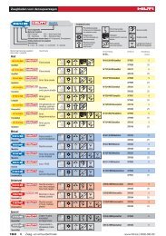
Anchor type<br />
Cracked concrete<br />
<strong>Mechanical</strong> anchor <strong>systems</strong><br />
Heavy duty anchors<br />
HDA-T/ -TR/TF/-P/-PR/-PF<br />
undercut anchor<br />
HSL-3 heavy duty anchor<br />
Medium and light duty<br />
anchors<br />
HSC-A(R) /-I(R) safety anchor<br />
HST/-R/-HCR stud anchor<br />
HSA/-R/-F stud anchor<br />
HSV stud anchor<br />
HLC sleeve anchor<br />
HAM hard sleeve anchor<br />
Uncracked concrete<br />
● ●<br />
● ●<br />
● ●<br />
● ●<br />
●<br />
●<br />
●<br />
●<br />
Base material Approvals<br />
Lightweight concrete<br />
Aerated concrete<br />
Solid brick masonry<br />
Hollow brick masonry<br />
Pre-stressed concrete hollow deck<br />
European Technical Approval<br />
Seismic approval<br />
Fatigue approval or test report<br />
Shock approval<br />
Fire tested<br />
Application<br />
● ● ● ● ● Anchor fastening for high<br />
loads e.g. in steel<br />
construction and plant<br />
construction<br />
● ● ● ● ● Fastening heavy loads e.g.<br />
from columns, high racks,<br />
machines<br />
● ● ● Safety relevant fastening at<br />
facades and ceilings where<br />
short embedment depth is<br />
required<br />
● ● ● ● Fastening through in place<br />
parts e.g. angles, tracks,<br />
channels, wooden beams,<br />
etc.<br />
● ● Fastening through in place<br />
parts like wooden beams,<br />
metal sections, columns,<br />
brackets, etc.<br />
Fastening through in place<br />
parts<br />
● ● Temporary fastenings in<br />
concrete (e.g. formwork),<br />
fastening in base material of<br />
low density<br />
● Secure fastenings in various<br />
base materials<br />
● = very suitable ○ = may be suitable per application ● = technical report 1) redundant fastening<br />
06 / 2011
Advantages<br />
� Automatic undercutting<br />
� High load capacity<br />
� Approved for all dynamic loads<br />
� Integrated plastic section to<br />
telescope and pull down tightly<br />
� The bolt can be retorqued<br />
� Automatic undercutting<br />
� Small edge distances and<br />
spacings<br />
� Small setting depth<br />
� Quick and simple setting<br />
operation<br />
� Setting mark<br />
� Safety wedge for certain follow<br />
06 / 2011<br />
up expansion<br />
� Two setting depths<br />
� Setting mark<br />
� Extremely ductile steel for high<br />
bending capacity<br />
� Quick and simple setting<br />
operation<br />
� Short setting and removing<br />
operation<br />
� Good loads in green concrete<br />
� Bridging of gaps<br />
� Wings to prevent spinning in the<br />
bore hole<br />
� Plastic cap in cone to prevent<br />
dust entrance<br />
Drill bit<br />
diameter resp.<br />
anchor size<br />
Drill bit dia.:<br />
20 – 37 mm<br />
Anchor size:<br />
M10 – M20<br />
Drill bit dia.:<br />
12 – 32 mm<br />
Anchor size:<br />
M8 – M24<br />
Drill bit dia.:<br />
14 – 20 mm<br />
Anchor size:<br />
M6 – M12<br />
Drill bit dia.:<br />
8 – 24 mm<br />
Anchor size:<br />
M8 – M24<br />
Drill bit dia.:<br />
6 – 20 mm<br />
Anchor size:<br />
M8 – M24<br />
Drill bit dia.:<br />
8 – 16 mm<br />
Anchor size:<br />
M8 – M16<br />
Drill bit dia.:<br />
6,5 – 20 mm<br />
Anchor size:<br />
M5 – M16<br />
Drill bit dia.:<br />
12 – 20 mm<br />
Thread:<br />
M6 – M12<br />
Steel, galvanised<br />
Steel, sheradised, hot dipped galv.<br />
● ●<br />
●<br />
●<br />
●<br />
● ●<br />
●<br />
●<br />
●<br />
Specification Setting<br />
Stainless steel A2 (1.4303)<br />
Stainless steel A4 (1.4401)<br />
HCR steel (1.4529)<br />
External thread<br />
Internal thread<br />
Anchor selector<br />
Pre-setting<br />
Through-fastening<br />
Page<br />
● ● ● ● 68<br />
● ● 86<br />
● ● ● ● 98<br />
● ● ● ● ● 122<br />
● ● ● ● 134<br />
● ● ● 146<br />
● ● ● 150<br />
● ● 156<br />
9
Anchor selector<br />
Anchor type<br />
Medium and light duty<br />
anchors<br />
HUS-HR screw anchor<br />
HUS-H screw anchor<br />
HUS-P 6, HUS-I 6 screw anchor<br />
HUS 6 screw anchor<br />
HKD push-in anchor<br />
HKV push-in anchor<br />
HUD-1 universal anchor<br />
HUD-L universal anchor<br />
HLD light duty anchor<br />
10<br />
Cracked concrete<br />
Uncracked concrete<br />
● ●<br />
Base material Approval<br />
Lightweight concrete<br />
Aerated concrete<br />
Solid brick masonry<br />
● ● ● ●<br />
●<br />
1)<br />
●<br />
1)<br />
●<br />
1)<br />
Hollow brick masonry<br />
Pre-stressed concrete hollow deck<br />
European Technical Approval<br />
Seismic approval<br />
Fatigue approval or test report<br />
Shock approval<br />
Fire tested<br />
Application<br />
● ● ● Fastening channels,<br />
brackets, racks, seating<br />
● ● ● Fastening channels,<br />
brackets, racks, seating<br />
● ● ● ● Fastening channels,<br />
brackets, racks, seating<br />
● ● ● ● ●<br />
●<br />
●<br />
● ● ● ● ● ●<br />
● ● ● ● ● ●<br />
● ● ○<br />
● ● Fastening light channels,<br />
brackets, interior panelling<br />
or cladding<br />
● ● Fastening with threaded<br />
rods for pipe suspensions,<br />
air ducts, suspended<br />
ceilings<br />
Fastening with threaded<br />
rods for pipe suspensions,<br />
air ducts, suspended<br />
ceilings<br />
Various applications<br />
Various applications<br />
Fastenings to weak material<br />
with cavities<br />
● = very suitable ○ = may be suitable per application ● = technical report 1) redundant fastening<br />
06 / 2011
Advantages<br />
� Screw driven straight into base<br />
material<br />
� Forged on washer<br />
� Matched system of screw<br />
06 / 2011<br />
anchor and screw driver<br />
� Screw driven straight into base<br />
material<br />
� Forged on washer<br />
� Matched system of screw<br />
anchor and screw driver<br />
� Screw driven straight into base<br />
material<br />
� Forged on washer<br />
� Matched system of screw<br />
anchor and screw driver<br />
� Screw driven straight into base<br />
material<br />
� Small drill bit diameter<br />
� Matched system of screw<br />
anchor and screw driver<br />
� Visual verification of full<br />
expansion<br />
� Small setting depth<br />
� Visual verification of full<br />
expansion<br />
� Small setting depth<br />
� Fast setting<br />
� Flexibility of screw length<br />
� An anchor for every base<br />
material<br />
� Fast setting<br />
� Flexibility of screw length<br />
� An anchor for every base<br />
material<br />
� Flexibility of screw length<br />
� Resilient toggling action to suit<br />
every base material<br />
Drill bit<br />
diameter resp.<br />
anchor size<br />
Drill bit dia.:<br />
6 – 14 mm<br />
Drill bit dia.:<br />
8 – 14 mm<br />
Drill bit dia.:<br />
6 mm<br />
Drill bit dia.:<br />
6 mm<br />
Drill bit dia.:<br />
8 – 25 mm<br />
Anchor size:<br />
M6 – M20<br />
Drill bit dia.:<br />
8 – 20 mm<br />
Anchor size:<br />
M6 – M16<br />
Drill bit dia.:<br />
5 – 14 mm<br />
Drill bit dia.:<br />
6 – 10 mm<br />
Drill bit dia.:<br />
10 mm<br />
Steel, galvanised<br />
●<br />
●<br />
●<br />
●<br />
●<br />
Steel, sheradised, hot dipped galv.<br />
Specification Setting<br />
Stainless steel A2 (1.4303)<br />
Stainless steel A4 (1.4401)<br />
●<br />
HCR steel (1.4529)<br />
External thread<br />
Internal thread<br />
Anchor selector<br />
Pre-setting<br />
Through-fastening<br />
Page<br />
● 158<br />
● 178<br />
● ● 196<br />
● ● 210<br />
● ● ● 216<br />
● ● 240<br />
● ● 244<br />
● ● 250<br />
● 254<br />
11
Anchor selector<br />
Anchor type<br />
12<br />
Cracked concrete<br />
Uncracked concrete<br />
Base material Approvals<br />
Lightweight concrete<br />
Aerated concrete<br />
Solid brick masonry<br />
Medium and light duty<br />
anchors<br />
HRD-U/-S frame anchor ● ● ● ● ●<br />
HRD frame anchor<br />
HPS-1 impact anchor<br />
HHD-S cavity anchor<br />
HCA coil anchor<br />
HSP/HFPdrywall plug<br />
HA8 ring/ hook anchor<br />
DBZ wedge anchor<br />
HT metal frame anchor<br />
HK ceiling anchor<br />
HPD aerated concrete anchor<br />
●<br />
1)<br />
●<br />
1)<br />
●<br />
1)<br />
●<br />
1)<br />
Hollow brick masonry<br />
● ● ●<br />
● ○ ● ● ●<br />
●<br />
●<br />
●<br />
●<br />
● ● ● ● ●<br />
●<br />
●<br />
Pre-stressed concrete hollow deck<br />
European Technical Approval<br />
Seismic approval<br />
Fatigue approval or test report<br />
Shock approval<br />
Fire tested<br />
Application<br />
● ● Securing support frames,<br />
timber frames, fascade<br />
panels, curtain walling<br />
● ● On most hollow and solid<br />
base material<br />
Fastening wood battens,<br />
components for electrical<br />
and plumbing installations<br />
Fastening battens, channels<br />
panels<br />
Temporary external<br />
fastenings<br />
Fastenings in dry walls<br />
● ● For suspended ceilings and<br />
other items from concrete<br />
ceilings<br />
● ● Suspension from concrete<br />
ceilings e.g. using steel<br />
straps, punched band,<br />
Nonius system hanger<br />
Fastening door and window<br />
frames<br />
● ● Fastening of suspended<br />
ceilings, cable trays, pipes<br />
● Various fastenings<br />
● = very suitable ○ = may be suitable per application ● = technical report 1) redundant fastening<br />
06 / 2011
Advantages<br />
� Preassembled with screw<br />
� Screw of steel 5.8 grade or<br />
stainless steel A4 (1.4401)<br />
� impact and temperature<br />
resistant<br />
� high quality plastic<br />
� impact and temperature<br />
resistant<br />
� high quality plastic<br />
� Controlled setting<br />
� Deliverable with or without<br />
prefitted screw<br />
� Re-usable<br />
� Removable<br />
� Self-drilling tip<br />
� One bit for anchor and screw<br />
� Removable<br />
� Quick and easy setting<br />
� Automatic follow up expansion<br />
� Small drill bit diameter<br />
� Quick setting by impact<br />
extension<br />
� Automatic follow up expansion<br />
� No risk of distortion or forces of<br />
constraint<br />
� Expansion cone can not be lost<br />
� Small bore hole<br />
� Quick and easy setting<br />
� Approved (DIBt)<br />
� Fire resistance<br />
� Immediately loadable<br />
06 / 2011<br />
Drill bit<br />
diameter resp.<br />
anchor size<br />
Drill bit dia.:<br />
10 and 14 mm<br />
Drill bit dia.:<br />
8 – 10 mm<br />
Steel, galvanised<br />
Steel, sheradised, hot dipped galv.<br />
Specification Setting<br />
Stainless steel A2 (1.4303)<br />
Stainless steel A4 (1.4401)<br />
● ●<br />
● ●<br />
4 – 8 mm ● ●<br />
Drill bit dia.:<br />
8 – 12 mm<br />
Drill bit dia.:<br />
16 mm<br />
-<br />
Drill bit dia.:<br />
8 mm<br />
Drill bit dia.:<br />
6 mm<br />
Drill bit dia.:<br />
8 – 10 mm<br />
Drill bit dia.:<br />
6 mm<br />
M6<br />
Without<br />
predrilling<br />
Thread:<br />
M6 – M10<br />
●<br />
●<br />
●<br />
●<br />
●<br />
●<br />
HCR steel (1.4529)<br />
External thread<br />
Internal thread<br />
Anchor selector<br />
Pre-setting<br />
Through-fastening<br />
Page<br />
● 258<br />
● 264<br />
● ● 280<br />
● 284<br />
286<br />
● 288<br />
● 290<br />
● 294<br />
● 298<br />
● ● 302<br />
● ● 308<br />
13
Anchor selector<br />
Anchor type<br />
Medium and light duty<br />
anchors<br />
HKH hollow deck anchor<br />
HTB<br />
Insulation fasteners<br />
IDP insulation<br />
fastener<br />
IZ expandable insulation fastener<br />
IDMS / IDMR insulation fastener<br />
14<br />
Cracked concrete<br />
Uncracked concrete<br />
Base material Approvals<br />
Lightweight concrete<br />
Aerated concrete<br />
Solid brick masonry<br />
Hollow brick masonry<br />
● ● ● ●<br />
● ● ● ●<br />
● ● ● ●<br />
Pre-stressed concrete hollow deck<br />
European Technical Approval<br />
Seismic approval<br />
Fatigue approval or test report<br />
Shock approval<br />
Fire tested<br />
Application<br />
● ● ● Suspension from prestressed<br />
concrete hollow<br />
decks<br />
● ● Ingenious and strong for<br />
hollow base materials<br />
Fastening of hard, self<br />
supporting insulating<br />
materials<br />
Fastening of soft and hard,<br />
self supporting insulating<br />
materials<br />
Fastening of soft and hard,<br />
self supporting insulating<br />
materials and non self<br />
supporting insulation<br />
materials<br />
● = very suitable ○ = may be suitable per application ● = technical report 1) redundant fastening<br />
06 / 2011
Advantages<br />
� Approval for single point<br />
fastenings<br />
� Approved for sprinkler <strong>systems</strong><br />
� Load carried by strong metal<br />
channel and screw<br />
� Convincing simplicity when<br />
setting<br />
� One piece element<br />
� Corrosion resistant<br />
� No heat bridge<br />
� Corrosion resistant<br />
� No heat bridge<br />
� Reliable bonding of plaster<br />
� One piece element<br />
� Corrosion resistant<br />
� Fire resistant<br />
06 / 2011<br />
Drill bit<br />
diameter resp.<br />
anchor size<br />
Drill bit dia.:<br />
10 – 14 mm<br />
Thread:<br />
M6 – M10<br />
Drill bit dia.:<br />
13 – 14 mm<br />
Drill bit dia.:<br />
8 mm insulating<br />
material<br />
thickness<br />
10 – 150mm<br />
Drill bit dia.:<br />
8 mm insulating<br />
material<br />
thickness<br />
up to 180mm<br />
Drill bit dia.:<br />
8 mm insulating<br />
material<br />
thickness<br />
up to 150mm<br />
Steel, galvanised<br />
●<br />
Steel, sheradised, hot dipped galv.<br />
● ●<br />
Specification Setting<br />
Stainless steel A2 (1.4303)<br />
Stainless steel A4 (1.4401)<br />
HCR steel (1.4529)<br />
External thread<br />
Internal thread<br />
Anchor selector<br />
Pre-setting<br />
Through-fastening<br />
Page<br />
● ● ● 314<br />
● 318<br />
● 322<br />
● 326<br />
● 330<br />
15
Anchor selector<br />
Anchor type<br />
Adhesive anchor <strong>systems</strong><br />
Foil capsule <strong>systems</strong><br />
HVZ<br />
adhesive<br />
anchor<br />
HVU<br />
adhesive<br />
anchor<br />
Injection mortar <strong>systems</strong><br />
HIT-RE<br />
500–SD<br />
HIT-RE<br />
500<br />
16<br />
Cracked concrete<br />
Uncracked concrete<br />
● ●<br />
●<br />
● ●<br />
●<br />
Base material Approvals<br />
Lightweight concrete<br />
Aerated concrete<br />
Solid brick masonry<br />
Hollow brick masonry<br />
Pre-stressed concrete hollow deck<br />
European Technical Approval<br />
Seismic approval<br />
Fatigue approval or test report<br />
Shock approval<br />
Fire tested<br />
Application<br />
● ● ● Heavy-duty fastenings with<br />
small spacing and edge<br />
distances<br />
● ● Heavy duty fastenings with<br />
small spacing and edge<br />
distances<br />
● ● ● ● Adhesive anchor in cracked<br />
concrete<br />
● ● Adhesive anchor<br />
● = very suitable ○ = may be suitable per application ● = technical report 1) redundant fastening<br />
06 / 2011
Advantages<br />
� No expansion pressure<br />
� Small edge distances and<br />
spacing<br />
� A strong and flexible foil capsule<br />
� No expansion pressure<br />
� Small edge distances and<br />
spacing<br />
� A strong and flexible foil capsule<br />
� Flexibility in terms of working<br />
time<br />
� No expansion pressure<br />
� Flexibility in terms of drill bit<br />
diameter and annular gap<br />
� Flexibility in terms of working<br />
time<br />
06 / 2011<br />
Drill bit<br />
diameter resp.<br />
anchor size<br />
Steel, galvanised<br />
M10 – M20 ●<br />
HAS M8 – M39<br />
HIS-M8 - M20<br />
Rebar dia.<br />
8 – 40 mm<br />
HAS M8 – M30<br />
HIS-M8 - M20<br />
Rebar dia.<br />
8 – 32 mm<br />
HAS M8 – M39<br />
HIS-M8 - M20<br />
Rebar dia.<br />
8 – 40 mm<br />
●<br />
●<br />
●<br />
Steel, sheradised, hot dipped galv.<br />
Specification Setting<br />
Stainless steel A2 (1.4303)<br />
Stainless steel A4 (1.4401)<br />
HCR steel (1.4529)<br />
External thread<br />
Internal thread<br />
Anchor selector<br />
Pre-setting<br />
Through-fastening<br />
Page<br />
● ● ● ● 336<br />
● ● ● ● ● 350<br />
● ● ● ● ● 374<br />
● ● ● ● ● 430<br />
17
Anchor selector<br />
Anchor type<br />
Injection mortar <strong>systems</strong><br />
HIT-HY<br />
150 MAX<br />
HIT-HY<br />
150<br />
HIT ICE<br />
HIT-HY<br />
70<br />
18<br />
Cracked concrete<br />
Uncracked concrete<br />
Base material Approvals<br />
Lightweight concrete<br />
● ● ●<br />
● ●<br />
●<br />
●<br />
Aerated concrete<br />
Solid brick masonry<br />
Hollow brick masonry<br />
Pre-stressed concrete hollow deck<br />
European Technical Approval<br />
Seismic approval<br />
Fatigue approval or test report<br />
Shock approval<br />
Fire tested<br />
Application<br />
● Adhesive anchor in cracked<br />
concrete<br />
● ● Adhesive anchor<br />
Adhesive anchor for low<br />
installation temperatures<br />
● ● ● Universal mortar for solid<br />
and hollow brick<br />
● = very suitable ○ = may be suitable per application ● = technical report 1) redundant fastening<br />
06 / 2011
Advantages<br />
� No expansion pressure<br />
� No styrene content<br />
� No plasticizer content<br />
� Environmental protection due to<br />
the minimized packaging<br />
� No expansion pressure<br />
� No styrene content<br />
� No plasticizer content<br />
� Environmental protection due to<br />
the minimized packaging<br />
06 / 2011<br />
Drill bit<br />
diameter resp.<br />
anchor size<br />
HAS M8 – M30<br />
HIS-M8 - M20<br />
Rebar dia.<br />
8 – 25 mm<br />
HAS M8 – M30<br />
HIS-M8 - M20<br />
Rebar dia.<br />
8 – 25 mm<br />
� No expansion pressure HAS M8 – M24<br />
HIS-M8 - M20<br />
Rebar dia.<br />
8 – 25 mm<br />
� No expansion pressure<br />
� mortar filling control<br />
with HIT-SC sleeves<br />
Drill bit dia.:<br />
10 – 22 mm<br />
Thread:<br />
M6 – M12<br />
Steel, galvanised<br />
●<br />
●<br />
●<br />
●<br />
Steel, sheradised, hot dipped galv.<br />
Specification Setting<br />
Stainless steel A2 (1.4303)<br />
Stainless steel A4 (1.4401)<br />
HCR steel (1.4529)<br />
External thread<br />
Internal thread<br />
Anchor selector<br />
Pre-setting<br />
Through-fastening<br />
Page<br />
● ● ● ● ● 486<br />
● ● ● ● ● 552<br />
● ● ● ● ● 600<br />
● ● ● ● 648<br />
19
Legal environment<br />
Legal environment<br />
Technical data<br />
The technical data presented in this Anchor Fastening Technology Manual are all based on<br />
numerous tests and evaluation according to the state-of-the art. <strong>Hilti</strong> anchors are tested in our<br />
test labs in Kaufering (Germany), Schaan (Principality of Liechtenstein) or Tulsa (USA) and<br />
evaluated by our experienced engineers and/or tested and evaluated by independent testing<br />
institutes in Europe and the USA. Where national or international regulations do not cover all<br />
possible types of applications, additional <strong>Hilti</strong> data help to find customised solutions.<br />
In addition to the standard tests for admissible service conditions and suitability tests, for safety<br />
relevant applications fire resistance, shock, seismic and fatigue tests are performed.<br />
European Technical Approval Guidelines<br />
Approval based data given in this manual are either according to European Technical Approval<br />
Guidelines (ETAG) or have been evaluated according to this guidelines and/or national<br />
regulations.<br />
The European Technical Approval Guideline ETAG 001 „METAL ANCHORS FOR USE IN<br />
CONCRETE“ sets out the basis for assessing anchors to be used in concrete (cracked and noncracked).<br />
It consists of:<br />
� Part 1 Anchors in general<br />
� Part 2 Torque-controlled expansion anchors<br />
� Part 3 Undercut anchors<br />
� Part 4 Deformation-controlled expansion anchors<br />
� Part 5 Bonded anchors<br />
� Part 6 Anchors for multiple use for non-structural applications<br />
� Annex A Details of test<br />
� Annex B Tests for admissible service conditions – detailed information<br />
� Annex C Design methods for anchorages<br />
For special anchors for use in concrete, additional Technical Reports (TR) related to ETAG 001<br />
set out additional requirements:<br />
� TR 018 Assessment of torque-controlled bonded anchors<br />
� TR 020 Evaluation of Anchorages in Concrete concerning Resistance to Fire<br />
� TR 029 Design of Bonded Anchors<br />
The European Technical Approval Guideline ETAG 020 „ PLASTIC ANCHORS FOR<br />
MULTIPLE USE IN CONCRETE AND MASONRY FOR NON-STRUCTURAL APPLICATIONS“<br />
sets out the basis for assessing plastic anchors to be used in concrete or masonry for<br />
redundant fastenings (multiple use). It consists of:<br />
� Part 1 General<br />
� Part 2 Plastic anchors for use in normal weight concrete<br />
� Part 3 Plastic anchors for use in solid masonry materials<br />
� Part 4 Plastic anchors for use in hollow or perforated masonry<br />
� Part 5 Plastic anchors for use in autoclaved aerated concrete (AAC)<br />
� Annex A Details of tests<br />
� Annex B Recommendations for tests to be carried out on construction works<br />
� Annex C Design methods for anchorages<br />
20<br />
06 / 2011
06 / 2011<br />
Legal environment<br />
The European Technical Approval Guidelines including related Technical Reports set out the<br />
requirements for anchors and the acceptance criteria they shall meet.<br />
The general assessment approach adopted in the Guideline is based on combining relevant<br />
existing knowledge and experience of anchor behaviour with testing. Using this approach,<br />
testing is needed to assess the suitability of anchors.<br />
The requirements in European Technical Approval Guidelines are set out in terms of objectives<br />
and of relevant actions to be taken into account. ETAGs specify values and characteristics, the<br />
conformity with which gives the presumption that the requirements set out are satisfied,<br />
whenever the state of art permits to do so. The Guidelines may indicate alternate possibilities<br />
for the demonstration of the satisfaction of the requirements.<br />
Post-installed rebar connections<br />
The basis for the assessment of post-installed rebar connections is set out in the Technical<br />
Report<br />
� TR 023 Assessment of post-installed rebar connections<br />
The Technical Report TR 023 covers post-installed rebar connections designed in accordance<br />
with EN 1992 - 1-1: 2004 (EC2) only. ETAG 001 (Part 1 and Part 5) is the general basic of this<br />
application. The Technical Report TR 023 deals with the preconditions, assumptions and the<br />
required tests and assessments for postinstalled rebars.<br />
System of attestation of conformity<br />
For anchors having an approval, the conformity of the product shall be certified by an approved<br />
certification body (notified body) on the basis of tasks for the manufacturer and tasks for the<br />
approved body.<br />
Tasks for the manufacturer are:<br />
� Factory production control (permanent internal control of production and documentation<br />
according to a prescribed test plan)<br />
� involve a body which is approved for the tasks<br />
Tasks for the approved body are:<br />
� initial type-testing of the product<br />
� initial inspection of factory and of factory production control<br />
� continuous surveillance, assessment and approval of factory production control<br />
21
Approvals<br />
Approvals<br />
European Technical Approvals: Europe<br />
Anchor type Description Authority /<br />
Laboratory<br />
HDA / HDA-R Self-undercutting anchor made of<br />
galvanised or stainless steel<br />
(Valid until: 25.03.2013)<br />
HSL-3 Torque controlled expansion anchor<br />
of galvanised steel<br />
(Valid until: 10.01.2013)<br />
HSC / HSC-R Self-undercutting anchor made of<br />
galvanised or stainless steel<br />
(Valid until: 20.09.2012)<br />
HST / HST-R /<br />
HST-HCR<br />
22<br />
Expansion stud anchor made of<br />
galvanised, stainless or highly<br />
corrosion resistant steel<br />
(Valid until: 19.02.2013)<br />
HSA / HSA-R Expansion stud anchor made of<br />
galvanised or stainless steel<br />
(Valid until: 13.03.2013)<br />
HUS-HR<br />
6/8/10/14<br />
HUS-H 6/8/10<br />
HUS-A/-I-P 6<br />
Screw anchor made of stainless<br />
steel or carbon steel, deltatone<br />
coated,<br />
(Valid until: 12.12.2013)<br />
HUS 6 Screw anchor made of carbon steel,<br />
deltatone coated<br />
(Valid until: 23.04.2015)<br />
HKD / HKD-R Deformation controlled expansion<br />
anchor made of galvanised or<br />
stainless steel<br />
(Vailid until: 14.03.2016)<br />
HKD / HKD-R Deformation controlled expansion<br />
anchor made of galvanised or<br />
stainless steel<br />
(Vailid until: 12.10.2012)<br />
HRD Frame anchor made of polyamide,<br />
screw made of galvanised or<br />
stainless steel<br />
(Valid until: 17.09.2012)<br />
DBZ Wedge anchor made of galvanised<br />
steel<br />
(Valid until: 13.09.2011)<br />
HK Ceiling anchor made of galvanised<br />
steel (Valid until: 23.04.2014)<br />
HVZ / HVZ-R /<br />
HVZ-HCR<br />
HVU with<br />
HAS / HAS-R /<br />
HAS-HCR<br />
HIS-N / HIS-RN<br />
Adhesive anchor, rod made of<br />
galvanised, stainless or highly<br />
corrosion resistant steel<br />
(Valid until: 01.10.2013)<br />
Adhesive anchor, rod made<br />
galvanized steel, stainless steel or<br />
highly corrosion resistant steel<br />
(Valid until 20.01.2016)<br />
No. /<br />
Languages<br />
Date of issue g e f<br />
CSTB, Paris ETA-99/0009<br />
17.12.2010<br />
� � �<br />
CSTB, Paris ETA-02/0042<br />
10.01.2008<br />
CSTB, Paris ETA-02/0027<br />
20.09.2007<br />
DIBt, Berlin ETA-98/0001<br />
17.06.2011<br />
CSTB, Paris ETA-99/0001<br />
13.03.2008<br />
DIBt, Berlin ETA-08/307<br />
21.01.2011<br />
DIBt, Berlin ETA-10/0005<br />
12.05.2011<br />
DIBt, Berlin ETA-06/0047<br />
14.03.2011<br />
DIBt, Berlin ETA-02/0032<br />
22.04.2010<br />
DIBt, Berlin ETA-07/0219<br />
01.02.2011<br />
DIBt, Berlin ETA-06/0179<br />
13.09.2006<br />
DIBt, Berlin ETA-04/0043<br />
30.06.2010<br />
DIBt, Berlin ETA-03/0032<br />
29.09.2008<br />
DIBt Berlin ETA-05/0255<br />
20.01.2016<br />
� � �<br />
� � �<br />
� � �<br />
� � �<br />
� � �<br />
� � �<br />
� �<br />
� � �<br />
� �<br />
� � �<br />
� �<br />
� � �<br />
� � �<br />
06 / 2011
Anchor type Description Authority /<br />
Laboratory<br />
HIT-RE 500-SD<br />
with HIT-V/<br />
HIS-N/<br />
HIT-V-R/ HIS-<br />
RN/ HIT-V-HCR/<br />
rebar BSt 500S<br />
06 / 2011<br />
Injection adhesive anchor, rod made<br />
of galvanised, stainless or highly<br />
corrosion resistant steel<br />
(Valid until 08.11.2012)<br />
Approvals<br />
No. /<br />
Languages<br />
Date of issue g e f<br />
DIBt Berlin ETA-07/0260<br />
12.01.2009<br />
� � �<br />
HIT-RE 500-SD Injection adhesive for reinforcing bar DIBt Berlin ETA-09/0295<br />
connections (Valid until: 08.05.2013)<br />
14.09.2009<br />
HIT-RE 500 with Injection adhesive anchor, rod made DIBt Berlin ETA-04/0027<br />
HIT-V/ HAS-(E)/ of galvanised, stainless or highly<br />
20.05.2009<br />
HIS-N/<br />
corrosion resistant steel<br />
HIT-V-R/ HAS-<br />
(E)R/ HIS-RN/<br />
HIT-V-HCR/<br />
HAS-(E)HCR<br />
(Valid until 28.05.2014)<br />
HIT-RE 500 Injection adhesive for reinforcing bar DIBt Berlin ETA-08/0105<br />
connections (Valid until: 08.05.2013)<br />
30.07.2008<br />
HIT-HY 150 MAX Injection adhesive anchor, rod made DIBt Berlin ETA-04/0084<br />
with HIT-TZ / of galvanised or stainless steel<br />
09.12.2009<br />
HIT-RTZ (Valid until 23.09.2014)<br />
HIT-HY 150 MAX Injection adhesive anchor, rod made CSTB, Paris ETA-08-352<br />
with HIT-V/ HAS- of galvanised, stainless or highly<br />
01.04.2010<br />
(E)/ HIS-N/ corrosion resistant steel<br />
HIT-V-R/ HAS-<br />
(E)R/ HIS-RN/<br />
HIT-V-HCR/<br />
HAS-(E)HCR<br />
(Valid until 18.12.2013)<br />
HIT-HY 150 MAX Injection adhesive for reinforcing bar CSTB, Paris ETA-08/0202<br />
connections (Valid until: 24.07.2013)<br />
24.07.2008<br />
HIT-HY 150 with Injection adhesive anchor, rod made DIBt Berlin ETA-05/0051<br />
HIT-V/ HAS-(E)/ of galvanised, stainless or highly<br />
17.03.2011<br />
HIS-N/<br />
corrosion resistant steel<br />
HIT-V-R/ HAS-<br />
(E)R/ HIS-RN/<br />
HIT-V-HCR/<br />
HAS-(E)HCR<br />
(Valid until 17.03.2012)<br />
� � �<br />
� � �<br />
� � �<br />
� � �<br />
� � �<br />
� � �<br />
� �<br />
23
Approvals<br />
Additional National European Approvals<br />
France<br />
Anchor type Description Authority / No. /<br />
Languages<br />
Laboratory Date of issue g e f<br />
HIT-HY 70 Injection adhesive, rod made of<br />
galvanised steel<br />
(Valid until: 30.06.2012)<br />
SOCOTEC, Paris YX 0047 06.2009 �<br />
Germany<br />
Anchor type Description Authority /<br />
Laboratory<br />
HDA Self-undercutting anchor made of<br />
galvanised steel for unusual actions<br />
(loads) – for use in Nuclear power<br />
plants) (Valid until: 31.05.2013)<br />
HDA- Dynamic Self-undercutting anchor made of<br />
galvanised steel for dynamic loads<br />
(Valid until: 30.09.2011)<br />
HUS,-H/-A 6 Screw anchor made of galvanised<br />
steel (Valid until: 31.07.2012)<br />
HRD Frame anchor made of polyamide,<br />
screw made of galvanised or<br />
stainless steel<br />
(Valid until: 31.10.2012)<br />
HPD Aerated concrete anchor made of<br />
galvanised steel<br />
(Valid until: 31.05.2016)<br />
HKH Hollow deck anchor made of<br />
galvanised steel<br />
(Valid until: 31.10.2011)<br />
HVZ-Dynamic Adhesive anchor, rod made of<br />
galvanised steel<br />
(Valid until:31.10.2011)<br />
HIT-RE 500 Injection adhesive for reinforcing bar<br />
connections (Valid until: 31.03.2014)<br />
HIT-HY 150 MAX Injection adhesive for reinforcing bar<br />
connections (Valid until: 30.11.2014)<br />
HIT-HY 70 Injection adhesive anchor for<br />
masonry, rod made of galvanised,<br />
stainless or highly corrosion<br />
resistant steel<br />
(Valid until: 30.11.2011)<br />
24<br />
No. /<br />
Date of issue<br />
DIBt, Berlin Z-21.1-1696<br />
16.02.2011<br />
DIBt, Berlin Z-21.1-1693<br />
07.01.2010<br />
DIBt, Berlin Z-21.1-1710<br />
20.05.2009<br />
DIBt, Berlin Z-21.2-599<br />
25.10.2007<br />
DIBt, Berlin Z-21.1-1729<br />
31.05.2011<br />
DIBt, Berlin Z-21.1-1722<br />
21.10.2008<br />
DIBt, Berlin Z-21.3-1692<br />
18.10.2006<br />
DIBt, Berlin Z-21.8-1790<br />
16.03.2009<br />
DIBt, Berlin Z-21.8-1882<br />
16.12.2009<br />
DIBt, Berlin Z-21.3-1830<br />
20.01.2009<br />
Languages<br />
g<br />
�<br />
e f<br />
�<br />
�<br />
�<br />
�<br />
�<br />
�<br />
�<br />
�<br />
�<br />
06 / 2011
Switzerland<br />
Anchor type Description Authority /<br />
Laboratory<br />
HDA-P<br />
HDA -PF<br />
HDA -PR<br />
HDA-T<br />
HDA -TF<br />
HDA -TR<br />
HSL-3<br />
HSL-3-G<br />
HSL-3-B<br />
HSL-3-SK<br />
HSL-3-SH<br />
HSC-I(R)<br />
HSC-A(R)<br />
06 / 2011<br />
Undercut anchor for shockproof<br />
fastenings in civil defence<br />
installations<br />
Heavy duty anchor for shockproof<br />
fastenings in civil defence<br />
installations<br />
Safety anchor for shockproof<br />
fastenings in civil defence<br />
installations<br />
HST / HST-R Stud anchor for shockproof<br />
fastenings in civil defence<br />
installations<br />
HVZ / HVZ-R Adhesive anchor for shockproof<br />
fastenings in civil defence<br />
installations<br />
HIT-RE 500-SD Adhesive anchor for shockproof<br />
fastenings in civil defence<br />
installations<br />
USA<br />
Federal Office for<br />
Civil Protection,<br />
Bern<br />
Federal Office for<br />
Civil Protection,<br />
Bern<br />
Federal Office for<br />
Civil Protection,<br />
Bern<br />
Federal Office for<br />
Civil Protection,<br />
Bern<br />
Federal Office for<br />
Civil Protection,<br />
Bern<br />
Federal Office for<br />
Civil Protection,<br />
Bern<br />
Anchor type Description Authority /<br />
Laboratory<br />
HDA-P<br />
HDA -PR<br />
HDA-T<br />
HDA -TR<br />
HSL-3<br />
HSL-3-G<br />
HSL-3-B<br />
HSL-3-SK<br />
HSL-3-SH<br />
Evaluation report of <strong>Hilti</strong> HDA Metric<br />
Undercut Anchor<br />
Evaluation report of <strong>Hilti</strong> HSL-3<br />
Heavy Duty Anchor<br />
HIT RE 500-SD Evaluation report of <strong>Hilti</strong> HIT RE<br />
500-SD Adhesive Anchoring System<br />
HIT-HY 150 MAX Evaluation report of <strong>Hilti</strong> HIT-HY 150<br />
MAX adhesive anchor<br />
Approvals<br />
No. /<br />
Languages<br />
Date of issue g e f<br />
BZS D 09-601<br />
21.10.2009<br />
� �<br />
BZS D 08-601<br />
30.06.2008<br />
BZS D 06-601<br />
10.07.2006<br />
BZS D 08-602<br />
15.12.2008<br />
BZS D 09-602<br />
21.10.2009<br />
BZS D 08-604<br />
21.10.2009<br />
No. /<br />
Date of issue<br />
ICC-ES ESR-1546<br />
01.03.2008<br />
ICC-ES ESR-1545<br />
01.03.2010<br />
ICC-ES ESR-2322<br />
01.04.2010<br />
ICC-ES ESR-2262<br />
01.08.2010<br />
� �<br />
� �<br />
� �<br />
� �<br />
� �<br />
Languages<br />
g e<br />
�<br />
f<br />
�<br />
�<br />
�<br />
25
Base materials<br />
Base material<br />
General<br />
Different <strong>anchoring</strong> conditions The wide variety of building materials used today provide different<br />
<strong>anchoring</strong> conditions for anchors. There is hardly a base material in or to<br />
which a fastening cannot be made with a <strong>Hilti</strong> product. However, the<br />
properties of the base material play a decisive role when selecting a<br />
suitable fastener / anchor and determining the load it can hold.<br />
Concrete<br />
A mixture of cement,<br />
aggregates and water<br />
Cracking from bending<br />
Stress and strain in sections<br />
withconditions I and II<br />
If cracks in the tension zone<br />
exist, suitable anchor <strong>systems</strong><br />
are required<br />
Observe curing of concrete<br />
when using expansion<br />
anchors<br />
26<br />
The main building materials suitable for anchor fastenings have been<br />
described in the following.<br />
Concrete is synthetic stone, consisting of a mixture of cement, aggregates<br />
and water, possibly also additives, which is produced when the cement<br />
paste hardens and cures. Concrete has a relatively high compressive<br />
strength, but only low tensile strength. Steel reinforcing bars are cast in<br />
concrete to take up tensile forces. It is then referred to as reinforced<br />
concrete.<br />
�b, D calculated compressive stress<br />
�b, Z<br />
fct<br />
calculated tensile stress<br />
concrete tensile strength<br />
If the tensile strength of concrete is exceeded, cracks form, which, as a<br />
rule, cannot be seen. Experience has shown that the crack width does not<br />
exceed the figure regarded as admissible, i.e. w � 0.3mm, if the concrete is<br />
under a constant load. If it is subjected predominately to forces of<br />
constraint, individual cracks might be wider if no additional reinforcement is<br />
provided in the concrete to restrict the crack width. If a concrete component<br />
is subjected to a bending load, the cracks have a wedge shape across the<br />
component cross-section and they end close to the neutral axis. It is<br />
recommended that anchors that are suitable in cracked concrete be used in<br />
the tension zone of concrete components. Other types of anchors can be<br />
used if they are set in the compression zone.<br />
Anchors are set in both low-strength and high-strength concrete. Generally,<br />
the range of the cube compressive strength, fck,cube, 150, is between 25 and<br />
60 N/mm². Expansion anchors should not be set in concrete which has not<br />
cured for more than seven days. If anchors are loaded immediately after<br />
they have been set, the loading capacity can be assumed to be only the<br />
actual strength of the concrete at that time. If an anchor is set and the load<br />
applied later, the loading capacity can be assumed to be the concrete<br />
strength determined at the time of applying the load.<br />
06 / 2011
Cutting through reinforcement when drilling anchor holes must be avoided.<br />
If this is not possible, the design engineer responsible must be consulted<br />
first.<br />
Masonry<br />
Masonry is a heterogeneous base material. The hole being drilled for an<br />
anchor can run into mortar joints or cavities. Owing to the relatively low<br />
strength of masonry, the loads taken up locally cannot be particularly high.<br />
A tremendous variety of types and shapes of masonry bricks are on the<br />
market, e.g. clay bricks, sand-lime bricks or concrete bricks, all of different<br />
shapes and either solid or with cavities. <strong>Hilti</strong> offers a range of different<br />
fastening solutions for this variety of masonry base material, e.g. the HPS-<br />
1, HRD, HUD, HIT, etc.<br />
If there are doubts when selecting a fastener / anchor, your local <strong>Hilti</strong> sales<br />
representative will be pleased to provide assistance.<br />
When making a fastening, care must be taken to ensure that a lay of<br />
insulation or plaster is not used as the base material. The specified<br />
anchorage depth (depth of embedment) must be in the actual base<br />
material.<br />
Other base materials<br />
Aerated concrete: This is manufactured from fine-grained sand as the<br />
aggregate, lime and/or cement as the binding agent, water and aluminium<br />
as the gas-forming agent. The density is between 0.4 and 0.8 kg/dm³ and<br />
the compressive strength 2 to 6 N/mm². <strong>Hilti</strong> offers the HGN and HRD-U<br />
anchors for this base material.<br />
Lightweight concrete: This is concrete which has a low density, i.e. ≤ 1800<br />
kg/m³, and a porosity that reduces the strength of the concrete and thus the<br />
loading capacity of an anchor. <strong>Hilti</strong> offers the HRD, HUD, HGN, etc anchor<br />
<strong>systems</strong> for this base material.<br />
Drywall (plasterboard/gypsum) panels: These are mostly building<br />
components without a supporting function, such as wall and ceiling panels,<br />
to which less important, so-called secondary fastenings are made. The <strong>Hilti</strong><br />
anchors suitable for this material are the HTB, HLD and HHD.<br />
In addition to the previously named building materials, a large variety of<br />
others, e.g. natural stone, etc, can be encountered in practice. Furthermore,<br />
special building components are also made from the previously<br />
mentioned materials which, because of manufacturing method and<br />
configuration, result in base materials with peculiarities that must be given<br />
careful attention, e.g. hollow ceiling floor components, etc.<br />
Descriptions and explanations of each of these would go beyond the<br />
bounds of this manual. Generally though, fastenings can be made to these<br />
materials. In some cases, test reports exist for these special materials. It is<br />
also recommended that the design engineer, company carrying out the<br />
work and <strong>Hilti</strong> technical staff hold a discussion in each case.<br />
In some cases, testing on the jobsite should be arranged to verify the<br />
suitability and the loading capacity of the selected anchor.<br />
06 / 2011<br />
Base materials<br />
Avoid cutting reinforcement<br />
Different types and shapes<br />
Plaster coating is not a base<br />
material for fastenings<br />
Aerated concrete<br />
Lightweight concrete<br />
Drywall / gypsum panels<br />
Variety of base materials<br />
Jobsite tests<br />
27
Base materials<br />
Why does an anchor hold in a base material?<br />
Working principles<br />
There are three basic working principles which make an anchor hold in a building material:<br />
Friction<br />
Keying<br />
Bonding<br />
Combination of working<br />
principles<br />
Force-controlled and<br />
displacement-controlled<br />
expansion anchors<br />
Adhesive/resin anchor<br />
28<br />
The tensile load, N, is transferred to<br />
the base material by friction, R. The<br />
expansion force, Fexp, is necessary<br />
for this to take place. It is produced,<br />
for example, by driving in an<br />
expansion plug (HKD).<br />
The tensile load, N, is in equilibrium<br />
with the supporting forces, R, acting<br />
on the base material, such as with<br />
the HDA anchor.<br />
An adhesive bond is produced<br />
between the anchor rod and the<br />
hole wall by a synthetic resin<br />
adhesive, such as with HVU with<br />
HAS anchor rods.<br />
Many anchors obtain their holding power from a combination of the above<br />
mentioned working principles.<br />
For example, an anchor exerts an expansion force against wall of its hole<br />
as a result of the displacement of a cone relative to a sleeve. This permits<br />
the longitudinal force to be transferred to the anchor by friction. At the same<br />
time, this expansion force causes permanent local deformation of the base<br />
material, above all in the case of metal anchors. A keying action results<br />
which enables the longitudinal force in the anchor to be transferred<br />
additionally to the base material<br />
In the case of expansion anchors, a distinction is made between forcecontrolled<br />
and movement-controlled types. The expansion force of forcecontrolled<br />
expansion anchors is dependent on the tensile force in the<br />
anchor (HSL-3 heavy-duty anchor). This tensile force is produced, and thus<br />
controlled, when a tightening torque is applied to expand the anchor.<br />
In the case of movement-controlled types, expansion takes place over a<br />
distance that is predetermined by the geometry of the anchor in the<br />
expanded state. Thus an expansion force is produced (HKD anchor) which<br />
is governed by the modulus of elasticity of the base material.<br />
The synthetic resin of an adhesive anchor infiltrates into the pores of the<br />
base material and, after it has hardened and cured, achieves a local keying<br />
action in addition to the bond.<br />
06 / 2011
Failure modes<br />
Effects of static loading<br />
The failure patterns of anchor fastenings subjected to a continually<br />
increased load can be depicted as follows:<br />
06 / 2011<br />
1. 2.<br />
3. 3a.<br />
4.<br />
The weakest point in an anchor fastening determines the cause of failure.<br />
Modes of failure, 1. break-out, 2. anchor pull-away and, 3., 3a., failure of<br />
anchor parts, occur mostly when single anchors that are a suitable<br />
distance from an edge or the next anchor, are subjected to a pure tensile<br />
load. These causes of failure govern the max. loading capacity of anchors.<br />
On the other hand, a small edge distance causes mode of failure 4. edge<br />
breaking. The ultimate loads are then smaller than those of the previously<br />
mentioned modes of failure. The tensile strength of the fastening base<br />
material is exceeded in the cases of break-out, edge breaking and splitting.<br />
Basically, the same modes of failure take place under a combined load.<br />
The mode of failure 1. break-out, becomes more seldom as the angle<br />
between the direction of the applied load and the anchor axis increases.<br />
Generally, a shear load causes a conchoidal (shell-like) area of spall on<br />
one side of the anchor hole and, subsequently, the anchor parts suffer<br />
bending tension or shear failure. If the distance from an edge is small and<br />
the shear load is towards the free edge of a building component, however,<br />
the edge breaks away.<br />
Failure patterns<br />
Causes of failure<br />
Combined load<br />
Shear load<br />
Base materials<br />
29
Base materials<br />
Influence of cracks<br />
Very narrow cracks are not<br />
defects in a structure<br />
Efficient utilisation of<br />
reinforcement<br />
30<br />
It is not possible for a reinforced concrete structure to be built which does<br />
not have cracks in it under working conditions. Provided that they do not<br />
exceed a certain width, however, it is not at all necessary to regard cracks<br />
as defects in a structure. With this in mind, the designer of a structure<br />
assumes that cracks will exist in the tension zone of reinforced concrete<br />
components when carrying out the design work (condition II). Tensile forces<br />
from bending are taken up in a composite construction by suitably sized<br />
reinforcement in the form of ribbed steel bars, whereas the compressive<br />
forces from bending are taken up by the concrete (compression zone).<br />
The reinforcement is only utilised efficiently if the concrete in the tension<br />
zone is permitted to be stressed (elongated) to such an extent that it cracks<br />
under the working load. The position of the tension zone is determined by<br />
the static / design system and where the load is applied to the structure.<br />
Normally, the cracks run in one direction (line or parallel cracks). Only in<br />
rare cases, such as with reinforced concrete slabs stressed in two planes,<br />
can cracks also run in two directions.<br />
Testing and application conditions for anchors are currently being drafted<br />
internationally based on the research results of anchor manufacturers and<br />
universities. These will guarantee the functional reliability and safety of<br />
anchor fastenings made in cracked concrete.<br />
Loadbearing mechanisms When anchor fastenings are made in non-cracked concrete, equilibrium is<br />
established by a tensile stress condition of rotational symmetry around the<br />
anchor axis. If a crack exists, the loadbearing mechanisms are seriously<br />
disrupted because virtually no annular tensile forces can be taken up<br />
beyond the edge of the crack. The disruption caused disrupted by the crack<br />
reduces the loadbearing capacity of the anchor system.<br />
a) Non-cracked concrete<br />
Reduction factor for cracked<br />
concrete<br />
b) Cracked concrete<br />
Crack plane<br />
The width of a crack in a concrete component has a major influence on the<br />
tensile loading capacity of all fasteners, not only anchors, but also cast-in<br />
items, such as headed studs. A crack width of about 0.3mm is assumed<br />
when designing anchor fastenings. The reduction factor which can be used<br />
for the ultimate tensile loads of anchor fastenings made in cracked concrete<br />
as opposed to non-cracked concrete may be assumed to be 0.65 to 0.70<br />
for the HSC anchor, for example. Larger reduction factors for ultimate<br />
tensile loads must be anticipated (used in calculations) in the case of all<br />
those anchors which were set in the past without any consideration of the<br />
above-mentioned influence of cracks. In this respect, the safety factor to<br />
use to allow for the failure of cracked concrete is not the same as the figure<br />
given in product information, i.e. all previous figures in the old anchor<br />
manual. This is an unacceptable situation which is being eliminated through<br />
specific testing with anchors set in cracked concrete, and adding suitable<br />
information to the product description sheets.<br />
06 / 2011
Since international testing conditions for anchors are based on the abovementioned<br />
crack widths, no theoretical relationship between ultimate<br />
tensile loads and different crack widths has been given.<br />
The statements made above apply primarily to static loading conditions. If<br />
the loading is dynamic, the clamping force and pretensioning force in an<br />
anchor bolt / rod play a major role. If a crack propagates in a reinforced<br />
concrete component after an anchor has been set, it must be assumed that<br />
the pretensioning force in the anchor will decrease and, as a result, the<br />
clamping force from the fixture (part fastened) will be reduced (lost). The<br />
properties of this fastening for dynamic loading will then have deteriorated.<br />
To ensure that an anchor fastening remains suitable for dynamic loading<br />
even after cracks appear in the concrete, the clamping force and<br />
pretensioning force in the anchor must be upheld. Suitable measures to<br />
achieve this can be sets of springs or similar devices.<br />
When the design is performed considering the influence of seismic loads,<br />
the cracks in the concrete will be significantly wider comparing to the above<br />
described scenario. By this reason, the pre-qualification for anchors<br />
subjected to approval under seismic loading, ACI 355.2, evaluate the<br />
anchors performance installed on 0.5mm crack width. Furthermore,<br />
anchorage in locations in a structure expected to undergo inelastic<br />
deformation (so-called plastic hinges) is beyond the scope of the<br />
performance evaluation and the design codes due to a higher intensity of<br />
cracking and spalling.<br />
06 / 2011<br />
Base materials<br />
Pretensioning force in<br />
anchor bolts / rods<br />
Loss of pretensioning force<br />
due to cracks<br />
Seismic loads and cracked<br />
concrete<br />
31
Anchor design<br />
Anchor design<br />
Safety concept<br />
Depending on the application and the anchor type one of the following two concepts can be applied:<br />
For anchors for use in concrete<br />
having an European Technical<br />
Approval (ETA) the partial safety<br />
factor concept according to the<br />
European Technical Approval<br />
Guidelines ETAG 001 or ETAG 020<br />
shall be applied. It has to be shown,<br />
that the value of design actions does<br />
not exceed the value of the design<br />
resistance: Sd ≤ Rd.<br />
For the characteristic resistance<br />
given in the respective ETA, reduction<br />
factors due to e.g. freeze/thaw,<br />
service temperature, durability, creep<br />
behaviour and other environmental<br />
or application conditions are already<br />
considered.<br />
In addition to the design resistance,<br />
in this manual recommended loads<br />
are given, using an overall partial<br />
safety factor for action � = 1,4.<br />
For the global safety factor concept it<br />
has to be shown, that the<br />
characteristic value of action does<br />
not exceed the recommend load<br />
value.<br />
The characteristic resistance given in<br />
the tables is the 5% fractile value<br />
obtained from test results under<br />
standard test conditions. With a<br />
global safety factor all environmental<br />
and application conditions for action<br />
and resistance are considered,<br />
leading to a recommended load.<br />
32<br />
Partial safety factor<br />
concept<br />
design<br />
action<br />
characteristic<br />
value of action<br />
partial safety<br />
factors<br />
for action<br />
Global safety factor<br />
concept<br />
characteristic<br />
value of action<br />
S d<br />
R d<br />
5% fractile<br />
environmental<br />
conditions<br />
(temperature,<br />
durability)<br />
partial safety<br />
factor<br />
for material<br />
(anchor,<br />
base material)<br />
action resistance<br />
5% fractile<br />
global<br />
safety factor<br />
action resistance<br />
mean ultimate<br />
resistance<br />
characteristic<br />
resistance<br />
(ETA)<br />
design<br />
resistance<br />
recommended<br />
load<br />
mean ultimate<br />
resistance<br />
characteristic<br />
resistance<br />
(basic value)<br />
recommended<br />
load<br />
06 / 2011
Design methods<br />
Metal anchors for use in concrete according ETAG 001<br />
06 / 2011<br />
Anchor design<br />
The design methods for metal anchors for use in concrete are described in detail in Annex C of the European<br />
Technical Approval guideline ETAG 001 and for bonded anchors with variable embedment depth in EOTA<br />
Technical Report TR 029. Additional design rules for redundant fastenings are given in Part 6 of ETAG 001.<br />
The design method given in this Anchor Fastening Technology Manual is based on these guidelines. The<br />
calculations according to this manual are simplified and lead to conservative results, i.e. the results are on the save<br />
side. Tables with basic load values and influecing factors and the calculation method are given for each anchor in<br />
the respective section.<br />
Anchors for use in other base materials and for special applications<br />
If no special calculation method is given, the basic load values given in this manual are valid, as long as the<br />
application conditions (e.g. base material, geometrie, environmental conditions) are observed.<br />
Redundant fastenings with plastic anchors<br />
Design rules for redundant fastings with plastic anchors for use in concrete and masonry for non-structural<br />
applications are given in Annex C of ETAG 020. The additional design rules for redundant fastenings are<br />
considered in this manual.<br />
Resistance to fire<br />
When resistance to fire has to be considered, the load values given in the section “resistance to fire” should be<br />
observed. The values are valid for a single anchor.<br />
<strong>Hilti</strong> design software PROFIS Anchor<br />
For a more complex and accurate design according to international and national guidelines and for applications<br />
beyond the guidelines, e.g. group of anchors with more than four anchors close to the edge or more than eight<br />
anchors far away from the edge, the <strong>Hilti</strong> design software PROFIS Anchor yields customised fastening solutions.<br />
The results can be different from the calculations according to this manual.<br />
The following methods can be used for design using PROFIS Anchor:<br />
- ETAG<br />
- CEN/TS<br />
- ACI 318-08<br />
- CSA (Canadian standard)<br />
- Solution for Fastening (<strong>Hilti</strong> internal design method)<br />
33
Anchor design<br />
Simplified design method<br />
Simplified version of the design method A according ETAG 001, Annex C or EOTA Technical Report TR 029.<br />
Design resistance according data given in the relevant European Technical Approval (ETA)<br />
� Influence of concrete strength<br />
� Influence of edge distance<br />
� Influence of spacing<br />
� Valid for a group of two anchors. (The method may also be applied for anchor groups with more than two<br />
anchors or more than one edge. The influencing factors must then be considered for each edge distance<br />
and spacing. The calculated design loads are then on the save side: They will be lower than the exact<br />
values according ETAG 001, Annex C. To avoid this, it is recommended to use the anchor design software<br />
PROFIS anchor)<br />
The design method is based on the following simplification:<br />
� No different loads are acting on individual anchors (no eccentricity)<br />
The differences to the design method given in the guideline are shown in the following.<br />
Annex C of ETAG 001 and EOTA TR 029 compared to simplified design<br />
Design tensile resistance<br />
The design tensile resistance is the lower value of<br />
- Design steel resistance<br />
- Design pull-out resistance<br />
(Design combined pull-out and<br />
concrete cone resistance for<br />
bonded anchors)<br />
- Design concrete cone resistance<br />
Design splitting resistance<br />
-<br />
Design steel resistance NRd,s<br />
Annex C of ETAG 001 / EOTA TR 029<br />
and relevant ETA<br />
NRd,s = NRk,s / �Ms<br />
34<br />
NRd,s<br />
NRd,p<br />
NRd,c<br />
NRd,sp<br />
* NRk,s: characteristic steel resistance<br />
* �Ms: partial safety factor for steel failure<br />
* Values given in the relevant ETA<br />
Simplified design method<br />
** NRd,s<br />
** Value given in the respective tables in this manual<br />
Design pull-out resistance NRd,p for anchors designed according Annex C of ETAG 001<br />
Annex C of ETAG 001<br />
and relevant ETA<br />
NRd,p = (NRk,p / �Mp) � �c<br />
* NRk,p: characteristic pull-out resistance<br />
* �Mp: partial safety factor for pull-out failure<br />
* �c: influence of concrete strength<br />
* Values given in the relevant ETA<br />
Simplified design method<br />
NRd,p = N 0 Rd,p � fB<br />
** N 0<br />
Rd,p: Basic design pull-out resistance<br />
** fB: influence of concrete strength<br />
** Values given in the respective tables in this manual<br />
06 / 2011
06 / 2011<br />
Anchor design<br />
Design combined pull-out and concrete cone resistance NRd,p for bonded anchors designed according<br />
EOTA TR 029<br />
EOTA TR 029<br />
and relevant ETA<br />
NRd,p = (N 0<br />
Rk,p / �Mp) � (Ap,N / A 0<br />
p,N) � �s,Np � �g,Np �<br />
� �ec,Np � �re,Np � �c<br />
where N 0<br />
Rk,p = � � d � hef � �Rk<br />
�g,Np = � 0<br />
g,Np – (s / scr,Np) 0,5 � (� 0<br />
g,Np – 1) ≥ 1<br />
� 0<br />
g,Np = n 0,5 – (n 0,5 – 1) �<br />
� {(d � �Rk)/[k � (hef � fck,cube) 0,5 ] } 1,5 ≥ 1<br />
scr,Np = 20 � d � (�Rk,ucr / 7,5) 0,5 ≤ 3 � hef<br />
* �Mp: partial safety factor for combined<br />
pull-out and concrete cone failure<br />
+ A 0<br />
p,N: influence area of an individual<br />
anchor with large spacing and edge<br />
distance at the concrete surface<br />
(idealised)<br />
+ Ap,N: actual influence area of the<br />
anchorage at the concrete surface,<br />
limited by overlapping areas of<br />
adjoining anchors and by edges of<br />
the concrete member<br />
+ �s,Np: influence of the disturbance of the<br />
distribution of stresses due to edges<br />
+ �ec,Np: influence of excentricity<br />
+ �re,Np: influence of dense reinforcement<br />
* �c: influence of concrete strength<br />
* d: anchor diameter<br />
* hef: (variable) embedment depth<br />
* �Rk: characteristic bond resistance<br />
s: anchor spacing<br />
scr,Np: critical anchor spacing<br />
n: number of anchors in a anchor group<br />
k: = 2,3 in cracked cocrete<br />
= 3,2 in non-cracked cocrete<br />
fck,cube: concrete compressive strength<br />
* �Rk,ucr: characteristic bond resistance for<br />
non-cracked concrete<br />
* Values given in the relevant ETA<br />
+ Values have to be calculated according data given in<br />
the relavant ETA (details of calculation see TR 029.<br />
The basis of the calculations may depend on the<br />
critical anchor spacing).<br />
Simplified design method<br />
NRd,p = N 0<br />
Rd,p � fB,p � f1,N � f2,N � f3,N � fh,p � fre,N<br />
** N 0<br />
Rd,p: Basic design combined pull-out and<br />
concrete cone resistance<br />
** fB,p: influence of concrete strength<br />
** f1,N, f2,N: influence of edge distance<br />
** f3,N: influence of anchor spacing<br />
** fh,p: influence of (variable) embedment<br />
depth<br />
** fre,N: influence of dense reinforcement<br />
** Values given in the respective tables in this manual<br />
For the simplified design method the factor �g,Np (see<br />
TR 029) is assumed to be 1 and the critical anchor<br />
spacing is assumed to be scr,Np = 3 � hef, both leading<br />
to conservative results = beeing on the save side.<br />
35
Anchor design<br />
Design concrete cone resistance NRd,c<br />
Annex C of ETAG 001 / EOTA TR 029<br />
and relevant ETA<br />
NRd,c = (N 0<br />
Rk,c / �Mc) � (Ac,N / A 0<br />
c,N) � �s,N � �re,N �<br />
� �ec,N<br />
where N 0<br />
0,5 1,5<br />
Rk,c = k1 � fck,cube � hef<br />
36<br />
* �Mc: partial safety factor for concrete cone<br />
failure<br />
+ A 0<br />
c,N: area of concrete cone of an<br />
individual anchor with large spacing<br />
and edge distance at the concrete<br />
surface (idealised)<br />
+ Ac,N: actual area of concrete cone of<br />
the anchorage at the concrete<br />
surface, limited by overlapping<br />
concrete cones of adjoining anchors<br />
and by edges of the concrete<br />
member<br />
+ �s,N: influence of the disturbance of the<br />
distribution of stresses due to edges<br />
+ �re,N: influence of dense reinforcement<br />
+ �ec,N: influence of excentricity<br />
k1: = 7,2 for anchorages in cracked<br />
concrete<br />
= 10,1 for anchorages in<br />
non-cracked concrete<br />
fck,cube: concrete compressive strength<br />
* hef: effective anchorage depth<br />
* Values given in the relevant ETA<br />
+ Values have to be calculated according data given in<br />
the relavant ETA (details of calculation see Annex C<br />
of ETAG 001 or EOTA TR 029)<br />
Simplified design method<br />
NRd,c = N 0<br />
Rd,c � fB � f1,N � f2,N � f3,N � fh,N � fre,N<br />
** N 0<br />
Rd,c: Basic design concrete cone resistance<br />
** fB: influence of concrete strength<br />
** f1,N, f2,N: influence of edge distance<br />
** f3,N: influence of anchor spacing<br />
** fh,N: influence of embedment depth<br />
** fre,N: influence of dense reinforcement<br />
** Values given in the respective tables in this manual<br />
06 / 2011
Design concrete splitting resistance NRd,sp<br />
Annex C of ETAG 001 / EOTA TR 029<br />
and relevant ETA<br />
NRd,sp = (N 0<br />
Rk,c / �Mc) � (Ac,N / A 0<br />
c,N) � �s,N � �re,N �<br />
� �ec,N � �h,sp<br />
where N 0<br />
0,5 1,5<br />
Rk,c = k1 � fck,cube � hef<br />
06 / 2011<br />
* �Mc: partial safety factor for concrete cone<br />
failure<br />
++ A 0<br />
c,N: area of concrete cone of an<br />
individual anchor with large spacing<br />
and edge distance at the concrete<br />
surface (idealised)<br />
++ Ac,N: actual area of concrete cone of<br />
the anchorage at the concrete<br />
surface, limited by overlapping<br />
concrete cones of adjoining anchors<br />
and by edges of the concrete<br />
member<br />
+ �s,N: influence of the disturbance of the<br />
distribution of stresses due to edges<br />
+ �re,N: influence of dense reinforcement<br />
+ �ec,N: influence of excentricity<br />
k1: = 7,2 for anchorages in cracked<br />
concrete<br />
= 10,1 for anchorages in<br />
non-cracked concrete<br />
+ �h,sp: influence of the actual member depth<br />
fck,cube: concrete compressive strength<br />
* hef: embedment depth<br />
* Values given in the relevant ETA<br />
+ Values have to be calculated according data given in<br />
the relavant ETA (details of calculation see Annex C<br />
of ETAG 001 or EOTA TR 029)<br />
++ Values of A 0 c,N and Ac,N for splitting failure may be<br />
different from those for concrete cone failure, due to<br />
different values for the critical edge distance and<br />
critical anchor spacing<br />
Simplified design method<br />
Anchor design<br />
NRd,sp = N 0<br />
Rd,c � fB � f1,sp � f2,sp � f3,sp � f h,N � fre,N<br />
** N 0<br />
Rd,c: Basic design concrete cone resistance<br />
** fB: influence of concrete strength<br />
** f1,sp, f2,sp: influence of edge distance<br />
** f3,sp: influence of anchor spacing<br />
** f h,N: influence of base material thickness<br />
(concrete member depth)<br />
** fre,N: influence of dense reinforcement<br />
** Values given in the respective tables in this manual<br />
37
Anchor design<br />
Design shear resistance<br />
The design shear resistance is the lower value of<br />
- Design steel resistance<br />
- Design concrete pryout<br />
resistance<br />
- Design concrete edge resistance<br />
38<br />
VRd,s<br />
VRd,cp<br />
VRd,c<br />
Design steel resistance VRd,s (without lever arm)<br />
Annex C of ETAG 001 / EOTA TR 029<br />
and relevant ETA<br />
VRd,s = VRk,s / �Ms<br />
* VRk,s: characteristic steel resistance<br />
* �Ms: partial safety factor for steel failure<br />
* Values given in the relevant ETA<br />
For steel failure with lever arm see Annex C of<br />
ETAG 001 or EOTA TR 029<br />
Simplified design method<br />
** VRd,s<br />
** Value given in the respective tables in this manual<br />
Steel failure with lever arm is not considered for the<br />
simplified design method<br />
Design concrete pryout resistance VRd,cp for anchors designed according Annex C of ETAG 001<br />
Annex C of ETAG 001<br />
and relevant ETA<br />
VRd,cp = (VRk,cp / �Mp/Mc) = k � NRd,c<br />
NRd,c = NRk,c / �Mc<br />
NRk,c: characteristic tension resistance for<br />
concrete cone failure<br />
(see design concrete cone failure)<br />
* �Mc: partial safety factor for concrete cone<br />
failure (see design concrete cone<br />
failure)<br />
* k: influence of embedment depth<br />
* Values given in the relevant ETA<br />
Simplified design method<br />
VRd,cp = k � NRd,c<br />
*** NRd,c: characteristic tension resistance for<br />
concrete cone failure<br />
(see design concrete cone failure)<br />
** k: influence of embedment depth<br />
** Value given in the respective tables in this manual<br />
06 / 2011
Design concrete pryout resistance VRd,cp for bonded anchors designed according EOTA TR 029<br />
EOTA TR 029<br />
and relevant ETA<br />
VRd,cp = (VRk,cp / �Mp/Mc) = k � lower value of NRd,p<br />
and NRd,c<br />
06 / 2011<br />
NRd,p = NRk,p / �Mp<br />
NRd,c = NRk,c / �Mc<br />
NRd,p: characteristic tension resistance for<br />
combined pull-out and concrete cone<br />
failure (see design combined pull-out<br />
and concrete cone failure)<br />
NRk,c: characteristic tension resistance for<br />
concrete cone failure<br />
(see design concrete cone failure)<br />
* �Mp: partial safety factor for combined<br />
pull-out and concrete cone failure<br />
(see design combined pull-out and<br />
concrete cone failure)<br />
* �Mc: partial safety factor for concrete cone<br />
failure (see design concrete cone<br />
failure)<br />
* k: influence of embedment depth<br />
* Values given in the relevant ETA<br />
Simplified design method<br />
Anchor design<br />
VRd,cp = k � lower value of NRd,p and NRd,c<br />
NRd,p: characteristic tension resistance for<br />
combined pull-out and concrete cone<br />
failure (see design combined pull-out<br />
and concrete cone failure)<br />
NRk,c: characteristic tension resistance for<br />
concrete cone failure<br />
(see design concrete cone failure)<br />
** k: influence of embedment depth<br />
** Values given in the respective tables in this manual<br />
39
Anchor design<br />
Design concrete edge resistance VRd,c<br />
Annex C of ETAG 001 / EOTA TR 029<br />
and relevant ETA<br />
VRd,c = (V 0<br />
Rk,c / �Mc) � (Ac,V / A 0<br />
c,V) � �s,V � �h,V �<br />
� ��,V � �ec,V � �re,V<br />
where V 0<br />
Rk,c = k1 � d � � hef � 0,5 1,5<br />
� fck,cube � c1<br />
� = 0,1 � (hef / c1) 0,5<br />
40<br />
� = 0,1 � (d / c1) 0,2<br />
* �Mc: partial safety factor for concrete edge<br />
failure<br />
+ A 0<br />
c,V: area of concrete cone of an<br />
individual anchor at the lateral<br />
concrete surface not affected by<br />
edges (idealised)<br />
+ Ac,V: actual area of concrete cone of<br />
anchorage at the lateral concrete<br />
surface, limited by overlapping<br />
concrete cones of adjoining anchors,<br />
by edges of the concrete member<br />
and by member thickness<br />
+ �s,V: influence of the disturbance of the<br />
distribution of stresses due to further<br />
edges<br />
+ �h,V: takes account of the fact that the<br />
shear resistance does not decrease<br />
proportially to the memebr thickness<br />
as assumed by the idealised ratio<br />
Ac,V / A 0<br />
c,V<br />
++ ��,V: Influence of angle between load<br />
applied and the direction<br />
perpendicular to the free edge<br />
++ �ec,V: influence of excentricity<br />
++ �re,V: influence of reinforcement<br />
k1: = 1,7 for anchorages in cracked<br />
concrete<br />
= 2,4 for anchorages in<br />
non-cracked concrete<br />
* d: anchor diameter<br />
fck,cube: concrete compressive strength<br />
c1: edge distance<br />
* Values given in the relevant ETA<br />
+ Values have to be calculated according data given in<br />
the relavant ETA (details of calculation see Annex C<br />
of ETAG 001 or EOTA TR 029)<br />
++ Details see Annex C of ETAG 001 or EOTA TR 029<br />
Simplified design method<br />
VRd,c = V 0<br />
Rd,c � fB � fß � f h � f4 � f hef � fc<br />
** V 0<br />
Rd,c: Basic design concrete edge resistance<br />
** fB: influence of concrete strength<br />
** fß: Influence of angle between load<br />
applied and the direction<br />
perpendicular to the free edge<br />
** f h: Influence of base material thickness<br />
** f4: Influence of anchor spacing and edge<br />
distance<br />
** f hef: influence of embedment depth<br />
** fc: influence of edge distance<br />
** Values given in the respective tables in this manual<br />
The factors f hef and fc replace the function d � � hef � ,<br />
leading to conservative results = beeing on the save<br />
side.<br />
Special case: more than 2 anchors close to an edge<br />
For a group of anchors f4 can be calculated according to<br />
the following equation, if all anchors are equally loaded.<br />
This can be achieved by filling the annular gaps with a<br />
high performance injection mortar (e.g. <strong>Hilti</strong> HIT-RE 500-<br />
SD or <strong>Hilti</strong> HIT-HY 150 MAX.<br />
Where s1, s2, … sn-1 ≤ 3 c<br />
And c2,1, c2,2 ≥ 1,5 c<br />
06 / 2011
Combined tension and shear loading<br />
The following equations must be<br />
satisfied<br />
ßN ≤ 1<br />
ßV ≤ 1<br />
ßN + ßV ≤ 1,2 or ßN � + ßV � ≤ 1<br />
06 / 2011<br />
With<br />
ßN = NSd / NRd and<br />
ßV = VSd / VRd<br />
NSd (VSd) = tension (shear)<br />
design action<br />
NRd (VRd) = tension (shear)<br />
design resistance<br />
Annex C of ETAG 001 Simplified design method<br />
� = 2,0 if NRd and VRd are governed by steel<br />
failure<br />
� = 1,5 for all other failure modes<br />
Anchor design<br />
Failure mode is not considered for the simplified method<br />
� = 1,5 for all failure modes (leading to<br />
conservative results = beeing on the<br />
save side)<br />
41
Design example<br />
Design example<br />
Adhesive <strong>anchoring</strong> system with variable embedment depth in non-cracked concrete<br />
Anchoring conditions<br />
concrete<br />
Non-cracked concrete C50/60<br />
service temperature<br />
range of base material<br />
temperature range II<br />
number of anchors<br />
Group of two anchors close to the edge<br />
base material thickness<br />
h 100 mm<br />
anchor spacing<br />
s 150 mm<br />
edge distance<br />
c 100 mm<br />
shear load direction perpendicular to free edge � 0 °<br />
TENSION design action (fixing point)<br />
NSd 15,0 kN<br />
SHEAR design action (fixing point)<br />
VSd<br />
15,0 kN<br />
TENSION design action per anchor<br />
(1)<br />
NSd<br />
7,5 kN<br />
SHEAR design action per anchor<br />
(1)<br />
VSd<br />
7,5 kN<br />
effective anchorage depth<br />
70 mm<br />
anchor<br />
external diameter<br />
typical anchorage depth<br />
minimum edge distance<br />
minimum spacing<br />
42<br />
hef<br />
<strong>Hilti</strong> HIT-RE 500-SD with HIT-V 5.8, size M12<br />
d 12 mm<br />
hef,typ 110 mm<br />
smin 60 mm<br />
60 mm<br />
Critical spacings and edge distances<br />
critical spacing for concrete cone failure scr,N and critical spacing for combined<br />
pull-out and concrete cone failure scr,Np<br />
hef = 70 mm<br />
scr,N = scr,Np = 3 hef = 210 mm<br />
critical edge distance for concrete cone failure c cr,N and critical edge distance for<br />
combined pull-out and concrete cone failure ccr,Np<br />
h ef =<br />
70 mm<br />
critical edge distance for splitting failure<br />
c min<br />
c cr,N = c cr,Np = 1,5 h ef =<br />
105 mm<br />
2,26 hef<br />
4,6 hef - 1,8 h<br />
1,0 hef<br />
h = 100 mm h ef = 70 mm h/h ef = 1,43 → c cr,sp = 142 mm<br />
critical spacing for splitting failure<br />
ccr,sp = 142 mm<br />
General remarks<br />
for h ≤ 1,3 hef<br />
for 1,3 hef < h < 2 hef<br />
for h ≥ 2 h ef<br />
ccr,sp =<br />
ccr,sp =<br />
c cr,sp =<br />
scr,sp = 2 ccr,sp =<br />
284 mm<br />
The parameters are given in the<br />
anchor-section in the tables “setting<br />
details” and “setting parameters”<br />
(for HIT-RE 500-SD with HIT-V 5.8,<br />
size M12)<br />
According EOTA Technical Report TR 029, concrete cone, combined concrete cone and pull-out, splitting, pryout<br />
and concrete edge design resistance must be verified for the anchor group. Steel design resistance must be<br />
verified for the most unfavourable anchor of the anchor group.<br />
According to the simplified design method given in this Fastening Technology Manual all anchors of a group are<br />
loaded equally, the design resistance values given in the tables are valid for one anchor.<br />
06 / 2011
Tension loading<br />
Design steel resistance<br />
Design combined pull-out and concrete cone resistance<br />
basic resistance<br />
29,9 kN<br />
concrete Non-cracked concrete C50/60 fB,p 1,09<br />
hef = 70 mm hef,typ = 110 mm fh,p = hef/hef,typ = 0,64<br />
c = 100 mm ccr,N = 105 mm c/ccr,N = 0,95 →<br />
f1,N 0,99<br />
0,97<br />
06 / 2011<br />
Design example<br />
NRd,s = 28,0 kN See “basic design tensile<br />
resistance”<br />
(for HIT-RE 500-SD with HIT-V<br />
5.8, size M12)<br />
N 0<br />
Rd,p<br />
s = 150 mm scr,N = 210 mm<br />
f2,N s/scr,N = 0,71 → f3,N 0,86<br />
hef = 70 mm → fre,N 1,00<br />
Design concrete cone resistance<br />
N Rd,p = N 0<br />
Rd,p f B,p f 1,N f 2,N f 3,N f h,p f re,N = 17,1 kN<br />
basic resistance<br />
32,4 kN<br />
concrete Non-cracked concrete C50/60 fB 1,55<br />
hef = 70 mm hef,typ = 110 mm fh,N = (hef/hef,typ) 0,51<br />
c = 100 mm ccr,N = 105 mm c/ccr,N = 0,95 →<br />
f1,N<br />
0,99<br />
0,97<br />
1,5 =<br />
N 0<br />
Rd,c<br />
s = 150 mm scr,N = 210 mm<br />
f2,N s/scr,N = 0,71 → f3,N 0,86<br />
hef = 70 mm → fre,N 1,00<br />
NRd,c = N 21,1 kN<br />
0<br />
Rd,c fB fh,N f1,N f2,N f3,N fre,N =<br />
Design splitting resistance<br />
basic resistance<br />
32,4 kN<br />
concrete fB 1,55<br />
hef = 70 mm hef,typ = 110 mm fh,N = (hef/hef,typ) 0,51<br />
c/ccr,sp = →<br />
f1,sp<br />
0,91<br />
0,85<br />
1,5 Non-cracked concrete C50/60<br />
=<br />
c = 100 mm ccr,sp = 142 mm 0,70<br />
N 0<br />
Rd,c<br />
s = 150 mm scr,sp = 284 mm<br />
f2,sp s/scr,sp = 0,53 → f3,sp 0,76<br />
hef = 70 mm → fre,N 1,00<br />
NRd,sp = N 15,0 kN<br />
0<br />
Rd,c fB fh,N f1,sp f2,sp f3,sp fre,N =<br />
Tension design resistance: lowest value<br />
See “basic design tensile<br />
resistance”<br />
(for HIT-RE 500-SD with HIT-V<br />
5.8, size M12)<br />
See “basic design tensile<br />
resistance”<br />
(for HIT-RE 500-SD with HIT-V<br />
5.8, size M12)<br />
and “influencing factors”<br />
(for HIT-RE 500-SD with HIT-V<br />
5.8, size M12)<br />
Influencing factors may be<br />
interpolated.<br />
See “basic design tensile<br />
resistance”<br />
(for HIT-RE 500-SD with HIT-V<br />
5.8, size M12)<br />
and “influencing factors”<br />
(for HIT-RE 500-SD with HIT-V<br />
5.8, size M12)<br />
Influencing factors may be<br />
interpolated.<br />
N Rd = 15,0 kN<br />
43
Design example<br />
Shear loading<br />
Design steel resistance<br />
Concrete pryout design resistance<br />
lower value of N Rd,p and N Rd,c<br />
44<br />
VRd,s = 16,8 kN See “basic design shear<br />
resistance”<br />
(for HIT-RE 500-SD with HIT-V<br />
5.8, size M12)<br />
V 0 =<br />
17,1 kN<br />
hef = 70 mm → k<br />
VRd,cp = k V<br />
2<br />
0 =<br />
Concrete edge design resistance<br />
V 0<br />
Rd,c<br />
34,3 kN<br />
basic resistance<br />
11,6 kN<br />
concrete Non-cracked concrete C50/60 fB 1,55<br />
shear load direction<br />
perpendicular to free edge<br />
0 ° → f� 1,00<br />
h = 100 mm c = 100 mm h/c = 1,00 → f h 0,82<br />
c = 100 mm hef = 70 mm c/hef = 1,43<br />
→ f4 s = 150 mm hef = 70 mm s/hef = 2,14<br />
1,28<br />
hef = 70 mm d = 12 mm hef/d = 5,83 → fhef 0,97<br />
c = 100 mm d = 12 mm c/d = 8,33 → fc 0,67<br />
VRd,c = V 12,3 kN<br />
0<br />
Rd,c fB fß fh f4 fhef fc =<br />
Combined tension and shear loading<br />
The following equation must be satisfied for combined tension and shear<br />
loads:<br />
(Eq. 1) (� N) 1,5 + (� V) 1,5 ≤ 1<br />
�N (�V ) ratio between design action and design<br />
resistance for tension (shear) loading<br />
According to ETAG 001, Annex C, the following simplified equation may<br />
be applied:<br />
(Eq. 2) � N + � V ≤ 1,2 and � N ≤ 1, � V ≤ 1<br />
Example (load values are valid for one anchor)<br />
(1)<br />
NSd = 7,5 kN<br />
(1)<br />
VSd = 7,5 kN<br />
NRd = 15,0 kN<br />
VRd = 12,3 kN<br />
See “basic design shear<br />
resistance”<br />
(for HIT-RE 500-SD with HIT-V<br />
5.8, size M12)<br />
and “influencing factors”<br />
(for HIT-RE 500-SD with HIT-V<br />
5.8, size M12)<br />
See “basic design shear<br />
resistance”<br />
(for HIT-RE 500-SD with HIT-V<br />
5.8, size M12)<br />
and “influencing factors”<br />
(for HIT-RE 500-SD with HIT-V<br />
5.8, size M12)<br />
Influencing factors may be<br />
interpolated.<br />
Shear design resistance: lowest value V Rd = 12,3 kN<br />
(1)<br />
�N = NSd /NRd = 0,500 ≤ 1 �<br />
(1)<br />
�V = VSd /VRd = 0,612 ≤ 1 �<br />
�N + �V = 1,112 ≤ 1,2 �<br />
(� N) 1,5 + (� V) 1,5 = 0,832 ≤ 1 �<br />
1,2<br />
1<br />
0,8<br />
0,6<br />
0,4<br />
0,2<br />
0<br />
�N<br />
(Eq. 1)<br />
(Eq. 2)<br />
0 0,2 0,4 0,6 0,8 1 1,2<br />
�V<br />
06 / 2011
06 / 2011<br />
Design example<br />
45
Corrosion<br />
Corrosion<br />
Material recommendations to counteract corrosion<br />
Application General conditions Recommendations<br />
Initial/carcass construction<br />
Temporary fastening:<br />
Forming, site fixtures,<br />
scaffolding<br />
Structural fastening:<br />
Brackets, columns, beams<br />
Damp inside rooms with occasional<br />
condensation due to high humidity<br />
and temperature fluctuations<br />
Frequent and long-lasting<br />
condensation (greenhouses), open<br />
inside rooms or open halls / sheds<br />
Composite construction Protection due to alkalinity of<br />
concrete<br />
Interior finishing<br />
Drywalls, suspended ceilings,<br />
windows, doors, railings /<br />
fences, elevators, fire escapes<br />
Facades / roofing<br />
Profiled metal sheets, curtain<br />
wall cladding, insulation<br />
fastenings, facade support<br />
framing<br />
46<br />
Outside and inside applications Galvanised or coated<br />
Dry inside rooms, no condensation Galvanised 5-10 microns<br />
Hot-dipped galvanised /<br />
sherardized<br />
min. 45 microns<br />
A4 (316) steels, possibly hot-dipped<br />
galvanised<br />
Galvanised 5-10 microns<br />
Dry inside rooms, no condensation Galvanised 5-10 microns<br />
Rural atmosphere<br />
(without emissions)<br />
Town / city<br />
atmosphere:<br />
High SO2 and Nox<br />
contents, chlorides<br />
from road salt can<br />
accumulate/<br />
concentration on<br />
parts not weathered<br />
directly<br />
Industrial<br />
atmosphere: High<br />
SO2 content and<br />
other corrosive<br />
substances (without<br />
halides)<br />
Coastal atmosphere:<br />
High content of<br />
chlorides, combined<br />
with industrial<br />
atmosphere<br />
Inside<br />
application<br />
Outside<br />
application<br />
Insulating<br />
materials<br />
Inside<br />
application<br />
Outside<br />
application<br />
Insulating<br />
materials<br />
Inside<br />
application<br />
Outside<br />
application<br />
Insulating<br />
materials<br />
Inside<br />
application<br />
Outside<br />
application<br />
Insulating<br />
materials<br />
Galvanised 5-10 microns<br />
Hot-dipped galvanised /<br />
sherardized min. 45 microns<br />
Dacromet / plastic, A4 (316) steels<br />
Galvanised 5-10 microns<br />
Hot-dipped galvanised /<br />
sherardized min. 45 microns,<br />
<strong>Hilti</strong>-HCR if chlorides exist<br />
A4 (316) steels<br />
Galvanised 5-10 microns<br />
A4 (316) steels<br />
A4 (316) steels<br />
Galvanised 5-10 microns<br />
<strong>Hilti</strong>-HCR<br />
<strong>Hilti</strong>-HCR<br />
06 / 2011
Application General conditions Recommendations<br />
Installations<br />
Conduit installation, cable runs,<br />
air ducts<br />
Electrical <strong>systems</strong>:<br />
Runs, lighting, aerials<br />
Industrial equipment:<br />
Crane rails, barriers, conveyors,<br />
machine fastening<br />
Road and bridge construction<br />
Conduit installation, cable runs,<br />
traffic signs, noise-insulating<br />
walls, crash barriers / guard<br />
rails, connecting structures<br />
Tunnel construction<br />
Tunnel foils / sheeting,<br />
reinforcing mesh, traffic signs,<br />
lighting, tunnel wall cladding /<br />
lining, air ducts, ceiling<br />
suspensions, etc.<br />
Dock/harbour/port facilities /<br />
off-shore rigs<br />
Fastenings to quaysides, dock /<br />
harbour<br />
Industry / chemical industry<br />
Conduit installation, cable runs,<br />
connecting structures, lighting<br />
Power plants<br />
Fastenings relevant to safety<br />
06 / 2011<br />
Dry inside rooms, no condensation Galvanised 5-10 microns<br />
Damp inside rooms, poorly<br />
ventilated rooms, cellar / basement<br />
shafts, occasional condensation<br />
due to high humidity and<br />
temperature fluctuations<br />
Frequent and long-lasting<br />
condensation (greenhouses), nonenclosed<br />
inside rooms or open<br />
sheds / buildings<br />
Directly weathered (chlorides are<br />
regularly washed off)<br />
Frequently heavy exposure to road<br />
salt, highly relevant to safety<br />
Hot-dipped galvanised /<br />
sherardized min. 45 microns<br />
Corrosion<br />
A4 (316) steels, possibly hot-dipped<br />
galvanised<br />
Hot-dipped galvanised /<br />
sherardized min. 45 microns, A4<br />
(316) steels, Duplex steel or<br />
austenitic steel with approx. 4-5%<br />
Mo<br />
<strong>Hilti</strong> HCR<br />
Secondary relevance for safety Duplex steel, poss. A4 (316) steels<br />
Highly relevant to safety <strong>Hilti</strong>-HCR<br />
Secondary relevance for safety, Hot-dipped galvanised<br />
temporary fastenings<br />
High humidity, chlorides, often a <strong>Hilti</strong>-HCR<br />
superimposed "industrial<br />
atmosphere" or changes of oil / sea<br />
water<br />
On the platform / rig A4 (316) steels<br />
Dry inside rooms Galvanised 5-10 microns<br />
Corrosive inside rooms, e.g. A4 (316) steels, <strong>Hilti</strong>-HCR<br />
fastenings in laboratories,<br />
galvanising / plating plants etc.,<br />
very corrosive vapours<br />
Outside applications, very heavy A4 (316) steels<br />
exposure to SO2 and additional<br />
corrosive substances (only acidic<br />
surroundings)<br />
Dry inside rooms Galvanised 5-10 microns<br />
Outside applications, very heavy<br />
exposure to SO2<br />
A4 (316) steels<br />
47
Corrosion<br />
Application General conditions Recommendations<br />
Smokestacks of waste<br />
incineration plants<br />
Fastening of, for example,<br />
service ladders, lightening<br />
conductors<br />
Sewage / waste water treatment<br />
Conduit installation, cable runs,<br />
connecting structures etc<br />
Multi-storey car parks<br />
Fastening of, for example,<br />
guard rails, handrails,<br />
balustrades<br />
Indoor swimming pools<br />
Fastening of, for example,<br />
service ladders, handrails,<br />
suspended ceilings<br />
Sports grounds / facilities /<br />
stadiums<br />
Fastening of, for example,<br />
seats, handrails, fences<br />
48<br />
In lower section of stack Hot-dipped galvanised/sherardized<br />
min. 45 microns A4 (316) steels<br />
In top section of stack,<br />
<strong>Hilti</strong>-HCR<br />
condensation of acids and often<br />
high chloride and other halide<br />
concentrations<br />
In the atmosphere, high humidity,<br />
sewage / digester gases etc.<br />
Underwater applications, municipal<br />
sewage / waste water, industrial<br />
waste water<br />
Large amounts of chlorides (road<br />
salt) carried in by vehicles, many<br />
wet and dry cycles<br />
Hot-dipped galvanised/sherardized<br />
min. 45 microns A4 (316) steels<br />
<strong>Hilti</strong>-HCR<br />
<strong>Hilti</strong>-HCR<br />
Fastenings relevant to safety <strong>Hilti</strong>-HCR<br />
In rural atmosphere Hot-dipped galvanised /<br />
sherardized min. 45 microns<br />
In town / city atmosphere Hot-dipped galvanised /<br />
sherardized min. 45 microns A4<br />
(316) steels<br />
Inaccessible fastenings A4 (316) steels<br />
06 / 2011
06 / 2011<br />
Corrosion<br />
The following table shows the suitability of the respective metal couple. It also shows which two<br />
metals in contact are permissible in field practice and which should rather be avoided.<br />
Metal couples<br />
Fastened<br />
part<br />
Fastener<br />
El.-chem.<br />
Galvanised<br />
Hot-dipped<br />
galvanised<br />
○ Slightly or no corrosion of fastener<br />
● Heavy corrosion of fastener<br />
● Moderate corrosion of fastener<br />
Aluminium<br />
alloy<br />
Structural<br />
steel<br />
Stainless<br />
steel<br />
Brass<br />
Zinc ○ ○ ○ ○ ○ ○<br />
Hot-dipped<br />
galv. steel ○ ○ ○ ○ ○ ○<br />
Aluminiul alloy ● ● ○ ○ ○ ○<br />
Cadmium<br />
coating ● ● ○ ○ ○ ○<br />
Structural steel ● ● ● ○ ○ ○<br />
Cast steel ● ● ● ● ○ ○<br />
Chromium<br />
steel ● ● ● ● ○ ●�<br />
CrNi(Mo) steel ● ● ● ● ○ ●<br />
Tin ● ● ● ● ○ ●<br />
Copper ● ● ● ● ● ●<br />
Brass ● ● ● ● ● ○<br />
49
Seismic, Fatigue, Shock<br />
Dynamic loads (seismic, fatigue, shock)<br />
Dynamic design for anchors<br />
Detailed informations are available from your local <strong>Hilti</strong> partner or in the brochures:<br />
<strong>Hilti</strong> engineering for earthquake applications, <strong>Hilti</strong> AG, 2011<br />
Dynamic Design for Anchors, <strong>Hilti</strong> AG, 2001<br />
Actions<br />
Static loads<br />
Material behaviour under static<br />
loading<br />
Dynamic actions<br />
Typical Dynamic Actions<br />
Fatigue loads<br />
Fatigue<br />
Material behaviour under<br />
fatigue impact<br />
50<br />
Common engineering design usually focuses around static loads. This<br />
chapter is intended to point out those cases, where static simplification may<br />
cause severe misjudgement and usually under-design of important<br />
structures.<br />
Static loads can be segregated as follows:<br />
� Own (dead) weight<br />
� Permanent actions<br />
� Loads of non-loadbearing components<br />
� Changing actions<br />
� working loads (fitting / furnishing , machines, ”normal“ wear)<br />
� Snow, Wind, Temperature<br />
The material behaviour under static loads is described essentially by the<br />
strength (tensile and compressive) and the elastic-plastic behaviour of the<br />
material. These properties are generally determined by carrying out simple<br />
tests with specimens.<br />
The main difference between static and dynamic loads is the effectiveness<br />
of inertia and damping forces. These forces result from induced<br />
acceleration and must be taken into account when determining section<br />
forces and <strong>anchoring</strong> forces.<br />
Dynamic actions can generally be classified into 3 different groups:<br />
� Seismic loads<br />
� Fatigue loads<br />
� Shock loads<br />
If an anchor is subjected to a sustained load that changes with respect to<br />
time, it can fail after a certain number of load cycles even though the upper<br />
limit of the load withstood up to this time is clearly lower than the ultimate<br />
tensile strength under static loading. This loss of strength is referred to as<br />
material fatigue. When evaluating actions causing fatigue also the planned<br />
or anticipated fastening life expectancy is of major importance.<br />
The grade and quality of steel has a considerable influence on the<br />
alternating strength. In the case of structural and heat-treatable steels, the<br />
final strength (i.e. after 2 million load cycles or more) is approx. 25-35% of<br />
the static strength.<br />
In the non-loaded state, concrete already has micro-cracks in the zone of<br />
contact of the aggregates and the cement paste, which are attributable to<br />
the aggregates hindering shrinkage of the cement paste. The fatigue<br />
strength of concrete is directly dependent on the grade of concrete.<br />
Concrete strength is reduced to about 55 – 65% of the initial strength after<br />
2’000’000 load cycles.<br />
06 / 2011
Two main groups of fatigue type loading can be identified:<br />
� Vibration type loading of fasteners with very high recurrence and<br />
usually low amplitude (e.g. ventilators, production machinery, etc.).<br />
� Repeated loading and unloading of structures with high loads and<br />
frequent recurrence (cranes, elevators, robots, etc.).<br />
Shock loads<br />
Shock-like phenomena have a very short duration and generally<br />
tremendously high forces which, however, only occur as individual peaks.<br />
As the probability of such a phenomenon to occur during the life<br />
expectancy of the building components concerned is comparably small,<br />
plastic deformations of fasteners and structural members are permitted<br />
according to the pre-qualification criteria.<br />
Shock loads are mostly unusual loading situations, even though sometimes<br />
they are the only loading case a structure is designed for (e.g. crash<br />
barriers, protection nets, ship or aeroplane impacts and falling rocks,<br />
avalanches and explosions, etc.).<br />
Load increase times in the range of milliseconds can be simulated during<br />
tests on servo-hydraulic testing equipment. The following main effects can<br />
then be observed:<br />
� Deformation is greater when the breaking load is reached<br />
� The energy absorbed by an anchor is also much higher<br />
� Breaking loads are of roughly the same magnitude during static<br />
loading and shock-loading tests<br />
In this respect, more recent investigations show that the base material<br />
(cracked or non-cracked concrete), has no direct effect on the load-bearing<br />
behaviour.<br />
Seismic loads<br />
An increasing population density, the concentration of valuable assets in<br />
urban centers and society’s dependence on a functioning infrastructure<br />
demand a better understanding of the risks posed by earthquakes. In<br />
several areas around the globe, these risks have been reduced through<br />
appropriate building codes and state of the art construction practices. The<br />
development of pre-qualification methods to evaluate building products for<br />
seismic conditions additionally contributes to safer buildings for generations<br />
to come.<br />
For a properly designed fastening, anchors subjected to seismic loading<br />
shall be designed and additionally pre-qualified for seismic load scenarios.<br />
In view of this, suitability tests for tension and shear are carried out<br />
according to ACI 355.2 with the ICC acceptance criteria AC193 and AC308.<br />
As a consequence of this procedure, for the suitable anchors, technical<br />
data is published and an evaluation technical report (ESR) is released.<br />
Additionally, <strong>Hilti</strong>’s seismic research includes detailed investigation of<br />
product performance under simulated seismic conditions and full-scale<br />
system testing. This multilevel approach helps to capture the complexity of<br />
anchored system behaviour under seismic conditions.<br />
06 / 2011<br />
Seismic, Fatigue, Shock<br />
Examples for Fatigue Loads<br />
Shock<br />
Examples of Shock Loading<br />
Shock Testing<br />
Earthquakes<br />
Anchors suitability under<br />
seismic loading<br />
51
Seismic, Fatigue, Shock<br />
Typical seismic applications<br />
Seismic anchor design<br />
regulations landscape<br />
Engineering judgment on the<br />
design procedure<br />
After an earthquake<br />
52<br />
Seismic anchorage applications can include strengthening or retrofitting an<br />
existing structure, as well as standard anchorage applications that exist<br />
both in seismic and non-seismic geographies. In addition to an engineers<br />
focus on the <strong>anchoring</strong> of structural elements, it is crucial for an adequate<br />
seismic design to attend to non-load bearing and non-structural elements.<br />
These elements failure can severely compromise the building/structure<br />
functionality or repair costs after a seismic event.<br />
For a sound seismic design of a post-installed anchorage the first step<br />
begins with the correct definition of the acting loads. In the United States<br />
ASCE/SEI 7-05 establishes the provisions for the definition of the seismic<br />
action, and the anchor performance shall be evaluated in accordance with<br />
ACI 318-08, Appendix D. Pre-qualification reports, created in accordance<br />
with published testing procedures and acceptance criteria, (ACI 355.2 with<br />
ICC-ES AC193 and AC308) provide sound data in a proper format for<br />
design.<br />
Following the same design flow, in Europe the action definition is available<br />
through the EN 1998:2004 (Eurocode 8) and the resistance evaluation can<br />
be defined by the CEN/TS 1992-4:2009. However, the anchor’s seismic<br />
pre-qualification testing description is still under development. As such, the<br />
European framework is not yet harmonized in order to allow the design of a<br />
post-installed anchorage under seismic conditions.<br />
Under seismic loading the performance of an anchored connection is<br />
crucial either to the stability of a structure or in order to avoid major<br />
casualties and/or economical impacts consequence of non-structural<br />
elements collapse. Therefore, to consent in Europe the design of anchors<br />
subjected to seismic action, the resistance evaluation may utilize the<br />
provisions and technical reports existing in the United States.<br />
By an in-depth analysis and comparison of the code regulations on both<br />
continents it is possible to establish a plain harmonization. A comparison of<br />
ASCE/SEI 7-05 and Eurocode 8 in terms of the design spectrum, seismic<br />
base shear force and also the load combinations concept to account for<br />
earthquake action allows for a sound recommendation of this approach.<br />
The above mentioned design exercise is presently the only available and<br />
fully operational code based procedure in Europe and can as such be<br />
considered state-of-the-art. Upon the development of pre-qualification<br />
criteria and technical data for the seismic design of anchors in Europe, a<br />
designer will be recommended to reference to most recent published<br />
design approach.<br />
After a strong or design earthquake occasion, the ultimate loading capacity<br />
of an anchor is considerably reduced (30 to 80% of the original resistance).<br />
Proper inspection shall then be carried to ensure the level of performance<br />
not only for a future earthquake but also to guaranty the load combinations<br />
for static loading.<br />
06 / 2011
Dynamic set for shear resistance upgrade<br />
If a multiple-anchor fastening is loaded towards the edge of a concrete<br />
member (shear load), the gap between anchor shaft and clearance hole<br />
has an important role. An uneven shear load distribution within the anchors<br />
in the fastening is the result as the clearance hole is always larger than the<br />
anchor diameter to ensure an easy installation. Design methods take this<br />
fact into account by assuming that only the row of anchors nearest to the<br />
concrete edge takes up all shear load.<br />
edge of<br />
concrete<br />
member<br />
The second row of anchors can be activated only after a considerable slip<br />
of the <strong>anchoring</strong> plate. This slip normally takes place after the edge failure<br />
of the outside row. The effect of the clearance hole gap on the internal load<br />
distribution increases if the shear load direction changes during the service<br />
life. To make anchors suitable for alternating shear loads, <strong>Hilti</strong> developed<br />
the so called Dynamic Set. This consists of a special washer, which permits<br />
HIT injection adhesive to be dispensed into the clearance hole, a spherical<br />
washer, a nut and a lock nut.<br />
perspective plan view<br />
06 / 2011<br />
Injection<br />
washer<br />
spherical<br />
washer<br />
nut lock<br />
nut<br />
Injection washer: Fills clearance hole and thus guarantees that the load is<br />
uniformly distributed among all anchors.<br />
Spherical washer: Reduces bending moment acting on anchor shaft not<br />
set at right angles and thus increases the tensile loading<br />
capacity.<br />
Lock nut: Prevents loosening of the nut and thus lifting of the<br />
<strong>anchoring</strong> plate away from the concrete in case of cyclic<br />
loading.<br />
Delivery programme Dynamic Set: M10, M12, M16, M20<br />
row of<br />
load-bearing<br />
anchors<br />
V<br />
row of<br />
non load-bearing<br />
anchors<br />
Concrete<br />
failure surface<br />
Seismic, Fatigue, Shock<br />
Uneven shear load distribution<br />
Activating the second row of<br />
anchors<br />
Dynamic Set<br />
Improvements<br />
with Dynamic Set<br />
53
Seismic, Fatigue, Shock<br />
Shear resistance improvement<br />
with Dynamic Set<br />
54<br />
not injected<br />
injected<br />
By using the dynamic set for static fastenings, the shear resistance is<br />
improved significantly. The unfavourable situation that only one row of<br />
anchors takes up all loads no longer exists and the load is distributed<br />
uniformly among all anchors. A series of experiments has verified this<br />
assumption. An example from this test programme, double fastenings with<br />
HVZ M10 anchors with and without the Dynamic Set are shown to compare<br />
resulting shear resistance and stiffness.<br />
Standard clearence hole<br />
Slotted hole<br />
Member edge<br />
With<br />
Dynamic Set<br />
(extended <strong>Hilti</strong><br />
method)<br />
Without<br />
Dynamic Set<br />
(ETAG)<br />
The test results show clearly that according to the current practice the<br />
second row of anchors takes up the load only after significant deformation<br />
of the plate, when the concrete edge has already failed. The injection and<br />
the Dynamic Set resulted in a continuous load increase until the whole<br />
multiple fastening fails.<br />
When carrying out a simple fastening design, it may be assumed if the<br />
Dynamic Set is used the overall load bearing capacity of the multiple<br />
fastening is equal to the resistance of the first row of anchors multiplied by<br />
the number of rows in the fastening. In addition to that it must be checked<br />
whether the concrete edge resistance of the farest row is smaller than the<br />
above metioned resistance. If injection with the Dynamic Set is used, the<br />
ETAG restrictions on more than 6 anchor fastenings can be overcome.<br />
06 / 2011
06 / 2011<br />
Seismic, Fatigue, Shock<br />
55
Resistance to fire<br />
Resistance to fire<br />
Anchor / fastener Size<br />
56<br />
MFPA Leipzig<br />
GmbH<br />
Tested fasteners<br />
for passive structural fire prevention<br />
Tested according to the international standard temperature curve<br />
Tested according to the<br />
international standard temperature<br />
curve (ISO 834, DIN 4102 T.2)<br />
and/or to EOTA Technical Report<br />
TR 020 (Evaluation of Anchorages<br />
in Concrete concerning Resistance<br />
to Fire)<br />
Tested when set in cracked<br />
concrete and exposed to flames<br />
without insulating or protective<br />
measures.<br />
Max. loading (kN) for<br />
specified fire resistance<br />
time (fire resistance time<br />
in minutes)<br />
F30 F60 F90 F120<br />
HDA<br />
M10 4,5 2,2 1,3 1,0<br />
M12 10,0 3,5 1,8 1,2<br />
Fire resistance data for F 180 please<br />
M16 15,0 7,0 4,0 3,0<br />
refer to the test reports M20 25,0 9,0 7,0 5,0<br />
HDA-F<br />
M10 4,5 2,2 1,3 1,0<br />
HDA-R<br />
HSL-3<br />
M12 10,0 3,5 1,8 1,2<br />
M16 15,0 7,0 4,0 3,0<br />
M10 20,0 9,0 4,0 2,0<br />
M12 30,0 12,0 5,0 3,0<br />
M16 50,0 15,0 7,5 6,0<br />
M8 3,0 1,1 0,6 0,4<br />
M10 7,0 2,0 1,3 0,8<br />
M12 10,0 3,5 2,0 1,2<br />
M16 19,4 6,6 3,5 2,2<br />
M20 30,0 10,3 5,4 3,5<br />
M24 43,0 14,8 7,9 5,0<br />
Authority / No.<br />
IBMB Braunschweig<br />
UB 3039/8151<br />
Warringtonfire<br />
WF Report No 166402<br />
IBMB Braunschweig<br />
UB 3039/8151<br />
Warringtonfire<br />
WF Report No 166402<br />
IBMB Braunschweig<br />
UB 3039/8151<br />
Warringtonfire<br />
WF Report No 166402<br />
IBMB Braunschweig<br />
UB 3041/1663-CM<br />
Warringtonfire<br />
WF Report No 166402<br />
06 / 2011
Anchor / fastener Size<br />
HSL-3-G<br />
HSL-3-B<br />
HSL-3-SH<br />
HSL-3-SK<br />
HSC-A<br />
HSC-I<br />
HSC-AR<br />
HSC-IR<br />
HST<br />
06 / 2011<br />
Max. loading (kN) for<br />
specified fire resistance<br />
time (fire resistance time<br />
in minutes)<br />
F30 F60 F90 F120<br />
M8 3,0 1,1 0,6 0,4<br />
M10 7,0 2,0 1,3 0,8<br />
M12 10,0 3,5 2,0 1,2<br />
M16 19,4 6,6 3,5 2,2<br />
M20 30,0 10,3 5,4 3,5<br />
M24 43,0 14,8 7,9 5,0<br />
M12 10,0 3,5 2,0 1,2<br />
M16 19,4 6,6 3,5 2,2<br />
M20 30,0 10,3 5,4 3,5<br />
M24 43,0 14,8 7,9 5,0<br />
M8 1,9 1,1 0,6 0,4<br />
M10 4,5 2,0 1,3 0,8<br />
M12 8,5 3,5 2,0 1,2<br />
M8 3,0 1,1 0,6 0,4<br />
M10 7,0 2,0 1,3 0,8<br />
M12 10,0 3,5 2,0 1,2<br />
M8x40 1,5 1,5 1,5 -<br />
M8x50 1,5 1,5 1,5 -<br />
M10x40 1,5 1,5 1,5 -<br />
M12x60 3,5 3,5 2,0 -<br />
M8x40 1,5 1,5 1,5 -<br />
M10x50 2,5 2,5 2,5 -<br />
M10x60 2,5 2,5 2,5 -<br />
M12x60 2,0 2,0 2,0 -<br />
M8x40 1,5 1,5 1,5 -<br />
M8x50 1,5 1,5 1,5 -<br />
M10x40 1,5 1,5 1,5 -<br />
M12x60 3,5 3,5 3,5 3,0<br />
M8x40 1,5 1,5 1,5 -<br />
M10x50 2,5 2,5 2,5 -<br />
M10x60 2,5 2,5 2,5 -<br />
M12x60 3,5 3,5 3,5 3,0<br />
M8 0,9 0,7 0,6 0,5<br />
M10 2,5 1,5 1,0 0,7<br />
M12 5,0 3,5 2,0 1,0<br />
M16 9,0 6,0 3,5 2,0<br />
M20 15,0 10,0 6,0 3,5<br />
M24 20,0 15,0 8,0 5,0<br />
Authority / No.<br />
Resistance to fire<br />
IBMB Braunschweig<br />
report No, 3041/1663-CM<br />
Warringtonfire<br />
WF Report No 166402<br />
IBMB Braunschweig<br />
report No. 3041/1663-CM<br />
Warringtonfire<br />
WF Report No 166402<br />
IBMB Braunschweig<br />
report No. 3041/1663-CM<br />
Warringtonfire<br />
WF Report No 166402<br />
IBMB Braunschweig<br />
report No. 3041/1663-CM<br />
Warringtonfire<br />
WF Report No 166402<br />
IBMB Braunschweig<br />
UB 3177/1722-1<br />
Warringtonfire<br />
WF Report No 166402<br />
IBMB Braunschweig<br />
UB 3177/1722-1<br />
Warringtonfire<br />
WF Report No 166402<br />
IBMB Braunschweig<br />
UB 3177/1722-1<br />
Warringtonfire<br />
WF Report No 166402<br />
IBMB Braunschweig<br />
UB 3177/1722-1<br />
Warringtonfire<br />
WF Report No 166402<br />
DIBt Berlin<br />
ETA-98/0001<br />
Warringtonfire<br />
WF Report No 166402<br />
57
Resistance to fire<br />
Anchor / fastener Size<br />
HST-R<br />
HST-HCR<br />
HSA<br />
HSA-R<br />
HLC-Standard<br />
HLC-H<br />
HLC-L<br />
HLC-EC<br />
58<br />
Max. loading (kN) for<br />
specified fire resistance<br />
time (fire resistance time<br />
in minutes)<br />
F30 F60 F90 F120<br />
M8 4,9 3,6 2,4 1,7<br />
M10 11,8 8,4 5,0 3,3<br />
M12 17,2 12,2 7,3 4,8<br />
M16 32,0 22,8 13,5 8,9<br />
M20 49,9 35,5 21,1 13,9<br />
M24 71,9 51,2 30,4 20,0<br />
M8 4,9 3,6 2,4 1,7<br />
M10 11,8 8,4 5,0 3,3<br />
M12 17,2 12,2 7,3 4,8<br />
M16 32,0 22,8 13,5 8,9<br />
M6 0,9 0,5 0,3 0,25<br />
M8 1,5 0,8 0,5 0,4<br />
M10 4,5 2,2 1,3 1,0<br />
M12 10,0 3,5 1,8 1,2<br />
M16 15,0 7,0 4,0 3,0<br />
M20 25,0 9,0 7,0 5,0<br />
M6 2,6 1,3 0,8 0,6<br />
M8 6,0 3,0 1,8 1,2<br />
M10 9,5 4,7 3,0 2,5<br />
M12 14,0 7,0 4,0 3,0<br />
M16 26,0 13,0 7,5 6,0<br />
6,5 (M5) 0,5 0,29 0,2 0,17<br />
8 (M6) 0,9 0,5 0,37 0,3<br />
10 (M8) 1,9 0,99 0,6 0,5<br />
12(M10) 3,0 1,5 1,0 0,8<br />
16(M12) 4,0 2,2 1,5 1,1<br />
20(M16) 4,0 3,7 2,7 2,2<br />
8 (M6) 0,9 0,5 0,37 0,3<br />
10 (M8 ) 1,9 0,99 0,6 0,5<br />
12(M10) 3,0 1,5 1,0 0,8<br />
16(M12) 4,0 2,2 1,5 1,18<br />
10 (M8) 1,9 0,99 0,67 0,5<br />
8 (M6) 0,9 0,5 0,37 0,3<br />
10 (M8) 1,9 0,99 0,67 0,5<br />
16(M12) 3,0 1,5 1,0 0,79<br />
Authority / No.<br />
DIBt Berlin<br />
ETA-98/0001<br />
Warringtonfire<br />
WF Report No 166402<br />
Data valid for steel failure, for other<br />
failure modes see ETA-98/0001<br />
DIBt Berlin<br />
ETA-98/0001<br />
Warringtonfire<br />
WF Report No 166402<br />
IBMB Braunschweig<br />
UB 3049/8151<br />
Warringtonfire<br />
WF Report No 166402<br />
IBMB Braunschweig<br />
UB 3049/8151<br />
Warringtonfire<br />
WF Report No 166402<br />
IBMB Braunschweig<br />
PB 3093/517/07–CM<br />
Warringtonfire<br />
WF Report No 166402<br />
IBMB Braunschweig<br />
PB 3093/517/07-CM<br />
Warringtonfire<br />
WF Report No 166402<br />
IBMB Braunschweig<br />
PB 3093/517/07-CM<br />
Warringtonfire<br />
WF Report No 166402<br />
IBMB Braunschweig<br />
PB 3093/517/07-CM<br />
Warringtonfire<br />
WF Report No 166402 &<br />
WF Report No 172920<br />
06 / 2011
Anchor / fastener Size<br />
HUS-HR<br />
HUS-A/-H/-I/-P<br />
HUS<br />
HUS<br />
(gas concrete, plates and bricks,<br />
strength catgegory > 6 )<br />
HKD<br />
HKD-SR<br />
HRD-U10<br />
06 / 2011<br />
HKD-ER<br />
Max. loading (kN) for<br />
specified fire resistance<br />
time (fire resistance time<br />
in minutes)<br />
F30 F60 F90 F120<br />
Authority / No.<br />
Resistance to fire<br />
6x30 0,5 0,5 0,5 0,4 <strong>Hilti</strong> Tech. data<br />
6x35 0,7 0,7 0,7 0,5 DIBt Berlin / ETA-10/0005<br />
6x55 1,3 1,3 1,3 1,0<br />
8x60 1,5 1,5 1,5 1,2<br />
8x80 3,0 3,0 3,0 1,7<br />
10x70 2,3 2,3 2,3 1,8<br />
10x90 4,0 4,0 4,0 2,4<br />
14x70 3,0 3,0 3,0 2,4<br />
14x90 6,3 6,3 6,3 5,0<br />
DIBt Berlin<br />
ETA-08/0307<br />
6x35 0,5 0,5 0,5 0,4 DIBt Berlin / ETA-10/0005<br />
6x55 1,5 1,2 0,8 0,7<br />
8x60 1,5 1,5 1,3 0,8<br />
8x75 2,3 2,2 1,3 0,8<br />
10x70 1,9 1,9 1,9 1,5<br />
10x85 4,0 3,6 2,2 1,5<br />
6 0,5 0,5 0,5 0,4<br />
-H 6 0,5 0,5 0,5 0,5<br />
-A 6 0,5 0,5 0,5 0,5<br />
7,5<br />
-H 7,5<br />
-A 7,5<br />
1,0 0,6 0,4 0,3<br />
M6x25 0,5 0,4 0,3 0,2<br />
M8x25 0,6 0,6 0,6 0,5<br />
M8x30 0,9 0,9 0,9 0,7<br />
M8x40 1,3 1,3 1,3 0,7<br />
M10x25 0,6 0,6 0,6 0,5<br />
M10x30 0,9 0,9 0,9 0,7<br />
M10x40 1,8 1,8 1,8 1,5<br />
M12x25 0,6 0,6 0,6 0,5<br />
M12x50 2,3 2,3 2,3 1,8<br />
M16x65 4,0 4,0 4,0 3,2<br />
M6x30 0,5 0,5 0,4 0,3<br />
M8x30 0,9 0,9 0,9 0,7<br />
M10x40 1,8 1,8 1,8 1,5<br />
M12x50 2,3 2,3 2,3 1,8<br />
load angle Max. load<br />
10° 1,6 1,6 0,8 -<br />
70° 1,6 1,6 1,4 0,8<br />
90° 1,6 1,6 1,6 0,8<br />
DIBt Berlin<br />
ETA-08/0307<br />
DIBt Berlin<br />
Z-21.1-1710<br />
IBMB Braunschweig<br />
UB 3574/5146<br />
Warringtonfire<br />
WF Report No 166402<br />
DIBt Berlin<br />
ETA-06/0047 acc. Part 6<br />
DIBt Berlin<br />
ETA-06/0047 acc. Part 6<br />
Warringtonfire<br />
WF Report No 166402<br />
IBMB Braunschweig<br />
UB 3613/3891-1 -Nau-<br />
59
Resistance to fire<br />
Anchor / fastener Size<br />
HRD-S10<br />
HRD<br />
HA 8 R1<br />
DBZ<br />
HT<br />
HK<br />
HPD<br />
HKH/HKH-L<br />
IDMS/IDMR<br />
HVZ + HAS-TZ<br />
HVZ + HAS-R/HAS-HCR-TZ<br />
60<br />
Max. loading (kN) for<br />
specified fire resistance<br />
time (fire resistance time<br />
in minutes)<br />
F30 F60 F90 F120<br />
load angle Max. load<br />
10° 1,2 0,8 - -<br />
70° 1,2 1,4 0,8 -<br />
90° 1,2 1,6 0,8 -<br />
only shear<br />
loads<br />
1,9 1,4 1,0 0,7<br />
8 0,35 0,20 0,10 0,05<br />
6/4,5<br />
6/35<br />
0,6 0,5 0,3 0,2<br />
HT 8 L 0,85 0,44 0,27 0,19<br />
HT 10 L<br />
HT 10 S<br />
0,74 0,41 0,3 0,24<br />
HK6 0,3 0,3 0,3 0,2<br />
HK6L 0,6 0,5 0,3 0,2<br />
HK8 1,2 1,0 0,6 0,4<br />
M6 0,85 0,5 0,35 0,3<br />
M8 1,4 0,7 0,45 0,35<br />
M10 2,2 1,3 0,95 0,75<br />
M12 2,2 1,3 0,95 0,75<br />
M6 1,2 0,65 0,45 0,35<br />
M8 1,9 0,95 0,65 0,5<br />
M10 3,2 1,6 1,1 0,85<br />
Tested withTektalan-slabs<br />
classification according to DIN EN 13 502-<br />
2:2003 for REI 90 and RE 90 recommended<br />
M10 4,5 2,2 1,3 1,0<br />
M12 10,0 3,5 1,8 1,2<br />
M16 15,0 7,0 4,0 3,0<br />
M20 25,0 9,0 7,0 5,0<br />
M10 10,0 4,5 2,7 1,7<br />
M12 15,0 7,5 4,0 3,0<br />
M16 20,0 11,5 7,5 6,0<br />
M20 35,0 18,0 11,5 9,0<br />
Authority / No.<br />
IBMB Braunschweig<br />
UB 3613/3891-2 -Nau-<br />
MFPA Leipzig<br />
GS 3.2/10-157-1<br />
IBMB Braunschweig<br />
UB 3245/1817-5<br />
Warringtonfire<br />
WF Report No 166402<br />
DIBt Berlin; ETA-06/0179<br />
Warringtonfire<br />
WF Report No 166402<br />
IBMB Braunschweig<br />
UB 3016/1114-CM<br />
Warringtonfire<br />
WF Report No 166402<br />
DIBt Berlin<br />
ETA-04/0043<br />
IBMB Braunschweig<br />
UB 3077/3602 -Nau-<br />
Warringtonfire<br />
WF Report No 166402<br />
IBMB Braunschweig<br />
UB 3606 / 8892<br />
Warringtonfire<br />
WF Report No 166402<br />
IBMB Braunschweig<br />
PB 3136/2315<br />
IBMB Braunschweig<br />
UB 3357/0550-1<br />
Warringtonfire<br />
WF Report No 166402<br />
06 / 2011
Anchor / fastener Size<br />
HVU + HAS<br />
HVU + HAS-R/HAS-E-R +<br />
HVU + HAS-HCR/HAS-E-HCR<br />
HVU + HIS-N<br />
HVU + HIS-RN<br />
HIT-RE 500-SD + HIT-V<br />
06 / 2011<br />
Max. loading (kN) for<br />
specified fire resistance<br />
time (fire resistance time<br />
in minutes)<br />
F30 F60 F90 F120<br />
M8 1,5 0,8 0,5 0,4<br />
M10 4,5 2,2 1,3 0,9<br />
M12 10,0 3,5 1,8 1,0<br />
M16 15,0 5,0 4,0 3,0<br />
M20 25,0 9,0 7,0 5,0<br />
M24 35,0 12,0 9,5 8,0<br />
M27 40,0 13,5 11,0 9,0<br />
M30 50,0 17,0 14,0 11,0<br />
M33 60,0 20,0 16,5 13,5<br />
M36 70,0 24,0 19,5 16,0<br />
M39 85,0 29,0 23,5 19,5<br />
M8 2,0 0,8 0,5 0,4<br />
M10 6,0 3,5 1,5 1,0<br />
M12 10,0 6,0 3,0 2,5<br />
M16 20,0 13,5 7,5 6,0<br />
M20 36,0 25,5 15,0 10,0<br />
M24 56,0 38,0 24,0 16,0<br />
M27 65,0 44,0 27,0 18,0<br />
M30 85,0 58,0 36,0 24,0<br />
M33 100,0 68,0 42,0 28,0<br />
M36 120,0 82,0 51,0 34,0<br />
M39 140,0 96,0 60,0 40,0<br />
M8 1,5 0,8 0,5 0,4<br />
M10 4,5 2,2 1,3 0,9<br />
M12 10,0 3,5 1,8 1,0<br />
M16 15,0 5,0 4,0 3,0<br />
M20 25,0 9,0 7,0 5,0<br />
M8 10,0 5,0 1,8 1,0<br />
M10 20,0 9,0 4,0 2,0<br />
M12 30,0 12,0 5,0 3,0<br />
M16 50,0 15,0 7,5 6,0<br />
M20 65,0 35,0 15,0 10,0<br />
M8 2,3 1,08 0,5 0,28<br />
M10 3,7 1,9 0,96 0,59<br />
M12 5,3 2,76 1,59 1,0<br />
M16 10,0 5,4 3,1 1,97<br />
M20 15,6 8,46 4,5 2,79<br />
M24 22,5 12,19 7,0 4,4<br />
M27 29,2 15,8 9,1 5,7<br />
M30 35,7 19,3 11,1 7,0<br />
Authority / No.<br />
IBMB Braunschweig<br />
UB- 3333/0891-1<br />
Warringtonfire<br />
WF Report No 166402<br />
IBMB Braunschweig<br />
UB- 3333/0891-1<br />
Warringtonfire<br />
WF Report No 166402<br />
IBMB Braunschweig<br />
UB- 3333/0891-1<br />
Warringtonfire<br />
WF Report No 166402<br />
IBMB Braunschweig<br />
UB- 3333/0891-1<br />
Warringtonfire<br />
WF Report No 166402<br />
MFPA Leipzig<br />
GS-lll/B-07-070<br />
Warringtonfire<br />
WF Report No 172920<br />
Resistance to fire<br />
Loads for standard embedment<br />
depth, for variable embedment<br />
depth see test report.<br />
61
Resistance to fire<br />
Anchor / fastener Size<br />
HIT-RE 500-SD +<br />
HIT-VR/HIT-V-HCR<br />
HIT-RE 500-SD + HIS-N<br />
HIT-RE 500-SD + HIS-RN<br />
HIT-RE 500 + HAS/HAS-E/HIT-V<br />
HIT-RE 500 + HAS-R/HAS-ER/<br />
HAS-HCR/HIT-V-R/HIT-V-HCR<br />
62<br />
Max. loading (kN) for<br />
specified fire resistance<br />
time (fire resistance time<br />
in minutes)<br />
F30 F60 F90 F120<br />
M8 2,42 1,08 0,5 0,28<br />
M10 3,8 1,9 0,96 0,59<br />
M12 6,5 4,2 2,3 1,5<br />
M16 12,1 8,6 4,8 3,2<br />
M20 18,8 15,9 12,2 10,5<br />
M24 27,2 23,0 18,8 16,7<br />
M27 35,3 29,9 24,4 21,7<br />
M30 43,2 36,5 29,9 26,5<br />
M8 2,3 1,26 0,73 0,46<br />
M10 3,7 2,0 1,15 0,73<br />
M12 5,3 2,9 1,68 1,06<br />
M16 10,0 5,4 3,1 1,97<br />
M20 15,6 8,4 4,87 3,08<br />
M8 2,4 1,88 1,3 1,07<br />
M10 3,8 2,98 2,1 1,69<br />
M12 6,5 5,5 4,5 4,0<br />
M16 12,1 10,2 8,3 7,4<br />
M20 18,8 15,9 13,0 11,6<br />
M8 2,3 1,26 0,73 0,46<br />
M10 3,7 2,0 1,15 0,73<br />
M12 5,3 2,9 1,68 1,06<br />
M16 10,0 5,4 3,1 1,97<br />
M20 15,6 8,4 4,8 3,08<br />
M24 22,5 12,1 7,0 4,4<br />
M27 29,2 15,8 9,1 5,7<br />
M30 35,7 19,3 11,1 7,0<br />
M33 44,2 23,9 13,8 8,7<br />
M36 58,5 31,6 18,2 11,5<br />
M39 62,2 33,6 19,4 12,2<br />
M8 2,4 1,88 1,34 1,07<br />
M10 3,8 2,98 2,1 1,69<br />
M12 6,5 5,5 4,5 4,0<br />
M16 12,1 10,2 8,3 7,4<br />
M20 18,8 15,9 13,0 11,6<br />
M24 27,2 23,0 18,8 16,7<br />
M27 35,3 29,9 24,4 21,7<br />
M30 43,2 36,5 29,9 26,5<br />
M33 53,4 45,2 37,0 32,8<br />
M36 70,6 59,7 48,9 43,4<br />
M39 75,2 63,6 52,0 46,2<br />
Authority / No.<br />
MFPA Leipzig<br />
GS-lll/B-07-070<br />
Warringtonfire<br />
WF Report No 172920<br />
Loads for standard embedment<br />
depth, for variable embedment<br />
depth see test report.<br />
MFPA Leipzig<br />
GS-lll/B-07-070<br />
Warringtonfire<br />
WF Report No 172920<br />
MFPA Leipzig<br />
GS-lll/B-07-070<br />
Warringtonfire<br />
WF Report No 172920<br />
IBMB Braunschweig<br />
PB 3588/4825-CM,<br />
& supplement letter 412/2008<br />
Warringtonfire<br />
WF Report No 166402 &<br />
WF Report No 172920<br />
IBMB Braunschweig<br />
Test Report 3565 / 4595,<br />
& supplement letter 414/2008<br />
Warringtonfire<br />
WF Report No 166402 &<br />
WF Report No 172920<br />
06 / 2011
Anchor / fastener Size<br />
HIT-RE 500 +HIS-N<br />
HIT-RE 500 +HIS-RN<br />
HIT-HY 150 + HAS/HAS-E/HIT-V<br />
HIT-HY 150 + HAS-R/ HAS-ER/<br />
HAS-HCR/HAS-E-HCR/HIT-V-R/<br />
HIT-V-HCR<br />
06 / 2011<br />
Max. loading (kN) for<br />
specified fire resistance<br />
time (fire resistance time<br />
in minutes)<br />
F30 F60 F90 F120<br />
M8 2,3 1,2 0,7 0,4<br />
M10 3,7 2,0 1,1 0,7<br />
M12 5,3 2,9 1,68 1,06<br />
M16 10,0 5,4 3,1 1,97<br />
M20 15,6 8,4 4,87 3,08<br />
M8 2,3 1,2 0,7 0,4<br />
M10 3,8 2,98 2,1 1,69<br />
M12 6,5 5,5 4,5 4,0<br />
M16 12,1 10,2 8,3 7,4<br />
M20 18,9 15,9 13,0 11,6<br />
M8 2,7 1,1 0,5 0,4<br />
M10 3,6 1,9 1,0 0,6<br />
M12 6,0 3,5 2,0 1,2<br />
M16 7,0 5,0 3,2 2,0<br />
M20 12,5 10,0 7,0 5,0<br />
M24 16,0 12,5 10,0 8,0<br />
M27 28,5 24,0 14,8 10,2<br />
M30 34,5 29,3 18,1 12,5<br />
M8 2,7 1,3 0,5 0,4<br />
M10 3,6 1,9 1,0 0,6<br />
M12 6,0 4,6 2,3 1,6<br />
M16 7,0 5,0 3,2 2,0<br />
M20 12,5 10,0 8,0 6,5<br />
M24 16,0 12,5 10,0 8,5<br />
M27 29,9 24,0 14,8 10,2<br />
M30 36,5 29,3 18,1 12,5<br />
Authority / No.<br />
Resistance to fire<br />
IBMB Braunschweig<br />
PB 3588/4825-CM Brunswick<br />
Warringtonfire<br />
WF Report No 166402 &<br />
WF Report No 172920<br />
IBMB Braunschweig<br />
PB 3588/4825-CM Brunswick<br />
Warringtonfire<br />
WF Report No 166402 &<br />
WF Report No 172920<br />
IBMB Braunschweig<br />
UB 3027/0274-6<br />
& supplement letters<br />
Br. 080/Nau & 416/2008<br />
Warringtonfire<br />
WF Report No 166402 &<br />
WF Report No 172920<br />
IBMB Braunschweig<br />
UB 3027/0274-6<br />
& supplement letters<br />
Br. 080/Nau & 416/2008<br />
Warringtonfire<br />
WF Report No 166402 &<br />
WF Report No 172920<br />
63
Resistance to fire<br />
Anchor / fastener Size<br />
HIT-HY 70 hef = 80 mm<br />
(HLz, MVz, KSL, KSV)<br />
HIT-HY 70 hef = 130 mm (HLz, MVz,<br />
KSL, KSV)<br />
HIT-HY 70 hef = 80 mm (Autoclaved<br />
aerated concrete masonry units)<br />
HIT-HY 70 hef = 130 mm<br />
(Autoclaved aerated concrete<br />
masonry units)<br />
HIT-HY 70 hef = 80 and 130mm<br />
(Brick ceiling)<br />
64<br />
Max. loading (kN) for<br />
specified fire resistance<br />
time (fire resistance time<br />
in minutes)<br />
F30 F60 F90 F120<br />
M8 2,0 0,4 0,2 -<br />
M10 2,0 0,4 0,2 -<br />
M12 2,0 0,4 0,2 -<br />
M8 2,0 1,2 0,7 -<br />
M10 3,6 1,9 1,1 -<br />
M12 5,9 3,0 1,5 -<br />
M8 2,0 0,4 0,2 -<br />
M10 2,0 0,4 0,2 -<br />
M12 2,0 0,4 0,2 -<br />
M8 2,0 0,8 0,6 -<br />
M10 2,0 1,0 0,8 -<br />
M12 2,0 1,2 1,0 -<br />
M6 0,7 0,4 0,2 -<br />
Authority / No.<br />
MFPA Leipzig<br />
PB III/B-07-157<br />
Warringtonfire<br />
WF Report No 166402<br />
MFPA Leipzig<br />
PB III/B-07-157<br />
Warringtonfire<br />
WF Report No 166402<br />
06 / 2011
MFPA Leipzig<br />
GmbH<br />
Anchor / fastener Size<br />
HST-HCR<br />
HUS-HR<br />
HKD-SR<br />
HVU-TZ + HAS-HCR<br />
HVU + HAS-HCR<br />
06 / 2011<br />
Tested fasteners<br />
for passive structural fire prevention<br />
Tested according to the german tunnel temperature curve<br />
Tested according to the german<br />
tunnel temperature curve<br />
(ZTV-ING, part 5).<br />
Tested when set in cracked<br />
concrete and exposed to flames<br />
without insulating or protective<br />
measures.<br />
Max. loading (kN) for<br />
specified fire<br />
rating/integrity<br />
M10 1,0<br />
M12 1,5<br />
M16 2,5<br />
M20 6,0<br />
6 0,20 a)<br />
8 0,30 a)<br />
10 0,50 a)<br />
14 1,10 a)<br />
M8 0,5<br />
M10 0,8<br />
M12 2,5<br />
M16 5,0<br />
M20 6,0<br />
M10 1,5<br />
M12 2,5<br />
M16 6,0<br />
M20 8,0<br />
M8 0,5<br />
M10 1,5<br />
M12 1,5<br />
M16 5,0<br />
a) Tested according tunnel temperature curve EBA<br />
Authority/No.<br />
Resistance to fire<br />
IBMB Braunschweig<br />
UB 3332/0881-2-CM<br />
& supplement letter 13184/2006<br />
Warringtonfire<br />
WF-Report No 166402<br />
MFPA Leipzig<br />
PB III/08-354<br />
IBMB Braunschweig<br />
UB 3027/0274-4<br />
& supplement letter 133/00-Nau-<br />
Warringtonfire<br />
WF-Report No 166402<br />
IBMB Braunschweig<br />
UB 3357/0550-2<br />
Warringtonfire<br />
WF-Report No 166402<br />
IBMB Braunschweig<br />
UB 3333/0891-2<br />
Warringtonfire<br />
WF-Report No 166402<br />
65
<strong>Mechanical</strong> <strong>anchoring</strong><br />
<strong>systems</strong><br />
66<br />
06 / 2011
<strong>Mechanical</strong> <strong>anchoring</strong> <strong>systems</strong><br />
Heavy duty anchors<br />
Medium and light duty anchors<br />
Insulation fasteners<br />
06 / 2011<br />
<strong>Mechanical</strong> <strong>anchoring</strong><br />
<strong>systems</strong><br />
67
HDA | Design anchor<br />
HDA Design anchor<br />
68<br />
Concrete<br />
Nuclear<br />
power plant<br />
approval<br />
Tensile<br />
zone<br />
European<br />
Technical<br />
Approval<br />
Performance<br />
of a headed<br />
stud<br />
CE<br />
conformity<br />
Approvals / certificates<br />
Small edge<br />
distance<br />
and spacing<br />
<strong>Hilti</strong> anchor<br />
design<br />
software<br />
Anchor version Benefits<br />
HDA-P<br />
HDA-PR<br />
HDA-PF<br />
Anchor for presetting<br />
HDA-T<br />
HDA-TR<br />
HDA-TF<br />
Anchor for<br />
through-fasting<br />
Fire<br />
resistance<br />
- suitable for non-cracked and<br />
cracked concrete C 20/25 to<br />
C 50/60<br />
- mechanical interlock (undercut)<br />
- low expansion force (thus small<br />
edge distance / spacing)<br />
- automatic undercutting (without<br />
special undercutting tool)<br />
- high loading capacity,<br />
performance of a headed stud<br />
- complete system (anchor, stop<br />
drill bit, setting tool, drill hammer)<br />
- setting mark on anchor for control<br />
(easy and safe)<br />
- completely removable<br />
- test reports: fire resistance,<br />
fatigue, shock, seismic<br />
Fatigue Shock Seismic<br />
Description Authority / Laboratory No. / date of issue<br />
European technical approval a) CSTB, Paris ETA-99/0009 / 2010-12-17<br />
ICC-ES report incl. seismic ICC evaluation service ESR 1546 / 2008-03-01<br />
Shockproof fastenings in civil Federal Office for Cicil Protection,<br />
BZS D 09-601/ 2009-10-21<br />
defence installations<br />
Bern<br />
Corrosion<br />
resistance<br />
Nuclear power plants DIBt, Berlin Z-21.1-1696 / 2011-02-16<br />
Fatigue loading DIBt, Berlin Z-21.1-1693 / 2010-01-07<br />
Fire test report IBMB, Braunschweig UB 3039/8151-CM / 2001-01-31<br />
Assessment report (fire) warringtonfire WF 166402 / 2007-10-26<br />
a) All data for HDA-P(R) and HDA-T(R) given in this section according ETA-99/0009, issue 2010-12-17.<br />
Sherardized versions HDA-PF and HDA-TF anchors are not covered by the approvals.<br />
06 / 2011
Basic loading data (for a single anchor)<br />
06 / 2011<br />
HDA | Design anchor<br />
All data in this section applies to For details see Simplified design method<br />
- Correct setting (See setting instruction)<br />
- No edge distance and spacing influence<br />
- Concrete as specified in the table<br />
- Steel failure<br />
- Minimum base material thickness<br />
- Concrete C 20/25, fck,cube = 25 N/mm²<br />
Mean ultimate resistance<br />
Non-cracked concrete Cracked concrete<br />
Anchor size M10 M12 M16 M20 a) M10 M12 M16 M20 a)<br />
Tensile NRu,m<br />
HDA-P(F), HDA-T(F) b) [kN] 48,7 70,9 133,3 203,2 33,3 46,7 100 126,7<br />
HDA-PR, HDA-TR [kN] 48,7 70,9 133,3 203,2 33,3 46,7 100 126,7<br />
Shear VRu,m<br />
HDA-P, HDA-PF b) [kN] 23,3 31,7 65,6 97,4 23,3 31,7 65,6 97,4<br />
HDA-PR [kN] 24,3 36,0 66,7 - 24,3 36,0 66,7 -<br />
b) c)<br />
HDA-T, HDA-TF [kN] 68,8 84,7 148,2 216,9 68,8 84,7 148,2 216,9<br />
HDA-TR c) [kN] 75,1 92,1 160,9 - 75,1 92,1 160,9 -<br />
a) HDA M20: only a galvanized 5µm version is available<br />
b) HDA-PF and HDA-TF anchors are not covered by ETA-99/0009<br />
c) Values are valid for minimum thickness of the base plate tfix,min without use of centering washer (see setting<br />
details)<br />
Characteristic resistance<br />
Non-cracked concrete Cracked concrete<br />
Anchor size M10 M12 M16 M20 a) M10 M12 M16 M20 a)<br />
Tensile NRk<br />
HDA-P(F), HDA-T(F) b) [kN] 46 67 126 192 25 35 75 95<br />
HDA-PR, HDA-TR [kN] 46 67 126 - 25 35 75 -<br />
Non-cracked and cracked concrete<br />
Anchor size M10 M12 M16 M20 a)<br />
Shear VRk<br />
HDA-P, HDA-PF b) [kN] 22 30 62 92<br />
HDA-PR 23 34 63 -<br />
for tfix<br />
[mm]<br />
[mm]<br />
10� 15�<br />
HDA | Design anchor<br />
Design resistance<br />
Non-cracked concrete Cracked concrete<br />
Anchor size M10 M12 M16 M20 a) M10 M12 M16 M20 a)<br />
Tensile NRd<br />
70<br />
HDA-P(F), HDA-T(F) b) [kN] 30,7 44,7 84,0 128,0 16,7 23,3 50,0 63,3<br />
HDA-PR, HDA-TR [kN] 28,8 41,9 78,8 - 16,7 23,3 50,0 -<br />
Non-cracked and cracked concrete<br />
Anchor size M10 M12 M16 M20 a)<br />
Shear VRd<br />
HDA-P, HDA-PF b) [kN] 17,6 24,0 49,6 73,6<br />
HDA-PR 17,3 25,6 47,4 -<br />
for tfix<br />
[mm]<br />
[mm]<br />
10� 15�<br />
Materials<br />
06 / 2011<br />
HDA | Design anchor<br />
<strong>Mechanical</strong> properties of HDA<br />
Anchor size<br />
HDA-P(F), HDA-T(F) HDA-PR, HDA-TR<br />
M10 M12 M16 M20 a) M10 M12 M16<br />
Anchor bolt<br />
Nominal tensile strength fuk [N/mm²] 800 800 800 800 800 800 800<br />
Yield strength fyk [N/mm²] 640 640 640 640 600 600 600<br />
Stressed cross-section As [mm²] 58,0 84,3 157 245 58,0 84,3 157<br />
Moment of resistance Wel<br />
Characteristic bending<br />
[mm³] 62,3 109,2 277,5 540,9 62,3 109,2 277,5<br />
resistance without sleeve [Nm] 60 105 266 519 60 105 266<br />
M 0 b)<br />
Rk,s<br />
Anchor sleeve<br />
Nominal tensile strength fuk [N/mm²] 850 850 700 550 850 850 700<br />
Yield strength fyk [N/mm²] 600 600 600 450 600 600 600<br />
a) HDA M20: only a galvanized 5µm version is available<br />
b) The recommended bending moment of the HDA anchor bolt may be calculated from Mrec = MRd,s / �F =<br />
.<br />
MRk,s / (�Ms �F) = = (1,2 . . .<br />
Wel fuk) / (�Ms �F) , where the partial safety factor for bolts of grade 8.8 is �MS = 1,25,<br />
for A4-80 equal to 1,33 and the partial safety factor for action may be taken as �F = 1,4. In case of HDA-T/TR/TF<br />
the bending capacity of the sleeve is neglected, only the capacity of the bolt is taken into account.<br />
Material quality<br />
Part Material<br />
HDA-P / HDA-T (Carbon steel version)<br />
Sleeve: Machined steel with brazed tungsten carbide tips, galvanised to min. 5 µm<br />
Bolt M10 - M16:<br />
Cold formed steel, grade 8.8, galvanised to min. 5 µm<br />
Bolt M20:<br />
Cone machined, rod grade 8.8, galvanised to min. 5 µm<br />
HDA-PR / HDA-TR (Stainless steel version)<br />
Sleeve: Machined stainless steel with brazed tungsten carbide tips<br />
Bolt M10 - M16: Cone/rod: machined stainless steel<br />
HDA-PF / HDA-TF (Sherardized version)<br />
Sleeve: Machined steel with brazed tungsten carbide tips, shearadized<br />
Bolt M10 - M16: Cold formed steel, grade 8.8, shearadized<br />
Anchor dimensions<br />
HDA-P / HDA-PR / HDA-PF<br />
HDA-T / HDA-TR / HDA-TF<br />
lS<br />
lB<br />
lS<br />
lB<br />
ØdS<br />
ØdS<br />
ØdB<br />
ØdB<br />
SW<br />
SW<br />
71
HDA | Design anchor<br />
Dimensions of HDA<br />
Anchor size<br />
HDA-P / HDA-PR / HDA-PF / HDA-T / HDA-TR / HDA-TF<br />
M10 M12 M16 M20<br />
x100/20 x125/30 x125/50 x190/40 x190/60 x250/50 x250/100<br />
Length code letter I L N R S V X<br />
Total length of bolt lB [mm] 150 190 210 275 295 360 410<br />
Diameter of bolt<br />
Total length of sleeve<br />
dB [mm] 10 12 16 20<br />
HDA-P ls [mm] 100 125 125 190 190 250 250<br />
HDA-T ls [mm] 120 155 175 230 250 300 350<br />
Max. diameter of<br />
sleeve<br />
dS [mm] 19 21 29 35<br />
Washer diameter dw [mm] 27,5 33,5 45,5 50<br />
Width across flats Sw [mm] 17 19 24 30<br />
Setting<br />
Drilling<br />
The stop drill is required for drilling in order to achieve the correct hole depth.<br />
Anchor<br />
72<br />
Stop drill bit with<br />
TE-C (SDS plus)<br />
connection end<br />
Stop drill bit with<br />
TE-Y (SDS max)<br />
connection end<br />
HDA-P/ PF/ PR M10x100/20 TE-C-HDA-B 20x100 TE-Y-HDA-B 20x100<br />
HDA-T/ TF/ TR M10x100/20 TE-C-HDA-B 20x120 TE-Y-HDA-B 20x120<br />
HDA-P/ PF/ PR M12x125/30<br />
HDA-P/ PF/ PR M12x125/50<br />
TE-C HDA-B 22x125 TE-Y HDA-B 22x125<br />
HDA-T/ TF/ TR M12x125/30 TE-C HDA-B 22x155 TE-Y HDA-B 22x155<br />
HDA-T/ TF/ TR M12x125/50 TE-C HDA-B 22x175 TE-Y HDA-B 22x175<br />
HDA-P/ PF/ PR M16 x190/40<br />
HDA-P/ PF/ PR M16 x190/60<br />
TE-Y HDA-B 30x190<br />
HDA-T/ TF/ TR M16x190/40 TE-Y HDA-B 30x230<br />
HDA-T/ TF/ TR M16x190/60 TE-Y HDA-B 30x250<br />
HDA-P M20 x250/50<br />
HDA-P M20 x250/100<br />
TE-Y HDA-B 37x250<br />
HDA-T M20x250/50 TE-Y HDA-B 37x300<br />
HDA-T M20x250/100 TE-Y HDA-B 37x350<br />
Setting Drilling hammer Setting tool<br />
The setting system (tool and setting tool) is required for transferring the specific energy for the undercutting<br />
process.<br />
06 / 2011
Anchor<br />
06 / 2011<br />
TE 24 a)<br />
TE 25 a)<br />
TE 35<br />
TE 40<br />
TE 40 AVR<br />
TE 56<br />
TE 56-ATC<br />
TE 60<br />
TE 60-ATC<br />
TE 70<br />
TE 70-ATC<br />
TE 75<br />
TE 76<br />
TE 76-ATC<br />
TE 80-ATC<br />
TE 80-ATC AVR<br />
HDA | Design anchor<br />
Setting tool<br />
HDA-P/T20-M10x100/20<br />
� �<br />
� �<br />
TE-C-HDA-ST 20 M10<br />
TE-Y-HDA-ST 20 M10<br />
HDA-P/T 22-M12x125/30 � � TE-C-HDA-ST 22 M12<br />
HDA-P/T 22-M12x125/50 � � � � TE-Y-HDA-ST 22 M12<br />
HDA-P/T 30-M16x190/40<br />
HDA-P/T 30-M16x190/60<br />
� � � � TE-Y-HDA-ST 30 M16<br />
HDA-P/T 37-M20x250/50<br />
HDA-P/T 37-M20x250/100<br />
� � � TE-Y-HDA-ST 37 M20<br />
a) 1 st gear<br />
Anchor<br />
TE 24 a)<br />
TE 25 a)<br />
TE 35<br />
TE 40<br />
TE 40 AVR<br />
TE 56<br />
TE 56-ATC<br />
TE 60<br />
TE 60-ATC<br />
TE 70<br />
TE 70-ATC<br />
TE 75<br />
TE 76<br />
TE 76-ATC<br />
TE 80-ATC<br />
TE 80-ATC AVR<br />
Setting tool<br />
HDA-PR/TR20-M10x100/20<br />
� � �<br />
� �<br />
TE-C-HDA-ST 20 M10<br />
TE-Y-HDA-ST 20 M10<br />
HDA-PR/TR 22-M12x125/30 � � � TE-C-HDA-ST 22 M12<br />
HDA-PR/TR 22-M12x125/50 � � � � � TE-Y-HDA-ST 22 M12<br />
HDA-PR/TR 30-M16x190/40<br />
HDA-PR/TR 30-M16x190/60<br />
� � � � TE-Y-HDA-ST 30 M16<br />
a) 1 st gear<br />
Anchor<br />
TE 24 a)<br />
TE 25 a)<br />
TE 35<br />
TE 40<br />
TE 40 AVR<br />
TE 56<br />
TE 56-ATC<br />
TE 60<br />
TE 60-ATC<br />
TE 70<br />
TE 70-ATC<br />
TE 75<br />
TE 76<br />
TE 76-ATC<br />
TE 80-ATC<br />
TE 80-ATC AVR<br />
Setting tool<br />
HDA-PF/TF 20-M10x100/20 � � � TE-C-HDA-ST 20 M10<br />
HDA-PF/TF 22-M12x125/30<br />
HDA-PF/TF 22-M12x125/50<br />
HDA-PF/TF 30-M16x190/40<br />
HDA-PF/TF 30-M16x190/60<br />
a) 1 st gear<br />
� � � TE-C-HDA-ST 22 M12<br />
� � � � TE-Y-HDA-ST 30 M16<br />
73
HDA | Design anchor<br />
Setting instruction<br />
74<br />
HDA-P, HDA-PR, HDA-PF<br />
HDA-T, HDA-TR, HDA-TF<br />
06 / 2011
HDA-F-CW, HDA-R-CW (to be set with HDA-T, HDA-TF, HDA-TR)<br />
06 / 2011<br />
HDA | Design anchor<br />
For detailed information on installation see instruction for use given with the package of the product.<br />
Setting details<br />
HDA-P / HDA-PR / HDA-PF<br />
HDA-T / HDA-TR / HDA-TF<br />
hmin<br />
hmin<br />
h1<br />
h1<br />
hef<br />
hef<br />
Marking<br />
hS<br />
tfix<br />
df<br />
tfix<br />
df<br />
hS<br />
75
HDA | Design anchor<br />
Anchor size<br />
HDA-P / HDA-PR / HDA-PF / HDA-T / HDA-TR / HDA-TF<br />
M10 M12 M16 M20<br />
x100/20 x125/30 x125/50 x190/40 x190/60 x250/50 x250/100<br />
Head marking I L N R S V X<br />
Nominal drill bit<br />
diameter<br />
d0 [mm] 20 22 30 37<br />
Cutting diameter dcut,min [mm] 20,10 22,10 30,10 37,15<br />
of drill bit dcut,max [mm] 20,55 22,55 30,55 37,70<br />
Depth of drill hole a)<br />
h1 �� [mm] 107 133 203 266<br />
Anchorage depth hef [mm] 100 125 190 250<br />
Sleeve recess<br />
hs,min<br />
hs,max<br />
[mm]<br />
[mm]<br />
2<br />
6<br />
2<br />
7<br />
2<br />
8<br />
2<br />
8<br />
Torque moment Tinst [Nm] 50 80 120 300<br />
For HDA-P/-PF/-PR<br />
Clearance hole df [mm] 12 14 18 22<br />
Minimum base<br />
material thickness<br />
hmin [mm] 180 200 270 350<br />
Fixture thickness<br />
tfix,min<br />
tfix,max<br />
[mm]<br />
[mm]<br />
0<br />
20 30<br />
0<br />
50 40<br />
0<br />
60 50<br />
0<br />
100<br />
For HDA-T/-TF/-TR<br />
Clearance hole df [mm] 21 23 32 40<br />
Minimum base<br />
material thickness<br />
Min. fixture thickness<br />
hmin [mm] 200-tfix 230-tfix 250-tfix 310-tfix 330-tfix 400-tfix 450-tfix<br />
-Tension load only! tfix,min [mm] 10 10 15 20 50<br />
-Shear load - without<br />
use of centering washer tfix,min [mm] 15 15 20 25 50<br />
-Shear load - with<br />
use of centering washer tfix,min<br />
b)<br />
[mm] 10 10 15 20 -<br />
Max. fixture thickness tfix,max [mm] 20 30 50 40 60 50 100<br />
a) use specified stop drill bit<br />
b) with use of centering washer a reduction of tfix,min is possible for shear loading, details see ETA-99/0009<br />
76<br />
06 / 2011
06 / 2011<br />
HDA | Design anchor<br />
Setting parameters<br />
Anchor size<br />
HDA-P / HDA-PR / HDA-PF / HDA-T / HDA-TR / HDA-TF<br />
M10 M12 M16 M20<br />
x100/20 x125/30 x125/50 x190/40 x190/60 x250/50 x250/100<br />
Minimum spacing smin [mm] 100 125 190 250<br />
Minimum edge<br />
distance<br />
cmin [mm] 80 100 150 200<br />
Critical spacing for<br />
splitting failure<br />
scr,sp [mm] 300 375 570 750<br />
Critical edge distance<br />
ccr,sp<br />
for splitting failure<br />
[mm] 150 190 285 375<br />
Critical spacing for<br />
concrete cone failure scr,N<br />
Critical edge distance<br />
[mm] 300 375 570 750<br />
for concrete cone<br />
failure<br />
ccr,N [mm] 150 190 285 375<br />
For spacing (edge distance) smaller than critical spacing (critical edge distance) the design loads have to be<br />
reduced.<br />
Critical spacing and critical edge distance for splitting failure apply only for non-cracked concrete. For cracked<br />
concrete only the critical spacing and critical edge distance for concrete cone failure are decisive.<br />
Simplified design method<br />
Simplified version of the design method according ETAG 001, Annex C. Design resistance<br />
according data given in ETA-99/0009, issue 2008-03-23.<br />
� Influence of concrete strength<br />
� Influence of edge distance<br />
� Influence of spacing<br />
� Valid for a group of two anchors. (The method may also be applied for anchor groups<br />
with more than two anchors or more than one edge. The influencing factors must then be<br />
considered for each edge distance and spacing. The calculated design loads are then on<br />
the save side: They will be lower than the exact values according ETAG 001, Annex C.<br />
To avoid this, it is recommended to use the anchor design software PROFIS anchor)<br />
The design method is based on the following simplification:<br />
� No different loads are acting on individual anchors (no eccentricity)<br />
The values are valid for one anchor.<br />
For more complex fastening applications please use the anchor design software PROFIS Anchor.<br />
77
HDA | Design anchor<br />
Tension loading<br />
The design tensile resistance is the lower value of<br />
- Steel resistance: NRd,s<br />
- Concrete pull-out resistance: NRd,p = N 0<br />
Rd,p � fB<br />
- Concrete cone resistance: NRd,c = N 0<br />
Rd,c � fB � f1,N � f2,N � f3,N � fre,N<br />
- Concrete splitting resistance (only non-cracked concrete):<br />
NRd,sp = N 0<br />
Rd,c � fB � f1,sp � f2,sp � f3,sp � f h,sp � fre,N<br />
Basic design tensile resistance<br />
Design steel resistance NRd,s<br />
Anchor size M10 M12 M16 M20 a)<br />
HDA-P(F), HDA-T(F)<br />
NRd,s<br />
HDA-PR, HDA-TR<br />
[kN]<br />
[kN]<br />
30,7<br />
28,8<br />
44,7<br />
41,9<br />
84,0<br />
78,8<br />
128,0<br />
-<br />
a) HDA M20: only a galvanized 5µm version is available<br />
Design pull-out resistance a) NRd,p = N 0 Rd,p � fB (only in cracked concrete)<br />
Non-cracked concrete Cracked concrete<br />
Anchor size M10 M12 M16 M20 b) M10 M12 M16 M20 b)<br />
N 0<br />
Rd,p [kN] - - - - 16,7 23,3 50,0 63,3<br />
a) Design pull-out resistance is not decisive in non-cracked concrete<br />
b) HDA M20: only a galvanized 5µm version is available<br />
Design concrete cone resistance NRd,c = N 0 Rd,c � fB � f1,N � f2,N � f3,N � fre,N<br />
Design splitting resistance a) NRd,sp = N 0 Rd,c � fB � f1,sp � f2,sp � f3,sp � f h,sp � fre,N<br />
Non-cracked concrete Cracked concrete<br />
Anchor size M10 M12 M16 M20 b) M10 M12 M16 M20 b)<br />
N 0<br />
Rd,c [kN] 38,7 54,1 101,4 153,1 27,7 38,7 72,5 109,3<br />
a) Splitting resistance must only be considered for non-cracked concrete<br />
b) HDA M20: only a galvanized 5µm version is available<br />
Influencing factors<br />
Influence of concrete strength<br />
Concrete strength designation<br />
(ENV 206)<br />
C 20/25 C 25/30 C 30/37 C 35/45 C 40/50 C 45/55 C 50/60<br />
fB = (fck,cube/25N/mm²) 1/2 a) 1 1,1 1,22 1,34 1,41 1,48 1,55<br />
a) fck,cube = concrete compressive strength, measured on cubes with 150 mm side length<br />
78<br />
06 / 2011
Influence of edge distance a)<br />
c/ccr,N<br />
c/ccr,sp<br />
f1,N = 0,7 + 0,3�c/ccr,N ≤ 1<br />
f1,sp = 0,7 + 0,3�c/ccr,sp ≤ 1<br />
06 / 2011<br />
HDA | Design anchor<br />
0,1 0,2 0,3 0,4 0,5 0,6 0,7 0,8 0,9 1<br />
0,73 0,76 0,79 0,82 0,85 0,88 0,91 0,94 0,97 1<br />
f2,N = 0,5�(1 + c/ccr,N) ≤ 1<br />
f2,sp = 0,5�(1 + c/ccr,sp) ≤ 1<br />
0,55 0,60 0,65 0,70 0,75 0,80 0,85 0,90 0,95 1<br />
a) The edge distance shall not be smaller than the minimum edge distance cmin given in the table with the setting<br />
details. These influencing factors must be considered for every edge distance.<br />
Influence of anchor spacing a)<br />
s/scr,N<br />
s/scr,sp<br />
0,1 0,2 0,3 0,4 0,5 0,6 0,7 0,8 0,9 1<br />
f3,N = 0,5�(1 + s/scr,N) ≤ 1<br />
f3,sp = 0,5�(1 + s/scr,sp) ≤ 1<br />
0,55 0,60 0,65 0,70 0,75 0,80 0,85 0,90 0,95 1<br />
a) The anchor spacing shall not be smaller than the minimum anchor spacing smin given in the table with the<br />
setting details. This influencing factor must be considered for every anchor spacing.<br />
Influence of base material thickness<br />
h/hef 2 2,2 2,4 2,6 2,8 3 3,2 3,4 3,6 ≥ 3,68<br />
f h,sp = [h/(2�hef)] 2/3<br />
1 1,07 1,13 1,19 1,25 1,31 1,37 1,42 1,48 1,5<br />
Influence of reinforcement<br />
Anchor size M10 M12 M16 M20<br />
fre,N = 0,5 + hef/200mm ≤ 1 1<br />
Shear loading<br />
The design shear resistance is the lower value of<br />
- Steel resistance: VRd,s<br />
- Concrete pryout resistance: VRd,cp = k � NRd,c<br />
- Concrete edge resistance: VRd,c = V 0 Rd,c � fB � fß � f h � f4 � f hef � fc<br />
79
HDA | Design anchor<br />
Basic design shear resistance<br />
Design steel resistance VRd,s<br />
Anchor size M10 M12 M16 M20 a)<br />
HDA-P, HDA-PF [kN] 17,6 24,0 49,6 73,6<br />
HDA-PR<br />
HDA-T, HDA-TF<br />
[kN] 17,3 25,6 47,4 -<br />
b) VRd,s<br />
[kN] 43,3 53,3 93,3 136,7<br />
HDA-TR b) [kN] 53,4 65,4 114,3 -<br />
a) HDA M20: only a galvanized 5µm version is available<br />
b) Values are valid for minimum thickness of the base plate tfix,min. For characteristic resistance to shear loads with<br />
thicker base plates see ETA-99/0009 or use PROFIS software.<br />
Design concrete pryout resistance VRd,cp = k � NRd,c a)<br />
Anchor size M10 M12 M16 M20<br />
k 2,0<br />
a) NRd,c: Design concrete cone resistance<br />
Design concrete edge resistance a) VRd,c = V 0 Rd,c � fB � fß � f h � f4 � f hef � fc<br />
Non-cracked concrete Cracked concrete<br />
Anchor size M10 M12 M16 M20 b) M10 M12 M16 M20 b)<br />
V 0<br />
Rd,c [kN] 25,1 29,8 51,1 70,0 17,8 21,1 36,2 49,6<br />
a) For anchor groups with more than two anchors only the anchors close to the edge must be considered.<br />
b) HDA M20: only a galvanized 5µm version is available<br />
Influencing factors<br />
Influence of concrete strength<br />
Concrete strength designation<br />
(ENV 206)<br />
C 20/25 C 25/30 C 30/37 C 35/45 C 40/50 C 45/55 C 50/60<br />
fB = (fck,cube/25N/mm²) 1/2 a) 1 1,1 1,22 1,34 1,41 1,48 1,55<br />
a) fck,cube = concrete compressive strength, measured on cubes with 150 mm side length<br />
Influence of angle between load applied and the direction perpendicular to the free edge<br />
Angle ß 0° 10° 20° 30° 40° 50° 60° 70° 80° ≥ 90°<br />
f<br />
�<br />
80<br />
�<br />
�cos� �<br />
V<br />
2<br />
1<br />
2<br />
� sin�<br />
V �<br />
� � �<br />
� 2,<br />
5 �<br />
Influence of base material thickness<br />
1 1,01 1,05 1,13 1,24 1,40 1,64 1,97 2,32 2,50<br />
h/c 0,15 0,3 0,45 0,6 0,75 0,9 1,05 1,2 1,35 ≥ 1,5<br />
f h = {h/(1,5 � c)} 1/2 ≤ 1 0,32 0,45 0,55 0,63 0,71 0,77 0,84 0,89 0,95 1,00<br />
06 / 2011
06 / 2011<br />
HDA | Design anchor<br />
Influence of anchor spacing and edge distance a) for concrete edge resistance: f4<br />
f4 = (c/hef) 1,5 � (1 + s / [3 � c]) � 0,5<br />
c/hef<br />
Single<br />
anchor 0,75 1,50 2,25 3,00 3,75<br />
Group of two anchors s/hef<br />
4,50 5,25 6,00 6,75 7,50 8,25 9,00 9,75 10,50 11,25<br />
0,50 0,35 0,27 0,35 0,35 0,35 0,35 0,35 0,35 0,35 0,35 0,35 0,35 0,35 0,35 0,35 0,35<br />
0,75 0,65 0,43 0,54 0,65 0,65 0,65 0,65 0,65 0,65 0,65 0,65 0,65 0,65 0,65 0,65 0,65<br />
1,00 1,00 0,63 0,75 0,88 1,00 1,00 1,00 1,00 1,00 1,00 1,00 1,00 1,00 1,00 1,00 1,00<br />
1,25 1,40 0,84 0,98 1,12 1,26 1,40 1,40 1,40 1,40 1,40 1,40 1,40 1,40 1,40 1,40 1,40<br />
1,50 1,84 1,07 1,22 1,38 1,53 1,68 1,84 1,84 1,84 1,84 1,84 1,84 1,84 1,84 1,84 1,84<br />
1,75 2,32 1,32 1,49 1,65 1,82 1,98 2,15 2,32 2,32 2,32 2,32 2,32 2,32 2,32 2,32 2,32<br />
2,00 2,83 1,59 1,77 1,94 2,12 2,30 2,47 2,65 2,83 2,83 2,83 2,83 2,83 2,83 2,83 2,83<br />
2,25 3,38 1,88 2,06 2,25 2,44 2,63 2,81 3,00 3,19 3,38 3,38 3,38 3,38 3,38 3,38 3,38<br />
2,50 3,95 2,17 2,37 2,57 2,77 2,96 3,16 3,36 3,56 3,76 3,95 3,95 3,95 3,95 3,95 3,95<br />
2,75 4,56 2,49 2,69 2,90 3,11 3,32 3,52 3,73 3,94 4,15 4,35 4,56 4,56 4,56 4,56 4,56<br />
3,00 5,20 2,81 3,03 3,25 3,46 3,68 3,90 4,11 4,33 4,55 4,76 4,98 5,20 5,20 5,20 5,20<br />
3,25 5,86 3,15 3,38 3,61 3,83 4,06 4,28 4,51 4,73 4,96 5,18 5,41 5,63 5,86 5,86 5,86<br />
3,50 6,55 3,51 3,74 3,98 4,21 4,44 4,68 4,91 5,14 5,38 5,61 5,85 6,08 6,31 6,55 6,55<br />
3,75 7,26 3,87 4,12 4,36 4,60 4,84 5,08 5,33 5,57 5,81 6,05 6,29 6,54 6,78 7,02 7,26<br />
4,00 8,00 4,25 4,50 4,75 5,00 5,25 5,50 5,75 6,00 6,25 6,50 6,75 7,00 7,25 7,50 7,75<br />
4,25 8,76 4,64 4,90 5,15 5,41 5,67 5,93 6,18 6,44 6,70 6,96 7,22 7,47 7,73 7,99 8,25<br />
4,50 9,55 5,04 5,30 5,57 5,83 6,10 6,36 6,63 6,89 7,16 7,42 7,69 7,95 8,22 8,49 8,75<br />
4,75 10,35 5,45 5,72 5,99 6,27 6,54 6,81 7,08 7,36 7,63 7,90 8,17 8,45 8,72 8,99 9,26<br />
5,00 11,18 5,87 6,15 6,43 6,71 6,99 7,27 7,55 7,83 8,11 8,39 8,66 8,94 9,22 9,50 9,78<br />
5,25 12,03 6,30 6,59 6,87 7,16 7,45 7,73 8,02 8,31 8,59 8,88 9,17 9,45 9,74 10,02 10,31<br />
5,50 12,90 6,74 7,04 7,33 7,62 7,92 8,21 8,50 8,79 9,09 9,38 9,67 9,97 10,26 10,55 10,85<br />
a) The anchor spacing and the edge distance shall not be smaller than the minimum anchor spacing smin and the<br />
minimum edge distance cmin.<br />
Influence of embedment depth<br />
Anchor size M10 M12 M16 M20<br />
f hef = 0,05 � (hef / d) 1,68 0,81 1,00 1,18 1,36<br />
Influence of edge distance a)<br />
c/d 4 6 8 10 15 20 30 40<br />
fc = (d / c) 0,19 0,77 0,71 0,67 0,65 0,60 0,57 0,52 0,50<br />
a) The edge distance shall not be smaller than the minimum edge distance cmin.<br />
Combined tension and shear loading<br />
For combined tension and shear loading see section “Anchor Design”.<br />
Precalculated values<br />
Design resistance calculated according ETAG 001, Annex C and data given in ETA-99/0009, issue 2010-12-17.<br />
All data applies to concrete C 20/25 – fck,cube =25 N/mm².<br />
HDA-PF and HDA-TF anchors are not covered by the approval. For HDA-T and HDA-TR anchors the resistance to<br />
shear loads is calculated for the minimum thickness of the base plate given in chapter setting details page 75.<br />
81
HDA | Design anchor<br />
Design resistance<br />
Single anchor, no edge effects, shear without lever arm<br />
Non-cracked concrete Cracked concrete<br />
Anchor size M10 M12 M16 M20 M10 M12 M16 M20<br />
Min. base material thickness hmin [mm] 180 200 270 350 180 200 270 350<br />
HDA-T: Min. fixture thickness tfix [mm]<br />
Tensile NRd<br />
15 15 20 25 15 15 20 25<br />
HDA-P(F), HDA-T(F) [kN] 30,7 44,7 84,0 128,0 16,7 23,3 50,0 63,3<br />
HDA-PR, HDA-TR<br />
Shear VRd<br />
[kN] 28,8 41,9 78,8 - 16,7 23,3 50,0 -<br />
HDA-P, HDA-PF [kN] 17,6 24,0 49,6 73,6 17,6 24,0 49,6 73,6<br />
HDA-PR [kN] 17,3 25,6 47,4 - 17,3 25,6 47,4 -<br />
HDA-T, HDA-TF [kN] 43,3 53,3 93,3 136,7 43,3 53,3 93,3 136,7<br />
HDA-TR [kN] 53,4 65,4 114,3 - 53,4 65,4 114,3 -<br />
Single anchor, min. edge distance (c = cmin), shear without lever arm<br />
Non-cracked concrete Cracked concrete<br />
Anchor size M10 M12 M16 M20 M10 M12 M16 M20<br />
Min. base material thickness hmin [mm] 180 200 270 350 180 200 270 350<br />
HDA-T: Min. fixture thickness tfix [mm] 15 15 20 25 15 15 20 25<br />
Min. edge distance cmin [mm] 80 100 150 200 80 100 150 200<br />
Tensile NRd<br />
82<br />
HDA-P(F), HDA-T(F)<br />
HDA-PR, HDA-TR<br />
Shear VRd<br />
HDA-P, HDA-PF<br />
HDA-PR<br />
HDA-T, HDA-TF<br />
HDA-TR<br />
[kN] 25,5 35,9 66,4 100,9 16,7 23,3 47,4 63,3<br />
[kN] 10,4 14,8 26,4 41,8 7,3 10,5 18,7 29,6<br />
Double anchor, no edge effects, min. spacing (s = smin), shear without lever arm<br />
(load values are valid for one anchor)<br />
Non-cracked concrete Cracked concrete<br />
Anchor size M10 M12 M16 M20 M10 M12 M16 M20<br />
Min. base material thickness hmin [mm] 180 200 270 350 180 200 270 350<br />
HDA-T: Min. fixture thickness tfix [mm] 15 15 20 25 15 15 20 25<br />
Min. spacing smin [mm] 100 125 190 250 100 125 190 250<br />
Tensile NRd<br />
HDA-P(F), HDA-T(F)<br />
HDA-PR, HDA-TR<br />
[kN] 25,8 36,0 67,6 102,1 16,7 23,3 48,3 63,3<br />
Shear VRd<br />
HDA-P, HDA-PF [kN] 17,6 24,0 49,6 73,6 17,6 24,0 49,6 73,6<br />
HDA-PR [kN] 17,3 25,6 47,4 - 17,3 25,6 47,4 -<br />
HDA-T, HDA-TF [kN] 43,3 53,3 93,3 136,7 36,9 51,4 93,3 136,7<br />
HDA-TR [kN] 51,6 65,4 114,3 - 36,9 51,4 96,6 -<br />
06 / 2011
Recommended loads<br />
06 / 2011<br />
HDA | Design anchor<br />
Single anchor, no edge effects, shear without lever arm<br />
Non-cracked concrete Cracked concrete<br />
Anchor size M10 M12 M16 M20 M10 M12 M16 M20<br />
in. base material thickness hmin [mm] 180 200 270 350 180 200 270 350<br />
HDA-T: Min. fixture thickness tfix [mm]<br />
Tensile Nrec<br />
15 15 20 25 15 15 20 25<br />
HDA-P(F), HDA-T(F) [kN] 21,9 31,9 60 91,4 11,9 16,6 35,7 45,2<br />
HDA-PR, HDA-TR<br />
Shear Vrec<br />
[kN] 20,6 29,9 56,3 - 11,9 16,6 35,7 -<br />
HDA-P, HDA-PF [kN] 12,6 17,1 35,4 52,6 12,6 17,1 35,4 52,6<br />
HDA-PR [kN] 12,4 18,3 33,9 - 12,4 18,3 33,9<br />
HDA-T, HDA-TF [kN] 30,9 38,1 66,6 97,6 30,9 38,1 66,6 97,6<br />
HDA-TR [kN] 38,1 46,7 81,6 - 38,1 46,7 81,6 -<br />
Single anchor, min. edge distance (c = cmin), shear without lever arm<br />
Non-cracked concrete Cracked concrete<br />
Anchor size M10 M12 M16 M20 M10 M12 M16 M20<br />
Min. base material thickness hmin [mm] 180 200 270 350 180 200 270 350<br />
HDA-T: Min. fixture thickness tfix [mm] 15 15 20 25 15 15 20 25<br />
Min. edge distance cmin [mm] 80 100 150 200 80 100 150 200<br />
Tensile Nrec<br />
HDA-P(F), HDA-T(F)<br />
HDA-PR, HDA-TR<br />
Shear Vrec<br />
HDA-P, HDA-PF<br />
HDA-PR<br />
HDA-T, HDA-TF<br />
HDA-TR<br />
[kN] 18,2 25,7 47,4 72,1 11,9 16,7 33,9 45,2<br />
[kN] 7,4 10,6 18,8 29,8 5,2 7,5 13,3 21,1<br />
Double anchor, no edge effects, min. spacing (s = smin), shear without lever arm<br />
(load values are valid for one anchor)<br />
Non-cracked concrete Cracked concrete<br />
Anchor size M10 M12 M16 M20 M10 M12 M16 M20<br />
Min. base material thickness hmin [mm] 180 200 270 350 180 200 270 350<br />
HDA-T: Min. fixture thickness tfix [mm] 15 15 20 25 15 15 20 25<br />
Min. spacing smin [mm] 100 125 190 250 100 125 190 250<br />
Tensile Nrec<br />
HDA-P(F), HDA-T(F)<br />
HDA-PR, HDA-TR<br />
[kN] 18,4 25,7 48,3 72,9 11,9 16,6 34,5 45,2<br />
Shear Vrec<br />
HDA-P, HDA-PF [kN] 12,6 17,1 35,4 52,6 12,6 17,1 35,4 52,6<br />
HDA-PR [kN] 12,4 18,3 33,9 - 12,4 18,3 33,9 -<br />
HDA-T, HDA-TF [kN] 30,9 38,1 66,6 97,6 26,4 36,7 66,6 97,6<br />
HDA-TR [kN] 36,9 46,7 81,6 - 26,4 36,7 69,0 -<br />
For the recommended loads an overall partial safety factor for action � = 1,4 is considered. The partial safety<br />
factors for action depend on the type of loading and shall be taken from national regulations.<br />
83
HSL-3<br />
Heavy duty anchor<br />
HSL-3 Heavy duty anchor<br />
84<br />
Concrete<br />
Tensile<br />
zone<br />
Fire<br />
resistance<br />
Approvals / certificates<br />
Anchor version Benefits<br />
HSL-3<br />
Bolt version<br />
HSL-3-G<br />
Threaded rod<br />
version<br />
HSL-3-B<br />
Safety cap<br />
version<br />
HSL-3-SH<br />
Hexagonal<br />
socked head<br />
screws<br />
HSL-3-SK<br />
Countersunk<br />
version<br />
Fatigue Shock Seismic<br />
- suitable for non-cracked and<br />
cracked concrete C 20/25 to<br />
C 50/60<br />
- high loading capacity<br />
- force-controlled expansion<br />
- reliable pull-down of the part<br />
fastened<br />
- no rotation in hole when<br />
tightening bolt<br />
European<br />
Technical<br />
Approval<br />
CE<br />
conformity<br />
Description Authority / Laboratory No. / date of issue<br />
European technical approval a) CSTB, Paris ETA-02/0042 / 2008-01-10<br />
ICC-ES report incl. seismic ICC evaluation service ESR 1545 / 2010-03-01<br />
Shockproof fastenings in civil Federal Office for Cicil Protection,<br />
BZS D 08-601 / 2008-06-30<br />
defence installations<br />
Bern<br />
<strong>Hilti</strong> anchor<br />
design<br />
software<br />
Fire test report IBMB, Braunschweig UB 3041/1663-CM / 2004-03-22<br />
Assessment report (fire) warringtonfire WF 166402 / 2007-10-26<br />
a) All data given in this section according ETA-02/0042, issue 2008-01-10.<br />
Basic loading data (for a single anchor)<br />
All data in this section applies to For details see Simplified design method<br />
- Correct setting (See setting instruction)<br />
- No edge distance and spacing influence<br />
- Concrete as specified in the table<br />
- Steel failure<br />
- Minimum base material thickness<br />
- Concrete C 20/25, fck,cube = 25 N/mm²<br />
06 / 2011
Mean ultimate resistance<br />
06 / 2011<br />
HSL-3<br />
Heavy duty anchor<br />
Non-cracked concrete Cracked concrete<br />
Anchor size M8 M10 M12 M16 M20 M24 M8 M10 M12 M16 M20 M24<br />
Tensile NRu,m [kN] 31,1 39,2 47,9 66,9 93,5 122,9 15,9 21,2 34,2 47,8 66,8 87,8<br />
Shear VRu,m<br />
HSL-3, HSL-3-B,<br />
HSL-3-SKa) , HSL-3-SH a) [kN] 43,0 68,0 95,8 133,8 187,0 245,3 40,0 56,0 68,4 95,6 133,6 175,6<br />
HSL-3-G b) [kN] 36,1 48,1 75,1 118,5 187,0 - 36,1 48,1 68,4 95,6 133,6 -<br />
Characteristic resistance<br />
Non-cracked concrete Cracked concrete<br />
Anchor size M8 M10 M12 M16 M20 M24 M8 M10 M12 M16 M20 M24<br />
Tensile NRk [kN] 23,4 29,5 36,1 50,4 70,4 92,6 12,0 16,0 25,8 36,0 50,3 66,1<br />
Shear VRk<br />
HSL-3, HSL-3-B,<br />
HSL-3-SKa) , HSL-3-SH a) [kN] 31,1 49,2 71,7 100,8 140,9 177,4 30,1 42,2 51,5 72,0 100,6 132,3<br />
HSL-3-G b) [kN] 26,1 34,8 54,3 85,7 140,9 - 26,1 34,8 51,5 72,0 100,6 -<br />
Design resistance<br />
Non-cracked concrete Cracked concrete<br />
Anchor size M8 M10 M12 M16 M20 M24 M8 M10 M12 M16 M20 M24<br />
Tensile NRd [kN] 15,6 19,7 24,0 33,6 47,0 61,7 6,7 10,7 17,2 24,0 33,5 44,1<br />
Shear VRd<br />
HSL-3, HSL-3-B,<br />
HSL-3-SKa) , HSL-3-SH a) [kN] 24,9 39,4 48,1 67,2 93,9 123,5 20,1 28,1 34,3 48,0 67,1 88,2<br />
HSL-3-G b) [kN] 20,9 27,8 43,4 67,2 93,9 - 20,1 27,8 34,3 48,0 67,1 -<br />
Recommended loads<br />
Non-cracked concrete Cracked concrete<br />
Anchor size M8 M10 M12 M16 M20 M24 M8 M10 M12 M16 M20 M24<br />
Tensile Nrec c) [kN] 11,2 14,1 17,2 24,0 33,5 44,1 4,8 7,6 12,3 17,1 24,0 31,5<br />
Shear Vrec c)<br />
HSL-3, HSL-3-B,<br />
HSL-3-SK a) a) [kN] 17,8 28,1 34,3 48,0 67,1 88,2 14,3 20,1 24,5 34,3 47,9 63,0<br />
, HSL-3-SH<br />
HSL-3-G b) [kN] 14,9 19,9 31,0 48,0 67,1 - 14,3 19,9 24,5 34,3 47,9 -<br />
a) HSL-3-SK and HSL-3-SH is only available up to M12<br />
b) HSL-3-G is only available up to M20<br />
c) With overall partial safety factor for action � = 1,4. The partial safety factors for action depend on the type of<br />
loading and shall be taken from national regulations.<br />
85
HSL-3<br />
Heavy duty anchor<br />
Materials<br />
<strong>Mechanical</strong> properties of HSL-3, HSL-3-G, HSL-3-B, HSL-3-SH, HSL-3-SK<br />
Anchor size M8 M10 M12 M16 M20 M24<br />
Nominal tensile strength fuk [N/mm²] 800 800 800 800 830 830<br />
Yield strength fyk [N/mm²] 640 640 640 640 640 640<br />
Stressed cross-section As [mm²] 36,6 58,0 84,3 157 245 353<br />
Moment of resistance W [mm³] 31,3 62,5 109,4 277,1 540,6 935,4<br />
Design bending resistance<br />
without sleeve MRd,s<br />
[Nm] 24,0 48,0 84,0 212,8 415,2 718,4<br />
Material quality<br />
Part Material<br />
Bolt, threaded rod steel grade 8.8, galvanised to min. 5 µm<br />
Anchor dimensions<br />
Dimensions of HSL-3, HSL-3-G, HSL-3-B, HSL-3-SH, HSL-3-SK<br />
Anchor<br />
version<br />
86<br />
Thread<br />
size<br />
tfix [mm] ds l1 l2 l3 l4 [mm]<br />
min max<br />
[mm]<br />
[mm]<br />
[mm]<br />
[mm]<br />
min max<br />
HSL-3 M8 5 200 11,9 12 32 15,2 19 214 2<br />
HSL-3-G M10 5 200 14,8 14 36 17,2 23 218 3<br />
HSL-3 M12 5 200 17,6 17 40 20 28 223 3<br />
HSL-3-G M16 10 200 23,6 20 54,4 24,4 34,5 224,5 4<br />
HSL-3-B<br />
M20 10 200 27,6 20 57 31,5 51 241 4<br />
HSL-3<br />
HSL-3-B<br />
M24 10 200 31,6 22 65 39 57 247 4<br />
HSL-3-SH M8 5 11,9 12 32 15,2 19 2<br />
M10 20 14,8 14 36 17,2 38 3<br />
M12 25 17,6 17 40 20 48 3<br />
HSL-3-SK M8 10 20 11,9 12 32 15,2 18,2 28,2 2<br />
M10 20 14,8 14 36 17,2 32,2 3<br />
M12 25 17,6 17 40 20 40 3<br />
p<br />
[mm]<br />
06 / 2011
Setting<br />
06 / 2011<br />
HSL-3<br />
Heavy duty anchor<br />
installation equipment<br />
Anchor size M8 M10 M12 M16 M20 M24<br />
Rotary hammer TE2 – TE16 TE40 – TE70<br />
Other tools hammer, torque wrench, blow out pump<br />
Setting instruction<br />
For detailed information on installation see instruction for use given with the package of the product.<br />
For technical data for anchors in diamond drilled holes please contact the <strong>Hilti</strong> Technical advisory service.<br />
Setting details: depth of drill hole h1 and effective anchorage depth hef<br />
Setting details HSL-3<br />
Anchor version<br />
HSL-3<br />
M8 M10 M12 M16 M20 M24<br />
Nominal diameter of drill bit do [mm] 12 15 18 24 28 32<br />
Cutting diameter of drill bit dcut ≤ [mm] 12,5 15,5 18,5 24,55 28,55 32,7<br />
Depth of drill hole h1 ≥ [mm] 80 90 105 125 155 180<br />
Diameter of clearance hole in the<br />
fixture<br />
df ≤ [mm] 14 17 20 26 31 35<br />
Effective anchorage depth hef [mm] 60 70 80 100 125 150<br />
Torque moment Tinst [Nm] 25 50 80 120 200 250<br />
Width across SW [mm] 13 17 19 24 30 36<br />
87
HSL-3<br />
Heavy duty anchor<br />
Setting details HSL-3-G<br />
Anchor version<br />
HSL-3-G<br />
88<br />
M8 M10 M12 M16 M20<br />
Nominal diameter of drill bit do [mm] 12 15 18 24 28<br />
Cutting diameter of drill bit dcut ≤ [mm] 12,5 15,5 18,5 24,55 28,55<br />
Depth of drill hole h1 ≥ [mm] 80 90 105 125 155<br />
Diameter of clearance hole in the<br />
fixture<br />
df ≤ [mm] 14 17 20 26 31<br />
Effective anchorage depth hef [mm] 60 70 80 100 125<br />
Torque moment Tinst [Nm] 20 35 60 80 160<br />
Width across SW [mm] 13 17 19 24 30<br />
Setting details HSL-3-B<br />
Anchor version<br />
HSL-3-B<br />
M12 M16 M20 M24<br />
Nominal diameter of drill bit do [mm] 18 24 28 32<br />
Cutting diameter of drill bit dcut ≤ [mm] 18,5 24,55 28,55 32,7<br />
Depth of drill hole h1 ≥ [mm] 105 125 155 180<br />
Diameter of clearance hole in the<br />
fixture<br />
df ≤ [mm] 20 26 31 35<br />
Effective anchorage depth hef [mm] 80 100 125 150<br />
Width across SW [mm] 24 30 36 41<br />
The torque moment is controlled by the safety cap<br />
Setting details HSL-3-SH<br />
Anchor version<br />
HSL-3-SH<br />
M8 M10 M12<br />
Nominal diameter of drill bit do [mm] 12 15 18<br />
Cutting diameter of drill bit dcut ≤ [mm] 12,5 15,5 18,5<br />
Depth of drill hole h1 ≥ [mm] 85 95 110<br />
Diameter of clearance hole in the<br />
fixture<br />
df ≤ [mm] 14 17 20<br />
Effective anchorage Depth hef [mm] 60 70 80<br />
Torque moment Tinst [Nm] 25 35 60<br />
Width across SW [mm] 6 8 10<br />
06 / 2011
Setting details HSL-3-SK<br />
Anchor version<br />
HSL-3-SK<br />
06 / 2011<br />
HSL-3<br />
Heavy duty anchor<br />
M8 M10 M12<br />
Nominal diameter of drill bit do [mm] 12 15 18<br />
Cutting diameter of drill bit dcut ≤ [mm] 12,5 15,5 18,5<br />
Depth of drill hole h1 ≥ [mm] 80 90 105<br />
Diameter of clearance hole in the<br />
fixture<br />
df ≤ [mm] 14 17 20<br />
Diameter of countersunk hole in the<br />
fixture<br />
dh = [mm] 22,5 25,5 32,9<br />
Effective anchorage Depth hef [mm] 60 70 80<br />
Torque moment Tinst [Nm] 25 50 80<br />
Size of hexagon socket screw key SW [mm] 5 6 8<br />
Setting parameters<br />
Anchor size M8 M10 M12 M16 M20 M24<br />
Minimum base<br />
material thickness<br />
hmin [mm] 120 140 160 200 250 300<br />
Minimum spacing<br />
smin<br />
for c ≥<br />
[mm]<br />
[mm]<br />
60<br />
100<br />
70<br />
100<br />
80<br />
160<br />
100<br />
240<br />
125<br />
300<br />
150<br />
300<br />
Minimum edge cmin [mm] 60 70 80 100 150 150<br />
distance for s ≥ [mm] 100 160 240 240 300 300<br />
Critical spacing for<br />
splitting failure<br />
scr,sp [mm] 230 270 300 380 480 570<br />
Critical edge distance<br />
for splitting failure<br />
ccr,sp [mm] 115 135 150 190 240 285<br />
Critical spacing for<br />
concrete cone failure<br />
Critical edge distance<br />
scr,N [mm] 180 210 240 300 375 450<br />
for concrete cone<br />
failure<br />
ccr,N [mm] 90 105 120 150 187,5 225<br />
For spacing (edge distance) smaller than critical spacing (critical edge distance) the design loads have to be<br />
reduced.<br />
Critical spacing and critical edge distance for splitting failure apply only for non-cracked concrete. For cracked<br />
concrete only the critical spacing and critical edge distance for concrete cone failure are decisive.<br />
89
HSL-3<br />
Heavy duty anchor<br />
Simplified design method<br />
Simplified version of the design method according ETAG 001, Annex C. Design resistance<br />
according data given in ETA-02/0042, issue 2008-01-10.<br />
� Influence of concrete strength<br />
� Influence of edge distance<br />
� Influence of spacing<br />
� Valid for a group of two anchors. (The method may also be applied for anchor groups<br />
with more than two anchors or more than one edge. The influencing factors must then be<br />
considered for each edge distance and spacing. The calculated design loads are then on<br />
the save side: They will be lower than the exact values according ETAG 001, Annex C.<br />
To avoid this, it is recommended to use the anchor design software PROFIS anchor)<br />
The design method is based on the following simplification:<br />
� No different loads are acting on individual anchors (no eccentricity)<br />
The values are valid for one anchor.<br />
For more complex fastening applications please use the anchor design software PROFIS Anchor.<br />
Tension loading<br />
The design tensile resistance is the lower value of<br />
- Steel resistance: NRd,s<br />
- Concrete pull-out resistance: NRd,p = N 0<br />
Rd,p � fB<br />
- Concrete cone resistance: NRd,c = N 0<br />
Rd,c � fB � f1,N � f2,N � f3,N � fre,N<br />
- Concrete splitting resistance (only non-cracked concrete):<br />
NRd,sp = N 0<br />
Rd,c � fB � f1,sp � f2,sp � f3,sp � f h,sp � fre,N<br />
Basic design tensile resistance<br />
Design steel resistance NRd,s<br />
Anchor size M8 M10 M12 M16 M20 M24<br />
NRd,s [kN] 19,5 30,9 44,9 83,7 130,7 188,3<br />
Design pull-out resistance NRd,p = N 0 Rd,p � fB (only M8, M10 in cracked concrete)<br />
Non-cracked concrete Cracked concrete<br />
Anchor size M8 M10 M12 M16 M20 M24 M8 M10 M12 M16 M20 M24<br />
N 0 Rd,p [kN] No pull-out failure 6,7 10,7 No pull-out failure<br />
Design concrete cone resistance NRd,c = N 0 Rd,c � fB � f1,N � f2,N � f3,N � fre,N<br />
Design splitting resistance a) NRd,sp = N 0 Rd,c � fB � f1,sp � f2,sp � f3,sp � f h,sp � fre,N<br />
Non-cracked concrete Cracked concrete<br />
Anchor size M8 M10 M12 M16 M20 M24 M8 M10 M12 M16 M20 M24<br />
N 0<br />
Rd,c [kN] 15,6 19,7 24,0 33,6 47,0 61,7 11,2 14,1 17,2 24,0 33,5 44,1<br />
a) Splitting resistance must only be considered for non-cracked concrete<br />
90<br />
06 / 2011
Influencing factors<br />
06 / 2011<br />
HSL-3<br />
Heavy duty anchor<br />
Influence of concrete strength<br />
Concrete strength designation<br />
(ENV 206)<br />
C 20/25 C 25/30 C 30/37 C 35/45 C 40/50 C 45/55 C 50/60<br />
fB = (fck,cube/25N/mm²) 1/2 a) 1 1,1 1,22 1,34 1,41 1,48 1,55<br />
a) fck,cube = concrete compressive strength, measured on cubes with 150 mm side length<br />
Influence of edge distance a)<br />
c/ccr,N<br />
c/ccr,sp<br />
f1,N = 0,7 + 0,3�c/ccr,N ≤ 1<br />
f1,sp = 0,7 + 0,3�c/ccr,sp ≤ 1<br />
0,1 0,2 0,3 0,4 0,5 0,6 0,7 0,8 0,9 1<br />
0,73 0,76 0,79 0,82 0,85 0,88 0,91 0,94 0,97 1<br />
f2,N = 0,5�(1 + c/ccr,N) ≤ 1<br />
f2,sp = 0,5�(1 + c/ccr,sp) ≤ 1<br />
0,55 0,60 0,65 0,70 0,75 0,80 0,85 0,90 0,95 1<br />
a) The edge distance shall not be smaller than the minimum edge distance cmin given in the table with the setting<br />
details. These influencing factors must be considered for every edge distance.<br />
Influence of anchor spacing a)<br />
s/scr,N<br />
s/scr,sp<br />
0,1 0,2 0,3 0,4 0,5 0,6 0,7 0,8 0,9 1<br />
f3,N = 0,5�(1 + s/scr,N) ≤ 1<br />
f3,sp = 0,5�(1 + s/scr,sp) ≤ 1<br />
0,55 0,60 0,65 0,70 0,75 0,80 0,85 0,90 0,95 1<br />
a) The anchor spacing shall not be smaller than the minimum anchor spacing smin given in the table with the<br />
setting details. This influencing factor must be considered for every anchor spacing.<br />
Influence of base material thickness<br />
h/hef 2,0 2,2 2,4 2,6 2,8 3,0 3,2 3,4 3,6 ≥ 3,68<br />
f h,sp = [h/(2�hef)] 2/3<br />
1 1,07 1,13 1,19 1,25 1,31 1,37 1,42 1,48 1,5<br />
Influence of reinforcement<br />
Anchor size M8 M10 M12 M16 M20 M24<br />
fre,N = 0,5 + hef/200mm ≤ 1 0,8 a) 0,85 a) 0,9 a) 1 1 1<br />
a) This factor applies only for dense reinforcement. If in the area of anchorage there is reinforcement with a<br />
spacing ≥ 150 mm (any diameter) or with a diameter ≤ 10 mm and a spacing ≥ 100 mm, then a factor fre,N = 1<br />
may be applied.<br />
Shear loading<br />
The design shear resistance is the lower value of<br />
- Steel resistance: VRd,s<br />
- Concrete pryout resistance: VRd,cp = k � NRd,c<br />
- Concrete edge resistance: VRd,c = V 0<br />
Rd,c � fB � fß � f h � f4 � f hef � fc<br />
91
HSL-3<br />
Heavy duty anchor<br />
Basic design shear resistance<br />
Design steel resistance VRd,s<br />
Anchor size M8 M10 M12 M16 M20 M24<br />
HSL-3, HSL-3-B,<br />
HSL-3-SK a) VRd,s<br />
a)<br />
, HSL-3-SH<br />
[kN] 24,9 39,4 57,4 80,9 113,5 141,9<br />
HSL-3-G [kN] 20,9 27,8 43,4 68,6 113,5 -<br />
a) HSL-3-SK and HSL-3-SH is only available up to M12<br />
Design concrete pryout resistance VRd,cp = k � NRd,c a)<br />
Anchor size M8 M10 M12 M16 M20 M24<br />
k 1,8 2,0<br />
a) NRd,c: Design concrete cone resistance<br />
Design concrete edge resistance a) VRd,c = V 0 Rd,c � fB � fß � f h � f4 � f hef � fc<br />
Non-cracked concrete Cracked concrete<br />
Anchor size M8 M10 M12 M16 M20 M24 M8 M10 M12 M16 M20 M24<br />
V 0<br />
Rd,c [kN] 11,7 16,9 22,9 36,8 47,7 59,7 8,3 12,0 16,2 26,1 33,8 42,3<br />
a) For anchor groups only the anchors close to the edge must be considered.<br />
Influencing factors<br />
Influence of concrete strength<br />
Concrete strength designation<br />
(ENV 206)<br />
C 20/25 C 25/30 C 30/37 C 35/45 C 40/50 C 45/55 C 50/60<br />
fB = (fck,cube/25N/mm²) 1/2 a) 1 1,1 1,22 1,34 1,41 1,48 1,55<br />
a) fck,cube = concrete compressive strength, measured on cubes with 150 mm side length<br />
Influence of angle between load applied and the direction perpendicular to the free edge<br />
Angle ß 0° 10° 20° 30° 40° 50° 60° 70° 80° ≥ 90°<br />
f<br />
�<br />
92<br />
�<br />
�cos� �<br />
V<br />
2<br />
1<br />
2<br />
� sin�<br />
V �<br />
� � �<br />
� 2,<br />
5 �<br />
Influence of base material thickness<br />
1 1,01 1,05 1,13 1,24 1,40 1,64 1,97 2,32 2,50<br />
h/c 0,15 0,3 0,45 0,6 0,75 0,9 1,05 1,2 1,35 ≥ 1,5<br />
f h = {h/(1,5 � c)} 1/2 ≤ 1 0,32 0,45 0,55 0,63 0,71 0,77 0,84 0,89 0,95 1,00<br />
06 / 2011
06 / 2011<br />
HSL-3<br />
Heavy duty anchor<br />
Influence of anchor spacing and edge distance a) for concrete edge resistance: f4<br />
f4 = (c/hef) 1,5 � (1 + s / [3 � c]) � 0,5<br />
c/hef<br />
Single<br />
anchor 0,75 1,50 2,25 3,00 3,75<br />
Group of two anchors s/hef<br />
4,50 5,25 6,00 6,75 7,50 8,25 9,00 9,75 10,50 11,25<br />
0,50 0,35 0,27 0,35 0,35 0,35 0,35 0,35 0,35 0,35 0,35 0,35 0,35 0,35 0,35 0,35 0,35<br />
0,75 0,65 0,43 0,54 0,65 0,65 0,65 0,65 0,65 0,65 0,65 0,65 0,65 0,65 0,65 0,65 0,65<br />
1,00 1,00 0,63 0,75 0,88 1,00 1,00 1,00 1,00 1,00 1,00 1,00 1,00 1,00 1,00 1,00 1,00<br />
1,25 1,40 0,84 0,98 1,12 1,26 1,40 1,40 1,40 1,40 1,40 1,40 1,40 1,40 1,40 1,40 1,40<br />
1,50 1,84 1,07 1,22 1,38 1,53 1,68 1,84 1,84 1,84 1,84 1,84 1,84 1,84 1,84 1,84 1,84<br />
1,75 2,32 1,32 1,49 1,65 1,82 1,98 2,15 2,32 2,32 2,32 2,32 2,32 2,32 2,32 2,32 2,32<br />
2,00 2,83 1,59 1,77 1,94 2,12 2,30 2,47 2,65 2,83 2,83 2,83 2,83 2,83 2,83 2,83 2,83<br />
2,25 3,38 1,88 2,06 2,25 2,44 2,63 2,81 3,00 3,19 3,38 3,38 3,38 3,38 3,38 3,38 3,38<br />
2,50 3,95 2,17 2,37 2,57 2,77 2,96 3,16 3,36 3,56 3,76 3,95 3,95 3,95 3,95 3,95 3,95<br />
2,75 4,56 2,49 2,69 2,90 3,11 3,32 3,52 3,73 3,94 4,15 4,35 4,56 4,56 4,56 4,56 4,56<br />
3,00 5,20 2,81 3,03 3,25 3,46 3,68 3,90 4,11 4,33 4,55 4,76 4,98 5,20 5,20 5,20 5,20<br />
3,25 5,86 3,15 3,38 3,61 3,83 4,06 4,28 4,51 4,73 4,96 5,18 5,41 5,63 5,86 5,86 5,86<br />
3,50 6,55 3,51 3,74 3,98 4,21 4,44 4,68 4,91 5,14 5,38 5,61 5,85 6,08 6,31 6,55 6,55<br />
3,75 7,26 3,87 4,12 4,36 4,60 4,84 5,08 5,33 5,57 5,81 6,05 6,29 6,54 6,78 7,02 7,26<br />
4,00 8,00 4,25 4,50 4,75 5,00 5,25 5,50 5,75 6,00 6,25 6,50 6,75 7,00 7,25 7,50 7,75<br />
4,25 8,76 4,64 4,90 5,15 5,41 5,67 5,93 6,18 6,44 6,70 6,96 7,22 7,47 7,73 7,99 8,25<br />
4,50 9,55 5,04 5,30 5,57 5,83 6,10 6,36 6,63 6,89 7,16 7,42 7,69 7,95 8,22 8,49 8,75<br />
4,75 10,35 5,45 5,72 5,99 6,27 6,54 6,81 7,08 7,36 7,63 7,90 8,17 8,45 8,72 8,99 9,26<br />
5,00 11,18 5,87 6,15 6,43 6,71 6,99 7,27 7,55 7,83 8,11 8,39 8,66 8,94 9,22 9,50 9,78<br />
5,25 12,03 6,30 6,59 6,87 7,16 7,45 7,73 8,02 8,31 8,59 8,88 9,17 9,45 9,74 10,02 10,31<br />
5,50 12,90 6,74 7,04 7,33 7,62 7,92 8,21 8,50 8,79 9,09 9,38 9,67 9,97 10,26 10,55 10,85<br />
a) The anchor spacing and the edge distance shall not be smaller than the minimum anchor spacing smin and the<br />
minimum edge distance cmin.<br />
Influence of embedment depth<br />
Anchor size M8 M10 M12 M16 M20 M24<br />
f hef = 0,05 � (hef / d) 1,68 0,75 0,67 0,61 0,55 0,62 0,67<br />
Influence of edge distance a)<br />
c/d 4 6 8 10 15 20 30 40<br />
fc = (d / c) 0,19 0,77 0,71 0,67 0,65 0,60 0,57 0,52 0,50<br />
a) The edge distance shall not be smaller than the minimum edge distance cmin.<br />
Combined tension and shear loading<br />
For combined tension and shear loading see section “Anchor Design”.<br />
Precalculated values<br />
Design resistance calculated according ETAG 001, Annex C and data given in ETA-02/0042, issue 2008-01-10.<br />
All data applies to concrete C 20/25 – fck,cube =25 N/mm². HSL-3-SK and HSL-3-SH is only available up to M12.<br />
93
HSL-3<br />
Heavy duty anchor<br />
Design resistance<br />
Single anchor, no edge effects<br />
Non-cracked concrete Cracked concrete<br />
Anchor size M8 M10 M12 M16 M20 M24 M8 M10 M12 M16 M20 M24<br />
Min. base material thickness hmin [mm] 120<br />
Tensile NRd<br />
HSL-3, HSL-3-B,<br />
140 160 200 250 300 120 140 160 200 250 300<br />
HSL-3-S ) , HSL-3-SH<br />
HSL-3-G<br />
[kN] 15,6 19,7 24,0 33,6 47,0 61,7 6,7 10,7 17,2 24,0 33,5 44,1<br />
Shear VRd, without lever arm<br />
HSL-3, HSL-3-B,<br />
HSL-3-SK , HSL-3-SH<br />
[kN] 24,9 39,4 48,1 67,2 93,9 123,5 20,1 28,1 34,3 48,0 67,1 88,2<br />
HSL-3-G [kN] 20,9 27,8 43,4 67,2 93,9 - 20,1 27,8 34,3 48,0 67,1 -<br />
Single anchor, min. edge distance (c = cmin)<br />
Non-cracked concrete Cracked concrete<br />
Anchor size M8 M10 M12 M16 M20 M24 M8 M10 M12 M16 M20 M24<br />
Min. base material thickness hmin [mm] 120 140 160 200 250 300 120 140 160 200 250 300<br />
Min. edge distance cmin [mm]<br />
Tensile NRd<br />
HSL-3, HSL-3-B,<br />
60 70 80 100 125 150 60 70 80 100 125 150<br />
HSL-3-SK, HSL-3-SH<br />
HSL-3-G<br />
[kN] 10,2 12,8 15,9 22,0 33,9 40,4 6,7 10,5 12,9 18,0 28,4 33,1<br />
94<br />
Shear VRd, without lever arm<br />
HSL-3, HSL-3-B,<br />
HSL-3-SK, HSL-3-SH<br />
HSL-3-G<br />
[kN] 6,4 8,4 10,6 15,5 28,1 30,0 4,5 5,9 7,5 11,0 19,9 21,3<br />
Double anchor, no edge effects, min. spacing (s = smin),<br />
(load values are valid for one anchor)<br />
Non-cracked concrete Cracked concrete<br />
Anchor size M8 M10 M12 M16 M20 M24 M8 M10 M12 M16 M20 M24<br />
Min. base material thickness hmin [mm] 120 140 160 200 250 300 120 140 160 200 250 300<br />
Min. spacing smin [mm]<br />
Tensile NRd<br />
HSL-3, HSL-3-B,<br />
60 70 80 100 125 150 60 70 80 100 125 150<br />
HSL-3-SK, HSL-3-SH<br />
HSL-3-G<br />
[kN] 9,8 12,4 15,2 21,2 29,6 39,0 6,7 9,4 11,4 16,0 22,4 29,4<br />
Shear VRd, without lever arm<br />
HSL-3, HSL-3-B,<br />
HSL-3-SK, HSL-3-SH<br />
HSL-3-G<br />
[kN] 18,7 26,2 32,1 44,8 62,6 82,3 13,4 18,7 22,9 32,0 44,7 58,8<br />
06 / 2011
Recommended loads<br />
06 / 2011<br />
HSL-3<br />
Heavy duty anchor<br />
Single anchor, no edge effects<br />
Non-cracked concrete Cracked concrete<br />
Anchor size M8 M10 M12 M16 M20 M24 M8 M10 M12 M16 M20 M24<br />
Min. base material thickness hmin [mm] 120<br />
Tensile Nrec<br />
HSL-3, HSL-3-B,<br />
140 160 200 250 300 120 140 160 200 250 300<br />
HSL-3-SK, HSL-3-SH<br />
HSL-3-G<br />
[kN] 11,2 14,1 17,2 24,0 33,5 44,1 4,8 7,6 12,3 17,1 24,0 31,5<br />
Shear Vrec, without lever arm<br />
HSL-3, HSL-3-B,<br />
HSL-3-SK, HSL-3-SH<br />
[kN] 17,8 28,1 34,3 48,0 67,1 88,2 14,3 20,1 24,5 34,3 47,9 63,0<br />
HSL-3-G [kN] 14,9 19,9 31,0 48,0 67,1 - 14,3 19,9 24,5 34,3 47,9 -<br />
Single anchor, min. edge distance (c = cmin)<br />
Non-cracked concrete Cracked concrete<br />
Anchor size M8 M10 M12 M16 M20 M24 M8 M10 M12 M16 M20 M24<br />
Min. base material thickness hmin [mm] 120 140 160 200 250 300 120 140 160 200 250 300<br />
Min. edge distance cmin [mm]<br />
Tensile Nrec<br />
HSL-3, HSL-3-B,<br />
60 70 80 100 150 150 60 70 80 100 150 150<br />
HSL-3-SK, HSL-3-SH<br />
HSL-3-G<br />
[kN] 7,3 9,1 11,3 15,7 24,2 28,9 4,8 7,5 9,2 12,9 20,3 23,6<br />
Shear Vrec, without lever arm<br />
HSL-3, HSL-3-B,<br />
HSL-3-SK, HSL-3-SH<br />
HSL-3-G<br />
[kN] 4,6 6,0 7,6 11,1 20,1 21,4 3,2 4,2 5,4 7,9 14,2 15,2<br />
Double anchor, no edge effects, min. spacing (s = smin),<br />
(load values are valid for one anchor)<br />
Non-cracked concrete Cracked concrete<br />
Anchor size M8 M10 M12 M16 M20 M24 M8 M10 M12 M16 M20 M24<br />
Min. base material thickness hmin [mm] 120 140 160 200 250 300 120 140 160 200 250 300<br />
Min. spacing smin [mm]<br />
Tensile Nrec<br />
HSL-3, HSL-3-B,<br />
60 70 80 100 125 150 60 70 80 100 125 150<br />
HSL-3-SK, HSL-3-SH<br />
HSL-3-G<br />
[kN] 7,0 8,9 10,9 15,2 21,1 27,8 4,8 6,7 8,2 11,4 16,0 21,0<br />
Shear Vrec, without lever arm<br />
HSL-3, HSL-3-B,<br />
HSL-3-SK, HSL-3-SH<br />
HSL-3-G<br />
[kN] 13,4 18,7 22,9 32,0 44,7 58,8 9,6 13,4 16,4 22,9 31,9 42,0<br />
For the recommended loads an overall partial safety factor for action � = 1,4 is considered. The partial safety<br />
factors for action depend on the type of loading and shall be taken from national regulations.<br />
95
HSC-A | Safety anchor<br />
HSC-A Safety anchor<br />
96<br />
Concrete<br />
Tensile<br />
zone<br />
Small edge<br />
distance<br />
and spacing<br />
Approvals / certificates<br />
Fire<br />
resistance<br />
Anchor version Benefits<br />
Bolt version<br />
HSC-A Carbon Steel<br />
version<br />
HSC-AR Stainless<br />
steel version<br />
Shock<br />
Corrosion<br />
resistance<br />
- the perfect solution for small edge<br />
and space distance<br />
- suitable for thin concrete blocks<br />
due to low embedment depth<br />
- suitable for cracked concrete<br />
- self-cutting undercut anchor<br />
- available as bolt version for<br />
through applications<br />
- stainless steel available for<br />
external applications<br />
European<br />
Technical<br />
Approval<br />
CE<br />
conformity<br />
Description Authority / Laboratory No. / date of issue<br />
European technical approval a) CSTB, Paris ETA-02/0027 / 2007-09-20<br />
Shockproof fastenings in civil<br />
defence installations<br />
Federal Office for Cicil Protection,<br />
Bern<br />
BZS D 06-601 / 2006-07-10<br />
Fire test report IBMB, Braunschweig UB 3177/1722-1 / 2006-06-28<br />
Assessment report (fire) warringtonfire WF 166402 / 2007-10-26<br />
a) All data given in this section according ETA-02/0027 issue 2007-09-20<br />
Basic loading data<br />
<strong>Hilti</strong> anchor<br />
design<br />
software<br />
All data in this section applies to For details see Simplified design method<br />
- Correct setting (See setting instruction)<br />
- No edge distance and spacing influence<br />
- Concrete as specified in the table<br />
- Steel failure<br />
- Minimum base material thickness<br />
- Concrete C 20/25, fck,cube = 25 N/mm²<br />
06 / 2011
Mean ultimate resistance<br />
06 / 2011<br />
HSC-A | Safety anchor<br />
Non-cracked concrete Cracked concrete<br />
Anchor size M8x40 M10x40 M8x50 M12x60 M8x40 M10x40 M8x50 M12x60<br />
Tensile NRu,m<br />
HSC-A<br />
HSC-AR<br />
Shear VRu,m<br />
[kN] 16,6 16,6 23,3 30,6 13,3 13,3 18,6 24,5<br />
HSC-A [kN] 19,0 30,2 19,0 43,8 19,0 30,2 19,0 43,8<br />
HSC-AR [kN] 16,6 26,4 16,6 38,4 16,6 26,4 16,6 38,4<br />
Characteristic resistance<br />
Non-cracked concrete Cracked concrete<br />
Anchor size M8x40 M10x40 M8x50 M12x60 M8x40 M10x40 M8x50 M12x60<br />
Tensile NRk<br />
HSC-A [kN] 12,8 12,8 17,8 23,4 9,1 9,1 12,7 16,7<br />
HSC-AR [kN] 12,8 12,8 17,8 23,4 9,1 9,1 12,7 16,7<br />
Shear VRk<br />
HSC-A [kN] 14,6 23,2 14,6 33,7 14,6 18,2 14,6 33,5<br />
HSC-AR [kN] 12,8 20,3 12,8 29,5 12,8 18,2 12,8 29,5<br />
Design resistance<br />
Non-cracked concrete Cracked concrete<br />
Anchor size M8x40 M10x40 M8x50 M12x60 M8x40 M10x40 M8x50 M12x60<br />
Tensile NRd<br />
HSC-A [kN] 8,5 8,5 11,9 15,6 6,1 6,1 8,5 11,2<br />
HSC-AR [kN] 8,5 8,5 11,9 15,6 6,1 6,1 8,5 11,2<br />
Shear VRd<br />
HSC-A [kN] 11,7 17,0 11,7 27,0 11,7 12,1 11,7 22,3<br />
HSC-AR [kN] 8,2 13,0 8,2 18,9 8,2 12,1 8,2 18,9<br />
Recommended loads<br />
Non-cracked concrete Cracked concrete<br />
Anchor size M8x40 M10x40 M8x50 M12x60 M8x40 M10x40 M8x50 M12x60<br />
Tensile Nrec a)<br />
HSC-A [kN] 6,1 6,1 8,5 11,2 4,3 4,3 6,1 8,0<br />
HSC-AR [kN] 6,1 6,1 8,5 11,2 4,3 4,3 6,1 8,0<br />
Shear Vrec a)<br />
HSC-A [kN] 8,3 12,1 8,3 19,3 8,3 8,7 8,3 15,9<br />
HSC-AR [kN] 5,9 9,3 5,9 13,5 5,9 8,7 5,9 13,5<br />
a) With overall partial safety factor for action � = 1,4. The partial safety factors for action depend on the type of<br />
loading and shall be taken from national regulations.<br />
97
HSC-A | Safety anchor<br />
Materials<br />
<strong>Mechanical</strong> properties<br />
Anchor size HSC M8x40 M10x40 M8x50 M12x60<br />
Nominal tensile strength fuk [N/mm²]<br />
-A<br />
-AR<br />
800<br />
700<br />
800<br />
700<br />
800<br />
700<br />
800<br />
700<br />
Yield strength fyk<br />
[N/mm²]<br />
-A<br />
-AR<br />
640<br />
450<br />
640<br />
450<br />
640<br />
450<br />
640<br />
450<br />
Stressed cross-section for<br />
bolt version As,A<br />
[mm²] -A, AR 36,6 58,0 36,6 84,3<br />
Moment of resistance W [mm³] -A, AR 31,2 62,3 31,2 109,2<br />
Design bending resistance<br />
without sleeve MRd,s<br />
98<br />
[Nm]<br />
-A 24 48 24 84<br />
-AR 16,7 33,3 16,7 59,0<br />
Material quality<br />
Part<br />
Carbon steel<br />
Material<br />
Cone bolt with , with internal<br />
or external thread<br />
steel grade 8.8, galvanised to min. 5 µm<br />
Expansion sleeve and washer Galvanised steel<br />
Hexagon nut<br />
Sainless steel<br />
Grade 8<br />
Cone bolt with , with internal<br />
or external thread<br />
steel grade 1.4401, 1.4571 A4-70<br />
Expansion sleeve and washer steel grade 1.4401, 1.4571<br />
Hexagon nut steel grade 1.4401, 1.4571 A4-70<br />
HSC-A<br />
HSC-AR<br />
Anchor dimensions<br />
Dimensions of HSC-A and HSC-AR<br />
Anchor version Thread size tfix [mm]<br />
max<br />
b<br />
[mm]<br />
ls<br />
[mm]<br />
d<br />
[mm]<br />
HSC-A(R) M8x40 M8 150 13,5 40,8 13,5 16<br />
HSC-A(R) M10x40 M10 200 15,5 40,8 15,5 20<br />
HSC-A(R) M8x50 M8 150 13,5 50,8 13,5 16<br />
HSC-A(R) M12x60 M12 200 17,5 60,8 17,5 24<br />
e<br />
[mm]<br />
06 / 2011
Setting<br />
06 / 2011<br />
HSC-A | Safety anchor<br />
Installation equipment<br />
Anchor size HSC-A/AR HSC-A/AR HSC-A/AR<br />
HSC-A/AR<br />
M8x40<br />
M8x50<br />
M10x40<br />
M12x60<br />
Rotary hammer for setting<br />
TE 7-C; TE 7-A; TE 16; TE 16-C;<br />
TE 16-M; TE 25; TE 30; TE 35<br />
TE 7-C; TE 7-A;<br />
TE 25; TE 35<br />
TE 16; TE 16-C; TE 16-M;<br />
TE 25; TE 30; TE 35;<br />
TE 40; TE 40-AVR<br />
Stop drill bit TE-C-HSC-B 14x40 14x50 16x40 18x60<br />
Setting Tool TE-C-HSC-MW 14 14 16 18<br />
Setting instruction<br />
For detailed information on installation see instruction for use given with the package of the product.<br />
Setting details: depth of drill hole h1 and effective anchorage depth hef<br />
99
HSC-A | Safety anchor<br />
Setting details HSC-A (R)<br />
Anchor version M8x40 M10x40 M8x50 M12x60<br />
Nominal diameter of drill bit do [mm] 14 16 14 18<br />
Cutting diameter of drill bit dcut ≤ [mm] 14,5 16,5 14,5 18,5<br />
Depth of drill hole h1 ≥ [mm] 46 46 56 68<br />
Diameter of clearance hole in the<br />
fixture<br />
df ≤ [mm]<br />
9 12 10 30<br />
Effective anchorage depth hef [mm] 40 40 50 60<br />
Maximum fastening thickness tfix [mm] 15 20 15 20<br />
Torque moment Tinst [Nm] 10 20 10 30<br />
Width across SW [mm] 13 17 13 19<br />
Base material thickness, anchor spacing and edge distance<br />
Anchor size M8x40 M10x40 M8x50 M12x60<br />
Minimum base<br />
material thickness<br />
hmin [mm] 100 100 100 130<br />
Minimum spacing smin [mm] 40 40 50 60<br />
Minimum edge<br />
distance<br />
cmin [mm] 40 40 50 60<br />
Critical spacing for<br />
concrete cone failure<br />
Critical edge distance<br />
scr,N [mm] 120 120 150 180<br />
for concrete cone<br />
failure<br />
ccr,N [mm] 60 60 75 90<br />
Critical spacing for<br />
splitting failure<br />
scr,sp [mm] 130 120 170 180<br />
Critical edge distance<br />
for splitting failure<br />
ccr,sp [mm] 65 60 85 90<br />
For spacing (edge distance) smaller than critical spacing (critical edge distance) the design loads have to be<br />
reduced.<br />
Critical spacing and critical edge distance for splitting failure apply only for non-cracked concrete. For cracked<br />
concrete only the critical spacing and critical edge distance for concrete cone failure are decisive.<br />
100<br />
06 / 2011
Simplified design method<br />
06 / 2011<br />
HSC-A | Safety anchor<br />
Simplified version of the design method according ETAG 001, Annex C. Design resistance<br />
according data given in ETA-02/0027 issue 2007-09-20.<br />
� Influence of concrete strength<br />
� Influence of edge distance<br />
� Influence of spacing<br />
� Valid for a group of two anchors. (The method may also be applied for anchor groups<br />
with more than two anchors or more than one edge. The influencing factors must then be<br />
considered for each edge distance and spacing. The calculated design loads are then on<br />
the save side: They will be lower than the exact values according ETAG 001, Annex C.<br />
To avoid this, it is recommended to use the anchor design software PROFIS anchor)<br />
The design method is based on the following simplification:<br />
� No different loads are acting on individual anchors (no eccentricity)<br />
The values are valid for one anchor.<br />
For more complex fastening applications please use the anchor design software PROFIS Anchor.<br />
Tension loading<br />
The design tensile resistance is the lower value of<br />
- Steel resistance: NRd,s<br />
- Concrete pull-out resistance: NRd,p = N 0<br />
Rd,p � fB<br />
- Concrete cone resistance: NRd,c = N 0<br />
Rd,c � fB � f1,N � f2,N � f3,N � fre,N<br />
- Concrete splitting resistance (only non-cracked concrete):<br />
NRd,sp = N 0<br />
Rd,c � fB � f1,sp � f2,sp � f3,sp � f h,sp � fre,N<br />
Basic design tensile resistance<br />
Design steel resistance NRd,s<br />
Anchor size M8x40 M10x40 M8x50 M12x60<br />
HSC-A<br />
NRd,s<br />
HSC-AR<br />
[kN]<br />
[kN]<br />
19,5<br />
13,7<br />
30,9<br />
21,7<br />
19,5<br />
13,7<br />
44,9<br />
31,6<br />
Design pull-out resistance NRd,p = N 0 Rd,p � fB for HSC-A and HSC-AR<br />
Non-cracked concrete Cracked concrete<br />
Anchor size M8x40 M10x40 M8x50 M12x60 M8x40 M10x40 M8x50 M12x60<br />
N 0<br />
Rd,p [kN] No pull-out failure No pull-out failure<br />
101
HSC-A | Safety anchor<br />
Design concrete cone resistance NRd,c = N 0 Rd,c � fB � f1,N � f2,N � f3,N � fre,N<br />
Design splitting resistance a) NRd,sp = N 0 Rd,c � fB � f1,sp � f2,sp � f3,sp � f h,sp � fre,N<br />
Non-cracked concrete Cracked concrete<br />
Anchor size M8x40 M10x40 M8x50 M12x60 M8x40 M10x40 M8x50 M12x60<br />
N 0<br />
Rd,c [kN] 8,5 8,5 11,9 15,6 6,1 6,1 8,5 11,2<br />
a) Splitting resistance must only be considered for non-cracked concrete<br />
Influencing factors<br />
Influence of concrete strength<br />
Concrete strength designation<br />
(ENV 206)<br />
C 20/25 C 25/30 C 30/37 C 35/45 C 40/50 C 45/55 C 50/60<br />
fB = (fck,cube/25N/mm²) 1/2 a) 1 1,1 1,22 1,34 1,41 1,48 1,55<br />
a) fck,cube = concrete compressive strength, measured on cubes with 150 mm side length<br />
Influence of edge distance a)<br />
c/ccr,N<br />
c/ccr,sp<br />
f1,N = 0,7 + 0,3�c/ccr,N ≤ 1<br />
f1,sp = 0,7 + 0,3�c/ccr,sp ≤ 1<br />
102<br />
0,1 0,2 0,3 0,4 0,5 0,6 0,7 0,8 0,9 1<br />
0,73 0,76 0,79 0,82 0,85 0,88 0,91 0,94 0,97 1<br />
f2,N = 0,5�(1 + c/ccr,N) ≤ 1<br />
f2,sp = 0,5�(1 + c/ccr,sp) ≤ 1<br />
0,55 0,60 0,65 0,70 0,75 0,80 0,85 0,90 0,95 1<br />
a) The edge distance shall not be smaller than the minimum edge distance cmin given in the table with the setting<br />
details. These influencing factors must be considered for every edge distance.<br />
Influence of anchor spacing a)<br />
s/scr,N<br />
s/scr,sp<br />
0,1 0,2 0,3 0,4 0,5 0,6 0,7 0,8 0,9 1<br />
f3,N = 0,5�(1 + s/scr,N) ≤ 1<br />
f3,sp = 0,5�(1 + s/scr,sp) ≤ 1<br />
0,55 0,60 0,65 0,70 0,75 0,80 0,85 0,90 0,95 1<br />
a) The anchor spacing shall not be smaller than the minimum anchor spacing smin given in the table with the<br />
setting details. This influencing factor must be considered for every anchor spacing.<br />
Influence of base material thickness<br />
h/hef 2,0 2,2 2,4 2,6 2,8 3,0 3,2 3,4 3,6 ≥ 3,68<br />
f h,sp = [h/(2�hef)] 2/3<br />
1 1,07 1,13 1,19 1,25 1,31 1,37 1,42 1,48 1,5<br />
Influence of reinforcement<br />
Anchor size M8x40 M10x40 M8x50 M12x60<br />
fre,N = 0,5 + hef/200mm ≤ 1 0,7 a) 0,7 a) 0,75 a) 0,8 a)<br />
a) This factor applies only for dense reinforcement. If in the area of anchorage there is reinforcement with a<br />
spacing ≥ 150 mm (any diameter) or with a diameter ≤ 10 mm and a spacing ≥ 100 mm, then a factor fre,N = 1<br />
may be applied.<br />
06 / 2011
Shear loading<br />
The design shear resistance is the lower value of<br />
- Steel resistance: VRd,s<br />
- Concrete pryout resistance: VRd,cp = k � NRd,c<br />
- Concrete edge resistance: VRd,c = V 0<br />
Rd,c � fB � fß � f h � f4 � f hef � fc<br />
Basic design shear resistance<br />
06 / 2011<br />
HSC-A | Safety anchor<br />
Design steel resistance VRd,s<br />
Anchor size M8x40 M10x40 M8x50 M12x60<br />
HSC-A<br />
VRd,s<br />
HSC-AR<br />
[kN]<br />
[kN]<br />
11,7<br />
8,2<br />
18,6<br />
13,0<br />
11,7<br />
8,2<br />
27,0<br />
18,9<br />
Design concrete pryout resistance VRd,cp = k � NRd,c a)<br />
Anchor size M8x40 M10x40 M8x50 M12x60<br />
k 2,0<br />
a) NRd,c: Design concrete cone resistance<br />
Design concrete edge resistance a) VRd,c = V 0 Rd,c � fB � fß � f h � f4 � f hef � fc<br />
Non-cracked concrete Cracked concrete<br />
Anchor size M8x40 M10x40 M8x50 M12x60 M8x40 M10x40 M8x50 M12x60<br />
V 0<br />
Rd,c [kN] 14,9 18,5 15,0 22,7 10,5 13,1 10,6 16,1<br />
a) For anchor groups only the anchors close to the edge must be considered.<br />
Influencing factors<br />
Influence of concrete strength<br />
Concrete strength designation<br />
(ENV 206)<br />
C 20/25 C 25/30 C 30/37 C 35/45 C 40/50 C 45/55 C 50/60<br />
fB = (fck,cube/25N/mm²) 1/2 a) 1 1,1 1,22 1,34 1,41 1,48 1,55<br />
a) fck,cube = concrete compressive strength, measured on cubes with 150 mm side length<br />
Influence of angle between load applied and the direction perpendicular to the free edge<br />
Angle ß 0° 10° 20° 30° 40° 50° 60° 70° 80° ≥ 90°<br />
f<br />
�<br />
�<br />
�cos� �<br />
V<br />
2<br />
1<br />
2<br />
� sin�<br />
V �<br />
� � �<br />
� 2,<br />
5 �<br />
1 1,01 1,05 1,13 1,24 1,40 1,64 1,97 2,32 2,50<br />
103
HSC-A | Safety anchor<br />
Influence of base material thickness<br />
h/c 0,15 0,3 0,45 0,6 0,75 0,9 1,05 1,2 1,35 ≥ 1,5<br />
f h = {h/(1,5 � c)} 1/2 ≤ 1 0,32 0,45 0,55 0,63 0,71 0,77 0,84 0,89 0,95 1,00<br />
Influence of anchor spacing and edge distance a) for concrete edge resistance: f4<br />
f4 = (c/hef) 1,5 � (1 + s / [3 � c]) � 0,5<br />
c/hef<br />
Single<br />
anchor 0,75 1,50 2,25 3,00 3,75<br />
Group of two anchors s/hef<br />
4,50 5,25 6,00 6,75 7,50 8,25 9,00 9,75 10,50 11,25<br />
0,50 0,35 0,27 0,35 0,35 0,35 0,35 0,35 0,35 0,35 0,35 0,35 0,35 0,35 0,35 0,35 0,35<br />
0,75 0,65 0,43 0,54 0,65 0,65 0,65 0,65 0,65 0,65 0,65 0,65 0,65 0,65 0,65 0,65 0,65<br />
1,00 1,00 0,63 0,75 0,88 1,00 1,00 1,00 1,00 1,00 1,00 1,00 1,00 1,00 1,00 1,00 1,00<br />
1,25 1,40 0,84 0,98 1,12 1,26 1,40 1,40 1,40 1,40 1,40 1,40 1,40 1,40 1,40 1,40 1,40<br />
1,50 1,84 1,07 1,22 1,38 1,53 1,68 1,84 1,84 1,84 1,84 1,84 1,84 1,84 1,84 1,84 1,84<br />
1,75 2,32 1,32 1,49 1,65 1,82 1,98 2,15 2,32 2,32 2,32 2,32 2,32 2,32 2,32 2,32 2,32<br />
2,00 2,83 1,59 1,77 1,94 2,12 2,30 2,47 2,65 2,83 2,83 2,83 2,83 2,83 2,83 2,83 2,83<br />
2,25 3,38 1,88 2,06 2,25 2,44 2,63 2,81 3,00 3,19 3,38 3,38 3,38 3,38 3,38 3,38 3,38<br />
2,50 3,95 2,17 2,37 2,57 2,77 2,96 3,16 3,36 3,56 3,76 3,95 3,95 3,95 3,95 3,95 3,95<br />
2,75 4,56 2,49 2,69 2,90 3,11 3,32 3,52 3,73 3,94 4,15 4,35 4,56 4,56 4,56 4,56 4,56<br />
3,00 5,20 2,81 3,03 3,25 3,46 3,68 3,90 4,11 4,33 4,55 4,76 4,98 5,20 5,20 5,20 5,20<br />
3,25 5,86 3,15 3,38 3,61 3,83 4,06 4,28 4,51 4,73 4,96 5,18 5,41 5,63 5,86 5,86 5,86<br />
3,50 6,55 3,51 3,74 3,98 4,21 4,44 4,68 4,91 5,14 5,38 5,61 5,85 6,08 6,31 6,55 6,55<br />
3,75 7,26 3,87 4,12 4,36 4,60 4,84 5,08 5,33 5,57 5,81 6,05 6,29 6,54 6,78 7,02 7,26<br />
4,00 8,00 4,25 4,50 4,75 5,00 5,25 5,50 5,75 6,00 6,25 6,50 6,75 7,00 7,25 7,50 7,75<br />
4,25 8,76 4,64 4,90 5,15 5,41 5,67 5,93 6,18 6,44 6,70 6,96 7,22 7,47 7,73 7,99 8,25<br />
4,50 9,55 5,04 5,30 5,57 5,83 6,10 6,36 6,63 6,89 7,16 7,42 7,69 7,95 8,22 8,49 8,75<br />
4,75 10,35 5,45 5,72 5,99 6,27 6,54 6,81 7,08 7,36 7,63 7,90 8,17 8,45 8,72 8,99 9,26<br />
5,00 11,18 5,87 6,15 6,43 6,71 6,99 7,27 7,55 7,83 8,11 8,39 8,66 8,94 9,22 9,50 9,78<br />
5,25 12,03 6,30 6,59 6,87 7,16 7,45 7,73 8,02 8,31 8,59 8,88 9,17 9,45 9,74 10,02 10,31<br />
5,50 12,90 6,74 7,04 7,33 7,62 7,92 8,21 8,50 8,79 9,09 9,38 9,67 9,97 10,26 10,55 10,85<br />
a) The anchor spacing and the edge distance shall not be smaller than the minimum anchor spacing smin and the<br />
minimum edge distance cmin.<br />
Influence of embedment depth<br />
Anchor size M8x40 M10x40 M8x50 M12x60<br />
f hef = 0,05 � (hef / d) 1,68 0,29 0,23 0,42 0,38<br />
Influence of edge distance a)<br />
c/d 4 6 8 10 15 20 30 40<br />
fc = (d / c) 0,19 0,77 0,71 0,67 0,65 0,60 0,57 0,52 0,50<br />
a) The edge distance shall not be smaller than the minimum edge distance cmin.<br />
Combined tension and shear loading<br />
For combined tension and shear loading see section “Anchor Design”.<br />
Precalculated values<br />
Design resistance calculated according ETAG 001, Annex C and data given in ETA-02/0027, issue 2007-09-20.<br />
All data applies to concrete C 20/25 – fck,cube =25 N/mm².<br />
104<br />
06 / 2011
Design resistance<br />
06 / 2011<br />
HSC-A | Safety anchor<br />
Single anchor, no edge effects<br />
Non-cracked concrete Cracked concrete<br />
Anchor size M8x40 M10x40 M8x50 M12x60 M6x40 M8x40 M10x50 M10x60<br />
Min. base material thickness hmin [mm]<br />
Tensile NRd<br />
100 100 100 130 100 100 100 130<br />
HSC-A<br />
HSC-AR<br />
[kN] 8,5 8,5 11,9 15,6 6,1 6,1 8,5 11,2<br />
Shear VRd, without lever arm<br />
HSC-A [kN] 11,7 17,0 11,7 27,0 11,7 12,1 11,7 22,3<br />
HSC-AR [kN] 8,2 13,0 8,2 18,9 8,2 12,1 8,2 18,9<br />
Single anchor, min. edge distance (c = cmin)<br />
Non-cracked concrete Cracked concrete<br />
Anchor size M8x40 M10x40 M8x50 M12x60 M6x40 M8x40 M10x50 M10x60<br />
Min. base material thickness hmin [mm] 100 100 100 130 100 100 100 130<br />
Min. edge distance cmin [mm]<br />
Tensile NRd<br />
40 40 50 60 40 40 50 60<br />
HSC-A<br />
HSC-AR<br />
[kN] 6,1 6,4 8,3 11,7 4,6 4,6 6,4 8,4<br />
Shear VRd, without lever arm<br />
HSC-A<br />
HSC-AR<br />
[kN] 3,6 3,6 5,0 6,8 2,5 2,6 3,5 4,9<br />
Double anchor, no edge effects, min. spacing (s = smin),<br />
(load values are valid for one anchor)<br />
Non-cracked concrete Cracked concrete<br />
Anchor size M8x40 M10x40 M8x50 M12x60 M8x40 M10x40 M8x50 M12x60<br />
Min. base material thickness hmin [mm] 100 100 100 130 100 100 100 130<br />
Min. spacing smin [mm]<br />
Tensile NRd<br />
40 40 50 60 40 40 50 60<br />
HSC-A<br />
HSC-AR<br />
[kN] 5,6 5,7 7,7 10,4 4,0 4,0 5,7 7,4<br />
Shear VRd, without lever arm<br />
HSC-A [kN] 11,3 11,3 11,7 20,8 8,1 8,1 11,3 14,9<br />
HSC-AR [kN] 8,2 11,3 8,2 18,9 8,1 8,1 8,2 14,9<br />
105
HSC-A | Safety anchor<br />
Recommended loads<br />
Single anchor, no edge effects<br />
Non-cracked concrete Cracked concrete<br />
Anchor size M8x40 M10x40 M8x50 M12x60 M8x40 M10x40 M8x50 M12x60<br />
Min. base material thickness hmin [mm]<br />
Tensile Nrec<br />
100 100 100 130 100 100 100 130<br />
HSC-A<br />
HSC-AR<br />
[kN] 6,1 6,1 8,5 11,2 4,3 4,3 6,1 8,0<br />
Shear Vrec, without lever arm<br />
HSC-A [kN] 8,3 12,1 8,3 19,3 8,3 8,7 8,3 15,9<br />
HSC-AR [kN] 5,9 9,3 5,9 13,5 5,9 8,7 5,9 13,5<br />
Single anchor, min. edge distance (c = cmin)<br />
Non-cracked concrete Cracked concrete<br />
Anchor size M8x40 M10x40 M8x50 M12x60 M6x40 M8x40 M10x50 M10x60<br />
Min. base material thickness hmin [mm] 100 100 100 130 100 100 100 130<br />
Min. edge distance cmin [mm]<br />
Tensile Nrec<br />
40 40 50 60 40 40 50 60<br />
HSC-A<br />
HSC-AR<br />
[kN] 4,3 4,6 5,9 8,4 3,3 3,3 4,5 6,0<br />
Shear Vrec, without lever arm<br />
HSC-A<br />
HSC-AR<br />
[kN] 2,5 2,6 3,6 4,9 1,8 1,8 2,5 3,5<br />
Double anchor, no edge effects, min. spacing (s = smin),<br />
(load values are valid for one anchor)<br />
Non-cracked concrete Cracked concrete<br />
Anchor size M8x40 M10x40 M8x50 M12x60 M8x40 M10x40 M8x50 M12x60<br />
Min. base material thickness hmin [mm] 100 100 100 130 100 100 100 130<br />
Min. spacing smin [mm]<br />
Tensile Nrec<br />
40 40 50 60 40 40 50 60<br />
HSC-A<br />
HSC-AR<br />
[kN] 4,0 4,0 5,5 7,4 2,9 2,9 4,0 5,3<br />
Shear Vrec, without lever arm<br />
HSC-A [kN] 8,1 8,1 8,3 14,9 5,8 5,8 8,1 10,6<br />
HSC-AR [kN] 5,9 8,1 5,9 13,5 5,8 5,8 5,9 10,6<br />
For the recommended loads an overall partial safety factor for action � = 1,4 is considered. The partial safety<br />
factors for action depend on the type of loading and shall be taken from national regulations.<br />
106<br />
06 / 2011
06 / 2011<br />
HSC-A | Safety anchor<br />
107
HSC-I | Safety anchor<br />
HSC-I Safety anchor<br />
108<br />
Concrete<br />
Tensile<br />
zone<br />
Small edge<br />
distance<br />
and spacing<br />
Approvals / certificates<br />
Fire<br />
resistance<br />
Anchor version Benefits<br />
Internal threaded<br />
version:<br />
HSC-I carbon steel<br />
internal version<br />
HSC-IR Stainless<br />
steel version ((A4)<br />
Shock<br />
Corrosion<br />
resistance<br />
- the perfect solution for small<br />
edge and space distance<br />
- suitable for thin concrete blocks<br />
due to low embedment depth<br />
- suitable for cracked concrete<br />
- self-cutting undercut anchor<br />
- internal threaded<br />
- stainless steel available for<br />
external applications<br />
European<br />
Technical<br />
Approval<br />
CE<br />
conformity<br />
Description Authority / Laboratory No. / date of issue<br />
European technical approval a) CSTB, Paris ETA-02/0027 / 2007-09-20<br />
Shockproof fastenings in civil<br />
defence installations<br />
Federal Office for Cicil Protection,<br />
Bern<br />
BZS D 06-601 / 2006-07-10<br />
Fire test report IBMB, Braunschweig UB 3177/1722-1 / 2006-06-28<br />
Assessment report (fire) warringtonfire WF 166402 / 2007-10-26<br />
- All data given in this section according ETA-02/0027 issue 2007-09-20<br />
Basic loading data<br />
<strong>Hilti</strong> anchor<br />
design<br />
software<br />
All data in this section applies to For details see Simplified design method<br />
- Correct setting (See setting instruction)<br />
- No edge distance and spacing influence<br />
- Concrete as specified in the table<br />
- Steel failure<br />
- Minimum base material thickness<br />
- Concrete C 20/25, fck,cube = 25 N/mm²<br />
Mean ultimate resistance HSC-I and HSC-IR<br />
Non-cracked concrete Cracked concrete<br />
Anchor size M6x M8x M10x M10x M12x M6x M8x M10x M10x M12x<br />
Tensile NRu,m<br />
40 40 50 60 16 40 40 50 60 60<br />
HSC-I [kN] 16,6 16,6 23,3 30,6 30,6 13,3 13,3 18,6 24,5 24,5<br />
HSC-IR<br />
Shear VRu,m<br />
[kN] 14,8 16,6 23,3 30,6 30,6 13,3 13,3 18,6 24,5 24,5<br />
HSC-I [kN] 10,4 15,9 19,8 19,8 23,4 10,4 15,9 19,8 19,8 23,4<br />
HSC-IR [kN] 9,1 13,9 17,3 17,3 20,8 9,1 13,9 17,3 17,3 20,8<br />
06 / 2011
06 / 2011<br />
HSC-I | Safety anchor<br />
Characteristic resistance HSC-I and HSC-IR<br />
Non-cracked concrete Cracked concrete<br />
Anchor size M6x M8x M10x M10x M12x M6x M8x M10x M10x M12x<br />
Tensile NRk<br />
40 40 50 60 16 40 40 50 60 16<br />
HSC-I [kN] 12,8 12,8 17,8 23,4 23,4 9,1 9,1 12,7 16,7 16,7<br />
HSC-IR<br />
Shear VRk<br />
[kN] 12,8 12,8 17,8 23,4 23,4 9,1 9,1 12,7 16,7 16,7<br />
HSC-I [kN] 8,0 12,2 15,2 15,2 18,2 8,0 12,2 15,2 15,2 18,2<br />
HSC-IR [kN] 7,0 10,7 13,3 13,3 16,0 7,0 10,7 13,3 13,3 16,0<br />
Design resistance HSC-I and HSC-IR<br />
Non-cracked concrete Cracked concrete<br />
Anchor size M6x M8x M10x M10x M12x M6x M8x M10x M10x M12x<br />
Tensile NRd<br />
40 40 50 60 16 40 40 50 60 16<br />
HSC-I [kN] 8,5 8,5 11,9 15,6 15,6 6,1 6,1 8,5 11,2 11,2<br />
HSC-IR<br />
Shear VRd<br />
[kN] 7,5 8,5 11,9 14,2 15,6 6,1 6,1 8,5 11,2 11,2<br />
HSC-I [kN] 6,4 9,8 12,2 12,2 14,6 6,4 9,8 12,2 12,2 14,6<br />
HSC-IR [kN] 4,5 6,9 8,5 8,5 10,3 4,5 6,9 8,5 8,5 10,3<br />
Recommended loads HSC-I and HSC-IR<br />
Non-cracked concrete Cracked concrete<br />
Anchor size M6x M8x M10x M10x M12x M6x M8x M10x M10x M12x<br />
Tensile Nrec<br />
40 40 50 60 16 40 40 50 60 16<br />
a)<br />
HSC-I [kN] 6,1 6,1 8,5 11,2 11,2 4,3 4,3 6,1 8,0 8,0<br />
HSC-IR<br />
Shear Vrec<br />
[kN] 5,4 6,1 8,5 10,1 11,2 4,3 4,3 6,1 8,0 8,0<br />
a)<br />
HSC-I [kN] 4,6 7,0 8,7 8,7 10,4 4,6 7,0 8,7 8,7 10,4<br />
HSC-IR [kN] 3,2 4,9 6,1 6,1 7,3 3,2 4,9 6,1 6,1 7,3<br />
- With overall partial safety factor for action � = 1,4. The partial safety factors for action depend on the type of<br />
loading and shall be taken from national regulations.<br />
Materials<br />
<strong>Mechanical</strong> properties<br />
Anchor size HSC M6x40 M8x40 M10x50 M10x60 M12x60<br />
Nominal tensile strength fuk [N/mm²]<br />
-I<br />
-IR<br />
800<br />
600<br />
800<br />
600<br />
800<br />
700<br />
800<br />
700<br />
800<br />
700<br />
Yield strength fyk<br />
[N/mm²]<br />
-I<br />
-IR<br />
640<br />
355<br />
640<br />
355<br />
640<br />
350<br />
640<br />
350<br />
640<br />
340<br />
Stressed cross-section for<br />
internal threaded version As,I<br />
[mm²] -I,IR 22,0 28,3 34,6 34,6 40,8<br />
Stressed cross-section for<br />
bolt version As,A<br />
[mm²] -I,IR 20,1 36,6 58,0 58,0 84,3<br />
Moment of resistance W [mm³] -I,IR 12,7 31,2 62,3 62,3 109,2<br />
Design bending resistance<br />
without sleeve MRd,s<br />
[Nm]<br />
-I<br />
-IR<br />
9,6<br />
7,1<br />
24<br />
16,7<br />
48<br />
33,3<br />
48<br />
33,3<br />
84<br />
59,0<br />
109
HSC-I | Safety anchor<br />
Material quality<br />
Part<br />
Carbon steel<br />
Material<br />
Cone bolt with , with internal<br />
or external thread<br />
steel grade 8.8, galvanised to min. 5 µm<br />
Expansion sleeve and washer Galvanised steel<br />
Hexagon nut<br />
Stainless steel<br />
Grade 8<br />
Cone bolt with , with internal<br />
or external thread<br />
steel grade 1.4401, 1.4571 A4-70<br />
Expansion sleeve and washer steel grade 1.4401, 1.4571<br />
Hexagon nut steel grade 1.4401, 1.4571 A4-70<br />
HSC-I<br />
HSC-IR<br />
Anchor dimensions<br />
Dimensions of HSC-I and HSC-IR<br />
Anchor version Thread size b<br />
[mm]<br />
110<br />
ls<br />
[mm]<br />
d<br />
[mm]<br />
lb<br />
[mm]<br />
HSC-I(R) M6x40 M6 13,5 40,8 13,5 43,3<br />
HSC-I(R) M8x40 M8 15,5 40,8 15,5 43,8<br />
HSC-I(R) M10x50 M10 17,5 50,8 17,5 54,8<br />
HSC-I(R) M10x60 M10 17,5 60,8 17,5 64,8<br />
HSC-I(R) M12x60 M12 19,5 60,8 19,5 64,8<br />
Setting<br />
Installation equipment<br />
Anchor size<br />
HSC-I/IR HSC-I/IR HSC-I/IR HSC-I/IR HSC-I/IR<br />
M6x40 M8x40 M10x50 M10x60 M12x60<br />
Rotary hammer for setting<br />
TE 7-C; TE 7-A; TE 16; TE 16-C; TE 16-M;<br />
TE 25; TE 30; TE 35<br />
TE 16; TE 16-C; TE 16-M;<br />
TE 25, TE 30; TE 35; TE 40;<br />
TE 40-AVR<br />
Stop drill bit TE-C HSC-B 14x40 16x40 18x50 18x60 20x60<br />
Setting Tool TE-C HSC-MW 14 16 18 18 20<br />
Insert Tool TE-C HSC-EW 14 16 18 18 20<br />
06 / 2011
Setting instruction<br />
For HSC-I: fastening carbon steel screw or threaded rod. Minimum strength class 8.8<br />
For HSC-IR: fastening stainless steel screw or threaded rod: minimum strength class A4-70<br />
06 / 2011<br />
HSC-I | Safety anchor<br />
For detailed information on installation see instruction for use given with the package of the product.<br />
Setting details: depth of drill hole h1 and effective anchorage depth hef<br />
111
HSC-I | Safety anchor<br />
Setting details<br />
Anchor version M6x40 M8x40 M10x50 M10x60 M12x60<br />
Nominal diameter of drill bit d0 [mm] 14 16 18 18 20<br />
Cutting diameter of drill bit dcut ≤ [mm] 14,5 16,5 18,5 18,5 20,5<br />
Depth of drill hole h1 ≥ [mm] 46 46 56 68 68<br />
Diameter of clearance hole in the<br />
fixture<br />
df ≤ [mm]<br />
7 9 12 12 14<br />
Effective anchorage depth hef [mm] 40 40 50 60 60<br />
Screwing depth<br />
min s [mm] 6 8 10 10 12<br />
max s [mm] 16 22 28 28 30<br />
Width across SW [mm] 10 13 17 17 19<br />
Installation torque Tinst [Nm] 10 10 20 30 30<br />
Base material thickness, anchor spacing and edge distance<br />
Anchor size M6x40 M8x40 M10x50 M10x60 M12x60<br />
Minimum base<br />
material thickness<br />
hmin [mm] 100 100 110 130 130<br />
Minimum spacing smin [mm] 40 40 50 60 60<br />
Minimum edge<br />
distance<br />
cmin [mm] 40 40 50 60 60<br />
Critical spacing for<br />
concrete cone failure<br />
Critical edge distance<br />
scr,N [mm] 120 120 150 180 180<br />
for concrete cone<br />
failure<br />
ccr,N [mm] 60 60 75 90 90<br />
Critical spacing for<br />
splitting failure<br />
scr,sp [mm] 130 120 170 180 180<br />
Critical edge distance<br />
for splitting failure<br />
ccr,sp [mm] 65 60 85 90 90<br />
For spacing (edge distance) smaller than critical spacing (critical edge distance) the design loads have to be<br />
reduced.<br />
Critical spacing and critical edge distance for splitting failure apply only for non-cracked concrete. For cracked<br />
concrete only the critical spacing and critical edge distance for concrete cone failure are decisive.<br />
112<br />
06 / 2011
Simplified design method<br />
06 / 2011<br />
HSC-I | Safety anchor<br />
Simplified version of the design method according ETAG 001, Annex C. Design resistance<br />
according data given in ETA-02/0027 issue 2007-09-20.<br />
� Influence of concrete strength<br />
� Influence of edge distance<br />
� Influence of spacing<br />
� Valid for a group of two anchors. (The method may also be applied for anchor groups<br />
with more than two anchors or more than one edge. The influencing factors must then be<br />
considered for each edge distance and spacing. The calculated design loads are then on<br />
the save side: They will be lower than the exact values according ETAG 001, Annex C.<br />
To avoid this, it is recommended to use the anchor design software PROFIS anchor)<br />
The design method is based on the following simplification:<br />
� No different loads are acting on individual anchors (no eccentricity)<br />
The values are valid for one anchor.<br />
For more complex fastening applications please use the anchor design software PROFIS Anchor.<br />
Tension loading<br />
The design tensile resistance is the lower value of<br />
- Steel resistance: NRd,s<br />
- Concrete pull-out resistance: NRd,p = N 0<br />
Rd,p � fB<br />
- Concrete cone resistance: NRd,c = N 0<br />
Rd,c � fB � f1,N � f2,N � f3,N � fre,N<br />
- Concrete splitting resistance (only non-cracked concrete):<br />
NRd,sp = N 0<br />
Rd,c � fB � f1,sp � f2,sp � f3,sp � f h,sp � fre,N<br />
Basic design tensile resistance<br />
Design steel resistance NRd,s<br />
Anchor size M6x40 M8x40 M10x50 M10x60 M12x60<br />
HSC-I<br />
NRd,s<br />
HSC-IR<br />
[kN]<br />
[kN]<br />
10,7<br />
7,5<br />
16,3<br />
11,4<br />
20,2<br />
14,2<br />
20,2<br />
14,2<br />
24,3<br />
17,1<br />
Design pull-out resistance NRd,p = N 0 Rd,p � fB<br />
Non-cracked concrete Cracked concrete<br />
Anchor size M6x<br />
40<br />
M8x<br />
40<br />
M10x<br />
50<br />
M10x<br />
60<br />
M12x<br />
60<br />
M6x<br />
40<br />
M8x<br />
40<br />
M10x<br />
50<br />
N 0<br />
Rd,p [kN] No pull-out failure No pull-out failure<br />
M10x<br />
60<br />
M12x<br />
60<br />
113
HSC-I | Safety anchor<br />
Design concrete cone resistance NRd,c = N 0 Rd,c � fB � f1,N � f2,N � f3,N � fre,N<br />
Design splitting resistance a) NRd,sp = N 0 Rd,c � fB � f1,sp � f2,sp � f3,sp � f h,sp � fre,N<br />
Non-cracked concrete Cracked concrete<br />
Anchor size M6x<br />
40<br />
114<br />
M8x<br />
40<br />
M10x<br />
50<br />
N 0<br />
Rd,c [kN] 8,5 8,5 11,9 15,6 15,6 6,1 6,1 8,5 11,2 11,2<br />
- Splitting resistance must only be considered for non-cracked concrete<br />
Influencing factors<br />
Influence of concrete strength<br />
Concrete strength designation<br />
(ENV 206)<br />
C 20/25 C 25/30 C 30/37 C 35/45 C 40/50 C 45/55 C 50/60<br />
fB = (fck,cube/25N/mm²) 1/2 a) 1 1,1 1,22 1,34 1,41 1,48 1,55<br />
- fck,cube = concrete compressive strength, measured on cubes with 150 mm side length<br />
Influence of edge distance a)<br />
c/ccr,N<br />
c/ccr,sp<br />
f1,N = 0,7 + 0,3�c/ccr,N ≤ 1<br />
f1,sp = 0,7 + 0,3�c/ccr,sp ≤ 1<br />
M10x<br />
60<br />
M12x<br />
60<br />
M6x<br />
40<br />
M8x<br />
40<br />
M10x<br />
50<br />
M10x<br />
60<br />
0,1 0,2 0,3 0,4 0,5 0,6 0,7 0,8 0,9 1<br />
0,73 0,76 0,79 0,82 0,85 0,88 0,91 0,94 0,97 1<br />
f2,N = 0,5�(1 + c/ccr,N) ≤ 1<br />
f2,sp = 0,5�(1 + c/ccr,sp) ≤ 1<br />
0,55 0,60 0,65 0,70 0,75 0,80 0,85 0,90 0,95 1<br />
- The edge distance shall not be smaller than the minimum edge distance cmin given in the table with the<br />
setting details. These influencing factors must be considered for every edge distance.<br />
Influence of anchor spacing a)<br />
s/scr,N<br />
s/scr,sp<br />
0,1 0,2 0,3 0,4 0,5 0,6 0,7 0,8 0,9 1<br />
f3,N = 0,5�(1 + s/scr,N) ≤ 1<br />
f3,sp = 0,5�(1 + s/scr,sp) ≤ 1<br />
0,55 0,60 0,65 0,70 0,75 0,80 0,85 0,90 0,95 1<br />
- The anchor spacing shall not be smaller than the minimum anchor spacing smin given in the table with the<br />
setting details. This influencing factor must be considered for every anchor spacing.<br />
Influence of base material thickness<br />
h/hef 2,0 2,2 2,4 2,6 2,8 3,0 3,2 3,4 3,6 ≥ 3,68<br />
f h,sp = [h/(2�hef)] 2/3<br />
1 1,07 1,13 1,19 1,25 1,31 1,37 1,42 1,48 1,5<br />
Influence of reinforcement<br />
Anchor size M6x40 M8x40 M10x50 M10x60 M12x60<br />
fre,N = 0,5 + hef/200mm ≤ 1 0,7 a) 0,7 a) 0,75 a) 0,8 a) 0,8 a)<br />
- This factor applies only for dense reinforcement. If in the area of anchorage there is reinforcement with a<br />
spacing ≥ 150 mm (any diameter) or with a diameter ≤ 10 mm and a spacing ≥ 100 mm, then a factor<br />
fre,N = 1 may be applied.<br />
M12x<br />
60<br />
06 / 2011
Shear loading<br />
The design shear resistance is the lower value of<br />
- Steel resistance: VRd,s<br />
- Concrete pryout resistance: VRd,cp = k � NRd,c<br />
- Concrete edge resistance: VRd,c = V 0<br />
Rd,c � fB � fß � f h � f4 � f hef � fc<br />
Basic design shear resistance<br />
06 / 2011<br />
HSC-I | Safety anchor<br />
Design steel resistance VRd,s<br />
Anchor size M6x40 M8x40 M10x50 M10x60 M12x60<br />
HSC-I<br />
VRd,s<br />
HSC-IR<br />
[kN]<br />
[kN]<br />
6,4<br />
4,5<br />
9,8<br />
6,9<br />
12,2<br />
8,5<br />
12,2<br />
8,5<br />
14,6<br />
10,3<br />
Design concrete pryout resistance VRd,cp = k � NRd,c a)<br />
Anchor size M6x40 M8x40 M10x50 M10x60 M12x60<br />
k 2,0<br />
a) NRd,c: Design concrete cone resistance<br />
Design concrete edge resistance a) VRd,c = V 0 Rd,c � fB � fß � f h � f4 � f hef � fc<br />
Non-cracked concrete Cracked concrete<br />
Anchor size M6x M8x M10x M10x M12x M6x M8x M10x M10x M12x<br />
40 40 50 60 60 40 40 50 60 60<br />
V 0<br />
Rd,c [kN] 14,9 18,5 22,6 22,7 27,0 10,5 13,1 16,0 16,1 19,1<br />
- For anchor groups only the anchors close to the edge must be considered.<br />
Influencing factors<br />
Influence of concrete strength<br />
Concrete strength designation<br />
(ENV 206)<br />
C 20/25 C 25/30 C 30/37 C 35/45 C 40/50 C 45/55 C 50/60<br />
fB = (fck,cube/25N/mm²) 1/2 a) 1 1,1 1,22 1,34 1,41 1,48 1,55<br />
- fck,cube = concrete compressive strength, measured on cubes with 150 mm side length<br />
Influence of angle between load applied and the direction perpendicular to the free edge<br />
Angle ß 0° 10° 20° 30° 40° 50° 60° 70° 80° ≥ 90°<br />
f<br />
�<br />
�<br />
�cos� �<br />
V<br />
2<br />
1<br />
2<br />
� sin�<br />
V �<br />
� � �<br />
� 2,<br />
5 �<br />
1 1,01 1,05 1,13 1,24 1,40 1,64 1,97 2,32 2,50<br />
115
HSC-I | Safety anchor<br />
Influence of base material thickness<br />
h/c 0,15 0,3 0,45 0,6 0,75 0,9 1,05 1,2 1,35 ≥ 1,5<br />
f h = {h/(1,5 � c)} 1/2 ≤ 1 0,32 0,45 0,55 0,63 0,71 0,77 0,84 0,89 0,95 1,00<br />
Influence of anchor spacing and edge distance a) for concrete edge resistance: f4<br />
f4 = (c/hef) 1,5 � (1 + s / [3 � c]) � 0,5<br />
c/hef<br />
Single<br />
anchor 0,75 1,50 2,25 3,00 3,75<br />
Group of two anchors s/hef<br />
4,50 5,25 6,00 6,75 7,50 8,25 9,00 9,75 10,50 11,25<br />
0,50 0,35 0,27 0,35 0,35 0,35 0,35 0,35 0,35 0,35 0,35 0,35 0,35 0,35 0,35 0,35 0,35<br />
0,75 0,65 0,43 0,54 0,65 0,65 0,65 0,65 0,65 0,65 0,65 0,65 0,65 0,65 0,65 0,65 0,65<br />
1,00 1,00 0,63 0,75 0,88 1,00 1,00 1,00 1,00 1,00 1,00 1,00 1,00 1,00 1,00 1,00 1,00<br />
1,25 1,40 0,84 0,98 1,12 1,26 1,40 1,40 1,40 1,40 1,40 1,40 1,40 1,40 1,40 1,40 1,40<br />
1,50 1,84 1,07 1,22 1,38 1,53 1,68 1,84 1,84 1,84 1,84 1,84 1,84 1,84 1,84 1,84 1,84<br />
1,75 2,32 1,32 1,49 1,65 1,82 1,98 2,15 2,32 2,32 2,32 2,32 2,32 2,32 2,32 2,32 2,32<br />
2,00 2,83 1,59 1,77 1,94 2,12 2,30 2,47 2,65 2,83 2,83 2,83 2,83 2,83 2,83 2,83 2,83<br />
2,25 3,38 1,88 2,06 2,25 2,44 2,63 2,81 3,00 3,19 3,38 3,38 3,38 3,38 3,38 3,38 3,38<br />
2,50 3,95 2,17 2,37 2,57 2,77 2,96 3,16 3,36 3,56 3,76 3,95 3,95 3,95 3,95 3,95 3,95<br />
2,75 4,56 2,49 2,69 2,90 3,11 3,32 3,52 3,73 3,94 4,15 4,35 4,56 4,56 4,56 4,56 4,56<br />
3,00 5,20 2,81 3,03 3,25 3,46 3,68 3,90 4,11 4,33 4,55 4,76 4,98 5,20 5,20 5,20 5,20<br />
3,25 5,86 3,15 3,38 3,61 3,83 4,06 4,28 4,51 4,73 4,96 5,18 5,41 5,63 5,86 5,86 5,86<br />
3,50 6,55 3,51 3,74 3,98 4,21 4,44 4,68 4,91 5,14 5,38 5,61 5,85 6,08 6,31 6,55 6,55<br />
3,75 7,26 3,87 4,12 4,36 4,60 4,84 5,08 5,33 5,57 5,81 6,05 6,29 6,54 6,78 7,02 7,26<br />
4,00 8,00 4,25 4,50 4,75 5,00 5,25 5,50 5,75 6,00 6,25 6,50 6,75 7,00 7,25 7,50 7,75<br />
4,25 8,76 4,64 4,90 5,15 5,41 5,67 5,93 6,18 6,44 6,70 6,96 7,22 7,47 7,73 7,99 8,25<br />
4,50 9,55 5,04 5,30 5,57 5,83 6,10 6,36 6,63 6,89 7,16 7,42 7,69 7,95 8,22 8,49 8,75<br />
4,75 10,35 5,45 5,72 5,99 6,27 6,54 6,81 7,08 7,36 7,63 7,90 8,17 8,45 8,72 8,99 9,26<br />
5,00 11,18 5,87 6,15 6,43 6,71 6,99 7,27 7,55 7,83 8,11 8,39 8,66 8,94 9,22 9,50 9,78<br />
5,25 12,03 6,30 6,59 6,87 7,16 7,45 7,73 8,02 8,31 8,59 8,88 9,17 9,45 9,74 10,02 10,31<br />
5,50 12,90 6,74 7,04 7,33 7,62 7,92 8,21 8,50 8,79 9,09 9,38 9,67 9,97 10,26 10,55 10,85<br />
- The anchor spacing and the edge distance shall not be smaller than the minimum anchor spacing smin and<br />
the minimum edge distance cmin.<br />
Influence of embedment depth<br />
Anchor size M6x40 M8x40 M10x50 M10x60 M12x60<br />
f hef = 0,05 � (hef / d) 1,68 0,29 0,23 0,28 0,38 0,32<br />
Influence of edge distance a)<br />
c/d 4 6 8 10 15 20 30 40<br />
fc = (d / c) 0,19 0,77 0,71 0,67 0,65 0,60 0,57 0,52 0,50<br />
a) The edge distance shall not be smaller than the minimum edge distance cmin.<br />
Combined tension and shear loading<br />
For combined tension and shear loading see section “Anchor Design”.<br />
Precalculated values<br />
Design resistance calculated according ETAG 001, Annex C and data given in ETA-02/0027, issue 2007-09-20.<br />
All data applies to concrete C 20/25 – fck,cube =25 N/mm².<br />
116<br />
06 / 2011
Design resistance<br />
Single anchor, no edge effects<br />
Anchor size M6x<br />
40<br />
06 / 2011<br />
HSC-I | Safety anchor<br />
Non-cracked concrete Cracked concrete<br />
M8x<br />
40<br />
M10x<br />
50<br />
M10x<br />
60<br />
M12x<br />
60<br />
M6x<br />
40<br />
M8x<br />
40<br />
M10x<br />
50<br />
M10x<br />
60<br />
Min. base material thickness hmin [mm]<br />
Tensile NRd<br />
100 100 110 130 130 100 100 110 130 130<br />
HSC-I [kN] 8,5 8,5 11,9 15,6 15,6 6,1 6,1 8,5 11,2 11,2<br />
HSC-IR [kN] 7,5 8,5 11,9 14,2 15,6 6,1 6,1 8,5 11,2 11,2<br />
Shear VRd, without lever arm<br />
HSC-I [kN] 6,4 9,8 12,2 12,2 14,6 6,4 9,8 12,2 12,2 14,6<br />
HSC-IR [kN] 4,5 6,9 8,5 8,5 10,3 4,5 6,9 8,5 8,5 10,3<br />
Single anchor, min. edge distance (c = cmin)<br />
Non-cracked concrete Cracked concrete<br />
Anchor size M6x M8x M10x M10x M12x M6x M8x M10x M10x M12x<br />
40 40 50 60 60 40 40 50 60 60<br />
Min. base material thickness hmin [mm] 100 100 110 130 130 100 100 110 130 130<br />
Min. edge distance cmin [mm]<br />
Tensile NRd<br />
40 40 50 60 60 40 40 50 60 60<br />
HSC-I<br />
HSC-IR<br />
[kN] 6,1 6,4 4,2 11,7 11,7 4,6 4,6 6,4 8,4 8,4<br />
Shear VRd, without lever arm<br />
HSC-I<br />
HSC-IR<br />
[kN] 3,6 3,6 5,2 6,8 7,0 2,5 2,6 3,7 4,9 4,9<br />
Double anchor, no edge effects, min. spacing (s = smin),<br />
(load values are valid for one anchor)<br />
Non-cracked concrete Cracked concrete<br />
Anchor size M6x<br />
40<br />
M8x<br />
40<br />
M10x<br />
50<br />
M10x<br />
60<br />
M12x<br />
60<br />
M6x<br />
40<br />
M8x<br />
40<br />
M10x<br />
50<br />
M10x<br />
60<br />
M12x<br />
60<br />
M12x<br />
60<br />
Min. base material thickness hmin [mm] 100 100 110 130 130 100 100 110 130 130<br />
Min. spacing smin [mm]<br />
Tensile NRd<br />
40 40 50 60 60 40 40 50 60 60<br />
HSC-I<br />
HSC-IR<br />
[kN] 5,6 5,7 7,7 10,4 10,4 4,0 4,0 5,7 7,4 7,4<br />
Shear VRd, without lever arm<br />
HSC-I [kN] 6,4 9,8 12,2 12,2 14,6 6,4 8,1 11,3 12,2 14,6<br />
HSC-IR [kN] 4,5 6,9 8,5 8,5 10,3 4,5 6,9 8,5 8,5 10,3<br />
117
HSC-I | Safety anchor<br />
Recommended loads<br />
Single anchor, no edge effects<br />
Anchor size M6x<br />
40<br />
118<br />
Non-cracked concrete Cracked concrete<br />
M8x<br />
40<br />
M10x<br />
50<br />
M10x<br />
60<br />
M12x<br />
60<br />
M6x<br />
40<br />
M8x<br />
40<br />
M10x<br />
50<br />
M10x<br />
60<br />
Min. base material thickness hmin [mm] 100 100 110 130 130 100 100 110 130 130<br />
Tensile Nrec<br />
HSC-I [kN] 6,1 6,1 8,5 11,2 11,2 4,3 4,3 6,1 8,0 8,0<br />
HSC-IR [kN] 5,4 6,1 8,5 10,1 11,2 4,3 4,3 6,1 8,0 8,0<br />
M12x<br />
60<br />
Shear Vrec, without lever arm<br />
HSC-I [kN] 4,6 7,0 8,7 8,7 10,4 4,6 7,0 8,7 8,7 10,4<br />
HSC-IR [kN] 3,2 4,9 6,1 6,1 7,3 3,2 4,9 6,1 6,1 7,3<br />
Single anchor, min. edge distance (c = cmin)<br />
Non-cracked concrete Cracked concrete<br />
Anchor size M6x M8x M10x M10x M12x M6x M8x M10x M10x M12x<br />
40 40 50 60 60 40 40 50 60 60<br />
Min. base material thickness hmin [mm] 100 100 110 130 130 100 100 110 130 130<br />
Min. edge distance cmin [mm]<br />
Tensile Nrec<br />
40 40 50 60 60 40 40 50 60 60<br />
HSC-I<br />
HSC-IR<br />
[kN] 4,3 4,6 5,9 8,4 8,4 3,3 3,3 4,5 6,0 6,0<br />
Shear Vrec, without lever arm<br />
HSC-I<br />
HSC-IR<br />
[kN] 2,5 2,6 3,7 4,9 5,0 1,8 1,8 2,6 3,5 3,5<br />
Double anchor, no edge effects, min. spacing (s = smin),<br />
(load values are valid for one anchor)<br />
Non-cracked concrete Cracked concrete<br />
Anchor size M6x<br />
40<br />
M8x<br />
40<br />
M10x<br />
50<br />
M10x<br />
60<br />
M12x<br />
60<br />
M6x<br />
40<br />
M8x<br />
40<br />
M10x<br />
50<br />
M10x<br />
60<br />
Min. base material thickness hmin [mm] 100 100 110 130 130 100 100 110 130 130<br />
Min. spacing smin [mm]<br />
Tensile Nrec<br />
40 40 50 60 60 40 40 50 60 60<br />
HSC-I<br />
HSC-IR<br />
[kN] 4,0 4,0 5,5 7,4 7,4 2,9 2,9 4,0 5,3 5,3<br />
Shear Vrec, without lever arm<br />
HSC-I [kN] 4,6 7,0 8,7 8,7 10,4 4,6 5,8 8,1 8,7 10,4<br />
HSC-IR [kN] 3,2 4,9 6,1 6,1 7,3 3,2 4,9 6,1 6,1 7,3<br />
For the recommended loads an overall partial safety factor for action � = 1,4 is considered. The partial safety<br />
factors for action depend on the type of loading and shall be taken from national regulations.<br />
M12x<br />
60<br />
06 / 2011
06 / 2011<br />
HSC-I | Safety anchor<br />
119
HST | Stud anchor<br />
HST Stud anchor<br />
120<br />
Concrete<br />
Tensile<br />
zone<br />
Fire<br />
resistance<br />
Approvals / certificates<br />
Shock<br />
Anchor version Benefits<br />
HST<br />
Carbon steel<br />
HST-R<br />
Stainless steel<br />
HST-HCR<br />
High corrosion<br />
resistance steel<br />
Corrosion<br />
resistance<br />
High<br />
corrosion<br />
resistance<br />
- suitable for non-cracked and<br />
cracked concrete C 20/25 to<br />
C 50/60<br />
- quick and simple setting<br />
operation<br />
- safety wedge for certain follow up<br />
expansion<br />
European<br />
Technical<br />
Approval<br />
CE<br />
conformity<br />
Description Authority / Laboratory No. / date of issue<br />
European technical approval a) DIBt, Berlin ETA-98/0001 / 2011-06-17<br />
Shockproof fastenings in civil<br />
defence installations<br />
Federal Office for Cicil Protection,<br />
Bern<br />
BZS D 08-602 / 2008-12-15<br />
Fire test report DIBt, Berlin ETA-98/0001 / 2011-06-17<br />
Fire test report ZTV-Tunnel IBMB, Braunschweig UB 3332/0881-2 / 2003-07-02<br />
Assessment report (fire) warringtonfire WF 166402 / 2007-10-26<br />
a) All data given in this section according ETA-98/0001, issue 2011-06-17.<br />
Basic loading data (for a single anchor)<br />
<strong>Hilti</strong> anchor<br />
design<br />
software<br />
All data in this section applies to For details see Simplified design method<br />
- Correct setting (See setting instruction)<br />
- No edge distance and spacing influence<br />
- Concrete as specified in the table<br />
- Steel failure<br />
- Minimum base material thickness<br />
- Concrete C 20/25, fck,cube = 25 N/mm²<br />
06 / 2011
06 / 2011<br />
HST | Stud anchor<br />
Mean ultimate resistance<br />
Non-cracked concrete Cracked concrete<br />
Anchor size<br />
Tensile NRu,m<br />
M8 M10 M12 M16 M20 M24 M8 M10 M12 M16 M20 M24<br />
HST [kN] 16,6 22,3 35,2 48,7 76,0 86,1 10,3 11,6 21,9 31,1 44,9 60,2<br />
HST-R [kN] 18,1 26,7 35,1 49,8 77,4 79,1 12,7 18,4 20,1 36,0 55,1 70,5<br />
HST-HCR<br />
Shear VRu,m<br />
[kN] 15,2 22,7 32,4 45,5 - - 13,8 16,2 21,5 32,4 - -<br />
HST [kN] 17,6 27,8 40,5 67,8 102,9 112,3 17,6 27,8 40,5 67,8 102,9 112,3<br />
HST-R [kN] 15,8 24,4 35,4 61,2 95,6 137,7 15,8 24,4 35,4 61,2 95,6 137,7<br />
HST-HCR [kN] 17,6 27,8 40,5 75,4 - - 17,6 27,8 40,5 75,4 - -<br />
Characteristic resistance<br />
Non-cracked concrete Cracked concrete<br />
Anchor size<br />
Tensile NRk<br />
M8 M10 M12 M16 M20 M24 M8 M10 M12 M16 M20 M24<br />
HST [kN] 9,0 16,0 20,0 35,0 50,0 60,0 5,0 9,0 12,0 20,0 30,0 40,0<br />
HST-R [kN] 9,0 16,0 20,0 35,0 50,0 60,0 5,0 9,0 12,0 25,0 30,0 40,0<br />
HST-HCR<br />
Shear VRk<br />
[kN] 9,0 16,0 20,0 35,0 - - 5,0 9,0 12,0 25,0 - -<br />
HST [kN] 14,0 23,5 35,0 55,0 84,0 94,0 14,0 23,5 35,0 55,0 84,0 94,0<br />
HST-R [kN] 13,0 20,0 30,0 50,0 80,0 115,0 13,0 20,0 30,0 50,0 80,0 115,0<br />
HST-HCR [kN] 13,0 20,0 30,0 55,0 - - 13,0 20,0 30,0 53,5 - -<br />
Design resistance<br />
Non-cracked concrete Cracked concrete<br />
Anchor size<br />
Tensile NRd<br />
M8 M10 M12 M16 M20 M24 M8 M10 M12 M16 M20 M24<br />
HST [kN] 5,0 10,7 13,3 23,3 33,3 40,0 2,8 6,0 8,0 13,3 20,0 26,7<br />
HST-R 6,0 10,7 13,3 23,3 33,3 40,0 3,3 6,0 8,0 16,7 20,0 26,7<br />
HST-HCR<br />
Shear VRd<br />
[kN] 6,0 10,7 13,3 23,3 - - 3,3 6,0 8,0 16,7 - -<br />
HST [kN] 11,2 18,8 28,0 44,0 67,2 62,7 11,2 18,8 28,0 44,0 60,9 62,7<br />
HST-R [kN] 10,4 16,0 24,0 38,5 55,6 79,9 10,4 16,0 24,0 35,6 55,6 79,9<br />
HST-HCR [kN] 10,4 16,0 24,0 44,0 - - 10,4 16,0 24,0 35,6 - -<br />
Recommended loads<br />
Non-cracked concrete Cracked concrete<br />
Anchor size M8 M10 M12 M16 M20 M24 M8 M10 M12 M16 M20 M24<br />
Tensile Nrec a)<br />
HST [kN] 3,6 7,6 9,5 16,7 23,8 28,6 2,0 4,3 5,7 9,5 14,3 19,0<br />
HST-R [kN] 4,3 7,6 9,5 16,7 23,8 28,6 2,4 4,3 5,7 11,9 14,3 19,0<br />
HST-HCR [kN] 4,3 7,6 9,5 16,7 - - 2,4 4,3 5,7 11,9 - -<br />
Shear Vrec a)<br />
HST [kN] 8,0 13,4 20,0 31,4 48,0 44,8 8,0 13,4 20,0 31,4 43,5 44,8<br />
HST-R [kN] 7,4 11,4 17,1 27,5 39,7 57,0 7,4 11,4 17,1 25,5 39,7 57,0<br />
HST-HCR [kN] 7,4 11,4 17,1 31,4 - - 7,4 11,4 17,1 25,5 - -<br />
a) With overall partial safety factor for action � = 1,4. The partial safety factors for action depend on the type of<br />
loading and shall be taken from national regulations.<br />
121
HST | Stud anchor<br />
Materials<br />
<strong>Mechanical</strong> properties of HST, HST-R, HST-HCR<br />
Anchor size M8 M10 M12 M16 M20 M24<br />
Nominal<br />
HST [N/mm²] 800 800 800 720 700 530<br />
tensile<br />
HST-R [N/mm²] 720 700 700 650 650 650<br />
strength fuk HST-HCR [N/mm²] 800 800 800 800 - -<br />
Yield strength<br />
fyk<br />
HST [N/mm²]<br />
HST-R [N/mm²]<br />
HST-HCR [N/mm²]<br />
640<br />
575<br />
640<br />
640<br />
560<br />
640<br />
640<br />
560<br />
640<br />
580<br />
500<br />
640<br />
560<br />
450<br />
-<br />
451<br />
450<br />
-<br />
Stressed cross-<br />
[mm²] 36,6 58,0 84,3 157 245 353<br />
section As<br />
Moment of<br />
resistance W<br />
[mm³] 31,2 62,3 109,2 277,5 540,9 935,5<br />
Char. bending HST [Nm] 30 60 105 240 454 595<br />
resistance<br />
M<br />
HST-R [Nm] 27 53 92 216 422 730<br />
0<br />
Rk,s HST-HCR [Nm] 30 60 105 266 - -<br />
Material quality<br />
Part Material<br />
HST Carbon steel, galvanised to min. 5 µm<br />
Bolt<br />
HST-R Stainless steel<br />
HST-HCR High corrosion resistant steel<br />
Anchor dimensions<br />
Anchor size M8 M10 M12 M16 M20 M24<br />
Minimum thickness of fixture tfix,min [mm] 2 2 2 2 2 2<br />
Maximum thickness of fixture tfix,max [mm] 195 200 200 235 305 330<br />
Shaft diameter at the cone dR [mm] 5,5 7,2 8,5 11,6 14,6 17,4<br />
Minimum length of the anchor l1,min [mm] 75 90 115 140 170 200<br />
Maximum length of the anchor l1,max [mm] 260 280 295 350 450 500<br />
Length of expansion sleeve l2 [mm] 14,8 18,2 22,7 24,3 28,3 36<br />
Setting<br />
Installation equipment<br />
Anchor size M8 M10 M12 M16 M20 M24<br />
Rotary hammer TE2 – TE16 TE40 – TE70<br />
Other tools hammer, torque wrench, blow out pump<br />
122<br />
l2<br />
dR<br />
HST<br />
M..<br />
l1<br />
06 / 2011
Setting instruction<br />
06 / 2011<br />
HST | Stud anchor<br />
For detailed information on installation see instruction for use given with the package of the product.<br />
For technical data for anchors in diamond drilled holes please contact the <strong>Hilti</strong> Technical advisory service.<br />
Setting details: depth of drill hole h1 and effective anchorage depth hef<br />
Setting details HST, HST-R, HST-HCR<br />
M8 M10 M12 M16 M20 M24<br />
Nominal diameter of drill bit do [mm] 8 10 12 16 20 24<br />
Cutting diameter of drill bit dcut ≤ [mm] 8,45 10,45 12,5 16,5 20,55 24,55<br />
Depth of drill hole h1 ≥ [mm] 65 80 95 115 140 170<br />
Diameter of clearance hole in the<br />
fixture<br />
df ≤ [mm] 9 12 14 18 22 26<br />
Effective anchorage depth hef [mm] 47 60 70 82 101 125<br />
Torque moment Tinst [Nm] 20<br />
40 a)<br />
45 b) 60 110 240 300<br />
Width across SW [mm] 13 17 19 24 30 36<br />
a) HST-R, HST-HCR: Tinst = 40 Nm<br />
b) HST: Tinst = 45 Nm<br />
h1<br />
hef<br />
HST<br />
M<br />
Tinst<br />
123
HST | Stud anchor<br />
Setting parameters<br />
Anchor size M8 M10 M12 M16 M20 M24<br />
Minimum base material thickness hmin [mm] 100 120 140 160 200 250<br />
smin [mm] 60 55 60 70 100 125<br />
HST<br />
Minimum spacing<br />
in non-cracked<br />
concrete<br />
Minimum spacing<br />
in cracked concrete<br />
Minimum edge<br />
distance<br />
in non-cracked<br />
concrete<br />
HST-R<br />
HST-HCR<br />
HST<br />
HST-R<br />
HST-HCR<br />
HST<br />
HST-R<br />
HST-HCR<br />
for c ≥ [mm] 50 80 85 110 225 255<br />
smin [mm] 60 55 60 70 100 125<br />
for c ≥ [mm] 60 70 80 110 195 205<br />
smin [mm] 60 55 60 70 - -<br />
for c ≥ [mm] 50 70 80 110 - -<br />
smin [mm] 40 55 60 70 100 125<br />
for c ≥ [mm] 50 70 75 100 160 180<br />
smin [mm] 40 55 60 70 100 125<br />
for c ≥ [mm] 50 65 75 100 130 130<br />
smin [mm] 40 55 60 70 - -<br />
for c ≥ [mm] 50 70 75 100 - -<br />
cmin [mm] 50 55 55 85 140 170<br />
for s ≥ [mm] 60 115 145 150 270 295<br />
cmin [mm] 60 50 55 70 140 150<br />
for s ≥ [mm] 60 115 145 160 210 235<br />
cmin [mm] 60 55 55 70 - -<br />
for s ≥ [mm] 60 115 145 160 - -<br />
cmin [mm] 45 55 55 70 100 125<br />
for s ≥ [mm] 50 90 120 150 225 240<br />
cmin [mm] 45 50 55 60 100 125<br />
Minimum edge HST<br />
distance<br />
in cracked concrete HST-R<br />
HST-HCR for s ≥ [mm] 50 90 110 160 160 140<br />
Critical spacing for splitting failure<br />
and concrete cone failure<br />
scr,sp<br />
scr,N<br />
[mm] 141 180 210 246 303 375<br />
Critical edge distance for splitting<br />
failure and concrete cone failure<br />
ccr,sp<br />
[mm] 71 90 105 123 152 188<br />
ccr,N<br />
For spacing (edge distance) smaller than critical spacing (critical edge distance) the design loads have to be<br />
reduced.<br />
Simplified design method<br />
Simplified version of the design method according ETAG 001, Annex C. Design resistance<br />
according data given in ETA-98/0001, issue 2011-06-17.<br />
� Influence of concrete strength<br />
� Influence of edge distance<br />
� Influence of spacing<br />
� Valid for a group of two anchors. (The method may also be applied for anchor groups<br />
with more than two anchors or more than one edge. The influencing factors must then be<br />
124<br />
06 / 2011
06 / 2011<br />
HST | Stud anchor<br />
considered for each edge distance and spacing. The calculated design loads are then on<br />
the save side: They will be lower than the exact values according ETAG 001, Annex C.<br />
To avoid this, it is recommended to use the anchor design software PROFIS anchor)<br />
The design method is based on the following simplification:<br />
� No different loads are acting on individual anchors (no eccentricity)<br />
The values are valid for one anchor.<br />
For more complex fastening applications please use the anchor design software PROFIS Anchor.<br />
Tension loading<br />
The design tensile resistance is the lower value of<br />
- Steel resistance: NRd,s<br />
- Concrete pull-out resistance: NRd,p = N 0<br />
Rd,p � fB<br />
- Concrete cone resistance: NRd,c = N 0<br />
Rd,c � fB � f1,N � f2,N � f3,N � fre,N<br />
- Concrete splitting resistance (only non-cracked concrete):<br />
NRd,sp = N 0<br />
Rd,c � fB � f1,sp � f2,sp � f3,sp � f h,sp � fre,N<br />
Basic design tensile resistance<br />
Design steel resistance NRd,s<br />
Anchor size M8 M10 M12 M16 M20 M24<br />
HST [kN] 12,7 21,3 30,0 50,7 78,0 90,1<br />
NRd,s<br />
HST-R [kN] 11,3 18,7 26,7 44,2 63,0 90,2<br />
HST-HCR [kN] 12,9 21,5 30,5 56,3 - -<br />
Design pull-out resistance NRd,p = N 0 Rd,p � fB<br />
Non-cracked concrete Cracked concrete<br />
Anchor size M8 M10 M12 M16 M20 M24 M8 M10 M12 M16 M20 M24<br />
HST [kN] 5,0 10,7 13,3 23,3 33,3 40,0 2,8 6,0 8,0 13,3 20,0 26,7<br />
N HST-R [kN] 6,0 10,7 13,3 23,3 33,3 40,0 3,3 6,0 8,0 16,7 20,0 26,7<br />
0 Rd,p<br />
HST-HCR [kN] 6,0 10,7 13,3 23,3 - - 3,3 6,0 8,0 16,7 - -<br />
Design concrete cone resistance NRd,c = N 0 Rd,c � fB � f1,N � f2,N � f3,N � fre,N<br />
Design splitting resistance a) NRd,sp = N 0 Rd,c � fB � f1,sp � f2,sp � f3,sp � f h,sp � fre,N<br />
Non-cracked concrete Cracked concrete<br />
Anchor size M8 M10 M12 M16 M20 M24 M8 M10 M12 M16 M20 M24<br />
HST [kN] 9,0 15,6 19,7 24,9 34,1 47 6,4 11,2 14,1 17,8 24,4 33,5<br />
N HST-R [kN] 10,8 15,6 19,7 24,9 34,1 47 7,7 11,2 14,1 17,8 24,4 33,5<br />
0<br />
Rd,c<br />
HST-HCR [kN] 10,8 15,6 19,7 24,9 - - 7,7 11,2 14,1 17,8 - -<br />
a) Splitting resistance must only be considered for non-cracked concrete<br />
125
HST | Stud anchor<br />
Influencing factors<br />
Influence of concrete strength<br />
Concrete strength designation<br />
(ENV 206)<br />
C 20/25 C 25/30 C 30/37 C 35/45 C 40/50 C 45/55 C 50/60<br />
fB = (fck,cube/25N/mm²) 1/2 a) 1 1,1 1,22 1,34 1,41 1,48 1,55<br />
a) fck,cube = concrete compressive strength, measured on cubes with 150 mm side length<br />
Influence of edge distance a)<br />
c/ccr,N<br />
c/ccr,sp<br />
f1,N = 0,7 + 0,3�c/ccr,N ≤ 1<br />
f1,sp = 0,7 + 0,3�c/ccr,sp ≤ 1<br />
126<br />
0,1 0,2 0,3 0,4 0,5 0,6 0,7 0,8 0,9 1<br />
0,73 0,76 0,79 0,82 0,85 0,88 0,91 0,94 0,97 1<br />
f2,N = 0,5�(1 + c/ccr,N) ≤ 1<br />
f2,sp = 0,5�(1 + c/ccr,sp) ≤ 1<br />
0,55 0,60 0,65 0,70 0,75 0,80 0,85 0,90 0,95 1<br />
a) The edge distance shall not be smaller than the minimum edge distance cmin given in the table with the setting<br />
details. These influencing factors must be considered for every edge distance.<br />
Influence of anchor spacing a)<br />
s/scr,N<br />
s/scr,sp<br />
0,1 0,2 0,3 0,4 0,5 0,6 0,7 0,8 0,9 1<br />
f3,N = 0,5�(1 + s/scr,N) ≤ 1<br />
f3,sp = 0,5�(1 + s/scr,sp) ≤ 1<br />
0,55 0,60 0,65 0,70 0,75 0,80 0,85 0,90 0,95 1<br />
a) The anchor spacing shall not be smaller than the minimum anchor spacing smin given in the table with the<br />
setting details. This influencing factor must be considered for every anchor spacing.<br />
Influence of base material thickness<br />
h/hef 2,0 2,2 2,4 2,6 2,8 3,0 3,2 3,4 3,6 ≥ 3,68<br />
f h,sp = [h/(2�hef)] 2/3<br />
1 1,07 1,13 1,19 1,25 1,31 1,37 1,42 1,48 1,5<br />
Influence of reinforcement<br />
Anchor size M8 M10 M12 M16 M20 M24<br />
fre,N = 0,5 + hef/200mm ≤ 1 0,74 a) 0,8 a) 0,85 a) 0,91 a) 1 1<br />
a) This factor applies only for dense reinforcement. If in the area of anchorage there is reinforcement with a<br />
spacing ≥ 150 mm (any diameter) or with a diameter ≤ 10 mm and a spacing ≥ 100 mm, then a factor fre,N = 1<br />
may be applied.<br />
Shear loading<br />
The design shear resistance is the lower value of<br />
- Steel resistance: VRd,s<br />
- Concrete pryout resistance: VRd,cp = k � NRd,c<br />
- Concrete edge resistance: VRd,c = V 0<br />
Rd,c � fB � fß � f h � f4 � f hef � fc<br />
06 / 2011
Basic design shear resistance<br />
06 / 2011<br />
HST | Stud anchor<br />
Design steel resistance VRd,s<br />
Anchor size M8 M10 M12 M16 M20 M24<br />
HST [kN] 11,2 18,8 28,0 44,0 67,2 62,7<br />
VRd,s<br />
HST-R [kN] 10,4 16,0 24,0 38,5 55,6 79,9<br />
HST-HCR [kN] 10,4 16,0 24,0 44,0 - -<br />
Design concrete pryout resistance VRd,cp = k � NRd,c a)<br />
Anchor size M8 M10 M12 M16 M20 M24<br />
k 2 2 2,2 2,5 2,5 2,5<br />
a) NRd,c: Design concrete cone resistance<br />
Design concrete edge resistance a) VRd,c = V 0 Rd,c � fB � fß � f h � f4 � f hef � fc<br />
Non-cracked concrete Cracked concrete<br />
Anchor size M8 M10 M12 M16 M20 M24 M8 M10 M12 M16 M20 M24<br />
V 0<br />
Rd,c [kN] 5,9 8,6 11,7 18,9 27,3 37,1 4,2 6,1 8,3 13,4 19,3 26,3<br />
a) For anchor groups only the anchors close to the edge must be considered.<br />
Influencing factors<br />
Influence of concrete strength<br />
Concrete strength designation<br />
(ENV 206)<br />
C 20/25 C 25/30 C 30/37 C 35/45 C 40/50 C 45/55 C 50/60<br />
fB = (fck,cube/25N/mm²) 1/2 a) 1 1,1 1,22 1,34 1,41 1,48 1,55<br />
a) fck,cube = concrete compressive strength, measured on cubes with 150 mm side length<br />
Influence of angle between load applied and the direction perpendicular to the free edge<br />
Angle ß 0° 10° 20° 30° 40° 50° 60° 70° 80° ≥ 90°<br />
f<br />
�<br />
�<br />
�cos� �<br />
V<br />
2<br />
1<br />
2<br />
� sin�<br />
V �<br />
� � �<br />
� 2,<br />
5 �<br />
Influence of base material thickness<br />
1 1,01 1,05 1,13 1,24 1,40 1,64 1,97 2,32 2,50<br />
h/c 0,15 0,3 0,45 0,6 0,75 0,9 1,05 1,2 1,35 ≥ 1,5<br />
f h = {h/(1,5 � c)} 1/2 ≤ 1 0,32 0,45 0,55 0,63 0,71 0,77 0,84 0,89 0,95 1,00<br />
127
HST | Stud anchor<br />
Influence of anchor spacing and edge distance a) for concrete edge resistance: f4<br />
f4 = (c/hef) 1,5 � (1 + s / [3 � c]) � 0,5<br />
c/hef<br />
Single<br />
anchor 0,75 1,50 2,25 3,00 3,75<br />
Group of two anchors s/hef<br />
4,50 5,25 6,00 6,75 7,50 8,25 9,00 9,75 10,50 11,25<br />
0,50 0,35 0,27 0,35 0,35 0,35 0,35 0,35 0,35 0,35 0,35 0,35 0,35 0,35 0,35 0,35 0,35<br />
0,75 0,65 0,43 0,54 0,65 0,65 0,65 0,65 0,65 0,65 0,65 0,65 0,65 0,65 0,65 0,65 0,65<br />
1,00 1,00 0,63 0,75 0,88 1,00 1,00 1,00 1,00 1,00 1,00 1,00 1,00 1,00 1,00 1,00 1,00<br />
1,25 1,40 0,84 0,98 1,12 1,26 1,40 1,40 1,40 1,40 1,40 1,40 1,40 1,40 1,40 1,40 1,40<br />
1,50 1,84 1,07 1,22 1,38 1,53 1,68 1,84 1,84 1,84 1,84 1,84 1,84 1,84 1,84 1,84 1,84<br />
1,75 2,32 1,32 1,49 1,65 1,82 1,98 2,15 2,32 2,32 2,32 2,32 2,32 2,32 2,32 2,32 2,32<br />
2,00 2,83 1,59 1,77 1,94 2,12 2,30 2,47 2,65 2,83 2,83 2,83 2,83 2,83 2,83 2,83 2,83<br />
2,25 3,38 1,88 2,06 2,25 2,44 2,63 2,81 3,00 3,19 3,38 3,38 3,38 3,38 3,38 3,38 3,38<br />
2,50 3,95 2,17 2,37 2,57 2,77 2,96 3,16 3,36 3,56 3,76 3,95 3,95 3,95 3,95 3,95 3,95<br />
2,75 4,56 2,49 2,69 2,90 3,11 3,32 3,52 3,73 3,94 4,15 4,35 4,56 4,56 4,56 4,56 4,56<br />
3,00 5,20 2,81 3,03 3,25 3,46 3,68 3,90 4,11 4,33 4,55 4,76 4,98 5,20 5,20 5,20 5,20<br />
3,25 5,86 3,15 3,38 3,61 3,83 4,06 4,28 4,51 4,73 4,96 5,18 5,41 5,63 5,86 5,86 5,86<br />
3,50 6,55 3,51 3,74 3,98 4,21 4,44 4,68 4,91 5,14 5,38 5,61 5,85 6,08 6,31 6,55 6,55<br />
3,75 7,26 3,87 4,12 4,36 4,60 4,84 5,08 5,33 5,57 5,81 6,05 6,29 6,54 6,78 7,02 7,26<br />
4,00 8,00 4,25 4,50 4,75 5,00 5,25 5,50 5,75 6,00 6,25 6,50 6,75 7,00 7,25 7,50 7,75<br />
4,25 8,76 4,64 4,90 5,15 5,41 5,67 5,93 6,18 6,44 6,70 6,96 7,22 7,47 7,73 7,99 8,25<br />
4,50 9,55 5,04 5,30 5,57 5,83 6,10 6,36 6,63 6,89 7,16 7,42 7,69 7,95 8,22 8,49 8,75<br />
4,75 10,35 5,45 5,72 5,99 6,27 6,54 6,81 7,08 7,36 7,63 7,90 8,17 8,45 8,72 8,99 9,26<br />
5,00 11,18 5,87 6,15 6,43 6,71 6,99 7,27 7,55 7,83 8,11 8,39 8,66 8,94 9,22 9,50 9,78<br />
5,25 12,03 6,30 6,59 6,87 7,16 7,45 7,73 8,02 8,31 8,59 8,88 9,17 9,45 9,74 10,02 10,31<br />
5,50 12,90 6,74 7,04 7,33 7,62 7,92 8,21 8,50 8,79 9,09 9,38 9,67 9,97 10,26 10,55 10,85<br />
a) The anchor spacing and the edge distance shall not be smaller than the minimum anchor spacing smin and the<br />
minimum edge distance cmin.<br />
Influence of embedment depth<br />
Anchor size M8 M10 M12 M16 M20 M24<br />
f hef = 0,05 � (hef / d) 1,68 0,98 1,01 0,97 0,78 0,76 0,80<br />
Influence of edge distance a)<br />
c/d 4 6 8 10 15 20 30 40<br />
fc = (d / c) 0,19 0,77 0,71 0,67 0,65 0,60 0,57 0,52 0,50<br />
a) The edge distance shall not be smaller than the minimum edge distance cmin.<br />
Combined tension and shear loading<br />
For combined tension and shear loading see section “Anchor Design”.<br />
Precalculated values<br />
Design resistance calculated according ETAG 001, Annex C and data given in ETA-98/0001, issue 2011-06-17.<br />
All data applies to concrete C 20/25 – fck,cube =25 N/mm².<br />
128<br />
06 / 2011
Design resistance<br />
06 / 2011<br />
HST | Stud anchor<br />
Single anchor, no edge effects<br />
Non-cracked concrete Cracked concrete<br />
Anchor size M8 M10 M12 M16 M20 M24 M8 M10 M12 M16 M20 M24<br />
Min. base material thickness hmin [mm] 100<br />
Tensile NRd<br />
120 140 160 200 250 100 120 140 160 200 250<br />
HST [kN] 5,0 10,7 13,3 23,3 33,3 40,0 2,8 6,0 8,0 13,3 20,0 26,7<br />
HST-R [kN] 6,0 10,7 13,3 23,3 33,3 40,0 3,3 6,0 8,0 16,7 20,0 26,7<br />
HST-HCR [kN] 6,0 10,7 13,3 23,3 - - 3,3 6,0 8,0 16,7 - -<br />
Shear VRd, without lever arm<br />
HST [kN] 11,2 18,8 28,0 44,0 67,2 62,7 11,2 18,8 28,0 44,0 60,9 62,7<br />
HST-R [kN] 10,4 16,0 24,0 38,5 55,6 79,9 10,4 16,0 24,0 38,5 55,6 79,9<br />
HST-HCR [kN] 10,4 16,0 24,0 44,0 - - 10,4 16,0 24,0 44,0 - -<br />
Single anchor, min. edge distance (c = cmin)<br />
Non-cracked concrete Cracked concrete<br />
Anchor size M8 M10 M12 M16 M20 M24 M8 M10 M12 M16 M20 M24<br />
Min. base material thickness hmin [mm] 100 120 140 160 200 250 100 120 140 160 200 250<br />
Min. edge HST [mm] 50 55 55 85 140 170 45 55 55 70 100 125<br />
distance cmin HST-R [mm] 60 50 55 70 140 150 45 50 55 60 100 125<br />
HST-HCR [mm] 60 55 55 70 - - 45 50 55 60 - -<br />
Tensile NRd<br />
HST [kN] 5,0 10,7 12,9 19,1 32,1 40,0 2,8 6,0 8,0 12,2 18,2 25,2<br />
HST-R [kN] 6,0 10,5 12,9 17,0 32,1 39,7 3,3 6,0 8,0 11,2 18,2 25,2<br />
HST-HCR [kN] 6,0 10,7 12,9 17,0 - - 3,3 6,0 8,0 11,2 - -<br />
Shear VRd, without lever arm<br />
HST [kN] 4,5 5,6 5,9 11,3 22,8 32,0 2,8 3,9 4,2 6,2 10,7 15,4<br />
HST-R [kN] 5,8 4,9 5,9 8,8 22,8 27,5 2,8 3,5 4,2 5,1 10,7 15,4<br />
HST-HCR [kN] 5,8 5,6 5,9 8,8 - - 2,8 3,5 4,2 5,1 - -<br />
Double anchor, no edge effects, min. spacing (s = smin),<br />
(load values are valid for one anchor)<br />
Non-cracked concrete Cracked concrete<br />
Anchor size M8 M10 M12 M16 M20 M24 M8 M10 M12 M16 M20 M24<br />
Min. base material thickness hmin [mm] 100 120 140 160 200 250 100 120 140 160 200 250<br />
Min. spacing smin [mm]<br />
Tensile NRd<br />
60 55 60 70 100 125 40 55 60 70 100 125<br />
HST [kN] 5,0 10,2 12,7 16,0 22,7 31,3 2,8 6,0 8,0 11,4 16,2 22,4<br />
HST-R [kN] 6,0 10,2 12,7 16,0 22,7 31,3 3,3 6,0 8,0 11,4 16,2 22,4<br />
HST-HCR [kN] 6,0 10,2 12,7 16,0 - - 3,3 6,0 8,0 11,4 - -<br />
Shear VRd, without lever arm<br />
HST [kN] 11,2 18,8 27,8 40,1 56,7 62,7 8,3 14,6 19,9 22,9 40,5 55,9<br />
HST-R [kN] 10,4 16,0 24,0 38,5 55,6 78,4 9,9 14,6 19,9 28,6 40,5 55,9<br />
HST-HCR [kN] 10,4 16,0 24,0 40,1 - - 9,9 14,6 19,9 28,6 - -<br />
129
HST | Stud anchor<br />
Recommended loads<br />
Single anchor, no edge effects<br />
Non-cracked concrete Cracked concrete<br />
Anchor size M8 M10 M12 M16 M20 M24 M8 M10 M12 M16 M20 M24<br />
Min. base material thickness hmin [mm] 100<br />
Tensile Nrec<br />
120 140 160 200 250 100 120 140 160 200 250<br />
HST [kN] 3,6 7,6 9,5 16,6 23,8 28,6 2,0 4,3 5,7 9,5 14,3 19,0<br />
HST-R [kN] 4,3 7,6 9,5 16,6 23,8 28,6 2,4 4,3 5,7 11,9 14,3 19,0<br />
HST-HCR [kN] 4,3 7,6 9,5 16,6 - - 2,4 4,3 5,7 11,9 - -<br />
Shear Vrec, without lever arm<br />
HST [kN] 8,0 13,4 20,0 31,4 48,0 44,8 8,0 13,4 20,0 31,4 43,5 44,8<br />
HST-R [kN] 7,4 11,4 17,1 27,5 39,7 57,0 7,4 11,4 17,1 27,5 39,7 57,0<br />
HST-HCR [kN] 7,4 11,4 17,1 31,4 - - 7,4 11,4 17,1 31,4 - -<br />
Single anchor, min. edge distance (c = cmin)<br />
Non-cracked concrete Cracked concrete<br />
Anchor size M8 M10 M12 M16 M20 M24 M8 M10 M12 M16 M20 M24<br />
Min. base material thickness hmin [mm] 100 120 140 160 200 250 100 120 140 160 200 250<br />
Min. edge HST [mm] 50 55 55 85 140 170 45 55 55 70 100 125<br />
distance cmin HST-R [mm] 60 50 55 70 140 150 45 50 55 60 100 125<br />
HST-HCR [mm] 60 55 55 70 - - 45 50 55 60 - -<br />
Tensile Nrec<br />
HST [kN] 3,6 7,6 9,2 13,6 22,9 28,6 2,0 4,3 5,7 8,7 13,0 18,0<br />
HST-R [kN] 4,3 7,5 9,2 12,1 22,9 28,4 2,4 4,3 5,7 8,0 13,0 18,0<br />
HST-HCR [kN] 4,3 7,6 9,2 12,1 - - 2,4 4,3 5,7 8,0 - -<br />
Shear Vrec, without lever arm<br />
HST [kN] 3,2 4,0 4,2 8,1 16,3 22,8 2,0 2,8 3,0 4,4 7,6 11,0<br />
HST-R [kN] 4,1 3,5 4,2 6,3 16,3 19,6 2,0 2,5 3,0 3,6 7,6 11,0<br />
HST-HCR [kN] 4,1 4,0 4,2 6,3 - - 2,0 2,5 3,0 3,6 - -<br />
Double anchor, no edge effects, min. spacing (s = smin),<br />
(load values are valid for one anchor)<br />
Non-cracked concrete Cracked concrete<br />
Anchor size M8 M10 M12 M16 M20 M24 M8 M10 M12 M16 M20 M24<br />
Min. base material thickness hmin [mm] 100 120 140 160 200 250 100 120 140 160 200 250<br />
Min. spacing smin [mm] 60 55 60 70 100 125 40 55 60 70 100 125<br />
Tensile Nrec<br />
HST [kN] 3,6 7,3 9,1 11,4 16,2 22,4 2,0 4,3 5,7 8,2 11,6 16,0<br />
HST-R [kN] 4,3 7,3 9,1 11,4 16,2 22,4 2,4 4,3 5,7 8,2 11,6 16,0<br />
HST-HCR [kN] 4,3 7,3 9,1 11,4 - - 2,4 4,3 5,7 8,2 - -<br />
Shear Vrec, without lever arm<br />
HST [kN] 8,0 13,4 19,9 28,7 40,5 44,8 5,9 10,4 14,2 20,4 28,9 39,9<br />
HST-R [kN] 7,4 11,4 17,1 27,5 39,7 56,0 7,1 10,4 14,2 20,4 28,9 39,9<br />
HST-HCR [kN] 7,4 11,4 17,1 28,7 - - 7,1 10,4 14,2 20,4 - -<br />
For the recommended loads an overall partial safety factor for action � = 1,4 is considered. The partial safety<br />
factors for action depend on the type of loading and shall be taken from national regulations.<br />
130<br />
06 / 2011
06 / 2011<br />
HST | Stud anchor<br />
131
HSA | Stud anchor<br />
HSA Stud anchor<br />
132<br />
Concrete<br />
Fire<br />
resistance<br />
Corrosion<br />
resistance<br />
Approvals / certificates<br />
European<br />
Technical<br />
Approval<br />
Anchor version Benefits<br />
HSA<br />
Carbon steel<br />
HSA-R<br />
Stainless steel<br />
HSA-F<br />
Carbon steel, hot-dip<br />
galvanised<br />
CE<br />
conformity<br />
<strong>Hilti</strong> anchor<br />
design<br />
software<br />
- two setting depths<br />
- setting mark<br />
Description Authority / Laboratory No. / date of issue<br />
European technical approval a) CSTB, Paris ETA-99/0001 / 2008-03-13<br />
Fire test report IBMB, Braunschweig UB 3049/8151 / 2006-05-03<br />
Assessment report (fire) warringtonfire WF 166404/ 2007-10-26<br />
a) All data given in this section for HSA and HSA-R M6 to M12 according ETA-99/0001, issue 2008-03-13. HSA-F<br />
and HAS-R M16 + M20 have no approval.<br />
Basic loading data (for a single anchor)<br />
All data in this section applies to For details see Simplified design method<br />
- Correct setting (See setting instruction)<br />
- No edge distance and spacing influence<br />
- Steel failure<br />
- Minimum base material thickness<br />
- Non-cracked Concrete C 20/25, fck,cube = 25 N/mm²<br />
Mean ultimate resistance<br />
Standard embedment depth Reduced embedment depth<br />
Anchor size<br />
Tensile NRu,m<br />
M6 M8 M10 M12 M16 M20 M6 M8 M10 M12 M16 M20<br />
HSA [kN] 12,5 20,1 20,6 39,7 62,5 100,1 9,2 12,8 18,3 19,8 38,3 44,4<br />
HSA-R [kN] 11,2 17,2 20,1 33,6 52,3 69,0 9,2 12,8 18,3 19,8 30,0 43,0<br />
HSA-F<br />
Shear VRu,m<br />
[kN] 11,1 18,3 25,3 38,3 45,6 64,4 10,4 14,2 20,8 26,8 39,8 54,1<br />
HSA [kN] 8,7 15,8 25,1 36,4 63,1 105,8 8,7 15,8 25,1 36,4 63,1 105,8<br />
HSA-R [kN] 7,2 13,2 20,9 30,3 61,2 95,6 - - - - - --<br />
HSA-F [kN] 8,7 15,8 25,1 36,4 63,1 105,8 8,7 15,8 25,1 36,4 63,1 105,8<br />
06 / 2011
06 / 2011<br />
HSA | Stud anchor<br />
Characteristic resistance<br />
Standard embedment depth Reduced embedment depth<br />
Anchor size<br />
Tensile NRk<br />
M6 M8 M10 M12 M16 M20 M6 M8 M10 M12 M16 M20<br />
HSA [kN] 6 12 16 25 38,8 52,7 5 9 12 17,8 25,8 34,7<br />
HSA-R [kN] 6 12 12 25 38,7 44,1 - 7,5 12 17,8 23,0 33,0<br />
HSA-F<br />
Shear VRk<br />
[kN] 6 12 16 25 35 50 4 9 12 16 20 30<br />
HSA [kN] 6,5 12 19,5 30,5 55,0 85,0 6,5 12,0 19,5 30,5 55,0 85,0<br />
HSA-R [kN] 6,0 11,0 17,0 25,0 35,0 50,0 - 10,4 13,7 17,8 35,0 50,0<br />
HSA-F [kN] 6,5 12 19,5 30,5 55,0 85,0 6,5 12,0 19,5 30,5 55,0 85,0<br />
Design resistance<br />
Standard embedment depth Reduced embedment depth<br />
Anchor size<br />
Tensile NRd<br />
M6 M8 M10 M12 M16 M20 M6 M8 M10 M12 M16 M20<br />
HSA [kN] 3,3 8,0 10,7 16,7 25,9 35,1 2,8 6,0 8,0 11,9 17,2 23,1<br />
HSA-R [kN] 3,3 6,7 6,7 11,9 18,1 20,6 - 4,2 5,7 8,5 10,8 15,4<br />
HSA-F<br />
Shear VRd<br />
[kN] 3,3 6,7 7,6 11,9 23,3 33,3 1,9 6 6,7 7,6 13,3 20<br />
HSA [kN] 5,2 9,6 15,6 24,4 44,0 68,0 5,2 9,6 15,6 23,8 44,0 68,0<br />
HSA-R [kN] 4,0 7,3 11,3 16,7 38,5 41,7 - 7,0 9,1 11,9 38,5 41,7<br />
HSA-F [kN] 5,2 9,6 15,6 24,4 44,0 68,0 5,2 9,6 15,6 23,8 44,0 68,0<br />
Recommended loads<br />
Standard embedment depth Reduced embedment depth<br />
Anchor size M6 M8 M10 M12 M16 M20 M6 M8 M10 M12 M16 M20<br />
a)<br />
Tensile Nrec<br />
HSA [kN] 2,4 5,7 7,6 11,9 18,5 25,1 2,0 4,3 5,7 8,5 12,3 16,5<br />
HSA-R [kN] 2,4 4,8 4,8 8,5 12,9 14,7 - 3,0 4,1 6,1 7,7 11,0-<br />
HSA-F [kN] 2,4 4,8 5,4 8,5 16,6 23,8 1,4 4,3 4,8 5,4 9,5 14,3<br />
a)<br />
Shear Vrec<br />
HSA [kN] 3,7 6,9 11,1 17,4 31,4 48,6 3,7 6,9 11,1 17,0 31,4 48,6<br />
HSA-R 2,9 5,2 8,1 11,9 27,5 29,8 - 5,0 6,5 8,5 27,5 29,8<br />
HSA-F [kN] 3,7 6,9 11,1 17,4 31,4 48,6 3,7 6,9 11,1 17,0 31,4 48,6<br />
a) With overall partial safety factor for action � = 1,4. The partial safety factors for action depend on the type of<br />
loading and shall be taken from national regulations.<br />
Materials<br />
<strong>Mechanical</strong> properties of HSA, HSA-R, HSA-F<br />
Anchor size M6 M8 M10 M12 M16 M20<br />
Nominal HSA [N/mm²] 720 720 720 720 670 720<br />
tensile HSA-R [N/mm²] 600 600 600 600 450 400<br />
strength fuk HSA-F [N/mm²] 720 720 720 720 670 720<br />
Yield strength<br />
fyk<br />
HSA<br />
HSA-R<br />
HSA-F<br />
[N/mm²]<br />
[N/mm²]<br />
[N/mm²]<br />
576<br />
400<br />
576<br />
576<br />
400<br />
576<br />
576<br />
400<br />
576<br />
576<br />
400<br />
576<br />
536<br />
-<br />
536<br />
576<br />
-<br />
576<br />
Stressed cross-<br />
[mm²] 20,1 36,6 58,0 84,3 157 245<br />
section As<br />
Moment of<br />
resistance W<br />
[mm³] 12,7 31,2 62,3 109,2 277,5 540,9<br />
Char. bending HSA [Nm] 11 27 54 94 223 454<br />
resistance<br />
M<br />
HSA-R [Nm] 9 22 45 79 150 252<br />
0<br />
Rk,s HSA-F [Nm] 11 27 54 94 223 454<br />
133
HSA | Stud anchor<br />
Material quality<br />
Part Material<br />
HSA Carbon steel, galvanised to min. 5 µm<br />
Bolt<br />
HSA-R Stainless steel<br />
HSA-F<br />
Carbon steel, hot-dip galvanised to min. 35 µm (M6-M16) and min. 45 µm<br />
(M20)<br />
Anchor dimensions<br />
Standard embedment depth Reduced embedment depth<br />
Anchor size M6 M8 M10 M12 M16 M20 M6 M8 M10 M12 M16 M20<br />
Minimum thickness of<br />
fixture<br />
tfix,min [mm] 0 0 0 0 0 0 5 5 5 5 5 10<br />
Maximum thickness of<br />
fixture<br />
tfix,max [mm] 45 72 70 205 125 30 55 85 77 225 145 55<br />
Shaft diameter at the<br />
cone<br />
dR [mm] 4,2 5,8 7,6 9 12,2 15,4 4,2 5,8 7,6 9 12,2 15,4<br />
Maximum length of the<br />
l1,max<br />
anchor<br />
[mm] 100 137 140 300 240 170 100 137 140 300 240 170<br />
Length of expansion<br />
sleeve<br />
l2 [mm] 8,2 11,5 15,4 19,1 24,8 29 8,2 11,5 15,4 19,1 24,8 29<br />
Setting<br />
Installation equipment<br />
Anchor size M6 M8 M10 M12 M16 M20<br />
Rotary hammer TE2 – TE16<br />
TE40 –<br />
TE70<br />
Other tools hammer, torque wrench, blow out pump<br />
Setting instruction<br />
For detailed information on installation see instruction for use given with the package of the product.<br />
For technical data for anchors in diamond drilled holes please contact the <strong>Hilti</strong> Technical advisory service.<br />
134<br />
l2<br />
dR<br />
l1<br />
06 / 2011
Setting details: depth of drill hole h1 and effective anchorage depth hef<br />
06 / 2011<br />
h1<br />
hef<br />
Tinst<br />
HSA | Stud anchor<br />
Setting details HSA, HSA-R, HSA-F<br />
Standard embedment depth Reduced embedment depth<br />
Anchor size M6 M8 M10 M12 M16 M20 M6 M8 M10 M12 M16 M20<br />
Nominal diameter of<br />
drill bit<br />
do [mm] 6 8 10 12 16 20 6 8 10 12 16 20<br />
Cutting diameter of<br />
drill bit<br />
dcut ≤ [mm] 6,4 8,45 10,45 12,5 16,5 20,55 6,4 8,45 10,45 12,5 16,5 20,55<br />
Depth of drill hole h1 ≥ [mm] 55 65 70 95 115 130 45 50 60 70 90 105<br />
Diameter of clearance<br />
hole in the fixture<br />
df ≤ [mm] 7 9 12 14 18 22 7 9 12 14 18 22<br />
Effective anchorage<br />
depth<br />
hef [mm] 40 48 50 70 84 103 30 35 42 50 64 78<br />
Torque moment Tinst [Nm] 5 15 30 50 100 200 5 15 30 50 100 200<br />
Width across SW [mm] 10 13 17 19 24 30 10 13 17 19 24 30<br />
135
HSA | Stud anchor<br />
Setting parameters<br />
Standard embedment depth Reduced embedment depth<br />
Anchor size M6 M8 M10 M12 M16 M20 M6 M8 M10 M12 M16 M20<br />
Minimum base material<br />
[mm] 100 100 100 140 170 210 100 100 100 100 130 160<br />
thickness hmin<br />
Minimum spacing smin<br />
HSA [mm] 40 50 55 75 90 105 35 35 55 100 100 100<br />
HSA-R [mm] 40 50 65 100 250 310 - 35 55 100 190 235<br />
HSA-F [mm] 120 145 150 210 250 310 90 105 125 150 190 235<br />
Minimum edge distance cmin<br />
HSA [mm] 50 60 65 90 105 125 40 45 65 100 100 115<br />
HSA-R [mm] 50 60 75 100 126 155 - 45 65 100 96 117<br />
HSA-F [mm] 60 72 75 105 126 155 45 53 63 75 96 117<br />
Critical spacing for splitting failure<br />
scr,sp<br />
HSA [mm] 200 240 270 378 454 556 150 176 226 270 346 422<br />
HSA-R [mm] 200 240 270 380 500 620 - 180 230 270 380 470<br />
HSA-F [mm] 240 290 300 420 500 620 180 210 252 300 380 470<br />
Critical edge distance for splitting<br />
failure ccr,sp<br />
HSA [mm] 100 120 135 189 227 278 75 88 113 135 173 211<br />
HSA-R [mm] 100 120 135 190 250 310 - 90 115 135 190 235<br />
HSA-F [mm] 120 145 150 210 250 310 90 105 125 150 190 235<br />
Critical spacing for concrete cone<br />
failure scr,N<br />
HSA [mm] 120 144 150 210 252 309 90 105 126 150 192 234<br />
HSA-R [mm] 120 150 150 210 250 310 - 110 130 150 190 235<br />
HSA-F [mm] 120 145 150 210 250 310 90 105 125 150 190 235<br />
Critical edge distance for concrete<br />
cone failure ccr,N<br />
HSA [mm] 60 72 75 105 126 155 45 53 63 75 96 117<br />
HSA-R [mm] 60 75 75 105 126 155 - 55 65 100 96 117<br />
HSA-F [mm] 60 72 75 105 126 155 45 53 63 75 96 117<br />
For spacing (edge distance) smaller than critical spacing (critical edge distance) the design loads have to be<br />
reduced.<br />
136<br />
06 / 2011
Simplified design method<br />
06 / 2011<br />
HSA | Stud anchor<br />
Simplified version of the design method according ETAG 001, Annex C. Design resistance for<br />
HSA and HSA-R according data given in ETA-99/0001, issue 2008-03-13.<br />
� Influence of concrete strength<br />
� Influence of edge distance<br />
� Influence of spacing<br />
� Valid for a group of two anchors. (The method may also be applied for anchor groups<br />
with more than two anchors or more than one edge. The influencing factors must then be<br />
considered for each edge distance and spacing. The calculated design loads are then on<br />
the save side: They will be lower than the exact values according ETAG 001, Annex C.<br />
To avoid this, it is recommended to use the anchor design software PROFIS anchor)<br />
The design method is based on the following simplification:<br />
� No different loads are acting on individual anchors (no eccentricity)<br />
The values are valid for one anchor.<br />
For more complex fastening applications please use the anchor design software PROFIS Anchor.<br />
Tension loading<br />
The design tensile resistance is the lower value of<br />
- Steel resistance: NRd,s<br />
- Concrete pull-out resistance: NRd,p = N 0<br />
Rd,p � fB<br />
- Concrete cone resistance: NRd,c = N 0<br />
Rd,c � fB � f1,N � f2,N � f3,N � fre,N<br />
- Concrete splitting resistance (only non-cracked concrete):<br />
NRd,sp = N 0<br />
Rd,c � fB � f1,sp � f2,sp � f3,sp � f h,sp � fre,N<br />
Basic design tensile resistance<br />
Design steel resistance NRd,s<br />
Anchor size M6 M8 M10 M12 M16 M20<br />
NRd,s<br />
HSA<br />
HSA-R<br />
[kN]<br />
[kN]<br />
6,3<br />
6,9<br />
12,0<br />
12,5<br />
21,0<br />
21,9<br />
29,7<br />
30,6<br />
50,7<br />
-<br />
89,3<br />
-<br />
Design pull-out resistance NRd,p = N 0 Rd,p � fB<br />
Standard embedment depth Reduced embedment depth<br />
Anchor size M6 M8 M10 M12 M16 M20 M6 M8 M10 M12 M16 M20<br />
N<br />
HSA [kN] 3,3 8 10,7 16,7 No pull-out 2,8 6,0 8,0 No pull-out<br />
0<br />
Rd,p<br />
HSA-R [kN] 3,3 6,7 6,7 11,9 - - - 4,2 5,7 no p/o - -<br />
137
HSA | Stud anchor<br />
Design concrete cone resistance NRd,c = N 0 Rd,c � fB � f1,N � f2,N � f3,N � fre,N<br />
Design splitting resistance a) NRd,sp = N 0 Rd,c � fB � f1,sp � f2,sp � f3,sp � f h,sp � fre,N<br />
Standard embedment depth Reduced embedment depth<br />
Anchor size M6 M8 M10 M12 M16 M20 M6 M8 M10 M12 M16 M20<br />
N 0<br />
Rd,c<br />
138<br />
HSA [kN] 7,1 11,2 11,9 19,7 25,9 35,1 4,6 7,0 9,1 11,9 17,2 23,1<br />
HSA-R [kN] 7,1 9,3 9,9 14,1 - - - 5,8 6,5 8,5 - -<br />
a) Splitting resistance must only be considered for non-cracked concrete<br />
Influencing factors<br />
Influence of concrete strength<br />
Concrete strength designation<br />
(ENV 206)<br />
Pull-out resistance HSA<br />
C 20/25 C 25/30 C 30/37 C 35/45 C 40/50 C 45/55 C 50/60<br />
fB = (fck,cube/25N/mm²) 0,4 a) 1 1,08 1,17 1,27 1,32 1,37 1,42<br />
Pull-out resistance HSA-R<br />
fB = 1<br />
Concrete cone and splitting resistance<br />
fB = (fck,cube/25N/mm²) 1/2 a) 1 1,1 1,22 1,34 1,41 1,48 1,55<br />
a) fck,cube = concrete compressive strength, measured on cubes with 150 mm side length<br />
Influence of edge distance a)<br />
c/ccr,N<br />
c/ccr,sp<br />
f1,N = 0,7 + 0,3�c/ccr,N ≤ 1<br />
f1,sp = 0,7 + 0,3�c/ccr,sp ≤ 1<br />
0,1 0,2 0,3 0,4 0,5 0,6 0,7 0,8 0,9 1<br />
0,73 0,76 0,79 0,82 0,85 0,88 0,91 0,94 0,97 1<br />
f2,N = 0,5�(1 + c/ccr,N) ≤ 1<br />
f2,sp = 0,5�(1 + c/ccr,sp) ≤ 1<br />
0,55 0,60 0,65 0,70 0,75 0,80 0,85 0,90 0,95 1<br />
a) The edge distance shall not be smaller than the minimum edge distance cmin given in the table with the setting<br />
details. These influencing factors must be considered for every edge distance.<br />
Influence of anchor spacing a)<br />
s/scr,N<br />
s/scr,sp<br />
0,1 0,2 0,3 0,4 0,5 0,6 0,7 0,8 0,9 1<br />
f3,N = 0,5�(1 + s/scr,N) ≤ 1<br />
f3,sp = 0,5�(1 + s/scr,sp) ≤ 1<br />
0,55 0,60 0,65 0,70 0,75 0,80 0,85 0,90 0,95 1<br />
a) The anchor spacing shall not be smaller than the minimum anchor spacing smin given in the table with the<br />
setting details. This influencing factor must be considered for every anchor spacing.<br />
Influence of base material thickness<br />
h/hef 2,0 2,2 2,4 2,6 2,8 3,0 3,2 3,4 3,6 ≥ 3,68<br />
f h,sp = [h/(2�hef)] 2/3<br />
1 1,07 1,13 1,19 1,25 1,31 1,37 1,42 1,48 1,5<br />
06 / 2011
06 / 2011<br />
HSA | Stud anchor<br />
Influence of reinforcement<br />
Anchor size<br />
fre,N = 0.5 + hef/200mm ≤ 1<br />
M6 M8 M10 M12 M16 M20<br />
Standard embedment depth 0,70 a) 0,74 a) 0,75 a) 0,85 a) 0,92 a) 1<br />
Reduced embedment depth 0,65 a) 0,68 a) 0,71 a) 0,75 a) 0,82 a) 0,89 a)<br />
a) This factor applies only for dense reinforcement. If in the area of anchorage there is reinforcement with a<br />
spacing ≥ 150 mm (any diameter) or with a diameter ≤ 10 mm and a spacing ≥ 100 mm, then a factor fre,N = 1<br />
may be applied.<br />
Shear loading<br />
The design shear resistance is the lower value of<br />
- Steel resistance: VRd,s<br />
- Concrete pryout resistance: VRd,cp = k � NRd,c<br />
- Concrete edge resistance: VRd,c = V 0<br />
Rd,c � fB � fß � f h � f4 � f hef � fc<br />
Basic design shear resistance<br />
Design steel resistance VRd,s<br />
Anchor size M6 M8 M10 M12 M16 M20<br />
VRd,s<br />
HSA [kN] 5,2 9,6 15,6 24,4 44 68<br />
HSA-R [kN] 4 7,3 11,3 16,7 - -<br />
Design concrete pryout resistance VRd,cp = k � NRd,c a)<br />
Standard embedment depth Reduced embedment depth<br />
Anchor size M6 M8 M10 M12 M16 M20 M6 M8 M10 M12 M16 M20<br />
k 1,0 2,0 1,0 2,0<br />
a) NRd,c: Design concrete cone resistance<br />
Design concrete edge resistance a) VRd,c = V 0 Rd,c � fB � fß � f h � f4 � f hef � fc<br />
Standard embedment depth Reduced embedment depth<br />
Anchor size M6 M8 M10 M12 M16 M20 M6 M8 M10 M12 M16 M20<br />
V 0 Rd,c HSA [kN] 3,6 5,9 8,6 11,7 18,9 27,4 3,6 5,9 8,5 11,6 18,8 27,3<br />
a) For anchor groups only the anchors close to the edge must be considered.<br />
139
HSA | Stud anchor<br />
Influencing factors<br />
Influence of concrete strength<br />
Concrete strength designation<br />
(ENV 206)<br />
C 20/25 C 25/30 C 30/37 C 35/45 C 40/50 C 45/55 C 50/60<br />
fB = (fck,cube/25N/mm²) 1/2 a) 1 1,1 1,22 1,34 1,41 1,48 1,55<br />
a) fck,cube = concrete compressive strength, measured on cubes with 150 mm side length<br />
Influence of angle between load applied and the direction perpendicular to the free edge<br />
Angle ß 0° 10° 20° 30° 40° 50° 60° 70° 80° ≥ 90°<br />
f<br />
�<br />
�<br />
140<br />
�cos� �<br />
V<br />
2<br />
1<br />
2<br />
� sin�<br />
V �<br />
� � �<br />
� 2,<br />
5 �<br />
Influence of base material thickness<br />
1 1,01 1,05 1,13 1,24 1,40 1,64 1,97 2,32 2,50<br />
h/c 0,15 0,3 0,45 0,6 0,75 0,9 1,05 1,2 1,35 ≥ 1,5<br />
f h = {h/(1,5 � c)} 1/2 ≤ 1 0,32 0,45 0,55 0,63 0,71 0,77 0,84 0,89 0,95 1,00<br />
Influence of anchor spacing and edge distance a) for concrete edge resistance: f4<br />
f4 = (c/hef) 1,5 � (1 + s / [3 � c]) � 0,5<br />
c/hef<br />
Single<br />
anchor 0,75 1,50 2,25 3,00 3,75<br />
Group of two anchors s/hef<br />
4,50 5,25 6,00 6,75 7,50 8,25 9,00 9,75 10,50 11,25<br />
0,50 0,35 0,27 0,35 0,35 0,35 0,35 0,35 0,35 0,35 0,35 0,35 0,35 0,35 0,35 0,35 0,35<br />
0,75 0,65 0,43 0,54 0,65 0,65 0,65 0,65 0,65 0,65 0,65 0,65 0,65 0,65 0,65 0,65 0,65<br />
1,00 1,00 0,63 0,75 0,88 1,00 1,00 1,00 1,00 1,00 1,00 1,00 1,00 1,00 1,00 1,00 1,00<br />
1,25 1,40 0,84 0,98 1,12 1,26 1,40 1,40 1,40 1,40 1,40 1,40 1,40 1,40 1,40 1,40 1,40<br />
1,50 1,84 1,07 1,22 1,38 1,53 1,68 1,84 1,84 1,84 1,84 1,84 1,84 1,84 1,84 1,84 1,84<br />
1,75 2,32 1,32 1,49 1,65 1,82 1,98 2,15 2,32 2,32 2,32 2,32 2,32 2,32 2,32 2,32 2,32<br />
2,00 2,83 1,59 1,77 1,94 2,12 2,30 2,47 2,65 2,83 2,83 2,83 2,83 2,83 2,83 2,83 2,83<br />
2,25 3,38 1,88 2,06 2,25 2,44 2,63 2,81 3,00 3,19 3,38 3,38 3,38 3,38 3,38 3,38 3,38<br />
2,50 3,95 2,17 2,37 2,57 2,77 2,96 3,16 3,36 3,56 3,76 3,95 3,95 3,95 3,95 3,95 3,95<br />
2,75 4,56 2,49 2,69 2,90 3,11 3,32 3,52 3,73 3,94 4,15 4,35 4,56 4,56 4,56 4,56 4,56<br />
3,00 5,20 2,81 3,03 3,25 3,46 3,68 3,90 4,11 4,33 4,55 4,76 4,98 5,20 5,20 5,20 5,20<br />
3,25 5,86 3,15 3,38 3,61 3,83 4,06 4,28 4,51 4,73 4,96 5,18 5,41 5,63 5,86 5,86 5,86<br />
3,50 6,55 3,51 3,74 3,98 4,21 4,44 4,68 4,91 5,14 5,38 5,61 5,85 6,08 6,31 6,55 6,55<br />
3,75 7,26 3,87 4,12 4,36 4,60 4,84 5,08 5,33 5,57 5,81 6,05 6,29 6,54 6,78 7,02 7,26<br />
4,00 8,00 4,25 4,50 4,75 5,00 5,25 5,50 5,75 6,00 6,25 6,50 6,75 7,00 7,25 7,50 7,75<br />
4,25 8,76 4,64 4,90 5,15 5,41 5,67 5,93 6,18 6,44 6,70 6,96 7,22 7,47 7,73 7,99 8,25<br />
4,50 9,55 5,04 5,30 5,57 5,83 6,10 6,36 6,63 6,89 7,16 7,42 7,69 7,95 8,22 8,49 8,75<br />
4,75 10,35 5,45 5,72 5,99 6,27 6,54 6,81 7,08 7,36 7,63 7,90 8,17 8,45 8,72 8,99 9,26<br />
5,00 11,18 5,87 6,15 6,43 6,71 6,99 7,27 7,55 7,83 8,11 8,39 8,66 8,94 9,22 9,50 9,78<br />
5,25 12,03 6,30 6,59 6,87 7,16 7,45 7,73 8,02 8,31 8,59 8,88 9,17 9,45 9,74 10,02 10,31<br />
5,50 12,90 6,74 7,04 7,33 7,62 7,92 8,21 8,50 8,79 9,09 9,38 9,67 9,97 10,26 10,55 10,85<br />
a) The anchor spacing and the edge distance shall not be smaller than the minimum anchor spacing smin and the<br />
minimum edge distance cmin.<br />
06 / 2011
06 / 2011<br />
HSA | Stud anchor<br />
Influence of embedment depth<br />
Standard embedment depth Reduced embedment depth<br />
Anchor size M6 M8 M10 M12 M16 M20 M6 M8 M10 M12 M16 M20<br />
f hef = 0,05 � (hef / d) 1,68 1,21 1,01 0,75 0,97 0,81 0,78 0,75 0,60 0,56 0,55 0,51 0,49<br />
Influence of edge distance a)<br />
c/d 4 6 8 10 15 20 30 40<br />
fc = (d / c) 0,19 0,77 0,71 0,67 0,65 0,60 0,57 0,52 0,50<br />
a) The edge distance shall not be smaller than the minimum edge distance cmin.<br />
Combined tension and shear loading<br />
For combined tension and shear loading see section “Anchor Design”.<br />
Precalculated values<br />
Design resistance calculated according ETAG 001, Annex C and data given in ETA-98/0001, issue 2008-02-12.<br />
All data applies to concrete C 20/25 – fck,cube =25 N/mm².<br />
141
HSA | Stud anchor<br />
Design resistance<br />
Single anchor, no edge effects<br />
Standard embedment depth Reduced embedment depth<br />
Anchor size M6 M8 M10 M12 M16 M20 M6 M8 M10 M12 M16 M20<br />
Min. base material thickness hmin [mm] 100<br />
Tensile NRd<br />
100 100 140 170 210 100 100 100 100 130 160<br />
HSA [kN] 3,3 8,0 10,7 16,7 25,9 35,1 2,8 6,0 8,0 11,9 17,2 23,1<br />
HSA-R [kN] 3,3 6,7 6,7 11,9 - - - 4,2 5,7 8,5 - -<br />
Shear VRd, without lever arm<br />
HSA [kN] 5,2 9,6 11,9 24,4 44,0 68,0 5,2 7,0 9,1 11,9 34,4 46,3<br />
HSA-R [kN] 4,0 7,3 11,3 16,7 - - - 7,0 9,1 11,9 - -<br />
Single anchor, min. edge distance (c = cmin)<br />
Standard embedment depth Reduced embedment depth<br />
Anchor size M6 M8 M10 M12 M16 M20 M6 M8 M10 M12 M16 M20<br />
Min. base material<br />
[mm]<br />
100 100 100 140 170 210 100 100 100 100 130 160<br />
thickness hmin<br />
Min. edge HSA [mm] 50 60 65 90 105 125 40 45 65 100 100 115<br />
distance cmin HSA-R [mm] 50 60 75 100 - - - 45 65 100 - -<br />
142<br />
Tensile NRd<br />
HSA [kN] 3,3 7,1 7,4 12,2 15,9 21,3 2,8 4,5 6,3 9,5 11,9 15,4<br />
HSA-R [kN] 3,3 5,9 6,7 9,2 - - - 3,7 4,4 6,8 - -<br />
Shear VRd, without lever arm<br />
HSA [kN] 4,2 5,8 6,7 11,3 15,0 20,2 3,0 3,7 6,5 10,1 12,4 16,5<br />
HSA-R [kN] 4,0 5,8 7,7 12,6 - - - 3,7 6,5 10,1 - -<br />
Double anchor, no edge effects, min. spacing (s = smin),<br />
(load values are valid for one anchor)<br />
Standard embedment depth Reduced embedment depth<br />
Anchor size M6 M8 M10 M12 M16 M20 M6 M8 M10 M12 M16 M20<br />
Min. base material thickness hmin [mm] 100 100 100 140 170 210 100 100 100 100 130 160<br />
Min. spacing smin HSA [mm] 40 50 55 75 90 105 35 35 55 100 100 100<br />
HSA-R [mm] 40 50 65 100 - - - 35 55 100 - -<br />
Tensile NRd<br />
HSA [kN] 4,3 6,8 7,1 11,8 15,5 20,9 2,8 4,2 5,7 8,1 11,1 14,3<br />
HSA-R [kN] 4,3 5,6 6,1 8,9 - - - 3,5 4,0 5,8 - -<br />
Shear VRd, without lever arm<br />
HSA [kN] 5,2 7,5 8,1 24,4 35,1 47,0 3,8 4,6 6,6 9,9 26,2 33,1<br />
HSA-R [kN] 4,0 7,3 8,5 16,7 - - - 4,6 6,6 9,9 - -<br />
06 / 2011
Recommended loads<br />
06 / 2011<br />
HSA | Stud anchor<br />
Single anchor, no edge effects<br />
Standard embedment depth Reduced embedment depth<br />
Anchor size M6 M8 M10 M12 M16 M20 M6 M8 M10 M12 M16 M20<br />
Min. base material thickness hmin [mm] 100<br />
Tensile Nrec<br />
100 100 140 170 210 100 100 100 100 130 160<br />
HSA [kN] 2,4 5,7 7,6 11,9 18,5 25,1 2,0 4,3 5,7 8,5 12,3 16,5<br />
HSA-R [kN] 2,4 4,8 4,8 8,5 - - - 3,0 4,1 6,1 - -<br />
Shear Vrec, without lever arm<br />
HSA [kN] 3,7 6,9 8,5 17,4 31,4 48,6 3,7 5,0 6,5 8,5 24,6 33,1<br />
HSA-R [kN] 2,9 5,2 8,1 11,9 - - - 5,0 6,5 8,5 -<br />
Single anchor, min. edge distance (c = cmin)<br />
Standard embedment depth Reduced embedment depth<br />
Anchor size M6 M8 M10 M12 M16 M20 M6 M8 M10 M12 M16 M20<br />
Min. base material<br />
[mm]<br />
100 100 100 140 170 210 100 100 100 100 130 160<br />
thickness hmin<br />
Min. edge HSA [mm] 50 60 65 90 105 125 40 45 65 100 100 115<br />
distance cmin HSA-R [mm] 50 60 75 100 - - - 45 65 100 - -<br />
Tensile Nrec<br />
HSA [kN] 3,2 5,1 5,3 8,7 11,3 15,2 2,2 3,2 4,5 6,8 8,5 11,0<br />
HSA-R [kN] 3,4 4,2 4,8 6,6 - - - 2,6 3,2 4,9 - -<br />
Shear Vrec, without lever arm<br />
HSA [kN] 3,0 4,1 4,8 8,1 10,7 14,5 2,1 2,7 4,7 7,2 8,9 11,8<br />
HSA-R [kN] 2,9 4,1 5,5 9,0 - - - 2,7 4,7 7,2 - -<br />
Double anchor, no edge effects, min. spacing (s = smin),<br />
(load values are valid for one anchor)<br />
Standard embedment depth Reduced embedment depth<br />
Anchor size M6 M8 M10 M12 M16 M20 M6 M8 M10 M12 M16 M20<br />
Min. base material thickness hmin [mm] 100 100 100 140 170 210 100 100 100 100 130 160<br />
Min. spacing smin HSA [mm] 40 50 55 75 90 105 35 35 55 100 100 100<br />
HSA-R [mm] 40 50 65 100 - - - 35 55 100 - -<br />
Tensile Nrec<br />
HSA [kN] 3,0 4,8 5,1 8,4 11,1 14,9 2,0 3,0 4,1 5,8 7,9 10,2<br />
HSA-R [kN] 3,0 4,0 4,4 6,3 - - - 2,5 2,9 4,2 - -<br />
Shear Vrec, without lever arm<br />
HSA [kN] 3,7 5,4 5,8 17,4 25,1 33,6 2,7 3,3 4,7 7,1 18,7 23,6<br />
HSA-R [kN] 2,9 5,2 6,1 11,9 - - - 3,3 4,7 7,1 - -<br />
For the recommended loads an overall partial safety factor for action � = 1,4 is considered. The partial safety<br />
factors for action depend on the type of loading and shall be taken from national regulations.<br />
143
HSV | Stud anchor<br />
HSV Stud anchor<br />
144<br />
Concrete<br />
Basic loading data (for a single anchor)<br />
All data in this section applies to<br />
- Correct setting (See setting instruction)<br />
- No edge distance and spacing influence<br />
- Concrete as specified in the table<br />
- Steel failure<br />
- Minimum base material thickness<br />
- Concrete C 20/25, fck,cube = 25 N/mm²<br />
Anchor version Benefits<br />
HSV<br />
Carbon steel<br />
- torque-controlled mechanical<br />
expansion allows immediate load<br />
application<br />
- long thread length accommodates<br />
various<br />
- cold formed to prevent breaking if<br />
bent<br />
- raised impact section prevents<br />
thread damage during<br />
installation.<br />
- anchor size is the same as drill bit<br />
size for easy installation.<br />
Mean ultimate resistance<br />
Anchor size M8 M10 M12 M16<br />
Tensile NRu,m [kN] 14 14,4 27,8 43,8<br />
Shear VRu,m [kN] 10,8 15,7 24,6 44,3<br />
Characteristic resistance<br />
Anchor size M8 M10 M12 M16<br />
Tensile NRk [kN] 8,4 11,2 17,5 24,5<br />
Shear VRk [kN] 7,0 11,2 16,1 27,3<br />
Design resistance<br />
Anchor size M8 M10 M12 M16<br />
Tensile NRd [kN] 4,8 6,3 8,4 16,2<br />
Shear VRd [kN] 4,5 7,0 9,9 18,5<br />
06 / 2011
06 / 2011<br />
HSV | Stud anchor<br />
Recommended loads<br />
Anchor size M8 M10 M12 M16<br />
Tensile Nrec a) [kN] 3,4 4,5 6,0 11,6<br />
Shear Vrec a) [kN] 3,2 5,0 7,1 13,2<br />
a) With overall partial safety factor for action � = 1,4. The partial safety factors for action depend on the type of<br />
loading and shall be taken from national regulations.<br />
Materials<br />
<strong>Mechanical</strong> properties of HSV<br />
Anchor size M8 M10 M12 M16<br />
Nominal tensile strength fuk [N/mm²] 520 520 520 430<br />
Yield strength fyk [N/mm²] 410 410 410 340<br />
Stressed cross-section As [mm²] 36,6 58,0 84,3 157<br />
Moment of resistance W [mm³] 31,2 62,3 109,2 277,5<br />
Char. bending resistance M 0<br />
Rk,s [Nm] 19 39 68 143<br />
Material quality<br />
Part Material<br />
Bolt Carbon steel, galvanised to min. 3 µm<br />
Anchor dimensions<br />
Anchor size M8 M10 M12 M16<br />
Minimum thickness of fixture tfix,min [mm] 0 0 0 0<br />
Maximum thickness of fixture tfix,max [mm] 10 20 10 45<br />
Shaft diameter at the cone dR [mm] 5,8 7,6 9 12,2<br />
Length of the anchor l1 [mm] 75 90 100 140<br />
Length of expansion sleeve l2 [mm] 11,5 15,4 19,1 24,8<br />
Setting<br />
l2<br />
dR<br />
Installation equipment<br />
Anchor size M8 M10 M12 M16<br />
Rotary hammer TE2 – TE16<br />
Other tools hammer, torque wrench, blow out pump<br />
l1<br />
145
HSV | Stud anchor<br />
Setting instruction<br />
For detailed information on installation see instruction for use given with the package of the product.<br />
Setting details: depth of drill hole h1 and effective anchorage depth hef<br />
Setting details HSV<br />
M8 M10 M12 M16<br />
Nominal diameter of drill bit do [mm] 8 10 12 16<br />
Cutting diameter of drill bit dcut ≤ [mm] 8,45 10,45 12,5 16,5<br />
Depth of drill hole h1 ≥ [mm] 65 70 95 115<br />
Diameter of clearance hole in the<br />
fixture<br />
df ≤ [mm] 9 12 14 18<br />
Effective anchorage depth hef [mm] 48 50 70 84<br />
Torque moment Tinst [Nm] 15 30 50 100<br />
Width across SW [mm] 13 17 19 24<br />
Setting parameters<br />
Anchor size M8 M10 M12 M16<br />
Minimum base material thickness hmin [mm] 100 120 140 170<br />
Minimum spacing smin = scr [mm] 200 200 280 340<br />
Minimum edge distance cmin = ccr [mm] 150 150 210 250<br />
146<br />
h1<br />
hef<br />
Tinst<br />
06 / 2011
06 / 2011<br />
HSV | Stud anchor<br />
147
HLC | Sleeve anchor<br />
HLC Sleeve anchor<br />
148<br />
Concrete Solid brick<br />
Fire<br />
resistance<br />
Approvals / certificates<br />
HLC<br />
HLC-H<br />
HLC-L<br />
HLC-SK<br />
HLC-EC<br />
HLC-EO<br />
HLC-T<br />
Anchor version Benefits<br />
Hex head nut<br />
with pressed-on<br />
washer<br />
Bolt version<br />
with washer<br />
Torx round<br />
head<br />
Torx Counter<br />
sunk head<br />
Loop –hanger<br />
head, eyebold<br />
closed<br />
Loop –hanger<br />
head, eyebold<br />
open<br />
Ceiling hanger<br />
HLC offers various head shapes<br />
and fastening thicknesses.<br />
Description Authority / Laboratory No. / date of issue<br />
Fire test report IBMB, Braunschweig PB 3093/517/07-CM / 2007-09-10<br />
Assessment report (fire) warringtonfire<br />
WF 166402 / 2007-10-26 & suppl.<br />
WF 172920 for HLC-EC<br />
Basic loading data (for a single anchor)<br />
All data in this section applies to<br />
- Correct setting (See setting instruction)<br />
- No edge distance and spacing influence<br />
- Concrete as specified in the table<br />
- Steel failure<br />
- Minimum base material thickness<br />
- Concrete C 20/25, fck,cube = 25 N/mm²<br />
06 / 2011
06 / 2011<br />
HLC | Sleeve anchor<br />
Characteristic resistance<br />
Anchor size 6,5 8 10 12 16 20<br />
Tensile NRk [kN] 2,1 3,5 4,5 7,2 10,0 13,2<br />
Shear VRk [kN] 3,2 7,0 8,8 14,4 20,0 20,0<br />
Design resistance<br />
Anchor size 6,5 8 10 12 16 20<br />
Tensile NRd [kN] 1,2 2,0 2,5 4,0 5,6 7,4<br />
Tensile NRd [kN] 1,8 3,9 4,9 8,0 11,1 11,1<br />
Recommended loads<br />
Anchor size 6,5 8 10 12 16 20<br />
a)<br />
Tensile Nrec<br />
[kN] 0,8 1,4 1,8 2,9 4,0 5,3<br />
a)<br />
Shear Vrec<br />
[kN] 1,3 2,8 3,5 5,7 7,9 7,9<br />
a) With overall partial safety factor for action � = 1,4. The partial safety factors for action depend on the type of<br />
loading and shall be taken from national regulations.<br />
Materials<br />
Material quality<br />
Part Material<br />
HLC<br />
HLC-EC Carbon steel minimum tensile strength 500 MPa galvanised to min. 5 µm<br />
HLC-EO<br />
Anchor HLC-H<br />
HLC-L<br />
Steel Bolt Grade 8.8, galvanised to min. 5 µm<br />
HLC-SK<br />
HLC-T<br />
149
HLC | Sleeve anchor<br />
Anchor dimensions<br />
Anchor version Thread size hef<br />
[mm]<br />
HLC, HLC-H, HLC-<br />
EC/EO carbon steel<br />
anchors<br />
HLC-SK carbon steel<br />
anchors<br />
150<br />
d<br />
[mm]<br />
l<br />
[mm]<br />
lc<br />
[mm]<br />
tfix<br />
[mm]<br />
6,5 x 25/5 30 25 5<br />
6,5 x 40/20 16 M5<br />
45 40 20<br />
6,5 x 60/40<br />
65 60 40<br />
8 x 40/10 46 40 10<br />
8 x 55/25<br />
8 x 70/40<br />
26 M6<br />
61<br />
76<br />
55<br />
70<br />
25<br />
40<br />
8 x 85/55<br />
91 85 55<br />
10 x 40/5 48 40 5<br />
10 x 50/15 58 50 15<br />
10 x 60/25 31 M8<br />
68 60 25<br />
10 x 80/45 88 80 45<br />
10 x 100/65<br />
108 100 65<br />
12 x 55/15 65 55 15<br />
12 x 75/35 33 M10 85 75 35<br />
12 x 100/60<br />
110 100 60<br />
16 x 60/10 72 60 10<br />
16 x 100/50 41 M12 112 100 50<br />
16 x 140/90<br />
152 140 90<br />
20 x 80/25 95 80 25<br />
20 x 115/60 41 M16 130 115 60<br />
20 x 150/95<br />
165 150 95<br />
6,5 x 45/20 45 20<br />
6,5 x 65/40 16 M5<br />
65 -<br />
40<br />
6,5 x 85/60<br />
85<br />
60<br />
8 x 60/25 60 25<br />
8 x 75/40 26 M6<br />
75 -<br />
40<br />
8 x 90/55<br />
90<br />
55<br />
10 x 45/5 45 5<br />
10 x 85/45<br />
10 x 105/65<br />
31 M8<br />
85<br />
105<br />
-<br />
45<br />
65<br />
10 x 130/95<br />
130<br />
95<br />
12 x 55/15 33 M10 80 - 35<br />
06 / 2011
Setting<br />
06 / 2011<br />
HLC | Sleeve anchor<br />
Installation equipment<br />
Anchor size 6,5 8 10 12 16 20<br />
Rotary hammer TE 2 – TE 16<br />
Other tools hammer, torque wrench, blow out pump<br />
Setting instruction<br />
For detailed information on installation see instruction for use given with the package of the product.<br />
Setting details HLC<br />
d [mm] M5<br />
Thread size<br />
6,5<br />
Nominal diameter of drill bit do [mm] 6,5<br />
(1/4”)<br />
M6<br />
8<br />
M8<br />
10<br />
M10<br />
12<br />
M12<br />
16<br />
M16<br />
20<br />
8 10 12 16 20<br />
Cutting diameter of drill bit dcut ≤ [mm] 6,4 8,45 10,45 12,5 16,5 20,55<br />
Depth of drill hole h1 ≥ [mm] 30 40 50 65 75 85<br />
Width across nut flats<br />
HLC<br />
HLC-H<br />
SW<br />
SW<br />
[mm]<br />
[mm]<br />
8 10 13<br />
15<br />
17<br />
19 24<br />
HLS-SK Driver PZ 3 T 30 T 40 T 40<br />
Diameter of clearance hole in<br />
the fixture<br />
df ≤ [mm]<br />
7 10 12 14 18 21<br />
Effective anchorage depth hef [mm] 16 26 31 33 41 41<br />
Max. torque moment concrete Tinst [Nm] 5 8 25 40 50 80<br />
Max. torque moment masonry Tinst [Nm] 2,5 4 13 20 25 -<br />
151
HLC | Sleeve anchor<br />
Base material thickness, anchor spacing and edge distance<br />
Anchor size 6,5 8 10 12 16 20<br />
Minimum base material<br />
thickness<br />
Critical spacing for<br />
hmin [mm] 60 70 80 100 100 120<br />
splitting failure and<br />
concrete cone failure<br />
Critical edge distance for<br />
scr [mm] 60 100 120 130 160 160<br />
splitting failure and<br />
concrete cone failure<br />
ccr [mm] 30 50 60 65 80 80<br />
Basic loading data for single anchor in solid masonry units<br />
All data in this section applies to<br />
- Load values valid for holes drilled with TE rotary hammers in hammering mod<br />
- Correct anchor setting (see instruction for use, setting details)<br />
- The core / material ratio may not exceede 15% of a bed joint area.<br />
- The brim area around holes must be at least 70mm<br />
- Edge distances, spacing and other influences,see below<br />
Recommended loads a)<br />
Base material Anchor size 6,5 8 10 12 16<br />
Germany, Austria, Switzerland hnom [mm] 16 26 31 33 41<br />
152<br />
Solid clay brick<br />
Mz12/2,0<br />
Solid sand-lime brick<br />
KS 12/2,0<br />
DIN 105/<br />
EN 771-1<br />
fb b) � 12 N/mm²<br />
DIN 106/<br />
EN 771-2<br />
fb b) �12 N/mm²<br />
<strong>Hilti</strong><br />
Tensile Nrec c) [kN] 0,3 0,5 0,6 0,7 0,8<br />
Shear Vrec c) [kN] 0,45 1,0 1,2 1,4 1,6<br />
Tensile Nrec d)<br />
Shear Vrec d)<br />
[kN]<br />
[kN]<br />
0,4 0,5 0,6 0,8 0,8<br />
0,65 1,0 1,2 1,6 1,6<br />
a) Recommended load values for German base materials are based on national regulations.<br />
b) fb = brick strength<br />
c) Values only valid for Mz (DIN 105) with brick strength � 19 N/mm², density 2,0 kg/dm³, minimum brick size NF<br />
(24,0cm x 11,5cm x 11,5cm)<br />
d) Values only valid for KS (DIN 106) with brick strength � 29 N/mm², density 2,0 kg/dm³, minimum brick size NF<br />
(24,0cm x 11,5cm x 11,5cm)<br />
06 / 2011
Permissible anchor location in brick and block walls<br />
06 / 2011<br />
5.5 cm<br />
5.5 cm<br />
Anchor position in Brick<br />
5.5 cm<br />
24 cm<br />
5.5 cm<br />
HLC | Sleeve anchor<br />
5.5 cm<br />
11 cm<br />
11 cm<br />
Edge distance and spacing influences<br />
� The technical data for the HLC sleeve anchors are reference loads for MZ 12 and KS 12. Due to the large<br />
variation of natural stone solid bricks, on site anchor testing is recommended to validate technical data.<br />
� The HLC anchor was installed and tested in center of solid bricks as shown. The HLC anchor was not tested<br />
in the mortar joint between solid bricks or in hollow bricks, however a load reduction is expected.<br />
� For brick walls where anchor position in brick can not be determined, 100% anchor testing is recommended.<br />
� Distance to free edge free edge to solid masonry (Mz and KS) units ≥ 300 mm<br />
� The minimum distance to horizontal and vertical mortar joint (cmin) is stated in the drawing above.<br />
� Minimum anchor spacing (smin) in one brick/block is ≥ 2*cmin<br />
Limits<br />
� Applied load to individual bricks may not exceet 1,0 kN without compression or 1,4 kN with compression<br />
� All data is for multiple use for non structural applications<br />
� Plaster, graveling, lining or levelling courses are regarded as non-bearing and may not be taken into account<br />
for the calculation of embedment depth.<br />
153
HAM | Hard sleeve anchor<br />
HAM Hard sleeve anchor<br />
154<br />
Concrete Solid brick<br />
Basic loading data (for a single anchor)<br />
All data in this section applies to<br />
- Correct setting (See setting instruction)<br />
- No edge distance and spacing influence<br />
- Concrete as specified in the table<br />
- Steel failure<br />
Minimum base material thickness<br />
- Concrete C 20/25, fck,cube = 25 N/mm²<br />
Anchor version Benefits<br />
HAM with steel grade<br />
8.8 screw<br />
HAM<br />
- secure fastenings in various base<br />
materials<br />
- cone attached to sleeve to ensure<br />
pre-setting<br />
- wings to prevent spinning in the<br />
borehole<br />
- plastic cap in cone to prevent dust<br />
entrance<br />
- blue-chromate zinc coating<br />
- 8.8 steel grade of screw<br />
Recommended Loads in uncracked concrete C20/25<br />
Thread Diameter d [mm] M6x50 M8x60 M10x80 M12x90<br />
Tension Nrec [kN] 4,0 4,8 5,8 8,7<br />
Shear Vrec [kN] 4,6 8,4 13,3 19,3<br />
Recommended Loads in solid brick<br />
Thread Diameter d [mm] M6x50 M8x60 M10x80 M12x90<br />
Tension Nrec [kN] For solid brick, load values need to be determined on the<br />
Shear Vrec [kN]<br />
building site<br />
Materials<br />
Part Material<br />
Sleeve Carbon steel<br />
HAM Anchor<br />
Hex head<br />
Bolt<br />
Carbon steel DIN 933, Grade 8.8<br />
Washer Carbon steel, DIN 9021<br />
06 / 2011
Anchor dimensions<br />
Anchor version Anchor<br />
HAM<br />
Setting<br />
06 / 2011<br />
hef<br />
[mm]<br />
d<br />
[mm]<br />
ls<br />
[mm]<br />
HAM | Hard sleeve anchor<br />
l1<br />
[mm]<br />
l2<br />
[mm]<br />
tfix<br />
[mm]<br />
M6 x 50 30 12 30 40 50 10<br />
M8 x 60 35 14 35 50 60 10<br />
M10 x 80 43 16 43 60 80 20<br />
M12 x 90 55 19 55 70 90 20<br />
Installation equipment<br />
Anchor size M6x50 M8x60 M10x80 M12x90<br />
Rotary hammer TE 2 – TE 16<br />
Drill bit TE-C3X 12 14 16 20<br />
Other tools hammer, torque wrench, blow out pump<br />
For detailed information on installation see instruction for use given with the package of the product.<br />
Setting details for HAM with 8.8 screw<br />
Thread Diameter d [mm] M6x50 M8x60 M10x80 M12x90<br />
Nominal diameter of drill bit do [mm] 12 14 16 20<br />
Cutting diameter of drill bit dcut ≤ [mm] 12,5 14,5 16,5 20,55<br />
Depth of drill hole h1 ≥ [mm] 65 80 90 110<br />
Width across nut flats SW [mm] 10 13 17 19<br />
Diameter of clearance hole in<br />
the fixture<br />
df ≤ [mm]<br />
7 9 12 14<br />
Max. torque moment concrete Tinst [Nm] 10 25 45 75<br />
Max. torque moment masonry Tinst [Nm] 5 10 20 30<br />
155
HUS-HR | Screw anchor<br />
stainless steel<br />
HUS-HR Screw anchor – stainless steel<br />
156<br />
Concrete<br />
<strong>Hilti</strong> anchor<br />
design<br />
software<br />
Tensile<br />
zone<br />
Small edge<br />
distance<br />
and spacing<br />
Approvals / certificates<br />
Solid brick<br />
Anchor version Benefits<br />
HUS-HR<br />
Stainless steel<br />
Concrete Screw<br />
Autoclaved<br />
aerated<br />
concrete<br />
Fire<br />
resistance<br />
- Quick and easy setting<br />
- Low expansion forces in base<br />
materials<br />
- Through fastening<br />
- Removable<br />
- Forged-on washer and hexagon<br />
head with no protruding thread<br />
Corrosion<br />
Resistance<br />
European<br />
Technical<br />
Approval<br />
Description Authority / Laboratory No. / date of issue<br />
European technical approval a) DIBt, Berlin ETA-08/0307 / 2011-01-21<br />
Fire test report DIBt, Berlin ETA-08/0307 / 2011-01-21<br />
Fire test report ZTV – Tunnel (EBA) MFPA, Leipzig PB III / 08-354 / 2008-11-27<br />
CE<br />
conformity<br />
a) Data for HUS-HR with standard and reduced embedment depth is given in this section according ETA-08/0307<br />
issue 2011-01-21.<br />
Basic loading data<br />
All data in this section applies to For details see Simplified design method<br />
- Correct setting (See setting instruction)<br />
- No edge distance and spacing influence<br />
- Concrete as specified in the table<br />
- Steel failure<br />
- Minimum base material thickness<br />
- Concrete C 20/25, fck,cube = 25 N/mm²<br />
06 / 2011
06 / 2011<br />
HUS-HR | Screw anchor<br />
stainless steel<br />
Mean ultimate resistance<br />
Non-cracked concrete Cracked concrete<br />
Anchor size<br />
Extra reduced embedment<br />
(<strong>Hilti</strong> Tech Data)<br />
HUS-HR 6 8 10 14 6 8 10 14<br />
hnom [mm] 30 50 60 - 30 50 60 -<br />
Tensile NRu,m [kN] - a) 12,0 16,0 - - a) 6,7 10,0 -<br />
Shear VRu,m [kN] - a) 31,5 41,9 - - a) Reduced embedment<br />
22,5 30,0 -<br />
hnom [mm] - 60 70 70 - 60 70 70<br />
Tensile NRu,m [kN] - 16,0 21,3 25,2 - 8,0 12,0 16,0<br />
Shear VRu,m<br />
Standard embedment<br />
[kN] - 34,7 44,0 50,4 - 30,9 38,1 36,0<br />
hnom [mm] 55 80 90 110 55 80 90 110<br />
Tensile NRu,m [kN] 12,0 21,3 33,3 53,6 6,7 16,0 21,3 33,3<br />
Shear VRu,m [kN] 22,7 34,7 44,0 102,7 21,7 34,7 44,0 76,6<br />
a) Please refer to resistance table in all load directions for multiple use fastenings in section HUS 6 screw anchor<br />
for redundant fastening.<br />
Characteristic resistance<br />
Non-cracked concrete Cracked concrete<br />
Anchor size<br />
Extra reduced embedment<br />
(<strong>Hilti</strong> Tech Data)<br />
HUS-HR 6 8 10 14 6 8 10 14<br />
hnom [mm] 30 50 60 - 30 50 60 -<br />
Tensile NRk [kN] - a) 9,0 12,0 - - a) 5,0 7,5 -<br />
Shear VRk [kN] - a) 23,6 31,4 - - a) Reduced embedment<br />
(ETA-08/0307)<br />
16,9 22,5 -<br />
hnom [mm] - 60 70 70 - 60 70 70<br />
Tensile NRk [kN] - 12,0 16,0 18,9 - 6,0 9,0 12,0<br />
Shear VRk<br />
Standard embedment<br />
(ETA-08/0307)<br />
[kN] - 26,0 33,0 37,8 - 23,2 28,6 27,0<br />
hnom [mm] 55 80 90 110 55 80 90 110<br />
Tensile NRk [kN] 9,0 16,0 25,0 40,2 5,0 12,0 16,0 25,0<br />
Shear VRk [kN] 17,0 26,0 33,0 77,0 16,3 26,0 33,0 57,4<br />
a) Please refer to resistance table in all load directions for multiple use fastenings in section HUS 6 screw anchor<br />
for redundant fastening.<br />
157
HUS-HR | Screw anchor<br />
stainless steel<br />
Design resistance<br />
Non-cracked concrete Cracked concrete<br />
Anchor size<br />
Extra reduced embedment<br />
(<strong>Hilti</strong> Tech Data)<br />
HUS-HR 6 8 10 14 6 8 10 14<br />
hnom [mm] 30 50 60 - 30 50 60 -<br />
Tensile NRd [kN] - a) 5,0 6,7 - - a) 2,8 4,2 -<br />
Shear VRd [kN] - a) 15,7 21,0 - - a) Reduced embedment<br />
(ETA-08/0307)<br />
11,2 15,0 -<br />
hnom [mm] - 60 70 70 - 60 70 70<br />
Tensile NRd [kN] - 6,7 8,9 10,5 - 3,3 5,0 6,7<br />
Shear VRd<br />
Standard embedment<br />
(ETA-08/0307)<br />
[kN] - 17,3 22,0 25,2 - 15,5 19,0 18,0<br />
hnom [mm] 55 80 90 110 55 80 90 110<br />
Tensile NRd [kN] 4,3 8,9 13,9 22,3 2,4 6,7 8,9 13,9<br />
Shear VRd [kN] 11,3 17,3 22,0 51,3 10,9 17,3 22,0 38,3<br />
a) Please refer to resistance table in all load directions for multiple use fastenings in section HUS 6 screw anchor<br />
for redundant fastening.<br />
Recommended loads<br />
158<br />
Non-cracked concrete Cracked concrete<br />
Anchor size<br />
Extra reduced embedment<br />
(<strong>Hilti</strong> Tech Data)<br />
HUS-HR 6 8 10 14 6 8 10 14<br />
hnom [mm] 30 50 60 - 30 50 60 -<br />
Tensile Nrec a) [kN] - b) 3,6 4,8 - - b) 2,0 3,0 -<br />
a)<br />
Shear Vrec<br />
Reduced embedment<br />
(ETA-08/0307)<br />
[kN]<br />
b)<br />
- 11,2 15,0 -<br />
b)<br />
- 8,0 10,7 -<br />
hnom [mm] - 60 70 70 - 60 70 70<br />
Tensile Nrec a) [kN] - 4,8 6,3 7,5 - 2,4 3,6 4,8<br />
Shear Vrec a) Standard embedment<br />
(ETA-08/0307)<br />
[kN] - 12,4 15,7 18,0 - 11,0 13,6 12,9<br />
hnom [mm] 55 80 90 110 55 80 90 110<br />
Tensile Nrec a) [kN] 3,1 6,3 9,9 16,0 1,7 4,8 6,3 9,9<br />
a)<br />
Shear Vrec<br />
[kN] 8,1 12,4 15,7 36,7 7,8 12,4 15,7 27,3<br />
a) With overall partial safety factor for action � = 1,4. The partial safety factors for action depend on the type of<br />
loading and shall be taken from national regulations.<br />
b) Please refer to resistance table in all load directions for multiple use fastenings in section HUS 6 screw anchor<br />
for redundant fastening.<br />
06 / 2011
Basic loading data for single anchor in solid masonry units<br />
All data in this section applies to<br />
- Load values valid for holes drilled with TE rotary hammers in hammering mod<br />
- Correct anchor setting (see instruction for use, setting details)<br />
- The core / material ratio may not exceed 15% of a bed joint area.<br />
- The brim area around holes must be at least 70mm<br />
- Edge distances, spacing and other influences, see below<br />
Recommended loads<br />
06 / 2011<br />
HUS-HR | Screw anchor<br />
stainless steel<br />
Base material Anchor size HUS-HR 6 HUS-HR 8 HUS-HR 10<br />
Germany, Austria, Switzerland hnom [mm] 55 60 70<br />
Solid clay brick<br />
Mz12/2,0<br />
Solid sand-lime brick<br />
KS 12/2,0<br />
Aerated concrete PPW<br />
6-0,4<br />
a) fb = brick strength<br />
fb<br />
fb<br />
DIN 105/<br />
EN 771-1<br />
a)<br />
� 12 N/mm²<br />
<strong>Hilti</strong><br />
Tensile Nrec [kN] 0,9 1,0 1,1<br />
Shear Vrec [kN] 1,4 2,0 2,3<br />
Tensile Nrec<br />
DIN 106/<br />
EN 771-2<br />
a)<br />
�12 N/mm² Shear Vrec<br />
DIN 4165/<br />
EN 771-4<br />
a)<br />
� 6 N/mm²<br />
fb<br />
Tensile Nrec<br />
Shear Vrec<br />
[kN]<br />
[kN]<br />
[kN]<br />
[kN]<br />
0,6 0,6 1,0<br />
0,9 1,1 1,7<br />
0,2 0,2 0,4<br />
0,4 0,4 0,9<br />
159
HUS-HR | Screw anchor<br />
stainless steel<br />
Permissible anchor location in brick and block walls<br />
Edge distance and spacing influences<br />
� The technical data for the HUS-HR anchors are reference loads for MZ 12 and KS 12. Due to the large<br />
variation of natural stone solid bricks, on site anchor testing is recommended to validate technical data.<br />
� The HUS-HR anchor was installed and tested in center of solid bricks as shown. The HUS-HR anchor was<br />
not tested in the mortar joint between solid bricks or in hollow bricks; however a load reduction is expected.<br />
� For brick walls where anchor position in brick can not be determined, 100% anchor testing is recommended.<br />
� Distance to free edge free edge to solid masonry (Mz and KS) units ≥ 200 mm<br />
� Distance to free edge free edge to solid masonry (autoclaved aerated gas concrete) units ≥ 170 mm<br />
� The minimum distance to horizontal and vertical mortar joint (cmin) is stated in drawing above.<br />
� Minimum anchor spacing (smin) in one brick/block is ≥ 2*cmin<br />
Limits<br />
� Applied load to individual bricks may not exceed 1,0 kN without compression or 1,4 kN with compression<br />
� All data is for multiple use for non structural applications<br />
� Plaster, graveling, lining or levelling courses are regarded as non-bearing and may not be taken into account<br />
for the calculation of embedment depth.<br />
Materials<br />
<strong>Mechanical</strong> properties<br />
Anchor size HUS-HR 6 HUS-HR 8 HUS-HR 10 HUS-HR 14<br />
Nominal tensile strength fuk [N/mm²] 1040 870 950 820<br />
Stressed cross-section As [mm²] 23 39 55 125<br />
Moment of resistance W [mm³] 15,5 34,4 58,2 196,4<br />
Design bending resistance<br />
[Nm] 12,9 23,9 44,2 128,8<br />
MRd,s<br />
Part Material<br />
Stainless steel hexagonal<br />
head concrete screw<br />
Stainless steel (grade A4)<br />
160<br />
06 / 2011
Anchor dimensions<br />
Dimensions<br />
Anchor version ls<br />
[mm]<br />
06 / 2011<br />
ds<br />
[mm]<br />
HUS-HR | Screw anchor<br />
stainless steel<br />
dk<br />
[mm]<br />
HUS-HR 6 35 … 70 7,5 5,4<br />
HUS-HR 8 55 … 105 10,1 7,1<br />
HUS-HR 10 65 … 130 12,3 8,4<br />
HUS-HR 14 80 … 135 16,5 12,6<br />
Setting<br />
Recommended installation equipment<br />
Anchor size HUS-HR 6 HUS-HR 8 HUS-HR 10 HUS-HR 14<br />
Rotary hammer <strong>Hilti</strong> TE 6 <strong>Hilti</strong> TE 6 <strong>Hilti</strong> TE 16 <strong>Hilti</strong> -TE 16<br />
drill bit TE-C3X 6/17 TE-C3X 8/17 TE-C3X 10/22 TE-C3X 14/22<br />
Socket wrench insert S-NSD 13 ½ (L) S-NSD 13 ½ (L) S-NSD 15 ½ (L) S-NSD 21 ½<br />
Impact screw driver<br />
<strong>Hilti</strong> SIW 144 or 121<br />
<strong>Hilti</strong> TKI 2500<br />
<strong>Hilti</strong> SI 100<br />
Setting instruction<br />
For detailed information on installation see instruction for use given with the package of the product.<br />
161
HUS-HR | Screw anchor<br />
stainless steel<br />
Setting details: depth of drill hole h1 and effective anchorage depth hef<br />
Setting details<br />
Anchor version HUS-HR 6 8 10 14<br />
Nominal embedment depth hnom [mm] 30 55 50 60 80 60 70 90 70 110<br />
Nominal diameter of drill bit do [mm] 6 8 10 14<br />
Cutting diameter of drill bit dcut ≤ [mm] 6,4 8,45 10,45 14,5<br />
Depth of drill hole h1 ≥ [mm] 40 65 60 70 90 70 80 100 80 120<br />
Diameter of clearance hole in the<br />
fixture<br />
df ≤ [mm] 9 12 14 18<br />
Effective anchorage depth hef [mm] 23 45 38 47 64 46 54 71 52 86<br />
Max. fastening thickness tfix [mm] ls – hnom<br />
Concrete Tinst [Nm] 20 - a) 35 - a) - a) 45 45 45 65 65<br />
Solid m. Mz 12 Tinst [Nm] - b) 10 - b) 16 16 - 20 20 - b) - b)<br />
Solid m. KS 12 Tinst [Nm] - b) 10 - b) 16 16 - 20 20 - b) - b)<br />
Max.<br />
installation<br />
torque<br />
Aerated conc. Tinst [Nm] - b) 4 - b) 8 8 - 10 10 - b) - b)<br />
a) <strong>Hilti</strong> recommends machine setting only in concrete<br />
b) <strong>Hilti</strong> does not recommend this setting process for this application.<br />
162<br />
06 / 2011
06 / 2011<br />
HUS-HR | Screw anchor<br />
stainless steel<br />
Base material thickness, anchor spacing and edge distance<br />
Anchor size HUS-HR 6 HUS-HR 8 HUS-HR 10 HUS-HR 14<br />
Nominal embedment<br />
depth<br />
Minimum base<br />
material thickness<br />
non-cracked concrete<br />
hnom [mm] 30 55 50 60 80 60 70 90 70 110<br />
hmin [mm] 100 100 100 100 120 120 120 140 140 160<br />
Minimum spacing smin [mm] 40 40 45 45 50 50 50 50 50 60<br />
Minimum edge<br />
distance<br />
Critical spacing for<br />
concrete cone and<br />
splitting failure<br />
Critical edge distance<br />
for concrete cone<br />
and splitting failure<br />
cmin [mm] 40 40 45 45 50 50 50 50 50 60<br />
scr,N =<br />
scr,sp<br />
ccr,N =<br />
ccr,sp<br />
[mm] 69 135 114 141 192 166 194 256 187 310<br />
[mm] 35 68 57 71 96 83 97 128 94 155<br />
For spacing (edge distance) smaller than critical spacing (critical edge distance) the design loads have to be<br />
reduced (see system design resistance).<br />
Critical spacing and critical edge distance for splitting failure apply only for non-cracked concrete. For cracked<br />
concrete only the critical spacing and critical edge distance for concrete cone failure are decisive.<br />
Simplified design method<br />
Simplified version of the design method according ETAG 001, Annex C. Design resistance<br />
according data given in ETA-08/0307 issue 2011.01.21.<br />
� Influence of concrete strength<br />
� Influence of edge distance<br />
� Influence of spacing<br />
� Valid for a group of two anchors. (The method may also be applied for anchor groups<br />
with more than two anchors or more than one edge. The influencing factors must then be<br />
considered for each edge distance and spacing. The calculated design loads are then on<br />
the save side: They will be lower than the exact values according ETAG 001, Annex C.<br />
To avoid this, it is recommended to use the anchor design software PROFIS anchor)<br />
The design method is based on the following simplification:<br />
� No different loads are acting on individual anchors (no eccentricity)<br />
The values are valid for one anchor (single point fastening), multiple use applications are not<br />
part of this design method.<br />
For more complex fastening applications please use the anchor design software PROFIS Anchor.<br />
163
HUS-HR | Screw anchor<br />
stainless steel<br />
TENSION loading<br />
The design tensile resistance is the lower value of<br />
- Steel resistance: NRd,s<br />
- Concrete pull-out resistance: NRd,p = N 0<br />
Rd,p � fB<br />
- Concrete cone resistance: NRd,c = N 0<br />
Rd,c � fB � f1,N � f2,N � f3,N � fre,N<br />
- Concrete splitting resistance<br />
(only non-cracked concrete): NRd,sp = N 0<br />
Rd,c � fB � f1,sp � f2,sp � f3,sp � fre,N<br />
Basic design tensile resistance<br />
Design steel resistance NRd,s<br />
Anchor size HUS-HR 6 HUS-HR 8 HUS-HR 10 HUS-HR 14<br />
NRd,s [kN] 17,0 24,3 37,6 73,0<br />
Design pull-out resistance NRd,p = N 0 Rd,p � fB<br />
Non-cracked concrete Cracked concrete<br />
Anchor size<br />
Extra reduced embedment<br />
(<strong>Hilti</strong> Tech Data)<br />
6 8 10 14 6 8 10 14<br />
hnom [mm] 30 50 60 - 30 50 60 -<br />
Tensile NRd<br />
Reduced embedment<br />
[kN] - 5,0 6,7 - - 2,8 4,2 -<br />
hnom [mm] - 60 70 70 - 60 70 70<br />
Tensile NRd<br />
Standard embedment<br />
[kN] - 6,7 8,9 10,5 - 3,3 5,0 6,7<br />
hnom [mm] 55 80 90 110 55 80 90 110<br />
Tensile NRd [kN] 4,3 8,9 13,9 22,3 2,4 6,7 8,9 13,9<br />
164<br />
06 / 2011
06 / 2011<br />
HUS-HR | Screw anchor<br />
stainless steel<br />
Design concrete cone NRd,c = N 0 Rd,c � fB � f1,N � f2,N � f3,N � fre,N<br />
Design splitting resistance* NRd,sp = N 0 Rd,c � fB � f1,sp � f2,sp � f3,sp � fre,N<br />
Non-cracked concrete Cracked concrete<br />
Anchor size<br />
Extra reduced embedment<br />
(<strong>Hilti</strong> Tech Data)<br />
6 8 10 14 6 8 10 14<br />
hnom [mm] 30 50 60 - 30 50 60 -<br />
N 0<br />
Rd,c<br />
Reduced embedment<br />
[kN] - 6,6 8,7 - - 4,7 6,2 -<br />
hnom [mm] - 60 70 70 - 60 70 70<br />
N 0<br />
Rd,c<br />
Standard embedment<br />
[kN] - 9,0 11,1 10,5 - 6,4 7,9 7,5<br />
hnom [mm] 55 80 90 110 55 80 90 110<br />
N 0<br />
Rd,c [kN] 7,2 14,3 16,8 22,3 5,2 10,2 12,0 16,0<br />
a) Splitting resistance must only be considered for non-cracked concrete<br />
ETA: Data according ETA-08/0307 issue 2008-12-12 <strong>Hilti</strong>: Additional <strong>Hilti</strong> technical data<br />
Influencing factors<br />
Influence of concrete strength<br />
Concrete strength designation<br />
(ENV 206)<br />
C 20/25 C 25/30 C 30/37 C 35/45 C 40/50 C 45/55 C 50/60<br />
fB = (fck,cube/25N/mm²) 0,5 a) 1 1,1 1,22 1,34 1,41 1,48 1,55<br />
a) fck,cube = concrete compressive strength, measured on cubes with 150 mm side length<br />
Influence of edge distance a)<br />
c/ccr,N<br />
c/ccr,sp<br />
f1,N = 0,7 + 0,3�c/ccr,N ≤ 1<br />
f1,sp = 0,7 + 0,3�c/ccr,sp ≤ 1<br />
0,1 0,2 0,3 0,4 0,5 0,6 0,7 0,8 0,9 1<br />
0,73 0,76 0,79 0,82 0,85 0,88 0,91 0,94 0,97 1<br />
f2,N = 0,5�(1 + c/ccr,N) ≤ 1<br />
f2,sp = 0,5�(1 + c/ccr,sp) ≤ 1<br />
0,55 0,60 0,65 0,70 0,75 0,80 0,85 0,90 0,95 1<br />
a) The edge distance shall not be smaller than the minimum edge distance cmin given in the table with the setting<br />
details. These influencing factors must be considered for every edge distance.<br />
Influence of anchor spacing a)<br />
s/scr,N<br />
s/scr,sp<br />
0,1 0,2 0,3 0,4 0,5 0,6 0,7 0,8 0,9 1<br />
f3,N = 0,5�(1 + s/scr,N) ≤ 1<br />
f3,sp = 0,5�(1 + s/scr,sp) ≤ 1<br />
0,55 0,60 0,65 0,70 0,75 0,80 0,85 0,90 0,95 1<br />
a) The anchor spacing shall not be smaller than the minimum anchor spacing smin given in the table with the<br />
setting details. This influencing factor must be considered for every anchor spacing.<br />
165
HUS-HR | Screw anchor<br />
stainless steel<br />
Influence of base material thickness<br />
h/hef 2,0 2,2 2,4 2,6 2,8 3,0 3,2 3,4 3,6 ≥ 3,68<br />
f h,sp = [h/(2�hef)] 2/3<br />
1 1,07 1,13 1,19 1,25 1,31 1,37 1,42 1,48 1,5<br />
Influence of reinforcement<br />
Anchor size HUS-HR 6 HUS-HR 8 HUS-HR 10 HUS-HR 14<br />
hnom [mm] 30 55 50 60 80 60 70 90 70 110<br />
hef [mm] 23 45 38 47 64 46 54 71 52 86<br />
fre,N = 0,5 + hef/200mm ≤ 1 0,62 0,73 0,69 0,74 0,82 0,73 0,77 0,86 0,76 0,93<br />
a) This factor applies only for dense reinforcement. If in the area of anchorage there is reinforcement with a<br />
spacing ≥ 150 mm (any diameter) or with a diameter ≤ 10 mm and a spacing ≥ 100 mm, then a factor fre,N = 1<br />
may be applied.<br />
SHEAR loading<br />
The design shear resistance is the lower value of<br />
- Steel resistance: VRd,s<br />
- Concrete pryout resistance: VRd,cp = k � NRd,c<br />
- Concrete edge resistance: VRd,c = V 0<br />
Rd,c � fB � fß � f h � f4 � f hef � fc<br />
Basic design shear resistance<br />
Design steel resistance VRd,s<br />
Anchor size HUS-HR 6 HUS-HR 8 HUS-HR 10 HUS-HR 14<br />
Extra reduced<br />
embedment<br />
VRd,s [kN] 11,3 17,3 22,0 -<br />
Reduced<br />
embedment<br />
VRd,s [kN] - 17,3 22,0 36,7<br />
Standard<br />
embedment<br />
VRd,s [kN] 11,3 17,3 22,0 51,3<br />
Design concrete pryout resistance VRd,cp = k � NRd,c a)<br />
Anchor size HUS-HR 6 HUS-HR 8 HUS-HR 10 HUS-HR 14<br />
hnom [mm] 30 55 50 60 80 60 70 90 70 110<br />
k 1,0 1,5 2,0<br />
a) NRd,c: Design concrete cone resistance<br />
166<br />
06 / 2011
06 / 2011<br />
HUS-HR | Screw anchor<br />
stainless steel<br />
Design concrete edge resistance VRd,c = V 0 Rd,c � fB � fß � f h � f4 � f hef � fc<br />
Non-cracked concrete Cracked concrete<br />
Anchor size HUS-HR 6 8 10 14 6 8 10 14<br />
Extra reduced embedment (<strong>Hilti</strong> Tech Data)<br />
hnom [mm] 30 50 60 - 30 50 60 -<br />
V 0<br />
Rd,c<br />
Reduced embedment<br />
[kN] - 5,9 8,6 - - 4,2 6,1 -<br />
hnom [mm] - 60 70 70 - 60 70 70<br />
V 0<br />
Rd,c<br />
Standard embedment<br />
[kN] - 5,9 8,6 15 - 4,2 6,1 10,6<br />
hnom [mm] 55 80 90 110 55 80 90 110<br />
V 0<br />
Rd,c [kN] 3,6 5,9 8,6 15,1 2,6 4,2 6,1 10,7<br />
Influencing factors<br />
Influence of concrete strength<br />
Concrete strength designation<br />
(ENV 206)<br />
C 20/25 C 25/30 C 30/37 C 35/45 C 40/50 C 45/55 C 50/60<br />
fB = (fck,cube/25N/mm²) 0,5 a) 1 1,1 1,22 1,34 1,41 1,48 1,55<br />
a) fck,cube = concrete compressive strength, measured on cubes with 150 mm side length<br />
Influence of angle between load applied and the direction perpendicular to the free edge<br />
Angle ß 0° 10° 20° 30° 40° 50° 60° 70° 80° ≥ 90°<br />
f<br />
�<br />
�<br />
�cos� �<br />
V<br />
2<br />
1<br />
2<br />
� sin�<br />
V �<br />
� � �<br />
� 2,<br />
5 �<br />
Influence of base material thickness<br />
1 1,01 1,05 1,13 1,24 1,40 1,64 1,97 2,32 2,50<br />
h/c 0,15 0,3 0,45 0,6 0,75 0,9 1,05 1,2 1,35 ≥ 1,5<br />
f h = {h/(1,5 � c)} 1/2 ≤ 1 0,32 0,45 0,55 0,63 0,71 0,77 0,84 0,89 0,95 1,00<br />
167
HUS-HR | Screw anchor<br />
stainless steel<br />
Influence of anchor spacing and edge distance a) for concrete edge resistance: f4<br />
c/hef<br />
Single<br />
anchor 0,75 1,50 2,25 3,00 3,75<br />
Group of two anchors s/hef<br />
4,50 5,25 6,00 6,75 7,50 8,25 9,00 9,75 10,50 11,25<br />
0,50 0,35 0,27 0,35 0,35 0,35 0,35 0,35 0,35 0,35 0,35 0,35 0,35 0,35 0,35 0,35 0,35<br />
0,75 0,65 0,43 0,54 0,65 0,65 0,65 0,65 0,65 0,65 0,65 0,65 0,65 0,65 0,65 0,65 0,65<br />
1,00 1,00 0,63 0,75 0,88 1,00 1,00 1,00 1,00 1,00 1,00 1,00 1,00 1,00 1,00 1,00 1,00<br />
1,25 1,40 0,84 0,98 1,12 1,26 1,40 1,40 1,40 1,40 1,40 1,40 1,40 1,40 1,40 1,40 1,40<br />
1,50 1,84 1,07 1,22 1,38 1,53 1,68 1,84 1,84 1,84 1,84 1,84 1,84 1,84 1,84 1,84 1,84<br />
1,75 2,32 1,32 1,49 1,65 1,82 1,98 2,15 2,32 2,32 2,32 2,32 2,32 2,32 2,32 2,32 2,32<br />
2,00 2,83 1,59 1,77 1,94 2,12 2,30 2,47 2,65 2,83 2,83 2,83 2,83 2,83 2,83 2,83 2,83<br />
2,25 3,38 1,88 2,06 2,25 2,44 2,63 2,81 3,00 3,19 3,38 3,38 3,38 3,38 3,38 3,38 3,38<br />
2,50 3,95 2,17 2,37 2,57 2,77 2,96 3,16 3,36 3,56 3,76 3,95 3,95 3,95 3,95 3,95 3,95<br />
2,75 4,56 2,49 2,69 2,90 3,11 3,32 3,52 3,73 3,94 4,15 4,35 4,56 4,56 4,56 4,56 4,56<br />
3,00 5,20 2,81 3,03 3,25 3,46 3,68 3,90 4,11 4,33 4,55 4,76 4,98 5,20 5,20 5,20 5,20<br />
3,25 5,86 3,15 3,38 3,61 3,83 4,06 4,28 4,51 4,73 4,96 5,18 5,41 5,63 5,86 5,86 5,86<br />
3,50 6,55 3,51 3,74 3,98 4,21 4,44 4,68 4,91 5,14 5,38 5,61 5,85 6,08 6,31 6,55 6,55<br />
3,75 7,26 3,87 4,12 4,36 4,60 4,84 5,08 5,33 5,57 5,81 6,05 6,29 6,54 6,78 7,02 7,26<br />
4,00 8,00 4,25 4,50 4,75 5,00 5,25 5,50 5,75 6,00 6,25 6,50 6,75 7,00 7,25 7,50 7,75<br />
4,25 8,76 4,64 4,90 5,15 5,41 5,67 5,93 6,18 6,44 6,70 6,96 7,22 7,47 7,73 7,99 8,25<br />
4,50 9,55 5,04 5,30 5,57 5,83 6,10 6,36 6,63 6,89 7,16 7,42 7,69 7,95 8,22 8,49 8,75<br />
4,75 10,35 5,45 5,72 5,99 6,27 6,54 6,81 7,08 7,36 7,63 7,90 8,17 8,45 8,72 8,99 9,26<br />
5,00 11,18 5,87 6,15 6,43 6,71 6,99 7,27 7,55 7,83 8,11 8,39 8,66 8,94 9,22 9,50 9,78<br />
5,25 12,03 6,30 6,59 6,87 7,16 7,45 7,73 8,02 8,31 8,59 8,88 9,17 9,45 9,74 10,02 10,31<br />
5,50 12,90 6,74 7,04 7,33 7,62 7,92 8,21 8,50 8,79 9,09 9,38 9,67 9,97 10,26 10,55 10,85<br />
a) The anchor spacing and the edge distance shall not be smaller than the minimum anchor spacing smin and the<br />
minimum edge distance cmin.<br />
Influence of embedment depth<br />
Anchor size HUS-HR 6 HUS-HR 8 HUS-HR 10 HUS-HR 14<br />
hnom [mm] 30 55 50 60 80 60 70 90 70 110<br />
f hef = 0,05 � (hef / d) 1,68 - 1,48 0,69 0,98 1,64 0,65 0,85 1,35 0,45 1,06<br />
Influence of edge distance a)<br />
c/d 4 6 8 10 15 20 30 40<br />
fc = (d / c) 0,19 0,77 0,71 0,67 0,65 0,60 0,57 0,52 0,50<br />
a) The edge distance shall not be smaller than the minimum edge distance cmin.<br />
Combined TENSION and SHEAR loading<br />
For combined tension and shear loading see section “Anchor Design”.<br />
Precalculated values<br />
Design resistance calculated according ETAG 001, Annex C and data given in ETA-08/0307, issue 2011.01.21.<br />
All data applies to concrete C 20/25 – fck,cube =25 N/mm². <strong>Hilti</strong> technical data for the extra reduced embedment<br />
depth is not part of the approval.<br />
168<br />
06 / 2011
Design resistance<br />
06 / 2011<br />
HUS-HR | Screw anchor<br />
stainless steel<br />
Single anchor, no edge effects (c ≥ ccr), shear without lever arm<br />
Non-cracked concrete Cracked concrete<br />
Anchor size HUS-HR 6 8 10 14 6 8 10 14<br />
Extra reduced embedment (<strong>Hilti</strong> Tech Data)<br />
hnom [mm] 30 50 60 - 30 50 60 -<br />
Min. base material thickness hmin [mm] 80 100 120 - 80 100 120 -<br />
Reduced embedment<br />
Tensile NRd [kN] - 5,0 6,7 - - 2,8 4,2 -<br />
Shear VRd [kN] - 15,7 21,0 - - 11,2 15,0 -<br />
hnom [mm] - 60 70 70 - 60 70 70<br />
Min. base material thickness hmin [mm] - 100 120 140 - 100 120 140<br />
Standard embedment<br />
Tensile NRd [kN] - 6,7 8,9 10,5 - 3,3 5,0 6,7<br />
Shear VRd [kN] - 17,3 22,0 25,2 - 15,5 19,0 18,0<br />
hnom [mm] 55 80 90 110 55 80 90 110<br />
Min. base material thickness hmin [mm] 100 120 140 160 100 120 140 160<br />
Tensile NRd [kN] 4,3 8,9 13,9 22,3 2,4 6,7 8,9 13,9<br />
Shear VRd [kN] 11,3 17,3 22,0 51,3 10,9 17,3 22,0 38,3<br />
169
HUS-HR | Screw anchor<br />
stainless steel<br />
Single anchor, min. edge distance (c = cmin), shear without lever arm<br />
Non-cracked concrete Cracked concrete<br />
Anchor size HUS-HR 6 8 10 14 6 8 10 14<br />
Extra reduced embedment (<strong>Hilti</strong> Tech Data)<br />
hnom [mm] 30 50 60 - 30 50 60 -<br />
Min. base material thickness hmin [mm] 80 100 120 - 80 100 120 -<br />
Min. edge distance cmin [mm] 40 45 50 - 40 45 50 -<br />
Reduced embedment<br />
170<br />
Tensile NRd [kN] - 5,0 6,7 - - 2,8 4,2 -<br />
Shear VRd [kN] - 3,8 4,7 - - 2,7 3,3 -<br />
hnom [mm] - 60 70 70 - 60 70 70<br />
Min. base material thickness hmin [mm] - 100 120 140 - 100 120 140<br />
Min. edge distance cmin [mm] - 45 50 50 - 45 50 50<br />
Standard embedment<br />
Tensile NRd [kN] - 6,6 8,0 7,7 - 3,3 5,0 4,9<br />
Shear VRd [kN] - 3,9 4,8 5,0 - 2,8 3,4 3,6<br />
hnom [mm] 55 80 90 110 55 80 90 110<br />
Min. base material thickness hmin [mm] 100 120 140 160 100 120 140 160<br />
Min. edge distance cmin [mm] 40 50 50 60 40 50 50 60<br />
Tensile NRd [kN] 4,3 8,9 10,4 13,8 2,4 6,7 6,8 9,0<br />
Shear VRd [kN] 3,2 4,8 5,1 7,1 2,2 3,4 3,6 5,0<br />
06 / 2011
06 / 2011<br />
HUS-HR | Screw anchor<br />
stainless steel<br />
Double anchor, no edge effects (c ≥ ccr), min. spacing (s = smin), shear without lever arm<br />
(load values are valid for one anchor)<br />
Non-cracked concrete Cracked concrete<br />
Anchor size HUS-HR 6 8 10 14 6 8 10 14<br />
Extra reduced embedment (<strong>Hilti</strong> Tech Data)<br />
hnom [mm] 30 50 60 - 30 50 60 -<br />
Min. base material thickness hmin [mm] 80 100 120 - 80 100 120 -<br />
Min. spacing smin [mm] 40 45 50 - 40 45 50 -<br />
Reduced embedment<br />
Tensile NRd [kN] - 4,6 6,0 - - 3,3 4,3 -<br />
Shear VRd [kN] - 11,0 14,3 - - 7,8 10,2 -<br />
hnom [mm] - 60 70 70 - 60 70 70<br />
Min. base material thickness hmin [mm] - 100 120 140 - 100 120 140<br />
Min. spacing smin [mm] - 45 50 50 - 45 50 50<br />
Standard embedment<br />
Tensile NRd [kN] - 6,0 7,3 6,9 - 4,3 5,2 5,0<br />
Shear VRd [kN] - 14,3 17,5 16,7 - 10,2 12,5 11,9<br />
hnom [mm] 55 80 90 110 55 80 90 110<br />
Min. base material thickness hmin [mm] 100 120 140 160 100 120 140 160<br />
Min. spacing smin [mm] 40 50 50 60 40 50 50 60<br />
Tensile NRd [kN] 4,7 9,1 10,4 13,8 3,4 6,5 7,4 9,8<br />
Shear VRd [kN] 9,9 17,3 22,0 33,1 7,0 15,5 17,7 23,6<br />
171
HUS-HR | Screw anchor<br />
stainless steel<br />
Recommended loads<br />
Single anchor, no edge effects (c ≥ ccr), shear without lever arm<br />
Non-cracked concrete Cracked concrete<br />
Anchor size HUS-HR 6 8 10 14 6 8 10 14<br />
Extra reduced embedment (<strong>Hilti</strong> Tech Data)<br />
hnom [mm] 30 50 60 - 30 50 60 -<br />
Min. base material thickness hmin [mm] 80 100 120 - 80 100 120 -<br />
Reduced embedment<br />
172<br />
Tensile Nrec [kN] - 3,6 4,8 - - 2,0 3,0 -<br />
Shear Vrec [kN] - 11,2 15,0 - - 8,0 10,7 -<br />
hnom [mm] - 60 70 70 - 60 70 70<br />
Min. base material thickness hmin [mm] - 100 120 140 - 100 120 140<br />
Standard embedment<br />
Tensile Nrec [kN] - 4,8 6,3 7,5 - 2,4 3,6 4,8<br />
Shear Vrec [kN] - 12,4 15,7 18,0 - 11,0 13,6 12,9<br />
hnom [mm] 55 80 90 110 55 80 90 110<br />
Min. base material thickness hmin [mm] 100 120 140 160 100 120 140 160<br />
Tensile Nrec [kN] 3,1 6,3 9,9 16,0 1,7 4,8 6,3 9,9<br />
Shear Vrec [kN] 8,1 12,4 15,7 36,7 7,8 12,4 15,7 27,3<br />
06 / 2011
06 / 2011<br />
HUS-HR | Screw anchor<br />
stainless steel<br />
Single anchor, min. edge distance (c = cmin), shear without lever arm<br />
Non-cracked concrete Cracked concrete<br />
Anchor size HUS-HR 6 8 10 14 6 8 10 14<br />
Extra reduced embedment (<strong>Hilti</strong> Tech Data)<br />
hnom [mm] 30 50 60 - 30 50 60 -<br />
Min. base material thickness hmin [mm] 80 100 120 - 80 100 120 -<br />
Min. edge distance cmin [mm] 40 45 50 - 40 45 50 -<br />
Reduced embedment<br />
Tensile Nrec [kN] - 3,6 4,8 - - 2,0 3,0 -<br />
Shear Vrec [kN] - 2,7 3,3 - - 1,9 2,4 -<br />
hnom [mm] - 60 70 70 - 60 70 70<br />
Min. base material thickness hmin [mm] - 100 120 140 - 100 120 140<br />
Min. edge distance cmin [mm] - 45 50 50 - 45 50 50<br />
Standard embedment<br />
Tensile Nrec [kN] - 4,7 5,7 5,5 - 2,4 3,6 3,5<br />
Shear Vrec [kN] - 2,8 3,4 3,6 - 2,0 2,4 2,5<br />
hnom [mm] 55 80 90 110 55 80 90 110<br />
Min. base material thickness hmin [mm] 100 120 140 160 100 120 140 160<br />
Min. edge distance cmin [mm] 40 50 50 60 40 50 50 60<br />
Tensile Nrec [kN] 3,1 6,3 7,4 9,8 1,7 4,8 4,9 6,4<br />
Shear Vrec [kN] 2,3 3,4 3,6 5,1 1,6 2,4 2,6 3,6<br />
173
HUS-HR | Screw anchor<br />
stainless steel<br />
Double anchor, no edge effects (c ≥ ccr), min. spacing (s = smin), shear without lever arm<br />
(load values are valid for one anchor)<br />
Non-cracked concrete Cracked concrete<br />
Anchor size HUS-HR 6 8 10 14 6 8 10 14<br />
Extra reduced embedment (<strong>Hilti</strong> Tech Data)<br />
hnom [mm] 30 50 60 - 30 50 60 -<br />
Min. base material thickness hmin [mm] 80 100 120 - 80 100 120 -<br />
Min. spacing smin [mm] 40 45 50 - 40 45 50 -<br />
174<br />
Tensile Nrec [kN] - 3,3 4,3 - - 2,3 3,0 -<br />
Shear Vrec<br />
Reduced embedment<br />
[kN]<br />
- 7,9 10,2 - - 5,6 7,3 -<br />
hnom [mm] - 60 70 70 - 60 70 70<br />
Min. base material thickness hmin [mm] - 100 120 140 - 100 120 140<br />
Min. spacing smin [mm] - 45 50 50 - 45 50 50<br />
Standard embedment<br />
Tensile Nrec [kN] - 4,3 5,2 5,0 - 3,0 3,7 3,5<br />
Shear Vrec [kN] - 10,2 12,5 11,9 - 7,3 8,9 8,5<br />
hnom [mm] 55 80 90 110 55 80 90 110<br />
Min. base material thickness hmin [mm] 100 120 140 160 100 120 140 160<br />
Min. spacing smin [mm] 40 50 50 60 40 50 50 60<br />
Tensile Nrec [kN] 3,4 6,5 7,4 9,8 2,4 4,6 5,3 7,0<br />
Shear Vrec [kN] 7,1 12,4 15,7 23,6 5,0 11,1 12,7 16,9<br />
For the recommended loads an overall partial safety factor for action � = 1,4 is considered. The partial safety<br />
factors for action depend on the type of loading and shall be taken from national regulations.<br />
06 / 2011
06 / 2011<br />
HUS-HR | Screw anchor<br />
stainless steel<br />
175
HUS | Screw anchor<br />
carbon steel<br />
HUS Screw anchor – carbon steel<br />
176<br />
Concrete<br />
Tensile<br />
zone<br />
Small edge<br />
distance<br />
and spacing<br />
Approvals / certificates<br />
Solid brick<br />
Anchor version Benefits<br />
HUS-A 6<br />
Carbon steel Concrete<br />
Screw with hex head<br />
HUS-H 6<br />
Carbon steel Concrete<br />
Screw with hex head<br />
HUS-H 8<br />
HUS-H 10<br />
HUS-H 14<br />
Carbon steel Concrete<br />
Screw with hex head<br />
HUS-I 6<br />
Carbon steel Concrete<br />
Screw with hex head<br />
HUS-P 6<br />
Carbon steel Concrete<br />
Screw with pan head<br />
Autoclaved<br />
aerated<br />
concrete<br />
Fire<br />
resistance<br />
- Quick and easy setting<br />
- Low expansion forces in<br />
base materials<br />
- Through fastening<br />
- Removable<br />
- Forged-on washer and<br />
hexagon head with no<br />
protruding thread<br />
European<br />
Technical<br />
Approval<br />
CE<br />
conformity<br />
Description Authority / Laboratory No. / date of issue<br />
European technical approval a)<br />
with fire assessment according TR020<br />
DIBt, Berlin ETA-08/0307/ 2011-01-21<br />
Fire test report IBMB, Brunswick UB3574/5146/ 2006-05-20<br />
Fire Assessment report Exova Warringtonfire WF 166402/ 2007-10-26<br />
a) Does not include HUS-H 14<br />
Basic loading data for concrete C20/25<br />
<strong>Hilti</strong> anchor<br />
design<br />
software<br />
All data in this section applies to For details see simplified design method<br />
- Correct setting (see setting instruction)<br />
- No edge distance and spacing influence<br />
- Steel failure<br />
- Minimum base material thickness<br />
- Concrete C 20/25, fck,cube = 25 N/mm²<br />
The following technical data are based on: ETA: Data according ETA-08/0307 issue 2011-01-21<br />
<strong>Hilti</strong>: Additional <strong>Hilti</strong> technical data<br />
06 / 2011
HUS | Screw anchor<br />
carbon steel<br />
Mean ultimate resistance<br />
ETA-08/0307 <strong>Hilti</strong><br />
Anchor size 6 8 10 8 10 14<br />
Type HUS- A, H, I P H H H H H<br />
hnom<br />
Non-cracked concrete<br />
[mm] 55 55 60 75 70 85 50 60 70 90 110<br />
Tensile NRu,m [kN] 12,0 10,0 16,0 21,3 16,0 26,7 11,2 16,0 28,5 39,9 53,0<br />
Shear VRu,m<br />
Cracked concrete<br />
[kN] 13,1 13,1 16,7 16,7 25,0 25,0 16,7 25,0 47,5 53,7 53,7<br />
Tensile NRu,m [kN] 8,0 8,0 12,0 10,0 21,3 5,2 8,5 - 34,7 -<br />
Shear VRu,m [kN] 15,6 19,9 19,9 29,8 29,8 19,4 26,3 - 71,3 -<br />
Characteristic resistance<br />
ETA-08/0307 <strong>Hilti</strong><br />
Anchor size 6 8 10 8 10 14<br />
Type HUS- A, H, I P H H H H H<br />
hnom<br />
Non-cracked concrete<br />
[mm] 55 55 60 75 70 85 50 60 70 90 110<br />
Tensile NRk [kN] 9,0 7,5 12,0 16,0 12,0 20,0 8,4 12,0 17,8 27,6 42<br />
Shear VRk<br />
Cracked concrete<br />
[kN] 12,5 12,5 15,9 15,9 23,8 23,8 15,9 23,8 35,6 51,2 51,2<br />
Tensile NRk [kN] 6,0 6,0 9,0 7,5 16,0 3,9 6,4 - 14,3 -<br />
Shear VRk [kN] 12,5 15,9 15,9 23,8 23,8 15,6 21,0 - 39,5 -<br />
Design resistance<br />
ETA-08/0307 <strong>Hilti</strong><br />
Anchor size 6 8 10 8 10 14<br />
Type HUS- A, H, I P H H H H H<br />
hnom<br />
Non-cracked concrete<br />
[mm] 55 55 60 75 70 85 50 60 70 90 110<br />
Tensile NRd [kN] 5,0 4,2 6,7 8,9 6,7 9,5 4,7 6,7 11,9 18,4 28,0<br />
Shear VRd<br />
Cracked concrete<br />
[kN] 8,3 8,3 10,6 10,6 15,9 15,9 10,6 15,9 23,8 34,1 34,1<br />
Tensile NRd [kN] 3,3 3,3 5,0 4,2 7,6 2,2 3,6 - 9,5 -<br />
Shear VRd [kN] 8,3 10,6 10,6 15,9 15,9 10,4 14,0 - 26,3 -<br />
Recommended loads<br />
ETA-08/0307 <strong>Hilti</strong><br />
Anchor size 6 8 10 8 10 14<br />
Type HUS- A, H, I P H H H H H<br />
hnom<br />
Non-cracked concrete<br />
[mm] 55 55 60 75 70 85 50 60 70 90 110<br />
Tensile Nrec [kN] 3,6 3,0 4,8 6,3 4,8 6,8 3,3 4,8 8,5 13,2 20,0<br />
Shear Vrec<br />
Cracked concrete<br />
[kN] 6,0 6,0 7,6 7,6 11,3 11,3 7,6 11,3 17,0 24,4 24,4<br />
Tensile Nrec [kN] 2,4 2,4 3,6 3,0 5,4 1,5 2,5 - 6,8 -<br />
Shear Vrec [kN] 6,0 7,6 7,6 11,3 11,3 7,4 10,0 - 18,8 -<br />
a) With overall partial safety factor for action � = 1,4. The partial safety factors for action depend on the type of<br />
loading and shall be taken from national regulations.<br />
06 / 2011<br />
177
HUS | Screw anchor<br />
carbon steel<br />
Basic loading data for concrete < 28 days old and fck,cube ≥ 15 N/mm²:<br />
All data in this section applies to the following conditions:<br />
Concrete:<br />
� Strength class C 20/25, fck,cube ≥ 15 N/mm²<br />
Installation:<br />
� For hand installation Tinst,rec = 40 Nm<br />
The anchor is correct mounted, if there is neither a turn-through or spinning of the screw in the drill hole nor that an<br />
easy turning of the screw is possible after the installation procedure when the head of the screw has touched the<br />
fixture.<br />
Loads:<br />
� No edge distance and spacing influence<br />
� Minimum base material thickness<br />
Recommended loads in non-cracked concrete<br />
Anchor size 14<br />
<strong>Hilti</strong><br />
14 14<br />
Type HUS- H H H<br />
hnom<br />
Non-cracked concrete<br />
[mm] 70 90 110<br />
Tensile Nrec a) [kN] 3,5 5,5 7,5<br />
Shear Vrec a) [kN] 6,6 14,0 16,5<br />
a) Values serve as a reference, onsite testing is recommended to determine actual loading potential of the anchors<br />
Basic loading data for single anchor in solid masonry units:<br />
All data in this section applies to the following conditions:<br />
Solid bricks: a reduction of the cross section area by a vertical perforation perpendicular to the bed joint area must<br />
not be greater than 15%<br />
Drilling:<br />
� Holes in Mz and KS drilled with TE rotary hammers drilled with hammering mode<br />
� Holes in PPW drilled with TE rotary hammers drilled without hammering mode<br />
Installation:<br />
� The anchor is correct mounted, if there is neither a turn-through or spinning of the screw in the drill hole nor<br />
that an easy turning of the screw is possible after the installation procedure when the head of the screw has<br />
touched the fixture<br />
Edge distance and spacing influences:<br />
� Distance to free edge free edge to solid masonry (Mz and KS) units cmin,free ≥ 200 mm<br />
� Distance to free edge free edge to solid masonry (autoclaved aerated gas concrete) units cmin,free ≥ 170 mm<br />
� The minimum distance to horizontal and vertical mortar joint cmin,h and cmin,v is stated in drawing below<br />
� Minimum anchor spacing in one brick/block is smin = 80 mm<br />
178<br />
06 / 2011
Recommended loads<br />
06 / 2011<br />
Base material<br />
Solid clay brick<br />
Mz 2,0-2DF<br />
DIN V 105-100 / EN 771-1<br />
LxWxH [mm]: 240x115x113<br />
hmin [mm]: 115<br />
Solid sand-lime brick<br />
KS 2,0-2DF<br />
DIN V 106-100 / EN 771-2<br />
LxWxH [mm]: 240x115x113<br />
hmin [mm]: 115<br />
Aerated concrete<br />
PPW -0,65<br />
DIN 4165/ EN 771-4<br />
LxWxH [mm]: 499x240x249<br />
hmin [mm]: 240<br />
HUS | Screw anchor<br />
carbon steel<br />
Anchor size 6<br />
<strong>Hilti</strong><br />
8 10<br />
Type HUS- A, H, I, P H H<br />
hnom [mm] 55 60 70<br />
Compressive<br />
strength class [N/mm²]<br />
Frec a) [kN]<br />
Tensile and Shear<br />
≥ 8 0,6 0,8 1,0<br />
≥ 10 0,7 0,9 1,2<br />
≥ 12 0,8 1,0 1,3<br />
≥ 16 0,9 1,2 1,5<br />
≥ 20 0,9 1,3 1,7<br />
≥ 8 0,8 1,0 1,1<br />
≥ 10 0,9 1,1 1,2<br />
≥ 12 1,0 1,2 1,3<br />
≥ 16 1,1 1,3 1,5<br />
≥ 20 1,2 1,5 1,7<br />
≥ 6 0,4 0,5 1,3<br />
a) Characteristic resistance for tension, shear or combined tension and shear loading.<br />
The characteristic resistance is valid for single anchor or for a group of two or four anchors with a spacing<br />
equal or larger than the minimum spacing smin according to specification.<br />
Load values:<br />
� The technical data for the HUS-H anchors are reference loads for MZ 12 2,0-2DF, KS 12 2,0-2DF and<br />
PPW 6-0,65.<br />
� The load Values are valid for non-structural applications.<br />
� Due to the natural variation of stone solid bricks, on site anchor testing is recommended to validate<br />
technical data.<br />
� The HUS-H anchor was installed and tested in the centre area of solid bricks as shown considering minimal<br />
edge and space distances.<br />
� The HUS-H anchor was not tested in the mortar joint between solid bricks or in hollow bricks; however a load<br />
reduction is expected.<br />
� For brick walls where anchor position in brick can not be determined, 100% anchor testing is recommended.<br />
179
HUS | Screw anchor<br />
carbon steel<br />
Limitations of loads:<br />
� All data is for redundant fastening for non structural applications<br />
� Plaster, graveling, lining or leveling courses are regarded as non-bearing and may not be taken into account<br />
for the calculation of embedment depth.<br />
� The decisive resistance to tension loads is the lower value of Nrec (brick breakout, pull out) and Nmax,pb (pull<br />
out of one brick).<br />
Pull out of one brick:<br />
The allowable load of an anchor or a group of anchors in case of single brick pull out, Nmax,pb [kN], is given in the<br />
following tables:<br />
Clay bricks: All other brick types:<br />
180<br />
brick breadth bbrick [mm] Nmax,pb<br />
brick breadth bbrick [mm]<br />
[kN] 80 120 200 240 300 360<br />
[kN] 80 120 200 240 300 360<br />
Nmax,pb<br />
brick 240 1,1 1,6 2,7 3,3 4,1 4,9 brick 240 0,8 1,2 2,1 2,5 3,1 3,7<br />
length<br />
lbrick<br />
[mm]<br />
300<br />
500<br />
1,4<br />
2,3<br />
2,1<br />
3,4<br />
3,4<br />
5,7<br />
4,1<br />
6,9<br />
5,1<br />
8,6<br />
6,2<br />
10,3<br />
length<br />
lbrick<br />
[mm]<br />
300<br />
500<br />
1,0<br />
1,7<br />
1,5<br />
2,6<br />
2,6<br />
4,3<br />
3,1<br />
5,1<br />
3,9<br />
6,4<br />
4,6<br />
7,7<br />
Materials<br />
Nmax,pb = resistance for pull out of one brick<br />
lbrick = length of the brick<br />
bbrick = breadth of the brick<br />
lbrick<br />
bbric<br />
Nmax,p<br />
<strong>Mechanical</strong> properties<br />
Anchor size 6 8 10 14<br />
Type HUS- A, H, I, P H H H<br />
Nominal tensile strength fuk [N/mm²] 930 950 1000 770<br />
Yield strength fyk [N/mm²] 750 855 900 700<br />
Stressed cross-section As [mm²] 26,9 39,0 55,4 143,1<br />
Moment of resistance W [mm³] 19,6 34,4 58,2 191,7<br />
Design bending resistance MRd,s [Nm] 21,9 26,1 46,5 118<br />
06 / 2011
Material quality<br />
06 / 2011<br />
HUS | Screw anchor<br />
carbon steel<br />
Part Designation Material<br />
Screw anchor<br />
Head configuration<br />
HUS-A 6<br />
External thread<br />
M8 or M10<br />
HUS-H 6<br />
Hex head<br />
HUS-I 6<br />
Internal threads<br />
M8 and M10<br />
HUS-P 6<br />
Pan head<br />
HUS-H 8<br />
HUS-H 10<br />
HUS-H 14<br />
Hex head<br />
HUS-A<br />
HUS-H<br />
HUS-I<br />
HUS-P<br />
HUS-H<br />
HUS-H<br />
HUS-H<br />
6<br />
6<br />
6<br />
6<br />
8<br />
10<br />
14<br />
Circle mark with d = 2,5 mm for hnom = 55 mm<br />
Two circle marks with d = 0,8 mm for hnom = 55 mm<br />
dk<br />
ls<br />
ds<br />
Carbon Steel,<br />
galvanized (≥ 5 µm)<br />
M8<br />
M10<br />
181
HUS | Screw anchor<br />
carbon steel<br />
Anchor dimensions<br />
Dimensions<br />
Anchor size 6 8 10 14<br />
Type HUS- A H I P H H H<br />
Nominal length lS [mm] 55 60..120 55 60..80 65..150 75..280 80..160<br />
Outer diameter of<br />
thread<br />
182<br />
dS [mm] 7,85 10,1 12,3 16,55<br />
Core diameter dk [mm] 5,85 7,1 8,4 12,6<br />
Setting:<br />
Recommended installation equipment<br />
Anchor Size 6 8 10 14<br />
Type HUS- A I H P H H H<br />
hnom [mm] 55 50 60 70 70 85 70 70 90 110<br />
Rotary hammer TE 2 - TE 7 TE 2 - TE 30<br />
drill bit for concrete, solid clay brick<br />
solid sand-lime brick<br />
TE -CX 6 TE -CX 8 TE -CX 10 TE -CX 14<br />
drill bit for aerated concrete TE -CX 5 TE -CX 6 TE -CX 8 -<br />
Socket wrench insert<br />
S-NSD 13<br />
1/2 L<br />
- S-NSD 13 1/2 L S-NSD 15 1/2 S-NSD 21 1/2<br />
TORX - TXI 30 - - -<br />
Setting tool<br />
SIW/ SID 121<br />
SIW/ SID 144<br />
TKI 2500<br />
SIW 22T-A<br />
SI 100<br />
Setting details for concrete from C20/25 to C50/60<br />
Anchor size 6 8 10 14<br />
Type HUS- A I H P H H H<br />
hnom [mm] 55 50 60 70 70 85 70 70 90 110<br />
Nominal diameter of drill bit d0 [mm] 6 8 10 14<br />
Cutting diameter of drill bit dcut ≤ [mm] 6,4 8,45 10,45 14,50<br />
Clearance hole diameter df [mm] 9 12 14 18<br />
Depth of drill hole in<br />
floor/ wall position<br />
h1 ≥ [mm] hnom+10 mm<br />
hnom hnom hnom<br />
Depth of drill hole in<br />
ceiling position<br />
h1 ≥ [mm] hnom+3 mm<br />
+10 mm +10 mm +10 mm<br />
Thickness of fixture tfix [mm] ls - hnom<br />
Max. installation torque<br />
for hand setting<br />
max. Tinst [Nm] 25 35 35 45 45 45 55 65 (40) a)<br />
Impact screw driver for machine setting<br />
SIW/SID 121,144<br />
TKI 2500<br />
SIW 22T-A<br />
SI 100<br />
SIW 22T-A<br />
SI 100 b)<br />
a)<br />
For concrete < 28 days old and fck,cube ≥ 15 N/mm²<br />
b)<br />
For concrete < 28 days old and fck,cube ≥ 15 N/mm² only hand setting is recommended<br />
06 / 2011
06 / 2011<br />
HUS | Screw anchor<br />
carbon steel<br />
Setting details for masonry<br />
Anchor size 6 8 10<br />
Type HUS- A I H P H H<br />
hnom<br />
Nominal diameter of drill<br />
[mm] 55 60 85<br />
bit diameter for solid clay (Mz)<br />
and sand-lime brick (KS)<br />
d0 [mm] 6 8 10<br />
Nominal diameter of drill<br />
bit Aerated concrete (PPW)<br />
d0 [mm] 5 6 8<br />
Clearance hole diameter df [mm] 9 12 14<br />
Depth of drill hole h1 ≥ [mm] hnom+10 mm<br />
Thickness of fixture tfix [mm] ls - hnom<br />
Max. installation torque for hand setting a)<br />
Solid clay brick (MZ) max. Tinst [Nm] 8 8 8<br />
Solid sand-lime brick (KS) max. Tinst [Nm] 12 16 16<br />
Aerated concrete (PPW) max. Tinst [Nm] 5 5 8<br />
a)<br />
Only hand setting is recommended<br />
Setting instruction<br />
For detailed information on installation see instruction for use given with the package of the product.<br />
183
HUS | Screw anchor<br />
carbon steel<br />
Base material thickness, anchor spacing and edge distance for concrete 20/25 to C50/60<br />
Anchor size 6 8 10 14<br />
Type HUS- A, I, H, P H H H<br />
hnom [mm] 55 50 60 75 60 70 85 70 90 110<br />
Minimum base material thickness hmin [mm] 100 100 110 120 110 130 130 130 170 210<br />
non-cracked Minimum spacing smin [mm] 35 55 65 80<br />
concrete Minimum edge distance cmin [mm] 35 55 65 60<br />
cracked Minimum spacing smin [mm] 35 55 40 40 65 50 50 - 80 -<br />
concrete Minimum edge distance cmin [mm] 35 55 50 50 65 50 50 - 60 -<br />
Effective anchorage depth hef [mm] 42 36 47 60 44 54 67 50 67 90<br />
Critical spacing for concrete cone failure scr,N<br />
Critical spacing for splitting failure scr,sp<br />
[mm]<br />
[mm]<br />
3 hef<br />
Critical edge distance for concrete cone<br />
failure<br />
ccr,N [mm]<br />
1,5 hef<br />
Critical edge distance for splitting failure ccr,sp [mm]<br />
For spacing and/ or edge distance smaller than critical spacing and/ or critical edge distance the design loads have<br />
to be reduced.<br />
Critical spacing and critical edge distance for splitting failure apply only for non-cracked concrete. For cracked<br />
concrete only the critical spacing and critical edge distance for concrete cone failure are decisive.<br />
Simplified design method<br />
Simplified version of the design method according ETAG 001, Annex C. Design resistance according data given in<br />
ETA-08/0307 issue 2011-01-21.<br />
� Influence of concrete strength<br />
� Influence of edge distance<br />
� Influence of spacing<br />
184<br />
� Valid for a group of two anchors. (The method may also be applied for anchor groups with more than two<br />
anchors or more than one edge. The influencing factors must then be considered for each edge distance<br />
and spacing. The calculated design loads are then on the save side: They will be lower than the exact<br />
values according ETAG 001, Annex C. To avoid this, it is recommended to use the anchor design software<br />
PROFIS anchor)<br />
The design method is based on the following simplification:<br />
� No different loads are acting on individual anchors (no eccentricity)<br />
The values are valid for one anchor.<br />
For more complex fastening applications please use the anchor design software PROFIS Anchor.<br />
06 / 2011
Tension loading<br />
The design tensile resistance is the lower value of<br />
- Steel resistance: NRd,s<br />
- Concrete pull-out resistance: NRd,p = N 0<br />
Rd,p � fB<br />
- Concrete cone resistance: NRd,c = N 0<br />
Rd,c � fB � f1,N � f2,N � f3,N � fre,N<br />
- Concrete splitting resistance (only non-cracked concrete):<br />
For HUS-A, H, I, P NRd,sp = N 0<br />
Rd,p � fB � f1,sp � f2,sp � f3,sp � f h,sp � fre,N<br />
For all the other HUS NRd,sp = N 0<br />
Rd,c � fB � f1,sp � f2,sp � f3,sp � f h,sp � fre,N<br />
Basic design tensile resistance<br />
06 / 2011<br />
HUS | Screw anchor<br />
carbon steel<br />
Design steel resistance NRd,s<br />
ETA-08/0307 <strong>Hilti</strong><br />
Anchor size HUS-A, H, I, P HUS-H 8 HUS-H 10 HUS-H 14<br />
NRd,s [kN] 16,7 26,5 39,6 67,5<br />
ETA: Data according ETA-08/0307 issue 2011-01-21 <strong>Hilti</strong>: Additional <strong>Hilti</strong> technical data<br />
Design pull-out resistance NRd,p = N 0 Rd,p � fB<br />
ETA-08/0307 <strong>Hilti</strong><br />
Anchor size 6 8 10 8 10 14<br />
Type HUS- A, H, I P H H H H<br />
hnom<br />
Non-cracked concrete<br />
55 55 60 75 70 85 50 60 70 90 110<br />
Tensile N 0<br />
Rd,p<br />
Cracked concrete<br />
[kN] 5 4,2 6,7 8,9 6,7 9,5 4,7 6,7 14,7 22,7 28,0<br />
Tensile N 0<br />
Rd,p [kN] 3,3 3,3 3,3 5,0 4,2 7,6 2,2 3,6 - 9,5 -<br />
ETA: Data according ETA-08/0307 issue 2011-01-21 <strong>Hilti</strong>: Additional <strong>Hilti</strong> technical data<br />
Design concrete cone resistance NRd,c = N 0 Rd,c � fB � f1,N � f2,N � f3,N � fre,N<br />
Design splitting resistance a) NRd,sp = N 0 Rd,c � fB � f1,sp � f2,sp � f3,sp � f h,sp � fre,N<br />
b) NRd,sp = N 0 Rd,p � fB � f1,sp � f2,sp � f3,sp � f h,sp � fre,N<br />
ETA-08/0307 <strong>Hilti</strong><br />
Anchor size 6 8 8 10 10 8 10 14 14 14<br />
hnom<br />
Non-cracked concrete<br />
55 60 75 70 85 50 60 70 90 110<br />
Tensile N 0 Rd,c<br />
Cracked concrete<br />
[kN] 7,6 9,0 13,0 11,1 13,2 6,0 8,2 11,9 18,4 28,7<br />
Tensile N 0<br />
Rd,c [kN] 5,4 6,4 9,3 7,9 9,4 4,3 5,8 - 13,2 -<br />
a) Splitting resistance must only be considered for non-cracked concrete<br />
b) Equation valid for HUS-A, H, I, P 6<br />
ETA: Data according ETA-08/0307 issue 2011-01-21 <strong>Hilti</strong>: Additional <strong>Hilti</strong> technical data<br />
185
HUS | Screw anchor<br />
carbon steel<br />
Influencing factors<br />
Influence of concrete strength<br />
Concrete strength designation<br />
(ENV 206)<br />
HUS hnom C 20/25 C 25/30 C 30/37 C 35/45 C 40/50 C 45/55 C 50/60<br />
6 55<br />
0,5 a)<br />
fB = (fck,cube/25N/mm²)<br />
8<br />
10<br />
50...75<br />
85<br />
1 1,10 1,22 1,34 1,41 1,48 1,55<br />
14 70...110<br />
fB = (fck,cube/25N/mm²) 0,4 a) 10 60...70 1 1,08 1,17 1,27 1,32 1,37 1,42<br />
a) fck,cube = concrete compressive strength, measured on cubes with 150 mm side length<br />
Influence of edge distance a)<br />
c/ccr,N<br />
c/ccr,sp<br />
f1,N = 0,7 + 0,3�c/ccr,N ≤ 1<br />
f1,sp = 0,7 + 0,3�c/ccr,sp ≤ 1<br />
186<br />
0,1 0,2 0,3 0,4 0,5 0,6 0,7 0,8 0,9 1<br />
0,73 0,76 0,79 0,82 0,85 0,88 0,91 0,94 0,97 1<br />
f2,N = 0,5�(1 + c/ccr,N) ≤ 1<br />
f2,sp = 0,5�(1 + c/ccr,sp) ≤ 1<br />
0,55 0,60 0,65 0,70 0,75 0,80 0,85 0,90 0,95 1<br />
a) The edge distance shall not be smaller than the minimum edge distance cmin given in the table with the setting<br />
details. These influencing factors must be considered for every edge distance.<br />
Influence of anchor spacing a)<br />
s/scr,N<br />
s/scr,sp<br />
0,1 0,2 0,3 0,4 0,5 0,6 0,7 0,8 0,9 1<br />
f3,N = 0,5�(1 + s/scr,N) ≤ 1<br />
f3,sp = 0,5�(1 + s/scr,sp) ≤ 1<br />
0,55 0,60 0,65 0,70 0,75 0,80 0,85 0,90 0,95 1<br />
a) The anchor spacing shall not be smaller than the minimum anchor spacing smin given in the table with the<br />
setting details. This influencing factor must be considered for every anchor spacing.<br />
Influence of base material thickness<br />
h/hef 2,0 2,2 2,4 2,6 2,8 3,0 3,2 3,4 3,6 ≥ 3,68<br />
f h,sp = [h/(2�hef)] 2/3<br />
1 1,07 1,13 1,19 1,25 1,31 1,37 1,42 1,48 1,5<br />
Influence of reinforcement<br />
ETA-08/0307 <strong>Hilti</strong><br />
Anchor size 6 8 8 10 10 8 10 14 14 14<br />
hnom [mm] 55 60 75 70 85 50 60 70 90 110<br />
hef [mm] 42 47 60 54 67 36 44 50 67 90<br />
a)<br />
fre,N = 0,5 + hef/200mm ≤ 1 0,71 0,73 0,8 0,76 0,83 0,68 0,72 0,7 0,84 0,95<br />
a) This factor applies only for dense reinforcement. If in the area of anchorage there is reinforcement with a<br />
spacing ≥ 150 mm (any diameter) or with a diameter ≤ 10 mm and a spacing ≥ 100 mm, then a factor fre,N = 1<br />
may be applied.<br />
06 / 2011
Shear loading<br />
The design shear resistance is the lower value of<br />
- Steel resistance: VRd,s<br />
- Concrete pryout resistance: VRd,cp = V 0<br />
Rd,cp � fB � f1,N � f2,N � f3,N � fre,N<br />
- Concrete edge resistance: VRd,c = V 0<br />
Rd,c � fB � fß � f h � f4<br />
Basic design shear resistance<br />
06 / 2011<br />
HUS | Screw anchor<br />
carbon steel<br />
Design steel resistance VRd,s<br />
ETA-08/0307 <strong>Hilti</strong><br />
Anchor size HUS-A, H, I, P 6 HUS-H 8 HUS-H 10 HUS-H 14<br />
VRd,s [kN] 8,3 10,6 15,9 34,1<br />
Design concrete pryout resistance VRd,cp = k � NRd,c a)<br />
ETA-08/0307 <strong>Hilti</strong><br />
Anchor size 6 8 8 10 10 8 10 14 14 14<br />
hnom [mm] 55 60 75 70 85 50 60 70 90 110<br />
k 1,5 2,0 2,0<br />
a) NRd,c: Design concrete cone resistance<br />
Design concrete edge resistance VRd,c = V 0 Rd,c � fB � fß � f h � f4 � f hef � fc<br />
ETA-08/0307 <strong>Hilti</strong><br />
Anchor size 6 8 8 10 10 8 10 14 14 14<br />
hnom<br />
Non-cracked concrete<br />
[mm] 55 60 75 70 85 50 60 70 90 110<br />
V 0<br />
Rd,c [kN] 3,6 5,9 5,9 8,6 8,6 5,9 8,6 15 15,1 15,2<br />
Cracked concrete<br />
V 0 Rd,c [kN] 2,6 4,2 4,2 6,1 6,1 4,2 6,1 - 10,7 -<br />
Influencing factors<br />
Influence of concrete strength<br />
Concrete strength designation<br />
(ENV 206)<br />
HUS hnom C 20/25 C 25/30 C 30/37 C 35/45 C 40/50 C 45/55 C 50/60<br />
6 55<br />
0,5 a)<br />
fB = (fck,cube/25N/mm²)<br />
8<br />
10<br />
50...75<br />
85<br />
1 1,10 1,22 1,34 1,41 1,48 1,55<br />
14 70...110<br />
fB = (fck,cube/25N/mm²) 0,4 a) 10 60...70 1 1,08 1,17 1,27 1,32 1,37 1,42<br />
a) fck,cube = concrete compressive strength, measured on cubes with 150 mm side length<br />
187
HUS | Screw anchor<br />
carbon steel<br />
Influence of angle between load applied and the direction perpendicular to the free edge<br />
Angle ß 0° 10° 20° 30° 40° 50° 60° 70° 80° ≥ 90°<br />
f<br />
�<br />
�<br />
188<br />
�cos� �<br />
V<br />
2<br />
1<br />
2<br />
� sin�<br />
V �<br />
� � �<br />
� 2,<br />
5 �<br />
Influence of base material thickness<br />
1 1,01 1,05 1,13 1,24 1,40 1,64 1,97 2,32 2,50<br />
h/c 0,15 0,3 0,45 0,6 0,75 0,9 1,05 1,2 1,35 ≥ 1,5<br />
f h = {h/(1,5 � c)} 1/2 ≤ 1 0,32 0,45 0,55 0,63 0,71 0,77 0,84 0,89 0,95 1,00<br />
Influence of anchor spacing and edge distance a) for concrete edge resistance: f4<br />
f4 = (c/hef) 1,5 � (1 + s / [3 � c]) � 0,5<br />
c/hef<br />
Single<br />
anchor 0,75 1,50 2,25 3,00 3,75<br />
Group of two anchors s/hef<br />
4,50 5,25 6,00 6,75 7,50 8,25 9,00 9,75 10,50 11,25<br />
0,50 0,35 0,27 0,35 0,35 0,35 0,35 0,35 0,35 0,35 0,35 0,35 0,35 0,35 0,35 0,35 0,35<br />
0,75 0,65 0,43 0,54 0,65 0,65 0,65 0,65 0,65 0,65 0,65 0,65 0,65 0,65 0,65 0,65 0,65<br />
1,00 1,00 0,63 0,75 0,88 1,00 1,00 1,00 1,00 1,00 1,00 1,00 1,00 1,00 1,00 1,00 1,00<br />
1,25 1,40 0,84 0,98 1,12 1,26 1,40 1,40 1,40 1,40 1,40 1,40 1,40 1,40 1,40 1,40 1,40<br />
1,50 1,84 1,07 1,22 1,38 1,53 1,68 1,84 1,84 1,84 1,84 1,84 1,84 1,84 1,84 1,84 1,84<br />
1,75 2,32 1,32 1,49 1,65 1,82 1,98 2,15 2,32 2,32 2,32 2,32 2,32 2,32 2,32 2,32 2,32<br />
2,00 2,83 1,59 1,77 1,94 2,12 2,30 2,47 2,65 2,83 2,83 2,83 2,83 2,83 2,83 2,83 2,83<br />
2,25 3,38 1,88 2,06 2,25 2,44 2,63 2,81 3,00 3,19 3,38 3,38 3,38 3,38 3,38 3,38 3,38<br />
2,50 3,95 2,17 2,37 2,57 2,77 2,96 3,16 3,36 3,56 3,76 3,95 3,95 3,95 3,95 3,95 3,95<br />
2,75 4,56 2,49 2,69 2,90 3,11 3,32 3,52 3,73 3,94 4,15 4,35 4,56 4,56 4,56 4,56 4,56<br />
3,00 5,20 2,81 3,03 3,25 3,46 3,68 3,90 4,11 4,33 4,55 4,76 4,98 5,20 5,20 5,20 5,20<br />
3,25 5,86 3,15 3,38 3,61 3,83 4,06 4,28 4,51 4,73 4,96 5,18 5,41 5,63 5,86 5,86 5,86<br />
3,50 6,55 3,51 3,74 3,98 4,21 4,44 4,68 4,91 5,14 5,38 5,61 5,85 6,08 6,31 6,55 6,55<br />
3,75 7,26 3,87 4,12 4,36 4,60 4,84 5,08 5,33 5,57 5,81 6,05 6,29 6,54 6,78 7,02 7,26<br />
4,00 8,00 4,25 4,50 4,75 5,00 5,25 5,50 5,75 6,00 6,25 6,50 6,75 7,00 7,25 7,50 7,75<br />
4,25 8,76 4,64 4,90 5,15 5,41 5,67 5,93 6,18 6,44 6,70 6,96 7,22 7,47 7,73 7,99 8,25<br />
4,50 9,55 5,04 5,30 5,57 5,83 6,10 6,36 6,63 6,89 7,16 7,42 7,69 7,95 8,22 8,49 8,75<br />
4,75 10,35 5,45 5,72 5,99 6,27 6,54 6,81 7,08 7,36 7,63 7,90 8,17 8,45 8,72 8,99 9,26<br />
5,00 11,18 5,87 6,15 6,43 6,71 6,99 7,27 7,55 7,83 8,11 8,39 8,66 8,94 9,22 9,50 9,78<br />
5,25 12,03 6,30 6,59 6,87 7,16 7,45 7,73 8,02 8,31 8,59 8,88 9,17 9,45 9,74 10,02 10,31<br />
5,50 12,90 6,74 7,04 7,33 7,62 7,92 8,21 8,50 8,79 9,09 9,38 9,67 9,97 10,26 10,55 10,85<br />
a) The anchor spacing and the edge distance shall not be smaller than the minimum anchor spacing smin and the<br />
minimum edge distance cmin.<br />
Influence of embedment depth<br />
ETA-08/0307 <strong>Hilti</strong><br />
Anchor size 6 8 8 10 10 8 10 14 14 14<br />
hnom [mm] 55 60 75 70 85 50 60 70 90 110<br />
f hef = 0,05 � (hef / d) 1,68 1,31 0,98 1,48 0,85 1,22 0,63 0,6 0,42 0,69 1,14<br />
Influence of edge distance a)<br />
c/d 4 6 8 10 15 20 30 40<br />
fc = (d / c) 0,19 0,77 0,71 0,67 0,65 0,60 0,57 0,52 0,50<br />
a) The edge distance shall not be smaller than the minimum edge distance cmin.<br />
06 / 2011
Combined tension and shear loading<br />
For combined tension and shear loading see section “Anchor Design”.<br />
Precalculated values<br />
06 / 2011<br />
HUS | Screw anchor<br />
carbon steel<br />
Design resistance calculated according ETAG 001, Annex C and data given in ETA-08/0307 issue 2011-01-21.<br />
All data applies to concrete C 20/25 – fck,cube =25 N/mm².<br />
189
HUS | Screw anchor<br />
carbon steel<br />
Design resistance<br />
Single anchor, no edge effects<br />
ETA-08/0307 <strong>Hilti</strong><br />
Anchor size 6 8 8 10 10 8 10 14 14 14<br />
hnom [mm] 55 60 75 70 85 50 60 70 90 110<br />
Base material thickness hmin= [mm]<br />
Tensile NRd [kN]<br />
Non cracked concrete<br />
100 110 120 130 130 100 110 130 170 210<br />
HUS-H<br />
Cracked concrete<br />
[kN] 4,2 6,7 8,9 6,7 9,5 4,7 6,7 9,9 15,4 24,0<br />
HUS-H [kN] 3,3 3,3 5,0 4,2 7,6 2,2 3,6 - 9,5 -<br />
Shear VRd, without lever arm [kN]<br />
Non cracked concrete<br />
HUS-H<br />
Cracked concrete<br />
[kN] 8,3 10,6 10,6 15,9 15,9 10,6 15,9 23,8 34,1 34,1<br />
HUS-H [kN] 8,3 10,6 10,6 15,9 15,9 10,6 15,9 - 26,3 -<br />
Single anchor, min. edge distance (c = cmin)<br />
ETA-08/0307 <strong>Hilti</strong><br />
Anchor size 6 8 8 10 10 8 10 14 14 14<br />
hnom [mm] 55 60 75 70 85 50 60 70 90 110<br />
Base material thickness hmin= [mm]<br />
Tensile NRd [kN]<br />
Non cracked concrete<br />
100 110 120 130 130 100 110 130 170 210<br />
Edge distance cmin [mm] 35 55 55 65 65 55 65 60 60 60<br />
HUS-H<br />
Cracked concrete<br />
[kN] 5,1 7,5 9,3 9,4 9,7 6,1 8,1 8,4 10,8 14,4<br />
Edge distance cmin [mm] 35 50 50 50 50 55 65 - 60 -<br />
HUS-H [kN] 3,7 5,0 6,3 5,7 6,0 4,3 5,8 - 7,7 -<br />
Shear VRd, without lever arm [kN]<br />
Non cracked concrete<br />
Edge distance cmin [mm] 35 55 55 65 65 55 65 60 60 60<br />
HUS-H<br />
Cracked concrete<br />
[kN] 2,6 5,1 5,4 6,8 7,1 4,9 6,6 6,3 6,7 7,2<br />
Edge distance cmin [mm] 35 50 50 50 50 55 65 - 60 -<br />
HUS-H [kN] 1,9 3,2 3,3 3,4 3,5 3,5 4,7 - 4,8 -<br />
190<br />
06 / 2011
06 / 2011<br />
HUS | Screw anchor<br />
carbon steel<br />
Double anchor, no edge effects, min. spacing (s = smin),<br />
(load values are valid for one anchor)<br />
ETA-08/0307 <strong>Hilti</strong><br />
Anchor size 6 8 8 10 10 8 10 14 14 14<br />
hnom [mm] 55 60 75 70 85 50 60 70 90 110<br />
Base material thickness hmin= [mm]<br />
Tensile NRd [kN]<br />
Non cracked concrete<br />
100 110 120 130 130 100 110 130 170 210<br />
Spacing smin [mm] 35 55 55 65 65 55 65 80 80 80<br />
HUS-H<br />
Cracked concrete<br />
[kN] 4,9 6,3 8,5 7,8 8,7 4,6 6,1 7,6 10,8 15,5<br />
Spacing smin [mm] 35 40 40 50 50 55 65 - 80 -<br />
HUS-H [kN] 3,5 4,1 5,7 5,2 5,9 3,3 4,4 - 7,7 -<br />
Shear VRd, without lever arm [kN]<br />
Non cracked concrete<br />
Spacing smin [mm] 35 55 55 65 65 55 65 80 80 80<br />
HUS-H<br />
Cracked concrete<br />
[kN] 8,3 10,6 10,6 15,9 15,9 10,6 14,7 18,3 25,8 34,1<br />
Spacing smin [mm] 35 40 40 50 50 55 65 - 80 -<br />
HUS-H [kN] 6,3 9,9 10,6 12,5 15,9 7,8 10,5 - 18,4 -<br />
191
HUS | Screw anchor<br />
carbon steel<br />
Recommended loads<br />
Single anchor, no edge effects<br />
ETA-08/0307 <strong>Hilti</strong><br />
Anchor size 6 8 8 10 10 8 10 14 14 14<br />
hnom [mm] 55 60 75 70 85 50 60 70 90 110<br />
Base material thickness hmin= [mm]<br />
Tensile NRd [kN]<br />
Non cracked concrete<br />
100 110 120 130 130 100 110 130 170 210<br />
HUS-H<br />
Cracked concrete<br />
[kN] 3,0 4,8 6,3 4,8 6,8 3,4 4,8 7,1 11,0 17,1<br />
HUS-H [kN] 2,4 2,4 3,6 3,0 5,4 1,6 2,6 - 6,8 -<br />
Shear VRd, without lever arm [kN]<br />
Non cracked concrete<br />
HUS-H<br />
Cracked concrete<br />
[kN] 6,0 7,6 7,6 11,3 11,3 7,6 11,3 17,0 24,4 24,4<br />
HUS-H [kN] 6,0 7,6 7,6 11,3 11,3 7,6 11,3 - 18,8 -<br />
Single anchor, min. edge distance (c = cmin)<br />
ETA-08/0307 <strong>Hilti</strong><br />
Anchor size 6 8 8 10 10 8 10 14 14 14<br />
hnom [mm] 55 60 75 70 85 50 60 70 90 110<br />
Base material thickness hmin= [mm]<br />
Tensile NRd [kN]<br />
Non cracked concrete<br />
100 110 120 130 130 100 110 130 170 210<br />
Edge distance cmin [mm] 35 55 55 65 65 55 65 60 60 60<br />
HUS-H<br />
Cracked concrete<br />
[kN] 3,7 5,4 6,6 6,7 6,9 4,3 5,8 6,0 7,7 10,3<br />
Edge distance cmin [mm] 35 50 50 50 50 55 65 - 60 -<br />
HUS-H [kN] 2,6 3,6 4,5 4,1 4,3 3,1 4,1 - 5,5 -<br />
Shear VRd, without lever arm [kN]<br />
Non cracked concrete<br />
Edge distance cmin [mm] 35 55 55 65 65 55 65 60 60 60<br />
HUS-H<br />
Cracked concrete<br />
[kN] 1,9 3,7 3,8 4,9 5,1 3,5 4,7 4,5 4,8 5,1<br />
Edge distance cmin [mm] 35 50 50 50 50 55 65 - 60 -<br />
HUS-H [kN] 1,3 2,3 2,4 2,4 2,5 2,5 3,3 - 3,4 -<br />
192<br />
06 / 2011
06 / 2011<br />
HUS | Screw anchor<br />
carbon steel<br />
Double anchor, no edge effects, min. spacing (s = smin),<br />
(load values are valid for one anchor)<br />
ETA-08/0307 <strong>Hilti</strong><br />
Anchor size 6 8 8 10 10 8 10 14 14 14<br />
hnom [mm] 55 60 75 70 85 50 60 70 90 110<br />
Base material thickness hmin= [mm]<br />
Tensile NRd [kN]<br />
Non cracked concrete<br />
100 110 120 130 130 100 110 130 170 210<br />
Spacing smin [mm] 35 55 55 65 65 55 65 80 80 80<br />
HUS-H<br />
Cracked concrete<br />
[kN] 3,5 4,5 6,1 5,6 6,2 3,3 4,4 5,4 7,7 11,1<br />
Spacing smin [mm] 35 40 40 50 50 55 65 - 80 -<br />
HUS-H [kN] 2,5 3,0 4,1 3,7 4,2 2,3 3,1 - 5,5 -<br />
Shear VRd, without lever arm [kN]<br />
Non cracked concrete<br />
Spacing smin [mm] 35 55 55 65 65 55 65 80 80 80<br />
HUS-H<br />
Cracked concrete<br />
[kN] 6,0 7,6 7,6 11,3 11,3 7,6 10,5 13,0 18,4 24,4<br />
Spacing smin [mm] 35 40 40 50 50 55 65 - 80 -<br />
HUS-H [kN] 4,5 7,1 7,6 8,9 11,3 5,6 7,5 - 13,1 -<br />
For the recommended loads an overall partial safety factor for action � = 1,4 is considered. The partial safety<br />
factors for action depend on the type of loading and shall be taken from national regulations.<br />
193
HUS 6 | Screw anchor<br />
Redundant fastening<br />
HUS 6 Screw anchor | Redundant fastening<br />
194<br />
Concrete<br />
Tensile<br />
zone<br />
Redundant<br />
fastening<br />
Approvals / certificates<br />
Small edge<br />
distance<br />
and spacing<br />
Anchor version Benefits<br />
HUS-P 6<br />
Carbon steel<br />
Concrete Screw<br />
HUS-I 6<br />
Carbon steel<br />
Concrete Screw<br />
with internal thread<br />
M8 and M10<br />
HUS-HR 6<br />
Stainless steel<br />
Concrete Screw<br />
Fire<br />
resistance<br />
Corrosion<br />
Resistance<br />
- Quick and easy setting<br />
- Low expansion forces in base<br />
materials<br />
- Through fastening<br />
- Removable<br />
- Forged-on washer<br />
European<br />
Technical<br />
Approval<br />
CE<br />
conformity<br />
Description Authority / Laboratory No. / date of issue<br />
European technical approval a) DIBt, Berlin ETA-10/0005 / 2011-05-12<br />
Fire test report DIBt, Berlin ETA-10/0005 / 2011-05-12<br />
a) Data for HUS-HR 6 with nominal embedment depth = 30 mm for multiple use for non-structural applications<br />
(= redundant fastening) are not part of ETA-10/0005 issue 2011-05-12<br />
Basic loading data<br />
All data in this section applies to For details see Simplified design method<br />
- Correct setting (See setting instruction)<br />
- No edge distance and spacing influence<br />
- Concrete C 20/25, fck,cube = 25 N/mm²<br />
Characteristic resistance<br />
<strong>Hilti</strong><br />
tech. data<br />
Data according ETA-10/0005,<br />
issue 2011-05-12<br />
Anchor version HUS-HR 6 HUS-P 6 HUS-I 6<br />
Nominal embedment depth hnom [mm] 30 55 35<br />
All load directions FRk [kN] 2,0 5,0 3,0<br />
06 / 2011
Design resistance<br />
06 / 2011<br />
<strong>Hilti</strong><br />
tech. data<br />
HUS 6 | Screw anchor<br />
Redundant fastening<br />
Data according ETA-10/0005,<br />
issue 2011-05-12<br />
Anchor version HUS-HR 6 HUS-P 6 HUS-I 6<br />
Nominal embedment depth hnom [mm] 30 35 35<br />
All load directions FRd [kN] 1,0 2,4 2,0<br />
Recommended loads<br />
<strong>Hilti</strong><br />
tech. data<br />
Data according ETA-10/0005,<br />
issue 2011-05-12<br />
Anchor version HUS-HR 6 HUS-P 6 HUS-I 6<br />
Nominal embedment depth hnom [mm] 30 35 35<br />
All load directions a) Frec [kN] 0,7 1,7 1,4<br />
a) With overall partial safety factor for action � = 1,4. The partial safety factors for action depend on the type of<br />
loading and shall be taken from national regulations.<br />
Requirements for redundant fastening<br />
The definition of redundant fastening according to Member States is given in the ETAG 001 Part six, Annex 1. In<br />
Absence of a definition by a Member State the following default values may be taken<br />
Minimum number<br />
of fixing points<br />
Minimum number<br />
of anchors per fixing point<br />
Maximum design load of action<br />
NSd per fixing point a)<br />
3 1 2 kN<br />
4 1 3 kN<br />
a) The value for maximum design load of actions per fastening point NSd is valid in general that means all<br />
fastening points are considered in the design of the redundant structural system. The value NSd may be<br />
increased if the failure of one (= most unfavourable) fixing point is taken into account in the design<br />
(serviceability and ultimate limit state) of the structural system e.g. suspended ceiling.<br />
Materials<br />
<strong>Mechanical</strong> properties<br />
Anchor version HUS-HR 6 HUS-P 6 HUS-I 6<br />
Nominal tensile strength fuk [N/mm²] 1040 930<br />
Stressed cross-section As [mm²] 23 26,9<br />
Moment of resistance W [mm³] 15,5 19,7<br />
Design bending resistance MRd,s [Nm] 12,9 14,6<br />
Material quality<br />
Anchor version HUS-HR 6 HUS-P 6 HUS-I 6<br />
Material<br />
Stainless steel<br />
(grade A4)<br />
Steel galvanised<br />
≥ 5 µm<br />
195
HUS 6 | Screw anchor<br />
Redundant fastening<br />
Anchor dimensions<br />
Dimensions<br />
Anchor version HUS-HR 6 HUS-P 6 HUS-I 6<br />
Nominal length of screw ls [mm] 35 … 70 40 … 80 35<br />
Outer diameter of thread ds [mm] 7,6 7,85<br />
Core diameter dk [mm] 5,4 5,85<br />
Head configuration<br />
HUS-P 6<br />
HUS-I 6<br />
HUS-HR 6<br />
Setting<br />
196<br />
Pan head with<br />
Torx T30<br />
Internal threads<br />
M8 and M10<br />
Hexagon head<br />
SW = 13 mm<br />
One circle mark with d =0,8 mm for hnom = 35 mm<br />
Recommended installation equipment<br />
Anchor size HUS-HR 6 HUS-P 6 HUS-I 6<br />
Rotary hammer <strong>Hilti</strong> TE 6 / TE 7<br />
drill bit TE-C3X 6/17<br />
Socket wrench insert<br />
S-NSD 13<br />
½ (L)<br />
-<br />
S-NSD 13<br />
½ (L)<br />
Torx - T30 -<br />
Impact screw driver See setting instruction<br />
06 / 2011
Setting instruction<br />
06 / 2011<br />
HUS-HR 6 HUS-P 6, HUS-I 6<br />
HUS 6 | Screw anchor<br />
Redundant fastening<br />
For detailed information on installation see instruction for use given with the package of the product.<br />
reduced drilling depth<br />
for overhead installation<br />
197
HUS 6 | Screw anchor<br />
Redundant fastening<br />
Setting details<br />
Anchor version HUS-HR 6 HUS-P 6 HUS-I 6<br />
Nominal embedment depth hnom [mm] 30 35 35<br />
Nominal diameter of drill bit do [mm] 6<br />
Cutting diameter of drill bit dcut ≤ [mm] 6,4<br />
Depth of drill hole h1 ≥ [mm] 40 45 45<br />
Depth of drill hole<br />
for overhead installation<br />
h1 ≥ [mm] 40 45 38<br />
Diameter of clearance hole in the<br />
fixture<br />
df ≤ [mm] 9 -<br />
Effective anchorage depth hef [mm] 23 27 25<br />
Nominal length of screw ls [mm] 35 … 70 60 … 70 40 … 80 35<br />
Max. fastening thickness tfix [mm] ls – hnom -<br />
Max. installation torque Tinst [Nm] 20 - a) 18<br />
a) <strong>Hilti</strong> recommends machine setting only<br />
198<br />
06 / 2011
06 / 2011<br />
HUS 6 | Screw anchor<br />
Redundant fastening<br />
Base material thickness, anchor spacing and edge distance<br />
Anchor version HUS-HR 6 HUS-P 6 HUS-I 6<br />
Nominal embedment depth hnom [mm] 30 35 35<br />
Effective anchorage depth hef [mm] 23 27 25<br />
Minimum base material thickness hmin [mm] 80 80 80<br />
Minimum spacing smin [mm] 35 35 40<br />
Minimum edge distance cmin [mm] 35 35 40<br />
Critical spacing scr [mm] 3 hef<br />
Critical edge distance ccr [mm] 1,5 hef<br />
For spacing (edge distance) smaller than critical spacing (critical edge distance) the design loads have to be<br />
reduced (see system design resistance).<br />
Simplified design method for multiple use for non-structural applications<br />
(= redundant fastening)<br />
Simplified version of the design method according ETAG 001, Annex C. Design resistance<br />
according data given in ETA-05/0005 issue 2011-05-12.<br />
� Influence of concrete strength<br />
� Influence of edge distance<br />
� Influence of spacing<br />
� Valid for a group of two anchors. (The method may also be applied for anchor groups<br />
with more than two anchors or more than one edge. The influencing factors must then be<br />
considered for each edge distance and spacing. The calculated design loads are then on<br />
the save side: They will be lower than the exact values according ETAG 001, Annex C.<br />
The design method is based on the following simplification:<br />
� No different loads are acting on individual anchors (no eccentricity)<br />
The values are valid for one anchor.<br />
Design load – all load directions<br />
Design resistance FRd = F 0<br />
Rd � fB � f1 � f2 � f3 � fre<br />
199
HUS 6 | Screw anchor<br />
Redundant fastening<br />
Basic design resistance<br />
200<br />
<strong>Hilti</strong><br />
tech. data<br />
Data according ETA-10/0005,<br />
issue 2011-05-12<br />
Anchor version HUS-HR 6 HUS-P 6 HUS-I 6<br />
Nominal embedment depth hnom [mm] 30 35 35<br />
Basic design resistance F 0<br />
Rd [kN] 1,0 2,4 2,0<br />
Influencing factors<br />
Influence of concrete strength<br />
Concrete strength designation<br />
(ENV 206)<br />
C 20/25 C 25/30 C 30/37 C 35/45 C 40/50 C 45/55 C 50/60<br />
fB = (fck,cube/25N/mm²) 0,5 a) 1 1,1 1,22 1,34 1,41 1,48 1,55<br />
a) fck,cube = concrete compressive strength, measured on cubes with 150 mm side length<br />
Influence of edge distance a)<br />
c/ccr,<br />
0,1 0,2 0,3 0,4 0,5 0,6 0,7 0,8 0,9 1<br />
f1 = 0,7 + 0,3�c/ccr ≤ 1 0,73 0,76 0,79 0,82 0,85 0,88 0,91 0,94 0,97 1<br />
f2 = 0,5�(1 + c/ccr) ≤ 1 0,55 0,60 0,65 0,70 0,75 0,80 0,85 0,90 0,95 1<br />
a) The edge distance shall not be smaller than the minimum edge distance cmin given in the table with the setting<br />
details. The influencing factors must be considered for every edge distance.<br />
Influence of anchor spacing a)<br />
s/scr 0,1 0,2 0,3 0,4 0,5 0,6 0,7 0,8 0,9 1<br />
f3 = 0,5�(1 + s/scr) ≤ 1 0,55 0,60 0,65 0,70 0,75 0,80 0,85 0,90 0,95 1<br />
a) The anchor spacing shall not be smaller than the minimum anchor spacing smin given in the table with the<br />
setting details. This influencing factor must be considered for every anchor spacing.<br />
Influence of reinforcement<br />
Dense reinforcement Standard reinforcement a)<br />
hnom [mm] 30 35 30 35<br />
fre = 0,5 + hef/200mm ≤ 1 0,62 0,64 1<br />
a) If in the area of anchorage there is reinforcement with a spacing ≥ 150 mm (any diameter) or with a diameter<br />
≤ 10 mm and a spacing ≥ 100 mm, then a factor fre,N = 1 may be applied.<br />
06 / 2011
06 / 2011<br />
HUS 6 | Screw anchor<br />
Redundant fastening<br />
201
HUS-P 6 / HUS-I 6 screw anchor<br />
in hollow core slabs<br />
HUS-P 6 / HUS-I 6 Screw anchor for application in<br />
precast prestressed hollow core slabs<br />
Prestressed<br />
hollow core<br />
slabs<br />
202<br />
Redundant<br />
fastening<br />
European<br />
Technical<br />
Approval<br />
Approvals / certificates<br />
CE<br />
conformity<br />
Anchor version Benefits<br />
HUS-P 6<br />
Carbon steel<br />
Concrete Screw<br />
HUS-I 6<br />
Carbon steel<br />
Concrete Screw<br />
with internal thread<br />
M8 and M10<br />
- Quick and easy setting<br />
- Low expansion forces in base<br />
materials<br />
- Through fastening<br />
- Removable<br />
- Forged-on washer<br />
Description Authority / Laboratory No. / date of issue<br />
European technical approval a) DIBt, Berlin ETA-10/0005 / 2011-05-12<br />
a) All data given in this section according ETA-10/0005 issue 2011-05-12<br />
Basic loading data<br />
All data in this section applies to<br />
- Correct setting (See setting instruction)<br />
- No edge distance and spacing influence<br />
- Ratio core width / web thickness w/e ≤ 4,2<br />
- Concrete C 30/37 to C 50/60<br />
Characteristic resistance<br />
Anchor version HUS-P 6 / HUS-I 6<br />
Bottom flange thickness db [mm] 25 30 35<br />
All load directions FRk [kN] 1,0 2,0 3,0<br />
06 / 2011
06 / 2011<br />
HUS-P 6 / HUS-I 6 screw anchor<br />
in hollow core slabs<br />
Design resistance<br />
Anchor version HUS-P 6 / HUS-I 6<br />
Bottom flange thickness db [mm] 25 30 35<br />
All load directions FRd [kN] 0,7 1,3 2,0<br />
Recommended loads<br />
Anchor version HUS-P 6 / HUS-I 6<br />
Bottom flange thickness db [mm] 25 30 35<br />
All load directions a) Frec [kN] 0,5 1,0 1,4<br />
a) With overall partial safety factor for action � = 1,4. The partial safety factors for action depend on the type of<br />
loading and shall be taken from national regulations.<br />
Requirements for redundant fastening<br />
The definition of redundant fastening according to Member States is given in the ETAG 001 Part six, Annex 1. In<br />
Absence of a definition by a Member State the following default values may be taken<br />
Minimum number<br />
of fixing points<br />
Minimum number<br />
of anchors per fixing point<br />
Maximum design load of action<br />
NSd per fixing point a)<br />
3 1 2 kN<br />
4 1 3 kN<br />
b) The value for maximum design load of actions per fastening point NSd is valid in general that means all<br />
fastening points are considered in the design of the redundant structural system. The value NSd may be<br />
increased if the failure of one (= most unfavourable) fixing point is taken into account in the design<br />
(serviceability and ultimate limit state) of the structural system e.g. suspended ceiling.<br />
Materials<br />
<strong>Mechanical</strong> properties<br />
Anchor version HUS-P 6 / HUS-I 6<br />
Nominal tensile strength fuk [N/mm²] 930<br />
Stressed cross-section As [mm²] 26,9<br />
Moment of resistance W [mm³] 19,7<br />
Design bending resistance MRd,s [Nm] 14,6<br />
Material quality<br />
Anchor version HUS-P 6 / HUS-I 6<br />
Material<br />
Steel 1.5523,<br />
galvanised to min. 5 µm<br />
203
HUS-P 6 / HUS-I 6 screw anchor<br />
in hollow core slabs<br />
Anchor dimensions<br />
Dimensions<br />
Anchor version HUS-P 6 HUS-I 6<br />
Nominal length of screw ls [mm] 40 … 80 35<br />
Outer diameter of thread ds [mm] 7,85<br />
Core diameter dk [mm] 5,85<br />
Head configuration<br />
HUS-P 6<br />
HUS-I 6<br />
Setting<br />
204<br />
Pan head with<br />
Torx T30<br />
Internal threads<br />
M8 and M10<br />
One mark 0,5 mm x 0,5 mm for hnom = 35 mm<br />
Recommended installation equipment<br />
Anchor size HUS-P 6 HUS-I 6<br />
Rotary hammer <strong>Hilti</strong> TE 6 / TE 7<br />
drill bit TE-C3X 6/17<br />
Socket wrench insert - S-NSD 13 ½ (L)<br />
Torx T30 -<br />
Impact screw driver See setting instruction<br />
06 / 2011
Setting instruction<br />
HUS-P 6, HUS-I 6 for applications in precast prestressed hollow core slabs<br />
06 / 2011<br />
HUS-P 6 / HUS-I 6 screw anchor<br />
in hollow core slabs<br />
For detailed information on installation see instruction for use given with the package of the product.<br />
205
HUS-P 6 / HUS-I 6 screw anchor<br />
in hollow core slabs<br />
Setting details<br />
Anchor version HUS-P 6 HUS-I 6<br />
Nominal embedment depth hnom [mm] 35<br />
Bottom flange thickness db ≥ [mm9 25<br />
Nominal diameter of drill bit do [mm] 6<br />
Cutting diameter of drill bit dcut ≤ [mm] 6,4<br />
Nominal depth of drill hole a) h1 ≥ [mm] 38<br />
Diameter of clearance hole in the fixture df ≤ [mm] 9 -<br />
Nominal effective anchorage depth hef [mm] 25<br />
Distance between anchor position and<br />
prestressing steel<br />
ap ≥ [mm] 50<br />
Nominal length of screw ls [mm] 40 60 80 35<br />
Thickness of fixture<br />
tfix ≥<br />
tfix ≤<br />
[mm]<br />
[mm]<br />
0<br />
5<br />
2<br />
25<br />
5<br />
45<br />
-<br />
-<br />
Max. installation torque Tinst [Nm] 18<br />
a) Nominal depth of drill hole may be deeper than bottom flange thickness<br />
206<br />
06 / 2011
06 / 2011<br />
HUS-P 6 / HUS-I 6 screw anchor<br />
in hollow core slabs<br />
Anchor spacing and edge distance<br />
Anchor version HUS-P 6 / HUS-I 6<br />
Minimum edge distance cmin ≥ [mm] 100<br />
Minimum anchor spacing smin ≥ [mm] 100<br />
Minimum distance between anchor groups amin ≥ [mm] 100<br />
207
HUS 6 | Screw anchor<br />
HUS 6 Screw anchor<br />
208<br />
Concrete<br />
Redundant<br />
fastening<br />
Approvals / certificates<br />
Solid brick Hollow brick<br />
Anchor version Benefits<br />
HUS 6<br />
HUS-S 6<br />
HUS-H 6<br />
HUS-A 6<br />
Autoclaved<br />
aerated<br />
concrete<br />
Carbon<br />
steel<br />
Concrete<br />
Screw<br />
Fire<br />
resistance<br />
- Quick and easy setting<br />
- Low expansion forces in base<br />
materials<br />
- Through fastening<br />
- Removable<br />
- Forged-on washer and hexagon<br />
head with no protruding thread<br />
Small edge<br />
distance<br />
and spacing<br />
Description<br />
Allgemeine bauaufsichtliche<br />
Authority / Laboratory No. / date of issue<br />
Zulassung (national approval in<br />
Germany) a)<br />
DIBt, Berlin Z-21.1-1710 / 2009-05-20<br />
Fire test report<br />
IBMB, Braunschweig<br />
DIBt, Berlin<br />
UB 3574/5146 / 2006-05-20<br />
Z-21.1-1710 / 2009-05-20<br />
Assessment report (fire) warringtonfire WF 166402 / 2007-10-26<br />
a) The data given in this section for HUS 6, HUS-H 6 and HUS-A 6 in cracked concrete (redundant fastening)<br />
according Z-21.1-1710, issue 2009-05-20.<br />
Basic loading data<br />
All data in this section applies to<br />
- Correct setting (See setting instruction)<br />
- No edge distance and spacing influence<br />
- Concrete as specified in the table<br />
- Steel failure<br />
- Concrete C 20/25, fck,cube = 25 N/mm²<br />
Note:<br />
- When tightening the screw anchor in soft base materials and in hollow brick, care must be taken not to apply too<br />
much torque. If the screw anchor is over-tightened the fastening point is unusable for the HUS 6<br />
All data on this sections applies to<br />
� Solid masonry units:<br />
o Mz 12 � solid brick, compressive strength 12N/mm 2 , bulk density 1,8N/mm 2 , format ≥<br />
240/175/113 mm (length/width/height)<br />
o KS 12 � solid lime block, compressive strength 12N/mm 2 , bulk density 2,0N/mm 2 , format ≥<br />
240/175/113 mm (length/width/height)<br />
06 / 2011
06 / 2011<br />
HUS 6 | Screw anchor<br />
The core/material ratio in bricks and solid sand lime blocks may not exceed 15% of a bed joint<br />
area.<br />
� Autoclaved aerated concrete:<br />
o PB6 � block, compressive strength 6 N/mm2, bulk density 0,6 N/mm2<br />
o PB2 � block, compressive strength 2 N/mm2, bulk density 0,2 N/mm2<br />
� Other Limits:<br />
o Applied loads to individual bricks/blocks without compression may not exceed 1,0 kN<br />
o Applied loads to individual bricks/blocks with compression may not exceed 1,4 kN<br />
o Data applies only to bricks/blocks, there is no test data available for loads in mortar joints. <strong>Hilti</strong><br />
recommends at least a 50% load reduction or on site testing, if the location of the anchor in relation<br />
to the joint (see drawing) can not be specified because of wall plaster or insulation.<br />
o Plaster, gravelling, lining or levelling courses are regarded as non-bearing and may not be taken<br />
into account for calculation of embedment depth.<br />
o All data is for redundant fastening for non structural applications.<br />
Recommended loads<br />
concrete C20/25 MZ 20 KS sand Hlz 0.8/12 Aerated concrete<br />
Noncracked<br />
Cracked a)<br />
solid<br />
brick b)<br />
Lime<br />
Block b)<br />
Hollow<br />
Brick b)<br />
PB2 /<br />
PB4 c)<br />
Anchor size HUS 6 HUS 6 HUS 6 HUS 6 HUS 6 HUS 6 HUS 6<br />
hnom [mm] 34 44 44 44 64 64 64<br />
Edge distance c ≥ [mm] 60 30 100 60 30 60 30 60 30 60 30 60 30<br />
d)<br />
Tensile Nrec<br />
[kN] 1,0 1,0 0,5 0,2 0,2 1,0 1,0 0,1 0,1 0,2 0,2 0,2 0,2<br />
d)<br />
Shear Vrec<br />
a) Redundant fastening<br />
[kN] 1,6 0,5 0,5 0,4 0,3 1,1 0,4 0,4 0,2 0,3 0,1 0,6 0,2<br />
b) Holes must be drilled using rotary action only (no hammering action)<br />
c) No anchor hole drilling required in PB2/PB4 gas aerated concrete<br />
d) With overall partial safety factor for action � = 1,4. The partial safety factors for action depend on the type of<br />
loading and shall be taken from national regulations.<br />
Materials<br />
<strong>Mechanical</strong> properties<br />
Anchor size HUS 6 HUS-H 6 HUS-A 6 HUS-S 6<br />
Nominal tensile strength fuk [N/mm²] 1000 1000 1000 1000<br />
Yield strength fyk [N/mm²] 900 900 900 900<br />
Stressed cross-section As [mm²] 5,2 5,2 5,2 5,2<br />
Moment of resistance W [mm³] 13,8 13,8 13,8 13,8<br />
Design bending resistance<br />
[Nm] 11 11 11 11<br />
MRd,s<br />
Material quality<br />
Part Material<br />
Screw anchor Carbon Steel, galvanised to min. 5 µm<br />
PB6<br />
209
HUS 6 | Screw anchor<br />
Anchor dimensions<br />
Dimensions<br />
Anchor version ls<br />
[mm]<br />
210<br />
dk<br />
[mm]<br />
d<br />
[mm]<br />
dG<br />
[mm]<br />
HUS 6 35..220 7,5 - -<br />
HUS-H 6 35..120 7,5 - -<br />
HUS-S 6 100..220 7,5 - -<br />
HUS-A 6 x 45-M8/lg<br />
HUS-A 6 x 65-M8/lg<br />
HUS-A 6 x 45-M10/lg<br />
HUS-A 6 x 65-M10/lg<br />
45<br />
65<br />
45<br />
65<br />
5,3<br />
7,5<br />
M8<br />
M10<br />
18<br />
21<br />
Setting<br />
lG<br />
[mm]<br />
Recommended installation equipment<br />
Anchor size HUS 6 HUS-H 6 HUS-A 6 HUS-S 6<br />
Rotary hammer TE 6 / TE 7<br />
Drill bit TE-C3X 6/17<br />
Recommended Setting<br />
Tool<br />
SID/SIW 121, SID/SIW 144, TKI 2500<br />
S-NSD 13 1/2<br />
Accessories S-B TXI 40 bit socket or S-B<br />
TXI 40 bit<br />
S-NS 13 L Socket S-B TXI 30 bit<br />
06 / 2011
Setting instruction<br />
06 / 2011<br />
HUS 6 | Screw anchor<br />
For detailed information on installation see instruction for use given with the package of the product.<br />
211
HUS 6 | Screw anchor<br />
Setting details: depth of drill hole h1 and effective anchorage depth hef<br />
Setting details<br />
Anchor version HUS-H<br />
212<br />
C20/25<br />
Concrete<br />
MZ 20<br />
Brick/ KS<br />
12 Block<br />
Hollow<br />
Brick<br />
Aerated Concrete<br />
PB2/PB4 PB6<br />
Nominal embedment depth hnom [mm] 34 44 64 64 64<br />
Nominal diameter of drill bit do [mm] 6 6 6 - 6<br />
Cutting diameter of drill bit dcut ≤ [mm] 6,4 6,4 6,4 - 6,4<br />
Minimum depth of drill hole h1 ≥ [mm] 50 54 b) 64 a) - b) 70<br />
Diameter of clearance hole in the<br />
fixture to clamp a fixture<br />
df ≤ [mm]<br />
8,5<br />
Diameter of clearance hole in the<br />
fixture for stand-off applications<br />
df ≤ [mm]<br />
6,2<br />
Max. fastening thickness tfix [mm] ls - hnom<br />
Max. installation torque Tinst [Nm] 10 4 2 2 2<br />
a) Holes must be drilled using rotary action only (no hammering action)<br />
b) No anchor hole drilling required in PB2/PB4 gas aerated concrete<br />
06 / 2011
Permissible anchor location in brick and block walls<br />
06 / 2011<br />
HUS 6 | Screw anchor<br />
� Distance to free edge free edge to solid masonry (Mz and KS) units ≥ 200 mm<br />
� Distance to free edge free edge to solid masonry (HLz and autoclaved aerated gas concrete) units ≥ 170<br />
mm<br />
� The minimum distance to horizontal and vertical mortar joint (cmin) is stated in the recommended load<br />
table.<br />
� Data applies only to bricks/blocks, there is no test data available for loads in mortar joints. <strong>Hilti</strong><br />
recommends at least a 50% load reduction or on site testing, if the location of the anchor in relation to the<br />
joint (see drawing) can not be specified because of wall plaster or insulation.<br />
� Minimum anchor spacing (smin) in one brick/block is ≥ 2*cmin<br />
213
HKD | Push-in anchor<br />
Single anchor application<br />
HKD Push-in anchor | Single anchor application<br />
214<br />
Concrete<br />
Corrosion<br />
resistance<br />
European<br />
Technical<br />
Approval<br />
Approvals / certificates<br />
CE<br />
conformity<br />
Anchor version Benefits<br />
HKD<br />
Carbon steel<br />
with lip<br />
HKD-S(R)<br />
Carbon steel,<br />
stainless steel with<br />
lip<br />
HKD-E(R)<br />
Carbon steel,<br />
stainless steel<br />
without lip<br />
<strong>Hilti</strong> anchor<br />
design<br />
software<br />
- simple and well proven<br />
- approved, tested and confirmed<br />
by everyday jobsite experience<br />
- reliable setting thanks to simple<br />
visual check<br />
- versatile<br />
- for medium-duty fastening with<br />
bolts or threaded rods<br />
- available in various materials and<br />
sizes for maximized coverage of<br />
possible applications<br />
Description Authority / Laboratory No. / date of issue<br />
European technical approval a) DIBt, Berlin ETA-02/0032 / 2010-04-22<br />
a) Anchors with anchorage depth hef = 25mm are not coverd by ETA<br />
Basic loading data (for a single anchor)<br />
All data in this section applies to For details see Simplified design method<br />
- Correct setting (See setting instruction)<br />
- No edge distance and spacing influence<br />
- Concrete as specified in the table<br />
- Steel failure<br />
- Minimum base material thickness<br />
- Concrete C 20/25, fck,cube = 25 N/mm²<br />
- screw or rod with steel grade 5.8 (carbon steel) and/or A4-70 (stainless steel)<br />
06 / 2011
Mean Ultimate Resistance<br />
Anchor size<br />
Tensile NRu,m<br />
06 / 2011<br />
M6x25<br />
M8x25<br />
M10x25<br />
M12x25<br />
<strong>Hilti</strong> technical data<br />
M6x30<br />
M8x30<br />
M8x40<br />
HKD | Push-in anchor<br />
Single anchor application<br />
HKD [kN] 8,4 8,4 8,4 8,4 - 11,0 13,1 11,0 17,0 23,8 32,9 48,1<br />
HKD-S, HKD-E [kN] 8,2 - - - 10,6 10,8 16,6 10,8 16,6 23,3 34,5 47,1<br />
HKD-SR, HKD-ER [kN] 8,2 - - - 10,6 10,8 - - 16,6 23,3 34,5 47,1<br />
Shear VRu,m<br />
HKD [kN] 5,5 6,9 6,9 6,9 - 9,4 10,1 11,0 12,2 20,1 37,1 53,9<br />
HKD-S, HKD-E [kN] 6,5 - - - 6,5 9,1 9,1 9,6 10,4 18,3 28,5 45,1<br />
HKD-SR, HKD-ER [kN] 8,3 - - - 7,0 10,9 - - 13,7 24,3 41,7 66,3<br />
Characteristic Resistance<br />
Anchor size<br />
Tensile NRk<br />
<strong>Hilti</strong> technical data according ETA-02/0032, issue 2010-04-22<br />
M6x25<br />
M8x25<br />
M10x25<br />
M12x25<br />
HKD [kN] 6,3 6,3 6,3 6,3 - 8,3 9,0 8,3 12,8 17,8 26,4 36,1<br />
HKD-S, HKD-E [kN] 6,3 - - - 8,3 8,3 9,0 8,3 12,8 17,8 26,4 36,1<br />
HKD-SR, HKD-ER [kN] 6,3 - - - 8,3 8,3 - - 12,8 17,8 26,4 36,1<br />
Shear VRk<br />
HKD [kN] 5,0 6,3 6,3 6,3 - 8,6 9,2 10,0 11,0 18,3 33,8 49,0<br />
HKD-S, HKD-E [kN] 5,0 - - - 5,0 7,0 7,0 7,4 8,0 14,1 21,9 34,7<br />
HKD-SR, HKD-ER [kN] 6,2 - - - 6,4 8,4 - - 10,5 18,7 32,1 51,0<br />
Design Resistance<br />
Anchor size<br />
Tensile NRd<br />
M6x30<br />
M8x30<br />
<strong>Hilti</strong> technical data according ETA-02/0032, issue 2010-04-22<br />
M6x25<br />
M8x25<br />
M10x25<br />
M12x25<br />
HKD [kN] 4,2 4,2 4,2 4,2 - 5,5 6,0 5,5 8,5 11,9 17,6 24,0<br />
HKD-S, HKD-E [kN] 3,0 - - - 4,6 4,6 5,0 4,6 7,1 9,9 17,6 24,0<br />
HKD-SR, HKD-ER [kN] 3,0 - - - 4,6 4,6 - - 7,1 9,9 17,6 24,0<br />
Shear VRd<br />
HKD [kN] 4,0 4,2 4,2 4,2 - 6,9 7,3 8,0 8,8 14,6 27,0 39,4<br />
HKD-S, HKD-E [kN] 3,9 - - - 3,9 5,5 5,5 5,9 6,4 11,3 17,5 27,8<br />
HKD-SR, HKD-ER [kN] 4,1 - - - 4,2 5,5 - - 6,9 12,3 21,1 33,6<br />
M6x30<br />
M8x30<br />
M8x40<br />
M8x40<br />
M10x30<br />
M10x30<br />
M10x30<br />
M10x40<br />
M10x40<br />
M10x40<br />
M12x50<br />
M12x50<br />
M12x50<br />
M16x65<br />
M16x65<br />
M16x65<br />
M20x80<br />
M20x80<br />
M20x80<br />
215
HKD | Push-in anchor<br />
Single anchor application<br />
Recommended load<br />
Anchor size<br />
Tensile Nrec a)<br />
216<br />
<strong>Hilti</strong> technical data according ETA-02/0032, issue 2010-04-22<br />
M6x25<br />
M8x25<br />
M10x25<br />
M12x25<br />
HKD [kN] 3,0 3,0 3,0 3,0 - 3,9 4,3 3,9 6,1 8,5 12,6 17,2<br />
HKD-S, HKD-E [kN] 2,1 - - - 3,3 3,3 3,6 3,3 5,1 7,1 12,6 17,2<br />
HKD-SR, HKD-ER [kN] 2,1 - - - 3,3 3,3 - - 5,1 7,1 12,6 17,2<br />
Shear Vrec a)<br />
HKD [kN] 2,9 3,0 3,0 3,0 - 4,9 5,2 5,7 6,3 10,5 19,3 28,3<br />
HKD-S, HKD-E [kN] 2,8 - - - 2,8 3,9 4,2 3,9 4,6 8,1 12,5 19,8<br />
HKD-SR, HKD-ER [kN] 2,9 - - - 3,0 3,9 - - 4,9 8,8 15,1 24,0<br />
a) With overall partial safety factor for action � = 1,4. The partial safety factors for action depend on the type of<br />
loading and shall be taken from national regulations.<br />
Materials<br />
<strong>Mechanical</strong> properties of HKD, HKD-S, HKS-E, HKD-SR and HKD-ER<br />
Anchor size M6 M8 M10 M12 M16 M20<br />
HKD [N/mm²] 570 570 570 570 640 590<br />
Nominal<br />
tensile<br />
strength fuk<br />
HKD-S<br />
HKD-E<br />
HKD-SR<br />
HKD-ER<br />
[N/mm²]<br />
[N/mm²]<br />
560<br />
540<br />
560<br />
540<br />
510<br />
540<br />
510<br />
540<br />
-<br />
-<br />
460<br />
540<br />
Yield<br />
strength fyk<br />
Stressed<br />
crosssection<br />
As<br />
Moment of<br />
resistance<br />
W<br />
Char.<br />
bending<br />
resistance<br />
for rod or<br />
bolt M 0<br />
Rk,s<br />
HKD [N/mm²] 460 460 460 480 510 470<br />
HKD-S<br />
HKD-E<br />
HKD-SR<br />
HKD-ER<br />
M6x30<br />
[N/mm²] 440 440 410 410 - 375<br />
[N/mm²] 355 355 355 355 - 355<br />
HKD [mm²] 20,7 26,7 32,7 60,1 105 167<br />
HKD-S (R)<br />
HKD-E (R)<br />
[mm²] 20,9 26,1 28,8 58,7 - 163<br />
HKD [mm³] 32,3 54,6 82,9 184 431 850<br />
HKD-S (R)<br />
HKD-E (R)<br />
With 5.8 Gr.<br />
Steel<br />
HKD-SR<br />
HKD-ER with<br />
A4-70<br />
[mm³] 50 79 110 264 602 1191<br />
[Nm] 7,6 18,7 37,4 65,5 167 325<br />
[Nm] 11 26 52 92 187 454<br />
M8x30<br />
M8x40<br />
M10x30<br />
M10x40<br />
M12x50<br />
M16x65<br />
M20x80<br />
06 / 2011
Material quality<br />
Part Material<br />
Anchor Body<br />
Tapered expansion<br />
plug<br />
06 / 2011<br />
HKD Steel Fe/Zn5 galvanised to min. 5 µm<br />
HKD-S<br />
HKD-E<br />
HKD-SR<br />
HKD-ER<br />
HKD Steel material<br />
HKD-S<br />
HKD-E<br />
HKD-SR<br />
HKD-ER<br />
Steel Fe/Zn5 galvanised to min. 5 µm<br />
Stainless steel, 1.4401, 1.4404, 1.4571<br />
Steel material<br />
Stainless steel, 1.4401, 1.4404, 1.4571<br />
HKD | Push-in anchor<br />
Single anchor application<br />
Anchor dimensions<br />
Anchor size<br />
Anchor version<br />
HKD<br />
HKD-S (R)<br />
HKD-E (R) M6x25<br />
Effective<br />
hef [mm] 25 25 25 25 30 30 40 30 40 50 60 80<br />
anchorage depth<br />
M8x25<br />
M10x25<br />
Anchor diameter d1 [mm] 7,9 9,95 11,9 14,9 8 9,95 9,95 11,8 11,95 14,9 19,75 24,75<br />
Plug diameter d2 [mm] 5,1 6,35 8,1 9,7 5 6,5 6,35 8,2 8,2 10,3 13,8 16,4<br />
Plug length l1 [mm] 10 7 7 7,2 15 12 16 12 16 20 29 30<br />
Anchor body<br />
M12x25<br />
M6x30<br />
M8x30<br />
M8x40<br />
M10x30<br />
M10x40<br />
M12x50<br />
M16x65<br />
M20x80<br />
217
HKD | Push-in anchor<br />
Single anchor application<br />
Expansions plugs<br />
Setting<br />
218<br />
ød 2<br />
Installation equipment<br />
Anchor size<br />
M6x25<br />
l1<br />
M6x30<br />
M8x25<br />
ød 2<br />
M8x30<br />
Rotary hammer TE 2 – TE 16 TE 40 – 80<br />
Machine setting tool HSD-M<br />
Hand Setting tool HSD-G<br />
M8x40<br />
M10x25<br />
6x25/30 8x25/30 8x40 10x25/30 10x40 12x25 12x50 16x65 20x80<br />
Other tools hammer, torque wrench, blow out pump<br />
Setting instruction<br />
For detailed information on installation see instruction for use given with the package of the product.<br />
For technical data for anchors in diamond drilled holes please contact the <strong>Hilti</strong> Technical advisory service.<br />
l1<br />
M10x30<br />
M10x40<br />
M12x25<br />
M12x50<br />
M16x65<br />
M20x80<br />
06 / 2011
Setting details: depth of drill hole h1 and effective anchorage depth hef<br />
Setting details<br />
Anchor size<br />
06 / 2011<br />
M6x25<br />
M8x25<br />
M10x25<br />
M12x25<br />
M6x30<br />
M8x30<br />
M8x40<br />
HKD | Push-in anchor<br />
Single anchor application<br />
Nominal diameter of<br />
drill bit<br />
do [mm] 8 10 12 15 8 10 10 12 12 15 20 25<br />
Cutting diameter of<br />
drill bit<br />
dcut ≤ [mm] 8,45 10,5 12,5 15,5 8,45 10,5 10,5 12,5 12,5 15,5 20,5 25,5<br />
Depth of drill hole h1 ≥ [mm] 27 27 27 27 32 33 43 33 43 54 70 85<br />
Screwing depth<br />
ls,min [mm]<br />
ls,max [mm]<br />
6<br />
12<br />
8<br />
11,5<br />
10<br />
12<br />
12<br />
12<br />
6<br />
12,5<br />
8<br />
14,5<br />
8<br />
17,5<br />
10<br />
13<br />
10<br />
18<br />
12<br />
22<br />
16<br />
30,5<br />
20<br />
42<br />
Diameter of clearance<br />
hole in the fixture<br />
df ≤ [mm] 7 9 12 14 7 9 9 12 12 14 18 22<br />
Effective anchorage<br />
depth<br />
hef [mm] 25 25 25 25 30 30 40 30 40 50 65 80<br />
Max. torque moment Tinst [Nm] 4 8 15 35 4 8 8 15 15 35 60 120<br />
M10x30<br />
M10x40<br />
M12x50<br />
M16x65<br />
M20x80<br />
219
HKD | Push-in anchor<br />
Single anchor application<br />
Base material thickness, anchor spacing and edge distances<br />
Anchor size M6x25<br />
M8x25<br />
M10x25<br />
M12x25<br />
Minimum base<br />
material thickness<br />
Minimum spacing<br />
and minimum edge<br />
distance<br />
HKD-S (R)<br />
HKD-E (R)<br />
Minimum spacing<br />
HKD<br />
220<br />
M6x30<br />
M8x30<br />
M10x30<br />
M8x40<br />
M10x40<br />
M12x50 M16x65 M20x80<br />
hmin [mm] 100 100 100 100 130 160<br />
smin<br />
cmin<br />
[mm]<br />
[mm]<br />
60 60 80 125 130 160<br />
88 105 140 175 230 280<br />
smin [mm] 80 60 80 125 130 160<br />
for c≥ [mm] 140 105 140 175 230 280<br />
Minimum edge<br />
distance<br />
cmin [mm] 100 80 140 175 230 280<br />
HKD for s≥ [mm] 150 120 80 125 130 160<br />
Critical spacing and<br />
edge distance for<br />
concrete cone failure<br />
HKD<br />
HKD-S (R)<br />
HKD-E (R)<br />
scr,N [mm] 80 90 120 150 200 240<br />
ccr,N [mm] 40 45 60 75 100 120<br />
Critical<br />
spacing<br />
and edge<br />
distance<br />
HKD<br />
scr,sp<br />
ccr,sp<br />
[mm]<br />
[mm]<br />
200<br />
100<br />
210<br />
105<br />
280<br />
140<br />
350<br />
175<br />
455<br />
227<br />
560<br />
280<br />
for splitting<br />
scr,sp<br />
failure HKD-S (R)<br />
[mm] 176 210 280 350 455 560<br />
HKD-E (R)<br />
ccr,sp [mm] 88 105 140 175 227 280<br />
For spacing (edge distance) smaller than critical spacing (critical edge distance) the design loads have to be<br />
reduced.<br />
06 / 2011
Simplified design method<br />
06 / 2011<br />
HKD | Push-in anchor<br />
Single anchor application<br />
Simplified version of the design method according ETAG 001, Annex C. Design resistance<br />
according data given in ETA-02/0032, issue 2010-04-22 .<br />
� Influence of concrete strength<br />
� Influence of edge distance<br />
� Influence of spacing<br />
� Valid for a group of two anchors. (The method may also be applied for anchor groups<br />
with more than two anchors or more than one edge. The influencing factors must then be<br />
considered for each edge distance and spacing. The calculated design loads are then on<br />
the save side: They will be lower than the exact values according ETAG 001, Annex C.<br />
To avoid this, it is recommended to use the anchor design software PROFIS anchor)<br />
The design method is based on the following simplification:<br />
� No different loads are acting on individual anchors (no eccentricity)<br />
The values are valid for one anchor.<br />
For more complex fastening applications please use the anchor design software PROFIS Anchor.<br />
Tension loading<br />
The design tensile resistance is the lower value of<br />
- Steel resistance: NRd,s<br />
- Concrete pull-out resistance: NRd,p = N 0<br />
Rd,p � fB<br />
- Concrete cone resistance: NRd,c = N 0<br />
Rd,c � fB � f1,N � f2,N � f3,N � fre,N<br />
- Concrete splitting resistance (only non-cracked concrete):<br />
NRd,sp = N 0<br />
Rd,c � fB � f1,sp � f2,sp � f3,sp � f h,sp � fre,N<br />
Basic design tensile resistance<br />
Design steel resistance NRd,s for HKD / HKD-E/S Steel Grade 5.8 and for HKD-ER/SR A4-70<br />
<strong>Hilti</strong> technical data according ETA-02/0032, issue 2010-04-22<br />
Anchor size<br />
NRd,s<br />
M6x25<br />
M8x25<br />
M10x25<br />
M12x25<br />
M6x30<br />
HKD [kN] 6,7 10,3 12,6 23,6 - 11,4 12,2 13,3 14,7 24,4 45,0 65,3<br />
HKD-S,<br />
HKD-E<br />
HKD-SR,<br />
HKD-ER<br />
M8x30<br />
[kN] 6,7 - - - 6,7 11,4 11,4 12,4 13,4 23,7 37,2 59,1<br />
[kN] 6,9 - - - 7,0 9,2 - - 11,5 20,4 35,1 55,7<br />
M8x40<br />
M10x30<br />
M10x40<br />
M12x50<br />
M16x65<br />
M20x80<br />
221
HKD | Push-in anchor<br />
Single anchor application<br />
Design pull-out resistance NRd,p = N 0 Rd,p � fB<br />
Non-cracked concrete<br />
<strong>Hilti</strong> technical data according ETA-02/0032, issue 2010-04-22<br />
Anchor size<br />
N 0<br />
Rd,p<br />
222<br />
M6x25<br />
M8x25<br />
M10x25<br />
M12x25<br />
HKD [kN] - - - - - - 6,0 - - - - -<br />
HKD-S,<br />
HKD-E<br />
HKD-SR,<br />
HKD-ER<br />
M6x30<br />
M8x30<br />
[kN] - - - - - - 5,0 - - - - -<br />
[kN] - - - - - - - - - - - -<br />
Design concrete cone resistance NRd,c = N 0 Rd,c � fB � f1,N � f2,N � f3,N � fre,N<br />
Design splitting resistance a) NRd,sp = N 0 Rd,c � fB � f1,sp � f2,sp � f3,sp � fh,sp � fre,<br />
Non-cracked concrete<br />
<strong>Hilti</strong> technical data according ETA-02/0032, issue 2010-04-22<br />
Anchor size<br />
N 0<br />
Rd,c<br />
M6x25<br />
M8x25<br />
M10x25<br />
M12x25<br />
M6x30<br />
HKD [kN] 4,2 4,2 4,2 4,2 - 5,5 8,5 5,5 8,5 11,9 17,6 24,0<br />
HKD-S,<br />
HKD-E<br />
HKD-SR,<br />
HKD-ER<br />
M8x30<br />
[kN] 3,0 - - - 4,6 4,6 7,1 4,6 7,1 9,9 17,6 24,0<br />
[kN] 3,0 - - - 4,6 4,6 - - 7,1 9,9 17,6 24,0<br />
a) Splitting resistance must only be considered for non-cracked concrete<br />
Influencing factors<br />
Influence of concrete strength<br />
Concrete strength designation<br />
(ENV 206)<br />
C 20/25 C 25/30 C 30/37 C 35/45 C 40/50 C 45/55 C 50/60<br />
fB = (fck,cube/25N/mm²) 1/2 a) 1 1,1 1,22 1,34 1,41 1,48 1,55<br />
a) fck,cube = concrete compressive strength, measured on cubes with 150 mm side length<br />
Influence of edge distance a)<br />
c/ccr,N<br />
c/ccr,sp<br />
f1,N = 0,7 + 0,3�c/ccr,N ≤ 1<br />
f1,sp = 0,7 + 0,3�c/ccr,sp ≤ 1<br />
0,1 0,2 0,3 0,4 0,5 0,6 0,7 0,8 0,9 1<br />
0,73 0,76 0,79 0,82 0,85 0,88 0,91 0,94 0,97 1<br />
f2,N = 0,5�(1 + c/ccr,N) ≤ 1<br />
f2,sp = 0,5�(1 + c/ccr,sp) ≤ 1<br />
0,55 0,60 0,65 0,70 0,75 0,80 0,85 0,90 0,95 1<br />
a) The edge distance shall not be smaller than the minimum edge distance cmin given in the table with the setting<br />
details. These influencing factors must be considered for every edge distance.<br />
M8x40<br />
M8x40<br />
M10x30<br />
M10x30<br />
M10x40<br />
M10x40<br />
M12x50<br />
M12x50<br />
M16x65<br />
M16x65<br />
M20x80<br />
M20x80<br />
06 / 2011
Influence of anchor spacing a)<br />
s/scr,N<br />
s/scr,sp<br />
06 / 2011<br />
HKD | Push-in anchor<br />
Single anchor application<br />
0,1 0,2 0,3 0,4 0,5 0,6 0,7 0,8 0,9 1<br />
f3,N = 0,5�(1 + s/scr,N) ≤ 1<br />
f3,sp = 0,5�(1 + s/scr,sp) ≤ 1<br />
0,55 0,60 0,65 0,70 0,75 0,80 0,85 0,90 0,95 1<br />
a) The anchor spacing shall not be smaller than the minimum anchor spacing smin given in the table with the<br />
setting details. This influencing factor must be considered for every anchor spacing.<br />
Influence of base material thickness<br />
h/hef 2,0 2,2 2,4 2,6 2,8 3,0 3,2 3,4 3,6 ≥ 3,68<br />
f h,sp = [h/(2�hef)] 2/3<br />
1 1,07 1,13 1,19 1,25 1,31 1,37 1,42 1,48 1,5<br />
Influence of reinforcement<br />
Anchor size<br />
M6x25<br />
M8x25<br />
M10x25<br />
fre,N = 0,5 + hef/200mm ≤ 1 0,63 a) 0,63 a) 0,63 a) 0,63 a) 0,65 a) 0,65 a) 0,7 a) 0,65 a) 0,7 a) 0,75 a) 0,83 a) 0,9 a)<br />
a) This factor applies only for dense reinforcement. If in the area of anchorage there is reinforcement with a<br />
spacing ≥ 150 mm (any diameter) or with a diameter ≤ 10 mm and a spacing ≥ 100 mm, then a factor fre,N = 1<br />
may be applied.<br />
Shear loading<br />
M12x25<br />
The design shear resistance is the lower value of<br />
- Steel resistance: VRd,s<br />
- Concrete pryout resistance: VRd,cp = k � NRd,c<br />
- Concrete edge resistance: VRd,c = V 0<br />
Rd,c � fB � fß � f h � f4 � f hef � fc<br />
Basic design shear resistance<br />
Design steel resistance VRd,s for HKD / HKD-E/S Steel Grade 5.8 and for HKD-ER/SR A4-70<br />
<strong>Hilti</strong> technical data according ETA-02/0032, issue 2010-04-22<br />
Anchor size<br />
VRd,s<br />
M6x25<br />
M8x25<br />
M10x25<br />
M12x25<br />
M6x30<br />
M6x30<br />
HKD [kN] 4,0 6,2 7,5 14,1 - 6,9 7,3 8,0 8,8 14,6 27,0 39,6<br />
HKD-S,<br />
HKD-E<br />
[kN] 3,9 - - - 3,9 5,5 5,5 5,9 6,4 11,3 17,5 27,8<br />
HKD-SR,<br />
HKD-ER<br />
[kN] 4,1 - - - 4,2 5,5 - - 6,9 12,3 21,1 33,6<br />
M8x30<br />
M8x30<br />
M8x40<br />
M8x40<br />
M10x30<br />
M10x30<br />
M10x40<br />
M10x40<br />
M12x50<br />
M12x50<br />
M16x65<br />
M16x65<br />
M20x80<br />
M20x80<br />
223
HKD | Push-in anchor<br />
Single anchor application<br />
Design concrete pryout resistance VRd,cp = k � NRd,c a)<br />
Anchor size<br />
224<br />
<strong>Hilti</strong> technical data according ETA-02/0032, issue 2010-04-22<br />
M6x25<br />
k 1 2<br />
a) NRd,c: Design concrete cone resistance<br />
Design concrete edge resistance a) VRd,c = V 0 Rd,c � fB � fß � f h � f4 � f hef � fc<br />
Anchor size<br />
M6x25<br />
M8x25<br />
M8x25<br />
M10x25<br />
M10x25<br />
V 0<br />
Rd,c [kN] 5,8 8,4 11,3 16,4 5,9 8,5 8,5 11,4 11,5 16,8 27,1 39,2<br />
a) For anchor groups only the anchors close to the edge must be considered<br />
Influencing factors<br />
Influence of concrete strength<br />
Concrete strength designation<br />
(ENV 206)<br />
C 20/25 C 25/30 C 30/37 C 35/45 C 40/50 C 45/55 C 50/60<br />
fB = (fck,cube/25N/mm²) 1/2 a) 1 1,1 1,22 1,34 1,41 1,48 1,55<br />
a) fck,cube = concrete compressive strength, measured on cubes with 150 mm side length<br />
Influence of angle between load applied and the direction perpendicular to the free edge<br />
Angle ß 0° 10° 20° 30° 40° 50° 60° 70° 80° ≥ 90°<br />
f<br />
�<br />
�<br />
�cos� �<br />
V<br />
2<br />
1<br />
2<br />
� sin�<br />
V �<br />
� � �<br />
� 2,<br />
5 �<br />
Influence of base material thickness<br />
M12x25<br />
M12x25<br />
M6x30<br />
M6x30<br />
M8x30<br />
M8x30<br />
1 1,01 1,05 1,13 1,24 1,40 1,64 1,97 2,32 2,50<br />
h/c 0,15 0,3 0,45 0,6 0,75 0,9 1,05 1,2 1,35 ≥ 1,5<br />
f h = {h/(1,5 � c)} 1/2 ≤ 1 0,32 0,45 0,55 0,63 0,71 0,77 0,84 0,89 0,95 1,00<br />
M8x40<br />
M8x40<br />
M10x30<br />
M10x30<br />
M10x40<br />
M10x40<br />
M12x50<br />
M12x50<br />
M16x65<br />
M16x65<br />
M20x80<br />
M20x80<br />
06 / 2011
06 / 2011<br />
HKD | Push-in anchor<br />
Single anchor application<br />
Influence of anchor spacing and edge distance a) for concrete edge resistance: f4<br />
f4 = (c/hef) 1,5 � (1 + s / [3 � c]) � 0,5<br />
c/hef<br />
Single<br />
anchor 0.75 1.50 2.25 3.00 3.75<br />
Group of two anchors s/hef<br />
4.50 5.25 6.00 6.75 7.50 8.25 9.00 9.75 10.50 11.25<br />
0,50 0,35 0,27 0,35 0,35 0,35 0,35 0,35 0,35 0,35 0,35 0,35 0,35 0,35 0,35 0,35 0,35<br />
0,75 0,65 0,43 0,54 0,65 0,65 0,65 0,65 0,65 0,65 0,65 0,65 0,65 0,65 0,65 0,65 0,65<br />
1,00 1,00 0,63 0,75 0,88 1,00 1,00 1,00 1,00 1,00 1,00 1,00 1,00 1,00 1,00 1,00 1,00<br />
1,25 1,40 0,84 0,98 1,12 1,26 1,40 1,40 1,40 1,40 1,40 1,40 1,40 1,40 1,40 1,40 1,40<br />
1,50 1,84 1,07 1,22 1,38 1,53 1,68 1,84 1,84 1,84 1,84 1,84 1,84 1,84 1,84 1,84 1,84<br />
1,75 2,32 1,32 1,49 1,65 1,82 1,98 2,15 2,32 2,32 2,32 2,32 2,32 2,32 2,32 2,32 2,32<br />
2,00 2,83 1,59 1,77 1,94 2,12 2,30 2,47 2,65 2,83 2,83 2,83 2,83 2,83 2,83 2,83 2,83<br />
2,25 3,38 1,88 2,06 2,25 2,44 2,63 2,81 3,00 3,19 3,38 3,38 3,38 3,38 3,38 3,38 3,38<br />
2,50 3,95 2,17 2,37 2,57 2,77 2,96 3,16 3,36 3,56 3,76 3,95 3,95 3,95 3,95 3,95 3,95<br />
2,75 4,56 2,49 2,69 2,90 3,11 3,32 3,52 3,73 3,94 4,15 4,35 4,56 4,56 4,56 4,56 4,56<br />
3,00 5,20 2,81 3,03 3,25 3,46 3,68 3,90 4,11 4,33 4,55 4,76 4,98 5,20 5,20 5,20 5,20<br />
3,25 5,86 3,15 3,38 3,61 3,83 4,06 4,28 4,51 4,73 4,96 5,18 5,41 5,63 5,86 5,86 5,86<br />
3,50 6,55 3,51 3,74 3,98 4,21 4,44 4,68 4,91 5,14 5,38 5,61 5,85 6,08 6,31 6,55 6,55<br />
3,75 7,26 3,87 4,12 4,36 4,60 4,84 5,08 5,33 5,57 5,81 6,05 6,29 6,54 6,78 7,02 7,26<br />
4,00 8,00 4,25 4,50 4,75 5,00 5,25 5,50 5,75 6,00 6,25 6,50 6,75 7,00 7,25 7,50 7,75<br />
4,25 8,76 4,64 4,90 5,15 5,41 5,67 5,93 6,18 6,44 6,70 6,96 7,22 7,47 7,73 7,99 8,25<br />
4,50 9,55 5,04 5,30 5,57 5,83 6,10 6,36 6,63 6,89 7,16 7,42 7,69 7,95 8,22 8,49 8,75<br />
4,75 10,35 5,45 5,72 5,99 6,27 6,54 6,81 7,08 7,36 7,63 7,90 8,17 8,45 8,72 8,99 9,26<br />
5,00 11,18 5,87 6,15 6,43 6,71 6,99 7,27 7,55 7,83 8,11 8,39 8,66 8,94 9,22 9,50 9,78<br />
5,25 12,03 6,30 6,59 6,87 7,16 7,45 7,73 8,02 8,31 8,59 8,88 9,17 9,45 9,74 10,02 10,31<br />
5,50 12,90 6,74 7,04 7,33 7,62 7,92 8,21 8,50 8,79 9,09 9,38 9,67 9,97 10,26 10,55 10,85<br />
a) The anchor spacing and the edge distance shall not be smaller than the minimum anchor spacing smin and the<br />
minimum edge distance cmin.<br />
Influence of embedment depth<br />
Anchor size<br />
M6x25<br />
M8x25<br />
M10x25<br />
f hef = 0,05 � (hef / d) 1,68 0,34 0,23 0,17 0,12 0,46 0,32 0,51 0,23 0,38 0,38 0,36 0,35<br />
Influence of edge distance a)<br />
c/d 4 6 8 10 15 20 30 40<br />
fc = (d / c) 0,19 0,77 0,71 0,67 0,65 0,60 0,57 0,52 0,50<br />
a) The edge distance shall not be smaller than the minimum edge distance cmin.<br />
Combined tension and shear loading<br />
For combined tension and shear loading see section “Anchor Design”.<br />
Precalculated values<br />
Design resistance calculated according ETAG 001, Annex C and data given in ETA-02/0032, issue 2010-04-22 .<br />
All data applies to concrete C 20/25 – fck,cube =25 N/mm² and steel grade 5.8 and/or A4-70.<br />
M12x25<br />
M6x30<br />
M8x30<br />
M8x40<br />
M10x30<br />
M10x40<br />
M12x50<br />
M16x65<br />
M20x80<br />
225
HKD | Push-in anchor<br />
Single anchor application<br />
Design resistance<br />
Single anchor, no edge effects<br />
Non-cracked concrete<br />
<strong>Hilti</strong> technical data according ETA-02/0032, issue 2010-04-22<br />
Anchor size<br />
Min. base material<br />
thickness hmin<br />
226<br />
M6x25<br />
M8x25<br />
M10x25<br />
M12x25<br />
M6x30<br />
M8x30<br />
[mm] 100 100 100 100 100 100 100 100 100 100 130 160<br />
Tensile NRd<br />
HKD [kN] 4,2 4,2 4,2 4,2 - 5,5 8,5 5,5 8,5 11,9 17,6 24,0<br />
HKD-S HKD-E [kN] 3,0 - - - 4,6 4,6 5,0 4,6 7,1 9,9 17,6 24,0<br />
HKD-SR HKD-ER [kN] 3,0 - - - 4,6 4,6 - - 7,1 9,9 17,6 24,0<br />
Shear VRd, without lever arm<br />
HKD [kN] 4,0 4,2 4,2 4,2 - 6,9 7,4 8,0 8,8 14,6 27,0 39,6<br />
HKD-S HKD-E [kN] 3,9 - - - 3,9 5,5 5,6 5,8 6,4 11,3 17,5 27,8<br />
HKD-SR HKD-ER [kN] 4,1 - - - 4,2 5,5 - - 6,9 12,3 21,1 33,6<br />
Single anchor, min. edge distance (c = cmin)<br />
Non-cracked concrete<br />
<strong>Hilti</strong> technical data according ETA-02/0032, issue 2010-04-22<br />
Anchor size<br />
Min. base material<br />
thickness hmin<br />
M6x25<br />
M8x25<br />
M10x25<br />
M12x25<br />
M6x30<br />
M8x30<br />
[mm] 100 100 100 100 100 100 100 100 100 100 130 160<br />
Min. edge distance cmin<br />
Tensile NRd<br />
[mm] 100 100 100 100 105 105 140 105 140 175 230 280<br />
HKD [kN] 4,2 4,2 4,2 4,2 - 5,5 8,5 5,5 8,5 11,9 17,6 24,0<br />
HKD-S HKD-E [kN] 3,0 - - - 4,6 4,6 7,1 4,6 7,1 9,9 17,6 24,0<br />
HKD-SR HKD-ER [kN] 3,0 - - - 4,6 4,6 - - 7,1 9,9 17,6 24,0<br />
Shear VRd, without lever arm<br />
HKD [kN] 4,0 4,2 4,2 4,2 - 6,9 7,4 8,0 8,8 14,6 26,0 36,0<br />
HKD-S HKD-E [kN] 3,9 - - - 4,0 5,5 5,6 5,8 6,4 11,3 17,5 27,8<br />
HKD-SR HKD-ER [kN] 4,1 - - - 4,2 5,5 - - 6,9 12,3 21,1 33,6<br />
M8x40<br />
M8x40<br />
M10x30<br />
M10x30<br />
M10x40<br />
M10x40<br />
M12x50<br />
M12x50<br />
M16x65<br />
M16x65<br />
M20x80<br />
M20x80<br />
06 / 2011
06 / 2011<br />
HKD | Push-in anchor<br />
Single anchor application<br />
Double anchor, no edge effects, min. spacing (s = smin),<br />
(load values are valid for one anchor)<br />
Non-cracked concrete<br />
<strong>Hilti</strong> technical data according ETA-02/0032, issue 2010-04-22<br />
Anchor size<br />
Min. base material<br />
thickness hmin<br />
M6x25<br />
M8x25<br />
M10x25<br />
M12x25<br />
M6x30<br />
M8x30<br />
[mm] 100 100 100 100 100 100 100 100 100 100 130 160<br />
Min. spacing smin<br />
Tensile NRd<br />
[mm] 80 80 80 80 60 60 80 60 80 125 130 160<br />
HKD [kN] 2,9 2,9 2,9 2,9 - 3,5 5,5 3,5 5,5 8,1 11,3 15,5<br />
HKD-S HKD-E [kN] 2,0 - - - 3,0 3,0 4,6 3,0 4,6 6,7 11,3 15,5<br />
HKD-SR HKD-ER [kN] 2,0 - - - 3,0 3,0 - - 4,6 6,7 11,3 15,5<br />
Shear VRd, without lever arm<br />
HKD [kN] 4,0 4,2 4,2 4,2 - 6,9 7,4 8,0 8,8 14,6 27,0 39,6<br />
HKD-S HKD-E [kN] 3,8 - - - 3,9 5,5 5,6 5,8 6,4 11,3 17,5 27,8<br />
HKD-SR HKD-ER [kN] 3,8 - - - 4,2 5,5 - - 6,9 12,3 21,1 33,6<br />
Recommended loads<br />
Single anchor, no edge effects<br />
Non-cracked concrete<br />
<strong>Hilti</strong> technical data according ETA-02/0032, issue 2010-04-22<br />
Anchor size<br />
Min. base material<br />
thickness hmin<br />
M6x25<br />
M8x25<br />
M10x25<br />
M12x25<br />
M6x30<br />
M8x30<br />
[mm] 100 100 100 100 100 100 100 100 100 100 130 160<br />
Tensile NRec<br />
HKD [kN] 3,0 3,0 3,0 3,0 - 3,9 6,1 3,9 6,1 8,5 12,6 17,2<br />
HKD-S HKD-E [kN] 2,1 - - - 3,3 3,3 3,6 3,3 5,1 7,1 12,6 17,2<br />
HKD-SR HKD-ER [kN] 2,1 - - - 3,3 3,3 - - 5,1 7,1 12,6 17,2<br />
Shear VRec, without lever arm<br />
HKD [kN] 2,9 3,0 3,0 3,0 - 4,9 5,2 5,7 6,3 10,5 19,3 28,3<br />
HKD-S HKD-E [kN] 2,8 - - - 2,8 3,9 3,9 4,2 4,6 8,1 12,5 19,8<br />
HKD-SR HKD-ER [kN] 3,0 - - - 3,0 3,9 - - 4,9 8,8 15,1 24,0<br />
M8x40<br />
M8x40<br />
M10x30<br />
M10x30<br />
M10x40<br />
M10x40<br />
M12x50<br />
M12x50<br />
M16x65<br />
M16x65<br />
M20x80<br />
M20x80<br />
227
HKD | Push-in anchor<br />
Single anchor application<br />
Single anchor, min. edge distance (c = cmin)<br />
Non-cracked concrete<br />
<strong>Hilti</strong> technical data according ETA-02/0032, issue 2010-04-22<br />
Anchor size<br />
Min. base material<br />
thickness hmin<br />
228<br />
M6x25<br />
M8x25<br />
M10x25<br />
M12x25<br />
M6x30<br />
M8x30<br />
[mm] 100 100 100 100 100 100 100 100 100 100 130 160<br />
Min. edge distance cmin<br />
Tensile NRec<br />
[mm] 100 100 100 100 105 105 140 105 140 175 230 280<br />
HKD [kN] 3,0 3,0 3,0 3,0 - 4,0 6,1 4,0 6,1 8,5 12,5 17,2<br />
HKD-S HKD-E [kN] 2,1 - - - 3,3 3,3 5,1 3,3 5,1 7,1 12,5 17,2<br />
HKD-SR HKD-ER [kN] 2,1 - - - 3,3 3,3 - - 5,1 7,1 12,5 17,2<br />
Shear VRec, without lever arm<br />
HKD [kN] 2,9 3,0 3,0 3,0 - 4,9 5,3 5,7 6,3 10,5 18,5 25,7<br />
HKD-S HKD-E [kN] 2,8 - - - 2,9 3,9 4,0 4,2 4,6 8,1 12,5 19,8<br />
HKD-SR HKD-ER [kN] 3,0 - - - 3,0 3,9 - - 4,9 8,8 15,1 24,0<br />
Double anchor, no edge effects, min. spacing (s = smin),<br />
(load values are valid for one anchor)<br />
Non-cracked concrete<br />
<strong>Hilti</strong> technical data according ETA-02/0032, issue 2010-04-22<br />
Anchor size<br />
Min. base material<br />
thickness hmin<br />
M6x25<br />
M8x25<br />
M10x25<br />
M12x25<br />
M6x30<br />
M8x30<br />
[mm] 100 100 100 100 100 100 100 100 100 100 130 160<br />
Min. spacing smin<br />
Tensile NRec<br />
[mm] 80 80 80 80 60 60 80 60 80 125 130 160<br />
HKD [kN] 2,1 2,1 2,1 2,1 - 2,5 3,9 2,5 3,9 5,8 8,1 11,0<br />
HKD-S HKD-E [kN] 1,4 - - - 2,1 2,1 3,3 2,1 3,3 4,8 8,1 11,0<br />
HKD-SR HKD-ER [kN] 1,4 - - - 2,1 2,1 - - 3,3 4,8 8,1 11,0<br />
Shear VRec without lever arm<br />
HKD [kN] 2,9 3,0 3,0 3,0 - 4,9 5,3 5,7 6,3 10,5 19,3 28,3<br />
HKD-S HKD-E [kN] 2,7 - - - 2,8 3,9 4,0 4,2 4,6 8,1 12,5 19,8<br />
HKD-SR HKD-ER [kN] 2,7 - - - 3,0 3,9 - - 4,9 8,8 15,1 24,0<br />
For the recommended loads an overall partial safety factor for action � = 1,4 is considered. The partial safety<br />
factors for action depend on the type of loading and shall be taken from national regulations.<br />
M8x40<br />
M8x40<br />
M10x30<br />
M10x30<br />
M10x40<br />
M10x40<br />
M12x50<br />
M12x50<br />
M16x65<br />
M16x65<br />
M20x80<br />
M20x80<br />
06 / 2011
06 / 2011<br />
HKD | Push-in anchor<br />
Single anchor application<br />
229
HKD | Push-in anchor<br />
Redundant fastening<br />
HKD Push-in anchor | Redundant fastening<br />
230<br />
Concrete<br />
Tensile<br />
zone a)<br />
a) Redundant fastening only<br />
Redundant<br />
fastening<br />
Approvals / certificates<br />
Sprinkler<br />
approved<br />
Anchor version Benefits<br />
HKD<br />
Carbon steel<br />
with lip<br />
HKD-S(R)<br />
Carbon steel,<br />
stainless steel with<br />
lip<br />
HKD-E(R)<br />
Carbon steel,<br />
stainless steel<br />
without lip<br />
Fire<br />
resistance<br />
Corrosion<br />
resistance<br />
- simple and well proven<br />
- approved, tested and confirmed<br />
by everyday jobsite experience<br />
- reliable setting thanks to simple<br />
visual check<br />
- versatile<br />
- for medium-duty fastening with<br />
bolts or threaded rods<br />
- available in various materials and<br />
sizes for maximized coverage of<br />
possible applications<br />
European<br />
Technical<br />
Approval<br />
CE<br />
conformity<br />
Description Authority / Laboratory No. / date of issue<br />
European technical approval a) DIBt, Berlin ETA-06/0047 / 2011-03-14<br />
Fire test report DIBt, Berlin ETA-06/0047 / 2011-03-14<br />
Assessment report (fire) warringtonfire WF 166402 / 2007-10-26<br />
a) All data given in this section for HKD-S(R) and HKD-E(R), according ETA-06/0047, issue 2011-03-14 . The<br />
anchor is to be used only for redundant fastening for non-structural applications.<br />
Basic loading data for all load directions according design method B of ETAG 001<br />
All data in this section applies to<br />
- Correct setting (See setting instruction)<br />
- No edge distance and spacing influence<br />
- Concrete C 20/25 fck,cube = 25 N/mm² to C50/60, fck,cube = 60 N/mm²<br />
- Minimum base material thickness<br />
- Anchors in redundant fastening<br />
06 / 2011
Characteristic Resistance, all load directions<br />
Anchor size<br />
Load FRk<br />
06 / 2011<br />
M6x25<br />
M6x30<br />
M8x25<br />
M8x30<br />
M8x40<br />
M10x25<br />
M10x30<br />
HKD | Push-in anchor<br />
Redundant fastening<br />
HKD kN 2,0 - 3,0 5,0 5,0 4,0 5,0 7,5 4,0 9,0 16,0<br />
HKD-S, HKD-E kN - 3,0 - 3,0 5,0 - 4,0 6,0 - 6,0 -<br />
HKD-SR, HKD-ER kN - 3,0 - 3,0 - - - 6,0 - 6,0 -<br />
Design Resistance, all load directions<br />
Anchor size<br />
Load FRd<br />
M6x25<br />
M6x30<br />
M8x25<br />
HKD kN 1,3 - 2,0 2,8 3,3 2,2 3,3 5,0 2,7 6,0 10,7<br />
HKD-S, HKD-E kN - 2,0 - 2,0 3,3 - 2,7 4,0 - 4,0 -<br />
HKD-SR, HKD-ER kN - 2,0 - 2,0 - - - 4,0 - 4,0 -<br />
Recommended loads a) , all load directions<br />
Anchor size<br />
Load Frec<br />
M6x25<br />
M6x30<br />
M8x25<br />
HKD kN 1,0 - 1,4 2,0 2,4 1,6 2,4 3,6 1,9 4,3 7,6<br />
HKD-S, HKD-E kN - 1,4 - 1,4 2,4 - 1,9 2,9 - 2,9 -<br />
HKD-SR, HKD-ER kN - 1,4 - 1,4 - - - 2,9 - 2,9 -<br />
a) With overall partial safety factor for action � = 1,4. The partial safety factors for action depend on the type of<br />
loading and shall be taken from national regulations.<br />
Requirements for redundant fastening<br />
The definition of redundant fastening according to Member States is given in the ETAG 001 Part six, Annex 1. In<br />
Absence of a definition by a Member State the following default values may be taken<br />
Minimum number<br />
of fixing points<br />
M8x30<br />
M8x30<br />
M8x40<br />
M8x40<br />
Minimum number<br />
of anchors per fixing point<br />
M10x25<br />
M10x25<br />
M10x30<br />
M10x30<br />
M10x40<br />
M10x40<br />
M10x40<br />
M12x25<br />
M12x25<br />
M12x25<br />
M12x50<br />
M12x50<br />
M12x50<br />
M16x65<br />
M16x65<br />
M16x65<br />
Maximum design load of action<br />
NSd per fixing point a)<br />
3 1 2 kN<br />
4 1 3 kN<br />
a) The value for maximum design load of actions per fastening point NSd is valid in general that means all<br />
fastening points are considered in the design of the redundant structural system. The value NSd may be<br />
increased if the failure of one (= most unfavourable) fixing point is taken into account in the design<br />
(serviceability and ultimate limit state) of the structural system e.g. suspended ceiling.<br />
231
HKD | Push-in anchor<br />
Redundant fastening<br />
Materials<br />
<strong>Mechanical</strong> properties of HKD, HKD-S, HKS-E, HKD-SR and HKD-ER<br />
Anchor size M6 M8 M10 M12 M16<br />
Nominal<br />
tensile<br />
strength fuk<br />
Yield<br />
strength fyk<br />
Stressed<br />
crosssection<br />
As<br />
Moment of<br />
resistance<br />
W<br />
Char.<br />
bending<br />
resistance<br />
for rod or<br />
bolt M 0<br />
Rk,s<br />
232<br />
HKD [N/mm²] 570 570 570 570 640<br />
HKD-S<br />
HKD-E<br />
HKD-SR<br />
HKD-ER<br />
[N/mm²] 560 560 510 510 -<br />
[N/mm²] 540 540 540 540 -<br />
HKD [N/mm²] 460 460 460 480 510<br />
HKD-S<br />
HKD-E<br />
HKD-SR<br />
HKD-ER<br />
[N/mm²] 440 440 410 410 -<br />
[N/mm²] 355 355 355 355 -<br />
HKD [mm²] 20,7 26,7 32,7 60,1 105<br />
HKD-S (R)<br />
HKD-E (R)<br />
[mm²] 20,9 26,1 28,8 58,7 -<br />
HKD [mm³] 32,3 54,6 82,9 184 431<br />
HKD-S (R)<br />
HKD-E (R)<br />
With 5.8 Gr.<br />
Steel<br />
HKD-SR<br />
HKD-ER with<br />
A4-70<br />
Material quality<br />
Part Material<br />
Anchor Body<br />
Tapered expansion<br />
plug<br />
[mm³] 50 79 110 264 -<br />
[Nm] 7,6 18,7 37,4 65,5 167<br />
[Nm] 11 26 52 92 -<br />
HKD Steel Fe/Zn5 galvanised to min. 5 µm<br />
HKD-S<br />
HKD-E<br />
HKD-SR<br />
HKD-ER<br />
HKD Steel material<br />
HKD-S<br />
HKD-E<br />
HKD-SR<br />
HKD-ER<br />
Steel Fe/Zn5 galvanised to min. 5 µm<br />
Stainless steel, 1.4401, 1.4404, 1.4571<br />
Steel material<br />
Stainless steel, 1.4401, 1.4404, 1.4571<br />
06 / 2011
Anchor dimensions<br />
06 / 2011<br />
HKD | Push-in anchor<br />
Redundant fastening<br />
Anchor size<br />
Anchor version<br />
HKD<br />
HKD-S (R)<br />
HKD-E (R) M6x25<br />
Effective<br />
hef [mm] 25 30 25 30 40 25 30 40 25 50 65<br />
anchorage depth<br />
M6x30<br />
M8x25<br />
Anchor diameter d1 [mm] 7,9 8 9,95 9,95 9,95 11,9 11,8 11,95 14,9 14,9 19,75<br />
Plug diameter d2 [mm] 5,1 5 6,35 6,5 6,35 8,1 8,2 8,2 9,7 10,3 13,8<br />
Plug length l1 [mm] 10 15 7 12 16 7 12 16 7,2 20 29<br />
Anchor body<br />
Expansions plugs<br />
ød 2<br />
l1<br />
ød 2<br />
M8x30<br />
M8x40<br />
M10x25<br />
l1<br />
M10x30<br />
M10x40<br />
M12x25<br />
M12x50<br />
M16x65<br />
233
HKD | Push-in anchor<br />
Redundant fastening<br />
Setting<br />
Installation equipment<br />
Anchor size<br />
234<br />
M6x25<br />
M6x30<br />
M8x25<br />
Rotary hammer TE 2 – TE 16 TE 16 – 50<br />
Machine setting tool HSD-M<br />
Hand Setting tool HSD-G<br />
M8x30<br />
M8x40<br />
M10x25<br />
6x25/30 8x25/30 8x40 10x25/30 10x40 12x25 12x50 16x65<br />
Other tools hammer, torque wrench, blow out pump<br />
Setting instruction<br />
For detailed information on installation see instruction for use given with the package of the product.<br />
M10x30<br />
M10x40<br />
M12x25<br />
M12x50<br />
M16x65<br />
06 / 2011
Setting details: depth of drill hole h1 and effective anchorage depth hef<br />
Setting details<br />
Anchor size<br />
06 / 2011<br />
M6x25<br />
M6x30<br />
M8x25<br />
M8x30<br />
M8x40<br />
M10x25<br />
M10x30<br />
HKD | Push-in anchor<br />
Redundant fastening<br />
Nominal diameter of<br />
drill bit<br />
do [mm] 8 8 10 10 10 12 12 12 15 15 20<br />
Cutting diameter of<br />
drill bit<br />
dcut ≤ [mm] 8,45 8,45 10,5 10,5 10,5 12,5 12,5 12,5 15,5 15,5 20,5<br />
Depth of drill hole h1 ≥ [mm] 27 32 27 33 43 27 33 43 27 54 70<br />
Screwing depth<br />
ls,min<br />
ls,max<br />
[mm]<br />
[mm]<br />
6<br />
12<br />
6<br />
12,5<br />
8<br />
11,5<br />
8<br />
14,5<br />
8<br />
17,5<br />
10<br />
12<br />
10<br />
13<br />
10<br />
18<br />
12<br />
12<br />
12<br />
22<br />
16<br />
30,5<br />
Diameter of clearance<br />
hole in the fixture<br />
df ≤ [mm] 7 7 9 9 9 12 12 12 14 14 18<br />
Effective anchorage<br />
depth<br />
hef [mm] 25 30 25 30 40 25 30 40 25 50 65<br />
Max. torque moment Tinst [Nm] 4 4 8 8 8 15 15 15 35 35 60<br />
M10x40<br />
M12x25<br />
M12x50<br />
M16x65<br />
235
HKD | Push-in anchor<br />
Redundant fastening<br />
base material thickness, anchor spacing and edge distances<br />
Anchor size<br />
Minimum base<br />
material thickness<br />
M6x25<br />
M8x25<br />
M10x25<br />
M12x25<br />
Minimum spacing<br />
and Minimum edge<br />
smin [mm]<br />
distance<br />
HKD<br />
HKD-S (R)<br />
HKD-E (R)<br />
cmin [mm]<br />
Minimum base<br />
material thickness<br />
Minimum spacing<br />
and minimum edge<br />
distance<br />
HKD-S (R)<br />
HKD-E (R)<br />
Minimum spacing<br />
HKD<br />
236<br />
M6x30<br />
M8x30<br />
M10x30<br />
M8x40<br />
M10x40<br />
M12x50 M16x65<br />
hmin [mm] 80 80 80 - -<br />
200 200 200 - -<br />
150 150 150 - -<br />
hmin [mm] 100 100 100 100 130<br />
smin<br />
cmin<br />
[mm]<br />
[mm]<br />
80 60 80 125 130<br />
140 105 140 175 230<br />
smin [mm] 80 60 80 125 130<br />
for c≥ [mm] 140 105 140 175 230<br />
Minimum edge<br />
distance<br />
cmin [mm] 100 80 140 175 230<br />
HKD for s≥ [mm] 150 120 80 125 130<br />
For spacing (edge distance) smaller than critical spacing (critical edge distance) the design loads have to be<br />
reduced.<br />
06 / 2011
06 / 2011<br />
HKD | Push-in anchor<br />
Redundant fastening<br />
237
HKV | Push-in anchor<br />
Single anchor application<br />
HKV Push-in anchor | Single anchor application<br />
238<br />
Concrete<br />
Anchor version Benefits<br />
HKV<br />
Carbon steel<br />
without lip<br />
Basic loading data (for a single anchor)<br />
All data in this section applies to<br />
- Correct setting (See setting instruction)<br />
- No edge distance and spacing influence<br />
- Concrete as specified in the table<br />
- Minimum base material thickness<br />
- Concrete C 20/25, fck,cube = 25 N/mm²<br />
- screw or rod with steel grade 5.8 (carbon steel) and/or A4-70 (stainless steel)<br />
- simple and well proven<br />
- approved, tested and confirmed by everyday<br />
jobsite experience<br />
- reliable setting thanks to simple visual check<br />
- versatile<br />
- for medium-duty fastening with bolts or<br />
threaded rods<br />
- available in various materials and sizes for<br />
maximized coverage of possible applications<br />
Mean Ultimate Resistance<br />
Anchor size M6x25 M8x30 M10x30 M10x40 M12x50 M16x65<br />
Tensile NRu,m [kN] 5,6 7,8 7,8 12,1 16,9 35,3<br />
Shear VRu,m [kN] 5,5 9,4 11,0 12,2 20,1 37,1<br />
Characteristic Resistance<br />
Anchor size M6x25 M8x30 M10x30 M10x40 M12x50 M16x65<br />
Tensile NRk [kN] 4,2 5,9 5,9 9,1 12,7 26,5<br />
Shear VRk [kN] 5,0 8,6 10,0 11,0 18,3 33,8<br />
Design Resistance<br />
Anchor size M6x25 M8x30 M10x30 M10x40 M12x50 M16x65<br />
Tensile NRd [kN] 2,8 3,9 3,9 6,1 8,5 17,6<br />
Shear VRd [kN] 4,0 6,9 8,0 8,8 14,6 27,0<br />
Recommended loads a)<br />
Anchor size M6x25 M8x30 M10x30 M10x40 M12x50 M16x65<br />
Tensile Nrec [kN] 2,0 2,8 2,8 4,3 6,0 12,6<br />
Shear Vrec [kN] 2,9 4,9 5,7 6,3 10,5 19,3<br />
b) With overall partial safety factor for action � = 1,4. The partial safety factors for action depend on the type of<br />
loading and shall be taken from national regulations.<br />
06 / 2011
Materials<br />
06 / 2011<br />
HKV | Push-in anchor<br />
Single anchor application<br />
<strong>Mechanical</strong> properties of HKV<br />
Anchor size M6x25 M8x30 M10x30 M10x40 M12x50 M16x65<br />
Nominal tensile strength fuk [N/mm²] 570 570 570 570 570 640<br />
Yield strength fyk [N/mm²] 460 460 460 460 460 510<br />
Stressed cross-section As [mm²] 20,7 26,7 32,7 32,7 60,1 105<br />
Moment of resistance W<br />
Char. bending resistance<br />
[mm³] 32,3 54,6 82,9 82,9 184 431<br />
for rod or bolt M 0<br />
Rk,s<br />
with 5.8 Steel Grade<br />
[Nm] 7,6 18,7 37,4 37,4 65,5 167<br />
Material quality<br />
Part Material<br />
Anchor Body Steel Fe/Zn5 galvanised to min. 5 µm<br />
expansion plug Steel material<br />
Anchor dimensions<br />
Anchor size M6x25 M8x30 M10x30 M10x40 M12x50 M16x65<br />
Effective<br />
anchorage depth<br />
hef [mm] 25 30 30 40 50 65<br />
Anchor diameter d1 [mm] 7,9 9,95 11,8 11,95 14,9 19,75<br />
Plug diameter d2 [mm] 5,1 6,5 8,2 8,2 10,3 13,8<br />
Plug length l1 [mm] 10 12 12 16 20 29<br />
Anchor body Expansions plugs<br />
Setting<br />
ød 2<br />
Installation equipment<br />
Anchor size M6x25 M8x30 M10x30 M10x40 M12x50 M16x65<br />
Rotary hammer TE 2 – TE 16 TE 16 – TE 50<br />
Machine setting tool<br />
Hand Setting tool<br />
HSD-M<br />
HSD-G<br />
6x25/30 8x25/30 10x25/30 10x40 12x50 16x65<br />
Other tools hammer, torque wrench, blow out pump<br />
l1<br />
ød 2<br />
l1<br />
239
HKV | Push-in anchor<br />
Single anchor application<br />
Setting instruction<br />
For detailed information on installation see instruction for use given with the package of the product.<br />
For technical data for anchors in diamond drilled holes please contact the <strong>Hilti</strong> Technical advisory service.<br />
Setting details: depth of drill hole h1 and effective anchorage depth hef<br />
240<br />
06 / 2011
06 / 2011<br />
HKV | Push-in anchor<br />
Single anchor application<br />
Setting details<br />
Anchor size M6x25 M8x30 M10x30 M10x40 M12x50 M16x65<br />
Nominal diameter of<br />
drill bit<br />
do [mm] 8 10 12 12 15 20<br />
Cutting diameter of<br />
drill bit<br />
dcut ≤ [mm] 8,45 10,5 13 12,5 15,5 20,5<br />
Depth of drill hole h1 ≥ [mm] 27 33 33 43 54 70<br />
Screwing depth<br />
ls,min [mm] 6 8 10 10 12 16<br />
ls,max [mm] 12 14,5 13 18 22 30,5<br />
Diameter of clearance<br />
hole in the fixture<br />
df ≤ [mm] 7 9 12 12 14 18<br />
Effective anchorage<br />
depth<br />
hef [mm] 25 30 30 40 50 65<br />
Max. torque moment Tinst [Nm] 4 8 15 15 35 60<br />
Base material thickness, anchor spacing and edge distances<br />
Anchor size M6x25 M8x30 M10x30 M10x40 M12x50 M16x65<br />
Minimum base<br />
material thickness<br />
Minimum spacing and<br />
minimum edge<br />
distance<br />
hmin [mm] 100 100 100 100 100 130<br />
smin [mm] 80 60 60 80 125 130<br />
cmin [mm] 140 105 105 140 175 230<br />
241
HUD-1 | Universal anchor<br />
HUD-1 Universal anchor<br />
242<br />
Concrete Solid brick Hollow brick<br />
Autoclaved<br />
aerated<br />
concrete<br />
Basic loading data (for a single anchor)<br />
Anchor version Benefits<br />
HUD-1 - fast setting<br />
- flexibility of screw length<br />
- an anchor for every base material<br />
Drywall<br />
All data in this section applies to<br />
- Correct setting (See setting instruction)<br />
- Load data are only valid for the specified woodscrew type<br />
- No edge distance and spacing influence<br />
- Base material as specified in the table<br />
- Minimum base material thickness<br />
06 / 2011
06 / 2011<br />
HUD-1 | Universal anchor<br />
Characteristic resistance<br />
Anchor size 5x25 6x30 8x40 10x50 12x60 14x70<br />
Screw type d) W C W C W C W C W W<br />
Size 4 Size 4 Size 5 Size 5 Size 6 Size 6 Size 8 Size 8 Size 10 Size 12<br />
DIN 96<br />
DIN 96<br />
DIN 96<br />
DIN 96<br />
DIN DIN<br />
571 571<br />
Concrete ≥ C16/20<br />
NRk<br />
VRk<br />
[kN]<br />
[kN]<br />
1,5<br />
2<br />
0,5<br />
-<br />
2,75<br />
4,5<br />
1,75<br />
-<br />
4,25<br />
6,25<br />
2,5<br />
-<br />
7<br />
11<br />
-<br />
-<br />
10<br />
15<br />
15<br />
28<br />
NRk [kN] 0,85 0,3 1,75 0,75 3 1,75 4 - 5 5 a)<br />
Solid clay brick<br />
Mz 20 VRk [kN] 1,2 - 1,5 - 2,2 - - - - -<br />
NRk [kN] 1,25 0,75 2,5 1,5 4,25 2 5 - 7,5 7,5 a)<br />
Solid sand-lime brick<br />
KS 12 VRk [kN] 1,25 - 2,8 - 3,7 - 6,6 - - -<br />
Hollow clay brick NRk [kN] 0,4 0,25 0,5 0,4 1 0,6 1,25 - 1,4 1,6<br />
HlzB 12 VRk [kN] 1,15 - 1,75 - - - - - - -<br />
Hollow clay brick<br />
HlzB 12 – 15mm<br />
plastered<br />
NRk<br />
VRk<br />
[kN]<br />
[kN]<br />
0,4<br />
1,15<br />
0,25<br />
-<br />
0,75<br />
1,75<br />
0,5<br />
-<br />
1,25<br />
-<br />
0,75<br />
-<br />
1,5<br />
-<br />
-<br />
-<br />
1,75<br />
-<br />
2<br />
-<br />
Autoclaved aerated<br />
concrete<br />
AAC 2<br />
NRk<br />
VRk<br />
[kN]<br />
[kN]<br />
0,3<br />
0,2<br />
0,2<br />
-<br />
0,5<br />
0,25<br />
0,3<br />
-<br />
0,75<br />
0,4<br />
0,5<br />
-<br />
1<br />
-<br />
-<br />
-<br />
1,25<br />
-<br />
1,5<br />
-<br />
Autoclaved aerated<br />
concrete<br />
AAC 4<br />
NRk<br />
VRk<br />
[kN]<br />
[kN]<br />
0,5<br />
0,65<br />
0,3<br />
-<br />
0,75<br />
0,9<br />
0,5<br />
-<br />
1,5<br />
1,5<br />
1<br />
-<br />
2<br />
-<br />
-<br />
-<br />
2,5<br />
-<br />
3<br />
-<br />
NRk [kN] 0,2 0,3 0,25 0,4 0,3 0,5 - 0,75 b) Gypsum board<br />
- -<br />
Thickness 12,5mm VRk [kN] 0,45 - 0,7 - - - - - - -<br />
NRk [kN] 0,3 0,3 0,4 0,4 0,5 0,5 0,75 b) 1 b) 1,5 c) Gypsum board<br />
Thickness<br />
2x12,5mm VRk [kN] 0,45 - 0,7 - - - - - -<br />
-<br />
-<br />
Fibre reinforced<br />
gypsum board<br />
Thickness 12,5mm<br />
NRk<br />
VRk<br />
[kN]<br />
[kN]<br />
0,45<br />
0,72<br />
-<br />
-<br />
0,6<br />
0,96<br />
-<br />
-<br />
0,9<br />
1,44<br />
-<br />
-<br />
-<br />
-<br />
-<br />
-<br />
-<br />
-<br />
-<br />
-<br />
Fibre reinforced<br />
gypsum board<br />
NRk [kN] 0,45 - 1,2 - 1,8 - 2,1 - - -<br />
Thickness<br />
2x12,5mm<br />
VRk [kN] 0,72 - 1,92 - 2,88 - 3,36 - - -<br />
a) only with screw diameter 6mm<br />
b) only with screw diameter 8mm<br />
c) only with screw diameter 10mm<br />
d) Screw type: W: Wood-screw C: Chipboard screw<br />
Load data are valid for the mentioned woodscrew type, if other types or different screws are used the load<br />
capacity may decrease.<br />
243
HUD-1 | Universal anchor<br />
Design resistance<br />
Anchor size 5x25 6x30 8x40 10x50 12x60 14x70<br />
Screw type d) W C W C W C W C W W<br />
Size 4 Size 4 Size 5 Size 5 Size 6 Size 6 Size 8 Size 8 Size 10 Size 12<br />
DIN 96<br />
DIN 96<br />
DIN 96<br />
DIN 96<br />
DIN DIN<br />
571 571<br />
Concrete ≥ C16/20<br />
NRd<br />
VRd<br />
[kN]<br />
[kN]<br />
0,42<br />
0,56<br />
0,14 0,77<br />
1,26<br />
0,49 1,19<br />
1,75<br />
0,70 1,96<br />
3,08<br />
2,80<br />
4,20<br />
4,20<br />
7,84<br />
NRd [kN] 0,24 0,08 0,49 0,21 0,84 0,49 1,12 1,40 1,40 c)<br />
Solid clay brick<br />
Mz 20 VRd [kN] 0,34 0,42 0,62<br />
NRd [kN] 0,35 0,21 0,70 0,42 1,19 0,56 1,40 2,10 2,10 c)<br />
Solid sand-lime brick<br />
KS 12 VRd [kN] 0,35 0,78 1,04 1,85<br />
Hollow clay brick NRd [kN] 0,11 0,07 0,14 0,11 0,28 0,17 0,35 0,39 0,45<br />
HlzB 12 VRd [kN] 0,32 0,49<br />
Hollow clay brick<br />
HlzB 12 – 15mm<br />
plastered<br />
NRd<br />
VRd<br />
[kN]<br />
[kN]<br />
0,11<br />
0,32<br />
0,07 0,21<br />
0,49<br />
0,14 0,35 0,21 0,42 0,49 0,56<br />
Autoclaved aerated<br />
concrete<br />
AAC 2<br />
NRd<br />
VRd<br />
[kN]<br />
[kN]<br />
0,08<br />
0,06<br />
0,06 0,14<br />
0,07<br />
0,08 0,21<br />
0,11<br />
0,14 0,28 0,35 0,42<br />
Autoclaved aerated<br />
concrete<br />
AAC 4<br />
NRd<br />
VRd<br />
[kN]<br />
[kN]<br />
0,14<br />
0,18<br />
0,08 0,21<br />
0,25<br />
0,14 0,42<br />
0,42<br />
0,28 0,56 0,70 0,84<br />
NRd [kN] 0,06 0,08 0,07 0,11 0,08 0,14 0,21 a)<br />
Gypsum board<br />
Thickness 12,5mm VRd [kN] 0,13 0,20<br />
NRd [kN] 0,08 0,08 0,11 0,11 0,14 0,14 0,21 a) 0,28 a) 0,42 b)<br />
Gypsum board<br />
Thickness<br />
2x12,5mm VRd [kN] 0,13 0,20<br />
Fibre reinforced<br />
gypsum board<br />
Thickness 12,5mm<br />
NRd<br />
VRd<br />
[kN]<br />
[kN]<br />
0,13<br />
0,20<br />
0,17<br />
0,27<br />
0,25<br />
0,40<br />
Fibre reinforced<br />
gypsum board<br />
NRd [kN] 0,13 0,34 0,50 0,59<br />
Thickness<br />
2x12,5mm<br />
VRd [kN] 0,20 0,54 0,81 0,94<br />
a) only with screw diameter 6mm<br />
b) only with screw diameter 8mm<br />
c) only with screw diameter 10mm<br />
d) Screw type: W: Wood-screw C: Chipboard screw<br />
Load data are valid for the mentioned woodscrew type, if other types or different screws are used the load<br />
capacity may decrease.<br />
244<br />
06 / 2011
06 / 2011<br />
HUD-1 | Universal anchor<br />
Recommended loads e)<br />
Anchor size 5x25 6x30 8x40 10x50 12x60 14x70<br />
Screw type d) W C W C W C W C W W<br />
Concrete ≥ C16/20<br />
Nrec<br />
Vrec<br />
[kN]<br />
[kN]<br />
0,3<br />
0,4<br />
0,1 0,55<br />
0,9<br />
0,35 0,85<br />
1,25<br />
0,5 1,4<br />
2,2<br />
2<br />
3<br />
3<br />
5,6<br />
Solid clay brick Nrec [kN] 0,17 0,06 0,35 0,15 0,6 0,35 0,8 1 1<br />
Mz 20 Vrec [kN] 0,24 0,3 0,44<br />
Solid sand-lime brick Nrec [kN] 0,25 0,15 0,5 0,3 0,85 0,4 1 1,5 1,5<br />
KS 12 Vrec [kN] 0,25 0,56 0,74 1,32<br />
Hollow clay brick Nrec [kN] 0,08 0,05 0,1 0,08 0,2 0,12 0,25 0,28 0,32<br />
HlzB 12 Vrec [kN] 0,23 0,35<br />
Hollow clay brick<br />
HlzB 12 – 15mm<br />
plastered<br />
Nrec<br />
Vrec<br />
[kN]<br />
[kN]<br />
0,08<br />
0,23<br />
0,05 0,15<br />
0,35<br />
0,1 0,25 0,15 0,3 0,35 0,4<br />
Autoclaved aerated<br />
concrete<br />
AAC 2<br />
Nrec<br />
Vrec<br />
[kN]<br />
[kN]<br />
0,06<br />
0,04<br />
0,04 0,1<br />
0,05<br />
0,06 0,15<br />
0,08<br />
0,1 0,2 0,25 0,3<br />
Autoclaved aerated<br />
concrete<br />
AAC 4<br />
Nrec<br />
Vrec<br />
[kN]<br />
[kN]<br />
0,1<br />
0,13<br />
0,06 0,15<br />
0,18<br />
0,1 0,3<br />
0,3<br />
0,2 0,4 0,5 0,6<br />
Gypsum board Nrec [kN] 0,04 0,06 0,05 0,08 0,06 0,1 0,15<br />
Thickness 12,5mm Vrec [kN] 0,09 0,14<br />
Gypsum board<br />
Thickness<br />
2x12,5mm<br />
Nrec<br />
Vrec<br />
[kN]<br />
[kN]<br />
0,06<br />
0,09<br />
0,06 0,08<br />
0,14<br />
0,08 0,1 0,1 0,15 0,2 0,3<br />
Fibre reinforced<br />
gypsum board<br />
Thickness 12,5mm<br />
Nrec<br />
Vrec<br />
[kN]<br />
[kN]<br />
0,09<br />
0,14<br />
0,12<br />
0,19<br />
0,18<br />
0,29<br />
Fibre reinforced<br />
gypsum board<br />
Nrec [kN] 0,09 0,24 0,36 0,42<br />
Thickness<br />
2x12,5mm<br />
Vrec [kN] 0,14 0,38 0,58 0,67<br />
a) only with screw diameter 6mm<br />
b) only with screw diameter 8mm<br />
c) only with screw diameter 10mm<br />
d) Screw type: W: Wood-screw C: Chipboard screw<br />
e)<br />
Load data are valid for the mentioned woodscrew type, if other types or different screws are used the load<br />
capacity may decrease.<br />
With overall global safety factor � = 5 to the characteristic loads and a partial safety factor of � = 1,4 to the<br />
design values.<br />
245
HUD-1 | Universal anchor<br />
Service temperature range<br />
<strong>Hilti</strong> HUD-1 universal anchor may be applied in the temperature range given below.<br />
Temperature range<br />
246<br />
Base material<br />
temperature<br />
Maximum long term<br />
base material<br />
temperature<br />
Maximum short term<br />
base material<br />
temperature<br />
Temperature range -40 °C to +80 °C +50 °C +80 °C<br />
Max short term base material temperature<br />
Short-term elevated base material temperatures are those that occur over brief intervals, e.g. as a result of<br />
diurnal cycling.<br />
Max long term base material temperature<br />
Long-term elevated base material temperatures are roughly constant over significant periods of time.<br />
Materials<br />
Material quality<br />
Part Material<br />
Plastic sleeve Polyamide 6<br />
Setting<br />
Installation equipment<br />
Anchor size 5x25 6x30 8x40 10x50 12x60 14x70<br />
Rotary hammer TE 2 – TE 16<br />
Other tools Screwdriver<br />
Setting instruction<br />
Use only for wall and floor applications. Not applicable for ceiling and façade applications.<br />
For detailed information on installation see instruction for use given with the package of the product.<br />
06 / 2011
Setting details: depth of drill hole h1 and effective anchorage depth hef<br />
06 / 2011<br />
HUD-1 | Universal anchor<br />
Setting details HUD-1<br />
Anchor version 5x25 6x30 8x40 10x50 12x60 14x70<br />
Nominal diameter of drill bit do [mm] 5 6 8 10 12 14<br />
Cutting diameter of drill bit dcut ≤ [mm] 5,35 6,4 8,45 10,45 12,5 14,5<br />
Depth of drill hole h1 ≥ [mm] 35 40 55 65 80 90<br />
Effective anchorage depth hnom [mm] 25 30 40 50 60 70<br />
Anchor length l [mm] 25 30 40 50 60 70<br />
Max fixture thickness tfix [mm] Depending on screw length<br />
Installation temperature [°C] -10 to +40<br />
Woodscrew diameter a) d [mm] 3,5 - 4 4,5 - 5 5 - 6 7 - 8 8 - 10 10 - 12<br />
a) The basic loading data are depending on the woodscrew diameters, if other types or different screws are<br />
used the load capacity may decrease. Highlighted diameters refer to basic loading data table, except<br />
footnotes a),b),c) of basic loading data tables.<br />
247
HUD-L | Universal anchor<br />
HUD-L Universal anchor<br />
248<br />
Concrete Solid brick Hollow brick<br />
Autoclaved<br />
aerated<br />
concrete<br />
Basic loading data (for a single anchor)<br />
Anchor version Benefits<br />
HUD-L 6<br />
HUD-L 8<br />
HUD-L 10<br />
Drywall<br />
All data in this section applies to<br />
- Correct setting (See setting instruction)<br />
- Load data are only valid for the specified woodscrew type<br />
- Load data given in the tables is independent of load direction<br />
- No edge distance and spacing influence<br />
- Base material as specified in the table<br />
- Minimum base material thickness<br />
- universal plastic anchor for weak<br />
base materials and renovation<br />
- for many base materials<br />
- daily application<br />
- excellent setting behaviour<br />
Characteristic resistance<br />
Anchor size HUD-L 6x50 HUD-L 8x60 HUD-L 10x70<br />
Screw type c) Woodscrew 4,5x80<br />
DIN 96<br />
Woodscrew 5x90<br />
DIN 96<br />
Woodscrew 8mm<br />
DIN 571<br />
Concrete<br />
≥ C16/20<br />
FRk [kN] 1,15 1,4 9,0<br />
Solid clay brick<br />
Mz 12<br />
FRk [kN] 0,85 1,0 -<br />
Solid clay brick<br />
Mz 20<br />
FRk [kN] - - 7,0<br />
Solid sand-lime brick<br />
KS 12<br />
FRk [kN] 0,85 1,0 2<br />
Hollow clay brick<br />
Hlz 12 a)<br />
FRk [kN] 0,5 0,75 1,5<br />
Hollow sand-lime brick<br />
KSL 12<br />
FRk [kN] 0,7 0,8 -<br />
Autoclaved aerated concrete<br />
AAC 2 a)<br />
FRk [kN] 0,25 0,55 2,0<br />
Gypsum board<br />
Thickness 2x12,5mm a) FRk [kN] 0,3 0,7 0,6 b)<br />
a) Drilling without hammering<br />
b) Suitable for fitting hexagonal screws by hand<br />
c) Load data are valid for the mentioned woodscrew type, if other types or different screws are used the load<br />
capacity may decrease.<br />
06 / 2011
06 / 2011<br />
HUD-L | Universal anchor<br />
Design resistance<br />
Anchor size HUD-L 6x50 HUD-L 8x60 HUD-L 10x70<br />
Screw type c) Woodscrew 4,5x80<br />
DIN 96<br />
Woodscrew 5x90<br />
DIN 96<br />
Woodscrew 8mm<br />
DIN 571<br />
Concrete ≥ C16/20<br />
FRd [kN] 0,32 0,39 2,52<br />
Solid clay brick<br />
Mz 12<br />
FRd [kN] 0,24 0,28 -<br />
Solid clay brick<br />
Mz 20<br />
FRd [kN] - - 1,96<br />
Solid sand-lime brick<br />
KS 12<br />
FRd [kN] 0,24 0,28 0,56<br />
Hollow clay brick<br />
Hlz 12 a)<br />
FRd [kN] 0,14 0,21 0,42<br />
Hollow sand-lime brick<br />
KSL 12<br />
FRd [kN] 0,20 0,22 -<br />
Autoclaved aerated concrete<br />
AAC 2 a)<br />
FRd [kN] 0,07 0,15 0,56<br />
Gypsum board<br />
Thickness 2x12,5mm a) FRd [kN] 0,08 0,20 0,17 b)<br />
a) Drilling without hammering<br />
b) Suitable for fitting hexagonal screws by hand<br />
c) Load data are valid for the mentioned woodscrew type, if other types or different screws are used the load<br />
capacity may decrease.<br />
Recommended loads d)<br />
Anchor size HUD-L 6x50 HUD-L 8x60 HUD-L 10x70<br />
Screw type c) Woodscrew 4,5x80<br />
DIN 96<br />
Woodscrew 5x90<br />
DIN 96<br />
Woodscrew 8mm<br />
DIN 571<br />
Concrete ≥ C16/20<br />
Frec [kN] 0,23 0,28 1,8<br />
Solid clay brick<br />
Mz 12<br />
Frec [kN] 0,17 0,2 -<br />
Solid clay brick<br />
Mz 20<br />
Frec [kN] - - 1,4<br />
Solid sand-lime brick<br />
KS 12<br />
Frec [kN] 0,17 0,2 0,4<br />
Hollow clay brick<br />
Hlz 12 a)<br />
Frec [kN] 0,1 0,15 0,3<br />
Hollow sand-lime brick<br />
KSL 12<br />
Frec [kN] 0,14 0,16 -<br />
Autoclaved aerated concrete<br />
AAC 2 a)<br />
Frec [kN] 0,05 0,11 0,4<br />
Gypsum board<br />
Thickness 2x12,5mm a) Frec [kN] 0,06 0,14 0,12 b)<br />
a) Drilling without hammering<br />
b) Suitable for fitting hexagonal screws by hand<br />
c) Load data are valid for the mentioned woodscrew type, if other types or different screws are used the load<br />
capacity may decrease.<br />
d) With overall global safety factor � = 5 to the characteristic loads and a partial safety factor of � = 1,4 to the<br />
design values.<br />
249
HUD-L | Universal anchor<br />
Service temperature range<br />
<strong>Hilti</strong> HUD-L universal anchor may be applied in the temperature range given below.<br />
Temperature range<br />
250<br />
Base material<br />
temperature<br />
Maximum long term<br />
base material<br />
temperature<br />
Maximum short term<br />
base material<br />
temperature<br />
Temperature range -40 °C to +80 °C +50 °C +80 °C<br />
Max short term base material temperature<br />
Short-term elevated base material temperatures are those that occur over brief intervals, e.g. as a result of<br />
diurnal cycling.<br />
Max long term base material temperature<br />
Long-term elevated base material temperatures are roughly constant over significant periods of time.<br />
Materials<br />
Material quality<br />
Part Material<br />
Plastic sleeve Polyamide 6<br />
Setting<br />
Installation equipment<br />
Anchor size HUD-L<br />
6x50<br />
HUD-L<br />
8x60<br />
Rotary hammer TE 2 – TE 16<br />
Other tools Screwdriver<br />
Setting instruction<br />
Use only for wall and floor applications. Not applicable for ceiling and façade applications.<br />
For detailed information on installation see instruction for use given with the package of the product.<br />
HUD-L<br />
10x70<br />
06 / 2011
Setting details: depth of drill hole h1 and effective anchorage depth hef<br />
06 / 2011<br />
HUD-L | Universal anchor<br />
Setting details HUD-L<br />
Anchor version<br />
HUD-L<br />
HUD-L<br />
HUD-L<br />
HUD-L<br />
6x50<br />
8x60<br />
10x70<br />
Nominal diameter of drill bit do [mm] 6 8 10<br />
Cutting diameter of drill bit dcut ≤ [mm] 6,4 8,45 10,45<br />
Depth of drill hole h1 ≥ [mm] 70 80 90<br />
Effective anchorage depth hnom [mm] 47 57 70<br />
Anchor length l [mm] 47 57 70<br />
Max fixture thickness tfix [mm] Depending on screw length<br />
Installation temperature [°C] -10 to +40<br />
Recommended length of screw in<br />
base material<br />
ld [mm] 55 65 75<br />
Woodscrew diameter a) d [mm] 4,5 - 5 5 - 6 7 - 8<br />
a) The basic loading data are depending on the woodscrew diameters, if other types or different screws are<br />
used the load capacity may decrease. Highlighted diameters refer to basic loading data table.<br />
251
HLD | Light duty anchor<br />
HLD Light duty anchor<br />
252<br />
Drywall<br />
Basic loading data (for a single anchor)<br />
Anchor version Benefits<br />
HLD<br />
All data in this section applies to<br />
- Correct setting (See setting instruction)<br />
- No edge distance and spacing influence<br />
- Base material as specified in the table<br />
- Load data given in the tables is independent of load direction<br />
- plastic undercut anchor<br />
- simple setting<br />
- esp. for drywall applications<br />
Characteristic resistance<br />
Anchor size HLD 2 HLD 3 HLD 4<br />
Anchoring principle a)<br />
Gypsum board<br />
Thickness 12,5mm<br />
B FRk [kN] 0,4 0,4 0,4<br />
Fibre reinforced gypsum board<br />
Thickness 12,5mm<br />
A FRk [kN] 0,3 - -<br />
Fibre reinforced gypsum board<br />
Thickness 2x12,5mm<br />
A FRk [kN] - 0,6 -<br />
Hollow clay brick A / B FRk [kN] 0,75 0,75<br />
Concrete ≥ C16/20 C FRk [kN] 1,25 2 2,5<br />
a) See setting details<br />
06 / 2011
06 / 2011<br />
HLD | Light-duty anchor<br />
Desgin resistance<br />
Anchor size HLD 2 HLD 3 HLD 4<br />
Anchoring principle a)<br />
Gypsum board<br />
Thickness 12,5mm<br />
B FRd [kN] 0,11 0,11 0,11<br />
Fibre reinforced gypsum board<br />
Thickness 12,5mm<br />
A FRd [kN] 0,08 - -<br />
Fibre reinforced gypsum board<br />
Thickness 2x12,5mm<br />
A FRd [kN] - 0,17 -<br />
Hollow clay brick A / B FRd [kN] 0,21 0,21 -<br />
Concrete ≥ C16/20 C FRd [kN] 0,35 0,56 0,70<br />
a) See setting details<br />
Recommended loads b)<br />
Anchor size HLD 2 HLD 3 HLD 4<br />
Anchoring principle a)<br />
Gypsum board<br />
Thickness 12,5mm<br />
B Frec [kN] 0,08 0,08 0,08<br />
Fibre reinforced gypsum board<br />
Thickness 12,5mm<br />
A Frec [kN] 0,06 - -<br />
Fibre reinforced gypsum board<br />
Thickness 2x12,5mm<br />
A Frec [kN] - 0,12 -<br />
Hollow clay brick A / B Frec [kN] 0,15 0,15 -<br />
Concrete ≥ C16/20 C Frec [kN] 0,25 0,4 0,5<br />
a) See setting details<br />
b) With overall global safety factor � = 5 to the characteristic loads and a partial safety factor of � = 1,4 to the<br />
design values.<br />
Service temperature range<br />
<strong>Hilti</strong> HLD light duty anchor may be applied in the temperature range given below.<br />
Temperature range<br />
Base material<br />
temperature<br />
Maximum long term<br />
base material<br />
temperature<br />
Maximum short term<br />
base material<br />
temperature<br />
Temperature range -40 °C to +80 °C +50 °C +80 °C<br />
Max short term base material temperature<br />
Short-term elevated base material temperatures are those that occur over brief intervals, e.g. as a result of<br />
diurnal cycling.<br />
Max long term base material temperature<br />
Long-term elevated base material temperatures are roughly constant over significant periods of time.<br />
Materials<br />
Material quality<br />
Part Material<br />
Sleeve Polyamide PA 6<br />
253
HLD | Light duty anchor<br />
Setting<br />
Installation equipment<br />
Anchor size<br />
Rotary hammer TE 2 – TE 16<br />
Other tools Screwdriver<br />
Setting instruction<br />
For detailed information on installation see instruction for use given with the package of the product.<br />
Setting details and <strong>anchoring</strong> principles:<br />
Setting details HSP / HFP<br />
Anchor version HLD 2 HLD 3 HLD 4<br />
Nominal diameter of drill bit do [mm] 10<br />
Depth of drill hole (only <strong>anchoring</strong> principle C) h1 ≥ [mm] 50 56 66<br />
Screw length<br />
(<strong>anchoring</strong> principle A/B)<br />
(<strong>anchoring</strong> principle C)<br />
lS<br />
lS<br />
[mm]<br />
[mm]<br />
33 + tfix<br />
40 + tfix<br />
40 + tfix<br />
46 + tfix<br />
49 + tfix<br />
56 + tfix<br />
Screw diameter<br />
(<strong>anchoring</strong> principle A/B)<br />
(<strong>anchoring</strong> principle C)<br />
dS<br />
dS<br />
[mm]<br />
[mm]<br />
4 – 5<br />
5 – 6<br />
(<strong>anchoring</strong> principle A) h [mm] 4 – 12 15 – 19 24 – 28<br />
Wall / panel thickness (<strong>anchoring</strong> principle B) h [mm] 12 – 16 19 – 25 28 – 32<br />
(<strong>anchoring</strong> principle C) h ≥ [mm] 35 42 50<br />
Installation temperature [°C] -10 to +40<br />
254<br />
06 / 2011
06 / 2011<br />
HLD | Light-duty anchor<br />
255
HRD-U 10 / -S 10 / -U 14<br />
Frame anchor<br />
HRD-U 10 / - S 10 / -U 14 Frame anchor<br />
256<br />
Concrete Solid brick Hollow brick<br />
Approvals / certificates<br />
Autoclaved<br />
aerated<br />
concrete<br />
Anchor version Benefits<br />
Fire<br />
resistance<br />
HRD-U 10<br />
Carbon steel<br />
Stainless steel<br />
HRD-S 10<br />
Carbon steel<br />
Stainless steel<br />
HRD-U 14<br />
Carbon steel<br />
Stainless steel<br />
- universal frame anchor for<br />
façade, steelwork, and<br />
mechanical installation<br />
- base material versatility<br />
- excellent setting behaviour<br />
Description<br />
Allgemeine bauaufsichtliche<br />
Authority / Laboratory No. / date of issue<br />
Zulassung<br />
(national German approval) a)<br />
DIBt, Berlin Z-21.2-599 / 2007-10-25<br />
Fire test report IBMB, Braunschweig<br />
UB 3613/3891-1 Nau / 2001-11-23<br />
UB 3613/3891-2 Nau / 2001-11-26<br />
a) All data given in this section for HRD-U 10 / S 10 / U 14 according Z-21.2-599 01, issue 2007-10-25.<br />
Basic loading data (for a single anchor)<br />
All data in this section applies to<br />
- Correct setting (See setting instruction)<br />
- No edge distance and spacing influence<br />
- Base materials as specified in the table<br />
Minimum base material thickness<br />
- Anchor is set in the brick, not in the joints<br />
- The data that are highlighted in light grey are not part of the approvals<br />
06 / 2011
06 / 2011<br />
HRD-U 10 / -S 10 / -U 14<br />
Frame anchor<br />
Recommended loads<br />
Anchor size HRD-U 10 HRD-S 10 HRD-U 14<br />
Concrete ≥ C12/15 Frec [kN] 1,6 1,2 1,8<br />
Solid clay brick Mz 12 Frec [kN] 0,6 0,6 0,6<br />
Solid clay brick Mz 20 Frec [kN] 1,2 0,8 1,25<br />
Solid sand-lime brick KS 12/2,0 Frec [kN] 0,6 0,6 0,6<br />
Lightweight solid block V 2 Frec [kN] 0,25 0,25 0,5<br />
Hollow clay brick Hlz 12 – 1,0 Frec [kN] 0,3 - 0,5<br />
Hollow sand-lime brick KSL 6 Frec [kN] 0,4 0,4 0,6<br />
Lightweight hollow brick Hbl 2 Frec [kN] 0,25 0,25 0,3<br />
AAC blocks<br />
AAC members<br />
AAC 2 Frec [kN] 0,2 0,2 0,3<br />
≥ AAC 4 Frec [kN] 0,5 0,35 0,6<br />
P 3,3 Frec [kN] 0,2 0,2 0,3<br />
≥ P 4,4 Frec [kN] 0,5 0,35 0,6<br />
AAC acc. TGL<br />
Plant Laussig<br />
Plant Parchim<br />
Frec [kN]<br />
Frec [kN]<br />
0,3<br />
0,15<br />
-<br />
-<br />
-<br />
-<br />
Thin skins of external wall<br />
paneels<br />
Frec [kN] 0,6 0,6 -<br />
hwpLb acc. TGL Frec [kN] 0,5 - 0,7<br />
Service temperature range<br />
<strong>Hilti</strong> HRD-U 10 / -S 10 / -U 14 frame anchor may be applied in the temperature range given below.<br />
Temperature range<br />
Base material<br />
temperature<br />
Maximum long term<br />
base material<br />
temperature<br />
Maximum short term<br />
base material<br />
temperature<br />
Temperature range -40 °C to +80 °C +50 °C +80 °C<br />
Max short term base material temperature<br />
Short-term elevated base material temperatures are those that occur over brief intervals, e.g. as a result of<br />
diurnal cycling.<br />
Max long term base material temperature<br />
Long-term elevated base material temperatures are roughly constant over significant periods of time.<br />
257
HRD-U 10 / -S 10 / -U 14<br />
Frame anchor<br />
Materials<br />
<strong>Mechanical</strong> properties of HRD-U 10 / S 10 / U 14<br />
Anchor size U 10 S 10 U 14<br />
Nominal tensile strength fuk<br />
Carbon steel [N/mm²]<br />
Stainless steel [N/mm²] 580<br />
600<br />
500<br />
Yield strength fyk<br />
Carbon steel [N/mm²]<br />
Stainless steel [N/mm²] 450<br />
480<br />
400<br />
Stressed cross-section As [mm²] 31,2 56,8<br />
Moment of resistance W [mm³] 24,6 60,4<br />
Char. bending resistance M<br />
Carbon steel [Nm] 17,7 43,5<br />
0<br />
Rk,s<br />
Stainless steel [Nm] 17,1 36,2<br />
The recommended bending moment shall be calculated by dividing the characteristic bending moment by 1,4 and<br />
1,25<br />
Material quality<br />
Part Material<br />
Sleeve HRD Polyamide<br />
Screw HRD-UG Carbon steel, galvanised to min. 5 µm<br />
HRD-UR Stainless steel<br />
Anchor dimensions<br />
Anchor size U 10 S 10 U 14 UP 14<br />
Minimum thickness of fixture tfix,min [mm] 10 10 10 10<br />
Maximum thickness of fixture tfix,max [mm] 160 130 280 250<br />
Diameter of the sleeve dnom [mm] 10 10 14 14<br />
Minimum length of the sleeve l1,min [mm] 80 60 80 110<br />
Maximum length of the sleeve l1,max [mm] 230 180 350 330<br />
Diameter of the screw dS [mm] 7 7 10 10<br />
Minimum length of the screw l2,min [mm] 85 65 85 115<br />
Maximum length of the screw l2,max [mm] 235 285 355 335<br />
258<br />
06 / 2011
dnom<br />
dnom<br />
dnom<br />
ds<br />
Setting<br />
06 / 2011<br />
HRD-U 10 / -S 10 / -U 14<br />
Frame anchor<br />
Installation equipment<br />
Anchor size U 10 S 10 U 14<br />
Rotary hammer TE2 … TE16<br />
TE16…<br />
TE40<br />
Other tools hammer, screw driver<br />
Setting instruction<br />
l 1<br />
l 1<br />
l 1<br />
l 2<br />
HRD-U 10<br />
HRD-S 10<br />
HRD-U 14<br />
Screw for all anchor<br />
types<br />
For detailed information on installation see instruction for use given with the package of the product.<br />
For technical data for anchors in diamond drilled holes please contact the <strong>Hilti</strong> Technical advisory service.<br />
259
HRD-U 10 / -S 10 / -U 14<br />
Frame anchor<br />
Setting details: depth of drill hole h1 and effective anchorage depth hnom<br />
Setting details HRD-U 10 / S 10 / U 14<br />
U 10 S 10 U 14<br />
Nominal diameter of drill bit do [mm] 10 10 14<br />
Cutting diameter of drill bit dcut ≤ [mm] 10,45 10,45 14,5<br />
Depth of drill hole h1 ≥ [mm] 80 60 85<br />
Diameter of clearance hole in the fixture df ≤ [mm] 10,5 10,5 14,5<br />
Overall embedment depth in the base material hnom [mm] 70 50 70<br />
Installation temperature [°C] -10 - +40<br />
260<br />
06 / 2011
06 / 2011<br />
HRD-U 10 / -S 10 / -U 14<br />
Frame anchor<br />
Base material thickness, anchor spacing and edge distance<br />
Anchor size U 10 S 10 U 14<br />
Concrete hmin [mm] 120 100 120<br />
Minimum base material<br />
thickness<br />
Minimum spacing of single<br />
anchors<br />
Masonry hmin [mm] 115 115 115<br />
AAC hmin [mm] 115 115 115<br />
Wetterschale hmin [mm] 40 40 -<br />
hwpLb hmin [mm] 40 40 -<br />
Concrete smin [mm] 150 100 150<br />
Solid masonry smin [mm] 100 100 250<br />
Hollow masonry smin [mm] 250 250 250<br />
AAC smin [mm] 100 a) - -<br />
Wetterschale smin [mm] 100 100 -<br />
hwpLb smin [mm] 100 - 100<br />
Minimum spacing in a group in concrete smin1 [mm] 50 50 50<br />
Minimum spacing of groups in concrete smin2 [mm] 300 240 300<br />
Concrete cmin [mm] 100 80 100<br />
Solid masonry cmin [mm] 100 100 100<br />
Minimum edge distance<br />
Hollow masonry<br />
AAC<br />
cmin<br />
cmin<br />
[mm]<br />
[mm]<br />
100<br />
150<br />
100<br />
-<br />
100<br />
-<br />
Wetterschale cmin [mm] 50 50 -<br />
hwpLb cmin [mm] 100 100 100<br />
s2<br />
c<br />
s1<br />
s<br />
h<br />
s<br />
261
HRD | Frame anchor<br />
HRD Frame anchor<br />
262<br />
Concrete<br />
Tensile<br />
zone a)<br />
a) Redundant fastening only<br />
Approvals / certificates<br />
Solid brick Hollow brick<br />
Anchor version Benefits<br />
HRD-C 8x<br />
HRD CR 8x<br />
HRD-C 10x…<br />
HRD-CR 10x…<br />
HRD-CR2 10x…<br />
HRD-H 10x…<br />
HRD-HR 10x…<br />
HRD-HR2 10x…<br />
HRD-HF 10x…<br />
HRD-K 10x…<br />
HRD-KR 10x…<br />
HRD-KR2 10x…<br />
HRD-P 10x…<br />
HRD-PR 10x…<br />
HRD-PR2 10x…<br />
Autoclaved<br />
aerated<br />
concrete<br />
Window<br />
frame<br />
Innovative screw design for better hold<br />
Suitable on practically all base materials<br />
Flexible embedment depth (approved at<br />
50mm and 70mm)<br />
Suitable for fastening thicknesses up to<br />
260mm<br />
Available in 4 different materials for<br />
optimum suitability in all<br />
corrosive environments<br />
Pre-assembled for optimum handling<br />
and fastening quality<br />
Fire<br />
resistance<br />
European<br />
Technical<br />
Approval<br />
CE<br />
conformity<br />
Description Authority / Laboratory No. / date of issue<br />
European technical approval a) DIBt, Berlin ETA-07/0219 / 2011-02-01<br />
Fire test report MFPA, Leipzig GS 3.2/10-157-1/ 2010-09-02<br />
Window frame report b) Ift, Rosenheim Ift report 105 33035 / 20007-07-09<br />
a)<br />
All data given in this section according ETA-07/0219, issue 2011-02-01. The anchor is to be used only for<br />
redundant fastening for non-structural applications. HRD-HF 10x… is not covered by the ETA.<br />
b)<br />
only available for HRD 8<br />
Basic loading data according ETAG 020<br />
All data in this section applies to<br />
- Correct setting (See setting instruction)<br />
- No edge distance and spacing influence<br />
- Base material as specified in the table<br />
Minimum base material thickness<br />
- Steel failure<br />
- Shear without lever arm<br />
- Anchors in redundant fastening<br />
- The data that are highlighted in light grey are additional <strong>Hilti</strong> recommended data and not part of the approval<br />
06 / 2011
06 / 2011<br />
HRD | Frame anchor<br />
Characteristic resistance<br />
Anchor size HRD 8 HRD 10<br />
hnom<br />
=50mm<br />
hnom<br />
=50mm<br />
hnom<br />
=70mm<br />
Concrete C 12/15<br />
NRk<br />
VRk<br />
[kN]<br />
[kN]<br />
2,0<br />
6,9 / 6,6<br />
3,0 6,0 -<br />
b) 10,6 / 10,6 b) 10,6 / 10,6 b) -<br />
Concrete C 16/20 –C 50/60<br />
NRk<br />
VRk<br />
[kN]<br />
[kN]<br />
3,0<br />
6,9 / 6,6<br />
4,5 8,5 -<br />
b) 10,6 / 10,6 b) 10,6 / 10,6 b) -<br />
fb ≥ 20 N/mm² FRk [kN] 1,5<br />
3,0<br />
4,5 d)<br />
Solid clay brick<br />
Mz 2,0<br />
DIN V 105-100 / EN 771-1 fb ≥ 10 N/mm² FRk [kN] 1,2<br />
2,0<br />
3,0<br />
c)<br />
-<br />
d)<br />
c)<br />
-<br />
fb ≥ 20 N/mm² FRk [kN] 2,5<br />
3,0<br />
4,5 d)<br />
Solid sand-lime brick<br />
KS 2,0<br />
DIN V 106 / EN 771-2 fb ≥ 10 N/mm² FRk [kN] 2,0<br />
2,0<br />
3,0<br />
c)<br />
-<br />
d)<br />
c)<br />
-<br />
fb ≥ 20 N/mm² FRk [kN] -<br />
3,5<br />
6,0 d)<br />
fb ≥ 10 N/mm² FRk [kN] -<br />
2,5<br />
4,5<br />
c)<br />
-<br />
d)<br />
Lightweight solid block<br />
Vbl 0,9<br />
DIN V 18151-100 / EN 771-3<br />
c)<br />
-<br />
fb ≥ 6 N/mm 2<br />
FRk [kN] 0,50 - - -<br />
Ital. solid brick<br />
Tufo<br />
Hollow clay brick<br />
fb ≥ n/a FRk [kN] 1,4 - - -<br />
Hlz B 12/1,2<br />
A<br />
brick<br />
e)<br />
fb ≥ 12 N/mm 2<br />
FRk [kN] 0,50 - - -<br />
hnom<br />
=90mm<br />
<strong>Hilti</strong> technical data<br />
fb ≥ 8 N/mm² FRk [kN] - 1,5 - -<br />
Vertically perforated clay brick<br />
Hlz 1,2-2DF brick F<br />
fb ≥ 10 N/mm² FRk [kN] - 2,0 - -<br />
e)<br />
fb ≥ 12 N/mm² FRk [kN] - 2,0 - -<br />
fb ≥ 8 N/mm² FRk [kN] - 0,4 0,75 -<br />
Vertically perforated clay brick fb ≥ 10 N/mm² FRk [kN] - 0,5 0,9 -<br />
Hlz 1,0-2DF brick G fb ≥ 12 N/mm² FRk [kN] - 0,6 0,9 -<br />
e)<br />
fb ≥ 20 N/mm² FRk [kN] - 0,9 1,5 -<br />
Vertically perforated clay brick fb ≥ 28 N/mm² FRk [kN] - 2,0 2,5 -<br />
VHlz 1,6-2DF brick H e) fb ≥ 50 N/mm² FRk [kN] - 3,0 3,5 -<br />
Vertically perforated clay brick<br />
Poroton T8 brick M e) fb ≥ 6 N/mm² FRk [kN] - 0,75 1,5 -<br />
<strong>Hilti</strong> technical data<br />
Vertically perforated clay brick<br />
Hlz 1,0-9DF brick L e)<br />
fb ≥ 8 N/mm² FRk [kN] - 1,2 1,5 -<br />
fb ≥ 10 N/mm² FRk [kN] - 1,5 1,5 -<br />
fb ≥ 12 N/mm² FRk [kN] - 1,5 2,0 -<br />
fb ≥ 16 N/mm² FRk [kN] - 2,0 3,0 -<br />
263
HRD | Frame anchor<br />
Characteristic resistance<br />
Anchor size HRD 8 HRD 10<br />
Hollow sand-lime brick<br />
KSL 12/1,4 brick<br />
O e)<br />
264<br />
fb ≥ 12 N/mm 2<br />
hnom<br />
=50mm<br />
hnom<br />
=50mm<br />
hnom<br />
=70mm<br />
hnom<br />
=90mm<br />
FRk [kN] 0,75 - - -<br />
<strong>Hilti</strong> technical data<br />
Vertically perforated sand-lime<br />
brick<br />
KSL 1,6-2DF brick P<br />
fb ≥ 8 N/mm²<br />
fb ≥ 10 N/mm²<br />
FRk<br />
FRk<br />
[kN]<br />
[kN]<br />
-<br />
-<br />
1,5<br />
1,5<br />
-<br />
-<br />
-<br />
-<br />
e) fb ≥ 12 N/mm² FRk [kN] - 2,0 - -<br />
<strong>Hilti</strong> technical data<br />
Vertically perforated sand-lime<br />
brick<br />
fb ≥ 8 N/mm²<br />
fb ≥ 10 N/mm²<br />
FRk<br />
FRk<br />
[kN]<br />
[kN]<br />
-<br />
-<br />
-<br />
-<br />
2,0<br />
2,5<br />
-<br />
-<br />
KSL 1,4-3DF brick Q e) fb ≥ 12 N/mm² FRk [kN] - - 3,0 -<br />
fb ≥ 8 N/mm² FRk [kN] - 0,9 1,2 -<br />
Vertically perforated sand-lime<br />
brick<br />
KSL R 1,6-16DF brick R<br />
fb ≥ 10 N/mm²<br />
fb ≥ 12 N/mm²<br />
FRk<br />
FRk<br />
[kN]<br />
[kN]<br />
-<br />
-<br />
1,2<br />
1,5<br />
1,5<br />
2,0<br />
-<br />
-<br />
e)<br />
fb ≥ 16 N/mm² FRk [kN] - 2,0 2,5 -<br />
Lightweight hollow brick<br />
Hbl 2/0,8 brick S e) fb ≥ 2 N/mm 2<br />
FRk [kN] 0,30 - - -<br />
fb ≥ 2 N/mm 2 Lightweight concrete hollow<br />
block<br />
Hbl 1,2-12DF brick T<br />
FRk [kN] - 0,5 0,75 -<br />
e) fb ≥ 6 N/mm 2 FRk [kN] - 1,2 2,0 -<br />
Ital. Hollow brick<br />
Mattone brick E e) fb ≥ 22 N/mm² FRk [kN] 1,5 - - -<br />
Ital. Hollow brick<br />
Poroton P700 brick N e) fb ≥ 15 N/mm² FRk [kN] - - 0,6 -<br />
Ital. Hollow brick<br />
Doppio Uni brick C+I e) fb ≥ 25 N/mm² FRk [kN] 0,9 (C) - 1,5 (I) -<br />
Span. Hollow brick<br />
Rojo hydrofugano brick D e) fb ≥ 40 N/mm² FRk [kN] 0,60 - - -<br />
Span. Hollow brick<br />
Ladrillo perforado brick J e) fb ≥ 26 N/mm² FRk [kN] - - 2,0 -<br />
Span. Hollow brick<br />
Clinker mediterraneo brick K e) fb ≥ 75 N/mm² FRk [kN] - - 1,5 -<br />
French Hollow brick<br />
Brique Creuse brick B e) fb ≥ 6 N/mm² FRk [kN] 0,50 - - -<br />
AAC 2 FRk [kN] - - 0,9 0,9<br />
Autoclaved aerated concrete AAC 4 FRk [kN] - - 2,0 2,5<br />
AAC<br />
AAC 6<br />
FRk [kN] - - 2,0 2,0<br />
FRk [kN] - 3,5 d) 4,5 d)<br />
06 / 2011
06 / 2011<br />
HRD | Frame anchor<br />
Design resistance<br />
Anchor size HRD 8 HRD 10<br />
hnom<br />
=50mm<br />
hnom<br />
=50mm<br />
hnom<br />
=70mm<br />
Concrete C 12/15<br />
NRd<br />
VRd<br />
[kN]<br />
[kN]<br />
1,1<br />
5,5 / 5,2<br />
1,7 3,3 -<br />
b) 8,5 / 8,5 b) 8,5 / 8,5 b) -<br />
Concrete C 16/20 –C 50/60<br />
NRd<br />
VRd<br />
[kN]<br />
[kN]<br />
1,7<br />
5,5 / 5,2<br />
2,5 4,7 -<br />
b) 8,5 / 8,5 b) 8,5 / 8,5 b) -<br />
fb ≥ 20 N/mm² FRd [kN] 0,6<br />
1,2<br />
1,8 d)<br />
Solid clay brick<br />
Mz 2,0<br />
DIN V 105-100 / EN 771-1 fb ≥ 10 N/mm² FRd [kN] 0,48<br />
0,8<br />
1,2<br />
c)<br />
-<br />
d)<br />
c)<br />
-<br />
fb ≥ 20 N/mm² FRd [kN] 1,0<br />
1,2<br />
1,8 d)<br />
Solid sand-lime brick<br />
KS 2,0<br />
DIN V 106 / EN 771-2 fb ≥ 10 N/mm² FRd [kN] 0,8<br />
0,8<br />
1,2<br />
c)<br />
-<br />
d)<br />
c)<br />
-<br />
fb ≥ 20 N/mm² FRd [kN] -<br />
1,4<br />
2,4 d)<br />
fb ≥ 10 N/mm² FRd [kN] -<br />
1,0<br />
1,8<br />
c)<br />
-<br />
d)<br />
Lightweight solid block<br />
Vbl 0,9<br />
DIN V 18151-100 / EN 771-3<br />
c)<br />
-<br />
fb ≥ 6 N/mm 2<br />
FRd [kN] 0,2 - - -<br />
Ital. solid brick<br />
Tufo<br />
Hollow clay brick<br />
Hlz B 12/1,2 brick A e)<br />
<strong>Hilti</strong> technical data<br />
Vertically perforated clay brick<br />
Hlz 1,2-2DF brick F e)<br />
Vertically perforated clay brick<br />
Hlz 1,0-2DF brick G e)<br />
hnom<br />
=90mm<br />
fb ≥ n/a FRd [kN] 0,56 - - -<br />
fb ≥ 12 N/mm 2<br />
FRd [kN] 0,2 - - -<br />
fb ≥ 8 N/mm² FRd [kN] - 0,6 - -<br />
fb ≥ 10 N/mm² FRd [kN] - 0,8 - -<br />
fb ≥ 12 N/mm² FRd [kN] - 0,8 - -<br />
fb ≥ 8 N/mm² FRd [kN] - 0,16 0,3 -<br />
fb ≥ 10 N/mm² FRd [kN] - 0,2 0,36 -<br />
fb ≥ 12 N/mm² FRd [kN] - 0,24 0,36 -<br />
fb ≥ 20 N/mm² FRd [kN] - 0,36 0,6 -<br />
Vertically perforated clay brick fb ≥ 28 N/mm² FRd [kN] - 0,8 1,0 -<br />
VHlz 1,6-2DF brick H e) fb ≥ 50 N/mm² FRd [kN] - 1,2 1,4 -<br />
Vertically perforated clay brick<br />
Poroton T8 brick M e) fb ≥ 6 N/mm² FRd [kN] - 0,3 0,6 -<br />
<strong>Hilti</strong> technical data<br />
Vertically perforated clay brick<br />
Hlz 1,0-9DF brick L e)<br />
fb ≥ 8 N/mm² FRd [kN] - 0,48 0,6 -<br />
fb ≥ 10 N/mm² FRd [kN] - 0,6 0,6 -<br />
fb ≥ 12 N/mm² FRd [kN] - 0,6 0,8 -<br />
fb ≥ 16 N/mm² FRd [kN] - 0,8 1,2 -<br />
265
HRD | Frame anchor<br />
Design resistance<br />
Anchor size HRD 8 HRD 10<br />
266<br />
hnom<br />
=50mm<br />
hnom<br />
=50mm<br />
hnom<br />
=70mm<br />
Hollow sand-lime brick<br />
KSL 12/1,4 brick O e) fb ≥ 12 N/mm 2<br />
FRd [kN] 0,3 - - -<br />
<strong>Hilti</strong> technical data<br />
Vertically perforated sand-lime<br />
brick<br />
fb ≥ 8 N/mm²<br />
fb ≥ 10 N/mm²<br />
FRd<br />
FRd<br />
[kN]<br />
[kN]<br />
-<br />
-<br />
0,6<br />
0,6<br />
-<br />
-<br />
-<br />
-<br />
KSL 1,6-2DF brick P e) fb ≥ 12 N/mm² FRd [kN] - 0,8 - -<br />
<strong>Hilti</strong> technical data<br />
Vertically perforated sand-lime<br />
brick<br />
fb ≥ 8 N/mm²<br />
fb ≥ 10 N/mm²<br />
FRd<br />
FRd<br />
[kN]<br />
[kN]<br />
-<br />
-<br />
-<br />
-<br />
0,8<br />
1,0<br />
-<br />
-<br />
KSL 1,4-3DF brick Q e) fb ≥ 12 N/mm² FRd [kN] - - 1,2 -<br />
fb ≥ 8 N/mm² FRd [kN] - 0,36 0,48 -<br />
Vertically perforated sand-lime<br />
brick<br />
KSL R 1,6-16DF brick R<br />
fb ≥ 10 N/mm²<br />
fb ≥ 12 N/mm²<br />
FRd<br />
FRd<br />
[kN]<br />
[kN]<br />
-<br />
-<br />
0,48<br />
0,6<br />
0,6<br />
0,8<br />
-<br />
-<br />
e)<br />
fb ≥ 16 N/mm² FRd [kN] - 0,8 1,0 -<br />
Lightweight hollow brick<br />
Hbl 2/0,8 brick S e) fb ≥ 2 N/mm 2<br />
FRd [kN] 0,12 - - -<br />
fb ≥ 2 N/mm 2 Lightweight concrete hollow<br />
FRd [kN] - 0,2 0,3 -<br />
block<br />
Hbl 1,2-12DF brick T e) fb ≥ 6 N/mm 2 FRd [kN] - 0,48 0,8 -<br />
hnom<br />
=90mm<br />
Ital. Hollow brick<br />
Mattone brick E e) fb ≥ 22 N/mm² FRk [kN] 0,6 - - -<br />
Ital. Hollow brick<br />
Poroton P700 brick N e) fb ≥ 15 N/mm² FRd [kN] - - 0,24 -<br />
Ital. Hollow brick<br />
Doppio Uni brick C+I e)<br />
FRd [kN] 0,36 (C) - 0,6 (I) -<br />
Span. Hollow brick<br />
Rojo hydrofugano brick D e) fb ≥ 40 N/mm² FRd [kN] 0,24 - - -<br />
Span. Hollow brick<br />
Ladrillo perforado brick J e) fb ≥ 26 N/mm² FRd [kN] - - 0,8 -<br />
Span. Hollow brick<br />
Clinker mediterraneo brick K e) fb ≥ 75 N/mm² FRd [kN] - - 0,6 -<br />
French Hollow brick<br />
Brique Creuse brick B e) fb ≥ 6 N/mm² FRd [kN] 0,20 - - -<br />
AAC 2 FRd [kN] - - 0,45 0,45<br />
Autoclaved aerated concrete<br />
AAC<br />
EN 771-4<br />
AAC 4<br />
AAC 6<br />
FRd<br />
FRd<br />
[kN]<br />
[kN]<br />
0,21<br />
0,21<br />
-<br />
-<br />
1,0<br />
1,0<br />
1,25<br />
1,0<br />
FRd [kN]<br />
- 1,75 d) 2,25 d)<br />
06 / 2011
06 / 2011<br />
HRD | Frame anchor<br />
Recommended loads a)<br />
Anchor size HRD 8 HRD 10<br />
hnom<br />
=50mm<br />
hnom<br />
=50mm<br />
hnom<br />
=70mm<br />
Concrete C 12/15<br />
Nrec<br />
Vrec<br />
[kN]<br />
[kN]<br />
0,8<br />
3,9 / 3,7<br />
1,2 2,4 -<br />
b) 6,1 / 6,1 b) 6,1 / 6,1 b) -<br />
Concrete C 16/20 –C 50/60<br />
Nrec<br />
Vrec<br />
[kN]<br />
[kN]<br />
1,2<br />
3,9 / 3,7<br />
1,8 3,4 -<br />
b) 6,1 / 6,1 b) 6,1 / 6,1 b) -<br />
fb ≥ 20 N/mm² Frec [kN] 0,42<br />
0,85<br />
1,28 d)<br />
Solid clay brick<br />
Mz 2,0<br />
DIN V 105-100 / EN 771-1 fb ≥ 10 N/mm² Frec [kN] 0,34<br />
0,57<br />
0,85<br />
c)<br />
-<br />
d)<br />
c)<br />
-<br />
fb ≥ 20 N/mm² Frec [kN] 0,7<br />
0,85<br />
1,28 d)<br />
Solid sand-lime brick<br />
KS 2,0<br />
DIN V 106 / EN 771-2 fb ≥ 10 N/mm² Frec [kN] 0,57<br />
0,57<br />
0,85<br />
c)<br />
-<br />
d)<br />
c)<br />
-<br />
fb ≥ 20 N/mm² Frec [kN] -<br />
1,0<br />
1,71 d)<br />
fb ≥ 10 N/mm² Frec [kN] -<br />
0,71<br />
1,28<br />
c)<br />
-<br />
d)<br />
Lightweight solid block<br />
Vbl 0,9<br />
DIN V 18151-100 / EN 771-3<br />
c)<br />
-<br />
fb ≥ 6 N/mm 2<br />
Frec [kN] 0,14 - - -<br />
Ital. solid brick<br />
Tufo<br />
Hollow clay brick<br />
Hlz B 12/1,2 brick A e)<br />
<strong>Hilti</strong> technical data<br />
Vertically perforated clay brick<br />
Hlz 1,2-2DF brick F e)<br />
Vertically perforated clay brick<br />
Hlz 1,0-2DF brick G e)<br />
hnom<br />
=90mm<br />
fb ≥ n/a Frec [kN] 0,4 - - -<br />
fb ≥ 12 N/mm 2<br />
Frec [kN] 0,14 - - -<br />
fb ≥ 8 N/mm² Frec [kN] - 0,42 - -<br />
fb ≥ 10 N/mm² Frec [kN] - 0,57 - -<br />
fb ≥ 12 N/mm² Frec [kN] - 0,57 - -<br />
fb ≥ 8 N/mm² Frec [kN] - 0,11 0,21 -<br />
fb ≥ 10 N/mm² Frec [kN] - 0,14 0,25 -<br />
fb ≥ 12 N/mm² Frec [kN] - 0,17 0,25 -<br />
fb ≥ 20 N/mm² Frec [kN] - 0,25 0,42 -<br />
Vertically perforated clay brick fb ≥ 28 N/mm² Frec [kN] - 0,57 0,71 -<br />
VHlz 1,6-2DF brick H e) fb ≥ 50 N/mm² Frec [kN] - 0,85 1,0 -<br />
Vertically perforated clay brick<br />
Poroton T8 brick M e) fb ≥ 6 N/mm² Frec [kN] - 0,21 0,42 -<br />
<strong>Hilti</strong> technical data<br />
Vertically perforated clay brick<br />
Hlz 1,0-9DF brick L e)<br />
fb ≥ 8 N/mm² Frec [kN] - 0,34 0,42 -<br />
fb ≥ 10 N/mm² Frec [kN] - 0,42 0,42 -<br />
fb ≥ 12 N/mm² Frec [kN] - 0,42 0,57 -<br />
fb ≥ 16 N/mm² Frec [kN] - 0,57 0,85 -<br />
267
HRD | Frame anchor<br />
Recommended loads a)<br />
Anchor size HRD 8 HRD 10<br />
Hollow sand-lime brick<br />
KSL 12/1,4 brick<br />
O e)<br />
268<br />
fb ≥ 12 N/mm 2<br />
hnom<br />
=50mm<br />
hnom<br />
=50mm<br />
hnom<br />
=70mm<br />
hnom<br />
=90mm<br />
Frec [kN] 0,21 - - -<br />
<strong>Hilti</strong> technical data<br />
Vertically perforated sand-lime<br />
brick<br />
KSL 1,6-2DF brick P<br />
fb ≥ 8 N/mm²<br />
fb ≥ 10 N/mm²<br />
Frec<br />
Frec<br />
[kN]<br />
[kN]<br />
-<br />
-<br />
0,42<br />
0,42<br />
-<br />
-<br />
-<br />
-<br />
e) fb ≥ 12 N/mm² Frec [kN] - 0,57 - -<br />
<strong>Hilti</strong> technical data<br />
Vertically perforated sand-lime<br />
brick<br />
fb ≥ 8 N/mm²<br />
fb ≥ 10 N/mm²<br />
Frec<br />
Frec<br />
[kN]<br />
[kN]<br />
-<br />
-<br />
-<br />
-<br />
0,57<br />
0,71<br />
-<br />
-<br />
KSL 1,4-3DF brick Q e) fb ≥ 12 N/mm² Frec [kN] - - 0,85 -<br />
fb ≥ 8 N/mm² Frec [kN] - 0,25 0,34 -<br />
Vertically perforated sand-lime<br />
brick<br />
KSL R 1,6-16DF brick R<br />
fb ≥ 10 N/mm²<br />
fb ≥ 12 N/mm²<br />
Frec<br />
Frec<br />
[kN]<br />
[kN]<br />
-<br />
-<br />
0,34<br />
0,42<br />
0,42<br />
0,57<br />
-<br />
-<br />
e)<br />
fb ≥ 16 N/mm² Frec [kN] - 0,57 0,71 -<br />
Lightweight hollow brick<br />
Hbl 2/0,8 brick S e) fb ≥ 2 N/mm 2<br />
Frec [kN] 0,09 - - -<br />
fb ≥ 2 N/mm 2 Lightweight concrete hollow<br />
block<br />
Frec [kN] - 0,14 0,21 -<br />
Hbl 1,2-12DF brick T e) fb ≥ 6 N/mm 2 Frec [kN] - 0,34 0,57 -<br />
Ital. Hollow brick<br />
Mattone brick E e) fb ≥ 22 N/mm² Frec [kN] 0,43 - - -<br />
Ital. Hollow brick<br />
Poroton P700 brick N e) fb ≥ 15 N/mm² Frec [kN] - - 0,17 -<br />
Ital. Hollow brick<br />
Doppio Uni brick C+I e) fb ≥ 25 N/mm² Frec [kN] 0,25 (C) - 0,42 (I) -<br />
Span. Hollow brick<br />
Rojo hydrofugano brick D e) fb ≥ 40 N/mm² Frec [kN] 0,17 - - -<br />
Span. Hollow brick<br />
Ladrillo perforado brick J e) fb ≥ 26 N/mm² Frec [kN] - - 0,57 -<br />
Span. Hollow brick<br />
Clinker mediterraneo brick K e) fb ≥ 75 N/mm² Frec [kN] - - 0,42 -<br />
French Hollow brick<br />
Brique Creuse brick B e) fb ≥ 6 N/mm² Frec [kN] 0,14 - - -<br />
AAC 2 Frec [kN] - - 0,32 0,32<br />
Autoclaved aerated concrete<br />
AAC<br />
EN 771-4<br />
AAC 4<br />
AAC 6<br />
Frec<br />
Frec<br />
[kN]<br />
[kN]<br />
0,15<br />
0,15<br />
-<br />
-<br />
0,71<br />
0,71<br />
0,89<br />
0,71<br />
Frec [kN]<br />
- 1,25 d) 1,6 d)<br />
a) With overall partial safety factor for action � = 1,4. The partial safety factors for action depend on the type of<br />
loading and shall be taken from national regulations.<br />
b) Values for stainless steel<br />
c) Data can be determined by job-site testing, data for hnom = 50mm can be applied.<br />
d) Valid for edge distance c�150mm, intermediate values can be interpolated<br />
e) Specification of hollow base material brick types see separate table below<br />
06 / 2011
06 / 2011<br />
HRD | Frame anchor<br />
Specification of hollow base material brick types<br />
Specification Picture / drilling method Specification Picture / drilling method<br />
Hollow clay bricks according EN 771-1<br />
brick A<br />
Hlz B 12/1,2<br />
LxWxH [mm]: 300x240x248<br />
hmin [mm]: 240<br />
brick C<br />
Doppio Uni<br />
LxWxH [mm]: 230x120x100<br />
hmin [mm]: 120<br />
brick E<br />
Mattone<br />
LxWxH [mm]: 240x180x100<br />
hmin [mm]: 180<br />
brick G<br />
Hlz 1,0-2DF<br />
LxWxH [mm]: 240x115x113<br />
hmin [mm]: 110<br />
brick I<br />
Doppio Uni<br />
LxWxH [mm]: 250x120x190<br />
hmin [mm]: 120<br />
brick K<br />
Clinker mediterraneo<br />
LxWxH [mm]: 240x113x50<br />
hmin [mm]: 113<br />
brick M<br />
Poroton T8<br />
LxWxH [mm]: 248x365x249<br />
hmin [mm]: 365<br />
Hollow sand-lime bricks according EN 771-2<br />
brick O<br />
KSL 12/1,4<br />
LxWxH [mm]: 240x248x248<br />
hmin [mm]: 240<br />
brick Q<br />
KS L 1,4-3DF<br />
LxWxH [mm]: 240x175x113<br />
hmin [mm]: 175<br />
Rotary<br />
drilling<br />
Rotary<br />
drilling<br />
Rotary<br />
drilling<br />
Hammer<br />
drilling<br />
Rotary<br />
drilling<br />
Hammer<br />
drilling<br />
Rotary<br />
drilling<br />
Hammer<br />
drilling<br />
Hammer<br />
drilling<br />
Lightweight concrete hollow block according EN 771-3<br />
brick S<br />
Hbl 2/0,8<br />
LxWxH [mm]: 497x240x248<br />
hmin [mm]: 240<br />
Hammer drilling<br />
brick B<br />
Brique Creuse<br />
LxWxH [mm]: 210x198x…<br />
hmin [mm]: 210<br />
brick D<br />
Rojo hydrofugano<br />
LxWxH [mm]: 240x115x50<br />
hmin [mm]: 115<br />
brick F<br />
Hlz 1,2-2DF<br />
LxWxH [mm]: 240x115x113<br />
hmin [mm]: 115<br />
brick H<br />
VHlz 1,6-2DF<br />
LxWxH [mm]: 240x115x113<br />
hmin [mm]: 115<br />
brick J<br />
Ladrillo perforado<br />
LxWxH [mm]: 240x110x100<br />
hmin [mm]: 110<br />
brick L<br />
Hlz 1,0-9DF<br />
LxWxH [mm]: 372x175x238<br />
hmin [mm]: 175<br />
brick N<br />
Poroton P700<br />
LxWxH [mm]: 225x300x190<br />
hmin [mm]: 300<br />
brick P<br />
KS L 1,6-2DF<br />
LxWxH [mm]: 240x115x113<br />
hmin [mm]: 115<br />
brick R<br />
KS L R 1,6-16DF<br />
LxWxH [mm]: 480x240x248<br />
hmin [mm]: 240<br />
brick T<br />
Hbl 1,2-12DF<br />
LxWxH [mm]: 497x175x238<br />
hmin [mm]: 175<br />
Rotary drilling<br />
Rotary<br />
drilling<br />
Rotary<br />
drilling<br />
Hammer<br />
drilling<br />
Hammer<br />
drilling<br />
Rotary<br />
drilling<br />
Rotary<br />
drilling<br />
Rotary<br />
drilling<br />
Hammer<br />
drilling<br />
Rotary<br />
drilling<br />
269
HRD | Frame anchor<br />
Requirements for redundant fastening<br />
The definition of redundant fastening according to Member States is given in the ETAG 020. In Absence of a<br />
definition by a Member State the following default values may be taken<br />
270<br />
Minimum number<br />
of fixing points<br />
Minimum number<br />
of anchors per fixing point<br />
Maximum design load of action<br />
NSd per fixing point a)<br />
3 1 3 kN<br />
4 1 4,5 kN<br />
a) The value for maximum design load of actions per fastening point NSd is valid in general that means all<br />
fastening points are considered in the design of the redundant structural system.<br />
Service temperature range<br />
<strong>Hilti</strong> HRD frame anchors may be applied in the temperature range given below.<br />
Temperature range<br />
Base material<br />
temperature<br />
Maximum long term<br />
base material<br />
temperature<br />
Maximum short term<br />
base material<br />
temperature<br />
Temperature range -40 °C to +80 °C +50 °C +80 °C<br />
Max short term base material temperature<br />
Short-term elevated base material temperatures are those that occur over brief intervals, e.g. as a result of<br />
diurnal cycling.<br />
Max long term base material temperature<br />
Long-term elevated base material temperatures are roughly constant over significant periods of time.<br />
Materials<br />
<strong>Mechanical</strong> properties<br />
Anchor size HRD 8 HRD 10<br />
Nominal tensile strength fuk<br />
Carbon steel [N/mm²]<br />
Stainless steel [N/mm²]<br />
600<br />
580<br />
600<br />
600<br />
Yield strength fyk<br />
Carbon steel [N/mm²]<br />
Stainless steel [N/mm²]<br />
480<br />
450<br />
480<br />
480<br />
Stressed cross-section As [mm²] 22,9 35,3<br />
Moment of resistance W [mm³] 15,5 29,5<br />
Char. bending resistance M<br />
Carbon steel [Nm] 11,1 21,3<br />
0 Rk,s<br />
Stainless steel [Nm] 10,8 21,3<br />
Material quality<br />
Part Material<br />
Sleeve Polyamide, colour red<br />
Carbon steel, galvanised to min. 5 µm<br />
Screw<br />
Stainless steel, corrosion class II: 1.4301 / 1.4567<br />
Stainless steel, corrosion class III: 1.4362 / 1.4401 / 1.4404 / 1.4571<br />
06 / 2011
Anchor dimensions<br />
06 / 2011<br />
HRD | Frame anchor<br />
Anchor size HRD 8 HRD 10<br />
Minimum thickness of fixture tfix,min [mm] 0 0<br />
Maximum thickness of fixture tfix,max [mm] 90 260<br />
Diameter of the sleeve dnom [mm] 8 10<br />
Minimum length of the sleeve l1,min [mm] 60 60<br />
Maximum length of the sleeve l1,max [mm] 140 310<br />
Diameter of plastic washer dpw [mm] - 17,5<br />
Thickness of plastic washer tpw [mm] - 2<br />
Diameter of the screw dS [mm] 6 7<br />
Minimum length of the screw l2,min [mm] 65 65<br />
Maximum length of the screw l2,max [mm] 145 315<br />
Head diameter of countersunk screw dsc [mm] 11 14<br />
Head diameter of hexhead screw dsw [mm] - 17,5<br />
Anchor sleeve<br />
dnom<br />
Special screw<br />
ds<br />
�a<br />
�2<br />
tpw<br />
dpw<br />
dsc<br />
dsw<br />
dsw<br />
271
HRD | Frame anchor<br />
Setting<br />
Installation equipment<br />
Anchor size<br />
Rotary hammer TE2 … TE16<br />
Other tools hammer, screw driver<br />
Setting instruction<br />
272<br />
Additional application<br />
for HRD 10:<br />
precast pre-stressed<br />
hollow core slabs<br />
For detailed information on installation see instruction for use given with the package of the product.<br />
06 / 2011
Setting details: depth of drill hole h1 and nominal anchorage depth hnom<br />
Setting details HRD<br />
06 / 2011<br />
HRD | Frame anchor<br />
HRD 8 HRD 10<br />
Drill hole diameter do [mm] 8 10<br />
Cutting diameter of drill bit dcut ≤ [mm] 8,45 10,45<br />
Depth of drilled hole to deepest point<br />
h1,1 � [mm] 60 60<br />
h1,2 � [mm] - 80<br />
h1,3 � [mm] - 100 a)<br />
Overall plastic anchor embedment depth in base<br />
material<br />
hnom,1 � [mm] 50 50<br />
hnom,2 � [mm] - 70<br />
hnom,3 � [mm] - 90 a)<br />
Diameter of clearance<br />
hole in the fixture<br />
Countersunk screw<br />
Hexhead screw<br />
df �<br />
df �<br />
[mm]<br />
[mm]<br />
8,5<br />
-<br />
11<br />
12<br />
Installation temperature [°C] -10 - +40<br />
a) for use in AAC<br />
h1,1<br />
hmin<br />
h1,2<br />
hnom,1<br />
hmin<br />
hnom,2<br />
Application with hnom,3 = 90mm analogue<br />
ttol<br />
ttol<br />
tfix<br />
tfix<br />
273
HRD | Frame anchor<br />
Setting parameters<br />
Anchor size HRD 8 HRD 10<br />
Minimum base<br />
material thickness<br />
274<br />
hnom =50mm hnom<br />
=50mm<br />
hnom<br />
=70mm<br />
Concrete hmin [mm] 100 100 120<br />
Masonry (depending on<br />
brick type)<br />
hmin [mm] 115 - 300<br />
Concrete ≥ C16/20<br />
smin<br />
for c �<br />
[mm]<br />
[mm]<br />
100<br />
50<br />
50<br />
100 c)<br />
Concrete C12/15<br />
smin<br />
for c �<br />
[mm]<br />
[mm]<br />
140<br />
70<br />
70<br />
140 c)<br />
Masonry and AAC smin [mm] 250 250<br />
smin1 [mm] 200 (120 d) Minimum spacing<br />
Masonry and AAC<br />
smin2 [mm]<br />
)<br />
400 (240<br />
200<br />
d) ) 400<br />
Concrete ≥ C16/20<br />
cmin<br />
for s �<br />
[mm]<br />
[mm]<br />
50<br />
100<br />
50<br />
150 c)<br />
Concrete C12/15<br />
cmin<br />
for s �<br />
[mm]<br />
[mm]<br />
70<br />
140<br />
70<br />
210 c)<br />
Minimum edge<br />
distance<br />
Masonry and AAC cmin [mm] 100 (60 d) ) 100<br />
Critical spacing in<br />
concrete<br />
Concrete ≥ C16/20 scr,N [mm] 62 80 125<br />
a) Concrete C12/15 scr,N [mm] 68 90 135<br />
Critical edge distance<br />
in concrete<br />
Concrete ≥ C16/20 ccr,N [mm] 100 100<br />
b) Concrete C12/15 ccr,N [mm] 140 140<br />
s2<br />
s<br />
c<br />
s1<br />
a)<br />
For spacing larger than the critical spacing each anchor in a group can be considered in design.<br />
b)<br />
For edge distance smaller than critical edge distance the design loads have to be reduced.<br />
c)<br />
Linear interpolation allowed<br />
d)<br />
only for brick “Doppio Uni” and “Mattone”<br />
s<br />
h<br />
s<br />
06 / 2011
Design method<br />
06 / 2011<br />
HRD | Frame anchor<br />
Design method according ETAG 020, Annex C. Design resistance according data given in ETA-<br />
07/0219, issue 2011-02-01.<br />
� Valid for a group of two anchors<br />
� Influence of edge distance<br />
The design method is based on the following simplifications:<br />
� Minimum base material thickness hmin<br />
� All data for concrete C16/20 – C50/60<br />
� No different loads are acting on individual anchors (no eccentricity)<br />
� Shear without lever arm<br />
The values are valid for a single anchor or a anchor group with spacing < scr,N (for anchor<br />
groups with spacing ≥ scr,N each anchor can be considered as acting like a single anchor).<br />
Tension loading in concrete<br />
The design tensile resistance is the lower value of<br />
- Steel resistance: NRd,s<br />
- Concrete pull-out resistance: NRd,p<br />
- Concrete cone resistance: NRd,c = NRd,p � (c/ccr,N)<br />
Basic design tensile resistance<br />
Design steel resistance NRd,s<br />
Anchor size HRD 8 HRD 10<br />
NRd,s<br />
hnom =50mm hnom<br />
=50mm<br />
hnom<br />
�70mm<br />
Carbon steel [kN] 7,3 11,7 11,7<br />
Stainless steel [kN] 6,8 11,7 11,7<br />
Design pull-out resistance NRd,p<br />
Design concrete cone NRd,c = NRd,p � (c/ccr,N)<br />
Anchor size HRD 8 HRD 10<br />
NRd,p<br />
hnom =50mm hnom<br />
=50mm<br />
hnom<br />
�70mm<br />
Carbon steel [kN] 1,7 2,5 4,7<br />
Stainless steel [kN] 1,7 2,5 4,7<br />
275
HRD | Frame anchor<br />
Shear loading in concrete<br />
The design shear resistance is the lower value of<br />
- Steel resistance: VRd,s<br />
- Concrete edge resistance: VRd,c = f1 � c 1,5 / 1000<br />
Basic design shear resistance<br />
Design steel resistance VRd,s<br />
Anchor size HRD 8 HRD 10<br />
VRd,s<br />
276<br />
hnom =50mm hnom<br />
=50mm<br />
hnom<br />
�70mm<br />
Carbon steel [kN] 5,5 8,5 8,5<br />
Stainless steel [kN] 5,2 8,5 8,5<br />
Design concrete pryout resistance VRd,c = f1 � c 1,5 / 1000 (c in [mm], result in [kN])<br />
Influencing factors<br />
Influence of edge distance<br />
Anchor type HRD 8 HRD 10<br />
hnom =50mm hnom<br />
=50mm<br />
hnom<br />
�70mm<br />
0,5<br />
f1 = (0,45 � dnom �(hnom/dnom) 0,2 0,5<br />
� fck,cube )/1,8 5,1 5,4 5,8<br />
Tension, shear and combined tension and shear loading in masonry<br />
The design resistance in masonry and AAC FRd (see basic loading data) shall be used in<br />
each load direction and for single anchors and anchor groups as well.<br />
06 / 2011
06 / 2011<br />
HRD | Frame anchor<br />
277
HPS-1 | Impact anchor<br />
HPS-1 Impact anchor<br />
278<br />
Concrete Solid brick<br />
Perforated<br />
brick<br />
Autoclaved<br />
aerated<br />
concrete<br />
Basic loading data (for a single anchor)<br />
Anchor version Benefits<br />
HPS-1<br />
All data in this section applies to<br />
- Correct setting (See setting instruction)<br />
- No edge distance and spacing influence<br />
- Base material as specified in the table<br />
- Minimum base material thickness<br />
- Loads shall be reduced if the temperature sustains above 40°C<br />
Recommended loads a)<br />
Anchor size HPS-1<br />
4/0 5/0<br />
5/5 –<br />
5/15<br />
6/0 –<br />
6/25<br />
- impact anchor for light frames,<br />
battens and profiles on solid base<br />
materials<br />
- impact and temperature resistant<br />
- high quality plastic<br />
6/30 –<br />
6/40<br />
8/0<br />
8/10 –<br />
8/40<br />
8/60 –<br />
8/100<br />
Concrete ≥ C16/20<br />
NRd<br />
VRd<br />
[kN]<br />
[kN]<br />
0,05<br />
0,15<br />
0,10<br />
0,30<br />
0,15<br />
0,35<br />
0,25<br />
0,55<br />
0,25<br />
0,35<br />
0,30<br />
0,50<br />
0,40<br />
0,90<br />
0,40<br />
0,50<br />
Engineering brick, NRd [kN] 0,05 0,10 0,15 0,25 0,25 0,30 0,40 0,40<br />
12 hole, class B VRd [kN] 0,15 0,30 0,35 0,55 0,35 0,50 0,90 0,50<br />
Perforated brick, 3 NRd [kN] 0,05 0,10 0,15 0,20 0,20 0,25 0,30 0,30<br />
hole cammon VRd [kN] 0,15 0,30 0,35 0,55 0,35 0,50 0,90 0,55<br />
Themalite block, 7 N NRd [kN] - - 0,08 0,15 0,15 0,20 0,25 0,25<br />
lightweight VRd [kN] - - 0,15 0,25 0,15 0,40 0,40 0,25<br />
Themalite block ½ N NRd [kN] - - 0,05 0,08 0,08 - 0,12 0,12<br />
lightweight VRd [kN] - - 0,10 0,15 0,10 - 0,25 0,15<br />
Autoclaved aerated<br />
concrete AAC 4,<br />
AAC 6<br />
NRd<br />
VRd<br />
[kN]<br />
[kN]<br />
-<br />
-<br />
-<br />
-<br />
0,08<br />
0,10<br />
0,10<br />
0,12<br />
0,10<br />
0,10<br />
-<br />
-<br />
0,15<br />
0,30<br />
0,15<br />
0,20<br />
Extruded brick, Boral NRd [kN] 0,05 0,10 0,15 0,20 0,20 0,25 0,35 0,35<br />
10 VRd [kN] 0,15 0,25 0,30 0,40 0,25 0,50 0,90 0,55<br />
a) With overall global safety factor � = 5 to the characteristic loads and a partial safety factor of � = 1,4 to the<br />
design values.<br />
06 / 2011
Service temperature range<br />
<strong>Hilti</strong> HPS impact anchor may be applied in the temperature range given below.<br />
Temperature range<br />
06 / 2011<br />
Base material<br />
temperature<br />
Maximum long term<br />
base material<br />
temperature<br />
HPS-1 | Impact anchor<br />
Maximum short term<br />
base material<br />
temperature<br />
Temperature range -40 °C to +80 °C +50 °C +80 °C<br />
Max short term base material temperature<br />
Short-term elevated base material temperatures are those that occur over brief intervals, e.g. as a result of<br />
diurnal cycling.<br />
Max long term base material temperature<br />
Long-term elevated base material temperatures are roughly constant over significant periods of time.<br />
Materials<br />
Material quality<br />
Part Material<br />
Plastic sleeve Polyamide 6.6<br />
Carbon steel, galvanised to 5 µm<br />
Screw<br />
or Stainless steel, grade A2<br />
or Stainless steel, grade A2, copper-plated<br />
Setting<br />
Installation equipment<br />
Anchor size HPS-1 4 HPS-1 5 HPS-1 6 HPS-1 8<br />
Rotary hammer TE2 – TE16<br />
Other tools Screwdriver<br />
Setting instruction<br />
279
HPS-1 | Impact anchor<br />
Setting details: depth of drill hole h1 and effective anchorage depth hef<br />
Setting details HPS-1<br />
Anchor size HPS-1 4 HPS-1 5 HPS-1 6 HPS-1 8<br />
Nominal diameter of drill bit do [mm] 4 5 6 8<br />
Cutting diameter of drill bit dcut ≤ [mm] 4,35 5,35 6,4 8,45<br />
Depth of drill hole h1 ≥ [mm] 25 30 40 50<br />
Effective anchorage depth hnom [mm] 20 20 25 30<br />
Anchor length l [mm]<br />
21,5 22 - 37 27 - 67<br />
28,5 –<br />
132,5<br />
Max fixture thickness tfix [mm] 2 15 40 100<br />
Installation temperature [°C] -10 to +40<br />
Base material thickness, anchor spacing and edge distance<br />
Anchor size HPS-1 4/ HPS-1 5/ HPS-1 6/ HPS-1 8/<br />
Spacing s [mm] 20 25 30 35<br />
Edge distance c [mm] 20 25 30 35<br />
280<br />
06 / 2011
06 / 2011<br />
HPS-1 | Impact anchor<br />
281
HHD-S | Cavity anchor<br />
HHD-S Cavity anchor<br />
282<br />
drywall<br />
Basic loading data (for a single anchor)<br />
All data in this section applies to<br />
- Correct setting (See setting instruction)<br />
- No edge distance and spacing influence<br />
- Base material as specified in the table<br />
- Borehole drilling without hammering<br />
Anchor version Benefits<br />
HHD-S<br />
- metal undercut anchor with<br />
metric screw, esp. for drywall<br />
- metal to metal fastening<br />
- reliable undercut<br />
Recommended loads a)<br />
Anchor size M4 M5 M6 M8<br />
Hollow brick<br />
Nrec [kN] 0,1 - - -<br />
web thickness 20mm Vrec [kN] 0,3 - - -<br />
Gypsum board<br />
Nrec [kN] 0,2 0,2 0,2 0,2<br />
Thickness 10mm Vrec [kN] 0,5 0,5 0,5 0,5<br />
Gypsum board<br />
Nrec [kN] 0,2 0,2 0,2 0,2<br />
Thickness 12,5mm Vrec [kN] 0,5 0,5 0,5 0,5<br />
Gypsum board<br />
Nrec [kN] - 0,4 0,3 0,4<br />
Thickness 2x12,5mm Vrec [kN] - 1 0,9 1<br />
Fibre reinforced gypsum board<br />
Nrec [kN] 0,2 0,3 0,25 0,4<br />
Thickness 10mm Vrec [kN] 0,5 0,6 0,8 0,9<br />
Fibre reinforced gypsum board<br />
Nrec [kN] 0,3 0,5 0,3 0,6<br />
Thickness 12,5mm Vrec [kN] 0,6 1 1 1,2<br />
Fibre reinforced gypsum board<br />
Nrec [kN] - 0,9 0,8 0,9<br />
Thickness 2x12,5mm Vrec [kN] - 1,1 1,8 1,7<br />
a) With overall global safety factor � = 3 to the characteristic loads and a partial safety factor of � = 1,4 to the<br />
design values.<br />
Materials<br />
Material quality<br />
Part Material<br />
Sleeve Carbon steel, galvanised<br />
Screw Carbon steel, galvanised<br />
06 / 2011
Setting<br />
Installation equipment<br />
Anchor size<br />
Rotary hammer TE2… TE16<br />
Other tools Screwdriver, HHD-SZ2 expansion tool<br />
Setting instruction<br />
Setting details:<br />
06 / 2011<br />
HHD-S | Cavity anchor<br />
Setting details HHD-S<br />
Anchor version M4/4 M4/6 M4/12 M4/19 M5/8 M5/12 M5/25<br />
Nominal diameter of<br />
drill bit<br />
do [mm] 8 8 8 8 10 10 10<br />
Anchor length l [mm] 20 32 38 45 38 52 65<br />
Anchor neck length h [mm] 4 6 12,5 19 8 12,5 25<br />
Screw length lS ≥ [mm] 25 39 45 52 45 58 71<br />
Screw diameter d M4 M4 M4 M4 M5 M5 M5<br />
Panel thickness hmin,max [mm] 3 - 4 6 - 7 10 - 13 18 - 20 6 - 8 11 - 13 23 - 25<br />
Max. fixable thickness<br />
for pre-setting<br />
tfix [mm] 15 25 25 25 25 30 30<br />
Anchor version M6/9 M6/12 M6/24 M6/40 M8/12 M8/24 M8/40<br />
Nominal diameter of<br />
drill bit<br />
do [mm] 12 12 12 12 12 12 12<br />
Anchor length l [mm] 38 52 65 80 54 66 83<br />
Anchor neck length h [mm] 9 12,5 25 40 12,5 25 40<br />
Screw length lS ≥ [mm] 45 58 71 88 60 72 90<br />
Screw diameter d M6 M6 M6 M6 M8 M8 M8<br />
Panel thickness hmin,max [mm] 7 - 9 11 - 13 23 - 25 38 - 40 11 - 13 23 - 25 38 – 40<br />
Max. fixable thickness<br />
for pre-setting<br />
tfix [mm] 20 30 30 30 30 30 35<br />
283
HCA | Coil anchor<br />
HCA Coil anchor<br />
284<br />
Concrete<br />
Basic loading data (for a single anchor)<br />
All data in this section applies to<br />
- Correct setting (See setting instruction)<br />
- No edge distance and spacing influence<br />
- Base material as specified in the table<br />
Anchor version Benefits<br />
HCA 5/8”<br />
- re-usable (up to 5 times with 30%<br />
load reduction)<br />
- high load capacity<br />
- big washer: � 34 mm<br />
- for temporary external<br />
applications<br />
- removable<br />
Recommended loads a)<br />
Concrete C 20/25<br />
Young concrete<br />
fck,cube ≥ 14 N/mm²<br />
Anchor version HCA 5/8” x 3 ½” 5/8” x 5” 5/8” x 3 ½” 5/8” x 5”<br />
Tensile Nrec [kN] 6,9 13,7 5,2 10,2<br />
Shear Vrec [kN] 19,4 38,4 14,5 28,7<br />
a) With overall global safety factor � ≥ 3 to the characteristic loads and � ≥ 4 to the mean ultimate loads.<br />
Materials<br />
Material quality<br />
Material<br />
Carbon steel, galvanised<br />
Setting<br />
Installation equipment<br />
Rotary hammer TE2… TE30<br />
Other tools hammer, torque wrench, blow out pump<br />
06 / 2011
Setting instruction<br />
Setting details:<br />
06 / 2011<br />
HCA | Coil anchor<br />
Setting details HCA<br />
Anchor version HCA 5/8” x 3 ½” HCA 5/8” x 5”<br />
Nominal diameter of drill bit do [mm] 16<br />
Cutting diameter of drill bit dcut ≤ [mm] 16,5<br />
Diameter of clearance hole in the<br />
fixture<br />
df ≤ [mm] 18<br />
Anchor length l [mm] 90 130<br />
Marking for correct installation hs [mm] 19<br />
Thickness of fixture tfix [mm] 0 … 11 0 … 13<br />
Depth of drill hole h1 ≥ [mm] 95 mm – tfix 135 mm – tfix<br />
Effective anchorage depth hef [mm] 60 98<br />
Torque moment Tinst [Nm] 180<br />
Width across SW [mm] 24,5<br />
Minimum base material thickness hmin [mm] 2 hef<br />
Minimum spacing smin [mm] 3 hef<br />
Minimum edge distance for<br />
single anchor<br />
c (1)<br />
min [mm] 5 hef<br />
Minimum edge distance for<br />
group of two anchors<br />
c (2)<br />
min [mm] 10 hef<br />
285
HSP / HFP | Drywall plug<br />
HSP / HFP Drywall plug<br />
286<br />
drywall<br />
Basic loading data (for a single anchor)<br />
All data in this section applies to<br />
- Correct setting (See setting instruction)<br />
- No edge distance and spacing influence<br />
- Base material as specified in the table<br />
Anchor version Benefits<br />
- for light fastenings on drywall<br />
panel<br />
HSP<br />
- self-cutting<br />
- quick setting<br />
Recommended loads<br />
Anchor size HSP HFP<br />
Gypsum board<br />
Nrec [kN] 0,07 0,07<br />
Thickness 12,5 mm Vrec [kN] 0,18 0,18<br />
Gypsum board<br />
Nrec [kN] 0,1 -<br />
Thickness 2x12,5 mm Vrec [kN] 0,27 -<br />
Gypsum panel<br />
Nrec [kN] 0,09 -<br />
Thickness 100 mm a) Vrec [kN] 0,25 -<br />
a) Pre-drilling with 6mm diameter drill bit<br />
Materials<br />
HFP<br />
Material quality<br />
Part Material<br />
HFP Polyamide, fibre reinforced<br />
HSP Zinc die-casting<br />
Screw Carbon steel, galvanised to min. 5µm<br />
06 / 2011
Setting<br />
06 / 2011<br />
HSP / HFP | Drywall plug<br />
Installation equipment<br />
Anchor size<br />
Rotary hammer -<br />
Other tools Screwdriver with D-B PH2 HSP/HFP duo-bit<br />
Setting instruction<br />
Setting details:<br />
Setting details HSP / HFP<br />
Anchor version HSP HFP<br />
Max fixture thickness tfix [mm] 15 10<br />
Anchor length l [mm] 39 29<br />
Screw length l [mm] 15 + tfix<br />
Screw diameter d [mm] 4,5 4,5<br />
287
HA 8 | Ring / hook anchor<br />
HA 8 Ring / hook anchor<br />
288<br />
Concrete<br />
Tensile<br />
zone a)<br />
a) Redundant fastening only<br />
Redundant<br />
fastening<br />
Approvals / certificates<br />
Fire<br />
resistance<br />
Anchor version Benefits<br />
- 8mm anchor for concrete ceilings<br />
HA 8 R1<br />
- hand-setting<br />
- follow-up expansion<br />
HA 8 H1<br />
Description Authority / Laboratory No. / date of issue<br />
Fire test report IBMB, Braunschweig UB 3245/1817-5 / 1997-12-12<br />
Assessment report (fire) warringtonfire WF 166402 / 2007-10-26<br />
Basic loading data (for a single anchor)<br />
All data in this section applies to<br />
- Correct setting (See setting instruction)<br />
- No edge distance and spacing influence<br />
- Only for redundant fastening<br />
Values are only valid for tensile loading<br />
- Concrete � C 20/25 (fck,cube = 25 N/mm²), � C50/60 (fck,cube = 60 N/mm²)<br />
Recommended loads<br />
Non-cracked concrete Cracked concrete<br />
(redundant fastening)<br />
Anchor size<br />
Tensile Nrec [kN] 0,8 0,8<br />
06 / 2011
Materials<br />
Material quality<br />
Part Material<br />
Expansion sleeve Carbon steel, galvanised to min. 5 µm<br />
Bolt Carbon steel, galvanised to min. 5 µm<br />
06 / 2011<br />
HA 8 | Ring / hook anchor<br />
<strong>Mechanical</strong> properties of HA 8<br />
Anchor size HA 8 expansion sleeve HA 8 bolt<br />
Nominal tensile strength fuk [N/mm²] 370 460<br />
Yield strength fyk [N/mm²] 270 220<br />
Anchor dimensions<br />
Anchor size<br />
Bolt diameter dR [mm] 5<br />
Length of the anchor l1 [mm] 66<br />
Setting<br />
Installation equipment<br />
Anchor size<br />
Rotary hammer TE2 … TE16<br />
Other tools hammer, blow out pump<br />
Setting instruction<br />
dR<br />
l 1<br />
289
HA 8 | Ring / hook anchor<br />
Setting details: depth of drill hole h1 and effective anchorage depth hef<br />
Setting details HA 8<br />
Nominal diameter of drill bit do [mm] 8<br />
Cutting diameter of drill bit dcut ≤ [mm] 8,45<br />
Depth of drill hole h1 ≥ [mm] 50<br />
Effective anchorage depth hef [mm] 40<br />
Base material thickness, anchor spacing and edge distance<br />
Anchor size<br />
Minimum base material thickness hmin [mm] 100<br />
Minimum spacing s [mm] 200<br />
Minimum edge distance c [mm] 100<br />
Minimum edge distance at the corner ce [mm] 150<br />
290<br />
06 / 2011
06 / 2011<br />
HA 8 | Ring / hook anchor<br />
291
DBZ | Wedge anchor<br />
DBZ Wedge anchor<br />
292<br />
Concrete<br />
Tensile<br />
zone a)<br />
a) Redundant fastening only<br />
Redundant<br />
fastening<br />
Approvals / certificates<br />
Fire<br />
resistance<br />
Anchor version Benefits<br />
DBZ<br />
Carbon steel<br />
European<br />
Technical<br />
Approval<br />
CE<br />
conformity<br />
- well proven<br />
- simple installation<br />
- small drill bit diameter<br />
- reliable setting thanks to simple<br />
visual check<br />
- for fixing in cracked concrete,<br />
redundant fastening only, e.g.<br />
suspended ceilings<br />
Description Authority / Laboratory No. / date of issue<br />
European technical approval a) DIBt ETA-06/0179, 2006-09-13<br />
Fire test report DIBt ETA-06/0179, 2006-09-13<br />
Assessment report (fire) warringtonfire WF 166402 / 2007-10-26<br />
a) All data given in this section for DBZ wedge anchor according ETA-06/0179, issue 2006-09-13. The anchor is<br />
to be used only for redundant fastening for non-structural applications.<br />
Basic loading data for all load directions according design method C of ETAG 001<br />
All data in this section applies to<br />
- Correct setting (See setting instruction)<br />
- No edge distance and spacing influence<br />
- Concrete C 20/25 fck,cube = 25 N/mm² to C50/60, fck,cube = 60 N/mm²<br />
- Anchors in redundant fastening<br />
Mean ultimate resistance, all load directions<br />
Anchor size DBZ 6/4,5 DBZ 6/35<br />
Load FRu,m [kN] 6,0 6,0<br />
06 / 2011
06 / 2011<br />
DBZ | Wedge anchor<br />
Characteristic resistance, all load directions<br />
Anchor size DBZ 6/4,5 DBZ 6/35<br />
Resistance FRk [kN] 4,0 4,0<br />
Design resistance, all load directions<br />
Anchor size DBZ 6/4,5 DBZ 6/35<br />
Resistance FRd [kN] 2,2 2,2<br />
Recommended loads a) , all load directions<br />
Anchor size DBZ 6/4,5 DBZ 6/35<br />
Resistance FRec [kN] 1,6 1,6<br />
a) With overall partial safety factor for action � = 1,4. The partial safety factors for action depend on the type of<br />
loading and shall be taken from national regulations.<br />
Requirements for redundant fastening<br />
The definition of redundant fastening according to Member States is given in the ETAG 001 Part six, Annex 1. In<br />
Absence of a definition by a Member State the following default values may be taken<br />
Minimum number<br />
of fixing points<br />
Minimum number<br />
of anchors per fixing point<br />
Maximum design load of action<br />
NSd per fixing point a)<br />
3 1 2 kN<br />
4 1 3 kN<br />
a) The value for maximum design load of actions per fastening point NSd is valid in general that means all<br />
fastening points are considered in the design of the redundant structural system. The value NSd may be<br />
increased if the failure of one (= most unfavourable) fixing point is taken into account in the design<br />
(serviceability and ultimate limit state) of the structural system e.g. suspended ceiling.<br />
Materials<br />
<strong>Mechanical</strong> properties of DBZ<br />
Anchor size DBZ 6/4,5 DBZ 6/35<br />
Nominal tensile<br />
strength<br />
fuk [N/mm²] 390 390<br />
Yield strength fyk [N/mm²] 310 310<br />
Stressed crosssection<br />
As [mm²] 26 26<br />
Char. bending<br />
resistance<br />
M 0 Rk,s [Nm] 5,0 5,0<br />
293
DBZ | Wedge anchor<br />
Material quality of DBZ<br />
Part Material<br />
1 … Anchor shank Cold-formed steel; galvanized � 5�m<br />
2 … Expansion pin Cold-formed steel; galvanized � 5�m<br />
2 1<br />
Anchor dimensions<br />
Anchor size DBZ 6/4,5 DBZ 6/35<br />
Height anchor head l1 [mm] 2,5 2,5<br />
Max. distance d1 [mm] 6,4 6,4<br />
Length of anchor shaft l2 [mm] 37,5 68<br />
Setting<br />
Recommended installation equipment<br />
Anchor size DBZ 6/4,5 DBZ 6/35<br />
Rotary hammer TE 2 – TE 7<br />
Other tools hammer, blow out pump<br />
Setting instruction<br />
294<br />
l1<br />
d1<br />
l2<br />
Marking<br />
06 / 2011
Setting details<br />
06 / 2011<br />
DBZ | Wedge anchor<br />
Anchor size DBZ 6/4,5 DBZ 6/35<br />
Thickness of fixture tfix [mm] ≤ 4,5 20 ≤ tfix ≤ 35 5 ≤ tfix < 20<br />
Depth of drill hole h1 ≥ [mm] 40 55 70<br />
Nominal diameter<br />
of drill bit<br />
d0 [mm] 6 6<br />
Cutting diameter of<br />
drill bit<br />
dcut ≤ [mm] 6,4 6,4<br />
Clearance hole<br />
diameter<br />
df ≤ [mm] 7 7<br />
Base material thickness, anchor spacing and edge distance a)<br />
Anchor size DBZ 6/4,5 DBZ 6/35<br />
Thickness of fixture tfix [mm] ≤ 4,5 20 ≤ tfix ≤ 35 5 ≤ tfix < 20<br />
Minimum member<br />
hmin ≥ [mm] 80 80 100<br />
thickness<br />
tfix<br />
df<br />
hef<br />
Effective anchorage<br />
depth<br />
hef [mm] 32 32<br />
Critical spacing scr [mm] 200 200<br />
Critical edge distance ccr [mm] 150 150<br />
h1<br />
Fixture<br />
e.g. wire<br />
a) The critical spacing (critical edge distance) shall be kept. Smaller spacing (edge distance) than critical spacing<br />
(critical edge distance) are not covered by the design method.<br />
Anchorage<br />
Depth of drill hole<br />
Member thickness<br />
Thickness<br />
of fixture<br />
295
HT | Metal frame anchor<br />
HT Metal frame anchor<br />
296<br />
Concrete Solid brick Hollow brick<br />
Approvals / certificates<br />
Autoclaved<br />
aerated<br />
concrete<br />
Anchor version Benefits<br />
HT<br />
Fire<br />
resistance<br />
- fastening door and window<br />
frames<br />
- no risk of distortion or forces of<br />
constraint<br />
- expansion cone can not be lost<br />
Description Authority / Laboratory No. / date of issue<br />
Fire test report IBMB, Braunschweig UB 3016/1114-CM / 2006-03-13<br />
Assessment report (fire) warringtonfire WF 166402 / 2007-10-26<br />
Basic loading data (for a single anchor)<br />
All data in this section applies to<br />
- Correct setting (See setting instruction)<br />
- No edge distance and spacing influence<br />
- Base material as specified in the table<br />
- Non-cracked concrete: fcc ≥ 20 N/mm 2<br />
- Minimum base material thickness<br />
Characteristic resistance<br />
Concrete, fcc = 30 N/mm²<br />
Aerated Concrete PP2 a)<br />
Solid brick Mz 12<br />
Sand-lime solid brick, KS 12<br />
Sand-lime hollow brick, KSL<br />
a) Rotary drilling only<br />
HT 8 HT10<br />
NRk [kN] 4,2 5,0<br />
VRk [kN] 6,6 7,0<br />
NRk [kN] - 0,3<br />
VRk [kN] - 0,5<br />
NRk [kN] 1,8 2,6<br />
VRk [kN] - 5,0<br />
NRk [kN] 1,8 2,6<br />
VRk [kN] - 5,0<br />
NRk [kN] - 1,5<br />
VRk [kN] - 0,5<br />
06 / 2011
Recommended loads<br />
Concrete, fcc = 30 N/mm²<br />
Aerated Concrete PP2 a)<br />
Solid brick Mz 12<br />
Sand-lime solid brick, KS 12<br />
Sand-lime hollow brick, KSL<br />
a) Rotary drilling only<br />
Materials<br />
06 / 2011<br />
HT | Metal frame anchor<br />
HT 8 HT10<br />
Nrec [kN] 1,4 1,7<br />
Vrec [kN] 0,5 0,5<br />
Nrec [kN] - 0,1<br />
Vrec [kN] - 0,15<br />
Nrec [kN] 0,6 0,8<br />
Vrec [kN] - 0,5<br />
Nrec [kN] 0,6 0,8<br />
Vrec [kN] - 0,5<br />
Nrec [kN] - 0,5<br />
Vrec [kN] - 0,15<br />
Material quality<br />
Part Material<br />
Bolt steel grade 4.8, zinc plated to 5 µm<br />
Sleeve steel 02 DIN 17162, sendzimir zinc plated to 20 µm<br />
Setting<br />
installation equipment<br />
Anchor size<br />
Rotary hammer TE1 – TE16<br />
Other tools hammer, screwdriver<br />
Setting instruction<br />
Drill hole with drill bit. Install anchor. Drive screw into anchor.<br />
For detailed information on installation see instruction for use given with the package of the product.<br />
297
HT | Metal frame anchor<br />
Setting details: anchor length L and anchorage depth hnom<br />
Setting details HT<br />
298<br />
min. 50mm<br />
HT 8 8x72 8x92 8x112<br />
Nominal diameter of drill bit do [mm] 8 8 8<br />
Depth of drill hole h1 [mm] 50 50 50<br />
Anchorage depth hnom [mm] 30 30 30<br />
Anchor length L [mm] 72 92 112<br />
Torque moment Tinst [Nm] 4 4 4<br />
Minimum base material thickness hmin [mm] 100 100 100<br />
Drill bit TE-CX-8/17 TE-CX-8/22<br />
HT 8 8x132 8x152 8x182<br />
Nominal diameter of drill bit do [mm] 8 8 8<br />
Depth of drill hole h1 [mm] 50 50 50<br />
Anchorage depth hnom [mm] 30 30 30<br />
Anchor length L [mm] 132 152 182<br />
Torque moment Tinst [Nm] 4 4 4<br />
Minimum base material thickness hmin [mm] 100 100 100<br />
Drill bit TE-CX-8/22 TE-CX-8/27<br />
HT 10 10x72 10x92 10x112<br />
Nominal diameter of drill bit do [mm] 10 10 10<br />
Depth of drill hole h1 [mm] 50 50 50<br />
Anchorage depth hnom [mm] 30 30 30<br />
Anchor length L [mm] 72 92 112<br />
Torque moment Tinst a)<br />
[Nm] 8/4 8/4 8/4<br />
Minimum base material thickness hmin [mm] 100 100 100<br />
Drill bit TE-C-10/17 TE-C-10/22<br />
a) First value: solid base material, second value: hollow base material<br />
06 / 2011
06 / 2011<br />
HT | Metal frame anchor<br />
HT 10 10x132 10x152 10x182 10x202<br />
Nominal diameter of drill bit do [mm] 10 10 10 10<br />
Depth of drill hole h1 [mm] 50 50 50 50<br />
Anchorage depth h0 [mm] 30 30 30 30<br />
Anchor length L [mm] 132 152 182 202<br />
Torque moment<br />
a)<br />
Tinst [Nm] 8/4 8/4 8/4 8/4<br />
Minimum base material thickness hmin [mm] 100 100 100 100<br />
Drill bit<br />
a) First value: solid base material, second value: hollow base material<br />
TE-C-<br />
10/22<br />
TE-C-10/27<br />
TE-C-<br />
10/37<br />
299
HK | Ceiling anchor<br />
HK Ceiling anchor<br />
300<br />
Concrete<br />
Tensile<br />
zone a )<br />
a) Redundant fastening only<br />
Redundant<br />
fastening<br />
Approvals / certificates<br />
HK<br />
HK I<br />
Fire<br />
resistance<br />
Anchor version Benefits<br />
-Carbon steel<br />
-Stainless steel<br />
-High corrosion resistant<br />
steel<br />
-Carbon steel<br />
-Stainless steel<br />
-High corrosion resistant<br />
steel<br />
European<br />
Technical<br />
Approval<br />
CE<br />
conformity<br />
- well proven<br />
- small drill bit diameter<br />
- for fixing in cracked concrete,<br />
redundant fastening only, e.g.<br />
suspended ceilings<br />
Description Authority / Laboratory No. / date of issue<br />
European technical approval a) DIBt ETA-04/0043, 2010-06-30<br />
Fire test report DIBt ETA-04/0043, 2010-06-30<br />
Assessment report (fire) warringtonfire WF 166402 / 2007-10-26<br />
a) All data given in this section for HK Ceiling anchor according ETA-04/0043, issue 2010-06-30. The anchor is to<br />
be used only for multiple use for non-structural applications.<br />
Basic loading data (for a single anchor)<br />
All data in this section applies to<br />
- Correct setting (see setting instruction)<br />
- No edge distance and spacing influence.<br />
- Concrete C 20/25, fck,cube = 25 N/mm² to C50/60, fck,cube = 60 N/mm²<br />
- Anchors in multiple use<br />
Characteristic resistance, all load directions<br />
Anchor size (carbon steel) HK6 HK6L HK8<br />
Resistance FRk a) [kN] 2,0 5,0 5,0<br />
Anchor size (stainless steel, HCR) HK6 -R /-HCR HK6L -R /-HCR HK8 -R /-HCR<br />
Resistance FRk a) [kN] 1,5 3,0 5,0<br />
a) for all load directions (tension, shear and combined tension and shear loads)<br />
06 / 2011
06 / 2011<br />
HK | Ceiling anchor<br />
Design resistance, all load directions<br />
Anchor size (carbon steel) HK6 HK6L HK8<br />
Resistance FRd a) [kN] 1,1 2,0 2,0<br />
Anchor size (stainless steel, HCR) HK6 -R /-HCR HK6L -R /-HCR HK8 -R /-HCR<br />
Resistance FRd a) [kN] 0,6 1,2 2,3<br />
a) for all load directions (tension, shear and combined tension and shear loads)<br />
Recommended loads a) , all load directions<br />
Anchor size (carbon steel) HK6 HK6L HK8<br />
Resistance Frec b) [kN] 0,8 1,4 1,4<br />
Anchor size (stainless steel, HCR) HK6 -R /-HCR HK6L -R /-HCR HK8 -R /-HCR<br />
Resistance Frec b) [kN] 0,4 0,8 1,6<br />
a) With overall partial safety factor for action � = 1,4. The partial safety factors for action depend on the type of<br />
loading and shall be taken from national regulations.<br />
b) for all load directions (tension, shear and combined tension and shear loads)<br />
Special case: Groups of n=2 and/or n=4 anchors with small spacing<br />
�scr<br />
�ccr<br />
F<br />
Single<br />
anchors<br />
F F<br />
group of<br />
2 anchors<br />
�ccr� �scr<br />
Requirements for multiple use<br />
The definition of multiple use according to Member States is given in the ETAG 001 Part six, Annex 1. In Absence<br />
of a definition by a Member State the following default values may be taken<br />
Minimum number<br />
of fixing points<br />
F F<br />
�60<br />
�scr<br />
F<br />
group of<br />
4 anchors<br />
�100<br />
Minimum number<br />
of anchors per fixing point<br />
Maximum design load of action<br />
NSd per fixing point a)<br />
3 1 2 kN<br />
4 1 3 kN<br />
a) The value for maximum design load of actions per fastening point NSd is valid in general that means all<br />
fastening points are considered in the design of the redundant structural system. The value NSd may be<br />
increased if the failure of one (= most unfavourable) fixing point is taken into account in the design<br />
(serviceability and ultimate limit state) of the structural system e.g. suspended ceiling.<br />
�scr<br />
�100<br />
The basic loading data for a single<br />
anchor is valid for one fixing point.<br />
Fixing points can be:<br />
- single anchors,<br />
or<br />
- groups of 2 anchors<br />
with s1 � 60 mm<br />
or<br />
- groups of 4 anchors<br />
with s1 � 100 mm and s2 � 100 mm<br />
301
HK | Ceiling anchor<br />
Materials<br />
<strong>Mechanical</strong> properties of HK<br />
Anchor size (carbon steel) HK6 HK6L HK8<br />
Char. bending<br />
resistance a) M 0<br />
Rk,s [Nm] 3,6 7,7 18<br />
a) Partial material safety factor �Ms = 1,25.<br />
Anchor size (stainless steel, HCR) HK6 -R /-HCR HK6L -R /-HCR HK8 -R /-HCR<br />
Char. bending<br />
resistance a)<br />
a) Partial material safety factor �Ms = 1,5.<br />
302<br />
M 0<br />
Rk,s [Nm] 4,0 8,4 20,6<br />
Material quality of HK<br />
Part Marking Material<br />
Anchor HK6<br />
K6<br />
Anchor HK6L<br />
K6L galvanised steel � 5 �m<br />
Anchor HK8<br />
K8<br />
K6E<br />
Anchor HK6 -R<br />
Anchor HK6L -R<br />
Anchor HK8 -R<br />
K6LE<br />
K8E<br />
K6X<br />
K6LX<br />
K8X<br />
stainless steel, 1.4401or 1.4404<br />
stainless steel, 1.4571<br />
Anchor HK6 -HCR K6C<br />
Anchor HK6L -HCR K6LC high corrosion resistant steel, 1.4529 or 1.4565<br />
Anchor HK8 -HCR K8C<br />
Anchor dimension<br />
lth<br />
K6L<br />
h1<br />
lp<br />
K6L<br />
K6L<br />
da<br />
l1<br />
06 / 2011
06 / 2011<br />
HK | Ceiling anchor<br />
Anchor size<br />
HK6<br />
M6/tfix M8/tfix M6/4 M6/tfix<br />
HK6L<br />
M8/tfix I M6 I M8<br />
Thread size<br />
external<br />
M6<br />
external<br />
M8<br />
external<br />
M6<br />
external<br />
M6<br />
external<br />
M8<br />
internal<br />
M6<br />
internal<br />
M8<br />
Length of thread lth [mm] 5 … 50 ≥ 5 ≥ 5 ≥ 5 12 12<br />
Length of projection lp [mm] tfix + 7 11 ≤ 300 ≤ 300 - -<br />
Diameter of sleeve da [mm] - - - - 8 10<br />
Length of sleeve l1 [mm] - - - - 15 15<br />
Anchor size<br />
I M8<br />
HK8<br />
I M10 I M12 I M8/M10<br />
Thread size<br />
internal<br />
M8<br />
internal<br />
M10<br />
internal<br />
M12<br />
internal<br />
M8/M10<br />
Diameter of sleeve da [mm] 10 12 14 12<br />
Length of sleeve l1 [mm] 15 20 20 25<br />
Setting<br />
Recommended installation equipment<br />
Anchor size HK6 HKL HK8<br />
Rotary hammer TE 2 – TE 16<br />
Stop drill bit SDS 2 SDS 3<br />
Setting tool HSM … / HSM I … HSM 8 … / HSM 8 I …<br />
Other tools blow out pump<br />
Setting instruction<br />
Setting of HK<br />
SDS … SDS …<br />
a) with hand setting tool b) with machine setting tool<br />
Setting of HK-I<br />
SDS …<br />
HSM …<br />
HSM …<br />
HK … HK …<br />
HK …-I<br />
SDS …<br />
a) with hand setting tool b) with machine setting tool<br />
HSM …<br />
HK …-I<br />
HSM …<br />
303
HK | Ceiling anchor<br />
Setting details<br />
Anchor size<br />
HK6<br />
M6/tfix M8/tfix M6/4 M6/tfix<br />
HK L<br />
M8/tfix I M6 I M8<br />
Stop drill bit a) SDS 1 SDS 2<br />
Depth of drill hole b) h1 [mm] 32 42<br />
Nominal diameter<br />
of drill bit<br />
d0 [mm] 6 6<br />
Setting tool<br />
HSM 6 / HSM 8 /<br />
HSM 6 / 4<br />
HSM 6 / HSM 8 /<br />
HSM I M6 HSM I M8<br />
304<br />
h1<br />
SDS 2<br />
lth<br />
Stop drill bit<br />
tfix<br />
tfix<br />
Clearance hole df ≤ [mm] 7 9 7 7 9 9 12<br />
Max. torque moment Tmax [Nm] 5 5<br />
Anchor size<br />
I M8<br />
HK8<br />
I M10 I M12 I M8/M10<br />
Stop drill bit<br />
a) In case of through stetting choose stop drill bit with appropriate length<br />
b) Use stop drill bit to ensure correct depth of bore hole<br />
a) SDS 3<br />
Depth of drill hole b) h1 [mm] 43<br />
Nominal diameter<br />
of drill bit<br />
d0 [mm] 8<br />
Setting tool<br />
HSM 8 I<br />
M8<br />
HSM 8 I<br />
M10<br />
HSM 8 I<br />
M12<br />
HSM 8 I<br />
M8<br />
Clearance hole df ≤ [mm] 12 14 16 14<br />
Max. torque moment Tmax [Nm] 10<br />
K6L<br />
h1<br />
lp<br />
K6L<br />
HSM..<br />
Setting tool<br />
tfix<br />
tfix<br />
K6L<br />
da<br />
HSM-I<br />
l1<br />
06 / 2011
06 / 2011<br />
HK | Ceiling anchor<br />
Base material thickness, anchor spacing and edge distance a)<br />
Anchor size HK6 HKL HK8<br />
Minimum member<br />
hmin ≥ [mm] 80<br />
thickness<br />
Effective anchorage<br />
depth<br />
hef [mm] 26 36 36<br />
Critical spacing scr [mm] 200<br />
Critical edge distance ccr [mm] 150<br />
a) The critical spacing (critical edge distance) shall be kept. Smaller spacing (edge distance) than critical spacing<br />
(critical edge distance) are not covered by the design method.<br />
305
HPD<br />
Aerated concrete anchor<br />
HPD Aerated concrete anchor<br />
Autoclaved<br />
aerated<br />
concrete<br />
306<br />
Sprinkler<br />
approved<br />
Fire<br />
resistance<br />
Approvals / certificates<br />
Anchor version Benefits<br />
HPD<br />
- anchor for autoclaved aerated<br />
concrete<br />
- maximum use of base material<br />
capacity<br />
- setting without drilling<br />
Description<br />
Allgemeine bauaufsichtliche<br />
Authority / Laboratory No. / date of issue<br />
Zulassung (national approval in DIBt, Berlin Z-21.1-1729 / 2011-05-31<br />
Germany) a)<br />
Fire test report IBMB, Braunschweig UB 3077/3602-Nau- / 2002-02-05<br />
Assessment report (fire) warringtonfire WF 166402 / 2007-10-26<br />
Sprinkler VdS, Cologne G 4981083 / 2008-01-01<br />
a) All data given in this section according Z-21.1-1729, issue 2007-04-18.<br />
Basic loading data (for a single anchor)<br />
All data in this section applies to<br />
- Correct setting (See setting instruction)<br />
- No edge distance and spacing influence<br />
- Autoclaved aerated concrete (AAC)<br />
- Load data given in the tables is independent of load direction<br />
Minimum base material thickness<br />
06 / 2011
06 / 2011<br />
HPD<br />
Aerated concrete anchor<br />
Recommended loads<br />
Non-cracked AAC a) Cracked AAC<br />
Anchor size<br />
Recommended load for a single anchor<br />
M6 M8 M10 M6 M8 M10<br />
AAC blocks,<br />
AAC 2<br />
AAC 4, AAC 6<br />
[kN]<br />
[kN]<br />
0,4<br />
0,8<br />
0,4<br />
0,8<br />
0,6<br />
1,2<br />
-<br />
-<br />
-<br />
-<br />
-<br />
-<br />
P 3,3 [kN] 0,6 0,6 0,8 - - -<br />
AAC wall members P 4,4 [kN] 0,8 0,8 1,2 - - -<br />
AAC ceiling P 3,3 [kN] - - - 0,6 0,6 0,8<br />
members P 4,4 [kN] - - - 0,8 0,8 1,2<br />
Recommended load for a group of two anchor with a<br />
spacing 100mm � s � 200mm<br />
AAC blocks,<br />
AAC 2<br />
AAC 4, AAC 6<br />
[kN]<br />
[kN]<br />
0,4<br />
0,8<br />
0,4<br />
0,8<br />
0,6<br />
1,2<br />
-<br />
-<br />
-<br />
-<br />
-<br />
-<br />
P 3,3 [kN] 0,6 0,6 0,8 - - -<br />
AAC wall members P 4,4 [kN] 0,8 0,8 1,2 - - -<br />
AAC ceiling P 3,3 [kN] - - - 0,6 0,6 0,8<br />
members P 4,4 [kN] - - - 0,8 0,8 1,2<br />
Recommended load for a group of two anchor with a<br />
spacing s ≥ 200mm<br />
AAC blocks,<br />
AAC 2<br />
AAC 4, AAC 6<br />
[kN]<br />
[kN]<br />
0,6<br />
1,1<br />
0,6<br />
1,1<br />
0,8<br />
1,7<br />
-<br />
-<br />
-<br />
-<br />
-<br />
-<br />
P 3,3 [kN] 0,8 0,8 1,1 - - -<br />
AAC wall members P 4,4 [kN] 1,1 1,1 1,7 - - -<br />
AAC ceiling P 3,3 [kN] - - - 0,8 0,8 1,1<br />
members P 4,4 [kN] - - - 1,1 1,1 1,7<br />
a) in case of small sized AAC blocks (
HPD<br />
Aerated concrete anchor<br />
Material quality<br />
Part Material<br />
HPD Carbon steel, galvanised to min. 5 µm<br />
All parts<br />
HPD (stainless steel) Stainless steel<br />
Anchor dimensions<br />
Anchor size M6 M8 M10<br />
Minimum thickness of fixture tfix,min [mm] 0 0 0<br />
Maximum thickness of fixture* tfix,max [mm] 30 20 30<br />
Anchor diameter d1 [mm] 9,8 11,8 13,8<br />
Length of the expansion sleeve lc [mm] 70<br />
Length of the cone ld [mm] 12<br />
Setting<br />
Installation equipment<br />
Anchor size M6/10 M6/30 M8/10 M8/20 M10/10 M10/30<br />
Manual setting tool<br />
(to be used with a hammer)<br />
HPE-G<br />
6/10<br />
HPE-G<br />
6/30<br />
HPE-G<br />
8/10<br />
HPE-G<br />
8/20<br />
- -<br />
Setting tools Machine setting<br />
(to be used with a rotary hammer<br />
in pure hammering mode)<br />
- - - -<br />
HPE-M<br />
10/10<br />
HPE-M<br />
10/30<br />
308<br />
06 / 2011
Setting instruction<br />
Insert the cone bolt<br />
by hammering it in,<br />
until setting tool<br />
touches surface.<br />
06 / 2011<br />
Insert the expansion<br />
sleeve over the<br />
threaded rod.<br />
Bash in the sleeve<br />
by hammering or<br />
with the machine<br />
setting tool.<br />
Setting details: depth of drill hole h1 and effective anchorage depth hef<br />
hmin<br />
HPD<br />
Aerated concrete anchor<br />
Tighten the nut<br />
until the blue ring<br />
becomes visible.<br />
Setting details HPD<br />
M6 M8 M10<br />
Diameter of clearance hole in the<br />
fixture<br />
df ≤ [mm] 7 9 12<br />
Effective anchorage depth hef [mm] 62 62 62<br />
Torque moment Tinst [Nm] 3 5 8<br />
Width across SW [mm] 10 13 17<br />
hef<br />
tfix<br />
Visible setting control<br />
(blue ring)<br />
309
HPD<br />
Aerated concrete anchor<br />
Base material thickness, anchor spacing and edge distance<br />
Anchor size M8 M10 M12<br />
Minimum base material thickness hmin [mm] 175<br />
Minimum Of anchors in a group smin,anchor [mm] 100 / 200<br />
spacing Of anchor groups smin,group [mm] 600<br />
Minimum<br />
edge<br />
to member edge and<br />
to vertical joints<br />
cmin,1 [mm] 150 150 150<br />
distance to horizontal joints cmin,2 [mm] 50 50 50<br />
310<br />
hmin<br />
cmin,1<br />
cmin,1<br />
smin,anchor<br />
smin,anchor<br />
smin,group<br />
Allowable fixing area for anchors of roof<br />
and ceiling plates according DIN 4223<br />
cmin,1<br />
smin,group<br />
cmin,2<br />
cmin,1<br />
Axis of the plate<br />
Width<br />
of plate<br />
06 / 2011
06 / 2011<br />
HPD<br />
Aerated concrete anchor<br />
311
HKH | Hollow deck anchor<br />
HKH Hollow deck anchor<br />
Prestressed<br />
hollow core<br />
slabs<br />
312<br />
Sprinkler<br />
approved<br />
Fire<br />
resistance<br />
Approvals / certificates<br />
Corrosion<br />
resistance<br />
Anchor version Benefits<br />
HKH<br />
- anchor for suspended ceilings &<br />
overhead support applications<br />
- channel installation<br />
- optical setting control<br />
Description<br />
Allgemeine bauaufsichtliche<br />
Authority / Laboratory No. / date of issue<br />
Zulassung (national approval in<br />
Germany for single point<br />
fastening) a)<br />
DIBt, Berlin Z-21.1-1722 / 2008-10-21<br />
Fire test report IBMB, Braunschweig UB 3606 / 8892 / 2002-07-22<br />
Assessment report (fire) warringtonfire WF 166402 / 2007-10-26<br />
Sprinkler VdS, Cologne G 4961028 / 2006-09-05<br />
a) All data given in this section according DIBt approval Z-21.1-1722, issue 2008-10-21.<br />
Basic loading data (for a single anchor)<br />
All data in this section applies to<br />
- Correct setting (See setting instruction)<br />
- No edge distance and spacing influence<br />
- Hollow decks where bH < 4,2 � bst<br />
- concrete fcc ≥ 50 N/mm²<br />
- Load data for each load direction<br />
06 / 2011
Recommended loads<br />
06 / 2011<br />
HKH | Hollow deck anchor<br />
Anchor size M6 M8 M10 M6 M8 M10 M6 M8 M10<br />
Recommended load for a single anchor<br />
Cavity to surface thickness db [mm] > 25 > 30 > 40<br />
Tensile, Frec [kN] 0,7 0,7 0,9 0,9 0,9 1,2 2,0 2,0 3,0<br />
Recommended load for a group of two anchors with<br />
a spacing s ≥ 100 mm and � 200 mm<br />
spacing s > 100 mm [kN] 0,9 0,9 1,2 1,2 1,2 1,6 2,5 2,5 4,0<br />
Tensile, Frec<br />
spacing, s > 200 mm [kN] 1,1 1,1 1,5 1,5 1,5 2,0 3,3 3,3 5,0<br />
Recommended load for a group of four anchors with<br />
a spacing s ≥ 100mm and � 200mm<br />
Tensile, Frec<br />
spacing, s > 100/100 mm [kN] 1,2 1,2 1,6 1,6 1,6 2,1 3,5 3,5 5,3<br />
spacing, s > 100/200 mm [kN] 1,5 1,5 2,0 2,0 2,0 2,6 4,4 4,4 6,6<br />
spacing, s > 200/200 mm [kN] 1,9 1,9 2,5 2,5 2,5 3,3 5,5 5,5 8,3<br />
The given loads are valid for tensile load, shear load and all load directions<br />
All data applies to:<br />
- Hollow decks, classification > C 45/55<br />
- Hollow decks where bH < 4,2 � bst<br />
Materials<br />
<strong>Mechanical</strong> properties of HKH<br />
Anchor size M6 M8 M10<br />
Nominal tensile strength fuk<br />
Carbon steel<br />
Stainless steel<br />
[N/mm²]<br />
[N/mm²]<br />
800<br />
700<br />
500<br />
700<br />
500<br />
700<br />
admissible bending Carbon steel [Nm] 7,0 10,7 21,4<br />
resistance Stainless steel [Nm] 4,9 12,1 24,1<br />
Material quality<br />
Part Material<br />
All parts<br />
HKH (Carbon steel)<br />
HKH (stainless steel)<br />
galvanised to min. 5 µm<br />
Stainless steel A4<br />
313
HKH | Hollow deck anchor<br />
Anchor dimensions<br />
Anchor size M6 M8 M10<br />
tfix [mm] < 10 < 10 < 10<br />
l1 [mm] 0 0 0<br />
lh1 [mm] 10 10 10<br />
d [mm] 9,8 11,8 13,8<br />
l [mm] 86 88 93<br />
lh [mm] 55<br />
Setting<br />
Installation equipment<br />
Anchor size M6 M8 M10<br />
Diameter of drill bit d0 [mm] 10 12 14<br />
Drill bit TE-CX-10 TE-CX-12 TE-CX-14<br />
Rotary hammer TE 6A, TE 6C, TE 6S, TE 15, TE 15-C or TE 18-M<br />
Setting tools Torque wrench<br />
Machine setting tool available<br />
314<br />
06 / 2011
Setting instruction<br />
06 / 2011<br />
HKH | Hollow deck anchor<br />
Setting details HKH<br />
Anchor size M6 M8 M10<br />
Diameter of clearance hole in the fixture df ≤ [mm] 12 14 16<br />
Embedment depth for HKH hs [mm] 55 to 65<br />
Thickness of fixture tfix [mm] ≤ 10<br />
Torque moment Tinst [Nm] 5 10 20<br />
Width across SW [mm] 10 13 17<br />
Base material thickness, anchor spacing and edge distance<br />
Anchor size M6 M8 M10<br />
Edge distance<br />
c > [mm] 150<br />
a)<br />
cmin > [mm] 100<br />
Spacing between outer anchors of<br />
a ><br />
neighbouring fixation<br />
[mm] 300<br />
a) For edge distance < 150 mm the recommended load has to be reduced with F = 0,75�Frec<br />
Specification: bH ≤ 4,2 � bst<br />
Setting mark<br />
must be visible<br />
db<br />
315
HTB<br />
Hollow wall metal anchor<br />
HTB Hollow wall metal anchor<br />
316<br />
drywall<br />
Basic loading data (for a single anchor)<br />
All data in this section applies to<br />
- Correct setting (See setting instruction)<br />
- No edge distance and spacing influence<br />
- Base material as specified in the table<br />
- Minimum base material thickness<br />
Anchor version Benefits<br />
HTB<br />
Characteristic resistance<br />
Anchor size M5 / M6<br />
Gypsum board<br />
NRk [kN] 0,75<br />
Thickness 10 mm VRk [kN] 0,45<br />
Gypsum board<br />
NRk [kN] 1,20<br />
Thickness 12,5 mm VRk [kN] 0,90<br />
Gypsum board<br />
NRk [kN] 2,10<br />
Thickness 2x12,5 mm VRk [kN] 0,90<br />
Fibre reinforced gypsum board NRk [kN] 1,20<br />
Thickness 10 mm VRk [kN] 1,80<br />
Fibre reinforced gypsum board NRk [kN] 1,80<br />
Thickness 12,5 mm VRk [kN] 3,00<br />
Hollow decks<br />
NRk [kN] 1,50<br />
Cavity to surface thickness ≥ 30,0 mm VRk [kN] -<br />
Hollow brick "Parpaing Creux B40"<br />
NRk<br />
VRk<br />
[kN]<br />
[kN]<br />
1,35<br />
2,70<br />
- Ingenious and strong for hollow<br />
base materials<br />
- Convincing simplicity when<br />
setting<br />
- Technical superiority with up to<br />
92mm fixing thickness<br />
- Load carried by strong metal<br />
channel and screw<br />
06 / 2011
Design resistance<br />
Anchor size M5 / M6<br />
Gypsum board<br />
NRd [kN] 0,35<br />
Thickness 10 mm VRd [kN] 0,21<br />
Gypsum board<br />
NRd [kN] 0,56<br />
Thickness 12,5 mm VRd [kN] 0,42<br />
Gypsum board<br />
NRd [kN] 0,98<br />
Thickness 2x12,5 mm VRd [kN] 0,42<br />
Fibre reinforced gypsum board NRd [kN] 0,56<br />
Thickness 10 mm VRd [kN] 0,84<br />
Fibre reinforced gypsum board NRd [kN] 0,84<br />
Thickness 12,5 mm VRd [kN] 1,40<br />
Hollow decks<br />
NRd [kN] 0,70<br />
Cavity to surface thickness ≥ 30,0 mm VRd [kN] -<br />
Hollow brick "Parpaing Creux B40"<br />
NRd<br />
VRd<br />
[kN]<br />
[kN]<br />
0,63<br />
1,26<br />
Recommended loads a)<br />
Anchor size M5 / M6<br />
Gypsum board<br />
Nrec [kN] 0,25<br />
Thickness 10 mm Vrec [kN] 0,15<br />
06 / 2011<br />
HTB<br />
Hollow wall metal anchor<br />
Gypsum board<br />
Nrec [kN] 0,40<br />
Thickness 12,5 mm Vrec [kN] 0,30<br />
Gypsum board<br />
Nrec [kN] 0,70<br />
Thickness 2x12,5 mm Vrec [kN] 0,30<br />
Fibre reinforced gypsum board Nrec [kN] 0,40<br />
Thickness 10 mm Vrec [kN] 0,60<br />
Fibre reinforced gypsum board Nrec [kN] 0,60<br />
Thickness 12,5 mm Vrec [kN] 1,00<br />
Hollow decks<br />
Nrec [kN] 0,50<br />
Cavity to surface thickness ≥ 30,0 mm Vrec [kN] -<br />
Hollow brick "Parpaing Creux B40"<br />
Nrec<br />
Vrec<br />
[kN]<br />
[kN]<br />
0,45<br />
0,90<br />
a) With overall global safety factor � = 3 to the characteristic loads and a partial safety factor of � = 1,4 to the<br />
design values<br />
317
HTB<br />
Hollow wall metal anchor<br />
Materials<br />
Material quality<br />
Part Material<br />
Metal channel Carbon steel galvanized to 5 microns<br />
Cap washer Polypropylene copolymer<br />
Legs High impact polystyrene<br />
Screw Carbon steel galvanized to 3 microns<br />
Setting<br />
Installation equipment<br />
Anchor size M5 / M6<br />
Rotary hammer TE2 … TE16<br />
Other tools Screwdriver<br />
Setting instruction<br />
Setting details:<br />
318<br />
06 / 2011
06 / 2011<br />
HTB<br />
Hollow wall metal anchor<br />
Setting details HTB<br />
Anchor version M5 M6<br />
Nominal diameter of drill bit do [mm] 13 - 14<br />
Thickness of wall and fixture min h + tfix [mm] 10<br />
max h + tfix [mm] 92<br />
Minimum space of cavity l [mm] 48<br />
Screw length l [mm] 12 + h + tfix<br />
Screw size d M5 M6<br />
Tightening torque Tinst [Nm] 3 5<br />
319
IDP | Insulation fastener<br />
IDP Insulation fastener<br />
320<br />
Concrete Solid brick Hollow brick Insulation<br />
Basic loading data (for a single anchor)<br />
Anchor version Benefits<br />
IDP<br />
- for insulating up to 15 cm<br />
- simple setting<br />
All data in this section applies to<br />
- Correct setting (See setting instruction)<br />
- No edge distance and spacing influence<br />
- Base material as specified in the table<br />
- Minimum base material thickness<br />
- Loads shall be reduced and number of fasteners shall be increased if the temperature sustains above 40°C<br />
Recommended loads a)<br />
Concrete ≥ C16/20 Nrec [kN] 0,14<br />
Solid clay brick<br />
Mz 20 – 1,8 – NF<br />
Nrec [kN] 0,14<br />
Solid sand-lime brick<br />
KS 12 – 1,6 – 2DF<br />
Nrec [kN] 0,14<br />
Hollow clay brick<br />
Hlz 12 – 0,8 – 6DF<br />
Nrec [kN] 0,04 b)<br />
Hollow sand-lime brick<br />
KSL 12 – 1,4 – 3DF<br />
Nrec [kN] 0,04<br />
a) With overall global safety factor � = 5 to the characteristic loads and a partial safety factor of � = 1,4 to the<br />
design values.<br />
b) Drilling without hammering<br />
IDP<br />
06 / 2011
06 / 2011<br />
IDP | Insulation fastener<br />
Recommended number of IDP not regarding wind suction<br />
Number of fasteners per m 2<br />
Expanded polystyrene<br />
density � 40<br />
(EPS)<br />
kg/m<br />
Polyurethane (PU)<br />
3<br />
thickness � 150<br />
4<br />
mm<br />
thickness � 100<br />
4<br />
density � 150 mm<br />
Mineral wool<br />
kg/m 3 thickness � 150<br />
6<br />
mm<br />
The data is only valid if no further material is applied on the insulation, e.g. plaster. Otherwise number of fasteners<br />
have to be increased.<br />
Materials<br />
Material quality<br />
Part Material<br />
Plastic sleeve Polypropylene<br />
Setting<br />
installation equipment<br />
Anchor size IDP<br />
Rotary hammer TE2 … TE16<br />
Other tools Hammer<br />
Setting instruction<br />
321
IDP | Insulation fastener<br />
Setting details: depth of drill hole h1 and effective anchorage depth hnom<br />
Setting details IDP<br />
Anchor version<br />
IDP<br />
0/2 2/4 4/6 6/8 8/10 10/12 13/15<br />
Nominal diameter of drill bit do [mm] 8<br />
Cutting diameter of drill bit dcut ≤ [mm] 8,45<br />
Depth of drill hole h1 ≥ [mm] l – tfix + 10 mm ≥ 40mm<br />
Effective anchorage depth hnom [mm] 25<br />
Anchor length l [mm] 50 70 90 110 130 150 180<br />
Max fixture thickness tfix [mm] 20 40 60 80 100 120 150<br />
Installation temperature [°C] 0 to +40<br />
322<br />
06 / 2011
06 / 2011<br />
IDP | Insulation fastener<br />
323
IZ | Insulation fastener<br />
IZ Insulation fastener<br />
324<br />
Concrete Solid brick Hollow brick Insulation<br />
Basic loading data (for a single anchor)<br />
All data in this section applies to<br />
- Correct setting (See setting instruction)<br />
- No edge distance and spacing influence<br />
- Base material as specified in the table<br />
- Minimum base material thickness<br />
Anchor version Benefits<br />
IZ<br />
- Insulation fastener esp. for<br />
plastered surfaces<br />
- 30mm setting depth<br />
- perfect flush setting<br />
Recommended loads<br />
Concrete ≥ C16/20 Nrec [kN]<br />
IZ<br />
0,2<br />
Solid clay brick<br />
Mz 12 – 2,0<br />
Nrec [kN] 0,2<br />
Solid sand-lime brick<br />
KS 12 – 1,8<br />
Nrec [kN] 0,2<br />
Hollow clay brick<br />
Hlz 12 – 1,0<br />
Nrec [kN] 0,13 a)<br />
Hollow sand-lime brick<br />
KSL 12 – 1,4<br />
a) Drilling without hammering<br />
Nrec [kN] 0,17<br />
Recommended pull-through loads and number of IZ in insulation<br />
IZ<br />
Pull-through loads [kN] Min. number of fasteners<br />
Expanded polystyrene (EPS thickness ≥ 40 mm 0,15 5<br />
Mineral wool, type HD thickness ≥ 40 mm 0,15 5<br />
Mineral wool, type WV thickness ≥ 40 mm 0,15 4<br />
Mineral wool, type lamella,<br />
with slip-on-plate HDT 140<br />
thickness ≥ 40 mm 0,167 4<br />
06 / 2011
Materials<br />
Material quality<br />
Part Material<br />
Anchor sleeve Polypropylene<br />
Expansion pin Polyamide, fibre reinforced ≥ 50%,<br />
Anchor dimensions<br />
06 / 2011<br />
IZ | Insulation fastener<br />
Anchor size IZ<br />
Minimum thickness of insulation hD,min [mm] 0<br />
Maximum thickness of insulation hD,max [mm] 180<br />
Diameter of the sleeve dnom [mm] 8<br />
Minimum length of the sleeve l1,min [mm] 70<br />
Maximum length of the sleeve l1,max [mm] 210<br />
Minimum length of the screw l2,min [mm] 65<br />
Maximum length of the screw l2,max [mm] 205<br />
dnom<br />
Setting<br />
hnom<br />
hef<br />
l1<br />
l2<br />
installation equipment<br />
Anchor size IDP<br />
Rotary hammer TE2 – TE16<br />
Other tools Hammer, stepped-drill TE-C 8/12-370 is necessary when ttol > 30mm<br />
�60<br />
325
IZ | Insulation fastener<br />
Setting instruction<br />
Setting details:<br />
326<br />
h<br />
h1<br />
hef<br />
hnom<br />
ttol hD<br />
06 / 2011
Setting details IZ<br />
Anchor version<br />
Nominal diameter of drill bit do [mm] 8<br />
Cutting diameter of drill bit dcut ≤ [mm] 8,45<br />
Depth of drill hole h1 ≥ [mm] 50<br />
Effective anchorage depth hef [mm] 30<br />
Overall embedment depth hnom [mm] 40<br />
Installation temperature [°C] 0 to +40<br />
Setting parameters<br />
Anchor size<br />
Minimum base material thickness hmin [mm] 100<br />
Spacing smin [mm] 100<br />
Edge distance cmin [mm] 100<br />
06 / 2011<br />
cmin<br />
smin<br />
cmin<br />
smin<br />
IZ | Insulation fastener<br />
hmin<br />
327
IDMS / IDMR<br />
Insulation fastener<br />
IDMS / IDMR Insulation fastener<br />
328<br />
Concrete Solid brick Hollow brick Insulation<br />
Approvals / certificates<br />
Anchor version Benefits<br />
IDMS<br />
Carbon steel<br />
IDMR<br />
Stainless steel<br />
Fire<br />
resistance<br />
- for insulating material up to 15 cm<br />
thick<br />
- a non-flammable metal fastener<br />
- IDMS-T / IDMR-T insulation plate<br />
for non self-supporting insulation<br />
material<br />
Description Authority / Laboratory No. / date of issue<br />
Fire test report IBMB, Braunschweig PB 3136/2315 / 2005-12-02<br />
Basic loading data (for a single anchor)<br />
All data in this section applies to<br />
- Correct setting (See setting instruction)<br />
- No edge distance and spacing influence<br />
- Base material as specified in the table<br />
- Minimum base material thickness<br />
- Loads shall be reduced and number of fasteners shall be increased if the temperature sustains above 40°C<br />
Recommended loads<br />
Concrete ≥ C16/20 Nrec [kN]<br />
IDMS / IDMR<br />
0,1<br />
Solid clay brick<br />
Mz 20 – 1,8 – NF<br />
Nrec [kN] 0,1<br />
Solid sand-lime brick<br />
KS 12 – 1,6 – 2DF<br />
Nrec [kN] 0,1<br />
Hollow clay brick<br />
Hlz 12 – 0,8 – 6DF<br />
Nrec [kN] 0,04 a)<br />
Hollow sand-lime brick<br />
KSL 12 – 1,4 – 3DF<br />
a) Drilling without hammering<br />
Nrec [kN] 0,04<br />
06 / 2011
06 / 2011<br />
IDMS / IDMR<br />
Insulation fastener<br />
Recommended number of IDMS / IDMR not regarding wind suction<br />
Number of fasteners per m 2<br />
Expanded polystyrene (EPS)<br />
Polyurethane (PU)<br />
density<br />
� 40 kg/m 3<br />
thickness<br />
� 150 mm<br />
thickness<br />
density<br />
6<br />
� 100 mm<br />
Mineral wool<br />
� 150<br />
kg/m 3 thickness<br />
8<br />
� 150 mm<br />
The data is only valid if no further material is applied on the insulation, e.g. plaster. Otherwise number of fasteners<br />
has to be increased.<br />
Materials<br />
Material quality<br />
Part Material<br />
IDMS Carbon steel, galvanised to 16 µm<br />
IDMR Stainless steel, grade 1.4301<br />
Setting<br />
installation equipment<br />
IDMS / IDMR<br />
Rotary hammer TE2 – TE16<br />
Other tools Hammer<br />
Setting instruction<br />
4<br />
329
IDMS / IDMR<br />
Insulation fastener<br />
Setting details: depth of drill hole h1 and effective anchorage depth hnom<br />
Setting details IDMS / IDMR<br />
Anchor version<br />
IDMS / IDMR<br />
Nominal diameter of drill bit do [mm] 8<br />
Cutting diameter of drill bit dcut ≤ [mm] 8,45<br />
Depth of drill hole h1 ≥ [mm] l – tfix + 10 mm ≥ 60mm<br />
Effective anchorage depth hnom [mm] l – tfix ≥ 50<br />
30 – 50<br />
full load capacity<br />
load reduction with factor 0,5<br />
Anchor length l [mm] 80 110 140 170 200<br />
Max fixture thickness tfix [mm] 30 60 90 120 150<br />
330<br />
0/3 3/6 6/9 9/12 12/15<br />
Setting parameters<br />
Anchor size<br />
Minimum base material thickness hmin [mm] 100<br />
Spacing smin [mm] 100<br />
Edge distance cmin [mm] 100<br />
cmin<br />
smin<br />
cmin<br />
smin<br />
hmin<br />
06 / 2011
06 / 2011<br />
IDMS / IDMR<br />
Insulation fastener<br />
331
Adhesive <strong>anchoring</strong><br />
<strong>systems</strong><br />
332<br />
06 / 2011
Adhesive <strong>anchoring</strong> <strong>systems</strong><br />
Foil capsule <strong>systems</strong><br />
Injection mortar <strong>systems</strong><br />
06 / 2011<br />
Adhesive <strong>anchoring</strong><br />
<strong>systems</strong><br />
333
HVZ | Adhesive anchor<br />
HVZ Adhesive anchor<br />
Mortar system Benefits<br />
334<br />
Concrete<br />
<strong>Hilti</strong> anchor<br />
design<br />
software<br />
Tensile<br />
zone<br />
Fire<br />
resistance<br />
Approvals / certificates<br />
Corrosion<br />
resistance<br />
High<br />
corrosion<br />
resistance<br />
<strong>Hilti</strong><br />
HVU-TZ foil<br />
capsule<br />
HAS-TZ<br />
HAS-RTZ<br />
HAS-HCRTZ<br />
rod<br />
Fatigue Shock<br />
- suitable for cracked and noncracked<br />
concrete C 20/25 to<br />
C 50/60<br />
- high loading capacity<br />
- suitable for dry and water<br />
saturated concrete<br />
European<br />
Technical<br />
Approval<br />
Description Authority / Laboratory No. / date of issue<br />
European technical approval a) DIBt, Berlin ETA-03/0032 / 2008-09-29<br />
Approval for shockproof fastenings<br />
in civil defence installations<br />
Federal Office for Cicil Protection,<br />
Bern<br />
BZS D 09-602 / 2009-10-28<br />
Fatigue loading DIBt, Berlin Z-21.3-1692 / 2006-10-18<br />
Fire test report ZTV-Tunnel IBMB, Braunschweig UB 3357/0550-2 / 2001-06-26<br />
Fire test report IBMB, Brunswick UB 3357/0550-1 / 2001-04-17<br />
Assessment report (fire) warringtonfire WF 166402 / 2007-10-26<br />
a) All data given in this section according ETA-03/0032, issue 2008-09-29.<br />
Basic loading data (for a single anchor)<br />
CE<br />
conformity<br />
All data in this section applies to For details see Simplified design method<br />
- Correct setting (See setting instruction)<br />
- No edge distance and spacing influence<br />
- Steel failure<br />
- Base material thickness, as specified in the table<br />
- Embedment depth, as specified in the table<br />
- One anchor material, as specified in the tables<br />
- Concrete C 20/25, fck,cube = 25 N/mm²<br />
- Temperate range I<br />
(min. base material temperature -40°C, max. long term/short term base material temperature: +50°C/80°C)<br />
- Installation temperature range 0°C to +40°C<br />
06 / 2011
06 / 2011<br />
HVZ | Adhesive anchor<br />
Embedment depth and base material thickness for the basic loading data.<br />
Mean ultimate resistance, characteristic resistance, design resistance, recommended loads.<br />
Anchor size M10x75 M12x95 M16x105 M16x125 M20x170<br />
Embedment depth [mm] 75 95 105 125 170<br />
Base material thickness [mm] 150 190 210 250 340<br />
Mean ultimate resistance a) : concrete C 20/25 – fck,cube = 25 N/mm², anchor HVZ<br />
Data according ETA-03/0032, issue 2008-09-29<br />
Anchor size<br />
Non cracked concrete<br />
M10x75 M12x95 M16x105 M16x125 M20x170<br />
Tensile NRu,m HVZ [kN] 36,8 53,3 72,4 94,1 149,2<br />
Shear VRu,m HVZ [kN] 18,9 28,4 53,6 53,6 92,4<br />
Cracked concrete<br />
Tensile NRu,m HVZ [kN] 31,2 44,4 51,6 67,1 106,4<br />
Shear VRu,m HVZ [kN] 18,9 28,4 53,6 53,6 92,4<br />
Characteristic resistance: concrete C 20/25 – fck,cube = 25 N/mm², anchor HVZ<br />
Data according ETA-03/0032, issue 2008-09-29<br />
Anchor size<br />
Non cracked concrete<br />
M10x75 M12x95 M16x105 M16x125 M20x170<br />
Tensile NRk HVZ [kN] 32,8 40,0 54,3 70,6 111,9<br />
Shear VRk HVZ [kN] 18,0 27,0 51,0 51,0 88,0<br />
Cracked concrete<br />
Tensile NRk HVZ [kN] 23,4 33,3 38,7 50,3 79,8<br />
Shear VRk HVZ [kN] 18,0 27,0 51,0 51,0 88,0<br />
Design resistance: concrete C 20/25 – fck,cube = 25 N/mm², anchor HVZ<br />
Data according ETA-03/0032, issue 2008-09-29<br />
Anchor size<br />
Non cracked concrete<br />
M10x75 M12x95 M16x105 M16x125 M20x170<br />
Tensile NRd HVZ [kN] 21,9 26,7 36,2 47,1 74,6<br />
Shear VRd HVZ [kN] 14,4 21,6 40,8 40,8 70,4<br />
Cracked concrete<br />
Tensile NRd HVZ [kN] 15,6 22,2 25,8 33,5 53,2<br />
Shear VRd HVZ [kN] 14,4 21,6 40,8 40,8 70,4<br />
Recommended loads a) : concrete C 20/25 – fck,cube = 25 N/mm², anchor HVZ<br />
Data according ETA-03/0032, issue 2008-09-29<br />
Anchor size<br />
Non cracked concrete<br />
M10x75 M12x95 M16x105 M16x125 M20x170<br />
Tensile Nrec HVZ [kN] 15,6 19,0 25,9 33,6 53,3<br />
Shear Vrec HVZ [kN] 10,3 15,4 29,1 29,1 50,3<br />
Cracked concrete<br />
Tensile Nrec HVZ [kN] 11,1 15,9 18,4 24,0 38,0<br />
Shear Vrec HVZ [kN] 10,3 15,4 29,1 29,1 50,3<br />
a) With overall partial safety factor for action � = 1,4. The partial safety factors for action depend on the type of<br />
loading and shall be taken from national regulations.<br />
335
HVZ | Adhesive anchor<br />
Service temperature range<br />
<strong>Hilti</strong> HVZ adhesive anchor with anchor rod HAS-TZ may be applied in the temperature ranges given below. An<br />
elevated base material temperature may lead to a reduction of the design bond resistance.<br />
Temperature range<br />
336<br />
Base material<br />
temperature<br />
Maximum long term<br />
base material<br />
temperature<br />
Maximum short term<br />
base material<br />
temperature<br />
Temperature range I -40 °C to +80 °C +50 °C +80 °C<br />
Max short term base material temperature<br />
Short-term elevated base material temperatures are those that occur over brief intervals, e.g. as a result of<br />
diurnal cycling.<br />
Max long term base material temperature<br />
Long-term elevated base material temperatures are roughly constant over significant periods of time.<br />
Materials<br />
<strong>Mechanical</strong> properties of HAS-TZ<br />
Data according ETA-03/0032, issue 2008-09-29<br />
Anchor size M10x75 M12x95 M16x105 M16x125 M20x170<br />
Nominal<br />
tensile<br />
strength fuk<br />
Yield<br />
strength fyk<br />
Stressed<br />
cross-<br />
HAS-(R)<br />
(HCR)TZ<br />
[N/mm²] 800<br />
HAS-(R)<br />
(HCR)TZ<br />
[N/mm²] 640<br />
tension [mm²] 44,2 63,6 113 113 227<br />
section As shear [mm²] 50,3 73,9 141 141 245<br />
Moment of HAS-(R)<br />
resistance W (HCR)TZ<br />
[mm³] 50,3 89,6 236 236 541<br />
Material quality<br />
Part Material<br />
HAS-TZ<br />
carbon steel<br />
strength class 8.8<br />
HAS-R-TZ<br />
stainless steel<br />
1.4401 and 1.4571<br />
HAS-HCR-TZ<br />
high corrosion resistance steel<br />
1.4529 and 1.4547<br />
Anchor dimensions<br />
Anchor size M10x75 M12x95 M16x105 M16x125 M20x170<br />
Anchor embedment depth [mm] 75 95 105 125 170<br />
06 / 2011
Setting<br />
06 / 2011<br />
HVZ | Adhesive anchor<br />
installation equipment<br />
Anchor size M10x75 M12x95 M16x105 M16x125 M20x170<br />
Rotary hammer TE 2 – TE 16 / TE30/40 TE 50 – TE 70<br />
Tools Setting tools<br />
Setting instruction<br />
Dry and water-saturated concrete, hammer drilling<br />
For detailed information on installation see instruction for use given with the package of the product.<br />
For technical data for anchors in diamond drilled holes please contact the <strong>Hilti</strong> Technical advisory service.<br />
Curing time for general conditions<br />
Data according ETA-04/0084, issue 2007-01-03<br />
Temperature<br />
Curing time before anchor can be fully<br />
of the<br />
loaded tcure<br />
base material<br />
≥ 20 °C 20 min<br />
10 °C to 20 °C 30 min<br />
0 °C to 10 °C 60 min<br />
These data are valid for dry concrete only. In wet concrete the curing time must be doubled.<br />
337
HVZ | Adhesive anchor<br />
Setting details<br />
Data according ETA-03/0032, issue 2008-09-29<br />
Anchor size M10x75 M12x95 M16x105 M16x125 M20x170<br />
Nominal diameter of<br />
drill bit<br />
d0 [mm] 12 14 18 18 25<br />
Diameter of element d [mm] 10 12 16 16 20<br />
Effective anchorage<br />
depth<br />
hef [mm] 75 95 105 125 170<br />
Drill hole depth h1 [mm] 90 110 125 145 195<br />
Minimum base<br />
material thickness<br />
hmin a) [mm] 150 190 210 250 340<br />
Diameter of clearance<br />
hole in the fixture<br />
Cracked concrete<br />
df [mm] 12 14 18 18 22<br />
Minimum spacing smin [mm] 50 60 70 70 80<br />
Minimum edge<br />
distance<br />
Non cracked concrete<br />
cmin [mm] 50 60 70 70 80<br />
Minimum spacing smin [mm] 50 60 70 70 80<br />
Minimum edge<br />
distance<br />
cmin [mm] 50 70 85 85 80<br />
Critical spacing for<br />
splitting failure<br />
scr,sp [mm] 2 ccr,sp<br />
Critical edge distance<br />
for splitting failure<br />
ccr,sp [mm] 1,5 hef<br />
Critical spacing for<br />
concrete cone failure<br />
Critical edge distance<br />
scr,N 2 ccr,N<br />
for concrete cone<br />
failure<br />
ccr,N b)<br />
1,5 hef<br />
Torque moment c) Tmax [Nm] 40 50 90 90 150<br />
For spacing (edge distance) smaller than critical spacing (critical edge distance) the design loads have to be<br />
reduced.<br />
a) h: base material thickness (h ≥ hmin)<br />
b) The critical edge distance for concrete cone failure depends on the embedment depth hef and the design bond<br />
resistance. The simplified formula given in this table is on the save side.<br />
c) This is the maximum recommended torque moment to avoid splitting failure during installation for anchors with<br />
minimum spacing and/or edge distance.<br />
338<br />
06 / 2011
Simplified design method<br />
06 / 2011<br />
HVZ | Adhesive anchor<br />
Simplified version of the design method according ETAG 001, Annex C. Design resistance<br />
according data given in ETA-03/0032, issue 2007-01-03.<br />
� Influence of concrete strength<br />
� Influence of edge distance<br />
� Influence of spacing<br />
� Valid for a group of two anchors. (The method may also be applied for anchor groups<br />
with more than two anchors or more than one edge distance. The influencing factors<br />
must then be considered for each edge distance and spacing. The calculated design<br />
loads are then on the save side: They will be lower than the exact values according<br />
ETAG 001, Annex C. To avoid this, it is recommended to use the anchor design software<br />
PROFIS anchor)<br />
The design method is based on the following simplification:<br />
� No different loads are acting on individual anchors (no eccentricity)<br />
The values are valid for one anchor.<br />
For more complex fastening applications please use the anchor design software PROFIS Anchor.<br />
Tension loading<br />
The design tensile resistance is the lower value of<br />
- Steel resistance: NRd,s<br />
- Combined pull-out and concrete cone resistance:<br />
NRd,p = N 0<br />
Rd,p � fB,p � fh,p<br />
- Concrete cone resistance: NRd,c = N 0<br />
Rd,c � fB � f1,N � f2,N � f3,N � fh,N � fre,N<br />
- Concrete splitting resistance (only non-cracked concrete):<br />
NRd,sp = N 0<br />
Rd,c � fB � f1,sp � f2,sp � f3,sp � f h,sp � fre,N<br />
Basic design tensile resistance<br />
Design steel resistance NRd,s<br />
Data according ETA-03/0032, issue 2008-09-29<br />
Anchor size<br />
HAS-TZ<br />
M10x75 M12x95 M16x105 M16x125 M20x170<br />
NRd,s HAS-R-TZ<br />
HAS-HCR-TZ<br />
[kN] 23,3 34,0 60,0 60,0 121,3<br />
Design combined pull-out and concrete cone resistance NRd,p = N 0 Rd,p � fB,p � fh,p<br />
Data according ETA-03/0032, issue 2008-09-29<br />
Anchor size M10x75 M12x95 M16x105 M16x125 M20x170<br />
Embedment depth hef [mm]<br />
Non cracked concrete<br />
75 95 105 125 170<br />
N 0<br />
Rd,p Temperature range I [kN] 21,9 26,7 36,2 47,1 74,6<br />
Cracked concrete<br />
N 0<br />
Rd,p Temperature range I [kN] 15,6 22,2 25,8 33,5 53,2<br />
339
HVZ | Adhesive anchor<br />
Design concrete cone resistance NRd,c = N 0 Rd,c � fB � f1,N � f2,N � f3,N � fh,N � fre,N<br />
Design splitting resistance a) NRd,sp = N 0 Rd,c � fB � f h,N � f1,sp � f2,sp � f3,sp � fre,N<br />
Data according ETA-03/0032, issue 2008-09-29<br />
Anchor size M10x75 M12x95 M16x105 M16x125 M20x170<br />
N 0<br />
Rd,c Non cracked concrete [kN] 21,9 31,2 36,2 47,1 74,6<br />
N 0<br />
Rd,c Cracked concrete [kN] 15,6 22,2 25,8 33,5 53,2<br />
a) Splitting resistance must only be considered for non-cracked concrete<br />
Influencing factors<br />
Influence of concrete strength on combined pull-out and concrete cone resistance<br />
Concrete strength designation<br />
(ENV 206)<br />
C 20/25 C 25/30 C 30/37 C 35/45 C 40/50 C 45/55 C 50/60<br />
fB,p = (fck,cube/25N/mm²) 0.1 a) 1 1,02 1,04 1,06 1,07 1,08 1,09<br />
a) fck,cube = concrete compressive strength, measured on cubes with 150 mm side length<br />
Influence of embedment depth on combined pull-out and concrete cone resistance<br />
340<br />
fh,p = hef/hef,typ<br />
Influence of concrete strength on concrete cone resistance<br />
Concrete strength designation<br />
(ENV 206)<br />
C 20/25 C 25/30 C 30/37 C 35/45 C 40/50 C 45/55 C 50/60<br />
fB = (fck,cube/25N/mm²) 1/2 a) 1 1,1 1,22 1,34 1,41 1,48 1,55<br />
a) fck,cube = concrete compressive strength, measured on cubes with 150 mm side length<br />
Influence of edge distance a)<br />
c/ccr,N<br />
c/ccr,sp<br />
f1,N = 0,7 + 0,3�c/ccr,N ≤ 1<br />
f1,sp = 0,7 + 0,3�c/ccr,sp ≤ 1<br />
0,1 0,2 0,3 0,4 0,5 0,6 0,7 0,8 0,9 1<br />
0,73 0,76 0,79 0,82 0,85 0,88 0,91 0,94 0,97 1<br />
f2,N = 0,5�(1 + c/ccr,N) ≤ 1<br />
f2,sp = 0,5�(1 + c/ccr,sp) ≤ 1<br />
0,55 0,60 0,65 0,70 0,75 0,80 0,85 0,90 0,95 1<br />
a) The edge distance shall not be smaller than the minimum edge distance cmin given in the table with the setting<br />
details. These influencing factors must be considered for every edge distance.<br />
Influence of anchor spacing a)<br />
s/scr,N<br />
s/scr,sp<br />
0,1 0,2 0,3 0,4 0,5 0,6 0,7 0,8 0,9 1<br />
f3,N = 0,5�(1 + s/scr,N) ≤ 1<br />
f3,sp = 0,5�(1 + s/scr,sp) ≤ 1<br />
0,55 0,60 0,65 0,70 0,75 0,80 0,85 0,90 0,95 1<br />
a) The anchor spacing shall not be smaller than the minimum anchor spacing smin given in the table with the<br />
setting details. This influencing factor must be considered for every anchor spacing.<br />
Influence of embedment depth on concrete cone resistance<br />
fh,N = (hef/hef,typ) 1,5<br />
06 / 2011
Influence of reinforcement<br />
06 / 2011<br />
HVZ | Adhesive anchor<br />
hef [mm] 40 50 60 70 80 90 ≥ 100<br />
fre,N = 0,5 + hef/200mm ≤ 1 0,7 a) 0,75 a) 0,8 a) 0,85 a) 0,9 a) 0,95 a) 1<br />
a) This factor applies only for dense reinforcement. If in the area of anchorage there is reinforcement with a<br />
spacing ≥ 150 mm (any diameter) or with a diameter ≤ 10 mm and a spacing ≥ 100 mm, then a factor fre = 1<br />
may be applied.<br />
Shear loading<br />
The design shear resistance is the lower value of<br />
- Steel resistance: VRd,s<br />
- Concrete pryout resistance: VRd,cp = k � lower value of NRd,p and NRd,c<br />
- Concrete edge resistance: VRd,c = V 0<br />
Rd,c � fB � fß � f h � f4<br />
Basic design shear resistance<br />
Design steel resistance VRd,s<br />
Data according ETA-03/0032, issue 2008-09-29<br />
Anchor size M10x75 M12x95 M16x105 M16x125 M20x170<br />
VRd,s HAS-TZ [kN] 14,4 21,6 40,8 40,8 70,4<br />
VRd,s<br />
HAS-R-TZ<br />
HAS-HCR-TZ<br />
[kN] 16,0 24,0 44,8 44,8 78,4<br />
Design concrete pryout resistance VRd,cp = lower value a) of k � NRd,p and k � NRd,c<br />
k = 1 for hef < 60 mm<br />
k = 2 for hef ≥ 60 mm<br />
a) NRd,p: Design combined pull-out and concrete cone resistance<br />
NRd,c: Design concrete cone resistance<br />
Design concrete edge resistance a) VRd,c = V 0 Rd,c � fB � fß � f h � f4<br />
Non-cracked concrete Cracked concrete<br />
Anchor size<br />
M10x M12x M16x M16x M20x M10x M12x M16x M16x M20x<br />
75 95 105 125 170 75 95 105 125 170<br />
V 0 Rd,c [kN] 3,7 6,7 9,9 10,3 11,0 2,7 3,8 5,3 5,5 7,9<br />
a) For anchor groups only the anchors close to the edge must be considered.<br />
Influencing factors<br />
Influence of concrete strength<br />
Concrete strength designation<br />
(ENV 206)<br />
C 20/25 C 25/30 C 30/37 C 35/45 C 40/50 C 45/55 C 50/60<br />
fB = (fck,cube/25N/mm²) 1/2 a) 1 1,1 1,22 1,34 1,41 1,48 1,55<br />
a) fck,cube = concrete compressive strength, measured on cubes with 150 mm side length<br />
341
HVZ | Adhesive anchor<br />
Influence of angle between load applied and the direction perpendicular to the free edge<br />
Angle ß 0° 10° 20° 30° 40° 50° 60° 70° 80° ≥ 90°<br />
f<br />
�<br />
�<br />
342<br />
�cos� �<br />
V<br />
2<br />
1<br />
2<br />
� sin�<br />
V �<br />
� � �<br />
� 2,<br />
5 �<br />
Influence of base material thickness<br />
1 1,01 1,05 1,13 1,24 1,40 1,64 1,97 2,32 2,50<br />
h/c 0,15 0,3 0,45 0,6 0,75 0,9 1,05 1,2 1,35 ≥ 1,5<br />
f h = {h/(1,5 � c)} 2/3 ≤ 1 0,22 0,34 0,45 0,54 0,63 0,71 0,79 0,86 0,93 1,00<br />
Influence of anchor spacing and edge distance a) for concrete edge resistance: f4<br />
f4 = (c/hef) 1,5 � (1 + s / [3 � c]) � 0,5<br />
c/hef<br />
Single<br />
anchor 0,75 1,50 2,25 3,00 3,75<br />
Group of two anchors s/hef<br />
4,50 5,25 6,00 6,75 7,50 8,25 9,00 9,75 10,50 11,25<br />
0,50 0,35 0,27 0,35 0,35 0,35 0,35 0,35 0,35 0,35 0,35 0,35 0,35 0,35 0,35 0,35 0,35<br />
0,75 0,65 0,43 0,54 0,65 0,65 0,65 0,65 0,65 0,65 0,65 0,65 0,65 0,65 0,65 0,65 0,65<br />
1,00 1,00 0,63 0,75 0,88 1,00 1,00 1,00 1,00 1,00 1,00 1,00 1,00 1,00 1,00 1,00 1,00<br />
1,25 1,40 0,84 0,98 1,12 1,26 1,40 1,40 1,40 1,40 1,40 1,40 1,40 1,40 1,40 1,40 1,40<br />
1,50 1,84 1,07 1,22 1,38 1,53 1,68 1,84 1,84 1,84 1,84 1,84 1,84 1,84 1,84 1,84 1,84<br />
1,75 2,32 1,32 1,49 1,65 1,82 1,98 2,15 2,32 2,32 2,32 2,32 2,32 2,32 2,32 2,32 2,32<br />
2,00 2,83 1,59 1,77 1,94 2,12 2,30 2,47 2,65 2,83 2,83 2,83 2,83 2,83 2,83 2,83 2,83<br />
2,25 3,38 1,88 2,06 2,25 2,44 2,63 2,81 3,00 3,19 3,38 3,38 3,38 3,38 3,38 3,38 3,38<br />
2,50 3,95 2,17 2,37 2,57 2,77 2,96 3,16 3,36 3,56 3,76 3,95 3,95 3,95 3,95 3,95 3,95<br />
2,75 4,56 2,49 2,69 2,90 3,11 3,32 3,52 3,73 3,94 4,15 4,35 4,56 4,56 4,56 4,56 4,56<br />
3,00 5,20 2,81 3,03 3,25 3,46 3,68 3,90 4,11 4,33 4,55 4,76 4,98 5,20 5,20 5,20 5,20<br />
3,25 5,86 3,15 3,38 3,61 3,83 4,06 4,28 4,51 4,73 4,96 5,18 5,41 5,63 5,86 5,86 5,86<br />
3,50 6,55 3,51 3,74 3,98 4,21 4,44 4,68 4,91 5,14 5,38 5,61 5,85 6,08 6,31 6,55 6,55<br />
3,75 7,26 3,87 4,12 4,36 4,60 4,84 5,08 5,33 5,57 5,81 6,05 6,29 6,54 6,78 7,02 7,26<br />
4,00 8,00 4,25 4,50 4,75 5,00 5,25 5,50 5,75 6,00 6,25 6,50 6,75 7,00 7,25 7,50 7,75<br />
4,25 8,76 4,64 4,90 5,15 5,41 5,67 5,93 6,18 6,44 6,70 6,96 7,22 7,47 7,73 7,99 8,25<br />
4,50 9,55 5,04 5,30 5,57 5,83 6,10 6,36 6,63 6,89 7,16 7,42 7,69 7,95 8,22 8,49 8,75<br />
4,75 10,35 5,45 5,72 5,99 6,27 6,54 6,81 7,08 7,36 7,63 7,90 8,17 8,45 8,72 8,99 9,26<br />
5,00 11,18 5,87 6,15 6,43 6,71 6,99 7,27 7,55 7,83 8,11 8,39 8,66 8,94 9,22 9,50 9,78<br />
5,25 12,03 6,30 6,59 6,87 7,16 7,45 7,73 8,02 8,31 8,59 8,88 9,17 9,45 9,74 10,02 10,31<br />
5,50 12,90 6,74 7,04 7,33 7,62 7,92 8,21 8,50 8,79 9,09 9,38 9,67 9,97 10,26 10,55 10,85<br />
a) The anchor spacing and the edge distance shall not be smaller than the minimum anchor spacing smin and the<br />
minimum edge distance cmin.<br />
Combined tension and shear loading<br />
For combined tension and shear loading see section “Anchor Design”.<br />
06 / 2011
Precalculated values<br />
06 / 2011<br />
HVZ | Adhesive anchor<br />
Design resistance: concrete C 20/25 – fck,cube = 25 N/mm²<br />
Data according ETA-03/0032, issue 2008-09-29<br />
Anchor size M10x75 M12x95 M16x105 M16x125 M20x170<br />
Embedment depth hef = [mm] 75 95 105 125 170<br />
Base material thickness hmin= [mm] 150 190 210 250 340<br />
Tensile NRd: single anchor, no edge effects<br />
Non cracked concrete<br />
HVZ<br />
HVZ-R<br />
[kN] 21,9 26,7 36,2 47,1 74,6<br />
HVZ-HCR<br />
Cracked concrete<br />
HVZ<br />
HVZ-R<br />
HVZ-HCR<br />
[kN] 15,6 22,2 25,8 33,5 53,2<br />
Shear VRd: single anchor, no edge effects, without lever arm<br />
Non cracked and cracked concrete<br />
HVZ [kN] 14,4 21,6 40,8 40,8 70,4<br />
HVZ-R<br />
HVZ-HCR<br />
[kN] 16,0 24,0 44,8 44,8 78,4<br />
Design resistance: concrete C 20/25 – fck,cube = 25 N/mm²<br />
Data according ETA-03/0032, issue 2008-09-29<br />
Anchor size M10x75 M12x95 M16x105 M16x125 M20x170<br />
Embedment depth hef = [mm] 75 95 105 125 170<br />
Base material thickness hmin= [mm] 150 190 210 250 340<br />
Tensile NRd: single anchor, min. edge distance (c = cmin)<br />
Non cracked concrete<br />
cmin<br />
HVZ<br />
[mm] 50 70 85 85 80<br />
HVZ-R<br />
HVZ-HCR<br />
Cracked concrete<br />
[kN] 13,2 15,7 21,8 26,2 38,9<br />
cmin<br />
HVZ<br />
[mm] 50 60 70 70 80<br />
HVZ-R<br />
HVZ-HCR<br />
[kN] 9,4 14,0 17,1 20,4 27,7<br />
Shear VRd: single anchor, min. edge distance (c = cmin) , without lever arm<br />
Non cracked concrete<br />
cmin<br />
HVZ<br />
[mm] 50 70 85 85 80<br />
HVZ-R<br />
HVZ-HCR<br />
Cracked concrete<br />
[kN] 3,5 5,1 7,2 7,4 10,3<br />
cmin<br />
HVZ<br />
[mm] 50 60 70 70 80<br />
HVZ-R<br />
HVZ-HCR<br />
[kN] 2,5 4,6 6,9 7,1 7,4<br />
343
HVZ | Adhesive anchor<br />
Design resistance: concrete C 20/25 – fck,cube = 25 N/mm²<br />
(load values are valid for single anchor)<br />
Data according ETA-03/0032, issue 2008-09-29<br />
Anchor size M10x75 M12x95 M16x105 M16x125 M20x170<br />
Embedment depth hef = [mm] 75 95 105 125 170<br />
Base material thickness hmin= [mm] 150 190 210 250 340<br />
Spacing s= smin= [mm] 50 60 70 70 80<br />
Tensile NRd: double anchor, no edge effects, min. spacing (s = smin)<br />
Non cracked concrete<br />
HVZ<br />
HVZ-R<br />
[kN] 13,4 16,1 22,1 27,9 43,2<br />
344<br />
HVZ-HCR<br />
Cracked concrete<br />
HVZ<br />
HVZ-R<br />
HVZ-HCR<br />
[kN] 9,5 13,5 15,8 19,9 30,8<br />
Shear VRd: double anchor, no edge effects, min. spacing (s = smin) , without lever arm<br />
Non cracked concrete<br />
HVZ [kN] 14,4 21,6 40,8 40,8 70,4<br />
HVZ-R<br />
[kN] 16,0 24,0 44,3 44,8 78,4<br />
HVZ-HCR<br />
Cracked concrete<br />
HVZ [kN] 14,4 21,6 31,6 39,8 61,5<br />
HVZ-R<br />
HVZ-HCR<br />
[kN] 16,0 24,0 31,6 39,8 61,5<br />
06 / 2011
Precalculated values<br />
06 / 2011<br />
HVZ | Adhesive anchor<br />
Recommended loads: concrete C 20/25 – fck,cube = 25 N/mm²<br />
Data according ETA-03/0032, issue 2008-09-29<br />
Anchor size M10x75 M12x95 M16x105 M16x125 M20x170<br />
Embedment depth hef = [mm] 75 95 105 125 170<br />
Base material thickness hmin= [mm] 150 190 210 250 340<br />
Tensile Nrec: single anchor, no edge effects<br />
Non cracked concrete<br />
HVZ<br />
HVZ-R<br />
[kN] 15,6 19,0 25,9 33,6 53,3<br />
HVZ-HCR<br />
Cracked concrete<br />
HVZ<br />
HVZ-R<br />
HVZ-HCR<br />
[kN] 11,1 15,9 18,4 24,0 38,0<br />
Shear Vrec: single anchor, no edge effects, without lever arm<br />
Non cracked and cracked concrete<br />
HVZ [kN] 10,3 15,4 29,1 29,1 50,3<br />
HVZ-R<br />
HVZ-HCR<br />
[kN] 11,4 17,1 32,0 32,0 56,0<br />
Recommended loads: concrete C 20/25 – fck,cube = 25 N/mm²<br />
Data according ETA-03/0032, issue 2008-09-29<br />
Anchor size M10x75 M12x95 M16x105 M16x125 M20x170<br />
Embedment depth hef = [mm] 75 95 105 125 170<br />
Base material thickness hmin= [mm] 150 190 210 250 340<br />
Tensile Nrec: single anchor, min. edge distance (c = cmin)<br />
Non cracked concrete<br />
cmin<br />
HVZ<br />
[mm] 50 70 85 85 80<br />
HVZ-R<br />
HVZ-HCR<br />
Cracked concrete<br />
[kN] 9,4 11,2 15,6 18,7 27,8<br />
cmin<br />
HVZ<br />
[mm] 50 60 70 70 80<br />
HVZ-R<br />
HVZ-HCR<br />
[kN] 6,7 10,0 12,2 14,6 19,8<br />
Shear Vrec: single anchor, min. edge distance (c = cmin) , without lever arm<br />
Non cracked concrete<br />
cmin<br />
HVZ<br />
[mm] 50 70 85 85 80<br />
HVZ-R<br />
HVZ-HCR<br />
Cracked concrete<br />
[kN] 2,5 3,7 5,1 5,3 7,4<br />
cmin<br />
HVZ<br />
[mm] 50 60 70 70 80<br />
HVZ-R<br />
HVZ-HCR<br />
[kN] 1,8 3,3 4,9 5,1 5,3<br />
For the recommended loads an overall partial safety factor for action � = 1,4 is considered. The partial safety<br />
factors for action depend on the type of loading and shall be taken from national regulations.<br />
345
HVZ | Adhesive anchor<br />
Recommended loads: concrete C 20/25 – fck,cube = 25 N/mm²<br />
(load values are valid for single anchor)<br />
Data according ETA-03/0032, issue 2008-09-29<br />
Anchor size M10x75 M12x95 M16x105 M16x125 M20x170<br />
Embedment depth hef = [mm] 75 95 105 125 170<br />
Base material thickness hmin= [mm] 150 190 210 250 340<br />
Spacing s = smin= [mm] 50 60 70 70 80<br />
Tensile Nrec: double anchor, no edge effects, min. spacing (s = smin)<br />
Non cracked concrete<br />
HVZ<br />
HVZ-R<br />
[kN] 9,5 11,5 15,8 19,9 30,8<br />
346<br />
HVZ-HCR<br />
Cracked concrete<br />
HVZ<br />
HVZ-R<br />
HVZ-HCR<br />
[kN] 6,8 9,6 11,3 14,2 22,0<br />
Shear Vrec: double anchor, no edge effects, min. spacing (s = smin) , without lever arm<br />
Non cracked concrete<br />
HVZ [kN] 10,3 15,4 29,1 29,1 50,3<br />
HVZ-R<br />
[kN] 11,4 17,1 31,6 32,0 56,0<br />
HVZ-HCR<br />
Cracked concrete<br />
HVZ [kN] 10,3 15,4 22,5 28,4 44,0<br />
HVZ-R<br />
HVZ-HCR<br />
[kN] 11,4 17,1 22,5 28,4 44,0<br />
For the recommended loads an overall partial safety factor for action � = 1,4 is considered. The partial safety<br />
factors for action depend on the type of loading and shall be taken from national regulations.<br />
06 / 2011
06 / 2011<br />
HVZ | Adhesive anchor<br />
347
HVU with HAS/HAS-E rod<br />
Adhesive anchor<br />
HVU with HAS/HAS-E rod adhesive anchor<br />
Mortar system Benefits<br />
348<br />
Concrete<br />
Small edge<br />
distance<br />
and spacing<br />
Fire<br />
resistance<br />
Approvals / certificates<br />
Corrosion<br />
resistance<br />
High<br />
corrosion<br />
resistance<br />
<strong>Hilti</strong><br />
HVU foil capsule<br />
HAS<br />
HAS-R<br />
HAS-HCR rod<br />
HAS-E<br />
HAS-E R<br />
HAS-E HCR rod<br />
European<br />
Technical<br />
Approval<br />
- suitable for non-cracked concrete<br />
C 20/25 to C 50/60<br />
- high loading capacity<br />
- suitable for dry and water<br />
saturated concrete<br />
- large diameter applications<br />
- high corrosion resistant<br />
CE<br />
conformity<br />
<strong>Hilti</strong> anchor<br />
design<br />
software<br />
Description Authority / Laboratory No. / date of issue<br />
European technical approval a) DIBt, Berlin ETA-05/0255 / 2011-06-23<br />
Fire test report IBMB, Braunschweig UB-3333/0891-1 / 2004-03-26<br />
Fire test report ZTV-Tunnel IBMB, Braunschweig UB 3333/0891-2 / 2003-08-12<br />
Assessment report (fire) warringtonfire WF 166402 / 2007-10-26<br />
a) All data given in this section according ETA-05/0255, issue 2011-06-23<br />
Basic loading data (for a single anchor)<br />
All data in this section applies to For details see Simplified design method<br />
- Correct setting (See setting instruction)<br />
- No edge distance and spacing influence<br />
- Steel failure<br />
- Base material thickness, as specified in the table<br />
- One typical embedment depth, as specified in the table<br />
- One anchor material, as specified in the tables<br />
- Concrete C 20/25, fck,cube = 25 N/mm²<br />
- Temperate range I<br />
(min. base material temperature -40°C, max. long term/short term base material temperature: +24°C/40°C)<br />
- Installation temperature range -5°C to +40°C<br />
06 / 2011
06 / 2011<br />
HVU with HAS/HAS-E rod<br />
Adhesive anchor<br />
Embedment depth a) and base material thickness for the basic loading data.<br />
Mean ultimate resistance, characteristic resistance, design resistance, recommended loads.<br />
Anchor size M8 M10 M12 M16 M20 M24 M27 M30<br />
Typical embedment depth [mm] 80 90 110 125 170 210 240 270<br />
Base material thickness [mm] 140 160 210 210 340 370 480 540<br />
a) The allowed range of embedment depth is shown in the setting details. The corresponding load values can be<br />
calculated according to the simplified design method.<br />
Mean ultimate resistance: concrete C 20/25 – fck,cube = 25 N/mm², anchor HAS<br />
Data according ETA-05/0255, issue 2011-06-23<br />
Anchor size M8 M10 M12 M16 M20 M24 M27 M30<br />
Carbon steel, strength class 5.8 5.8 5.8 5.8 5.8 5.8 8.8 8.8<br />
Tensile NRu,m HAS [kN] 17,9 27,3 39,9 75,6 117,6 168,0 249,3 297,4<br />
Shear VRu,m HAS [kN] 8,9 13,7 20,0 37,8 58,8 84,0 182,7 221,6<br />
Characteristic resistance: concrete C 20/25 – fck,cube = 25 N/mm², anchor HAS<br />
Data according ETA-05/0255, issue 2011-06-23<br />
Anchor size M8 M10 M12 M16 M20 M24 M27 M30<br />
Carbon steel, strength class 5.8 5.8 5.8 5.8 5.8 5.8 8.8 8.8<br />
Tensile NRk HAS [kN] 17,0 26,0 38,0 60,0 111,9 140,0 187,8 224,0<br />
Shear VRk HAS [kN] 8,5 13,0 19,0 36,0 56,0 80,0 174,0 211,0<br />
Design resistance: concrete C 20/25 – fck,cube = 25 N/mm², anchor HAS<br />
Data according ETA-05/0255, issue 2011-06-23<br />
Anchor size M8 M10 M12 M16 M20 M24 M27 M30<br />
Carbon steel, strength class 5.8 5.8 5.8 5.8 5.8 5.8 8.8 8.8<br />
Tensile NRd HAS [kN] 11,3 17,3 25,3 40,0 74,6 93,3 125,2 149,4<br />
Shear VRd HAS [kN] 6,8 10,4 15,2 28,8 44,8 64,0 139,2 168,8<br />
Recommended loads a) : concrete C 20/25 – fck,cube = 25 N/mm², anchor HAS<br />
Data according ETA-05/0255, issue 2011-06-23<br />
Anchor size M8 M10 M12 M16 M20 M24 M27 M30<br />
Carbon steel, strength class 5.8 5.8 5.8 5.8 5.8 5.8 8.8 8.8<br />
Tensile Nrec HAS [kN] 8,1 12,4 18,1 28,6 53,3 66,7 89,4 106,7<br />
Shear Vrec HAS [kN] 4,9 7,4 10,9 20,6 32,0 45,7 99,4 120,6<br />
a) With overall partial safety factor for action � = 1,4. The partial safety factors for action depend on the type of<br />
loading and shall be taken from national regulations.<br />
Service temperature range<br />
<strong>Hilti</strong> HVU adhesive may be applied in the temperature ranges given below. An elevated base material temperature<br />
may lead to a reduction of the design bond resistance.<br />
Temperature range<br />
Base material<br />
temperature<br />
Maximum long term<br />
base material<br />
temperature<br />
Maximum short term<br />
base material<br />
temperature<br />
Temperature range I -40 °C to +40 °C +24 °C +40 °C<br />
Temperature range II -40 °C to +80 °C +50 °C +80 °C<br />
Temperature range III -40 °C to +120 °C +72 °C +120 °C<br />
349
HVU with HAS/HAS-E rod<br />
Adhesive anchor<br />
Max short term base material temperature<br />
Short-term elevated base material temperatures are those that occur over brief intervals, e.g. as a result of<br />
diurnal cycling.<br />
Max long term base material temperature<br />
Long-term elevated base material temperatures are roughly constant over significant periods of time.<br />
Materials<br />
<strong>Mechanical</strong> properties of HAS<br />
Data according ETA-05/0255, issue 2011-06-23<br />
Anchor size M8 M10 M12 M16 M20 M24 M27 M30<br />
Nominal<br />
tensile<br />
350<br />
HAS-(E)(F) 5.8 [N/mm²] 500 500 500 500 500 500 - -<br />
HAS-(E)(F) 8.8 [N/mm²] 800 800 800 800 800 800 800 800<br />
HAS-(E)R [N/mm²] 700 700 700 700 700 700 500 500<br />
strength fuk HAS-(E)HCR [N/mm²] 800 800 800 800 800 700 - -<br />
HAS-(E)(F) 5.8 [N/mm²] 400 400 400 400 400 400 - -<br />
Yield<br />
strength fyk<br />
Stressed<br />
crosssection<br />
As<br />
Moment of<br />
resistance<br />
W<br />
HAS-(E)(F) 8.8 [N/mm²] 640 640 640 640 640 640 640 640<br />
HAS –(E)R [N/mm²] 450 450 450 450 450 450 210 210<br />
HAS –(E)HCR [N/mm²] 640 640 640 640 640 400 - -<br />
HAS [mm²] 32,8 52,3 76,2 144 225 324 427 519<br />
HAS [mm³] 27,0 54,1 93,8 244 474 809 1274 1706<br />
Material quality<br />
Part Material<br />
Strength class 5.8, A5 > 8% ductile<br />
Threaded rod<br />
steel galvanized ≥ 5 µm<br />
HAS-(E)(F) M8-M24<br />
(F) hot dipped galvanized ≥ 45 µm,<br />
Strength class 8.8, A5 > 8% ductile<br />
Threaded rod<br />
steel galvanized ≥ 5 µm,<br />
HAS-(E)F M8-M30<br />
(F) hot dipped galvanized ≥ 45 µm,<br />
Stainless steel grade A4, A5 > 8% ductile<br />
Threaded rod<br />
strength class 70 for ≤ M24 and class 50 for M27 to M30, 1.4401; 1.4404;<br />
HAS-(E)R<br />
1.4578; 1.4571; 1.4439; 1.4362<br />
High corrosion resistant steel, 1.4529; 1.4565<br />
Threaded rod<br />
strength ≤ M20: Rm = 800 N/mm², Rp 0.2 = 640 N/mm², A5 > 8% ductile<br />
HAS-(E)HCR<br />
M24: Rm = 700 N/mm², Rp 0.2 = 400 N/mm², A5 > 8% ductile<br />
Steel galvanized, hot dipped galvanized,<br />
Washer<br />
Stainless steel, 1.4401; 1.4404; 1.4578; 1.4571; 1.4439; 1.4362<br />
ISO 7089<br />
High corrosion resistant steel, 1.4529; 1.4565<br />
Strength class 8,<br />
steel galvanized ≥ 5 µm,<br />
hot dipped galvanized ≥ 45 µm,<br />
Nut<br />
Strength class 70, stainless steel grade A4,<br />
EN ISO 4032<br />
1.4401; 1.4404; 1.4578; 1.4571; 1.4439; 1.4362<br />
Strength class 70, high corrosion resistant steel,<br />
1.4529; 1.4565<br />
06 / 2011
Anchor dimensions<br />
06 / 2011<br />
HVU with HAS/HAS-E rod<br />
Adhesive anchor<br />
Anchor size M8 M10 M12 M16 M20 M24 M27 M30<br />
Anchor rod<br />
HAS-E,<br />
HAS-R, HAS-ER<br />
HAS-HCR<br />
M8x80<br />
M10x90<br />
Anchor embedment depth [mm] 80 90 110 125 170 210 240 270<br />
Setting<br />
installation equipment<br />
Anchor size M8 M10 M12 M16 M20 M24 M27 M30<br />
Rotary hammer TE 2 – TE 16 TE 40 – TE 70<br />
Other tools blow out pump or compressed air gun, setting tools<br />
Setting instruction<br />
Dry and water-saturated concrete, hammer drilling<br />
For detailed information on installation see instruction for use given with the package of the product.<br />
For technical data for anchors in diamond drilled holes please contact the <strong>Hilti</strong> Technical advisory service.<br />
M12x110<br />
M16x125<br />
M20x170<br />
M24x210<br />
M27x240<br />
M30x270<br />
351
HVU with HAS/HAS-E rod<br />
Adhesive anchor<br />
Curing time for general conditions<br />
Data according ETA-05/0255, issue 2011-06-23<br />
Temperature of the base material Curing time before anchor can be fully loaded tcure<br />
20 °C to 40 °C 20 min<br />
10 °C to 19 °C 30 min<br />
0 °C to 9 °C 1 h<br />
-5 °C to - 1 °C 5 h<br />
Setting details<br />
Data according ETA-05/0255, issue 2011-06-23<br />
Anchor size M8 M10 M12 M16 M20 M24 M27 M30<br />
Nominal diameter of<br />
drill bit<br />
d0 [mm] 10 12 14 18 24 28 30 35<br />
Effective anchorage<br />
and drill hole depth<br />
hef [mm] 80 90 110 125 170 210 240 270<br />
Minimum base<br />
material thickness<br />
hmin a) [mm] 110 120 140 170 220 270 300 340<br />
Diameter of clearance<br />
hole in the fixture<br />
df [mm] 9 12 14 18 22 26 30 33<br />
Minimum spacing smin [mm] 40 45 55 65 90 120 130 135<br />
Minimum edge<br />
distance<br />
cmin [mm] 40 45 55 65 90 120 130 135<br />
Critical spacing for<br />
splitting failure<br />
scr,sp 2 ccr,sp<br />
Critical edge distance<br />
for splitting failure b)<br />
Critical spacing for<br />
concrete cone failure<br />
Critical edge distance<br />
for concrete cone<br />
failure c)<br />
352<br />
ccr,sp<br />
[mm]<br />
1,0 � hef for h / hef ≥ 2,0<br />
4,6 hef - 1,8 h for 2,0 > h / hef > 1,3:<br />
2,26 hef for h / hef ≤ 1,3:<br />
scr,N 2 ccr,N<br />
ccr,N<br />
1,5 hef<br />
Critical spacing for<br />
concrete cone failure<br />
scr,N 2 ccr,N<br />
Critical edge distance for<br />
concrete cone failure<br />
ccr,N<br />
1,5 hef<br />
Torque moment c) Tmax [Nm] 10 20 40 80 150 200 270 300<br />
For spacing (edge distance) smaller than critical spacing (critical edge distance) the design loads have to be reduced.<br />
a) h: base material thickness (h ≥ hmin)<br />
b) h: base material thickness (h ≥ hmin)<br />
c) This is the maximum recommended torque moment to avoid splitting failure during installation for anchors with<br />
minimum spacing and/or edge distance.<br />
06 / 2011
Simplified design method<br />
06 / 2011<br />
HVU with HAS/HAS-E rod<br />
Adhesive anchor<br />
Simplified version of the design method according ETAG 001, Annex C. Design resistance<br />
according data given in ETA-05/0255, issue 2011-06-23.<br />
� Influence of concrete strength<br />
� Influence of edge distance<br />
� Influence of spacing<br />
� Valid for a group of two anchors. (The method may also be applied for anchor groups<br />
with more than two anchors or more than one edge distance. The influencing factors<br />
must then be considered for each edge distance and spacing. The calculated design<br />
loads are then on the save side: They will be lower than the exact values according<br />
ETAG 001, Annex C. To avoid this, it is recommended to use the anchor design software<br />
PROFIS anchor)<br />
The design method is based on the following simplification:<br />
� No different loads are acting on individual anchors (no eccentricity)<br />
The values are valid for one anchor.<br />
For more complex fastening applications please use the anchor design software PROFIS Anchor.<br />
Tension loading<br />
The design tensile resistance is the lower value of<br />
- Steel resistance: NRd,s<br />
- Combined pull-out and concrete cone resistance:<br />
NRd,p = N 0<br />
Rd,p � fB,p � fh,p<br />
- Concrete cone resistance: NRd,c = N 0<br />
Rd,c � fB � f1,N � f2,N � f3,N � fh,N � fre,N<br />
- Concrete splitting resistance (only non-cracked concrete):<br />
NRd,sp = N 0<br />
Rd,c � fB � f1,sp � f2,sp � f3,sp � f h,sp � fre,N<br />
Basic design tensile resistance<br />
Design steel resistance NRd,s<br />
Data according ETA-05/0255, issue 2011-06-23<br />
Anchor size M8 M10 M12 M16 M20 M24 M27 M30<br />
HAS-(E)(F) 5.8 [kN] 11,3 17,3 25,3 48,0 74,7 106,7 - -<br />
NRd,s<br />
HAS-(E)(F) 8.8<br />
HAS-(E)-R<br />
[kN]<br />
[kN]<br />
18,0<br />
12,3<br />
28,0<br />
19,8<br />
40,7<br />
28,3<br />
76,7<br />
54,0<br />
119,3<br />
84,0<br />
170,7<br />
119,8<br />
231,3<br />
75,9<br />
281,3<br />
92,0<br />
HAS-(E)-HCR [kN] 18,0 28,0 40,7 76,7 119,3 106,7 - -<br />
353
HVU with HAS/HAS-E rod<br />
Adhesive anchor<br />
Design combined pull-out and concrete cone resistance NRd,p = N 0 Rd,p � fB,p � fh,p<br />
Data according ETA-05/0255, issue 2011-06-23<br />
Anchor size M8 M10 M12 M16 M20 M24 M27 M30<br />
Typical embedment depth<br />
hef,typ [mm]<br />
80 90 110 125 170 200 210 270<br />
N 0<br />
Rd,p Temperature range I [kN] 16,7 23,3 33,3 40,0 76,7 93,3 133,3 166,7<br />
N 0<br />
Rd,p Temperature range II [kN] 13,3 16,7 26,7 33,3 50,0 76,7 93,3 113,3<br />
N 0<br />
Rd,p Temperature range III [kN] 6,0 8,0 10,7 16,7 26,7 40,0 50,0 50,0<br />
Design concrete cone resistance NRd,c = N 0 Rd,c � fB � f1,N � f2,N � f3,N � fh,N � fre,N<br />
Design splitting resistance a) NRd,sp = N 0 Rd,c � fB � f h,N � f1,sp � f2,sp � f3,sp � fre,N<br />
Data according ETA-05/0255, issue 2011-06-23<br />
Anchor size M8 M10 M12 M16 M20 M24 M27 M30<br />
N 0<br />
Rd,c [kN] 24,1 28,7 38,8 47,1 74,6 102,5 125,2 149,4<br />
a) Splitting resistance must only be considered for non-cracked concrete<br />
Influencing factors<br />
Influence of concrete strength on combined pull-out and concrete cone resistance<br />
Concrete strength designation<br />
(ENV 206)<br />
C 20/25 C 25/30 C 30/37 C 35/45 C 40/50 C 45/55 C 50/60<br />
fB,p = (fck,cube/25N/mm²) 0,14 a) 1 1,03 1,06 1,09 1,10 1,12 1,13<br />
a) fck,cube = concrete compressive strength, measured on cubes with 150 mm side length<br />
Influence of embedment depth on combined pull-out and concrete cone resistance<br />
fh,p = 1<br />
Influence of concrete strength on concrete cone resistance<br />
Concrete strength designation<br />
(ENV 206)<br />
C 20/25 C 25/30 C 30/37 C 35/45 C 40/50 C 45/55 C 50/60<br />
fB = (fck,cube/25N/mm²) 1/2 a) 1 1,1 1,22 1,34 1,41 1,48 1,55<br />
a) fck,cube = concrete compressive strength, measured on cubes with 150 mm side length<br />
Influence of edge distance a)<br />
c/ccr,N<br />
c/ccr,sp<br />
f1,N = 0,7 + 0,3�c/ccr,N<br />
f1,sp = 0,7 + 0,3�c/ccr,sp<br />
354<br />
0,1 0,2 0,3 0,4 0,5 0,6 0,7 0,8 0,9 1<br />
0,73 0,76 0,79 0,82 0,85 0,88 0,91 0,94 0,97 1<br />
f2,N = 0,5�(1 + c/ccr,N)<br />
f2,sp = 0,5�(1 + c/ccr,sp)<br />
0,55 0,60 0,65 0,70 0,75 0,80 0,85 0,90 0,95 1<br />
a) The the edge distance shall not be smaller than the minimum edge distance cmin given in the table with the<br />
setting details. These influencing factors must be considered for every edge distance smaller than the critical<br />
edge distance.<br />
06 / 2011
Influence of anchor spacing a)<br />
s/scr,N<br />
s/scr,sp<br />
06 / 2011<br />
HVU with HAS/HAS-E rod<br />
Adhesive anchor<br />
0,1 0,2 0,3 0,4 0,5 0,6 0,7 0,8 0,9 1<br />
f3,N = 0,5�(1 + s/scr,N)<br />
f3,sp = 0,5�(1 + s/scr,sp)<br />
0,55 0,60 0,65 0,70 0,75 0,80 0,85 0,90 0,95 1<br />
a) The anchor spacing shall not be smaller than the minimum anchor spacing smin given in the table with the<br />
setting details. This influencing factor must be considered for every anchor spacing.<br />
Influence of embedment depth on concrete cone resistance<br />
fh,N = 1<br />
Influence of reinforcement<br />
hef [mm] 40 50 60 70 80 90 ≥ 100<br />
fre,N = 0,5 + hef/200mm ≤ 1 0,7 a) 0,75 a) 0,8 a) 0,85 a) 0,9 a) 0,95 a) 1<br />
a) This factor applies only for dense reinforcement. If in the area of anchorage there is reinforcement with a<br />
spacing ≥ 150 mm (any diameter) or with a diameter ≤ 10 mm and a spacing ≥ 100 mm, then a factor fre = 1<br />
may be applied.<br />
Shear loading<br />
The design shear resistance is the lower value of<br />
- Steel resistance: VRd,s<br />
- Concrete pryout resistance: VRd,cp = k � lower value of NRd,p and NRd,c<br />
- Concrete edge resistance: VRd,c = V 0<br />
Rd,c � fB � fß � f h � f4<br />
Basic design shear resistance<br />
Design steel resistance VRd,s<br />
Data according ETA-05/0255, issue 2011-06-23<br />
Anchor size M8 M10 M12 M16 M20 M24 M27 M30<br />
HAS -(E) [kN] 6,6 10,6 15,2 28,8 44,9 64,1 138,8 168,6<br />
VRd,s<br />
HAS -(E)F<br />
HAS (-E)-R<br />
[kN]<br />
[kN]<br />
10,6<br />
7,5<br />
16,9<br />
11,9<br />
24,4<br />
17,1<br />
46,1<br />
32,4<br />
71,8<br />
50,5<br />
102,6<br />
72,1<br />
138,8<br />
45,5<br />
168,6<br />
55,3<br />
HAS (-E)-HCR [kN] 10,6 16,9 24,4 46,1 71,8 64,1 - -<br />
Design concrete pryout resistance VRd,cp = lower value a) of k � NRd,p and k � NRd,c<br />
Anchor size M8 M10 M12 M16 M20 M24 M27 M30<br />
k 2<br />
a) NRd,p: Design combined pull-out and concrete cone resistance<br />
NRd,c: Design concrete cone resistance<br />
355
HVU with HAS/HAS-E rod<br />
Adhesive anchor<br />
Design concrete edge resistance VRd,c = V 0 Rd,c � fB � fß � f h � f4 � f hef � fc<br />
Anchor size M8 M10 M12 M16 M20 M24 M27 M30<br />
V 0<br />
Rd,c [kN] 5,9 8,5 11,6 18,8 27,3 37 45,1 53,8<br />
a) For anchor groups only the anchors close to the edge must be considered.<br />
Influencing factors<br />
Influence of concrete strength<br />
Concrete strength designation<br />
(ENV 206)<br />
C 20/25 C 25/30 C 30/37 C 35/45 C 40/50 C 45/55 C 50/60<br />
fB = (fck,cube/25N/mm²) 1/2 a) 1 1,1 1,22 1,34 1,41 1,48 1,55<br />
a) fck,cube = concrete compressive strength, measured on cubes with 150 mm side length<br />
Influence of angle between load applied and the direction perpendicular to the free edge<br />
Angle ß 0° 10° 20° 30° 40° 50° 60° 70° 80° ≥ 90°<br />
f<br />
�<br />
�<br />
356<br />
�cos� �<br />
V<br />
2<br />
1<br />
2<br />
� sin�<br />
V �<br />
� � �<br />
� 2,<br />
5 �<br />
Influence of base material thickness<br />
1 1,01 1,05 1,13 1,24 1,40 1,64 1,97 2,32 2,50<br />
h/c 0,15 0,3 0,45 0,6 0,75 0,9 1,05 1,2 1,35 ≥ 1,5<br />
f h = {h/(1,5 � c)} 1/2 ≤ 1 0,32 0,45 0,55 0,63 0,71 0,77 0,84 0,89 0,95 1,00<br />
06 / 2011
06 / 2011<br />
HVU with HAS/HAS-E rod<br />
Adhesive anchor<br />
Influence of anchor spacing and edge distance a) for concrete edge resistance: f4<br />
f4 = (c/hef) 1,5 � (1 + s / [3 � c]) � 0,5<br />
c/hef<br />
Single<br />
anchor 0,75 1,50 2,25 3,00 3,75<br />
Group of two anchors s/hef<br />
4,50 5,25 6,00 6,75 7,50 8,25 9,00 9,75 10,50 11,25<br />
0,50 0,35 0,27 0,35 0,35 0,35 0,35 0,35 0,35 0,35 0,35 0,35 0,35 0,35 0,35 0,35 0,35<br />
0,75 0,65 0,43 0,54 0,65 0,65 0,65 0,65 0,65 0,65 0,65 0,65 0,65 0,65 0,65 0,65 0,65<br />
1,00 1,00 0,63 0,75 0,88 1,00 1,00 1,00 1,00 1,00 1,00 1,00 1,00 1,00 1,00 1,00 1,00<br />
1,25 1,40 0,84 0,98 1,12 1,26 1,40 1,40 1,40 1,40 1,40 1,40 1,40 1,40 1,40 1,40 1,40<br />
1,50 1,84 1,07 1,22 1,38 1,53 1,68 1,84 1,84 1,84 1,84 1,84 1,84 1,84 1,84 1,84 1,84<br />
1,75 2,32 1,32 1,49 1,65 1,82 1,98 2,15 2,32 2,32 2,32 2,32 2,32 2,32 2,32 2,32 2,32<br />
2,00 2,83 1,59 1,77 1,94 2,12 2,30 2,47 2,65 2,83 2,83 2,83 2,83 2,83 2,83 2,83 2,83<br />
2,25 3,38 1,88 2,06 2,25 2,44 2,63 2,81 3,00 3,19 3,38 3,38 3,38 3,38 3,38 3,38 3,38<br />
2,50 3,95 2,17 2,37 2,57 2,77 2,96 3,16 3,36 3,56 3,76 3,95 3,95 3,95 3,95 3,95 3,95<br />
2,75 4,56 2,49 2,69 2,90 3,11 3,32 3,52 3,73 3,94 4,15 4,35 4,56 4,56 4,56 4,56 4,56<br />
3,00 5,20 2,81 3,03 3,25 3,46 3,68 3,90 4,11 4,33 4,55 4,76 4,98 5,20 5,20 5,20 5,20<br />
3,25 5,86 3,15 3,38 3,61 3,83 4,06 4,28 4,51 4,73 4,96 5,18 5,41 5,63 5,86 5,86 5,86<br />
3,50 6,55 3,51 3,74 3,98 4,21 4,44 4,68 4,91 5,14 5,38 5,61 5,85 6,08 6,31 6,55 6,55<br />
3,75 7,26 3,87 4,12 4,36 4,60 4,84 5,08 5,33 5,57 5,81 6,05 6,29 6,54 6,78 7,02 7,26<br />
4,00 8,00 4,25 4,50 4,75 5,00 5,25 5,50 5,75 6,00 6,25 6,50 6,75 7,00 7,25 7,50 7,75<br />
4,25 8,76 4,64 4,90 5,15 5,41 5,67 5,93 6,18 6,44 6,70 6,96 7,22 7,47 7,73 7,99 8,25<br />
4,50 9,55 5,04 5,30 5,57 5,83 6,10 6,36 6,63 6,89 7,16 7,42 7,69 7,95 8,22 8,49 8,75<br />
4,75 10,35 5,45 5,72 5,99 6,27 6,54 6,81 7,08 7,36 7,63 7,90 8,17 8,45 8,72 8,99 9,26<br />
5,00 11,18 5,87 6,15 6,43 6,71 6,99 7,27 7,55 7,83 8,11 8,39 8,66 8,94 9,22 9,50 9,78<br />
5,25 12,03 6,30 6,59 6,87 7,16 7,45 7,73 8,02 8,31 8,59 8,88 9,17 9,45 9,74 10,02 10,31<br />
5,50 12,90 6,74 7,04 7,33 7,62 7,92 8,21 8,50 8,79 9,09 9,38 9,67 9,97 10,26 10,55 10,85<br />
a) The anchor spacing and the edge distance shall not be smaller than the minimum anchor spacing smin and the<br />
minimum edge distance cmin.<br />
Influence of embedment depth<br />
Anchor size M8 M10 M12 M16 M20 M24 M27 M30<br />
f hef = 0,05 � (hef / d) 1,68 2,39 2 2,07 1,58 1,82 1,91 1,96 2<br />
Influence of edge distance a)<br />
c/d 4 6 8 10 15 20 30 40<br />
fc = (d / c) 0,19 0,77 0,71 0,67 0,65 0,60 0,57 0,52 0,50<br />
a) The edge distance shall not be smaller than the minimum edge distance cmin.<br />
Combined tension and shear loading<br />
For combined tension and shear loading see section “Anchor Design”.<br />
357
HVU with HAS/HAS-E rod<br />
Adhesive anchor<br />
Precalculated values<br />
Design resistance: concrete C 20/25 – fck,cube = 25 N/mm²<br />
Data according ETA-05/0255, issue 2011-06-23<br />
Anchor size M8 M10 M12 M16 M20 M24 M27 M30<br />
Carbon steel, strength class 5.8 5.8 5.8 5.8 5.8 5.8 8.8 8.8<br />
Embedment depth hef = [mm] 80 90 110 125 170 210 240 270<br />
Base material thickness hmin= [mm] 110 120 140 170 220 270 300 340<br />
Tensile NRd: single anchor, no edge effects<br />
HAS-(E)(F) [kN] 11,3 17,3 25,3 40,0 74,6 93,3 125,2 149,4<br />
HAS-(E)-R [kN] 12,3 19,8 28,3 40,0 74,6 93,3 75,9 92,0<br />
HAS-(E)-HCR [kN] 16,7 23,3 33,3 40,0 74,6 93,3 - -<br />
Shear VRd: single anchor, no edge effects, without lever arm<br />
HAS-(E)(F) [kN] 6,8 10,4 15,2 28,8 44,8 64,0 139,2 168,8<br />
HAS-(E)-R [kN] 7,7 11,5 17,3 32,7 50,6 71,8 45,4 55,5<br />
HAS-(E)-HCR [kN] 9,6 14,4 21,6 40,8 63,2 64,0 - -<br />
Design resistance: concrete C 20/25 – fck,cube = 25 N/mm²<br />
Data according ETA-05/0255, issue 2011-06-23<br />
Anchor size M8 M10 M12 M16 M20 M24 M27 M30<br />
Carbon steel, strength class 5.8 5.8 5.8 5.8 5.8 5.8 8.8 8.8<br />
Embedment depth hef = [mm] 80 90 110 125 170 210 240 270<br />
Base material thickness hmin= [mm] 110 120 140 170 220 270 300 340<br />
Edge distance c = cmin= [mm] 40 45 55 65 90 120 130 135<br />
Tensile NRd: single anchor, min. edge distance (c = cmin)<br />
HAS-(E)(F)<br />
HAS-(E)-R<br />
HAS-(E)-HCR<br />
[kN] 9,4 12,7 18,2 22,0 35,5 49,8 59,9 69,9<br />
358<br />
Shear VRd: single anchor, min. edge distance (c = cmin) , without lever arm<br />
HAS-(E)(F)<br />
HAS-(E)-R<br />
HAS-(E)-HCR<br />
[kN] 3,7 4,7 6,6 8,9 15,1 23,6 27,7 30,7<br />
Design resistance: concrete C 20/25 – fck,cube = 25 N/mm²<br />
(load values are valid for single anchor)<br />
Data according ETA-05/0255, issue 2011-06-23<br />
Anchor size M8 M10 M12 M16 M20 M24 M27 M30<br />
Carbon steel, strength class 5.8 5.8 5.8 5.8 5.8 5.8 8.8 8.8<br />
Embedment depth hef = [mm] 80 90 110 125 170 210 240 270<br />
Base material thickness hmin= [mm] 110 120 140 170 220 270 300 340<br />
Spacing s = smin= [mm] 40 45 55 65 90 120 130 135<br />
Tensile NRd: double anchor, no edge effects, min. spacing (s = smin)<br />
HAS-(E)(F)<br />
HAS-(E)-R [kN] 10,9 14,6 20,6 24,8 41,7 57,7 70,1 82,9<br />
HAS-(E)-HCR<br />
Shear VRd: double anchor, no edge effects, min. spacing (s = smin) , without lever arm<br />
HAS-(E)(F) [kN] 6,8 10,4 15,2 28,8 44,8 64,0 139,2 168,8<br />
HAS-(E)-R [kN] 7,7 11,5 17,3 32,7 50,6 71,8 45,4 55,5<br />
HAS-(E)-HCR [kN] 9,6 14,4 21,6 40,8 63,2 64,0 - -<br />
06 / 2011
Precalculated values<br />
06 / 2011<br />
HVU with HAS/HAS-E rod<br />
Adhesive anchor<br />
Recommended loads: concrete C 20/25 – fck,cube = 25 N/mm²<br />
Data according ETA-05/0255, issue 2011-06-23<br />
Anchor size M8 M10 M12 M16 M20 M24 M27 M30<br />
Carbon steel, strength class 5.8 5.8 5.8 5.8 5.8 5.8 8.8 8.8<br />
Embedment depth hef = [mm] 80 90 110 125 170 210 240 270<br />
Base material thickness hmin= [mm] 110 120 140 170 220 270 300 340<br />
Tensile Nrec: single anchor, no edge effects<br />
HAS-(E)(F) [kN] 8,1 12,4 18,1 28,6 53,3 66,7 89,4 106,7<br />
HAS-(E)-R [kN] 8,8 14,1 20,2 28,6 53,3 66,7 54,2 65,7<br />
HAS-(E)-HCR [kN] 11,9 16,7 23,8 28,6 53,3 66,7 - -<br />
Shear Vrec: single anchor, no edge effects, without lever arm<br />
HAS-(E)(F) [kN] 4,9 7,4 10,9 20,6 32,0 45,7 99,4 120,6<br />
HAS-(E)-R [kN] 5,5 8,2 12,4 23,4 36,2 51,3 32,4 39,6<br />
HAS-(E)-HCR [kN] 6,9 10,3 15,4 29,1 45,1 45,7 - -<br />
Recommended loads: concrete C 20/25 – fck,cube = 25 N/mm²<br />
Data according ETA-05/0255, issue 2011-06-23<br />
Anchor size M8 M10 M12 M16 M20 M24 M27 M30<br />
Carbon steel, strength class 5.8 5.8 5.8 5.8 5.8 5.8 8.8 8.8<br />
Embedment depth hef = [mm] 80 90 110 125 170 210 240 270<br />
Base material thickness hmin= [mm] 110 120 140 170 220 270 300 340<br />
Edge distance c = cmin= [mm] 40 45 55 65 90 120 130 135<br />
Tensile Nrec: single anchor, min. edge distance (c = cmin)<br />
HAS-(E)(F)<br />
HAS-(E)-R<br />
HAS-(E)-HCR<br />
[kN] 6,7 9,1 13,0 15,7 25,3 35,6 42,8 49,9<br />
Shear Vrec: single anchor, min. edge distance (c = cmin) , without lever arm<br />
HAS-(E)(F)<br />
HAS-(E)-R<br />
HAS-(E)-HCR<br />
[kN] 2,7 3,3 4,7 6,3 10,8 16,9 19,8 21,9<br />
Recommended loads: concrete C 20/25 – fck,cube = 25 N/mm²<br />
(load values are valid for single anchor)<br />
Data according ETA-05/0255, issue 2011-06-23<br />
Anchor size M8 M10 M12 M16 M20 M24 M27 M30<br />
Carbon steel, strength class 5.8 5.8 5.8 5.8 5.8 5.8 8.8 8.8<br />
Embedment depth hef = [mm] 80 90 110 125 170 210 240 270<br />
Base material thickness hmin= [mm] 110 120 140 170 220 270 300 340<br />
Spacing s = smin= [mm] 40 45 55 65 90 120 130 135<br />
Tensile Nrec: double anchor, no edge effects, min. spacing (s = smin)<br />
HAS-(E)(F)<br />
HAS-(E)-R [kN] 7,8 10,4 14,7 17,7 29,8 41,2 50,1 59,2<br />
HAS-(E)-HCR<br />
Shear Vrec: double anchor, no edge effects, min. spacing (s = smin) , without lever arm<br />
HAS-(E)(F) [kN] 4,9 7,4 10,9 20,6 32,0 45,7 99,4 120,6<br />
HAS-(E)-R [kN] 5,5 8,2 12,4 23,4 36,2 51,3 32,4 39,6<br />
HAS-(E)-HCR [kN] 6,9 10,3 15,4 29,1 45,1 45,7 - -<br />
For the recommended loads an overall partial safety factor for action � = 1,4 is considered. The partial safety<br />
factors for action depend on the type of loading and shall be taken from national regulations.<br />
359
HVU with HIS-(R)N sleeve<br />
Adhesive anchor<br />
HVU with HIS-(R)N adhesive anchor<br />
Mortar system Benefits<br />
360<br />
Concrete<br />
Small edge<br />
distance<br />
and spacing<br />
Fire<br />
resistance<br />
Approvals / certificates<br />
Corrosion<br />
resistance<br />
European<br />
Technical<br />
Approval<br />
<strong>Hilti</strong><br />
HVU foil capsule<br />
HIS-(R)N sleeve<br />
CE<br />
conformity<br />
- suitable for non-cracked concrete<br />
C 20/25 to C 50/60<br />
- high loading capacity<br />
- suitable for dry and water<br />
saturated concrete<br />
<strong>Hilti</strong> anchor<br />
design<br />
software<br />
Description Authority / Laboratory No. / date of issue<br />
European technical approval a) DIBt, Berlin ETA-05/0255 / 2011-06-23<br />
Fire test report IBMB, Braunschweig UB-3333/0891-1 / 2004-03-26<br />
Assessment report (fire) warringtonfire WF 166402 / 2007-10-26<br />
a) All data given in this section according ETA-05/0255, issue 2011-06-23.<br />
Basic loading data (for a single anchor)<br />
All data in this section applies to For details see Simplified design method<br />
- Correct setting (See setting instruction)<br />
- No edge distance and spacing influence<br />
- Steel failure<br />
- Screw strength class 8.8<br />
- Base material thickness, as specified in the table<br />
- One typical embedment depth, as specified in the table<br />
- One anchor material, as specified in the tables<br />
- Concrete C 20/25, fck,cube = 25 N/mm²<br />
- Temperate range I<br />
(min. base material temperature -40°C, max. long term/short term base material temperature: +24°C/40°C)<br />
- Installation temperature range -5°C to +40°C<br />
06 / 2011
06 / 2011<br />
HVU with HIS-(R)N sleeve<br />
Adhesive anchor<br />
Embedment depth and base material thickness for the basic loading data.<br />
Mean ultimate resistance, characteristic resistance, design resistance, recommended loads.<br />
Anchor size M8 M10 M12 M16 M20<br />
Embedment depth [mm] 90 110 125 170 205<br />
Base material thickness [mm] 120 150 180 250 350<br />
Mean ultimate resistance: concrete C 20/25 – fck,cube = 25 N/mm², anchor HIS-N<br />
Data according ETA-05/0255, issue 2011-06-23<br />
Anchor size M8 M10 M12 M16 M20<br />
Tensile NRu,m HIS-N [kN] 26,3 48,3 70,4 123,9 114,5<br />
Shear VRu,m HIS-N [kN] 13,7 24,2 41,0 62,0 57,8<br />
Characteristic resistance: concrete C 20/25 – fck,cube = 25 N/mm², anchor HIS-N<br />
Data according ETA-05/0255, issue 2011-06-23<br />
Anchor size M8 M10 M12 M16 M20<br />
Tensile NRk HIS-N [kN] 25,0 40,0 60,0 95,0 109,0<br />
Shear VRk HIS-N [kN] 13,0 23,0 39,0 59,0 55,0<br />
Design resistance: concrete C 20/25 – fck,cube = 25 N/mm², anchor HIS-N<br />
Data according ETA-05/0255, issue 2011-06-23<br />
Anchor size M8 M10 M12 M16 M20<br />
Tensile NRd HIS-N [kN] 16,7 26,7 40,0 63,3 74,1<br />
Shear VRd HIS-N [kN] 10,4 18,4 26,0 39,3 36,7<br />
Recommended loads a) : concrete C 20/25 – fck,cube = 25 N/mm², anchor HIS-N<br />
Data according ETA-05/0255, issue 2011-06-23<br />
Anchor size M8 M10 M12 M16 M20<br />
Tensile Nrec HIS-N [kN] 11,9 19,0 28,6 45,2 53,0<br />
Shear Vrec HIS-N [kN] 7,4 13,1 18,6 28,1 26,2<br />
a) With overall partial safety factor for action � = 1,4. The partial safety factors for action depend on the type of<br />
loading and shall be taken from national regulations.<br />
Service temperature range<br />
<strong>Hilti</strong> HVU adhesive may be applied in the temperature ranges given below. An elevated base material temperature<br />
may lead to a reduction of the design bond resistance.<br />
Temperature range<br />
Base material<br />
temperature<br />
Maximum long term<br />
base material<br />
temperature<br />
Maximum short term<br />
base material<br />
temperature<br />
Temperature range I -40 °C to +40 °C +24 °C +40 °C<br />
Temperature range II -40 °C to +80 °C +50 °C +80 °C<br />
Temperature range III -40 °C to +120 °C +72 °C +120 °C<br />
Max short term base material temperature<br />
Short-term elevated base material temperatures are those that occur over brief intervals, e.g. as a result of<br />
diurnal cycling.<br />
Max long term base material temperature<br />
Long-term elevated base material temperatures are roughly constant over significant periods of time.<br />
361
HVU with HIS-(R)N sleeve<br />
Adhesive anchor<br />
Materials<br />
<strong>Mechanical</strong> properties of HIS-(R)N<br />
Data according ETA-05/0255, issue 2011-06-23<br />
Anchor size M8 M10 M12 M16 M20<br />
Nominal<br />
tensile<br />
strength fuk<br />
Yield<br />
strength fyk<br />
362<br />
HIS-N [N/mm²] 490 490 460 460 460<br />
Screw 8.8 [N/mm²] 800 800 800 800 800<br />
HIS-RN [N/mm²] 700 700 700 700 700<br />
Screw A4-70 [N/mm²] 700 700 700 700 700<br />
HIS-N [N/mm²] 410 410 375 375 375<br />
Screw 8.8 [N/mm²] 640 640 640 640 640<br />
HIS-RN [N/mm²] 350 350 350 350 350<br />
Screw A4-70 [N/mm²] 450 450 450 450 450<br />
Stressed<br />
crosssection<br />
As<br />
HIS-(R)N<br />
Screw<br />
[mm²]<br />
[mm²]<br />
51,5<br />
36,6<br />
108,0<br />
58<br />
169,1<br />
84,3<br />
256,1<br />
157<br />
237,6<br />
245<br />
Moment of HIS-(R)N [mm³] 145 430 840 1595 1543<br />
resistance W Screw [mm³] 31,2 62,3 109 277 541<br />
Material quality<br />
Part Material<br />
internally threaded sleeves a)<br />
C-steel 1.0718,<br />
HIS-N<br />
steel galvanized � 5�m<br />
internally threaded sleeves b)<br />
HIS-RN<br />
stainless steel 1.4401 and 1.4571<br />
a) related fastening screw: strength class 8.8, A5 > 8% Ductile<br />
steel galvanized � 5�m<br />
b) related fastening screw: strength class 70, A5 > 8% Ductile<br />
stainless steel 1.4401; 1.4404; 1.4578; 1.4571; 1.4439; 1.4362<br />
Anchor dimensions<br />
Anchor size M8 M10 M12 M16 M20<br />
Internal sleeve HIS-(R)N M8x90 M10x110 M12x125 M16x170 M20x205<br />
Anchor embedment depth [mm] 90 110 125 170 205<br />
Setting<br />
installation equipment<br />
Anchor size M8 M10 M12 M16 M20<br />
Rotary hammer TE2 – TE16 TE40 – TE70<br />
Other tools blow out pump or compressed air gun, setting tools<br />
06 / 2011
Setting instruction<br />
Dry and water-saturated concrete, hammer drilling<br />
06 / 2011<br />
HVU with HIS-(R)N sleeve<br />
Adhesive anchor<br />
For detailed information on installation see instruction for use given with the package of the product.<br />
For technical data for anchors in diamond drilled holes please contact the <strong>Hilti</strong> Technical advisory service.<br />
Curing time for general conditions<br />
Data according ETA-05/0255, issue 2011-06-23<br />
Temperature<br />
Curing time before anchor<br />
of the base material<br />
can be fully loaded tcure<br />
20 °C to 40 °C 20 min<br />
10 °C to 19 °C 30 min<br />
0 °C to 9 °C 1 h<br />
-5 °C to - 1 °C 5 h<br />
363
HVU with HIS-(R)N sleeve<br />
Adhesive anchor<br />
Setting details<br />
Data according ETA-05/0255, issue 2011-06-23<br />
Anchor size<br />
Sleeve HIS-(R)N<br />
foil capsule<br />
M8x90<br />
M10x90<br />
M10x110<br />
M12x110<br />
M12x125<br />
M16x125<br />
M16x170<br />
M20x170<br />
M20x205<br />
M24x210<br />
Nominal diameter of<br />
drill bit<br />
d0 [mm] 14 18 22 28 32<br />
Diameter of element d [mm] 12,5 16,5 20,5 25,4 27,6<br />
Effective anchorage<br />
and drill hole depth<br />
hef [mm] 90 110 125 170 205<br />
Minimum base<br />
material thickness<br />
hmin [mm] 120 150 170 230 270<br />
Diameter of clearance<br />
hole in the fixture<br />
df [mm] 9 12 14 18 22<br />
Thread engagement<br />
length; min - max<br />
hs [mm] 8-20 10-25 12-30 16-40 20-50<br />
Minimum spacing smin [mm] 40 45 60 80 125<br />
Minimum edge<br />
distance<br />
cmin [mm] 40 45 60 80 125<br />
Critical spacing for<br />
splitting failure<br />
scr,sp 2 ccr,sp<br />
Critical edge distance<br />
for splitting failure a)<br />
364<br />
ccr,sp<br />
[mm]<br />
1,0 � hef for h / hef ≥ 2,0<br />
4,6 hef - 1,8 h for 2,0 > h / hef > 1,3:<br />
2,26 hef for h / hef ≤ 1,3:<br />
Critical spacing for<br />
concrete cone failure<br />
scr,N 2 ccr,N<br />
Critical edge distance for<br />
concrete cone failure<br />
ccr,N<br />
1,5 hef<br />
Torque moment b) Tmax [Nm] 10 20 40 80 150<br />
For spacing (edge distance) smaller than critical spacing (critical edge distance) the design loads have to be<br />
reduced.<br />
a) h: base material thickness (h ≥ hmin)<br />
b) This is the maximum recommended torque moment to avoid splitting failure during installation for anchors with<br />
minimum spacing and/or edge distance.<br />
06 / 2011
Simplified design method<br />
06 / 2011<br />
HVU with HIS-(R)N sleeve<br />
Adhesive anchor<br />
Simplified version of the design method according ETAG 001, Annex C. Design resistance<br />
according data given in ETA-05/0255, issue 2011-06-23.<br />
� Influence of concrete strength<br />
� Influence of edge distance<br />
� Influence of spacing<br />
� Valid for a group of two anchors. (The method may also be applied for anchor groups<br />
with more than two anchors or more than one edge distance. The influencing factors<br />
must then be considered for each edge distance and spacing. The calculated design<br />
loads are then on the save side: They will be lower than the exact values according<br />
ETAG 001, Annex C. To avoid this, it is recommended to use the anchor design software<br />
PROFIS anchor)<br />
The design method is based on the following simplification:<br />
� No different loads are acting on individual anchors (no eccentricity)<br />
The values are valid for one anchor.<br />
For more complex fastening applications please use the anchor design software PROFIS Anchor.<br />
Tension loading<br />
The design tensile resistance is the lower value of<br />
- Steel resistance: NRd,s<br />
- Combined pull-out and concrete cone resistance:<br />
NRd,p = N 0<br />
Rd,p � fB,p � fh,p<br />
- Concrete cone resistance: NRd,c = N 0<br />
Rd,c � fB � f1,N � f2,N � f3,N � fh,N � fre,N<br />
- Concrete splitting resistance (only non-cracked concrete):<br />
NRd,sp = N 0<br />
Rd,c � fB � f1,sp � f2,sp � f3,sp � f h,sp � fre,N<br />
Basic design tensile resistance<br />
Design steel resistance NRd,s<br />
Data according ETA-05/0255, issue 2011-06-23<br />
Anchor size M8 M10 M12 M16 M20<br />
NRd,s<br />
HIS-N<br />
HIS-RN<br />
[kN]<br />
[kN]<br />
17,5<br />
13,9<br />
30,7<br />
21,9<br />
44,7<br />
31,6<br />
80,3<br />
58,8<br />
74,1<br />
69,2<br />
Design combined pull-out and concrete cone resistance NRd,p = N 0 Rd,p � fB,p � fh,p<br />
Data according ETA-05/0255, issue 2011-06-23<br />
Anchor size M8 M10 M12 M16 M20<br />
Embedment depth<br />
hef [mm]<br />
90 110 125 170 205<br />
N 0<br />
Rd,p Temperature range I [kN] 16,7 26,7 40,0 63,3 93,3<br />
N 0<br />
Rd,p Temperature range II [kN] 13,3 23,3 33,3 50,0 63,3<br />
N 0<br />
Rd,p Temperature range III [kN] 6,0 10,7 13,3 26,7 33,3<br />
365
HVU with HIS-(R)N sleeve<br />
Adhesive anchor<br />
Design concrete cone resistance NRd,c = N 0 Rd,c � fB � f1,N � f2,N � f3,N � fh,N � fre,N<br />
Design splitting resistance a) NRd,sp = N 0 Rd,c � fB � f h,N � f1,sp � f2,sp � f3,sp � fre,N<br />
Data according ETA-05/0255, issue 2011-06-23<br />
Anchor size M8 M10 M12 M16 M20<br />
N 0<br />
Rd,c [kN] 28,7 38,8 47,1 74,6 98,8<br />
a) Splitting resistance must only be considered for non-cracked concrete<br />
Influencing factors<br />
Influence of concrete strength on combined pull-out and concrete cone resistance<br />
Concrete strength designation<br />
(ENV 206)<br />
C 20/25 C 25/30 C 30/37 C 35/45 C 40/50 C 45/55 C 50/60<br />
fB,p = (fck,cube/25N/mm²) 0,28 a) 1 1,05 1,12 1,18 1,21 1,25 1,28<br />
a) fck,cube = concrete compressive strength, measured on cubes with 150 mm side length<br />
Influence of embedment depth on combined pull-out and concrete cone resistance<br />
fh,p = 1<br />
Influence of concrete strength on concrete cone resistance<br />
Concrete strength designation<br />
(ENV 206)<br />
C 20/25 C 25/30 C 30/37 C 35/45 C 40/50 C 45/55 C 50/60<br />
fB = (fck,cube/25N/mm²) 1/2 a) 1 1,1 1,22 1,34 1,41 1,48 1,55<br />
a) fck,cube = concrete compressive strength, measured on cubes with 150 mm side length<br />
Influence of edge distance a)<br />
c/ccr,N<br />
c/ccr,sp<br />
f1,N = 0,7 + 0,3�c/ccr,N<br />
f1,sp = 0,7 + 0,3�c/ccr,sp<br />
366<br />
0,1 0,2 0,3 0,4 0,5 0,6 0,7 0,8 0,9 1<br />
0,73 0,76 0,79 0,82 0,85 0,88 0,91 0,94 0,97 1<br />
f2,N = 0,5�(1 + c/ccr,N)<br />
f2,sp = 0,5�(1 + c/ccr,sp)<br />
0,55 0,60 0,65 0,70 0,75 0,80 0,85 0,90 0,95 1<br />
a) The the edge distance shall not be smaller than the minimum edge distance cmin given in the table with the<br />
setting details. These influencing factors must be considered for every edge distance smaller than the critical<br />
edge distance.<br />
Influence of anchor spacing a)<br />
s/scr,N<br />
s/scr,sp<br />
0,1 0,2 0,3 0,4 0,5 0,6 0,7 0,8 0,9 1<br />
f3,N = 0,5�(1 + s/scr,N)<br />
f3,sp = 0,5�(1 + s/scr,sp)<br />
0,55 0,60 0,65 0,70 0,75 0,80 0,85 0,90 0,95 1<br />
a) The anchor spacing shall not be smaller than the minimum anchor spacing smin given in the table with the<br />
setting details. This influencing factor must be considered for every anchor spacing.<br />
Influence of embedment depth on concrete cone resistance<br />
fh,N = 1<br />
06 / 2011
Influence of reinforcement<br />
06 / 2011<br />
HVU with HIS-(R)N sleeve<br />
Adhesive anchor<br />
hef [mm] 80 90 ≥ 100<br />
fre,N = 0,5 + hef/200mm ≤ 1 0,9 a) 0,95 a) 1<br />
a) This factor applies only for dense reinforcement. If in the area of anchorage there is reinforcement with a<br />
spacing ≥ 150 mm (any diameter) or with a diameter ≤ 10 mm and a spacing ≥ 100 mm, then a factor fre = 1<br />
may be applied.<br />
Shear loading<br />
The design shear resistance is the lower value of<br />
- Steel resistance: VRd,s<br />
- Concrete pryout resistance: VRd,cp = k � lower value of NRd,p and NRd,c<br />
- Concrete edge resistance: VRd,c = V 0<br />
Rd,c � fB � fß � f h � f4<br />
Basic design shear resistance<br />
Design steel resistance VRd,s<br />
Data according ETA-05/0255, issue 2011-06-23<br />
Anchor size M8 M10 M12 M16 M20<br />
VRd,s<br />
HIS-N<br />
HIS-RN<br />
[kN]<br />
[kN]<br />
10,4<br />
8,3<br />
18,4<br />
12,8<br />
26,0<br />
19,2<br />
39,3<br />
35,3<br />
36,7<br />
41,5<br />
Design concrete pryout resistance VRd,cp = k � NRd,c a)<br />
Anchor size M8 M10 M12 M16 M20<br />
k 2<br />
a) NRd,c: Design concrete cone resistance<br />
Design concrete edge resistance VRd,c = V 0 Rd,c � fB � fß � f h � f4 � f hef � fc<br />
Anchor size M8 M10 M12 M16 M20<br />
V 0 Rd,c [kN] 12,4 19,8 28,4 40,7 46,8<br />
a) For anchor groups only the anchors close to the edge must be considered.<br />
Influencing factors<br />
Influence of concrete strength<br />
Concrete strength designation<br />
(ENV 206)<br />
C 20/25 C 25/30 C 30/37 C 35/45 C 40/50 C 45/55 C 50/60<br />
fB = (fck,cube/25N/mm²) 1/2 a) 1 1,1 1,22 1,34 1,41 1,48 1,55<br />
a) fck,cube = concrete compressive strength, measured on cubes with 150 mm side length<br />
367
HVU with HIS-(R)N sleeve<br />
Adhesive anchor<br />
Influence of angle between load applied and the direction perpendicular to the free edge<br />
Angle ß 0° 10° 20° 30° 40° 50° 60° 70° 80° ≥ 90°<br />
f<br />
�<br />
�<br />
368<br />
�cos� �<br />
V<br />
2<br />
1<br />
2<br />
� sin�<br />
V �<br />
� � �<br />
� 2,<br />
5 �<br />
Influence of base material thickness<br />
1 1,01 1,05 1,13 1,24 1,40 1,64 1,97 2,32 2,50<br />
h/c 0,15 0,3 0,45 0,6 0,75 0,9 1,05 1,2 1,35 ≥ 1,5<br />
f h = {h/(1,5 � c)} 1/2 ≤ 1 0,32 0,45 0,55 0,63 0,71 0,77 0,84 0,89 0,95 1,00<br />
Influence of anchor spacing and edge distance a) for concrete edge resistance: f4<br />
f4 = (c/hef) 1,5 � (1 + s / [3 � c]) � 0,5<br />
c/hef<br />
Single<br />
anchor 0,75 1,50 2,25 3,00 3,75<br />
Group of two anchors s/hef<br />
4,50 5,25 6,00 6,75 7,50 8,25 9,00 9,75 10,50 11,25<br />
0,50 0,35 0,27 0,35 0,35 0,35 0,35 0,35 0,35 0,35 0,35 0,35 0,35 0,35 0,35 0,35 0,35<br />
0,75 0,65 0,43 0,54 0,65 0,65 0,65 0,65 0,65 0,65 0,65 0,65 0,65 0,65 0,65 0,65 0,65<br />
1,00 1,00 0,63 0,75 0,88 1,00 1,00 1,00 1,00 1,00 1,00 1,00 1,00 1,00 1,00 1,00 1,00<br />
1,25 1,40 0,84 0,98 1,12 1,26 1,40 1,40 1,40 1,40 1,40 1,40 1,40 1,40 1,40 1,40 1,40<br />
1,50 1,84 1,07 1,22 1,38 1,53 1,68 1,84 1,84 1,84 1,84 1,84 1,84 1,84 1,84 1,84 1,84<br />
1,75 2,32 1,32 1,49 1,65 1,82 1,98 2,15 2,32 2,32 2,32 2,32 2,32 2,32 2,32 2,32 2,32<br />
2,00 2,83 1,59 1,77 1,94 2,12 2,30 2,47 2,65 2,83 2,83 2,83 2,83 2,83 2,83 2,83 2,83<br />
2,25 3,38 1,88 2,06 2,25 2,44 2,63 2,81 3,00 3,19 3,38 3,38 3,38 3,38 3,38 3,38 3,38<br />
2,50 3,95 2,17 2,37 2,57 2,77 2,96 3,16 3,36 3,56 3,76 3,95 3,95 3,95 3,95 3,95 3,95<br />
2,75 4,56 2,49 2,69 2,90 3,11 3,32 3,52 3,73 3,94 4,15 4,35 4,56 4,56 4,56 4,56 4,56<br />
3,00 5,20 2,81 3,03 3,25 3,46 3,68 3,90 4,11 4,33 4,55 4,76 4,98 5,20 5,20 5,20 5,20<br />
3,25 5,86 3,15 3,38 3,61 3,83 4,06 4,28 4,51 4,73 4,96 5,18 5,41 5,63 5,86 5,86 5,86<br />
3,50 6,55 3,51 3,74 3,98 4,21 4,44 4,68 4,91 5,14 5,38 5,61 5,85 6,08 6,31 6,55 6,55<br />
3,75 7,26 3,87 4,12 4,36 4,60 4,84 5,08 5,33 5,57 5,81 6,05 6,29 6,54 6,78 7,02 7,26<br />
4,00 8,00 4,25 4,50 4,75 5,00 5,25 5,50 5,75 6,00 6,25 6,50 6,75 7,00 7,25 7,50 7,75<br />
4,25 8,76 4,64 4,90 5,15 5,41 5,67 5,93 6,18 6,44 6,70 6,96 7,22 7,47 7,73 7,99 8,25<br />
4,50 9,55 5,04 5,30 5,57 5,83 6,10 6,36 6,63 6,89 7,16 7,42 7,69 7,95 8,22 8,49 8,75<br />
4,75 10,35 5,45 5,72 5,99 6,27 6,54 6,81 7,08 7,36 7,63 7,90 8,17 8,45 8,72 8,99 9,26<br />
5,00 11,18 5,87 6,15 6,43 6,71 6,99 7,27 7,55 7,83 8,11 8,39 8,66 8,94 9,22 9,50 9,78<br />
5,25 12,03 6,30 6,59 6,87 7,16 7,45 7,73 8,02 8,31 8,59 8,88 9,17 9,45 9,74 10,02 10,31<br />
5,50 12,90 6,74 7,04 7,33 7,62 7,92 8,21 8,50 8,79 9,09 9,38 9,67 9,97 10,26 10,55 10,85<br />
a) The anchor spacing and the edge distance shall not be smaller than the minimum anchor spacing smin and the<br />
minimum edge distance cmin.<br />
Influence of embedment depth<br />
Anchor size M8 M10 M12 M16 M20<br />
f hef = 0,05 � (hef / d) 1,68 1,38 1,21 1,04 1,22 1,45<br />
Influence of edge distance a)<br />
c/d 4 6 8 10 15 20 30 40<br />
fc = (d / c) 0,19 0,77 0,71 0,67 0,65 0,60 0,57 0,52 0,50<br />
a) The edge distance shall not be smaller than the minimum edge distance cmin.<br />
06 / 2011
Combined tension and shear loading<br />
For combined tension and shear loading see section “Anchor Design”.<br />
Precalculated values<br />
06 / 2011<br />
HVU with HIS-(R)N sleeve<br />
Adhesive anchor<br />
Design resistance: concrete C 20/25 – fck,cube = 25 N/mm²<br />
Data according ETA-05/0255, issue 2011-06-23<br />
Anchor size M8 M10 M12 M16 M20<br />
Embedment depth hef = [mm] 90 110 125 170 205<br />
Base material thickness hmin= [mm] 120 150 170 230 270<br />
Tensile NRd: single anchor, no edge effects<br />
HIS-N [kN] 16,7 26,7 40,0 63,3 74,1<br />
HIS-RN [kN] 13,9 21,9 31,6 58,8 69,2<br />
Shear VRd: single anchor, no edge effects, without lever arm<br />
HIS-N [kN] 10,4 18,4 26,0 39,3 36,7<br />
HIS-RN [kN] 8,3 12,8 19,2 35,3 41,5<br />
Design resistance: concrete C 20/25 – fck,cube = 25 N/mm²<br />
Data according ETA-05/0255, issue 2011-06-23<br />
Anchor size M8 M10 M12 M16 M20<br />
Embedment depth hef = [mm] 90 110 125 170 205<br />
Base material thickness hmin= [mm] 120 150 170 230 270<br />
Edge distance c = cmin= [mm] 40 45 60 80 125<br />
Tensile NRd: single anchor, min. edge distance (c = cmin)<br />
HIS-(R)N [kN] 8,9 13,4 21,0 33,5 49,2<br />
Shear VRd: single anchor, min. edge distance (c = cmin) , without lever arm<br />
HIS-(R)N [kN] 4,2 5,5 8,5 13,8 25,3<br />
Design resistance: concrete C 20/25 – fck,cube = 25 N/mm²<br />
(load values are valid for single anchor)<br />
Data according ETA-05/0255, issue 2011-06-23<br />
Anchor size M8 M10 M12 M16 M20<br />
Embedment depth hef = [mm] 90 110 125 170 205<br />
Base material thickness hmin= [mm] 120 150 170 230 270<br />
Spacing s = smin= [mm] 40 45 60 80 125<br />
Tensile NRd: double anchor, no edge effects, min. spacing (s = smin)<br />
HIS-(R)N [kN] 11,0 16,9 24,4 38,8 56,2<br />
Shear VRd: double anchor, no edge effects, min. spacing (s = smin) , without lever arm<br />
HIS-N [kN] 10,4 18,4 26,0 39,3 36,7<br />
HIS-RN [kN] 8,3 12,8 19,2 35,3 41,5<br />
369
HVU with HIS-(R)N sleeve<br />
Adhesive anchor<br />
Precalculated values<br />
Recommended loads: concrete C 20/25 – fck,cube = 25 N/mm²<br />
Data according ETA-05/0255, issue 2011-06-23<br />
Anchor size M8 M10 M12 M16 M20<br />
Embedment depth hef = [mm] 90 110 125 170 205<br />
Base material thickness hmin= [mm] 120 150 170 230 270<br />
Tensile Nrec: single anchor, no edge effects<br />
HIS-N [kN] 11,9 19,0 28,6 45,2 53,0<br />
HIS-RN [kN] 9,9 15,7 22,5 42,0 49,4<br />
Shear Vrec: single anchor, no edge effects, without lever arm<br />
HIS-N [kN] 7,4 13,1 18,6 28,1 26,2<br />
HIS-RN [kN] 6,0 9,2 13,7 25,2 29,6<br />
Recommended loads: concrete C 20/25 – fck,cube = 25 N/mm²<br />
Data according ETA-05/0255, issue 2011-06-23<br />
Anchor size M8 M10 M12 M16 M20<br />
Embedment depth hef = [mm] 90 110 125 170 205<br />
Base material thickness hmin= [mm] 120 150 170 230 270<br />
Edge distance c = cmin= [mm] 40 45 60 80 125<br />
Tensile Nrec: single anchor, min. edge distance (c = cmin)<br />
370<br />
HIS-(R)N [kN] 6,3 9,6 15,0 23,9 35,1<br />
Shear Vrec: single anchor, min. edge distance (c = cmin) , without lever arm<br />
HIS-(R)N [kN] 3,0 3,9 6,1 9,9 18,1<br />
Recommended loads: concrete C 20/25 – fck,cube = 25 N/mm²<br />
(load values are valid for single anchor)<br />
Data according ETA-05/0255, issue 2011-06-23<br />
Anchor size M8 M10 M12 M16 M20<br />
Embedment depth hef = [mm] 90 110 125 170 205<br />
Base material thickness hmin= [mm] 120 150 170 230 270<br />
Spacing s = smin= [mm] 40 45 60 80 125<br />
Tensile Nrec: double anchor, no edge effects, min. spacing (s = smin)<br />
HIS-(R)N [kN] 7,9 12,1 17,4 27,7 40,1<br />
Shear Vrec: double anchor, no edge effects, min. spacing (s = smin) , without lever arm<br />
HIS-N [kN] 7,4 13,1 18,6 28,1 26,2<br />
HIS-RN [kN] 6,0 9,2 13,7 25,2 29,6<br />
For the recommended loads an overall partial safety factor for action � = 1,4 is considered. The partial safety<br />
factors for action depend on the type of loading and shall be taken from national regulations.<br />
06 / 2011
06 / 2011<br />
HVU with HIS-(R)N sleeve<br />
Adhesive anchor<br />
371
<strong>Hilti</strong> HIT-RE 500-SD<br />
with HIT-V rod<br />
<strong>Hilti</strong> HIT-RE 500-SD with HIT-V rod<br />
Injection mortar system Benefits<br />
372<br />
Concrete<br />
European<br />
Technical<br />
Approval<br />
Tensile<br />
zone<br />
CE<br />
conformity<br />
Small edge<br />
distance<br />
and spacing<br />
<strong>Hilti</strong> anchor<br />
design<br />
software<br />
Approvals / certificates<br />
Variable<br />
embedment<br />
depth<br />
Fire<br />
resistance<br />
<strong>Hilti</strong> HIT-<br />
RE 500-SD 330<br />
ml foil pack<br />
(also available<br />
as 500 ml<br />
and 1400 ml<br />
foil pack)<br />
Static mixer<br />
HIT-V rod<br />
Shock Seismic<br />
- suitable for non-cracked and<br />
cracked concrete C 20/25 to<br />
C 50/60<br />
- high loading capacity<br />
- suitable for dry and water<br />
saturated concrete<br />
- large diameter applications<br />
- high corrosion resistant<br />
- long working time at elevated<br />
temperatures<br />
- odourless epoxy<br />
- embedment depth range:<br />
from 40 … 160 mm for M8<br />
to 120 … 600 mm for M30<br />
Corrosion<br />
resistance<br />
Description Authority / Laboratory No. / date of issue<br />
European technical approval a) DIBt, Berlin ETA-07/0260 / 2009-01-12<br />
ES report icl. seismic ICC evaluation service ESR 2322 / 2010-04-01<br />
Shockproof fastenings in civil Federal Office for Cicil Protection,<br />
BZS D 08-604 / 2009-10-21<br />
defence installations<br />
Bern<br />
High<br />
corrosion<br />
resistance<br />
Fire test report MFPA, Leipzig GS-III/B-07-070 / 2008-01-18<br />
Assessment report (fire) warringtonfire WF 166402 / 2007-10-26 & suppl.<br />
WF 172920 / 2008-05-27<br />
a) All data given in this section according ETA-07/0260, issue 2009-01-12.<br />
06 / 2011
Basic loading data (for a single anchor)<br />
06 / 2011<br />
<strong>Hilti</strong> HIT-RE 500-SD<br />
with HIT-V rod<br />
All data in this section applies to For details see Simplified design method<br />
- Correct setting (See setting instruction)<br />
- No edge distance and spacing influence<br />
- Steel failure<br />
- Base material thickness, as specified in the table<br />
- One typical embedment depth, as specified in the table<br />
- One anchor material, as specified in the tables<br />
- Concrete C 20/25, fck,cube = 25 N/mm²<br />
- Temperate range I<br />
(min. base material temperature -40°C, max. long term/short term base material temperature: +24°C/40°C)<br />
- Installation temperature range +5°C to +40°C<br />
Embedment depth a) and base material thickness for the basic loading data.<br />
Mean ultimate resistance, characteristic resistance, design resistance, recommended loads.<br />
Anchor size M8 M10 M12 M16 M20 M24 M27 M30<br />
Typical embedment depth [mm] 80 90 110 125 170 210 240 270<br />
Base material thickness [mm] 110 120 140 165 220 270 300 340<br />
a) The allowed range of embedment depth is shown in the setting details. The corresponding load values can be<br />
calculated according to the simplified design method.<br />
Mean ultimate resistance: concrete C 20/25 – fck,cube = 25 N/mm², anchor HIT-V 5.8<br />
Data according ETA-07/0260, issue 2009-01-12<br />
Anchor size<br />
Non cracked concrete<br />
M8 M10 M12 M16 M20 M24 M27 M30<br />
Tensile NRu,m HIT-V 5.8 [kN] 18,9 30,5 44,1 83,0 129,2 185,9 241,5 295,1<br />
Shear VRu,m HIT-V 5.8 [kN] 9,5 15,8 22,1 41,0 64,1 92,4 120,8 147,0<br />
Cracked concrete<br />
Tensile NRu,m HIT-V 5.8 [kN] 18,9 30,5 44,1 65,2 110,8 146,1 196,0 226,2<br />
Shear VRu,m HIT-V 5.8 [kN] 9,5 15,8 22,1 41,0 64,1 92,4 120,8 147,0<br />
Characteristic resistance: concrete C 20/25 – fck,cube = 25 N/mm², anchor HIT-V 5.8<br />
Data according ETA-07/0260, issue 2009-01-12<br />
Anchor size<br />
Non cracked concrete<br />
M8 M10 M12 M16 M20 M24 M27 M30<br />
Tensile NRk HIT-V 5.8 [kN] 18,0 29,0 42,0 70,6 111,9 153,7 187,8 224,0<br />
Shear VRk HIT-V 5.8 [kN] 9,0 15,0 21,0 39,0 61,0 88,0 115,0 140,0<br />
Cracked concrete<br />
Tensile NRk HIT-V 5.8 [kN] 16,1 22,6 31,1 44,0 74,8 109,6 132,3 152,7<br />
Shear VRk HIT-V 5.8 [kN] 9,0 15,0 21,0 39,0 61,0 88,0 115,0 140,0<br />
Design resistance: concrete C 20/25 – fck,cube = 25 N/mm², anchor HIT-V 5.8<br />
Data according ETA-07/0260, issue 2009-01-12<br />
Anchor size<br />
Non cracked concrete<br />
M8 M10 M12 M16 M20 M24 M27 M30<br />
Tensile NRd HIT-V 5.8 [kN] 12,0 19,3 28,0 33,6 53,3 73,2 89,4 106,7<br />
Shear VRd HIT-V 5.8 [kN] 7,2 12,0 16,8 31,2 48,8 70,4 92,0 112,0<br />
Cracked concrete<br />
Tensile NRd HIT-V 5.8 [kN] 8,9 12,6 17,3 20,9 35,6 52,2 63,0 72,7<br />
Shear VRd HIT-V 5.8 [kN] 7,2 12,0 16,8 31,2 48,8 70,4 92,0 112,0<br />
373
<strong>Hilti</strong> HIT-RE 500-SD<br />
with HIT-V rod<br />
Recommended loads a) : concrete C 20/25 – fck,cube = 25 N/mm², anchor HIT-V 5.8<br />
Data according ETA-07/0260, issue 2009-01-12<br />
Anchor size<br />
Non cracked concrete<br />
M8 M10 M12 M16 M20 M24 M27 M30<br />
Tensile Nrec HIT-V 5.8 [kN] 8,6 13,8 20,0 24,0 38,1 52,3 63,9 76,2<br />
Shear Vrec HIT-V 5.8 [kN] 5,1 8,6 12,0 22,3 34,9 50,3 65,7 80,0<br />
Cracked concrete<br />
Tensile Nrec HIT-V 5.8 [kN] 6,4 9,0 12,3 15,0 25,4 37,3 45,0 51,9<br />
Shear Vrec HIT-V 5.8 [kN] 5,1 8,6 12,0 22,3 34,9 50,3 65,7 80,0<br />
a) With overall partial safety factor for action � = 1,4. The partial safety factors for action depend on the type of<br />
loading and shall be taken from national regulations.<br />
Service temperature range<br />
<strong>Hilti</strong> HIT-RE 500-SD injection mortar may be applied in the temperature ranges given below. An elevated base<br />
material temperature may lead to a reduction of the design bond resistance.<br />
Temperature range<br />
374<br />
Base material<br />
temperature<br />
Maximum long term<br />
base material<br />
temperature<br />
Maximum short term<br />
base material<br />
temperature<br />
Temperature range I -40 °C to +40 °C +24 °C +40 °C<br />
Temperature range II -40 °C to +58 °C +35 °C +58 °C<br />
Temperature range III -40 °C to +70 °C +43 °C +70 °C<br />
Max short term base material temperature<br />
Short-term elevated base material temperatures are those that occur over brief intervals, e.g. as a result of<br />
diurnal cycling.<br />
Max long term base material temperature<br />
Long-term elevated base material temperatures are roughly constant over significant periods of time.<br />
Materials<br />
<strong>Mechanical</strong> properties of HIT-V / HAS<br />
Data according ETA-07/0260, issue 2009-01-12<br />
Anchor size M8 M10 M12 M16 M20 M24 M27 M30<br />
Nominal<br />
tensile<br />
strength fuk<br />
Yield strength<br />
fyk<br />
Stressed<br />
cross-section<br />
As<br />
Moment of<br />
resistance W<br />
HIT-V 5.8 [N/mm²] 500 500 500 500 500 500 500 500<br />
HIT-V 8.8 [N/mm²] 800 800 800 800 800 800 800 800<br />
HIT-V-R [N/mm²] 700 700 700 700 700 700 500 500<br />
HIT-V-HCR [N/mm²] 800 800 800 800 800 700 700 700<br />
HIT-V 5.8 [N/mm²] 400 400 400 400 400 400 400 400<br />
HIT-V 8.8 [N/mm²] 640 640 640 640 640 640 640 640<br />
HIT-V -R [N/mm²] 450 450 450 450 450 450 210 210<br />
HIT-V -HCR [N/mm²] 600 600 600 600 600 400 400 400<br />
HIT-V [mm²] 36,6 58,0 84,3 157 245 353 459 561<br />
HIT-V [mm³] 31,2 62,3 109 277 541 935 1387 1874<br />
06 / 2011
06 / 2011<br />
<strong>Hilti</strong> HIT-RE 500-SD<br />
with HIT-V rod<br />
Material quality<br />
Part Material<br />
Strength class 5.8, A5 > 8% ductile<br />
Threaded rod<br />
steel galvanized ≥ 5 µm,<br />
HIT-V(F) 5.8<br />
(F) hot dipped galvanized ≥ 45 µm,<br />
Strength class 8.8, A5 > 8% ductile<br />
Threaded rod<br />
steel galvanized ≥ 5 µm,<br />
HIT-V(F) 8.8<br />
(F) hot dipped galvanized ≥ 45 µm,<br />
Stainless steel grade A4, A5 > 8% ductile<br />
Threaded rod<br />
strength class 70 for ≤ M24 and class 50 for M27 to M30, 1.4401; 1.4404;<br />
HIT-V-R<br />
1.4578; 1.4571; 1.4439; 1.4362<br />
High corrosion resistant steel, 1.4529; 1.4565<br />
Threaded rod<br />
strength ≤ M20: Rm = 800 N/mm², Rp 0.2 = 640 N/mm², A5 > 8% ductile<br />
HIT-V-HCR<br />
M24 to M30: Rm = 700 N/mm², Rp 0.2 = 400 N/mm², A5 > 8% ductile<br />
Steel galvanized, hot dipped galvanized<br />
Washer<br />
Stainless steel, 1.4401; 1.4404; 1.4578; 1.4571; 1.4439; 1.4362<br />
ISO 7089<br />
High corrosion resistant steel, 1.4529; 1.4565<br />
Strength class 8,<br />
steel galvanized ≥ 5 µm,<br />
hot dipped galvanized ≥ 45 µm<br />
Nut<br />
Strength class 70, stainless steel grade A4,<br />
EN ISO 4032<br />
1.4401; 1.4404; 1.4578; 1.4571; 1.4439; 1.4362<br />
Strength class 70, high corrosion resistant steel,<br />
1.4529; 1.4565<br />
Anchor dimensions<br />
Anchor size M8 M10 M12 M16 M20 M24 M27 M30<br />
Anchor embedment depth [mm] 80 90 110 125 170 210 240 270<br />
Anchor rod<br />
HIT-V, HIT-V-R, HIT-V-HCR<br />
Setting<br />
Anchor rods HIT-V (-R / -HCR) are available in variable length<br />
installation equipment<br />
Anchor size M8 M10 M12 M16 M20 M24 M27 M30<br />
Rotary hammer TE2 – TE16 TE40 – TE70<br />
Other tools compressed air gun or blow out pump, set of cleaning brushes, dispenser<br />
375
<strong>Hilti</strong> HIT-RE 500-SD<br />
with HIT-V rod<br />
Setting instruction<br />
Dry and water-saturated concrete, hammer drilling<br />
Brush bore hole with required steel brush HIT-RB<br />
For detailed information on installation see instruction for use given with the package of the product.<br />
Curing time for general conditions<br />
Data according ETA-07/0260, issue 2009-01-12<br />
Temperature<br />
Working time in which anchor Curing time before anchor<br />
of the base material can be inserted and adjusted tgel can be fully loaded tcure<br />
40 °C 12 min 4 h<br />
30 °C to 39 °C 20 min 8 h<br />
20 °C to 29 °C 30 min 12 h<br />
15 °C to 19 °C 1 ½ h 24 h<br />
10 °C to 14 °C 2 h 48 h<br />
5 °C to 9 °C 2 ½ h 72 h<br />
376<br />
06 / 2011
06 / 2011<br />
<strong>Hilti</strong> HIT-RE 500-SD<br />
with HIT-V rod<br />
Setting details<br />
Data according ETA-07/0260, issue 2009-01-12<br />
Anchor size M8 M10 M12 M16 M20 M24 M27 M30<br />
Nominal diameter of<br />
drill bit<br />
d0 [mm] 10 12 14 18 24 28 30 35<br />
Effective anchorage<br />
and drill hole depth<br />
range<br />
hef,min [mm] 40 40 48 64 80 96 108 120<br />
a) hef,max [mm] 160 200 240 320 400 480 540 600<br />
Minimum base<br />
material thickness<br />
hmin [mm]<br />
hef + 30 mm<br />
≥ 100 mm<br />
hef + 2 d0<br />
Diameter of clearance<br />
hole in the fixture<br />
df [mm] 9 12 14 18 22 26 30 33<br />
Minimum spacing smin [mm] 40 50 60 80 100 120 135 150<br />
Minimum edge<br />
distance<br />
cmin [mm] 40 50 60 80 100 120 135 150<br />
Critical spacing for<br />
splitting failure<br />
scr,sp 2 ccr,sp<br />
Critical edge distance<br />
for splitting failure b)<br />
Critical spacing for<br />
concrete cone failure<br />
Critical edge distance<br />
for concrete cone<br />
failure c)<br />
ccr,sp<br />
[mm]<br />
1,0 � hef for h / hef ≥ 2,0<br />
4,6 hef - 1,8 h for 2,0 > h / hef > 1,3:<br />
2,26 hef for h / hef ≤ 1,3:<br />
scr,N 2 ccr,N<br />
ccr,N<br />
1,5 hef<br />
Torque moment d) Tmax [Nm] 10 20 40 80 150 200 270 300<br />
For spacing (edge distance) smaller than critical spacing (critical edge distance) the design loads have to be<br />
reduced.<br />
a) hef,min ≤ hef ≤ hef,max (hef: embedment depth)<br />
b) h: base material thickness (h ≥ hmin)<br />
c) The critical edge distance for concrete cone failure depends on the embedment depth hef and the design bond<br />
resistance. The simplified formula given in this table is on the save side.<br />
d) This is the maximum recommended torque moment to avoid splitting failure during installation for anchors with<br />
minimum spacing and/or edge distance.<br />
377
<strong>Hilti</strong> HIT-RE 500-SD<br />
with HIT-V rod<br />
Simplified design method<br />
Simplified version of the design method according ETAG 001, TR 029. Design resistance<br />
according data given in ETA-07/0260, issue 2009-01-12.<br />
� Influence of concrete strength<br />
� Influence of edge distance<br />
� Influence of spacing<br />
� Valid for a group of two anchors. (The method may also be applied for anchor groups<br />
with more than two anchors or more than one edge distance. The influencing factors<br />
must then be considered for each edge distance and spacing. The calculated design<br />
loads are then on the save side: They will be lower than the exact values according<br />
ETAG 001, TR 029. To avoid this, it is recommended to use the anchor design software<br />
PROFIS anchor)<br />
The design method is based on the following simplification:<br />
� No different loads are acting on individual anchors (no eccentricity)<br />
The values are valid for one anchor.<br />
For more complex fastening applications please use the anchor design software PROFIS Anchor.<br />
Tension loading<br />
The design tensile resistance is the lower value of<br />
- Steel resistance: NRd,s<br />
- Combined pull-out and concrete cone resistance:<br />
NRd,p = N 0<br />
Rd,p � fB,p � f1,N � f2,N � f3,N � fh,p � fre,N<br />
- Concrete cone resistance: NRd,c = N 0<br />
Rd,c � fB � f1,N � f2,N � f3,N � fh,N � fre,N<br />
- Concrete splitting resistance (only non-cracked concrete):<br />
NRd,sp = N 0<br />
Rd,c � fB � f1,sp � f2,sp � f3,sp � fh,N � fre,N<br />
Basic design tensile resistance<br />
Design steel resistance NRd,s<br />
Data according ETA-07/0260, issue 2009-01-12<br />
Anchor size M8 M10 M12 M16 M20 M24 M27 M30<br />
HIT-V 5.8 [kN] 12,0 19,3 28,0 52,7 82,0 118,0 153,3 187,3<br />
NRd,s<br />
HIT-V 8.8<br />
HIT-V-R<br />
[kN]<br />
[kN]<br />
19,3<br />
13,9<br />
30,7<br />
21,9<br />
44,7<br />
31,6<br />
84,0<br />
58,8<br />
130,7<br />
92,0<br />
188,0<br />
132,1<br />
244,7<br />
80,4<br />
299,3<br />
98,3<br />
HIT-V-HCR [kN] 19,3 30,7 44,7 84,0 130,7 117,6 152,9 187,1<br />
378<br />
06 / 2011
06 / 2011<br />
<strong>Hilti</strong> HIT-RE 500-SD<br />
with HIT-V rod<br />
Design combined pull-out and concrete cone resistance a)<br />
NRd,p = N 0 Rd,p � fB,p � f1,N � f2,N � f3,N � fh,p � fre,N<br />
Data according ETA-07/0260, issue 2009-01-12<br />
Anchor size M8 M10 M12 M16 M20 M24 M27 M30<br />
Typical embedment depth<br />
hef,typ [mm]<br />
Non cracked concrete<br />
80 90 110 125 170 210 240 270<br />
N 0<br />
Rd,p Temperature range I [kN] 17,9 25,1 36,9 44,9 76,3 105,6 135,7 157,5<br />
N 0<br />
Rd,p Temperature range II [kN] 14,5 20,4 29,9 35,9 61,0 82,9 106,6 133,3<br />
N 0<br />
Rd,p Temperature range III [kN] 8,9 12,6 18,4 22,4 35,6 52,8 63,0 78,8<br />
Cracked concrete<br />
N 0<br />
Rd,p Temperature range I [kN] 8,9 12,6 17,3 20,9 35,6 52,8 63,0 72,7<br />
N 0<br />
Rd,p Temperature range II [kN] 7,3 9,4 13,8 18,0 28,0 41,5 48,5 60,6<br />
N 0<br />
Rd,p Temperature range III [kN] 4,5 5,5 8,1 10,5 15,3 22,6 29,1 36,4<br />
a) Additional <strong>Hilti</strong> technical data (not part of ETA-07/0260, issue 2009-01-12):<br />
The design values for combined pull-out and concrete cone resistance may be increased by 20 % for anchor<br />
installation in dry concrete (concrete not in contact with water before/during installation and curing).<br />
Design concrete cone resistance a) NRd,c = N 0 Rd,c � fB � f1,N � f2,N � f3,N � fh,N � fre,N<br />
Design splitting resistance a) b) NRd,sp = N 0 Rd,c � fB � f1,sp � f2,sp � f3,sp � f h,N � fre,N<br />
Data according ETA-07/0260, issue 2009-01-12<br />
Anchor size M8 M10 M12 M16 M20 M24 M27 M30<br />
N 0<br />
Rd,c Non cracked concrete [kN] 20,1 24,0 32,4 33,6 53,3 73,2 89,4 106,7<br />
N 0<br />
Rd,c Cracked concrete [kN] 14,3 17,1 23,1 24,0 38,0 52,2 63,7 76,1<br />
a) Additional <strong>Hilti</strong> technical data (not part of ETA-07/0260, issue 2009-01-12):<br />
The design values for concrete cone and splitting resistance may be increased by 20 % for anchor installation<br />
in dry concrete (concrete not in contact with water before/during installation and curing).<br />
b) Splitting resistance must only be considered for non-cracked concrete<br />
Influencing factors<br />
Influence of concrete strength on combined pull-out and concrete cone resistance<br />
Concrete strength designation<br />
(ENV 206)<br />
C 20/25 C 25/30 C 30/37 C 35/45 C 40/50 C 45/55 C 50/60<br />
fB,p = (fck,cube/25N/mm²) 0,1 a) 1 1,02 1,04 1,06 1,07 1,08 1,09<br />
a) fck,cube = concrete compressive strength, measured on cubes with 150 mm side length<br />
Influence of embedment depth on combined pull-out and concrete cone resistance<br />
fh,p = hef/hef,typ<br />
Influence of concrete strength on concrete cone resistance<br />
Concrete strength designation<br />
(ENV 206)<br />
C 20/25 C 25/30 C 30/37 C 35/45 C 40/50 C 45/55 C 50/60<br />
fB = (fck,cube/25N/mm²) 1/2 a) 1 1,1 1,22 1,34 1,41 1,48 1,55<br />
a) fck,cube = concrete compressive strength, measured on cubes with 150 mm side length<br />
379
<strong>Hilti</strong> HIT-RE 500-SD<br />
with HIT-V rod<br />
Influence of edge distance a)<br />
c/ccr,N<br />
c/ccr,sp<br />
f1,N = 0,7 + 0,3�c/ccr,N<br />
f1,sp = 0,7 + 0,3�c/ccr,sp<br />
380<br />
0,1 0,2 0,3 0,4 0,5 0,6 0,7 0,8 0,9 1<br />
0,73 0,76 0,79 0,82 0,85 0,88 0,91 0,94 0,97 1<br />
f2,N = 0,5�(1 + c/ccr,N)<br />
f2,sp = 0,5�(1 + c/ccr,sp)<br />
0,55 0,60 0,65 0,70 0,75 0,80 0,85 0,90 0,95 1<br />
a) The the edge distance shall not be smaller than the minimum edge distance cmin given in the table with the<br />
setting details. These influencing factors must be considered for every edge distance smaller than the critical<br />
edge distance.<br />
Influence of anchor spacing a)<br />
s/scr,N<br />
s/scr,sp<br />
0,1 0,2 0,3 0,4 0,5 0,6 0,7 0,8 0,9 1<br />
f3,N = 0,5�(1 + s/scr,N)<br />
f3,sp = 0,5�(1 + s/scr,sp)<br />
0,55 0,60 0,65 0,70 0,75 0,80 0,85 0,90 0,95 1<br />
a) The anchor spacing shall not be smaller than the minimum anchor spacing smin given in the table with the<br />
setting details. This influencing factor must be considered for every anchor spacing.<br />
Influence of embedment depth on concrete cone resistance<br />
Influence of reinforcement<br />
fh,N = (hef/hef,typ) 1,5<br />
hef [mm] 40 50 60 70 80 90 ≥ 100<br />
fre,N = 0,5 + hef/200mm ≤ 1 0,7 a) 0,75 a) 0,8 a) 0,85 a) 0,9 a) 0,95 a) 1<br />
a) This factor applies only for dense reinforcement. If in the area of anchorage there is reinforcement with a<br />
spacing ≥ 150 mm (any diameter) or with a diameter ≤ 10 mm and a spacing ≥ 100 mm, then a factor fre = 1<br />
may be applied.<br />
Shear loading<br />
The design shear resistance is the lower value of<br />
- Steel resistance: VRd,s<br />
- Concrete pryout resistance: VRd,cp = k � lower value of NRd,p and NRd,c<br />
- Concrete edge resistance: VRd,c = V 0 Rd,c � fB � fß � f h � f4 � f hef � fc<br />
06 / 2011
Basic design shear resistance<br />
06 / 2011<br />
<strong>Hilti</strong> HIT-RE 500-SD<br />
with HIT-V rod<br />
Design steel resistance VRd,s<br />
Data according ETA-07/0260, issue 2009-01-12<br />
Anchor size M8 M10 M12 M16 M20 M24 M27 M30<br />
HIT-V 5.8 [kN] 7,2 12,0 16,8 31,2 48,8 70,4 92,0 112,0<br />
VRd,s<br />
HIT-V 8.8<br />
HIT-V-R<br />
[kN]<br />
[kN]<br />
12,0<br />
8,3<br />
18,4<br />
12,8<br />
27,2<br />
19,2<br />
50,4<br />
35,3<br />
78,4<br />
55,1<br />
112,8<br />
79,5<br />
147,2<br />
48,3<br />
179,2<br />
58,8<br />
HIT-V-HCR [kN] 12,0 18,4 27,2 50,4 78,4 70,9 92,0 112,0<br />
Design concrete pryout resistance VRd,cp = lower value a) of k � NRd,p and k � NRd,c<br />
k = 1 for hef < 60 mm<br />
k = 2 for hef ≥ 60 mm<br />
a) NRd,p: Design combined pull-out and concrete cone resistance<br />
NRd,c: Design concrete cone resistance<br />
Design concrete edge resistance VRd,c = V 0 Rd,c � fB � fß � f h � f4 � f hef � fc<br />
Anchor size<br />
Non-cracked concrete<br />
M8 M10 M12 M16 M20 M24 M27 M30<br />
V 0<br />
Rd,c<br />
Cracked concrete<br />
[kN] 5,9 8,6 11,6 18,7 27,0 36,6 44,5 53,0<br />
V 0<br />
Rd,c [kN] 4,2 6,1 8,2 13,2 19,2 25,9 31,5 37,5<br />
Influencing factors<br />
Influence of concrete strength<br />
Concrete strength designation<br />
(ENV 206)<br />
C 20/25 C 25/30 C 30/37 C 35/45 C 40/50 C 45/55 C 50/60<br />
fB = (fck,cube/25N/mm²) 1/2 a) 1 1,1 1,22 1,34 1,41 1,48 1,55<br />
a) fck,cube = concrete compressive strength, measured on cubes with 150 mm side length<br />
Influence of angle between load applied and the direction perpendicular to the free edge<br />
Angle ß 0° 10° 20° 30° 40° 50° 60° 70° 80° ≥ 90°<br />
f<br />
�<br />
�<br />
�cos� �<br />
V<br />
2<br />
1<br />
2<br />
� sin�<br />
V �<br />
� � �<br />
� 2,<br />
5 �<br />
Influence of base material thickness<br />
1 1,01 1,05 1,13 1,24 1,40 1,64 1,97 2,32 2,50<br />
h/c 0,15 0,3 0,45 0,6 0,75 0,9 1,05 1,2 1,35 ≥ 1,5<br />
f h = {h/(1,5 � c)} 1/2 ≤ 1 0,32 0,45 0,55 0,63 0,71 0,77 0,84 0,89 0,95 1,00<br />
381
<strong>Hilti</strong> HIT-RE 500-SD<br />
with HIT-V rod<br />
Influence of anchor spacing and edge distance a) for concrete edge resistance: f4<br />
f4 = (c/hef) 1,5 � (1 + s / [3 � c]) � 0,5<br />
c/hef<br />
Single<br />
anchor 0,75 1,50 2,25 3,00 3,75<br />
Group of two anchors s/hef<br />
4,50 5,25 6,00 6,75 7,50 8,25 9,00 9,75 10,50 11,25<br />
0,50 0,35 0,27 0,35 0,35 0,35 0,35 0,35 0,35 0,35 0,35 0,35 0,35 0,35 0,35 0,35 0,35<br />
0,75 0,65 0,43 0,54 0,65 0,65 0,65 0,65 0,65 0,65 0,65 0,65 0,65 0,65 0,65 0,65 0,65<br />
1,00 1,00 0,63 0,75 0,88 1,00 1,00 1,00 1,00 1,00 1,00 1,00 1,00 1,00 1,00 1,00 1,00<br />
1,25 1,40 0,84 0,98 1,12 1,26 1,40 1,40 1,40 1,40 1,40 1,40 1,40 1,40 1,40 1,40 1,40<br />
1,50 1,84 1,07 1,22 1,38 1,53 1,68 1,84 1,84 1,84 1,84 1,84 1,84 1,84 1,84 1,84 1,84<br />
1,75 2,32 1,32 1,49 1,65 1,82 1,98 2,15 2,32 2,32 2,32 2,32 2,32 2,32 2,32 2,32 2,32<br />
2,00 2,83 1,59 1,77 1,94 2,12 2,30 2,47 2,65 2,83 2,83 2,83 2,83 2,83 2,83 2,83 2,83<br />
2,25 3,38 1,88 2,06 2,25 2,44 2,63 2,81 3,00 3,19 3,38 3,38 3,38 3,38 3,38 3,38 3,38<br />
2,50 3,95 2,17 2,37 2,57 2,77 2,96 3,16 3,36 3,56 3,76 3,95 3,95 3,95 3,95 3,95 3,95<br />
2,75 4,56 2,49 2,69 2,90 3,11 3,32 3,52 3,73 3,94 4,15 4,35 4,56 4,56 4,56 4,56 4,56<br />
3,00 5,20 2,81 3,03 3,25 3,46 3,68 3,90 4,11 4,33 4,55 4,76 4,98 5,20 5,20 5,20 5,20<br />
3,25 5,86 3,15 3,38 3,61 3,83 4,06 4,28 4,51 4,73 4,96 5,18 5,41 5,63 5,86 5,86 5,86<br />
3,50 6,55 3,51 3,74 3,98 4,21 4,44 4,68 4,91 5,14 5,38 5,61 5,85 6,08 6,31 6,55 6,55<br />
3,75 7,26 3,87 4,12 4,36 4,60 4,84 5,08 5,33 5,57 5,81 6,05 6,29 6,54 6,78 7,02 7,26<br />
4,00 8,00 4,25 4,50 4,75 5,00 5,25 5,50 5,75 6,00 6,25 6,50 6,75 7,00 7,25 7,50 7,75<br />
4,25 8,76 4,64 4,90 5,15 5,41 5,67 5,93 6,18 6,44 6,70 6,96 7,22 7,47 7,73 7,99 8,25<br />
4,50 9,55 5,04 5,30 5,57 5,83 6,10 6,36 6,63 6,89 7,16 7,42 7,69 7,95 8,22 8,49 8,75<br />
4,75 10,35 5,45 5,72 5,99 6,27 6,54 6,81 7,08 7,36 7,63 7,90 8,17 8,45 8,72 8,99 9,26<br />
5,00 11,18 5,87 6,15 6,43 6,71 6,99 7,27 7,55 7,83 8,11 8,39 8,66 8,94 9,22 9,50 9,78<br />
5,25 12,03 6,30 6,59 6,87 7,16 7,45 7,73 8,02 8,31 8,59 8,88 9,17 9,45 9,74 10,02 10,31<br />
5,50 12,90 6,74 7,04 7,33 7,62 7,92 8,21 8,50 8,79 9,09 9,38 9,67 9,97 10,26 10,55 10,85<br />
a) The anchor spacing and the edge distance shall not be smaller than the minimum anchor spacing smin and the<br />
minimum edge distance cmin.<br />
Influence of embedment depth<br />
hef/d 4 4,5 5 6 7 8 9 10 11<br />
f hef = 0,05 � (hef / d) 1,68 0,51 0,63 0,75 1,01 1,31 1,64 2,00 2,39 2,81<br />
hef/d 12 13 14 15 16 17 18 19 20<br />
f hef = 0,05 � (hef / d) 1,68 3,25 3,72 4,21 4,73 5,27 5,84 6,42 7,04 7,67<br />
Influence of edge distance a)<br />
c/d 4 6 8 10 15 20 30 40<br />
fc = (d / c) 0,19 0,77 0,71 0,67 0,65 0,60 0,57 0,52 0,50<br />
a) The edge distance shall not be smaller than the minimum edge distance cmin.<br />
Combined tension and shear loading<br />
For combined tension and shear loading see section “Anchor Design”.<br />
382<br />
06 / 2011
Precalculated values<br />
06 / 2011<br />
<strong>Hilti</strong> HIT-RE 500-SD<br />
with HIT-V rod<br />
Design resistance: concrete C 20/25 – fck,cube = 25 N/mm², Temperature range I<br />
Data according ETA-07/0260, issue 2009-01-12<br />
Anchor size M8 M10 M12 M16 M20 M24 M27 M30<br />
Embedment depth hef,1 = [mm] 48 60 72 96 120 144 162 180<br />
Base material thickness hmin= [mm] 100 100 102 132 168 200 222 250<br />
Tensile NRd: single anchor, no edge effects<br />
Non cracked concrete<br />
HIT-V 5.8<br />
HIT-V 8.8<br />
HIT-V-R<br />
[kN] 9,3 13,0 17,1 22,6 31,6 41,6 49,6 58,1<br />
HIT-V-HCR<br />
Cracked concrete<br />
HIT-V 5.8<br />
HIT-V 8.8<br />
HIT-V-R<br />
HIT-V-HCR<br />
[kN] 5,4 8,4 11,3 16,1 22,5 29,6 35,3 41,4<br />
Shear VRd: single anchor, no edge effects, without lever arm<br />
Non cracked concrete<br />
HIT-V 5.8 [kN] 7,2 12,0 16,8 31,2 48,8 70,4 92,0 112,0<br />
HIT-V 8.8 [kN] 11,2 18,4 27,2 50,4 78,4 112,8 138,8 162,6<br />
HIT-V-R [kN] 8,3 12,8 19,2 35,3 55,1 79,5 48,3 58,8<br />
HIT-V-HCR [kN] 11,2 18,4 27,2 50,4 78,4 70,9 92,0 112,0<br />
Cracked concrete<br />
HIT-V 5.8 [kN] 6,4 12,0 16,8 31,2 48,8 70,4 92,0 112,0<br />
HIT-V 8.8 [kN] 6,4 18,4 27,1 45,0 63,1 82,9 99,0 115,9<br />
HIT-V-R [kN] 6,4 12,8 19,2 35,3 55,1 79,5 48,3 58,8<br />
HIT-V-HCR [kN] 6,4 18,4 27,1 45,0 63,1 70,9 92,0 112,0<br />
Design resistance: concrete C 20/25 – fck,cube = 25 N/mm², Temperature range I<br />
Data according ETA-07/0260, issue 2009-01-12<br />
Anchor size M8 M10 M12 M16 M20 M24 M27 M30<br />
Embedment depth hef,1 = [mm] 48 60 72 96 120 144 162 180<br />
Base material thickness hmin= [mm] 100 100 102 132 168 200 222 250<br />
Edge distance c = cmin= [mm] 40 50 60 80 100 120 135 150<br />
Tensile NRd: single anchor, min. edge distance (c = cmin)<br />
Non cracked concrete<br />
HIT-V 5.8<br />
HIT-V 8.8<br />
HIT-V-R<br />
[kN] 6,3 8,5 9,9 12,9 18,2 23,8 28,2 33,2<br />
HIT-V-HCR<br />
Cracked concrete<br />
HIT-V 5.8<br />
HIT-V 8.8<br />
HIT-V-R<br />
HIT-V-HCR<br />
[kN] 3,6 5,6 7,1 9,2 12,9 16,9 20,1 23,7<br />
Shear VRd: single anchor, min. edge distance (c = cmin) , without lever arm<br />
Non cracked concrete<br />
HIT-V 5.8<br />
HIT-V 8.8<br />
[kN] 3,4 4,9 6,7 10,8 15,7 21,4 26,0 31,1<br />
HIT-V-R<br />
HIT-V-HCR<br />
Cracked concrete<br />
HIT-V 5.8<br />
HIT-V 8.8<br />
HIT-V-R<br />
HIT-V-HCR<br />
[kN] 2,4 3,5 4,7 7,6 11,1 15,1 18,4 22,0<br />
383
<strong>Hilti</strong> HIT-RE 500-SD<br />
with HIT-V rod<br />
Design resistance: concrete C 20/25 – fck,cube = 25 N/mm², Temperature range I<br />
(load values are valid for single anchor)<br />
Data according ETA-07/0260, issue 2009-01-12<br />
Anchor size M8 M10 M12 M16 M20 M24 M27 M30<br />
Embedment depth hef,1 = [mm] 48 60 72 96 120 144 162 180<br />
Base material thickness hmin= [mm] 100 100 102 132 168 200 222 250<br />
Spacing s = smin= [mm] 40 50 60 80 100 120 135 150<br />
Tensile NRd: double anchor, no edge effects, min. spacing (s = smin)<br />
Non cracked concrete<br />
HIT-V 5.8<br />
HIT-V 8.8<br />
HIT-V-R<br />
[kN] 6,0 8,2 10,3 13,5 19,0 24,9 29,6 34,8<br />
384<br />
HIT-V-HCR<br />
Cracked concrete<br />
HIT-V 5.8<br />
HIT-V 8.8<br />
HIT-V-R<br />
HIT-V-HCR<br />
[kN] 3,6 5,5 7,4 9,6 13,5 17,8 21,1 24,8<br />
Shear VRd: double anchor, no edge effects, min. spacing (s = smin) , without lever arm<br />
Non cracked concrete<br />
HIT-V 5.8 [kN] 7,2 12,0 16,8 31,2 48,8 70,4 88,7 103,9<br />
HIT-V 8.8 [kN] 7,2 18,4 26,3 40,5 56,5 74,3 88,7 103,9<br />
HIT-V-R [kN] 7,2 12,8 19,2 35,3 55,1 74,3 48,3 58,8<br />
HIT-V-HCR [kN] 7,2 18,4 26,3 40,5 56,5 70,9 88,7 103,9<br />
Cracked concrete<br />
HIT-V 5.8 [kN] 4,1 12,0 16,8 28,8 40,3 53,0 63,2 74,1<br />
HIT-V 8.8 [kN] 4,1 12,8 17,3 28,8 40,3 53,0 63,2 74,1<br />
HIT-V-R [kN] 4,1 12,8 17,3 28,8 40,3 53,0 48,3 58,8<br />
HIT-V-HCR [kN] 4,1 12,8 17,3 28,8 40,3 53,0 63,2 74,1<br />
Design resistance: concrete C 20/25 – fck,cube = 25 N/mm², Temperature range I<br />
Data according ETA-07/0260, issue 2009-01-12<br />
Anchor size M8 M10 M12 M16 M20 M24 M27 M30<br />
Embedment depth hef,typ = [mm] 80 90 110 125 170 210 240 270<br />
Base material thickness hmin= [mm] 110 120 140 161 218 266 300 340<br />
Tensile NRd: single anchor, no edge effects<br />
Non cracked concrete<br />
HIT-V 5.8 [kN] 12,0 19,3 28,0 33,6 53,3 73,2 89,4 106,7<br />
HIT-V 8.8 [kN] 17,9 24,0 32,4 33,6 53,3 73,2 89,4 106,7<br />
HIT-V-R [kN] 13,9 21,9 31,6 33,6 53,3 73,2 80,4 98,3<br />
HIT-V-HCR<br />
Cracked concrete<br />
HIT-V 5.8<br />
[kN] 17,9 24,0 32,4 33,6 53,3 73,2 89,4 106,7<br />
HIT-V 8.8<br />
HIT-V-R<br />
[kN] 8,9 12,6 17,3 20,9 35,6 52,2 63,0 72,7<br />
HIT-V-HCR<br />
Shear VRd: single anchor, no edge effects, without lever arm<br />
Non cracked concrete<br />
HIT-V 5.8 [kN] 7,2 12,0 16,8 31,2 48,8 70,4 92,0 112,0<br />
HIT-V 8.8 [kN] 12,0 18,4 27,2 50,4 78,4 112,8 147,2 179,2<br />
HIT-V-R [kN] 8,3 12,8 19,2 35,3 55,1 79,5 48,3 58,8<br />
HIT-V-HCR [kN] 12,0 18,4 27,2 50,4 78,4 70,9 92,0 112,0<br />
Cracked concrete<br />
HIT-V 5.8 [kN] 7,2 12,0 16,8 31,2 48,8 70,4 92,0 112,0<br />
HIT-V 8.8 [kN] 12,0 18,4 27,2 50,4 78,4 112,8 147,2 179,2<br />
HIT-V-R [kN] 8,3 12,8 19,2 35,3 55,1 79,5 48,3 58,8<br />
HIT-V-HCR [kN] 12,0 18,4 27,2 41,9 71,2 70,9 92,0 112,0<br />
06 / 2011
06 / 2011<br />
<strong>Hilti</strong> HIT-RE 500-SD<br />
with HIT-V rod<br />
Design resistance: concrete C 20/25 – fck,cube = 25 N/mm², Temperature range I<br />
Data according ETA-07/0260, issue 2009-01-12<br />
Anchor size M8 M10 M12 M16 M20 M24 M27 M30<br />
Embedment depth hef,typ = [mm] 80 90 110 125 170 210 240 270<br />
Base material thickness hmin = [mm] 110 120 140 161 218 266 300 340<br />
Edge distance c = cmin= [mm] 40 50 60 80 100 120 135 150<br />
Tensile NRd: single anchor, min. edge distance (c = cmin)<br />
Non cracked concrete<br />
HIT-V 5.8<br />
HIT-V 8.8<br />
HIT-V-R<br />
[kN] 9,6 11,6 15,5 16,9 26,1 35,6 43,3 51,4<br />
HIT-V-HCR<br />
Cracked concrete<br />
HIT-V 5.8<br />
HIT-V 8.8<br />
HIT-V-R<br />
HIT-V-HCR<br />
[kN] 4,8 7,0 9,5 12,1 18,6 25,4 30,8 36,7<br />
Shear VRd: single anchor, min. edge distance (c = cmin) , without lever arm<br />
Non cracked concrete<br />
HIT-V 5.8<br />
HIT-V 8.8<br />
[kN] 3,7 5,3 7,3 11,5 17,2 23,6 29,0 34,8<br />
HIT-V-R<br />
HIT-V-HCR<br />
Cracked concrete<br />
HIT-V 5.8<br />
HIT-V 8.8<br />
HIT-V-R<br />
HIT-V-HCR<br />
[kN] 2,6 3,8 5,2 8,1 12,2 16,7 20,5 24,7<br />
385
<strong>Hilti</strong> HIT-RE 500-SD<br />
with HIT-V rod<br />
Design resistance: concrete C 20/25 – fck,cube = 25 N/mm², Temperature range I<br />
(load values are valid for single anchor)<br />
Data according ETA-07/0260, issue 2009-01-12<br />
Anchor size M8 M10 M12 M16 M20 M24 M27 M30<br />
Embedment depth hef,typ = [mm] 80 90 110 125 170 210 240 270<br />
Base material thickness hmin= [mm] 110 120 140 161 218 266 300 340<br />
Spacing s = smin= [mm] 40 50 60 80 100 120 135 150<br />
Tensile NRd: double anchor, no edge effects, min. spacing (s = smin)<br />
Non cracked concrete<br />
HIT-V 5.8<br />
HIT-V 8.8<br />
HIT-V-R<br />
[kN] 10,9 13,5 18,1 19,2 30,1 41,2 50,3 59,9<br />
386<br />
HIT-V-HCR<br />
Cracked concrete<br />
HIT-V 5.8<br />
HIT-V 8.8<br />
HIT-V-R<br />
HIT-V-HCR<br />
[kN] 5,9 8,1 11,1 13,2 21,5 29,4 35,8 42,7<br />
Shear VRd: double anchor, no edge effects, min. spacing (s = smin) , without lever arm<br />
Non cracked concrete<br />
HIT-V 5.8 [kN] 7,2 12,0 16,8 31,2 48,8 70,4 92,0 112,0<br />
HIT-V 8.8 [kN] 12,0 18,4 27,2 50,4 78,4 112,8 147,2 177,0<br />
HIT-V-R [kN] 8,3 12,8 19,2 35,3 55,1 79,5 48,3 58,8<br />
HIT-V-HCR [kN] 12,0 18,4 27,2 50,4 78,4 70,9 92,0 112,0<br />
Cracked concrete<br />
HIT-V 5.8 [kN] 7,2 12,0 16,8 31,2 48,8 70,4 92,0 112,0<br />
HIT-V 8.8 [kN] 12,0 17,9 24,5 35,6 59,6 86,9 104,8 120,6<br />
HIT-V-R [kN] 8,3 12,8 19,2 35,3 55,1 79,5 48,3 58,8<br />
HIT-V-HCR [kN] 12,0 17,9 24,5 35,6 59,6 70,9 92,0 112,0<br />
Design resistance: concrete C 20/25 – fck,cube = 25 N/mm², Temperature range I<br />
Data according ETA-07/0260, issue 2009-01-12<br />
Anchor size M8 M10 M12 M16 M20 M24 M27 M30<br />
Embedment depth hef,2 = [mm] 96 120 144 192 240 288 324 360<br />
Base material thickness hmin= [mm] 126 150 174 228 288 344 384 430<br />
Tensile NRd: single anchor, no edge effects<br />
Non cracked concrete<br />
HIT-V 5.8 [kN] 12,0 19,3 28,0 52,7 82,0 117,5 140,2 164,3<br />
HIT-V 8.8 [kN] 19,3 30,7 44,7 64,0 89,4 117,5 140,2 164,3<br />
HIT-V-R [kN] 13,9 21,9 31,6 58,8 89,4 117,5 80,4 98,3<br />
HIT-V-HCR [kN] 19,3 30,7 44,7 64,0 89,4 117,5 140,2 164,3<br />
Cracked concrete<br />
HIT-V 5.8 [kN] 10,7 16,8 22,6 32,2 50,3 72,4 85,1 96,9<br />
HIT-V 8.8 [kN] 10,7 16,8 22,6 32,2 50,3 72,4 85,1 96,9<br />
HIT-V-R [kN] 10,7 16,8 22,6 32,2 50,3 72,4 80,4 96,9<br />
HIT-V-HCR [kN] 10,7 16,8 22,6 32,2 50,3 72,4 85,1 96,9<br />
Shear VRd: single anchor, no edge effects, without lever arm<br />
Non cracked and cracked concrete<br />
HIT-V 5.8 [kN] 7,2 12,0 16,8 31,2 48,8 70,4 92,0 112,0<br />
HIT-V 8.8 [kN] 12,0 18,4 27,2 50,4 78,4 112,8 147,2 179,2<br />
HIT-V-R [kN] 8,3 12,8 19,2 35,3 55,1 79,5 48,3 58,8<br />
HIT-V-HCR [kN] 12,0 18,4 27,2 50,4 78,4 70,9 92,0 112,0<br />
06 / 2011
06 / 2011<br />
<strong>Hilti</strong> HIT-RE 500-SD<br />
with HIT-V rod<br />
Design resistance: concrete C 20/25 – fck,cube = 25 N/mm², Temperature range I<br />
Data according ETA-07/0260, issue 2009-01-12<br />
Anchor size M8 M10 M12 M16 M20 M24 M27 M30<br />
Embedment depth hef,2 = [mm] 96 120 144 192 240 288 324 360<br />
Base material thickness hmin = [mm] 126 150 174 228 288 344 384 430<br />
Edge distance c = cmin= [mm] 40 50 60 80 100 120 135 150<br />
Tensile NRd: single anchor, min. edge distance (c = cmin)<br />
Non cracked concrete<br />
HIT-V 5.8<br />
HIT-V 8.8<br />
HIT-V-R<br />
[kN] 11,6 16,5 21,7 28,6 40,0 52,6 62,7 73,5<br />
HIT-V-HCR<br />
Cracked concrete<br />
HIT-V 5.8<br />
HIT-V 8.8<br />
HIT-V-R<br />
HIT-V-HCR<br />
[kN] 5,8 9,0 12,2 17,5 27,4 37,5 44,7 52,4<br />
Shear VRd: single anchor, min. edge distance (c = cmin) , without lever arm<br />
Non cracked concrete<br />
HIT-V 5.8<br />
HIT-V 8.8<br />
[kN] 3,9 5,7 7,8 12,9 18,9 25,9 31,8 38,1<br />
HIT-V-R<br />
HIT-V-HCR<br />
Cracked concrete<br />
HIT-V 5.8<br />
HIT-V 8.8<br />
HIT-V-R<br />
HIT-V-HCR<br />
[kN] 2,8 4,0 5,5 9,1 13,4 18,4 22,5 27,0<br />
387
<strong>Hilti</strong> HIT-RE 500-SD<br />
with HIT-V rod<br />
Design resistance: concrete C 20/25 – fck,cube = 25 N/mm², Temperature range I<br />
(load values are valid for single anchor)<br />
Data according ETA-07/0260, issue 2009-01-12<br />
Anchor size M8 M10 M12 M16 M20 M24 M27 M30<br />
Embedment depth hef,2 = [mm] 96 120 144 192 240 288 324 360<br />
Base material thickness hmin= [mm] 126 150 174 228 288 344 384 430<br />
Spacing s = smin= [mm] 40 50 60 80 100 120 135 150<br />
Tensile NRd: double anchor, no edge effects, min. spacing (s = smin)<br />
Non cracked concrete<br />
HIT-V 5.8 [kN] 12,0 19,3 26,5 34,9 48,8 64,2 76,6 89,7<br />
HIT-V 8.8 [kN] 13,4 20,1 26,5 34,9 48,8 64,2 76,6 89,7<br />
HIT-V-R [kN] 13,4 20,1 26,5 34,9 48,8 64,2 76,6 89,7<br />
HIT-V-HCR<br />
Cracked concrete<br />
HIT-V 5.8<br />
[kN] 13,4 20,1 26,5 34,9 48,8 64,2 76,6 89,7<br />
HIT-V 8.8<br />
HIT-V-R<br />
[kN] 7,2 11,0 14,8 20,8 31,7 44,9 52,9 61,1<br />
388<br />
HIT-V-HCR<br />
Shear VRd: double anchor, no edge effects, min. spacing (s = smin), without lever arm<br />
Non cracked concrete<br />
HIT-V 5.8 [kN] 7,2 12,0 16,8 31,2 48,8 70,4 92,0 112,0<br />
HIT-V 8.8 [kN] 12,0 18,4 27,2 50,4 78,4 112,8 147,2 179,2<br />
HIT-V-R [kN] 8,3 12,8 19,2 35,3 55,1 79,5 48,3 58,8<br />
HIT-V-HCR [kN] 12,0 18,4 27,2 50,4 78,4 70,9 92,0 112,0<br />
Cracked concrete<br />
HIT-V 5.8 [kN] 7,2 12,0 16,8 31,2 48,8 70,4 92,0 112,0<br />
HIT-V 8.8 [kN] 12,0 18,4 27,2 50,4 78,4 112,8 135,6 154,6<br />
HIT-V-R [kN] 8,3 12,8 19,2 35,3 55,1 79,5 48,3 58,8<br />
HIT-V-HCR [kN] 12,0 18,4 27,2 50,4 78,4 70,9 92,0 112,0<br />
06 / 2011
Precalculated values<br />
06 / 2011<br />
<strong>Hilti</strong> HIT-RE 500-SD<br />
with HIT-V rod<br />
Recommended loads: concrete C 20/25 – fck,cube = 25 N/mm², Temperature range I<br />
Data according ETA-07/0260, issue 2009-01-12<br />
Anchor size M8 M10 M12 M16 M20 M24 M27 M30<br />
Embedment depth hef,1 = [mm] 48 60 72 96 120 144 162 180<br />
Base material thickness hmin= [mm] 100 100 102 132 168 200 222 250<br />
Tensile Nrec: single anchor, no edge effects<br />
Non cracked concrete<br />
HIT-V 5.8<br />
HIT-V 8.8<br />
HIT-V-R<br />
[kN] 6,7 9,3 12,2 16,2 22,6 29,7 35,4 41,5<br />
HIT-V-HCR<br />
Cracked concrete<br />
HIT-V 5.8<br />
HIT-V 8.8<br />
HIT-V-R<br />
HIT-V-HCR<br />
[kN] 3,8 6,0 8,1 11,5 16,1 21,2 25,2 29,6<br />
Shear Vrec: single anchor, no edge effects, without lever arm<br />
Non cracked concrete<br />
HIT-V 5.8 [kN] 5,1 8,6 12,0 22,3 34,9 50,3 65,7 80,0<br />
HIT-V 8.8 [kN] 8,0 13,1 19,4 36,0 56,0 80,6 99,2 116,1<br />
HIT-V-R [kN] 6,0 9,2 13,7 25,2 39,4 56,8 34,5 42,0<br />
HIT-V-HCR [kN] 8,0 13,1 19,4 36,0 56,0 50,6 65,7 80,0<br />
Cracked concrete<br />
HIT-V 5.8 [kN] 4,6 8,6 12,0 22,3 34,9 50,3 65,7 80,0<br />
HIT-V 8.8 [kN] 4,6 13,1 19,4 32,2 45,1 59,2 70,7 82,8<br />
HIT-V-R [kN] 4,6 9,2 13,7 25,2 39,4 56,8 34,5 42,0<br />
HIT-V-HCR [kN] 4,6 13,1 19,4 32,2 45,1 50,6 65,7 80,0<br />
For the recommended loads an overall partial safety factor for action � = 1,4 is considered. The partial safety<br />
factors for action depend on the type of loading and shall be taken from national regulations.<br />
389
<strong>Hilti</strong> HIT-RE 500-SD<br />
with HIT-V rod<br />
Recommended loads: concrete C 20/25 – fck,cube = 25 N/mm², Temperature range I<br />
Data according ETA-07/0260, issue 2009-01-12<br />
Anchor size M8 M10 M12 M16 M20 M24 M27 M30<br />
Embedment depth hef,1 = [mm] 48 60 72 96 120 144 162 180<br />
Base material thickness hmin= [mm] 100 100 102 132 168 200 222 250<br />
Edge distance c = cmin= [mm] 40 50 60 80 100 120 135 150<br />
Tensile Nrec: single anchor, min. edge distance (c = cmin)<br />
Non cracked concrete<br />
HIT-V 5.8<br />
HIT-V 8.8<br />
HIT-V-R<br />
[kN] 4,5 6,1 7,1 9,2 13,0 17,0 20,1 23,7<br />
390<br />
HIT-V-HCR<br />
Cracked concrete<br />
HIT-V 5.8<br />
HIT-V 8.8<br />
HIT-V-R<br />
HIT-V-HCR<br />
[kN] 2,6 4,0 5,0 6,6 9,2 12,1 14,3 16,9<br />
Shear Vrec: single anchor, min. edge distance (c = cmin) , without lever arm<br />
Non cracked concrete<br />
HIT-V 5.8<br />
HIT-V 8.8<br />
[kN] 2,4 3,5 4,8 7,7 11,2 15,3 18,6 22,2<br />
HIT-V-R<br />
HIT-V-HCR<br />
Cracked concrete<br />
HIT-V 5.8<br />
HIT-V 8.8<br />
HIT-V-R<br />
HIT-V-HCR<br />
[kN] 1,7 2,5 3,4 5,5 8,0 10,8 13,2 15,7<br />
For the recommended loads an overall partial safety factor for action � = 1,4 is considered. The partial safety<br />
factors for action depend on the type of loading and shall be taken from national regulations.<br />
06 / 2011
06 / 2011<br />
<strong>Hilti</strong> HIT-RE 500-SD<br />
with HIT-V rod<br />
Recommended loads: concrete C 20/25 – fck,cube = 25 N/mm², Temperature range I<br />
(load values are valid for single anchor)<br />
Data according ETA-07/0260, issue 2009-01-12<br />
Anchor size M8 M10 M12 M16 M20 M24 M27 M30<br />
Embedment depth hef,1 = [mm] 48 60 72 96 120 144 162 180<br />
Base material thickness hmin= [mm] 100 100 102 132 168 200 222 250<br />
Spacing s = smin= [mm] 40 50 60 80 100 120 135 150<br />
Tensile Nrec: double anchor, no edge effects, min. spacing (s = smin)<br />
Non cracked concrete<br />
HIT-V 5.8<br />
HIT-V 8.8<br />
HIT-V-R<br />
[kN] 4,3 5,9 7,4 9,7 13,6 17,8 21,2 24,9<br />
HIT-V-HCR<br />
Cracked concrete<br />
HIT-V 5.8<br />
HIT-V 8.8<br />
HIT-V-R<br />
HIT-V-HCR<br />
[kN] 2,6 3,9 5,3 6,9 9,7 12,7 15,1 17,7<br />
Shear Vrec: double anchor, no edge effects, min. spacing (s = smin) , without lever arm<br />
Non cracked concrete<br />
HIT-V 5.8 [kN] 5,1 8,6 12,0 22,3 34,9 50,3 63,4 74,2<br />
HIT-V 8.8 [kN] 5,1 13,1 18,8 28,9 40,4 53,1 63,4 74,2<br />
HIT-V-R [kN] 5,1 9,2 13,7 25,2 39,4 53,1 34,5 42,0<br />
HIT-V-HCR [kN] 5,1 13,1 18,8 28,9 40,4 50,6 63,4 74,2<br />
Cracked concrete<br />
HIT-V 5.8 [kN] 2,9 8,6 12,0 20,6 28,8 37,9 45,2 52,9<br />
HIT-V 8.8 [kN] 2,9 9,2 12,4 20,6 28,8 37,9 45,2 52,9<br />
HIT-V-R [kN] 2,9 9,2 12,4 20,6 28,8 37,9 34,5 42,0<br />
HIT-V-HCR [kN] 2,9 9,2 12,4 20,6 28,8 37,9 45,2 52,9<br />
For the recommended loads an overall partial safety factor for action � = 1,4 is considered. The partial safety<br />
factors for action depend on the type of loading and shall be taken from national regulations.<br />
391
<strong>Hilti</strong> HIT-RE 500-SD<br />
with HIT-V rod<br />
Recommended loads: concrete C 20/25 – fck,cube = 25 N/mm², Temperature range I<br />
Data according ETA-07/0260, issue 2009-01-12<br />
Anchor size M8 M10 M12 M16 M20 M24 M27 M30<br />
Embedment depth hef,typ = [mm] 80 90 110 125 170 210 240 270<br />
Base material thickness hmin= [mm] 110 120 140 161 218 266 300 340<br />
Tensile Nrec: single anchor, no edge effects<br />
Non cracked concrete<br />
HIT-V 5.8 [kN] 8,6 13,8 20,0 24,0 38,1 52,3 63,9 76,2<br />
HIT-V 8.8 [kN] 12,8 17,1 23,1 24,0 38,1 52,3 63,9 76,2<br />
HIT-V-R [kN] 9,9 15,7 22,5 24,0 38,1 52,3 57,4 70,2<br />
HIT-V-HCR<br />
Cracked concrete<br />
HIT-V 5.8<br />
[kN] 12,8 17,1 23,1 24,0 38,1 52,3 63,9 76,2<br />
HIT-V 8.8<br />
HIT-V-R<br />
[kN] 6,4 9,0 12,3 15,0 25,4 37,3 45,0 51,9<br />
392<br />
HIT-V-HCR<br />
Shear Vrec: single anchor, no edge effects, without lever arm<br />
Non cracked concrete<br />
HIT-V 5.8 [kN] 5,1 8,6 12,0 22,3 34,9 50,3 65,7 80,0<br />
HIT-V 8.8 [kN] 8,6 13,1 19,4 36,0 56,0 80,6 105,1 128,0<br />
HIT-V-R [kN] 6,0 9,2 13,7 25,2 39,4 56,8 34,5 42,0<br />
HIT-V-HCR [kN] 8,6 13,1 19,4 36,0 56,0 50,6 65,7 80,0<br />
Cracked concrete<br />
HIT-V 5.8 [kN] 5,1 8,6 12,0 22,3 34,9 50,3 65,7 80,0<br />
HIT-V 8.8 [kN] 8,6 13,1 19,4 36,0 56,0 80,6 105,1 128,0<br />
HIT-V-R [kN] 6,0 9,2 13,7 25,2 39,4 56,8 34,5 42,0<br />
HIT-V-HCR [kN] 8,6 13,1 19,4 36,0 56,0 50,6 65,7 80,0<br />
For the recommended loads an overall partial safety factor for action � = 1,4 is considered. The partial safety<br />
factors for action depend on the type of loading and shall be taken from national regulations.<br />
06 / 2011
06 / 2011<br />
<strong>Hilti</strong> HIT-RE 500-SD<br />
with HIT-V rod<br />
Recommended loads: concrete C 20/25 – fck,cube = 25 N/mm², Temperature range I<br />
Data according ETA-07/0260, issue 2009-01-12<br />
Anchor size M8 M10 M12 M16 M20 M24 M27 M30<br />
Embedment depth hef,typ = [mm] 80 90 110 125 170 210 240 270<br />
Base material thickness hmin = [mm] 110 120 140 161 218 266 300 340<br />
Edge distance c = cmin= [mm] 40 50 60 80 100 120 135 150<br />
Tensile Nrec: single anchor, min. edge distance (c = cmin)<br />
Non cracked concrete<br />
HIT-V 5.8<br />
HIT-V 8.8<br />
HIT-V-R<br />
[kN] 6,8 8,3 11,1 12,1 18,7 25,4 30,9 36,7<br />
HIT-V-HCR<br />
Cracked concrete<br />
HIT-V 5.8<br />
HIT-V 8.8<br />
HIT-V-R<br />
HIT-V-HCR<br />
[kN] 3,4 5,0 6,8 8,6 13,3 18,1 22,0 26,2<br />
Shear Vrec: single anchor, min. edge distance (c = cmin) , without lever arm<br />
Non cracked concrete<br />
HIT-V 5.8<br />
HIT-V 8.8<br />
[kN] 2,7 3,8 5,2 8,2 12,3 16,9 20,7 24,9<br />
HIT-V-R<br />
HIT-V-HCR<br />
Cracked concrete<br />
HIT-V 5.8<br />
HIT-V 8.8<br />
HIT-V-R<br />
HIT-V-HCR<br />
[kN] 1,9 2,7 3,7 5,8 8,7 11,9 14,7 17,6<br />
For the recommended loads an overall partial safety factor for action � = 1,4 is considered. The partial safety<br />
factors for action depend on the type of loading and shall be taken from national regulations.<br />
393
<strong>Hilti</strong> HIT-RE 500-SD<br />
with HIT-V rod<br />
Recommended loads: concrete C 20/25 – fck,cube = 25 N/mm², Temperature range I<br />
(load values are valid for single anchor)<br />
Data according ETA-07/0260, issue 2009-01-12<br />
Anchor size M8 M10 M12 M16 M20 M24 M27 M30<br />
Embedment depth hef,typ = [mm] 80 90 110 125 170 210 240 270<br />
Base material thickness hmin= [mm] 110 120 140 161 218 266 300 340<br />
Spacing s = smin= [mm] 40 50 60 80 100 120 135 150<br />
Tensile Nrec: double anchor, no edge effects, min. spacing (s = smin)<br />
Non cracked concrete<br />
HIT-V 5.8<br />
HIT-V 8.8<br />
HIT-V-R<br />
[kN] 7,8 9,6 13,0 13,7 21,5 29,4 35,9 42,8<br />
394<br />
HIT-V-HCR<br />
Cracked concrete<br />
HIT-V 5.8<br />
HIT-V 8.8<br />
HIT-V-R<br />
HIT-V-HCR<br />
[kN] 4,2 5,8 7,9 9,5 15,3 21,0 25,6 30,5<br />
Shear Vrec: double anchor, no edge effects, min. spacing (s = smin) , without lever arm<br />
Non cracked concrete<br />
HIT-V 5.8 [kN] 5,1 8,6 12,0 22,3 34,9 50,3 65,7 80,0<br />
HIT-V 8.8 [kN] 8,6 13,1 19,4 36,0 56,0 80,6 105,1 126,4<br />
HIT-V-R [kN] 6,0 9,2 13,7 25,2 39,4 56,8 34,5 42,0<br />
HIT-V-HCR [kN] 8,6 13,1 19,4 36,0 56,0 50,6 65,7 80,0<br />
Cracked concrete<br />
HIT-V 5.8 [kN] 5,1 8,6 12,0 22,3 34,9 50,3 65,7 80,0<br />
HIT-V 8.8 [kN] 8,6 12,8 17,5 25,4 42,6 62,1 74,8 86,2<br />
HIT-V-R [kN] 6,0 9,2 13,7 25,2 39,4 56,8 34,5 42,0<br />
HIT-V-HCR [kN] 8,6 12,8 17,5 25,4 42,6 50,6 65,7 80,0<br />
For the recommended loads an overall partial safety factor for action � = 1,4 is considered. The partial safety<br />
factors for action depend on the type of loading and shall be taken from national regulations.<br />
06 / 2011
06 / 2011<br />
<strong>Hilti</strong> HIT-RE 500-SD<br />
with HIT-V rod<br />
Recommended loads: concrete C 20/25 – fck,cube = 25 N/mm², Temperature range I<br />
Data according ETA-07/0260, issue 2009-01-12<br />
Anchor size M8 M10 M12 M16 M20 M24 M27 M30<br />
Embedment depth hef,2 = [mm] 96 120 144 192 240 288 324 360<br />
Base material thickness hmin= [mm] 126 150 174 228 288 344 384 430<br />
Tensile Nrec: single anchor, no edge effects<br />
Non cracked concrete<br />
HIT-V 5.8 [kN] 8,6 13,8 20,0 37,6 58,6 84,0 100,2 117,3<br />
HIT-V 8.8 [kN] 13,8 21,9 31,9 45,7 63,9 84,0 100,2 117,3<br />
HIT-V-R [kN] 9,9 15,7 22,5 42,0 63,9 84,0 57,4 70,2<br />
HIT-V-HCR [kN] 13,8 21,9 31,9 45,7 63,9 84,0 100,2 117,3<br />
Cracked concrete<br />
HIT-V 5.8 [kN] 7,7 12,0 16,2 23,0 35,9 51,7 60,8 69,2<br />
HIT-V 8.8 [kN] 7,7 12,0 16,2 23,0 35,9 51,7 60,8 69,2<br />
HIT-V-R [kN] 7,7 12,0 16,2 23,0 35,9 51,7 57,4 69,2<br />
HIT-V-HCR [kN] 7,7 12,0 16,2 23,0 35,9 51,7 60,8 69,2<br />
Shear Vrec: single anchor, no edge effects, without lever arm<br />
Non cracked and cracked concrete<br />
HIT-V 5.8 [kN] 5,1 8,6 12,0 22,3 34,9 50,3 65,7 80,0<br />
HIT-V 8.8 [kN] 8,6 13,1 19,4 36,0 56,0 80,6 105,1 128,0<br />
HIT-V-R [kN] 6,0 9,2 13,7 25,2 39,4 56,8 34,5 42,0<br />
HIT-V-HCR [kN] 8,6 13,1 19,4 36,0 56,0 50,6 65,7 80,0<br />
For the recommended loads an overall partial safety factor for action � = 1,4 is considered. The partial safety<br />
factors for action depend on the type of loading and shall be taken from national regulations.<br />
395
<strong>Hilti</strong> HIT-RE 500-SD<br />
with HIT-V rod<br />
Recommended loads: concrete C 20/25 – fck,cube = 25 N/mm², Temperature range I<br />
Data according ETA-07/0260, issue 2009-01-12<br />
Anchor size M8 M10 M12 M16 M20 M24 M27 M30<br />
Embedment depth hef,2 = [mm] 96 120 144 192 240 288 324 360<br />
Base material thickness hmin = [mm] 126 150 174 228 288 344 384 430<br />
Edge distance c = cmin= [mm] 40 50 60 80 100 120 135 150<br />
Tensile Nrec: single anchor, min. edge distance (c = cmin)<br />
Non cracked concrete<br />
HIT-V 5.8<br />
HIT-V 8.8<br />
HIT-V-R<br />
[kN] 8,3 11,8 15,5 20,4 28,6 37,6 44,8 52,5<br />
396<br />
HIT-V-HCR<br />
Cracked concrete<br />
HIT-V 5.8<br />
HIT-V 8.8<br />
HIT-V-R<br />
HIT-V-HCR<br />
[kN] 4,1 6,4 8,7 12,5 19,6 26,8 31,9 37,4<br />
Shear Vrec: single anchor, min. edge distance (c = cmin) , without lever arm<br />
Non cracked concrete<br />
HIT-V 5.8<br />
HIT-V 8.8<br />
[kN] 2,8 4,1 5,6 9,2 13,5 18,5 22,7 27,2<br />
HIT-V-R<br />
HIT-V-HCR<br />
Cracked concrete<br />
HIT-V 5.8<br />
HIT-V 8.8<br />
HIT-V-R<br />
HIT-V-HCR<br />
[kN] 2,0 2,9 4,0 6,5 9,6 13,1 16,1 19,3<br />
For the recommended loads an overall partial safety factor for action � = 1,4 is considered. The partial safety<br />
factors for action depend on the type of loading and shall be taken from national regulations.<br />
06 / 2011
06 / 2011<br />
<strong>Hilti</strong> HIT-RE 500-SD<br />
with HIT-V rod<br />
Recommended loads: concrete C 20/25 – fck,cube = 25 N/mm², Temperature range I<br />
(load values are valid for single anchor)<br />
Data according ETA-07/0260, issue 2009-01-12<br />
Anchor size M8 M10 M12 M16 M20 M24 M27 M30<br />
Embedment depth hef,2 = [mm] 96 120 144 192 240 288 324 360<br />
Base material thickness hmin= [mm] 126 150 174 228 288 344 384 430<br />
Spacing s = smin= [mm] 40 50 60 80 100 120 135 150<br />
Tensile Nrec: double anchor, no edge effects, min. spacing (s = smin)<br />
Non cracked concrete<br />
HIT-V 5.8 [kN] 8,6 13,8 18,9 25,0 34,9 45,8 54,7 64,1<br />
HIT-V 8.8 [kN] 9,5 14,4 18,9 25,0 34,9 45,8 54,7 64,1<br />
HIT-V-R [kN] 9,5 14,4 18,9 25,0 34,9 45,8 54,7 64,1<br />
HIT-V-HCR<br />
Cracked concrete<br />
HIT-V 5.8<br />
[kN] 9,5 14,4 18,9 25,0 34,9 45,8 54,7 64,1<br />
HIT-V 8.8<br />
HIT-V-R<br />
[kN] 5,1 7,8 10,5 14,9 22,7 32,0 37,8 43,6<br />
HIT-V-HCR<br />
Shear Vrec: double anchor, no edge effects, min. spacing (s = smin), without lever arm<br />
Non cracked concrete<br />
HIT-V 5.8 [kN] 5,1 8,6 12,0 22,3 34,9 50,3 65,7 80,0<br />
HIT-V 8.8 [kN] 8,6 13,1 19,4 36,0 56,0 80,6 105,1 128,0<br />
HIT-V-R [kN] 6,0 9,2 13,7 25,2 39,4 56,8 34,5 42,0<br />
HIT-V-HCR [kN] 8,6 13,1 19,4 36,0 56,0 50,6 65,7 80,0<br />
Cracked concrete<br />
HIT-V 5.8 [kN] 5,1 8,6 12,0 22,3 34,9 50,3 65,7 80,0<br />
HIT-V 8.8 [kN] 8,6 13,1 19,4 36,0 56,0 80,6 96,9 110,4<br />
HIT-V-R [kN] 6,0 9,2 13,7 25,2 39,4 56,8 34,5 42,0<br />
HIT-V-HCR [kN] 8,6 13,1 19,4 36,0 56,0 50,6 65,7 80,0<br />
For the recommended loads an overall partial safety factor for action � = 1,4 is considered. The partial safety<br />
factors for action depend on the type of loading and shall be taken from national regulations.<br />
397
<strong>Hilti</strong> HIT-RE 500-SD<br />
with HIS-(R)N<br />
<strong>Hilti</strong> HIT-RE 500-SD with HIS-(R)N<br />
Injection mortar system Benefits<br />
398<br />
Concrete<br />
<strong>Hilti</strong> anchor<br />
design<br />
software<br />
Tensile<br />
zone<br />
Small edge<br />
distance<br />
and spacing<br />
Approvals / certificates<br />
Fire<br />
resistance<br />
<strong>Hilti</strong><br />
HIT-RE 500-SD<br />
330 ml foil pack<br />
(also available<br />
as 500 ml<br />
and 1400 ml<br />
foil pack)<br />
Statik mixer<br />
HIS-(R)N sleeve<br />
Shock Seismic<br />
- suitable for cracked and noncracked<br />
concrete C 20/25 to<br />
C 50/60<br />
- high loading capacity<br />
- suitable for dry and water<br />
saturated concrete<br />
- long working time at elevated<br />
temperatures<br />
- odourless epoxy<br />
Corrosion<br />
resistance<br />
European<br />
Technical<br />
Approval<br />
Description Authority / Laboratory No. / date of issue<br />
European technical approval a) DIBt, Berlin ETA-07/0260 / 2009-01-12<br />
ES report icl. seismic ICC evaluation service ESR 2322 / 2010-04-01<br />
Shockproof fastenings in civil Federal Office for Cicil Protection,<br />
BZS D 08-604 / 2009-10-21<br />
defence installations<br />
Bern<br />
CE<br />
conformity<br />
Fire test report MFPA, Leipzig GS-III/B-07-070 / 2008-01-18<br />
Assessment report (fire) warringtonfire WF 166402 / 2007-10-26 & suppl.<br />
WF 172920 / 2008-05-27<br />
a) All data given in this section according ETA-07/0260, issue 2009-01-12.<br />
06 / 2011
Basic loading data (for a single anchor)<br />
06 / 2011<br />
<strong>Hilti</strong> HIT-RE 500-SD<br />
with HIS-(R)N<br />
All data in this section applies to For details see Simplified design method<br />
- Correct setting (See setting instruction)<br />
- No edge distance and spacing influence<br />
- Steel failure<br />
- Screw strength class 8.8<br />
- Base material thickness, as specified in the table<br />
- One typical embedment depth, as specified in the table<br />
- One anchor material, as specified in the tables<br />
- Concrete C 20/25, fck,cube = 25 N/mm²<br />
- Temperate range I<br />
(min. base material temperature -40°C, max. long term/short term base material temperature: +24°C/40°C)<br />
- Installation temperature range +5°C to +40°C<br />
Embedment depth and base material thickness for the basic loading data.<br />
Mean ultimate resistance, characteristic resistance, design resistance, recommended loads.<br />
Anchor size M8 M10 M12 M16 M20<br />
Embedment depth [mm] 90 110 125 170 205<br />
Base material thickness [mm] 120 150 170 230 270<br />
Mean ultimate resistance: concrete C 20/25 – fck,cube = 25 N/mm², anchor HIS-N<br />
Data according ETA-07/0260, issue 2009-01-12<br />
Anchor size<br />
Non cracked concrete<br />
M8 M10 M12 M16 M20<br />
Tensile NRu,m HIS-N [kN] 26,3 48,3 70,4 123,9 114,5<br />
Shear VRu,m HIS-N [kN] 13,7 24,2 41,0 62,0 57,8<br />
Cracked concrete<br />
Tensile NRu,m HIS-N [kN] 26,3 48,3 67,1 106,4 114,5<br />
Shear VRu,m HIS-N [kN] 13,7 24,2 41,0 62,0 57,8<br />
Characteristic resistance: concrete C 20/25 – fck,cube = 25 N/mm², anchor HIS-N<br />
Data according ETA-07/0260, issue 2009-01-12<br />
Anchor size<br />
Non cracked concrete<br />
M8 M10 M12 M16 M20<br />
Tensile NRk HIS-N [kN] 25,0 46,0 67,0 111,9 109,0<br />
Shear VRk HIS-N [kN] 13,0 23,0 39,0 59,0 55,0<br />
Cracked concrete<br />
Tensile NRk HIS-N [kN] 25,0 40,0 50,3 79,8 105,7<br />
Shear VRk HIS-N [kN] 13,0 23,0 39,0 59,0 55,0<br />
Design resistance: concrete C 20/25 – fck,cube = 25 N/mm², anchor HIS-N<br />
Data according ETA-07/0260, issue 2009-01-12<br />
Anchor size<br />
Non cracked concrete<br />
M8 M10 M12 M16 M20<br />
Tensile NRd HIS-N [kN] 16,8 27,7 33,6 53,3 70,6<br />
Shear VRd HIS-N [kN] 10,4 18,4 26,0 39,3 36,7<br />
Cracked concrete<br />
Tensile NRd HIS-N [kN] 13,9 19,0 24,0 38,0 50,3<br />
Shear VRd HIS-N [kN] 10,4 18,4 26,0 39,3 36,7<br />
399
<strong>Hilti</strong> HIT-RE 500-SD<br />
with HIS-(R)N<br />
Recommended loads a) : concrete C 20/25 – fck,cube = 25 N/mm², anchor HIS-N<br />
Data according ETA-07/0260, issue 2009-01-12<br />
Anchor size<br />
Non cracked concrete<br />
M8 M10 M12 M16 M20<br />
Tensile Nrec HIS-N [kN] 12,0 19,8 24,0 38,1 50,4<br />
Shear Vrec HIS-N [kN] 7,4 13,1 18,6 28,1 26,2<br />
Cracked concrete<br />
Tensile Nrec HIS-N [kN] 9,9 13,6 17,1 27,1 35,9<br />
Shear Vrec HIS-N [kN] 7,4 13,1 18,6 28,1 26,2<br />
a) With overall partial safety factor for action � = 1,4. The partial safety factors for action depend on the type of<br />
loading and shall be taken from national regulations.<br />
Service temperature range<br />
<strong>Hilti</strong> HIT-RE 500-SD injection mortar may be applied in the temperature ranges given below. An elevated base<br />
material temperature may lead to a reduction of the design bond resistance.<br />
Temperature range<br />
400<br />
Base material<br />
temperature<br />
Maximum long term<br />
base material<br />
temperature<br />
Maximum short term<br />
base material<br />
temperature<br />
Temperature range I -40 °C to +40 °C +24 °C +40 °C<br />
Temperature range II -40 °C to +58 °C +35 °C +58 °C<br />
Temperature range III -40 °C to +70 °C +43 °C +70 °C<br />
Max short term base material temperature<br />
Short-term elevated base material temperatures are those that occur over brief intervals, e.g. as a result of<br />
diurnal cycling.<br />
Max long term base material temperature<br />
Long-term elevated base material temperatures are roughly constant over significant periods of time.<br />
Materials<br />
<strong>Mechanical</strong> properties of HIS-(R)N<br />
Data according ETA-07/0260, issue 2009-01-12<br />
Anchor size M8 M10 M12 M16 M20<br />
Nominal<br />
tensile<br />
strength fuk<br />
Yield<br />
strength fyk<br />
HIS-N [N/mm²] 490 490 460 460 460<br />
Screw 8.8 [N/mm²] 800 800 800 800 800<br />
HIS-RN [N/mm²] 700 700 700 700 700<br />
Screw A4-70 [N/mm²] 700 700 700 700 700<br />
HIS-N [N/mm²] 410 410 375 375 375<br />
Screw 8.8 [N/mm²] 640 640 640 640 640<br />
HIS-RN [N/mm²] 350 350 350 350 350<br />
Screw A4-70 [N/mm²] 450 450 450 450 450<br />
Stressed<br />
crosssection<br />
As<br />
HIS-(R)N<br />
Screw<br />
[mm²]<br />
[mm²]<br />
51,5<br />
36,6<br />
108,0<br />
58<br />
169,1<br />
84,3<br />
256,1<br />
157<br />
237,6<br />
245<br />
Moment of HIS-(R)N [mm³] 145 430 840 1595 1543<br />
resistance W Screw [mm³] 31,2 62,3 109 277 541<br />
06 / 2011
Material quality<br />
Part Material<br />
internally threaded sleeves a)<br />
C-steel 1.0718,<br />
HIS-N<br />
steel galvanized � 5�m<br />
internally threaded sleeves b)<br />
stainless steel 1.4401 and 1.4571<br />
HIS-RN<br />
a)<br />
related fastening screw: strength class 8.8, A5 > 8% Ductile<br />
steel galvanized � 5�m<br />
b)<br />
related fastening screw: strength class 70, A5 > 8% Ductile<br />
stainless steel 1.4401; 1.4404; 1.4578; 1.4571; 1.4439; 1.4362<br />
Anchor dimensions<br />
06 / 2011<br />
<strong>Hilti</strong> HIT-RE 500-SD<br />
with HIS-(R)N<br />
Anchor size M8 M10 M12 M16 M20<br />
Internal sleeve<br />
HIS-(R)N<br />
M8x90 M10x110 M12x125 M16x170 M20x205<br />
Anchor embedment depth [mm] 90 110 125 170 205<br />
Setting<br />
installation equipment<br />
Anchor size M8 M10 M12 M16 M20<br />
Rotary hammer TE 2 – TE 16 TE 40 – TE 70<br />
Other tools compressed air gun or blow out pump, set of cleaning brushes, dispenser<br />
Setting instruction<br />
Dry and water-saturated concrete, hammer drilling<br />
401
<strong>Hilti</strong> HIT-RE 500-SD<br />
with HIS-(R)N<br />
Brush bore hole with required steel brush HIT-RB<br />
For detailed information on installation see instruction for use given with the package of the product.<br />
Curing time for general conditions<br />
Data according ETA-07/0260, issue 2009-01-12<br />
Temperature<br />
Working time in which anchor Curing time before anchor<br />
of the base material can be inserted and adjusted tgel can be fully loaded tcure<br />
40 °C 12 min 4 h<br />
30 °C to 39 °C 20 min 8 h<br />
20 °C to 29 °C 30 min 12 h<br />
15 °C to 19 °C 1 ½ h 24 h<br />
10 °C to 14 °C 2 h 48 h<br />
5 °C to 9 °C 2 ½ h 72 h<br />
402<br />
06 / 2011
06 / 2011<br />
<strong>Hilti</strong> HIT-RE 500-SD<br />
with HIS-(R)N<br />
Setting details<br />
Data according ETA-07/0260, issue 2009-01-12<br />
Anchor size M8 M10 M12 M16 M20<br />
Nominal diameter of<br />
drill bit<br />
d0 [mm] 14 18 22 28 32<br />
Diameter of element d [mm] 12,5 16,5 20,5 25,4 27,6<br />
Effective anchorage<br />
and drill hole depth<br />
hef [mm] 90 110 125 170 205<br />
Minimum base<br />
material thickness<br />
hmin [mm] 120 150 170 230 270<br />
Diameter of clearance<br />
hole in the fixture<br />
df [mm] 9 12 14 18 22<br />
Thread engagement<br />
length; min - max<br />
hs [mm] 8-20 10-25 12-30 16-40 20-50<br />
Minimum spacing smin [mm] 40 45 55 65 90<br />
Minimum edge<br />
distance<br />
cmin [mm] 40 45 55 65 90<br />
Critical spacing for<br />
splitting failure<br />
scr,sp 2 ccr,sp<br />
Critical edge distance<br />
for splitting failure a)<br />
Critical spacing for<br />
concrete cone failure<br />
Critical edge distance<br />
for concrete cone<br />
failure b)<br />
ccr,sp<br />
[mm]<br />
1,0 � hef for h / hef ≥ 2,0<br />
4,6 hef - 1,8 h for 2,0 > h / hef > 1,3:<br />
2,26 hef for h / hef ≤ 1,3:<br />
scr,N 2 ccr,N<br />
ccr,N<br />
1,5 hef<br />
Torque moment c) Tmax [Nm] 10 20 40 80 150<br />
For spacing (edge distance) smaller than critical spacing (critical edge distance) the design loads have to be<br />
reduced.<br />
a) h: base material thickness (h ≥ hmin)<br />
b) The critical edge distance for concrete cone failure depends on the embedment depth hef and the design bond<br />
resistance. The simplified formula given in this table is on the save side.<br />
c) This is the maximum recommended torque moment to avoid splitting failure during installation for anchors with<br />
minimum spacing and/or edge distance.<br />
403
<strong>Hilti</strong> HIT-RE 500-SD<br />
with HIS-(R)N<br />
Simplified design method<br />
Simplified version of the design method according ETAG 001, TR 029. Design resistance<br />
according data given in ETA-07/0260, issue 2009-01-12.<br />
� Influence of concrete strength<br />
� Influence of edge distance<br />
� Influence of spacing<br />
� Valid for a group of two anchors. (The method may also be applied for anchor groups<br />
with more than two anchors or more than one edge distance. The influencing factors<br />
must then be considered for each edge distance and spacing. The calculated design<br />
loads are then on the save side: They will be lower than the exact values according<br />
ETAG 001, TR 029. To avoid this, it is recommended to use the anchor design software<br />
PROFIS anchor)<br />
The design method is based on the following simplification:<br />
� No different loads are acting on individual anchors (no eccentricity)<br />
The values are valid for one anchor.<br />
For more complex fastening applications please use the anchor design software PROFIS Anchor.<br />
Tension loading<br />
The design tensile resistance is the lower value of<br />
- Steel resistance: NRd,s<br />
- Combined pull-out and concrete cone resistance:<br />
NRd,p = N 0<br />
Rd,p � fB,p � f1,N � f2,N � f3,N � fh,p � fre,N<br />
- Concrete cone resistance: NRd,c = N 0<br />
Rd,c � fB � f1,N � f2,N � f3,N � fh,N � fre,N<br />
- Concrete splitting resistance (only non-cracked concrete):<br />
NRd,sp = N 0<br />
Rd,c � fB � f1,sp � f2,sp � f3,sp � fh,N � fre,N<br />
Basic design tensile resistance<br />
Design steel resistance NRd,s<br />
Data according ETA-07/0260, issue 2009-01-12<br />
Anchor size M8 M10 M12 M16 M20<br />
NRd,s<br />
HIS-N<br />
HIS-RN<br />
[kN]<br />
[kN]<br />
17,4<br />
13,9<br />
30,7<br />
21,9<br />
44,7<br />
31,6<br />
80,3<br />
58,8<br />
74,1<br />
69,2<br />
404<br />
06 / 2011
06 / 2011<br />
<strong>Hilti</strong> HIT-RE 500-SD<br />
with HIS-(R)N<br />
Design combined pull-out and concrete cone resistance a)<br />
NRd,p = N 0 Rd,p � fB,p � f1,N � f2,N � f3,N � fh,p � fre,N<br />
Data according ETA-07/0260, issue 2009-01-12<br />
Anchor size M8 M10 M12 M16 M20<br />
Embedment depth<br />
hef [mm]<br />
Non cracked concrete<br />
90 110 125 170 205<br />
N 0<br />
Rd,p Temperature range I [kN] 22,2 28,6 45,2 81,0 95,2<br />
N 0<br />
Rd,p Temperature range II [kN] 19,4 23,8 35,7 66,7 81,0<br />
N 0<br />
Rd,p Temperature range III [kN] 11,1 14,3 19,0 35,7 45,2<br />
Cracked concrete<br />
N 0<br />
Rd,p Temperature range I [kN] 13,9 19,0 28,6 45,2 54,8<br />
N 0<br />
Rd,p Temperature range II [kN] 11,1 16,7 19,0 35,7 45,2<br />
N 0<br />
Rd,p Temperature range III [kN] 6,7 9,5 11,9 19,0 23,8<br />
a) Additional <strong>Hilti</strong> technical data (not part of ETA-07/0260, issue 2008-11-03):<br />
The design values for combined pull-out and concrete cone resistance may be increased by 20 % for anchor<br />
installation in dry concrete (concrete not in contact with water before/during installation and curing).<br />
Design concrete cone resistance a) NRd,c = N 0 Rd,c � fB � f1,N � f2,N � f3,N � fh,N � fre,N<br />
Design splitting resistance a) b) NRd,sp = N 0 Rd,c � fB � f1,sp � f2,sp � f3,sp � f h,N � fre,N<br />
Data according ETA-07/0260, issue 2009-01-12<br />
Anchor size M8 M10 M12 M16 M20<br />
N 0<br />
Rd,c Non cracked concrete [kN] 24,0 27,7 33,6 53,3 70,6<br />
N 0<br />
Rd,c Cracked concrete [kN] 17,1 19,8 24,0 38,0 50,3<br />
a) Additional <strong>Hilti</strong> technical data (not part of ETA-07/0260, issue 2008-11-03):<br />
The design values for concrete cone and splitting resistance may be increased by 20 % for anchor installation<br />
in dry concrete (concrete not in contact with water before/during installation and curing).<br />
b) Splitting resistance must only be considered for non-cracked concrete<br />
Influencing factors<br />
Influence of concrete strength on combined pull-out and concrete cone resistance<br />
Concrete strength designation<br />
(ENV 206)<br />
C 20/25 C 25/30 C 30/37 C 35/45 C 40/50 C 45/55 C 50/60<br />
fB,p = (fck,cube/25N/mm²) 0,1 a) 1 1,02 1,04 1,06 1,07 1,08 1,09<br />
a) fck,cube = concrete compressive strength, measured on cubes with 150 mm side length<br />
Influence of embedment depth on combined pull-out and concrete cone resistance<br />
fh,p = 1<br />
Influence of concrete strength on concrete cone resistance<br />
Concrete strength designation<br />
(ENV 206)<br />
C 20/25 C 25/30 C 30/37 C 35/45 C 40/50 C 45/55 C 50/60<br />
fB = (fck,cube/25N/mm²) 1/2 a) 1 1,1 1,22 1,34 1,41 1,48 1,55<br />
a) fck,cube = concrete compressive strength, measured on cubes with 150 mm side length<br />
405
<strong>Hilti</strong> HIT-RE 500-SD<br />
with HIS-(R)N<br />
Influence of edge distance a)<br />
c/ccr,N<br />
c/ccr,sp<br />
f1,N = 0,7 + 0,3�c/ccr,N<br />
f1,sp = 0,7 + 0,3�c/ccr,sp<br />
406<br />
0,1 0,2 0,3 0,4 0,5 0,6 0,7 0,8 0,9 1<br />
0,73 0,76 0,79 0,82 0,85 0,88 0,91 0,94 0,97 1<br />
f2,N = 0,5�(1 + c/ccr,N)<br />
f2,sp = 0,5�(1 + c/ccr,sp)<br />
0,55 0,60 0,65 0,70 0,75 0,80 0,85 0,90 0,95 1<br />
a) The the edge distance shall not be smaller than the minimum edge distance cmin given in the table with the<br />
setting details. These influencing factors must be considered for every edge distance smaller than the critical<br />
edge distance.<br />
Influence of anchor spacing a)<br />
s/scr,N<br />
s/scr,sp<br />
0,1 0,2 0,3 0,4 0,5 0,6 0,7 0,8 0,9 1<br />
f3,N = 0,5�(1 + s/scr,N)<br />
f3,sp = 0,5�(1 + s/scr,sp)<br />
0,55 0,60 0,65 0,70 0,75 0,80 0,85 0,90 0,95 1<br />
a) The anchor spacing shall not be smaller than the minimum anchor spacing smin given in the table with the<br />
setting details. This influencing factor must be considered for every anchor spacing.<br />
Influence of embedment depth on concrete cone resistance<br />
fh,N = 1<br />
Influence of reinforcement<br />
hef [mm] 80 90 ≥ 100<br />
fre,N = 0,5 + hef/200mm ≤ 1 0,9 a) 0,95 a) 1<br />
a) This factor applies only for dense reinforcement. If in the area of anchorage there is reinforcement with a<br />
spacing ≥ 150 mm (any diameter) or with a diameter ≤ 10 mm and a spacing ≥ 100 mm, then a factor fre = 1<br />
may be applied.<br />
Shear loading<br />
The design shear resistance is the lower value of<br />
- Steel resistance: VRd,s<br />
- Concrete pryout resistance: VRd,cp = k � lower value of NRd,p and NRd,c<br />
- Concrete edge resistance: VRd,c = V 0 Rd,c � fB � fß � f h � f4 � f hef � fc<br />
Basic design shear resistance<br />
Design steel resistance VRd,s<br />
Data according ETA-07/0260, issue 2009-01-12<br />
Anchor size M8 M10 M12 M16 M20<br />
VRd,s<br />
HIS-N<br />
HIS-RN<br />
[kN]<br />
[kN]<br />
10,4<br />
8,3<br />
18,4<br />
12,8<br />
26,0<br />
19,2<br />
39,3<br />
35,3<br />
36,7<br />
41,5<br />
06 / 2011
06 / 2011<br />
<strong>Hilti</strong> HIT-RE 500-SD<br />
with HIS-(R)N<br />
Design concrete pryout resistance VRd,cp = lower value a) of k � NRd,p and k � NRd,c<br />
k = 1 for hef < 60 mm<br />
k = 2 for hef ≥ 60 mm<br />
a) NRd,p: Design combined pull-out and concrete cone resistance<br />
NRd,c: Design concrete cone resistance<br />
Design concrete edge resistance VRd,c = V 0 Rd,c � fB � fß � f h � f4 � f hef � fc<br />
Anchor size<br />
Non-cracked concrete<br />
M8 M10 M12 M16 M20<br />
V 0<br />
Rd,c<br />
Cracked concrete<br />
[kN] 12,4 19,6 28,2 40,2 46,2<br />
V 0<br />
Rd,c [kN] 8,8 13,9 20,0 28,5 32,7<br />
Influencing factors<br />
Influence of concrete strength<br />
Concrete strength designation<br />
(ENV 206)<br />
C 20/25 C 25/30 C 30/37 C 35/45 C 40/50 C 45/55 C 50/60<br />
fB = (fck,cube/25N/mm²) 1/2 a) 1 1,1 1,22 1,34 1,41 1,48 1,55<br />
a) fck,cube = concrete compressive strength, measured on cubes with 150 mm side length<br />
Influence of angle between load applied and the direction perpendicular to the free edge<br />
Angle ß 0° 10° 20° 30° 40° 50° 60° 70° 80° ≥ 90°<br />
f<br />
�<br />
�<br />
�cos� �<br />
V<br />
2<br />
1<br />
2<br />
� sin�<br />
V �<br />
� � �<br />
� 2,<br />
5 �<br />
Influence of base material thickness<br />
1 1,01 1,05 1,13 1,24 1,40 1,64 1,97 2,32 2,50<br />
h/c 0,15 0,3 0,45 0,6 0,75 0,9 1,05 1,2 1,35 ≥ 1,5<br />
f h = {h/(1,5 � c)} 1/2 ≤ 1 0,32 0,45 0,55 0,63 0,71 0,77 0,84 0,89 0,95 1,00<br />
407
<strong>Hilti</strong> HIT-RE 500-SD<br />
with HIS-(R)N<br />
Influence of anchor spacing and edge distance a) for concrete edge resistance: f4<br />
f4 = (c/hef) 1,5 � (1 + s / [3 � c]) � 0,5<br />
c/hef<br />
Single<br />
anchor 0,75 1,50 2,25 3,00 3,75<br />
Group of two anchors s/hef<br />
4,50 5,25 6,00 6,75 7,50 8,25 9,00 9,75 10,50 11,25<br />
0,50 0,35 0,27 0,35 0,35 0,35 0,35 0,35 0,35 0,35 0,35 0,35 0,35 0,35 0,35 0,35 0,35<br />
0,75 0,65 0,43 0,54 0,65 0,65 0,65 0,65 0,65 0,65 0,65 0,65 0,65 0,65 0,65 0,65 0,65<br />
1,00 1,00 0,63 0,75 0,88 1,00 1,00 1,00 1,00 1,00 1,00 1,00 1,00 1,00 1,00 1,00 1,00<br />
1,25 1,40 0,84 0,98 1,12 1,26 1,40 1,40 1,40 1,40 1,40 1,40 1,40 1,40 1,40 1,40 1,40<br />
1,50 1,84 1,07 1,22 1,38 1,53 1,68 1,84 1,84 1,84 1,84 1,84 1,84 1,84 1,84 1,84 1,84<br />
1,75 2,32 1,32 1,49 1,65 1,82 1,98 2,15 2,32 2,32 2,32 2,32 2,32 2,32 2,32 2,32 2,32<br />
2,00 2,83 1,59 1,77 1,94 2,12 2,30 2,47 2,65 2,83 2,83 2,83 2,83 2,83 2,83 2,83 2,83<br />
2,25 3,38 1,88 2,06 2,25 2,44 2,63 2,81 3,00 3,19 3,38 3,38 3,38 3,38 3,38 3,38 3,38<br />
2,50 3,95 2,17 2,37 2,57 2,77 2,96 3,16 3,36 3,56 3,76 3,95 3,95 3,95 3,95 3,95 3,95<br />
2,75 4,56 2,49 2,69 2,90 3,11 3,32 3,52 3,73 3,94 4,15 4,35 4,56 4,56 4,56 4,56 4,56<br />
3,00 5,20 2,81 3,03 3,25 3,46 3,68 3,90 4,11 4,33 4,55 4,76 4,98 5,20 5,20 5,20 5,20<br />
3,25 5,86 3,15 3,38 3,61 3,83 4,06 4,28 4,51 4,73 4,96 5,18 5,41 5,63 5,86 5,86 5,86<br />
3,50 6,55 3,51 3,74 3,98 4,21 4,44 4,68 4,91 5,14 5,38 5,61 5,85 6,08 6,31 6,55 6,55<br />
3,75 7,26 3,87 4,12 4,36 4,60 4,84 5,08 5,33 5,57 5,81 6,05 6,29 6,54 6,78 7,02 7,26<br />
4,00 8,00 4,25 4,50 4,75 5,00 5,25 5,50 5,75 6,00 6,25 6,50 6,75 7,00 7,25 7,50 7,75<br />
4,25 8,76 4,64 4,90 5,15 5,41 5,67 5,93 6,18 6,44 6,70 6,96 7,22 7,47 7,73 7,99 8,25<br />
4,50 9,55 5,04 5,30 5,57 5,83 6,10 6,36 6,63 6,89 7,16 7,42 7,69 7,95 8,22 8,49 8,75<br />
4,75 10,35 5,45 5,72 5,99 6,27 6,54 6,81 7,08 7,36 7,63 7,90 8,17 8,45 8,72 8,99 9,26<br />
5,00 11,18 5,87 6,15 6,43 6,71 6,99 7,27 7,55 7,83 8,11 8,39 8,66 8,94 9,22 9,50 9,78<br />
5,25 12,03 6,30 6,59 6,87 7,16 7,45 7,73 8,02 8,31 8,59 8,88 9,17 9,45 9,74 10,02 10,31<br />
5,50 12,90 6,74 7,04 7,33 7,62 7,92 8,21 8,50 8,79 9,09 9,38 9,67 9,97 10,26 10,55 10,85<br />
a) The anchor spacing and the edge distance shall not be smaller than the minimum anchor spacing smin and the<br />
minimum edge distance cmin.<br />
Influence of embedment depth<br />
Anchor size M8 M10 M12 M16 M20<br />
f hef = 1,38 1,21 1,04 1,22 1,45<br />
Influence of edge distance a)<br />
c/d 4 6 8 10 15 20 30 40<br />
fc = (d / c) 0,19 0,77 0,71 0,67 0,65 0,60 0,57 0,52 0,50<br />
a) The edge distance shall not be smaller than the minimum edge distance cmin.<br />
Combined tension and shear loading<br />
For combined tension and shear loading see section “Anchor Design”.<br />
408<br />
06 / 2011
Precalculated values<br />
06 / 2011<br />
<strong>Hilti</strong> HIT-RE 500-SD<br />
with HIS-(R)N<br />
Design resistance: concrete C 20/25 – fck,cube = 25 N/mm², Temperature range I<br />
Data according ETA-07/0260, issue 2009-01-12<br />
Anchor size M8 M10 M12 M16 M20<br />
Embedment depth hef = [mm] 90 110 125 170 205<br />
Base material thickness hmin= [mm] 120 150 170 230 270<br />
Tensile NRd: single anchor, no edge effects<br />
Non cracked concrete<br />
HIS-N [kN] 17,4 27,7 33,6 53,3 70,6<br />
HIS-RN [kN] 13,9 21,9 31,6 53,3 69,2<br />
Cracked concrete<br />
HIS-(R)N [kN] 13,9 19,0 24,0 38,0 50,3<br />
Shear VRd: single anchor, no edge effects, without lever arm<br />
Non cracked and cracked concrete<br />
HIS-N [kN] 10,4 18,4 26,0 39,3 36,7<br />
HIS-RN [kN] 8,3 12,8 19,2 35,3 41,5<br />
Design resistance: concrete C 20/25 – fck,cube = 25 N/mm², Temperature range I<br />
Data according ETA-07/0260, issue 2009-01-12<br />
Anchor size M8 M10 M12 M16 M20<br />
Embedment depth hef = [mm] 90 110 125 170 205<br />
Base material thickness hmin= [mm] 120 150 170 230 270<br />
Edge distance c = cmin= [mm] 40 45 55 65 90<br />
Tensile NRd: single anchor, min. edge distance (c = cmin)<br />
Non cracked concrete<br />
HIS-(R)N [kN] 11,0 12,4 15,4 23,5 32,0<br />
Cracked concrete<br />
HIS-(R)N [kN] 7,1 8,9 11,0 16,8 22,8<br />
Shear VRd: single anchor, min. edge distance (c = cmin) , without lever arm<br />
Non cracked concrete<br />
HIS-(R)N [kN] 4,2 5,5 7,6 10,8 17,2<br />
Cracked concrete<br />
HIS-(R)N [kN] 3,0 3,9 5,4 7,7 12,2<br />
Design resistance: concrete C 20/25 – fck,cube = 25 N/mm², Temperature range I<br />
(load values are valid for single anchor)<br />
Data according ETA-07/0260, issue 2009-01-12<br />
Anchor size M8 M10 M12 M16 M20<br />
Embedment depth hef = [mm] 90 110 125 170 205<br />
Base material thickness hmin= [mm] 120 150 170 230 270<br />
Spacing s = smin= [mm] 40 45 55 65 90<br />
Tensile NRd: double anchor, no edge effects, min. spacing (s = smin)<br />
Non cracked concrete<br />
HIS-(R)N [kN] 13,1 15,2 18,5 29,0 38,8<br />
Cracked concrete<br />
HIS-(R)N [kN] 8,5 10,8 13,2 20,6 27,6<br />
Shear VRd: double anchor, no edge effects, min. spacing (s = smin) , without lever arm<br />
Non cracked and cracked concrete<br />
HIS-N [kN] 10,4 18,4 26,0 39,3 36,7<br />
HIS-RN [kN] 8,3 12,8 19,2 35,3 41,5<br />
409
<strong>Hilti</strong> HIT-RE 500-SD<br />
with HIS-(R)N<br />
Precalculated values<br />
Recommended loads: concrete C 20/25 – fck,cube = 25 N/mm², Temperature range I<br />
Data according ETA-07/0260, issue 2009-01-12<br />
Anchor size M8 M10 M12 M16 M20<br />
Embedment depth hef = [mm] 90 110 125 170 205<br />
Base material thickness hmin= [mm] 120 150 170 230 270<br />
Tensile Nrec: single anchor, no edge effects<br />
Non cracked concrete<br />
HIS-N [kN] 12,5 19,8 24,0 38,1 50,4<br />
HIS-RN [kN] 9,9 15,7 22,5 38,1 49,4<br />
Cracked concrete<br />
HIS-(R)N [kN] 9,9 13,6 17,1 27,1 35,9<br />
Shear Vrec: single anchor, no edge effects, without lever arm<br />
Non cracked and cracked concrete<br />
HIS-N [kN] 7,4 13,1 18,6 28,1 26,2<br />
HIS-RN [kN] 6,0 9,2 13,7 25,2 29,6<br />
Recommended loads: concrete C 20/25 – fck,cube = 25 N/mm², Temperature range I<br />
Data according ETA-07/0260, issue 2009-01-12<br />
Anchor size M8 M10 M12 M16 M20<br />
Embedment depth hef = [mm] 90 110 125 170 205<br />
Base material thickness hmin= [mm] 120 150 170 230 270<br />
Edge distance c = cmin= [mm] 40 45 55 65 90<br />
Tensile Nrec: single anchor, min. edge distance (c = cmin)<br />
Non cracked concrete<br />
HIS-(R)N [kN] 7,8 8,9 11,0 16,8 22,9<br />
Cracked concrete<br />
HIS-(R)N [kN] 5,1 6,3 7,8 12,0 16,3<br />
Shear Vrec: single anchor, min. edge distance (c = cmin) , without lever arm<br />
Non cracked concrete<br />
HIS-(R)N [kN] 3,0 3,9 5,5 7,7 12,3<br />
Cracked concrete<br />
HIS-(R)N [kN] 2,1 2,8 3,9 5,5 8,7<br />
Recommended loads: concrete C 20/25 – fck,cube = 25 N/mm², Temperature range I<br />
(load values are valid for single anchor)<br />
Data according ETA-07/0260, issue 2009-01-12<br />
Anchor size M8 M10 M12 M16 M20<br />
Embedment depth hef = [mm] 90 110 125 170 205<br />
Base material thickness hmin= [mm] 120 150 170 230 270<br />
Spacing s = smin= [mm] 40 45 55 65 90<br />
Tensile Nrec: double anchor, no edge effects, min. spacing (s = smin)<br />
Non cracked concrete<br />
HIS-(R)N [kN] 9,3 10,8 13,2 20,7 27,7<br />
Cracked concrete<br />
HIS-(R)N [kN] 6,1 7,7 9,4 14,7 19,7<br />
Shear Vrec: double anchor, no edge effects, min. spacing (s = smin) , without lever arm<br />
Non cracked and cracked concrete<br />
HIS-N [kN] 7,4 13,1 18,6 28,1 26,2<br />
HIS-RN [kN] 6,0 9,2 13,7 25,2 29,6<br />
For the recommended loads an overall partial safety factor for action � = 1,4 is considered. The partial safety<br />
factors for action depend on the type of loading and shall be taken from national regulations.<br />
410<br />
06 / 2011
06 / 2011<br />
<strong>Hilti</strong> HIT-RE 500-SD<br />
with HIS-(R)N<br />
411
<strong>Hilti</strong> HIT-RE 500-SD<br />
with rebar<br />
<strong>Hilti</strong> HIT-RE 500-SD with rebar<br />
Injection mortar system Benefits<br />
412<br />
Concrete<br />
Tensile<br />
zone<br />
Small edge<br />
distance<br />
and spacing<br />
Approvals / certificates<br />
Variable<br />
embedment<br />
depth<br />
Fire<br />
resistance<br />
<strong>Hilti</strong><br />
HIT-RE 500-SD<br />
330 ml foil pack<br />
(also available<br />
as 500 ml<br />
and 1400 ml<br />
foil pack)<br />
Statik mixer<br />
rebar BSt 500 S<br />
Seismic<br />
- suitable for non-cracked and<br />
cracked concrete<br />
C 20/25 to C 50/60<br />
- high loading capacity<br />
- suitable for dry and water<br />
saturated concrete<br />
- large diameter applications<br />
- high corrosion resistant<br />
- long working time at elevated<br />
temperatures<br />
- odourless epoxy<br />
- embedment depth range:<br />
from 60 … 160 mm for Ø8<br />
to 128 … 640 mm for Ø32<br />
European<br />
Technical<br />
Approval<br />
CE<br />
conformity<br />
<strong>Hilti</strong> anchor<br />
design<br />
software<br />
Description Authority / Laboratory No. / date of issue<br />
European technical approval a) DIBt, Berlin ETA-07/0260 / 2009-01-12<br />
ES report icl. seismic ICC evaluation service ESR 2322 / 2007-11-01<br />
Fire test report MFPA, Leipzig GS-III/B-07-070 / 2008-01-18<br />
Assessment report (fire) warringtonfire WF 166402 / 2007-10-26 & suppl.<br />
WF 172920 / 2008-05-27<br />
a) All data given in this section according ETA-07/0260, issue 2009-01-12.<br />
Basic loading data (for a single anchor)<br />
All data in this section applies to For details see Simplified design method<br />
- Correct setting (See setting instruction)<br />
- No edge distance and spacing influence<br />
- Steel failure<br />
- Base material thickness, as specified in the table<br />
- One typical embedment depth, as specified in the table<br />
- One anchor material, as specified in the tables<br />
- Concrete C 20/25, fck,cube = 25 N/mm²<br />
- Temperate range I<br />
(min. base material temperature -40°C, max. long term/short term base material temperature: +24°C/40°C)<br />
- Installation temperature range +5°C to +40°C<br />
06 / 2011
06 / 2011<br />
<strong>Hilti</strong> HIT-RE 500-SD<br />
with rebar<br />
Embedment depth a) and base material thickness for the basic loading data.<br />
Mean ultimate resistance, characteristic resistance, design resistance, recommended loads.<br />
Data according ETA-07/0260, issue 2009-01-12<br />
Anchor size Ø8 Ø10 Ø12 Ø14 Ø16 Ø20 Ø25 Ø28 Ø32<br />
Typical embedment depth [mm] 80 90 110 125 125 170 210 270 300<br />
Base material thickness [mm] 110 120 145 165 165 220 275 340 380<br />
a) The allowed range of embedment depth is shown in the setting details. The corresponding load values can be<br />
calculated according to the simplified design method.<br />
Mean ultimate resistance: concrete C 20/25 – fck,cube = 25 N/mm², anchor rebar BSt 500S<br />
Data according ETA-07/0260, issue 2009-01-12<br />
Anchor size<br />
Non cracked concrete<br />
Ø8 Ø10 Ø12 Ø14 Ø16 Ø20 Ø25 Ø28 Ø32<br />
Tensile NRu,m BSt 500 S [kN] 29,4 45,2 65,1 89,3 94,1 149,2 204,9 298,7 349,9<br />
Shear VRu,m BSt 500 S [kN] 14,7 23,1 32,6 44,1 57,8 90,3 141,8 177,5 232,1<br />
Cracked concrete<br />
Tensile NRu,m BSt 500 S [kN] 23,8 33,5 46,1 57,0 65,2 110,8 146,1 228,7 268,1<br />
Shear VRu,m BSt 500 S [kN] 14,7 23,1 32,6 44,1 57,8 90,3 141,8 177,5 232,1<br />
Characteristic resistance: concrete C 20/25 – fck,cube = 25 N/mm², anchor rebar BSt 500 S<br />
Data according ETA-07/0260, issue 2009-01-12<br />
Anchor size<br />
Non cracked concrete<br />
Ø8 Ø10 Ø12 Ø14 Ø16 Ø20 Ø25 Ø28 Ø32<br />
Tensile NRk BSt 500 S [kN] 28,0 42,4 58,3 70,6 70,6 111,9 153,7 224,0 262,4<br />
Shear VRk BSt 500 S [kN] 14,0 22,0 31,0 42,0 55,0 86,0 135,0 169,0 221,0<br />
Cracked concrete<br />
Tensile NRk BSt 500 S [kN] 16,1 22,6 31,1 38,5 44,0 74,8 109,6 154,4 181,0<br />
Shear VRk BSt 500 S [kN] 14,0 22,0 31,0 42,0 55,0 86,0 135,0 169,0 221,0<br />
Design resistance: concrete C 20/25 – fck,cube = 25 N/mm², anchor rebar BSt 500 S<br />
Data according ETA-07/0260, issue 2009-01-12<br />
Anchor size<br />
Non cracked concrete<br />
Ø8 Ø10 Ø12 Ø14 Ø16 Ø20 Ø25 Ø28 Ø32<br />
Tensile NRd BSt 500 S [kN] 16,8 23,6 32,4 39,2 33,6 53,3 73,2 106,7 125,0<br />
Shear VRd BSt 500 S [kN] 9,3 14,7 20,7 28,0 36,7 57,3 90,0 112,7 147,3<br />
Cracked concrete<br />
Tensile NRd BSt 500 S [kN] 8,9 12,6 17,3 21,4 20,9 35,6 52,2 73,5 86,2<br />
Shear VRd BSt 500 S [kN] 9,3 14,7 20,7 28,0 36,7 57,3 90,0 112,7 147,3<br />
Recommended loads a) : concrete C 20/25 – fck,cube = 25 N/mm², anchor rebar BSt 500 S<br />
Data according ETA-07/0260, issue 2009-01-12<br />
Anchor size<br />
Non cracked concrete<br />
Ø8 Ø10 Ø12 Ø14 Ø16 Ø20 Ø25 Ø28 Ø32<br />
Tensile Nrec BSt 500 S [kN] 12,0 16,8 23,1 28,0 24,0 38,1 52,3 76,2 89,3<br />
Shear Vrec BSt 500 S [kN] 6,7 10,5 14,8 20,0 26,2 41,0 64,3 80,5 105,2<br />
Cracked concrete<br />
Tensile Nrec BSt 500 S [kN] 6,4 9,0 12,3 15,3 15,0 25,4 37,3 52,5 61,5<br />
Shear Vrec BSt 500 S [kN] 6,7 10,5 14,8 20,0 26,2 41,0 64,3 80,5 105,2<br />
a) With overall partial safety factor for action � = 1,4. The partial safety factors for action depend on the type of<br />
loading and shall be taken from national regulations.<br />
413
<strong>Hilti</strong> HIT-RE 500-SD<br />
with rebar<br />
Service temperature range<br />
<strong>Hilti</strong> HIT-RE 500-SD injection mortar may be applied in the temperature ranges given below. An elevated base<br />
material temperature may lead to a reduction of the design bond resistance.<br />
Temperature range<br />
414<br />
Base material<br />
temperature<br />
Maximum long term<br />
base material<br />
temperature<br />
Maximum short term<br />
base material<br />
temperature<br />
Temperature range I -40 °C to +40 °C +24 °C +40 °C<br />
Temperature range II -40 °C to +58 °C +35 °C +58 °C<br />
Temperature range III -40 °C to +70 °C +43 °C +70 °C<br />
Max short term base material temperature<br />
Short-term elevated base material temperatures are those that occur over brief intervals, e.g. as a result of<br />
diurnal cycling.<br />
Max long term base material temperature<br />
Long-term elevated base material temperatures are roughly constant over significant periods of time.<br />
Materials<br />
<strong>Mechanical</strong> properties of rebar BSt 500S<br />
Data according ETA-07/0260, issue 2009-01-12<br />
Anchor size<br />
Nominal<br />
Ø8 Ø10 Ø12 Ø14 Ø16 Ø20 Ø25 Ø28 Ø32<br />
tensile<br />
strength fuk<br />
BSt 500 S [N/mm²] 550 550 550 550 550 550 550 550 550<br />
Yield<br />
BSt 500 S<br />
strength fyk<br />
Stressed<br />
[N/mm²] 500 500 500 500 500 500 500 500 500<br />
crosssection<br />
As<br />
Moment of<br />
BSt 500 S [mm²] 50,3 78,5 113,1 153,9 201,1 314,2 490,9 615,8 804,2<br />
resistance<br />
W<br />
BSt 500 S [mm³] 50,3 98,2 169,6 269,4 402,1 785,4 1534 2155 3217<br />
Material quality<br />
Part Material<br />
rebar<br />
Geometry and mechanical properties according to DIN 488-2:1986 or<br />
BSt 500 S<br />
E DIN 488-2:2006<br />
Setting<br />
installation equipment<br />
Anchor size Ø8 Ø10 Ø12 Ø14 Ø16 Ø20 Ø25 Ø28 Ø32<br />
Rotary hammer TE 2 – TE 16 TE 40 – TE 70<br />
Other tools compressed air gun or blow out pump, set of cleaning brushes, dispenser<br />
06 / 2011
Setting instruction<br />
Dry and water-saturated concrete, hammer drilling<br />
06 / 2011<br />
<strong>Hilti</strong> HIT-RE 500-SD<br />
with rebar<br />
Brush bore hole with required steel brush HIT-RB<br />
For detailed information on installation see instruction for use given with the package of the product.<br />
415
<strong>Hilti</strong> HIT-RE 500-SD<br />
with rebar<br />
Curing time for general conditions<br />
Data according ETA-07/0260, issue 2009-01-12<br />
Temperature<br />
Working time in which anchor Curing time before anchor<br />
of the base material can be inserted and adjusted tgel can be fully loaded tcure<br />
40 °C 12 min 4 h<br />
30 °C to 39 °C 20 min 8 h<br />
20 °C to 29 °C 30 min 12 h<br />
15 °C to 19 °C 1 ½ h 24 h<br />
10 °C to 14 °C 2 h 48 h<br />
5 °C to 9 °C 2 ½ h 72 h<br />
Setting details<br />
Data according ETA-07/0260, issue 2009-01-12<br />
Anchor size Ø8 Ø10 Ø12 Ø14 Ø16 Ø20 Ø25 Ø28 Ø32<br />
Nominal diameter of<br />
drill bit<br />
d0 [mm] 12 14 16 18 20 25 32 35 40<br />
Effective anchorage<br />
and drill hole depth<br />
range<br />
hef,min [mm] 60 60 70 75 80 90 100 112 128<br />
a) hef,max [mm] 160 200 240 280 320 400 500 560 640<br />
Minimum base<br />
material thickness<br />
hmin [mm]<br />
hef + 30 mm<br />
≥ 100 mm<br />
hef + 2 d0<br />
Minimum spacing smin [mm] 40 50 60 70 80 100 125 140 160<br />
Minimum edge<br />
distance<br />
cmin [mm] 40 50 60 70 80 100 125 140 160<br />
Critical spacing for<br />
splitting failure<br />
scr,sp 2 ccr,sp<br />
Critical edge distance<br />
for splitting failure b)<br />
Critical spacing for<br />
concrete cone failure<br />
Critical edge distance<br />
for concrete cone<br />
failure c)<br />
416<br />
ccr,sp<br />
[mm]<br />
1,0 � hef for h / hef ≥ 2,0<br />
4,6 hef - 1,8 h for 2,0 > h / hef > 1,3:<br />
2,26 hef for h / hef ≤ 1,3:<br />
scr,N 2 ccr,N<br />
ccr,N<br />
1,5 hef<br />
For spacing (edge distance) smaller than critical spacing (critical edge distance) the design loads have to be<br />
reduced.<br />
a) hef,min ≤ hef ≤ hef,max (hef: embedment depth)<br />
b) h: base material thickness (h ≥ hmin)<br />
c) The critical edge distance for concrete cone failure depends on the embedment depth hef and the design bond<br />
resistance. The simplified formula given in this table is on the save side.<br />
06 / 2011
Simplified design method<br />
06 / 2011<br />
<strong>Hilti</strong> HIT-RE 500-SD<br />
with rebar<br />
Simplified version of the design method according ETAG 001, TR 029. Design resistance<br />
according data given in ETA-07/0260, issue 2009-01-12.<br />
� Influence of concrete strength<br />
� Influence of edge distance<br />
� Influence of spacing<br />
� Valid for a group of two anchors. (The method may also be applied for anchor groups<br />
with more than two anchors or more than one edge distance. The influencing factors<br />
must then be considered for each edge distance and spacing. The calculated design<br />
loads are then on the save side: They will be lower than the exact values according<br />
ETAG 001, TR 029. To avoid this, it is recommended to use the anchor design software<br />
PROFIS anchor)<br />
The design method is based on the following simplification:<br />
� No different loads are acting on individual anchors (no eccentricity)<br />
The values are valid for one anchor.<br />
For more complex fastening applications please use the anchor design software PROFIS Anchor.<br />
Tension loading<br />
The design tensile resistance is the lower value of<br />
- Steel resistance: NRd,s<br />
- Combined pull-out and concrete cone resistance:<br />
NRd,p = N 0<br />
Rd,p � fB,p � f1,N � f2,N � f3,N � fh,p � fre,N<br />
- Concrete cone resistance: NRd,c = N 0<br />
Rd,c � fB � f1,N � f2,N � f3,N � fh,N � fre,N<br />
- Concrete splitting resistance (only non-cracked concrete):<br />
NRd,sp = N 0<br />
Rd,c � fB � f1,sp � f2,sp � f3,sp � fh,N � fre,N<br />
Basic design tensile resistance<br />
Design steel resistance NRd,s<br />
Data according ETA-07/0260, issue 2009-01-12<br />
Anchor size Ø8 Ø10 Ø12 Ø14 Ø16 Ø20 Ø25 Ø28 Ø32<br />
NRd,s BSt 500 S [kN] 20,0 30,7 44,3 60,7 79,3 123,6 192,9 242,1 315,7<br />
417
<strong>Hilti</strong> HIT-RE 500-SD<br />
with rebar<br />
Design combined pull-out and concrete cone resistance<br />
NRd,p = N 0 Rd,p � fB,p � f1,N � f2,N � f3,N � fh,p � fre,N<br />
Data according ETA-07/0260, issue 2009-01-12<br />
Anchor size Ø8 Ø10 Ø12 Ø14 Ø16 Ø20 Ø25 Ø28 Ø32<br />
Typical embedment depth<br />
hef,typ [mm]<br />
Non cracked concrete<br />
80 90 110 125 125 170 210 270 300<br />
N 0<br />
Rd,p Temperature range I [kN] 16,8 23,6 34,6 42,8 41,9 71,2 102,1 147,0 186,7<br />
N 0<br />
Rd,p Temperature range II [kN] 13,4 18,8 27,6 36,7 32,9 56,0 86,4 113,1 143,6<br />
N 0<br />
Rd,p Temperature range III [kN] 7,8 11,0 16,1 21,4 20,9 33,1 51,1 67,9 86,2<br />
Cracked concrete<br />
N 0<br />
Rd,p Temperature range I [kN] 8,9 12,6 17,3 21,4 20,9 35,6 55,0 73,5 86,2<br />
N 0<br />
Rd,p Temperature range II [kN] 7,3 10,2 13,8 18,3 18,0 28,0 43,2 56,5 71,8<br />
N 0<br />
Rd,p Temperature range III [kN] 4,5 5,5 8,1 10,7 10,5 15,3 23,6 33,9 43,1<br />
a) Additional <strong>Hilti</strong> technical data (not part of ETA-07/0260, issue 2008-11-03):<br />
The design values for combined pull-out and concrete cone resistance may be increased by 20 % for anchor<br />
installation in dry concrete (concrete not in contact with water before/during installation and curing).<br />
Design concrete cone resistance a) NRd,c = N 0 Rd,c � fB � f1,N � f2,N � f3,N � fh,N � fre,N<br />
Design splitting resistance a) b) NRd,sp = N 0 Rd,c � fB � f1,sp � f2,sp � f3,sp � f h,N � fre,N<br />
Data according ETA-07/0260, issue 2009-01-12<br />
Anchor size Ø8 Ø10 Ø12 Ø14 Ø16 Ø20 Ø25 Ø28 Ø32<br />
N 0<br />
Rd,c Non cracked concrete [kN] 20,1 24,0 32,4 39,2 33,6 53,3 73,2 106,7 125,0<br />
N 0<br />
Rd,c Cracked concrete [kN] 14,3 17,1 23,1 28,0 24,0 38,0 52,2 76,1 89,1<br />
a) Additional <strong>Hilti</strong> technical data (not part of ETA-07/0260, issue 2009-01-12):<br />
The design values for concrete cone and splitting resistance may be increased by 20 % for anchor installation<br />
in dry concrete (concrete not in contact with water before/during installation and curing).<br />
b) Splitting resistance must only be considered for non-cracked concrete<br />
Influencing factors<br />
Influence of concrete strength on combined pull-out and concrete cone resistance<br />
Concrete strength designation<br />
(ENV 206)<br />
C 20/25 C 25/30 C 30/37 C 35/45 C 40/50 C 45/55 C 50/60<br />
fB,p = (fck,cube/25N/mm²) 0,1 a) 1 1,02 1,04 1,06 1,07 1,08 1,09<br />
a) fck,cube = concrete compressive strength, measured on cubes with 150 mm side length<br />
Influence of embedment depth on combined pull-out and concrete cone resistance<br />
418<br />
fh,p = hef/hef,typ<br />
Influence of concrete strength on concrete cone resistance<br />
Concrete strength designation<br />
(ENV 206)<br />
C 20/25 C 25/30 C 30/37 C 35/45 C 40/50 C 45/55 C 50/60<br />
fB = (fck,cube/25N/mm²) 1/2 a) 1 1,1 1,22 1,34 1,41 1,48 1,55<br />
a) fck,cube = concrete compressive strength, measured on cubes with 150 mm side length<br />
06 / 2011
Influence of edge distance a)<br />
c/ccr,N<br />
c/ccr,sp<br />
f1,N = 0,7 + 0,3�c/ccr,N<br />
f1,sp = 0,7 + 0,3�c/ccr,sp<br />
06 / 2011<br />
<strong>Hilti</strong> HIT-RE 500-SD<br />
with rebar<br />
0,1 0,2 0,3 0,4 0,5 0,6 0,7 0,8 0,9 1<br />
0,73 0,76 0,79 0,82 0,85 0,88 0,91 0,94 0,97 1<br />
f2,N = 0,5�(1 + c/ccr,N)<br />
f2,sp = 0,5�(1 + c/ccr,sp)<br />
0,55 0,60 0,65 0,70 0,75 0,80 0,85 0,90 0,95 1<br />
a) The the edge distance shall not be smaller than the minimum edge distance cmin given in the table with the<br />
setting details. These influencing factors must be considered for every edge distance smaller than the critical<br />
edge distance.<br />
Influence of anchor spacing a)<br />
s/scr,N<br />
s/scr,sp<br />
0,1 0,2 0,3 0,4 0,5 0,6 0,7 0,8 0,9 1<br />
f3,N = 0,5�(1 + s/scr,N)<br />
f3,sp = 0,5�(1 + s/scr,sp)<br />
0,55 0,60 0,65 0,70 0,75 0,80 0,85 0,90 0,95 1<br />
a) The anchor spacing shall not be smaller than the minimum anchor spacing smin given in the table with the<br />
setting details. This influencing factor must be considered for every anchor spacing.<br />
Influence of embedment depth on concrete cone resistance<br />
Influence of reinforcement<br />
fh,N = (hef/hef,typ) 1,5<br />
hef [mm] 40 50 60 70 80 90 ≥ 100<br />
fre,N = 0,5 + hef/200mm ≤ 1 0,7 a) 0,75 a) 0,8 a) 0,85 a) 0,9 a) 0,95 a) 1<br />
a) This factor applies only for dense reinforcement. If in the area of anchorage there is reinforcement with a<br />
spacing ≥ 150 mm (any diameter) or with a diameter ≤ 10 mm and a spacing ≥ 100 mm, then a factor fre = 1<br />
may be applied.<br />
Shear loading<br />
The design shear resistance is the lower value of<br />
- Steel resistance: VRd,s<br />
- Concrete pryout resistance: VRd,cp = k � lower value of NRd,p and NRd,c<br />
- Concrete edge resistance: VRd,c = V 0 Rd,c � fB � fß � f h � f4 � f hef � fc<br />
Basic design shear resistance<br />
Design steel resistance VRd,s<br />
Data according ETA-07/0260, issue 2009-01-12<br />
Anchor size Ø8 Ø10 Ø12 Ø14 Ø16 Ø20 Ø25 Ø28 Ø32<br />
VRd,s BSt 500 S [kN] 9,3 14,7 20,7 28,0 36,7 57,3 90,0 112,7 147,3<br />
419
<strong>Hilti</strong> HIT-RE 500-SD<br />
with rebar<br />
Design concrete pryout resistance VRd,cp = lower value a) of k � NRd,p and k � NRd,c<br />
k = 1 for hef < 60 mm<br />
k = 2 for hef ≥ 60 mm<br />
a) NRd,p: Design combined pull-out and concrete cone resistance<br />
NRd,c: Design concrete cone resistance<br />
Design concrete edge resistance VRd,c = V 0 Rd,c � fB � fß � f h � f4 � f hef � fc<br />
Data according ETA-07/0260, issue 2009-01-12<br />
Anchor size<br />
Non-cracked concrete<br />
Ø8 Ø10 Ø12 Ø14 Ø16 Ø20 Ø25 Ø28 Ø32<br />
V 0<br />
Rd,c<br />
Cracked concrete<br />
[kN] 5,9 8,6 11,6 15,0 18,7 27,0 39,2 47,3 59,0<br />
V 0<br />
Rd,c [kN] 4,2 6,1 8,2 10,6 13,2 19,2 27,7 33,5 41,8<br />
Influencing factors<br />
Influence of concrete strength<br />
Concrete strength designation<br />
(ENV 206)<br />
C 20/25 C 25/30 C 30/37 C 35/45 C 40/50 C 45/55 C 50/60<br />
fB = (fck,cube/25N/mm²) 1/2 a) 1 1,1 1,22 1,34 1,41 1,48 1,55<br />
a) fck,cube = concrete compressive strength, measured on cubes with 150 mm side length<br />
Influence of angle between load applied and the direction perpendicular to the free edge<br />
Angle ß 0° 10° 20° 30° 40° 50° 60° 70° 80° ≥ 90°<br />
f<br />
�<br />
�<br />
420<br />
�cos� �<br />
V<br />
2<br />
1<br />
2<br />
� sin�<br />
V �<br />
� � �<br />
� 2,<br />
5 �<br />
Influence of base material thickness<br />
1 1,01 1,05 1,13 1,24 1,40 1,64 1,97 2,32 2,50<br />
h/c 0,15 0,3 0,45 0,6 0,75 0,9 1,05 1,2 1,35 ≥ 1,5<br />
f h = {h/(1,5 � c)} 1/2 ≤ 1 0,32 0,45 0,55 0,63 0,71 0,77 0,84 0,89 0,95 1,00<br />
06 / 2011
06 / 2011<br />
<strong>Hilti</strong> HIT-RE 500-SD<br />
with rebar<br />
Influence of anchor spacing and edge distance a) for concrete edge resistance: f4<br />
f4 = (c/hef) 1,5 � (1 + s / [3 � c]) � 0,5<br />
c/hef<br />
Single<br />
anchor 0,75 1,50 2,25 3,00 3,75<br />
Group of two anchors s/hef<br />
4,50 5,25 6,00 6,75 7,50 8,25 9,00 9,75 10,50 11,25<br />
0,50 0,35 0,27 0,35 0,35 0,35 0,35 0,35 0,35 0,35 0,35 0,35 0,35 0,35 0,35 0,35 0,35<br />
0,75 0,65 0,43 0,54 0,65 0,65 0,65 0,65 0,65 0,65 0,65 0,65 0,65 0,65 0,65 0,65 0,65<br />
1,00 1,00 0,63 0,75 0,88 1,00 1,00 1,00 1,00 1,00 1,00 1,00 1,00 1,00 1,00 1,00 1,00<br />
1,25 1,40 0,84 0,98 1,12 1,26 1,40 1,40 1,40 1,40 1,40 1,40 1,40 1,40 1,40 1,40 1,40<br />
1,50 1,84 1,07 1,22 1,38 1,53 1,68 1,84 1,84 1,84 1,84 1,84 1,84 1,84 1,84 1,84 1,84<br />
1,75 2,32 1,32 1,49 1,65 1,82 1,98 2,15 2,32 2,32 2,32 2,32 2,32 2,32 2,32 2,32 2,32<br />
2,00 2,83 1,59 1,77 1,94 2,12 2,30 2,47 2,65 2,83 2,83 2,83 2,83 2,83 2,83 2,83 2,83<br />
2,25 3,38 1,88 2,06 2,25 2,44 2,63 2,81 3,00 3,19 3,38 3,38 3,38 3,38 3,38 3,38 3,38<br />
2,50 3,95 2,17 2,37 2,57 2,77 2,96 3,16 3,36 3,56 3,76 3,95 3,95 3,95 3,95 3,95 3,95<br />
2,75 4,56 2,49 2,69 2,90 3,11 3,32 3,52 3,73 3,94 4,15 4,35 4,56 4,56 4,56 4,56 4,56<br />
3,00 5,20 2,81 3,03 3,25 3,46 3,68 3,90 4,11 4,33 4,55 4,76 4,98 5,20 5,20 5,20 5,20<br />
3,25 5,86 3,15 3,38 3,61 3,83 4,06 4,28 4,51 4,73 4,96 5,18 5,41 5,63 5,86 5,86 5,86<br />
3,50 6,55 3,51 3,74 3,98 4,21 4,44 4,68 4,91 5,14 5,38 5,61 5,85 6,08 6,31 6,55 6,55<br />
3,75 7,26 3,87 4,12 4,36 4,60 4,84 5,08 5,33 5,57 5,81 6,05 6,29 6,54 6,78 7,02 7,26<br />
4,00 8,00 4,25 4,50 4,75 5,00 5,25 5,50 5,75 6,00 6,25 6,50 6,75 7,00 7,25 7,50 7,75<br />
4,25 8,76 4,64 4,90 5,15 5,41 5,67 5,93 6,18 6,44 6,70 6,96 7,22 7,47 7,73 7,99 8,25<br />
4,50 9,55 5,04 5,30 5,57 5,83 6,10 6,36 6,63 6,89 7,16 7,42 7,69 7,95 8,22 8,49 8,75<br />
4,75 10,35 5,45 5,72 5,99 6,27 6,54 6,81 7,08 7,36 7,63 7,90 8,17 8,45 8,72 8,99 9,26<br />
5,00 11,18 5,87 6,15 6,43 6,71 6,99 7,27 7,55 7,83 8,11 8,39 8,66 8,94 9,22 9,50 9,78<br />
5,25 12,03 6,30 6,59 6,87 7,16 7,45 7,73 8,02 8,31 8,59 8,88 9,17 9,45 9,74 10,02 10,31<br />
5,50 12,90 6,74 7,04 7,33 7,62 7,92 8,21 8,50 8,79 9,09 9,38 9,67 9,97 10,26 10,55 10,85<br />
a) The anchor spacing and the edge distance shall not be smaller than the minimum anchor spacing smin and the<br />
minimum edge distance cmin.<br />
Influence of embedment depth<br />
hef/d 4 4,5 5 6 7 8 9 10 11<br />
f hef = 0,05 � (hef / d) 1,68 0,51 0,63 0,75 1,01 1,31 1,64 2,00 2,39 2,81<br />
hef/d 12 13 14 15 16 17 18 19 20<br />
f hef = 0,05 � (hef / d) 1,68 3,25 3,72 4,21 4,73 5,27 5,84 6,42 7,04 7,67<br />
Influence of edge distance a)<br />
c/d 4 6 8 10 15 20 30 40<br />
fc = (d / c) 0,19 0,77 0,71 0,67 0,65 0,60 0,57 0,52 0,50<br />
a) The edge distance shall not be smaller than the minimum edge distance cmin.<br />
Combined tension and shear loading<br />
For combined tension and shear loading see section “Anchor Design”.<br />
421
<strong>Hilti</strong> HIT-RE 500-SD<br />
with rebar<br />
Precalculated values<br />
Design resistance: concrete C 20/25 – fck,cube = 25 N/mm², Temperature range I<br />
Data according ETA-07/0260, issue 2009-01-12<br />
Anchor size Ø8 Ø10 Ø12 Ø14 Ø16 Ø20 Ø25 Ø28 Ø32<br />
Embedment depth hef,1 = [mm] 60 60 72 84 96 120 150 168 192<br />
Base material thickness hmin= [mm] 100 100 104 120 136 170 214 238 272<br />
Tensile NRd: single anchor, no edge effects<br />
Non cracked concrete<br />
BSt 500 S [kN] 12,6 13,0 17,1 21,6 22,6 31,6 44,2 52,4 64,0<br />
Cracked concrete<br />
BSt 500 S [kN] 6,7 8,4 11,3 14,4 16,1 22,5 31,5 37,3 45,6<br />
Shear VRd: single anchor, no edge effects, without lever arm<br />
Non cracked concrete<br />
BSt 500 S [kN] 9,3 14,7 20,7 28,0 36,7 57,3 90,0 112,7 147,3<br />
Cracked concrete<br />
BSt 500 S [kN] 9,3 14,7 20,7 28,0 36,7 57,3 88,2 104,5 127,7<br />
Design resistance: concrete C 20/25 – fck,cube = 25 N/mm², Temperature range I<br />
Data according ETA-07/0260, issue 2009-01-12<br />
Anchor size Ø8 Ø10 Ø12 Ø14 Ø16 Ø20 Ø25 Ø28 Ø32<br />
Embedment depth hef,1 = [mm] 60 60 72 84 96 120 150 168 192<br />
Base material thickness hmin= [mm] 100 100 104 120 136 170 214 238 272<br />
Edge distance c = cmin= [mm] 40 50 60 70 80 100 125 140 160<br />
Tensile NRd: single anchor, min. edge distance (c = cmin)<br />
Non cracked concrete<br />
BSt 500 S [kN] 7,6 8,5 10,0 12,5 13,1 18,3 25,6 30,3 37,0<br />
Cracked concrete<br />
BSt 500 S [kN] 4,0 5,6 7,6 9,7 10,8 15,2 21,2 25,2 30,7<br />
Shear VRd: single anchor, min. edge distance (c = cmin) , without lever arm<br />
Non cracked concrete<br />
BSt 500 S [kN] 3,5 4,9 6,7 8,6 10,8 15,7 22,9 27,7 34,6<br />
Cracked concrete<br />
BSt 500 S [kN] 2,5 3,5 4,7 6,1 7,6 11,1 16,2 19,6 24,5<br />
Design resistance: concrete C 20/25 – fck,cube = 25 N/mm², Temperature range I<br />
(load values are valid for single anchor)<br />
Data according ETA-07/0260, issue 2009-01-12<br />
Anchor size Ø8 Ø10 Ø12 Ø14 Ø16 Ø20 Ø25 Ø28 Ø32<br />
Embedment depth hef,1 = [mm] 60 60 72 84 96 120 150 168 192<br />
Base material thickness hmin= [mm] 100 100 104 120 136 170 214 238 272<br />
Spacing s = smin= [mm] 40 50 60 70 80 100 125 140 160<br />
Tensile NRd: double anchor, no edge effects, min. spacing (s = smin)<br />
Non cracked concrete<br />
BSt 500 S [kN] 7,8 8,2 10,4 13,0 13,6 19,0 26,6 31,5 38,5<br />
Cracked concrete<br />
BSt 500 S [kN] 4,4 5,5 7,4 9,3 9,7 13,6 19,0 22,5 27,4<br />
Shear VRd: double anchor, no edge effects, min. spacing (s = smin) , without lever arm<br />
Non cracked concrete<br />
BSt 500 S [kN] 9,3 14,7 20,7 28,0 36,7 56,5 79,0 93,7 114,4<br />
Cracked concrete<br />
BSt 500 S [kN] 9,3 12,8 17,3 22,0 28,8 40,3 56,3 66,8 81,6<br />
422<br />
06 / 2011
06 / 2011<br />
<strong>Hilti</strong> HIT-RE 500-SD<br />
with rebar<br />
Design resistance: concrete C 20/25 – fck,cube = 25 N/mm², Temperature range I<br />
Data according ETA-07/0260, issue 2009-01-12<br />
Anchor size Ø8 Ø10 Ø12 Ø14 Ø16 Ø20 Ø25 Ø28 Ø32<br />
Embedment depth hef,typ = [mm] 80 90 110 125 125 170 210 270 300<br />
Base material thickness hmin= [mm] 110 120 142 161 165 220 274 340 380<br />
Tensile NRd: single anchor, no edge effects<br />
Non cracked concrete<br />
BSt 500 S [kN] 16,8 23,6 32,4 39,2 33,6 53,3 73,2 106,7 125,0<br />
Cracked concrete<br />
BSt 500 S [kN] 8,9 12,6 17,3 21,4 20,9 35,6 52,2 73,5 86,2<br />
Shear VRd: single anchor, no edge effects, without lever arm<br />
Non cracked concrete<br />
BSt 500 S [kN] 9,3 14,7 20,7 28,0 36,7 57,3 90,0 112,7 147,3<br />
cracked concrete<br />
BSt 500 S [kN] 9,3 14,7 20,7 28,0 36,7 57,3 90,0 112,7 147,3<br />
Design resistance: concrete C 20/25 – fck,cube = 25 N/mm², Temperature range I<br />
Data according ETA-07/0260, issue 2009-01-12<br />
Anchor size Ø8 Ø10 Ø12 Ø14 Ø16 Ø20 Ø25 Ø28 Ø32<br />
Embedment depth hef,typ = [mm] 80 90 110 125 125 170 210 270 300<br />
Base material thickness hmin= [mm] 110 120 142 161 165 220 274 340 380<br />
Edge distance c = cmin= [mm] 40 50 60 70 80 100 125 140 160<br />
Tensile NRd: single anchor, min. edge distance (c = cmin)<br />
Non cracked concrete<br />
BSt 500 S [kN] 9,1 11,6 15,5 18,9 17,0 26,1 36,1 50,4 59,5<br />
Cracked concrete<br />
BSt 500 S [kN] 4,3 6,0 8,4 10,5 10,3 17,4 25,7 35,9 42,4<br />
Shear VRd: single anchor, min. edge distance (c = cmin) , without lever arm<br />
Non cracked concrete<br />
BSt 500 S [kN] 3,7 5,3 7,3 9,5 11,5 17,2 25,0 31,6 39,3<br />
Cracked concrete<br />
BSt 500 S [kN] 2,6 3,8 5,2 6,7 8,1 12,2 17,7 22,4 27,9<br />
Design resistance: concrete C 20/25 – fck,cube = 25 N/mm², Temperature range I<br />
(load values are valid for single anchor)<br />
Data according ETA-07/0260, issue 2009-01-12<br />
Anchor size Ø8 Ø10 Ø12 Ø14 Ø16 Ø20 Ø25 Ø28 Ø32<br />
Embedment depth hef,typ = [mm] 80 90 110 125 125 170 210 270 300<br />
Base material thickness hmin= [mm] 110 120 142 161 165 220 274 340 380<br />
Spacing s = smin= [mm] 40 50 60 70 80 100 125 140 160<br />
Tensile NRd: double anchor, no edge effects, min. spacing (s = smin)<br />
Non cracked concrete<br />
BSt 500 S [kN] 10,4 13,5 18,1 22,0 19,2 30,1 41,4 59,5 69,8<br />
Cracked concrete<br />
BSt 500 S [kN] 5,9 8,1 11,1 13,7 13,2 21,5 29,5 42,4 49,8<br />
Shear VRd: double anchor, no edge effects, min. spacing (s = smin) , without lever arm<br />
Non cracked concrete<br />
BSt 500 S [kN] 9,3 14,7 20,7 28,0 36,7 57,3 90,0 112,7 147,3<br />
Cracked concrete<br />
BSt 500 S [kN] 9,3 14,7 20,7 28,0 35,6 57,3 87,5 112,7 142,1<br />
423
<strong>Hilti</strong> HIT-RE 500-SD<br />
with rebar<br />
Design resistance: concrete C 20/25 – fck,cube = 25 N/mm², Temperature range I<br />
Data according ETA-07/0260, issue 2009-01-12<br />
Anchor size Ø8 Ø10 Ø12 Ø14 Ø16 Ø20 Ø25 Ø28 Ø32<br />
Embedment depth hef,2 = [mm] 96 120 144 168 192 240 300 336 384<br />
Base material thickness hmin= [mm] 126 150 176 204 232 290 364 406 464<br />
Tensile NRd: single anchor, no edge effects<br />
Non cracked concrete<br />
BSt 500 S<br />
Cracked concrete<br />
[kN] 20,0 30,7 44,3 57,5 64,0 89,4 125,0 148,1 181,0<br />
BSt 500 S [kN] 10,7 16,8 22,6 28,7 32,2 50,3 78,5 91,5 110,3<br />
Shear VRd: single anchor, no edge effects, without lever arm<br />
Non cracked and cracked concrete<br />
BSt 500 S [kN] 9,3 14,7 20,7 28,0 36,7 57,3 90,0 112,7 147,3<br />
Design resistance: concrete C 20/25 – fck,cube = 25 N/mm², Temperature range I<br />
Data according ETA-07/0260, issue 2009-01-12<br />
Anchor size Ø8 Ø10 Ø12 Ø14 Ø16 Ø20 Ø25 Ø28 Ø32<br />
Embedment depth hef,2 = [mm] 96 120 144 168 192 240 300 336 384<br />
Base material thickness hmin= [mm] 126 150 176 204 232 290 364 406 464<br />
Edge distance c = cmin= [mm] 40 50 60 70 80 100 125 140 160<br />
Tensile NRd: single anchor, min. edge distance (c = cmin)<br />
Non cracked concrete<br />
BSt 500 S [kN] 11,0 16,5 21,7 27,3 28,6 40,0 55,9 66,2 80,9<br />
Cracked concrete<br />
BSt 500 S [kN] 5,8 9,1 12,3 15,9 17,8 27,8 44,1 51,4 61,9<br />
Shear VRd: single anchor, min. edge distance (c = cmin) , without lever arm<br />
Non cracked and cracked concrete<br />
BSt 500 S [kN] 3,9 5,7 7,8 10,2 12,9 18,9 27,8 33,9 42,6<br />
Cracked concrete<br />
BSt 500 S [kN] 2,8 4,0 5,5 7,2 9,1 13,4 19,7 24,0 30,2<br />
Design resistance: concrete C 20/25 – fck,cube = 25 N/mm², Temperature range I<br />
(load values are valid for single anchor)<br />
Data according ETA-07/0260, issue 2009-01-12<br />
Anchor size Ø8 Ø10 Ø12 Ø14 Ø16 Ø20 Ø25 Ø28 Ø32<br />
Embedment depth hef,2 = [mm] 96 120 144 168 192 240 300 336 384<br />
Base material thickness hmin= [mm] 126 150 176 204 232 290 364 406 464<br />
Spacing s = smin= [mm] 40 50 60 70 80 100 125 140 160<br />
Tensile NRd: double anchor, no edge effects, min. spacing (s = smin)<br />
Non cracked concrete<br />
BSt 500 S [kN] 12,8 19,4 26,5 33,4 34,9 48,8 68,2 80,9 98,8<br />
Cracked concrete<br />
BSt 500 S [kN] 7,2 11,0 14,8 18,9 20,9 31,9 48,6 56,9 68,9<br />
Shear VRd: double anchor, no edge effects, min. spacing (s = smin) , without lever arm<br />
Non cracked concrete<br />
BSt 500 S [kN] 9,3 14,7 20,7 28,0 36,7 57,3 90,0 112,7 147,3<br />
Cracked concrete<br />
BSt 500 S [kN] 9,3 14,7 20,7 28,0 36,7 57,3 90,0 112,7 147,3<br />
424<br />
06 / 2011
Precalculated values<br />
06 / 2011<br />
<strong>Hilti</strong> HIT-RE 500-SD<br />
with rebar<br />
Recommended loads: concrete C 20/25 – fck,cube = 25 N/mm², Temperature range I<br />
Data according ETA-07/0260, issue 2009-01-12<br />
Anchor size Ø8 Ø10 Ø12 Ø14 Ø16 Ø20 Ø25 Ø28 Ø32<br />
Embedment depth hef,1 = [mm] 60 60 72 84 96 120 150 168 192<br />
Base material thickness hmin= [mm] 100 100 104 120 136 170 214 238 272<br />
Tensile Nrec: single anchor, no edge effects<br />
Non cracked concrete<br />
BSt 500 S [kN] 9,0 9,3 12,2 15,4 16,2 22,6 31,6 37,4 45,7<br />
Cracked concrete<br />
BSt 500 S [kN] 4,8 6,0 8,1 10,3 11,5 16,1 22,5 26,7 32,6<br />
Shear Vrec: single anchor, no edge effects, without lever arm<br />
Non cracked concrete<br />
BSt 500 S [kN] 6,7 10,5 14,8 20,0 26,2 41,0 64,3 80,5 105,2<br />
Cracked concrete<br />
BSt 500 S [kN] 6,7 10,5 14,8 20,0 26,2 41,0 63,0 74,7 91,2<br />
Recommended loads: concrete C 20/25 – fck,cube = 25 N/mm², Temperature range I<br />
Data according ETA-07/0260, issue 2009-01-12<br />
Anchor size Ø8 Ø10 Ø12 Ø14 Ø16 Ø20 Ø25 Ø28 Ø32<br />
Embedment depth hef,1 = [mm] 60 60 72 84 96 120 150 168 192<br />
Base material thickness hmin= [mm] 100 100 104 120 136 170 214 238 272<br />
Edge distance c = cmin= [mm] 40 50 60 70 80 100 125 140 160<br />
Tensile Nrec: single anchor, min. edge distance (c = cmin)<br />
Non cracked concrete<br />
BSt 500 S [kN] 5,4 6,1 7,2 9,0 9,3 13,1 18,3 21,6 26,4<br />
Cracked concrete<br />
BSt 500 S [kN] 2,9 4,0 5,4 6,9 7,7 10,9 15,2 18,0 22,0<br />
Shear Vrec: single anchor, min. edge distance (c = cmin) , without lever arm<br />
Non cracked concrete<br />
BSt 500 S [kN] 2,5 3,5 4,8 6,2 7,7 11,2 16,3 19,8 24,7<br />
Cracked concrete<br />
BSt 500 S [kN] 1,8 2,5 3,4 4,4 5,5 8,0 11,6 14,0 17,5<br />
Recommended loads: concrete C 20/25 – fck,cube = 25 N/mm², Temperature range I<br />
(load values are valid for single anchor)<br />
Data according ETA-07/0260, issue 2009-01-12<br />
Anchor size Ø8 Ø10 Ø12 Ø14 Ø16 Ø20 Ø25 Ø28 Ø32<br />
Embedment depth hef,1 = [mm] 60 60 72 84 96 120 150 168 192<br />
Base material thickness hmin= [mm] 100 100 104 120 136 170 214 238 272<br />
Spacing s = smin= [mm] 40 50 60 70 80 100 125 140 160<br />
Tensile Nrec: double anchor, no edge effects, min. spacing (s = smin)<br />
Non cracked concrete<br />
BSt 500 S [kN] 5,5 5,9 7,4 9,3 9,7 13,6 19,0 22,5 27,5<br />
Cracked concrete<br />
BSt 500 S [kN] 3,2 3,9 5,3 6,6 6,9 9,7 13,6 16,0 19,6<br />
Shear Vrec: double anchor, no edge effects, min. spacing (s = smin), without lever arm<br />
Non cracked concrete<br />
BSt 500 S [kN] 6,7 10,5 14,8 20,0 26,2 40,4 56,5 66,9 81,7<br />
Cracked concrete<br />
BSt 500 S [kN] 6,7 9,2 12,4 15,7 20,6 28,8 40,2 47,7 58,3<br />
For the recommended loads an overall partial safety factor for action � = 1,4 is considered. The partial safety<br />
factors for action depend on the type of loading and shall be taken from national regulations.<br />
425
<strong>Hilti</strong> HIT-RE 500-SD<br />
with rebar<br />
Recommended loads: concrete C 20/25 – fck,cube = 25 N/mm², Temperature range I<br />
Data according ETA-07/0260, issue 2009-01-12<br />
Anchor size Ø8 Ø10 Ø12 Ø14 Ø16 Ø20 Ø25 Ø28 Ø32<br />
Embedment depth hef,typ = [mm] 80 90 110 125 125 170 210 270 300<br />
Base material thickness hmin= [mm] 110 120 142 161 165 220 274 340 380<br />
Tensile Nrec: single anchor, no edge effects<br />
Non cracked concrete<br />
BSt 500 S [kN] 12,0 16,8 23,1 28,0 24,0 38,1 52,3 76,2 89,3<br />
Cracked concrete<br />
BSt 500 S [kN] 6,4 9,0 12,3 15,3 15,0 25,4 37,3 52,5 61,5<br />
Shear Vrec: single anchor, no edge effects, without lever arm<br />
Non cracked concrete<br />
BSt 500 S [kN] 6,7 10,5 14,8 20,0 26,2 41,0 64,3 80,5 105,2<br />
Cracked concrete<br />
BSt 500 S [kN] 6,7 10,5 14,8 20,0 26,2 41,0 64,3 80,5 105,2<br />
Recommended loads: concrete C 20/25 – fck,cube = 25 N/mm², Temperature range I<br />
Data according ETA-07/0260, issue 2009-01-12<br />
Anchor size Ø8 Ø10 Ø12 Ø14 Ø16 Ø20 Ø25 Ø28 Ø32<br />
Embedment depth hef,typ = [mm] 80 90 110 125 125 170 210 270 300<br />
Base material thickness hmin= [mm] 110 120 142 161 165 220 274 340 380<br />
Edge distance c = cmin= [mm] 40 50 60 70 80 100 125 140 160<br />
Tensile Nrec: single anchor, min. edge distance (c = cmin)<br />
Non cracked concrete<br />
BSt 500 S [kN] 6,5 8,3 11,1 13,5 12,2 18,7 25,8 36,0 42,5<br />
Cracked concrete<br />
BSt 500 S [kN] 3,1 4,3 6,0 7,5 7,3 12,4 18,4 25,7 30,3<br />
Shear Vrec: single anchor, min. edge distance (c = cmin) , without lever arm<br />
Non cracked concrete<br />
BSt 500 S [kN] 2,7 3,8 5,2 6,8 8,2 12,3 17,9 22,6 28,1<br />
Cracked concrete<br />
BSt 500 S [kN] 1,9 2,7 3,7 4,8 5,8 8,7 12,6 16,0 19,9<br />
Recommended loads: concrete C 20/25 – fck,cube = 25 N/mm², Temperature range I<br />
(load values are valid for single anchor)<br />
Data according ETA-07/0260, issue 2009-01-12<br />
Anchor size Ø8 Ø10 Ø12 Ø14 Ø16 Ø20 Ø25 Ø28 Ø32<br />
Embedment depth hef,typ = [mm] 80 90 110 125 125 170 210 270 300<br />
Base material thickness hmin= [mm] 110 120 142 161 165 220 274 340 380<br />
Spacing s = smin= [mm] 40 50 60 70 80 100 125 140 160<br />
Tensile Nrec: double anchor, no edge effects, min. spacing (s = smin)<br />
Non cracked concrete<br />
BSt 500 S [kN] 7,4 9,6 13,0 15,7 13,7 21,5 29,6 42,5 49,9<br />
Cracked concrete<br />
BSt 500 S [kN] 4,2 5,8 7,9 9,8 9,5 15,3 21,1 30,3 35,6<br />
Shear Vrec: double anchor, no edge effects, min. spacing (s = smin), without lever arm<br />
Non cracked concrete<br />
BSt 500 S [kN] 6,7 10,5 14,8 20,0 26,2 41,0 64,3 80,5 105,2<br />
Cracked concrete<br />
BSt 500 S [kN] 6,7 10,5 14,8 20,0 25,4 41,0 62,5 80,5 101,5<br />
For the recommended loads an overall partial safety factor for action � = 1,4 is considered. The partial safety<br />
factors for action depend on the type of loading and shall be taken from national regulations.<br />
426<br />
06 / 2011
06 / 2011<br />
<strong>Hilti</strong> HIT-RE 500-SD<br />
with rebar<br />
Recommended loads: concrete C 20/25 – fck,cube = 25 N/mm², Temperature range I<br />
Data according ETA-07/0260, issue 2009-01-12<br />
Anchor size Ø8 Ø10 Ø12 Ø14 Ø16 Ø20 Ø25 Ø28 Ø32<br />
Embedment depth hef,2 = [mm] 96 120 144 168 192 240 300 336 384<br />
Base material thickness hmin= [mm] 126 150 176 204 232 290 364 406 464<br />
Tensile Nrec: single anchor, no edge effects<br />
Non cracked concrete<br />
BSt 500 S<br />
Cracked concrete<br />
[kN] 14,3 21,9 31,6 42,5 45,7 63,9 89,3 105,8 129,3<br />
BSt 500 S [kN] 7,7 12,0 16,2 20,5 23,0 35,9 56,1 65,3 78,8<br />
Shear Vrec: single anchor, no edge effects, without lever arm<br />
Non cracked and cracked concrete<br />
BSt 500 S [kN] 6,7 10,5 14,8 20,0 26,2 41,0 64,3 80,5 105,2<br />
Recommended loads: concrete C 20/25 – fck,cube = 25 N/mm², Temperature range I<br />
Data according ETA-07/0260, issue 2009-01-12<br />
Anchor size Ø8 Ø10 Ø12 Ø14 Ø16 Ø20 Ø25 Ø28 Ø32<br />
Embedment depth hef,2 = [mm] 96 120 144 168 192 240 300 336 384<br />
Base material thickness hmin= [mm] 126 150 176 204 232 290 364 406 464<br />
Edge distance c = cmin= [mm] 40 50 60 70 80 100 125 140 160<br />
Tensile Nrec: single anchor, min. edge distance (c = cmin)<br />
Non cracked concrete<br />
BSt 500 S [kN] 7,8 11,8 15,5 19,5 20,4 28,6 39,9 47,3 57,8<br />
Cracked concrete<br />
BSt 500 S [kN] 4,2 6,5 8,8 11,4 12,7 19,9 31,5 36,7 44,2<br />
Shear Vrec: single anchor, min. edge distance (c = cmin) , without lever arm<br />
Non cracked concrete<br />
BSt 500 S [kN] 2,8 4,1 5,6 7,3 9,2 13,5 19,9 24,2 30,5<br />
Cracked concrete<br />
BSt 500 S [kN] 2,0 2,9 4,0 5,2 6,5 9,6 14,1 17,1 21,6<br />
Recommended loads: concrete C 20/25 – fck,cube = 25 N/mm², Temperature range I<br />
(load values are valid for single anchor)<br />
Data according ETA-07/0260, issue 2009-01-12<br />
Anchor size Ø8 Ø10 Ø12 Ø14 Ø16 Ø20 Ø25 Ø28 Ø32<br />
Embedment depth hef,2 = [mm] 96 120 144 168 192 240 300 336 384<br />
Base material thickness hmin= [mm] 126 150 176 204 232 290 364 406 464<br />
Edge distance s = smin= [mm] 40 50 60 70 80 100 125 140 160<br />
Tensile Nrec: double anchor, no edge effects, min. spacing (s = smin)<br />
Non cracked concrete<br />
BSt 500 S [kN] 9,1 13,9 18,9 23,8 25,0 34,9 48,7 57,8 70,6<br />
Cracked concrete<br />
BSt 500 S [kN] 5,1 7,9 10,6 13,5 14,9 22,8 34,7 40,7 49,2<br />
Shear Vrec: double anchor, no edge effects, min. spacing (s = smin) , without lever arm<br />
Non cracked concrete<br />
BSt 500 S [kN] 6,7 10,5 14,8 20,0 26,2 41,0 64,3 80,5 105,2<br />
Cracked concrete<br />
BSt 500 S [kN] 6,7 10,5 14,8 20,0 26,2 41,0 64,3 80,5 105,2<br />
For the recommended loads an overall partial safety factor for action � = 1,4 is considered. The partial safety<br />
factors for action depend on the type of loading and shall be taken from national regulations.<br />
427
<strong>Hilti</strong> HIT-RE 500<br />
with HIT-V / HAS<br />
<strong>Hilti</strong> HIT-RE 500 with HIT-V / HAS<br />
Injection mortar system Benefits<br />
428<br />
Concrete<br />
Small edge<br />
distance<br />
and spacing<br />
Variable<br />
embedment<br />
depth<br />
Approvals / certificates<br />
Fire<br />
resistance<br />
Corrosion<br />
resistance<br />
<strong>Hilti</strong><br />
HIT-RE 500<br />
330 ml foil pack<br />
(also available<br />
as 500 ml<br />
and 1400 ml<br />
foil pack)<br />
Statik mixer<br />
HAS rod<br />
HAS-E rod<br />
HIT-V rod<br />
High<br />
corrosion<br />
resistance<br />
- suitable for non-cracked concrete<br />
C 20/25 to C 50/60<br />
- high loading capacity<br />
- suitable for dry and water<br />
saturated concrete<br />
- under water application<br />
- large diameter applications<br />
- high corrosion resistant<br />
- long working time at elevated<br />
temperatures<br />
- odourless epoxy<br />
- embedment depth range:<br />
from 40 … 160 mm for M8<br />
to 120 … 600 mm for M30<br />
European<br />
Technical<br />
Approval<br />
CE<br />
conformity<br />
<strong>Hilti</strong> anchor<br />
design<br />
software<br />
Description Authority / Laboratory No. / date of issue<br />
European technical approval a) DIBt, Berlin ETA-04/0027 / 2009-05-20<br />
Fire test report IBMB, Braunschweig<br />
UB 3565 / 4595 / 2006-10-29<br />
UB 3588 / 4825 / 2005-11-15<br />
Assessment report (fire) warringtonfire<br />
WF 166402 / 2007-10-26 & suppl.<br />
WF 172920 / 2008-05-27<br />
a) All data given in this section according ETA-04/0027, issue 2009-05-20.<br />
06 / 2011
Basic loading data (for a single anchor)<br />
06 / 2011<br />
<strong>Hilti</strong> HIT-RE 500<br />
with HIT-V / HAS<br />
All data in this section applies to For details see Simplified design method<br />
- Correct setting (See setting instruction)<br />
- No edge distance and spacing influence<br />
- Steel failure<br />
- Base material thickness, as specified in the table<br />
- One typical embedment depth, as specified in the table<br />
- One anchor material, as specified in the tables<br />
- Concrete C 20/25, fck,cube = 25 N/mm²<br />
- Temperature range I<br />
(min. base material temperature -40°C, max. long term/short term base material temperature: +24°C/40°C)<br />
- Installation temperature range +5°C to +40°C<br />
Embedment depth a) and base material thickness for the basic loading data.<br />
Mean ultimate resistance, characteristic resistance, design resistance, recommended loads.<br />
Anchor size M8 M10 M12 M16 M20 M24 M27 M30 M33 M36 M39<br />
Typical embedment depth [mm] 80 90 110 125 170 210 240 270 300 330 360<br />
Base material thickness [mm] 110 120 140 165 220 270 300 340 380 410 450<br />
a) The allowed range of embedment depth is shown in the setting details. The corresponding load values can be<br />
calculated according to the simplified design method.<br />
Mean ultimate resistance: concrete C 20/25 – fck,cube = 25 N/mm², anchor HIT-V 5.8<br />
Data according ETA-04/0027, issue 2008-11-03<br />
Additional <strong>Hilti</strong><br />
technical data<br />
Anchor size M8 M10 M12 M16 M20 M24 M27 M30 M33 M36 M39<br />
Tensile NRu,m HIT-V 5.8 [kN] 18,9 30,5 44,1 83,0 129,2 185,9 241,5 295,1 364,4 428,9 459,9<br />
Shear VRu,m HIT-V 5.8 [kN] 9,5 15,8 22,1 41,0 64,1 92,4 120,8 147,0 182,2 214,5 256,2<br />
Characteristic resistance: concrete C 20/25 – fck,cube = 25 N/mm², anchor HIT-V 5.8<br />
Data according ETA-04/0027, issue 2008-11-03<br />
Additional <strong>Hilti</strong><br />
technical data<br />
Anchor size M8 M10 M12 M16 M20 M24 M27 M30 M33 M36 M39<br />
Tensile NRk HIT-V 5.8 [kN] 18,0 29,0 42,0 70,6 111,9 153,7 187,8 224,0 262,4 302,7 344,9<br />
Shear VRk HIT-V 5.8 [kN] 9,0 15,0 21,0 39,0 61,0 88,0 115,0 140,0 173,5 204,3 244,0<br />
Design resistance: concrete C 20/25 – fck,cube = 25 N/mm², anchor HIT-V 5.8<br />
Data according ETA-04/0027, issue 2008-11-03<br />
Additional <strong>Hilti</strong><br />
technical data<br />
Anchor size M8 M10 M12 M16 M20 M24 M27 M30 M33 M36 M39<br />
Tensile NRd HIT-V 5.8 [kN] 12,0 19,3 27,7 33,6 53,3 73,2 89,4 106,7 125,0 144,2 164,3<br />
Shear VRd HIT-V 5.8 [kN] 7,2 12,0 16,8 31,2 48,8 70,4 92,0 112,0 138,8 163,4 195,2<br />
Recommended loads a) : concrete C 20/25 – fck,cube = 25 N/mm², anchor HIT-V 5.8<br />
Data according ETA-04/0027, issue 2008-11-03<br />
Additional <strong>Hilti</strong><br />
technical data<br />
Anchor size M8 M10 M12 M16 M20 M24 M27 M30 M33 M36 M39<br />
Tensile Nrec HIT-V 5.8 [kN] 8,6 13,8 19,8 24,0 38,1 52,3 63,9 76,2 89,3 103,0 117,3<br />
Shear Vrec HIT-V 5.8 [kN] 5,1 8,6 12,0 22,3 34,9 50,3 65,7 80,0 99,1 116,7 139,4<br />
a) With overall partial safety factor for action � = 1,4. The partial safety factors for action depend on the type of<br />
loading and shall be taken from national regulations.<br />
429
<strong>Hilti</strong> HIT-RE 500<br />
with HIT-V / HAS<br />
Service temperature range<br />
<strong>Hilti</strong> HIT-RE 500 injection mortar may be applied in the temperature ranges given below. An elevated base material<br />
temperature may lead to a reduction of the design bond resistance.<br />
Temperature range<br />
430<br />
Base material<br />
temperature<br />
Maximum long term<br />
base material<br />
temperature<br />
Maximum short term<br />
base material<br />
temperature<br />
Temperature range I -40 °C to +40 °C +24 °C +40 °C<br />
Temperature range II -40 °C to +58 °C +35 °C +58 °C<br />
Temperature range III -40 °C to +70 °C +43 °C +70 °C<br />
Max short term base material temperature<br />
Short-term elevated base material temperatures are those that occur over brief intervals, e.g. as a result of<br />
diurnal cycling.<br />
Max long term base material temperature<br />
Long-term elevated base material temperatures are roughly constant over significant periods of time.<br />
Materials<br />
<strong>Mechanical</strong> properties of HIT-V / HAS<br />
Data according ETA-04/0027, issue 2008-11-03<br />
Additional <strong>Hilti</strong><br />
technical data<br />
Anchor size M8 M10 M12 M16 M20 M24 M27 M30 M33 M36 M39<br />
Nominal<br />
tensile<br />
HIT-V/HAS 5.8 [N/mm²] 500 500 500 500 500 500 500 500 500 500 500<br />
HIT-V/HAS 8.8 [N/mm²] 800 800 800 800 800 800 800 800 800 800 800<br />
HIT-V/HAS -R [N/mm²] 700 700 700 700 700 700 500 500 500 500 500<br />
strength fuk HIT-V/HAS -HCR [N/mm²] 800 800 800 800 800 700 700 700 500 500 500<br />
HIT-V/HAS 5.8 [N/mm²] 400 400 400 400 400 400 400 400 400 400 400<br />
Yield HIT-V/HAS 8.8 [N/mm²] 640 640 640 640 640 640 640 640 640 640 640<br />
strength fyk HIT-V/HAS -R [N/mm²] 450 450 450 450 450 450 210 210 210 210 210<br />
HIT-V/HAS -HCR [N/mm²] 600 600 600 600 600 400 400 400 250 250 250<br />
Stressed<br />
crosssection<br />
As<br />
HAS<br />
HIT-V<br />
[mm²]<br />
[mm²]<br />
32,8<br />
36,6<br />
52,3<br />
58,0<br />
76,2<br />
84,3<br />
144<br />
157<br />
225<br />
245<br />
324<br />
353<br />
427<br />
459<br />
519<br />
561<br />
647<br />
694<br />
759<br />
817<br />
913<br />
976<br />
Moment of<br />
resistance<br />
W<br />
HAS<br />
HIT-V<br />
[mm³]<br />
[mm³]<br />
27,0<br />
31,2<br />
54,1<br />
62,3<br />
93,8<br />
109<br />
244<br />
277<br />
474<br />
541<br />
809<br />
935<br />
1274 1706 2321 2949<br />
1387 1874 2579 3294<br />
3891<br />
4301<br />
06 / 2011
06 / 2011<br />
<strong>Hilti</strong> HIT-RE 500<br />
with HIT-V / HAS<br />
Material quality<br />
Part Material<br />
Threaded rod<br />
HIT-V(F),<br />
Strength class 5.8, A5 > 8% ductile<br />
steel galvanized ≥ 5 µm,<br />
HAS 5.8 M8 – M24<br />
(F) hot dipped galvanized ≥ 45 µm,<br />
Threaded rod<br />
Strength class 8.8, A5 > 8% ductile<br />
HIT-V(F),<br />
steel galvanized ≥ 5 µm,<br />
HAS 8.8 M27 – M39<br />
(F) hot dipped galvanized ≥ 45 µm,<br />
Threaded rod<br />
HIT-V-R, HAS-R<br />
Stainless steel grade A4, A5 > 8% ductile<br />
strength class 70 for ≤ M24 and class 50 for M27 to M30, 1.4401; 1.4404;<br />
1.4578; 1.4571; 1.4439; 1.4362<br />
Threaded rod<br />
HIT-V-HCR, HAS-HCR<br />
High corrosion resistant steel, 1.4529; 1.4565<br />
strength ≤ M20: Rm = 800 N/mm², Rp 0.2 = 640 N/mm², A5 > 8% ductile<br />
M24 to M30: Rm = 700 N/mm², Rp 0.2 = 400 N/mm², A5 > 8% ductile<br />
Washer<br />
ISO 7089<br />
Steel galvanized, hot dipped galvanized<br />
Stainless steel, 1.4401; 1.4404; 1.4578; 1.4571; 1.4439; 1.4362<br />
High corrosion resistant steel, 1.4529; 1.4565<br />
Strength class 8,<br />
steel galvanized ≥ 5 µm,<br />
Nut<br />
EN ISO 4032<br />
hot dipped galvanized ≥ 45 µm,<br />
Strength class 70, stainless steel grade A4,<br />
1.4401; 1.4404; 1.4578; 1.4571; 1.4439; 1.4362<br />
Strength class 70, high corrosion resistant steel,<br />
1.4529; 1.4565<br />
Anchor dimensions<br />
Anchor size M8 M10 M12 M16 M20 M24 M27 M30 M33 M36 M39<br />
Anchor rod<br />
HAS, HAS-E,<br />
HAS-R, HAS-ER<br />
HAS-HCR<br />
M8x80<br />
M10x90<br />
M12x110<br />
Anchor embedment depth [mm] 80 90 110 125 170 210 240 270 300 330 360<br />
Anchor rod<br />
HIT-V, HIT-V-R, HIT-V-HCR<br />
Setting<br />
M16x125<br />
M20x170<br />
M24x210<br />
M27x240<br />
M30x270<br />
M33x300<br />
M36x330<br />
Anchor rods HIT-V (-R / -HCR) are available in variable length<br />
installation equipment<br />
Anchor size M8 M10 M12 M16 M20 M24 M27 M30<br />
Rotary hammer TE2 – TE16 TE40 – TE70<br />
Other tools compressed air gun or blow out pump, set of cleaning brushes, dispenser<br />
Additional<br />
<strong>Hilti</strong> recommended tools<br />
DD EC-1, DD 100 … DD xxx a)<br />
a) For anchors in diamond drilled holes load values for combined pull-out and concrete cone resistance have to be<br />
reduced (see section “Setting instruction”)<br />
M39x360<br />
431
<strong>Hilti</strong> HIT-RE 500<br />
with HIT-V / HAS<br />
Setting instruction<br />
Dry and water-saturated concrete, hammer drilling<br />
Brush bore hole with required steel brush HIT-RB<br />
a) Note: Manual cleaning only for hef ≤ 250 mm and anchor size ≤ M16<br />
For detailed information on installation see instruction for use given with the package of the product.<br />
432<br />
a)<br />
06 / 2011
Water filled bore hole or submerged, hammer drilling<br />
Brush bore hole with required steel brush HIT-RB<br />
06 / 2011<br />
<strong>Hilti</strong> HIT-RE 500<br />
with HIT-V / HAS<br />
433
<strong>Hilti</strong> HIT-RE 500<br />
with HIT-V / HAS<br />
Dry and water-saturated concrete, diamond coring drilling; <strong>Hilti</strong> technical information only<br />
For anchors in diamond drilled holes load values for combined pull-out and<br />
concrete cone resistance have to be reduced. Load reduction factor: 0.7<br />
434<br />
06 / 2011
06 / 2011<br />
<strong>Hilti</strong> HIT-RE 500<br />
with HIT-V / HAS<br />
Curing time for general conditions<br />
Data according ETA-04/0027, issue 2009-05-20 Additional <strong>Hilti</strong> technical data<br />
Temperature<br />
Curing time before<br />
Temperature Working time in which<br />
of the<br />
anchor can be fully<br />
of the<br />
anchor can be inserted<br />
base material<br />
loaded tcure<br />
base material<br />
and adjusted tgel<br />
40 °C 4 h 40 °C 12 min<br />
30 °C to 39 °C 8 h 30 °C 20 min<br />
20 °C to 29 °C 12 h 20 °C 30 min<br />
15 °C to 19 °C 24 h 15 °C 1 ½ h<br />
10 °C to 14 °C 48 h 10 °C 2 h<br />
5 °C to 9 °C 72 h 5 °C 2 ½ h<br />
For dry concrete curing times may be reduced according to the following table.<br />
For installation temperatures below +5 °C all load values have to be reduced according to<br />
the load reduction factors given below.<br />
Curing time for dry concrete<br />
Temperature<br />
of the<br />
base material<br />
Additional <strong>Hilti</strong> technical data<br />
Reduced curing time<br />
before anchor can be<br />
fully loaded tcure,dry<br />
Working time in which<br />
anchor can be inserted<br />
and adjusted tgel<br />
Load reduction factor<br />
40 °C 4 h 12 min 1<br />
30 °C 8 h 20 min 1<br />
20 °C 12 h 30 min 1<br />
15 °C 18 h 1 ½ h 1<br />
10 °C 24 h 2 h 1<br />
5 °C 36 h 2 ½ h 1<br />
0 °C 50 h 3 h 0,7<br />
-5 °C 72 h 4 h 0,6<br />
435
<strong>Hilti</strong> HIT-RE 500<br />
with HIT-V / HAS<br />
Setting details<br />
Data according ETA-04/0027, issue 2009-05-20<br />
Additional <strong>Hilti</strong><br />
technical data<br />
Anchor size M8 M10 M12 M16 M20 M24 M27 M30 M33 M36 M39<br />
Nominal diameter of<br />
drill bit<br />
d0 [mm] 10 12 14 18 24 28 30 35 37 40 42<br />
Effective anchorage<br />
and drill hole depth<br />
range<br />
hef,min [mm] 40 40 48 64 80 96 108 120 132 144 156<br />
a) hef,max [mm] 160 200 240 320 400 480 540 600 660 720 780<br />
Minimum base<br />
material thickness<br />
hmin [mm]<br />
hef + 30 mm<br />
≥ 100 mm<br />
hef + 2 d0<br />
Diameter of clearance<br />
hole in the fixture<br />
df [mm] 9 12 14 18 22 26 30 33 36 39 42<br />
Minimum spacing smin [mm] 40 50 60 80 100 120 135 150 165 180 195<br />
Minimum edge<br />
distance<br />
cmin [mm] 40 50 60 80 100 120 135 150 165 180 195<br />
Critical spacing for<br />
splitting failure<br />
scr,sp 2 ccr,sp<br />
Critical edge distance<br />
for splitting failure b)<br />
Critical spacing for<br />
concrete cone failure<br />
Critical edge distance<br />
for concrete cone<br />
failure c)<br />
436<br />
ccr,sp<br />
[mm]<br />
1,0 � hef for h / hef ≥ 2,0<br />
4,6 hef - 1,8 h for 2,0 > h / hef > 1,3:<br />
2,26 hef for h / hef ≤ 1,3:<br />
scr,N 2 ccr,N<br />
ccr,N<br />
1,5 hef<br />
Torque moment d) Tmax [Nm] 10 20 40 80 150 200 270 300 330 360 390<br />
For spacing (edge distance) smaller than critical spacing (critical edge distance) the design loads have to be<br />
reduced.<br />
a) hef,min ≤ hef ≤ hef,max (hef: embedment depth)<br />
b) h: base material thickness (h ≥ hmin)<br />
c) The critical edge distance for concrete cone failure depends on the embedment depth hef and the design bond<br />
resistance. The simplified formula given in this table is on the save side.<br />
d) This is the maximum recommended torque moment to avoid splitting failure during installation for anchors with<br />
minimum spacing and/or edge distance.<br />
06 / 2011
Simplified design method<br />
06 / 2011<br />
<strong>Hilti</strong> HIT-RE 500<br />
with HIT-V / HAS<br />
Simplified version of the design method according ETAG 001, TR 029. Design resistance<br />
according data given in ETA-04/0027, issue 2009-05-20.<br />
� Influence of concrete strength<br />
� Influence of edge distance<br />
� Influence of spacing<br />
� Valid for a group of two anchors. (The method may also be applied for anchor groups<br />
with more than two anchors or more than one edge distance. The influencing factors<br />
must then be considered for each edge distance and spacing. The calculated design<br />
loads are then on the save side: They will be lower than the exact values according<br />
ETAG 001, TR 029. To avoid this, it is recommended to use the anchor design software<br />
PROFIS anchor)<br />
The design method is based on the following simplification:<br />
� No different loads are acting on individual anchors (no eccentricity)<br />
The values are valid for one anchor.<br />
For more complex fastening applications please use the anchor design software PROFIS Anchor.<br />
Tension loading<br />
The design tensile resistance is the lower value of<br />
- Steel resistance: NRd,s<br />
- Combined pull-out and concrete cone resistance:<br />
NRd,p = N 0<br />
Rd,p � fB,p � f1,N � f2,N � f3,N � fh,p � fre,N<br />
- Concrete cone resistance: NRd,c = N 0<br />
Rd,c � fB � f1,N � f2,N � f3,N � fh,N � fre,N<br />
- Concrete splitting resistance (only non-cracked concrete):<br />
NRd,sp = N 0<br />
Rd,c � fB � f1,sp � f2,sp � f3,sp � fh,N � fre,N<br />
Basic design tensile resistance<br />
Design steel resistance NRd,s<br />
Data according ETA-04/0027, issue 2009-05-20<br />
Additional <strong>Hilti</strong><br />
technical data<br />
Anchor size M8 M10 M12 M16 M20 M24 M27 M30 M33 M36 M39<br />
HAS 5.8 [kN] 11,3 17,3 25,3 48,0 74,7 106,7 - - - - -<br />
HIT-V 5.8 [kN] 12,0 19,3 28,0 52,7 82,0 118,0 153,3 187,3 231,3 272,3 325,3<br />
HAS 8.8 [kN] - - - - - - 231,3 281,3 345,1 404,8 486,9<br />
NRd,s<br />
HIT-V 8.8<br />
HAS (-E)-R<br />
[kN]<br />
[kN]<br />
19,3<br />
12,3<br />
30,7<br />
19,8<br />
44,7<br />
28,3<br />
84,0 130,7 188,0 244,7 299,3 370,1 435,7 520,5<br />
54,0 84,0 119,8 75,9 92,0 113,2 132,8 159,8<br />
HIT-V-R [kN] 13,9 21,9 31,6 58,8 92,0 132,1 80,4 98,3 122,6 144,3 172,4<br />
HAS (-E)-HCR [kN] 18,0 28,0 40,7 76,7 120,0 106,7 144,8 175,7 134,8 158,1 190,2<br />
HIT-V-HCR [kN] 19,3 30,7 44,7 84,0 130,7 117,6 152,9 187,1 144,6 170,2 203,3<br />
437
<strong>Hilti</strong> HIT-RE 500<br />
with HIT-V / HAS<br />
Design combined pull-out and concrete cone resistance a)<br />
NRd,p = N 0 Rd,p � fB,p � f1,N � f2,N � f3,N � fh,p � fre,N<br />
Data according ETA-04/0027, issue 2009-05-20<br />
Additional <strong>Hilti</strong><br />
technical data<br />
Anchor size M8 M10 M12 M16 M20 M24 M27 M30 M33 M36 M39<br />
Typical embedment depth<br />
hef,typ [mm]<br />
80 90 110 125 170 210 240 270 300 330 360<br />
N 0<br />
Rd,p Temperature range I [kN] 15,3 21,5 31,6 44,9 76,3 105,6 135,7 157,5 171,0 203,3 232,9<br />
N 0<br />
Rd,p Temperature range II [kN] 12,4 17,5 25,7 35,9 61,0 82,9 106,6 133,3 136,8 162,6 186,3<br />
N 0<br />
Rd,p Temperature range III [kN] 7,7 10,8 15,8 22,4 35,6 52,8 63,0 78,8 82,1 97,6 111,8<br />
a) Additional <strong>Hilti</strong> technical data (not part of ETA-04/0027, issue 2009-05-20):<br />
The design values for combined pull-out and concrete cone resistance may be increased by 20 % for anchor<br />
installation in dry concrete (concrete not in contact with water before/during installation and curing).<br />
Design concrete cone resistance a) NRd,c = N 0 Rd,c � fB � f1,N � f2,N � f3,N � fh,N � fre,N<br />
Design splitting resistance NRd,sp a) = N 0 Rd,c � fB � f1,sp � f2,sp � f3,sp � f h,N � fre,N<br />
Data according ETA-04/0027, issue 2009-05-20<br />
Additional <strong>Hilti</strong><br />
technical data<br />
Anchor size M8 M10 M12 M16 M20 M24 M27 M30 M33 M36 M39<br />
N 0<br />
Rd,c [kN] 17,2 20,5 27,7 33,6 53,3 73,2 89,4 106,7 125,0 144,2 164,3<br />
a) Additional <strong>Hilti</strong> technical data (not part of ETA-04/0027, issue 2009-05-20):<br />
The design values for concrete cone and splitting resistance may be increased by 20 % for anchor installation<br />
in dry concrete (concrete not in contact with water before/during installation and curing).<br />
Influencing factors<br />
Influence of concrete strength on combined pull-out and concrete cone resistance<br />
Concrete strength designation<br />
(ENV 206)<br />
C 20/25 C 25/30 C 30/37 C 35/45 C 40/50 C 45/55 C 50/60<br />
fB,p = (fck,cube/25N/mm²) 0,1 a) 1 1,02 1,04 1,06 1,07 1,08 1,09<br />
a) fck,cube = concrete compressive strength, measured on cubes with 150 mm side length<br />
Influence of embedment depth on combined pull-out and concrete cone resistance<br />
438<br />
fh,p = hef/hef,typ<br />
Influence of concrete strength on concrete cone resistance<br />
Concrete strength designation<br />
(ENV 206)<br />
C 20/25 C 25/30 C 30/37 C 35/45 C 40/50 C 45/55 C 50/60<br />
fB = (fck,cube/25N/mm²) 1/2 a) 1 1,1 1,22 1,34 1,41 1,48 1,55<br />
a) fck,cube = concrete compressive strength, measured on cubes with 150 mm side length<br />
06 / 2011
Influence of edge distance a)<br />
c/ccr,N<br />
c/ccr,sp<br />
f1,N = 0,7 + 0,3�c/ccr,N<br />
f1,sp = 0,7 + 0,3�c/ccr,sp<br />
06 / 2011<br />
<strong>Hilti</strong> HIT-RE 500<br />
with HIT-V / HAS<br />
0,1 0,2 0,3 0,4 0,5 0,6 0,7 0,8 0,9 1<br />
0,73 0,76 0,79 0,82 0,85 0,88 0,91 0,94 0,97 1<br />
f2,N = 0,5�(1 + c/ccr,N)<br />
f2,sp = 0,5�(1 + c/ccr,sp)<br />
0,55 0,60 0,65 0,70 0,75 0,80 0,85 0,90 0,95 1<br />
a) The the edge distance shall not be smaller than the minimum edge distance cmin given in the table with the<br />
setting details. These influencing factors must be considered for every edge distance smaller than the critical<br />
edge distance.<br />
Influence of anchor spacing a)<br />
s/scr,N<br />
s/scr,sp<br />
0,1 0,2 0,3 0,4 0,5 0,6 0,7 0,8 0,9 1<br />
f3,N = 0,5�(1 + s/scr,N)<br />
f3,sp = 0,5�(1 + s/scr,sp)<br />
0,55 0,60 0,65 0,70 0,75 0,80 0,85 0,90 0,95 1<br />
a) The anchor spacing shall not be smaller than the minimum anchor spacing smin given in the table with the<br />
setting details. This influencing factor must be considered for every anchor spacing.<br />
Influence of embedment depth on concrete cone resistance<br />
Influence of reinforcement<br />
fh,N = (hef/hef,typ) 1,5<br />
hef [mm] 40 50 60 70 80 90 ≥ 100<br />
fre,N = 0,5 + hef/200mm ≤ 1 0,7 a) 0,75 a) 0,8 a) 0,85 a) 0,9 a) 0,95 a) 1<br />
a) This factor applies only for dense reinforcement. If in the area of anchorage there is reinforcement with a<br />
spacing ≥ 150 mm (any diameter) or with a diameter ≤ 10 mm and a spacing ≥ 100 mm, then a factor fre = 1<br />
may be applied.<br />
Shear loading<br />
The design shear resistance is the lower value of<br />
- Steel resistance: VRd,s<br />
- Concrete pryout resistance: VRd,cp = k � lower value of NRd,p and NRd,c<br />
- Concrete edge resistance: VRd,c = V 0 Rd,c � fB � fß � f h � f4 � f hef � fc<br />
439
<strong>Hilti</strong> HIT-RE 500<br />
with HIT-V / HAS<br />
Basic design shear resistance<br />
Design steel resistance VRd,s<br />
Data according ETA-04/0027, issue 2009-05-20<br />
Additional <strong>Hilti</strong><br />
technical data<br />
Anchor size M8 M10 M12 M16 M20 M24 M27 M30 M33 M36 M39<br />
HAS 5.8 [kN] 6,8 10,4 15,2 28,8 44,8 64,0 - - - - -<br />
HIT-V 5.8 [kN] 7,2 12,0 16,8 31,2 48,8 70,4 92,0 112,0 138,8 163,4 195,2<br />
HAS 8.8 [kN] - - - - - - 139,2 168,8 207,0 242,9 292,2<br />
VRd,s<br />
HIT-V 8.8<br />
HAS (-E)-R<br />
[kN]<br />
[kN]<br />
12,0<br />
7,7<br />
18,4<br />
12,2<br />
27,2<br />
17,3<br />
50,4 78,4 112,8 147,2 179,2 222,1 261,4 312,3<br />
32,7 50,6 71,8 45,8 55,5 67,9 79,7 95,9<br />
HIT-V-R [kN] 8,3 12,8 19,2 35,3 55,1 79,5 48,3 58,8 72,9 85,8 102,5<br />
HAS (-E)-HCR [kN] 10,4 16,8 24,8 46,4 72,0 64,0 86,9 105,7 80,9 94,9 114,1<br />
HIT-V-HCR [kN] 12,0 18,4 27,2 50,4 78,4 70,9 92,0 112,0 86,8 102,1 122,0<br />
Design concrete pryout resistance VRd,cp = lower value a) of k � NRd,p and k � NRd,c<br />
k = 1 for hef < 60 mm<br />
k = 2 for hef ≥ 60 mm<br />
a) NRd,p: Design combined pull-out and concrete cone resistance<br />
NRd,c: Design concrete cone resistance<br />
Design concrete edge resistance VRd,c = V 0 Rd,c � fB � fß � f h � f4 � f hef � fc<br />
Anchor size<br />
Non-cracked concrete<br />
M8 M10 M12 M16 M20 M24 M27 M30 M33 M36 M39<br />
V 0<br />
Rd,c [kN] 5,9 8,6 11,6 18,7 27,0 36,6 44,5 53,0 62,1 71,7 81,9<br />
Influencing factors<br />
Influence of concrete strength<br />
Concrete strength designation<br />
(ENV 206)<br />
C 20/25 C 25/30 C 30/37 C 35/45 C 40/50 C 45/55 C 50/60<br />
fB = (fck,cube/25N/mm²) 1/2 a) 1 1,1 1,22 1,34 1,41 1,48 1,55<br />
a) fck,cube = concrete compressive strength, measured on cubes with 150 mm side length<br />
Influence of angle between load applied and the direction perpendicular to the free edge<br />
Angle ß 0° 10° 20° 30° 40° 50° 60° 70° 80° ≥ 90°<br />
f<br />
�<br />
�<br />
440<br />
�cos� �<br />
V<br />
2<br />
1<br />
2<br />
� sin�<br />
V �<br />
� � �<br />
� 2,<br />
5 �<br />
Influence of base material thickness<br />
1 1,01 1,05 1,13 1,24 1,40 1,64 1,97 2,32 2,50<br />
h/c 0,15 0,3 0,45 0,6 0,75 0,9 1,05 1,2 1,35 ≥ 1,5<br />
f h = {h/(1,5 � c)} 1/2 ≤ 1 0,32 0,45 0,55 0,63 0,71 0,77 0,84 0,89 0,95 1,00<br />
06 / 2011
06 / 2011<br />
<strong>Hilti</strong> HIT-RE 500<br />
with HIT-V / HAS<br />
Influence of anchor spacing and edge distance a) for concrete edge resistance: f4<br />
f4 = (c/hef) 1,5 � (1 + s / [3 � c]) � 0,5<br />
c/hef<br />
Single<br />
anchor 0,75 1,50 2,25 3,00 3,75<br />
Group of two anchors s/hef<br />
4,50 5,25 6,00 6,75 7,50 8,25 9,00 9,75 10,50 11,25<br />
0,50 0,35 0,27 0,35 0,35 0,35 0,35 0,35 0,35 0,35 0,35 0,35 0,35 0,35 0,35 0,35 0,35<br />
0,75 0,65 0,43 0,54 0,65 0,65 0,65 0,65 0,65 0,65 0,65 0,65 0,65 0,65 0,65 0,65 0,65<br />
1,00 1,00 0,63 0,75 0,88 1,00 1,00 1,00 1,00 1,00 1,00 1,00 1,00 1,00 1,00 1,00 1,00<br />
1,25 1,40 0,84 0,98 1,12 1,26 1,40 1,40 1,40 1,40 1,40 1,40 1,40 1,40 1,40 1,40 1,40<br />
1,50 1,84 1,07 1,22 1,38 1,53 1,68 1,84 1,84 1,84 1,84 1,84 1,84 1,84 1,84 1,84 1,84<br />
1,75 2,32 1,32 1,49 1,65 1,82 1,98 2,15 2,32 2,32 2,32 2,32 2,32 2,32 2,32 2,32 2,32<br />
2,00 2,83 1,59 1,77 1,94 2,12 2,30 2,47 2,65 2,83 2,83 2,83 2,83 2,83 2,83 2,83 2,83<br />
2,25 3,38 1,88 2,06 2,25 2,44 2,63 2,81 3,00 3,19 3,38 3,38 3,38 3,38 3,38 3,38 3,38<br />
2,50 3,95 2,17 2,37 2,57 2,77 2,96 3,16 3,36 3,56 3,76 3,95 3,95 3,95 3,95 3,95 3,95<br />
2,75 4,56 2,49 2,69 2,90 3,11 3,32 3,52 3,73 3,94 4,15 4,35 4,56 4,56 4,56 4,56 4,56<br />
3,00 5,20 2,81 3,03 3,25 3,46 3,68 3,90 4,11 4,33 4,55 4,76 4,98 5,20 5,20 5,20 5,20<br />
3,25 5,86 3,15 3,38 3,61 3,83 4,06 4,28 4,51 4,73 4,96 5,18 5,41 5,63 5,86 5,86 5,86<br />
3,50 6,55 3,51 3,74 3,98 4,21 4,44 4,68 4,91 5,14 5,38 5,61 5,85 6,08 6,31 6,55 6,55<br />
3,75 7,26 3,87 4,12 4,36 4,60 4,84 5,08 5,33 5,57 5,81 6,05 6,29 6,54 6,78 7,02 7,26<br />
4,00 8,00 4,25 4,50 4,75 5,00 5,25 5,50 5,75 6,00 6,25 6,50 6,75 7,00 7,25 7,50 7,75<br />
4,25 8,76 4,64 4,90 5,15 5,41 5,67 5,93 6,18 6,44 6,70 6,96 7,22 7,47 7,73 7,99 8,25<br />
4,50 9,55 5,04 5,30 5,57 5,83 6,10 6,36 6,63 6,89 7,16 7,42 7,69 7,95 8,22 8,49 8,75<br />
4,75 10,35 5,45 5,72 5,99 6,27 6,54 6,81 7,08 7,36 7,63 7,90 8,17 8,45 8,72 8,99 9,26<br />
5,00 11,18 5,87 6,15 6,43 6,71 6,99 7,27 7,55 7,83 8,11 8,39 8,66 8,94 9,22 9,50 9,78<br />
5,25 12,03 6,30 6,59 6,87 7,16 7,45 7,73 8,02 8,31 8,59 8,88 9,17 9,45 9,74 10,02 10,31<br />
5,50 12,90 6,74 7,04 7,33 7,62 7,92 8,21 8,50 8,79 9,09 9,38 9,67 9,97 10,26 10,55 10,85<br />
a) The anchor spacing and the edge distance shall not be smaller than the minimum anchor spacing smin and the<br />
minimum edge distance cmin.<br />
Influence of embedment depth<br />
hef/d 4 4,5 5 6 7 8 9 10 11<br />
f hef = 0,05 � (hef / d) 1,68 0,51 0,63 0,75 1,01 1,31 1,64 2,00 2,39 2,81<br />
hef/d 12 13 14 15 16 17 18 19 20<br />
f hef = 0,05 � (hef / d) 1,68 3,25 3,72 4,21 4,73 5,27 5,84 6,42 7,04 7,67<br />
Influence of edge distance a)<br />
c/d 4 6 8 10 15 20 30 40<br />
fc = (d / c) 0,19 0,77 0,71 0,67 0,65 0,60 0,57 0,52 0,50<br />
a) The edge distance shall not be smaller than the minimum edge distance cmin.<br />
Combined tension and shear loading<br />
For combined tension and shear loading see section “Anchor Design”.<br />
441
<strong>Hilti</strong> HIT-RE 500<br />
with HIT-V / HAS<br />
Precalculated values<br />
Design resistance: concrete C 20/25 – fck,cube = 25 N/mm², Temperature range I<br />
442<br />
Data according ETA-04/0027, issue 2009-05-20<br />
Additional <strong>Hilti</strong><br />
technical data<br />
Anchor size M8 M10 M12 M16 M20 M24 M27 M30 M33 M36 M39<br />
Embedment depth hef,1 = [mm] 48 60 72 96 120 144 162 180 198 216 234<br />
Base material thickness hmin= [mm] 100 100 102 132 168 200 222 250 272 296 324<br />
Tensile NRd: single anchor, no edge effects<br />
HIT-V 5.8<br />
HIT-V 8.8<br />
HIT-V-R<br />
HIT-V-HCR<br />
[kN] 8,0 11,2 14,7 22,6 31,6 41,6 49,6 58,1 67,0 76,3 86,1<br />
Shear VRd: single anchor, no edge effects, without lever arm<br />
HIT-V 5.8 [kN] 7,2 12,0 16,8 31,2 48,8 70,4 92,0 112,0 138,8 163,4 195,2<br />
HIT-V 8.8 [kN] 11,2 18,4 27,2 50,4 78,4 112,8 138,8 162,6 187,6 213,8 241,0<br />
HIT-V-R [kN] 8,3 12,8 19,2 35,3 55,1 79,5 48,3 58,8 72,9 85,8 102,5<br />
HIT-V-HCR [kN] 11,2 18,4 27,2 50,4 78,4 70,9 92,0 112,0 86,8 102,1 122,0<br />
Design resistance: concrete C 20/25 – fck,cube = 25 N/mm², Temperature range I<br />
Data according ETA-04/0027, issue 2009-05-20<br />
Additional <strong>Hilti</strong><br />
technical data<br />
Anchor size M8 M10 M12 M16 M20 M24 M27 M30 M33 M36 M39<br />
Embedment depth hef,1 = [mm] 48 60 72 96 120 144 162 180 198 216 234<br />
Base material thickness hmin= [mm] 100 100 102 132 168 200 222 250 272 296 324<br />
Edge distance c = cmin= [mm] 40 50 60 80 100 120 135 150 165 180 195<br />
Tensile NRd: single anchor, min. edge distance (c = cmin)<br />
HIT-V 5.8<br />
HIT-V 8.8<br />
HIT-V-R<br />
HIT-V-HCR<br />
[kN] 5,4 7,3 8,5 12,9 18,2 23,8 28,2 33,2 38,1 43,4 49,2<br />
Shear VRd: single anchor, min. edge distance (c = cmin) , without lever arm<br />
HIT-V 5.8<br />
HIT-V 8.8<br />
HIT-V-R<br />
HIT-V-HCR<br />
[kN] 3,4 4,9 6,7 10,8 15,7 21,4 26,0 31,1 36,5 42,2 48,3<br />
Design resistance: concrete C 20/25 – fck,cube = 25 N/mm², Temperature range I<br />
(load values are valid for single anchor)<br />
Data according ETA-04/0027, issue 2009-05-20<br />
Additional <strong>Hilti</strong><br />
technical data<br />
Anchor size M8 M10 M12 M16 M20 M24 M27 M30 M33 M36 M39<br />
Embedment depth hef,1 = [mm] 48 60 72 96 120 144 162 180 198 216 234<br />
Base material thickness hmin= [mm] 100 100 102 132 168 200 222 250 272 296 324<br />
Spacing s = smin= [mm] 40 50 60 80 100 120 135 150 165 180 195<br />
Tensile NRd: double anchor, no edge effects, min. spacing (s = smin)<br />
HIT-V 5.8<br />
HIT-V 8.8<br />
HIT-V-R<br />
HIT-V-HCR<br />
[kN] 5,1 7,0 8,8 13,5 19,0 24,9 29,6 34,8 40,1 45,6 51,5<br />
Shear VRd: double anchor, no edge effects, min. spacing (s = smin) , without lever arm<br />
HIT-V 5.8 [kN] 7,2 12,0 16,8 31,2 48,8 70,4 88,7 103,9 119,9 136,6 154,0<br />
HIT-V 8.8 [kN] 7,2 18,4 26,3 40,5 56,5 74,3 88,7 103,9 119,9 136,6 154,0<br />
HIT-V-R [kN] 7,2 12,8 19,2 35,3 55,1 74,3 48,3 58,8 72,9 85,8 102,5<br />
HIT-V-HCR [kN] 7,2 18,4 26,3 40,5 56,5 70,9 88,7 103,9 86,8 102,1 122,0<br />
06 / 2011
06 / 2011<br />
<strong>Hilti</strong> HIT-RE 500<br />
with HIT-V / HAS<br />
Design resistance: concrete C 20/25 – fck,cube = 25 N/mm², Temperature range I<br />
Data according ETA-04/0027, issue 2009-05-20<br />
Additional <strong>Hilti</strong><br />
technical data<br />
Anchor size M8 M10 M12 M16 M20 M24 M27 M30 M33 M36 M39<br />
Embedment depth hef,typ = [mm] 80 90 110 125 170 210 240 270 300 330 360<br />
Base material thickness hmin= [mm] 110 120 140 161 218 266 300 340 374 410 450<br />
Tensile NRd: single anchor, no edge effects<br />
HIT-V 5.8 [kN] 12,0 19,3 27,7 33,6 53,3 73,2 89,4 106,7 125,0 144,2 164,3<br />
HIT-V 8.8 [kN] 15,3 20,5 27,7 33,6 53,3 73,2 89,4 106,7 125,0 144,2 164,3<br />
HIT-V-R [kN] 13,9 20,5 27,7 33,6 53,3 73,2 80,4 98,3 122,6 144,2 164,3<br />
HIT-V-HCR [kN] 15,3 20,5 27,7 33,6 53,3 73,2 89,4 106,7 125,0 144,2 164,3<br />
Shear VRd: single anchor, no edge effects, without lever arm<br />
HIT-V 5.8 [kN] 7,2 12,0 16,8 31,2 48,8 70,4 92,0 112,0 138,8 163,4 195,2<br />
HIT-V 8.8 [kN] 12,0 18,4 27,2 50,4 78,4 112,8 147,2 179,2 222,1 261,4 312,3<br />
HIT-V-R [kN] 8,3 12,8 19,2 35,3 55,1 79,5 48,3 58,8 72,9 85,8 102,5<br />
HIT-V-HCR [kN] 12,0 18,4 27,2 50,4 78,4 70,9 92,0 112,0 86,8 102,1 122,0<br />
Design resistance: concrete C 20/25 – fck,cube = 25 N/mm², Temperature range I<br />
Data according ETA-04/0027, issue 2009-05-20<br />
Additional <strong>Hilti</strong><br />
technical data<br />
Anchor size M8 M10 M12 M16 M20 M24 M27 M30 M33 M36 M39<br />
Embedment depth hef,typ = [mm] 80 90 110 125 170 210 240 270 300 330 360<br />
Base material thickness hmin= [mm] 110 120 140 161 218 266 300 340 374 410 450<br />
Edge distance c = cmin= [mm] 40 50 60 80 100 120 135 150 165 180 195<br />
Tensile NRd: single anchor, min. edge distance (c = cmin)<br />
HIT-V 5.8<br />
HIT-V 8.8<br />
HIT-V-R<br />
HIT-V-HCR<br />
[kN] 8,2 10,0 13,3 16,9 26,1 35,6 43,3 51,4 60,0 69,1 78,6<br />
Shear VRd: single anchor, min. edge distance (c = cmin) , without lever arm<br />
HIT-V 5.8<br />
HIT-V 8.8<br />
HIT-V-R<br />
HIT-V-HCR<br />
[kN] 3,7 5,3 7,3 11,5 17,2 23,6 29,0 34,8 41,1 47,8 54,9<br />
Design resistance: concrete C 20/25 – fck,cube = 25 N/mm², Temperature range I<br />
(load values are valid for single anchor)<br />
Data according ETA-04/0027, issue 2009-05-20<br />
Additional <strong>Hilti</strong><br />
technical data<br />
Anchor size M8 M10 M12 M16 M20 M24 M27 M30 M33 M36 M39<br />
Embedment depth hef,typ = [mm] 80 90 110 125 170 210 240 270 300 330 360<br />
Base material thickness hmin= [mm] 110 120 140 161 218 266 300 340 374 410 450<br />
Spacing s = smin= [mm] 40 50 60 80 100 120 135 150 165 180 195<br />
Tensile NRd: double anchor, no edge effects, min. spacing (s = smin)<br />
HIT-V 5.8<br />
HIT-V 8.8<br />
HIT-V-R<br />
HIT-V-HCR<br />
[kN] 9,3 11,6 15,5 19,2 30,1 41,2 50,3 59,9 70,1 80,8 92,0<br />
Shear VRd: double anchor, no edge effects, min. spacing (s = smin) , without lever arm<br />
HIT-V 5.8 [kN] 7,2 12,0 16,8 31,2 48,8 70,4 92,0 112,0 138,8 163,4 195,2<br />
HIT-V 8.8 [kN] 12,0 18,4 27,2 50,4 78,4 112,8 147,2 177,0 207,0 238,5 271,5<br />
HIT-V-R [kN] 8,3 12,8 19,2 35,3 55,1 79,5 48,3 58,8 72,9 85,8 102,5<br />
HIT-V-HCR [kN] 12,0 18,4 27,2 50,4 78,4 70,9 92,0 112,0 86,8 102,1 122,0<br />
443
<strong>Hilti</strong> HIT-RE 500<br />
with HIT-V / HAS<br />
Design resistance: concrete C 20/25 – fck,cube = 25 N/mm², Temperature range I<br />
Data according ETA-04/0027, issue 2009-05-20<br />
Additional <strong>Hilti</strong><br />
technical data<br />
Anchor size M8 M10 M12 M16 M20 M24 M27 M30 M33 M36 M39<br />
Embedment depth hef,2 = [mm] 96 120 144 192 240 288 324 360 396 432 468<br />
Base material thickness hmin= [mm] 126 150 174 228 288 344 384 430 470 512 558<br />
Tensile NRd: single anchor, no edge effects<br />
HIT-V 5.8 [kN] 12,0 19,3 28,0 52,7 82,0 117,5 140,2 164,3 189,5 215,9 243,5<br />
HIT-V 8.8 [kN] 18,4 28,7 41,4 64,0 89,4 117,5 140,2 164,3 189,5 215,9 243,5<br />
HIT-V-R [kN] 13,9 21,9 31,6 58,8 89,4 117,5 80,4 98,3 122,6 144,3 172,4<br />
HIT-V-HCR [kN] 18,4 28,7 41,4 64,0 89,4 117,5 140,2 164,3 144,6 170,2 203,3<br />
Shear VRd: single anchor, no edge effects, without lever arm<br />
HIT-V 5.8 [kN] 7,2 12,0 16,8 31,2 48,8 70,4 92,0 112,0 138,8 163,4 195,2<br />
HIT-V 8.8 [kN] 12,0 18,4 27,2 50,4 78,4 112,8 147,2 179,2 222,1 261,4 312,3<br />
HIT-V-R [kN] 8,3 12,8 19,2 35,3 55,1 79,5 48,3 58,8 72,9 85,8 102,5<br />
HIT-V-HCR [kN] 12,0 18,4 27,2 50,4 78,4 70,9 92,0 112,0 86,8 102,1 122,0<br />
Design resistance: concrete C 20/25 – fck,cube = 25 N/mm², Temperature range I<br />
444<br />
Data according ETA-04/0027, issue 2009-05-20<br />
Additional <strong>Hilti</strong><br />
technical data<br />
Anchor size M8 M10 M12 M16 M20 M24 M27 M30 M33 M36 M39<br />
Embedment depth hef,2 = [mm] 96 120 144 192 240 288 324 360 396 432 468<br />
Base material thickness hmin= [mm] 126 150 174 228 288 344 384 430 470 512 558<br />
Edge distance c = cmin= [mm] 40 50 60 80 100 120 135 150 165 180 195<br />
Tensile NRd: single anchor, min. edge distance (c = cmin)<br />
HIT-V 5.8<br />
HIT-V 8.8<br />
HIT-V-R<br />
HIT-V-HCR<br />
[kN] 9,9 14,1 18,6 28,6 40,0 52,6 62,7 73,5 84,8 96,6 108,9<br />
Shear VRd: single anchor, min. edge distance (c = cmin) , without lever arm<br />
HIT-V 5.8<br />
HIT-V 8.8<br />
HIT-V-R<br />
HIT-V-HCR<br />
[kN] 3,9 5,7 7,8 12,9 18,9 25,9 31,8 38,1 45,0 52,3 60,0<br />
Design resistance: concrete C 20/25 – fck,cube = 25 N/mm², Temperature range I<br />
(load values are valid for single anchor)<br />
Data according ETA-04/0027, issue 2009-05-20<br />
Additional <strong>Hilti</strong><br />
technical data<br />
Anchor size M8 M10 M12 M16 M20 M24 M27 M30 M33 M36 M39<br />
Embedment depth hef,2 = [mm] 96 120 144 192 240 288 324 360 396 432 468<br />
Base material thickness hmin= [mm] 126 150 174 228 288 344 384 430 470 512 558<br />
Spacing s = smin= [mm] 40 50 60 80 100 120 135 150 165 180 195<br />
Tensile NRd: double anchor, no edge effects, min. spacing (s = smin)<br />
HIT-V 5.8<br />
HIT-V 8.8<br />
HIT-V-R<br />
HIT-V-HCR<br />
[kN] 11,5 17,3 22,7 34,9 48,8 64,2 76,6 89,7 103,5 117,9 133,0<br />
Shear VRd: double anchor, no edge effects, min. spacing (s = smin) , without lever arm<br />
HIT-V 5.8 [kN] 7,2 12,0 16,8 31,2 48,8 70,4 92,0 112,0 138,8 163,4 195,2<br />
HIT-V 8.8 [kN] 12,0 18,4 27,2 50,4 78,4 112,8 147,2 179,2 222,1 261,4 312,3<br />
HIT-V-R [kN] 8,3 12,8 19,2 35,3 55,1 79,5 48,3 58,8 72,9 85,8 102,5<br />
HIT-V-HCR [kN] 12,0 18,4 27,2 50,4 78,4 70,9 92,0 112,0 86,8 102,1 122,0<br />
06 / 2011
Precalculated values<br />
06 / 2011<br />
<strong>Hilti</strong> HIT-RE 500<br />
with HIT-V / HAS<br />
Recommended loads: concrete C 20/25 – fck,cube = 25 N/mm², Temperature range I<br />
Data according ETA-04/0027, issue 2009-05-20<br />
Additional <strong>Hilti</strong><br />
technical data<br />
Anchor size M8 M10 M12 M16 M20 M24 M27 M30 M33 M36 M39<br />
Embedment depth hef,1 = [mm] 48 60 72 96 120 144 162 180 198 216 234<br />
Base material thickness hmin= [mm] 100 100 102 132 168 200 222 250 272 296 324<br />
Tensile Nrec: single anchor, no edge effects<br />
HIT-V 5.8<br />
HIT-V 8.8<br />
HIT-V-R<br />
HIT-V-HCR<br />
[kN] 5,7 8,0 10,5 16,2 22,6 29,7 35,4 41,5 47,9 54,5 61,5<br />
Shear Vrec: single anchor, no edge effects, without lever arm<br />
HIT-V 5.8 [kN] 5,1 8,6 12,0 22,3 34,9 50,3 65,7 80,0 99,1 116,7 139,4<br />
HIT-V 8.8 [kN] 8,0 13,1 19,4 36,0 56,0 80,6 99,2 116,1 134,0 152,7 172,2<br />
HIT-V-R [kN] 6,0 9,2 13,7 25,2 39,4 56,8 34,5 42,0 52,1 61,3 73,2<br />
HIT-V-HCR [kN] 8,0 13,1 19,4 36,0 56,0 50,6 65,7 80,0 62,0 72,9 87,1<br />
Recommended loads: concrete C 20/25 – fck,cube = 25 N/mm², Temperature range I<br />
Data according ETA-04/0027, issue 2009-05-20<br />
Additional <strong>Hilti</strong><br />
technical data<br />
Anchor size M8 M10 M12 M16 M20 M24 M27 M30 M33 M36 M39<br />
Embedment depth hef,1 = [mm] 48 60 72 96 120 144 162 180 198 216 234<br />
Base material thickness hmin= [mm] 100 100 102 132 168 200 222 250 272 296 324<br />
Edge distance c = cmin= [mm] 40 50 60 80 100 120 135 150 165 180 195<br />
Tensile Nrec: single anchor, min. edge distance (c = cmin)<br />
HIT-V 5.8<br />
HIT-V 8.8<br />
HIT-V-R<br />
HIT-V-HCR<br />
[kN] 3,9 5,2 6,1 9,2 13,0 17,0 20,1 23,7 27,2 31,0 35,1<br />
Shear Vrec: single anchor, min. edge distance (c = cmin) , without lever arm<br />
HIT-V 5.8<br />
HIT-V 8.8<br />
HIT-V-R<br />
HIT-V-HCR<br />
[kN] 2,4 3,5 4,8 7,7 11,2 15,3 18,6 22,2 26,1 30,2 34,5<br />
For the recommended loads an overall partial safety factor for action � = 1,4 is considered. The partial safety<br />
factors for action depend on the type of loading and shall be taken from national regulations.<br />
445
<strong>Hilti</strong> HIT-RE 500<br />
with HIT-V / HAS<br />
Recommended loads: concrete C 20/25 – fck,cube = 25 N/mm², Temperature range I<br />
(load values are valid for single anchor)<br />
Data according ETA-04/0027, issue 2009-05-20<br />
Additional <strong>Hilti</strong><br />
technical data<br />
Anchor size M8 M10 M12 M16 M20 M24 M27 M30 M33 M36 M39<br />
Embedment depth hef,1 = [mm] 48 60 72 96 120 144 162 180 198 216 234<br />
Base material thickness hmin= [mm] 100 100 102 132 168 200 222 250 272 296 324<br />
Spacing s = smin= [mm] 40 50 60 80 100 120 135 150 165 180 195<br />
Tensile Nrec: double anchor, no edge effects, min. spacing (s = smin)<br />
HIT-V 5.8<br />
HIT-V 8.8<br />
HIT-V-R<br />
HIT-V-HCR<br />
[kN] 3,6 5,0 6,3 9,7 13,6 17,8 21,2 24,9 28,6 32,6 36,8<br />
Shear Vrec: double anchor, no edge effects, min. spacing (s = smin) , without lever arm<br />
HIT-V 5.8 [kN] 5,1 8,6 12,0 22,3 34,9 50,3 63,4 74,2 85,6 97,5 110,0<br />
HIT-V 8.8 [kN] 5,1 13,1 18,8 28,9 40,4 53,1 63,4 74,2 85,6 97,5 110,0<br />
HIT-V-R [kN] 5,1 9,2 13,7 25,2 39,4 53,1 34,5 42,0 52,1 61,3 73,2<br />
HIT-V-HCR [kN] 5,1 13,1 18,8 28,9 40,4 50,6 63,4 74,2 62,0 72,9 87,1<br />
Recommended loads: concrete C 20/25 – fck,cube = 25 N/mm²<br />
Data according ETA-04/0027, issue 2009-05-20<br />
Additional <strong>Hilti</strong><br />
technical data<br />
Anchor size M8 M10 M12 M16 M20 M24 M27 M30 M33 M36 M39<br />
Embedment depth hef,typ = [mm] 80 90 110 125 170 210 240 270 300 330 360<br />
Base material thickness hmin= [mm] 110 120 140 161 218 266 300 340 374 410 450<br />
Tensile Nrec: single anchor, no edge effects<br />
HIT-V 5.8 [kN] 8,6 13,8 19,8 24,0 38,1 52,3 63,9 76,2 89,3 103,0 117,3<br />
HIT-V 8.8 [kN] 10,9 14,7 19,8 24,0 38,1 52,3 63,9 76,2 89,3 103,0 117,3<br />
HIT-V-R [kN] 9,9 14,7 19,8 24,0 38,1 52,3 57,4 70,2 87,6 103,0 117,3<br />
HIT-V-HCR [kN] 10,9 14,7 19,8 24,0 38,1 52,3 63,9 76,2 89,3 103,0 117,3<br />
Shear Vrec: single anchor, no edge effects, without lever arm<br />
HIT-V 5.8 [kN] 5,1 8,6 12,0 22,3 34,9 50,3 65,7 80,0 99,1 116,7 139,4<br />
HIT-V 8.8 [kN] 8,6 13,1 19,4 36,0 56,0 80,6 105,1 128,0 158,6 186,7 223,1<br />
HIT-V-R [kN] 6,0 9,2 13,7 25,2 39,4 56,8 34,5 42,0 52,1 61,3 73,2<br />
HIT-V-HCR [kN] 8,6 13,1 19,4 36,0 56,0 50,6 65,7 80,0 62,0 72,9 87,1<br />
Recommended loads: concrete C 20/25 – fck,cube = 25 N/mm², Temperature range I<br />
446<br />
Data according ETA-04/0027, issue 2009-05-20<br />
Additional <strong>Hilti</strong><br />
technical data<br />
Anchor size M8 M10 M12 M16 M20 M24 M27 M30 M33 M36 M39<br />
Embedment depth hef,typ = [mm] 80 90 110 125 170 210 240 270 300 330 360<br />
Base material thickness hmin= [mm] 110 120 140 161 218 266 300 340 374 410 450<br />
Edge distance c = cmin= [mm] 40 50 60 80 100 120 135 150 165 180 195<br />
Tensile Nrec: single anchor, min. edge distance (c = cmin)<br />
HIT-V 5.8<br />
HIT-V 8.8<br />
HIT-V-R<br />
HIT-V-HCR<br />
[kN] 5,8 7,1 9,5 12,1 18,7 25,4 30,9 36,7 42,9 49,4 56,1<br />
Shear Vrec: single anchor, min. edge distance (c = cmin) , without lever arm<br />
HIT-V 5.8<br />
HIT-V 8.8<br />
HIT-V-R<br />
HIT-V-HCR<br />
[kN] 2,7 3,8 5,2 8,2 12,3 16,9 20,7 24,9 29,3 34,1 39,2<br />
For the recommended loads an overall partial safety factor for action � = 1,4 is considered. The partial safety<br />
factors for action depend on the type of loading and shall be taken from national regulations.<br />
06 / 2011
Recommended loads: concrete C 20/25 – fck,cube = 25 N/mm²<br />
(load values are valid for single anchor)<br />
06 / 2011<br />
Data according ETA-04/0027, issue 2009-05-20<br />
<strong>Hilti</strong> HIT-RE 500<br />
with HIT-V / HAS<br />
Additional <strong>Hilti</strong><br />
technical data<br />
Anchor size M8 M10 M12 M16 M20 M24 M27 M30 M33 M36 M39<br />
Embedment depth hef,typ = [mm] 80 90 110 125 170 210 240 270 300 330 360<br />
Base material thickness hmin= [mm] 110 120 140 161 218 266 300 340 374 410 450<br />
Spacing s = smin= [mm] 40 50 60 80 100 120 135 150 165 180 195<br />
Tensile Nrec: double anchor, no edge effects, min. spacing (s = smin)<br />
HIT-V 5.8<br />
HIT-V 8.8<br />
HIT-V-R<br />
HIT-V-HCR<br />
[kN] 6,6 8,3 11,1 13,7 21,5 29,4 35,9 42,8 50,1 57,7 65,7<br />
Shear Vrec: double anchor, no edge effects, min. spacing (s = smin) , without lever arm<br />
HIT-V 5.8 [kN] 5,1 8,6 12,0 22,3 34,9 50,3 65,7 80,0 99,1 116,7 139,4<br />
HIT-V 8.8 [kN] 8,6 13,1 19,4 36,0 56,0 80,6 105,1 126,4 147,9 170,4 193,9<br />
HIT-V-R [kN] 6,0 9,2 13,7 25,2 39,4 56,8 34,5 42,0 52,1 61,3 73,2<br />
HIT-V-HCR [kN] 8,6 13,1 19,4 36,0 56,0 50,6 65,7 80,0 62,0 72,9 87,1<br />
Recommended loads: concrete C 20/25 – fck,cube = 25 N/mm², Temperature range I<br />
Data according ETA-04/0027, issue 2009-05-20<br />
Additional <strong>Hilti</strong><br />
technical data<br />
Anchor size M8 M10 M12 M16 M20 M24 M27 M30 M33 M36 M39<br />
Embedment depth hef,2 = [mm] 96 120 144 192 240 288 324 360 396 432 468<br />
Base material thickness hmin= [mm] 126 150 174 228 288 344 384 430 470 512 558<br />
Tensile Nrec: single anchor, no edge effects<br />
HIT-V 5.8 [kN] 8,6 13,8 20,0 37,6 58,6 84,0 100,2 117,3 135,4 154,2 173,9<br />
HIT-V 8.8 [kN] 13,1 20,5 29,5 45,7 63,9 84,0 100,2 117,3 135,4 154,2 173,9<br />
HIT-V-R [kN] 9,9 15,7 22,5 42,0 63,9 84,0 57,4 70,2 87,6 103,1 123,2<br />
HIT-V-HCR [kN] 13,1 20,5 29,5 45,7 63,9 84,0 100,2 117,3 103,3 121,6 145,2<br />
Shear Vrec: single anchor, no edge effects, without lever arm<br />
HIT-V 5.8 [kN] 5,1 8,6 12,0 22,3 34,9 50,3 65,7 80,0 99,1 116,7 139,4<br />
HIT-V 8.8 [kN] 8,6 13,1 19,4 36,0 56,0 80,6 105,1 128,0 158,6 186,7 223,1<br />
HIT-V-R [kN] 6,0 9,2 13,7 25,2 39,4 56,8 34,5 42,0 52,1 61,3 73,2<br />
HIT-V-HCR [kN] 8,6 13,1 19,4 36,0 56,0 50,6 65,7 80,0 62,0 72,9 87,1<br />
Recommended loads: concrete C 20/25 – fck,cube = 25 N/mm², Temperature range I<br />
Data according ETA-04/0027, issue 2009-05-20<br />
Additional <strong>Hilti</strong><br />
technical data<br />
Anchor size M8 M10 M12 M16 M20 M24 M27 M30 M33 M36 M39<br />
Embedment depth hef,2 = [mm] 96 120 144 192 240 288 324 360 396 432 468<br />
Base material thickness hmin= [mm] 126 150 174 228 288 344 384 430 470 512 558<br />
Edge distance c = cmin= [mm] 40 50 60 80 100 120 135 150 165 180 195<br />
Tensile Nrec: single anchor, min. edge distance (c = cmin)<br />
HIT-V 5.8<br />
HIT-V 8.8<br />
HIT-V-R<br />
HIT-V-HCR<br />
[kN] 7,1 10,1 13,3 20,4 28,6 37,6 44,8 52,5 60,5 69,0 77,8<br />
Shear Vrec: single anchor, min. edge distance (c = cmin) , without lever arm<br />
HIT-V 5.8<br />
HIT-V 8.8<br />
HIT-V-R<br />
HIT-V-HCR<br />
[kN] 2,8 4,1 5,6 9,2 13,5 18,5 22,7 27,2 32,1 37,3 42,9<br />
For the recommended loads an overall partial safety factor for action � = 1,4 is considered. The partial safety<br />
factors for action depend on the type of loading and shall be taken from national regulations.<br />
447
<strong>Hilti</strong> HIT-RE 500<br />
with HIT-V / HAS<br />
Recommended loads: concrete C 20/25 – fck,cube = 25 N/mm², Temperature range I<br />
(load values are valid for single anchor)<br />
Data according ETA-04/0027, issue 2009-05-20<br />
Additional <strong>Hilti</strong><br />
technical data<br />
Anchor size M8 M10 M12 M16 M20 M24 M27 M30 M33 M36 M39<br />
Embedment depth hef,2 = [mm] 96 120 144 192 240 288 324 360 396 432 468<br />
Base material thickness hmin= [mm] 126 150 174 228 288 344 384 430 470 512 558<br />
Spacing s = smin= [mm] 40 50 60 80 100 120 135 150 165 180 195<br />
Tensile Nrec: double anchor, no edge effects, min. spacing (s = smin)<br />
448<br />
HIT-V 5.8 [kN] 8,2 12,3 16,2 25,0 34,9 45,8 54,7 64,1 73,9 84,2 95,0<br />
Shear Vrec: double anchor, no edge effects, min. spacing (s = smin) , without lever arm<br />
HIT-V 5.8 [kN] 5,1 8,6 12,0 22,3 34,9 50,3 65,7 80,0 99,1 116,7 139,4<br />
HIT-V 8.8 [kN] 8,6 13,1 19,4 36,0 56,0 80,6 105,1 128,0 158,6 186,7 223,1<br />
HIT-V-R [kN] 6,0 9,2 13,7 25,2 39,4 56,8 34,5 42,0 52,1 61,3 73,2<br />
HIT-V-HCR [kN] 8,6 13,1 19,4 36,0 56,0 50,6 65,7 80,0 62,0 72,9 87,1<br />
For the recommended loads an overall partial safety factor for action � = 1,4 is considered. The partial safety<br />
factors for action depend on the type of loading and shall be taken from national regulations.<br />
06 / 2011
06 / 2011<br />
<strong>Hilti</strong> HIT-RE 500<br />
with HIT-V / HAS<br />
449
<strong>Hilti</strong> HIT-RE 500<br />
with HIS-(R)N<br />
<strong>Hilti</strong> HIT-RE 500 with HIS-(R)N<br />
Injection mortar system Benefits<br />
450<br />
Concrete<br />
Small edge<br />
distance<br />
and spacing<br />
Fire<br />
resistance<br />
Approvals / certificates<br />
Corrosion<br />
resistance<br />
European<br />
Technical<br />
Approval<br />
<strong>Hilti</strong><br />
HIT-RE 500<br />
330 ml foil pack<br />
(also available<br />
as 500 ml<br />
and 1400 ml<br />
foil pack)<br />
Statik mixer<br />
HIS-(R)N sleeve<br />
CE<br />
conformity<br />
- suitable for non-cracked concrete<br />
C 20/25 to C 50/60<br />
- high loading capacity<br />
- suitable for dry and water<br />
saturated concrete<br />
- under water application<br />
- long working time at elevated<br />
temperatures<br />
- odourless epoxy<br />
<strong>Hilti</strong> anchor<br />
design<br />
software<br />
Description Authority / Laboratory No. / date of issue<br />
European technical approval a) DIBt, Berlin ETA-04/0027 / 2009-05-20<br />
Fire test report IBMB, Brunswick<br />
UB 3565 / 4595 / 2006-10-29<br />
UB 3588 / 4825 / 2005-11-15<br />
Assessment report (fire) warringtonfire<br />
WF 166402 / 2007-10-26 & suppl.<br />
WF 172920 / 2008-05-27<br />
a) All data given in this section according ETA-04/0027, issue 2009-05-20.<br />
Basic loading data (for a single anchor)<br />
All data in this section applies to For details see Simplified design method<br />
- Correct setting (See setting instruction)<br />
- No edge distance and spacing influence<br />
- Steel failure<br />
- Screw strength class 8.8<br />
- Base material thickness, as specified in the table<br />
- One typical embedment depth, as specified in the table<br />
- One anchor material, as specified in the tables<br />
- Concrete C 20/25, fck,cube = 25 N/mm²<br />
- Temperate range I<br />
(min. base material temperature -40°C, max. long term/short term base material temperature: +24°C/40°C)<br />
- Installation temperature range +5°C to +40°C<br />
06 / 2011
06 / 2011<br />
<strong>Hilti</strong> HIT-RE 500<br />
with HIS-(R)N<br />
Embedment depth and base material thickness for the basic loading data.<br />
Mean ultimate resistance, characteristic resistance, design resistance, recommended loads.<br />
Anchor size M8 M10 M12 M16 M20<br />
Embedment depth [mm] 90 110 125 170 205<br />
Base material thickness [mm] 120 150 170 230 270<br />
Mean ultimate resistance a) : concrete C 20/25 – fck,cube = 25 N/mm², anchor HIS-N<br />
Data according ETA-04/0027, issue 2009-05-20<br />
Anchor size M8 M10 M12 M16 M20<br />
Tensile NRu,m HIS-N [kN] 26,3 48,3 70,4 123,9 114,5<br />
Shear VRu,m HIS-N [kN] 13,7 24,2 41,0 62,0 57,8<br />
Characteristic resistance: concrete C 20/25 – fck,cube = 25 N/mm², anchor HIS-N<br />
Data according ETA-04/0027, issue 2009-05-20<br />
Anchor size M8 M10 M12 M16 M20<br />
Tensile NRk HIS-N [kN] 25,0 46,0 67,0 111,9 109,0<br />
Shear VRk HIS-N [kN] 13,0 23,0 39,0 59,0 55,0<br />
Design resistance: concrete C 20/25 – fck,cube = 25 N/mm², anchor HIS-N<br />
Data according ETA-04/0027, issue 2009-05-20<br />
Anchor size M8 M10 M12 M16 M20<br />
Tensile NRd HIS-N [kN] 16,8 27,7 33,6 53,3 70,6<br />
Shear VRd HIS-N [kN] 10,4 18,4 26,0 39,3 36,7<br />
Recommended loads a) : concrete C 20/25 – fck,cube = 25 N/mm², anchor HIS-N<br />
Data according ETA-04/0027, issue 2009-05-20<br />
Anchor size M8 M10 M12 M16 M20<br />
Tensile Nrec HIS-N [kN] 12,0 19,8 24,0 38,1 50,4<br />
Shear Vrec HIS-N [kN] 7,4 13,1 18,6 28,1 26,2<br />
a) With overall partial safety factor for action � = 1,4. The partial safety factors for action depend on the type of<br />
loading and shall be taken from national regulations.<br />
Service temperature range<br />
<strong>Hilti</strong> HIT-RE 500 injection mortar may be applied in the temperature ranges given below. An elevated base material<br />
temperature may lead to a reduction of the design bond resistance.<br />
Temperature range<br />
Base material<br />
temperature<br />
Maximum long term<br />
base material<br />
temperature<br />
Maximum short term<br />
base material<br />
temperature<br />
Temperature range I -40 °C to +40 °C +24 °C +40 °C<br />
Temperature range II -40 °C to +58 °C +35 °C +58 °C<br />
Temperature range III -40 °C to +70 °C +43 °C +70 °C<br />
Max short term base material temperature<br />
Short-term elevated base material temperatures are those that occur over brief intervals, e.g. as a result of<br />
diurnal cycling.<br />
Max long term base material temperature<br />
Long-term elevated base material temperatures are roughly constant over significant periods of time.<br />
451
<strong>Hilti</strong> HIT-RE 500<br />
with HIS-(R)N<br />
Materials<br />
<strong>Mechanical</strong> properties of HIS-(R)N<br />
Data according ETA-04/0027, issue 2009-05-20<br />
Anchor size M8 M10 M12 M16 M20<br />
Nominal<br />
tensile<br />
strength fuk<br />
Yield<br />
strength fyk<br />
452<br />
HIS-N [N/mm²] 490 490 460 460 460<br />
Screw 8.8 [N/mm²] 800 800 800 800 800<br />
HIS-RN [N/mm²] 700 700 700 700 700<br />
Screw A4-70 [N/mm²] 700 700 700 700 700<br />
HIS-N [N/mm²] 410 410 375 375 375<br />
Screw 8.8 [N/mm²] 640 640 640 640 640<br />
HIS-RN [N/mm²] 350 350 350 350 350<br />
Screw A4-70 [N/mm²] 450 450 450 450 450<br />
Stressed<br />
crosssection<br />
As<br />
HIS-(R)N<br />
Screw<br />
[mm²]<br />
[mm²]<br />
51,5<br />
36,6<br />
108,0<br />
58<br />
169,1<br />
84,3<br />
256,1<br />
157<br />
237,6<br />
245<br />
Moment of HIS-(R)N [mm³] 145 430 840 1595 1543<br />
resistance W Screw [mm³] 31,2 62,3 109 277 541<br />
Material quality<br />
Part Material<br />
internally threaded sleeves a)<br />
C-steel 1.0718,<br />
HIS-N<br />
steel galvanized � 5�m<br />
internally threaded sleeves b)<br />
stainless steel 1.4401 and 1.4571<br />
HIS-RN<br />
a) related fastening screw: strength class 8.8, A5 > 8% Ductile<br />
steel galvanized � 5�m<br />
b) related fastening screw: strength class 70, A5 > 8% Ductile<br />
stainless steel 1.4401; 1.4404; 1.4578; 1.4571; 1.4439; 1.4362<br />
Anchor dimensions<br />
Anchor size M8 M10 M12 M16 M20<br />
Internal sleeve<br />
HIS-(R)N<br />
M8x90 M10x110 M12x125 M16x170 M20x205<br />
Anchor embedment depth [mm] 90 110 125 170 205<br />
Setting<br />
installation equipment<br />
Anchor size M8 M10 M12 M16 M20<br />
Rotary hammer TE 2 – TE 16 TE 40 – TE 70<br />
Other tools compressed air gun or blow out pump, set of cleaning brushes, dispenser<br />
Additional<br />
<strong>Hilti</strong> recommended tools<br />
DD EC-1, DD 100 … DD xxx a)<br />
a) For anchors in diamond drilled holes load values for combined pull-out and concrete cone resistance have to be<br />
reduced (see section “Setting instruction”)<br />
06 / 2011
Setting instruction<br />
Dry and water-saturated concrete, hammer drilling<br />
a) Note: Manual cleaning for HIS-(R)N M8 and HIS-(R)N M10 only!<br />
Brush bore hole with required steel brush HIT-RB<br />
For detailed information on installation see instruction for use given with the package of the product.<br />
06 / 2011<br />
<strong>Hilti</strong> HIT-RE 500<br />
with HIS-(R)N<br />
a)<br />
453
<strong>Hilti</strong> HIT-RE 500<br />
with HIS-(R)N<br />
Water filled bore hole or submerged, hammer drilling<br />
Brush bore hole with required steel brush HIT-RB<br />
For detailed information on installation see instruction for use given with the package of the product.<br />
454<br />
06 / 2011
06 / 2011<br />
<strong>Hilti</strong> HIT-RE 500<br />
with HIS-(R)N<br />
Dry and water-saturated concrete, diamond coring drilling; <strong>Hilti</strong> technical information only<br />
For anchors in diamond drilled holes load values for combined pull-out and<br />
concrete cone resistance have to be reduced. Load reduction factor: 0.7<br />
Brush bore hole with required steel brush HIT-RB<br />
For detailed information on installation see instruction for use given with the package of the product.<br />
455
<strong>Hilti</strong> HIT-RE 500<br />
with HIS-(R)N<br />
Curing time for general conditions<br />
Data according ETA-04/0027, issue 2009-05-20 Additional <strong>Hilti</strong> technical data<br />
Temperature<br />
Curing time before<br />
Temperature Working time in which<br />
of the<br />
anchor can be fully<br />
of the<br />
anchor can be inserted<br />
base material<br />
loaded tcure<br />
base material<br />
and adjusted tgel<br />
40 °C 4 h 40 °C 12 min<br />
30 °C to 39 °C 8 h 30 °C 20 min<br />
20 °C to 29 °C 12 h 20 °C 30 min<br />
15 °C to 19 °C 24 h 15 °C 1 ½ h<br />
10 °C to 14 °C 48 h 10 °C 2 h<br />
5 °C to 9 °C 72 h 5 °C 2 ½ h<br />
For dry concrete curing times may be reduced according to the following table.<br />
For installation temperatures below +5 °C all load values have to be reduced according to<br />
the load reduction factors given below.<br />
Curing time for dry concrete<br />
456<br />
Temperature<br />
of the<br />
base material<br />
Additional <strong>Hilti</strong> technical data<br />
Reduced curing time<br />
before anchor can be<br />
fully loaded tcure,dry<br />
Working time in which<br />
anchor can be inserted<br />
and adjusted tgel<br />
Load reduction factor<br />
40 °C 4 h 12 min 1<br />
30 °C 8 h 20 min 1<br />
20 °C 12 h 30 min 1<br />
15 °C 18 h 1 ½ h 1<br />
10 °C 24 h 2 h 1<br />
5 °C 36 h 2 ½ h 1<br />
0 °C 50 h 3 h 0,7<br />
-5 °C 72 h 4 h 0,6<br />
06 / 2011
06 / 2011<br />
<strong>Hilti</strong> HIT-RE 500<br />
with HIS-(R)N<br />
Setting details<br />
Data according ETA-04/0027, issue 2009-05-20<br />
Anchor size M8 M10 M12 M16 M20<br />
Nominal diameter of<br />
drill bit<br />
d0 [mm] 14 18 22 28 32<br />
Diameter of element d [mm] 12,5 16,5 20,5 25,4 27,6<br />
Effective anchorage<br />
and drill hole depth<br />
hef [mm] 90 110 125 170 205<br />
Minimum base<br />
material thickness<br />
hmin [mm] 120 150 170 230 270<br />
Diameter of clearance<br />
hole in the fixture<br />
df [mm] 9 12 14 18 22<br />
Thread engagement<br />
length; min - max<br />
hs [mm] 8-20 10-25 12-30 16-40 20-50<br />
Minimum spacing smin [mm] 40 45 55 65 90<br />
Minimum edge<br />
distance<br />
cmin [mm] 40 45 55 65 90<br />
Critical spacing for<br />
splitting failure<br />
scr,sp 2 ccr,sp<br />
Critical edge distance<br />
for splitting failure a)<br />
Critical spacing for<br />
concrete cone failure<br />
Critical edge distance<br />
for concrete cone<br />
failure c)<br />
ccr,sp<br />
[mm]<br />
1,0 � hef for h / hef ≥ 2,0<br />
4,6 hef - 1,8 h for 2,0 > h / hef > 1,3:<br />
2,26 hef for h / hef ≤ 1,3:<br />
scr,N 2 ccr,N<br />
ccr,N<br />
1,5 hef<br />
Torque moment c) Tmax [Nm] 10 20 40 80 150<br />
For spacing (edge distance) smaller than critical spacing (critical edge distance) the design loads have to be<br />
reduced.<br />
a) h: base material thickness (h ≥ hmin)<br />
b) The critical edge distance for concrete cone failure depends on the embedment depth hef and the design bond<br />
resistance. The simplified formula given in this table is on the save side.<br />
c) This is the maximum recommended torque moment to avoid splitting failure during installation for anchors with<br />
minimum spacing and/or edge distance.<br />
Simplified design method<br />
Simplified version of the design method according ETAG 001, TR 029. Design resistance<br />
according data given in ETA-04/0027, issue 2009-05-20.<br />
� Influence of concrete strength<br />
457
<strong>Hilti</strong> HIT-RE 500<br />
with HIS-(R)N<br />
458<br />
� Influence of edge distance<br />
� Influence of spacing<br />
� Valid for a group of two anchors. (The method may also be applied for anchor groups<br />
with more than two anchors or more than one edge distance. The influencing factors<br />
must then be considered for each edge distance and spacing. The calculated design<br />
loads are then on the save side: They will be lower than the exact values according<br />
ETAG 001, TR 029. To avoid this, it is recommended to use the anchor design software<br />
PROFIS anchor)<br />
The design method is based on the following simplification:<br />
� No different loads are acting on individual anchors (no eccentricity)<br />
The values are valid for one anchor.<br />
For more complex fastening applications please use the anchor design software PROFIS Anchor.<br />
Tension loading<br />
The design tensile resistance is the lower value of<br />
- Steel resistance: NRd,s<br />
- Combined pull-out and concrete cone resistance:<br />
NRd,p = N 0<br />
Rd,p � fB,p � f1,N � f2,N � f3,N � fh,p � fre,N<br />
- Concrete cone resistance: NRd,c = N 0<br />
Rd,c � fB � f1,N � f2,N � f3,N � fh,N � fre,N<br />
- Concrete splitting resistance (only non-cracked concrete):<br />
NRd,sp = N 0<br />
Rd,c � fB � f1,sp � f2,sp � f3,sp � fh,N � fre,N<br />
Basic design tensile resistance<br />
Design steel resistance NRd,s<br />
Data according ETA-04/0027, issue 2009-05-20<br />
Anchor size M8 M10 M12 M16 M20<br />
NRd,s<br />
HIS-N<br />
HIS-RN<br />
[kN]<br />
[kN]<br />
16,8<br />
13,9<br />
30,7<br />
21,9<br />
44,7<br />
31,6<br />
80,3<br />
58,8<br />
74,1<br />
69,2<br />
Design combined pull-out and concrete cone resistance a)<br />
NRd,p = N 0 Rd,p � fB,p � f1,N � f2,N � f3,N � fh,p � fre,N<br />
Data according ETA-04/0027, issue 2009-05-20<br />
Anchor size M8 M10 M12 M16 M20<br />
Embedment depth<br />
hef [mm]<br />
90 110 125 170 205<br />
N 0 Rd,p Temperature range I [kN] 19,0 28,6 45,2 81,0 95,2<br />
N 0<br />
Rd,p Temperature range II [kN] 16,7 23,8 35,7 66,7 81,0<br />
N 0<br />
Rd,p Temperature range III [kN] 9,5 14,3 19,0 35,7 45,2<br />
a) Additional <strong>Hilti</strong> technical data (not part of ETA-04/0027, issue 2009-05-20):<br />
The design values for combined pull-out and concrete cone resistance may be increased by 20 % for anchor<br />
installation in dry concrete (concrete not in contact with water before/during installation and curing).<br />
06 / 2011
06 / 2011<br />
<strong>Hilti</strong> HIT-RE 500<br />
with HIS-(R)N<br />
Design concrete cone resistance a) NRd,c = N 0 Rd,c � fB � f1,N � f2,N � f3,N � fh,N � fre,N<br />
Design splitting resistance NRd,sp a) = N 0 Rd,c � fB � f1,sp � f2,sp � f3,sp � f h,N � fre,N<br />
Data according ETA-04/0027, issue 2009-05-20<br />
Anchor size M8 M10 M12 M16 M20<br />
N 0<br />
Rd,c [kN] 20,5 27,7 33,6 53,3 70,6<br />
a) Additional <strong>Hilti</strong> technical data (not part of ETA-04/0027, issue 2009-05-20):<br />
The design values for concrete cone and splitting resistance may be increased by 20 % for anchor installation<br />
in dry concrete (concrete not in contact with water before/during installation and curing).<br />
Influencing factors<br />
Influence of concrete strength on combined pull-out and concrete cone resistance<br />
Concrete strength designation<br />
(ENV 206)<br />
C 20/25 C 25/30 C 30/37 C 35/45 C 40/50 C 45/55 C 50/60<br />
fB,p = (fck,cube/25N/mm²) 0,1 a) 1 1,02 1,04 1,06 1,07 1,08 1,09<br />
a) fck,cube = concrete compressive strength, measured on cubes with 150 mm side length<br />
Influence of embedment depth on combined pull-out and concrete cone resistance<br />
fh,p = 1<br />
Influence of concrete strength on concrete cone resistance<br />
Concrete strength designation<br />
(ENV 206)<br />
C 20/25 C 25/30 C 30/37 C 35/45 C 40/50 C 45/55 C 50/60<br />
fB = (fck,cube/25N/mm²) 1/2 a) 1 1,1 1,22 1,34 1,41 1,48 1,55<br />
a) fck,cube = concrete compressive strength, measured on cubes with 150 mm side length<br />
Influence of edge distance a)<br />
c/ccr,N<br />
c/ccr,sp<br />
f1,N = 0,7 + 0,3�c/ccr,N<br />
f1,sp = 0,7 + 0,3�c/ccr,sp<br />
0,1 0,2 0,3 0,4 0,5 0,6 0,7 0,8 0,9 1<br />
0,73 0,76 0,79 0,82 0,85 0,88 0,91 0,94 0,97 1<br />
f2,N = 0,5�(1 + c/ccr,N)<br />
f2,sp = 0,5�(1 + c/ccr,sp)<br />
0,55 0,60 0,65 0,70 0,75 0,80 0,85 0,90 0,95 1<br />
a) The the edge distance shall not be smaller than the minimum edge distance cmin given in the table with the<br />
setting details. These influencing factors must be considered for every edge distance smaller than the critical<br />
edge distance.<br />
Influence of anchor spacing a)<br />
s/scr,N<br />
s/scr,sp<br />
0,1 0,2 0,3 0,4 0,5 0,6 0,7 0,8 0,9 1<br />
f3,N = 0,5�(1 + s/scr,N)<br />
f3,sp = 0,5�(1 + s/scr,sp)<br />
0,55 0,60 0,65 0,70 0,75 0,80 0,85 0,90 0,95 1<br />
a) The anchor spacing shall not be smaller than the minimum anchor spacing smin given in the table with the<br />
setting details. This influencing factor must be considered for every anchor spacing.<br />
Influence of embedment depth on concrete cone resistance<br />
fh,N = 1<br />
459
<strong>Hilti</strong> HIT-RE 500<br />
with HIS-(R)N<br />
Influence of reinforcement<br />
hef [mm] 80 90 ≥ 100<br />
fre,N = 0,5 + hef/200mm ≤ 1 0,9 a) 0,95 a) 1<br />
a) This factor applies only for dense reinforcement. If in the area of anchorage there is reinforcement with a<br />
spacing ≥ 150 mm (any diameter) or with a diameter ≤ 10 mm and a spacing ≥ 100 mm, then a factor fre = 1<br />
may be applied.<br />
Shear loading<br />
The design shear resistance is the lower value of<br />
- Steel resistance: VRd,s<br />
- Concrete pryout resistance: VRd,cp = k � lower value of NRd,p and NRd,c<br />
- Concrete edge resistance: VRd,c = V 0<br />
Rd,c � fB � fß � f h � f4 � f hef � fc<br />
Basic design shear resistance<br />
Design steel resistance VRd,s<br />
Data according ETA-04/0027, issue 2009-05-20<br />
Anchor size M8 M10 M12 M16 M20<br />
VRd,s<br />
HIS-N<br />
HIS-RN<br />
[kN]<br />
[kN]<br />
10,4<br />
8,3<br />
18,4<br />
12,8<br />
26,0<br />
19,2<br />
39,3<br />
35,3<br />
36,7<br />
41,5<br />
Design concrete pryout resistance VRd,cp = lower value a) of k � NRd,p and k � NRd,c<br />
k = 1 for hef < 60 mm<br />
k = 2 for hef ≥ 60 mm<br />
a) NRd,p: Design combined pull-out and concrete cone resistance<br />
NRd,c: Design concrete cone resistance<br />
Design concrete edge resistance VRd,c = V 0 Rd,c � fB � fß � f h � f4 � f hef � fc<br />
Anchor size<br />
Non-cracked concrete<br />
M8 M10 M12 M16 M20<br />
V 0 Rd,c [kN] 12,4 19,6 28,2 40,2 46,2<br />
Influencing factors<br />
Influence of concrete strength<br />
Concrete strength designation<br />
(ENV 206)<br />
C 20/25 C 25/30 C 30/37 C 35/45 C 40/50 C 45/55 C 50/60<br />
fB = (fck,cube/25N/mm²) 1/2 a) 1 1,1 1,22 1,34 1,41 1,48 1,55<br />
a) fck,cube = concrete compressive strength, measured on cubes with 150 mm side length<br />
460<br />
06 / 2011
06 / 2011<br />
<strong>Hilti</strong> HIT-RE 500<br />
with HIS-(R)N<br />
Influence of angle between load applied and the direction perpendicular to the free edge<br />
Angle ß 0° 10° 20° 30° 40° 50° 60° 70° 80° ≥ 90°<br />
f<br />
�<br />
�<br />
�cos� �<br />
V<br />
2<br />
1<br />
2<br />
� sin�<br />
V �<br />
� � �<br />
� 2,<br />
5 �<br />
Influence of base material thickness<br />
1 1,01 1,05 1,13 1,24 1,40 1,64 1,97 2,32 2,50<br />
h/c 0,15 0,3 0,45 0,6 0,75 0,9 1,05 1,2 1,35 ≥ 1,5<br />
f h = {h/(1,5 � c)} 1/2 ≤ 1 0,32 0,45 0,55 0,63 0,71 0,77 0,84 0,89 0,95 1,00<br />
Influence of anchor spacing and edge distance a) for concrete edge resistance: f4<br />
f4 = (c/hef) 1,5 � (1 + s / [3 � c]) � 0,5<br />
c/hef<br />
Single<br />
anchor 0,75 1,50 2,25 3,00 3,75<br />
Group of two anchors s/hef<br />
4,50 5,25 6,00 6,75 7,50 8,25 9,00 9,75 10,50 11,25<br />
0,50 0,35 0,27 0,35 0,35 0,35 0,35 0,35 0,35 0,35 0,35 0,35 0,35 0,35 0,35 0,35 0,35<br />
0,75 0,65 0,43 0,54 0,65 0,65 0,65 0,65 0,65 0,65 0,65 0,65 0,65 0,65 0,65 0,65 0,65<br />
1,00 1,00 0,63 0,75 0,88 1,00 1,00 1,00 1,00 1,00 1,00 1,00 1,00 1,00 1,00 1,00 1,00<br />
1,25 1,40 0,84 0,98 1,12 1,26 1,40 1,40 1,40 1,40 1,40 1,40 1,40 1,40 1,40 1,40 1,40<br />
1,50 1,84 1,07 1,22 1,38 1,53 1,68 1,84 1,84 1,84 1,84 1,84 1,84 1,84 1,84 1,84 1,84<br />
1,75 2,32 1,32 1,49 1,65 1,82 1,98 2,15 2,32 2,32 2,32 2,32 2,32 2,32 2,32 2,32 2,32<br />
2,00 2,83 1,59 1,77 1,94 2,12 2,30 2,47 2,65 2,83 2,83 2,83 2,83 2,83 2,83 2,83 2,83<br />
2,25 3,38 1,88 2,06 2,25 2,44 2,63 2,81 3,00 3,19 3,38 3,38 3,38 3,38 3,38 3,38 3,38<br />
2,50 3,95 2,17 2,37 2,57 2,77 2,96 3,16 3,36 3,56 3,76 3,95 3,95 3,95 3,95 3,95 3,95<br />
2,75 4,56 2,49 2,69 2,90 3,11 3,32 3,52 3,73 3,94 4,15 4,35 4,56 4,56 4,56 4,56 4,56<br />
3,00 5,20 2,81 3,03 3,25 3,46 3,68 3,90 4,11 4,33 4,55 4,76 4,98 5,20 5,20 5,20 5,20<br />
3,25 5,86 3,15 3,38 3,61 3,83 4,06 4,28 4,51 4,73 4,96 5,18 5,41 5,63 5,86 5,86 5,86<br />
3,50 6,55 3,51 3,74 3,98 4,21 4,44 4,68 4,91 5,14 5,38 5,61 5,85 6,08 6,31 6,55 6,55<br />
3,75 7,26 3,87 4,12 4,36 4,60 4,84 5,08 5,33 5,57 5,81 6,05 6,29 6,54 6,78 7,02 7,26<br />
4,00 8,00 4,25 4,50 4,75 5,00 5,25 5,50 5,75 6,00 6,25 6,50 6,75 7,00 7,25 7,50 7,75<br />
4,25 8,76 4,64 4,90 5,15 5,41 5,67 5,93 6,18 6,44 6,70 6,96 7,22 7,47 7,73 7,99 8,25<br />
4,50 9,55 5,04 5,30 5,57 5,83 6,10 6,36 6,63 6,89 7,16 7,42 7,69 7,95 8,22 8,49 8,75<br />
4,75 10,35 5,45 5,72 5,99 6,27 6,54 6,81 7,08 7,36 7,63 7,90 8,17 8,45 8,72 8,99 9,26<br />
5,00 11,18 5,87 6,15 6,43 6,71 6,99 7,27 7,55 7,83 8,11 8,39 8,66 8,94 9,22 9,50 9,78<br />
5,25 12,03 6,30 6,59 6,87 7,16 7,45 7,73 8,02 8,31 8,59 8,88 9,17 9,45 9,74 10,02 10,31<br />
5,50 12,90 6,74 7,04 7,33 7,62 7,92 8,21 8,50 8,79 9,09 9,38 9,67 9,97 10,26 10,55 10,85<br />
a) The anchor spacing and the edge distance shall not be smaller than the minimum anchor spacing smin and<br />
the minimum edge distance cmin.<br />
Influence of embedment depth<br />
Anchor size M8 M10 M12 M16 M20<br />
f hef = 1,38 1,21 1,04 1,22 1,45<br />
Influence of edge distance a)<br />
c/d 4 6 8 10 15 20 30 40<br />
fc = (d / c) 0,19 0,77 0,71 0,67 0,65 0,60 0,57 0,52 0,50<br />
a) The edge distance shall not be smaller than the minimum edge distance cmin.<br />
Combined tension and shear loading<br />
For combined tension and shear loading see section “Anchor Design”.<br />
461
<strong>Hilti</strong> HIT-RE 500<br />
with HIS-(R)N<br />
Precalculated values<br />
Design resistance: concrete C 20/25 – fck,cube = 25 N/mm², Temperature range I<br />
Data according ETA-04/0027, issue 2009-05-20<br />
Anchor size M8 M10 M12 M16 M20<br />
Embedment depth hef = [mm] 90 110 125 170 205<br />
Base material thickness hmin= [mm] 120 150 170 230 270<br />
Tensile NRd: single anchor, no edge effects<br />
HIS-N [kN] 16,8 27,7 33,6 53,3 70,6<br />
HIS-RN [kN] 13,9 21,9 31,6 53,3 69,2<br />
Shear VRd: single anchor, no edge effects, without lever arm<br />
HIS-N [kN] 10,4 18,4 26,0 39,3 36,7<br />
HIS-RN [kN] 8,3 12,8 19,2 35,3 41,5<br />
Design resistance: concrete C 20/25 – fck,cube = 25 N/mm², Temperature range I<br />
Data according ETA-04/0027, issue 2009-05-20<br />
Anchor size M8 M10 M12 M16 M20<br />
Embedment depth hef = [mm] 90 110 125 170 205<br />
Base material thickness hmin= [mm] 120 150 170 230 270<br />
Edge distance c = cmin= [mm] 40 45 55 65 90<br />
Tensile NRd: single anchor, min. edge distance (c = cmin)<br />
462<br />
HIS-(R)N [kN] 9,4 12,4 15,4 23,5 32,0<br />
Shear VRd: single anchor, min. edge distance (c = cmin) , without lever arm<br />
HIS-(R)N [kN] 4,2 5,5 7,6 10,8 17,2<br />
Design resistance: concrete C 20/25 – fck,cube = 25 N/mm², Temperature range I<br />
(load values are valid for single anchor)<br />
Data according ETA-04/0027, issue 2009-05-20<br />
Anchor size M8 M10 M12 M16 M20<br />
Embedment depth hef = [mm] 90 110 125 170 205<br />
Base material thickness hmin= [mm] 120 150 170 230 270<br />
Spacing s = smin= [mm] 40 45 55 65 90<br />
Tensile NRd: double anchor, no edge effects, min. spacing (s = smin)<br />
HIS-(R)N [kN] 11,2 15,2 18,5 29,0 38,8<br />
Shear VRd: double anchor, no edge effects, min. spacing (s = smin) , without lever arm<br />
HIS-N [kN] 10,4 18,4 26,0 39,3 36,7<br />
HIS-RN [kN] 8,3 12,8 19,2 35,3 41,5<br />
06 / 2011
Precalculated values<br />
06 / 2011<br />
<strong>Hilti</strong> HIT-RE 500<br />
with HIS-(R)N<br />
Recommended loads: concrete C 20/25 – fck,cube = 25 N/mm², Temperature range I<br />
Data according ETA-04/0027, issue 2009-05-20<br />
Anchor size M8 M10 M12 M16 M20<br />
Embedment depth hef = [mm] 90 110 125 170 205<br />
Base material thickness hmin= [mm] 120 150 170 230 270<br />
Tensile Nrec: single anchor, no edge effects<br />
HIS-N [kN] 12,0 19,8 24,0 38,1 50,4<br />
HIS-RN [kN] 9,9 15,7 22,5 38,1 49,4<br />
Shear Vrec: single anchor, no edge effects, without lever arm<br />
HIS-N [kN] 7,4 13,1 18,6 28,1 26,2<br />
HIS-RN [kN] 6,0 9,2 13,7 25,2 29,6<br />
Recommended loads: concrete C 20/25 – fck,cube = 25 N/mm², Temperature range I<br />
Data according ETA-04/0027, issue 2009-05-20<br />
Anchor size M8 M10 M12 M16 M20<br />
Embedment depth hef = [mm] 90 110 125 170 205<br />
Base material thickness hmin= [mm] 120 150 170 230 270<br />
Edge distance c = cmin= [mm] 40 45 55 65 90<br />
Tensile Nrec: single anchor, min. edge distance (c = cmin)<br />
HIS-(R)N [kN] 6,7 8,9 11,0 16,8 22,9<br />
Shear Vrec: single anchor, min. edge distance (c = cmin) , without lever arm<br />
HIS-(R)N [kN] 3,0 3,9 5,5 7,7 12,3<br />
Recommended loads: concrete C 20/25 – fck,cube = 25 N/mm², Temperature range I<br />
(load values are valid for single anchor)<br />
Data according ETA-04/0027, issue 2009-05-20<br />
Anchor size M8 M10 M12 M16 M20<br />
Embedment depth hef = [mm] 90 110 125 170 205<br />
Base material thickness hmin= [mm] 120 150 170 230 270<br />
Spacing s = smin= [mm] 40 45 55 65 90<br />
Tensile Nrec: double anchor, no edge effects, min. spacing (s = smin)<br />
HIS-(R)N [kN] 8,0 10,8 13,2 20,7 27,7<br />
Shear Vrec: double anchor, no edge effects, min. spacing (s = smin) , without lever arm<br />
HIS-N [kN] 7,4 13,1 18,6 28,1 26,2<br />
HIS-RN [kN] 6,0 9,2 13,7 25,2 29,6<br />
For the recommended loads an overall partial safety factor for action � = 1,4 is considered. The partial safety<br />
factors for action depend on the type of loading and shall be taken from national regulations.<br />
463
<strong>Hilti</strong> HIT-RE 500<br />
with rebar<br />
<strong>Hilti</strong> HIT-RE 500 with rebar<br />
Injection mortar system Benefits<br />
464<br />
Concrete<br />
Small edge<br />
distance<br />
and spacing<br />
Variable<br />
embedment<br />
depth<br />
Approvals / certificates<br />
European<br />
Technical<br />
Approval<br />
CE<br />
conformity<br />
<strong>Hilti</strong><br />
HIT-RE 500<br />
330 ml foil pack<br />
(also available<br />
as 500 ml<br />
and 1400 ml<br />
foil pack)<br />
Statik mixer<br />
rebar BSt 500 S<br />
<strong>Hilti</strong> anchor<br />
design<br />
software<br />
- suitable for non-cracked concrete<br />
C 20/25 to C 50/60<br />
- high loading capacity<br />
- suitable for dry and water<br />
saturated concrete<br />
- under water application<br />
- large diameter applications<br />
- high corrosion resistant<br />
- long working time at elevated<br />
temperatures<br />
- odourless epoxy<br />
- embedment depth range:<br />
from 60 … 160 mm for Ø8<br />
to 128 … 640 mm for Ø32<br />
Description Authority / Laboratory No. / date of issue<br />
European technical approval a) DIBt, Berlin ETA-04/0027 / 2009-05-20<br />
a) All data given in this section according ETA-04/0027, issue 2009-05-20.<br />
Basic loading data (for a single anchor)<br />
All data in this section applies to For details see Simplified design method<br />
- Correct setting (See setting instruction)<br />
- No edge distance and spacing influence<br />
- Steel failure<br />
- Base material thickness, as specified in the table<br />
- One typical embedment depth, as specified in the table<br />
- One anchor material, as specified in the tables<br />
- Concrete C 20/25, fck,cube = 25 N/mm²<br />
- Temperate range I<br />
(min. base material temperature -40°C, max. long term/short term base material temperature: +24°C/40°C)<br />
- Installation temperature range +5°C to +40°C<br />
06 / 2011
06 / 2011<br />
<strong>Hilti</strong> HIT-RE 500<br />
with rebar<br />
Embedment depth a) and base material thickness for the basic loading data.<br />
Mean ultimate resistance, characteristic resistance, design resistance, recommended loads.<br />
Data according ETA-04/0027, issue 2009-05-20<br />
Additional<br />
<strong>Hilti</strong> tech.<br />
data<br />
Anchor size Ø8 Ø10 Ø12 Ø14 Ø16 Ø20 Ø25 Ø28 Ø32 Ø36 Ø40<br />
Typical embedment depth [mm] 80 90 110 125 125 170 210 270 300 330 360<br />
Base material thickness [mm] 110 120 145 165 165 220 275 340 380 420 470<br />
a) The allowed range of embedment depth is shown in the setting details. The corresponding load values can be<br />
calculated according to the simplified design method.<br />
Mean ultimate resistance: concrete C 20/25 – fck,cube = 25 N/mm², anchor rebar BSt 500S<br />
Additional<br />
Data according ETA-04/0027, issue 2009-05-20 <strong>Hilti</strong> tech.<br />
data<br />
Anchor size Ø8 Ø10 Ø12 Ø14 Ø16 Ø20 Ø25 Ø28 Ø32 Ø36 Ø40<br />
Tensile NRu,m BSt 500 S [kN] 29,4 45,2 65,1 89,3 94,1 149,2 204,9 298,7 349,9 403,6 459,9<br />
Shear VRu,m BSt 500 S [kN] 14,7 23,1 32,6 44,1 57,8 90,3 141,8 177,5 232,1 293,9 362,9<br />
Characteristic resistance: concrete C 20/25 – fck,cube = 25 N/mm², anchor rebar BSt 500 S<br />
Additional<br />
Data according ETA-04/0027, issue 2009-05-20 <strong>Hilti</strong> tech.<br />
data<br />
Anchor size Ø8 Ø10 Ø12 Ø14 Ø16 Ø20 Ø25 Ø28 Ø32 Ø36 Ø40<br />
Tensile NRk BSt 500 S [kN] 28,0 42,4 58,3 70,6 70,6 111,9 153,7 224,0 262,4 302,7 344,9<br />
Shear VRk BSt 500 S [kN] 14,0 22,0 31,0 42,0 55,0 86,0 135,0 169,0 221,0 279,9 345,6<br />
Design resistance: concrete C 20/25 – fck,cube = 25 N/mm², anchor rebar BSt 500 S<br />
Additional<br />
Data according ETA-04/0027, issue 2009-05-20 <strong>Hilti</strong> tech.<br />
data<br />
Anchor size Ø8 Ø10 Ø12 Ø14 Ø16 Ø20 Ø25 Ø28 Ø32 Ø36 Ø40<br />
Tensile NRd BSt 500 S [kN] 14,4 20,2 27,7 33,6 33,6 53,3 73,2 106,7 125,0 144,2 164,3<br />
Shear VRd BSt 500 S [kN] 9,3 14,7 20,7 28,0 36,7 57,3 90,0 112,7 147,3 186,6 230,4<br />
Recommended loads a) : concrete C 20/25 – fck,cube = 25 N/mm², anchor rebar BSt 500 S<br />
Additional<br />
Data according ETA-04/0027, issue 2009-05-20 <strong>Hilti</strong> tech.<br />
data<br />
Anchor size Ø8 Ø10 Ø12 Ø14 Ø16 Ø20 Ø25 Ø28 Ø32 Ø36 Ø40<br />
Tensile Nrec BSt 500 S [kN] 10,3 14,4 19,8 24,0 24,0 38,1 52,3 76,2 89,3 103,0 117,3<br />
Shear Vrec BSt 500 S [kN] 6,7 10,5 14,8 20,0 26,2 41,0 64,3 80,5 105,2 133,3 164,6<br />
a) With overall partial safety factor for action � = 1,4. The partial safety factors for action depend on the type of<br />
loading and shall be taken from national regulations.<br />
465
<strong>Hilti</strong> HIT-RE 500<br />
with rebar<br />
Service temperature range<br />
<strong>Hilti</strong> HIT-RE 500 injection mortar may be applied in the temperature ranges given below. An elevated base material<br />
temperature may lead to a reduction of the design bond resistance.<br />
Temperature range<br />
466<br />
Base material<br />
temperature<br />
Maximum long term<br />
base material<br />
temperature<br />
Maximum short term<br />
base material<br />
temperature<br />
Temperature range I -40 °C to +40 °C +24 °C +40 °C<br />
Temperature range II -40 °C to +58 °C +35 °C +58 °C<br />
Temperature range III -40 °C to +70 °C +43 °C +70 °C<br />
Max short term base material temperature<br />
Short-term elevated base material temperatures are those that occur over brief intervals, e.g. as a result of<br />
diurnal cycling.<br />
Max long term base material temperature<br />
Long-term elevated base material temperatures are roughly constant over significant periods of time.<br />
Materials<br />
<strong>Mechanical</strong> properties of rebar BSt 500S<br />
Data according ETA-04/0027, issue 2009-05-20<br />
Additional<br />
<strong>Hilti</strong> tech.<br />
data<br />
Anchor size<br />
Nominal<br />
Ø8 Ø10 Ø12 Ø14 Ø16 Ø20 Ø25 Ø28 Ø32 Ø36 Ø40<br />
tensile BSt 500 S [N/mm²] 550 550 550 550 550 550 550 550 550 550 550<br />
strength fuk<br />
Yield<br />
strength fyk<br />
Stressed<br />
crosssection<br />
As<br />
Moment of<br />
resistance<br />
W<br />
[N/mm²] 500 500 500 500 500 500 500 500 500 500 500<br />
BSt 500 S [mm²] 50,3 78,5 113,1 153,9 201,1 314,2 490,9 615,8 804,2 1018 1257<br />
BSt 500 S [mm³] 50,3 98,2 169,6 269,4 402,1 785,4 1534 2155 3217 4580 6283<br />
Material quality<br />
Part Material<br />
rebar<br />
Geometry and mechanical properties according to DIN 488-2:1986 or<br />
BSt 500 S<br />
E DIN 488-2:2006<br />
Setting<br />
installation equipment<br />
Anchor size Ø8 Ø10 Ø12 Ø14 Ø16 Ø20 Ø25 Ø28 Ø32 Ø36<br />
Rotary hammer TE 2 – TE 16 TE 40 – TE 70<br />
Other tools compressed air gun or blow out pump, set of cleaning brushes, dispenser<br />
Additional<br />
<strong>Hilti</strong> recommended tools<br />
DD EC-1, DD 100 … DD xxx a)<br />
a) For anchors in diamond drilled holes load values for combined pull-out and concrete cone resistance have to be<br />
reduced (see section “Setting instruction”)<br />
06 / 2011
Setting instruction<br />
Dry and water-saturated concrete, hammer drilling<br />
a) Note: Manual cleaning only for hef ≤ 250 mm and anchor size d ≤ 16mm<br />
Brush bore hole with required steel brush HIT-RB<br />
For detailed information on installation see instruction for use given with the package of the product.<br />
06 / 2011<br />
<strong>Hilti</strong> HIT-RE 500<br />
with rebar<br />
a)<br />
467
<strong>Hilti</strong> HIT-RE 500<br />
with rebar<br />
Water filled bore hole or submerged, hammer drilling<br />
Brush bore hole with required steel brush HIT-RB<br />
For detailed information on installation see instruction for use given with the package of the product.<br />
468<br />
06 / 2011
06 / 2011<br />
<strong>Hilti</strong> HIT-RE 500<br />
with rebar<br />
Dry and water-saturated concrete, diamond coring drilling; <strong>Hilti</strong> technical information only<br />
For anchors in diamond drilled holes load values for combined pull-out and<br />
concrete cone resistance have to be reduced. Load reduction factor: 0.7<br />
Brush bore hole with required steel brush HIT-RB<br />
For detailed information on installation see instruction for use given with the package of the product.<br />
469
<strong>Hilti</strong> HIT-RE 500<br />
with rebar<br />
Curing time for general conditions<br />
Data according ETA-04/0027, issue 2009-05-20 Additional <strong>Hilti</strong> technical data<br />
Temperature Curing time before Temperature Working time in Preparation work<br />
of the<br />
anchor can be fully of the which anchor can may continue.<br />
base material<br />
loaded tcure base material be inserted and<br />
adjusted tgel<br />
Do not apply design<br />
load. tcure, ini<br />
40 °C 4 h 40 °C 12 min 2 h<br />
30 °C to 39 °C 8 h 30 °C 20 min 4 h<br />
20 °C to 29 °C 12 h 20 °C 30 min 6 h<br />
15 °C to 19 °C 24 h 15 °C 1 ½ h 8 h<br />
10 °C to 14 °C 48 h 10 °C 2 h 12 h<br />
5 °C to 9 °C 72 h 5 °C 2 ½ h 18 h<br />
For dry concrete curing times may be reduced according to the following table.<br />
For installation temperatures below +5 °C all load values have to be reduced according to<br />
the load reduction factors given below.<br />
Curing time for dry concrete<br />
470<br />
Temperature<br />
of the<br />
base material<br />
Additional <strong>Hilti</strong> technical data<br />
Reduced curing time<br />
before anchor can be<br />
fully loaded tcure,dry<br />
Working time in which<br />
anchor can be inserted<br />
and adjusted tgel<br />
Load reduction factor<br />
40 °C 4 h 12 min 1<br />
30 °C 8 h 20 min 1<br />
20 °C 12 h 30 min 1<br />
15 °C 18 h 1 ½ h 1<br />
10 °C 24 h 2 h 1<br />
5 °C 36 h 2 ½ h 1<br />
0 °C 50 h 3 h 0.7<br />
-5 °C 72 h 4 h 0.6<br />
06 / 2011
06 / 2011<br />
<strong>Hilti</strong> HIT-RE 500<br />
with rebar<br />
Setting details<br />
Data according ETA-04/0027, issue 2009-05-20<br />
Additional<br />
<strong>Hilti</strong> tech.<br />
data<br />
Anchor size Ø8 Ø10 Ø12 Ø14 Ø16 Ø20 Ø25 Ø28 Ø32 Ø36 Ø40<br />
Nominal diameter of<br />
drill bit<br />
d0 [mm] 12 14 16 18 20 25 32 35 40 45 55<br />
Effective anchorage<br />
and drill hole depth<br />
range<br />
hef,min [mm] 60 60 70 75 80 90 100 112 128 144 160<br />
a) hef,max [mm] 160 200 240 280 320 400 500 560 640 720 800<br />
Minimum base<br />
material thickness<br />
hmin [mm] hef + 30 mm<br />
≥ 100 mm<br />
hef + 2 d0<br />
Minimum spacing smin [mm] 40 50 60 70 80 100 125 140 160 180 200<br />
Minimum edge<br />
distance<br />
cmin [mm] 40 50 60 70 80 100 125 140 160 180 200<br />
Critical spacing for<br />
splitting failure<br />
scr,sp 2 ccr,sp<br />
Critical edge distance<br />
for splitting failure b)<br />
Critical spacing for<br />
concrete cone failure<br />
Critical edge distance<br />
for concrete cone<br />
failure c)<br />
ccr,sp<br />
[mm]<br />
1,0 � hef for h / hef ≥ 2,0<br />
4,6 hef - 1,8 h for 2,0 > h / hef > 1,3:<br />
2,26 hef for h / hef ≤ 1,3:<br />
scr,N 2 ccr,N<br />
ccr,N<br />
1,5 hef<br />
For spacing (edge distance) smaller than critical spacing (critical edge distance) the design loads have to be<br />
reduced.<br />
a) hef,min ≤ hef ≤ hef,max (hef: embedment depth)<br />
b) h: base material thickness (h ≥ hmin)<br />
c) The critical edge distance for concrete cone failure depends on the embedment depth hef and the design bond<br />
resistance. The simplified formula given in this table is on the save side.<br />
Simplified design method<br />
Simplified version of the design method according ETAG 001, TR 029. Design resistance<br />
according data given in ETA-04/0027, issue 2009-05-20.<br />
� Influence of concrete strength<br />
� Influence of edge distance<br />
471
<strong>Hilti</strong> HIT-RE 500<br />
with rebar<br />
472<br />
� Influence of spacing<br />
� Valid for a group of two anchors. (The method may also be applied for anchor groups<br />
with more than two anchors or more than one edge distance. The influencing factors<br />
must then be considered for each edge distance and spacing. The calculated design<br />
loads are then on the save side: They will be lower than the exact values according<br />
ETAG 001, TR 029. To avoid this, it is recommended to use the anchor design software<br />
PROFIS anchor)<br />
The design method is based on the following simplification:<br />
� No different loads are acting on individual anchors (no eccentricity)<br />
The values are valid for one anchor.<br />
For more complex fastening applications please use the anchor design software PROFIS Anchor.<br />
Tension loading<br />
The design tensile resistance is the lower value of<br />
- Steel resistance: NRd,s<br />
- Combined pull-out and concrete cone resistance:<br />
NRd,p = N 0<br />
Rd,p � fB,p � f1,N � f2,N � f3,N � fh,p � fre,N<br />
- Concrete cone resistance: NRd,c = N 0<br />
Rd,c � fB � f1,N � f2,N � f3,N � fh,N � fre,N<br />
- Concrete splitting resistance (only non-cracked concrete):<br />
NRd,sp = N 0<br />
Rd,c � fB � f1,sp � f2,sp � f3,sp � fh,N � fre,N<br />
Basic design tensile resistance<br />
Design steel resistance NRd,s<br />
Data according ETA-04/0027, issue 2009-05-20<br />
Additional<br />
<strong>Hilti</strong> tech.<br />
data<br />
Anchor size Ø8 Ø10 Ø12 Ø14 Ø16 Ø20 Ø25 Ø28 Ø32 Ø36 Ø40<br />
NRd,s BSt 500 S [kN] 20,0 30,7 44,3 60,7 79,3 123,6 192,9 242,1 315,7 400 494<br />
Design combined pull-out and concrete cone resistance a)<br />
NRd,p = N 0 Rd,p � fB,p � f1,N � f2,N � f3,N � fh,p � fre,N<br />
Data according ETA-04/0027, issue 2009-05-20<br />
Additional<br />
<strong>Hilti</strong> tech.<br />
data<br />
Anchor size Ø8 Ø10 Ø12 Ø14 Ø16 Ø20 Ø25 Ø28 Ø32 Ø36 Ø40<br />
Typical embedment depth<br />
hef,typ [mm]<br />
80 90 110 125 125 170 210 270 300 330 360<br />
N 0<br />
Rd,p Temperature range I [kN] 14,4 20,2 29,6 36,7 41,9 71,2 102,1 147,0 186,7 192,8 216,1<br />
N 0<br />
Rd,p Temperature range II [kN] 11,5 16,2 23,7 31,4 32,9 56,0 86,4 113,1 143,6 154,2 172,9<br />
N 0<br />
Rd,p Temperature range III [kN] 6,7 9,4 13,8 18,3 20,9 33,1 51,1 67,9 86,2 92,5 103,7<br />
a) Additional <strong>Hilti</strong> technical data (not part of ETA-04/0027, issue 2009-05-20):<br />
The design values for combined pull-out and concrete cone resistance may be increased by 20 % for anchor<br />
installation in dry concrete (concrete not in contact with water before/during installation and curing).<br />
06 / 2011
06 / 2011<br />
<strong>Hilti</strong> HIT-RE 500<br />
with rebar<br />
Design concrete cone resistance a) NRd,c = N 0 Rd,c � fB � f1,N � f2,N � f3,N � fh,N � fre,N<br />
Design splitting resistance NRd,sp a) = N 0 Rd,c � fB � f1,sp � f2,sp � f3,sp � f h,N � fre,N<br />
Data according ETA-04/0027, issue 2009-05-20<br />
Additional<br />
<strong>Hilti</strong> tech.<br />
data<br />
Anchor size Ø8 Ø10 Ø12 Ø14 Ø16 Ø20 Ø25 Ø28 Ø32 Ø36 Ø40<br />
N 0<br />
Rd,c [kN] 17,2 20,5 27,7 33,6 33,6 53,3 73,2 106,7 125,0 144,2 164,3<br />
a) Additional <strong>Hilti</strong> technical data (not part of ETA-04/0027, issue 2009-05-20):<br />
The design values for concrete cone and splitting resistance may be increased by 20 % for anchor installation<br />
in dry concrete (concrete not in contact with water before/during installation and curing).<br />
Influencing factors<br />
Influence of concrete strength on combined pull-out and concrete cone resistance<br />
Concrete strength designation<br />
(ENV 206)<br />
C 20/25 C 25/30 C 30/37 C 35/45 C 40/50 C 45/55 C 50/60<br />
fB,p = (fck,cube/25N/mm²) 0,1 a) 1 1,02 1,04 1,06 1,07 1,08 1,09<br />
a) fck,cube = concrete compressive strength, measured on cubes with 150 mm side length<br />
Influence of embedment depth on combined pull-out and concrete cone resistance<br />
fh,p = hef/hef,typ<br />
Influence of concrete strength on concrete cone resistance<br />
Concrete strength designation<br />
(ENV 206)<br />
C 20/25 C 25/30 C 30/37 C 35/45 C 40/50 C 45/55 C 50/60<br />
fB = (fck,cube/25N/mm²) 1/2 a) 1 1,1 1,22 1,34 1,41 1,48 1,55<br />
a) fck,cube = concrete compressive strength, measured on cubes with 150 mm side length<br />
Influence of edge distance a)<br />
c/ccr,N<br />
c/ccr,sp<br />
f1,N = 0,7 + 0,3�c/ccr,N<br />
f1,sp = 0,7 + 0,3�c/ccr,sp<br />
0,1 0,2 0,3 0,4 0,5 0,6 0,7 0,8 0,9 1<br />
0,73 0,76 0,79 0,82 0,85 0,88 0,91 0,94 0,97 1<br />
f2,N = 0,5�(1 + c/ccr,N)<br />
f2,sp = 0,5�(1 + c/ccr,sp)<br />
0,55 0,60 0,65 0,70 0,75 0,80 0,85 0,90 0,95 1<br />
a) The the edge distance shall not be smaller than the minimum edge distance cmin given in the table with the<br />
setting details. These influencing factors must be considered for every edge distance smaller than the critical<br />
edge distance.<br />
Influence of anchor spacing a)<br />
s/scr,N<br />
s/scr,sp<br />
0,1 0,2 0,3 0,4 0,5 0,6 0,7 0,8 0,9 1<br />
f3,N = 0,5�(1 + s/scr,N)<br />
f3,sp = 0,5�(1 + s/scr,sp)<br />
0,55 0,60 0,65 0,70 0,75 0,80 0,85 0,90 0,95 1<br />
a) The anchor spacing shall not be smaller than the minimum anchor spacing smin given in the table with the<br />
setting details. This influencing factor must be considered for every anchor spacing.<br />
473
<strong>Hilti</strong> HIT-RE 500<br />
with rebar<br />
Influence of embedment depth on concrete cone resistance<br />
Influence of reinforcement<br />
474<br />
fh,N = (hef/hef,typ) 1,5<br />
hef [mm] 40 50 60 70 80 90 ≥ 100<br />
fre,N = 0,5 + hef/200mm ≤ 1 0,7 a) 0,75 a) 0,8 a) 0,85 a) 0,9 a) 0,95 a) 1<br />
a) This factor applies only for dense reinforcement. If in the area of anchorage there is reinforcement with a<br />
spacing ≥ 150 mm (any diameter) or with a diameter ≤ 10 mm and a spacing ≥ 100 mm, then a factor fre = 1<br />
may be applied.<br />
Shear loading<br />
The design shear resistance is the lower value of<br />
- Steel resistance: VRd,s<br />
- Concrete pryout resistance: VRd,cp = k � lower value of NRd,p and NRd,c<br />
- Concrete edge resistance: VRd,c = V 0<br />
Rd,c � fB � fß � f h � f4 � f hef � fc<br />
Basic design shear resistance<br />
Design steel resistance VRd,s<br />
Data according ETA-04/0027, issue 2009-05-20<br />
Additional<br />
<strong>Hilti</strong><br />
technical<br />
data<br />
Anchor size Ø8 Ø10 Ø12 Ø14 Ø16 Ø20 Ø25 Ø28 Ø32 Ø36 Ø40<br />
VRd,s BSt 500 S [kN] 9,3 14,7 20,7 28,0 36,7 57,3 90,0 112,7 147,3 186,6 230,4<br />
Design concrete pryout resistance VRd,cp = lower value a) of k � NRd,p and k � NRd,c<br />
k = 1 for hef < 60 mm<br />
k = 2 for hef ≥ 60 mm<br />
a) NRd,p: Design combined pull-out and concrete cone resistance<br />
NRd,c: Design concrete cone resistance<br />
Design concrete edge resistance VRd,c = V 0 Rd,c � fB � fß � f h � f4 � f hef � fc<br />
Anchor size<br />
Non-cracked concrete<br />
Ø8 Ø10 Ø12 Ø14 Ø16 Ø20 Ø25 Ø28 Ø32 Ø36 Ø40<br />
V 0 Rd,c [kN] 5,9 8,6 11,6 15,0 18,7 27,0 39,2 47,3 59,0 71,7 85,5<br />
06 / 2011
Influencing factors<br />
06 / 2011<br />
<strong>Hilti</strong> HIT-RE 500<br />
with rebar<br />
Influence of concrete strength<br />
Concrete strength designation<br />
(ENV 206)<br />
C 20/25 C 25/30 C 30/37 C 35/45 C 40/50 C 45/55 C 50/60<br />
fB = (fck,cube/25N/mm²) 1/2 a) 1 1,1 1,22 1,34 1,41 1,48 1,55<br />
a) fck,cube = concrete compressive strength, measured on cubes with 150 mm side length<br />
Influence of angle between load applied and the direction perpendicular to the free edge<br />
Angle ß 0° 10° 20° 30° 40° 50° 60° 70° 80° ≥ 90°<br />
f<br />
�<br />
�<br />
�cos� �<br />
V<br />
2<br />
1<br />
2<br />
� sin�<br />
V �<br />
� � �<br />
� 2,<br />
5 �<br />
Influence of base material thickness<br />
1 1,01 1,05 1,13 1,24 1,40 1,64 1,97 2,32 2,50<br />
h/c 0,15 0,3 0,45 0,6 0,75 0,9 1,05 1,2 1,35 ≥ 1,5<br />
f h = {h/(1,5 � c)} 1/2 ≤ 1 0,32 0,45 0,55 0,63 0,71 0,77 0,84 0,89 0,95 1,00<br />
Influence of anchor spacing and edge distance a) for concrete edge resistance: f4<br />
f4 = (c/hef) 1,5 � (1 + s / [3 � c]) � 0,5<br />
c/hef<br />
Single<br />
anchor 0,75 1,50 2,25 3,00 3,75<br />
Group of two anchors s/hef<br />
4,50 5,25 6,00 6,75 7,50 8,25 9,00 9,75 10,50 11,25<br />
0,50 0,35 0,27 0,35 0,35 0,35 0,35 0,35 0,35 0,35 0,35 0,35 0,35 0,35 0,35 0,35 0,35<br />
0,75 0,65 0,43 0,54 0,65 0,65 0,65 0,65 0,65 0,65 0,65 0,65 0,65 0,65 0,65 0,65 0,65<br />
1,00 1,00 0,63 0,75 0,88 1,00 1,00 1,00 1,00 1,00 1,00 1,00 1,00 1,00 1,00 1,00 1,00<br />
1,25 1,40 0,84 0,98 1,12 1,26 1,40 1,40 1,40 1,40 1,40 1,40 1,40 1,40 1,40 1,40 1,40<br />
1,50 1,84 1,07 1,22 1,38 1,53 1,68 1,84 1,84 1,84 1,84 1,84 1,84 1,84 1,84 1,84 1,84<br />
1,75 2,32 1,32 1,49 1,65 1,82 1,98 2,15 2,32 2,32 2,32 2,32 2,32 2,32 2,32 2,32 2,32<br />
2,00 2,83 1,59 1,77 1,94 2,12 2,30 2,47 2,65 2,83 2,83 2,83 2,83 2,83 2,83 2,83 2,83<br />
2,25 3,38 1,88 2,06 2,25 2,44 2,63 2,81 3,00 3,19 3,38 3,38 3,38 3,38 3,38 3,38 3,38<br />
2,50 3,95 2,17 2,37 2,57 2,77 2,96 3,16 3,36 3,56 3,76 3,95 3,95 3,95 3,95 3,95 3,95<br />
2,75 4,56 2,49 2,69 2,90 3,11 3,32 3,52 3,73 3,94 4,15 4,35 4,56 4,56 4,56 4,56 4,56<br />
3,00 5,20 2,81 3,03 3,25 3,46 3,68 3,90 4,11 4,33 4,55 4,76 4,98 5,20 5,20 5,20 5,20<br />
3,25 5,86 3,15 3,38 3,61 3,83 4,06 4,28 4,51 4,73 4,96 5,18 5,41 5,63 5,86 5,86 5,86<br />
3,50 6,55 3,51 3,74 3,98 4,21 4,44 4,68 4,91 5,14 5,38 5,61 5,85 6,08 6,31 6,55 6,55<br />
3,75 7,26 3,87 4,12 4,36 4,60 4,84 5,08 5,33 5,57 5,81 6,05 6,29 6,54 6,78 7,02 7,26<br />
4,00 8,00 4,25 4,50 4,75 5,00 5,25 5,50 5,75 6,00 6,25 6,50 6,75 7,00 7,25 7,50 7,75<br />
4,25 8,76 4,64 4,90 5,15 5,41 5,67 5,93 6,18 6,44 6,70 6,96 7,22 7,47 7,73 7,99 8,25<br />
4,50 9,55 5,04 5,30 5,57 5,83 6,10 6,36 6,63 6,89 7,16 7,42 7,69 7,95 8,22 8,49 8,75<br />
4,75 10,35 5,45 5,72 5,99 6,27 6,54 6,81 7,08 7,36 7,63 7,90 8,17 8,45 8,72 8,99 9,26<br />
5,00 11,18 5,87 6,15 6,43 6,71 6,99 7,27 7,55 7,83 8,11 8,39 8,66 8,94 9,22 9,50 9,78<br />
5,25 12,03 6,30 6,59 6,87 7,16 7,45 7,73 8,02 8,31 8,59 8,88 9,17 9,45 9,74 10,02 10,31<br />
5,50 12,90 6,74 7,04 7,33 7,62 7,92 8,21 8,50 8,79 9,09 9,38 9,67 9,97 10,26 10,55 10,85<br />
a) The anchor spacing and the edge distance shall not be smaller than the minimum anchor spacing smin and the<br />
minimum edge distance cmin.<br />
475
<strong>Hilti</strong> HIT-RE 500<br />
with rebar<br />
Influence of embedment depth<br />
hef/d 4 4,5 5 6 7 8 9 10 11<br />
f hef = 0,05 � (hef / d) 1,68 0,51 0,63 0,75 1,01 1,31 1,64 2,00 2,39 2,81<br />
hef/d 12 13 14 15 16 17 18 19 20<br />
f hef = 0,05 � (hef / d) 1,68 3,25 3,72 4,21 4,73 5,27 5,84 6,42 7,04 7,67<br />
Influence of edge distance a)<br />
c/d 4 6 8 10 15 20 30 40<br />
fc = (d / c) 0,19 0,77 0,71 0,67 0,65 0,60 0,57 0,52 0,50<br />
a) The edge distance shall not be smaller than the minimum edge distance cmin.<br />
Combined tension and shear loading<br />
For combined tension and shear loading see section “Anchor Design”.<br />
Precalculated values<br />
Design resistance: concrete C 20/25 – fck,cube = 25 N/mm², Temperature range I<br />
Additional<br />
Data according ETA-04/0027, issue 2009-05-20 <strong>Hilti</strong> tech.<br />
data<br />
Anchor size Ø8 Ø10 Ø12 Ø14 Ø16 Ø20 Ø25 Ø28 Ø32 Ø36 Ø40<br />
Embedment depth hef,1 = [mm] 60 60 72 84 96 120 150 168 192 216 240<br />
Base material thickness hmin= [mm] 100 100 104 120 136 170 214 238 272 306 350<br />
Tensile NRd: single anchor, no edge effects<br />
476<br />
BSt 500 S [kN] 10,8 11,2 14,7 18,5 22,6 31,6 44,2 52,4 64,0 76,3 89,4<br />
Shear VRd: single anchor, no edge effects, without lever arm<br />
BSt 500 S [kN] 9,3 14,7 20,7 28,0 36,7 57,3 90,0 112,7 147,3 186,6 230,4<br />
Design resistance: concrete C 20/25 – fck,cube = 25 N/mm², Temperature range I<br />
Additional<br />
Data according ETA-04/0027, issue 2009-05-20 <strong>Hilti</strong> tech.<br />
data<br />
Anchor size Ø8 Ø10 Ø12 Ø14 Ø16 Ø20 Ø25 Ø28 Ø32 Ø36 Ø40<br />
Embedment depth hef,1 = [mm] 60 60 72 84 96 120 150 168 192 216 240<br />
Base material thickness hmin= [mm] 100 100 104 120 136 170 214 238 272 306 350<br />
Edge distance c = cmin= [mm] 40 50 60 70 80 100 125 140 160 180 200<br />
Tensile NRd: single anchor, min. edge distance (c = cmin)<br />
BSt 500 S [kN] 6,5 7,3 8,6 10,8 13,1 18,3 25,6 30,3 37,0 44,1 52,5<br />
Shear VRd: single anchor, min. edge distance (c = cmin) , without lever arm<br />
BSt 500 S [kN] 3,5 4,9 6,7 8,6 10,8 15,7 22,9 27,7 34,6 42,2 50,4<br />
06 / 2011
06 / 2011<br />
<strong>Hilti</strong> HIT-RE 500<br />
with rebar<br />
Design resistance: concrete C 20/25 – fck,cube = 25 N/mm², Temperature range I<br />
(load values are valid for single anchor)<br />
Additional<br />
Data according ETA-04/0027, issue 2009-05-20 <strong>Hilti</strong> tech.<br />
data<br />
Anchor size Ø8 Ø10 Ø12 Ø14 Ø16 Ø20 Ø25 Ø28 Ø32 Ø36 Ø40<br />
Embedment depth hef,1 = [mm] 60 60 72 84 96 120 150 168 192 216 240<br />
Base material thickness hmin= [mm] 100 100 104 120 136 170 214 238 272 306 350<br />
Spacing s = smin= [mm] 40 50 60 70 80 100 125 140 160 180 200<br />
Tensile NRd: double anchor, no edge effects, min. spacing (s = smin)<br />
BSt 500 S [kN] 6,7 7,0 8,9 11,2 13,6 19,0 26,6 31,5 38,5 45,9 54,1<br />
Shear VRd: double anchor, no edge effects, min. spacing (s = smin) , without lever arm<br />
BSt 500 S [kN] 9,3 14,7 20,7 28,0 36,7 56,5 79,0 93,7 114,4 136,6 159,9<br />
Design resistance: concrete C 20/25 – fck,cube = 25 N/mm², Temperature range I<br />
Additional<br />
Data according ETA-04/0027, issue 2009-05-20 <strong>Hilti</strong> tech.<br />
data<br />
Anchor size Ø8 Ø10 Ø12 Ø14 Ø16 Ø20 Ø25 Ø28 Ø32 Ø36 Ø40<br />
Embedment depth hef,typ = [mm] 80 90 110 125 125 170 210 270 300 330 360<br />
Base material thickness hmin= [mm] 110 120 142 161 165 220 274 340 380 420 470<br />
Tensile NRd: single anchor, no edge effects<br />
BSt 500 S [kN] 14,4 20,2 27,7 33,6 33,6 53,3 73,2 106,7 125,0 144,2 164,3<br />
Shear VRd: single anchor, no edge effects, without lever arm<br />
BSt 500 S [kN] 9,3 14,7 20,7 28,0 36,7 57,3 90,0 112,7 147,3 186,6 230,4<br />
Design resistance: concrete C 20/25 – fck,cube = 25 N/mm², Temperature range I<br />
Additional<br />
Data according ETA-04/0027, issue 2009-05-20 <strong>Hilti</strong> tech.<br />
data<br />
Anchor size Ø8 Ø10 Ø12 Ø14 Ø16 Ø20 Ø25 Ø28 Ø32 Ø36 Ø40<br />
Embedment depth hef,typ = [mm] 80 90 110 125 125 170 210 270 300 330 360<br />
Base material thickness hmin= [mm] 110 120 142 161 165 220 274 340 380 420 470<br />
Edge distance c = cmin= [mm] 40 50 60 70 80 100 125 140 160 180 200<br />
Tensile NRd: single anchor, min. edge distance (c = cmin)<br />
BSt 500 S [kN] 7,8 10,0 13,3 16,2 17,0 26,1 36,1 50,4 59,5 69,1 79,3<br />
Shear VRd: single anchor, min. edge distance (c = cmin) , without lever arm<br />
BSt 500 S [kN] 3,7 5,3 7,3 9,5 11,5 17,2 25,0 31,6 39,3 47,8 56,9<br />
477
<strong>Hilti</strong> HIT-RE 500<br />
with rebar<br />
Design resistance: concrete C 20/25 – fck,cube = 25 N/mm², Temperature range I<br />
(load values are valid for single anchor)<br />
Additional<br />
Data according ETA-04/0027, issue 2009-05-20 <strong>Hilti</strong> tech.<br />
data<br />
Anchor size Ø8 Ø10 Ø12 Ø14 Ø16 Ø20 Ø25 Ø28 Ø32 Ø36 Ø40<br />
Embedment depth hef,typ = [mm] 80 90 110 125 125 170 210 270 300 330 360<br />
Base material thickness hmin= [mm] 110 120 142 161 165 220 274 340 380 420 470<br />
Spacing s = smin= [mm] 40 50 60 70 80 100 125 140 160 180 200<br />
Tensile NRd: double anchor, no edge effects, min. spacing (s = smin)<br />
478<br />
BSt 500 S [kN] 8,9 11,6 15,5 18,9 19,2 30,1 41,4 59,5 69,8 80,8 92,3<br />
Shear VRd: double anchor, no edge effects, min. spacing (s = smin) , without lever arm<br />
BSt 500 S [kN] 9,3 14,7 20,7 28,0 36,7 57,3 90,0 112,7 147,3 186,6 230,4<br />
Design resistance: concrete C 20/25 – fck,cube = 25 N/mm², Temperature range I<br />
Additional<br />
Data according ETA-04/0027, issue 2009-05-20 <strong>Hilti</strong> tech.<br />
data<br />
Anchor size Ø8 Ø10 Ø12 Ø14 Ø16 Ø20 Ø25 Ø28 Ø32 Ø36 Ø40<br />
Embedment depth hef,2 = [mm] 96 120 144 168 192 240 300 336 384 432 480<br />
Base material thickness hmin= [mm] 126 150 176 204 232 290 364 406 464 522 590<br />
Tensile NRd: single anchor, no edge effects<br />
BSt 500 S [kN] 17,2 26,9 38,8 49,3 64,0 89,4 125,0 148,1 181,0 215,9 252,9<br />
Shear VRd: single anchor, no edge effects, without lever arm<br />
BSt 500 S [kN] 9,3 14,7 20,7 28,0 36,7 57,3 90,0 112,7 147,3 186,6 230,4<br />
Design resistance: concrete C 20/25 – fck,cube = 25 N/mm², Temperature range I<br />
Additional<br />
Data according ETA-04/0027, issue 2009-05-20 <strong>Hilti</strong> tech.<br />
data<br />
Anchor size Ø8 Ø10 Ø12 Ø14 Ø16 Ø20 Ø25 Ø28 Ø32 Ø36 Ø40<br />
Embedment depth hef,2 = [mm] 96 120 144 168 192 240 300 336 384 432 480<br />
Base material thickness hmin= [mm] 126 150 176 204 232 290 364 406 464 522 590<br />
Edge distance c = cmin= [mm] 40 50 60 70 80 100 125 140 160 180 200<br />
Tensile NRd: single anchor, min. edge distance (c = cmin)<br />
BSt 500 S [kN] 9,4 14,1 18,6 23,4 28,6 40,0 55,9 66,2 80,9 96,6 113,1<br />
Shear VRd: single anchor, min. edge distance (c = cmin) , without lever arm<br />
BSt 500 S [kN] 3,9 5,7 7,8 10,2 12,9 18,9 27,8 33,9 42,6 52,3 62,7<br />
06 / 2011
06 / 2011<br />
<strong>Hilti</strong> HIT-RE 500<br />
with rebar<br />
Design resistance: concrete C 20/25 – fck,cube = 25 N/mm², Temperature range I<br />
(load values are valid for single anchor)<br />
Additional<br />
Data according ETA-04/0027, issue 2009-05-20 <strong>Hilti</strong> tech.<br />
data<br />
Anchor size Ø8 Ø10 Ø12 Ø14 Ø16 Ø20 Ø25 Ø28 Ø32 Ø36 Ø40<br />
Embedment depth hef,2 = [mm] 96 120 144 168 192 240 300 336 384 432 480<br />
Base material thickness hmin= [mm] 126 150 176 204 232 290 364 406 464 522 590<br />
Spacing s = smin= [mm] 40 50 60 70 80 100 125 140 160 180 200<br />
Tensile NRd: double anchor, no edge effects, min. spacing (s = smin)<br />
BSt 500 S [kN] 10,9 16,6 22,7 28,6 34,9 48,8 68,2 80,9 98,8 117,9 138,1<br />
Shear VRd: double anchor, no edge effects, min. spacing (s = smin) , without lever arm<br />
BSt 500 S [kN] 9,3 14,7 20,7 28,0 36,7 57,3 90,0 112,7 147,3 186,6 230,4<br />
479
<strong>Hilti</strong> HIT-RE 500<br />
with rebar<br />
Precalculated values<br />
Recommended loads: concrete C 20/25 – fck,cube = 25 N/mm², Temperature range I<br />
Additional<br />
Data according ETA-04/0027, issue 2009-05-20 <strong>Hilti</strong> tech.<br />
data<br />
Anchor size Ø8 Ø10 Ø12 Ø14 Ø16 Ø20 Ø25 Ø28 Ø32 Ø36 Ø40<br />
Embedment depth hef,1 = [mm] 60 60 72 84 96 120 150 168 192 216 240<br />
Base material thickness hmin= [mm] 100 100 104 120 136 170 214 238 272 306 350<br />
Tensile Nrec: single anchor, no edge effects<br />
480<br />
BSt 500 S [kN] 7,7 8,0 10,5 13,2 16,2 22,6 31,6 37,4 45,7 54,5 63,9<br />
Shear Vrec: single anchor, no edge effects, without lever arm<br />
BSt 500 S [kN] 6,7 10,5 14,8 20,0 26,2 41,0 64,3 80,5 105,2 133,3 164,6<br />
Recommended loads: concrete C 20/25 – fck,cube = 25 N/mm², Temperature range I<br />
Additional<br />
Data according ETA-04/0027, issue 2009-05-20 <strong>Hilti</strong> tech.<br />
data<br />
Anchor size Ø8 Ø10 Ø12 Ø14 Ø16 Ø20 Ø25 Ø28 Ø32 Ø36 Ø40<br />
Embedment depth hef,1 = [mm] 60 60 72 84 96 120 150 168 192 216 240<br />
Base material thickness hmin= [mm] 100 100 104 120 136 170 214 238 272 306 350<br />
Edge distance c = cmin= [mm] 40 50 60 70 80 100 125 140 160 180 200<br />
Tensile Nrec: single anchor, min. edge distance (c = cmin)<br />
BSt 500 S [kN] 4,6 5,4 7,1 8,9 10,9 15,2 21,3 25,2 30,8 36,8 43,0<br />
Shear Vrec: single anchor, min. edge distance (c = cmin) , without lever arm<br />
BSt 500 S [kN] 2,5 3,5 4,8 6,2 7,7 11,2 16,3 19,8 24,7 30,2 36,0<br />
Recommended loads: concrete C 20/25 – fck,cube = 25 N/mm², Temperature range I<br />
(load values are valid for single anchor)<br />
Additional<br />
Data according ETA-04/0027, issue 2009-05-20 <strong>Hilti</strong> tech.<br />
data<br />
Anchor size Ø8 Ø10 Ø12 Ø14 Ø16 Ø20 Ø25 Ø28 Ø32 Ø36 Ø40<br />
Embedment depth hef,1 = [mm] 60 60 72 84 96 120 150 168 192 216 240<br />
Base material thickness hmin= [mm] 100 100 104 120 136 170 214 238 272 306 350<br />
Spacing s = smin= [mm] 40 50 60 70 80 100 125 140 160 180 200<br />
Tensile Nrec: double anchor, no edge effects, min. spacing (s = smin)<br />
BSt 500 S [kN] 4,8 5,0 6,3 8,0 9,7 13,6 19,0 22,5 27,5 32,8 38,7<br />
Shear Vrec: double anchor, no edge effects, min. spacing (s = smin) , without lever arm<br />
BSt 500 S [kN] 6,7 10,5 14,8 20,0 26,2 41,0 64,3 80,5 105,2 133,3 164,6<br />
For the recommended loads an overall partial safety factor for action � = 1,4 is considered. The partial safety<br />
factors for action depend on the type of loading and shall be taken from national regulations.<br />
06 / 2011
06 / 2011<br />
<strong>Hilti</strong> HIT-RE 500<br />
with rebar<br />
Recommended loads: concrete C 20/25 – fck,cube = 25 N/mm², Temperature range I<br />
Additional<br />
Data according ETA-04/0027, issue 2009-05-20 <strong>Hilti</strong> tech.<br />
data<br />
Anchor size Ø8 Ø10 Ø12 Ø14 Ø16 Ø20 Ø25 Ø28 Ø32 Ø36 Ø40<br />
Embedment depth hef,typ = [mm] 80 90 110 125 125 170 210 270 300 330 360<br />
Base material thickness hmin= [mm] 110 120 142 161 165 220 274 340 380 420 470<br />
Tensile Nrec: single anchor, no edge effects<br />
BSt 500 S [kN] 10,3 14,4 19,8 24,0 24,0 38,1 52,3 76,2 89,3 103,0 117,3<br />
Shear Vrec: single anchor, no edge effects, without lever arm<br />
BSt 500 S [kN] 6,7 10,5 14,8 20,0 26,2 41,0 64,3 80,5 105,2 133,3 164,6<br />
Recommended loads: concrete C 20/25 – fck,cube = 25 N/mm², Temperature range I<br />
Additional<br />
Data according ETA-04/0027, issue 2009-05-20 <strong>Hilti</strong> tech.<br />
data<br />
Anchor size Ø8 Ø10 Ø12 Ø14 Ø16 Ø20 Ø25 Ø28 Ø32 Ø36 Ø40<br />
Embedment depth hef,typ = [mm] 80 90 110 125 125 170 210 270 300 330 360<br />
Base material thickness hmin= [mm] 110 120 142 161 165 220 274 340 380 420 470<br />
Edge distance c = cmin= [mm] 40 50 60 70 80 100 125 140 160 180 200<br />
Tensile Nrec: single anchor, min. edge distance (c = cmin)<br />
BSt 500 S [kN] 5,6 8,0 10,9 13,4 14,2 21,7 29,9 41,2 48,8 56,8 65,2<br />
Shear Vrec: single anchor, min. edge distance (c = cmin) , without lever arm<br />
BSt 500 S [kN] 2,7 3,8 5,2 6,8 8,2 12,3 17,9 22,6 28,1 34,1 40,6<br />
Recommended loads: concrete C 20/25 – fck,cube = 25 N/mm², Temperature range I<br />
(load values are valid for single anchor)<br />
Additional<br />
Data according ETA-04/0027, issue 2009-05-20 <strong>Hilti</strong> tech.<br />
data<br />
Anchor size Ø8 Ø10 Ø12 Ø14 Ø16 Ø20 Ø25 Ø28 Ø32 Ø36 Ø40<br />
Embedment depth hef,typ = [mm] 80 90 110 125 125 170 210 270 300 330 360<br />
Base material thickness hmin= [mm] 110 120 142 161 165 220 274 340 380 420 470<br />
Spacing s = smin= [mm] 40 50 60 70 80 100 125 140 160 180 200<br />
Tensile Nrec: double anchor, no edge effects, min. spacing (s = smin)<br />
BSt 500 S [kN] 6,4 8,3 11,1 13,5 13,7 21,5 29,6 42,5 49,9 57,7 65,9<br />
Shear Vrec: double anchor, no edge effects, min. spacing (s = smin) , without lever arm<br />
BSt 500 S [kN] 6,7 10,5 14,8 20,0 26,2 41,0 64,3 80,5 105,2 133,3 164,6<br />
For the recommended loads an overall partial safety factor for action � = 1,4 is considered. The partial safety<br />
factors for action depend on the type of loading and shall be taken from national regulations.<br />
481
<strong>Hilti</strong> HIT-RE 500<br />
with rebar<br />
Recommended loads: concrete C 20/25 – fck,cube = 25 N/mm², Temperature range I<br />
Additional<br />
Data according ETA-04/0027, issue 2009-05-20 <strong>Hilti</strong> tech.<br />
data<br />
Anchor size Ø8 Ø10 Ø12 Ø14 Ø16 Ø20 Ø25 Ø28 Ø32 Ø36 Ø40<br />
Embedment depth hef,2 = [mm] 96 120 144 168 192 240 300 336 384 432 480<br />
Base material thickness hmin= [mm] 126 150 176 204 232 290 364 406 464 522 590<br />
Tensile Nrec: single anchor, no edge effects<br />
482<br />
BSt 500 S [kN] 12,3 19,2 27,7 35,2 45,7 63,9 89,3 105,8 129,3 154,2 180,6<br />
Shear Vrec: single anchor, no edge effects, without lever arm<br />
BSt 500 S [kN] 6,7 10,5 14,8 20,0 26,2 41,0 64,3 80,5 105,2 133,3 164,6<br />
Recommended loads: concrete C 20/25 – fck,cube = 25 N/mm², Temperature range I<br />
Additional<br />
Data according ETA-04/0027, issue 2009-05-20 <strong>Hilti</strong> tech.<br />
data<br />
Anchor size Ø8 Ø10 Ø12 Ø14 Ø16 Ø20 Ø25 Ø28 Ø32 Ø36 Ø40<br />
Embedment depth hef,2 = [mm] 96 120 144 168 192 240 300 336 384 432 480<br />
Base material thickness hmin= [mm] 126 150 176 204 232 290 364 406 464 522 590<br />
Edge distance c = cmin= [mm] 40 50 60 70 80 100 125 140 160 180 200<br />
Tensile Nrec: single anchor, min. edge distance (c = cmin)<br />
BSt 500 S [kN] 6,7 10,5 14,9 18,7 22,9 32,0 44,7 52,9 64,7 77,2 90,4<br />
Shear Vrec: single anchor, min. edge distance (c = cmin) , without lever arm<br />
BSt 500 S [kN] 2,8 4,1 5,6 7,3 9,2 13,5 19,9 24,2 30,5 37,3 44,8<br />
Recommended loads: concrete C 20/25 – fck,cube = 25 N/mm², Temperature range I<br />
(load values are valid for single anchor)<br />
Additional<br />
Data according ETA-04/0027, issue 2009-05-20<br />
Additional<br />
<strong>Hilti</strong> tech.<br />
data<br />
Anchor size Ø8 Ø10 Ø12 Ø14 Ø16 Ø20 Ø25 Ø28 Ø32 Ø36 Ø40<br />
Embedment depth hef,2 = [mm] 96 120 144 168 192 240 300 336 384 432 480<br />
Base material thickness hmin= [mm] 126 150 176 204 232 290 364 406 464 522 590<br />
Spacing s = smin= [mm] 40 50 60 70 80 100 125 140 160 180 200<br />
Tensile Nrec: double anchor, no edge effects, min. spacing (s = smin)<br />
BSt 500 S [kN] 7,8 11,9 16,2 20,4 25,0 34,9 48,7 57,8 70,6 84,2 98,6<br />
Shear Vrec: double anchor, no edge effects, min. spacing (s = smin) , without lever arm<br />
BSt 500 S [kN] 6,7 10,5 14,8 20,0 26,2 41,0 64,3 80,5 105,2 133,3 164,6<br />
For the recommended loads an overall partial safety factor for action � = 1,4 is considered. The partial safety<br />
factors for action depend on the type of loading and shall be taken from national regulations.<br />
06 / 2011
06 / 2011<br />
<strong>Hilti</strong> HIT-RE 500<br />
with rebar<br />
483
<strong>Hilti</strong> HIT-HY 150 MAX<br />
with HIT-TZ<br />
<strong>Hilti</strong> HIT-HY 150 MAX with HIT-TZ<br />
Injection mortar system Benefits<br />
484<br />
Concrete<br />
Tensile<br />
zone<br />
Corrosion<br />
resistance<br />
Approvals / certificates<br />
European<br />
Technical<br />
Approval<br />
CE<br />
conformity<br />
<strong>Hilti</strong> HIT-<br />
HY 150 MAX<br />
330 ml foil pack<br />
(also available<br />
as 500 ml<br />
and 1400 ml<br />
foil pack)<br />
Statik mixer<br />
HIT-TZ<br />
HIT-RTZ rod<br />
<strong>Hilti</strong> anchor<br />
design<br />
software<br />
- suitable for cracked and noncracked<br />
concrete C 20/25 to<br />
C 50/60<br />
- hammer drilled and diamond<br />
cored bore holes<br />
- high loading capacity<br />
- suitable for dry and water<br />
saturated concrete<br />
- under water application<br />
- No cleaning required<br />
Description Authority / Laboratory No. / date of issue<br />
European technical approval a) DIBt, Berlin ETA-04/0084 / 2009-12-09<br />
a) All data given in this section according ETA-04/0084, issue 2009-12-09.<br />
Basic loading data (for a single anchor)<br />
All data in this section applies to For details see Simplified design method<br />
- Correct setting (See setting instruction)<br />
- No edge distance and spacing influence<br />
- Steel failure<br />
- Base material thickness, as specified in the table<br />
- Embedment depth, as specified in the table<br />
- One anchor material, as specified in the tables<br />
- Concrete C 20/25, fck,cube = 25 N/mm²<br />
- Temperate range I<br />
(min. base material temperature -40°C, max. long term/short term base material temperature: +50°C/80°C)<br />
- Installation temperature range +5°C to +40°C<br />
06 / 2011
06 / 2011<br />
<strong>Hilti</strong> HIT-HY 150 MAX<br />
with HIT-TZ<br />
Embedment depth and base material thickness for the basic loading data.<br />
Mean ultimate resistance, characteristic resistance, design resistance, recommended loads.<br />
Anchor size M8 M10 M12 M16 M20<br />
Embedment depth [mm] 55 65 75 90 120<br />
Base material thickness [mm] 110 130 150 180 240<br />
Mean ultimate resistance a) : concrete C 20/25 – fck,cube = 25 N/mm², anchor HIT-TZ<br />
Anchor size<br />
Non-cracked concrete<br />
M8 M10 M12 M16 M20<br />
Tensile NRu,m HIT-TZ [kN] 21,3 26,7 33,3 57,5 88,5<br />
Shear VRu,m HIT-TZ [kN] 11,6 17,9 26,3 49,4 77,7<br />
Cracked concrete<br />
Tensile NRu,m HIT-TZ [kN] 12,0 21,3 26,7 40,0 53,3<br />
Shear VRu,m HIT-TZ [kN] 12,0 17,9 26,3 49,4 77,7<br />
Characteristic resistance: concrete C 20/25 – fck,cube = 25 N/mm², anchor HIT-TZ<br />
Anchor size<br />
Non-cracked concrete<br />
M8 M10 M12 M16 M20<br />
Tensile NRk HIT-TZ [kN] 16,0 20,0 25,0 43,1 66,4<br />
Shear VRk HIT-TZ [kN] 11,0 17,0 25,0 47,0 74,0<br />
Cracked concrete<br />
Tensile NRk HIT-TZ [kN] 9,0 16,0 20,0 30,0 40,0<br />
Shear VRk HIT-TZ [kN] 9,0 17,0 25,0 47,0 74,0<br />
Design resistance: concrete C 20/25 – fck,cube = 25 N/mm², anchor HIT-TZ<br />
Anchor size<br />
Non-cracked concrete<br />
M8 M10 M12 M16 M20<br />
Tensile NRd HIT-TZ [kN] 10,7 13,3 16,7 28,7 44,3<br />
Shear VRd HIT-TZ [kN] 8,8 13,6 20,0 37,6 59,2<br />
Cracked concrete<br />
Tensile NRd HIT-TZ [kN] 6,0 10,7 13,3 20,0 26,7<br />
Shear VRd HIT-TZ [kN] 6,0 13,6 20,0 37,6 53,3<br />
Recommended loads a) : concrete C 20/25 – fck,cube = 25 N/mm², anchor HIT-TZ<br />
Anchor size<br />
Non-cracked concrete<br />
M8 M10 M12 M16 M20<br />
Tensile Nrec HIT-TZ [kN] 7,6 9,5 11,9 20,5 31,6<br />
Shear Vrec HIT-TZ [kN] 6,3 9,7 14,3 26,9 42,3<br />
Cracked concrete<br />
Tensile Nrec HIT-TZ [kN] 4,3 7,6 9,5 14,3 19,0<br />
Shear Vrec HIT-TZ [kN] 4,3 9,7 14,3 26,9 38,1<br />
a) With overall partial safety factor for action � = 1,4. The partial safety factors for action depend on the type of<br />
loading and shall be taken from national regulations.<br />
485
<strong>Hilti</strong> HIT-HY 150 MAX<br />
with HIT-TZ<br />
Service temperature range<br />
<strong>Hilti</strong> HIT-HY 150 MAX injection mortar with anchor rod HIT-TZ may be applied in the temperature ranges given<br />
below. An elevated base material temperature may lead to a reduction of the design bond resistance.<br />
Temperature range<br />
486<br />
Base material<br />
temperature<br />
Maximum long term<br />
base material<br />
temperature<br />
Maximum short term<br />
base material<br />
temperature<br />
Temperature range I -40 °C to +80 °C +50 °C +80 °C<br />
Max short term base material temperature<br />
Short-term elevated base material temperatures are those that occur over brief intervals, e.g. as a result of<br />
diurnal cycling.<br />
Max long term base material temperature<br />
Long-term elevated base material temperatures are roughly constant over significant periods of time.<br />
Materials<br />
<strong>Mechanical</strong> properties of HIT-(R)TZ<br />
Anchor size M8 M10 M12 M16 M20<br />
Nominal<br />
tensile<br />
strength fuk<br />
HIT-TZ<br />
HIT-RTZ<br />
[N/mm²]<br />
[N/mm²]<br />
600<br />
600<br />
600<br />
600<br />
600<br />
600<br />
600<br />
600<br />
600<br />
600<br />
Yield HIT-TZ [N/mm²] 480 480 480 480 480<br />
strength fyk<br />
Stressed<br />
HIT-RTZ [N/mm²] 480 480 480 480 480<br />
cross- HIT-TZ [mm²] 36,6 58,0 84,3 157 245<br />
section As<br />
Moment of<br />
resistance W<br />
HIT-TZ [mm³] 31,9 62,5 109,7 278 542<br />
Material quality<br />
Part Material<br />
HIT-TZ<br />
C-steel cold formed<br />
steel galvanized � 5�m<br />
HIT-RTZ<br />
stainless steel cold formed<br />
1.4404 and 1.4401<br />
Anchor dimensions<br />
Anchor size M8 M10 M12 M16 M20<br />
HIT-(R)TZ M8x55 M10x65 M12x75 M16x90 M20x120<br />
Anchor embedment depth [mm] 55 65 75 90 120<br />
Setting<br />
installation equipment<br />
Anchor size M8 M10 M12 M16 M20<br />
Rotary hammer TE 2 – TE 16 TE 40 - TE 70<br />
06 / 2011
Setting instruction<br />
06 / 2011<br />
<strong>Hilti</strong> HIT-HY 150 MAX<br />
with HIT-TZ<br />
Dry, water-saturated concrete, under water, hammer drilling and diamond coring<br />
1. Diamond coring is permissible only when the <strong>Hilti</strong> DD EC-1 diamond core drilling machine and the<br />
corresponding DD-C core bit are used.<br />
2. Check the setting depth and compress the drilling dust. It is not necessary to clean the hole.<br />
3. For use with <strong>Hilti</strong> HIT-HY 150 / <strong>Hilti</strong> HIT-HY 150 MAX. Read the instructions before use.<br />
For detailed information on installation see instruction for use given with the package of the product.<br />
Curing time for general conditions<br />
Temperature<br />
Curing time before anchor<br />
of the base material<br />
can be fully loaded tcure<br />
30 °C to 40 °C 30 min<br />
20 °C to
<strong>Hilti</strong> HIT-HY 150 MAX<br />
with HIT-TZ<br />
Setting details<br />
Anchor size M8 M10 M12 M16 M20<br />
Nominal diameter of<br />
drill bit<br />
d0 [mm] 10 12 14 18 22<br />
Diameter of element d [mm] 8 10 12 16 20<br />
Effective anchorage<br />
depth<br />
hef [mm] 55 65 75 90 120<br />
Drill hole depth h0 [mm] 60 70 80 95 125<br />
Minimum base<br />
material thickness<br />
hmin a) [mm] 110 130 150 180 240<br />
Diameter of clearance<br />
hole in the fixture<br />
Non cracked concrete<br />
df [mm] 9 12 14 18 22<br />
Minimum spacing smin [mm] 40 50 55 70 80<br />
for c [mm] 50 70 75 80 90<br />
Minimum edge<br />
distance<br />
cmin [mm] 40 50 55 70 80<br />
for<br />
Cracked concrete<br />
s [mm] 70 80 85 85 90<br />
Minimum spacing smin [mm] 40 60 70 80 100<br />
for c [mm] 65 85 100 100 120<br />
Minimum edge<br />
distance<br />
cmin [mm] 50 60 70 80 100<br />
for s [mm] 80 120 130 140 150<br />
Critical spacing for<br />
splitting failure<br />
scr,sp [mm] 2 ccr,sp<br />
Critical edge distance<br />
for splitting failure<br />
ccr,sp [mm] 2 hef<br />
Critical spacing for<br />
concrete cone failure<br />
Critical edge distance<br />
scr,N 2 ccr,N<br />
for concrete cone<br />
failure<br />
ccr,N<br />
1,5 hef<br />
Torque moment Tinst [Nm] 12 23 40 70 130<br />
For spacing (edge distance) smaller than critical spacing (critical edge distance) the design loads have to be<br />
reduced.<br />
a) h: base material thickness (h ≥ hmin)<br />
488<br />
06 / 2011
Simplified design method<br />
06 / 2011<br />
<strong>Hilti</strong> HIT-HY 150 MAX<br />
with HIT-TZ<br />
Simplified version of the design method according ETAG 001, Annex C. Design resistance<br />
according data given in ETA-04/0084, issue 2009-12-09.<br />
� Influence of concrete strength<br />
� Influence of edge distance<br />
� Influence of spacing<br />
� Valid for a group of two anchors. (The method may also be applied for anchor groups<br />
with more than two anchors or more than one edge distance. The influencing factors<br />
must then be considered for each edge distance and spacing. The calculated design<br />
loads are then on the save side: They will be lower than the exact values according<br />
ETAG 001, Annex C. To avoid this, it is recommended to use the anchor design software<br />
PROFIS anchor)<br />
The design method is based on the following simplification:<br />
� No different loads are acting on individual anchors (no eccentricity)<br />
The values are valid for one anchor.<br />
For more complex fastening applications please use the anchor design software PROFIS Anchor.<br />
Tension loading<br />
The design tensile resistance is the lower value of<br />
- Steel resistance: NRd,s<br />
- Combined pull-out and concrete cone resistance:<br />
NRd,p = N 0<br />
Rd,p � fB,p � fh,p<br />
- Concrete cone resistance: NRd,c = N 0<br />
Rd,c � fB � f1,N � f2,N � f3,N � fh,N � fre,N<br />
- Concrete splitting resistance (only non-cracked concrete):<br />
NRd,sp = N 0<br />
Rd,c � fB � f1,sp � f2,sp � f3,sp � f h,sp � fre,N<br />
Basic design tensile resistance<br />
Design steel resistance NRd,s<br />
Anchor size M8 M10 M12 M16 M20<br />
NRd,s HIT-TZ [kN] 14,7 23,3 34,0 62,7 98,0<br />
Design combined pull-out and concrete cone resistance NRd,p = N 0 Rd,p � fB,p � fh,p<br />
Anchor size M8 M10 M12 M16 M20<br />
Embedment depth hef [mm]<br />
Non-cracked concrete<br />
55 65 75 90 120<br />
N 0<br />
Rd,p Temperature range I [kN] 10,7 13,3 16,7 28,7 44,3<br />
Cracked concrete<br />
N 0<br />
Rd,p Temperature range I [kN] 6,0 10,7 13,3 20,0 26,7<br />
489
<strong>Hilti</strong> HIT-HY 150 MAX<br />
with HIT-TZ<br />
Design concrete cone resistance a) NRd,c = N 0 Rd,c � fB � f1,N � f2,N � f3,N � fh,N � fre,N<br />
Design splitting resistance NRd,sp = N 0 Rd,c � fB � f h,N � f1,sp � f2,sp � f3,sp � fre,N<br />
Anchor size M8 M10 M12 M16 M20<br />
N 0<br />
Rd,c Non cracked concrete [kN] 13,7 17,6 21,9 28,7 44,3<br />
N 0<br />
Rd,c Cracked concrete [kN] 9,8 12,6 15,6 20,5 31,5<br />
Influencing factors<br />
Influence of concrete strength on combined pull-out and concrete cone resistance<br />
Concrete strength designation<br />
(ENV 206)<br />
C 20/25 C 25/30 C 30/37 C 35/45 C 40/50 C 45/55 C 50/60<br />
fB,p = (fck,cube/25N/mm²) 0.1 a) 1 1,02 1,04 1,06 1,07 1,08 1,09<br />
a) fck,cube = concrete compressive strength, measured on cubes with 150 mm side length<br />
Influence of embedment depth on combined pull-out and concrete cone resistance<br />
490<br />
fh,p = hef/hef,typ<br />
Influence of concrete strength on concrete cone resistance<br />
Concrete strength designation<br />
(ENV 206)<br />
C 20/25 C 25/30 C 30/37 C 35/45 C 40/50 C 45/55 C 50/60<br />
fB = (fck,cube/25N/mm²) 1/2 a) 1 1,1 1,22 1,34 1,41 1,48 1,55<br />
a) fck,cube = concrete compressive strength, measured on cubes with 150 mm side length<br />
Influence of edge distance a)<br />
c/ccr,N<br />
c/ccr,sp<br />
f1,N = 0,7 + 0,3�c/ccr,N<br />
f1,sp = 0,7 + 0,3�c/ccr,sp<br />
0,1 0,2 0,3 0,4 0,5 0,6 0,7 0,8 0,9 1<br />
0,73 0,76 0,79 0,82 0,85 0,88 0,91 0,94 0,97 1<br />
f2,N = 0,5�(1 + c/ccr,N)<br />
f2,sp = 0,5�(1 + c/ccr,sp)<br />
0,55 0,60 0,65 0,70 0,75 0,80 0,85 0,90 0,95 1<br />
a) The the edge distance shall not be smaller than the minimum edge distance cmin given in the table with the<br />
setting details. These influencing factors must be considered for every edge distance smaller than the critical<br />
edge distance.<br />
Influence of anchor spacing a)<br />
s/scr,N<br />
s/scr,sp<br />
0,1 0,2 0,3 0,4 0,5 0,6 0,7 0,8 0,9 1<br />
f3,N = 0,5�(1 + s/scr,N)<br />
f3,sp = 0,5�(1 + s/scr,sp)<br />
0,55 0,60 0,65 0,70 0,75 0,80 0,85 0,90 0,95 1<br />
a) The anchor spacing shall not be smaller than the minimum anchor spacing smin given in the table with the<br />
setting details. This influencing factor must be considered for every anchor spacing.<br />
Influence of embedment depth on concrete cone resistance<br />
fh,N = (hef/hef,typ) 1,5<br />
06 / 2011
Influence of reinforcement<br />
06 / 2011<br />
<strong>Hilti</strong> HIT-HY 150 MAX<br />
with HIT-TZ<br />
hef [mm] 80 90 ≥ 100<br />
fre,N = 0,5 + hef/200mm ≤ 1 0,9 a) 0,95 a) 1<br />
a) This factor applies only for dense reinforcement. If in the area of anchorage there is reinforcement with a<br />
spacing ≥ 150 mm (any diameter) or with a diameter ≤ 10 mm and a spacing ≥ 100 mm, then a factor fre = 1<br />
may be applied.<br />
Shear loading<br />
The design shear resistance is the lower value of<br />
- Steel resistance: VRd,s<br />
- Concrete pryout resistance: VRd,cp = k � lower value of NRd,p and NRd,c<br />
- Concrete edge resistance: VRd,c = V 0<br />
Rd,c � fB � fß � f h � f4<br />
Basic design shear resistance<br />
Design steel resistance VRd,s<br />
Anchor size M8 M10 M12 M16 M20<br />
VRd,s HIT-(R)TZ [kN] 8,8 13,6 20,0 37,6 59,2<br />
Design concrete pryout resistance VRd,cp = lower value a) of k � NRd,p and k � NRd,c<br />
k = 1 for hef < 60 mm<br />
k = 2 for hef ≥ 60 mm<br />
a) NRd,p: Design combined pull-out and concrete cone resistance<br />
NRd,c: Design concrete cone resistance<br />
Design concrete edge resistance a) VRd,c = V 0 Rd,c � fB � fß � f h � f4<br />
Non-cracked concrete Cracked concrete<br />
Anchor size M8 M10 M12 M16 M20 M8 M10 M12 M16 M20<br />
V 0 Rd,c [kN] 3,1 4,5 6,1 8,5 13,4 1,6 2,4 3,1 5,0 6,9<br />
a) For anchor groups only the anchors close to the edge must be considered.<br />
Influencing factors<br />
Influence of concrete strength<br />
Concrete strength designation<br />
(ENV 206)<br />
C 20/25 C 25/30 C 30/37 C 35/45 C 40/50 C 45/55 C 50/60<br />
fB = (fck,cube/25N/mm²) 1/2 a) 1 1,1 1,22 1,34 1,41 1,48 1,55<br />
a) fck,cube = concrete compressive strength, measured on cubes with 150 mm side length<br />
491
<strong>Hilti</strong> HIT-HY 150 MAX<br />
with HIT-TZ<br />
Influence of angle between load applied and the direction perpendicular to the free edge<br />
Angle ß 0° 10° 20° 30° 40° 50° 60° 70° 80° ≥ 90°<br />
f<br />
�<br />
�<br />
492<br />
�cos� �<br />
V<br />
2<br />
1<br />
2<br />
� sin�<br />
V �<br />
� � �<br />
� 2,<br />
5 �<br />
Influence of base material thickness<br />
1 1,01 1,05 1,13 1,24 1,40 1,64 1,97 2,32 2,50<br />
h/c 0,15 0,3 0,45 0,6 0,75 0,9 1,05 1,2 1,35 ≥ 1,5<br />
f h = {h/(1,5 � c)} 2/3 ≤ 1 0,22 0,34 0,45 0,54 0,63 0,71 0,79 0,86 0,93 1,00<br />
Influence of anchor spacing and edge distance a) for concrete edge resistance: f4<br />
f4 = (c/hef) 1,5 � (1 + s / [3 � c]) � 0,5<br />
c/hef<br />
Single<br />
anchor 0,75 1,50 2,25 3,00 3,75<br />
Group of two anchors s/hef<br />
4,50 5,25 6,00 6,75 7,50 8,25 9,00 9,75 10,50 11,25<br />
0,50 0,35 0,27 0,35 0,35 0,35 0,35 0,35 0,35 0,35 0,35 0,35 0,35 0,35 0,35 0,35 0,35<br />
0,75 0,65 0,43 0,54 0,65 0,65 0,65 0,65 0,65 0,65 0,65 0,65 0,65 0,65 0,65 0,65 0,65<br />
1,00 1,00 0,63 0,75 0,88 1,00 1,00 1,00 1,00 1,00 1,00 1,00 1,00 1,00 1,00 1,00 1,00<br />
1,25 1,40 0,84 0,98 1,12 1,26 1,40 1,40 1,40 1,40 1,40 1,40 1,40 1,40 1,40 1,40 1,40<br />
1,50 1,84 1,07 1,22 1,38 1,53 1,68 1,84 1,84 1,84 1,84 1,84 1,84 1,84 1,84 1,84 1,84<br />
1,75 2,32 1,32 1,49 1,65 1,82 1,98 2,15 2,32 2,32 2,32 2,32 2,32 2,32 2,32 2,32 2,32<br />
2,00 2,83 1,59 1,77 1,94 2,12 2,30 2,47 2,65 2,83 2,83 2,83 2,83 2,83 2,83 2,83 2,83<br />
2,25 3,38 1,88 2,06 2,25 2,44 2,63 2,81 3,00 3,19 3,38 3,38 3,38 3,38 3,38 3,38 3,38<br />
2,50 3,95 2,17 2,37 2,57 2,77 2,96 3,16 3,36 3,56 3,76 3,95 3,95 3,95 3,95 3,95 3,95<br />
2,75 4,56 2,49 2,69 2,90 3,11 3,32 3,52 3,73 3,94 4,15 4,35 4,56 4,56 4,56 4,56 4,56<br />
3,00 5,20 2,81 3,03 3,25 3,46 3,68 3,90 4,11 4,33 4,55 4,76 4,98 5,20 5,20 5,20 5,20<br />
3,25 5,86 3,15 3,38 3,61 3,83 4,06 4,28 4,51 4,73 4,96 5,18 5,41 5,63 5,86 5,86 5,86<br />
3,50 6,55 3,51 3,74 3,98 4,21 4,44 4,68 4,91 5,14 5,38 5,61 5,85 6,08 6,31 6,55 6,55<br />
3,75 7,26 3,87 4,12 4,36 4,60 4,84 5,08 5,33 5,57 5,81 6,05 6,29 6,54 6,78 7,02 7,26<br />
4,00 8,00 4,25 4,50 4,75 5,00 5,25 5,50 5,75 6,00 6,25 6,50 6,75 7,00 7,25 7,50 7,75<br />
4,25 8,76 4,64 4,90 5,15 5,41 5,67 5,93 6,18 6,44 6,70 6,96 7,22 7,47 7,73 7,99 8,25<br />
4,50 9,55 5,04 5,30 5,57 5,83 6,10 6,36 6,63 6,89 7,16 7,42 7,69 7,95 8,22 8,49 8,75<br />
4,75 10,35 5,45 5,72 5,99 6,27 6,54 6,81 7,08 7,36 7,63 7,90 8,17 8,45 8,72 8,99 9,26<br />
5,00 11,18 5,87 6,15 6,43 6,71 6,99 7,27 7,55 7,83 8,11 8,39 8,66 8,94 9,22 9,50 9,78<br />
5,25 12,03 6,30 6,59 6,87 7,16 7,45 7,73 8,02 8,31 8,59 8,88 9,17 9,45 9,74 10,02 10,31<br />
5,50 12,90 6,74 7,04 7,33 7,62 7,92 8,21 8,50 8,79 9,09 9,38 9,67 9,97 10,26 10,55 10,85<br />
a) The anchor spacing and the edge distance shall not be smaller than the minimum anchor spacing smin and the<br />
minimum edge distance cmin.<br />
Combined tension and shear loading<br />
For combined tension and shear loading see section “Anchor Design”.<br />
06 / 2011
Precalculated values<br />
06 / 2011<br />
<strong>Hilti</strong> HIT-HY 150 MAX<br />
with HIT-TZ<br />
Design resistance: concrete C 20/25 – fck,cube = 25 N/mm²<br />
Anchor size M8 M10 M12 M16 M20<br />
Embedment depth hef = [mm] 55 65 75 90 120<br />
Base material thickness hmin= [mm] 110 130 150 180 240<br />
Tensile NRd: single anchor, no edge effects<br />
Non-cracked concrete<br />
HIT-(R)TZ<br />
Cracked concrete<br />
[kN] 10,7 13,3 16,7 28,7 44,3<br />
HIT-(R)TZ [kN] 6,0 10,7 13,3 20,0 26,7<br />
Shear VRd: single anchor, no edge effects, without lever arm<br />
Non-cracked concrete<br />
HIT-(R)TZ<br />
Cracked concrete<br />
[kN] 8,8 13,6 20,0 37,6 59,2<br />
HIT-(R)TZ [kN] 6,0 13,6 20,0 37,6 53,3<br />
Design resistance: concrete C 20/25 – fck,cube = 25 N/mm²<br />
Anchor size M8 M10 M12 M16 M20<br />
Embedment depth hef = [mm] 55 65 75 90 120<br />
Base material thickness hmin= [mm] 110 130 150 180 240<br />
Tensile NRd: single anchor, min. edge distance (c = cmin)<br />
Non-cracked concrete<br />
cmin [mm] 50 60 70 80 100<br />
HIT-(R)TZ<br />
Cracked concrete<br />
[kN] 6,5 8,2 10,3 17,3 25,9<br />
cmin [mm] 40 50 55 70 80<br />
HIT-(R)TZ [kN] 3,3 6,0 7,4 11,3 14,2<br />
Shear VRd: single anchor, min. edge distance (c = cmin) , without lever arm<br />
Non-cracked concrete<br />
cmin [mm] 50 60 70 80 100<br />
HIT-(R)TZ<br />
Cracked concrete<br />
[kN] 3,1 4,5 6,1 8,5 13,4<br />
cmin [mm] 40 50 55 70 80<br />
HIT-(R)TZ [kN] 1,6 2,4 3,1 5,0 6,9<br />
493
<strong>Hilti</strong> HIT-HY 150 MAX<br />
with HIT-TZ<br />
Design resistance: concrete C 20/25 – fck,cube = 25 N/mm²<br />
(load values are valid for single anchor)<br />
Anchor size M8 M10 M12 M16 M20<br />
Embedment depth hef = [mm] 55 65 75 90 120<br />
Base material thickness hmin= [mm] 110 130 150 180 240<br />
Tensile NRd: double anchor, no edge effects, min. spacing (s = smin)<br />
Non-cracked concrete<br />
smin [mm] 40 60 70 80 100<br />
HIT-(R)TZ<br />
Cracked concrete<br />
[kN] 6,3 8,2 10,3 17,6 26,7<br />
smin [mm] 40 50 55 70 80<br />
HIT-(R)TZ [kN] 3,5 6,4 7,9 11,9 15,6<br />
Shear VRd: double anchor, no edge effects, min. spacing (s = smin) , without lever arm<br />
Non-cracked concrete<br />
smin [mm] 40 60 70 80 100<br />
HIT-(R)TZ<br />
Cracked concrete<br />
[kN] 6,6 13,6 20,0 37,3 56,5<br />
smin [mm] 40 50 55 70 80<br />
HIT-(R)TZ [kN] 3,7 13,4 16,6 25,2 32,6<br />
Precalculated values<br />
Recommended loads: concrete C 20/25 – fck,cube = 25 N/mm²<br />
Anchor size M8 M10 M12 M16 M20<br />
Embedment depth hef = [mm] 55 65 75 90 120<br />
Base material thickness hmin= [mm] 110 130 150 180 240<br />
Tensile Nrec: single anchor, no edge effects<br />
Non-cracked concrete<br />
HIT-(R)TZ<br />
Cracked concrete<br />
[kN] 7,6 9,5 11,9 20,5 31,6<br />
HIT-(R)TZ [kN] 4,3 7,6 9,5 14,3 19,0<br />
Shear Vrec: single anchor, no edge effects, without lever arm<br />
Non-cracked concrete<br />
HIT-(R)TZ<br />
Cracked concrete<br />
[kN] 6,3 9,7 14,3 26,9 42,3<br />
HIT-(R)TZ [kN] 4,3 9,7 14,3 26,9 38,1<br />
For the recommended loads an overall partial safety factor for action � = 1,4 is considered. The partial safety<br />
factors for action depend on the type of loading and shall be taken from national regulations.<br />
494<br />
06 / 2011
06 / 2011<br />
<strong>Hilti</strong> HIT-HY 150 MAX<br />
with HIT-TZ<br />
Recommended loads: concrete C 20/25 – fck,cube = 25 N/mm²<br />
Anchor size M8 M10 M12 M16 M20<br />
Embedment depth hef = [mm] 55 65 75 90 120<br />
Base material thickness hmin= [mm] 110 130 150 180 240<br />
Tensile Nrec: single anchor, min. edge distance (c = cmin)<br />
Non-cracked concrete<br />
cmin [mm] 50 60 70 80 100<br />
HIT-(R)TZ<br />
Cracked concrete<br />
[kN] 4,6 5,8 7,3 12,4 18,5<br />
cmin [mm] 40 50 55 70 80<br />
HIT-(R)TZ [kN] 2,4 4,3 5,3 8,1 10,2<br />
Shear Vrec: single anchor, min. edge distance (c = cmin) , without lever arm<br />
Non-cracked concrete<br />
cmin [mm] 50 60 70 80 100<br />
HIT-(R)TZ<br />
Cracked concrete<br />
[kN] 2,2 3,2 4,4 6,1 9,6<br />
cmin [mm] 40 50 55 70 80<br />
HIT-(R)TZ [kN] 1,1 1,7 2,2 3,5 4,9<br />
Recommended loads: concrete C 20/25 – fck,cube = 25 N/mm²<br />
(load values are valid for single anchor)<br />
Anchor size M8 M10 M12 M16 M20<br />
Embedment depth hef = [mm] 55 65 75 90 120<br />
Base material thickness hmin= [mm] 110 130 150 180 240<br />
Tensile Nrec: double anchor, no edge effects, min. spacing (s = smin)<br />
Non-cracked concrete<br />
smin [mm] 40 60 70 80 100<br />
HIT-(R)TZ<br />
Cracked concrete<br />
[kN] 4,5 5,9 7,3 12,5 19,1<br />
smin [mm] 40 50 55 70 80<br />
HIT-(R)TZ [kN] 2,5 4,5 5,6 8,5 11,1<br />
Shear Vrec: double anchor, no edge effects, min. spacing (s = smin) , without lever arm<br />
Non-cracked concrete<br />
smin [mm] 40 60 70 80 100<br />
HIT-(R)TZ<br />
Cracked concrete<br />
[kN] 4,7 9,7 14,3 26,6 40,4<br />
smin [mm] 40 50 55 70 80<br />
HIT-(R)TZ [kN] 2,7 9,6 11,9 18,0 23,3<br />
For the recommended loads an overall partial safety factor for action � = 1,4 is considered. The partial safety<br />
factors for action depend on the type of loading and shall be taken from national regulations.<br />
495
<strong>Hilti</strong> HIT-HY 150 MAX<br />
with HIT-V / HAS<br />
<strong>Hilti</strong> HIT-HY 150 MAX with HIT-V / HAS<br />
496<br />
Concrete<br />
Injection mortar system Benefits<br />
Tensile<br />
zone<br />
Small edge<br />
distance<br />
and spacing<br />
Approvals / certificates<br />
Variable<br />
embedment<br />
depth<br />
Corrosion<br />
resistance<br />
<strong>Hilti</strong> HIT-<br />
HY 150 MAX<br />
330 ml foil pack<br />
(also available<br />
as 500 ml<br />
and 1400 ml<br />
foil pack)<br />
Static mixer<br />
HAS rods<br />
HAS-R rods<br />
HAS-HCR rods<br />
HAS-E rods<br />
HAS-E-R rods<br />
HIT-V rods<br />
HIT-V-R rods<br />
HIT-V-HCR rods<br />
High<br />
corrosion<br />
resistance<br />
- suitable for non-cracked concrete<br />
and cracked concrete<br />
C 20/25 to C 50/60<br />
- suitable for dry and water<br />
saturated concrete<br />
- high loading capacity<br />
- rapid curing<br />
- small edge distance and anchor<br />
spacing possible<br />
- large diameter applications<br />
- high corrosion resistant<br />
- in service temperature range up<br />
to 120°C short term/<br />
72°C long term<br />
- manual cleaning for anchor size<br />
M8 to M16 and embedment depth<br />
hef � 10d for non-cracked<br />
concrete only<br />
- embedment depth range:<br />
from 60 ... 160 mm for M8<br />
to 120 ... 600 mm for M30<br />
European<br />
Technical<br />
Approval<br />
CE<br />
conformity<br />
Description Authority / Laboratory No. / date of issue<br />
European technical approval a) DIBt, Berlin ETA-08/0352 / 2010-04-01<br />
a) All data given in this section according ETA-08/0352 issue 2010-04-01.<br />
<strong>Hilti</strong> anchor<br />
design<br />
software<br />
06 / 2011
Basic loading data (for a single anchor)<br />
06 / 2011<br />
<strong>Hilti</strong> HIT-HY 150 MAX<br />
with HIT-V / HAS<br />
All data in this section applies to For details see Simplified design method<br />
- Correct setting (See setting instruction)<br />
- No edge distance and spacing influence<br />
- Steel failure<br />
- Base material thickness, as specified in the table<br />
- One typical embedment depth, as specified in the table<br />
- One anchor material, as specified in the tables<br />
- Concrete C 20/25, fck,cube = 25 N/mm²<br />
- Temperate range I<br />
(min. base material temperature -40°C, max. long term/short term base material temperature: +24°C/40°C)<br />
- Installation temperature range -10°C to +40°C<br />
Embedment depth a) and base material thickness for the basic loading data.<br />
Mean ultimate resistance, characteristic resistance, design resistance, recommended loads.<br />
Anchor size M8 M10 M12 M16 M20 M24 M27 M30<br />
Typical embedment depth hef [mm] 80 90 110 125 170 210 240 270<br />
Base material thickness h [mm] 110 120 140 165 220 270 300 340<br />
a) The allowed range of embedment depth is shown in the setting details. The corresponding load values can be<br />
calculated according to the simplified design method.<br />
Mean ultimate resistance: concrete C 20/25 , anchor HIT-V 5.8<br />
Anchor size<br />
Non-cracked concrete<br />
M8 M10 M12 M16 M20 M24 M27 M30<br />
Tensile NRu,m HIT-V 5.8 [kN] 18,9 30,5 44,1 83,0 129,2 185,9 241,5 288,4<br />
Shear VRu,m HIT-V 5.8 [kN] 9,5 15,8 22,1 41,0 64,1 92,4 120,8 147,0<br />
Cracked concrete<br />
Tensile NRu,m HIT-V 5.8 [kN] - 20,7 30,4 50,3 85,5 126,7 - -<br />
Shear VRu,m HIT-V 5.8 [kN] - 15,8 22,1 41,0 64,1 92,4 - -<br />
Characteristic resistance: concrete C 20/25 , anchor HIT-V 5.8<br />
Anchor size<br />
Non-cracked concrete<br />
M8 M10 M12 M16 M20 M24 M27 M30<br />
Tensile NRk HIT-V 5.8 [kN] 18,0 29,0 42,0 70,6 111,9 153,7 187,8 216,3<br />
Shear VRk HIT-V 5.8 [kN] 9,0 15,0 21,0 39,0 61,0 88,0 115,0 140,0<br />
Cracked concrete<br />
Tensile NRk HIT-V 5.8 [kN] - 15,6 22,8 37,7 64,1 95,0 - -<br />
Shear VRk HIT-V 5.8 [kN] - 15,0 21,0 39,0 61,0 88,0 - -<br />
Design resistance: concrete C 20/25 , anchor HIT-V 5.8<br />
Anchor size<br />
Non-cracked concrete<br />
M8 M10 M12 M16 M20 M24 M27 M30<br />
Tensile NRd HIT-V 5.8 [kN] 12,0 19,3 28,0 47,1 74,6 102,5 125,2 120,2<br />
Shear VRd HIT-V 5.8 [kN] 7,2 12,0 16,8 31,2 48,8 70,4 92,0 112,0<br />
Cracked concrete<br />
Tensile NRd HIT-V 5.8 [kN] - 10,4 15,2 25,1 42,7 63,3 - -<br />
Shear VRd HIT-V 5.8 [kN] - 12,0 16,8 31,2 48,8 70,4 - -<br />
497
<strong>Hilti</strong> HIT-HY 150 MAX<br />
with HIT-V / HAS<br />
Recommended loads a) : concrete C 20/25 , anchor HIT-V 5.8<br />
Anchor size<br />
Non-cracked concrete<br />
M8 M10 M12 M16 M20 M24 M27 M30<br />
Tensile Nrec HIT-V 5.8 [kN] 8,6 13,8 20,0 33,6 53,3 73,2 89,4 85,8<br />
Shear Vrec HIT-V 5.8 [kN] 5,1 8,6 12,0 22,3 34,9 50,3 65,7 80,0<br />
Cracked concrete<br />
Tensile Nrec HIT-V 5.8 [kN] - 7,4 10,9 18,0 30,5 45,2 - -<br />
Shear Vrec HIT-V 5.8 [kN] - 8,6 12,0 22,3 34,9 50,3 - -<br />
a) With overall partial safety factor for action � = 1,4. The partial safety factors for action depend on the type of<br />
loading and shall be taken from national regulations.<br />
Service temperature range<br />
<strong>Hilti</strong> HIT-HY 150 MAX injection mortar may be applied in the temperature ranges given below. An elevated base<br />
material temperature may lead to a reduction of the design bond resistance.<br />
Temperature range<br />
498<br />
Base material<br />
temperature<br />
Maximum long term<br />
base material<br />
temperature<br />
Maximum short term<br />
base material<br />
temperature<br />
Temperature range I -40 °C to +40 °C +24 °C +40 °C<br />
Temperature range II -40 °C to +80 °C +50 °C +80 °C<br />
Temperature range III -40 °C to +120 °C +72 °C +120 °C<br />
Max short term base material temperature<br />
Short-term elevated base material temperatures are those that occur over brief intervals, e.g. as a result of<br />
diurnal cycling.<br />
Max long term base material temperature<br />
Long-term elevated base material temperatures are roughly constant over significant periods of time.<br />
Materials<br />
<strong>Mechanical</strong> properties of HIT-V / HAS<br />
Anchor size M8 M10 M12 M16 M20 M24 M27 M30<br />
HIT-V/HAS 5.8 [N/mm²]<br />
Nominal<br />
HIT-V/HAS 8.8 [N/mm²]<br />
tensile<br />
strength<br />
HIT-V/HAS -R [N/mm²]<br />
fuk<br />
HIT-V/HAS -HCR [N/mm²]<br />
500<br />
800<br />
700<br />
800<br />
500<br />
800<br />
700<br />
800<br />
500<br />
800<br />
700<br />
800<br />
500<br />
800<br />
700<br />
800<br />
500<br />
800<br />
700<br />
800<br />
500<br />
800<br />
700<br />
700<br />
500<br />
800<br />
500<br />
700<br />
500<br />
800<br />
500<br />
700<br />
HIT-V/HAS 5.8 [N/mm²] 400 400 400 400 400 400 400 400<br />
Yield HIT-V/HAS 8.8 [N/mm²] 640 640 640 640 640 640 640 640<br />
strength fyk HIT-V/HAS -R [N/mm²] 450 450 450 450 450 450 210 210<br />
HIT-V/HAS -HCR [N/mm²] 600 600 600 600 600 400 400 400<br />
Stressed<br />
crosssection<br />
As<br />
HAS<br />
HIT-V<br />
[mm²]<br />
[mm²]<br />
32,8<br />
36,6<br />
52,3<br />
58,0<br />
76,2<br />
84,3<br />
144<br />
157<br />
225<br />
245<br />
324<br />
353<br />
427<br />
459<br />
519<br />
561<br />
Moment of<br />
resistance<br />
W<br />
HAS<br />
HIT-V<br />
[mm³]<br />
[mm³]<br />
27,0<br />
31,2<br />
54,1<br />
62,3<br />
93,8<br />
109<br />
244<br />
277<br />
474<br />
541<br />
809<br />
935<br />
1274<br />
1387<br />
1706<br />
1874<br />
06 / 2011
06 / 2011<br />
<strong>Hilti</strong> HIT-HY 150 MAX<br />
with HIT-V / HAS<br />
Material quality<br />
Part Material<br />
Threaded rod<br />
HIT-V(F),<br />
Strength class 5.8, A5 > 8% ductile<br />
steel galvanized ≥ 5 µm,<br />
HAS 5.8: M8 – M24<br />
(F) hot dipped galvanized ≥ 45 µm,<br />
Threaded rod<br />
HIT-V(F),<br />
Strength class 8.8, A5 > 8% ductile<br />
steel galvanized ≥ 5 µm,<br />
HAS 8.8 M27 – M30<br />
(F) hot dipped galvanized ≥ 45 µm,<br />
Threaded rod<br />
HIT-V-R, HAS-R<br />
Stainless steel grade A4, A5 > 8% ductile<br />
strength class 70 for ≤ M24 and class 50 for M27 to M30, 1.4401; 1.4404;<br />
1.4578; 1.4571; 1.4439; 1.4362<br />
Threaded rod<br />
HIT-V-HCR, HAS-HCR<br />
High corrosion resistant steel, 1.4529; 1.4565<br />
strength ≤ M20: Rm = 800 N/mm², Rp 0.2 = 640 N/mm², A5 > 8% ductile<br />
M24 to M30: Rm = 700 N/mm², Rp 0.2 = 400 N/mm², A5 > 8% ductile<br />
Washer<br />
ISO 7089<br />
Steel galvanized, hot dipped galvanized,<br />
Stainless steel, 1.4401; 1.4404; 1.4578; 1.4571; 1.4439; 1.4362<br />
High corrosion resistant steel, 1.4529; 1.4565<br />
Strength class 8,<br />
steel galvanized ≥ 5 µm,<br />
Nut<br />
EN ISO 4032<br />
hot dipped galvanized ≥ 45 µm,<br />
Strength class 70, stainless steel grade A4,<br />
1.4401; 1.4404; 1.4578; 1.4571; 1.4439; 1.4362<br />
Strength class 70, high corrosion resistant steel,<br />
1.4529; 1.4565<br />
Anchor dimensions<br />
Anchor size M8 M10 M12 M16 M20 M24 M27 M30<br />
Anchor rod<br />
HAS, HAS-R, HAS-HCR<br />
HAS-E, HAS-E-R M8x80<br />
M10x90<br />
Embedment depth hef [mm] 80 90 110 125 170 210 240 270<br />
Anchor rod<br />
HIT-V, HIT-V-R, HIT-V-HCR<br />
Setting<br />
M12x110<br />
M16x125<br />
M20x170<br />
M24x210<br />
M27x240<br />
Anchor rods HIT-V (-R / -HCR) are available in variable length<br />
installation equipment<br />
Anchor size M8 M10 M12 M16 M20 M24 M27 M30<br />
Rotary hammer TE 2 – TE 16 TE 40 – TE 70<br />
Other tools compressed air gun or blow out pump, set of cleaning brushes, dispenser<br />
M30x270<br />
499
<strong>Hilti</strong> HIT-HY 150 MAX<br />
with HIT-V / HAS<br />
Setting instruction<br />
Dry and water-saturated concrete, hammer drilling<br />
a) Note: Manual cleaning for non-cracked concrete, element sizes d � 16mm and embedment depth<br />
hef � 10 d only!<br />
b) Note: Extension and piston plug needed for overhead installation and/or embedment depth > 250mm!<br />
For detailed information on installation see instruction for use given with the package of the product.<br />
500<br />
a)<br />
b)<br />
06 / 2011
06 / 2011<br />
<strong>Hilti</strong> HIT-HY 150 MAX<br />
with HIT-V / HAS<br />
Working time, Curing time<br />
Temperature<br />
Working time<br />
Curing time<br />
of the base material TBM<br />
tgel<br />
tcure<br />
-10 °C � TBM � -5 °C 180 min 12 h<br />
-5 °C � TBM � 0 °C 40 min 4 h<br />
0 °C � TBM � 5 °C 20 min 2 h<br />
5 °C � TBM � 20 °C 8 min 1 h<br />
20 °C � TBM � 30 °C 5 min 30 min<br />
30 °C � TBM � 40 °C 2 min 30 min<br />
Setting details<br />
d0<br />
Bore hole depth h0 = anchorage depth hef<br />
Thickness of concrete member h<br />
df<br />
Marking of the<br />
embedment depth<br />
Fixture<br />
Thickness tfix<br />
501
<strong>Hilti</strong> HIT-HY 150 MAX<br />
with HIT-V / HAS<br />
Setting details<br />
Anchor size M8 M10 M12 M16 M20 M24 M27 M30<br />
Nominal diameter of<br />
drill bit<br />
502<br />
d0 [mm] 10 12 14 18 24 28 30 35<br />
Effective embedment and<br />
drill hole depth range<br />
hef,min [mm] 60 60 70 80 90 100 110 120<br />
a)<br />
for HIT-V hef,max [mm] 160 200 240 320 400 480 540 600<br />
Effective anchorage and<br />
drill hole depth<br />
for HAS<br />
Minimum base<br />
material thickness<br />
Diameter of clearance<br />
hole in the fixture<br />
hef [mm] 80 90 110 125 170 210 240 270<br />
hmin<br />
[mm]<br />
hef + 30 mm<br />
≥ 100 mm<br />
hef + 2 d0<br />
df [mm] 9 12 14 18 22 26 30 33<br />
b)<br />
Torque moment Tmax [Nm] 10 20 40 80 150 200 270 300<br />
Minimum spacing smin [mm] 40 50 60 80 100 120 135 150<br />
Minimum edge<br />
distance<br />
cmin [mm] 40 50 60 80 100 120 135 150<br />
Critical spacing<br />
for splitting failure<br />
scr,sp [mm] 2 ccr,sp<br />
Critical edge distance<br />
for splitting failure c)<br />
Critical spacing for<br />
concrete cone failure<br />
Critical edge distance<br />
for concrete cone<br />
failure d)<br />
ccr,sp<br />
[mm]<br />
1,0 � hef for h / hef ≥ 2,0<br />
4,6 hef - 1,8 h for 2,0 > h / hef > 1,3:<br />
2,26 hef for h / hef ≤ 1,3:<br />
scr,N [mm] 2 ccr,N<br />
ccr,N<br />
[mm]<br />
1,5 hef<br />
For spacing (or edge distance) smaller than critical spacing (or critical edge distance) the design loads have to be<br />
reduced.<br />
a) Embedment depth range: hef,min ≤ hef ≤ hef,max<br />
b) Maximum recommended torque moment to avoid splitting failure during installation with minimum spacing<br />
and/or edge distance.<br />
c) h: base material thickness (h ≥ hmin), hef: embedment depth<br />
d) The critical edge distance for concrete cone failure depends on the embedment depth hef and the design bond<br />
resistance. The simplified formula given in this table is on the save side.<br />
06 / 2011
Simplified design method<br />
06 / 2011<br />
<strong>Hilti</strong> HIT-HY 150 MAX<br />
with HIT-V / HAS<br />
Simplified version of the design method according ETAG 001, TR 029. Design resistance<br />
according data given in ETA-08/0352, issue 2010-04-01.<br />
� Influence of concrete strength<br />
� Influence of edge distance<br />
� Influence of spacing<br />
� Valid for a group of two anchors. (The method may also be applied for anchor groups<br />
with more than two anchors or more than one edge distance. The influencing factors<br />
must then be considered for each edge distance and spacing. The calculated design<br />
loads are then on the save side: They will be lower than the exact values according<br />
ETAG 001, TR 029. To avoid this, it is recommended to use the anchor design software<br />
PROFIS anchor)<br />
The design method is based on the following simplification:<br />
� No different loads are acting on individual anchors (no eccentricity)<br />
The values are valid for one anchor.<br />
For more complex fastening applications please use the anchor design software PROFIS Anchor.<br />
TENSION loading<br />
The design tensile resistance is the lower value of<br />
- Steel resistance: NRd,s<br />
- Combined pull-out and concrete cone resistance:<br />
NRd,p = N 0<br />
Rd,p � fB,p � f1,N � f2,N � f3,N � fh,p � fre,N<br />
- Concrete cone resistance: NRd,c = N 0<br />
Rd,c � fB � f1,N � f2,N � f3,N � fh,N � fre,N<br />
- Concrete splitting resistance (only non-cracked concrete):<br />
NRd,sp = N 0<br />
Rd,c � fB � f1,sp � f2,sp � f3,sp � fh,N � fre,N<br />
Basic design tensile resistance<br />
Design steel resistance NRd,s<br />
Anchor size M8 M10 M12 M16 M20 M24 M27 M30<br />
HAS 5.8 [kN] 11,3 17,3 25,3 48,0 74,7 106,7 - -<br />
HIT-V 5.8 [kN] 12,0 19,3 28,0 52,7 82,0 118,0 153,3 187,3<br />
HAS 8.8 [kN] - - - - - - 231,3 281,3<br />
NRd,s<br />
HIT-V 8.8<br />
HAS (-E)-R<br />
[kN]<br />
[kN]<br />
19,3<br />
12,3<br />
30,7<br />
19,8<br />
44,7<br />
28,3<br />
84,0<br />
54,0<br />
130,7<br />
84,0<br />
188,0<br />
119,8<br />
244,7<br />
75,9<br />
299,3<br />
92,0<br />
HIT-V-R [kN] 13,9 21,9 31,6 58,8 92,0 132,1 80,4 98,3<br />
HAS (-E)-HCR [kN] 18,0 28,0 40,7 76,7 120,0 106,7 144,8 175,7<br />
HIT-V-HCR [kN] 19,3 30,7 44,7 84,0 130,7 117,6 152,9 187,1<br />
503
<strong>Hilti</strong> HIT-HY 150 MAX<br />
with HIT-V / HAS<br />
Design combined pull-out and concrete cone resistance<br />
NRd,p = N 0 Rd,p � fB,p � f1,N � f2,N � f3,N � fh,p � fre,N<br />
Anchor size M8 M10 M12 M16 M20 M24 M27 M30<br />
Typical embedment depth<br />
hef = hef,typ<br />
Non-cracked concrete<br />
[mm]<br />
80 90 110 125 170 210 240 270<br />
N 0<br />
Rd,p Temperature range I [kN] 15,6 22,0 32,3 54,5 85,5 116,1 135,7 120,2<br />
N 0<br />
Rd,p Temperature range II [kN] 13,4 18,8 27,6 50,3 78,3 105,6 122,1 99,0<br />
N 0<br />
Rd,p Temperature range III [kN] 8,9 12,6 18,4 29,3 46,3 63,3 74,6 63,6<br />
Cracked concrete<br />
N 0<br />
Rd,p Temperature range I [kN] - 10,4 15,2 25,1 42,7 63,3 - -<br />
N 0<br />
Rd,p Temperature range II [kN] - 8,5 13,8 23,0 42,7 63,3 - -<br />
N 0<br />
Rd,p Temperature range III [kN] - 5,7 8,3 14,7 24,9 42,2 - -<br />
Design concrete cone resistance NRd,c = N 0 Rd,c � fB � f1,N � f2,N � f3,N � fh,N � fre,N<br />
Design splitting resistance a) NRd,sp = N 0 Rd,c � fB � f1,sp � f2,sp � f3,sp � f h,N � fre,N<br />
Anchor size M8 M10 M12 M16 M20 M24 M27 M30<br />
N 0<br />
Rd,c Non-cracked concrete [kN] 20,1 24,0 32,4 47,1 74,6 102,5 125,2 124,5<br />
N 0<br />
Rd,c Cracked concrete [kN] - 20,5 27,7 33,5 53,2 73,0 - -<br />
a) Splitting resistance must only be considered for non-cracked concrete.<br />
Influencing factors<br />
Influence of concrete strength on combined pull-out and concrete cone resistance<br />
Concrete strength designation<br />
(ENV 206)<br />
C 20/25 C 25/30 C 30/37 C 35/45 C 40/50 C 45/55 C 50/60<br />
fB,p = (fck,cube/25N/mm²) 0,10 a) 1,00 1,02 1,04 1,06 1,07 1,08 1,09<br />
a) fck,cube = concrete compressive strength, measured on cubes with 150 mm side length<br />
Influence of embedment depth on combined pull-out and concrete cone resistance<br />
504<br />
fh,p = hef/hef,typ<br />
Influence of concrete strength on concrete cone resistance<br />
Concrete strength designation<br />
(ENV 206)<br />
C 20/25 C 25/30 C 30/37 C 35/45 C 40/50 C 45/55 C 50/60<br />
fB = (fck,cube/25N/mm²) 0,5 a) 1 1,1 1,22 1,34 1,41 1,48 1,55<br />
a) fck,cube = concrete compressive strength, measured on cubes with 150 mm side length<br />
Influence of edge distance a)<br />
c/ccr,N<br />
c/ccr,sp<br />
f1,N = 0,7 + 0,3�c/ccr,N � 1<br />
f1,sp = 0,7 + 0,3�c/ccr,sp � 1<br />
0,1 0,2 0,3 0,4 0,5 0,6 0,7 0,8 0,9 1<br />
0,73 0,76 0,79 0,82 0,85 0,88 0,91 0,94 0,97 1<br />
f2,N = 0,5�(1 + c/ccr,N) � 1<br />
f2,sp = 0,5�(1 + c/ccr,sp) � 1<br />
0,55 0,60 0,65 0,70 0,75 0,80 0,85 0,90 0,95 1<br />
a) The edge distance shall not be smaller than the minimum edge distance cmin. These influencing factors must<br />
be considered for every edge distance smaller than the critical edge distance.<br />
06 / 2011
Influence of anchor spacing a)<br />
s/scr,N<br />
s/scr,sp<br />
06 / 2011<br />
<strong>Hilti</strong> HIT-HY 150 MAX<br />
with HIT-V / HAS<br />
0,1 0,2 0,3 0,4 0,5 0,6 0,7 0,8 0,9 1<br />
f3,N = 0,5�(1 + s/scr,N) � 1<br />
f3,sp = 0,5�(1 + s/scr,sp) � 1<br />
0,55 0,60 0,65 0,70 0,75 0,80 0,85 0,90 0,95 1<br />
a) The anchor spacing shall not be smaller than the minimum anchor spacing smin. This influencing factor must<br />
be considered for every anchor spacing.<br />
Influence of embedment depth on concrete cone resistance<br />
Influence of reinforcement<br />
fh,N = (hef/hef,typ) 1,5<br />
hef [mm] 40 50 60 70 80 90 ≥ 100<br />
fre,N = 0,5 + hef/200mm ≤ 1 0,7 a) 0,75 a) 0,8 a) 0,85 a) 0,9 a) 0,95 a) 1<br />
a) This factor applies only for dense reinforcement. If in the area of anchorage there is reinforcement with a<br />
spacing ≥ 150 mm (any diameter) or with a diameter ≤ 10 mm and a spacing ≥ 100 mm, then a factor fre,N = 1<br />
may be applied.<br />
SHEAR loading<br />
The design shear resistance is the lower value of<br />
- Steel resistance: VRd,s<br />
- Concrete pryout resistance: VRd,cp = k � lower value of NRd,p and NRd,c<br />
- Concrete edge resistance: VRd,c = V 0<br />
Rd,c � fB � fß � f h � f4 � f hef � fc<br />
Basic design shear resistance<br />
Design steel resistance VRd,s<br />
Anchor size M8 M10 M12 M16 M20 M24 M27 M30<br />
HAS 5.8 [kN] 6,8 10,4 15,2 28,8 44,8 64,0 - -<br />
HIT-V 5.8 [kN] 7,2 12,0 16,8 31,2 48,8 70,4 92,0 112,0<br />
HAS 8.8 [kN] - - - - - - 139,2 168,8<br />
VRd,s<br />
HIT-V 8.8<br />
HAS (-E)-R<br />
[kN]<br />
[kN]<br />
12,0<br />
7,7<br />
18,4<br />
12,2<br />
27,2<br />
17,3<br />
50,4<br />
32,7<br />
78,4<br />
50,6<br />
112,8<br />
71,8<br />
147,2<br />
45,8<br />
179,2<br />
55,5<br />
HIT-V-R [kN] 8,3 12,8 19,2 35,3 55,1 79,5 48,3 58,8<br />
HAS (-E)-HCR [kN] 10,4 16,8 24,8 46,4 72,0 64,0 86,9 105,7<br />
HIT-V-HCR [kN] 12,0 18,4 27,2 50,4 78,4 70,9 92,0 112,0<br />
Design concrete pryout resistance VRd,cp = lower value a) of k � NRd,p and k � NRd,c<br />
k = 2 for hef ≥ 60 mm<br />
a) NRd,p: Design combined pull-out and concrete cone resistance<br />
NRd,c: Design concrete cone resistance<br />
505
<strong>Hilti</strong> HIT-HY 150 MAX<br />
with HIT-V / HAS<br />
Design concrete edge resistance VRd,c = V 0 Rd,c � fB � fß � f h � f4 � f hef � fc<br />
Anchor size<br />
Non-cracked concrete<br />
M8 M10 M12 M16 M20 M24 M27 M30<br />
V 0<br />
Rd,c<br />
Cracked concrete<br />
[kN] 5,9 8,6 11,6 18,7 27,0 36,6 44,5 53,0<br />
V 0<br />
Rd,c [kN] - 6,1 8,2 13,2 19,2 25,9 31,5 -<br />
Influencing factors<br />
Influence of concrete strength<br />
Concrete strength designation<br />
(ENV 206)<br />
C 20/25 C 25/30 C 30/37 C 35/45 C 40/50 C 45/55 C 50/60<br />
fB = (fck,cube/25N/mm²) 1/2 a) 1 1,1 1,22 1,34 1,41 1,48 1,55<br />
a) fck,cube = concrete compressive strength, measured on cubes with 150 mm side length<br />
Influence of angle between load applied and the direction perpendicular to the free edge<br />
Angle ß 0° 10° 20° 30° 40° 50° 60° 70° 80° ≥ 90°<br />
f<br />
�<br />
�<br />
506<br />
�cos� �<br />
V<br />
2<br />
1<br />
2<br />
� sin�<br />
V �<br />
� � �<br />
� 2,<br />
5 �<br />
Influence of base material thickness<br />
1 1,01 1,05 1,13 1,24 1,40 1,64 1,97 2,32 2,50<br />
h/c 0,15 0,3 0,45 0,6 0,75 0,9 1,05 1,2 1,35 ≥ 1,5<br />
f h = {h/(1,5 � c)} 1/2 ≤ 1 0,32 0,45 0,55 0,63 0,71 0,77 0,84 0,89 0,95 1,00<br />
06 / 2011
06 / 2011<br />
<strong>Hilti</strong> HIT-HY 150 MAX<br />
with HIT-V / HAS<br />
Influence of anchor spacing and edge distance a) for concrete edge resistance: f4<br />
f4 = (c/hef) 1,5 � (1 + s / [3 � c]) � 0,5<br />
c/hef<br />
Single<br />
anchor 0,75 1,50 2,25 3,00 3,75<br />
Group of two anchors s/hef<br />
4,50 5,25 6,00 6,75 7,50 8,25 9,00 9,75 10,50 11,25<br />
0,50 0,35 0,27 0,35 0,35 0,35 0,35 0,35 0,35 0,35 0,35 0,35 0,35 0,35 0,35 0,35 0,35<br />
0,75 0,65 0,43 0,54 0,65 0,65 0,65 0,65 0,65 0,65 0,65 0,65 0,65 0,65 0,65 0,65 0,65<br />
1,00 1,00 0,63 0,75 0,88 1,00 1,00 1,00 1,00 1,00 1,00 1,00 1,00 1,00 1,00 1,00 1,00<br />
1,25 1,40 0,84 0,98 1,12 1,26 1,40 1,40 1,40 1,40 1,40 1,40 1,40 1,40 1,40 1,40 1,40<br />
1,50 1,84 1,07 1,22 1,38 1,53 1,68 1,84 1,84 1,84 1,84 1,84 1,84 1,84 1,84 1,84 1,84<br />
1,75 2,32 1,32 1,49 1,65 1,82 1,98 2,15 2,32 2,32 2,32 2,32 2,32 2,32 2,32 2,32 2,32<br />
2,00 2,83 1,59 1,77 1,94 2,12 2,30 2,47 2,65 2,83 2,83 2,83 2,83 2,83 2,83 2,83 2,83<br />
2,25 3,38 1,88 2,06 2,25 2,44 2,63 2,81 3,00 3,19 3,38 3,38 3,38 3,38 3,38 3,38 3,38<br />
2,50 3,95 2,17 2,37 2,57 2,77 2,96 3,16 3,36 3,56 3,76 3,95 3,95 3,95 3,95 3,95 3,95<br />
2,75 4,56 2,49 2,69 2,90 3,11 3,32 3,52 3,73 3,94 4,15 4,35 4,56 4,56 4,56 4,56 4,56<br />
3,00 5,20 2,81 3,03 3,25 3,46 3,68 3,90 4,11 4,33 4,55 4,76 4,98 5,20 5,20 5,20 5,20<br />
3,25 5,86 3,15 3,38 3,61 3,83 4,06 4,28 4,51 4,73 4,96 5,18 5,41 5,63 5,86 5,86 5,86<br />
3,50 6,55 3,51 3,74 3,98 4,21 4,44 4,68 4,91 5,14 5,38 5,61 5,85 6,08 6,31 6,55 6,55<br />
3,75 7,26 3,87 4,12 4,36 4,60 4,84 5,08 5,33 5,57 5,81 6,05 6,29 6,54 6,78 7,02 7,26<br />
4,00 8,00 4,25 4,50 4,75 5,00 5,25 5,50 5,75 6,00 6,25 6,50 6,75 7,00 7,25 7,50 7,75<br />
4,25 8,76 4,64 4,90 5,15 5,41 5,67 5,93 6,18 6,44 6,70 6,96 7,22 7,47 7,73 7,99 8,25<br />
4,50 9,55 5,04 5,30 5,57 5,83 6,10 6,36 6,63 6,89 7,16 7,42 7,69 7,95 8,22 8,49 8,75<br />
4,75 10,35 5,45 5,72 5,99 6,27 6,54 6,81 7,08 7,36 7,63 7,90 8,17 8,45 8,72 8,99 9,26<br />
5,00 11,18 5,87 6,15 6,43 6,71 6,99 7,27 7,55 7,83 8,11 8,39 8,66 8,94 9,22 9,50 9,78<br />
5,25 12,03 6,30 6,59 6,87 7,16 7,45 7,73 8,02 8,31 8,59 8,88 9,17 9,45 9,74 10,02 10,31<br />
5,50 12,90 6,74 7,04 7,33 7,62 7,92 8,21 8,50 8,79 9,09 9,38 9,67 9,97 10,26 10,55 10,85<br />
a) The anchor spacing and the edge distance shall not be smaller than the minimum anchor spacing smin and the<br />
minimum edge distance cmin.<br />
Influence of embedment depth<br />
hef/d 4 4,5 5 6 7 8 9 10 11<br />
f hef = 0,05 � (hef / d) 1,68 0,51 0,63 0,75 1,01 1,31 1,64 2,00 2,39 2,81<br />
hef/d 12 13 14 15 16 17 18 19 20<br />
f hef = 0,05 � (hef / d) 1,68 3,25 3,72 4,21 4,73 5,27 5,84 6,42 7,04 7,67<br />
Influence of edge distance a)<br />
c/d 4 6 8 10 15 20 30 40<br />
fc = (d / c) 0,19 0,77 0,71 0,67 0,65 0,60 0,57 0,52 0,50<br />
a) The edge distance shall not be smaller than the minimum edge distance cmin.<br />
Combined TENSION and SHEAR loading<br />
For combined tension and shear loading see section “Anchor Design”.<br />
507
<strong>Hilti</strong> HIT-HY 150 MAX<br />
with HIT-V / HAS<br />
Precalculated values – design resistance values<br />
All data applies to:<br />
- non-cracked concrete C 20/25 – fck,cube =25 N/mm²<br />
- temperature range I (see service temperature range)<br />
- minimum thickness of base material<br />
- no effects of dense reinforcement<br />
Design resistance: concrete C 20/25 – fck,cube = 25 N/mm² - minimum embedment depth<br />
Anchor size M8 M10 M12 M16 M20 M24 M27 M30<br />
Embedment depth hef = hef,min [mm] 60 60 70 80 90 100 110 120<br />
Base material thickness h = hmin [mm] 100 100 100 116 138 156 170 190<br />
Tensile NRd: single anchor, no edge effects<br />
Non-cracked concrete<br />
HIT-V 5.8 / 8.8<br />
HIT-V-R / -HCR<br />
Cracked concrete<br />
[kN] 11,7 13,0 16,4 24,1 28,7 33,7 38,8 36,9<br />
HIT-V 5.8 / 8.8<br />
HIT-V-R / -HCR<br />
[kN] - 6,9 9,7 16,1 20,5 24,0 - -<br />
Shear VRd: single anchor, no edge effects, without lever arm<br />
Non-cracked concrete<br />
HIT-V 5.8 [kN] 7,2 12,0 16,8 31,2 48,8 67,3 77,7 88,5<br />
HIT-V 8.8 [kN] 12,0 18,4 27,2 48,2 57,5 67,3 77,7 88,5<br />
HIT-V-R [kN] 8,3 12,8 19,2 35,3 55,1 67,3 48,3 58,8<br />
HIT-V-HCR<br />
Cracked concrete<br />
[kN] 12,0 18,4 27,2 48,2 57,5 67,3 77,7 88,5<br />
HIT-V 5.8 [kN] - 12,0 16,8 31,2 41,0 48,0 - -<br />
HIT-V 8.8 [kN] - 13,8 19,4 32,2 41,0 48,0 - -<br />
HIT-V-R [kN] - 12,8 19,2 32,2 41,0 48,0 - -<br />
HIT-V-HCR [kN] - 13,8 19,4 32,2 41,0 48,0 - -<br />
Design resistance: concrete C 20/25 – fck,cube = 25 N/mm² - minimum embedment depth<br />
Anchor size M8 M10 M12 M16 M20 M24 M27 M30<br />
Embedment depth hef = hef,min [mm] 60 60 70 80 90 100 110 120<br />
Base material thickness h = hmin [mm] 100 100 100 116 138 156 170 190<br />
Edge distance c = cmin [mm] 40 50 60 80 100 120 135 150<br />
Tensile NRd: single anchor, min. edge distance (c = cmin)<br />
Non-cracked concrete<br />
HIT-V 5.8 / 8.8<br />
HIT-V-R / -HCR<br />
Cracked concrete<br />
[kN] 7,1 8,5 9,7 15,4 20,3 25,3 29,4 28,9<br />
HIT-V 5.8 / 8.8<br />
HIT-V-R / -HCR<br />
[kN] - 4,7 6,6 12,1 16,4 20,3 - -<br />
Shear VRd: single anchor, min. edge distance (c = cmin), without lever arm<br />
Non-cracked concrete<br />
HIT-V 5.8 / 8.8<br />
HIT-V-R / -HCR<br />
Cracked concrete<br />
[kN] 3,5 4,9 6,6 10,2 14,1 18,3 21,8 25,9<br />
HIT-V 5.8 / 8.8<br />
HIT-V-R / -HCR<br />
[kN] - 3,5 4,7 7,2 10,0 12,9 - -<br />
508<br />
06 / 2011
06 / 2011<br />
<strong>Hilti</strong> HIT-HY 150 MAX<br />
with HIT-V / HAS<br />
Design resistance: concrete C 20/25 – fck,cube = 25 N/mm² - minimum embedment depth<br />
(load values are valid for single anchor)<br />
Anchor size M8 M10 M12 M16 M20 M24 M27 M30<br />
Embedment depth hef = hef,min [mm] 60 60 70 80 90 100 110 120<br />
Base material thickness h = hmin [mm] 100 100 100 116 138 156 170 190<br />
Spacing s = smin [mm] 40 50 60 80 100 120 135 150<br />
Tensile NRd: double anchor, no edge effects, min. spacing (s = smin)<br />
Non-cracked concrete<br />
HIT-V 5.8 / 8.8<br />
HIT-V-R / -HCR<br />
Cracked concrete<br />
[kN] 7,4 8,2 10,0 15,1 18,7 22,5 26,0 25,0<br />
HIT-V 5.8 / 8.8<br />
HIT-V-R / -HCR<br />
[kN] - 4,9 6,7 10,7 13,3 16,0 - -<br />
Shear VRd: double anchor, no edge effects, min. spacing (s = smin), without lever arm<br />
Non-cracked concrete<br />
HIT-V 5.8 [kN] 7,2 12,0 16,8 31,2 39,4 47,1 54,7 62,7<br />
HIT-V 8.8 [kN] 12,0 18,4 25,4 32,1 39,4 47,1 54,7 62,7<br />
HIT-V-R [kN] 8,3 12,8 19,2 32,1 39,4 47,1 48,3 58,8<br />
HIT-V-HCR<br />
Cracked concrete<br />
[kN] 12,0 18,4 25,4 32,1 39,4 47,1 54,7 62,7<br />
HIT-V 5.8 / 8.8<br />
HIT-V-R / -HCR<br />
[kN] - 8,8 12,4 21,4 28,1 33,6 - -<br />
Design resistance: concrete C 20/25 – fck,cube = 25 N/mm² - typical embedment depth<br />
Anchor size M8 M10 M12 M16 M20 M24 M27 M30<br />
Embedment depth hef = hef,typ [mm] 80 90 110 125 170 210 240 270<br />
Base material thickness h = hmin [mm] 110 120 140 161 218 266 300 340<br />
Tensile NRd: single anchor, no edge effects<br />
Non-cracked concrete<br />
HIT-V 5.8 [kN] 12,0 19,3 28,0 47,1 74,6 102,5 125,2 120,2<br />
HIT-V 8.8 [kN] 15,6 22,0 32,3 47,1 74,6 102,5 125,2 120,2<br />
HIT-V-R [kN] 13,9 21,9 31,6 47,1 74,6 102,5 80,4 98,3<br />
HIT-V-HCR<br />
Cracked concrete<br />
[kN] 15,6 22,0 32,3 47,1 74,6 102,5 125,2 120,2<br />
HIT-V 5.8 / 8.8<br />
HIT-V-R / -HCR<br />
[kN] - 10,4 15,2 25,1 42,7 63,3 - -<br />
Shear VRd: single anchor, no edge effects, without lever arm<br />
Non-cracked concrete<br />
HIT-V 5.8 [kN] 7,2 12,0 16,8 31,2 48,8 70,4 92,0 112,0<br />
HIT-V 8.8 [kN] 12,0 18,4 27,2 50,4 78,4 112,8 147,2 179,2<br />
HIT-V-R [kN] 8,3 12,8 19,2 35,3 55,1 79,5 48,3 58,8<br />
HIT-V-HCR<br />
Cracked concrete<br />
[kN] 12,0 18,4 27,2 50,4 78,4 70,9 92,0 112,0<br />
HIT-V 5.8 [kN] - 12,0 16,8 31,2 48,8 70,4 - -<br />
HIT-V 8.8 [kN] - 18,4 27,2 50,3 78,4 112,8 - -<br />
HIT-V-R [kN] - 12,8 19,2 35,3 55,1 79,5 - -<br />
HIT-V-HCR [kN] - 18,4 27,2 50,3 78,4 70,9 - -<br />
509
<strong>Hilti</strong> HIT-HY 150 MAX<br />
with HIT-V / HAS<br />
Design resistance: concrete C 20/25 – fck,cube = 25 N/mm² - typical embedment depth<br />
Anchor size M8 M10 M12 M16 M20 M24 M27 M30<br />
Embedment depth hef = hef,typ [mm] 80 90 110 125 170 210 240 270<br />
Base material thickness h = hmin [mm] 110 120 140 161 218 266 300 340<br />
Edge distance c = cmin [mm] 40 50 60 80 100 120 135 150<br />
Tensile NRd: single anchor, min. edge distance (c = cmin)<br />
Non-cracked concrete<br />
HIT-V 5.8 / 8.8<br />
HIT-V-R / -HCR<br />
Cracked concrete<br />
[kN] 8,6 11,6 15,5 23,7 36,6 49,8 60,6 60,0<br />
HIT-V 5.8 / 8.8<br />
HIT-V-R / -HCR<br />
[kN] - 5,8 8,4 14,8 24,4 36,9 - -<br />
Shear VRd: single anchor, min. edge distance (c = cmin) , without lever arm<br />
Non-cracked concrete<br />
HIT-V 5.8 / 8.8<br />
HIT-V-R / -HCR<br />
Cracked concrete<br />
[kN] 3,7 5,3 7,3 11,5 17,2 23,6 29,0 34,8<br />
510<br />
HIT-V 5.8 / 8.8<br />
HIT-V-R / -HCR<br />
[kN] - 3,8 5,2 8,1 12,2 16,7 - -<br />
Design resistance: concrete C 20/25 – fck,cube = 25 N/mm² - typical embedment depth<br />
(load values are valid for single anchor)<br />
Anchor size M8 M10 M12 M16 M20 M24 M27 M30<br />
Embedment depth hef = hef,typ [mm] 80 90 110 125 170 210 240 270<br />
Base material thickness h = hmin [mm] 110 120 140 161 218 266 300 340<br />
Spacing s [mm] 40 50 60 80 100 120 135 150<br />
Tensile NRd: double anchor, no edge effects, min. spacing (s = smin)<br />
Non-cracked concrete<br />
HIT-V 5.8 / 8.8<br />
HIT-V-R / -HCR<br />
Cracked concrete<br />
[kN] 9,9 13,4 18,1 26,9 42,2 57,7 70,4 69,9<br />
HIT-V 5.8 / 8.8<br />
HIT-V-R / -HCR<br />
[kN] - 7,1 10,3 16,5 27,3 39,9 - -<br />
Shear VRd: double anchor, no edge effects, min. spacing (s = smin), without lever arm<br />
Non-cracked concrete<br />
HIT-V 5.8 [kN] 7,2 12,0 16,8 31,2 48,8 70,4 92,0 112,0<br />
HIT-V 8.8 [kN] 12,0 18,4 27,2 50,4 78,4 112,8 147,2 170,9<br />
HIT-V-R [kN] 8,3 12,8 19,2 35,3 55,1 79,5 48,3 58,8<br />
HIT-V-HCR<br />
Cracked concrete<br />
[kN] 12,0 18,4 27,2 50,4 78,4 70,9 92,0 112,0<br />
HIT-V 5.8 [kN] - 12,0 16,8 30,5 48,8 70,4 - -<br />
HIT-V 8.8 [kN] - 12,3 18,0 30,5 51,1 75,4 - -<br />
HIT-V-R [kN] - 12,3 18,0 30,5 51,1 75,4 - -<br />
HIT-V-HCR [kN] - 12,3 18,0 30,5 51,1 70,9 - -<br />
06 / 2011
06 / 2011<br />
<strong>Hilti</strong> HIT-HY 150 MAX<br />
with HIT-V / HAS<br />
Design resistance: concrete C 20/25 – fck,cube = 25 N/mm² - embedment depth = 12 d a)<br />
Anchor size M8 M10 M12 M16 M20 M24 M27 M30<br />
Embedment depth hef = 12 d a) [mm] 96 120 144 192 240 288 324 360<br />
Base material thickness h = hmin [mm] 126 150 174 228 288 344 384 430<br />
Tensile NRd: single anchor, no edge effects<br />
Non-cracked concrete<br />
HIT-V 5.8 [kN] 12,0 19,3 28,0 52,7 82,0 118,0 153,3 160,2<br />
HIT-V 8.8 [kN] 18,8 29,3 42,2 83,6 120,6 159,2 183,2 160,2<br />
HIT-V-R [kN] 13,9 21,9 31,6 58,8 92,0 132,1 80,4 98,3<br />
HIT-V-HCR<br />
Cracked concrete<br />
[kN] 18,8 29,3 42,2 83,6 120,6 117,6 152,9 160,2<br />
HIT-V 5.8 / 8.8<br />
HIT-V-R / -HCR<br />
[kN] - 13,8 19,9 38,6 60,3 86,9 - -<br />
Shear VRd: single anchor, no edge effects, without lever arm<br />
Non-cracked concrete<br />
HIT-V 5.8 [kN] 7,2 12,0 16,8 31,2 48,8 70,4 92,0 112,0<br />
HIT-V 8.8 [kN] 12,0 18,4 27,2 50,4 78,4 112,8 147,2 179,2<br />
HIT-V-R [kN] 8,3 12,8 19,2 35,3 55,1 79,5 48,3 58,8<br />
HIT-V-HCR<br />
Cracked concrete<br />
[kN] 12,0 18,4 27,2 50,4 78,4 70,9 92,0 112,0<br />
HIT-V 5.8 [kN] - 12,0 16,8 31,2 48,8 70,4 - -<br />
HIT-V 8.8 [kN] - 18,4 27,2 50,4 78,4 112,8 - -<br />
HIT-V-R [kN] - 12,8 19,2 35,3 55,1 79,5 - -<br />
HIT-V-HCR<br />
a) d = element diameter<br />
[kN] - 18,4 27,2 50,4 78,4 70,9 - -<br />
Design resistance: concrete C 20/25 – fck,cube = 25 N/mm² - embedment depth = 12 d a)<br />
Anchor size M8 M10 M12 M16 M20 M24 M27 M30<br />
Embedment depth hef = 12 d a) [mm] 96 120 144 192 240 288 324 360<br />
Base material thickness h = hmin [mm] 126 150 174 228 288 344 384 430<br />
Edge distance c = cmin [mm] 40 50 60 80 100 120 135 150<br />
Tensile NRd: single anchor, min. edge distance (c = cmin)<br />
Non-cracked concrete<br />
HIT-V 5.8 [kN] 10,4 16,2 21,7 40,1 56,0 73,6 87,8 85,7<br />
HIT-V 8.8 [kN] 10,4 16,2 21,7 40,1 56,0 73,6 87,8 85,7<br />
HIT-V-R [kN] 10,4 16,2 21,7 40,1 56,0 73,6 80,4 85,7<br />
HIT-V-HCR<br />
Cracked concrete<br />
[kN] 10,4 16,2 21,7 40,1 56,0 73,6 87,8 85,7<br />
HIT-V 5.8 / 8.8<br />
HIT-V-R / -HCR<br />
[kN] - 7,6 11,0 21,7 34,4 50,6 - -<br />
Shear VRd: single anchor, min. edge distance (c = cmin) , without lever arm<br />
Non-cracked concrete<br />
HIT-V 5.8 / 8.8<br />
HIT-V-R / -HCR<br />
Cracked concrete<br />
[kN] 3,9 5,7 7,8 12,9 18,9 25,9 31,8 38,1<br />
HIT-V 5.8 / 8.8<br />
HIT-V-R / -HCR<br />
a) d = element diameter<br />
[kN] - 4,0 5,5 9,1 13,4 18,4 - -<br />
511
<strong>Hilti</strong> HIT-HY 150 MAX<br />
with HIT-V / HAS<br />
Design resistance: concrete C 20/25 – fck,cube = 25 N/mm² - embedment depth = 12 d a)<br />
(load values are valid for single anchor)<br />
Anchor size M8 M10 M12 M16 M20 M24 M27 M30<br />
Embedment depth hef = 12 d a) [mm] 96 120 144 192 240 288 324 360<br />
Base material thickness h = hmin [mm] 126 150 174 228 288 344 384 430<br />
Spacing s=smin [mm] 40 50 60 80 100 120 135 150<br />
Tensile NRd: double anchor, no edge effects, min. spacing (s = smin)<br />
Non-cracked concrete<br />
HIT-V 5.8 [kN] 12,0 18,5 26,0 48,9 68,4 89,9 107,2 103,8<br />
HIT-V 8.8 [kN] 12,1 18,5 26,0 48,9 68,4 89,9 107,2 103,8<br />
HIT-V-R [kN] 12,1 18,5 26,0 48,9 68,4 89,9 80,4 98,3<br />
HIT-V-HCR<br />
Cracked concrete<br />
[kN] 12,1 18,5 26,0 48,9 68,4 89,9 107,2 103,8<br />
HIT-V 5.8 / 8.8<br />
HIT-V-R / -HCR<br />
[kN] - 9,6 13,6 25,8 39,8 56,7 - -<br />
Shear VRd: double anchor, no edge effects, min. spacing (s = smin) , without lever arm<br />
Non-cracked concrete<br />
HIT-V 5.8 [kN] 7,2 12,0 16,8 31,2 48,8 70,4 92,0 112,0<br />
HIT-V 8.8 [kN] 12,0 18,4 27,2 50,4 78,4 112,8 147,2 179,2<br />
HIT-V-R [kN] 8,3 12,8 19,2 35,3 55,1 79,5 48,3 58,8<br />
HIT-V-HCR<br />
Cracked concrete<br />
[kN] 12,0 18,4 27,2 50,4 78,4 70,9 92,0 112,0<br />
HIT-V 5.8 [kN] - 12,0 16,8 31,2 48,8 70,4 - -<br />
HIT-V 8.8 [kN] - 15,7 22,7 44,0 68,7 98,9 - -<br />
HIT-V-R [kN] - 12,8 19,2 35,3 55,1 79,5 - -<br />
HIT-V-HCR<br />
a) d = element diameter<br />
[kN] - 15,7 22,7 44,0 68,7 70,9 - -<br />
512<br />
06 / 2011
Precalculated values – recommended load values<br />
All data applies to:<br />
- non-cracked concrete C 20/25 – fck,cube =25 N/mm²<br />
- temperature range I (see service temperature range)<br />
- minimum thickness of base material<br />
- no effects of dense reinforcement<br />
06 / 2011<br />
<strong>Hilti</strong> HIT-HY 150 MAX<br />
with HIT-V / HAS<br />
Recommended loads: non-cracked concrete C 20/25 - minimum embedment depth<br />
Anchor size M8 M10 M12 M16 M20 M24 M27 M30<br />
Embedment depth hef = hef,min [mm] 60 60 70 80 90 100 110 120<br />
Base material thickness h = hmin [mm] 100 100 100 116 138 156 170 190<br />
Tensile Nrec: single anchor, no edge effects<br />
Non-cracked concrete<br />
HIT-V 5.8 / 8.8<br />
HIT-V-R / -HCR<br />
Cracked concrete<br />
[kN] 8,4 9,3 11,7 17,2 20,5 24,1 27,7 26,4<br />
HIT-V 5.8 / 8.8<br />
HIT-V-R / -HCR<br />
[kN] - 4,9 6,9 11,5 14,6 17,1 - -<br />
Shear Vrec: single anchor, no edge effects, without lever arm<br />
Non-cracked concrete<br />
HIT-V 5.8 [kN] 5,1 8,6 12,0 22,3 34,9 48,1 55,5 63,2<br />
HIT-V 8.8 [kN] 8,6 13,1 19,4 34,4 41,1 48,1 55,5 63,2<br />
HIT-V-R [kN] 5,9 9,1 13,7 25,2 39,4 48,1 34,5 42,0<br />
HIT-V-HCR<br />
Cracked concrete<br />
[kN] 8,6 13,1 19,4 34,4 41,1 48,1 55,5 63,2<br />
HIT-V 5.8 [kN] - 8,6 12,0 22,3 29,3 34,3 - -<br />
HIT-V 8.8 [kN] - 9,9 13,9 23,0 29,3 34,3 - -<br />
HIT-V-R [kN] - 9,1 13,7 23,0 29,3 34,3 - -<br />
HIT-V-HCR [kN] - 9,9 13,9 23,0 29,3 34,3 - -<br />
Recommended loads: non-cracked concrete C 20/25 - minimum embedment depth<br />
Anchor size M8 M10 M12 M16 M20 M24 M27 M30<br />
Embedment depth hef = hef,min [mm] 60 60 70 80 90 100 110 120<br />
Base material thickness h = hmin [mm] 100 100 100 116 138 156 170 190<br />
Edge distance c = cmin [mm] 40 50 60 80 100 120 135 150<br />
Tensile Nrec: single anchor, min. edge distance (c = cmin)<br />
Non-cracked concrete<br />
HIT-V 5.8 / 8.8<br />
HIT-V-R / -HCR<br />
Cracked concrete<br />
[kN] 5,1 6,1 6,9 11,0 14,5 18,1 21,0 20,6<br />
HIT-V 5.8 / 8.8<br />
HIT-V-R / -HCR<br />
[kN] - 3,4 4,7 8,6 11,7 14,5 - -<br />
Shear Vrec: single anchor, min. edge distance (c = cmin), without lever arm<br />
Non-cracked concrete<br />
HIT-V 5.8 / 8.8<br />
HIT-V-R / -HCR<br />
Cracked concrete<br />
[kN] 2,5 3,5 4,7 7,3 10,1 13,1 15,6 18,5<br />
HIT-V 5.8 / 8.8<br />
HIT-V-R / -HCR<br />
[kN] - 2,5 3,4 5,1 7,1 9,2 - -<br />
513
<strong>Hilti</strong> HIT-HY 150 MAX<br />
with HIT-V / HAS<br />
Recommended loads: non-cracked concrete C 20/25 - minimum embedment depth<br />
(load values are valid for single anchor)<br />
Anchor size M8 M10 M12 M16 M20 M24 M27 M30<br />
Embedment depth hef = hef,min [mm] 60 60 70 80 90 100 110 120<br />
Base material thickness h = hmin [mm] 100 100 100 116 138 156 170 190<br />
Spacing s = smin [mm] 40 50 60 80 100 120 135 150<br />
Tensile Nrec: double anchor, no edge effects, min. spacing (s = smin)<br />
Non-cracked concrete<br />
HIT-V 5.8 / 8.8<br />
HIT-V-R / -HCR<br />
Cracked concrete<br />
[kN] 5,3 5,9 7,1 10,8 13,4 16,1 18,6 17,9<br />
HIT-V 5.8 / 8.8<br />
HIT-V-R / -HCR<br />
[kN] - 3,5 4,8 7,6 9,5 11,4 - -<br />
Shear Vrec: double anchor, no edge effects, min. spacing (s = smin), without lever arm<br />
Non-cracked concrete<br />
HIT-V 5.8 [kN] 5,1 8,6 12,0 22,3 28,1 33,6 39,1 44,8<br />
HIT-V 8.8 [kN] 8,6 13,1 18,1 22,9 28,1 33,6 39,1 44,8<br />
HIT-V-R [kN] 5,9 9,1 13,7 22,9 28,1 33,6 34,5 42,0<br />
HIT-V-HCR<br />
Cracked concrete<br />
[kN] 8,6 13,1 18,1 22,9 28,1 33,6 39,1 44,8<br />
HIT-V 5.8 / 8.8<br />
HIT-V-R / -HCR<br />
[kN] - 6,3 8,9 15,3 20,1 24,0 - -<br />
Recommended loads: non-cracked concrete C 20/25 - typical embedment depth<br />
Anchor size M8 M10 M12 M16 M20 M24 M27 M30<br />
Embedment depth hef = hef,typ [mm] 80 90 110 125 170 210 240 270<br />
Base material thickness h = hmin [mm] 110 120 140 161 218 266 300 340<br />
Tensile Nrec: single anchor, no edge effects<br />
Non-cracked concrete<br />
HIT-V 5.8 [kN] 8,6 13,8 20,0 33,6 53,3 73,2 89,4 85,9<br />
HIT-V 8.8 [kN] 11,1 15,7 23,1 33,6 53,3 73,2 89,4 85,9<br />
HIT-V-R [kN] 9,9 15,6 22,6 33,6 53,3 73,2 57,4 70,2<br />
HIT-V-HCR<br />
Cracked concrete<br />
[kN] 11,1 15,7 23,1 33,6 53,3 73,2 89,4 85,9<br />
HIT-V 5.8 / 8.8<br />
HIT-V-R / -HCR<br />
[kN] - 7,4 10,9 17,9 30,5 45,2 - -<br />
Shear Vrec: single anchor, no edge effects, without lever arm<br />
Non-cracked concrete<br />
HIT-V 5.8 [kN] 5,1 8,6 12,0 22,3 34,9 50,3 65,7 80,0<br />
HIT-V 8.8 [kN] 8,6 13,1 19,4 36,0 56,0 80,6 105,1 128,0<br />
HIT-V-R [kN] 5,9 9,1 13,7 25,2 39,4 56,8 34,5 42,0<br />
HIT-V-HCR<br />
Cracked concrete<br />
[kN] 8,6 13,1 19,4 36,0 56,0 50,6 65,7 80,0<br />
HIT-V 5.8 [kN] - 8,6 12,0 22,3 34,9 50,3 - -<br />
HIT-V 8.8 [kN] - 13,1 19,4 35,9 56,0 80,6 - -<br />
HIT-V-R [kN] - 9,1 13,7 25,2 39,4 56,8 - -<br />
HIT-V-HCR [kN] - 13,1 19,4 35,9 56,0 50,6 - -<br />
For the recommended loads an overall partial safety factor for action � = 1,4 is considered. The partial safety<br />
factors for action depend on the type of loading and shall be taken from national regulations.<br />
514<br />
06 / 2011
06 / 2011<br />
<strong>Hilti</strong> HIT-HY 150 MAX<br />
with HIT-V / HAS<br />
Recommended loads: non-cracked concrete C 20/25 - typical embedment depth<br />
Anchor size M8 M10 M12 M16 M20 M24 M27 M30<br />
Embedment depth hef = hef,typ [mm] 80 90 110 125 170 210 240 270<br />
Base material thickness h = hmin [mm] 110 120 140 161 218 266 300 340<br />
Edge distance c = cmin [mm] 40 50 60 80 100 120 135 150<br />
Tensile Nrec: single anchor, min. edge distance (c = cmin)<br />
Non-cracked concrete<br />
HIT-V 5.8 / 8.8<br />
HIT-V-R / -HCR<br />
Cracked concrete<br />
[kN] 6,1 8,3 11,1 16,9 26,1 35,6 43,3 42,9<br />
HIT-V 5.8 / 8.8<br />
HIT-V-R / -HCR<br />
[kN] - 4,1 6,0 10,6 17,4 26,4 - -<br />
Shear Vrec: single anchor, min. edge distance (c = cmin) , without lever arm<br />
Non-cracked concrete<br />
HIT-V 5.8 / 8.8<br />
HIT-V-R / -HCR<br />
Cracked concrete<br />
[kN] 2,6 3,8 5,2 8,2 12,3 16,9 20,7 24,9<br />
HIT-V 5.8 / 8.8<br />
HIT-V-R / -HCR<br />
[kN] - 2,7 3,7 5,8 8,7 11,9 - -<br />
Recommended loads: non-cracked concrete C 20/25 - typical embedment depth<br />
(load values are valid for single anchor)<br />
Anchor size M8 M10 M12 M16 M20 M24 M27 M30<br />
Embedment depth hef = hef,typ [mm] 80 90 110 125 170 210 240 270<br />
Base material thickness h = hmin [mm] 110 120 140 161 218 266 300 340<br />
Spacing s [mm] 40 50 60 80 100 120 135 150<br />
Tensile Nrec: double anchor, no edge effects, min. spacing (s = smin)<br />
Non-cracked concrete<br />
HIT-V 5.8 / 8.8<br />
HIT-V-R / -HCR<br />
Cracked concrete<br />
[kN] 7,1 9,6 12,9 19,2 30,1 41,2 50,3 49,9<br />
HIT-V 5.8 / 8.8<br />
HIT-V-R / -HCR<br />
[kN] - 5,1 7,4 11,8 19,5 28,5 - -<br />
Shear Vrec: double anchor, no edge effects, min. spacing (s = smin), without lever arm<br />
Non-cracked concrete<br />
HIT-V 5.8 [kN] 5,1 8,6 12,0 22,3 34,9 50,3 65,7 80,0<br />
HIT-V 8.8 [kN] 8,6 13,1 19,4 36,0 56,0 80,6 105,1 122,1<br />
HIT-V-R [kN] 5,9 9,1 13,7 25,2 39,4 56,8 34,5 42,0<br />
HIT-V-HCR<br />
Cracked concrete<br />
[kN] 8,6 13,1 19,4 36,0 56,0 50,6 65,7 80,0<br />
HIT-V 5.8 [kN] - 8,6 12,0 21,8 34,9 50,3 - -<br />
HIT-V 8.8 [kN] - 8,8 12,9 21,8 36,5 53,9 - -<br />
HIT-V-R [kN] - 8,8 12,9 21,8 36,5 53,9 - -<br />
HIT-V-HCR [kN] - 8,8 12,9 21,8 36,5 50,6 - -<br />
For the recommended loads an overall partial safety factor for action � = 1,4 is considered. The partial safety<br />
factors for action depend on the type of loading and shall be taken from national regulations.<br />
515
<strong>Hilti</strong> HIT-HY 150 MAX<br />
with HIT-V / HAS<br />
Recommended loads: non-cracked concrete C 20/25 - embedment depth = 12 d a)<br />
Anchor size M8 M10 M12 M16 M20 M24 M27 M30<br />
Embedment depth hef = 12 d a) [mm] 96 120 144 192 240 288 324 360<br />
Base material thickness h = hmin [mm] 126 150 174 228 288 344 384 430<br />
Tensile Nrec: single anchor, no edge effects<br />
Non-cracked concrete<br />
HIT-V 5.8 [kN] 8,6 13,8 20,0 37,6 58,6 84,3 109,5 114,4<br />
HIT-V 8.8 [kN] 13,4 20,9 30,1 59,7 86,1 113,7 130,9 114,4<br />
HIT-V-R [kN] 9,9 15,6 22,6 42,0 65,7 94,4 57,4 70,2<br />
HIT-V-HCR<br />
Cracked concrete<br />
[kN] 13,4 20,9 30,1 59,7 86,1 84,0 109,2 114,4<br />
HIT-V 5.8 / 8.8<br />
HIT-V-R / -HCR<br />
[kN] - 9,9 14,2 27,6 43,1 62,1 -<br />
Shear Vrec: single anchor, no edge effects, without lever arm<br />
Non-cracked concrete<br />
HIT-V 5.8 [kN] 5,1 8,6 12,0 22,3 34,9 50,3 65,7 80,0<br />
HIT-V 8.8 [kN] 8,6 13,1 19,4 36,0 56,0 80,6 105,1 128,0<br />
HIT-V-R [kN] 5,9 9,1 13,7 25,2 39,4 56,8 34,5 42,0<br />
HIT-V-HCR<br />
Cracked concrete<br />
[kN] 8,6 13,1 19,4 36,0 56,0 50,6 65,7 80,0<br />
HIT-V 5.8 [kN] - 8,6 12,0 22,3 34,9 50,3 - -<br />
HIT-V 8.8 [kN] - 13,1 19,4 36,0 56,0 80,6 - -<br />
HIT-V-R [kN] - 9,1 13,7 25,2 39,4 56,8 - -<br />
HIT-V-HCR<br />
a) d = element diameter<br />
[kN] - 13,1 19,4 36,0 56,0 50,6 - -<br />
Recommended loads: non-cracked concrete C 20/25 - embedment depth = 12 d a)<br />
Anchor size M8 M10 M12 M16 M20 M24 M27 M30<br />
Embedment depth hef = 12 d a) [mm] 96 120 144 192 240 288 324 360<br />
Base material thickness h = hmin [mm] 126 150 174 228 288 344 384 430<br />
Edge distance c = cmin [mm] 40 50 60 80 100 120 135 150<br />
Tensile Nrec: single anchor, min. edge distance (c = cmin)<br />
Non-cracked concrete<br />
HIT-V 5.8 [kN] 7,4 11,6 15,5 28,6 40,0 52,6 62,7 61,2<br />
HIT-V 8.8 [kN] 7,4 11,6 15,5 28,6 40,0 52,6 62,7 61,2<br />
HIT-V-R [kN] 7,4 11,6 15,5 28,6 40,0 52,6 57,4 61,2<br />
HIT-V-HCR<br />
Cracked concrete<br />
[kN] 7,4 11,6 15,5 28,6 40,0 52,6 62,7 61,2<br />
HIT-V 5.8 / 8.8<br />
HIT-V-R / -HCR<br />
[kN] - 5,4 7,9 15,5 24,6 36,1 - -<br />
Shear Vrec: single anchor, min. edge distance (c = cmin) , without lever arm<br />
Non-cracked concrete<br />
HIT-V 5.8 / 8.8<br />
HIT-V-R / -HCR<br />
Cracked concrete<br />
[kN] 2,8 4,1 5,6 9,2 13,5 18,5 22,7 27,2<br />
HIT-V 5.8 / 8.8<br />
HIT-V-R / -HCR<br />
a) d = element diameter<br />
[kN] - 2,9 3,9 6,5 9,6 13,1 - -<br />
516<br />
06 / 2011
06 / 2011<br />
<strong>Hilti</strong> HIT-HY 150 MAX<br />
with HIT-V / HAS<br />
Recommended loads: non-cracked concrete C 20/25 - embedment depth = 12 d a)<br />
(load values are valid for single anchor)<br />
Anchor size M8 M10 M12 M16 M20 M24 M27 M30<br />
Embedment depth hef = 12 d a) [mm] 96 120 144 192 240 288 324 360<br />
Base material thickness h = hmin [mm] 126 150 174 228 288 344 384 430<br />
Spacing s=smin [mm] 40 50 60 80 100 120 135 150<br />
Tensile Nrec: double anchor, no edge effects, min. spacing (s = smin)<br />
Non-cracked concrete<br />
HIT-V 5.8 [kN] 8,6 13,2 18,6 34,9 48,9 64,2 76,6 74,1<br />
HIT-V 8.8 [kN] 8,6 13,2 18,6 34,9 48,9 64,2 76,6 74,1<br />
HIT-V-R [kN] 8,6 13,2 18,6 34,9 48,9 64,2 57,4 70,2<br />
HIT-V-HCR<br />
Cracked concrete<br />
[kN] 8,6 13,2 18,6 34,9 48,9 64,2 76,6 74,1<br />
HIT-V 5.8 / 8.8<br />
HIT-V-R / -HCR<br />
[kN] - 6,9 9,7 18,4 28,4 40,5 - -<br />
Shear Vrec: double anchor, no edge effects, min. spacing (s = smin) , without lever arm<br />
Non-cracked concrete<br />
HIT-V 5.8 [kN] 5,1 8,6 12,0 22,3 34,9 50,3 65,7 80,0<br />
HIT-V 8.8 [kN] 8,6 13,1 19,4 36,0 56,0 80,6 105,1 128,0<br />
HIT-V-R [kN] 5,9 9,1 13,7 25,2 39,4 56,8 34,5 42,0<br />
HIT-V-HCR<br />
Cracked concrete<br />
[kN] 8,6 13,1 19,4 36,0 56,0 50,6 65,7 80,0<br />
HIT-V 5.8 [kN] - 8,6 12,0 22,3 34,9 50,3 - -<br />
HIT-V 8.8 [kN] - 11,2 16,2 31,4 49,1 70,6 - -<br />
HIT-V-R [kN] - 9,1 13,7 25,2 39,4 56,8 - -<br />
HIT-V-HCR<br />
a) d = element diameter<br />
[kN] - 11,2 16,2 31,4 49,1 50,6 - -<br />
For the recommended loads an overall partial safety factor for action � = 1,4 is considered. The partial safety<br />
factors for action depend on the type of loading and shall be taken from national regulations.<br />
517
<strong>Hilti</strong> HIT-HY 150 MAX<br />
with HIS-(R)N<br />
<strong>Hilti</strong> HIT-HY 150 MAX with HIS-(R)N<br />
518<br />
Concrete<br />
Injection mortar system Benefits<br />
Small edge<br />
distance<br />
and spacing<br />
Corrosion<br />
resistance<br />
Approvals / certificates<br />
European<br />
Technical<br />
Approval<br />
CE<br />
conformity<br />
<strong>Hilti</strong> HIT-<br />
HY 150 MAX<br />
330 ml foil pack<br />
(also available<br />
as 500 ml<br />
and 1400 ml<br />
foil pack)<br />
Static mixer<br />
Internal<br />
threaded sleeve<br />
HIS-N<br />
HIS-RN<br />
<strong>Hilti</strong> anchor<br />
design<br />
software<br />
- suitable for non-cracked concrete<br />
C 20/25 to C 50/60<br />
- suitable for dry and water<br />
saturated concrete<br />
- high loading capacity<br />
- rapid curing<br />
- small edge distance and anchor<br />
spacing possible<br />
- corrosion resistant<br />
- in service temperature range up<br />
to 120°C short term/72°C long<br />
term<br />
- manual cleaning for anchor size<br />
M8 and M10<br />
Description Authority / Laboratory No. / date of issue<br />
European technical approval a) DIBt, Berlin ETA-08/0352 / 2010-04-01<br />
a) All data given in this section according ETA-08/0352 issue 2010-04-01<br />
Basic loading data (for a single anchor)<br />
All data in this section applies to For details see Simplified design method<br />
- Correct setting (See setting instruction)<br />
- No edge distance and spacing influence<br />
- Steel failure<br />
- Base material thickness, as specified in the table<br />
- One anchor material, as specified in the tables<br />
- Concrete C 20/25, fck,cube = 25 N/mm²<br />
- Temperate range I<br />
(min. base material temperature -40°C, max. long term/short term base material temperature: +24°C/40°C)<br />
- Installation temperature range -10°C to +40°C<br />
06 / 2011
06 / 2011<br />
<strong>Hilti</strong> HIT-HY 150 MAX<br />
with HIS-(R)N<br />
Embedment depth and base material thickness for the basic loading data.<br />
Mean ultimate resistance, characteristic resistance, design resistance, recommended loads.<br />
Anchor size M8x90 M10x110 M12x125 M16x170 M20x205<br />
Embedment depth hef [mm] 90 110 125 170 205<br />
Base material thickness h [mm] 120 150 170 230 270<br />
Mean ultimate resistance: non-cracked concrete C 20/25 , anchor HIS-N<br />
Anchor size M8x90 M10x110 M12x125 M16x170 M20x205<br />
Tensile NRu,m HIS-N [kN] 26,3 48,3 70,4 123,9 114,5<br />
Shear VRu,m HIS-N [kN] 13,7 24,2 41,0 62,0 57,8<br />
Characteristic resistance: non-cracked concrete C 20/25 , anchor HIS-N<br />
Anchor size M8x90 M10x110 M12x125 M16x170 M20x205<br />
Tensile NRk HIS-N [kN] 25,0 46,0 67,0 95,0 109,0<br />
Shear VRk HIS-N [kN] 13,0 23,0 39,0 59,0 55,0<br />
Design resistance: non-cracked concrete C 20/25 , anchor HIS-N<br />
Anchor size M8x90 M10x110 M12x125 M16x170 M20x205<br />
Tensile NRd HIS-N [kN] 17,5 26,7 40,0 62,2 74,1<br />
Shear VRd HIS-N [kN] 10,4 18,4 26,0 39,3 36,7<br />
Recommended loads a) : non-cracked concrete C 20/25 , anchor HIS-N<br />
Anchor size M8x90 M10x110 M12x125 M16x170 M20x205<br />
Tensile Nrec HIS-N [kN] 12,5 19,8 31,9 45,2 53,0<br />
Shear Vrec HIS-N [kN] 7,4 13,1 18,6 28,1 26,2<br />
a) With overall partial safety factor for action � = 1,4. The partial safety factors for action depend on the type of<br />
loading and shall be taken from national regulations.<br />
Service temperature range<br />
<strong>Hilti</strong> HIT-HY 150 MAX injection mortar may be applied in the temperature ranges given below. An elevated base<br />
material temperature may lead to a reduction of the design bond resistance.<br />
Temperature range<br />
Base material<br />
temperature<br />
Maximum long term<br />
base material<br />
temperature<br />
Maximum short term<br />
base material<br />
temperature<br />
Temperature range I -40 °C to +40 °C +24 °C +40 °C<br />
Temperature range II -40 °C to +80 °C +50 °C +80 °C<br />
Temperature range III -40 °C to +120 °C +72 °C +120 °C<br />
Max short term base material temperature<br />
Short-term elevated base material temperatures are those that occur over brief intervals, e.g. as a result of<br />
diurnal cycling.<br />
Max long term base material temperature<br />
Long-term elevated base material temperatures are roughly constant over significant periods of time.<br />
519
<strong>Hilti</strong> HIT-HY 150 MAX<br />
with HIS-(R)N<br />
Materials<br />
<strong>Mechanical</strong> properties of HIS-(R)N<br />
Anchor size M8x90 M10x110 M12x125 M16x170 M20x205<br />
HIS-N [N/mm²] 490 490 460 460 460<br />
Nominal<br />
tensile<br />
strength fuk<br />
Screw 8.8<br />
HIS-RN<br />
[N/mm²]<br />
[N/mm²]<br />
800<br />
700<br />
800<br />
700<br />
800<br />
700<br />
800<br />
700<br />
800<br />
700<br />
Screw A4-70 [N/mm²] 700 700 700 700 700<br />
HIS-N [N/mm²] 410 410 375 375 375<br />
Yield Screw 8.8 [N/mm²] 640 640 640 640 640<br />
strength fyk HIS-RN [N/mm²] 350 350 350 350 350<br />
Screw A4-70 [N/mm²] 450 450 450 450 450<br />
Stressed<br />
crosssection<br />
As<br />
HIS-(R)N<br />
Screw<br />
[mm²]<br />
[mm²]<br />
51,5<br />
36,6<br />
108,0<br />
58<br />
169,1<br />
84,3<br />
256,1<br />
157<br />
237,6<br />
245<br />
Moment of HIS-(R)N [mm³] 145 430 840 1595 1543<br />
resistance W Screw [mm³] 31,2 62,3 109 277 541<br />
Material quality<br />
Part Material<br />
Internal threaded sleeve a)<br />
C-steel 1.0718,<br />
HIS-N<br />
Steel galvanized � 5�m<br />
Internal threaded sleeve a)<br />
HIS-RN<br />
Stainless steel 1.4401 and 1.4571<br />
a) related fastening screw: strength class 8.8, A5 > 8% Ductile<br />
steel galvanized � 5�m<br />
b) related fastening screw: strength class 70, A5 > 8% Ductile<br />
stainless steel 1.4401; 1.4404; 1.4578; 1.4571; 1.4439; 1.4362<br />
Anchor dimensions<br />
Anchor size<br />
Internal threaded sleeve<br />
HIS-N / HIS-RN<br />
M8x90 M10x110 M12x125 M16x170 M20x205<br />
Embedment depth hef [mm] 80 90 110 125 170<br />
Setting<br />
installation equipment<br />
Anchor size M8x90 M10x110 M12x125 M16x170 M20x205<br />
Rotary hammer TE 2 – TE 16 TE 40 – TE 70<br />
Other tools compressed air gun or blow out pump, set of cleaning brushes, dispenser<br />
520<br />
06 / 2011
Setting instruction<br />
Dry and water-saturated concrete, hammer drilling<br />
a) Note: Manual cleaning for HIS-(R)N M8 and HIS-(R)N M10 only!<br />
b) Note: Extension and piston plug needed for overhead installation!<br />
06 / 2011<br />
<strong>Hilti</strong> HIT-HY 150 MAX<br />
with HIS-(R)N<br />
For detailed information on installation see instruction for use given with the package of the product.<br />
a)<br />
b)<br />
521
<strong>Hilti</strong> HIT-HY 150 MAX<br />
with HIS-(R)N<br />
Working time, Curing time<br />
Temperature<br />
Working time<br />
Curing time<br />
of the base material TBM<br />
tgel<br />
tcure<br />
-10 °C � TBM � -5 °C 180 min 12 h<br />
-5 °C � TBM � 0 °C 40 min 4 h<br />
0 °C � TBM � 5 °C 20 min 2 h<br />
5 °C � TBM � 20 °C 8 min 1 h<br />
20 °C � TBM � 30 °C 5 min 30 min<br />
30 °C � TBM � 40 °C 2 min 30 min<br />
Setting details<br />
522<br />
d0<br />
d<br />
Bore hole depth h0 =<br />
Embedment depth hef<br />
hS<br />
df<br />
06 / 2011
06 / 2011<br />
<strong>Hilti</strong> HIT-HY 150 MAX<br />
with HIS-(R)N<br />
Anchor size M8x90 M10x110 M12x125 M16x170 M20x205<br />
Nominal diameter of<br />
drill bit<br />
d0 [mm] 14 18 22 28 32<br />
Diameter of element d [mm] 12,5 16,5 20,5 25,4 27,6<br />
Effective anchorage<br />
and drill hole depth<br />
hef [mm] 90 110 125 170 205<br />
Minimum base<br />
material thickness<br />
hmin [mm] 120 150 170 230 270<br />
Diameter of clearance<br />
hole in the fixture<br />
df [mm] 9 12 14 18 22<br />
Thread engagement<br />
length; min - max<br />
hs [mm] 8-20 10-25 12-30 16-40 20-50<br />
Torque moment a) Tmax [Nm] 10 20 40 80 150<br />
Minimum spacing smin [mm] 40 45 55 65 90<br />
Minimum edge<br />
distance<br />
cmin [mm] 40 45 55 65 90<br />
Critical spacing<br />
for splitting failure<br />
scr,sp [mm] 2 ccr,sp<br />
Critical edge distance<br />
for splitting failure b)<br />
Critical spacing for<br />
concrete cone failure<br />
Critical edge distance<br />
for concrete cone<br />
failure c)<br />
ccr,sp<br />
[mm]<br />
1,0 � hef for h / hef ≥ 2,0<br />
4,6 hef - 1,8 h for 2,0 > h / hef > 1,3:<br />
2,26 hef for h / hef ≤ 1,3:<br />
scr,N [mm] 2 ccr,N<br />
ccr,N<br />
[mm]<br />
1,5 hef<br />
For spacing (or edge distance) smaller than critical spacing (or critical edge distance) the design loads have to be<br />
reduced.<br />
a) Maximum recommended torque moment to avoid splitting failure during installation with minimum spacing<br />
and/or edge distance.<br />
b) h: base material thickness (h ≥ hmin), hef: embedment depth<br />
c) The critical edge distance for concrete cone failure depends on the embedment depth hef and the design bond<br />
resistance. The simplified formula given in this table is on the save side.<br />
523
<strong>Hilti</strong> HIT-HY 150 MAX<br />
with HIS-(R)N<br />
Simplified design method<br />
Simplified version of the design method according ETAG 001, TR 029. Design resistance<br />
according data given in ETA-08/0352, issue 2010-04-01.<br />
� Influence of concrete strength<br />
� Influence of edge distance<br />
� Influence of spacing<br />
� Valid for a group of two anchors. (The method may also be applied for anchor groups<br />
with more than two anchors or more than one edge distance. The influencing factors<br />
must then be considered for each edge distance and spacing. The calculated design<br />
loads are then on the save side: They will be lower than the exact values according<br />
ETAG 001, TR 029. To avoid this, it is recommended to use the anchor design software<br />
PROFIS anchor)<br />
The design method is based on the following simplification:<br />
� No different loads are acting on individual anchors (no eccentricity)<br />
The values are valid for one anchor.<br />
For more complex fastening applications please use the anchor design software PROFIS Anchor.<br />
TENSION loading<br />
The design tensile resistance is the lower value of<br />
- Steel resistance: NRd,s<br />
- Combined pull-out and concrete cone resistance:<br />
NRd,p = N 0<br />
Rd,p � fB,p � f1,N � f2,N � f3,N � fh,p � fre,N<br />
- Concrete cone resistance: NRd,c = N 0<br />
Rd,c � fB � f1,N � f2,N � f3,N � fh,N � fre,N<br />
- Concrete splitting resistance (only non-cracked concrete):<br />
NRd,sp = N 0<br />
Rd,c � fB � f1,sp � f2,sp � f3,sp � fh,N � fre,N<br />
Basic design tensile resistance<br />
Design steel resistance NRd,s<br />
Anchor size M8x90 M10x110 M12x125 M16x170 M20x205<br />
HIS-N [kN] 17,5 30,7 44,7 80,3 74,1<br />
NRd,s HIS-RN [kN] 13,9 21,9 31,6 58,8 69,2<br />
Design combined pull-out and concrete cone resistance<br />
NRd,p = N 0 Rd,p � fB,p � f1,N � f2,N � f3,N � fh,p � fre,N<br />
Anchor size M8x90 M10x110 M12x125 M16x170 M20x205<br />
Embedment depth hef [mm] 90 110 125 170 205<br />
N 0<br />
Rd,p Temperature range I [kN] 19,4 27,8 50,0 63,3 76,7<br />
N 0<br />
Rd,p Temperature range II [kN] 16,7 27,8 40,0 63,3 63,3<br />
N 0<br />
Rd,p Temperature range III [kN] 11,1 16,7 26,7 40,0 40,0<br />
524<br />
06 / 2011
06 / 2011<br />
<strong>Hilti</strong> HIT-HY 150 MAX<br />
with HIS-(R)N<br />
Design concrete cone resistance NRd,c = N 0 Rd,c � fB � f1,N � f2,N � f3,N � fh,N � fre,N<br />
Design splitting resistance a) NRd,sp = N 0 Rd,c � fB � f1,sp � f2,sp � f3,sp � f h,N � fre,N<br />
Anchor size M8 M10 M12 M16 M20<br />
N 0<br />
Rd,c [kN] 24,0 32,4 47,1 74,6 98,8<br />
Influencing factors<br />
Influence of concrete strength on combined pull-out and concrete cone resistance<br />
Concrete strength designation<br />
(ENV 206)<br />
C 20/25 C 25/30 C 30/37 C 35/45 C 40/50 C 45/55 C 50/60<br />
fB,p = (fck,cube/25N/mm²) 0,10 a) 1,00 1,02 1,04 1,06 1,07 1,08 1,09<br />
a) fck,cube = concrete compressive strength, measured on cubes with 150 mm side length<br />
Influence of embedment depth on combined pull-out and concrete cone resistance<br />
fh,p = 1<br />
Influence of concrete strength on concrete cone resistance<br />
Concrete strength designation<br />
(ENV 206)<br />
C 20/25 C 25/30 C 30/37 C 35/45 C 40/50 C 45/55 C 50/60<br />
fB = (fck,cube/25N/mm²) 0,5 a) 1 1,1 1,22 1,34 1,41 1,48 1,55<br />
a) fck,cube = concrete compressive strength, measured on cubes with 150 mm side length<br />
Influence of edge distance a)<br />
c/ccr,N<br />
c/ccr,sp<br />
f1,N = 0,7 + 0,3�c/ccr,N � 1<br />
f1,sp = 0,7 + 0,3�c/ccr,sp � 1<br />
0,1 0,2 0,3 0,4 0,5 0,6 0,7 0,8 0,9 1<br />
0,73 0,76 0,79 0,82 0,85 0,88 0,91 0,94 0,97 1<br />
f2,N = 0,5�(1 + c/ccr,N) � 1<br />
f2,sp = 0,5�(1 + c/ccr,sp) � 1<br />
0,55 0,60 0,65 0,70 0,75 0,80 0,85 0,90 0,95 1<br />
a) The edge distance shall not be smaller than the minimum edge distance cmin. These influencing factors must<br />
be considered for every edge distance smaller than the critical edge distance.<br />
Influence of anchor spacing a)<br />
s/scr,N<br />
s/scr,sp<br />
0,1 0,2 0,3 0,4 0,5 0,6 0,7 0,8 0,9 1<br />
f3,N = 0,5�(1 + s/scr,N) � 1<br />
f3,sp = 0,5�(1 + s/scr,sp) � 1<br />
0,55 0,60 0,65 0,70 0,75 0,80 0,85 0,90 0,95 1<br />
a) The anchor spacing shall not be smaller than the minimum anchor spacing smin. This influencing factor must<br />
be considered for every anchor spacing.<br />
Influence of embedment depth on concrete cone resistance<br />
fh,N = 1<br />
525
<strong>Hilti</strong> HIT-HY 150 MAX<br />
with HIS-(R)N<br />
Influence of reinforcement<br />
hef [mm] 40 50 60 70 80 90 ≥ 100<br />
fre,N = 0,5 + hef/200mm ≤ 1 0,7 a) 0,75 a) 0,8 a) 0,85 a) 0,9 a) 0,95 a) 1<br />
a) This factor applies only for dense reinforcement. If in the area of anchorage there is reinforcement with a<br />
spacing ≥ 150 mm (any diameter) or with a diameter ≤ 10 mm and a spacing ≥ 100 mm, then a factor fre,N = 1<br />
may be applied.<br />
SHEAR loading<br />
The design shear resistance is the lower value of<br />
- Steel resistance: VRd,s<br />
- Concrete pryout resistance: VRd,cp = k � lower value of NRd,p and NRd,c<br />
- Concrete edge resistance: VRd,c = V 0<br />
Rd,c � fB � fß � f h � f4 � f hef � fc<br />
Basic design shear resistance<br />
Design steel resistance VRd,s<br />
Anchor size M8x90 M10x110 M12x125 M16x170 M20x205<br />
HIS-N [kN] 10,4 18,4 26,0 39,3 36,7<br />
VRd,s HIS-RN [kN] 8,3 12,8 19,2 35,3 41,5<br />
Design concrete pryout resistance VRd,cp = lower value a) of k � NRd,p and k � NRd,c<br />
k = 2 for hef ≥ 60 mm<br />
a) NRd,p: Design combined pull-out and concrete cone resistance<br />
NRd,c: Design concrete cone resistance<br />
Design concrete edge resistance VRd,c = V 0 Rd,c � fB � fß � f h � f4 � f hef � fc<br />
Anchor size<br />
Non-cracked concrete<br />
M8 M10 M12 M16 M20<br />
V 0 Rd,c [kN] 12,4 19,6 28,2 40,2 46,2<br />
Influencing factors<br />
Influence of concrete strength<br />
Concrete strength designation<br />
(ENV 206)<br />
C 20/25 C 25/30 C 30/37 C 35/45 C 40/50 C 45/55 C 50/60<br />
fB = (fck,cube/25N/mm²) 1/2 a) 1 1,1 1,22 1,34 1,41 1,48 1,55<br />
a) fck,cube = concrete compressive strength, measured on cubes with 150 mm side length<br />
526<br />
06 / 2011
06 / 2011<br />
<strong>Hilti</strong> HIT-HY 150 MAX<br />
with HIS-(R)N<br />
Influence of angle between load applied and the direction perpendicular to the free edge<br />
Angle ß 0° 10° 20° 30° 40° 50° 60° 70° 80° ≥ 90°<br />
f<br />
�<br />
�<br />
�cos� �<br />
V<br />
2<br />
1<br />
2<br />
� sin�<br />
V �<br />
� � �<br />
� 2,<br />
5 �<br />
Influence of base material thickness<br />
1 1,01 1,05 1,13 1,24 1,40 1,64 1,97 2,32 2,50<br />
h/c 0,15 0,3 0,45 0,6 0,75 0,9 1,05 1,2 1,35 ≥ 1,5<br />
f h = {h/(1,5 � c)} 1/2 ≤ 1 0,32 0,45 0,55 0,63 0,71 0,77 0,84 0,89 0,95 1,00<br />
Influence of anchor spacing and edge distance a) for concrete edge resistance: f4<br />
f4 = (c/hef) 1,5 � (1 + s / [3 � c]) � 0,5<br />
c/hef<br />
Single<br />
anchor 0,75 1,50 2,25 3,00 3,75<br />
Group of two anchors s/hef<br />
4,50 5,25 6,00 6,75 7,50 8,25 9,00 9,75 10,50 11,25<br />
0,50 0,35 0,27 0,35 0,35 0,35 0,35 0,35 0,35 0,35 0,35 0,35 0,35 0,35 0,35 0,35 0,35<br />
0,75 0,65 0,43 0,54 0,65 0,65 0,65 0,65 0,65 0,65 0,65 0,65 0,65 0,65 0,65 0,65 0,65<br />
1,00 1,00 0,63 0,75 0,88 1,00 1,00 1,00 1,00 1,00 1,00 1,00 1,00 1,00 1,00 1,00 1,00<br />
1,25 1,40 0,84 0,98 1,12 1,26 1,40 1,40 1,40 1,40 1,40 1,40 1,40 1,40 1,40 1,40 1,40<br />
1,50 1,84 1,07 1,22 1,38 1,53 1,68 1,84 1,84 1,84 1,84 1,84 1,84 1,84 1,84 1,84 1,84<br />
1,75 2,32 1,32 1,49 1,65 1,82 1,98 2,15 2,32 2,32 2,32 2,32 2,32 2,32 2,32 2,32 2,32<br />
2,00 2,83 1,59 1,77 1,94 2,12 2,30 2,47 2,65 2,83 2,83 2,83 2,83 2,83 2,83 2,83 2,83<br />
2,25 3,38 1,88 2,06 2,25 2,44 2,63 2,81 3,00 3,19 3,38 3,38 3,38 3,38 3,38 3,38 3,38<br />
2,50 3,95 2,17 2,37 2,57 2,77 2,96 3,16 3,36 3,56 3,76 3,95 3,95 3,95 3,95 3,95 3,95<br />
2,75 4,56 2,49 2,69 2,90 3,11 3,32 3,52 3,73 3,94 4,15 4,35 4,56 4,56 4,56 4,56 4,56<br />
3,00 5,20 2,81 3,03 3,25 3,46 3,68 3,90 4,11 4,33 4,55 4,76 4,98 5,20 5,20 5,20 5,20<br />
3,25 5,86 3,15 3,38 3,61 3,83 4,06 4,28 4,51 4,73 4,96 5,18 5,41 5,63 5,86 5,86 5,86<br />
3,50 6,55 3,51 3,74 3,98 4,21 4,44 4,68 4,91 5,14 5,38 5,61 5,85 6,08 6,31 6,55 6,55<br />
3,75 7,26 3,87 4,12 4,36 4,60 4,84 5,08 5,33 5,57 5,81 6,05 6,29 6,54 6,78 7,02 7,26<br />
4,00 8,00 4,25 4,50 4,75 5,00 5,25 5,50 5,75 6,00 6,25 6,50 6,75 7,00 7,25 7,50 7,75<br />
4,25 8,76 4,64 4,90 5,15 5,41 5,67 5,93 6,18 6,44 6,70 6,96 7,22 7,47 7,73 7,99 8,25<br />
4,50 9,55 5,04 5,30 5,57 5,83 6,10 6,36 6,63 6,89 7,16 7,42 7,69 7,95 8,22 8,49 8,75<br />
4,75 10,35 5,45 5,72 5,99 6,27 6,54 6,81 7,08 7,36 7,63 7,90 8,17 8,45 8,72 8,99 9,26<br />
5,00 11,18 5,87 6,15 6,43 6,71 6,99 7,27 7,55 7,83 8,11 8,39 8,66 8,94 9,22 9,50 9,78<br />
5,25 12,03 6,30 6,59 6,87 7,16 7,45 7,73 8,02 8,31 8,59 8,88 9,17 9,45 9,74 10,02 10,31<br />
5,50 12,90 6,74 7,04 7,33 7,62 7,92 8,21 8,50 8,79 9,09 9,38 9,67 9,97 10,26 10,55 10,85<br />
a) The anchor spacing and the edge distance shall not be smaller than the minimum anchor spacing smin and the<br />
minimum edge distance cmin.<br />
Influence of embedment depth<br />
Anchor size M8 M10 M12 M16 M20<br />
f hef = 1,38 1,21 1,04 1,22 1,45<br />
Influence of edge distance a)<br />
c/d 4 6 8 10 15 20 30 40<br />
fc = (d / c) 0,19 0,77 0,71 0,67 0,65 0,60 0,57 0,52 0,50<br />
a) The edge distance shall not be smaller than the minimum edge distance cmin.<br />
527
<strong>Hilti</strong> HIT-HY 150 MAX<br />
with HIS-(R)N<br />
Combined TENSION and SHEAR loading<br />
For combined tension and shear loading see section “Anchor Design”.<br />
Precalculated values – design resistance values<br />
All data applies to:<br />
- non-cracked concrete C 20/25 – fck,cube =25 N/mm²<br />
- temperature range I (see service temperature range)<br />
- minimum thickness of base material<br />
- no effects of dense reinforcement<br />
Design resistance: non-cracked- concrete C 20/25<br />
Anchor size M8x90 M10x110 M12x125 M16x170 M20x205<br />
Embedment depth hef [mm] 90 110 125 170 205<br />
Base material thickness h = hmin [mm] 120 150 170 230 270<br />
Tensile NRd: single anchor, no edge effects<br />
HIS-N [kN] 17,5 27,8 44,7 63,3 74,1<br />
HIS-RN [kN] 13,9 21,9 31,6 58,8 69,2<br />
Shear VRd: single anchor, no edge effects, without lever arm<br />
HIS-N [kN] 10,4 18,4 26,0 39,3 36,7<br />
HIS-RN [kN] 8,3 12,8 19,2 35,3 41,5<br />
Design resistance: non-cracked- concrete C 20/25<br />
Anchor size M8x90 M10x110 M12x125 M16x170 M20x205<br />
Embedment depth hef [mm] 90 110 125 170 205<br />
Base material thickness h = hmin [mm] 120 150 170 230 270<br />
Edge distance c = cmin [mm] 40 45 55 65 90<br />
Tensile NRd: single anchor, min. edge distance (c = cmin)<br />
HIS-N [kN] 9,9 13,8 21,6 31,2 41,7<br />
HIS-RN [kN] 9,9 13,8 21,6 31,2 41,7<br />
Shear VRd: single anchor, min. edge distance (c = cmin), without lever arm<br />
HIS-N [kN] 4,2 5,5 7,6 10,8 17,2<br />
HIS-RN [kN] 4,2 5,5 7,6 10,8 17,2<br />
Design resistance: non-cracked- concrete C 20/25<br />
Anchor size M8x90 M10x110 M12x125 M16x170 M20x205<br />
Embedment depth hef [mm] 90 110 125 170 205<br />
Base material thickness h = hmin [mm] 120 150 170 230 270<br />
Spacing s = smin [mm] 40 45 55 65 90<br />
Tensile NRd: double anchor, no edge effects, min. spacing (s = smin)<br />
HIS-N [kN] 11,9 16,6 25,9 37,9 48,4<br />
HIS-RN [kN] 11,9 16,6 25,9 37,9 48,4<br />
Shear VRd: double anchor, no edge effects, min. spacing (s = smin), without lever arm<br />
HIS-N [kN] 10,4 18,4 26,0 39,3 36,7<br />
528<br />
HIS-RN [kN] 8,3 12,8 19,2 35,3 41,5<br />
06 / 2011
Recommended load values<br />
All data applies to:<br />
- non-cracked concrete C 20/25 – fck,cube =25 N/mm²<br />
- temperature range I (see Service temperature range)<br />
- minimum thickness of base material<br />
- no effects of dense reinforcement<br />
06 / 2011<br />
<strong>Hilti</strong> HIT-HY 150 MAX<br />
with HIS-(R)N<br />
Recommended loads: non-cracked- concrete C 20/25<br />
Anchor size M8x90 M10x110 M12x125 M16x170 M20x205<br />
Embedment depth hef [mm] 90 110 125 170 205<br />
Base material thickness h = hmin [mm] 120 150 170 230 270<br />
Tensile Nrec: single anchor, no edge effects<br />
HIS-N [kN] 12,5 19,9 31,9 45,2 52,9<br />
HIS-RN [kN] 9,9 15,6 22,6 42,0 49,4<br />
Shear Vrec: single anchor, no edge effects, without lever arm<br />
HIS-N [kN] 7,4 13,1 18,6 28,1 26,2<br />
HIS-RN [kN] 5,9 9,1 13,7 25,2 29,6<br />
Recommended loads: non-cracked- concrete C 20/25<br />
Anchor size M8x90 M10x110 M12x125 M16x170 M20x205<br />
Embedment depth hef [mm] 90 110 125 170 205<br />
Base material thickness h = hmin [mm] 120 150 170 230 270<br />
Edge distance c = cmin [mm] 40 45 55 65 90<br />
Tensile Nrec: single anchor, min. edge distance (c = cmin)<br />
HIS-N [kN] 7,1 9,9 15,4 22,3 29,8<br />
HIS-RN [kN] 7,1 9,9 15,4 22,3 29,8<br />
Shear Vrec: single anchor, min. edge distance (c = cmin), without lever arm<br />
HIS-N [kN] 3,0 3,9 5,4 7,7 12,3<br />
HIS-RN [kN] 3,0 3,9 5,4 7,7 12,3<br />
Recommended loads: non-cracked- concrete C 20/25<br />
Anchor size M8x90 M10x110 M12x125 M16x170 M20x205<br />
Embedment depth hef [mm] 90 110 125 170 205<br />
Base material thickness h = hmin [mm] 120 150 170 230 270<br />
Spacing s = smin [mm] 40 45 55 65 90<br />
Tensile Nrec: double anchor, no edge effects, min. spacing (s = smin)<br />
HIS-N [kN] 8,5 11,9 18,5 27,1 34,6<br />
HIS-RN [kN] 8,5 11,9 18,5 27,1 34,6<br />
Shear Vrec: double anchor, no edge effects, min. spacing (s = smin), without lever arm<br />
HIS-N [kN] 7,4 13,1 18,6 28,1 26,2<br />
HIS-RN [kN] 5,9 9,1 13,7 25,2 29,6<br />
For the recommended loads an overall partial safety factor for action � = 1,4 is considered. The partial safety<br />
factors for action depend on the type of loading and shall be taken from national regulations.<br />
529
<strong>Hilti</strong> HIT-HY 150 MAX<br />
with rebar<br />
<strong>Hilti</strong> HIT-HY 150 MAX with rebar<br />
530<br />
Concrete<br />
Injection mortar system Benefits<br />
Tensile<br />
zone<br />
Small edge<br />
distance<br />
and spacing<br />
Approvals / certificates<br />
Variable<br />
embedment<br />
depth<br />
European<br />
Technical<br />
Approval<br />
<strong>Hilti</strong> HIT-<br />
HY 150 MAX<br />
330 ml foil pack<br />
(also available<br />
as 500 ml<br />
and 1400 ml<br />
foil pack)<br />
Static mixer<br />
rebar BSt 500 S<br />
CE<br />
conformity<br />
- suitable for non-cracked and<br />
cracked concrete<br />
C 20/25 to C 50/60<br />
- suitable for dry and water<br />
saturated concrete<br />
- high loading capacity<br />
- rapid curing<br />
- small edge distance and anchor<br />
spacing possible<br />
- large diameter applications<br />
- in service temperature range up<br />
to 120°C short term/72°C long<br />
term<br />
- manual cleaning for anchor size<br />
Ø8 to Ø14 and embedment depth<br />
hef � 10d for non-cracked<br />
concrete<br />
- embedment depth range:<br />
from 60 ... 160 mm for Ø8<br />
to 100 ... 500 mm for Ø25<br />
<strong>Hilti</strong> anchor<br />
design<br />
software<br />
Description Authority / Laboratory No. / date of issue<br />
European technical approval a) DIBt, Berlin ETA-08/0352 / 2010-04-01<br />
a) All data given in this section according ETA-08/0352 issue 2010-04-01.<br />
Basic loading data (for a single anchor)<br />
All data in this section applies to For details see Simplified design method<br />
- Correct setting (See setting instruction)<br />
- No edge distance and spacing influence<br />
- Steel failure<br />
- Base material thickness, as specified in the table<br />
- One typical embedment depth, as specified in the table<br />
- Anchor material: rebar BSt 500 S<br />
- Concrete C 20/25, fck,cube = 25 N/mm²<br />
- Temperate range I<br />
(min. base material temperature -40°C, max. long term/short term base material temperature: +24°C/40°C)<br />
- Installation temperature range -10°C to +40°C<br />
06 / 2011
06 / 2011<br />
<strong>Hilti</strong> HIT-HY 150 MAX<br />
with rebar<br />
Embedment depth a) and base material thickness for the basic loading data.<br />
Mean ultimate resistance, characteristic resistance, design resistance, recommended loads.<br />
Anchor size Ø8 Ø10 Ø12 Ø14 Ø16 Ø20 Ø25<br />
Embedment depth hef = hef,typ b) [mm] 80 90 110 125 145 170 210<br />
Base material thickness h [mm] 110 120 140 165 185 220 274<br />
a) The allowed range of embedment depth is shown in the setting details. The corresponding load values can be<br />
calculated according to the simplified design method.<br />
b) hef,typ: Typical embedment depth<br />
Mean ultimate resistance: non-cracked concrete C 20/25 , anchor BSt 500 S<br />
Anchor size<br />
Non-cracked concrete<br />
Ø8 Ø10 Ø12 Ø14 Ø16 Ø20 Ø25<br />
Tensile NRu,m BST 500 S [kN] 25,5 35,8 52,5 69,6 92,3 135,3 204,9<br />
Shear VRu,m BST 500 S [kN] 14,7 23,1 32,6 44,1 57,8 90,3 141,8<br />
Cracked concrete<br />
Tensile NRu,m BST 500 S [kN] - 20,7 30,4 44,0 58,3 85,5 131,9<br />
Shear VRu,m BST 500 S [kN] - 23,1 32,6 44,1 57,8 90,3 141,8<br />
Characteristic resistance: non-cracked concrete C 20/25 , anchor BSt 500 S<br />
Anchor size<br />
Non-cracked concrete<br />
Ø8 Ø10 Ø12 Ø14 Ø16 Ø20 Ø25<br />
Tensile NRk BST 500 S [kN] 19,1 26,9 39,4 52,2 69,2 101,5 153,7<br />
Shear VRk BST 500 S [kN] 14,0 22,0 31,0 42,0 55,0 86,0 135,0<br />
Cracked concrete<br />
Tensile NRk BST 500 S [kN] - 15,6 22,8 33,0 43,7 64,1 99,0<br />
Shear VRk BST 500 S [kN] - 22,0 31,0 42,0 55,0 86,0 135,0<br />
Design resistance: non-cracked concrete C 20/25 , anchor BSt 500 S<br />
Anchor size<br />
Non-cracked concrete<br />
Ø8 Ø10 Ø12 Ø14 Ø16 Ø20 Ø25<br />
Tensile NRd BST 500 S [kN] 10,6 14,9 21,9 29,0 46,2 67,6 85,4<br />
Shear VRd BST 500 S [kN] 9,3 14,7 20,7 28,0 36,7 57,3 90,0<br />
Cracked concrete<br />
Tensile NRd BST 500 S [kN] - 10,4 15,2 22,0 29,2 42,7 55,0<br />
Shear VRd BST 500 S [kN] - 14,7 20,7 28,0 36,7 57,3 90,0<br />
Recommended loads a) : non-cracked concrete C 20/25 , anchor BSt 500 S<br />
Anchor size<br />
Non-cracked concrete<br />
Ø8 Ø10 Ø12 Ø14 Ø16 Ø20 Ø25<br />
Tensile Nrec BST 500 S [kN] 7,6 10,7 15,6 20,7 33,0 48,3 61,0<br />
Shear Vrec BST 500 S [kN] 6,7 10,5 14,8 20,0 26,2 41,0 64,3<br />
Cracked concrete<br />
Tensile Nrec BST 500 S [kN] - 7,4 10,9 15,7 20,8 30,5 39,3<br />
Shear Vrec BST 500 S [kN] - 10,5 14,8 20,0 26,2 41,0 64,3<br />
a) With overall partial safety factor for action � = 1,4. The partial safety factors for action depend on the type of<br />
loading and shall be taken from national regulations.<br />
531
<strong>Hilti</strong> HIT-HY 150 MAX<br />
with rebar<br />
Service temperature range<br />
<strong>Hilti</strong> HIT-HY 150 MAX injection mortar may be applied in the temperature ranges given below. An elevated base<br />
material temperature may lead to a reduction of the design bond resistance.<br />
Temperature range<br />
532<br />
Base material<br />
temperature<br />
Maximum long term<br />
base material<br />
temperature<br />
Maximum short term<br />
base material<br />
temperature<br />
Temperature range I -40 °C to +40 °C +24 °C +40 °C<br />
Temperature range II -40 °C to +80 °C +50 °C +80 °C<br />
Temperature range III -40 °C to +120 °C +72 °C +120 °C<br />
Max short term base material temperature<br />
Short-term elevated base material temperatures are those that occur over brief intervals, e.g. as a result of<br />
diurnal cycling.<br />
Max long term base material temperature<br />
Long-term elevated base material temperatures are roughly constant over significant periods of time.<br />
Materials<br />
<strong>Mechanical</strong> properties of rebar BSt 500S<br />
Anchor size<br />
Nominal<br />
Ø8 Ø10 Ø12 Ø14 Ø16 Ø20 Ø25<br />
tensile<br />
strength fuk<br />
BSt 500 S [N/mm²] 550<br />
Yield<br />
BSt 500 S<br />
strength fyk<br />
Stressed<br />
[N/mm²] 500<br />
crosssection<br />
As<br />
Moment of<br />
BSt 500 S [mm²] 50,3 78,5 113,1 153,9 201,1 314,2 490,9<br />
resistance<br />
W<br />
BSt 500 S [mm³] 50,3 98,2 169,6 269,4 402,1 785,4 1534<br />
Material quality<br />
Part Material<br />
rebar<br />
<strong>Mechanical</strong> properties according to DIN 488-1:1984<br />
BSt 500 S<br />
Geometry according to DIN 488-21:1986<br />
Anchor dimensions<br />
Anchor size Ø8 Ø10 Ø12 Ø14 Ø16 Ø20 Ø25<br />
rebar<br />
BSt 500 S<br />
rebar are available in variable length<br />
Setting<br />
installation equipment<br />
Anchor size Ø8 Ø10 Ø12 Ø14 Ø16 Ø20 Ø25<br />
Rotary hammer TE 2 – TE 16 TE 40 – TE 70<br />
Other tools compressed air gun or blow out pump, set of cleaning brushes, dispenser<br />
06 / 2011
Setting instruction<br />
Dry and water-saturated concrete, hammer drilling<br />
06 / 2011<br />
<strong>Hilti</strong> HIT-HY 150 MAX<br />
with rebar<br />
a) Note: Manual cleaning for non-cracked concrete, element sizes d � 14mm and embedment depth<br />
hef � 10 d only!<br />
b) Note: Extension and piston plug needed for overhead installation and/or embedment depth > 250mm!<br />
For detailed information on installation see instruction for use given with the package of the product.<br />
a)<br />
b)<br />
533
<strong>Hilti</strong> HIT-HY 150 MAX<br />
with rebar<br />
Working time, Curing time<br />
Temperature<br />
Working time<br />
Curing time<br />
of the base material TBM<br />
tgel<br />
tcure<br />
-10 °C � TBM � -5 °C 180 min 12 h<br />
-5 °C � TBM � 0 °C 40 min 4 h<br />
0 °C � TBM � 5 °C 20 min 2 h<br />
5 °C � TBM � 20 °C 8 min 1 h<br />
20 °C � TBM � 30 °C 5 min 30 min<br />
30 °C � TBM � 40 °C 2 min 30 min<br />
Setting details<br />
534<br />
d0<br />
Bore hole depth h0 = embedment depth hef<br />
Thickness of concrete member h<br />
06 / 2011
06 / 2011<br />
<strong>Hilti</strong> HIT-HY 150 MAX<br />
with rebar<br />
Anchor size Ø8 Ø10 Ø12 Ø14 Ø16 Ø20 Ø25<br />
Nominal diameter of<br />
drill bit<br />
d0 [mm] 10-12 d) 12-14 d) 14-16 d) 18 20 25 32<br />
Effective embedment and<br />
drill hole depth range<br />
hef,min [mm] 60 60 70 75 80 90 100<br />
a)<br />
for rebar BSt 500 S hef,max [mm] 160 200 240 280 320 400 500<br />
Minimum base<br />
material thickness<br />
hmin<br />
[mm]<br />
hef + 30 mm<br />
≥ 100 mm<br />
hef + 2 d0<br />
Minimum spacing smin [mm] 40 50 60 70 80 100 150<br />
Minimum edge<br />
distance<br />
cmin [mm] 40 50 60 80 100 120 150<br />
Critical spacing<br />
for splitting failure<br />
scr,sp [mm] 2 ccr,sp<br />
Critical edge distance<br />
for splitting failure b)<br />
Critical spacing for<br />
concrete cone failure<br />
Critical edge distance<br />
for concrete cone<br />
failure c)<br />
ccr,sp<br />
[mm]<br />
1,0 � hef for h / hef ≥ 2,0<br />
4,6 hef - 1,8 h for 2,0 > h / hef > 1,3:<br />
2,26 hef for h / hef ≤ 1,3:<br />
scr,N [mm] 2 ccr,N<br />
ccr,N<br />
[mm]<br />
1,5 hef<br />
For spacing (or edge distance) smaller than critical spacing (or critical edge distance) the design loads have to be<br />
reduced.<br />
a) Embedment depth range: hef,min ≤ hef ≤ hef,max<br />
b) h: base material thickness (h ≥ hmin), hef: embedment depth<br />
c) The critical edge distance for concrete cone failure depends on the embedment depth hef and the design bond<br />
resistance. The simplified formula given in this table is on the save side.<br />
d) both given values for drill bit diameter can be used<br />
535
<strong>Hilti</strong> HIT-HY 150 MAX<br />
with rebar<br />
Simplified design method<br />
Simplified version of the design method according ETAG 001, TR 029. Design resistance<br />
according data given in ETA-08/0352, issue 2010-04-01.<br />
� Influence of concrete strength<br />
� Influence of edge distance<br />
� Influence of spacing<br />
� Valid for a group of two anchors. (The method may also be applied for anchor groups<br />
with more than two anchors or more than one edge distance. The influencing factors<br />
must then be considered for each edge distance and spacing. The calculated design<br />
loads are then on the save side: They will be lower than the exact values according<br />
ETAG 001, TR 029. To avoid this, it is recommended to use the anchor design software<br />
PROFIS anchor)<br />
The design method is based on the following simplification:<br />
� No different loads are acting on individual anchors (no eccentricity)<br />
The values are valid for one anchor.<br />
For more complex fastening applications please use the anchor design software PROFIS Anchor.<br />
TENSION loading<br />
The design tensile resistance is the lower value of<br />
- Steel resistance: NRd,s<br />
- Combined pull-out and concrete cone resistance:<br />
NRd,p = N 0<br />
Rd,p � fB,p � f1,N � f2,N � f3,N � fh,p � fre,N<br />
- Concrete cone resistance: NRd,c = N 0<br />
Rd,c � fB � f1,N � f2,N � f3,N � fh,N � fre,N<br />
- Concrete splitting resistance (only non-cracked concrete):<br />
NRd,sp = N 0<br />
Rd,c � fB � f1,sp � f2,sp � f3,sp � fh,N � fre,N<br />
Basic design tensile resistance<br />
Design steel resistance NRd,s<br />
Anchor size Ø8 Ø10 Ø12 Ø14 Ø16 Ø20 Ø25<br />
NRd,s BSt 500 S [kN] 20,0 30,7 44,3 60,7 79,3 123,6 192,9<br />
536<br />
06 / 2011
06 / 2011<br />
<strong>Hilti</strong> HIT-HY 150 MAX<br />
with rebar<br />
Design combined pull-out and concrete cone resistance<br />
NRd,p = N 0 Rd,p � fB,p � f1,N � f2,N � f3,N � fh,p � fre,N<br />
Anchor size Ø8 Ø10 Ø12 Ø14 Ø16 Ø20 Ø25<br />
Embedment depth hef =<br />
Typical embedment depth hef,typ<br />
Non-cracked concrete<br />
[mm] 80 90 110 125 145 170 210<br />
N 0<br />
Rd,p Temperature range I [kN] 10,6 14,9 21,9 29,0 46,2 67,6 87,0<br />
N 0<br />
Rd,p Temperature range II [kN] 8,9 12,6 18,4 24,4 38,9 57,0 73,3<br />
N 0<br />
Rd,p Temperature range III [kN] 5,6 7,9 11,5 15,3 24,3 35,6 45,8<br />
Cracked concrete<br />
N 0<br />
Rd,p Temperature range I [kN] - 10,4 15,2 22,0 29,2 42,7 55,0<br />
N 0<br />
Rd,p Temperature range II [kN] - 8,5 13,8 18,3 26,7 42,7 55,0<br />
N 0<br />
Rd,p Temperature range III [kN] - 5,7 8,3 12,8 17,0 24,9 36,7<br />
Design concrete cone resistance NRd,c = N 0 Rd,c � fB � f1,N � f2,N � f3,N � fh,N � fre,N<br />
Design splitting resistance a) NRd,sp = N 0 Rd,c � fB � f1,sp � f2,sp � f3,sp � f h,N � fre,N<br />
Anchor size Ø8 Ø10 Ø12 Ø14 Ø16 Ø20 Ø25<br />
N 0<br />
Rd,c Non-cracked concrete [kN] 20,1 24,0 32,4 39,2 58,8 74,6 85,4<br />
N 0<br />
Rd,c Cracked concrete [kN] - 28,7 38,8 47,1 58,8 74,6 85,4<br />
a) Splitting resistance must only be considered for non-cracked concrete<br />
Influencing factors<br />
Influence of concrete strength on combined pull-out and concrete cone resistance<br />
Concrete strength designation<br />
(ENV 206)<br />
C 20/25 C 25/30 C 30/37 C 35/45 C 40/50 C 45/55 C 50/60<br />
fB,p = (fck,cube/25N/mm²) 0,10 a) 1,00 1,02 1,04 1,06 1,07 1,08 1,09<br />
a) fck,cube = concrete compressive strength, measured on cubes with 150 mm side length<br />
Influence of embedment depth on combined pull-out and concrete cone resistance<br />
fh,p = hef/hef,typ<br />
Influence of concrete strength on concrete cone resistance<br />
Concrete strength designation<br />
(ENV 206)<br />
C 20/25 C 25/30 C 30/37 C 35/45 C 40/50 C 45/55 C 50/60<br />
fB = (fck,cube/25N/mm²) 0,5 a) 1 1,1 1,22 1,34 1,41 1,48 1,55<br />
a) fck,cube = concrete compressive strength, measured on cubes with 150 mm side length<br />
Influence of edge distance a)<br />
c/ccr,N<br />
c/ccr,sp<br />
f1,N = 0,7 + 0,3�c/ccr,N � 1<br />
f1,sp = 0,7 + 0,3�c/ccr,sp � 1<br />
0,1 0,2 0,3 0,4 0,5 0,6 0,7 0,8 0,9 1<br />
0,73 0,76 0,79 0,82 0,85 0,88 0,91 0,94 0,97 1<br />
f2,N = 0,5�(1 + c/ccr,N) � 1<br />
f2,sp = 0,5�(1 + c/ccr,sp) � 1<br />
0,55 0,60 0,65 0,70 0,75 0,80 0,85 0,90 0,95 1<br />
a) The edge distance shall not be smaller than the minimum edge distance cmin. These influencing factors must<br />
be considered for every edge distance smaller than the critical edge distance.<br />
537
<strong>Hilti</strong> HIT-HY 150 MAX<br />
with rebar<br />
Influence of anchor spacing a)<br />
s/scr,N<br />
s/scr,sp<br />
538<br />
0,1 0,2 0,3 0,4 0,5 0,6 0,7 0,8 0,9 1<br />
f3,N = 0,5�(1 + s/scr,N) � 1<br />
f3,sp = 0,5�(1 + s/scr,sp) � 1<br />
0,55 0,60 0,65 0,70 0,75 0,80 0,85 0,90 0,95 1<br />
a) The anchor spacing shall not be smaller than the minimum anchor spacing smin. This influencing factor must<br />
be considered for every anchor spacing.<br />
Influence of embedment depth on concrete cone resistance<br />
Influence of reinforcement<br />
fh,N = (hef/hef,typ) 1,5<br />
hef [mm] 40 50 60 70 80 90 ≥ 100<br />
fre,N = 0,5 + hef/200mm ≤ 1 0,7 a) 0,75 a) 0,8 a) 0,85 a) 0,9 a) 0,95 a) 1<br />
a) This factor applies only for dense reinforcement. If in the area of anchorage there is reinforcement with a<br />
spacing ≥ 150 mm (any diameter) or with a diameter ≤ 10 mm and a spacing ≥ 100 mm, then a factor fre,N = 1<br />
may be applied.<br />
SHEAR loading<br />
The design shear resistance is the lower value of<br />
- Steel resistance: VRd,s<br />
- Concrete pryout resistance: VRd,cp = k � lower value of NRd,p and NRd,c<br />
- Concrete edge resistance: VRd,c = V 0<br />
Rd,c � fB � fß � f h � f4 � f hef � fc<br />
Basic design shear resistance<br />
Design steel resistance VRd,s<br />
Anchor size Ø8 Ø10 Ø12 Ø14 Ø16 Ø20 Ø25<br />
VRd,s Rebar BSt 500 S [kN] 9,3 14,7 20,7 28,0 36,7 57,3 90,0<br />
Design concrete pryout resistance VRd,cp = lower value a) of k � NRd,p and k � NRd,c<br />
k = 2 for hef ≥ 60 mm<br />
a) NRd,p: Design combined pull-out and concrete cone resistance<br />
NRd,c: Design concrete cone resistance<br />
Design concrete edge resistance VRd,c = V 0 Rd,c � fB � fß � f h � f4 � f hef � fc<br />
Anchor size<br />
Non-cracked concrete<br />
Ø8 Ø10 Ø12 Ø14 Ø16 Ø20 Ø25<br />
V 0<br />
Rd,c<br />
Cracked concrete<br />
[kN] 5,9 8,6 11,6 15,0 18,7 27,0 39,2<br />
V 0<br />
Rd,c [kN] - 6,1 8,2 10,6 13,2 19,2 27,7<br />
06 / 2011
Influencing factors<br />
06 / 2011<br />
<strong>Hilti</strong> HIT-HY 150 MAX<br />
with rebar<br />
Influence of concrete strength<br />
Concrete strength designation<br />
(ENV 206)<br />
C 20/25 C 25/30 C 30/37 C 35/45 C 40/50 C 45/55 C 50/60<br />
fB = (fck,cube/25N/mm²) 1/2 a) 1 1,1 1,22 1,34 1,41 1,48 1,55<br />
a) fck,cube = concrete compressive strength, measured on cubes with 150 mm side length<br />
Influence of angle between load applied and the direction perpendicular to the free edge<br />
Angle ß 0° 10° 20° 30° 40° 50° 60° 70° 80° ≥ 90°<br />
f<br />
�<br />
�<br />
�cos� �<br />
V<br />
2<br />
1<br />
2<br />
� sin�<br />
V �<br />
� � �<br />
� 2,<br />
5 �<br />
Influence of base material thickness<br />
1 1,01 1,05 1,13 1,24 1,40 1,64 1,97 2,32 2,50<br />
h/c 0,15 0,3 0,45 0,6 0,75 0,9 1,05 1,2 1,35 ≥ 1,5<br />
f h = {h/(1,5 � c)} 1/2 ≤ 1 0,32 0,45 0,55 0,63 0,71 0,77 0,84 0,89 0,95 1,00<br />
Influence of anchor spacing and edge distance a) for concrete edge resistance: f4<br />
f4 = (c/hef) 1,5 � (1 + s / [3 � c]) � 0,5<br />
c/hef<br />
Single<br />
anchor 0,75 1,50 2,25 3,00 3,75<br />
Group of two anchors s/hef<br />
4,50 5,25 6,00 6,75 7,50 8,25 9,00 9,75 10,50 11,25<br />
0,50 0,35 0,27 0,35 0,35 0,35 0,35 0,35 0,35 0,35 0,35 0,35 0,35 0,35 0,35 0,35 0,35<br />
0,75 0,65 0,43 0,54 0,65 0,65 0,65 0,65 0,65 0,65 0,65 0,65 0,65 0,65 0,65 0,65 0,65<br />
1,00 1,00 0,63 0,75 0,88 1,00 1,00 1,00 1,00 1,00 1,00 1,00 1,00 1,00 1,00 1,00 1,00<br />
1,25 1,40 0,84 0,98 1,12 1,26 1,40 1,40 1,40 1,40 1,40 1,40 1,40 1,40 1,40 1,40 1,40<br />
1,50 1,84 1,07 1,22 1,38 1,53 1,68 1,84 1,84 1,84 1,84 1,84 1,84 1,84 1,84 1,84 1,84<br />
1,75 2,32 1,32 1,49 1,65 1,82 1,98 2,15 2,32 2,32 2,32 2,32 2,32 2,32 2,32 2,32 2,32<br />
2,00 2,83 1,59 1,77 1,94 2,12 2,30 2,47 2,65 2,83 2,83 2,83 2,83 2,83 2,83 2,83 2,83<br />
2,25 3,38 1,88 2,06 2,25 2,44 2,63 2,81 3,00 3,19 3,38 3,38 3,38 3,38 3,38 3,38 3,38<br />
2,50 3,95 2,17 2,37 2,57 2,77 2,96 3,16 3,36 3,56 3,76 3,95 3,95 3,95 3,95 3,95 3,95<br />
2,75 4,56 2,49 2,69 2,90 3,11 3,32 3,52 3,73 3,94 4,15 4,35 4,56 4,56 4,56 4,56 4,56<br />
3,00 5,20 2,81 3,03 3,25 3,46 3,68 3,90 4,11 4,33 4,55 4,76 4,98 5,20 5,20 5,20 5,20<br />
3,25 5,86 3,15 3,38 3,61 3,83 4,06 4,28 4,51 4,73 4,96 5,18 5,41 5,63 5,86 5,86 5,86<br />
3,50 6,55 3,51 3,74 3,98 4,21 4,44 4,68 4,91 5,14 5,38 5,61 5,85 6,08 6,31 6,55 6,55<br />
3,75 7,26 3,87 4,12 4,36 4,60 4,84 5,08 5,33 5,57 5,81 6,05 6,29 6,54 6,78 7,02 7,26<br />
4,00 8,00 4,25 4,50 4,75 5,00 5,25 5,50 5,75 6,00 6,25 6,50 6,75 7,00 7,25 7,50 7,75<br />
4,25 8,76 4,64 4,90 5,15 5,41 5,67 5,93 6,18 6,44 6,70 6,96 7,22 7,47 7,73 7,99 8,25<br />
4,50 9,55 5,04 5,30 5,57 5,83 6,10 6,36 6,63 6,89 7,16 7,42 7,69 7,95 8,22 8,49 8,75<br />
4,75 10,35 5,45 5,72 5,99 6,27 6,54 6,81 7,08 7,36 7,63 7,90 8,17 8,45 8,72 8,99 9,26<br />
5,00 11,18 5,87 6,15 6,43 6,71 6,99 7,27 7,55 7,83 8,11 8,39 8,66 8,94 9,22 9,50 9,78<br />
5,25 12,03 6,30 6,59 6,87 7,16 7,45 7,73 8,02 8,31 8,59 8,88 9,17 9,45 9,74 10,02 10,31<br />
5,50 12,90 6,74 7,04 7,33 7,62 7,92 8,21 8,50 8,79 9,09 9,38 9,67 9,97 10,26 10,55 10,85<br />
a) The anchor spacing and the edge distance shall not be smaller than the minimum anchor spacing smin and the<br />
minimum edge distance cmin.<br />
539
<strong>Hilti</strong> HIT-HY 150 MAX<br />
with rebar<br />
Influence of embedment depth<br />
hef/d 4 4,5 5 6 7 8 9 10 11<br />
f hef = 0,05 � (hef / d) 1,68 0,51 0,63 0,75 1,01 1,31 1,64 2,00 2,39 2,81<br />
hef/d 12 13 14 15 16 17 18 19 20<br />
f hef = 0,05 � (hef / d) 1,68 3,25 3,72 4,21 4,73 5,27 5,84 6,42 7,04 7,67<br />
Influence of edge distance a)<br />
c/d 4 6 8 10 15 20 30 40<br />
fc = (d / c) 0,19 0,77 0,71 0,67 0,65 0,60 0,57 0,52 0,50<br />
a) The edge distance shall not be smaller than the minimum edge distance cmin.<br />
Combined TENSION and SHEAR loading<br />
For combined tension and shear loading see section “Anchor Design”.<br />
540<br />
06 / 2011
Precalculated values – design resistance values<br />
All data applies to:<br />
- non-cracked concrete C 20/25 – fck,cube =25 N/mm²<br />
- temperature range I (see service temperature range)<br />
- minimum thickness of base material<br />
- no effects of dense reinforcement<br />
06 / 2011<br />
<strong>Hilti</strong> HIT-HY 150 MAX<br />
with rebar<br />
Design resistance: concrete C 20/25 - minimum embedment depth<br />
Anchor size Ø8 Ø10 Ø12 Ø14 Ø16 Ø20 Ø25<br />
Embedment depth hef = hef,min [mm] 60 60 70 80 90 100 110<br />
Base material thickness h = hmin [mm] 100 100 102 116 130 150 174<br />
Tensile NRd: single anchor, no edge effects<br />
Non-cracked concrete<br />
BSt 500 S<br />
Cracked concrete<br />
[kN] 8,0 9,9 13,9 18,6 28,7 33,7 32,4<br />
BSt 500 S [kN] - 6,9 9,7 14,1 18,1 24,0 23,1<br />
Shear VRd: single anchor, no edge effects, without lever arm<br />
Non-cracked concrete<br />
BSt 500 S<br />
Cracked concrete<br />
[kN] 9,3 14,7 20,7 28,0 36,7 57,3 64,7<br />
BSt 500 S [kN] - 13,8 19,4 28,0 36,2 48,0 46,1<br />
Design resistance: concrete C 20/25 - minimum embedment depth<br />
Anchor size Ø8 Ø10 Ø12 Ø14 Ø16 Ø20 Ø25<br />
Embedment depth hef = hef,min [mm] 60 60 70 80 90 100 110<br />
Base material thickness h = hmin [mm] 100 100 102 116 130 150 174<br />
Edge distance c = cmin [mm] 40 50 60 80 100 120 135<br />
Tensile NRd: single anchor, min. edge distance (c = cmin)<br />
Non-cracked concrete<br />
BSt 500 S<br />
Cracked concrete<br />
[kN] 4,8 6,7 9,5 12,8 19,4 24,4 25,0<br />
BSt 500 S [kN] - 4,7 6,6 10,6 14,5 20,3 19,8<br />
Shear VRd: single anchor, min. edge distance (c = cmin), without lever arm<br />
Non-cracked concrete<br />
BSt 500 S<br />
Cracked concrete<br />
[kN] 3,5 4,9 6,6 10,0 13,2 17,4 21,8<br />
BSt 500 S [kN] - 3,5 4,7 7,1 9,4 12,3 15,4<br />
541
<strong>Hilti</strong> HIT-HY 150 MAX<br />
with rebar<br />
Design resistance: concrete C 20/25 - minimum embedment depth<br />
(load values are valid for single anchor)<br />
Anchor size Ø8 Ø10 Ø12 Ø14 Ø16 Ø20 Ø25<br />
Embedment depth hef = hef,min [mm] 60 60 70 80 90 100 110<br />
Base material thickness h = hmin [mm] 100 100 100 116 138 156 170<br />
Spacing s = smin [mm] 40 50 60 80 100 120 135<br />
Tensile NRd: double anchor, no edge effects, min. spacing (s = smin)<br />
Non-cracked concrete<br />
BSt 500 S<br />
Cracked concrete<br />
[kN] 5,4 6,8 9,3 12,2 17,6 21,3 22,5<br />
BSt 500 S [kN] - 4,9 6,7 9,5 12,1 15,2 16,0<br />
Shear VRd: double anchor, no edge effects, min. spacing (s = smin), without lever arm<br />
Non-cracked concrete<br />
BSt 500 S<br />
Cracked concrete<br />
[kN] 9,3 12,7 17,9 24,0 36,7 44,9 47,1<br />
BSt 500 S [kN] - 8,8 12,4 18,2 23,5 32,0 33,6<br />
Design resistance: concrete C 20/25 - typical embedment depth<br />
Anchor size Ø8 Ø10 Ø12 Ø14 Ø16 Ø20 Ø25<br />
Embedment depth hef = hef,typ [mm] 80 90 110 125 145 170 210<br />
Base material thickness h = hmin [mm] 110 120 142 161 185 220 274<br />
Tensile NRd: single anchor, no edge effects<br />
Non-cracked concrete<br />
BSt 500 S<br />
Cracked concrete<br />
[kN] 10,6 14,9 21,9 29,0 46,2 67,6 85,4<br />
BSt 500 S [kN] - 10,4 15,2 22,0 29,2 42,7 55,0<br />
Shear VRd: single anchor, no edge effects, without lever arm<br />
Non-cracked concrete<br />
BSt 500 S<br />
Cracked concrete<br />
[kN] 9,3 14,7 20,7 28,0 36,7 57,3 90,0<br />
BSt 500 S [kN] - 14,7 20,7 28,0 36,7 57,3 90,0<br />
542<br />
06 / 2011
06 / 2011<br />
<strong>Hilti</strong> HIT-HY 150 MAX<br />
with rebar<br />
Design resistance: concrete C 20/25 - typical embedment depth<br />
Anchor size Ø8 Ø10 Ø12 Ø14 Ø16 Ø20 Ø25<br />
Embedment depth hef = hef,typ [mm] 80 90 110 125 145 170 210<br />
Base material thickness h = hmin [mm] 110 120 142 161 185 220 274<br />
Edge distance c = cmin [mm] 40 50 60 80 100 120 135<br />
Tensile NRd: single anchor, min. edge distance (c = cmin)<br />
Non-cracked concrete<br />
BSt 500 S<br />
Cracked concrete<br />
[kN] 6,4 9,0 13,2 18,6 30,4 38,9 43,1<br />
BSt 500 S [kN] - 6,2 9,1 14,1 19,6 28,2 34,3<br />
Shear VRd: single anchor, min. edge distance (c = cmin), without lever arm<br />
Non-cracked concrete<br />
BSt 500 S<br />
Cracked concrete<br />
[kN] 3,7 5,3 7,3 11,2 15,8 21,5 27,5<br />
BSt 500 S [kN] - 3,8 5,2 7,9 11,2 15,2 19,5<br />
Design resistance concrete C 20/25 - typical embedment depth<br />
(load values are valid for single anchor)<br />
Anchor size Ø8 Ø10 Ø12 Ø14 Ø16 Ø20 Ø25<br />
Embedment depth hef = hef,typ [mm] 80 90 110 125 145 170 210<br />
Base material thickness h = hmin [mm] 110 120 142 161 185 220 274<br />
Spacing s = smin [mm] 40 50 60 80 100 120 135<br />
Tensile NRd: double anchor, no edge effects, min. spacing (s = smin)<br />
Non-cracked concrete<br />
BSt 500 S<br />
Cracked concrete<br />
[kN] 7,4 10,1 14,7 19,1 30,1 42,2 49,5<br />
BSt 500 S [kN] - 7,2 10,5 14,8 19,5 27,7 35,3<br />
Shear VRd: double anchor, no edge effects, min. spacing (s = smin), without lever arm<br />
Non-cracked concrete<br />
BSt 500 S<br />
Cracked concrete<br />
[kN] 9,3 14,7 20,7 28,0 36,7 57,3 90,0<br />
BSt 500 S [kN] - 12,3 18,0 26,1 34,5 51,1 68,1<br />
543
<strong>Hilti</strong> HIT-HY 150 MAX<br />
with rebar<br />
Design resistance: concrete C 20/25 - embedment depth = 12 d a)<br />
Anchor size Ø8 Ø10 Ø12 Ø14 Ø16 Ø20 Ø25<br />
Embedment depth hef = 12 d a) [mm] 96 120 144 168 192 240 300<br />
Base material thickness h = hmin [mm] 126 150 176 204 232 290 364<br />
Tensile NRd: single anchor, no edge effects<br />
Non-cracked concrete<br />
BSt 500 S<br />
Cracked concrete<br />
[kN] 12,7 19,9 28,7 39,0 61,1 95,5 124,4<br />
BSt 500 S [kN] - 13,8 19,9 29,6 38,6 60,3 78,5<br />
Shear VRd: single anchor, no edge effects, without lever arm<br />
Non-cracked concrete<br />
BSt 500 S<br />
Cracked concrete<br />
[kN] 9,3 14,7 20,7 28,0 36,7 57,3 90,0<br />
BSt 500 S [kN] - 14,7 20,7 28,0 36,7 57,3 90,0<br />
Design resistance: concrete C 20/25 - embedment depth = 12 d a)<br />
Anchor size Ø8 Ø10 Ø12 Ø14 Ø16 Ø20 Ø25<br />
Embedment depth hef = 12 d a) [mm] 96 120 144 168 192 240 300<br />
Base material thickness h = hmin [mm] 126 150 176 204 232 290 364<br />
Edge distance c = cmin [mm] 40 50 60 80 100 120 135<br />
Tensile NRd: single anchor, min. edge distance (c = cmin)<br />
Non-cracked concrete<br />
BSt 500 S<br />
Cracked concrete<br />
[kN] 7,7 12,0 17,2 25,1 41,2 58,6 66,4<br />
BSt 500 S [kN] - 8,3 12,0 19,0 26,0 39,8 49,0<br />
Shear VRd: single anchor, min. edge distance (c = cmin), without lever arm<br />
Non-cracked concrete<br />
BSt 500 S<br />
Cracked concrete<br />
[kN] 3,9 5,7 7,8 12,0 16,9 23,6 30,5<br />
BSt 500 S [kN] - 4,0 5,5 8,5 12,0 16,7 21,6<br />
544<br />
06 / 2011
06 / 2011<br />
<strong>Hilti</strong> HIT-HY 150 MAX<br />
with rebar<br />
Design resistance: concrete C 20/25 - embedment depth = 12 d a)<br />
(load values are valid for single anchor)<br />
Anchor size Ø8 Ø10 Ø12 Ø14 Ø16 Ø20 Ø25<br />
Embedment depth hef = 12 d a) [mm] 96 120 144 168 192 240 300<br />
Base material thickness h = hmin [mm] 126 150 176 204 232 290 364<br />
Spacing s = smin [mm] 40 50 60 80 100 120 135<br />
Tensile NRd: double anchor, no edge effects, min. spacing (s = smin)<br />
Non-cracked concrete<br />
BSt 500 S<br />
Cracked concrete<br />
[kN] 8,9 13,8 19,6 26,4 40,9 62,6 81,0<br />
BSt 500 S [kN] - 9,8 13,9 20,3 26,3 40,5 53,2<br />
Shear VRd: double anchor, no edge effects, min. spacing (s = smin), without lever arm<br />
Non-cracked concrete<br />
BSt 500 S<br />
Cracked concrete<br />
[kN] 9,3 14,7 20,7 28,0 36,7 57,3 90,0<br />
BSt 500 S [kN] - 14,7 20,7 28,0 36,7 57,3 90,0<br />
a) d = element diameter<br />
Recommended load values<br />
All data applies to:<br />
- non-cracked concrete C 20/25 – fck,cube =25 N/mm²<br />
- temperature range I (see service temperature range)<br />
- minimum thickness of base material<br />
- no effects of dense reinforcement<br />
Recommended loads: concrete C 20/25 - minimum embedment depth<br />
Anchor size Ø8 Ø10 Ø12 Ø14 Ø16 Ø20 Ø25<br />
Embedment depth hef = hef,min [mm] 60 60 70 80 90 100 110<br />
Base material thickness h = hmin [mm] 100 100 102 116 130 150 174<br />
Tensile Nrec: single anchor, no edge effects<br />
Non-cracked concrete<br />
BSt 500 S<br />
Cracked concrete<br />
[kN] 5,7 7,1 9,9 13,3 20,5 24,1 23,1<br />
BSt 500 S [kN] - 4,9 6,9 10,1 12,9 17,1 16,5<br />
Shear Vrec: single anchor, no edge effects, without lever arm<br />
Non-cracked concrete<br />
BSt 500 S<br />
Cracked concrete<br />
[kN] 6,6 10,5 14,8 20,0 26,2 40,9 46,2<br />
BSt 500 S [kN] - 9,9 13,9 20,0 25,9 34,3 32,9<br />
545
<strong>Hilti</strong> HIT-HY 150 MAX<br />
with rebar<br />
Recommended loads: concrete C 20/25 - minimum embedment depth<br />
Anchor size Ø8 Ø10 Ø12 Ø14 Ø16 Ø20 Ø25<br />
Embedment depth hef = hef,min [mm] 60 60 70 80 90 100 110<br />
Base material thickness h = hmin [mm] 100 100 102 116 130 150 174<br />
Edge distance c = cmin [mm] 40 50 60 80 100 120 135<br />
Tensile Nrec: single anchor, min. edge distance (c = cmin)<br />
Non-cracked concrete<br />
BSt 500 S<br />
Cracked concrete<br />
[kN] 3,4 4,8 6,8 9,1 13,9 17,4 17,9<br />
BSt 500 S [kN] - 3,4 4,7 7,6 10,4 14,5 14,1<br />
Shear Vrec: single anchor, min. edge distance (c = cmin), without lever arm<br />
Non-cracked concrete<br />
BSt 500 S<br />
Cracked concrete<br />
[kN] 2,5 3,5 4,7 7,1 9,4 12,4 15,6<br />
BSt 500 S [kN] - 2,5 3,4 5,1 6,7 8,8 11,0<br />
Recommended loads: concrete C 20/25 - minimum embedment depth<br />
(load values are valid for single anchor)<br />
Anchor size Ø8 Ø10 Ø12 Ø14 Ø16 Ø20 Ø25<br />
Embedment depth hef = hef,min [mm] 60 60 70 80 90 100 110<br />
Base material thickness h = hmin [mm] 100 100 100 116 138 156 170<br />
Spacing s = smin [mm] 40 50 60 80 100 120 135<br />
Tensile Nrec: double anchor, no edge effects, min. spacing (s = smin)<br />
Non-cracked concrete<br />
BSt 500 S<br />
Cracked concrete<br />
[kN] 3,9 4,9 6,6 8,7 12,6 15,2 16,1<br />
BSt 500 S [kN] - 3,5 4,8 6,8 8,6 10,9 11,4<br />
Shear Vrec: double anchor, no edge effects, min. spacing (s = smin), without lever arm<br />
Non-cracked concrete<br />
BSt 500 S<br />
Cracked concrete<br />
[kN] 6,6 9,1 12,8 17,1 26,2 32,1 33,6<br />
BSt 500 S [kN] - 6,3 8,9 13,0 16,8 22,9 24,0<br />
For the recommended loads an overall partial safety factor for action � = 1,4 is considered. The partial safety<br />
factors for action depend on the type of loading and shall be taken from national regulations.<br />
546<br />
06 / 2011
06 / 2011<br />
<strong>Hilti</strong> HIT-HY 150 MAX<br />
with rebar<br />
Recommended loads: concrete C 20/25 - typical embedment depth<br />
Anchor size Ø8 Ø10 Ø12 Ø14 Ø16 Ø20 Ø25<br />
Embedment depth hef = hef,typ [mm] 80 90 110 125 145 170 210<br />
Base material thickness h = hmin [mm] 110 120 142 161 185 220 274<br />
Tensile Nrec: single anchor, no edge effects<br />
Non-cracked concrete<br />
BSt 500 S<br />
Cracked concrete<br />
[kN] 7,6 10,6 15,6 20,7 33,0 48,3 61,0<br />
BSt 500 S [kN] - 7,4 10,9 15,7 20,9 30,5 39,3<br />
Shear Vrec: single anchor, no edge effects, without lever arm<br />
Non-cracked concrete<br />
BSt 500 S<br />
Cracked concrete<br />
[kN] 6,6 10,5 14,8 20,0 26,2 40,9 64,3<br />
BSt 500 S [kN] - 10,5 14,8 20,0 26,2 40,9 64,3<br />
Recommended loads: concrete C 20/25 - typical embedment depth<br />
Anchor size Ø8 Ø10 Ø12 Ø14 Ø16 Ø20 Ø25<br />
Embedment depth hef = hef,typ [mm] 80 90 110 125 145 170 210<br />
Base material thickness h = hmin [mm] 110 120 142 161 185 220 274<br />
Edge distance c = cmin [mm] 40 50 60 80 100 120 135<br />
Tensile Nrec: single anchor, min. edge distance (c = cmin)<br />
Non-cracked concrete<br />
BSt 500 S<br />
Cracked concrete<br />
[kN] 4,6 6,4 9,4 13,3 21,7 27,8 30,8<br />
BSt 500 S [kN] - 4,4 6,5 10,1 14,0 20,1 24,5<br />
Shear Vrec: single anchor, min. edge distance (c = cmin), without lever arm<br />
Non-cracked concrete<br />
BSt 500 S<br />
Cracked concrete<br />
[kN] 2,6 3,8 5,2 8,0 11,3 15,4 19,6<br />
BSt 500 S [kN] - 2,7 3,7 5,6 8,0 10,9 13,9<br />
547
<strong>Hilti</strong> HIT-HY 150 MAX<br />
with rebar<br />
Recommended loads: concrete C 20/25 - typical embedment depth<br />
(load values are valid for single anchor)<br />
Anchor size Ø8 Ø10 Ø12 Ø14 Ø16 Ø20 Ø25<br />
Embedment depth hef = hef,typ [mm] 80 90 110 125 145 170 210<br />
Base material thickness h = hmin [mm] 110 120 142 161 185 220 274<br />
Spacing s = smin [mm] 40 50 60 80 100 120 135<br />
Tensile Nrec: double anchor, no edge effects, min. spacing (s = smin)<br />
Non-cracked concrete<br />
BSt 500 S<br />
Cracked concrete<br />
[kN] 5,3 7,2 10,5 13,6 21,5 30,1 35,4<br />
BSt 500 S [kN] - 5,1 7,5 10,6 13,9 19,8 25,2<br />
Shear Vrec: double anchor, no edge effects, min. spacing (s = smin), without lever arm<br />
Non-cracked concrete<br />
BSt 500 S<br />
Cracked concrete<br />
[kN] 6,6 10,5 14,8 20,0 26,2 40,9 64,3<br />
BSt 500 S [kN] - 8,8 12,9 18,6 24,6 36,5 48,6<br />
Recommended loads: concrete C 20/25 - embedment depth = 12 d a)<br />
Anchor size Ø8 Ø10 Ø12 Ø14 Ø16 Ø20 Ø25<br />
Embedment depth hef = 12 d * [mm] 96 120 144 168 192 240 300<br />
Base material thickness h = hmin [mm] 126 150 176 204 232 290 364<br />
Tensile Nrec: single anchor, no edge effects<br />
Non-cracked concrete<br />
BSt 500 S<br />
Cracked concrete<br />
[kN] 9,1 14,2 20,5 27,9 43,6 68,2 88,9<br />
BSt 500 S [kN] - 9,9 14,2 21,1 27,6 43,1 56,1<br />
Shear Vrec: single anchor, no edge effects, without lever arm<br />
Non-cracked concrete<br />
BSt 500 S<br />
Cracked concrete<br />
[kN] 6,6 10,5 14,8 20,0 26,2 40,9 64,3<br />
BSt 500 S [kN] - 10,5 14,8 20,0 26,2 40,9 64,3<br />
For the recommended loads an overall partial safety factor for action � = 1,4 is considered. The partial safety<br />
factors for action depend on the type of loading and shall be taken from national regulations.<br />
548<br />
06 / 2011
06 / 2011<br />
<strong>Hilti</strong> HIT-HY 150 MAX<br />
with rebar<br />
Recommended loads: concrete C 20/25 - embedment depth = 12 d a)<br />
Anchor size Ø8 Ø10 Ø12 Ø14 Ø16 Ø20 Ø25<br />
Embedment depth hef = 12 d * [mm] 96 120 144 168 192 240 300<br />
Base material thickness h = hmin [mm] 126 150 176 204 232 290 364<br />
Edge distance c = cmin [mm] 40 50 60 80 100 120 135<br />
Tensile Nrec: single anchor, min. edge distance (c = cmin)<br />
Non-cracked concrete<br />
BSt 500 S<br />
Cracked concrete<br />
[kN] 5,5 8,6 12,3 17,9 29,4 41,9 47,4<br />
BSt 500 S [kN] - 5,9 8,6 13,6 18,6 28,4 35,0<br />
Shear Vrec: single anchor, min. edge distance (c = cmin), without lever arm<br />
Non-cracked concrete<br />
BSt 500 S<br />
Cracked concrete<br />
[kN] 2,8 4,1 5,6 8,6 12,1 16,9 21,8<br />
BSt 500 S [kN] - 2,9 3,9 6,1 8,6 11,9 15,4<br />
Recommended loads: concrete C 20/25 - embedment depth = 12 d a)<br />
(load values are valid for single anchor)<br />
Anchor size Ø8 Ø10 Ø12 Ø14 Ø16 Ø20 Ø25<br />
Embedment depth hef = 12 d * [mm] 96 120 144 168 192 240 300<br />
Base material thickness h = hmin [mm] 126 150 176 204 232 290 364<br />
Spacing s = smin [mm] 40 50 60 80 100 120 135<br />
Tensile Nrec: double anchor, no edge effects, min. spacing (s = smin)<br />
Non-cracked concrete<br />
BSt 500 S<br />
Cracked concrete<br />
[kN] 6,4 9,9 14,0 18,9 29,2 44,7 57,9<br />
BSt 500 S [kN] - 7,0 9,9 14,5 18,8 28,9 38,0<br />
Shear Vrec: double anchor, no edge effects, min. spacing (s = smin), without lever arm<br />
Non-cracked concrete<br />
BSt 500 S<br />
Cracked concrete<br />
[kN] 6,6 10,5 14,8 20,0 26,2 40,9 64,3<br />
BSt 500 S [kN] - 10,5 14,8 20,0 26,2 40,9 64,3<br />
For the recommended loads an overall partial safety factor for action � = 1,4 is considered. The partial safety<br />
factors for action depend on the type of loading and shall be taken from national regulations.<br />
a) d = element diameter<br />
549
<strong>Hilti</strong> HIT-HY 150<br />
with HIT-V / HAS<br />
<strong>Hilti</strong> HIT-HY 150 with HIT-V / HAS<br />
Injection mortar system Benefits<br />
550<br />
Concrete<br />
Small edge<br />
distance<br />
and spacing<br />
Variable<br />
embedment<br />
depth<br />
Approvals / certificates<br />
Fire<br />
resistance<br />
Corrosion<br />
resistance<br />
<strong>Hilti</strong><br />
HIT-HY 150<br />
330 ml foil pack<br />
(also available<br />
as 500 ml<br />
and 1400 ml<br />
foil pack)<br />
Static mixer<br />
HAS rods<br />
HAS-R rods<br />
HAS-HCR rods<br />
HAS-E rods<br />
HAS-E-R rods<br />
HIT-V rods<br />
HIT-V-R rods<br />
HIT-V-HCR rods<br />
High<br />
corrosion<br />
resistance<br />
- suitable for non-cracked concrete<br />
C 20/25 to C 50/60<br />
- suitable for dry and water<br />
saturated concrete<br />
- high loading capacity<br />
- rapid curing<br />
- small edge distance and anchor<br />
spacing possible<br />
- large diameter applications<br />
- high corrosion resistant<br />
- in service temperature range up<br />
to 120°C short term/72°C long<br />
term<br />
- manual cleaning for anchor size<br />
M8 to M16 and embedment depth<br />
hef � 10d<br />
- embedment depth range<br />
M8: 60 to 160 mm<br />
M30: 120 to 600 mm<br />
European<br />
Technical<br />
Approval<br />
CE<br />
conformity<br />
Description Authority / Laboratory No. / date of issue<br />
European technical approval a) DIBt, Berlin ETA-05/0051 / 2011-03-17<br />
Fire test report MFPA Braunschweig UB 3027 / 0274-6 / 1994-06-30<br />
Assessment report (fire) warringtonfire WF 166402 / 2007-10-26<br />
a) All data given in this section according ETA-05/0051 issue 2011-03-17.<br />
<strong>Hilti</strong> anchor<br />
design<br />
software<br />
06 / 2011
Basic loading data (for a single anchor)<br />
06 / 2011<br />
<strong>Hilti</strong> HIT-HY 150<br />
with HIT-V / HAS<br />
All data in this section applies to For details see Simplified design method<br />
- Correct setting (See setting instruction)<br />
- No edge distance and spacing influence<br />
- Steel failure<br />
- Base material thickness, as specified in the table<br />
- One typical embedment depth, as specified in the table<br />
- One anchor material, as specified in the tables<br />
- Concrete C 20/25, fck,cube = 25 N/mm²<br />
- Temperate range I<br />
(min. base material temperature -40°C, max. long term/short term base material temperature: +24°C/40°C)<br />
- Installation temperature range -5°C to +40°C<br />
Embedment depth a) and base material thickness for the basic loading data.<br />
Mean ultimate resistance, characteristic resistance, design resistance, recommended loads.<br />
Anchor size M8 M10 M12 M16 M20 M24 M27 M30<br />
Typical embedment depth hef [mm] 80 90 110 125 170 210 240 270<br />
Base material thickness h [mm] 110 120 140 165 220 270 300 340<br />
a) The allowed range of embedment depth is shown in the setting details. The corresponding load values can be<br />
calculated according to the simplified design method.<br />
Mean ultimate resistance: non-cracked concrete C 20/25 , anchor HIT-V 5.8<br />
Anchor size M8 M10 M12 M16 M20 M24 M27 M30<br />
Tensile NRu,m HIT-V 5.8 [kN] 18,9 30,5 44,1 75,4 121,1 168,9 203,6 237,5<br />
Shear VRu,m HIT-V 5.8 [kN] 9,5 15,8 22,1 41,0 64,1 92,4 120,8 147,0<br />
Characteristic resistance: non-cracked concrete C 20/25 , anchor HIT-V 5.8<br />
Anchor size M8 M10 M12 M16 M20 M24 M27 M30<br />
Tensile NRk HIT-V 5.8 [kN] 18,0 29,0 42,0 56,5 90,8 126,7 152,7 178,1<br />
Shear VRk HIT-V 5.8 [kN] 9,0 15,0 21,0 39,0 61,0 88,0 115,0 140,0<br />
Design resistance: non-cracked concrete C 20/25 , anchor HIT-V 5.8<br />
Anchor size M8 M10 M12 M16 M20 M24 M27 M30<br />
Tensile NRd HIT-V 5.8 [kN] 12,0 17,3 25,3 26,9 43,2 60,3 72,7 84,8<br />
Shear VRd HIT-V 5.8 [kN] 7,2 12,0 16,8 31,2 48,8 70,4 92,0 112,0<br />
Recommended loads a) : non-cracked concrete C 20/25 , anchor HIT-V 5.8<br />
Anchor size M8 M10 M12 M16 M20 M24 M27 M30<br />
Tensile Nrec HIT-V 5.8 [kN] 8,6 12,3 18,1 19,2 30,9 43,1 51,9 60,6<br />
Shear Vrec HIT-V 5.8 [kN] 5,1 8,6 12,0 22,3 34,9 50,3 65,7 80,0<br />
a) With overall partial safety factor for action � = 1,4. The partial safety factors for action depend on the type of<br />
loading and shall be taken from national regulations.<br />
551
<strong>Hilti</strong> HIT-HY 150<br />
with HIT-V / HAS<br />
Service temperature range<br />
<strong>Hilti</strong> HIT-HY 150 injection mortar may be applied in the temperature ranges given below. An elevated base material<br />
temperature may lead to a reduction of the design bond resistance.<br />
Temperature range<br />
552<br />
Base material<br />
temperature<br />
Maximum long term<br />
base material<br />
temperature<br />
Maximum short term<br />
base material<br />
temperature<br />
Temperature range I -40 °C to +40 °C +24 °C +40 °C<br />
Temperature range II -40 °C to +80 °C +50 °C +80 °C<br />
Temperature range III -40 °C to +120 °C +72 °C +120 °C<br />
Max short term base material temperature<br />
Short-term elevated base material temperatures are those that occur over brief intervals, e.g. as a result of<br />
diurnal cycling.<br />
Max long term base material temperature<br />
Long-term elevated base material temperatures are roughly constant over significant periods of time.<br />
Materials<br />
<strong>Mechanical</strong> properties of HIT-V / HAS<br />
Anchor size M8 M10 M12 M16 M20 M24 M27 M30<br />
HIT-V/HAS 5.8 [N/mm²]<br />
Nominal<br />
HIT-V/HAS 8.8 [N/mm²]<br />
tensile<br />
strength<br />
HIT-V/HAS -R [N/mm²]<br />
fuk<br />
HIT-V/HAS -HCR [N/mm²]<br />
500<br />
800<br />
700<br />
800<br />
500<br />
800<br />
700<br />
800<br />
500<br />
800<br />
700<br />
800<br />
500<br />
800<br />
700<br />
800<br />
500<br />
800<br />
700<br />
800<br />
500<br />
800<br />
700<br />
700<br />
500<br />
800<br />
500<br />
700<br />
500<br />
800<br />
500<br />
700<br />
HIT-V/HAS 5.8 [N/mm²] 400 400 400 400 400 400 400 400<br />
Yield HIT-V/HAS 8.8 [N/mm²] 640 640 640 640 640 640 640 640<br />
strength fyk HIT-V/HAS -R [N/mm²] 450 450 450 450 450 450 210 210<br />
HIT-V/HAS -HCR [N/mm²] 600 600 600 600 600 400 400 400<br />
Stressed<br />
crosssection<br />
As<br />
HAS<br />
HIT-V<br />
[mm²]<br />
[mm²]<br />
32,8<br />
36,6<br />
52,3<br />
58,0<br />
76,2<br />
84,3<br />
144<br />
157<br />
225<br />
245<br />
324<br />
353<br />
427<br />
459<br />
519<br />
561<br />
Moment of<br />
resistance<br />
W<br />
HAS<br />
HIT-V<br />
[mm³]<br />
[mm³]<br />
27,0<br />
31,2<br />
54,1<br />
62,3<br />
93,8<br />
109<br />
244<br />
277<br />
474<br />
541<br />
809<br />
935<br />
1274<br />
1387<br />
1706<br />
1874<br />
06 / 2011
06 / 2011<br />
<strong>Hilti</strong> HIT-HY 150<br />
with HIT-V / HAS<br />
Material quality<br />
Part Material<br />
Threaded rod<br />
HIT-V(F),<br />
Strength class 5.8, A5 > 8% ductile<br />
steel galvanized ≥ 5 µm,<br />
HAS 5.8: M8 – M24<br />
(F) hot dipped galvanized ≥ 45 µm,<br />
Threaded rod<br />
HIT-V(F),<br />
Strength class 8.8, A5 > 8% ductile<br />
steel galvanized ≥ 5 µm,<br />
HAS 8.8: M27 – M30<br />
(F) hot dipped galvanized ≥ 45 µm,<br />
Threaded rod<br />
HIT-V-R, HAS-R<br />
Stainless steel grade A4, A5 > 8% ductile<br />
strength class 70 for ≤ M24 and class 50 for M27 to M30, 1.4401; 1.4404;<br />
1.4578; 1.4571; 1.4439; 1.4362<br />
Threaded rod<br />
HIT-V-HCR, HAS-HCR<br />
High corrosion resistant steel, 1.4529; 1.4565<br />
strength ≤ M20: Rm = 800 N/mm², Rp 0.2 = 640 N/mm², A5 > 8% ductile<br />
M24 to M30: Rm = 700 N/mm², Rp 0.2 = 400 N/mm², A5 > 8% ductile<br />
Washer<br />
ISO 7089<br />
Steel galvanized, hot dipped galvanized,<br />
Stainless steel, 1.4401; 1.4404; 1.4578; 1.4571; 1.4439; 1.4362<br />
High corrosion resistant steel, 1.4529; 1.4565<br />
Strength class 8,<br />
steel galvanized ≥ 5 µm,<br />
Nut<br />
EN ISO 4032<br />
hot dipped galvanized ≥ 45 µm<br />
Strength class 70, stainless steel grade A4,<br />
1.4401; 1.4404; 1.4578; 1.4571; 1.4439; 1.4362<br />
Strength class 70, high corrosion resistant steel,<br />
1.4529; 1.4565<br />
Anchor dimensions<br />
Anchor size M8 M10 M12 M16 M20 M24 M27 M30<br />
Anchor rod<br />
HAS, HAS-R, HAS-HCR<br />
HAS-E, HAS-E-R M8x80<br />
M10x90<br />
Embedment depth hef [mm] 80 90 110 125 170 210 240 270<br />
Anchor rod<br />
HIT-V, HIT-V-R, HIT-V-HCR<br />
Setting<br />
M12x110<br />
M16x125<br />
M20x170<br />
M24x210<br />
M27x240<br />
Anchor rods HIT-V (-R / -HCR) are available in variable length<br />
installation equipment<br />
Anchor size M8 M10 M12 M16 M20 M24 M27 M30<br />
Rotary hammer TE 2 – TE 16 TE 40 – TE 70<br />
Other tools compressed air gun or blow out pump, set of cleaning brushes, dispenser<br />
M30x270<br />
553
<strong>Hilti</strong> HIT-HY 150<br />
with HIT-V / HAS<br />
Setting instruction<br />
Dry and water-saturated concrete, hammer drilling<br />
a) Note: Manual cleaning for element sizes d � 16mm and embedment depth hef � 10 d only!<br />
b) Note: Extension and piston plug needed for overhead installation and/or embedment depth > 250mm!<br />
For detailed information on installation see instruction for use given with the package of the product.<br />
554<br />
a)<br />
b)<br />
06 / 2011
06 / 2011<br />
<strong>Hilti</strong> HIT-HY 150<br />
with HIT-V / HAS<br />
Working time, Curing time<br />
Temperature<br />
Working time<br />
Curing time<br />
of the base material TBM<br />
tgel<br />
a)<br />
tcure<br />
-5 °C � TBM � 0 °C 90 min 9 h<br />
0 °C � TBM � 5 °C 45 min 4,5 h<br />
5 °C � TBM � 10 °C 20 min 2 h<br />
10 °C � TBM � 20 °C 6 min 90 min<br />
20 °C � TBM � 30 °C 4 min 50 min<br />
30 °C � TBM � 40 °C 2 min 40 min<br />
a) The curing time data are valid for dry anchorage base only. For water saturated anchorage bases the curing<br />
times must be doubled.<br />
Setting details<br />
d0<br />
Bore hole depth h0 = anchorage depth hef<br />
Thickness of concrete member h<br />
df<br />
Marking of the<br />
embedment depth<br />
Fixture<br />
Thickness tfix<br />
555
<strong>Hilti</strong> HIT-HY 150<br />
with HIT-V / HAS<br />
Setting details<br />
Anchor size M8 M10 M12 M16 M20 M24 M27 M30<br />
Nominal diameter of<br />
drill bit<br />
556<br />
d0 [mm] 10 12 14 18 24 28 30 35<br />
Effective embedment and<br />
drill hole depth range<br />
hef,min [mm] 60 60 70 80 90 100 110 120<br />
a)<br />
for HIT-V hef,max [mm] 160 200 240 320 400 480 540 600<br />
Effective anchorage and<br />
drill hole depth<br />
for HAS<br />
Minimum base<br />
material thickness<br />
Diameter of clearance<br />
hole in the fixture<br />
hef [mm] 80 90 110 125 170 210 240 270<br />
hmin<br />
[mm]<br />
hef + 30 mm<br />
≥ 100 mm<br />
hef + 2 d0<br />
df [mm] 9 12 14 18 22 26 30 33<br />
b)<br />
Torque moment Tmax [Nm] 10 20 40 80 150 200 270 300<br />
Minimum spacing smin [mm] 40 50 60 80 100 120 135 150<br />
Minimum edge<br />
distance<br />
cmin [mm] 40 50 60 80 100 120 135 150<br />
Critical spacing<br />
for splitting failure<br />
scr,sp [mm] 2 ccr,sp<br />
Critical edge distance<br />
for splitting failure c)<br />
Critical spacing for<br />
concrete cone failure<br />
Critical edge distance<br />
for concrete cone<br />
failure d)<br />
ccr,sp<br />
[mm]<br />
1,0 � hef for h / hef ≥ 2,0<br />
4,6 hef - 1,8 h for 2,0 > h / hef > 1,3:<br />
2,26 hef for h / hef ≤ 1,3:<br />
scr,N [mm] 2 ccr,N<br />
ccr,N<br />
[mm]<br />
1,5 hef<br />
For spacing (or edge distance) smaller than critical spacing (or critical edge distance) the design loads have to be<br />
reduced.<br />
a) Embedment depth range: hef,min ≤ hef ≤ hef,max<br />
b) Maximum recommended torque moment to avoid splitting failure during installation with minimum spacing<br />
and/or edge distance.<br />
c) h: base material thickness (h ≥ hmin), hef: embedment depth<br />
d) The critical edge distance for concrete cone failure depends on the embedment depth hef and the design bond<br />
resistance. The simplified formula given in this table is on the save side.<br />
06 / 2011
Simplified design method<br />
06 / 2011<br />
<strong>Hilti</strong> HIT-HY 150<br />
with HIT-V / HAS<br />
Simplified version of the design method according ETAG 001, TR 029. Design resistance<br />
according data given in ETA-05/0051, issue 2011-03-17.<br />
� Influence of concrete strength<br />
� Influence of edge distance<br />
� Influence of spacing<br />
� Valid for a group of two anchors. (The method may also be applied for anchor groups<br />
with more than two anchors or more than one edge distance. The influencing factors<br />
must then be considered for each edge distance and spacing. The calculated design<br />
loads are then on the save side: They will be lower than the exact values according<br />
ETAG 001, TR 029. To avoid this, it is recommended to use the anchor design software<br />
PROFIS anchor)<br />
The design method is based on the following simplification:<br />
� No different loads are acting on individual anchors (no eccentricity)<br />
The values are valid for one anchor.<br />
For more complex fastening applications please use the anchor design software PROFIS Anchor.<br />
Tension loading<br />
The design tensile resistance is the lower value of<br />
- Steel resistance: NRd,s<br />
- Combined pull-out and concrete cone resistance:<br />
NRd,p = N 0<br />
Rd,p � fB,p � f1,N � f2,N � f3,N � fh,p � fre,N<br />
- Concrete cone resistance: NRd,c = N 0<br />
Rd,c � fB � f1,N � f2,N � f3,N � fh,N � fre,N<br />
- Concrete splitting resistance (only non-cracked concrete):<br />
NRd,sp = N 0<br />
Rd,c � fB � f1,sp � f2,sp � f3,sp � fh,N � fre,N<br />
Basic design tensile resistance<br />
Design steel resistance NRd,s<br />
Anchor size M8 M10 M12 M16 M20 M24 M27 M30<br />
HAS 5.8 [kN] 11,3 17,3 25,3 48,0 74,7 106,7 - -<br />
HIT-V 5.8 [kN] 12,0 19,3 28,0 52,7 82,0 118,0 153,3 187,3<br />
HAS 8.8 [kN] - - - - - - 231,3 281,3<br />
NRd,s<br />
HIT-V 8.8<br />
HAS (-E)-R<br />
[kN]<br />
[kN]<br />
19,3<br />
12,3<br />
30,7<br />
19,8<br />
44,7<br />
28,3<br />
84,0<br />
54,0<br />
130,7<br />
84,0<br />
188,0<br />
119,8<br />
244,7<br />
75,9<br />
299,3<br />
92,0<br />
HIT-V-R [kN] 13,9 21,9 31,6 58,8 92,0 132,1 80,4 98,3<br />
HAS (-E)-HCR [kN] 18,0 28,0 40,7 76,7 120,0 106,7 144,8 175,7<br />
HIT-V-HCR [kN] 19,3 30,7 44,7 84,0 130,7 117,6 152,9 187,1<br />
557
<strong>Hilti</strong> HIT-HY 150<br />
with HIT-V / HAS<br />
Design combined pull-out and concrete cone resistance<br />
NRd,p = N 0 Rd,p � fB,p � f1,N � f2,N � f3,N � fh,p � fre,N<br />
Anchor size M8 M10 M12 M16 M20 M24 M27 M30<br />
Typical embedment depth<br />
hef = hef,typ<br />
[mm]<br />
80 90 110 125 170 210 240 270<br />
N 0<br />
Rd,p Temperature range I [kN] 14,7 17,3 25,3 26,9 43,2 60,3 72,7 84,8<br />
N 0<br />
Rd,p Temperature range II [kN] 10,1 11,8 17,3 18,0 28,0 37,7 48,5 60,6<br />
N 0<br />
Rd,p Temperature range III [kN] 8,7 10,2 15,0 15,0 25,4 33,9 38,8 48,5<br />
Design concrete cone resistance NRd,c = N 0 Rd,c � fB � f1,N � f2,N � f3,N � fh,N � fre,N<br />
Design splitting resistance NRd,sp = N 0 Rd,c � fB � f1,sp � f2,sp � f3,sp � f h,N � fre,N<br />
Anchor size M8 M10 M12 M16 M20 M24 M27 M30<br />
N 0<br />
Rd,c [kN] 24,1 24,0 32,4 33,6 53,3 73,2 89,4 106,7<br />
Influencing factors<br />
Influence of concrete strength on combined pull-out and concrete cone resistance<br />
Concrete strength designation<br />
(ENV 206)<br />
C 20/25 C 25/30 C 30/37 C 35/45 C 40/50 C 45/55 C 50/60<br />
fB,p = (fck,cube/25N/mm²) 0,15 a) 1,00 1,03 1,06 1,09 1,11 1,13 1,14<br />
a) fck,cube = concrete compressive strength, measured on cubes with 150 mm side length<br />
Influence of embedment depth on combined pull-out and concrete cone resistance<br />
558<br />
fh,p = hef/hef,typ<br />
Influence of concrete strength on concrete cone resistance<br />
Concrete strength designation<br />
(ENV 206)<br />
C 20/25 C 25/30 C 30/37 C 35/45 C 40/50 C 45/55 C 50/60<br />
fB = (fck,cube/25N/mm²) 0,5 a) 1 1,1 1,22 1,34 1,41 1,48 1,55<br />
a) fck,cube = concrete compressive strength, measured on cubes with 150 mm side length<br />
Influence of edge distance a)<br />
c/ccr,N<br />
c/ccr,sp<br />
f1,N = 0,7 + 0,3�c/ccr,N � 1<br />
f1,sp = 0,7 + 0,3�c/ccr,sp � 1<br />
0,1 0,2 0,3 0,4 0,5 0,6 0,7 0,8 0,9 1<br />
0,73 0,76 0,79 0,82 0,85 0,88 0,91 0,94 0,97 1<br />
f2,N = 0,5�(1 + c/ccr,N) � 1<br />
f2,sp = 0,5�(1 + c/ccr,sp) � 1<br />
0,55 0,60 0,65 0,70 0,75 0,80 0,85 0,90 0,95 1<br />
a) The edge distance shall not be smaller than the minimum edge distance cmin. These influencing factors must<br />
be considered for every edge distance smaller than the critical edge distance.<br />
Influence of anchor spacing a)<br />
s/scr,N<br />
s/scr,sp<br />
0,1 0,2 0,3 0,4 0,5 0,6 0,7 0,8 0,9 1<br />
f3,N = 0,5�(1 + s/scr,N) � 1<br />
f3,sp = 0,5�(1 + s/scr,sp) � 1<br />
0,55 0,60 0,65 0,70 0,75 0,80 0,85 0,90 0,95 1<br />
a) The anchor spacing shall not be smaller than the minimum anchor spacing smin. This influencing factor must<br />
be considered for every anchor spacing.<br />
06 / 2011
Influence of embedment depth on concrete cone resistance<br />
Influence of reinforcement<br />
06 / 2011<br />
fh,N = (hef/hef,typ) 1,5<br />
<strong>Hilti</strong> HIT-HY 150<br />
with HIT-V / HAS<br />
hef [mm] 40 50 60 70 80 90 ≥ 100<br />
fre,N = 0,5 + hef/200mm ≤ 1 0,7 a) 0,75 a) 0,8 a) 0,85 a) 0,9 a) 0,95 a) 1<br />
a) This factor applies only for dense reinforcement. If in the area of anchorage there is reinforcement with a<br />
spacing ≥ 150 mm (any diameter) or with a diameter ≤ 10 mm and a spacing ≥ 100 mm, then a factor fre,N = 1<br />
may be applied.<br />
Shear loading<br />
The design shear resistance is the lower value of<br />
- Steel resistance: VRd,s<br />
- Concrete pryout resistance: VRd,cp = k � lower value of NRd,p and NRd,c<br />
- Concrete edge resistance: VRd,c = V 0<br />
Rd,c � fB � fß � f h � f4 � f hef � fc<br />
Basic design shear resistance<br />
Design steel resistance VRd,s<br />
Anchor size M8 M10 M12 M16 M20 M24 M27 M30<br />
HAS 5.8 [kN] 6,8 10,4 15,2 28,8 44,8 64,0 - -<br />
HIT-V 5.8 [kN] 7,2 12,0 16,8 31,2 48,8 70,4 92,0 112,0<br />
HAS 8.8 [kN] - - - - - - 139,2 168,8<br />
VRd,s<br />
HIT-V 8.8<br />
HAS (-E)-R<br />
[kN]<br />
[kN]<br />
12,0<br />
7,7<br />
18,4<br />
12,2<br />
27,2<br />
17,3<br />
50,4<br />
32,7<br />
78,4<br />
50,6<br />
112,8<br />
71,8<br />
147,2<br />
45,8<br />
179,2<br />
55,5<br />
HIT-V-R [kN] 8,3 12,8 19,2 35,3 55,1 79,5 48,3 58,8<br />
HAS (-E)-HCR [kN] 10,4 16,8 24,8 46,4 72,0 64,0 86,9 105,7<br />
HIT-V-HCR [kN] 12,0 18,4 27,2 50,4 78,4 70,9 92,0 112,0<br />
Design concrete pryout resistance VRd,cp = lower value a) of k � NRd,p and k � NRd,c<br />
k = 2 for hef ≥ 60 mm<br />
a) NRd,p: Design combined pull-out and concrete cone resistance<br />
NRd,c: Design concrete cone resistance<br />
Design concrete edge resistance VRd,c = V 0 Rd,c � fB � fß � f h � f4 � f hef � fc<br />
Anchor size<br />
Non-cracked concrete<br />
M8 M10 M12 M16 M20 M24 M27 M30<br />
V 0<br />
Rd,c [kN] 5,9 8,6 11,6 18,7 27,0 36,6 44,5 53,0<br />
559
<strong>Hilti</strong> HIT-HY 150<br />
with HIT-V / HAS<br />
Influencing factors<br />
Influence of concrete strength<br />
Concrete strength designation<br />
(ENV 206)<br />
C 20/25 C 25/30 C 30/37 C 35/45 C 40/50 C 45/55 C 50/60<br />
fB = (fck,cube/25N/mm²) 1/2 a) 1 1,1 1,22 1,34 1,41 1,48 1,55<br />
a) fck,cube = concrete compressive strength, measured on cubes with 150 mm side length<br />
Influence of angle between load applied and the direction perpendicular to the free edge<br />
Angle ß 0° 10° 20° 30° 40° 50° 60° 70° 80° ≥ 90°<br />
f<br />
�<br />
�<br />
560<br />
�cos� �<br />
V<br />
2<br />
1<br />
2<br />
� sin�<br />
V �<br />
� � �<br />
� 2,<br />
5 �<br />
Influence of base material thickness<br />
1 1,01 1,05 1,13 1,24 1,40 1,64 1,97 2,32 2,50<br />
h/c 0,15 0,3 0,45 0,6 0,75 0,9 1,05 1,2 1,35 ≥ 1,5<br />
f h = {h/(1,5 � c)} 1/2 ≤ 1 0,32 0,45 0,55 0,63 0,71 0,77 0,84 0,89 0,95 1,00<br />
Influence of anchor spacing and edge distance a) for concrete edge resistance: f4<br />
f4 = (c/hef) 1,5 � (1 + s / [3 � c]) � 0,5<br />
c/hef<br />
Single<br />
anchor 0,75 1,50 2,25 3,00 3,75<br />
Group of two anchors s/hef<br />
4,50 5,25 6,00 6,75 7,50 8,25 9,00 9,75 10,50 11,25<br />
0,50 0,35 0,27 0,35 0,35 0,35 0,35 0,35 0,35 0,35 0,35 0,35 0,35 0,35 0,35 0,35 0,35<br />
0,75 0,65 0,43 0,54 0,65 0,65 0,65 0,65 0,65 0,65 0,65 0,65 0,65 0,65 0,65 0,65 0,65<br />
1,00 1,00 0,63 0,75 0,88 1,00 1,00 1,00 1,00 1,00 1,00 1,00 1,00 1,00 1,00 1,00 1,00<br />
1,25 1,40 0,84 0,98 1,12 1,26 1,40 1,40 1,40 1,40 1,40 1,40 1,40 1,40 1,40 1,40 1,40<br />
1,50 1,84 1,07 1,22 1,38 1,53 1,68 1,84 1,84 1,84 1,84 1,84 1,84 1,84 1,84 1,84 1,84<br />
1,75 2,32 1,32 1,49 1,65 1,82 1,98 2,15 2,32 2,32 2,32 2,32 2,32 2,32 2,32 2,32 2,32<br />
2,00 2,83 1,59 1,77 1,94 2,12 2,30 2,47 2,65 2,83 2,83 2,83 2,83 2,83 2,83 2,83 2,83<br />
2,25 3,38 1,88 2,06 2,25 2,44 2,63 2,81 3,00 3,19 3,38 3,38 3,38 3,38 3,38 3,38 3,38<br />
2,50 3,95 2,17 2,37 2,57 2,77 2,96 3,16 3,36 3,56 3,76 3,95 3,95 3,95 3,95 3,95 3,95<br />
2,75 4,56 2,49 2,69 2,90 3,11 3,32 3,52 3,73 3,94 4,15 4,35 4,56 4,56 4,56 4,56 4,56<br />
3,00 5,20 2,81 3,03 3,25 3,46 3,68 3,90 4,11 4,33 4,55 4,76 4,98 5,20 5,20 5,20 5,20<br />
3,25 5,86 3,15 3,38 3,61 3,83 4,06 4,28 4,51 4,73 4,96 5,18 5,41 5,63 5,86 5,86 5,86<br />
3,50 6,55 3,51 3,74 3,98 4,21 4,44 4,68 4,91 5,14 5,38 5,61 5,85 6,08 6,31 6,55 6,55<br />
3,75 7,26 3,87 4,12 4,36 4,60 4,84 5,08 5,33 5,57 5,81 6,05 6,29 6,54 6,78 7,02 7,26<br />
4,00 8,00 4,25 4,50 4,75 5,00 5,25 5,50 5,75 6,00 6,25 6,50 6,75 7,00 7,25 7,50 7,75<br />
4,25 8,76 4,64 4,90 5,15 5,41 5,67 5,93 6,18 6,44 6,70 6,96 7,22 7,47 7,73 7,99 8,25<br />
4,50 9,55 5,04 5,30 5,57 5,83 6,10 6,36 6,63 6,89 7,16 7,42 7,69 7,95 8,22 8,49 8,75<br />
4,75 10,35 5,45 5,72 5,99 6,27 6,54 6,81 7,08 7,36 7,63 7,90 8,17 8,45 8,72 8,99 9,26<br />
5,00 11,18 5,87 6,15 6,43 6,71 6,99 7,27 7,55 7,83 8,11 8,39 8,66 8,94 9,22 9,50 9,78<br />
5,25 12,03 6,30 6,59 6,87 7,16 7,45 7,73 8,02 8,31 8,59 8,88 9,17 9,45 9,74 10,02 10,31<br />
5,50 12,90 6,74 7,04 7,33 7,62 7,92 8,21 8,50 8,79 9,09 9,38 9,67 9,97 10,26 10,55 10,85<br />
a) The anchor spacing and the edge distance shall not be smaller than the minimum anchor spacing smin and the<br />
minimum edge distance cmin.<br />
06 / 2011
06 / 2011<br />
<strong>Hilti</strong> HIT-HY 150<br />
with HIT-V / HAS<br />
Influence of embedment depth<br />
hef/d 4 4,5 5 6 7 8 9 10 11<br />
f hef = 0,05 � (hef / d) 1,68 0,51 0,63 0,75 1,01 1,31 1,64 2,00 2,39 2,81<br />
hef/d 12 13 14 15 16 17 18 19 20<br />
f hef = 0,05 � (hef / d) 1,68 3,25 3,72 4,21 4,73 5,27 5,84 6,42 7,04 7,67<br />
Influence of edge distance a)<br />
c/d 4 6 8 10 15 20 30 40<br />
fc = (d / c) 0,19 0,77 0,71 0,67 0,65 0,60 0,57 0,52 0,50<br />
a) The edge distance shall not be smaller than the minimum edge distance cmin.<br />
Combined tension and shear loading<br />
For combined tension and shear loading see section “Anchor Design”.<br />
Precalculated values – design resistance values<br />
All data applies to:<br />
- non-cracked concrete C 20/25 – fck,cube =25 N/mm²<br />
- temperature range I (see Service temperature range)<br />
- minimum thickness of base material<br />
- no effects of dense reinforcement<br />
561
<strong>Hilti</strong> HIT-HY 150<br />
with HIT-V / HAS<br />
Design resistance: concrete C 20/25 – fck,cube = 25 N/mm² - minimum embedment depth<br />
Anchor size M8 M10 M12 M16 M20 M24 M27 M30<br />
Embedment depth hef = hef,min [mm] 60 60 70 80 90 100 110 120<br />
Base material thickness h = hmin [mm] 100 100 100 116 138 156 170 190<br />
Tensile NRd: single anchor, no edge effects<br />
HIT-V 5.8<br />
HIT-V 8.8<br />
HIT-V-R<br />
HIT-V-HCR<br />
[kN] 11,1 11,5 16,1 17,2 20,5 24,0 27,7 31,6<br />
Shear VRd: single anchor, no edge effects, without lever arm<br />
HIT-V 5.8 [kN] 7,2 12,0 16,8 31,2 48,8 67,3 77,7 88,5<br />
HIT-V 8.8 [kN] 12,0 18,4 27,2 48,2 57,5 67,3 77,7 88,5<br />
HIT-V-R [kN] 8,3 12,8 19,2 35,3 55,1 67,3 48,3 58,8<br />
HIT-V-HCR [kN] 12,0 18,4 27,2 48,2 57,5 67,3 77,7 88,5<br />
Design resistance: concrete C 20/25 – fck,cube = 25 N/mm² - minimum embedment depth<br />
Anchor size M8 M10 M12 M16 M20 M24 M27 M30<br />
Embedment depth hef = hef,min [mm] 60 60 70 80 90 100 110 120<br />
Base material thickness h = hmin [mm] 100 100 100 116 138 156 170 190<br />
Edge distance c = cmin [mm] 40 50 60 80 100 120 135 150<br />
Tensile NRd: single anchor, min. edge distance (c = cmin)<br />
HIT-V 5.8<br />
HIT-V 8.8<br />
HIT-V-R<br />
HIT-V-HCR<br />
[kN] 6,7 7,8 9,7 11,0 14,5 18,1 21,0 24,8<br />
Shear VRd: single anchor, min. edge distance (c = cmin), without lever arm<br />
HIT-V 5.8<br />
HIT-V 8.8<br />
HIT-V-R<br />
HIT-V-HCR<br />
[kN] 3,5 4,9 6,6 10,2 14,1 18,3 21,8 25,9<br />
Design resistance: concrete C 20/25 – fck,cube = 25 N/mm² - minimum embedment depth<br />
(load values are valid for single anchor)<br />
Anchor size M8 M10 M12 M16 M20 M24 M27 M30<br />
Embedment depth hef = hef,min [mm] 60 60 70 80 90 100 110 120<br />
Base material thickness h = hmin [mm] 100 100 100 116 138 156 170 190<br />
Spacing s = smin [mm] 40 50 60 80 100 120 135 150<br />
Tensile NRd: double anchor, no edge effects, min. spacing (s = smin)<br />
HIT-V 5.8<br />
HIT-V 8.8<br />
HIT-V-R<br />
HIT-V-HCR<br />
[kN] 7,4 7,6 10,0 10,8 13,4 16,0 18,6 21,5<br />
Shear VRd: double anchor, no edge effects, min. spacing (s = smin), without lever arm<br />
HIT-V 5.8 [kN] 7,2 12,0 16,8 31,2 39,4 47,1 54,7 62,7<br />
HIT-V 8.8 [kN] 12,0 17,7 24,9 32,1 39,4 47,1 54,7 62,7<br />
HIT-V-R [kN] 8,3 12,8 19,2 32,1 39,4 47,1 48,3 58,8<br />
HIT-V-HCR [kN] 12,0 17,7 24,9 32,1 39,4 47,1 54,7 62,7<br />
562<br />
06 / 2011
06 / 2011<br />
<strong>Hilti</strong> HIT-HY 150<br />
with HIT-V / HAS<br />
Design resistance: concrete C 20/25 – fck,cube = 25 N/mm² - typical embedment depth<br />
Anchor size M8 M10 M12 M16 M20 M24 M27 M30<br />
Embedment depth hef = hef,typ [mm] 80 90 110 125 170 210 240 270<br />
Base material thickness h = hmin [mm] 110 120 140 161 218 266 300 340<br />
Tensile NRd: single anchor, no edge effects<br />
HIT-V 5.8 [kN] 12,0 17,3 25,3 26,9 43,2 60,3 72,7 84,8<br />
HIT-V 8.8 [kN] 14,7 17,3 25,3 26,9 43,2 60,3 72,7 84,8<br />
HIT-V-R [kN] 13,9 17,3 25,3 26,9 43,2 60,3 72,7 84,8<br />
HIT-V-HCR [kN] 14,7 17,3 25,3 26,9 43,2 60,3 72,7 84,8<br />
Shear VRd: single anchor, no edge effects, without lever arm<br />
HIT-V 5.8 [kN] 7,2 12,0 16,8 31,2 48,8 70,4 92,0 112,0<br />
HIT-V 8.8 [kN] 12,0 18,4 27,2 50,4 78,4 112,8 147,2 179,2<br />
HIT-V-R [kN] 8,3 12,8 19,2 35,3 55,1 79,5 48,3 58,8<br />
HIT-V-HCR [kN] 12,0 18,4 27,2 50,4 78,4 70,9 92,0 112,0<br />
Design resistance: concrete C 20/25 – fck,cube = 25 N/mm² - typical embedment depth<br />
Anchor size M8 M10 M12 M16 M20 M24 M27 M30<br />
Embedment depth hef = hef,typ [mm] 80 90 110 125 170 210 240 270<br />
Base material thickness h = hmin [mm] 110 120 140 161 218 266 300 340<br />
Edge distance c = cmin [mm] 40 50 60 80 100 120 135 150<br />
Tensile NRd: single anchor, min. edge distance (c = cmin)<br />
HIT-V 5.8<br />
HIT-V 8.8<br />
HIT-V-R<br />
HIT-V-HCR<br />
[kN] 8,6 10,1 14,7 16,4 26,7 37,8 46,3 55,0<br />
Shear VRd: single anchor, min. edge distance (c = cmin) , without lever arm<br />
HIT-V 5.8<br />
HIT-V 8.8<br />
HIT-V-R<br />
HIT-V-HCR<br />
[kN] 3,7 5,3 7,3 11,5 17,2 23,6 29,0 34,8<br />
Design resistance: concrete C 20/25 – fck,cube = 25 N/mm² - typical embedment depth<br />
(load values are valid for single anchor)<br />
Anchor size M8 M10 M12 M16 M20 M24 M27 M30<br />
Embedment depth hef = hef,typ [mm] 80 90 110 125 170 210 240 270<br />
Base material thickness h = hmin [mm] 110 120 140 161 218 266 300 340<br />
Spacing s [mm] 40 50 60 80 100 120 135 150<br />
Tensile NRd: double anchor, no edge effects, min. spacing (s = smin)<br />
HIT-V 5.8<br />
HIT-V 8.8<br />
HIT-V-R<br />
HIT-V-HCR<br />
[kN] 9,9 11,3 16,3 17,5 28,2 39,4 47,9 56,5<br />
Shear VRd: double anchor, no edge effects, min. spacing (s = smin), without lever arm<br />
HIT-V 5.8 [kN] 7,2 12,0 16,8 31,2 48,8 70,4 92,0 112,0<br />
HIT-V 8.8 [kN] 12,0 18,4 27,2 45,7 72,4 100,5 120,9 140,7<br />
HIT-V-R [kN] 8,3 12,8 19,2 35,3 55,1 79,5 48,3 58,8<br />
HIT-V-HCR [kN] 12,0 18,4 27,2 45,7 72,4 70,9 92,0 112,0<br />
563
<strong>Hilti</strong> HIT-HY 150<br />
with HIT-V / HAS<br />
Design resistance: concrete C 20/25 – fck,cube = 25 N/mm² - embedment depth = 12 d a)<br />
Anchor size M8 M10 M12 M16 M20 M24 M27 M30<br />
Embedment depth hef = 12 d a) [mm] 96 120 144 192 240 288 324 360<br />
Base material thickness h = hmin [mm] 126 150 174 228 288 344 384 430<br />
Tensile NRd: single anchor, no edge effects<br />
HIT-V 5.8 [kN] 12,0 19,3 28,0 41,4 61,0 82,7 98,2 113,1<br />
HIT-V 8.8 [kN] 17,7 23,0 33,2 41,4 61,0 82,7 98,2 113,1<br />
HIT-V-R [kN] 13,9 21,9 31,6 41,4 61,0 82,7 80,4 98,3<br />
HIT-V-HCR [kN] 17,7 23,0 33,2 41,4 61,0 82,7 98,2 113,1<br />
Shear VRd: single anchor, no edge effects, without lever arm<br />
HIT-V 5.8 [kN] 7,2 12,0 16,8 31,2 48,8 70,4 92,0 112,0<br />
HIT-V 8.8 [kN] 12,0 18,4 27,2 50,4 78,4 112,8 147,2 179,2<br />
HIT-V-R [kN] 8,3 12,8 19,2 35,3 55,1 79,5 48,3 58,8<br />
HIT-V-HCR<br />
a) d = element diameter<br />
[kN] 12,0 18,4 27,2 50,4 78,4 70,9 92,0 112,0<br />
Design resistance: concrete C 20/25 – fck,cube = 25 N/mm² - embedment depth = 12 d a)<br />
Anchor size M8 M10 M12 M16 M20 M24 M27 M30<br />
Embedment depth hef = 12 d a) [mm] 96 120 144 192 240 288 324 360<br />
Base material thickness h = hmin [mm] 126 150 174 228 288 344 384 430<br />
Edge distance c = cmin [mm] 40 50 60 80 100 120 135 150<br />
Tensile NRd: single anchor, min. edge distance (c = cmin)<br />
HIT-V 5.8<br />
HIT-V 8.8<br />
HIT-V-R<br />
HIT-V-HCR<br />
[kN] 10,3 13,4 19,3 25,2 37,7 51,9 62,6 73,4<br />
Shear VRd: single anchor, min. edge distance (c = cmin) , without lever arm<br />
HIT-V 5.8<br />
HIT-V 8.8<br />
HIT-V-R<br />
HIT-V-HCR<br />
a) d = element diameter<br />
[kN] 3,9 5,7 7,8 12,9 18,9 25,9 31,8 38,1<br />
Design resistance: concrete C 20/25 – fck,cube = 25 N/mm² - embedment depth = 12 d a)<br />
(load values are valid for single anchor)<br />
Anchor size M8 M10 M12 M16 M20 M24 M27 M30<br />
Embedment depth hef = 12 d a) [mm] 96 120 144 192 240 288 324 360<br />
Base material thickness h = hmin [mm] 126 150 174 228 288 344 384 430<br />
Spacing s=smin [mm] 40 50 60 80 100 120 135 150<br />
Tensile NRd: double anchor, no edge effects, min. spacing (s = smin)<br />
HIT-V 5.8<br />
HIT-V 8.8<br />
[kN] 12,0 15,5 22,0 28,0 41,2 55,8 66,6 77,3<br />
HIT-V-R<br />
HIT-V-HCR<br />
[kN] 12,1 15,5 22,0 28,0 41,2 55,8 66,6 77,3<br />
Shear VRd: double anchor, no edge effects, min. spacing (s = smin) , without lever arm<br />
HIT-V 5.8 [kN] 7,2 12,0 16,8 31,2 48,8 70,4 92,0 112,0<br />
HIT-V 8.8 [kN] 12,0 18,4 27,2 50,4 78,4 112,8 147,2 179,2<br />
HIT-V-R [kN] 8,3 12,8 19,2 35,3 55,1 79,5 48,3 58,8<br />
HIT-V-HCR<br />
a) d = element diameter<br />
[kN] 12,0 18,4 27,2 50,4 78,4 70,9 92,0 112,0<br />
564<br />
06 / 2011
Precalculated values – recommended load values<br />
All data applies to:<br />
- non-cracked concrete C 20/25 – fck,cube =25 N/mm²<br />
- temperature range I (see Service temperature range)<br />
- minimum thickness of base material<br />
- no effects of dense reinforcement<br />
06 / 2011<br />
<strong>Hilti</strong> HIT-HY 150<br />
with HIT-V / HAS<br />
565
<strong>Hilti</strong> HIT-HY 150<br />
with HIT-V / HAS<br />
Recommended loads: non-cracked concrete C 20/25 - minimum embedment depth<br />
Anchor size M8 M10 M12 M16 M20 M24 M27 M30<br />
Embedment depth hef = hef,min [mm] 60 60 70 80 90 100 110 120<br />
Base material thickness h = hmin [mm] 100 100 100 116 138 156 170 190<br />
Tensile Nrec: single anchor, no edge effects<br />
HIT-V 5.8<br />
HIT-V 8.8<br />
HIT-V-R<br />
HIT-V-HCR<br />
[kN] 7,9 8,2 11,5 12,3 14,6 17,1 19,8 22,6<br />
Shear Vrec: single anchor, no edge effects, without lever arm<br />
HIT-V 5.8 [kN] 5,1 8,6 12,0 22,3 34,9 48,1 55,5 63,2<br />
HIT-V 8.8 [kN] 8,6 13,1 19,4 34,4 41,1 48,1 55,5 63,2<br />
HIT-V-R [kN] 5,9 9,1 13,7 25,2 39,4 48,1 34,5 42,0<br />
HIT-V-HCR [kN] 8,6 13,1 19,4 34,4 41,1 48,1 55,5 63,2<br />
Recommended loads: non-cracked concrete C 20/25 - minimum embedment depth<br />
Anchor size M8 M10 M12 M16 M20 M24 M27 M30<br />
Embedment depth hef = hef,min [mm] 60 60 70 80 90 100 110 120<br />
Base material thickness h = hmin [mm] 100 100 100 116 138 156 170 190<br />
Edge distance c = cmin [mm] 40 50 60 80 100 120 135 150<br />
Tensile Nrec: single anchor, min. edge distance (c = cmin)<br />
HIT-V 5.8<br />
HIT-V 8.8<br />
HIT-V-R<br />
HIT-V-HCR<br />
[kN] 4,8 5,6 6,9 7,9 10,4 12,9 15,0 17,7<br />
Shear Vrec: single anchor, min. edge distance (c = cmin), without lever arm<br />
HIT-V 5.8<br />
HIT-V 8.8<br />
HIT-V-R<br />
HIT-V-HCR<br />
[kN] 2,5 3,5 4,7 7,3 10,1 13,1 15,6 18,5<br />
Recommended loads: non-cracked concrete C 20/25 - minimum embedment depth<br />
(load values are valid for single anchor)<br />
Anchor size M8 M10 M12 M16 M20 M24 M27 M30<br />
Embedment depth hef = hef,min [mm] 60 60 70 80 90 100 110 120<br />
Base material thickness h = hmin [mm] 100 100 100 116 138 156 170 190<br />
Spacing s = smin [mm] 40 50 60 80 100 120 135 150<br />
Tensile Nrec: double anchor, no edge effects, min. spacing (s = smin)<br />
HIT-V 5.8<br />
HIT-V 8.8<br />
HIT-V-R<br />
HIT-V-HCR<br />
[kN] 5,3 5,4 7,1 7,7 9,6 11,4 13,3 15,4<br />
Shear Vrec: double anchor, no edge effects, min. spacing (s = smin), without lever arm<br />
HIT-V 5.8 [kN] 5,1 8,6 12,0 22,3 28,1 33,6 39,1 44,8<br />
HIT-V 8.8 [kN] 8,6 12,6 17,8 22,9 28,1 33,6 39,1 44,8<br />
HIT-V-R [kN] 5,9 9,1 13,7 22,9 28,1 33,6 34,5 42,0<br />
HIT-V-HCR [kN] 8,6 12,6 17,8 22,9 28,1 33,6 39,1 44,8<br />
For the recommended loads an overall partial safety factor for action � = 1,4 is considered. The partial safety<br />
factors for action depend on the type of loading and shall be taken from national regulations.<br />
566<br />
06 / 2011
06 / 2011<br />
<strong>Hilti</strong> HIT-HY 150<br />
with HIT-V / HAS<br />
Recommended loads: non-cracked concrete C 20/25 - typical embedment depth<br />
Anchor size M8 M10 M12 M16 M20 M24 M27 M30<br />
Embedment depth hef = hef,typ [mm] 80 90 110 125 170 210 240 270<br />
Base material thickness h = hmin [mm] 110 120 140 161 218 266 300 340<br />
Tensile Nrec: single anchor, no edge effects<br />
HIT-V 5.8 [kN] 8,6 12,4 18,1 19,2 30,9 43,1 51,9 60,6<br />
HIT-V 8.8 [kN] 10,5 12,4 18,1 19,2 30,9 43,1 51,9 60,6<br />
HIT-V-R [kN] 9,9 12,4 18,1 19,2 30,9 43,1 51,9 60,6<br />
HIT-V-HCR [kN] 10,5 12,4 18,1 19,2 30,9 43,1 51,9 60,6<br />
Shear Vrec: single anchor, no edge effects, without lever arm<br />
HIT-V 5.8 [kN] 5,1 8,6 12,0 22,3 34,9 50,3 65,7 80,0<br />
HIT-V 8.8 [kN] 8,6 13,1 19,4 36,0 56,0 80,6 105,1 128,0<br />
HIT-V-R [kN] 5,9 9,1 13,7 25,2 39,4 56,8 34,5 42,0<br />
HIT-V-HCR [kN] 8,6 13,1 19,4 36,0 56,0 50,6 65,7 80,0<br />
Recommended loads: non-cracked concrete C 20/25 - typical embedment depth<br />
Anchor size M8 M10 M12 M16 M20 M24 M27 M30<br />
Embedment depth hef = hef,typ [mm] 80 90 110 125 170 210 240 270<br />
Base material thickness h = hmin [mm] 110 120 140 161 218 266 300 340<br />
Edge distance c = cmin [mm] 40 50 60 80 100 120 135 150<br />
Tensile Nrec: single anchor, min. edge distance (c = cmin)<br />
HIT-V 5.8<br />
HIT-V 8.8<br />
HIT-V-R<br />
HIT-V-HCR<br />
[kN] 6,1 7,2 10,5 11,7 19,1 27,0 33,1 39,3<br />
Shear Vrec: single anchor, min. edge distance (c = cmin) , without lever arm<br />
HIT-V 5.8<br />
HIT-V 8.8<br />
HIT-V-R<br />
HIT-V-HCR<br />
[kN] 2,6 3,8 5,2 8,2 12,3 16,9 20,7 24,9<br />
Recommended loads: non-cracked concrete C 20/25 - typical embedment depth<br />
(load values are valid for single anchor)<br />
Anchor size M8 M10 M12 M16 M20 M24 M27 M30<br />
Embedment depth hef = hef,typ [mm] 80 90 110 125 170 210 240 270<br />
Base material thickness h = hmin [mm] 110 120 140 161 218 266 300 340<br />
Spacing s [mm] 40 50 60 80 100 120 135 150<br />
Tensile Nrec: double anchor, no edge effects, min. spacing (s = smin)<br />
HIT-V 5.8<br />
HIT-V 8.8<br />
HIT-V-R<br />
HIT-V-HCR<br />
[kN] 7,1 8,1 11,6 12,5 20,1 28,1 34,2 40,4<br />
Shear Vrec: double anchor, no edge effects, min. spacing (s = smin), without lever arm<br />
HIT-V 5.8 [kN] 5,1 8,6 12,0 22,3 34,9 50,3 65,7 80,0<br />
HIT-V 8.8 [kN] 8,6 13,1 19,4 32,6 51,7 71,8 86,4 100,5<br />
HIT-V-R [kN] 5,9 9,1 13,7 25,2 39,4 56,8 34,5 42,0<br />
HIT-V-HCR [kN] 8,6 13,1 19,4 32,6 51,7 50,6 65,7 80,0<br />
For the recommended loads an overall partial safety factor for action � = 1,4 is considered. The partial safety<br />
factors for action depend on the type of loading and shall be taken from national regulations.<br />
567
<strong>Hilti</strong> HIT-HY 150<br />
with HIT-V / HAS<br />
Recommended loads: non-cracked concrete C 20/25 - embedment depth = 12 d a)<br />
Anchor size M8 M10 M12 M16 M20 M24 M27 M30<br />
Embedment depth hef = 12 d a) [mm] 96 120 144 192 240 288 324 360<br />
Base material thickness h = hmin [mm] 126 150 174 228 288 344 384 430<br />
Tensile Nrec: single anchor, no edge effects<br />
HIT-V 5.8 [kN] 8,6 13,8 20,0 29,6 43,6 59,1 70,1 80,8<br />
HIT-V 8.8 [kN] 12,6 16,4 23,7 29,6 43,6 59,1 70,1 80,8<br />
HIT-V-R [kN] 9,9 15,6 22,6 29,6 43,6 59,1 57,4 70,2<br />
HIT-V-HCR [kN] 12,6 16,4 23,7 29,6 43,6 59,1 70,1 80,8<br />
Shear Vrec: single anchor, no edge effects, without lever arm<br />
HIT-V 5.8 [kN] 5,1 8,6 12,0 22,3 34,9 50,3 65,7 80,0<br />
HIT-V 8.8 [kN] 8,6 13,1 19,4 36,0 56,0 80,6 105,1 128,0<br />
HIT-V-R [kN] 5,9 9,1 13,7 25,2 39,4 56,8 34,5 42,0<br />
HIT-V-HCR<br />
a) d = element diameter<br />
[kN] 8,6 13,1 19,4 36,0 56,0 50,6 65,7 80,0<br />
Recommended loads: non-cracked concrete C 20/25 - embedment depth = 12 d a)<br />
Anchor size M8 M10 M12 M16 M20 M24 M27 M30<br />
Embedment depth hef = 12 d a) [mm] 96 120 144 192 240 288 324 360<br />
Base material thickness h = hmin [mm] 126 150 174 228 288 344 384 430<br />
Edge distance c = cmin [mm] 40 50 60 80 100 120 135 150<br />
Tensile Nrec: single anchor, min. edge distance (c = cmin)<br />
HIT-V 5.8<br />
HIT-V 8.8<br />
HIT-V-R<br />
HIT-V-HCR<br />
[kN] 7,4 9,6 13,8 18,0 26,9 37,1 44,7 52,4<br />
Shear Vrec: single anchor, min. edge distance (c = cmin) , without lever arm<br />
HIT-V 5.8<br />
HIT-V 8.8<br />
HIT-V-R<br />
HIT-V-HCR<br />
a) d = element diameter<br />
[kN] 2,8 4,1 5,6 9,2 13,5 18,5 22,7 27,2<br />
Recommended loads: non-cracked concrete C 20/25 - embedment depth = 12 d a)<br />
(load values are valid for single anchor)<br />
Anchor size M8 M10 M12 M16 M20 M24 M27 M30<br />
Embedment depth hef = 12 d a) [mm] 96 120 144 192 240 288 324 360<br />
Base material thickness h = hmin [mm] 126 150 174 228 288 344 384 430<br />
Spacing s=smin [mm] 40 50 60 80 100 120 135 150<br />
Tensile Nrec: double anchor, no edge effects, min. spacing (s = smin)<br />
HIT-V 5.8<br />
HIT-V 8.8<br />
[kN] 8,6 11,1 15,7 20,0 29,4 39,9 47,6 55,2<br />
HIT-V-R<br />
HIT-V-HCR<br />
[kN] 8,6 11,1 15,7 20,0 29,4 39,9 47,6 55,2<br />
Shear Vrec: double anchor, no edge effects, min. spacing (s = smin) , without lever arm<br />
HIT-V 5.8 [kN] 5,1 8,6 12,0 22,3 34,9 50,3 65,7 80,0<br />
HIT-V 8.8 [kN] 8,6 13,1 19,4 36,0 56,0 80,6 105,1 128,0<br />
HIT-V-R<br />
HIT-V-HCR<br />
[kN]<br />
[kN]<br />
5,9<br />
8,6<br />
9,1<br />
13,1<br />
13,7<br />
19,4<br />
25,2<br />
36,0<br />
39,4<br />
56,0<br />
56,8<br />
50,6<br />
34,5<br />
65,7<br />
42,0<br />
80,0<br />
For the recommended loads an overall partial safety factor for action � = 1,4 is considered. The partial safety<br />
factors for action depend on the type of loading and shall be taken from national regulations.<br />
a) d = element diameter<br />
568<br />
06 / 2011
06 / 2011<br />
<strong>Hilti</strong> HIT-HY 150<br />
with HIT-V / HAS<br />
569
<strong>Hilti</strong> HIT-HY 150<br />
with HIS<br />
<strong>Hilti</strong> HIT-HY 150 with HIS<br />
Injection mortar system Benefits<br />
570<br />
Concrete<br />
Small edge<br />
distance<br />
and spacing<br />
Corrosion<br />
resistance<br />
Approvals / certificates<br />
European<br />
Technical<br />
Approval<br />
CE<br />
conformity<br />
<strong>Hilti</strong><br />
HIT-HY 150<br />
330 ml foil pack<br />
(also available<br />
as 500 ml<br />
and 1400 ml<br />
foil pack)<br />
Static mixer<br />
Internal<br />
threaded sleeve<br />
HIS-N<br />
HIS-RN<br />
<strong>Hilti</strong> anchor<br />
design<br />
software<br />
- suitable for non-cracked concrete<br />
C 20/25 to C 50/60<br />
- suitable for dry and water<br />
saturated concrete<br />
- high loading capacity<br />
- rapid curing<br />
- small edge distance and anchor<br />
spacing possible<br />
- corrosion resistant<br />
- in service temperature range up<br />
to 120°C short term/72°C long<br />
term<br />
- manual cleaning for anchor size<br />
M8 and M10<br />
Description Authority / Laboratory No. / date of issue<br />
European technical approval a) DIBt, Berlin ETA-05/0051 / 2011-03-17<br />
a) All data given in this section according ETA-05/0051 issue 2011-03-17.<br />
Basic loading data (for a single anchor)<br />
All data in this section applies to For details see Simplified design method<br />
- Correct setting (See setting instruction)<br />
- No edge distance and spacing influence<br />
- Steel failure<br />
- Base material thickness, as specified in the table<br />
- One anchor material, as specified in the tables<br />
- Concrete C 20/25, fck,cube = 25 N/mm²<br />
- Temperate range I<br />
(min. base material temperature -40°C, max. long term/short term base material temperature: +24°C/40°C)<br />
- Installation temperature range -5°C to +40°C<br />
06 / 2011
06 / 2011<br />
<strong>Hilti</strong> HIT-HY 150<br />
with HIS<br />
Embedment depth and base material thickness for the basic loading data.<br />
Mean ultimate resistance, characteristic resistance, design resistance, recommended loads.<br />
Anchor size M8x90 M10x110 M12x125 M16x170 M20x205<br />
Embedment depth hef [mm] 90 110 125 170 205<br />
Base material thickness h [mm] 120 150 170 230 270<br />
Mean ultimate resistance: non-cracked concrete C 20/25 , anchor HIS-N<br />
Anchor size M8x90 M10x110 M12x125 M16x170 M20x205<br />
Tensile NRu,m HIS-N [kN] 26,3 48,3 70,4 123,9 114,5<br />
Shear VRu,m HIS-N [kN] 13,7 24,2 41,0 62,0 57,8<br />
Characteristic resistance: non-cracked concrete C 20/25 , anchor HIS-N<br />
Anchor size M8x90 M10x110 M12x125 M16x170 M20x205<br />
Tensile NRk HIS-N [kN] 25,0 40,0 60,0 111,9 109,0<br />
Shear VRk HIS-N [kN] 13,0 23,0 39,0 59,0 55,0<br />
Design resistance: non-cracked concrete C 20/25 , anchor HIS-N<br />
Anchor size M8x90 M10x110 M12x125 M16x170 M20x205<br />
Tensile NRd HIS-N [kN] 17,5 26,7 40,0 62,2 74,1<br />
Shear VRd HIS-N [kN] 10,4 18,4 26,0 39,3 36,7<br />
Recommended loads a) : non-cracked concrete C 20/25 , anchor HIS-N<br />
Anchor size M8x90 M10x110 M12x125 M16x170 M20x205<br />
Tensile Nrec HIS-N [kN] 12,5 19,0 28,6 44,4 53,0<br />
Shear Vrec HIS-N [kN] 7,4 13,1 18,6 28,1 26,2<br />
a) With overall partial safety factor for action � = 1,4. The partial safety factors for action depend on the type of<br />
loading and shall be taken from national regulations.<br />
Service temperature range<br />
<strong>Hilti</strong> HIT-HY 150 injection mortar may be applied in the temperature ranges given below. An elevated base material<br />
temperature may lead to a reduction of the design bond resistance.<br />
Temperature range<br />
Base material<br />
temperature<br />
Maximum long term<br />
base material<br />
temperature<br />
Maximum short term<br />
base material<br />
temperature<br />
Temperature range I -40 °C to +40 °C +24 °C +40 °C<br />
Temperature range II -40 °C to +80 °C +50 °C +80 °C<br />
Temperature range III -40 °C to +120 °C +72 °C +120 °C<br />
Max short term base material temperature<br />
Short-term elevated base material temperatures are those that occur over brief intervals, e.g. as a result of<br />
diurnal cycling.<br />
Max long term base material temperature<br />
Long-term elevated base material temperatures are roughly constant over significant periods of time.<br />
571
<strong>Hilti</strong> HIT-HY 150<br />
with HIS<br />
Materials<br />
<strong>Mechanical</strong> properties of HIS-(R)N<br />
Anchor size M8x90 M10x110 M12x125 M16x170 M20x205<br />
HIS-N [N/mm²] 490 490 460 460 460<br />
Nominal<br />
tensile<br />
strength fuk<br />
Screw 8.8<br />
HIS-RN<br />
[N/mm²]<br />
[N/mm²]<br />
800<br />
700<br />
800<br />
700<br />
800<br />
700<br />
800<br />
700<br />
800<br />
700<br />
Screw A4-70 [N/mm²] 700 700 700 700 700<br />
HIS-N [N/mm²] 410 410 375 375 375<br />
Yield Screw 8.8 [N/mm²] 640 640 640 640 640<br />
strength fyk HIS-RN [N/mm²] 350 350 350 350 350<br />
Screw A4-70 [N/mm²] 450 450 450 450 450<br />
Stressed<br />
crosssection<br />
As<br />
HIS-(R)N<br />
Screw<br />
[mm²]<br />
[mm²]<br />
51,5<br />
36,6<br />
108,0<br />
58<br />
169,1<br />
84,3<br />
256,1<br />
157<br />
237,6<br />
245<br />
Moment of HIS-(R)N [mm³] 145 430 840 1595 1543<br />
resistance W Screw [mm³] 31,2 62,3 109 277 541<br />
Material quality<br />
Part Material<br />
Internal threaded sleeve a)<br />
C-steel 1.0718,<br />
HIS-N<br />
Steel galvanized � 5�m<br />
Internal threaded sleeve a)<br />
HIS-RN<br />
Stainless steel 1.4401 and 1.4571<br />
a) related fastening screw: strength class 8.8, A5 > 8% Ductile<br />
steel galvanized � 5�m<br />
b) related fastening screw: strength class 70, A5 > 8% Ductile<br />
stainless steel 1.4401; 1.4404; 1.4578; 1.4571; 1.4439; 1.4362<br />
Anchor dimensions<br />
Anchor size<br />
Internal threaded sleeve<br />
HIS-N / HIS-RN<br />
M8x90 M10x110 M12x125 M16x170 M20x205<br />
Embedment depth hef [mm] 80 90 110 125 170<br />
Setting<br />
installation equipment<br />
Anchor size M8x90 M10x110 M12x125 M16x170 M20x205<br />
Rotary hammer TE 2 – TE 16 TE 40 – TE 70<br />
Other tools compressed air gun or blow out pump, set of cleaning brushes, dispenser<br />
572<br />
06 / 2011
Setting instruction<br />
Dry and water-saturated concrete, hammer drilling<br />
a) Note: Manual cleaning for HIS-(R)N M8 and HIS-(R)N M10 only!<br />
b) Note: Extension and piston plug needed for overhead installation!<br />
For detailed information on installation see instruction for use given with the package of the product.<br />
06 / 2011<br />
<strong>Hilti</strong> HIT-HY 150<br />
with HIS<br />
a)<br />
b)<br />
573
<strong>Hilti</strong> HIT-HY 150<br />
with HIS<br />
Working time, Curing time<br />
Temperature<br />
Working time<br />
Curing time<br />
of the base material TBM<br />
tgel<br />
a)<br />
tcure<br />
-5 °C � TBM � 0 °C 90 min 9 h<br />
0 °C � TBM � 5 °C 45 min 4,5 h<br />
5 °C � TBM � 10 °C 20 min 2 h<br />
10 °C � TBM � 20 °C 6 min 90 min<br />
20 °C � TBM � 30 °C 4 min 50 min<br />
30 °C � TBM � 40 °C 2 min 40 min<br />
a) The curing time data are valid for dry anchorage base only. For water saturated anchorage bases the curing<br />
times must be doubled.<br />
Setting details<br />
574<br />
d0<br />
d<br />
Bore hole depth h0 =<br />
Embedment depth hef<br />
hS<br />
df<br />
06 / 2011
06 / 2011<br />
<strong>Hilti</strong> HIT-HY 150<br />
with HIS<br />
Anchor size M8x90 M10x110 M12x125 M16x170 M20x205<br />
Nominal diameter of<br />
drill bit<br />
d0 [mm] 14 18 22 28 32<br />
Diameter of element d [mm] 12,5 16,5 20,5 25,4 27,6<br />
Effective anchorage<br />
and drill hole depth<br />
hef [mm] 90 110 125 170 205<br />
Minimum base<br />
material thickness<br />
hmin [mm] 120 150 170 230 270<br />
Diameter of clearance<br />
hole in the fixture<br />
df [mm] 9 12 14 18 22<br />
Thread engagement<br />
length; min - max<br />
hs [mm] 8-20 10-25 12-30 16-40 20-50<br />
Torque moment a) Tmax [Nm] 10 20 40 80 150<br />
Minimum spacing smin [mm] 40 45 55 65 90<br />
Minimum edge<br />
distance<br />
cmin [mm] 40 45 55 65 90<br />
Critical spacing<br />
for splitting failure<br />
scr,sp [mm] 2 ccr,sp<br />
Critical edge distance<br />
for splitting failure b)<br />
Critical spacing for<br />
concrete cone failure<br />
Critical edge distance<br />
for concrete cone<br />
failure c)<br />
ccr,sp<br />
[mm]<br />
1,0 � hef for h / hef ≥ 2,0<br />
4,6 hef - 1,8 h for 2,0 > h / hef > 1,3:<br />
2,26 hef for h / hef ≤ 1,3:<br />
scr,N [mm] 2 ccr,N<br />
ccr,N<br />
[mm]<br />
1,5 hef<br />
For spacing (or edge distance) smaller than critical spacing (or critical edge distance) the design loads have to be<br />
reduced.<br />
a) Maximum recommended torque moment to avoid splitting failure during installation with minimum spacing<br />
and/or edge distance.<br />
b) h: base material thickness (h ≥ hmin), hef: embedment depth<br />
c) The critical edge distance for concrete cone failure depends on the embedment depth hef and the design bond<br />
resistance. The simplified formula given in this table is on the save side.<br />
575
<strong>Hilti</strong> HIT-HY 150<br />
with HIS<br />
Simplified design method<br />
Simplified version of the design method according ETAG 001, TR 029. Design resistance<br />
according data given in ETA-05/0051, issue 2011-03-17.<br />
� Influence of concrete strength<br />
� Influence of edge distance<br />
� Influence of spacing<br />
� Valid for a group of two anchors. (The method may also be applied for anchor groups<br />
with more than two anchors or more than one edge distance. The influencing factors<br />
must then be considered for each edge distance and spacing. The calculated design<br />
loads are then on the save side: They will be lower than the exact values according<br />
ETAG 001, TR 029. To avoid this, it is recommended to use the anchor design software<br />
PROFIS anchor)<br />
The design method is based on the following simplification:<br />
� No different loads are acting on individual anchors (no eccentricity)<br />
The values are valid for one anchor.<br />
For more complex fastening applications please use the anchor design software PROFIS Anchor.<br />
Tension loading<br />
The design tensile resistance is the lower value of<br />
- Steel resistance: NRd,s<br />
- Combined pull-out and concrete cone resistance:<br />
NRd,p = N 0<br />
Rd,p � fB,p � f1,N � f2,N � f3,N � fh,p � fre,N<br />
- Concrete cone resistance: NRd,c = N 0<br />
Rd,c � fB � f1,N � f2,N � f3,N � fh,N � fre,N<br />
- Concrete splitting resistance (only non-cracked concrete):<br />
NRd,sp = N 0<br />
Rd,c � fB � f1,sp � f2,sp � f3,sp � fh,N � fre,N<br />
Basic design tensile resistance<br />
Design steel resistance NRd,s<br />
Anchor size M8x90 M10x110 M12x125 M16x170 M20x205<br />
HIS-N [kN] 17,5 30,7 44,7 80,3 74,1<br />
NRd,s HIS-RN [kN] 13,9 21,9 31,6 58,8 69,2<br />
Design combined pull-out and concrete cone resistance<br />
NRd,p = N 0 Rd,p � fB,p � f1,N � f2,N � f3,N � fh,p � fre,N<br />
Anchor size M8x90 M10x110 M12x125 M16x170 M20x205<br />
Embedment depth hef [mm] 90 110 125 170 205<br />
N 0<br />
Rd,p Temperature range I [kN] 23,3 26,7 40,0 63,9 77,8<br />
N 0<br />
Rd,p Temperature range II [kN] 13,3 20,0 26,7 41,7 52,8<br />
N 0<br />
Rd,p Temperature range III [kN] 10,7 13,3 20,0 27,8 33,3<br />
576<br />
06 / 2011
06 / 2011<br />
<strong>Hilti</strong> HIT-HY 150<br />
with HIS<br />
Design concrete cone resistance NRd,c = N 0 Rd,c � fB � f1,N � f2,N � f3,N � fh,N � fre,N<br />
Design splitting resistance NRd,sp = N 0 Rd,c � fB � f1,sp � f2,sp � f3,sp � f h,N � fre,N<br />
Anchor size M8 M10 M12 M16 M20<br />
N 0<br />
Rd,c [kN] 28,7 38,8 47,1 62,2 82,3<br />
Influencing factors<br />
Influence of concrete strength on combined pull-out and concrete cone resistance<br />
Concrete strength designation<br />
(ENV 206)<br />
C 20/25 C 25/30 C 30/37 C 35/45 C 40/50 C 45/55 C 50/60<br />
fB,p = (fck,cube/25N/mm²) 0,15 a) 1,00 1,03 1,06 1,09 1,11 1,13 1,14<br />
a) fck,cube = concrete compressive strength, measured on cubes with 150 mm side length<br />
Influence of embedment depth on combined pull-out and concrete cone resistance<br />
fh,p = 1<br />
Influence of concrete strength on concrete cone resistance<br />
Concrete strength designation<br />
(ENV 206)<br />
C 20/25 C 25/30 C 30/37 C 35/45 C 40/50 C 45/55 C 50/60<br />
fB = (fck,cube/25N/mm²) 0,5 a) 1 1,1 1,22 1,34 1,41 1,48 1,55<br />
a) fck,cube = concrete compressive strength, measured on cubes with 150 mm side length<br />
Influence of edge distance a)<br />
c/ccr,N<br />
c/ccr,sp<br />
f1,N = 0,7 + 0,3�c/ccr,N � 1<br />
f1,sp = 0,7 + 0,3�c/ccr,sp � 1<br />
0,1 0,2 0,3 0,4 0,5 0,6 0,7 0,8 0,9 1<br />
0,73 0,76 0,79 0,82 0,85 0,88 0,91 0,94 0,97 1<br />
f2,N = 0,5�(1 + c/ccr,N) � 1<br />
f2,sp = 0,5�(1 + c/ccr,sp) � 1<br />
0,55 0,60 0,65 0,70 0,75 0,80 0,85 0,90 0,95 1<br />
a) The edge distance shall not be smaller than the minimum edge distance cmin. These influencing factors must<br />
be considered for every edge distance smaller than the critical edge distance.<br />
Influence of anchor spacing a)<br />
s/scr,N<br />
s/scr,sp<br />
0,1 0,2 0,3 0,4 0,5 0,6 0,7 0,8 0,9 1<br />
f3,N = 0,5�(1 + s/scr,N) � 1<br />
f3,sp = 0,5�(1 + s/scr,sp) � 1<br />
0,55 0,60 0,65 0,70 0,75 0,80 0,85 0,90 0,95 1<br />
a) The anchor spacing shall not be smaller than the minimum anchor spacing smin. This influencing factor must<br />
be considered for every anchor spacing.<br />
Influence of embedment depth on concrete cone resistance<br />
fh,N = 1<br />
577
<strong>Hilti</strong> HIT-HY 150<br />
with HIS<br />
Influence of reinforcement<br />
hef [mm] 40 50 60 70 80 90 ≥ 100<br />
fre,N = 0,5 + hef/200mm ≤ 1 0,7 a) 0,75 a) 0,8 a) 0,85 a) 0,9 a) 0,95 a) 1<br />
a) This factor applies only for dense reinforcement. If in the area of anchorage there is reinforcement with a<br />
spacing ≥ 150 mm (any diameter) or with a diameter ≤ 10 mm and a spacing ≥ 100 mm, then a factor fre,N = 1<br />
may be applied.<br />
Shear loading<br />
The design shear resistance is the lower value of<br />
- Steel resistance: VRd,s<br />
- Concrete pryout resistance: VRd,cp = k � lower value of NRd,p and NRd,c<br />
- Concrete edge resistance: VRd,c = V 0<br />
Rd,c � fB � fß � f h � f4 � f hef � fc<br />
Basic design shear resistance<br />
Design steel resistance VRd,s<br />
Anchor size M8x90 M10x110 M12x125 M16x170 M20x205<br />
HIS-N [kN] 10,4 18,4 26,0 39,3 36,7<br />
VRd,s HIS-RN [kN] 8,3 12,8 19,2 35,3 41,5<br />
Design concrete pryout resistance VRd,cp = lower value a) of k � NRd,p and k � NRd,c<br />
k = 2 for hef ≥ 60 mm<br />
a) NRd,p: Design combined pull-out and concrete cone resistance<br />
NRd,c: Design concrete cone resistance<br />
Design concrete edge resistance VRd,c = V 0 Rd,c � fB � fß � f h � f4 � f hef � fc<br />
Anchor size<br />
Non-cracked concrete<br />
M8 M10 M12 M16 M20<br />
V 0 Rd,c [kN] 12,4 19,6 28,2 40,2 46,2<br />
Influencing factors<br />
Influence of concrete strength<br />
Concrete strength designation<br />
(ENV 206)<br />
C 20/25 C 25/30 C 30/37 C 35/45 C 40/50 C 45/55 C 50/60<br />
fB = (fck,cube/25N/mm²) 1/2 a) 1 1,1 1,22 1,34 1,41 1,48 1,55<br />
a) fck,cube = concrete compressive strength, measured on cubes with 150 mm side length<br />
578<br />
06 / 2011
06 / 2011<br />
<strong>Hilti</strong> HIT-HY 150<br />
with HIS<br />
Influence of angle between load applied and the direction perpendicular to the free edge<br />
Angle ß 0° 10° 20° 30° 40° 50° 60° 70° 80° ≥ 90°<br />
f<br />
�<br />
�<br />
�cos� �<br />
V<br />
2<br />
1<br />
2<br />
� sin�<br />
V �<br />
� � �<br />
� 2,<br />
5 �<br />
Influence of base material thickness<br />
1 1,01 1,05 1,13 1,24 1,40 1,64 1,97 2,32 2,50<br />
h/c 0,15 0,3 0,45 0,6 0,75 0,9 1,05 1,2 1,35 ≥ 1,5<br />
f h = {h/(1,5 � c)} 1/2 ≤ 1 0,32 0,45 0,55 0,63 0,71 0,77 0,84 0,89 0,95 1,00<br />
Influence of anchor spacing and edge distance a) for concrete edge resistance: f4<br />
f4 = (c/hef) 1,5 � (1 + s / [3 � c]) � 0,5<br />
c/hef<br />
Single<br />
anchor 0,75 1,50 2,25 3,00 3,75<br />
Group of two anchors s/hef<br />
4,50 5,25 6,00 6,75 7,50 8,25 9,00 9,75 10,50 11,25<br />
0,50 0,35 0,27 0,35 0,35 0,35 0,35 0,35 0,35 0,35 0,35 0,35 0,35 0,35 0,35 0,35 0,35<br />
0,75 0,65 0,43 0,54 0,65 0,65 0,65 0,65 0,65 0,65 0,65 0,65 0,65 0,65 0,65 0,65 0,65<br />
1,00 1,00 0,63 0,75 0,88 1,00 1,00 1,00 1,00 1,00 1,00 1,00 1,00 1,00 1,00 1,00 1,00<br />
1,25 1,40 0,84 0,98 1,12 1,26 1,40 1,40 1,40 1,40 1,40 1,40 1,40 1,40 1,40 1,40 1,40<br />
1,50 1,84 1,07 1,22 1,38 1,53 1,68 1,84 1,84 1,84 1,84 1,84 1,84 1,84 1,84 1,84 1,84<br />
1,75 2,32 1,32 1,49 1,65 1,82 1,98 2,15 2,32 2,32 2,32 2,32 2,32 2,32 2,32 2,32 2,32<br />
2,00 2,83 1,59 1,77 1,94 2,12 2,30 2,47 2,65 2,83 2,83 2,83 2,83 2,83 2,83 2,83 2,83<br />
2,25 3,38 1,88 2,06 2,25 2,44 2,63 2,81 3,00 3,19 3,38 3,38 3,38 3,38 3,38 3,38 3,38<br />
2,50 3,95 2,17 2,37 2,57 2,77 2,96 3,16 3,36 3,56 3,76 3,95 3,95 3,95 3,95 3,95 3,95<br />
2,75 4,56 2,49 2,69 2,90 3,11 3,32 3,52 3,73 3,94 4,15 4,35 4,56 4,56 4,56 4,56 4,56<br />
3,00 5,20 2,81 3,03 3,25 3,46 3,68 3,90 4,11 4,33 4,55 4,76 4,98 5,20 5,20 5,20 5,20<br />
3,25 5,86 3,15 3,38 3,61 3,83 4,06 4,28 4,51 4,73 4,96 5,18 5,41 5,63 5,86 5,86 5,86<br />
3,50 6,55 3,51 3,74 3,98 4,21 4,44 4,68 4,91 5,14 5,38 5,61 5,85 6,08 6,31 6,55 6,55<br />
3,75 7,26 3,87 4,12 4,36 4,60 4,84 5,08 5,33 5,57 5,81 6,05 6,29 6,54 6,78 7,02 7,26<br />
4,00 8,00 4,25 4,50 4,75 5,00 5,25 5,50 5,75 6,00 6,25 6,50 6,75 7,00 7,25 7,50 7,75<br />
4,25 8,76 4,64 4,90 5,15 5,41 5,67 5,93 6,18 6,44 6,70 6,96 7,22 7,47 7,73 7,99 8,25<br />
4,50 9,55 5,04 5,30 5,57 5,83 6,10 6,36 6,63 6,89 7,16 7,42 7,69 7,95 8,22 8,49 8,75<br />
4,75 10,35 5,45 5,72 5,99 6,27 6,54 6,81 7,08 7,36 7,63 7,90 8,17 8,45 8,72 8,99 9,26<br />
5,00 11,18 5,87 6,15 6,43 6,71 6,99 7,27 7,55 7,83 8,11 8,39 8,66 8,94 9,22 9,50 9,78<br />
5,25 12,03 6,30 6,59 6,87 7,16 7,45 7,73 8,02 8,31 8,59 8,88 9,17 9,45 9,74 10,02 10,31<br />
5,50 12,90 6,74 7,04 7,33 7,62 7,92 8,21 8,50 8,79 9,09 9,38 9,67 9,97 10,26 10,55 10,85<br />
a) The anchor spacing and the edge distance shall not be smaller than the minimum anchor spacing smin and the<br />
minimum edge distance cmin.<br />
Influence of embedment depth<br />
Anchor size M8 M10 M12 M16 M20<br />
f hef = 1,38 1,21 1,04 1,22 1,45<br />
Influence of edge distance a)<br />
c/d 4 6 8 10 15 20 30 40<br />
fc = (d / c) 0,19 0,77 0,71 0,67 0,65 0,60 0,57 0,52 0,50<br />
a) The edge distance shall not be smaller than the minimum edge distance cmin.<br />
579
<strong>Hilti</strong> HIT-HY 150<br />
with HIS<br />
Combined tension and shear loading<br />
For combined tension and shear loading see section “Anchor Design”.<br />
Precalculated values – design resistance values<br />
All data applies to:<br />
- non-cracked concrete C 20/25 – fck,cube =25 N/mm²<br />
- temperature range I (see Service temperature range)<br />
- minimum thickness of base material<br />
- no effects of dense reinforcement<br />
Design resistance: non-cracked- concrete C 20/25<br />
Anchor size M8x90 M10x110 M12x125 M16x170 M20x205<br />
Embedment depth hef [mm] 90 110 125 170 205<br />
Base material thickness h = hmin [mm] 120 150 170 230 270<br />
Tensile NRd: single anchor, no edge effects<br />
HIS-N [kN] 17,5 26,7 40,0 62,2 74,1<br />
HIS-RN [kN] 13,9 21,9 31,6 58,8 69,2<br />
Shear VRd: single anchor, no edge effects, without lever arm<br />
HIS-N [kN] 10,4 18,4 26,0 39,3 36,7<br />
HIS-RN [kN] 8,3 12,8 19,2 35,3 41,5<br />
Design resistance: non-cracked- concrete C 20/25<br />
Anchor size M8x90 M10x110 M12x125 M16x170 M20x205<br />
Embedment depth hef [mm] 90 110 125 170 205<br />
Base material thickness h = hmin [mm] 120 150 170 230 270<br />
Edge distance c = cmin [mm] 40 45 55 65 90<br />
Tensile NRd: single single anchor, min. edge distance (c = cmin)<br />
HIS-N [kN] 11,9 13,4 20,4 27,5 37,4<br />
HIS-RN [kN] 11,9 13,4 20,4 27,5 37,4<br />
Shear VRd: single anchor, min. edge distance (c = cmin), without lever arm<br />
HIS-N [kN] 4,2 5,5 7,6 10,8 17,2<br />
HIS-RN [kN] 4,2 5,5 7,6 10,8 17,2<br />
Design resistance: non-cracked- concrete C 20/25<br />
Anchor size M8x90 M10x110 M12x125 M16x170 M20x205<br />
Embedment depth hef [mm] 90 110 125 170 205<br />
Base material thickness h = hmin [mm] 120 150 170 230 270<br />
Spacing s = smin [mm] 40 45 55 65 90<br />
Tensile NRd: double anchor, no edge effects, min. spacing (s = smin)<br />
HIS-N [kN] 14,3 16,9 24,2 33,8 45,2<br />
HIS-RN [kN] 13,9 16,9 24,2 33,8 45,2<br />
Shear VRd: double anchor, no edge effects, min. spacing (s = smin), without lever arm<br />
HIS-N [kN] 10,4 18,4 26,0 39,3 36,7<br />
580<br />
HIS-RN [kN] 8,3 12,8 19,2 35,3 41,5<br />
06 / 2011
Recommended load values<br />
All data applies to:<br />
- non-cracked concrete C 20/25 – fck,cube =25 N/mm²<br />
- temperature range I (see Service temperature range)<br />
- minimum thickness of base material<br />
- no effects of dense reinforcement<br />
06 / 2011<br />
<strong>Hilti</strong> HIT-HY 150<br />
with HIS<br />
Recommended loads: non-cracked- concrete C 20/25<br />
Anchor size M8x90 M10x110 M12x125 M16x170 M20x205<br />
Embedment depth hef [mm] 90 110 125 170 205<br />
Base material thickness h = hmin [mm] 120 150 170 230 270<br />
Tensile Nrec: single anchor, no edge effects<br />
HIS-N [kN] 12,5 19,1 28,6 44,4 52,9<br />
HIS-RN [kN] 9,9 15,6 22,6 42,0 49,4<br />
Shear Vrec: single anchor, no edge effects, without lever arm<br />
HIS-N [kN] 7,4 13,1 18,6 28,1 26,2<br />
HIS-RN [kN] 5,9 9,1 13,7 25,2 29,6<br />
Recommended loads: non-cracked- concrete C 20/25<br />
Anchor size M8x90 M10x110 M12x125 M16x170 M20x205<br />
Embedment depth hef [mm] 90 110 125 170 205<br />
Base material thickness h = hmin [mm] 120 150 170 230 270<br />
Edge distance c = cmin [mm] 40 45 55 65 90<br />
Tensile Nrec: single anchor, min. edge distance (c = cmin)<br />
HIS-N [kN] 8,5 9,6 14,6 19,6 26,7<br />
HIS-RN [kN] 8,5 9,6 14,6 19,6 26,7<br />
Shear Vrec: single anchor, min. edge distance (c = cmin), without lever arm<br />
HIS-N [kN] 3,0 3,9 5,4 7,7 12,3<br />
HIS-RN [kN] 3,0 3,9 5,4 7,7 12,3<br />
Recommended loads: non-cracked- concrete C 20/25<br />
Anchor size M8x90 M10x110 M12x125 M16x170 M20x205<br />
Embedment depth hef [mm] 90 110 125 170 205<br />
Base material thickness h = hmin [mm] 120 150 170 230 270<br />
Spacing s = smin [mm] 40 45 55 65 90<br />
Tensile Nrec: double anchor, no edge effects, min. spacing (s = smin)<br />
HIS-N [kN] 10,2 12,1 17,3 24,1 32,3<br />
HIS-RN [kN] 9,9 12,1 17,3 24,1 32,3<br />
Shear Vrec: double anchor, no edge effects, min. spacing (s = smin), without lever arm<br />
HIS-N [kN] 7,4 13,1 18,6 28,1 26,2<br />
HIS-RN [kN] 5,9 9,1 13,7 25,2 29,6<br />
For the recommended loads an overall partial safety factor for action � = 1,4 is considered. The partial safety<br />
factors for action depend on the type of loading and shall be taken from national regulations.<br />
581
<strong>Hilti</strong> HIT-HY 150<br />
with rebar<br />
<strong>Hilti</strong> HIT-HY 150 with rebar<br />
Injection mortar system Benefits<br />
582<br />
Concrete<br />
Small edge<br />
distance<br />
and spacing<br />
Variable<br />
embedment<br />
depth<br />
Approvals / certificates<br />
European<br />
Technical<br />
Approval<br />
CE<br />
conformity<br />
<strong>Hilti</strong><br />
HIT-HY 150<br />
330 ml foil pack<br />
(also available<br />
as 500 ml<br />
and 1400 ml<br />
foil pack)<br />
Static mixer<br />
rebar BSt 500 S<br />
<strong>Hilti</strong> anchor<br />
design<br />
software<br />
- suitable for non-cracked concrete<br />
C 20/25 to C 50/60<br />
- suitable for dry and water<br />
saturated concrete<br />
- high loading capacity<br />
- rapid curing<br />
- small edge distance and anchor<br />
spacing possible<br />
- large diameter applications<br />
- in service temperature range up<br />
to 120°C short term/72°C long<br />
term<br />
- manual cleaning for anchor size<br />
Ø8 to Ø14 and embedment depth<br />
hef � 10d<br />
- embedment depth range<br />
Ø8: 60 to 160 mm<br />
Ø25: 120 to 500 mm<br />
Description Authority / Laboratory No. / date of issue<br />
European technical approval a) DIBt, Berlin ETA-05/0051 / 2011-03-17<br />
a) All data given in this section according ETA-05/0051 issue 2011-03-17.<br />
Basic loading data (for a single anchor)<br />
All data in this section applies to For details see Simplified design method<br />
- Correct setting (See setting instruction)<br />
- No edge distance and spacing influence<br />
- Steel failure<br />
- Base material thickness, as specified in the table<br />
- One typical embedment depth, as specified in the table<br />
- Anchor material: rebar BSt 500 S<br />
- Concrete C 20/25, fck,cube = 25 N/mm²<br />
- Temperate range I<br />
(min. base material temperature -40°C, max. long term/short term base material temperature: +24°C/40°C)<br />
- Installation temperature range -5°C to +40°C<br />
06 / 2011
06 / 2011<br />
<strong>Hilti</strong> HIT-HY 150<br />
with rebar<br />
Embedment depth a) and base material thickness for the basic loading data.<br />
Mean ultimate resistance, characteristic resistance, design resistance, recommended loads.<br />
Anchor size Ø8 Ø10 Ø12 Ø14 Ø16 Ø20 Ø25<br />
Embedment depth hef = hef,typ b) [mm] 80 90 110 125 170 210 240<br />
Base material thickness h [mm] 110 120 140 165 220 270 300<br />
a) The allowed range of embedment depth is shown in the setting details. The corresponding load values can be<br />
calculated according to the simplified design method.<br />
b) hef,typ: Typical embedment depth<br />
Mean ultimate resistance: non-cracked concrete C 20/25 , anchor BSt 500 S<br />
Anchor size Ø8 Ø10 Ø12 Ø14 Ø16 Ø20 Ø25<br />
Tensile NRu,m BST 500 S [kN] 22,8 32,0 47,0 55,0 72,9 106,8 164,9<br />
Shear VRu,m BST 500 S [kN] 14,7 23,1 32,6 44,1 57,8 90,3 141,8<br />
Characteristic resistance: non-cracked concrete C 20/25 , anchor BSt 500 S<br />
Anchor size Ø8 Ø10 Ø12 Ø14 Ø16 Ø20 Ø25<br />
Tensile NRk BST 500 S [kN] 17,1 24,0 35,2 41,2 54,7 80,1 123,7<br />
Shear VRk BST 500 S [kN] 14,0 22,0 31,0 42,0 55,0 86,0 135,0<br />
Design resistance: non-cracked concrete C 20/25 , anchor BSt 500 S<br />
Anchor size Ø8 Ø10 Ø12 Ø14 Ø16 Ø20 Ø25<br />
Tensile NRd BST 500 S [kN] 11,4 13,4 19,6 19,6 26,0 38,1 58,9<br />
Shear VRd BST 500 S [kN] 9,3 14,7 20,7 28,0 36,7 57,3 90,0<br />
Recommended loads a) : non-cracked concrete C 20/25 , anchor BSt 500 S<br />
Anchor size Ø8 Ø10 Ø12 Ø14 Ø16 Ø20 Ø25<br />
Tensile Nrec BST 500 S [kN] 8,1 9,5 14,0 14,0 18,6 27,2 42,1<br />
Shear Vrec BST 500 S [kN] 6,7 10,5 14,8 20,0 26,2 41,0 64,3<br />
a) With overall partial safety factor for action � = 1,4. The partial safety factors for action depend on the type of<br />
loading and shall be taken from national regulations.<br />
Service temperature range<br />
<strong>Hilti</strong> HIT-HY 150 injection mortar may be applied in the temperature ranges given below. An elevated base material<br />
temperature may lead to a reduction of the design bond resistance.<br />
Temperature range<br />
Base material<br />
temperature<br />
Maximum long term<br />
base material<br />
temperature<br />
Maximum short term<br />
base material<br />
temperature<br />
Temperature range I -40 °C to +40 °C +24 °C +40 °C<br />
Temperature range II -40 °C to +80 °C +50 °C +80 °C<br />
Temperature range III -40 °C to +120 °C +72 °C +120 °C<br />
Max short term base material temperature<br />
Short-term elevated base material temperatures are those that occur over brief intervals, e.g. as a result of<br />
diurnal cycling.<br />
Max long term base material temperature<br />
Long-term elevated base material temperatures are roughly constant over significant periods of time.<br />
583
<strong>Hilti</strong> HIT-HY 150<br />
with rebar<br />
Materials<br />
<strong>Mechanical</strong> properties of rebar BSt 500S<br />
Anchor size<br />
Nominal<br />
Ø8 Ø10 Ø12 Ø14 Ø16 Ø20 Ø25<br />
tensile<br />
strength fuk<br />
BSt 500 S [N/mm²] 550<br />
Yield<br />
BSt 500 S<br />
strength fyk<br />
Stressed<br />
[N/mm²] 500<br />
crosssection<br />
As<br />
Moment of<br />
BSt 500 S [mm²] 50,3 78,5 113,1 153,9 201,1 314,2 490,9<br />
resistance<br />
W<br />
BSt 500 S [mm³] 50,3 98,2 169,6 269,4 402,1 785,4 1534<br />
Material quality<br />
Part Material<br />
rebar<br />
<strong>Mechanical</strong> properties according to DIN 488-1:1984<br />
BSt 500 S<br />
Geometry according to DIN 488-21:1986<br />
Anchor dimensions<br />
Anchor size Ø8 Ø10 Ø12 Ø14 Ø16 Ø20 Ø25<br />
rebar<br />
BSt 500 S<br />
rebar are available in variable length<br />
Setting<br />
installation equipment<br />
Anchor size Ø8 Ø10 Ø12 Ø14 Ø16 Ø20 Ø25<br />
Rotary hammer TE 2 – TE 16 TE 40 – TE 70<br />
Other tools compressed air gun or blow out pump, set of cleaning brushes, dispenser<br />
584<br />
06 / 2011
Setting instruction<br />
Dry and water-saturated concrete, hammer drilling<br />
06 / 2011<br />
<strong>Hilti</strong> HIT-HY 150<br />
with rebar<br />
a) Note: Manual cleaning for element sizes d � 14mm and embedment depth hef � 10 d only!<br />
b) Note: Extension and piston plug needed for overhead installation and/or embedment depth > 250mm!<br />
For detailed information on installation see instruction for use given with the package of the product.<br />
a)<br />
b)<br />
585
<strong>Hilti</strong> HIT-HY 150<br />
with rebar<br />
Working time, Curing time<br />
Temperature<br />
Working time<br />
Curing time<br />
of the base material TBM<br />
tgel<br />
a)<br />
tcure<br />
-5 °C � TBM � 0 °C 90 min 9 h<br />
0 °C � TBM � 5 °C 45 min 4,5 h<br />
5 °C � TBM � 10 °C 20 min 2 h<br />
10 °C � TBM � 20 °C 6 min 90 min<br />
20 °C � TBM � 30 °C 4 min 50 min<br />
30 °C � TBM � 40 °C 2 min 40 min<br />
a) The curing time data are valid for dry anchorage base only. For water saturated anchorage bases the curing<br />
times must be doubled.<br />
Setting details<br />
586<br />
d0<br />
Bore hole depth h0 = embedment depth hef<br />
Thickness of concrete member h<br />
06 / 2011
06 / 2011<br />
<strong>Hilti</strong> HIT-HY 150<br />
with rebar<br />
Anchor size Ø8 Ø10 Ø12 Ø14 Ø16 Ø20 Ø25<br />
Nominal diameter of<br />
drill bit<br />
d0 [mm] 12 14 16 18 20 25 32<br />
Effective embedment and<br />
drill hole depth range<br />
hef,min [mm] 60 60 70 75 80 90 100<br />
a)<br />
for rebar BSt 500 S hef,max [mm] 160 200 240 280 320 400 500<br />
Minimum base<br />
material thickness<br />
hmin<br />
[mm]<br />
hef + 30 mm<br />
≥ 100 mm<br />
hef + 2 d0<br />
Minimum spacing smin [mm] 40 50 60 70 80 100 150<br />
Minimum edge<br />
distance<br />
cmin [mm] 40 50 60 80 100 120 150<br />
Critical spacing<br />
for splitting failure<br />
scr,sp [mm] 2 ccr,sp<br />
Critical edge distance<br />
for splitting failure b)<br />
Critical spacing for<br />
concrete cone failure<br />
Critical edge distance<br />
for concrete cone<br />
failure c)<br />
ccr,sp<br />
[mm]<br />
1,0 � hef for h / hef ≥ 2,0<br />
4,6 hef - 1,8 h for 2,0 > h / hef > 1,3:<br />
2,26 hef for h / hef ≤ 1,3:<br />
scr,N [mm] 2 ccr,N<br />
ccr,N<br />
[mm]<br />
1,5 hef<br />
For spacing (or edge distance) smaller than critical spacing (or critical edge distance) the design loads have to be<br />
reduced.<br />
a) Embedment depth range: hef,min ≤ hef ≤ hef,max<br />
b) h: base material thickness (h ≥ hmin), hef: embedment depth<br />
c) The critical edge distance for concrete cone failure depends on the embedment depth hef and the design bond<br />
resistance. The simplified formula given in this table is on the save side.<br />
587
<strong>Hilti</strong> HIT-HY 150<br />
with rebar<br />
Simplified design method<br />
Simplified version of the design method according ETAG 001, TR 029. Design resistance<br />
according data given in ETA-05/0051, issue 2011-03-17.<br />
� Influence of concrete strength<br />
� Influence of edge distance<br />
� Influence of spacing<br />
� Valid for a group of two anchors. (The method may also be applied for anchor groups<br />
with more than two anchors or more than one edge distance. The influencing factors<br />
must then be considered for each edge distance and spacing. The calculated design<br />
loads are then on the save side: They will be lower than the exact values according<br />
ETAG 001, TR 029. To avoid this, it is recommended to use the anchor design software<br />
PROFIS anchor)<br />
The design method is based on the following simplification:<br />
� No different loads are acting on individual anchors (no eccentricity)<br />
The values are valid for one anchor.<br />
For more complex fastening applications please use the anchor design software PROFIS Anchor.<br />
Tension loading<br />
The design tensile resistance is the lower value of<br />
- Steel resistance: NRd,s<br />
- Combined pull-out and concrete cone resistance:<br />
NRd,p = N 0<br />
Rd,p � fB,p � f1,N � f2,N � f3,N � fh,p � fre,N<br />
- Concrete cone resistance: NRd,c = N 0<br />
Rd,c � fB � f1,N � f2,N � f3,N � fh,N � fre,N<br />
- Concrete splitting resistance (only non-cracked concrete):<br />
NRd,sp = N 0<br />
Rd,c � fB � f1,sp � f2,sp � f3,sp � fh,N � fre,N<br />
Basic design tensile resistance<br />
Design steel resistance NRd,s<br />
Anchor size Ø8 Ø10 Ø12 Ø14 Ø16 Ø20 Ø25<br />
NRd,s BSt 500 S [kN] 20,0 30,7 44,3 60,7 79,3 123,6 192,9<br />
Design combined pull-out and concrete cone resistance<br />
NRd,p = N 0 Rd,p � fB,p � f1,N � f2,N � f3,N � fh,p � fre,N<br />
Anchor size Ø8 Ø10 Ø12 Ø14 Ø16 Ø20 Ø25<br />
Embedment depth hef =<br />
Typical embedment depth hef,typ<br />
[mm] 80 90 110 125 145 170 210<br />
N 0<br />
Rd,p Temperature range I [kN] 11,4 13,4 19,6 19,6 26,0 38,1 58,9<br />
N 0<br />
Rd,p Temperature range II [kN] 8,0 9,4 13,8 13,1 17,4 25,4 39,3<br />
N 0<br />
Rd,p Temperature range III [kN] 6,7 7,9 11,5 11,8 15,6 22,9 35,3<br />
588<br />
06 / 2011
06 / 2011<br />
<strong>Hilti</strong> HIT-HY 150<br />
with rebar<br />
Design concrete cone resistance NRd,c = N 0 Rd,c � fB � f1,N � f2,N � f3,N � fh,N � fre,N<br />
Design splitting resistance NRd,sp = N 0 Rd,c � fB � f1,sp � f2,sp � f3,sp � f h,N � fre,N<br />
Anchor size Ø8 Ø10 Ø12 Ø14 Ø16 Ø20 Ø25<br />
N 0<br />
Rd,c [kN] 24,1 24,0 32,4 33,6 42,0 53,3 73,2<br />
Influencing factors<br />
Influence of concrete strength on combined pull-out and concrete cone resistance<br />
Concrete strength designation<br />
(ENV 206)<br />
C 20/25 C 25/30 C 30/37 C 35/45 C 40/50 C 45/55 C 50/60<br />
fB,p = (fck,cube/25N/mm²) 0,15 a) 1,00 1,03 1,06 1,09 1,11 1,13 1,14<br />
a) fck,cube = concrete compressive strength, measured on cubes with 150 mm side length<br />
Influence of embedment depth on combined pull-out and concrete cone resistance<br />
fh,p = hef/hef,typ<br />
Influence of concrete strength on concrete cone resistance<br />
Concrete strength designation<br />
(ENV 206)<br />
C 20/25 C 25/30 C 30/37 C 35/45 C 40/50 C 45/55 C 50/60<br />
fB = (fck,cube/25N/mm²) 0,5 a) 1 1,1 1,22 1,34 1,41 1,48 1,55<br />
a) fck,cube = concrete compressive strength, measured on cubes with 150 mm side length<br />
Influence of edge distance a)<br />
c/ccr,N<br />
c/ccr,sp<br />
f1,N = 0,7 + 0,3�c/ccr,N � 1<br />
f1,sp = 0,7 + 0,3�c/ccr,sp � 1<br />
0,1 0,2 0,3 0,4 0,5 0,6 0,7 0,8 0,9 1<br />
0,73 0,76 0,79 0,82 0,85 0,88 0,91 0,94 0,97 1<br />
f2,N = 0,5�(1 + c/ccr,N) � 1<br />
f2,sp = 0,5�(1 + c/ccr,sp) � 1<br />
0,55 0,60 0,65 0,70 0,75 0,80 0,85 0,90 0,95 1<br />
a) The edge distance shall not be smaller than the minimum edge distance cmin. These influencing factors must<br />
be considered for every edge distance smaller than the critical edge distance.<br />
Influence of anchor spacing a)<br />
s/scr,N<br />
s/scr,sp<br />
0,1 0,2 0,3 0,4 0,5 0,6 0,7 0,8 0,9 1<br />
f3,N = 0,5�(1 + s/scr,N) � 1<br />
f3,sp = 0,5�(1 + s/scr,sp) � 1<br />
0,55 0,60 0,65 0,70 0,75 0,80 0,85 0,90 0,95 1<br />
a) The anchor spacing shall not be smaller than the minimum anchor spacing smin. This influencing factor must<br />
be considered for every anchor spacing.<br />
Influence of embedment depth on concrete cone resistance<br />
fh,N = (hef/hef,typ) 1,5<br />
589
<strong>Hilti</strong> HIT-HY 150<br />
with rebar<br />
Influence of reinforcement<br />
hef [mm] 40 50 60 70 80 90 ≥ 100<br />
fre,N = 0,5 + hef/200mm ≤ 1 0,7 a) 0,75 a) 0,8 a) 0,85 a) 0,9 a) 0,95 a) 1<br />
a) This factor applies only for dense reinforcement. If in the area of anchorage there is reinforcement with a<br />
spacing ≥ 150 mm (any diameter) or with a diameter ≤ 10 mm and a spacing ≥ 100 mm, then a factor fre,N = 1<br />
may be applied.<br />
Shear loading<br />
The design shear resistance is the lower value of<br />
- Steel resistance: VRd,s<br />
- Concrete pryout resistance: VRd,cp = k � lower value of NRd,p and NRd,c<br />
- Concrete edge resistance: VRd,c = V 0<br />
Rd,c � fB � fß � f h � f4 � f hef � fc<br />
Basic design shear resistance<br />
Design steel resistance VRd,s<br />
Anchor size Ø8 Ø10 Ø12 Ø14 Ø16 Ø20 Ø25<br />
VRd,s Rebar BSt 500 S [kN] 9,3 14,7 20,7 28,0 36,7 57,3 90,0<br />
Design concrete pryout resistance VRd,cp = lower value a) of k � NRd,p and k � NRd,c<br />
k = 2 for hef ≥ 60 mm<br />
a) NRd,p: Design combined pull-out and concrete cone resistance<br />
NRd,c: Design concrete cone resistance<br />
Design concrete edge resistance VRd,c = V 0 Rd,c � fB � fß � f h � f4 � f hef � fc<br />
Anchor size<br />
Non-cracked concrete<br />
Ø8 Ø10 Ø12 Ø14 Ø16 Ø20 Ø25<br />
V 0<br />
Rd,c [kN] 5,9 8,6 11,6 15,0 18,7 27,0 39,2<br />
Influencing factors<br />
Influence of concrete strength<br />
Concrete strength designation<br />
(ENV 206)<br />
C 20/25 C 25/30 C 30/37 C 35/45 C 40/50 C 45/55 C 50/60<br />
fB = (fck,cube/25N/mm²) 1/2 a) 1 1,1 1,22 1,34 1,41 1,48 1,55<br />
a) fck,cube = concrete compressive strength, measured on cubes with 150 mm side length<br />
Influence of angle between load applied and the direction perpendicular to the free edge<br />
Angle ß 0° 10° 20° 30° 40° 50° 60° 70° 80° ≥ 90°<br />
f<br />
�<br />
�<br />
590<br />
�cos� �<br />
V<br />
2<br />
1<br />
2<br />
� sin�<br />
V �<br />
� � �<br />
� 2,<br />
5 �<br />
1 1,01 1,05 1,13 1,24 1,40 1,64 1,97 2,32 2,50<br />
06 / 2011
06 / 2011<br />
<strong>Hilti</strong> HIT-HY 150<br />
with rebar<br />
Influence of base material thickness<br />
h/c 0,15 0,3 0,45 0,6 0,75 0,9 1,05 1,2 1,35 ≥ 1,5<br />
f h = {h/(1,5 � c)} 1/2 ≤ 1 0,32 0,45 0,55 0,63 0,71 0,77 0,84 0,89 0,95 1,00<br />
Influence of anchor spacing and edge distance a) for concrete edge resistance: f4<br />
f4 = (c/hef) 1,5 � (1 + s / [3 � c]) � 0,5<br />
c/hef<br />
Single<br />
anchor 0,75 1,50 2,25 3,00 3,75<br />
Group of two anchors s/hef<br />
4,50 5,25 6,00 6,75 7,50 8,25 9,00 9,75 10,50 11,25<br />
0,50 0,35 0,27 0,35 0,35 0,35 0,35 0,35 0,35 0,35 0,35 0,35 0,35 0,35 0,35 0,35 0,35<br />
0,75 0,65 0,43 0,54 0,65 0,65 0,65 0,65 0,65 0,65 0,65 0,65 0,65 0,65 0,65 0,65 0,65<br />
1,00 1,00 0,63 0,75 0,88 1,00 1,00 1,00 1,00 1,00 1,00 1,00 1,00 1,00 1,00 1,00 1,00<br />
1,25 1,40 0,84 0,98 1,12 1,26 1,40 1,40 1,40 1,40 1,40 1,40 1,40 1,40 1,40 1,40 1,40<br />
1,50 1,84 1,07 1,22 1,38 1,53 1,68 1,84 1,84 1,84 1,84 1,84 1,84 1,84 1,84 1,84 1,84<br />
1,75 2,32 1,32 1,49 1,65 1,82 1,98 2,15 2,32 2,32 2,32 2,32 2,32 2,32 2,32 2,32 2,32<br />
2,00 2,83 1,59 1,77 1,94 2,12 2,30 2,47 2,65 2,83 2,83 2,83 2,83 2,83 2,83 2,83 2,83<br />
2,25 3,38 1,88 2,06 2,25 2,44 2,63 2,81 3,00 3,19 3,38 3,38 3,38 3,38 3,38 3,38 3,38<br />
2,50 3,95 2,17 2,37 2,57 2,77 2,96 3,16 3,36 3,56 3,76 3,95 3,95 3,95 3,95 3,95 3,95<br />
2,75 4,56 2,49 2,69 2,90 3,11 3,32 3,52 3,73 3,94 4,15 4,35 4,56 4,56 4,56 4,56 4,56<br />
3,00 5,20 2,81 3,03 3,25 3,46 3,68 3,90 4,11 4,33 4,55 4,76 4,98 5,20 5,20 5,20 5,20<br />
3,25 5,86 3,15 3,38 3,61 3,83 4,06 4,28 4,51 4,73 4,96 5,18 5,41 5,63 5,86 5,86 5,86<br />
3,50 6,55 3,51 3,74 3,98 4,21 4,44 4,68 4,91 5,14 5,38 5,61 5,85 6,08 6,31 6,55 6,55<br />
3,75 7,26 3,87 4,12 4,36 4,60 4,84 5,08 5,33 5,57 5,81 6,05 6,29 6,54 6,78 7,02 7,26<br />
4,00 8,00 4,25 4,50 4,75 5,00 5,25 5,50 5,75 6,00 6,25 6,50 6,75 7,00 7,25 7,50 7,75<br />
4,25 8,76 4,64 4,90 5,15 5,41 5,67 5,93 6,18 6,44 6,70 6,96 7,22 7,47 7,73 7,99 8,25<br />
4,50 9,55 5,04 5,30 5,57 5,83 6,10 6,36 6,63 6,89 7,16 7,42 7,69 7,95 8,22 8,49 8,75<br />
4,75 10,35 5,45 5,72 5,99 6,27 6,54 6,81 7,08 7,36 7,63 7,90 8,17 8,45 8,72 8,99 9,26<br />
5,00 11,18 5,87 6,15 6,43 6,71 6,99 7,27 7,55 7,83 8,11 8,39 8,66 8,94 9,22 9,50 9,78<br />
5,25 12,03 6,30 6,59 6,87 7,16 7,45 7,73 8,02 8,31 8,59 8,88 9,17 9,45 9,74 10,02 10,31<br />
5,50 12,90 6,74 7,04 7,33 7,62 7,92 8,21 8,50 8,79 9,09 9,38 9,67 9,97 10,26 10,55 10,85<br />
a) The anchor spacing and the edge distance shall not be smaller than the minimum anchor spacing smin and the<br />
minimum edge distance cmin.<br />
Influence of embedment depth<br />
hef/d 4 4,5 5 6 7 8 9 10 11<br />
f hef = 0,05 � (hef / d) 1,68 0,51 0,63 0,75 1,01 1,31 1,64 2,00 2,39 2,81<br />
hef/d 12 13 14 15 16 17 18 19 20<br />
f hef = 0,05 � (hef / d) 1,68 3,25 3,72 4,21 4,73 5,27 5,84 6,42 7,04 7,67<br />
Influence of edge distance a)<br />
c/d 4 6 8 10 15 20 30 40<br />
fc = (d / c) 0,19 0,77 0,71 0,67 0,65 0,60 0,57 0,52 0,50<br />
a) The edge distance shall not be smaller than the minimum edge distance cmin.<br />
Combined tension and shear loading<br />
For combined tension and shear loading see section “Anchor Design”.<br />
591
<strong>Hilti</strong> HIT-HY 150<br />
with rebar<br />
Precalculated values – design resistance values<br />
All data applies to:<br />
- non-cracked concrete C 20/25 – fck,cube =25 N/mm²<br />
- temperature range I (see Service temperature range)<br />
- minimum thickness of base material<br />
- no effects of dense reinforcement<br />
Design resistance: non- cracked concrete C 20/25 - minimum embedment depth<br />
Anchor size Ø8 Ø10 Ø12 Ø14 Ø16 Ø20 Ø25<br />
Embedment depth hef = hef,min [mm] 60 60 70 80 90 100 110<br />
Base material thickness h = hmin [mm] 100 100 102 116 130 150 174<br />
Tensile NRd: single anchor, no edge effects<br />
592<br />
BSt 500 S [kN] 8,5 8,9 12,5 12,6 16,2 22,4 27,7<br />
Shear VRd: single anchor, no edge effects, without lever arm<br />
BSt 500 S [kN] 9,3 14,7 20,7 25,1 32,3 44,9 55,5<br />
Design resistance: non- cracked concrete C 20/25 - minimum embedment depth<br />
Anchor size Ø8 Ø10 Ø12 Ø14 Ø16 Ø20 Ø25<br />
Embedment depth hef = hef,min [mm] 60 60 70 80 90 100 110<br />
Base material thickness h = hmin [mm] 100 100 102 116 130 150 174<br />
Edge distance c = cmin [mm] 40 50 60 80 100 120 135<br />
Tensile NRd: single anchor, min. edge distance (c = cmin)<br />
BSt 500 S [kN] 5,3 6,0 8,5 9,4 13,0 17,4 21,5<br />
Shear VRd: single anchor, min. edge distance (c = cmin), without lever arm<br />
BSt 500 S [kN] 3,5 4,9 6,6 10,0 13,2 17,4 21,8<br />
Design resistance: non- cracked concrete C 20/25 - minimum embedment depth<br />
(load values are valid for single anchor)<br />
Anchor size Ø8 Ø10 Ø12 Ø14 Ø16 Ø20 Ø25<br />
Embedment depth hef = hef,min [mm] 60 60 70 80 90 100 110<br />
Base material thickness h = hmin [mm] 100 100 100 116 138 156 170<br />
Spacing s = smin [mm] 40 50 60 80 100 120 135<br />
Tensile NRd: double anchor, no edge effects, min. spacing (s = smin)<br />
BSt 500 S [kN] 5,9 6,2 8,5 8,7 11,1 15,2 19,3<br />
Shear VRd: double anchor, no edge effects, min. spacing (s = smin), without lever arm<br />
BSt 500 S [kN] 9,3 11,4 16,0 16,2 20,9 29,9 40,4<br />
06 / 2011
06 / 2011<br />
<strong>Hilti</strong> HIT-HY 150<br />
with rebar<br />
Design resistance: non- cracked concrete C 20/25 - typical embedment depth<br />
Anchor size Ø8 Ø10 Ø12 Ø14 Ø16 Ø20 Ø25<br />
Embedment depth hef = hef,typ [mm] 80 90 110 125 145 170 210<br />
Base material thickness h = hmin [mm] 110 120 142 161 185 220 274<br />
Tensile NRd: single anchor, no edge effects<br />
BSt 500 S [kN] 11,4 13,4 19,6 19,6 26,0 38,1 58,9<br />
Shear VRd: single anchor, no edge effects, without lever arm<br />
BSt 500 S [kN] 9,3 14,7 20,7 28,0 36,7 57,3 90,0<br />
Design resistance: non- cracked concrete C 20/25 - typical embedment depth<br />
Anchor size Ø8 Ø10 Ø12 Ø14 Ø16 Ø20 Ø25<br />
Embedment depth hef = hef,typ [mm] 80 90 110 125 145 170 210<br />
Base material thickness h = hmin [mm] 110 120 142 161 185 220 274<br />
Edge distance c = cmin [mm] 40 50 60 80 100 120 135<br />
Tensile NRd: single anchor, min. edge distance (c = cmin)<br />
BSt 500 S [kN] 7,0 8,3 12,1 13,4 18,8 26,9 37,0<br />
Shear VRd: single anchor, min. edge distance (c = cmin), without lever arm<br />
BSt 500 S [kN] 3,7 5,3 7,3 11,2 15,8 21,5 27,5<br />
Design resistance: non- cracked concrete C 20/25 - typical embedment depth<br />
(load values are valid for single anchor)<br />
Anchor size Ø8 Ø10 Ø12 Ø14 Ø16 Ø20 Ø25<br />
Embedment depth hef = hef,typ [mm] 80 90 110 125 145 170 210<br />
Base material thickness h = hmin [mm] 110 120 142 161 185 220 274<br />
Spacing s = smin [mm] 40 50 60 80 100 120 135<br />
Tensile NRd: double anchor, no edge effects, min. spacing (s = smin)<br />
BSt 500 S [kN] 8,0 9,3 13,4 13,7 18,0 25,8 40,2<br />
Shear VRd: double anchor, no edge effects, min. spacing (s = smin), without lever arm<br />
BSt 500 S [kN] 9,3 14,7 20,7 23,3 30,8 45,6 72,9<br />
593
<strong>Hilti</strong> HIT-HY 150<br />
with rebar<br />
Design resistance: non- cracked concrete C 20/25 - embedment depth = 12 d a)<br />
Anchor size Ø8 Ø10 Ø12 Ø14 Ø16 Ø20 Ø25<br />
Embedment depth hef = 12 d a) [mm] 96 120 144 168 192 240 300<br />
Base material thickness h = hmin [mm] 126 150 176 204 232 290 364<br />
Tensile NRd: single anchor, no edge effects<br />
594<br />
BSt 500 S [kN] 13,7 17,8 25,6 26,4 34,5 53,9 84,1<br />
Shear VRd: single anchor, no edge effects, without lever arm<br />
BSt 500 S [kN] 9,3 14,7 20,7 28,0 36,7 57,3 90,0<br />
Design resistance: non- cracked concrete C 20/25 - embedment depth = 12 d a)<br />
Anchor size Ø8 Ø10 Ø12 Ø14 Ø16 Ø20 Ø25<br />
Embedment depth hef = 12 d a) [mm] 96 120 144 168 192 240 300<br />
Base material thickness h = hmin [mm] 126 150 176 204 232 290 364<br />
Edge distance c = cmin [mm] 40 50 60 80 100 120 135<br />
Tensile NRd: single anchor, min. edge distance (c = cmin)<br />
BSt 500 S [kN] 8,4 11,0 15,8 18,1 24,9 37,9 55,9<br />
Shear VRd: single anchor, min. edge distance (c = cmin), without lever arm<br />
BSt 500 S [kN] 3,9 5,7 7,8 12,0 16,9 23,6 30,5<br />
Design resistance: non- cracked concrete C 20/25 - embedment depth = 12 d a)<br />
(load values are valid for single anchor)<br />
Anchor size Ø8 Ø10 Ø12 Ø14 Ø16 Ø20 Ø25<br />
Embedment depth hef = 12 d a) [mm] 96 120 144 168 192 240 300<br />
Base material thickness h = hmin [mm] 126 150 176 204 232 290 364<br />
Spacing s = smin [mm] 40 50 60 80 100 120 135<br />
Tensile NRd: double anchor, no edge effects, min. spacing (s = smin)<br />
BSt 500 S [kN] 9,7 12,5 17,9 18,7 24,2 37,3 59,2<br />
Shear VRd: double anchor, no edge effects, min. spacing (s = smin), without lever arm<br />
BSt 500 S [kN] 9,3 14,7 20,7 28,0 36,7 57,3 90,0<br />
a) d = element diameter<br />
06 / 2011
Recommended load values<br />
All data applies to:<br />
- non-cracked concrete C 20/25 – fck,cube =25 N/mm²<br />
- temperature range I (see Service temperature range)<br />
- minimum thickness of base material<br />
- no effects of dense reinforcement<br />
06 / 2011<br />
<strong>Hilti</strong> HIT-HY 150<br />
with rebar<br />
Recommended loads: non- cracked concrete C 20/25 - minimum embedment depth<br />
Anchor size Ø8 Ø10 Ø12 Ø14 Ø16 Ø20 Ø25<br />
Embedment depth hef = hef,min [mm] 60 60 70 80 90 100 110<br />
Base material thickness h = hmin [mm] 100 100 102 116 130 150 174<br />
Tensile Nrec: single anchor, no edge effects<br />
BSt 500 S [kN] 6,1 6,4 8,9 9,0 11,6 16,0 19,8<br />
Shear Vrec: single anchor, no edge effects, without lever arm<br />
BSt 500 S [kN] 6,6 10,5 14,8 17,9 23,1 32,1 39,6<br />
Recommended loads: non- cracked concrete C 20/25 - minimum embedment depth<br />
Anchor size Ø8 Ø10 Ø12 Ø14 Ø16 Ø20 Ø25<br />
Embedment depth hef = hef,min [mm] 60 60 70 80 90 100 110<br />
Base material thickness h = hmin [mm] 100 100 102 116 130 150 174<br />
Edge distance c = cmin [mm] 40 50 60 80 100 120 135<br />
Tensile Nrec: single anchor, min. edge distance (c = cmin)<br />
BSt 500 S [kN] 3,8 4,3 6,1 6,7 9,3 12,4 15,4<br />
Shear Vrec: single anchor, min. edge distance (c = cmin), without lever arm<br />
BSt 500 S [kN] 2,5 3,5 4,7 7,1 9,4 12,4 15,6<br />
Recommended loads: non- cracked concrete C 20/25 - minimum embedment depth<br />
(load values are valid for single anchor)<br />
Anchor size Ø8 Ø10 Ø12 Ø14 Ø16 Ø20 Ø25<br />
Embedment depth hef = hef,min [mm] 60 60 70 80 90 100 110<br />
Base material thickness h = hmin [mm] 100 100 100 116 138 156 170<br />
Spacing s = smin [mm] 40 50 60 80 100 120 135<br />
Tensile Nrec: double anchor, no edge effects, min. spacing (s = smin)<br />
BSt 500 S [kN] 4,2 4,4 6,1 6,2 7,9 10,9 13,8<br />
Shear Vrec: double anchor, no edge effects, min. spacing (s = smin), without lever arm<br />
BSt 500 S [kN] 6,6 8,1 11,4 11,6 14,9 21,4 28,9<br />
For the recommended loads an overall partial safety factor for action � = 1,4 is considered. The partial safety<br />
factors for action depend on the type of loading and shall be taken from national regulations.<br />
595
<strong>Hilti</strong> HIT-HY 150<br />
with rebar<br />
Recommended loads: non- cracked concrete C 20/25 - typical embedment depth<br />
Anchor size Ø8 Ø10 Ø12 Ø14 Ø16 Ø20 Ø25<br />
Embedment depth hef = hef,typ [mm] 80 90 110 125 145 170 210<br />
Base material thickness h = hmin [mm] 110 120 142 161 185 220 274<br />
Tensile Nrec: single anchor, no edge effects<br />
596<br />
BSt 500 S [kN] 8,1 9,6 14,0 14,0 18,6 27,2 42,1<br />
Shear Vrec: single anchor, no edge effects, without lever arm<br />
BSt 500 S [kN] 6,6 10,5 14,8 20,0 26,2 40,9 64,3<br />
Recommended loads: non- cracked concrete C 20/25 - typical embedment depth<br />
Anchor size Ø8 Ø10 Ø12 Ø14 Ø16 Ø20 Ø25<br />
Embedment depth hef = hef,typ [mm] 80 90 110 125 145 170 210<br />
Base material thickness h = hmin [mm] 110 120 142 161 185 220 274<br />
Edge distance c = cmin [mm] 40 50 60 80 100 120 135<br />
Tensile Nrec: single anchor, min. edge distance (c = cmin)<br />
BSt 500 S [kN] 5,0 5,9 8,6 9,6 13,4 19,2 26,4<br />
Shear Vrec: single anchor, min. edge distance (c = cmin), without lever arm<br />
BSt 500 S [kN] 2,6 3,8 5,2 8,0 11,3 15,4 19,6<br />
Recommended loads: non- cracked concrete C 20/25 - typical embedment depth<br />
(load values are valid for single anchor)<br />
Anchor size Ø8 Ø10 Ø12 Ø14 Ø16 Ø20 Ø25<br />
Embedment depth hef = hef,typ [mm] 80 90 110 125 145 170 210<br />
Base material thickness h = hmin [mm] 110 120 142 161 185 220 274<br />
Spacing s = smin [mm] 40 50 60 80 100 120 135<br />
Tensile Nrec: double anchor, no edge effects, min. spacing (s = smin)<br />
BSt 500 S [kN] 5,7 6,6 9,6 9,8 12,9 18,4 28,7<br />
Shear Vrec: double anchor, no edge effects, min. spacing (s = smin), without lever arm<br />
BSt 500 S [kN] 6,6 10,5 14,8 16,6 22,0 32,6 52,1<br />
For the recommended loads an overall partial safety factor for action � = 1,4 is considered. The partial safety<br />
factors for action depend on the type of loading and shall be taken from national regulations.<br />
06 / 2011
06 / 2011<br />
<strong>Hilti</strong> HIT-HY 150<br />
with rebar<br />
Recommended loads: non- cracked concrete C 20/25 - embedment depth = 12 d a)<br />
Anchor size Ø8 Ø10 Ø12 Ø14 Ø16 Ø20 Ø25<br />
Embedment depth hef = 12 d a) [mm] 96 120 144 168 192 240 300<br />
Base material thickness h = hmin [mm] 126 150 176 204 232 290 364<br />
Tensile Nrec: single anchor, no edge effects<br />
BSt 500 S [kN] 9,8 12,7 18,3 18,9 24,6 38,5 60,1<br />
Shear Vrec: single anchor, no edge effects, without lever arm<br />
BSt 500 S [kN] 6,6 10,5 14,8 20,0 26,2 40,9 64,3<br />
Recommended loads: non- cracked concrete C 20/25 - embedment depth = 12 d a)<br />
Anchor size Ø8 Ø10 Ø12 Ø14 Ø16 Ø20 Ø25<br />
Embedment depth hef = 12 d a) [mm] 96 120 144 168 192 240 300<br />
Base material thickness h = hmin [mm] 126 150 176 204 232 290 364<br />
Edge distance c = cmin [mm] 40 50 60 80 100 120 135<br />
Tensile Nrec: single anchor, min. edge distance (c = cmin)<br />
BSt 500 S [kN] 6,0 7,9 11,3 12,9 17,8 27,1 39,9<br />
Shear Vrec: single anchor, min. edge distance (c = cmin), without lever arm<br />
BSt 500 S [kN] 2,8 4,1 5,6 8,6 12,1 16,9 21,8<br />
Recommended loads: non- cracked concrete C 20/25 - embedment depth = 12 d a)<br />
(load values are valid for single anchor)<br />
Anchor size Ø8 Ø10 Ø12 Ø14 Ø16 Ø20 Ø25<br />
Embedment depth hef = 12 d a) [mm] 96 120 144 168 192 240 300<br />
Base material thickness h = hmin [mm] 126 150 176 204 232 290 364<br />
Spacing s = smin [mm] 40 50 60 80 100 120 135<br />
Tensile Nrec: double anchor, no edge effects, min. spacing (s = smin)<br />
BSt 500 S [kN] 6,9 8,9 12,8 13,4 17,3 26,6 42,3<br />
Shear Vrec: double anchor, no edge effects, min. spacing (s = smin), without lever arm<br />
BSt 500 S [kN] 6,6 10,5 14,8 20,0 26,2 40,9 64,3<br />
For the recommended loads an overall partial safety factor for action � = 1,4 is considered. The partial safety<br />
factors for action depend on the type of loading and shall be taken from national regulations.<br />
a) d = element diameter<br />
597
<strong>Hilti</strong> HIT-ICE<br />
with HIT-V / HAS<br />
<strong>Hilti</strong> HIT-ICE with HIT-V / HAS<br />
Injection mortar system Benefits<br />
598<br />
Concrete<br />
Small edge<br />
distance<br />
and spacing<br />
Variable<br />
embedment<br />
depth<br />
Corrosion<br />
resistance<br />
Basic loading data (for a single anchor)<br />
High<br />
corrosion<br />
resistance<br />
<strong>Hilti</strong><br />
HIT-ICE<br />
296 ml cartridge<br />
Statik mixer<br />
HAS rod<br />
HAS-E rod<br />
HIT-V rod<br />
- suitable for non-cracked concrete<br />
C 20/25 to C 50/60<br />
- high loading capacity<br />
- suitable for dry and water<br />
saturated concrete<br />
- high corrosion resistant<br />
- odourless resin<br />
- embedment depth range:<br />
from 60 … 160 mm for M8<br />
to 96 … 480 mm for M24<br />
- Low installation temperature<br />
(range -18 °C to +32 °C)<br />
All data in this section applies to For details see Simplified design method<br />
- Correct setting (See setting instruction)<br />
- No edge distance and spacing influence<br />
- Steel failure<br />
- Base material thickness, as specified in the table<br />
- One typical embedment depth, as specified in the table<br />
- One anchor material, as specified in the tables<br />
- Concrete C 20/25, fck,cube = 25 N/mm²<br />
- Installation temperature range -18°C to +32°C<br />
Embedment depth a) and base material thickness for the basic loading data.<br />
Mean ultimate resistance, characteristic resistance, design resistance, recommended loads.<br />
Anchor size M8 M10 M12 M16 M20 M24<br />
Typical embedment depth [mm] 80 90 110 125 170 210<br />
Base material thickness [mm] 110 120 140 165 220 270<br />
a) The allowed range of embedment depth is shown in the setting details. The corresponding load values can be<br />
calculated according to the simplified design method.<br />
06 / 2011
06 / 2011<br />
<strong>Hilti</strong> HIT-ICE<br />
with HIT-V / HAS<br />
Mean ultimate resistance: concrete C 20/25 – fck,cube = 25 N/mm², anchor HIT-V 5.8<br />
<strong>Hilti</strong> technical data<br />
Anchor size M8 M10 M12 M16 M20 M24<br />
Tensile NRu,m HIT-V 5.8 [kN] 18,9 30,5 44,1 59,9 101,9 127,1<br />
Shear VRu,m HIT-V 5.8 [kN] 9,5 15,8 22,1 41,0 64,1 92,4<br />
Characteristic resistance: concrete C 20/25 – fck,cube = 25 N/mm², anchor HIT-V 5.8<br />
<strong>Hilti</strong> technical data<br />
Anchor size M8 M10 M12 M16 M20 M24<br />
Tensile NRk HIT-V 5.8 [kN] 17,6 23,5 35,3 44,9 76,4 95,3<br />
Shear VRk HIT-V 5.8 [kN] 9,0 15,0 21,0 39,0 61,0 88,0<br />
Design resistance: concrete C 20/25 – fck,cube = 25 N/mm², anchor HIT-V 5.8<br />
<strong>Hilti</strong> technical data<br />
Anchor size M8 M10 M12 M16 M20 M24<br />
Tensile NRd HIT-V 5.8 [kN] 8,4 11,2 16,8 21,4 36,4 45,4<br />
Shear VRd HIT-V 5.8 [kN] 7,2 12,0 16,8 31,2 48,8 70,4<br />
Recommended loads a) : concrete C 20/25 – fck,cube = 25 N/mm², anchor HIT-V 5.8<br />
<strong>Hilti</strong> technical data<br />
Anchor size M8 M10 M12 M16 M20 M24<br />
Tensile Nrec HIT-V 5.8 [kN] 6,0 8,0 12,0 15,3 26,0 32,4<br />
Shear Vrec HIT-V 5.8 [kN] 5,1 8,6 12,0 22,3 34,9 50,3<br />
a) With overall partial safety factor for action � = 1,4. The partial safety factors for action depend on the type of<br />
loading and shall be taken from national regulations.<br />
Service temperature range<br />
<strong>Hilti</strong> HIT-ICE injection mortar may be applied in the temperature range given below. An elevated base material<br />
temperature may lead to a reduction of the design bond resistance.<br />
Temperature range<br />
Base material<br />
temperature<br />
Maximum long term<br />
base material<br />
temperature<br />
Maximum short term<br />
base material<br />
temperature<br />
Temperature range I -40 °C to +70 °C +43 °C +70 °C<br />
Max short term base material temperature<br />
Short-term elevated base material temperatures are those that occur over brief intervals, e.g. as a result of<br />
diurnal cycling.<br />
Max long term base material temperature<br />
Long-term elevated base material temperatures are roughly constant over significant periods of time.<br />
599
<strong>Hilti</strong> HIT-ICE<br />
with HIT-V / HAS<br />
Materials<br />
<strong>Mechanical</strong> properties of HIT-V / HAS<br />
<strong>Hilti</strong> technical data<br />
Anchor size M8 M10 M12 M16 M20 M24<br />
Nominal<br />
tensile<br />
600<br />
HIT-V/HAS 5.8 [N/mm²] 500 500 500 500 500 500<br />
HIT-V 8.8 [N/mm²] 800 800 800 800 800 800<br />
HIT-V/HAS -R [N/mm²] 700 700 700 700 700 700<br />
strength fuk HIT-V/HAS -HCR [N/mm²] 800 800 800 800 800 700<br />
HIT-V/HAS 5.8 [N/mm²] 400 400 400 400 400 400<br />
Yield HIT-V 8.8 [N/mm²] 640 640 640 640 640 640<br />
strength fyk HIT-V/HAS -R [N/mm²] 450 450 450 450 450 450<br />
HIT-V/HAS -HCR [N/mm²] 600 600 600 600 600 400<br />
Stressed<br />
crosssection<br />
As<br />
HAS<br />
HIT-V<br />
[mm²]<br />
[mm²]<br />
32,8<br />
36,6<br />
52,3<br />
58,0<br />
76,2<br />
84,3<br />
144<br />
157<br />
225<br />
245<br />
324<br />
353<br />
Moment of<br />
resistance<br />
W<br />
HAS<br />
HIT-V<br />
[mm³]<br />
[mm³]<br />
27,0<br />
31,2<br />
54,1<br />
62,3<br />
93,8<br />
109<br />
244<br />
277<br />
474<br />
541<br />
809<br />
935<br />
Material quality<br />
Part Material<br />
Strength class 5.8, A5 > 8% ductile<br />
Threaded rod<br />
steel galvanized ≥ 5 µm,<br />
HIT-V(F), HAS 5.8<br />
(F) hot dipped galvanized ≥ 45 µm,<br />
Strength class 8.8, A5 > 8% ductile<br />
Threaded rod<br />
steel galvanized ≥ 5 µm,<br />
HIT-V(F) 8.8<br />
(F) hot dipped galvanized ≥ 45 µm,<br />
Stainless steel grade A4, A5 > 8% ductile<br />
Threaded rod<br />
strength class 70,<br />
HIT-V-R, HAS-R<br />
1.4401; 1.4404; 1.4578; 1.4571; 1.4439; 1.4362<br />
High corrosion resistant steel, 1.4529; 1.4565<br />
Threaded rod<br />
strength ≤ M20: Rm = 800 N/mm², Rp 0.2 = 640 N/mm², A5 > 8% ductile<br />
HIT-V-HCR, HAS-HCR<br />
M24: Rm = 700 N/mm², Rp 0.2 = 400 N/mm², A5 > 8% ductile<br />
Steel galvanized, hot dipped galvanized,<br />
Washer<br />
Stainless steel, 1.4401; 1.4404; 1.4578; 1.4571; 1.4439; 1.4362<br />
ISO 7089<br />
High corrosion resistant steel, 1.4529; 1.4565<br />
Strength class 8,<br />
steel galvanized ≥ 5 µm,<br />
hot dipped galvanized ≥ 45 µm,<br />
Nut<br />
Strength class 70, stainless steel grade A4,<br />
EN ISO 4032<br />
1.4401; 1.4404; 1.4578; 1.4571; 1.4439; 1.4362<br />
Strength class 70, high corrosion resistant steel,<br />
1.4529; 1.4565<br />
06 / 2011
Anchor dimensions<br />
06 / 2011<br />
<strong>Hilti</strong> HIT-ICE<br />
with HIT-V / HAS<br />
Anchor size M8 M10 M12 M16 M20 M24<br />
Anchor rod<br />
HAS, HAS-E,<br />
HAS-R, HAS-ER<br />
HAS-HCR<br />
M8x80<br />
Anchor embedment depth [mm] 80 90 110 125 170 210<br />
Anchor rod<br />
HIT-V, HIT-V-R, HIT-V-HCR<br />
Setting<br />
M10x90<br />
M12x110<br />
M16x125<br />
M20x170<br />
Anchor rods HIT-V (-R / -HCR) are available in variable length<br />
installation equipment<br />
Anchor size M8 M10 M12 M16 M20 M24<br />
Rotary hammer TE 2 – TE 16 TE 40 – TE 50<br />
Other tools compressed air gun or blow out pump, set of cleaning brushes, dispenser<br />
M24x210<br />
601
<strong>Hilti</strong> HIT-ICE<br />
with HIT-V / HAS<br />
Setting instruction<br />
Dry and water-saturated concrete, hammer drilling<br />
a) Note: Manual cleaning for element sizes d � 16mm and embedment depth hef � 10 d only!<br />
Brush bore hole with required steel brush HIT-RB<br />
For detailed information on installation see instruction for use given with the package of the product.<br />
602<br />
a)<br />
06 / 2011
06 / 2011<br />
<strong>Hilti</strong> HIT-ICE<br />
with HIT-V / HAS<br />
Curing time for general conditions<br />
Temperature<br />
<strong>Hilti</strong> technical data<br />
Curing time before anchor Working time in which anchor<br />
of the base material<br />
can be fully loaded tcure can be inserted and adjusted tgel<br />
32 °C 35 min 1 min<br />
21 °C 45 min 2,5 min<br />
16 °C 1 h 5 min<br />
4 °C 1 ½ h 15 min<br />
- 7 °C 6 h 1 h<br />
- 18 °C 24 h 1 ½ h<br />
603
<strong>Hilti</strong> HIT-ICE<br />
with HIT-V / HAS<br />
Setting details<br />
<strong>Hilti</strong> technical data<br />
Anchor size M8 M10 M12 M16 M20 M24<br />
Nominal diameter of<br />
drill bit<br />
d0 [mm] 10 12 14 18 24 28<br />
Effective anchorage<br />
and drill hole depth<br />
range<br />
hef,min [mm] 60 60 70 80 90 96<br />
a) hef,max [mm] 160 200 240 320 400 480<br />
Minimum base<br />
material thickness b) hmin [mm]<br />
hef + 30 mm<br />
≥ 100 mm<br />
hef + 2 d0<br />
Diameter of clearance<br />
hole in the fixture<br />
df [mm] 9 12 14 18 22 26<br />
Minimum spacing smin [mm] 40 50 60 80 100 120<br />
Minimum edge<br />
distance<br />
cmin [mm] 40 50 60 80 100 120<br />
Critical spacing for<br />
splitting failure<br />
scr,sp 2 ccr,sp<br />
Critical edge distance<br />
for splitting failure b)<br />
Critical spacing for<br />
concrete cone failure<br />
Critical edge distance<br />
for concrete cone<br />
failure c)<br />
604<br />
ccr,sp<br />
[mm]<br />
1,0 � hef for h / hef ≥ 2,0<br />
4,6 hef - 1,8 h for 2,0 > h / hef > 1,3:<br />
2,26 hef for h / hef ≤ 1,3:<br />
scr,N 2 ccr,N<br />
ccr,N<br />
1.5 hef<br />
Torque moment d) Tinst [Nm] 10 20 40 80 150 200<br />
For spacing (edge distance) smaller than critical spacing (critical edge distance) the design loads have to be<br />
reduced.<br />
a) hef,min ≤ hef ≤ hef,max (hef: embedment depth)<br />
b) h: base material thickness (h ≥ hmin)<br />
c) The critical edge distance for concrete cone failure depends on the embedment depth hef and the design bond<br />
resistance. The simplified formula given in this table is on the save side.<br />
d) This is the maximum recommended torque moment to avoid splitting failure during installation for anchors with<br />
minimum spacing and/or edge distance.<br />
06 / 2011
Simplified design method<br />
06 / 2011<br />
<strong>Hilti</strong> HIT-ICE<br />
with HIT-V / HAS<br />
Simplified version of the design method according ETAG 001, TR 029. Design resistance<br />
according data given by <strong>Hilti</strong>.<br />
� Influence of concrete strength<br />
� Influence of edge distance<br />
� Influence of spacing<br />
� Valid for a group of two anchors. (The method may also be applied for anchor groups<br />
with more than two anchors or more than one edge distance. The influencing factors<br />
must then be considered for each edge distance and spacing. The calculated design<br />
loads are then on the save side: They will be lower than the exact values according<br />
ETAG 001, TR 029. To avoid this, it is recommended to use the anchor design software<br />
PROFIS anchor)<br />
The design method is based on the following simplification:<br />
� No different loads are acting on individual anchors (no eccentricity)<br />
The values are valid for one anchor.<br />
For more complex fastening applications please use the anchor design software PROFIS Anchor.<br />
Tension loading<br />
The design tensile resistance is the lower value of<br />
- Steel resistance: NRd,s<br />
- Combined pull-out and concrete cone resistance:<br />
NRd,p = N 0<br />
Rd,p � fB,p � f1,N � f2,N � f3,N � fh,p � fre,N<br />
- Concrete cone resistance: NRd,c = N 0<br />
Rd,c � fB � f1,N � f2,N � f3,N � fh,N � fre,N<br />
- Concrete splitting resistance (only non-cracked concrete):<br />
NRd,sp = N 0<br />
Rd,c � fB � f1,sp � f2,sp � f3,sp � fh,N � fre,N<br />
Basic design tensile resistance<br />
Design steel resistance NRd,s<br />
<strong>Hilti</strong> technical data<br />
Anchor size M8 M10 M12 M16 M20 M24<br />
HAS 5.8 [kN] 11,1 17,6 25,4 48,1 74,8 106,8<br />
HIT-V 5.8 [kN] 12,0 19,3 28,0 52,7 82,0 118,0<br />
HIT-V 8.8 [kN] 19,3 30,7 44,7 84,0 130,7 188,0<br />
NRd,s HAS (-E)-R [kN] 12,4 19,8 28,6 54,1 84,1 120,2<br />
HIT-V-R [kN] 13,9 21,9 31,6 58,8 92,0 132,1<br />
HAS (-E)-HCR [kN] 17,7 28,2 40,6 76,9 119,6 106,8<br />
HIT-V-HCR [kN] 19,3 30,7 44,7 84,0 130,7 117,6<br />
605
<strong>Hilti</strong> HIT-ICE<br />
with HIT-V / HAS<br />
Design combined pull-out and concrete cone resistance<br />
NRd,p = N 0 Rd,p � fB,p � f1,N � f2,N � f3,N � fh,p � fre,N<br />
<strong>Hilti</strong> technical data<br />
Anchor size M8 M10 M12 M16 M20 M24<br />
Typical embedment depth<br />
hef,typ [mm]<br />
80 90 110 125 170 200<br />
N 0<br />
Rd,p Temperature range I [kN] 8,4 11,2 16,8 21,4 36,4 45,4<br />
Design concrete cone resistance NRd,c = N 0 Rd,c � fB � f1,N � f2,N � f3,N � fh,N � fre,N<br />
Design splitting resistance NRd,sp = N 0 Rd,c � fB � f1,sp � f2,sp � f3,sp � f h,N � fre,N<br />
<strong>Hilti</strong> technical data<br />
Anchor size M8 M10 M12 M16 M20 M24<br />
N 0<br />
Rd,c [kN] 17,2 20,5 27,7 33,6 53,3 73,2<br />
Influencing factors<br />
Influence of concrete strength on combined pull-out and concrete cone resistance<br />
Concrete strength designation<br />
(ENV 206)<br />
C 20/25 C 25/30 C 30/37 C 35/45 C 40/50 C 45/55 C 50/60<br />
fB,p = (fck,cube/25N/mm²) 0,1 a) 1 1,02 1,04 1,06 1,07 1,08 1,09<br />
a) fck,cube = concrete compressive strength, measured on cubes with 150 mm side length<br />
Influence of embedment depth on combined pull-out and concrete cone resistance<br />
606<br />
fh,p = hef/hef,typ<br />
Influence of concrete strength on concrete cone resistance<br />
Concrete strength designation<br />
(ENV 206)<br />
C 20/25 C 25/30 C 30/37 C 35/45 C 40/50 C 45/55 C 50/60<br />
fB = (fck,cube/25N/mm²) 1/2 a) 1 1,1 1,22 1,34 1,41 1,48 1,55<br />
a) fck,cube = concrete compressive strength, measured on cubes with 150 mm side length<br />
Influence of edge distance a)<br />
c/ccr,N<br />
c/ccr,sp<br />
f1,N = 0,7 + 0,3�c/ccr,N<br />
f1,sp = 0,7 + 0,3�c/ccr,sp<br />
0,1 0,2 0,3 0,4 0,5 0,6 0,7 0,8 0,9 1<br />
0,73 0,76 0,79 0,82 0,85 0,88 0,91 0,94 0,97 1<br />
f2,N = 0,5�(1 + c/ccr,N)<br />
f2,sp = 0,5�(1 + c/ccr,sp)<br />
0,55 0,60 0,65 0,70 0,75 0,80 0,85 0,90 0,95 1<br />
a) The the edge distance shall not be smaller than the minimum edge distance cmin given in the table with the<br />
setting details. These influencing factors must be considered for every edge distance smaller than the critical<br />
edge distance.<br />
06 / 2011
Influence of anchor spacing a)<br />
s/scr,N<br />
s/scr,sp<br />
06 / 2011<br />
<strong>Hilti</strong> HIT-ICE<br />
with HIT-V / HAS<br />
0,1 0,2 0,3 0,4 0,5 0,6 0,7 0,8 0,9 1<br />
f3,N = 0,5�(1 + s/scr,N)<br />
f3,sp = 0,5�(1 + s/scr,sp)<br />
0,55 0,60 0,65 0,70 0,75 0,80 0,85 0,90 0,95 1<br />
a) The anchor spacing shall not be smaller than the minimum anchor spacing smin given in the table with the<br />
setting details. This influencing factor must be considered for every anchor spacing.<br />
Influence of embedment depth on concrete cone resistance<br />
Influence of reinforcement<br />
fh,N = (hef/hef,typ) 1,5<br />
hef [mm] 40 50 60 70 80 90 ≥ 100<br />
fre,N = 0,5 + hef/200mm ≤ 1 0,7 a) 0,75 a) 0,8 a) 0,85 a) 0,9 a) 0,95 a) 1<br />
a) This factor applies only for dense reinforcement. If in the area of anchorage there is reinforcement with a<br />
spacing ≥ 150 mm (any diameter) or with a diameter ≤ 10 mm and a spacing ≥ 100 mm, then a factor fre,N = 1<br />
may be applied.<br />
Shear loading<br />
The design shear resistance is the lower value of<br />
- Steel resistance: VRd,s<br />
- Concrete pryout resistance: VRd,cp = k � lower value of NRd,p and NRd,c<br />
- Concrete edge resistance: VRd,c = V 0<br />
Rd,c � fB � fß � f h � f4 � f hef � fc<br />
Basic design shear resistance<br />
Design steel resistance VRd,s<br />
<strong>Hilti</strong> technical data<br />
Anchor size M8 M10 M12 M16 M20 M24<br />
HAS 5.8 [kN] 6,6 10,6 15,2 28,8 44,9 64,1<br />
HIT-V 5.8 [kN] 7,2 12,0 16,8 31,2 48,8 70,4<br />
HIT-V 8.8 [kN] 12,0 18,4 27,2 50,4 78,4 112,8<br />
VRd,s HAS (-E)-R [kN] 7,5 11,9 17,1 32,4 50,5 72,1<br />
HIT-V-R [kN] 8,3 12,8 19,2 35,3 55,1 79,5<br />
HAS (-E)-HCR [kN] 10,6 16,9 24,4 46,1 71,8 64,1<br />
HIT-V-HCR [kN] 12,0 18,4 27,2 50,4 78,4 70,9<br />
607
<strong>Hilti</strong> HIT-ICE<br />
with HIT-V / HAS<br />
Design concrete pryout resistance VRd,cp = lower value a) of k � NRd,p and k � NRd,c<br />
k = 1 for hef < 60 mm<br />
k = 2 for hef ≥ 60 mm<br />
a) NRd,p: Design combined pull-out and concrete cone resistance<br />
NRd,c: Design concrete cone resistance<br />
Design concrete edge resistance VRd,c = V 0 Rd,c � fB � fß � f h � f4 � f hef � fc<br />
Anchor size<br />
Non-cracked concrete<br />
M8 M10 M12 M16 M20 M24<br />
V 0<br />
Rd,c [kN] 5,9 8,6 11,6 18,7 27,0 36,6<br />
Influencing factors<br />
Influence of concrete strength<br />
Concrete strength designation<br />
(ENV 206)<br />
C 20/25 C 25/30 C 30/37 C 35/45 C 40/50 C 45/55 C 50/60<br />
fB = (fck,cube/25N/mm²) 1/2 a) 1 1,1 1,22 1,34 1,41 1,48 1,55<br />
a) fck,cube = concrete compressive strength, measured on cubes with 150 mm side length<br />
Influence of angle between load applied and the direction perpendicular to the free edge<br />
Angle ß 0° 10° 20° 30° 40° 50° 60° 70° 80° ≥ 90°<br />
f<br />
�<br />
�<br />
608<br />
�cos� �<br />
V<br />
2<br />
1<br />
2<br />
� sin�<br />
V �<br />
� � �<br />
� 2,<br />
5 �<br />
Influence of base material thickness<br />
1 1,01 1,05 1,13 1,24 1,40 1,64 1,97 2,32 2,50<br />
h/c 0,15 0,3 0,45 0,6 0,75 0,9 1,05 1,2 1,35 ≥ 1,5<br />
f h = {h/(1,5 � c)} 1/2 ≤ 1 0,32 0,45 0,55 0,63 0,71 0,77 0,84 0,89 0,95 1,00<br />
06 / 2011
06 / 2011<br />
<strong>Hilti</strong> HIT-ICE<br />
with HIT-V / HAS<br />
Influence of anchor spacing and edge distance a) for concrete edge resistance: f4<br />
f4 = (c/hef) 1,5 � (1 + s / [3 � c]) � 0,5<br />
c/hef<br />
Single<br />
anchor 0,75 1,50 2,25 3,00 3,75<br />
Group of two anchors s/hef<br />
4,50 5,25 6,00 6,75 7,50 8,25 9,00 9,75 10,50 11,25<br />
0,50 0,35 0,27 0,35 0,35 0,35 0,35 0,35 0,35 0,35 0,35 0,35 0,35 0,35 0,35 0,35 0,35<br />
0,75 0,65 0,43 0,54 0,65 0,65 0,65 0,65 0,65 0,65 0,65 0,65 0,65 0,65 0,65 0,65 0,65<br />
1,00 1,00 0,63 0,75 0,88 1,00 1,00 1,00 1,00 1,00 1,00 1,00 1,00 1,00 1,00 1,00 1,00<br />
1,25 1,40 0,84 0,98 1,12 1,26 1,40 1,40 1,40 1,40 1,40 1,40 1,40 1,40 1,40 1,40 1,40<br />
1,50 1,84 1,07 1,22 1,38 1,53 1,68 1,84 1,84 1,84 1,84 1,84 1,84 1,84 1,84 1,84 1,84<br />
1,75 2,32 1,32 1,49 1,65 1,82 1,98 2,15 2,32 2,32 2,32 2,32 2,32 2,32 2,32 2,32 2,32<br />
2,00 2,83 1,59 1,77 1,94 2,12 2,30 2,47 2,65 2,83 2,83 2,83 2,83 2,83 2,83 2,83 2,83<br />
2,25 3,38 1,88 2,06 2,25 2,44 2,63 2,81 3,00 3,19 3,38 3,38 3,38 3,38 3,38 3,38 3,38<br />
2,50 3,95 2,17 2,37 2,57 2,77 2,96 3,16 3,36 3,56 3,76 3,95 3,95 3,95 3,95 3,95 3,95<br />
2,75 4,56 2,49 2,69 2,90 3,11 3,32 3,52 3,73 3,94 4,15 4,35 4,56 4,56 4,56 4,56 4,56<br />
3,00 5,20 2,81 3,03 3,25 3,46 3,68 3,90 4,11 4,33 4,55 4,76 4,98 5,20 5,20 5,20 5,20<br />
3,25 5,86 3,15 3,38 3,61 3,83 4,06 4,28 4,51 4,73 4,96 5,18 5,41 5,63 5,86 5,86 5,86<br />
3,50 6,55 3,51 3,74 3,98 4,21 4,44 4,68 4,91 5,14 5,38 5,61 5,85 6,08 6,31 6,55 6,55<br />
3,75 7,26 3,87 4,12 4,36 4,60 4,84 5,08 5,33 5,57 5,81 6,05 6,29 6,54 6,78 7,02 7,26<br />
4,00 8,00 4,25 4,50 4,75 5,00 5,25 5,50 5,75 6,00 6,25 6,50 6,75 7,00 7,25 7,50 7,75<br />
4,25 8,76 4,64 4,90 5,15 5,41 5,67 5,93 6,18 6,44 6,70 6,96 7,22 7,47 7,73 7,99 8,25<br />
4,50 9,55 5,04 5,30 5,57 5,83 6,10 6,36 6,63 6,89 7,16 7,42 7,69 7,95 8,22 8,49 8,75<br />
4,75 10,35 5,45 5,72 5,99 6,27 6,54 6,81 7,08 7,36 7,63 7,90 8,17 8,45 8,72 8,99 9,26<br />
5,00 11,18 5,87 6,15 6,43 6,71 6,99 7,27 7,55 7,83 8,11 8,39 8,66 8,94 9,22 9,50 9,78<br />
5,25 12,03 6,30 6,59 6,87 7,16 7,45 7,73 8,02 8,31 8,59 8,88 9,17 9,45 9,74 10,02 10,31<br />
5,50 12,90 6,74 7,04 7,33 7,62 7,92 8,21 8,50 8,79 9,09 9,38 9,67 9,97 10,26 10,55 10,85<br />
a) The anchor spacing and the edge distance shall not be smaller than the minimum anchor spacing smin and the<br />
minimum edge distance cmin.<br />
Influence of embedment depth<br />
hef/d 4 4,5 5 6 7 8 9 10 11<br />
f hef = 0,05 � (hef / d) 1,68 0,51 0,63 0,75 1,01 1,31 1,64 2,00 2,39 2,81<br />
hef/d 12 13 14 15 16 17 18 19 20<br />
f hef = 0,05 � (hef / d) 1,68 3,25 3,72 4,21 4,73 5,27 5,84 6,42 7,04 7,67<br />
Influence of edge distance a)<br />
c/d 4 6 8 10 15 20 30 40<br />
fc = (d / c) 0,19 0,77 0,71 0,67 0,65 0,60 0,57 0,52 0,50<br />
a) The edge distance shall not be smaller than the minimum edge distance cmin.<br />
Combined tension and shear loading<br />
For combined tension and shear loading see section “Anchor Design”.<br />
609
<strong>Hilti</strong> HIT-ICE<br />
with HIT-V / HAS<br />
Precalculated values<br />
Design resistance: concrete C 20/25 – fck,cube = 25 N/mm²<br />
<strong>Hilti</strong> technical data<br />
Anchor size M8 M10 M12 M16 M20 M24<br />
Embedment depth hef,1 = [mm] 60 60 72 96 120 144<br />
Base material thickness hmin= [mm] 100 100 102 132 168 200<br />
Tensile NRd: single anchor, no edge effects<br />
HIT-V 5.8<br />
HIT-V 8.8<br />
HIT-V-R<br />
HIT-V-HCR<br />
[kN] 6,3 7,5 11,0 16,4 25,7 31,1<br />
Shear VRd: single anchor, no edge effects, without lever arm<br />
HIT-V 5.8 [kN] 7,2 12,0 16,8 31,2 48,8 70,4<br />
HIT-V 8.8 [kN] 12,0 18,4 27,2 46,0 71,9 87,2<br />
HIT-V-R [kN] 8,3 12,8 19,2 35,3 55,1 79,5<br />
HIT-V-HCR [kN] 12,0 18,4 27,2 46,0 71,9 70,9<br />
Design resistance: concrete C 20/25 – fck,cube = 25 N/mm²<br />
<strong>Hilti</strong> technical data<br />
Anchor size M8 M10 M12 M16 M20 M24<br />
Embedment depth hef,1 = [mm] 60 60 72 96 120 144<br />
Base material thickness hmin= [mm] 100 100 102 132 168 200<br />
Edge distance c = cmin= [mm] 40 50 60 80 100 120<br />
Tensile NRd: single anchor, min. edge distance (c = cmin)<br />
HIT-V 5.8<br />
HIT-V 8.8<br />
HIT-V-R<br />
HIT-V-HCR<br />
[kN] 3,9 5,0 7,4 11,1 17,3 21,0<br />
Shear VRd: single anchor, min. edge distance (c = cmin) , without lever arm<br />
HIT-V 5.8<br />
HIT-V 8.8<br />
HIT-V-R<br />
HIT-V-HCR<br />
[kN] 3,5 4,9 6,7 10,8 15,7 21,4<br />
Design resistance: concrete C 20/25 – fck,cube = 25 N/mm²<br />
(load values are valid for single anchor)<br />
<strong>Hilti</strong> technical data<br />
Anchor size M8 M10 M12 M16 M20 M24<br />
Embedment depth hef,1 = [mm] 60 60 72 96 120 144<br />
Base material thickness hmin= [mm] 100 100 102 132 168 200<br />
Spacing s = smin= [mm] 40 50 60 80 100 120<br />
Tensile NRd: double anchor, no edge effects, min. spacing (s = smin)<br />
HIT-V 5.8<br />
HIT-V 8.8<br />
HIT-V-R<br />
HIT-V-HCR<br />
[kN] 4,4 5,2 7,5 11,3 17,3 21,3<br />
Shear VRd: double anchor, no edge effects, min. spacing (s = smin) , without lever arm<br />
HIT-V 5.8 [kN] 7,2 12,0 16,8 29,4 46,0 55,7<br />
HIT-V 8.8 [kN] 10,8 13,4 19,7 29,4 46,0 55,7<br />
HIT-V-R [kN] 8,3 12,8 19,2 29,4 46,0 55,7<br />
HIT-V-HCR [kN] 10,8 13,4 19,7 29,4 46,0 55,7<br />
610<br />
06 / 2011
06 / 2011<br />
<strong>Hilti</strong> HIT-ICE<br />
with HIT-V / HAS<br />
Design resistance: concrete C 20/25 – fck,cube = 25 N/mm²<br />
<strong>Hilti</strong> technical data<br />
Anchor size M8 M10 M12 M16 M20 M24<br />
Embedment depth hef,typ = [mm] 80 90 110 125 170 210<br />
Base material thickness hmin= [mm] 110 120 140 161 218 266<br />
Tensile NRd: single anchor, no edge effects<br />
HIT-V 5.8<br />
HIT-V 8.8<br />
HIT-V-R<br />
HIT-V-HCR<br />
[kN] 8,4 11,2 16,8 21,4 36,4 45,4<br />
Shear VRd: single anchor, no edge effects, without lever arm<br />
HIT-V 5.8 [kN] 7,2 12,0 16,8 31,2 48,8 70,4<br />
HIT-V 8.8 [kN] 12,0 18,4 27,2 50,4 78,4 112,8<br />
HIT-V-R [kN] 8,3 12,8 19,2 35,3 55,1 79,5<br />
HIT-V-HCR [kN] 12,0 18,4 27,2 50,4 78,4 70,9<br />
Design resistance: concrete C 20/25 – fck,cube = 25 N/mm²<br />
<strong>Hilti</strong> technical data<br />
Anchor size M8 M10 M12 M16 M20 M24<br />
Embedment depth hef,typ = [mm] 80 90 110 125 170 210<br />
Base material thickness hmin= [mm] 110 120 140 161 218 266<br />
Edge distance c = cmin= [mm] 40 50 60 80 100 120<br />
Tensile NRd: single anchor, min. edge distance (c = cmin)<br />
HIT-V 5.8<br />
HIT-V 8.8<br />
HIT-V-R<br />
HIT-V-HCR<br />
[kN] 5,2 7,0 10,4 13,8 23,5 30,7<br />
Shear VRd: single anchor, min. edge distance (c = cmin) , without lever arm<br />
HIT-V 5.8<br />
HIT-V 8.8<br />
HIT-V-R<br />
HIT-V-HCR<br />
[kN] 3,7 5,3 7,3 11,5 17,2 23,6<br />
Design resistance: concrete C 20/25 – fck,cube = 25 N/mm²<br />
(load values are valid for single anchor)<br />
<strong>Hilti</strong> technical data<br />
Anchor size M8 M10 M12 M16 M20 M24<br />
Embedment depth hef,typ = [mm] 80 90 110 125 170 210<br />
Base material thickness hmin= [mm] 110 120 140 161 218 266<br />
Spacing s = smin= [mm] 40 50 60 80 100 120<br />
Tensile NRd: double anchor, no edge effects, min. spacing (s = smin)<br />
HIT-V 5.8<br />
HIT-V 8.8<br />
HIT-V-R<br />
HIT-V-HCR<br />
[kN] 5,9 7,8 11,5 14,8 24,9 31,9<br />
Shear VRd: double anchor, no edge effects, min. spacing (s = smin) , without lever arm<br />
HIT-V 5.8 [kN] 7,2 12,0 16,8 31,2 48,8 70,4<br />
HIT-V 8.8 [kN] 12,0 18,4 27,2 36,4 61,0 75,7<br />
HIT-V-R [kN] 8,3 12,8 19,2 35,3 55,1 75,7<br />
HIT-V-HCR [kN] 12,0 18,4 27,2 36,4 61,0 70,9<br />
611
<strong>Hilti</strong> HIT-ICE<br />
with HIT-V / HAS<br />
Design resistance: concrete C 20/25 – fck,cube = 25 N/mm²<br />
<strong>Hilti</strong> technical data<br />
Anchor size M8 M10 M12 M16 M20 M24<br />
Embedment depth hef,2 = [mm] 96 120 144 192 240 288<br />
Base material thickness hmin= [mm] 126 150 174 228 288 344<br />
Tensile NRd: single anchor, no edge effects<br />
HIT-V 5.8<br />
HIT-V 8.8<br />
HIT-V-R<br />
HIT-V-HCR<br />
[kN] 10,1 14,9 22,0 32,9 51,4 62,3<br />
Shear VRd: single anchor, no edge effects, without lever arm<br />
HIT-V 5.8 [kN] 7,2 12,0 16,8 31,2 48,8 70,4<br />
HIT-V 8.8 [kN] 12,0 18,4 27,2 50,4 78,4 112,8<br />
HIT-V-R [kN] 8,3 12,8 19,2 35,3 55,1 79,5<br />
HIT-V-HCR [kN] 12,0 18,4 27,2 50,4 78,4 70,9<br />
Design resistance: concrete C 20/25 – fck,cube = 25 N/mm²<br />
<strong>Hilti</strong> technical data<br />
Anchor size M8 M10 M12 M16 M20 M24<br />
Embedment depth hef,2 = [mm] 96 120 144 192 240 288<br />
Base material thickness hmin= [mm] 126 150 174 228 288 344<br />
Edge distance c = cmin= [mm] 40 50 60 80 100 120<br />
Tensile NRd: single anchor, min. edge distance (c = cmin)<br />
HIT-V 5.8<br />
HIT-V 8.8<br />
HIT-V-R<br />
HIT-V-HCR<br />
[kN] 6,2 9,3 13,6 21,2 33,2 42,1<br />
Shear VRd: single anchor, min. edge distance (c = cmin) , without lever arm<br />
HIT-V 5.8<br />
HIT-V 8.8<br />
HIT-V-R<br />
HIT-V-HCR<br />
[kN] 3,9 5,7 7,8 12,9 18,9 25,9<br />
Design resistance: concrete C 20/25 – fck,cube = 25 N/mm²<br />
(load values are valid for single anchor)<br />
<strong>Hilti</strong> technical data<br />
Anchor size M8 M10 M12 M16 M20 M24<br />
Embedment depth hef,2 = [mm] 96 120 144 192 240 288<br />
Base material thickness hmin= [mm] 126 150 174 228 288 344<br />
Spacing s = smin= [mm] 40 50 60 80 100 120<br />
Tensile NRd: double anchor, no edge effects, min. spacing (s = smin)<br />
HIT-V 5.8<br />
HIT-V 8.8<br />
HIT-V-R<br />
HIT-V-HCR<br />
[kN] 7,1 10,6 15,4 23,3 36,0 44,6<br />
Shear VRd: double anchor, no edge effects, min. spacing (s = smin) , without lever arm<br />
HIT-V 5.8 [kN] 7,2 12,0 16,8 31,2 48,8 70,4<br />
HIT-V 8.8 [kN] 12,0 18,4 27,2 50,4 78,4 99,3<br />
HIT-V-R [kN] 8,3 12,8 19,2 35,3 55,1 79,5<br />
HIT-V-HCR [kN] 12,0 18,4 27,2 50,4 78,4 70,9<br />
612<br />
06 / 2011
Precalculated values<br />
06 / 2011<br />
<strong>Hilti</strong> HIT-ICE<br />
with HIT-V / HAS<br />
Recommended loads: concrete C 20/25 – fck,cube = 25 N/mm²<br />
<strong>Hilti</strong> technical data<br />
Anchor size M8 M10 M12 M16 M20 M24<br />
Embedment depth hef,1 = [mm] 60 60 72 96 120 144<br />
Base material thickness hmin= [mm] 100 100 102 132 168 200<br />
Tensile Nrec: single anchor, no edge effects<br />
HIT-V 5.8<br />
HIT-V 8.8<br />
HIT-V-R<br />
HIT-V-HCR<br />
[kN] 4,5 5,3 7,9 11,7 18,4 22,2<br />
Shear Vrec: single anchor, no edge effects, without lever arm<br />
HIT-V 5.8 [kN] 5,1 8,6 12,0 22,3 34,9 50,3<br />
HIT-V 8.8 [kN] 8,6 13,1 19,4 32,9 51,4 62,3<br />
HIT-V-R [kN] 6,0 9,2 13,7 25,2 39,4 56,8<br />
HIT-V-HCR [kN] 8,6 13,1 19,4 32,9 51,4 50,6<br />
Recommended loads: concrete C 20/25 – fck,cube = 25 N/mm²<br />
<strong>Hilti</strong> technical data<br />
Anchor size M8 M10 M12 M16 M20 M24<br />
Embedment depth hef,1 = [mm] 60 60 72 96 120 144<br />
Base material thickness hmin= [mm] 100 100 102 132 168 200<br />
Edge distance c = cmin= [mm] 40 50 60 80 100 120<br />
Tensile Nrec: single anchor, min. edge distance (c = cmin)<br />
HIT-V 5.8<br />
HIT-V 8.8<br />
HIT-V-R<br />
HIT-V-HCR<br />
[kN] 2,8 3,6 5,3 7,9 12,4 15,0<br />
Shear Vrec: single anchor, min. edge distance (c = cmin) , without lever arm<br />
HIT-V 5.8<br />
HIT-V 8.8<br />
HIT-V-R<br />
HIT-V-HCR<br />
[kN] 2,5 3,5 4,8 7,7 11,2 15,3<br />
For the recommended loads an overall partial safety factor for action � = 1,4 is considered. The partial safety<br />
factors for action depend on the type of loading and shall be taken from national regulations.<br />
613
<strong>Hilti</strong> HIT-ICE<br />
with HIT-V / HAS<br />
Recommended loads: concrete C 20/25 – fck,cube = 25 N/mm²<br />
(load values are valid for single anchor)<br />
<strong>Hilti</strong> technical data<br />
Anchor size M8 M10 M12 M16 M20 M24<br />
Embedment depth hef,1 = [mm] 60 60 72 96 120 144<br />
Base material thickness hmin= [mm] 100 100 102 132 168 200<br />
Spacing s = smin= [mm] 40 50 60 80 100 120<br />
Tensile Nrec: double anchor, no edge effects, min. spacing (s = smin)<br />
HIT-V 5.8<br />
HIT-V 8.8<br />
HIT-V-R<br />
HIT-V-HCR<br />
[kN] 3,1 3,7 5,4 8,1 12,3 15,2<br />
Shear Vrec: double anchor, no edge effects, min. spacing (s = smin) , without lever arm<br />
HIT-V 5.8 [kN] 5,1 8,6 12,0 21,0 32,8 39,8<br />
HIT-V 8.8 [kN] 7,7 9,5 14,1 21,0 32,8 39,8<br />
HIT-V-R [kN] 6,0 9,2 13,7 21,0 32,8 39,8<br />
HIT-V-HCR [kN] 7,7 9,5 14,1 21,0 32,8 39,8<br />
Recommended loads: concrete C 20/25 – fck,cube = 25 N/mm²<br />
<strong>Hilti</strong> technical data<br />
Anchor size M8 M10 M12 M16 M20 M24<br />
Embedment depth hef,typ = [mm] 80 90 110 125 170 210<br />
Base material thickness hmin= [mm] 110 120 140 161 218 266<br />
Tensile Nrec: single anchor, no edge effects<br />
HIT-V 5.8<br />
HIT-V 8.8<br />
HIT-V-R<br />
HIT-V-HCR<br />
[kN] 6,0 8,0 12,0 15,3 26,0 32,4<br />
Shear Vrec: single anchor, no edge effects, without lever arm<br />
HIT-V 5.8 [kN] 5,1 8,6 12,0 22,3 34,9 50,3<br />
HIT-V 8.8 [kN] 8,6 13,1 19,4 36,0 56,0 80,6<br />
HIT-V-R [kN] 6,0 9,2 13,7 25,2 39,4 56,8<br />
HIT-V-HCR [kN] 8,6 13,1 19,4 36,0 56,0 50,6<br />
Recommended loads: concrete C 20/25 – fck,cube = 25 N/mm²<br />
<strong>Hilti</strong> technical data<br />
Anchor size M8 M10 M12 M16 M20 M24<br />
Embedment depth hef,typ = [mm] 80 90 110 125 170 210<br />
Base material thickness hmin= [mm] 110 120 140 161 218 266<br />
Edge distance c = cmin= [mm] 40 50 60 80 100 120<br />
Tensile Nrec: single anchor, min. edge distance (c = cmin)<br />
HIT-V 5.8<br />
HIT-V 8.8<br />
HIT-V-R<br />
HIT-V-HCR<br />
[kN] 3,7 5,0 7,4 9,9 16,8 21,9<br />
Shear Vrec: single anchor, min. edge distance (c = cmin) , without lever arm<br />
HIT-V 5.8<br />
HIT-V 8.8<br />
HIT-V-R<br />
HIT-V-HCR<br />
[kN] 2,7 3,8 5,2 8,2 12,3 16,9<br />
For the recommended loads an overall partial safety factor for action � = 1,4 is considered. The partial safety<br />
factors for action depend on the type of loading and shall be taken from national regulations.<br />
614<br />
06 / 2011
06 / 2011<br />
<strong>Hilti</strong> HIT-ICE<br />
with HIT-V / HAS<br />
Recommended loads: concrete C 20/25 – fck,cube = 25 N/mm²<br />
(load values are valid for single anchor)<br />
<strong>Hilti</strong> technical data<br />
Anchor size M8 M10 M12 M16 M20 M24<br />
Embedment depth hef,typ = [mm] 80 90 110 125 170 210<br />
Base material thickness hmin= [mm] 110 120 140 161 218 266<br />
Spacing s = smin= [mm] 40 50 60 80 100 120<br />
Tensile Nrec: double anchor, no edge effects, min. spacing (s = smin)<br />
HIT-V 5.8<br />
HIT-V 8.8<br />
HIT-V-R<br />
HIT-V-HCR<br />
[kN] 4,2 5,6 8,2 10,6 17,8 22,8<br />
Shear Vrec: double anchor, no edge effects, min. spacing (s = smin) , without lever arm<br />
HIT-V 5.8 [kN] 5,1 8,6 12,0 22,3 34,9 50,3<br />
HIT-V 8.8 [kN] 8,6 13,1 19,4 26,0 43,5 54,0<br />
HIT-V-R [kN] 6,0 9,2 13,7 25,2 39,4 54,0<br />
HIT-V-HCR [kN] 8,6 13,1 19,4 26,0 43,5 50,6<br />
Recommended loads: concrete C 20/25 – fck,cube = 25 N/mm²<br />
<strong>Hilti</strong> technical data<br />
Anchor size M8 M10 M12 M16 M20 M24<br />
Embedment depth hef,2 = [mm] 96 120 144 192 240 288<br />
Base material thickness hmin= [mm] 126 150 174 228 288 344<br />
Tensile Nrec: single anchor, no edge effects<br />
HIT-V 5.8<br />
HIT-V 8.8<br />
HIT-V-R<br />
HIT-V-HCR<br />
[kN] 7,2 10,7 15,7 23,5 36,7 44,5<br />
Shear Vrec: single anchor, no edge effects, without lever arm<br />
HIT-V 5.8 [kN] 5,1 8,6 12,0 22,3 34,9 50,3<br />
HIT-V 8.8 [kN] 8,6 13,1 19,4 36,0 56,0 80,6<br />
HIT-V-R [kN] 6,0 9,2 13,7 25,2 39,4 56,8<br />
HIT-V-HCR [kN] 8,6 13,1 19,4 36,0 56,0 50,6<br />
Recommended loads: concrete C 20/25 – fck,cube = 25 N/mm²<br />
<strong>Hilti</strong> technical data<br />
Anchor size M8 M10 M12 M16 M20 M24<br />
Embedment depth hef,2 = [mm] 96 120 144 192 240 288<br />
Base material thickness hmin= [mm] 126 150 174 228 288 344<br />
Edge distance c = cmin= [mm] 40 50 60 80 100 120<br />
Tensile Nrec: single anchor, min. edge distance (c = cmin)<br />
HIT-V 5.8<br />
HIT-V 8.8<br />
HIT-V-R<br />
HIT-V-HCR<br />
[kN] 4,4 6,6 9,7 15,2 23,7 30,1<br />
Shear Vrec: single anchor, min. edge distance (c = cmin) , without lever arm<br />
HIT-V 5.8<br />
HIT-V 8.8<br />
HIT-V-R<br />
HIT-V-HCR<br />
[kN] 2,8 4,1 5,6 9,2 13,5 18,5<br />
For the recommended loads an overall partial safety factor for action � = 1,4 is considered. The partial safety<br />
factors for action depend on the type of loading and shall be taken from national regulations.<br />
615
<strong>Hilti</strong> HIT-ICE<br />
with HIT-V / HAS<br />
Recommended loads: concrete C 20/25 – fck,cube = 25 N/mm²<br />
(load values are valid for single anchor)<br />
<strong>Hilti</strong> technical data<br />
Anchor size M8 M10 M12 M16 M20 M24<br />
Embedment depth hef,2 = [mm] 96 120 144 192 240 288<br />
Base material thickness hmin= [mm] 126 150 174 228 288 344<br />
Spacing s = smin= [mm] 40 50 60 80 100 120<br />
Tensile Nrec: double anchor, no edge effects, min. spacing (s = smin)<br />
HIT-V 5.8<br />
HIT-V 8.8<br />
HIT-V-R<br />
HIT-V-HCR<br />
[kN] 5,1 7,5 11,0 16,6 25,7 31,8<br />
Shear Vrec: double anchor, no edge effects, min. spacing (s = smin) , without lever arm<br />
HIT-V 5.8 [kN] 5,1 8,6 12,0 22,3 34,9 50,3<br />
HIT-V 8.8 [kN] 8,6 13,1 19,4 36,0 56,0 70,9<br />
HIT-V-R [kN] 6,0 9,2 13,7 25,2 39,4 56,8<br />
HIT-V-HCR [kN] 8,6 13,1 19,4 36,0 56,0 50,6<br />
For the recommended loads an overall partial safety factor for action � = 1,4 is considered. The partial safety<br />
factors for action depend on the type of loading and shall be taken from national regulations.<br />
616<br />
06 / 2011
06 / 2011<br />
<strong>Hilti</strong> HIT-ICE<br />
with HIT-V / HAS<br />
617
<strong>Hilti</strong> HIT-ICE<br />
with HIS<br />
<strong>Hilti</strong> HIT-ICE with HIS<br />
Injection mortar system Benefits<br />
618<br />
Concrete<br />
Small edge<br />
distance<br />
and spacing<br />
Corrosion<br />
resistance<br />
<strong>Hilti</strong> anchor<br />
design<br />
software<br />
Basic loading data (for a single anchor)<br />
<strong>Hilti</strong><br />
HIT-ICE<br />
296 ml cartridge<br />
Statik mixer<br />
HIS-(R)N sleeve<br />
- suitable for non-cracked concrete<br />
C 20/25 to C 50/60<br />
- high loading capacity<br />
- suitable for dry and water<br />
saturated concrete<br />
- odourless resin<br />
- low installation temperature<br />
(range -18 °C to +32 °C)<br />
All data in this section applies to For details see Simplified design method<br />
- Correct setting (See setting instruction)<br />
- No edge distance and spacing influence<br />
- Steel failure<br />
- Screw strength class 8.8<br />
- Base material thickness, as specified in the table<br />
- Embedment depth, as specified in the table<br />
- One anchor material, as specified in the tables<br />
- Concrete C 20/25, fck,cube = 25 N/mm²<br />
- Installation temperature range -18°C to +32°C<br />
Embedment depth and base material thickness for the basic loading data.<br />
Mean ultimate resistance, characteristic resistance, design resistance, recommended loads.<br />
Anchor size M8 M10 M12 M16 M20<br />
Embedment depth [mm] 90 110 125 170 205<br />
Base material thickness [mm] 120 150 170 230 270<br />
Mean ultimate resistance a) : concrete C 20/25 – fck,cube = 25 N/mm², anchor HIS-N<br />
<strong>Hilti</strong> technical data<br />
Anchor size M8 M10 M12 M16 M20<br />
Tensile NRu,m HIS-N [kN] 27,3 48,2 61,0 105,6 114,5<br />
Shear VRu,m HIS-N [kN] 13,7 24,2 41,0 62,0 57,8<br />
06 / 2011
06 / 2011<br />
<strong>Hilti</strong> HIT-ICE<br />
with HIS<br />
Characteristic resistance: concrete C 20/25 – fck,cube = 25 N/mm², anchor HIS-N<br />
<strong>Hilti</strong> technical data<br />
Anchor size M8 M10 M12 M16 M20<br />
Tensile NRk HIS-N [kN] 24,2 36,1 45,8 79,2 94,7<br />
Shear VRk HIS-N [kN] 13,0 23,0 39,0 59,0 55,0<br />
Design resistance: concrete C 20/25 – fck,cube = 25 N/mm², anchor HIS-N<br />
<strong>Hilti</strong> technical data<br />
Anchor size M8 M10 M12 M16 M20<br />
Tensile NRd HIS-N [kN] 11,5 17,2 21,8 37,7 45,1<br />
Shear VRd HIS-N [kN] 10,4 18,4 26,0 39,3 36,7<br />
Recommended loads a) : concrete C 20/25 – fck,cube = 25 N/mm², anchor HIS-N<br />
<strong>Hilti</strong> technical data<br />
Anchor size M8 M10 M12 M16 M20<br />
Tensile Nrec HIS-N [kN] 8,2 12,3 15,6 26,9 32,2<br />
Shear Vrec HIS-N [kN] 7,4 13,1 18,6 28,1 26,2<br />
a) With overall partial safety factor for action � = 1,4. The partial safety factors for action depend on the type of<br />
loading and shall be taken from national regulations.<br />
Service temperature range<br />
<strong>Hilti</strong> HIT-ICE injection mortar may be applied in the temperature ranges given below. An elevated base material<br />
temperature may lead to a reduction of the design bond resistance.<br />
Temperature range<br />
Base material<br />
temperature<br />
Maximum long term<br />
base material<br />
temperature<br />
Maximum short term<br />
base material<br />
temperature<br />
Temperature range I -40 °C to +70 °C +43 °C +70 °C<br />
Max short term base material temperature<br />
Short-term elevated base material temperatures are those that occur over brief intervals, e.g. as a result of<br />
diurnal cycling.<br />
Max long term base material temperature<br />
Long-term elevated base material temperatures are roughly constant over significant periods of time.<br />
619
<strong>Hilti</strong> HIT-ICE<br />
with HIS<br />
Materials<br />
<strong>Mechanical</strong> properties of HIS-(R)N<br />
Anchor size M8 M10<br />
<strong>Hilti</strong> technical data<br />
M12 M16 M20<br />
Nominal<br />
tensile<br />
strength fuk<br />
Yield<br />
strength fyk<br />
620<br />
HIS-N [N/mm²] 490 490 460 460 460<br />
Screw 8.8 [N/mm²] 800 800 800 800 800<br />
HIS-RN [N/mm²] 700 700 700 700 700<br />
Screw A4-70 [N/mm²] 700 700 700 700 700<br />
HIS-N [N/mm²] 410 410 375 375 375<br />
Screw 8.8 [N/mm²] 640 640 640 640 640<br />
HIS-RN [N/mm²] 350 350 350 350 350<br />
Screw A4-70 [N/mm²] 450 450 450 450 450<br />
Stressed<br />
crosssection<br />
As<br />
HIS-(R)N<br />
Screw<br />
[mm²]<br />
[mm²]<br />
51,5<br />
36,6<br />
108,0<br />
58<br />
169,1<br />
84,3<br />
256,1<br />
157<br />
237,6<br />
245<br />
Moment of HIS-(R)N [mm³] 145 430 840 1595 1543<br />
resistance W Screw [mm³] 31,2 62,3 109 277 541<br />
Material quality<br />
Part Material<br />
internally threaded sleeves a)<br />
C-steel 1.0718,<br />
HIS-N<br />
steel galvanized � 5�m<br />
internally threaded sleeves b)<br />
HIS-RN<br />
stainless steel 1.4401 and 1.4571<br />
a) related fastening screw: strength class 8.8, A5 > 8% Ductile<br />
steel galvanized � 5�m<br />
b) related fastening screw: strength class 70, A5 > 8% Ductile<br />
stainless steel 1.4401; 1.4404; 1.4578; 1.4571; 1.4439; 1.4362<br />
Anchor dimensions<br />
Anchor size M8 M10 M12 M16 M20<br />
Internal sleeve<br />
HIS-(R)N<br />
M8x90 M10x110 M12x125 M16x170 M20x205<br />
Anchor embedment depth [mm] 90 110 125 170 205<br />
Setting<br />
installation equipment<br />
Anchor size M8 M10 M12 M16 M20<br />
Rotary hammer TE 2 – TE 16 TE 40 – TE 50<br />
Other tools compressed air gun or blow out pump, set of cleaning brushes, dispenser<br />
06 / 2011
Setting instruction<br />
Dry and water-saturated concrete, hammer drilling<br />
a) Note: Manual cleaning for HIS-(R)N M8 and HIS-(R)N M10 only!<br />
Brush bore hole with required steel brush HIT-RB<br />
For detailed information on installation see instruction for use given with the package of the product.<br />
06 / 2011<br />
a)<br />
<strong>Hilti</strong> HIT-ICE<br />
with HIS<br />
621
<strong>Hilti</strong> HIT-ICE<br />
with HIS<br />
Curing time for general conditions<br />
<strong>Hilti</strong> technical data<br />
Temperature<br />
Curing time before Working time in which<br />
of the<br />
anchor can be fully anchor can be inserted<br />
base material<br />
loaded tcure<br />
and adjusted tgel<br />
32 °C 35 min 1 min<br />
21 °C 45 min 2,5 min<br />
16 °C 1 h 5 min<br />
4 °C 1 ½ h 15 min<br />
- 7 °C 6 h 1 h<br />
- 18 °C 24 h 1 ½ h<br />
622<br />
06 / 2011
06 / 2011<br />
<strong>Hilti</strong> HIT-ICE<br />
with HIS<br />
Setting details<br />
Anchor size M8 M10<br />
<strong>Hilti</strong> technical data<br />
M12 M16 M20<br />
Nominal diameter of<br />
drill bit<br />
d0 [mm] 14 18 22 28 32<br />
Diameter of element d [mm] 12,5 16,5 20,5 25,4 27,6<br />
Effective anchorage<br />
and drill hole depth<br />
hef [mm] 90 110 125 170 205<br />
Minimum base<br />
material thickness a) hmin [mm] 120 150 170 230 270<br />
Diameter of clearance<br />
hole in the fixture<br />
df [mm] 9 12 14 18 22<br />
Thread engagement<br />
length; min - max<br />
hs [mm] 8-20 10-25 12-30 16-40 20-50<br />
Minimum spacing smin [mm] 40 45 55 65 90<br />
Minimum edge<br />
distance<br />
cmin [mm] 40 45 55 65 90<br />
Critical spacing for<br />
splitting failure<br />
scr,sp 2 ccr,sp<br />
Critical edge distance<br />
for splitting failure a)<br />
ccr,sp<br />
[mm]<br />
1,0 � hef for h / hef ≥ 2,0<br />
4,6 hef - 1,8 h for 2,0 > h / hef > 1,3:<br />
2,26 hef for h / hef ≤ 1,3:<br />
Critical spacing for<br />
concrete cone failure<br />
scr,N 2 ccr,N<br />
Critical edge distance<br />
for concrete cone<br />
failure<br />
ccr,N<br />
b)<br />
1.5 hef<br />
Torque moment c) Tinst [Nm] 10 20 40 80 150<br />
For spacing (edge distance) smaller than critical spacing (critical edge distance) the design loads have to be<br />
reduced.<br />
a) h: base material thickness (h ≥ hmin)<br />
b) The critical edge distance for concrete cone failure depends on the embedment depth hef and the design bond<br />
resistance. The simplified formula given in this table is on the save side.<br />
c) This is the maximum recommended torque moment to avoid splitting failure during installation for anchors with<br />
minimum spacing and/or edge distance.<br />
623
<strong>Hilti</strong> HIT-ICE<br />
with HIS<br />
Simplified design method<br />
Simplified version of the design method according ETAG 001, TR 029. Design resistance<br />
according data given by <strong>Hilti</strong>.<br />
� Influence of concrete strength<br />
� Influence of edge distance<br />
� Influence of spacing<br />
� Valid for a group of two anchors. (The method may also be applied for anchor groups<br />
with more than two anchors or more than one edge distance. The influencing factors<br />
must then be considered for each edge distance and spacing. The calculated design<br />
loads are then on the save side: They will be lower than the exact values according<br />
ETAG 001, TR 029. To avoid this, it is recommended to use the anchor design software<br />
PROFIS anchor)<br />
The design method is based on the following simplification:<br />
� No different loads are acting on individual anchors (no eccentricity)<br />
The values are valid for one anchor.<br />
For more complex fastening applications please use the anchor design software PROFIS Anchor.<br />
Tension loading<br />
The design tensile resistance is the lower value of<br />
- Steel resistance: NRd,s<br />
- Combined pull-out and concrete cone resistance:<br />
NRd,p = N 0<br />
Rd,p � fB,p � f1,N � f2,N � f3,N � fh,p � fre,N<br />
- Concrete cone resistance: NRd,c = N 0<br />
Rd,c � fB � f1,N � f2,N � f3,N � fh,N � fre,N<br />
- Concrete splitting resistance (only non-cracked concrete):<br />
NRd,sp = N 0<br />
Rd,c � fB � f1,sp � f2,sp � f3,sp � fh,N � fre,N<br />
Basic design tensile resistance<br />
Design steel resistance NRd,s<br />
Anchor size M8 M10<br />
<strong>Hilti</strong> technical data<br />
M12 M16 M20<br />
NRd,s<br />
HIS-N<br />
HIS-RN<br />
[kN]<br />
[kN]<br />
17,4<br />
13,9<br />
30,7<br />
21,9<br />
44,7<br />
31,6<br />
80,3<br />
58,8<br />
74,1<br />
69,2<br />
Design combined pull-out and concrete cone resistance<br />
NRd,p = N 0 Rd,p � fB,p � f1,N � f2,N � f3,N � fh,p � fre,N<br />
<strong>Hilti</strong> technical data<br />
Anchor size M8 M10 M12 M16 M20<br />
Embedment depth<br />
hef [mm]<br />
90 110 125 170 205<br />
N 0<br />
Rd,p Temperature range I [kN] 11,5 17,2 21,8 37,7 45,1<br />
624<br />
06 / 2011
06 / 2011<br />
<strong>Hilti</strong> HIT-ICE<br />
with HIS<br />
Design concrete cone resistance NRd,c = N 0 Rd,c � fB � f1,N � f2,N � f3,N � fh,N � fre,N<br />
Design splitting resistance NRd,sp = N 0 Rd,c � fB � f1,sp � f2,sp � f3,sp � f h,N � fre,N<br />
<strong>Hilti</strong> technical data<br />
Anchor size M8 M10 M12 M16 M20<br />
N 0<br />
Rd,c [kN] 20,5 27,7 33,6 53,3 70,6<br />
Influencing factors<br />
Influence of concrete strength on combined pull-out and concrete cone resistance<br />
Concrete strength designation<br />
(ENV 206)<br />
C 20/25 C 25/30 C 30/37 C 35/45 C 40/50 C 45/55 C 50/60<br />
fB,p = (fck,cube/25N/mm²) 0,1 a) 1 1,02 1,04 1,06 1,07 1,08 1,09<br />
a) fck,cube = concrete compressive strength, measured on cubes with 150 mm side length<br />
Influence of embedment depth on combined pull-out and concrete cone resistance<br />
fh,p = 1<br />
Influence of concrete strength on concrete cone resistance<br />
Concrete strength designation<br />
(ENV 206)<br />
C 20/25 C 25/30 C 30/37 C 35/45 C 40/50 C 45/55 C 50/60<br />
fB = (fck,cube/25N/mm²) 1/2 a) 1 1,1 1,22 1,34 1,41 1,48 1,55<br />
a) fck,cube = concrete compressive strength, measured on cubes with 150 mm side length<br />
Influence of edge distance a)<br />
c/ccr,N<br />
c/ccr,sp<br />
f1,N = 0,7 + 0,3�c/ccr,N<br />
f1,sp = 0,7 + 0,3�c/ccr,sp<br />
0,1 0,2 0,3 0,4 0,5 0,6 0,7 0,8 0,9 1<br />
0,73 0,76 0,79 0,82 0,85 0,88 0,91 0,94 0,97 1<br />
f2,N = 0,5�(1 + c/ccr,N)<br />
f2,sp = 0,5�(1 + c/ccr,sp)<br />
0,55 0,60 0,65 0,70 0,75 0,80 0,85 0,90 0,95 1<br />
a) The the edge distance shall not be smaller than the minimum edge distance cmin given in the table with the<br />
setting details. These influencing factors must be considered for every edge distance smaller than the critical<br />
edge distance.<br />
Influence of anchor spacing a)<br />
s/scr,N<br />
s/scr,sp<br />
0,1 0,2 0,3 0,4 0,5 0,6 0,7 0,8 0,9 1<br />
f3,N = 0,5�(1 + s/scr,N)<br />
f3,sp = 0,5�(1 + s/scr,sp)<br />
0,55 0,60 0,65 0,70 0,75 0,80 0,85 0,90 0,95 1<br />
a) The anchor spacing shall not be smaller than the minimum anchor spacing smin given in the table with the<br />
setting details. This influencing factor must be considered for every anchor spacing.<br />
Influence of embedment depth on concrete cone resistance<br />
fh,N = 1<br />
625
<strong>Hilti</strong> HIT-ICE<br />
with HIS<br />
Influence of reinforcement<br />
hef [mm] 80 90 ≥ 100<br />
fre,N = 0.5 + hef/200mm ≤ 1 0.9 a) 0.95 a) 1<br />
a) This factor applies only for dense reinforcement. If in the area of anchorage there is reinforcement with a<br />
spacing ≥ 150 mm (any diameter) or with a diameter ≤ 10 mm and a spacing ≥ 100 mm, then a factor fre,N = 1<br />
may be applied.<br />
Shear loading<br />
The design shear resistance is the lower value of<br />
- Steel resistance: VRd,s<br />
- Concrete pryout resistance: VRd,cp = k � lower value of NRd,p and NRd,c<br />
- Concrete edge resistance: VRd,c = V 0<br />
Rd,c � fB � fß � f h � f4 � f hef � fc<br />
Basic design shear resistance<br />
Design steel resistance VRd,s<br />
Anchor size M8 M10<br />
<strong>Hilti</strong> technical data<br />
M12 M16 M20<br />
VRd,s<br />
HIS-N<br />
HIS-RN<br />
[kN]<br />
[kN]<br />
10,4<br />
8,3<br />
18,4<br />
12,8<br />
26,0<br />
19,2<br />
39,3<br />
35,3<br />
36,7<br />
41,5<br />
Design concrete pryout resistance VRd,cp = lower value a) of k � NRd,p and k � NRd,c<br />
k = 1 for hef < 60 mm<br />
k = 2 for hef ≥ 60 mm<br />
a) NRd,p: Design combined pull-out and concrete cone resistance<br />
NRd,c: Design concrete cone resistance<br />
Design concrete edge resistance VRd,c = V 0 Rd,c � fB � fß � f h � f4 � f hef � fc<br />
Anchor size<br />
Non-cracked concrete<br />
M8 M10 M12 M16 M20<br />
V 0 Rd,c [kN] 12,4 19,6 28,2 40,2 46,2<br />
Influencing factors<br />
Influence of concrete strength<br />
Concrete strength designation<br />
(ENV 206)<br />
C 20/25 C 25/30 C 30/37 C 35/45 C 40/50 C 45/55 C 50/60<br />
fB = (fck,cube/25N/mm²) 1/2 a) 1 1,1 1,22 1,34 1,41 1,48 1,55<br />
a) fck,cube = concrete compressive strength, measured on cubes with 150 mm side length<br />
626<br />
06 / 2011
06 / 2011<br />
<strong>Hilti</strong> HIT-ICE<br />
with HIS<br />
Influence of angle between load applied and the direction perpendicular to the free edge<br />
Angle ß 0° 10° 20° 30° 40° 50° 60° 70° 80° ≥ 90°<br />
f<br />
�<br />
�<br />
�cos� �<br />
V<br />
2<br />
1<br />
2<br />
� sin�<br />
V �<br />
� � �<br />
� 2,<br />
5 �<br />
Influence of base material thickness<br />
1 1,01 1,05 1,13 1,24 1,40 1,64 1,97 2,32 2,50<br />
h/c 0,15 0,3 0,45 0,6 0,75 0,9 1,05 1,2 1,35 ≥ 1,5<br />
f h = {h/(1,5 � c)} 1/2 ≤ 1 0,32 0,45 0,55 0,63 0,71 0,77 0,84 0,89 0,95 1,00<br />
Influence of anchor spacing and edge distance a) for concrete edge resistance: f4<br />
f4 = (c/hef) 1,5 � (1 + s / [3 � c]) � 0,5<br />
c/hef<br />
Single<br />
anchor 0,75 1,50 2,25 3,00 3,75<br />
Group of two anchors s/hef<br />
4,50 5,25 6,00 6,75 7,50 8,25 9,00 9,75 10,50 11,25<br />
0,50 0,35 0,27 0,35 0,35 0,35 0,35 0,35 0,35 0,35 0,35 0,35 0,35 0,35 0,35 0,35 0,35<br />
0,75 0,65 0,43 0,54 0,65 0,65 0,65 0,65 0,65 0,65 0,65 0,65 0,65 0,65 0,65 0,65 0,65<br />
1,00 1,00 0,63 0,75 0,88 1,00 1,00 1,00 1,00 1,00 1,00 1,00 1,00 1,00 1,00 1,00 1,00<br />
1,25 1,40 0,84 0,98 1,12 1,26 1,40 1,40 1,40 1,40 1,40 1,40 1,40 1,40 1,40 1,40 1,40<br />
1,50 1,84 1,07 1,22 1,38 1,53 1,68 1,84 1,84 1,84 1,84 1,84 1,84 1,84 1,84 1,84 1,84<br />
1,75 2,32 1,32 1,49 1,65 1,82 1,98 2,15 2,32 2,32 2,32 2,32 2,32 2,32 2,32 2,32 2,32<br />
2,00 2,83 1,59 1,77 1,94 2,12 2,30 2,47 2,65 2,83 2,83 2,83 2,83 2,83 2,83 2,83 2,83<br />
2,25 3,38 1,88 2,06 2,25 2,44 2,63 2,81 3,00 3,19 3,38 3,38 3,38 3,38 3,38 3,38 3,38<br />
2,50 3,95 2,17 2,37 2,57 2,77 2,96 3,16 3,36 3,56 3,76 3,95 3,95 3,95 3,95 3,95 3,95<br />
2,75 4,56 2,49 2,69 2,90 3,11 3,32 3,52 3,73 3,94 4,15 4,35 4,56 4,56 4,56 4,56 4,56<br />
3,00 5,20 2,81 3,03 3,25 3,46 3,68 3,90 4,11 4,33 4,55 4,76 4,98 5,20 5,20 5,20 5,20<br />
3,25 5,86 3,15 3,38 3,61 3,83 4,06 4,28 4,51 4,73 4,96 5,18 5,41 5,63 5,86 5,86 5,86<br />
3,50 6,55 3,51 3,74 3,98 4,21 4,44 4,68 4,91 5,14 5,38 5,61 5,85 6,08 6,31 6,55 6,55<br />
3,75 7,26 3,87 4,12 4,36 4,60 4,84 5,08 5,33 5,57 5,81 6,05 6,29 6,54 6,78 7,02 7,26<br />
4,00 8,00 4,25 4,50 4,75 5,00 5,25 5,50 5,75 6,00 6,25 6,50 6,75 7,00 7,25 7,50 7,75<br />
4,25 8,76 4,64 4,90 5,15 5,41 5,67 5,93 6,18 6,44 6,70 6,96 7,22 7,47 7,73 7,99 8,25<br />
4,50 9,55 5,04 5,30 5,57 5,83 6,10 6,36 6,63 6,89 7,16 7,42 7,69 7,95 8,22 8,49 8,75<br />
4,75 10,35 5,45 5,72 5,99 6,27 6,54 6,81 7,08 7,36 7,63 7,90 8,17 8,45 8,72 8,99 9,26<br />
5,00 11,18 5,87 6,15 6,43 6,71 6,99 7,27 7,55 7,83 8,11 8,39 8,66 8,94 9,22 9,50 9,78<br />
5,25 12,03 6,30 6,59 6,87 7,16 7,45 7,73 8,02 8,31 8,59 8,88 9,17 9,45 9,74 10,02 10,31<br />
5,50 12,90 6,74 7,04 7,33 7,62 7,92 8,21 8,50 8,79 9,09 9,38 9,67 9,97 10,26 10,55 10,85<br />
a) The anchor spacing and the edge distance shall not be smaller than the minimum anchor spacing smin and the<br />
minimum edge distance cmin.<br />
Influence of embedment depth<br />
Anchor size M8 M10 M12 M16 M20<br />
f hef = 1,38 1,21 1,04 1,22 1,45<br />
Influence of edge distance a)<br />
c/d 4 6 8 10 15 20 30 40<br />
fc = (d / c) 0,19 0,77 0,71 0,67 0,65 0,60 0,57 0,52 0,50<br />
a) The edge distance shall not be smaller than the minimum edge distance cmin.<br />
627
<strong>Hilti</strong> HIT-ICE<br />
with HIS<br />
Combined tension and shear loading<br />
For combined tension and shear loading see section “Anchor Design”.<br />
Precalculated values<br />
Design resistance: concrete C 20/25 – fck,cube = 25 N/mm²<br />
<strong>Hilti</strong> technical data<br />
Anchor size M8 M10 M12 M16 M20<br />
Embedment depth hef = [mm] 90 110 125 170 205<br />
Base material thickness hmin= [mm] 120 150 170 230 270<br />
Tensile NRd: single anchor, no edge effects<br />
628<br />
HIS-(R)N [kN] 11,5 17,2 21,8 37,7 45,1<br />
Shear VRd: single anchor, no edge effects, without lever arm<br />
HIS-N [kN] 10,4 18,4 26,0 39,3 36,7<br />
HIS-RN [kN] 8,3 12,8 19,2 35,3 41,5<br />
Design resistance: concrete C 20/25 – fck,cube = 25 N/mm²<br />
<strong>Hilti</strong> technical data<br />
Anchor size M8 M10 M12 M16 M20<br />
Embedment depth hef = [mm] 90 110 125 170 205<br />
Base material thickness hmin= [mm] 120 150 170 230 270<br />
Edge distance c = cmin= [mm] 40 45 55 65 90<br />
Tensile NRd: single anchor, min. edge distance (c = cmin)<br />
HIS-(R)N [kN] 6,1 8,8 11,3 19,1 25,5<br />
Shear VRd: single anchor, min. edge distance (c = cmin) , without lever arm<br />
HIS-(R)N [kN] 4,2 5,5 7,6 10,8 17,2<br />
Design resistance: concrete C 20/25 – fck,cube = 25 N/mm²<br />
(load values are valid for single anchor)<br />
<strong>Hilti</strong> technical data<br />
Anchor size M8 M10 M12 M16 M20<br />
Embedment depth hef = [mm] 90 110 125 170 205<br />
Base material thickness hmin= [mm] 120 150 170 230 270<br />
Spacing s = smin= [mm] 40 45 55 65 90<br />
Tensile NRd: double anchor, no edge effects, min. spacing (s = smin)<br />
HIS-(R)N [kN] 7,7 11,2 14,1 23,8 29,9<br />
Shear VRd: double anchor, no edge effects, min. spacing (s = smin) , without lever arm<br />
HIS-N [kN] 10,4 18,4 26,0 39,3 36,7<br />
HIS-RN [kN] 8,3 12,8 19,2 35,3 41,5<br />
06 / 2011
Precalculated values<br />
06 / 2011<br />
<strong>Hilti</strong> HIT-ICE<br />
with HIS<br />
Recommended loads: concrete C 20/25 – fck,cube = 25 N/mm²<br />
<strong>Hilti</strong> technical data<br />
Anchor size M8 M10 M12 M16 M20<br />
Embedment depth hef = [mm] 90 110 125 170 205<br />
Base material thickness hmin= [mm] 120 150 170 230 270<br />
Tensile Nrec: single anchor, no edge effects<br />
HIS-(R)N [kN] 8,2 12,3 15,6 26,9 32,2<br />
Shear Vrec: single anchor, no edge effects, without lever arm<br />
HIS-N [kN] 7,4 13,1 18,6 28,1 26,2<br />
HIS-RN [kN] 6,0 9,2 13,7 25,2 29,6<br />
Recommended loads: concrete C 20/25 – fck,cube = 25 N/mm²<br />
<strong>Hilti</strong> technical data<br />
Anchor size M8 M10 M12 M16 M20<br />
Embedment depth hef = [mm] 90 110 125 170 205<br />
Base material thickness hmin= [mm] 120 150 170 230 270<br />
Edge distance c = cmin= [mm] 40 45 55 65 90<br />
Tensile Nrec: single anchor, min. edge distance (c = cmin)<br />
HIS-(R)N [kN] 4,4 6,3 8,1 13,7 18,2<br />
Shear Vrec: single anchor, min. edge distance (c = cmin) , without lever arm<br />
HIS-(R)N [kN] 3,0 3,9 5,5 7,7 12,3<br />
Recommended loads: concrete C 20/25 – fck,cube = 25 N/mm²<br />
(load values are valid for single anchor)<br />
<strong>Hilti</strong> technical data<br />
Anchor size M8 M10 M12 M16 M20<br />
Embedment depth hef = [mm] 90 110 125 170 205<br />
Base material thickness hmin= [mm] 120 150 170 230 270<br />
Spacing s = smin= [mm] 40 45 55 65 90<br />
Tensile Nrec: double anchor, no edge effects, min. spacing (s = smin)<br />
HIS-(R)N [kN] 5,5 8,0 10,1 17,0 21,4<br />
Shear Vrec: double anchor, no edge effects, min. spacing (s = smin) , without lever arm<br />
HIS-N [kN] 7,4 13,1 18,6 28,1 26,2<br />
HIS-RN [kN] 6,0 9,2 13,7 25,2 29,6<br />
For the recommended loads an overall partial safety factor for action � = 1,4 is considered. The partial safety<br />
factors for action depend on the type of loading and shall be taken from national regulations.<br />
629
<strong>Hilti</strong> HIT-ICE<br />
with rebar<br />
<strong>Hilti</strong> HIT-ICE with rebar<br />
Injection mortar system Benefits<br />
630<br />
Concrete<br />
Small edge<br />
distance<br />
and spacing<br />
Variable<br />
embedment<br />
depth<br />
Basic loading data (for a single anchor)<br />
<strong>Hilti</strong><br />
HIT-ICE<br />
296 ml cartridge<br />
Statik mixer<br />
rebar BSt 500 S<br />
- suitable for non-cracked concrete<br />
C 20/25 to C 50/60<br />
- high loading capacity<br />
- suitable for dry and water<br />
saturated concrete<br />
- high corrosion resistant<br />
- odourless resin<br />
- embedment depth range:<br />
from 60 … 160 mm for Ø 8<br />
to 100 … 500 mm for Ø 25<br />
- Low installation temperature<br />
(range -18 °C – 32 °C)<br />
All data in this section applies to For details see Simplified design method<br />
- Correct setting (See setting instruction)<br />
- No edge distance and spacing influence<br />
- Steel failure<br />
- Base material thickness, as specified in the table<br />
- One typical embedment depth, as specified in the table<br />
- One anchor material, as specified in the tables<br />
- Concrete C 20/25, fck,cube = 25 N/mm²<br />
- Installation temperature range -18°C to +32°C<br />
Embedment depth a) and base material thickness for the basic loading data.<br />
Mean ultimate resistance, characteristic resistance, design resistance, recommended loads.<br />
<strong>Hilti</strong> technical data<br />
Anchor size Ø8 Ø10 Ø12 Ø14 Ø16 Ø20 Ø25<br />
Typical embedment depth [mm] 80 90 110 125 125 170 210<br />
Base material thickness [mm] 110 120 145 165 165 220 275<br />
a) The allowed range of embedment depth is shown in the setting details. The corresponding load values can be<br />
calculated according to the simplified design method.<br />
06 / 2011
06 / 2011<br />
<strong>Hilti</strong> HIT-ICE<br />
with rebar<br />
Mean ultimate resistance: concrete C 20/25 – fck,cube = 25 N/mm², anchor rebar BSt 500S<br />
<strong>Hilti</strong> technical data<br />
Anchor size Ø8 Ø10 Ø12 Ø14 Ø16 Ø20 Ø25<br />
Tensile NRu,m BSt 500 S [kN] 20,2 28,3 40,0 51,8 63,6 84,6 105,8<br />
Shear VRu,m BSt 500 S [kN] 14,7 23,1 32,6 44,1 57,8 90,3 141,8<br />
Characteristic resistance: concrete C 20/25 – fck,cube = 25 N/mm², anchor rebar BSt 500 S<br />
<strong>Hilti</strong> technical data<br />
Anchor size Ø8 Ø10 Ø12 Ø14 Ø16 Ø20 Ø25<br />
Tensile NRk BSt 500 S [kN] 15,1 21,2 30,0 38,9 47,7 63,4 79,4<br />
Shear VRk BSt 500 S [kN] 14,0 22,0 31,0 42,0 55,0 86,0 135,0<br />
Design resistance: concrete C 20/25 – fck,cube = 25 N/mm², anchor rebar BSt 500 S<br />
<strong>Hilti</strong> technical data<br />
Anchor size Ø8 Ø10 Ø12 Ø14 Ø16 Ø20 Ø25<br />
Tensile NRd BSt 500 S [kN] 7,2 10,1 14,3 18,5 22,7 30,2 37,8<br />
Shear VRd BSt 500 S [kN] 9,3 14,7 20,7 28,0 36,7 57,3 90,0<br />
Recommended loads a) : concrete C 20/25 – fck,cube = 25 N/mm², anchor rebar BSt 500 S<br />
<strong>Hilti</strong> technical data<br />
Anchor size Ø8 Ø10 Ø12 Ø14 Ø16 Ø20 Ø25<br />
Tensile Nrec BSt 500 S [kN] 5,1 7,2 10,2 13,2 16,2 21,6 27,0<br />
Shear Vrec BSt 500 S [kN] 6,7 10,5 14,8 20,0 26,2 41,0 64,3<br />
a) With overall partial safety factor for action � = 1,4. The partial safety factors for action depend on the type of<br />
loading and shall be taken from national regulations.<br />
Service temperature range<br />
<strong>Hilti</strong> HIT-ICE injection mortar may be applied in the temperature ranges given below. An elevated base material<br />
temperature may lead to a reduction of the design bond resistance.<br />
Temperature range<br />
Base material<br />
temperature<br />
Maximum long term<br />
base material<br />
temperature<br />
Maximum short term<br />
base material<br />
temperature<br />
Temperature range I -40 °C to +40 °C +43 °C +70 °C<br />
Max short term base material temperature<br />
Short-term elevated base material temperatures are those that occur over brief intervals, e.g. as a result of<br />
diurnal cycling.<br />
Max long term base material temperature<br />
Long-term elevated base material temperatures are roughly constant over significant periods of time.<br />
631
<strong>Hilti</strong> HIT-ICE<br />
with rebar<br />
Materials<br />
<strong>Mechanical</strong> properties of rebar BSt 500S<br />
<strong>Hilti</strong> technical data<br />
Anchor size<br />
Nominal<br />
Ø8 Ø10 Ø12 Ø14 Ø16 Ø20 Ø25<br />
tensile<br />
strength fuk<br />
BSt 500 S [N/mm²] 550 550 550 550 550 550 550<br />
Yield<br />
strength fyk<br />
Stressed<br />
[N/mm²] 500 500 500 500 500 500 500<br />
crosssection<br />
As<br />
Moment of<br />
BSt 500 S [mm²] 50,3 78,5 113,1 153,9 201,1 314,2 490,9<br />
resistance<br />
W<br />
BSt 500 S [mm³] 50,3 98,2 169,6 269,4 402,1 785,4 1534<br />
Material quality<br />
Part Material<br />
rebar<br />
Geometry and mechanical properties according to DIN 488-2:1986 or<br />
BSt 500 S<br />
E DIN 488-2:2006<br />
Setting<br />
installation equipment<br />
Anchor size Ø8 Ø10 Ø12 Ø14 Ø16 Ø20 Ø25<br />
Rotary hammer TE 2 – TE 16 TE 40 – TE 70<br />
Other tools compressed air gun or blow out pump, set of cleaning brushes, dispenser<br />
632<br />
06 / 2011
Setting instruction<br />
Dry and water-saturated concrete, hammer drilling<br />
a) Note: Manual cleaning for element sizes d � 16mm and embedment depth hef � 10 d only!<br />
Brush bore hole with required steel brush HIT-RB<br />
For detailed information on installation see instruction for use given with the package of the product.<br />
06 / 2011<br />
a)<br />
<strong>Hilti</strong> HIT-ICE<br />
with rebar<br />
633
<strong>Hilti</strong> HIT-ICE<br />
with rebar<br />
Curing time for general conditions<br />
<strong>Hilti</strong> technical data<br />
Temperature<br />
Curing time before Working time in which<br />
of the<br />
anchor can be fully anchor can be inserted<br />
base material<br />
loaded tcure<br />
and adjusted tgel<br />
32 °C 35 min 1 min<br />
21 °C 45 min 2,5 min<br />
16 °C 1 h 5 min<br />
4 °C 1 ½ h 15 min<br />
- 7 °C 6 h 1 h<br />
- 18 °C 24 h 1 ½ h<br />
634<br />
06 / 2011
06 / 2011<br />
<strong>Hilti</strong> HIT-ICE<br />
with rebar<br />
Setting details<br />
<strong>Hilti</strong> technical data<br />
Anchor size Ø8 Ø10 Ø12 Ø14 Ø16 Ø20 Ø25<br />
Nominal diameter of<br />
drill bit<br />
d0 [mm] 12 14 16 18 20 25 32<br />
Effective anchorage<br />
and drill hole depth<br />
range<br />
hef,min [mm] 60 60 70 75 80 90 100<br />
a) hef,max [mm] 160 200 240 280 320 400 500<br />
Minimum base<br />
material thickness b) hmin [mm]<br />
hef + 30 mm<br />
≥ 100 mm<br />
hef + 2 d0<br />
Minimum spacing smin [mm] 40 50 60 70 80 100 125<br />
Minimum edge<br />
distance<br />
cmin [mm] 40 50 60 70 80 100 125<br />
Critical spacing for<br />
splitting failure<br />
scr,sp 2 ccr,sp<br />
Critical edge distance<br />
for splitting failure b)<br />
Critical spacing for<br />
concrete cone failure<br />
Critical edge distance<br />
for concrete cone<br />
failure c)<br />
ccr,sp<br />
[mm]<br />
1,0 � hef for h / hef ≥ 2,0<br />
4,6 hef - 1,8 h for 2,0 > h / hef > 1,3:<br />
2,26 hef for h / hef ≤ 1,3:<br />
scr,N 2 ccr,N<br />
ccr,N<br />
1.5 hef<br />
For spacing (edge distance) smaller than critical spacing (critical edge distance) the design loads have to be<br />
reduced.<br />
a) hef,min ≤ hef ≤ hef,max (hef: embedment depth)<br />
b) h: base material thickness (h ≥ hmin)<br />
c) The critical edge distance for concrete cone failure depends on the embedment depth hef and the design bond<br />
resistance. The simplified formula given in this table is on the save side.<br />
635
<strong>Hilti</strong> HIT-ICE<br />
with rebar<br />
Simplified design method<br />
Simplified version of the design method according ETAG 001, TR 029. Design resistance<br />
according data given by <strong>Hilti</strong>.<br />
� Influence of concrete strength<br />
� Influence of edge distance<br />
� Influence of spacing<br />
� Valid for a group of two anchors. (The method may also be applied for anchor groups<br />
with more than two anchors or more than one edge distance. The influencing factors<br />
must then be considered for each edge distance and spacing. The calculated design<br />
loads are then on the save side: They will be lower than the exact values according<br />
ETAG 001, TR 029. To avoid this, it is recommended to use the anchor design software<br />
PROFIS anchor)<br />
The design method is based on the following simplification:<br />
� No different loads are acting on individual anchors (no eccentricity)<br />
The values are valid for one anchor.<br />
For more complex fastening applications please use the anchor design software PROFIS Anchor.<br />
Tension loading<br />
The design tensile resistance is the lower value of<br />
- Steel resistance: NRd,s<br />
- Combined pull-out and concrete cone resistance:<br />
NRd,p = N 0<br />
Rd,p � fB,p � f1,N � f2,N � f3,N � fh,p � fre,N<br />
- Concrete cone resistance: NRd,c = N 0<br />
Rd,c � fB � f1,N � f2,N � f3,N � fh,N � fre,N<br />
- Concrete splitting resistance (only non-cracked concrete):<br />
NRd,sp = N 0<br />
Rd,c � fB � f1,sp � f2,sp � f3,sp � fh,N � fre,N<br />
Basic design tensile resistance<br />
Design steel resistance NRd,s<br />
<strong>Hilti</strong> technical data<br />
Anchor size Ø8 Ø10 Ø12 Ø14 Ø16 Ø20 Ø25<br />
NRd,s BSt 500 S [kN] 20,0 30,7 44,3 60,7 79,3 123,6 192,9<br />
Design combined pull-out and concrete cone resistance<br />
NRd,p = N 0 Rd,p � fB,p � f1,N � f2,N � f3,N � fh,p � fre,N<br />
<strong>Hilti</strong> technical data<br />
Anchor size Ø8 Ø10 Ø12 Ø14 Ø16 Ø20 Ø25<br />
Typical embedment depth<br />
hef,typ [mm]<br />
80 90 110 125 125 170 210<br />
N 0<br />
Rd,p Temperature range I [kN] 7,2 10,1 14,3 18,5 22,7 30,2 37,8<br />
636<br />
06 / 2011
06 / 2011<br />
<strong>Hilti</strong> HIT-ICE<br />
with rebar<br />
Design concrete cone resistance NRd,c = N 0 Rd,c � fB � f1,N � f2,N � f3,N � fh,N � fre,N<br />
Design splitting resistance NRd,sp = N 0 Rd,c � fB � f1,sp � f2,sp � f3,sp � f h,N � fre,N<br />
<strong>Hilti</strong> technical data<br />
Anchor size Ø8 Ø10 Ø12 Ø14 Ø16 Ø20 Ø25<br />
N 0<br />
Rd,c [kN] 17,2 20,5 27,7 33,6 33,6 53,3 73,2<br />
Influencing factors<br />
Influence of concrete strength on combined pull-out and concrete cone resistance<br />
Concrete strength designation<br />
(ENV 206)<br />
C 20/25 C 25/30 C 30/37 C 35/45 C 40/50 C 45/55 C 50/60<br />
fB,p = (fck,cube/25N/mm²) 0,1 a) 1 1,02 1,04 1,06 1,07 1,08 1,09<br />
a) fck,cube = concrete compressive strength, measured on cubes with 150 mm side length<br />
Influence of embedment depth on combined pull-out and concrete cone resistance<br />
fh,p = hef/hef,typ<br />
Influence of concrete strength on concrete cone resistance<br />
Concrete strength designation<br />
(ENV 206)<br />
C 20/25 C 25/30 C 30/37 C 35/45 C 40/50 C 45/55 C 50/60<br />
fB = (fck,cube/25N/mm²) 1/2 a) 1 1,1 1,22 1,34 1,41 1,48 1,55<br />
a) fck,cube = concrete compressive strength, measured on cubes with 150 mm side length<br />
Influence of edge distance a)<br />
c/ccr,N<br />
c/ccr,sp<br />
f1,N = 0,7 + 0,3�c/ccr,N<br />
f1,sp = 0,7 + 0,3�c/ccr,sp<br />
0,1 0,2 0,3 0,4 0,5 0,6 0,7 0,8 0,9 1<br />
0,73 0,76 0,79 0,82 0,85 0,88 0,91 0,94 0,97 1<br />
f2,N = 0,5�(1 + c/ccr,N)<br />
f2,sp = 0,5�(1 + c/ccr,sp)<br />
0,55 0,60 0,65 0,70 0,75 0,80 0,85 0,90 0,95 1<br />
a) The the edge distance shall not be smaller than the minimum edge distance cmin given in the table with the<br />
setting details. These influencing factors must be considered for every edge distance smaller than the critical<br />
edge distance.<br />
Influence of anchor spacing a)<br />
s/scr,N<br />
s/scr,sp<br />
0,1 0,2 0,3 0,4 0,5 0,6 0,7 0,8 0,9 1<br />
f3,N = 0,5�(1 + s/scr,N)<br />
f3,sp = 0,5�(1 + s/scr,sp)<br />
0,55 0,60 0,65 0,70 0,75 0,80 0,85 0,90 0,95 1<br />
a) The anchor spacing shall not be smaller than the minimum anchor spacing smin given in the table with the<br />
setting details. This influencing factor must be considered for every anchor spacing.<br />
Influence of embedment depth on concrete cone resistance<br />
fh,N = (hef/hef,typ) 1,5<br />
637
<strong>Hilti</strong> HIT-ICE<br />
with rebar<br />
Influence of reinforcement<br />
hef [mm] 40 50 60 70 80 90 ≥ 100<br />
fre,N = 0.5 + hef/200mm ≤ 1 0.7 a) 0.75 a) 0.8 a) 0.85 a) 0.9 a) 0.95 a) 1<br />
a) This factor applies only for dense reinforcement. If in the area of anchorage there is reinforcement with a<br />
spacing ≥ 150 mm (any diameter) or with a diameter ≤ 10 mm and a spacing ≥ 100 mm, then a factor fre,N = 1<br />
may be applied.<br />
Shear loading<br />
The design shear resistance is the lower value of<br />
- Steel resistance: VRd,s<br />
- Concrete pryout resistance: VRd,cp = k � lower value of NRd,p and NRd,c<br />
- Concrete edge resistance: VRd,c = V 0<br />
Rd,c � fB � fß � f h � f4 � f hef � fc<br />
Basic design shear resistance<br />
Design steel resistance VRd,s<br />
<strong>Hilti</strong> technical data<br />
Anchor size Ø8 Ø10 Ø12 Ø14 Ø16 Ø20 Ø25<br />
VRd,s BSt 500 S [kN] 9,3 14,7 20,7 28,0 36,7 57,3 90,0<br />
Design concrete pryout resistance VRd,cp = lower value a) of k � NRd,p and k � NRd,c<br />
k = 1 for hef < 60 mm<br />
k = 2 for hef ≥ 60 mm<br />
a) NRd,p: Design combined pull-out and concrete cone resistance<br />
NRd,c: Design concrete cone resistance<br />
Design concrete edge resistance VRd,c = V 0 Rd,c � fB � fß � f h � f4 � f hef � fc<br />
Anchor size<br />
Non-cracked concrete<br />
Ø8 Ø10 Ø12 Ø14 Ø16 Ø20 Ø25<br />
V 0 Rd,c [kN] 5,9 8,6 11,6 15,0 18,7 27,0 39,2<br />
Influencing factors<br />
Influence of concrete strength<br />
Concrete strength designation<br />
(ENV 206)<br />
C 20/25 C 25/30 C 30/37 C 35/45 C 40/50 C 45/55 C 50/60<br />
fB = (fck,cube/25N/mm²) 1/2 a) 1 1,1 1,22 1,34 1,41 1,48 1,55<br />
a) fck,cube = concrete compressive strength, measured on cubes with 150 mm side length<br />
638<br />
06 / 2011
06 / 2011<br />
<strong>Hilti</strong> HIT-ICE<br />
with rebar<br />
Influence of angle between load applied and the direction perpendicular to the free edge<br />
Angle ß 0° 10° 20° 30° 40° 50° 60° 70° 80° ≥ 90°<br />
f<br />
�<br />
�<br />
�cos� �<br />
V<br />
2<br />
1<br />
2<br />
� sin�<br />
V �<br />
� � �<br />
� 2,<br />
5 �<br />
Influence of base material thickness<br />
1 1,01 1,05 1,13 1,24 1,40 1,64 1,97 2,32 2,50<br />
h/c 0,15 0,3 0,45 0,6 0,75 0,9 1,05 1,2 1,35 ≥ 1,5<br />
f h = {h/(1,5 � c)} 1/2 ≤ 1 0,32 0,45 0,55 0,63 0,71 0,77 0,84 0,89 0,95 1,00<br />
Influence of anchor spacing and edge distance a) for concrete edge resistance: f4<br />
f4 = (c/hef) 1,5 � (1 + s / [3 � c]) � 0,5<br />
c/hef<br />
Single<br />
anchor 0,75 1,50 2,25 3,00 3,75<br />
Group of two anchors s/hef<br />
4,50 5,25 6,00 6,75 7,50 8,25 9,00 9,75 10,50 11,25<br />
0,50 0,35 0,27 0,35 0,35 0,35 0,35 0,35 0,35 0,35 0,35 0,35 0,35 0,35 0,35 0,35 0,35<br />
0,75 0,65 0,43 0,54 0,65 0,65 0,65 0,65 0,65 0,65 0,65 0,65 0,65 0,65 0,65 0,65 0,65<br />
1,00 1,00 0,63 0,75 0,88 1,00 1,00 1,00 1,00 1,00 1,00 1,00 1,00 1,00 1,00 1,00 1,00<br />
1,25 1,40 0,84 0,98 1,12 1,26 1,40 1,40 1,40 1,40 1,40 1,40 1,40 1,40 1,40 1,40 1,40<br />
1,50 1,84 1,07 1,22 1,38 1,53 1,68 1,84 1,84 1,84 1,84 1,84 1,84 1,84 1,84 1,84 1,84<br />
1,75 2,32 1,32 1,49 1,65 1,82 1,98 2,15 2,32 2,32 2,32 2,32 2,32 2,32 2,32 2,32 2,32<br />
2,00 2,83 1,59 1,77 1,94 2,12 2,30 2,47 2,65 2,83 2,83 2,83 2,83 2,83 2,83 2,83 2,83<br />
2,25 3,38 1,88 2,06 2,25 2,44 2,63 2,81 3,00 3,19 3,38 3,38 3,38 3,38 3,38 3,38 3,38<br />
2,50 3,95 2,17 2,37 2,57 2,77 2,96 3,16 3,36 3,56 3,76 3,95 3,95 3,95 3,95 3,95 3,95<br />
2,75 4,56 2,49 2,69 2,90 3,11 3,32 3,52 3,73 3,94 4,15 4,35 4,56 4,56 4,56 4,56 4,56<br />
3,00 5,20 2,81 3,03 3,25 3,46 3,68 3,90 4,11 4,33 4,55 4,76 4,98 5,20 5,20 5,20 5,20<br />
3,25 5,86 3,15 3,38 3,61 3,83 4,06 4,28 4,51 4,73 4,96 5,18 5,41 5,63 5,86 5,86 5,86<br />
3,50 6,55 3,51 3,74 3,98 4,21 4,44 4,68 4,91 5,14 5,38 5,61 5,85 6,08 6,31 6,55 6,55<br />
3,75 7,26 3,87 4,12 4,36 4,60 4,84 5,08 5,33 5,57 5,81 6,05 6,29 6,54 6,78 7,02 7,26<br />
4,00 8,00 4,25 4,50 4,75 5,00 5,25 5,50 5,75 6,00 6,25 6,50 6,75 7,00 7,25 7,50 7,75<br />
4,25 8,76 4,64 4,90 5,15 5,41 5,67 5,93 6,18 6,44 6,70 6,96 7,22 7,47 7,73 7,99 8,25<br />
4,50 9,55 5,04 5,30 5,57 5,83 6,10 6,36 6,63 6,89 7,16 7,42 7,69 7,95 8,22 8,49 8,75<br />
4,75 10,35 5,45 5,72 5,99 6,27 6,54 6,81 7,08 7,36 7,63 7,90 8,17 8,45 8,72 8,99 9,26<br />
5,00 11,18 5,87 6,15 6,43 6,71 6,99 7,27 7,55 7,83 8,11 8,39 8,66 8,94 9,22 9,50 9,78<br />
5,25 12,03 6,30 6,59 6,87 7,16 7,45 7,73 8,02 8,31 8,59 8,88 9,17 9,45 9,74 10,02 10,31<br />
5,50 12,90 6,74 7,04 7,33 7,62 7,92 8,21 8,50 8,79 9,09 9,38 9,67 9,97 10,26 10,55 10,85<br />
a) The anchor spacing and the edge distance shall not be smaller than the minimum anchor spacing smin and the<br />
minimum edge distance cmin.<br />
Influence of embedment depth<br />
hef/d 4 4,5 5 6 7 8 9 10 11<br />
f hef = 0,05 � (hef / d) 1,68 0,51 0,63 0,75 1,01 1,31 1,64 2,00 2,39 2,81<br />
hef/d 12 13 14 15 16 17 18 19 20<br />
f hef = 0,05 � (hef / d) 1,68 3,25 3,72 4,21 4,73 5,27 5,84 6,42 7,04 7,67<br />
Influence of edge distance a)<br />
c/d 4 6 8 10 15 20 30 40<br />
fc = (d / c) 0,19 0,77 0,71 0,67 0,65 0,60 0,57 0,52 0,50<br />
a) The edge distance shall not be smaller than the minimum edge distance cmin.<br />
639
<strong>Hilti</strong> HIT-ICE<br />
with rebar<br />
Combined tension and shear loading<br />
For combined tension and shear loading see section “Anchor Design”.<br />
Precalculated values<br />
Design resistance: concrete C 20/25 – fck,cube = 25 N/mm²<br />
<strong>Hilti</strong> technical data<br />
Anchor size Ø8 Ø10 Ø12 Ø14 Ø16 Ø20 Ø25<br />
Embedment depth hef,1 = [mm] 60 60 70 75 80 90 100<br />
Base material thickness hmin= [mm] 100 100 104 120 136 170 214<br />
Tensile NRd: single anchor, no edge effects<br />
640<br />
BSt 500 S [kN] 5,4 6,7 9,4 12,4 17,4 21,3 27,0<br />
Shear VRd: single anchor, no edge effects, without lever arm<br />
BSt 500 S [kN] 9,3 14,7 20,7 28,0 36,7 57,3 75,6<br />
Design resistance: concrete C 20/25 – fck,cube = 25 N/mm²<br />
<strong>Hilti</strong> technical data<br />
Anchor size Ø8 Ø10 Ø12 Ø14 Ø16 Ø20 Ø25<br />
Embedment depth hef,1 = [mm] 60 60 70 75 80 90 100<br />
Base material thickness hmin= [mm] 100 100 104 120 136 170 214<br />
Edge distance c = cmin= [mm] 40 50 60 70 80 100 125<br />
Tensile NRd: single anchor, min. edge distance (c = cmin)<br />
BSt 500 S [kN] 3,4 4,5 6,3 8,4 11,8 14,5 19,5<br />
Shear VRd: single anchor, min. edge distance (c = cmin) , without lever arm<br />
BSt 500 S [kN] 3,5 4,9 6,7 8,6 10,8 15,7 22,9<br />
Design resistance: concrete C 20/25 – fck,cube = 25 N/mm²<br />
(load values are valid for single anchor)<br />
<strong>Hilti</strong> technical data<br />
Anchor size Ø8 Ø10 Ø12 Ø14 Ø16 Ø20 Ø25<br />
Embedment depth hef,1 = [mm] 60 60 70 75 80 90 100<br />
Base material thickness hmin= [mm] 100 100 104 120 136 170 214<br />
Spacing s = smin= [mm] 40 50 60 70 80 100 125<br />
Tensile NRd: double anchor, no edge effects, min. spacing (s = smin)<br />
BSt 500 S [kN] 3,8 4,7 6,6 8,6 11,8 14,8 19,4<br />
Shear VRd: double anchor, no edge effects, min. spacing (s = smin) , without lever arm<br />
BSt 500 S [kN] 9,2 12,0 16,7 22,2 31,2 38,1 48,3<br />
06 / 2011
06 / 2011<br />
<strong>Hilti</strong> HIT-ICE<br />
with rebar<br />
Design resistance: concrete C 20/25 – fck,cube = 25 N/mm²<br />
<strong>Hilti</strong> technical data<br />
Anchor size Ø8 Ø10 Ø12 Ø14 Ø16 Ø20 Ø25<br />
Embedment depth hef,typ = [mm] 80 90 110 125 125 170 210<br />
Base material thickness hmin= [mm] 110 120 142 161 165 220 274<br />
Tensile NRd: single anchor, no edge effects<br />
BSt 500 S [kN] 7,2 10,1 14,3 18,5 22,7 30,2 37,8<br />
Shear VRd: single anchor, no edge effects, without lever arm<br />
BSt 500 S [kN] 9,3 14,7 20,7 28,0 36,7 57,3 90,0<br />
Design resistance: concrete C 20/25 – fck,cube = 25 N/mm²<br />
<strong>Hilti</strong> technical data<br />
Anchor size Ø8 Ø10 Ø12 Ø14 Ø16 Ø20 Ø25<br />
Embedment depth hef,typ = [mm] 80 90 110 125 125 170 210<br />
Base material thickness hmin= [mm] 110 120 142 161 165 220 274<br />
Edge distance c = cmin= [mm] 40 50 60 70 80 100 125<br />
Tensile NRd: single anchor, min. edge distance (c = cmin)<br />
BSt 500 S [kN] 4,6 6,4 9,2 12,0 14,4 20,5 27,2<br />
Shear VRd: single anchor, min. edge distance (c = cmin) , without lever arm<br />
BSt 500 S [kN] 3,7 5,3 7,3 9,5 11,5 17,2 25,0<br />
Design resistance: concrete C 20/25 – fck,cube = 25 N/mm²<br />
(load values are valid for single anchor)<br />
<strong>Hilti</strong> technical data<br />
Anchor size Ø8 Ø10 Ø12 Ø14 Ø16 Ø20 Ø25<br />
Embedment depth hef,typ = [mm] 80 90 110 125 125 170 210<br />
Base material thickness hmin= [mm] 110 120 142 161 165 220 274<br />
Spacing s = smin= [mm] 40 50 60 70 80 100 125<br />
Tensile NRd: double anchor, no edge effects, min. spacing (s = smin)<br />
BSt 500 S [kN] 5,2 7,2 10,1 13,0 15,5 21,5 27,6<br />
Shear VRd: double anchor, no edge effects, min. spacing (s = smin) , without lever arm<br />
BSt 500 S [kN] 9,3 14,7 20,7 28,0 36,7 50,6 63,4<br />
641
<strong>Hilti</strong> HIT-ICE<br />
with rebar<br />
Design resistance: concrete C 20/25 – fck,cube = 25 N/mm²<br />
<strong>Hilti</strong> technical data<br />
Anchor size Ø8 Ø10 Ø12 Ø14 Ø16 Ø20 Ø25<br />
Embedment depth hef,2 = [mm] 96 120 144 168 192 240 300<br />
Base material thickness hmin= [mm] 126 150 176 204 232 290 364<br />
Tensile NRd: single anchor, no edge effects<br />
642<br />
BSt 500 S [kN] 8,6 13,5 18,7 24,9 34,9 42,6 54,0<br />
Shear VRd: single anchor, no edge effects, without lever arm<br />
BSt 500 S [kN] 9,3 14,7 20,7 28,0 36,7 57,3 90,0<br />
Design resistance: concrete C 20/25 – fck,cube = 25 N/mm²<br />
<strong>Hilti</strong> technical data<br />
Anchor size Ø8 Ø10 Ø12 Ø14 Ø16 Ø20 Ø25<br />
Embedment depth hef,2 = [mm] 96 120 144 168 192 240 300<br />
Base material thickness hmin= [mm] 126 150 176 204 232 290 364<br />
Edge distance c = cmin= [mm] 40 50 60 70 80 100 125<br />
Tensile NRd: single anchor, min. edge distance (c = cmin)<br />
BSt 500 S [kN] 5,5 8,6 12,0 16,1 22,2 28,9 38,9<br />
Shear VRd: single anchor, min. edge distance (c = cmin) , without lever arm<br />
BSt 500 S [kN] 3,9 5,7 7,8 10,2 12,9 18,9 27,8<br />
Design resistance: concrete C 20/25 – fck,cube = 25 N/mm²<br />
(load values are valid for single anchor)<br />
<strong>Hilti</strong> technical data<br />
Anchor size Ø8 Ø10 Ø12 Ø14 Ø16 Ø20 Ø25<br />
Embedment depth hef,2 = [mm] 96 120 144 168 192 240 300<br />
Base material thickness hmin= [mm] 126 150 176 204 232 290 364<br />
Spacing s = smin= [mm] 40 50 60 70 80 100 125<br />
Tensile NRd: double anchor, no edge effects, min. spacing (s = smin)<br />
BSt 500 S [kN] 6,3 9,7 13,4 17,8 24,5 30,9 40,0<br />
Shear VRd: double anchor, no edge effects, min. spacing (s = smin) , without lever arm<br />
BSt 500 S [kN] 9,3 14,7 20,7 28,0 36,7 57,3 86,1<br />
06 / 2011
Precalculated values<br />
06 / 2011<br />
<strong>Hilti</strong> HIT-ICE<br />
with rebar<br />
Recommended loads: concrete C 20/25 – fck,cube = 25 N/mm²<br />
<strong>Hilti</strong> technical data<br />
Anchor size Ø8 Ø10 Ø12 Ø14 Ø16 Ø20 Ø25<br />
Embedment depth hef,1 = [mm] 60 60 70 75 80 90 100<br />
Base material thickness hmin= [mm] 100 100 104 120 136 170 214<br />
Tensile Nrec: single anchor, no edge effects<br />
BSt 500 S [kN] 3,9 4,8 6,7 8,9 12,5 15,2 19,3<br />
Shear Vrec: single anchor, no edge effects, without lever arm<br />
BSt 500 S [kN] 6,7 10,5 14,8 20,0 26,2 41,0 54,0<br />
Recommended loads: concrete C 20/25 – fck,cube = 25 N/mm²<br />
<strong>Hilti</strong> technical data<br />
Anchor size Ø8 Ø10 Ø12 Ø14 Ø16 Ø20 Ø25<br />
Embedment depth hef,1 = [mm] 60 60 70 75 80 90 100<br />
Base material thickness hmin= [mm] 100 100 104 120 136 170 214<br />
Edge distance c = cmin= [mm] 40 50 60 70 80 100 125<br />
Tensile Nrec: single anchor, min. edge distance (c = cmin)<br />
BSt 500 S [kN] 2,5 3,2 4,5 6,0 8,4 10,3 13,9<br />
Shear Vrec: single anchor, min. edge distance (c = cmin) , without lever arm<br />
BSt 500 S [kN] 2,5 3,5 4,8 6,2 7,7 11,2 16,3<br />
Recommended loads: concrete C 20/25 – fck,cube = 25 N/mm²<br />
(load values are valid for single anchor)<br />
<strong>Hilti</strong> technical data<br />
Anchor size Ø8 Ø10 Ø12 Ø14 Ø16 Ø20 Ø25<br />
Embedment depth hef,1 = [mm] 60 60 70 75 80 90 100<br />
Base material thickness hmin= [mm] 100 100 104 120 136 170 214<br />
Spacing s = smin= [mm] 40 50 60 70 80 100 125<br />
Tensile Nrec: double anchor, no edge effects, min. spacing (s = smin)<br />
BSt 500 S [kN] 2,7 3,4 4,7 6,2 8,5 10,6 13,9<br />
Shear Vrec: double anchor, no edge effects, min. spacing (s = smin) , without lever arm<br />
BSt 500 S [kN] 6,6 8,6 12,0 15,9 22,3 27,2 34,5<br />
For the recommended loads an overall partial safety factor for action � = 1,4 is considered. The partial safety<br />
factors for action depend on the type of loading and shall be taken from national regulations.<br />
643
<strong>Hilti</strong> HIT-ICE<br />
with rebar<br />
Recommended loads: concrete C 20/25 – fck,cube = 25 N/mm²<br />
<strong>Hilti</strong> technical data<br />
Anchor size Ø8 Ø10 Ø12 Ø14 Ø16 Ø20 Ø25<br />
Embedment depth hef,typ = [mm] 80 90 110 125 125 170 210<br />
Base material thickness hmin= [mm] 110 120 142 161 165 220 274<br />
Tensile Nrec: single anchor, no edge effects<br />
644<br />
BSt 500 S [kN] 5,1 7,2 10,2 13,2 16,2 21,6 27,0<br />
Shear Vrec: single anchor, no edge effects, without lever arm<br />
BSt 500 S [kN] 6,7 10,5 14,8 20,0 26,2 41,0 64,3<br />
Recommended loads: concrete C 20/25 – fck,cube = 25 N/mm²<br />
<strong>Hilti</strong> technical data<br />
Anchor size Ø8 Ø10 Ø12 Ø14 Ø16 Ø20 Ø25<br />
Embedment depth hef,typ = [mm] 80 90 110 125 125 170 210<br />
Base material thickness hmin= [mm] 110 120 142 161 165 220 274<br />
Edge distance c = cmin= [mm] 40 50 60 70 80 100 125<br />
Tensile Nrec: single anchor, min. edge distance (c = cmin)<br />
BSt 500 S [kN] 3,3 4,6 6,6 8,6 10,3 14,6 19,5<br />
Shear Vrec: single anchor, min. edge distance (c = cmin) , without lever arm<br />
BSt 500 S [kN] 2,7 3,8 5,2 6,8 8,2 12,3 17,9<br />
Recommended loads: concrete C 20/25 – fck,cube = 25 N/mm²<br />
(load values are valid for single anchor)<br />
<strong>Hilti</strong> technical data<br />
Anchor size Ø8 Ø10 Ø12 Ø14 Ø16 Ø20 Ø25<br />
Embedment depth hef,typ = [mm] 80 90 110 125 125 170 210<br />
Base material thickness hmin= [mm] 110 120 142 161 165 220 274<br />
Spacing s = smin= [mm] 40 50 60 70 80 100 125<br />
Tensile Nrec: double anchor, no edge effects, min. spacing (s = smin)<br />
BSt 500 S [kN] 3,7 5,1 7,2 9,3 11,0 15,4 19,7<br />
Shear Vrec: double anchor, no edge effects, min. spacing (s = smin) , without lever arm<br />
BSt 500 S [kN] 6,7 10,5 14,8 20,0 26,2 36,1 45,3<br />
For the recommended loads an overall partial safety factor for action � = 1,4 is considered. The partial safety<br />
factors for action depend on the type of loading and shall be taken from national regulations.<br />
06 / 2011
06 / 2011<br />
<strong>Hilti</strong> HIT-ICE<br />
with rebar<br />
Recommended loads: concrete C 20/25 – fck,cube = 25 N/mm²<br />
<strong>Hilti</strong> technical data<br />
Anchor size Ø8 Ø10 Ø12 Ø14 Ø16 Ø20 Ø25<br />
Embedment depth hef,2 = [mm] 96 120 144 168 192 240 300<br />
Base material thickness hmin= [mm] 126 150 176 204 232 290 364<br />
Tensile Nrec: single anchor, no edge effects<br />
BSt 500 S [kN] 6,2 9,6 13,4 17,8 24,9 30,5 38,6<br />
Shear Vrec: single anchor, no edge effects, without lever arm<br />
BSt 500 S [kN] 6,7 10,5 14,8 20,0 26,2 41,0 64,3<br />
Recommended loads: concrete C 20/25 – fck,cube = 25 N/mm²<br />
<strong>Hilti</strong> technical data<br />
Anchor size Ø8 Ø10 Ø12 Ø14 Ø16 Ø20 Ø25<br />
Embedment depth hef,2 = [mm] 96 120 144 168 192 240 300<br />
Base material thickness hmin= [mm] 126 150 176 204 232 290 364<br />
Edge distance c = cmin= [mm] 40 50 60 70 80 100 125<br />
Tensile Nrec: single anchor, min. edge distance (c = cmin)<br />
BSt 500 S [kN] 3,9 6,1 8,6 11,5 15,8 20,7 27,8<br />
Shear Vrec: single anchor, min. edge distance (c = cmin) , without lever arm<br />
BSt 500 S [kN] 2,8 4,1 5,6 7,3 9,2 13,5 19,9<br />
Recommended loads: concrete C 20/25 – fck,cube = 25 N/mm²<br />
(load values are valid for single anchor)<br />
<strong>Hilti</strong> technical data<br />
Anchor size Ø8 Ø10 Ø12 Ø14 Ø16 Ø20 Ø25<br />
Embedment depth hef,2 = [mm] 96 120 144 168 192 240 300<br />
Base material thickness hmin= [mm] 126 150 176 204 232 290 364<br />
Spacing s = smin= [mm] 40 50 60 70 80 100 125<br />
Tensile Nrec: double anchor, no edge effects, min. spacing (s = smin)<br />
BSt 500 S [kN] 4,5 6,9 9,6 12,7 17,5 22,0 28,6<br />
Shear Vrec: double anchor, no edge effects, min. spacing (s = smin) , without lever arm<br />
BSt 500 S [kN] 6,7 10,5 14,8 20,0 26,2 41,0 61,5<br />
For the recommended loads an overall partial safety factor for action � = 1,4 is considered. The partial safety<br />
factors for action depend on the type of loading and shall be taken from national regulations.<br />
645
<strong>Hilti</strong> HIT-HY 70<br />
<strong>Hilti</strong> HIT-HY 70 injection mortar for masonry<br />
Injection mortar system Benefits<br />
646<br />
Concrete<br />
Variable<br />
embedment<br />
depth<br />
Approvals / certificates<br />
Solid brick Hollow brick<br />
<strong>Hilti</strong> HIT-<br />
HY 70 330 ml<br />
foil pack<br />
(also available<br />
as 500 ml<br />
and 1400 ml<br />
foil pack)<br />
Mixer<br />
Autoclaved<br />
aerated<br />
concrete<br />
HIT-V rod<br />
HAS, HAS-E rod<br />
HIT-AC, HIT-<br />
ACR rod<br />
HIT-AN rod<br />
HIT-IG internal<br />
threaded sleeve<br />
HIT-IC internal<br />
threaded sleeve<br />
HIS-RN sleeve<br />
HIT-SC<br />
composite<br />
sleeve<br />
Fire<br />
resistance<br />
- chemical injection fastening for all<br />
type of base materials:<br />
- hollow and solid<br />
- clay bricks, sand-lime bricks,<br />
normal and light weight concrete<br />
blocks, aerated light weight<br />
concrete, natural stones<br />
- two-component hybrid mortar<br />
- rapid curing<br />
- versatile and convenient handling<br />
- flexible setting depth and<br />
fastening thickness<br />
- small edge distance and anchor<br />
spacing<br />
- mortar filling control with HIT-SC<br />
sleeves<br />
- suitable for overhead fastenings<br />
- in-service temperatures:<br />
short term: max.120°C<br />
long term: max 72°C<br />
Corrosion<br />
resistance<br />
HCR<br />
High<br />
corrosion<br />
resistant<br />
Description<br />
Allgemeine bauaufsichtliche<br />
Authority / Laboratory No. / date of issue<br />
Zulassung<br />
(national German approval)<br />
DIBt, Berlin Z-21.3-1830 / 2009-01-20<br />
Fiche technique SOCOTEC a) SOCOTEC, Paris YX 0047 08.2006<br />
Fire test report MFPA, Leipzig PB III/B-07-157 / 2007-06-04<br />
Assessment report (fire) warringtonfire WF 166402 / 2007-10-26<br />
<strong>Hilti</strong> anchor<br />
design<br />
software<br />
06 / 2011
Basic loading data (for a single anchor)<br />
06 / 2011<br />
<strong>Hilti</strong> HIT-HY 70<br />
All data in the table below applies to<br />
� Load values valid for holes drilled with TE rotary hammers in hammering mode<br />
� Correct anchor setting (see instruction for use, setting details)<br />
� Steel quality of fastening elements: see data below<br />
� Steel quality for screws for HIT-IG, HIT-IC and HIS-N: min. grade 5.8 / HIS-RN: A4-70<br />
� Threaded rods of appropriate size (diameter and length) and a minimum steel quality of 5.6 can be used<br />
� Base material temperature during installation and curing must be between -5°C through +40°C<br />
(Exception: solid clay bricks (e.g. Mz12): +5°C till 40°C)<br />
Recommended loads a) Frec for brick breakout and pull out in [kN]<br />
Solid masonry: HIT-HY 70 with HIT-AC / HIT-V, HAS, HAS-E and HIT-IG<br />
HIT-AC, HIT-V, HAS, HAS-E HIT-IG / HIT-IC<br />
Anchor size<br />
Base<br />
material<br />
Solid clay brick<br />
Mz12/2,0<br />
DIN 105/<br />
EN 771-1<br />
b)<br />
� 12 N/mm²<br />
fb<br />
Germany,<br />
Austria,<br />
Switzerland<br />
Solid sandlime<br />
brick<br />
KS 12/2,0<br />
DIN 106/<br />
EN 771-2<br />
b)<br />
�12 N/mm²<br />
fb<br />
Setting<br />
depth<br />
[mm]<br />
80<br />
80<br />
M6 M8 M10 M12 M8 M10 M12<br />
Nrec [kN] - 1,0 1,7 1,7 1,7 1,7 1,7<br />
Vrec [kN] - 1,0 1,7 1,7 1,7 1,7 1,7<br />
Nrec [kN] - 3,0 c) 3,0 c) 3,0 c) 3,0 c) 3,0 c) 3,0 c)<br />
Vrec [kN] - 3,0 c) 3,0 c) 3,0 c) 3,0 c) 3,0 c) 3,0 c)<br />
Nrec [kN] - 1,0 1,7 1,7 1,7 1,7 1,7<br />
Vrec [kN] - 1,0 1,7 1,7 1,7 1,7 1,7<br />
Nrec [kN] - 3,0 d) 3,0 d) 3,0 d) 3,0 d) 3,0 d) 3,0 d)<br />
Germany,<br />
Austria,<br />
Switzerland<br />
Vrec [kN] - 3,0 d) 3,0 d) 3,0 d) 3,0 d) 3,0 d) 3,0 d)<br />
a)<br />
b)<br />
Recommended load values for German base materials are based on national regulations.<br />
fb = brick strength<br />
c) Values only valid for Mz (DIN 105) with brick strength � 29 N/mm², density 2,0 kg/dm³, minimum brick size NF<br />
(24,0cm x 11,5cm x 7,1cm), not covered by national German approval Z-21.3-1830 / 2009-01-20<br />
d) Values only valid for KS (DIN 106) with brick strength � 23 N/mm², density 2,0 kg/dm³, minimum brick size NF<br />
(24,0cm x 11,5cm x 7,1cm), not covered by national German approval Z-21.3-1830 / 2009-01-20<br />
647
<strong>Hilti</strong> HIT-HY 70<br />
Recommended loads a) Frec for brick breakout and pull out in [kN]<br />
Solid masonry: HIT-HY 70 with HIT-AC / HIT-V, HAS, HAS-E and HIT-IG / HIT-IC<br />
HIT-AC, HIT-V, HAS, HAS-E HIT-IG / HIT-IC<br />
Anchor size<br />
Base<br />
material<br />
Aerated<br />
concrete PPW<br />
2-0,4<br />
DIN 4165/<br />
EN 771-4<br />
fb b) � 2 N/mm²<br />
648<br />
Setting<br />
depth<br />
[mm]<br />
80<br />
M6 M8 M10 M12 M8 M10 M12<br />
Nrec [kN] - 0,5 0,6 0,6 0,6 0,6 0,6<br />
Germany,<br />
Austria,<br />
Switzerland<br />
Lightweight<br />
Vrec [kN] - 0,1 0,1 0,2 0,2 0,4 0,4<br />
concrete acc.<br />
TGL<br />
Nrec [kN] - 1,0 1,0 1,5 1,5 1,5 1,5<br />
(haufwerksporiger<br />
80<br />
Leichtbeton),<br />
Germany<br />
Vrec [kN] - 1,0 1,0 1,5 1,5 1,5 1,5<br />
a) Recommended load values for German base materials are based on national regulations.<br />
b) fb = brick strength<br />
06 / 2011
Basic loading data (for a single anchor)<br />
06 / 2011<br />
<strong>Hilti</strong> HIT-HY 70<br />
All data in the table below applies to<br />
� Load values valid for holes drilled with TE rotary hammers in sensitive hammering mode<br />
� Correct anchor setting (see instruction for use, setting details)<br />
� Steel quality of fastening elements: see data above;<br />
� Steel quality for screws for HIT-IG: min. grade 5.8<br />
� Threaded rods of appropriate size (diameter and length) and a minimum steel quality of 5.6 can be used<br />
Recommended loads a) Frec for brick breakout and pull out in [kN]:<br />
Hollow masonry: HIT-HY 70 with HIT-SC and HIT-AC/HIT-V, HAS, HAS-E and HIT-IG/HIT-IC<br />
HIT-AC, HIT-V, HAS, HAS-E HIT-IC / HIT-IG<br />
Anchor size M6 M8 M10 M12 M8 M10 M12<br />
Base<br />
material<br />
Setting<br />
depth<br />
[mm]<br />
HIT-SC HIT-SC HIT-SC HIT-SC HIT-SC HIT-SC HIT-SC<br />
12x… 16x… 16x… 18x… 22x… 16x… 18x c)<br />
HIT-SC HIT-SC<br />
22x… 22x…<br />
HlzB 6<br />
DIN 105/<br />
EN 771-1<br />
fb b) � 6 N/mm²<br />
Germany,<br />
Austria,<br />
Switzerland<br />
Hlz 12<br />
DIN 105/<br />
EN 771-1<br />
fb b) �12 N/mm²<br />
Germany,<br />
Austria,<br />
Switzerland<br />
50<br />
Nrec [kN] 0,3 0,4 0,4 0,8 0,8 - - - -<br />
Vrec [kN] 0,3 0,4 0,4 0,4 0,8 - - - -<br />
80<br />
Nrec [kN]<br />
Vrec [kN]<br />
-<br />
-<br />
0,8<br />
0,8<br />
0,8<br />
0,8<br />
0,8<br />
0,8<br />
0,8<br />
0,8<br />
0,8<br />
0,8<br />
0,8<br />
0,8<br />
0,8<br />
0,8<br />
0,8<br />
0,8<br />
100<br />
Nrec [kN]<br />
Vrec [kN]<br />
-<br />
-<br />
0,8<br />
0,8<br />
0,8<br />
0,8<br />
0,8<br />
0,8<br />
0,8<br />
0,8<br />
-<br />
-<br />
-<br />
-<br />
-<br />
-<br />
-<br />
-<br />
Nrec [kN] - 0,84 0,84 0,8 0,8 - - - -<br />
130 Vrec [kN] - 0,8 0,8 0,8 0,8 - - - -<br />
Nrec [kN] - 0,91 0,91 0,8 0,8 - - - -<br />
160<br />
Vrec [kN] - 0,8 0,8 0,8 0,8 - - - -<br />
50<br />
Nrec [kN] 0,6 0,8 0,8 0,8 0,8 - - - -<br />
Vrec [kN] 0,6 0,8 0,8 0,8 0,8 - - - -<br />
80<br />
Nrec [kN]<br />
Vrec [kN]<br />
-<br />
-<br />
1,0<br />
1,0<br />
1,0<br />
1,0<br />
1,0<br />
1,0<br />
1,0<br />
1,0<br />
1,0<br />
1,0<br />
1,0<br />
1,0<br />
1,0<br />
1,0<br />
1,0<br />
1,0<br />
100<br />
Nrec [kN]<br />
Vrec [kN]<br />
-<br />
-<br />
1,54<br />
1,4<br />
1,54<br />
1,4<br />
1,54<br />
1,4<br />
1,54<br />
1,4<br />
-<br />
-<br />
-<br />
-<br />
-<br />
-<br />
-<br />
-<br />
Nrec [kN] - 1,68 1,68 1,54 1,54 - - - -<br />
130 Vrec [kN] - 1,4 1,4 1,4 1,4 - - - -<br />
160<br />
Nrec [kN]<br />
Vrec [kN]<br />
-<br />
-<br />
1,82<br />
1,4<br />
1,82<br />
1,4<br />
1,54<br />
1,4<br />
1,54<br />
1,4<br />
-<br />
-<br />
-<br />
-<br />
-<br />
-<br />
-<br />
-<br />
a) Recommended load values for German base materials are based on national regulations.<br />
b) fb = brick strength<br />
c) HIT-SC 18x … with HIT-IC M10 only! HIT-IG M10 elements do not fit.<br />
649
<strong>Hilti</strong> HIT-HY 70<br />
Recommended loads a) Frec for brick breakout and pull out in [kN]:<br />
Hollow masonry: HIT-HY 70 with HIT-SC and HIT-AC/HIT-V, HAS, HAS-E and HIT-IG/HIT-IC<br />
HIT-AC, HIT-V, HAS, HAS-E HIT-IC / HIT-IG<br />
Anchor size M6 M8 M10 M12 M8 M10 M12<br />
Base<br />
material<br />
Setting<br />
depth<br />
[mm]<br />
HIT-SC HIT-SC HIT-SC HIT-SC HIT-SC HIT-SC HIT-SC<br />
12x… 16x… 16x… 18x… 22x… 16x… 18x c)<br />
HIT-SC HIT-SC<br />
22x… 22x…<br />
650<br />
KSL 12<br />
DIN 106/<br />
EN 771-2<br />
fb b) � 12 N/mm²<br />
Germany,<br />
Austria,<br />
Switzerland<br />
50<br />
Nrec [kN] 0,5 0,7 0,7 0,7 0,7 - - - -<br />
Vrec [kN] 0,5 0,7 0,7 0,7 0,7 - - - -<br />
80<br />
Nrec [kN]<br />
Vrec [kN]<br />
-<br />
-<br />
1,4<br />
1,4<br />
1,4<br />
1,4<br />
1,4<br />
1,4<br />
1,4<br />
1,4<br />
1,4<br />
1,4<br />
1,4<br />
1,4<br />
1,0<br />
1,0<br />
1,0<br />
1,0<br />
100<br />
Nrec [kN]<br />
Vrec [kN]<br />
-<br />
-<br />
1,4<br />
1,4<br />
1,4<br />
1,4<br />
1,4<br />
1,4<br />
1,4<br />
1,4<br />
-<br />
-<br />
-<br />
-<br />
-<br />
-<br />
-<br />
-<br />
Nrec [kN] - 1,44 1,44 1,4 1,4 - - - -<br />
130 Vrec [kN] - 1,4 1,4 1,4 1,4 - - - -<br />
160<br />
Nrec [kN]<br />
Vrec [kN]<br />
-<br />
-<br />
1,56<br />
1,4<br />
1,56<br />
1,4<br />
1,4<br />
1,4<br />
1,4<br />
1,4<br />
-<br />
-<br />
-<br />
-<br />
-<br />
-<br />
-<br />
-<br />
a) Recommended load values for German base materials are based on national regulations.<br />
b) fb = brick strength<br />
c) HIT-SC 18x … with HIT-IC M10 only! HIT-IG M10 elements do not fit.<br />
06 / 2011
06 / 2011<br />
<strong>Hilti</strong> HIT-HY 70<br />
Recommended loads a) Frec for brick breakout and pull out in [kN]:<br />
Hollow masonry: HIT-HY 70 with HIT-SC and HIT-AC/HIT-V, HAS, HAS-E and HIT-IG/HIT-IC<br />
HIT-AC, HIT-V, HAS, HAS-E HIT-IC / HIT-IG<br />
Anchor size M6 M8 M10 M12 M8 M10 M12<br />
Base<br />
material<br />
Setting<br />
depth<br />
[mm]<br />
HIT-SC HIT-SC HIT-SC HIT-SC HIT-SC HIT-SC HIT-SC<br />
12x… 16x… 16x… 18x… 22x… 16x… 18x c)<br />
HIT-SC HIT-SC<br />
22x… 22x…<br />
Hbl 2<br />
DIN 18 151/<br />
EN 771-3<br />
fb b) � 2 N/mm²<br />
Germany,<br />
Austria,<br />
Switzerland<br />
Hbl 4<br />
DIN 18 151/<br />
EN 771-3<br />
fb b) � 4 N/mm²<br />
Germany,<br />
Austria,<br />
Switzerland<br />
Hbn 4<br />
DIN 18 153/<br />
EN 771-3<br />
fb b) � 4 N/mm²<br />
50<br />
80<br />
Nrec [kN] 0,3 0,5 0,5 0,5 0,5 - - - -<br />
Vrec [kN] 0,3 0,5 0,5 0,5 0,5 - - - -<br />
Nrec [kN] - 0,5 0,5 0,5 0,5 0,5 0,5 0,5 0,5<br />
Vrec [kN] - 0,5 0,5 0,5 0,5 0,5 0,5 0,5 0,5<br />
Nrec [kN] - 0,7 0,7 0,7 0,7 - - - -<br />
100 Vrec [kN] - 0.6 0.6 0.6 0.6 - - - -<br />
Nrec [kN] - 0.72 0.72 0,7 0,7 - - - -<br />
130 Vrec [kN] - 0,6 0,6 0,6 0,6 - - - -<br />
Nrec [kN] - 0,78 0,78 0,7 0,7 - - - -<br />
160<br />
Vrec [kN] - 0,6 0,6 0,6 0,6 - - - -<br />
50<br />
80<br />
50<br />
Nrec [kN] 0,4 0,6 0,6 0,6 0,6 - - - -<br />
Vrec [kN] 0,4 0,6 0,6 0,6 0,6 - - - -<br />
Nrec [kN] - 0,8 0,8 0,8 0,8 0,8 0,8 0,8 0,8<br />
Vrec [kN] - 0,8 0,8 0,8 0,8 0,8 0,8 0,8 0,8<br />
Nrec [kN] 0,4 0,6 0,6 0,6 0,6 - - - -<br />
Vrec [kN] 0,4 0,6 0,6 0,6 0,6 - - - -<br />
Nrec [kN] - 0,8 0,8 0,8 0,8 0,8 0,8 0,8 0,8<br />
Germany, 80<br />
Austria,<br />
Switzerland<br />
Vrec [kN] - 0,8 0,8 0,8 0,8 0,8 0,8 0,8 0,8<br />
a) Recommended load values for German base materials are based on national regulations.<br />
b) fb = brick strength<br />
c) HIT-SC 18x … with HIT-IC M10 only! HIT-IG M10 elements do not fit.<br />
651
<strong>Hilti</strong> HIT-HY 70<br />
Recommended loads a) Frec for brick breakout and pull out in [kN]:<br />
Hollow masonry: HIT-HY 70 with HIT-SC and HIT-AC/HIT-V, HAS, HAS-E and HIT-IG/HIT-IC<br />
HIT-AC, HIT-V, HAS, HAS-E HIT-IC / HIT-IG c)<br />
Anchor size M6 M8 M10 M12 M8 M10 M12<br />
Base<br />
material<br />
Setting<br />
depth<br />
[mm]<br />
HIT-SC HIT-SC HIT-SC HIT-SC HIT-SC HIT-SC HIT-SC<br />
12x… 16x… 16x… 18x… 22x… 16x… 18x d)<br />
HIT-SC HIT-SC<br />
22x… 22x…<br />
Brique creuse<br />
C40<br />
NF-P 13-301/<br />
EN 771-1<br />
fb b) � 4 N/mm²<br />
652<br />
France<br />
Parpaing creux<br />
B40<br />
NF-P 14-301/<br />
EN 771-3<br />
fb b) � 4 N/mm²<br />
France<br />
80<br />
Nrec [kN] - 0,5 0,5 0,5 0,5 0,5 0,5 0,5 0,5<br />
Vrec [kN] - 1,0 1,0 1,0 1,0 1,0 1,0 1,0 1,0<br />
Nrec [kN] - 0,5 0,5 0,5 0,5 - - - -<br />
100 Vrec [kN] - 1,0 1,0 1,0 1,0 - - - -<br />
Nrec [kN] - 0,5 0,5 0,5 0,5 - - - -<br />
130 Vrec [kN] - 1,0 1,0 1,0 1,0 - - - -<br />
Nrec [kN] - 0,5 0,5 0,5 0,5 - - - -<br />
160<br />
Vrec [kN] - 1,0 1,0 1,0 1,0 - - - -<br />
80<br />
Nrec [kN] - 0,7 0,7 0,7 0,7 0,7 0,7 0,7 0,7<br />
Vrec [kN] - 1,5 1,5 1,5 1,5 1,5 1,5 1,5 1,5<br />
Nrec [kN] - 0,7 0,7 0,7 0,7 - - - -<br />
100 Vrec [kN] - 1,5 1,5 1,5 1,5 - - - -<br />
Nrec [kN] - 0,7 1,2 1,2 1,2 - - - -<br />
130 Vrec [kN] - 1,5 1,7 1,7 1,7 - - - -<br />
Nrec [kN] - 0,7 1,2 1,2 1,2 - - - -<br />
160<br />
Vrec [kN] - 1,5 1,7 1,7 1,9 - - - -<br />
a) Recommended load values for French base materials are based on national regulations.<br />
b) fb = brick strength<br />
c) HIT-IG not covered by national French approval XY 0047 06.2009<br />
d) HIT-SC 18x … with HIT-IC M10 only! HIT-IG M10 elements do not fit.<br />
06 / 2011
06 / 2011<br />
<strong>Hilti</strong> HIT-HY 70<br />
Recommended loads Frec for brick breakout and pull out in [kN]:<br />
Hollow masonry: HIT-HY 70 with HIT-SC and HIT-AC/HIT-V, HAS, HAS-E and HIT-IG/HIT-IC<br />
Values in brackets: mean ultimate loads Fu,m [kN]:<br />
HIT-AC, HIT-V, HAS, HAS-E HIT-IC / HIT-IG<br />
Anchor size M6 M8 M10 M12 M8 M10 M12<br />
Base<br />
material<br />
Setting<br />
depth<br />
[mm]<br />
HIT-SC HIT-SC HIT-SC HIT-SC HIT-SC<br />
12x… 16x… 16x… 18x… 22x…<br />
HIT-SC HIT-SC<br />
16x… 18x… c)<br />
HIT-SC HIT-SC<br />
22x… 22x…<br />
Mattone<br />
Alveolater 50<br />
EN 771-1<br />
b)<br />
� 16 N/mm²<br />
fb<br />
Italy<br />
Doppio uni<br />
EN 771-1<br />
b)<br />
� 27 N/mm²<br />
fb<br />
Italy<br />
Foratino 4 Fori<br />
EN 771-1<br />
fb b) � 7 N/mm<br />
Italy<br />
50<br />
Nrec [kN] 0,9 (4,2) 1,1 1,1 (4,9) 1,25 1,25 (5,7) - - - -<br />
Vrec [kN] 1,2 (5,8) 1,2 1,2 1,2 2,0 (10,2) - - - -<br />
80<br />
Nrec [kN]<br />
Vrec [kN]<br />
1,1 (5,0)<br />
1,2 (5,3)<br />
1,5<br />
1,2<br />
1,5<br />
1,2<br />
1,7<br />
1,2<br />
1,7<br />
2,0<br />
1,5 (7,0)<br />
1,2<br />
1,7<br />
1,2<br />
1,7<br />
2,0<br />
1,7<br />
2,0<br />
100<br />
Nrec [kN]<br />
Vrec [kN]<br />
-<br />
-<br />
1,5<br />
1,2<br />
1,5<br />
1,2<br />
1,7<br />
1,2<br />
1,7<br />
2,0<br />
-<br />
-<br />
-<br />
-<br />
-<br />
-<br />
-<br />
-<br />
130<br />
Nrec [kN] -<br />
2,3<br />
(10,4)<br />
2,3 2,8 2,8 (12,7) - - - -<br />
Vrec [kN] - 1,2 1,2 1,2 2,0 - - - -<br />
160<br />
Nrec [kN]<br />
Vrec [kN]<br />
-<br />
-<br />
2,3<br />
1,2<br />
2,3<br />
1,2<br />
2,8<br />
1,2<br />
2,8 (13,8)<br />
2,0<br />
-<br />
-<br />
-<br />
-<br />
-<br />
-<br />
-<br />
-<br />
50<br />
Nrec [kN]<br />
0,65<br />
(2,9)<br />
0,65 0,65 0,65<br />
0,65<br />
(2,9)<br />
Vrec [kN] 1,3 (5,7) 1,3 1,3 (6,6) 1,3 1,3 (6,0) - -<br />
- - - -<br />
Nrec [kN] 1,0 (5,0) 1,0 1,0 (6,8) 1,0 1,0 1,0 1,0 1,0 1,0 (4,5)<br />
80<br />
Vrec [kN] 1,3 (6,1) 1,9 1,9 (8,5) 1,9<br />
2,0<br />
(11,0)<br />
1,9 1,9 2,0 2,0<br />
100<br />
Nrec [kN]<br />
Vrec [kN]<br />
-<br />
-<br />
1,0<br />
1,9<br />
1,0<br />
1,9<br />
1,0<br />
1,9<br />
1,0<br />
2,0<br />
-<br />
-<br />
-<br />
-<br />
-<br />
-<br />
-<br />
-<br />
130<br />
Nrec [kN] - 2,0<br />
2,0<br />
(12,1)<br />
2,0 2,0 (9,0) - - - -<br />
Vrec [kN] - 1,9 1,9 1,9 2,0 - - - -<br />
160<br />
Nrec [kN]<br />
Vrec [kN]<br />
-<br />
-<br />
2,0<br />
1,9<br />
2,0<br />
1,9<br />
2,0<br />
1,9<br />
2,0<br />
2,0<br />
-<br />
-<br />
-<br />
-<br />
-<br />
-<br />
-<br />
-<br />
80<br />
Nrec [kN] 0,6 (2,7)<br />
0,7<br />
(3,3)<br />
0,7 1,0 1,0 0,7 1,0 1,0 1,0 (5,2)<br />
Vrec [kN] 0,9 0,9 0,9 0,9 1,0 0,9 0,9 1,0 1,0<br />
100<br />
Nrec [kN]<br />
Vrec [kN]<br />
-<br />
-<br />
0,7<br />
0,9<br />
0,7<br />
0,9<br />
1,0<br />
0,9<br />
1,0<br />
1,0<br />
-<br />
-<br />
-<br />
-<br />
-<br />
-<br />
-<br />
-<br />
130<br />
160<br />
Nrec [kN] -<br />
1,5<br />
(6,7)<br />
1,5 1,9 1,9 (9,8) - - - -<br />
Vrec [kN] - 0,9 0,9 0,9 1,0 - - - -<br />
Nrec [kN] -<br />
1,5<br />
(7,3)<br />
1,5 1,5 1,9 (8,8) - - - -<br />
Vrec [kN] - 0,9 0,9 1,0 1,0 - - - -<br />
a) Recommended load values with consideration of a global safety factor �global = 3,0: Frec = FRk / �global<br />
b) fb = brick strength<br />
c) HIT-SC 18x … with HIT-IC M10 only! HIT-IG M10 elements do not fit.<br />
653
<strong>Hilti</strong> HIT-HY 70<br />
Recommended loads Frec for brick breakout and pull out in [kN]:<br />
Hollow masonry: HIT-HY 70 with HIT-SC and HIT-AC/HIT-V, HAS, HAS-E and HIT-IG/HIT-IC<br />
Values in brackets: mean ultimate loads Fu,m [kN]:<br />
HIT-AC, HIT-V, HAS, HAS-E HIT-IC / HIT-IG<br />
Anchor size M6 M8 M10 M12 M8 M10 M12<br />
Base<br />
material<br />
Setting<br />
depth<br />
[mm]<br />
HIT-SC HIT-SC HIT-SC HIT-SC HIT-SC HIT-SC HIT-SC<br />
12x… 16x… 16x… 18x… 22x… 16x… 18x… c)<br />
HIT-SC HIT-SC<br />
22x… 22x…<br />
Mattone rosso<br />
EN 771-1<br />
b)<br />
� 26 N/mm²<br />
fb<br />
654<br />
Italy<br />
Blocchi cem 2<br />
Fori<br />
EN 771-3<br />
b)<br />
� 8 N/mm²<br />
fb<br />
Italy<br />
50<br />
80<br />
50<br />
80<br />
Nrec [kN]<br />
0,35<br />
(1,7)<br />
0,45<br />
0,45<br />
(2,0)<br />
0,45 0,45 - - - -<br />
Vrec [kN] - - - - - - -<br />
Nrec [kN]<br />
0,5<br />
(2,9)<br />
0,5 (2,1)<br />
0,5<br />
(3,3)<br />
0,6 0,6 (3,0) 0,5 0,6 0,6 (4,2) 0,6<br />
Vrec [kN] - - - - - - - - -<br />
Nrec [kN] 1,0 (5,8) 1,25 (6,6) 1,25 1,25 1,25 (7,5)<br />
Vrec [kN] 1,5 (7,2) 1,5 1,5 1,5 2,0 (14,6)<br />
Nrec [kN] 1,0 (4,6) 1,25 (6,8) 1,25 1,25 1,25 (5,6) 1,25 1,25 1,25 (5,6) 1,25<br />
Vrec [kN] 1,5 (7,1) 2,0 2,0 2,0 2,0 (20,0) 2,0 2,0 2,0 2,0<br />
a) Recommended load values with consideration of a global safety factor �global = 3,0: Frec = FRk / �global<br />
b) fb = brick strength<br />
c) HIT-SC 18x … with HIT-IC M10 only! HIT-IG M10 elements do not fit.<br />
Recommended loads a) Frec for brick breakout and pull out in [kN]<br />
Solid masonry: HIT-HY 70 with HIT-AC / HIT-V, HAS, HAS-E and HIT-IG / HIT-IC<br />
HIT-AC, HIT-V, HAS, HAS-E or Rebar c)<br />
Anchor size<br />
Base<br />
material<br />
Volcanic rock<br />
(Tufo)<br />
EN 771-3<br />
fb b) � 4,3 N/mm²<br />
Italy<br />
Setting<br />
depth<br />
[mm]<br />
80<br />
Rod M8<br />
or<br />
Rebar Ø8 d)<br />
Rod M10<br />
or<br />
Rebar Ø10 d)<br />
Rod M12<br />
or<br />
Rebar Ø12 d)<br />
Rod M14<br />
or<br />
Rebar Ø14 d)<br />
Rod M16<br />
or<br />
Rebar Ø16 d)<br />
Nrec [kN] 0,9 - - - -<br />
Vrec [kN] 0,9 - - - -<br />
Nrec [kN] - 1,2 - - -<br />
100 Vrec [kN] - 1,2 - - -<br />
Nrec [kN] - - 1,5 - -<br />
120 Vrec [kN] - - 1,5 - -<br />
Nrec [kN] - - - 1,8 -<br />
140 Vrec [kN] - - - 1,8 -<br />
Nrec [kN] - - - - 2,1<br />
160<br />
Vrec [kN] - - - - 2,1<br />
a) Recommended load values with consideration of a global safety factor �global = 3,0: Frec = FRk / �global<br />
b) fb = brick strength<br />
c) Minimum base material thickness h = setting depth + 50mm.<br />
d) Drill bit diameters for rebars BSt 500S:<br />
06 / 2011
06 / 2011<br />
<strong>Hilti</strong> HIT-HY 70<br />
Ø8: d0=12mm; Ø10: d0=14mm; Ø12: d0=16mm; Ø14: d0=18mm; Ø16: d0=20mm;<br />
Recommended loads Frec for brick breakout and pull out in [kN]:<br />
Hollow masonry: HIT-HY 70 with HIT-SC and HIT-AC/HIT-V, HAS, HAS-E and HIT-IG/HIT-IC<br />
Values in brackets: mean ultimate loads Fu,m [kN]:<br />
HIT-AC, HIT-V, HAS, HAS-E HIT-IC / HIT-IG<br />
Anchor size M6 M8 M10 M12 M8 M10 M12<br />
Base<br />
material<br />
Hueco doble<br />
EN 771-1<br />
b)<br />
� 4 N/mm²<br />
fb<br />
Spain<br />
Termoarcilla<br />
EN 771-1<br />
b)<br />
� 22 N/mm²<br />
fb<br />
Spain<br />
Ladrillo cara<br />
vista<br />
EN 771-1<br />
b)<br />
� 42 N/mm²<br />
fb<br />
Spain<br />
Clinker mediterraneo<br />
EN<br />
771-1<br />
fb b) � 78 N/mm²<br />
Spain<br />
Setting<br />
depth<br />
[mm]<br />
50<br />
80<br />
50<br />
80<br />
50<br />
80<br />
50<br />
80<br />
Nrec [kN]<br />
Vrec [kN]<br />
Nrec [kN]<br />
Vrec [kN]<br />
Nrec [kN]<br />
Vrec [kN]<br />
Nrec [kN]<br />
Vrec [kN]<br />
Nrec [kN]<br />
Vrec [kN]<br />
HIT-SC<br />
12x…<br />
0,5<br />
(2,6)<br />
0,9<br />
(4,2)<br />
0,7<br />
(3,1)<br />
1,0<br />
(4,8)<br />
0,5<br />
(3,1)<br />
1,2<br />
(5,5)<br />
0,5<br />
(2,4)<br />
1,2<br />
(5,6)<br />
0,8<br />
(4,5)<br />
1,5<br />
(6,9)<br />
HIT-SC<br />
16x…<br />
0,5<br />
(2,0)<br />
HIT-SC<br />
16x…<br />
0,5<br />
(2,4)<br />
HIT-SC<br />
18x…<br />
0,9 0,9 0,9<br />
0,9<br />
(3,8)<br />
1,0<br />
(4,5)<br />
0,9<br />
(4,0)<br />
HIT-SC<br />
22x…<br />
HIT-SC<br />
16x…<br />
HIT-SC<br />
18x… c)<br />
HIT-SC<br />
22x…<br />
HIT-SC<br />
22x…<br />
0,5 0,5 - - - -<br />
1,1<br />
1,0 1,0<br />
0,7 0,7 0,7<br />
1,2 1,2 1,2<br />
1,1<br />
(5,2)<br />
0,9<br />
(4,4)<br />
1,1<br />
(5,0)<br />
1,7<br />
(7,8)<br />
0,7<br />
(3,2)<br />
1,9<br />
(8,6)<br />
- - - -<br />
0,9<br />
(4,0)<br />
1,1<br />
1,1<br />
(6,3)<br />
1,1<br />
1,0 1,0 1,7 1,7<br />
- - - -<br />
- -<br />
1,1 1,3 1,3 1,1 1,3<br />
1,2 1,2 1,2<br />
0,8<br />
(3,6)<br />
1,6<br />
(8,6)<br />
2,0<br />
(10,8)<br />
0,8 0,8 0,8<br />
1,6 1,6 1,6<br />
Nrec [kN] 0,8 1,9 1,9 2,3 2,3<br />
Vrec [kN] 1,5<br />
Nrec [kN]<br />
Vrec [kN]<br />
0,7<br />
(3,3)<br />
1,5<br />
(6,4)<br />
Nrec [kN] 0,7<br />
Vrec [kN]<br />
1,4<br />
(6,4)<br />
2,0<br />
(12,4)<br />
0,7<br />
(3,1)<br />
1,6<br />
(7,8)<br />
1,8<br />
(8,0)<br />
2,0<br />
(9,5)<br />
2,0 2,0<br />
2,0<br />
(17,4)<br />
1,3<br />
(5,8)<br />
1,3<br />
1,2 1,2 2,0 2,0<br />
1,9<br />
(8,5)<br />
2,3 2,3<br />
2,3<br />
(10,4)<br />
2,0 2,0 2,0 2,0<br />
0,7 0,7 0,7 - - - -<br />
1,6 1,6<br />
1,6<br />
(0,7)<br />
1,8 2,1 2,1<br />
2,0 2,0<br />
2,0<br />
(16,3)<br />
- - - -<br />
1,8<br />
(8,3)<br />
2,0<br />
(14,4)<br />
2,1 2,1<br />
2,1<br />
(9,7)<br />
2,0 2,0 2,0<br />
a) Recommended load values with consideration of a global safety factor �global = 3,0: Frec = FRk / �global<br />
b) fb = brick strength<br />
c) HIT-SC 18x … with HIT-IC M10 only! HIT-IG M10 elements do not fit.<br />
655
<strong>Hilti</strong> HIT-HY 70<br />
Recommended loads Frec for brick breakout and pull out in [kN]:<br />
Hollow masonry: HIT-HY 70 with HIT-SC and HIT-AC/HIT-V, HAS, HAS-E and HIT-IG/HIT-IC<br />
HIT-AC, HIT-V, HAS, HAS-E HIT-IC / HIT-IG<br />
Anchor size M6 M8 M10 M12 M8 M10 M12<br />
Base<br />
material<br />
Setting<br />
depth<br />
[mm]<br />
HIT-SC HIT-SC HIT-SC HIT-SC HIT-SC HIT-SC HIT-SC<br />
12x… 16x… 16x… 18x… 22x… 16x… 18x… c)<br />
Concrete<br />
HIT-SC HIT-SC<br />
22x… 22x…<br />
Block<br />
EN 771-3<br />
b)<br />
fb � 7,0 N/mm²<br />
L x H x B [mm]<br />
440 x 215 x 215<br />
50<br />
Nrec [kN]<br />
Vrec [kN]<br />
0,3<br />
1,0<br />
0,8<br />
1,6<br />
1,1<br />
2,0<br />
2,0<br />
2,0<br />
2,0<br />
2,0<br />
-<br />
-<br />
-<br />
-<br />
-<br />
-<br />
-<br />
-<br />
(Shell thickness<br />
48 mm)<br />
Great Britain<br />
b)<br />
fb<br />
656<br />
Concrete<br />
Block<br />
EN 771-3<br />
� 7 N/mm²<br />
L x H x B [mm]<br />
440 x 215 x 138<br />
80<br />
50<br />
(Shell thickness<br />
48 mm)<br />
Great Britain 80<br />
b)<br />
fb<br />
Concrete<br />
Block<br />
EN 771-3<br />
� 7 N/mm²<br />
L x H x B [mm]<br />
440 x 215 x 112<br />
(Shell<br />
thickness 48<br />
mm)<br />
Great Britain<br />
50<br />
Nrec [kN] 0,3 0,8 1,1 2,0 2,0 - - - -<br />
Vrec [kN] 1,0 1,6 2,0 2,0 2,0 - - - -<br />
Nrec [kN] 0,4 0,6 0,7 1,5 1,5 - - - -<br />
Vrec [kN] 0,9 1,7 1,7 1,7 1,7 - - - -<br />
Nrec [kN] 0,4 0,6 0,7 1,5 1,5 - - - -<br />
Vrec [kN] 0,9 1,7 1,7 1,7 1,7 - - - -<br />
Nrec [kN] 0,5 0,8 0,9 0,9 0,9 - - - -<br />
Vrec [kN] 1,1 1,3 1,3 1,3 2,0 - - - -<br />
a) Recommended load values with consideration of a global safety factor �global = 3,0: Frec = FRk / �global<br />
b) fb = brick strength<br />
c) HIT-SC 18x … with HIT-IC M10 only! HIT-IG M10 elements do not fit.<br />
06 / 2011
06 / 2011<br />
<strong>Hilti</strong> HIT-HY 70<br />
Recommended loads Frec for brick breakout and pull out in [kN]:<br />
Hollow masonry: HIT-HY 70 with HIT-SC and HIT-AC/HIT-V, HAS, HAS-E and HIT-IG/HIT-IC<br />
HIT-AC, HIT-V, HAS, HAS-E HIT-IC / HIT-IG<br />
Anchor size M6 M8 M10 M12 M8 M10 M12<br />
Base<br />
material<br />
Setting<br />
depth<br />
[mm]<br />
HIT-SC HIT-SC HIT-SC HIT-SC HIT-SC HIT-SC HIT-SC<br />
12x… 16x… 16x… 18x… 22x… 16x… 18x… c)<br />
HIT-SC HIT-SC<br />
22x… 22x…<br />
Dense<br />
Concrete<br />
EN 771-3<br />
b)<br />
fb<br />
� 14 N/mm²<br />
L x H x B [mm]<br />
440 x 215 x 100<br />
Great Britain<br />
Dense<br />
Concrete<br />
EN 771-3<br />
b)<br />
fb<br />
� 14 N/mm²<br />
L x H x B [mm]<br />
440 x 215 x 140<br />
Great Britain<br />
Thermalite/<br />
Celcon<br />
EN 771-3<br />
b)<br />
fb<br />
� 6 N/mm²<br />
L x H x B [mm]<br />
440 x 100 x 215<br />
Great Britain<br />
Nostell Red<br />
Multi<br />
EN 771-3<br />
fb b) � 70 N/mm²<br />
L x H x B [mm]<br />
215 x 102 x 65<br />
Great Britain<br />
50<br />
50<br />
80<br />
50<br />
80<br />
50<br />
80<br />
Nrec [kN] 1,5 2,5 2,5 2,5 2,5 - - - -<br />
Vrec [kN] 1,3 2,5 2,5 2,5 3,0 - - - -<br />
Nrec [kN] 1,5 2,5 2,5 2,5 2,5<br />
Vrec [kN] 1,3 2,5 2,5 2,5 3,0<br />
Nrec [kN] 1,5 3,0 3,0 3,0 4,0 3,0 3,0 3,0 4,0<br />
Vrec [kN] 1,3 2,5 2,5 2,5 3,0 2,5 2,5 3,0 3,0<br />
Nrec [kN] 0,7 0,8 0,8 0,8 0,8 - - - -<br />
Vrec [kN] 0,5 0,6 0,6 0,6 0,9 - - -<br />
Nrec [kN] 1,3 1,5 1,5 1,7 1,7 1,5 1,7 1,7 1,7<br />
Vrec [kN] 0,9 1,0 1,0 1,0 1,2 1,0 1,0 1,2 1,2<br />
Nrec [kN] 1,0 2,0 2,0 2,0 2,5<br />
Vrec [kN] 1,5 3,0 3,0 3,0 3,0<br />
Nrec [kN] 1,0 3,0 3,0 3,0 3,5 3,0 3,5 3,5 3,5<br />
Vrec [kN] 1,5 3,0 3,0 3,0 3,0 3,0 3,0 3,0 3,0<br />
a) Recommended load values with consideration of a global safety factor �global = 3,0: Frec = FRk / �global<br />
b) fb = brick strength<br />
c) HIT-SC 18x … with HIT-IC M10 only! HIT-IG M10 elements do not fit.<br />
657
<strong>Hilti</strong> HIT-HY 70<br />
Recommended loads Frec for brick breakout and pull out in [kN]:<br />
Hollow masonry: HIT-HY 70 with HIT-SC and HIT-AC/HIT-V, HAS, HAS-E and HIT-IG/HIT-IC<br />
HIT-AC, HIT-V, HAS, HAS-E HIT-IC / HIT-IG<br />
Anchor size M6 M8 M10 M12 M8 M10 M12<br />
Base<br />
material<br />
Setting<br />
depth<br />
[mm]<br />
HIT-SC HIT-SC HIT-SC HIT-SC HIT-SC HIT-SC HIT-SC<br />
12x… 16x… 16x… 18x… 22x… 16x… 18x… c)<br />
HIT-SC HIT-SC<br />
22x… 22x…<br />
London yellow<br />
Multi Stock<br />
Nrec [kN] 1,0 1,3 1,3 1,7 1,7 - - - -<br />
EN 771-3 50<br />
b)<br />
fb � 16 N/mm²<br />
L x H x B [mm]<br />
215 x 100 x 65<br />
Vrec [kN] 1,4 1,9 1,9 1,9 2,5 - - - -<br />
Nrec [kN] 2,0 3,0 3,0 3,0 4,0 3,0 3,0 3,0 4,0<br />
80<br />
Great Britain<br />
Vrec [kN] 1,4 2,5 2,5 2,5 3,0 2,5 2,5 3,0 3,0<br />
a) Recommended load values with consideration of a global safety factor �global = 3,0: Frec = FRk / �global<br />
b) fb = brick strength<br />
c) HIT-SC 18x … with HIT-IC M10 only! HIT-IG M10 elements do not fit.<br />
Recommended loads a) Frec for brick breakout and/or pull out in [kN]:<br />
Hollow masonry: HIT-HY 70 with HIT-SC and HIT-AC/HIT-V, HAS, HAS-E and HIT-IG/HIT-IC<br />
HIT-AC, HIT-V, HAS, HAS-E HIT-IG / HIT-IC<br />
Anchor size<br />
Base<br />
material<br />
fb<br />
658<br />
Dense<br />
Concrete<br />
EN 771-3<br />
b) � 14 N/mm²<br />
L x H x B [mm]<br />
440 x 215 x 100<br />
Great Britain<br />
Dense<br />
Concrete<br />
EN 771-3<br />
fb b) � 14 N/mm²<br />
L x H x B [mm]<br />
440 x 215 x 140<br />
Great Britain<br />
Setting<br />
depth<br />
[mm]<br />
80<br />
80<br />
Base<br />
material<br />
M6 M8 M10 M12 M8 M10 M12<br />
Nrec [kN] - 2,5 2,5 2,5 - - -<br />
Vrec [kN] - 2,5 2,5 3,0 - - -<br />
Nrec [kN] - 3,5 c) 4,0 c) 4,5 c) - - -<br />
Vrec [kN] - 2,5 2,5 3,0 - -<br />
a) Recommended load values with consideration of a global safety factor �global = 3,0: Frec = FRk / �global<br />
b) fb brick strength<br />
c) The minimum value of brick break out and/or pull out given in the table and of pull out of one brick is decisive.<br />
06 / 2011
06 / 2011<br />
<strong>Hilti</strong> HIT-HY 70<br />
Recommended loads Frec for brick breakout and pull out in [kN]:<br />
Hollow masonry: HIT-HY 70 with HIT-SC and HIT-AC/HIT-V, HAS, HAS-E and HIT-IG/HIT-IC<br />
HIT-AC, HIT-V, HAS, HAS-E HIT-IC / HIT-IG<br />
Anchor size M6 M8 M10 M12 M8 M10 M12<br />
Base<br />
material<br />
Setting<br />
depth<br />
[mm]<br />
HIT-SC HIT-SC HIT-SC HIT-SC HIT-SC HIT-SC HIT-SC<br />
12x… 16x… 16x… 18x… 22x… 16x… 18x… c)<br />
HIT-SC HIT-SC<br />
22x… 22x…<br />
Fire light brick<br />
Scoria Blend<br />
b)<br />
fb � 16 N/mm²<br />
L x H x B [mm]<br />
230 x 110 x 119<br />
(Shell thickness<br />
19 mm)<br />
Australia<br />
Hollow Block<br />
b)<br />
fb � 15 N/mm²<br />
L x H x B [mm]<br />
390 x 190 x 190<br />
(Shell thickness<br />
30 mm)<br />
Australia<br />
Clay common<br />
(Standard)<br />
b)<br />
fb � 84 N/mm²<br />
L x H x B [mm]<br />
230 x 110 x 76<br />
(Shell thickness<br />
20 mm)<br />
Australia<br />
50<br />
80<br />
50<br />
80<br />
50<br />
80<br />
Nrec [kN] 0,5 0,5 0,5 0,8 0,8 - - - -<br />
Vrec [kN] 1,0 1,5 1,5 1,5 2,0 - -<br />
Nrec [kN] 1,8 1,8 1,8 1,8 1,8 1,8 1,8 1,8 1,8<br />
Vrec [kN] 1,25 2,0 2,0 2,0 2,0 2,0 2,0 2,0 2,0<br />
Nrec [kN] 0,6 0,6 0,6 0,6 0,6 - - - -<br />
Vrec [kN] 1,0 1,5 1,5 1,5 2,0 - - - -<br />
Nrec [kN] 0,6 0,9 0,9 1,7 1,7 0,9 1,7 1,7 1,7<br />
Vrec [kN] 1,25 2,0 2,0 2,0 2,0 2,0 2,0 2,0 2,0<br />
Nrec [kN] 1,5 1,5 1,5 1,5 1,5 - - - -<br />
Vrec [kN] 2,0 2,0 2,0 2,0 2,0 - - - -<br />
Nrec [kN] 2,0 3,0 3,0 3,0 4,0 3,0 4,0 4,0 4,0<br />
Vrec [kN] 2,0 2,0 2,0 2,0 2,0 2,0 2,0 2,0 2,0<br />
a) Recommended load values with consideration of a global safety factor �global = 3,0: Frec = FRk / �global<br />
b) fb = brick strength<br />
c) HIT-SC 18x … with HIT-IC M10 only! HIT-IG M10 elements do not fit.<br />
659
<strong>Hilti</strong> HIT-HY 70<br />
Recommended loads a) Frec for brick breakout and pull out in [kN]<br />
Solid masonry: HIT-HY 70 with HIT-AC / HIT-V, HAS, HAS-E and HIT-IG / HIT-IC<br />
HIT-AC, HIT-V, HAS, HAS-E HIT-IG / HIT-IC<br />
Anchor size<br />
Base<br />
material<br />
Clay common<br />
(Dry pressed)<br />
b)<br />
fb � 25 N/mm²<br />
L x H x B [mm]<br />
230 x 110 x 76<br />
660<br />
Australia<br />
Calduran<br />
Solid sand-lime<br />
brick<br />
fb<br />
b) � 22 N/mm²<br />
L x H x B [mm]<br />
437x198x100<br />
Netherlands<br />
Calduran<br />
Solid sand-lime<br />
brick<br />
b)<br />
fb � 22 N/mm²<br />
L x H x B [mm]<br />
437x298x215<br />
Netherlands<br />
Setting<br />
depth<br />
[mm]<br />
80<br />
80<br />
80<br />
M6 M8 M10 M12 M8 M10 M12<br />
Nrec [kN] - 2,5 3,0 4,0 2,5 3,0 4,0<br />
Vrec [kN] - 2,0 2,0 2,0 2,0 2,0 2,0<br />
Nrec [kN] - - 2,5 c) 3,0 c) 3,0 c) 3,0 c) 4,0 c)<br />
Vrec [kN] - - 3,0 4,0 3,0 3,0 4,0<br />
Nrec [kN] - - 2,5 c) 3,0 c) 3,0 c) 3,0 c) 4,0 c)<br />
Vrec [kN] - - 3,0 4,0 3,0 3,0 4,0<br />
a) Recommended load values with consideration of a global safety factor �global = 3,0: Frec = FRk / �global<br />
b) fb = brick strength<br />
c) The minimum value of brick break out and/or pull out given in the table and of pull out of one brick is decisive.<br />
06 / 2011
06 / 2011<br />
<strong>Hilti</strong> HIT-HY 70<br />
Recommended loads Frec for brick breakout and pull out in [kN]:<br />
Hollow masonry: HIT-HY 70 with HIT-SC and HIT-AC/HIT-V, HAS, HAS-E and HIT-IG/HIT-IC<br />
HIT-AC, HIT-V, HAS, HAS-E HIT-IC / HIT-IG<br />
Anchor size M6 M8 M10 M12 M8 M10 M12<br />
Base<br />
material<br />
Setting<br />
depth<br />
[mm]<br />
HIT-SC HIT-SC HIT-SC HIT-SC HIT-SC HIT-SC HIT-SC<br />
12x… 16x… 16x… 18x… 22x… 16x… 18x… c)<br />
HIT-SC HIT-SC<br />
22x… 22x…<br />
Wienerberger<br />
Powerbrick<br />
b)<br />
fb � 41 N/mm²<br />
L x H x B [mm]<br />
285x135x135<br />
Belgium<br />
Wienerberger<br />
Thermobrick<br />
b)<br />
fb � 21 N/mm²<br />
L x H x B [mm]<br />
285x135x138<br />
Belgium<br />
Concrete<br />
hollow brick<br />
b)<br />
fb � 6 N/mm²<br />
L x H x B [mm]<br />
600x500x92<br />
(Shell thickness<br />
15 mm) Finland<br />
Leca typ 3<br />
EN 771-3<br />
fb � 3,0 N/mm²<br />
Sweden<br />
50<br />
80<br />
50<br />
80<br />
50<br />
80<br />
Nrec [kN] 1,0 1,25 1,25 1,25 1,25 - - - -<br />
Vrec [kN] 1,5 2,0 2,0 2,0 3,0 - - - -<br />
Nrec [kN] 1,5 1,75 1,75 2,0 2,0 1,75 2,0 2,0 2,0<br />
Vrec [kN] 1,5 3,0 3,0 3,0 4,0 3,0 3,0 4,0 4,0<br />
Nrec [kN] 0,5 0,75 0,75 1,0 1,0 - - - -<br />
Vrec [kN] 1,0 1,25 1,25 1,25 1,5 - - - -<br />
Nrec [kN] 1,5 1,75 1,75 1,75 1,75 1,75 1,75 1,75 1,75<br />
Vrec [kN] 1,5 2,0 2,0 2,0 2,5 2,0 2,0 2,5 2,5<br />
Nrec [kN] 0,5 0,5 0,5 0,5 0,5 0,5 0,5 0,5 0,5<br />
Vrec [kN] 0,5 0,75 0,75 0,75 1,0 0,75 0,75 1,0 1,0<br />
Nrec [kN] - 2,0 2,0 2,0 2,0 2,0 2,0 2,0 2,0<br />
Vrec [kN] - 1,2 1,2 1,2 2,0 1,2 1,2 2,0 2,0<br />
a) Recommended load values with consideration of a global safety factor �global = 3,0: Frec = FRk / �global<br />
b) fb = brick strength<br />
c) HIT-SC 18x … with HIT-IC M10 only! HIT-IG M10 elements do not fit.<br />
661
<strong>Hilti</strong> HIT-HY 70<br />
Recommended loads Frec for brick breakout and pull out in [kN]:<br />
Hollow masonry: HIT-HY 70 with HIT-SC and HIT-AC/HIT-V, HAS, HAS-E and HIT-IG/HIT-IC<br />
Values in brackets: mean ultimate loads Fu,m [kN]:<br />
HIT-AC, HIT-V, HAS, HAS-E HIT-IC / HIT-IG<br />
Anchor size M6 M8 M10 M12 M8 M10 M12<br />
Base<br />
material<br />
Setting<br />
depth<br />
[mm]<br />
HIT-SC HIT-SC HIT-SC HIT-SC HIT-SC HIT-SC HIT-SC<br />
12x… 16x… 16x… 18x… 22x… 16x… 18x… c)<br />
HIT-SC HIT-SC<br />
22x… 22x…<br />
Concrete<br />
block<br />
b)<br />
fb � 23 N/mm²<br />
L x H x B [mm]<br />
390 x 190 x 120<br />
(Shell thickness<br />
25 mm)<br />
Japan<br />
Spancrete<br />
(Hollow Core<br />
Slab)<br />
b)<br />
fb � 83 N/mm²<br />
L x H x B [mm]<br />
1000 x1000 x125<br />
(Shell thickness<br />
27,5 mm)<br />
Japan<br />
Aereted<br />
concrete block<br />
b)<br />
fb � 6 N/mm²<br />
L x H x B [mm]<br />
1900 x 600 x 100<br />
Special application:<br />
through fastening<br />
HIT-SC<br />
…x85<br />
662<br />
100<br />
Japan<br />
HIT-SC<br />
…x50<br />
50<br />
80<br />
50<br />
130<br />
Nrec [kN]<br />
Vrec [kN]<br />
Nrec [kN]<br />
Vrec [kN]<br />
Nrec [kN]<br />
Vrec [kN]<br />
Nrec [kN]<br />
Vrec [kN]<br />
1,25<br />
(8,1)<br />
1,25<br />
(6,7)<br />
1,25<br />
(9,0)<br />
1,25<br />
(7,1)<br />
1,25<br />
(8,5)<br />
1,25<br />
(7,0)<br />
1,25<br />
(8,1)<br />
0,75<br />
(6,3)<br />
1,5<br />
1,5<br />
(11,4)<br />
1,5<br />
(10,3)<br />
1,5<br />
2,0<br />
(15,0)<br />
2,5<br />
(12,0)<br />
1,75<br />
(8,6)<br />
1,00<br />
(9,2)<br />
1,5<br />
1,5<br />
1,5<br />
1,5<br />
2,0<br />
2,5<br />
1,75<br />
1,00<br />
2,0<br />
1,5<br />
2,0<br />
1,5<br />
2,5<br />
2,5<br />
2,0<br />
1,00<br />
2,0<br />
(10,9)<br />
2,0<br />
(17,2)<br />
2,0<br />
2,0<br />
2,5<br />
(23,7)<br />
3,0<br />
(24,3)<br />
2,0<br />
(9,9)<br />
1,25<br />
(12,8)<br />
- - - -<br />
- - - -<br />
1,5<br />
(9,2)<br />
1,5<br />
(11,4)<br />
2,5<br />
(13,9)<br />
2,5<br />
(21,3)<br />
2,0<br />
1,5<br />
2,5<br />
2,5<br />
2,0<br />
2,0<br />
2,5<br />
(19,3)<br />
3,0<br />
(28,1)<br />
2,0<br />
(12,1)<br />
2,0<br />
(15,9)<br />
- - - -<br />
- - - -<br />
a) Recommended load values with consideration of a global safety factor �global = 3,0: Frec = FRk / �global<br />
b) fb = brick strength<br />
c) HIT-SC 18x … with HIT-IC M10 only! HIT-IG M10 elements do not fit.<br />
-<br />
-<br />
06 / 2011
06 / 2011<br />
<strong>Hilti</strong> HIT-HY 70<br />
Recommended loads a) Frec for brick breakout and pull out in [kN]<br />
Solid masonry: HIT-HY 70 with HIT-AC / HIT-V, HAS, HAS-E and HIT-IG / HIT-IC<br />
Values in brackets: mean ultimate loads Fu,m [kN]:<br />
HIT-AC, HIT-V, HAS, HAS-E HIT-G / HIT-IC<br />
Anchor size<br />
Base<br />
material<br />
b)<br />
fb<br />
Aereted<br />
concrete<br />
block<br />
� 6 N/mm²<br />
L x H x B<br />
[mm]<br />
1900 x 600 x 100<br />
Japan<br />
Setting<br />
depth<br />
[mm]<br />
50<br />
80<br />
M6 M8 M10 M12 M8 M10 M12<br />
Nrec [kN] - - - 0,75 - -<br />
Vrec [kN] - - - 1,0 - -<br />
Nrec [kN] - -<br />
Vrec [kN] - -<br />
1,5<br />
(7,3)<br />
0,75<br />
(4,2)<br />
1,75 -<br />
1,0<br />
(4,7)<br />
-<br />
1,75<br />
(7,4)<br />
1,0<br />
(4,6)<br />
a) Recommended load values with consideration of a global safety factor �global = 3,0: Frec = FRk / �global<br />
b) fb brick strength<br />
0,75<br />
(4,0)<br />
1,0<br />
(8,6)<br />
1,75<br />
(8,0)<br />
1,0<br />
(5,8)<br />
663
<strong>Hilti</strong> HIT-HY 70<br />
Design<br />
Influence of joints:<br />
If the joints of the masonry are not visible the recommended load Nrec has to be reduced with the factor �j = 0.75.<br />
If the joints of the masonry are visible (e.g. unplastered wall) following has to be taken into account:<br />
� The recommended load Nrec may be used only, if the wall is designed such that the joints are to be<br />
filled with mortar.<br />
� If the wall is designed such that the joints are not to be filled with mortar then the recommended load<br />
Nrec may be used only, if the minimum edge distance cmin to the vertical joints is observed. If this<br />
minimum edge distance cmin can not be observed then the recommended load Nrec has to be reduced<br />
with the factor �j = 0.75.<br />
The decisive resistance to tension loads is the lower value of Nrec (brick breakout, pull out) and Nmax,pb (pull<br />
out of one brick).<br />
Pull out of one brick:<br />
The allowable load of an anchor or a group of anchors in case of pull out of one brick, Nmax,pb [kN], is given in the<br />
following tables:<br />
Clay bricks: All other brick types:<br />
Nmax,pb<br />
[kN] 80<br />
brick breadth bbrick [mm]<br />
120 200 240 300 360<br />
Nmax,pb<br />
[kN] 80<br />
brick breadth bbrick [mm]<br />
120 200 240 300 360<br />
brick 240 1,1 1,6 2,7 3,3 4,1 4,9 brick 240 0,8 1,2 2,1 2,5 3,1 3,7<br />
length<br />
lbrick<br />
[mm]<br />
300<br />
500<br />
1,4<br />
2,3<br />
2,1<br />
3,4<br />
3,4<br />
5,7<br />
4,1<br />
6,9<br />
5,1<br />
8,6<br />
6,2<br />
10,3<br />
length<br />
lbrick<br />
[mm]<br />
300<br />
500<br />
1,0<br />
1,7<br />
1,5<br />
2,6<br />
2,6<br />
4,3<br />
3,1<br />
5,1<br />
3,9<br />
6,4<br />
4,6<br />
7,7<br />
664<br />
Nmax,pb = resistance for pull out of one brick<br />
lbrick = length of the brick<br />
bbrick = breadth of the brick<br />
lbrick<br />
bbrick<br />
Nmax,pb<br />
For all applications outside of the above mentioned base materials and / or setting conditions<br />
site tests have to be made for the determination of load values.<br />
Due to the wide variety of natural stones site tests have to be made for determine of load values.<br />
06 / 2011
Materials<br />
06 / 2011<br />
<strong>Hilti</strong> HIT-HY 70<br />
Material quality HAS<br />
Part Material<br />
Threaded rod<br />
Strength class 5.8, A5 > 8% ductile<br />
HAS-(E)<br />
steel galvanized ≥ 5 µm<br />
Threaded rod<br />
Stainless steel grade A4, A5 > 8% ductile strength class 70, 1.4401;<br />
HAS-(E)R<br />
1.4404; 1.4578; 1.4571; 1.4439; 1.4362<br />
Washer<br />
Steel galvanized,<br />
ISO 7089 Stainless steel, 1.4401; 1.4404; 1.4578; 1.4571; 1.4439; 1.4362<br />
Strength class 8,<br />
steel galvanized ≥ 5 µm<br />
Nut<br />
Strength class 70, stainless steel grade A4,<br />
EN ISO 4032<br />
1.4401; 1.4404; 1.4578; 1.4571; 1.4439; 1.4362<br />
Strength class 70, high corrosion resistant steel,<br />
1.4529; 1.4565<br />
Material quality HIT-A<br />
Part Material<br />
HIT-AC rod Carbon steel grade 5.8; galvanized to min. 5 µm<br />
HIT-ACR rod Stainless steel, grade A4-70; 1.4401; 1.4404; 1.4571<br />
HIT-AN rod Carbon steel grade 3.6; galvanized to min. 5 µm<br />
Material quality sleeves<br />
Part Material<br />
HIT-IG sleeve Carbon steel 1.0718; galvanized to min. 5 µm<br />
HIT-IC sleeve Carbon steel; galvanized to min. 5 µm<br />
HIT-SC sleeve PA/PP<br />
Setting<br />
Installation equipment<br />
Anchor size M6 M8 M10 M12<br />
Rotary hammer TE2 – TE16<br />
Other tools blow out pump, set of cleaning brushes, dispenser<br />
665
<strong>Hilti</strong> HIT-HY 70<br />
Setting instruction in solid base materials<br />
666<br />
06 / 2011
06 / 2011<br />
<strong>Hilti</strong> HIT-HY 70<br />
Setting details: hole depth h0 and effective anchorage depth in solid base materials<br />
Setting details HIT-AC, HIT-V, HIT-V, HAS, HAS-E, HAS-R<br />
Anchor size<br />
HIT-AC, HIT-V HIT-V, HAS, HAS-E, HAS-R<br />
M8 M10 M12 M8 M10 M12 M16<br />
Nominal diameter of<br />
drill bit<br />
d0 [mm] 10 12 14 10 12 14 18<br />
Effective anchorage<br />
depth<br />
hef [mm] 80 80 80 80 90 110 125<br />
Hole depth h0 [mm] 85 85 85 85 95 115 130<br />
Minimum base<br />
material thickness<br />
hmin [mm] 115 115 115 110 120 140 170<br />
Diameter of clearance<br />
hole in the fixture<br />
df [mm] 9 12 14 9 12 14 18<br />
Minimum spacing a) smin [mm] 100 100 100 100 100 100 100<br />
Minimum edge<br />
cmin [mm] 100 100 100 100 100 100 100<br />
distance a)<br />
Torque moment Tinst [Nm] 5 8 10 5 8 10 10<br />
Filling volume [ml] 4 5 7 4 6 10 15<br />
a) In case of shear loads towards a free edge: cmin = 200 mm<br />
A distance from the edge of a broken brick of cmin = 200 mm is recommended, e.g. around window or door frames.<br />
667
<strong>Hilti</strong> HIT-HY 70<br />
668<br />
HIT-IG, HIT-IC HIS-N/RN<br />
Setting details HIT-IG, HIT-IC<br />
Anchor size<br />
HIT-IG HIT-IC HIS-N/RN<br />
M8 M10 M12 M8 M10 M12 M8 M10 M12<br />
Nominal diameter of<br />
drill bit<br />
d0 [mm] 14 18 18 14 16 18 14 18 22<br />
Effective anchorage<br />
depth<br />
hef [mm] 80 80 80 80 80 80 90 110 125<br />
Hole depth h0 [mm] 85 85 85 85 85 85 95 115 130<br />
Minimum base<br />
material thickness<br />
hmin [mm] 115 115 115 115 115 115 120 150 170<br />
Diameter of clearance<br />
hole in the fixture<br />
df [mm] 9 12 14 9 12 14 9 12 14<br />
Length of bolt<br />
engagement<br />
hS [mm] min. 10 – max. 75 min. 10 – max. 75<br />
min. 8 min. 10 min 12<br />
max.20 max.25 max.30<br />
Minimum spacing a) smin [mm] 100 100 100 100 100 100 100 100 100<br />
Minimum edge<br />
cmin [mm] 100 100 100 100 100 100 100 100 100<br />
distance a)<br />
Torque moment Tinst [Nm] 5 8 10 5 8 10 5 8 10<br />
Filling volume [ml] 6 6 6 6 6 6 6 10 16<br />
a) In case of shear loads towards a free edge: cmin = 20 cm<br />
A distance from the edge of a broken brick of cmin = 20 cm is recommended, e.g. around window or door frames.<br />
06 / 2011
Setting instruction in hollow base material – using 330 ml foil pack<br />
06 / 2011<br />
<strong>Hilti</strong> HIT-HY 70<br />
669
<strong>Hilti</strong> HIT-HY 70<br />
Setting details: hole depth h0 and effective anchorage depth in hollow base materials<br />
HAS / HIT-AC with HIT-SC<br />
670<br />
HIT-AC, HIT-V, HAS<br />
Setting details HIT-V / HAS / HIT-A… with sieve sleeve<br />
Anchor size M6 M8 M10 M12<br />
Sieve sleeve HIT SC 12x50 12x85 16x50 16x85 16x50 16x85 18x50 18x85 22x50 22x85<br />
Nominal diameter of<br />
drill bit<br />
d0 [mm] 12 12 16 16 16 16 18 18 22 22<br />
Effective anchorage<br />
depth<br />
hef [mm] 50 80 50 80 50 80 50 80 50 80<br />
Hole depth h0 [mm] 60 95 60 95 60 95 60 95 60 95<br />
Minimum base<br />
material thickness<br />
hmin [mm] 80 115 80 115 80 115 80 115 80 115<br />
Diameter of clearance<br />
hole in the fixture<br />
df [mm] 7 7 9 9 12 12 14 14 14 14<br />
Minimum spacing a) smin [mm] 100 100 100 100 100 100 100 100 100 100<br />
Minimum edge<br />
cmin [mm] 100 100 100 100 100 100 100 100 100 100<br />
distance a)<br />
Torque moment Tinst [Nm] 3 3 3 3 4 4 6 6 6 6<br />
Filling volume [ml] 12 24 18 30 18 30 18 36 30 55<br />
06 / 2011
06 / 2011<br />
<strong>Hilti</strong> HIT-HY 70<br />
Setting details: hole depth h0 and effective anchorage depth in hollow base materials<br />
HIT-IG / HIT-IC with HIT-SC<br />
HIT-IG / HIT-IC<br />
Setting details HIT-IG / HIT-IC with sieve sleeve<br />
Anchor size<br />
M8<br />
HIT-IG<br />
M10 M12 M8<br />
HIT-IC<br />
M10 M12<br />
Sieve sleeve HIT SC 16x85 22x85 22x85 16x85 18x85 22x85<br />
Nominal diameter of<br />
drill bit<br />
d0 [mm] 16 22 22 16 18 22<br />
Effective anchorage<br />
depth<br />
hef [mm] 80 80 80 80 80 80<br />
Hole depth h0 [mm] 95 95 95 95 95 95<br />
Minimum base<br />
material thickness<br />
hmin [mm] 115 115 115 115 115 115<br />
Diameter of clearance<br />
hole in the fixture<br />
df [mm] 9 12 14 9 12 14<br />
Length of bolt<br />
engagement<br />
hS [mm] min. 10 – max. 75 min. 10 – max. 75<br />
Minimum spacing a) smin [mm] 100 100 100 100 100 100<br />
Minimum edge<br />
cmin [mm] 100 100 100 100 100 100<br />
distance a)<br />
Torque moment Tinst [Nm] 3 4 6 3 4 6<br />
Filling volume [ml] 30 45 45 30 36 45<br />
a) In case of shear loads towards a free edge: cmin = 20 cm<br />
A distance from the edge of a broken brick of cmin = 20 cm is recommended, e.g. around window or door frames.<br />
671
Post-installed rebar<br />
connections<br />
672<br />
06 / 2011
Post-installed rebar connections<br />
Basics of post-installed rebar connections<br />
<strong>Hilti</strong> HIT-RE 500-SD post-installed rebar<br />
<strong>Hilti</strong> HIT-RE 500 post-installed rebar<br />
<strong>Hilti</strong> HIT-HY 150 post-installed rebar<br />
<strong>Hilti</strong> HIT- HY 150 MAX post-installed rebar<br />
06 / 2011<br />
Post-installed rebar<br />
connections<br />
673
Post-installed rebar<br />
connections<br />
Content<br />
1 Basics of post-installed rebar connections ................................................ 675<br />
674<br />
1.1 Definition of rebar ...........................................................................................................675<br />
1.2 Advantages of post-installed rebar connections .............................................................675<br />
1.3 Application examples......................................................................................................676<br />
1.4 Anchorage and Splice ....................................................................................................678<br />
1.5 Bond of Cast-in Ribbed Bars ..........................................................................................679<br />
1.6 Specifics of Post-Installed Reinforcing Bars ...................................................................680<br />
2 Design of Post-Installed Reinforcement...................................................... 681<br />
2.1 Loads on Reinforcing Bars .............................................................................................681<br />
2.2 Approval Based ETA/EC2 Design Method .....................................................................682<br />
2.2.1 Application Range....................................................................................................682<br />
2.2.2 Design of Development and Overlap Length with Eurocode 2................................. 683<br />
2.2.3 Technical Data for EC2/ETA design method............................................................684<br />
2.2.4 Design Examples .....................................................................................................685<br />
General information for design example ...........................................................................687<br />
2.3 <strong>Hilti</strong> HIT-Rebar Design Method.......................................................................................689<br />
2.3.1 Splitting design.........................................................................................................689<br />
2.3.2 Frame Node approach .............................................................................................691<br />
2.3.3 Technical Data.........................................................................................................693<br />
2.3.4 Design Examples .....................................................................................................695<br />
2.4 Load Case Fire............................................................................................................... 699<br />
2.4.1 Data for <strong>Hilti</strong> HIT-RE 500 .........................................................................................699<br />
2.4.2 Data for <strong>Hilti</strong> HIT-HY 150 MAX.................................................................................702<br />
2.5 Fatigue of bonded-in reinforcement for joints .................................................................705<br />
2.6 Seismic design of structural post-installed rebar ............................................................708<br />
2.7 Corrosion behaviour .......................................................................................................709<br />
3 Design Programme Profis Rebar ................................................................. 710<br />
4 References ..................................................................................................... 712<br />
5 Installation of Post-Installed Reinforcement............................................... 714<br />
5.1 Joint to be roughened.....................................................................................................714<br />
5.2 Drilling ............................................................................................................................714<br />
5.3 Hole cleaning..................................................................................................................715<br />
5.4 Injection and bar installation ...........................................................................................715<br />
5.5 Installation instruction .....................................................................................................716<br />
06 / 2011
1 Basics of post-installed rebar connections<br />
1.1 Definition of rebar<br />
Basics of post-installed<br />
rebar connections<br />
Reinforcement anchorages or splices that are fixed into already cured concrete by <strong>Hilti</strong> HIT injection adhesives in<br />
drilled holes are called “Post-installed rebar connections” as opposed to normal, so called “cast-in” reinforcement.<br />
Many connections of rebars installed for good detailing practice will not require specific design considerations. But<br />
post-installed rebars which become part of the structural system have to be designed as carefully as the entire<br />
structure. While European Technical Approvals prove that in basic load situations, post-installed rebars behave like<br />
cast-in bars, a number of differences needs to be considered in special design situations such as fire or load cases<br />
where hooks or bends would be required for cast-in anchorages. The following chapters are intended to give the<br />
necessary information to safely design and specify post-installed reinforcement connections.<br />
structural rebar situations: “anchorage node in equilibrium” and “splice” anchor situation<br />
This section of the Fastening Technology Manual deals with reinforcement connections designed according to<br />
structural reinforced concrete design principles. The task of structural rebars is to take tensile loads and since<br />
concrete failure is always brittle, reinforced concrete design assumes that concrete has no tensile strength.<br />
Therefore structural rebars can end / be anchored in only two situations:<br />
- the bar is not needed anymore (the anchorage is node in equilibrium without tensile stress in concrete)<br />
- another bar takes over the tensile load (overlap splice)<br />
Situations where the concrete needs to take up tensile load from the anchorage or where rebars are designed to<br />
carry shear loads should be considered as “rebar used as anchors” and designed according to anchor design<br />
principles as given e.g. in the guidelines of EOTA [3]<br />
Unlike in anchor applications, reinforcement design is normally done for yielding of the steel in order to obtain<br />
ductile behaviour of th structure with a good serviceability. The deformations are rather small in correlation to the<br />
loads and the crack width limitation is around wk ~0.3mm. This is an important factor when considering resistance<br />
to the environment, mainly corrosion of the reinforcement.<br />
In case of correct design and installation the structure can be assumed as monolithic which allows us to look at the<br />
situation as if the concrete was poured in one. Due to the allowed high loads the required embedment depth can be<br />
up to 80d (diameter of rebar).<br />
1.2 Advantages of post-installed rebar connections<br />
With the use of the <strong>Hilti</strong>-HIT injection <strong>systems</strong> it is possible to connect new reinforcement to existing structures with<br />
maximum confidence and flexibility.<br />
� design flexibility � reliable like cast in � horizontal, vertical and overhead<br />
� form work simplification � defined load<br />
characteristics<br />
� simple, high confidence<br />
application<br />
06 / 2011 675
Basics of post-installed<br />
rebar connections<br />
1.3 Application examples<br />
Post-installed rebar connections are used in a wide range of applications, which vary from new construction<br />
projects, to structure upgrades and infrastructure requalifications.<br />
Post-installed rebar connections in new construction projects<br />
Diaphragm walls<br />
Misplaced bars<br />
Post-installed rebar connections in structure upgrades<br />
Wall strengthening<br />
676<br />
Slab connections<br />
Vertical/horizontal connections<br />
New slab constructions<br />
06 / 2011
Joint strengthening<br />
Post-installed rebar connections in infrastructure requalifications<br />
Slab widening<br />
Slab strengthening<br />
Basics of post-installed<br />
rebar connections<br />
Cantilevers/balconies<br />
Structural upgrade<br />
Sidewalk upgrade<br />
06 / 2011 677
Basics of post-installed<br />
rebar connections<br />
1.4 Anchorage and Splice<br />
Development Length<br />
Reinforced concrete is often designed using strut and tie models. The forces are<br />
represented by trusses and the nodes of these trusses have to be in equilibrium<br />
like in the figure to the left: the concrete compression force (green line), the<br />
support force (green arrow) and the steel tensile force (blue). The model assumes<br />
that the reinforcing bar can provide its tensile force on the right side of the node<br />
while there is no steel stress at all on the left side, i.e. the bar is not needed any<br />
more on the left side of the node. Physically this is not possible, the strut and tie<br />
model is an idealization. The steel stress has to be developed on the left side of<br />
the node. This is operated by bond between steel and concrete. For the bar to be<br />
simple support<br />
able to develop stress it needs to be extended on the left side of the node. This<br />
extension is called “development length” or “anchorage length”. The space on the<br />
left side of the node shown in the figure above is not enough to allow a sufficient development of steel stress by<br />
bond. Possible approaches to solve this problem are shown the figure below: either an extension of the concrete<br />
section over the support or a reduction of the development length with appropriate methods. Typical solutions are<br />
hooks, heads, welded transverse reinforcement or external anchorage.<br />
Typical solutions for <strong>anchoring</strong> of the reinforcement<br />
Overlap Splices<br />
Overlap splices<br />
678<br />
In case that the equilibrium of a node cannot be established<br />
without using the tensile capacity of the concrete, the tensile<br />
force of a (ending) bar must be transmitted to other<br />
reinforcement bars. A common example is starter bars for<br />
columns or walls. Due to practical reasons foundations are<br />
often built with rebars much shorter than the final column<br />
height, sticking out of the concrete. The column reinforcement<br />
will later be spliced with these. The resulting tension<br />
load in the column reinforcement due to bending on the<br />
column will be transferred into the starter bars through an<br />
overlap splice.<br />
Forces are transmitted from one bar to another by lapping the bars. The detailing of laps between bars shall be<br />
such that:<br />
- the transmission of the forces from one bar to the next is assured<br />
- spalling of the concrete in the neighbourhood of the joints does not occur<br />
- large cracks which affect the performance of the structure do not develop<br />
06 / 2011
Basics of post-installed<br />
rebar connections<br />
1.5 Bond of Cast-in Ribbed Bars<br />
General Behaviour<br />
For ribbed bars, the load transfer in concrete is governed by the bearing<br />
of the ribs against the concrete. The reacting force within the concrete is<br />
assumed to be a compressive strut with an angle of 45°.<br />
For higher bond stress values, the concentrated bearing forces in front of<br />
the ribs cause the formation of cone-shaped cracks starting at the crest<br />
of the ribs. The resulting concrete keys between the ribs transfer the<br />
bearing forces into the surrounding concrete, but the wedging action of<br />
the ribs remains limited. In this stage the displacement of the bar with Load transfer from ribbed bars into<br />
respect to the concrete (slip) consists of bending of the keys and<br />
t<br />
crushing of the concrete in front of the ribs.<br />
The bearing forces, which are inclined with respect to the bar axis, can be decomposed into directions parallel and<br />
perpendicular to the bar axis. The sum of the parallel components equals the bond force, whereas the radial<br />
components induce circumferential tensile stresses in the surrounding concrete, which may result in longitudinal<br />
radial (splitting / spalling) cracks. Two failure modes can be considered:<br />
Bond Failure<br />
Bond failure is caused by pull-out of the bar if the confinement (concrete<br />
cover, transverse reinforcement) is sufficient to prevent splitting of the<br />
concrete cover. In that case the concrete keys are sheared off and a<br />
sliding plane around the bar is created. Thus, the force transfer<br />
mechanism changes from rib bearing to friction. The shear resistance of<br />
the keys can be considered as a criterion for this transition. It is attended<br />
by a considerable reduction of the bond stress. Under continued loading<br />
the sliding surface is smoothed due to wear and compaction, which will<br />
result in a further decrease of the bond stress, similar to the case of plain Bond failure of ribbed bars<br />
bars.<br />
Splitting failure:<br />
Bond splitting failure is decisive if the radial cracks propagate through the<br />
entire cover. In that case the maximum bond stress follows from the<br />
maximum concrete confinement, which is reached when the radial cracks<br />
have penetrated the cover for about 70%. Further crack propagation<br />
results in a decrease of the confining stresses. At reaching the outer<br />
surface these stresses are strongly reduced, which results in a sudden<br />
drop of the bond stress.<br />
Splitting<br />
Influence of spacing and cover on splitting and spalling of concrete<br />
In most cases the reinforcement bars are placed close to the<br />
surface of the concrete member to achieve good crack distribution<br />
and economical bending capacity. For splices at wide spacing<br />
(normally in slabs, left part of figure left), the bearing capacity of<br />
the concrete depends only on the thickness of the concrete cover. At narrow spacing (normally in beams, right part<br />
of figure above) the bearing capacity depends on the spacing and on the thickness of the cover. In the design<br />
codes the reduction of bearing capacity of the cover is taken into account by means of multiplying factors for the<br />
splice length.<br />
Load Transfer in Overlap Splices<br />
The load transfer between bars is performed by means of<br />
compressive struts in the concrete, see figure left. A 45° truss<br />
model is assumed. The resulting perpendicular forces act as<br />
splitting forces. The splitting forces are normally taken up by<br />
the transverse reinforcement. Small splitting forces are<br />
attributed to the tensile capacity of the concrete. The amount<br />
of the transverse or tie reinforcement necessary is specified<br />
in the design codes.<br />
Load transfer at lap splices<br />
06 / 2011 679
Basics of post-installed<br />
rebar connections<br />
1.6 Specifics of Post-Installed Reinforcing Bars<br />
General Behaviour<br />
The load transfer for post-installed bars is similar to cast in bars if the stiffness of the overall load transfer<br />
mechanism is similar to the cast-in system. The efficiency depends on the strength of the adhesive mortar against<br />
the concentrated load near the ribs and on the capacity of load transfer at the interface of the drilled hole.<br />
In many cases the bond values of post-installed bars are higher compared to cast in bars due to better<br />
performance of the adhesive mortar. But for small edge distance and/or narrow spacing, splitting or spalling forces<br />
become decisive due to the low tensile capacity of the concrete.<br />
Post-Installed Reinforcement Approvals<br />
There are European Technical Approvals for post-installed rebar connections. Systems getting such approvals<br />
have to be assessed according to the EOTA technical guideline TR023 (available in the EOTA website).<br />
Requirements for a positive assessment are an installation system providing high installation quality for deep holes<br />
and an adhesive fulfilling the test requirements of the guideline TR023. Obtaining the approval is basically the proof<br />
that the post-installed rebars work at least as well as cast-in rebars (with respect to bond strength and<br />
displacement); consequently, the design of the rebar anchorage is performed according to structural concrete<br />
design codes, in the case of Europe this is Eurocode 2.<br />
High Quality Adhesives Required<br />
Assessment criteria<br />
EOTA TR023 specifies a number of tests in order to qualify products for post-installed rebar applications. These<br />
are the performance areas checked by the tests:<br />
1. bond strength in different strengths of concrete<br />
2. substandard hole cleaning<br />
3. Wet concrete<br />
4. Sustained load and temperature influence<br />
5. Freeze-thaw conditions<br />
6. Installation directions<br />
7. Maximum embedment depth<br />
8. Avoidance of air bubbles during injection<br />
9. Durability (corrosion, chemical attack)<br />
Approvals with or without exceptions<br />
If an adhesive fulfills all assessment criteria of EOTA TR023, rebar connections carried out with this adhesive can<br />
be designed with the bond strength and minimum anchorage length according to Eurocode 2 as outlined in section<br />
2.4.2 of this document.<br />
Adhesives which do not fully comply with all assessment criteria can still obtain an “approval with exceptions”.<br />
- If the bond strength obtained in tests does not fulfil the specified requirements, then bond strengths lower<br />
than those given by Eurocode 2 shall be applied. These values are given in the respective ETA.<br />
680<br />
- If it cannot be shown that the bond strength of rebars post-installed with a selected product and cast-in<br />
rebars in cracked concrete (w=0.3mm) is similar, then the minimum anchorage length �b,min and the<br />
minimum overlap length �0,min shall be increased by a factor 1.5.<br />
06 / 2011
2 Design of Post-Installed Reinforcement<br />
There are two design methods which are supported by <strong>Hilti</strong>:<br />
Post-installed rebar design<br />
1. Based on the approval (ETA) for the mortar system qualified according to EOTA TR023 which allows to<br />
use the accepted structural code Eurocode 2 EN 1992-1-1:2005, chapters 8.4: “anchorage of longitudinal<br />
reinforcement” and 8.7 “Laps and mechanical couplers” taking into account some adhesive specific<br />
parameters. This method is called<br />
“ETA/EC2 Design Method”<br />
(paragraphs 2.2.1 and 2.2.2 an overview of design approach, paragraph 2.2.3 for technical data from the<br />
rebar approvals and paragraph 2.2.4 for a design example)<br />
2. Based on research done by <strong>Hilti</strong> and found behaviour of mortar <strong>systems</strong> with reinforcement bars, explained<br />
through different existing codes (ACI 318-08), and Publications (ACI Structural Journal, Bauingenieur) the<br />
“<strong>Hilti</strong> Hit Rebar Design Method”<br />
offers an extended range of applications (paragraphs 2.3.1 and 2.3.2 an overview of design approach,<br />
paragraph 2.3.3 for technical data from the anchor approvals and paragraph 2.3.4 for design examples).<br />
2.1 Loads on Reinforcing Bars<br />
Strut and Tie Model<br />
Strut-and-tie models are used to<br />
calculate the load path in reinforced<br />
concrete members. Where a non-linear<br />
strain distribution exists (e.g. supports)<br />
strut-and-tie models may be used<br />
{Clause 6.5.1(1), EC2: EN 1992-1-<br />
1:2004}.<br />
Strut-and-tie models consist of struts<br />
representing compressive stress fields,<br />
of ties representing the reinforcement<br />
Tension cord Tension ties<br />
and of the connecting nodes. The<br />
forces in the elements of a strut-and-tie<br />
Strut-and-tie-model<br />
model should be determined by<br />
maintaining the equilibrium with the applied loads in ultimate limit state. The ties of a strut-and-tie model should<br />
coincide in position and direction with the corresponding reinforcement {Clause 5.6.4, EC2: EN 1992-1-1:2004<br />
Analysis with strut and tie models}.<br />
In modern concrete design codes the strut angle � can be selected within<br />
certain limits, roughly between 30° and 60°. Many modern concrete design<br />
codes show a figure similar to the following:<br />
The equilibrium equations in horizontal direction gives the force in the<br />
reinforcement:<br />
F<br />
sl<br />
M<br />
�<br />
z<br />
y<br />
N<br />
�<br />
2<br />
x<br />
Vz<br />
�cot�<br />
�<br />
2<br />
Joint to be<br />
roughened<br />
Crack limitation Compression cord and strut<br />
(concrete)<br />
truss model in modern codes<br />
06 / 2011 681
EC2 / ETA design method<br />
2.2 Approval Based ETA/EC2 Design Method<br />
2.2.1 Application Range<br />
The principle that rebars are anchored “where they are not needed any more” (anchorage) or where the force is<br />
taken over by another bar (splice) and the fact that only straight rebars can be post-installed lead to the application<br />
range shown by the figures taken from EOTA TR023:<br />
Application range according to EOTA TR023<br />
682<br />
06 / 2011
EC2 / ETA design method<br />
All other applications lead to tensile stress in the concrete. Therefore, the principle “works like cast-in” would not be<br />
true any more. Such cases must be considered with specific models exceeding the approval based approach to<br />
post-installed rebar connections.<br />
2.2.2 Design of Development and Overlap Length with Eurocode 2<br />
The following reflect the design relevant sections from EOTA TR023, chapter 4 “Assumptions under which the<br />
fitness of use is to be assessed” and from the specific European Technical Approvals:<br />
Design method for post-installed rebar connections<br />
- The post-installed rebar connections assessed according to this Technical Report shall be designed as straight<br />
cast-in-place rebars according to EC2 using the values of the design bond resistance fbd for deformed bars as<br />
given in the relevant approval.<br />
- Overlap joint for rebars: For calculation of the effective<br />
embedment depth of overlap joints the concrete cover at<br />
end-face of the post-installed rebar c1 shall be considered:<br />
�v ≥ �0 + c1<br />
with: �0<br />
c1<br />
= required lap length<br />
= concrete cover at end-face of<br />
bonded-in rebar<br />
- The definition of the bond region in EC2 is valid also for post-installed rebars.<br />
- The conditions in EC2 concerning detailing (e.g. concrete cover in respect to bond and corrosion resistance, bar<br />
spacing, transverse reinforcement) shall be complied with.<br />
- The transfer of shear forces between new and old concrete shall be designed according to EC2.<br />
Additional provisions<br />
- To prevent damage of the concrete during drilling the following requirements have to be met:<br />
• Minimum concrete cover:<br />
cmin = 30 + 0,06 lv ≥ 2ds (mm) for hammer drilled holes<br />
front cover c1<br />
cmin = 50 + 0,08 lv ≥ 2ds (mm) for compressed air drilled holes<br />
The factors 0,06 and 0,08 should take into account the possible deviations during the drilling<br />
process. This value might be smaller if special drilling aid devices are used.<br />
Furthermore the minimum concrete cover given in clause 4.4.1.2, EC2: EN 1992-1-1: 2004 shall be<br />
observed.<br />
• Minimum clear spacing between two post-installed bars a = 40 mm ≥ 4ds<br />
- To account for potentially different behaviour of post-installed and cast-in-place rebars in cracked concrete,<br />
• in general, the minimum lengths lb,min and lo,min given in the EC 2 for anchorages and overlap splices shall<br />
be increased by a factor of 1.5. This increase may be neglected under certain conditions. The relevant<br />
approval states under which conditions the factor can be neglected for a specific adhesive.<br />
Preparation of the joints<br />
- The surface of the joint between new and existing concrete should be prepared (roughing, keying) according to<br />
the envisaged intended use according to EC2.<br />
- In case of a connection being made between new and existing concrete where the surface layer of the existing<br />
concrete is carbonated, the layer should be removed in the area of the new reinforcing bar (with a diameter<br />
ds+60mm) prior to the installation of the new bar.<br />
06 / 2011 683
EC2 / ETA design method<br />
Transverse reinforcement<br />
The requirements of transverse reinforcement in the area of the post-installed rebar connection shall comply with<br />
clause 8.7.4, EC2: EN 1992-1-1:2004.<br />
2.2.3 Technical Data for EC2/ETA design method<br />
<strong>Hilti</strong> HIT-RE 500-SD (ETA 09/0295)<br />
Design bond strength [N/mm 2 ]<br />
Hammer or compressed air drilling. Good bond conditions.<br />
Bar concrete class<br />
ds [mm] C12/15 C16/20 C20/25 C25/30 C30/37 C35/45 C40/50 C45/55 C50/60<br />
8 to 32 1,6 2,0 2,3 2,7 3,0 3,4 3,7 4,0 4,3<br />
34 1,6 2,0 2,3 2,6 2,9 3,3 3,6 3,9 4,2<br />
36 1,5 1,9 2,2 2,6 2,9 3,3 3,6 3,8 4,1<br />
40 1,5 1,8 2,1 2,5 2,8 3,1 3,4 3,7 4,0<br />
Maximum hole length: 1000mm ≤ 100·ds ≤ 3200mm<br />
Minimum anchorage and splice length: use values given by EC2<br />
<strong>Hilti</strong> HIT-RE 500 (ETA 08/0105)<br />
Design bond strength [N/mm 2 ]<br />
Hammer, compressed air or dry diamond core drilling. Good bond conditions.<br />
Bar concrete class<br />
ds [mm] C12/15 C16/20 C20/25 C25/30 C30/37 C35/45 C40/50 C45/55 C50/60<br />
8 to 32 1,6 2,0 2,3 2,7 3,0 3,4 3,7 4,0 4,3<br />
34 1,6 2,0 2,3 2,6 2,9 3,3 3,6 3,9 4,2<br />
36 1,5 1,9 2,2 2,6 2,9 3,3 3,6 3,8 4,1<br />
40 1,5 1,8 2,1 2,5 2,8 3,1 3,4 3,7 4,0<br />
Wet diamond core drilling. Good bond conditions.<br />
Bar concrete class<br />
ds [mm] C12/15 C16/20 C20/25 C25/30 C30/37 C35/45 C40/50 C45/55 C50/60<br />
8 to 25 1,6 2,0 2,3 2,7 3,0 3,4 3,7 4,0 4,3<br />
26 to 32 1,6 2,0 2,3 2,7<br />
34 1,6 2,0 2,3 2,6<br />
36 1,5 1,9 2,2 2,6<br />
40 1,5 1,8 2,1 2,5<br />
Maximum hole length: 1000mm ≤ 100·ds ≤ 3200mm<br />
Minimum anchorage and splice length: In case of diamond wet drilling, values given by EC2 have to be multiplied<br />
by 1,5<br />
684<br />
06 / 2011
<strong>Hilti</strong> HIT-HY 150 MAX (ETA 08/0202)<br />
Design bond strength [N/mm 2 ]<br />
EC2 / ETA design method<br />
All drilling methods. Good bond conditions.<br />
Bar concrete class<br />
ds [mm] C12/15 C16/20 C20/25 C25/30 C30/37 C35/45 C40/50 C45/55 C50/60<br />
8 to 24 1,6 2,0 2,3 2,7 3,0 3,4 3,7<br />
25 1,6 2,0 2,3 2,7 3,0 3,4 3,7<br />
Maximum hole length: 8mm ≤ ds ≤ 14mm → lmax = 1000mm<br />
ds = 16mm → lmax = 1500mm<br />
18mm ≤ ds ≤ 25mm → lmax = 2000mm<br />
Minimum anchorage and splice length: Use values given by EC2<br />
2.2.4 Design Examples<br />
a) End support of slab, simply supported<br />
h = 300<br />
a1 = 130 al = d = 260<br />
d = 260<br />
ln = 4,50 m<br />
Bottom reinforcement at support:<br />
h = 300<br />
slab: ln� = 4,50m, Qk = 20 kN/m 2 , h = 300 mm, d = 260 mm<br />
wall: h = 300 mm<br />
Concrete strength class: C20/25, dry concrete<br />
Reinforcement: fyk = 500 N/mm2, �s = 1,15<br />
Loads: Gk = 25 kN/m 3 ·h = 7,5 kN/m²;<br />
Sd = (1,50 · Qd + 1,35 · Gk) = 40,1 kN/m²<br />
Structural analysis (design forces):<br />
2<br />
MEd = Sd · ln / 8 = 102 kNm/m<br />
VEd = Sd · ln� / 2 = 90,3 kN/m<br />
Bottom reinforcement required at mid span:<br />
As,rqd,m = (Msd · �s) / (0,9·d·fyk) = 998 mm²/m<br />
reinforcement provided at mid span: �16, s = 200 mm<br />
As,prov,m = 1005 mm²/m<br />
Tension force to be anchored: FE=|VEd|·al/(0,9d) = 100 kN/m {Clause 9.2.1.4(2), EC2: EN 1992-1-1:2004}<br />
Steel area required: As,rqd = FE · �s / fyk = 231 mm²/m<br />
Minimum reinforcement to be anchored at support:<br />
As,min = kc·k·fct,eff·As/�s = 0,4·1· 2,2·150·1000/500 = 264 mm²/m<br />
As,min = 0,50 · 988 = 499 mm<br />
{Clause 7.3.2(2), EC2: EN 1992-1-1:2004}<br />
2 /m {Clause 9.3.1.2(1), EC2: EN 1992-1-1:2004}<br />
As,min = 0,25 · 1010 = 251 mm²/m {Clause 9.2.1.4(1), EC2: EN 1992-1-1:2004}<br />
Decisive is 499 mm²/m � reinforcement provided: �12, s = 200 mm � A s,prov = 565 mm²/m;<br />
Installation by wet diamond core drilling: <strong>Hilti</strong> HIT-RE 500 is suitable adhesive (see Tech data, sect. 2.2.3)<br />
06 / 2011 685
EC2 / ETA design method<br />
Basic anchorage length {EC2: EN 1992-1-1:2004, section 8.4.3}:<br />
�b,rqd = (ds / 4) x (σsd / fbd)<br />
with: ds = diameter of the rebar = 12 mm<br />
σsd = calculated design stress of the rebar = (As,rqd / As,prov) · (fyk/�s) = (231 / 565) · (500 / 1,15) = 177 N/mm²<br />
fbd = design value of bond strength according to corresponding ETA (= 2,3 N/mm²)<br />
�b,rqd = (12 / 4) x (177 / 2.3) = 231 mm<br />
Design anchorage length {EC2: EN 1992-1-1:2004, section 8.4.4}:<br />
��bd = α1 α2 α3 α4 α5 �b,rqd ≥ �b,min<br />
with: �b,rqd as above<br />
α1 = 1,0 for straight bars<br />
α2 = 1 – 0,15(cd – ø)/ø (0,7 ≤ α2 ≤ 1,0)<br />
α2 is for the effect of concrete cover, in this case half the clear spacing: cd=(200-12)/2=94mm<br />
α2 = 0,7 Straight bars, cd = min (a/2, c1, c)<br />
α3 = 1,0 because of no transverse reinforcement<br />
α4 = 1,0 because of no welded transverse reinforcement<br />
α5 = 1,0 influence of transverse pressure is neglected in this example<br />
�bd = 0,7 · 231 = 162 mm<br />
minimum anchorage length {Clause 8.4.4(1), EC2: EN 1992-1-1:2004}:<br />
�<br />
�b,min = max {0,3�b,rqd; 10�; 100mm} = 120 mm<br />
�bd controls → drill hole length lef = 162 mm<br />
Top reinforcement at support:<br />
686<br />
300<br />
a1 = 130 al = 260<br />
reinforcement:<br />
d = 260<br />
ln�= 6.50 m<br />
h = 300<br />
�b,min = max {0,3�b,rqd; 10�; 100mm} = 120 mm<br />
Therefore, drill hole length lef = 120mm<br />
Minimum reinforcement:<br />
25% of bottom steel required at mid-span<br />
{Clause 9.3.1.2(2), EC2: EN 1992-1-1:2004}<br />
As,req = 0,25 x 988 = 247 mm 2 /m<br />
As,min = 0,4 x 1 x 2,2 x 150 x 1000 / 500 = 264 mm 2 /m<br />
{Clause 7.3.2(2), EC2: EN 1992-1-1:2004}<br />
Decisive is 264 mm²/m<br />
� reinforcement provided: �12, s = 333 mm; A s,prov = 339 mm²/m<br />
As the design stress is 0 , the minimum anchorage length applies for<br />
the upper reinforcement. As in the above calculation for bottom<br />
If wet diamond core drilling is used {Clause 8.4.4(1), EC2: EN 1992-1-1:2004}:<br />
�<br />
�b,min = max {0,3�b,rqd; 10�; 100mm} · 1.5 = 180 mm (as wet diamond core drilling is used, the minimum values<br />
according do EC2 have to be multiplied by 1.5, see tech data)<br />
-> in this case the minimum length will control, drill hole length lef = 180mm for upper and lower layers<br />
06 / 2011
) slab extension<br />
General information for design example<br />
30<br />
30<br />
� v<br />
� 0<br />
w = 250<br />
EC2 / ETA design method<br />
� Bending moment:� MEd = 80 kNm/m; shear: VEd = 50 kN/m<br />
slab: h = 300 mm; cover cast-in bars cc = 30 mm (top, bottom);<br />
cover new bars: cn = 50mm<br />
� top reinforcement (new and existing): �16, s = 200 mm;<br />
As,prov = 1005 mm 2 /m; cover to face c1 = 30 mm<br />
� bottom reinforcement: �10, s = 200 mm; As,prov = 393 mm 2 /m<br />
� Concrete strength class: C25/30<br />
� Properties of reinforcement: fyk = 500 N/mm 2<br />
� Fire resistance: F60 (1 hour),<br />
Light weight plaster for fire protection: tp=30 mm<br />
Maximum steel stress in fire �Rd,fi = 322 N/mm 2<br />
Post-installed reinforcement top<br />
The required design lap length l0 shall be determined in accordance with EC2: EN 1992-1-1:2004, section 8.7.3:<br />
l0,pi = α1 α2 α3 α5 α6 lb,rqd,pi ≥ l0,min<br />
30<br />
50<br />
h = 300<br />
d = h-cn-�/2 = 300 – 50 – 16/2 = 242 mm<br />
�1 = (d-��/2 < 250mm) 1,0 good bond condition<br />
z � 0,9 x 242 = 218 mm<br />
� = 24,2 ° strut angle in slabs without ties<br />
As,req = (MEd/z+VEd·cot(�)/2)·(�S/fyk)=80/0,218+50· cot(24,2°)/2·(1,15/0,5) = 973 mm 2 /m<br />
σsd = (As,rqd / As,prov) · (fyk/�s) = (973 / 1005) · (500 / 1,15) = 421 N/mm 2<br />
� fbd = design value of bond strength according to 2.2.3 = 2,7 N/mm 2<br />
(ETA 08/0105)�<br />
lb,rqd,pi = (� / 4) · (σsd / fbd) = (16 / 4) · (421 / 2,7) = 623 mm<br />
α1 = 1,0 for straight bars<br />
α2 = (1 - 0,15(cd – ø)/ø ≥ 0,7) = 1-0,15(50-16)/16 = 0,7<br />
α3 = 1,0 no transverse reinforcement<br />
α5 = 1,0 no transverse pressure<br />
α6 = 1,5 splice factor<br />
l0,pi = 0,7·1,5·623 = 654 mm<br />
l0,min = max{0,3·1,5·623; 15·16; 200} = 280 mm<br />
Fire resistance post-installed reinforcement top:<br />
50<br />
�L = 1,4 assumed safety factor loads<br />
σsd,fi = σsd/�L = 365/1,4 = 301 N/mm 2 < �Rd,fi → ok<br />
cfi = cn + tp = 30 + 50 = 80 mm cover effective against fire<br />
fbd,fi = (sect. 2.4.1, table fire parallel) 1,35 N/mm 2 (DIBt Z-21.8-1790)<br />
�<br />
l0,pi,fi = �6·(�/4)·(�sd,fi/fbd,fi) = 1,5·(16/4)·(266/1,35) = 1336 mm<br />
06 / 2011 687
EC2 / ETA design method<br />
Cast-in reinforcement top<br />
l0,ci = α1 α2 α3 α5 α6 lb,rqd,ci ≥ l0,min<br />
688<br />
�1 = (d-��/2 > 250mm) 0,7 poor bond condition<br />
σsd = 421 N/mm 2 assumed equal to post-installed<br />
2/3<br />
� fbd = 2,25·�1·0,7·0,3·fck /�c= 2,25·0,7·0,7·0,3·25 2/3 /1, 5= 1,89 N/mm 2<br />
lb,rqd,pi = (� / 4) · (σsd / fbd) = (16 / 4) · (421 / 1,89) = 893 mm<br />
(ETA 08/0105)�<br />
α1 = 0,7 hooked end of cast-in bars<br />
α2 = (1 - 0,15(cd – ø)/ø ≥ 0,7) = 1-0,15(30-16)/16 = 0,87<br />
α3 = 1,0 no transverse reinforcement<br />
α5 = 1,0 no transverse pressure<br />
α6 = 1,5 splice factor<br />
l0,ci = 0,70·0,87·1,5·893 = 814 mm<br />
l0,min = max{0,3·1,5·893; 15·16; 200} = 402 mm<br />
Embedment depth for post-installed rebars top:<br />
l0<br />
e = [ (s/2) 2 + (cn-cc) 2 ] 0,5 - � = [ 100 2 + (50-30) 2 ] 0,5 -16 = 86 mm clear spacing between spliced bars<br />
�l0 = e-4� = 86 - 4·16 = 22 mm<br />
= max(l0,pi ; l0,pi,fi ; l0,ci ; l0,min) + �l0 = 1336 + 22 = 1358 mm<br />
cf = 30 mm<br />
lv<br />
= l0 + cf) + 1358 +30 = 1388 mm<br />
Embedment depth for post-installed rebars bottom:<br />
Concrete in compression, no force on bars → anchorage with minimum embedment length.<br />
fmin = 1,0 mm (ETA 08/0105)<br />
lb,min = fmin·max(10�; 100mm) = 1,0·max(10·10; 100) = 100 mm<br />
06 / 2011
2.3 <strong>Hilti</strong> HIT-Rebar Design Method<br />
While the EC2/ETA design method if of direct and simple use, it has two main drawbacks<br />
Post-installed rebars –<br />
<strong>Hilti</strong> HIT Rebar Design<br />
- The connection of simply supported slabs to walls is only possible if the wall is thick enough to<br />
accommodate the anchorage length. As reductions of the anchorage length with hooks or welded<br />
transverse reinforcement cannot be made with post-installed reinforcement, it often occurs that the wall is<br />
too small. However, if the confinement of the concrete is large enough, it is actually possible to use the full<br />
bond strength of the adhesive rather than the bond strength given by Eurocode 2. The so-called “splitting<br />
design”, based on ACI 318 (08) allows to design for the full strength of the adhesive.<br />
- According to traditional reinforced concrete principles, moment resisting frame node connections required<br />
bent connection bars. In this logic, they can therefore not be made with straight post-installed rebar<br />
connections. The frame node model is a proposed strut and tie model to design moment resisting frame<br />
node connections with straight connection bars.<br />
2.3.1 Splitting design<br />
Similar to the factor �2 of Eurocode 2, the American Standard ACI (American Concrete Institute) 318-08 gives an<br />
explicit formula for the design of anchorages and splices that considers splitting and spalling as a function of<br />
concrete cover and bar spacing. This function is adapted and extended for post-installed reinforcement for the <strong>Hilti</strong><br />
HIT-Rebar design concept. The embedment length of an anchorage or splice is defined as a function of concrete<br />
strength, the bar diameter, the minimum edge distance or spacing and a coefficient taking into account the<br />
transverse reinforcement:<br />
ld<br />
�<br />
�<br />
9<br />
10<br />
with: ld<br />
�<br />
f<br />
y<br />
'<br />
fc<br />
����<br />
�<br />
c�Ktr<br />
� �<br />
db<br />
development length required for steel failure [mm]<br />
� bar diameter [mm]<br />
fy specified steel yield strength [N/mm 2 ]<br />
fc specified compressive strength of concrete [N/mm 2 ]<br />
� reinforcement location factor (=1.0 in the following developments)<br />
� coating factor (=1.0 for uncoated reinforcement)<br />
� reinforcement size factor (=0.8 for No. 19 and smaller bars;<br />
=1.0 for No. 22 and larger bars)<br />
� lightweight aggregate concrete factor (=1.0 for normal weight concrete)<br />
c spacing or cover dimension [mm]. Minimum of either concrete cover cy,<br />
side cover cx, or ½ of spacing s, according to figure 10<br />
c x<br />
c y<br />
. cover dimension<br />
Ktr factor taking into account the transverse reinforcement:<br />
s<br />
Atr<br />
� f yt<br />
� (SI-units)<br />
10s<br />
n<br />
Atr total cross-sectional area of all transverse reinforcement which is within the spacing s and which<br />
crosses the potential plane of splitting through the reinforcement being developed [mm 2 ]<br />
fyt specified yield strength of transverse reinforcement [N/mm 2 ]<br />
str maximum spacing of transverse reinforcement within ld, center to center [mm]<br />
n number of bars or wires being developed along the plane of splitting [-]<br />
06 / 2011 689<br />
K<br />
tr<br />
tr<br />
(1)
Post-installed rebars –<br />
<strong>Hilti</strong> HIT Rebar Design<br />
transverse reinforcement, splitting to surface<br />
fbd<br />
690<br />
A s,t, f yt<br />
8.0<br />
7.0<br />
6.0<br />
5.0<br />
4.0<br />
3.0<br />
2.0<br />
1.0<br />
0.0<br />
C20/25, Ø = 12 mm<br />
0 10 20 30 40 50 60 70 80 90 100 110<br />
c d,min<br />
s tr<br />
l d<br />
cd<br />
The figure at the left shows the influence of transverse reinforcement<br />
for the case where splitting is towards the concrete cover. The<br />
transverse reinforcement only once crosses a splitting plane;<br />
therefore the total area of transverse reinforcement crossing the<br />
splitting plane is Atr=As,t and the number of bars developed along the<br />
splitting plane is n=1.<br />
It is possible to derive the bond stress at which splitting will occur, the so called “splitting bond stress” from formula<br />
(1). Assuming that ��� = 1.0, the splitting bond stress is for<br />
c � K tr<br />
� 2.<br />
5 (post-installed reinforcement and cast-in<br />
�<br />
reinforcement):<br />
fck<br />
c � Ktr<br />
fbd<br />
, spl � �<br />
4�<br />
� �<br />
c � K<br />
For cover dimensions exceeding the range of ACI 318, i.e. for tr<br />
� 2.<br />
5 (bonded-in bars only), a reduction factor<br />
�<br />
� is introduced:<br />
fck<br />
� � c � K ��<br />
tr<br />
f bd , spl � � �2.<br />
5 � � ���<br />
� 2.<br />
5��<br />
�<br />
4�<br />
� � � � ��<br />
Where � is the reduction factor calibrated on the basis of tests.<br />
Below is a typical design bond stress fbd curve as a function of the minimum edge distance/spacing distance, cd is<br />
shown for a concrete class C20/25 and for a rebar with a diameter of 12 mm (EC2/ETA approach). In this figure the<br />
equivalent design bond stresses resulting from the ACI and the EC2/ETA approaches are plotted to illustrate the<br />
two methods (the design bond stresses shown in the figure shall not be used for design purposes). The reduction<br />
of <strong>anchoring</strong> length allowed by ACI and EC2/ETA in specific conditions can be assimilated to an increase of the<br />
equivalent design bond stress if cd changes within certain limits. The equivalent design bond stress is defined by an<br />
inclined line and it increases with larger values of cd. The increase in the design bond stress is limited by the<br />
maximum pull-out bond stress, which is a value which is given by the standards in the case of a cast-in<br />
reinforcement. For post-installed reinforcement, the maximum design bond stress is a function of the bonding agent<br />
and not necessarily equals that of cast-in bars; it will be taken from the relevant anchor approval. Thus, the<br />
limitation for bond failure in the code has been replaced by the specific design bond stress of the bonding agent for<br />
the specific application conditions and the splitting function has been adapted according to the tests.<br />
6.9 N/mm 2<br />
3.3 N/mm 2<br />
ACI 318-08 approach<br />
EC2/ETA approach<br />
cd = min(a/2, c, c1)<br />
equivalent design bond stress fbd as a function of cd., derived from reduction of <strong>anchoring</strong> length according to ACI 318-08 and<br />
EC2/ETA.<br />
06 / 2011
Post-installed rebars –<br />
<strong>Hilti</strong> HIT Rebar Design<br />
2.3.2 Frame Node approach<br />
When referring to a Frame Node it is always an application where a hook is needed, meaning the concrete is<br />
usually in tension and the concrete thickness is not sufficient to anchor a straight bar. Typical are foundations with<br />
walls attached to them. In the research paper of Kupfer et.al. a behaviour could be identified when the connections<br />
are made with an adhesive mortar and straight bars. Based on this tests it was possible to develop a safe design<br />
method based on knowledge from existing design codes.<br />
z1R is the lever arm depending on opening or closing moment: z1R=z1*k<br />
k: reduction factor to take opening/closing moment into account<br />
k=0.85 opening<br />
k=1.0 closing<br />
Anchorage<br />
Basic required anchorage length: �b1=max (hef(Bond(A)); hef(splitting(B)); �b,min) (see splitting design, sect. 2.3.1)<br />
The installation length linst is determined such that the angle � is in the range of 26°< � < 60°.<br />
Maximum possible hole length: � h � max( 2�;<br />
30mm)<br />
hole length corresponding to �=60°:<br />
hole length corresponding to �=34°:<br />
linst=linst,60 is selected if linst,60�linst,max<br />
linst=linst,max is selected if linst,26�linst,max�linst,60<br />
There is no solution if linst,max
Post-installed rebars –<br />
<strong>Hilti</strong> HIT Rebar Design<br />
Verification of top reinforcement in existing part<br />
Cross section of tensile reinforcement in existing part:<br />
Tension in existing part on left side:<br />
Steel area required on left side:<br />
Tension in existing part on left side:<br />
Steel area required on left side:<br />
692<br />
2<br />
d b,<br />
s ��<br />
A s,<br />
ex,<br />
prov �<br />
4<br />
M2d<br />
N2d<br />
Fs 2d<br />
� �<br />
z 2<br />
Fs<br />
2d<br />
��<br />
s<br />
As2,<br />
req �<br />
f<br />
yk,<br />
2<br />
M 3d<br />
N3<br />
Fs3d � �<br />
z 2<br />
Fs<br />
3d<br />
��<br />
s<br />
As2,<br />
req �<br />
f<br />
Reduced lever arm in node area: z0=tb-cs-lb1/2<br />
Additional tension node area: � � � �<br />
1<br />
1<br />
� � �<br />
Total tension in top reinforcement in node area: Fs0d � Fs<br />
2d<br />
� Hs<br />
2d<br />
Steel are required in node:<br />
Concrete compressive strut in node<br />
yk,<br />
3<br />
d<br />
�<br />
z � � 1 1 � � z �<br />
� �M1d<br />
� V2d<br />
�V3<br />
d � � �<br />
�<br />
�<br />
�<br />
�V1<br />
�<br />
�<br />
�1<br />
�<br />
2 � � z0<br />
z2<br />
� � z0<br />
�<br />
Hs 2d<br />
d<br />
A<br />
s0,<br />
req<br />
F<br />
�<br />
f<br />
M � �<br />
Horizontal component of concrete compression in node: 1d<br />
� V2d<br />
�V3<br />
d<br />
Compression force in diagonal:<br />
1 2 2<br />
D0d � Fc<br />
0d<br />
� � z1R<br />
� z0<br />
z<br />
Concrete Resistance:<br />
Splitting of concrete in plane of base slab<br />
Splitting moment due to D0:<br />
Resisting moment to splitting:<br />
F<br />
D<br />
M<br />
c0d<br />
0Rd<br />
W sp<br />
sp,<br />
d<br />
�<br />
�<br />
s0d<br />
0.<br />
75<br />
� F<br />
c0d<br />
2<br />
w � z2<br />
�<br />
2.<br />
41<br />
��<br />
yk,<br />
0<br />
�<br />
s<br />
1R<br />
0.<br />
85<br />
z<br />
0<br />
fck<br />
� � l<br />
�<br />
2 3<br />
Concrete tensile strength: fctk � �<br />
ct � 0. 7 � 0.<br />
3�<br />
fck<br />
; 0.<br />
05<br />
c<br />
� z / 2<br />
b1<br />
�<br />
1<br />
z<br />
z<br />
1R<br />
2<br />
1r<br />
�<br />
z<br />
2<br />
0<br />
� z0<br />
� � l b1<br />
�<br />
� z ��<br />
� � �<br />
� ��<br />
� � �<br />
�<br />
0 1 1<br />
� z2<br />
� � 2�<br />
z2<br />
�<br />
06 / 2011
New Member Area1, Existing Member Area 2,3<br />
V1, V2,V3 shear load at Interface [kN]<br />
N1, N2, N3 tension load at Interface [kN]<br />
FS1, FS2, FS3 tensile force in the reinforcement [kN]<br />
Fc1, Fc2, Fc3 compression force in concrete [kN]<br />
zi lever arms of internal forces, different areas [mm]<br />
Node and Discontinuity Area 0<br />
FS0 tensile Force in the existing upper reinforcement [kN]<br />
Fc0 compression force orthogonal to connecting reinforcement [kN]<br />
D0 governing Strut in Node [kN ]<br />
Ds0, D0s struts in Area of Discontinuity [kN]<br />
S0 splitting Force in Area of Discontinuity [kN]<br />
Post-installed rebars –<br />
<strong>Hilti</strong> HIT Rebar Design<br />
�sp splitting Stress in Area of Discontinuity [N/mm 2 ]<br />
lb0 anchorage Length in borehole [mm]<br />
z0 lever arm of inner forces in node [mm]<br />
2.3.3 Technical Data<br />
<strong>Hilti</strong> HIT-RE 500-SD (ETA 07/0260)<br />
Design bond strength [N/mm 2 ]<br />
Hammer, compressed air or dry diamond core drilling.<br />
Dry or water saturated hole.<br />
Uncracked concrete C20/25.<br />
Bar diameter<br />
temperature<br />
Data according to ETA 04/0260<br />
range 8 10 12 14 16 20 22 24 25 26 28 30 32<br />
I: 40°C/24°C 8,3 7,8 6,7 6,2<br />
II: 58°C/35°C 6,7 5,2 4,8<br />
III: 70°C/43°C 3,9 3,3 3,1 2,9<br />
Hammer, compressed air or dry diamond core drilling.<br />
Dry or water saturated hole.<br />
Cracked concrete C20/25.<br />
Bar diameter<br />
temperature<br />
Data according to ETA 04/0260<br />
range 8 10 12 14 16 20 22 24 25 26 28 30 32<br />
I: 40°C/24°C 4,4 4,2 3,9 3,3 3,1 2,9<br />
II: 58°C/35°C 3,6 3,3 2,9 2,6 2,4<br />
III: 70°C/43°C 2,2 1,9 1,7 1,4<br />
Increasing factor in non-cracked concrete: fB,p=(fcck/25) 0.1 (fcck: characteristic compressive strength on cube)<br />
Maximum hole length: 1000mm ≤ 100·ds ≤ 3200mm<br />
Minimum anchorage and splice length: use values given by EC2<br />
Reduction factor for splitting with large concrete cover: �=0.75<br />
06 / 2011 693
Post-installed rebars –<br />
<strong>Hilti</strong> HIT Rebar Design<br />
<strong>Hilti</strong> HIT-RE 500 (ETA 04/0027)<br />
Design bond strength [N/mm 2 ]<br />
Hammer, compressed air or dry diamond core drilling.<br />
Dry hole.<br />
Uncracked concrete C20/25.<br />
Bar diameter<br />
temperature<br />
<strong>Hilti</strong> technical data<br />
range 8 10 12 14 16 20 22 24 25 26 28 30 32 36 40<br />
I: 40°C/24°C 8,6 8,0 7,4 6,3 5,7<br />
II: 58°C/35°C 6,9 6,3 5,7 5,1 4,6<br />
III: 70°C/43°C 4,0 3,7 3,4 2,9<br />
Hammer or compressed air drilling.<br />
Water saturated, water filled or submerged hole.<br />
Uncracked concrete C20/25.<br />
Bar diameter<br />
temperature<br />
Data according to ETA 04/0027 <strong>Hilti</strong> tech data<br />
range 8 10 12 14 16 20 22 24 25 26 28 30 32 36 40<br />
I: 40°C/24°C 7,1 6,7 6,2 5,2 4,8<br />
II: 58°C/35°C 5,7 5,2 4,8 4,3 3,8<br />
III: 70°C/43°C 3,3 3,1 2,9 2,4<br />
Diamond core drilling.<br />
Dry or water saturated hole.<br />
Uncracked concrete C20/25.<br />
Bar diameter<br />
temperature<br />
<strong>Hilti</strong> technical data<br />
range 8 10 12 14 16 20 22 24 25 26 28 30 32 36 40<br />
I: 40°C/24°C 5,0 4,7 4,3 3,7 3,3<br />
II: 58°C/35°C 4,0 3,7 3,3 3,0 2,7<br />
III: 70°C/43°C 2,3 2,2 2,0 1,7<br />
Increasing factor in non-cracked concrete: fB,p=(fcck/25) 0,1 (fcck: characteristic compressive strength on cube)<br />
Maximum hole length: 1000mm ≤ 100·ds ≤ 3200mm<br />
Minimum anchorage and splice length: In case of diamond wet drilling, values given by EC2 have to be multiplied by 1,5<br />
Reduction factor for splitting with large concrete cover: �=0,75<br />
<strong>Hilti</strong> HIT-HY 150 MAX (ETA 08/0352)<br />
Design bond strength [N/mm 2 ]<br />
Hammer or compressed air drilling. Uncracked concrete C20/25.<br />
temperature Bar diameter<br />
range 8 10 12 14 16 20 22 24 25<br />
I: 40°C/24°C 5,3 6,3 5,3<br />
II: 80°C/50°C 4,4 5,3 4,4<br />
III: 120°C/72°C 2,8 3,3 2,8<br />
Hammer or compressed air drilling. Cracked concrete C20/25.<br />
temperature Bar diameter<br />
range 8 10 12 14 16 20 22 24 25<br />
I: 40°C/24°C - 3,7 4,0 3,3<br />
II: 80°C/50°C - 3,0 3,3 3,7 4,0 3,3<br />
III: 120°C/72°C - 2,0 2,3 2,2<br />
Increasing factor in non-cracked concrete: fB,p=(fcck/25)<br />
694<br />
0,1 (fcck: characteristic compressive strength on cube)<br />
Maximum hole length: 10mm ≤ ds ≤ 14mm → lmax = 1000mm<br />
06 / 2011
ds = 16mm → lmax = 1500mm<br />
18mm ≤ ds ≤ 25mm → lmax = 2000mm<br />
Minimum anchorage and splice length: Use values given by EC2<br />
Reduction factor for splitting with large concrete cover: �=0,75<br />
2.3.4 Design Examples<br />
a) End support of slab, simply supported<br />
h = 300<br />
a1 = 130 al = d = 260<br />
d = 260<br />
ln = 6,50 m<br />
Bottom reinforcement at support:<br />
h = 300<br />
Post-installed rebars –<br />
<strong>Hilti</strong> HIT Rebar Design<br />
slab: ln� = 4,50m, Qk = 20 kN/m 2 , h = 300 mm, d = 260 mm<br />
wall: h = 300 mm<br />
Concrete strength class: C20/25, dry concrete<br />
Reinforcement: fyk = 500 N/mm 2 , �s = 1,15<br />
Loads: Gk = 25 kN/m 3 ·h = 7,5 kN/m²;<br />
Sd = (1,50 · Qd + 1,35 · Gk) = 40,1 kN/m²<br />
Structural analysis (design forces):<br />
2<br />
MEd = Sd · ln / 8 = 102 kNm/m<br />
VEd = Sd · ln� / 2 = 90,3 kN/m<br />
Bottom reinforcement required at mid span:<br />
As,rqd,m = (Msd · �s) / (0,9·d·fyk) = 998 mm²/m<br />
reinforcement provided at mid span: �16, s = 200 mm<br />
As,prov,m = 1005 mm²/m<br />
Tension force to be anchored: FEd=|VEd|·al/(0,9d) = 100 kN/m (Clause 9.2.1.4(2), EC2: EN 1992-1-1:2004)<br />
Steel area required: As,rqd = FEd · �s / fyk<br />
Minimum reinforcement to be anchored at support:<br />
= 231 mm²/m<br />
As,min = kc·k·fct,eff·As/�s = 0,4·1· 2,2·150·1000/500<br />
As,min = 0,5·As,rqd,m = 0,50 · 988<br />
= 264 mm²/m<br />
= 499 mm<br />
(Clause 7.3.2(2), EC2: EN 1992-1-1:2004)<br />
2 /m (Clause 9.3.1.2(1), EC2: EN 1992-1-1:2004)<br />
As,min = 0,25·As,prov,m = 0,25 · 1010 = 251 mm²/m (Clause 9.2.1.4(1), EC2: EN 1992-1-1:2004)<br />
Decisive is 499 mm²/m � reinforcement provided: �12, s = 200 mm � A s,prov = 565 mm²/m;<br />
Installation by hammer drilling; <strong>Hilti</strong> HIT-RE 500<br />
Development length:<br />
Cover dimension: c = s/2 =100 mm<br />
Confinement c/d = 100/12 = 8,3<br />
f bd , spl<br />
Splitting bond strength for c/d>2,5:<br />
�<br />
f ck � � c � K tr ��<br />
20 � �100<br />
��<br />
� �2.<br />
5 � � � 2.<br />
5<br />
�2.<br />
5 0.<br />
75 � 2.<br />
5��<br />
� 9.<br />
6N<br />
/ mm2<br />
4<br />
�<br />
� � �<br />
��<br />
� � � � �<br />
��<br />
� � � ��<br />
4 � 0.<br />
8 � � 12 ��<br />
06 / 2011 695
Post-installed rebars –<br />
<strong>Hilti</strong> HIT Rebar Design<br />
Pullout bond strength: fbd,p = 8,6 N/mm 2 (see tech. data, sect. 2.3.3)<br />
Applicable design bond strength: fbd = min(fbd,spl; fbd,p) = 8,6 N/mm2<br />
Design development length: �bd = FEd / (fbd·�·�) = 62 mm<br />
Minimum anchorage length<br />
σsd = (As,rqd / As,prov) · (fyk/�s) = (23 /565)·(500/1,15) = 177 N/mm²<br />
fbd,EC2 = 2,3 N/mm² (EC 2 for minimum length. see tech. data, sect. 2.2.3)<br />
�b,rqd = (� / 4) x (σsd / fbd) = (12 / 4) x (177 / 2,3) = 231 mm<br />
�b,min = max {0,3�b,rqd; 10�; 100mm} = 120 mm (Clause 8.4.4(1), EC2: EN 1992-1-1:2004)<br />
Minimum length controls → drill hole length lef = 120 mm<br />
Top reinforcement at support:<br />
696<br />
300<br />
a1 = 130 al = 260<br />
d = 260<br />
ln�= 6.50 m<br />
Minimum reinforcement:<br />
As,req = 0,25 · As,rqd,m = 0,25 · 988 = 247 mm 2 /m<br />
(Clause 9.3.1.2(2), EC2: EN 1992-1-1:2004)<br />
As,min = 0,4 · 1 · 2,2 · 150 · 1000 / 500 = 264 mm 2 /m<br />
(Clause 7.3.2(2), EC2: EN 1992-1-1:2004)<br />
Decisive is 264 mm²/m<br />
� reinforcement provided: �12, s = 333 mm; A s,prov = 339 mm²/m<br />
As the design stress is 0 , the minimum anchorage length applies for the upper reinforcement. As in the above<br />
calculation for bottom reinforcement:<br />
�b,min = max {0,3�b,rqd; 10�; 100mm} = 120 mm<br />
Therefore, drill hole length lef = 120mm<br />
If wet diamond core drilling is used:<br />
�<br />
h = 300<br />
�b,min = max {0,3�b,rqd; 10�; 100mm} · 1,5 = 180 mm (as wet diamond core drilling is used, the minimum values<br />
according do EC2 have to be multiplied by 1,5, see tech data)<br />
-> in this case the minimum length will control, drill hole length lef = 180mm for upper and lower layers<br />
06 / 2011
) Wall bending connection<br />
3.5 m<br />
0.60 m<br />
max. water level<br />
e<br />
�16 s = 200 mm<br />
0.42 m<br />
New<br />
reinforcement<br />
V1<br />
Note: transverse reinforcement not shown<br />
Acting loads:<br />
Geometry:<br />
h1 = 420 mm; h2 = h3 = 600 mm;<br />
d1 = 380 mm; d2 = d3 = 560 mm;<br />
z � 0,9 d: z1 = 340 mm; z2 = z3 = 500 mm<br />
Post-installed rebars –<br />
<strong>Hilti</strong> HIT Rebar Design<br />
As0 = As2 = As3 = 1005 mm 2 /m (�16 s = 200 mm)<br />
cS = h2 – d2 = 40 mm<br />
Material:<br />
V1d = �Q · p · h 2 / 2 = 1,4 · 10 · 3,5 2 / 2 = 92 kN/m<br />
e = h / 3 = 3,5 / 3 = 1,17 m<br />
M1d = V1d · e = 92 · 1,17<br />
Force in post-installed reinforcement<br />
= 107 kNm/m<br />
Concrete: C20/25 (new and existing parts), �s = 1,5<br />
Steel grade: 500 N/ mm 2 , �s = 1,15<br />
Safety factor for variable load: �Q = 1,5<br />
HIT-RE 500-SD (temperature range I)<br />
z1r = 0,85 · z1 = 0,85 · 340 = 289 mm (opening moment → reduced inner lever arm)<br />
Fs1d = M1d / z1r = 107 / 0,289 = 371 kN/m<br />
As1,rqd = Fs1d / (fyk/�Ms) = 371’000 / (500 / 1,15) = 853 mm 2<br />
Select �12mm, spacing s1 = 125mm → As1,prov = 905 mm 2<br />
Force per bar: FEd=(� 2 ·�/4)·(fyk/�Ms)·(As1,rqd/As1,prov) = 46,3 kN<br />
Stress in bar: �sd = FEd / (� 2 ·�/4) = 410 N/mm 2<br />
anchorage length<br />
fbd,EC2<br />
�b,rqd,EC2 = (�/4) · (�sd/fbd,EC2) = 534 mm<br />
�b,min = max {0,3�b,rqd,EC2; 10�; 100 mm} = 160 mm<br />
= 2,3 N/mm2 (EC 2 for minimum length. see tech. data, sect. 2.2.3)<br />
fbd,b = 8,3 N/mm2 (see tech. data, sect. 2.3.3)<br />
c = s1/2 = 62,5 mm<br />
f<br />
bd , spl<br />
fck<br />
� � c � Ktr<br />
��<br />
20 � � 62.<br />
5 ��<br />
� � �2.<br />
5 � � � 2.<br />
5<br />
2.<br />
5 0.<br />
75 2.<br />
5 � 6.<br />
3N<br />
/ mm2<br />
4<br />
�� � �� � � �<br />
4 0.<br />
8<br />
� � � � � �<br />
��<br />
�<br />
12<br />
�<br />
� � � ��<br />
� � ��<br />
fbd = min{fbd,b; fbd,spl} = 6,3 N/mm 2<br />
�b1 = max{FEd / (fbd · � · �); �b,min) = 195 mm<br />
06 / 2011 697
Post-installed rebars –<br />
<strong>Hilti</strong> HIT Rebar Design<br />
Drilled hole length<br />
�inst,max = h2 – max{2�; 30mm} = 570 mm (maximum possible hole length)<br />
�inst,60 = cs + z1R · tan60° + �b1 / 2 = 638 mm (hole length corresponding to �=60°)<br />
�inst,60 > �inst,max → select hole length �inst = �inst,max<br />
698<br />
= 570 mm<br />
Strut angle with �inst,max: tan� =(�inst,max-cs-�b1/2)/z1R → � = 56°<br />
check: � > 26° → ok�<br />
Reaction in Foundation:<br />
-M2d = M1d + V1d · z2 / 2 = 107 + 0,25 · 92 = 130 kNm/m<br />
N2d = V1d = 92 kN/m<br />
Ms3 = 0; V2d = V3d = 0; N1 = N3 = 0<br />
Check of foundation reinforcement<br />
Fs2d = M2d / z2 + N2d / 2 = 305 kNm/m (tension outside node area)<br />
z0 = �inst - cs - �b1 / 2 = 570 – 40 - 195/2 = 430 mm (lever arm in node area)<br />
Hs2d = M1d · (1/z0 – 1/z2) + V1d · (z1/z0 - 1) = 46 kNm/m (additional force in node area)<br />
Fs2d,node = Fs2d + Hs2d = 351 kNm/m (tension in node area)<br />
As2,rqd = Fs2d,node / (fyk/�Ms) = 510’000 / (500 / 1,15) = 806 mm 2<br />
As2 > As2,rqd → ok (As2 is given)<br />
Check concrete compressive strut<br />
Fc0d = M1d / z0 = 247 kN/m<br />
D0d<br />
2 2 0,5<br />
= Fc0d · 1/z1R · (z1R +z0 ) = 444 kN/m<br />
D0Rd<br />
D0Rd<br />
2 2 0,5<br />
= 0,75 · 0,85 · fck /�c · �b1 · z1R/(z1R +z0 ) = 914 kN/m<br />
> D0d → ok<br />
Check concrete splitting in plane of foundation<br />
�ct = 0,85 (EC2: EN 1992-1-1:2004, NAD)<br />
fctk,0,05 = �ct · 0,7 · 0,3 · fck 2/3 / �c = 0,88 N/mm 2 (table 3.1, EC2: EN 1992-1-1:2004)<br />
Msp,d = Fc0d · z0 · (1 – z0/z2) · (1 – �b1/(2z2)) = 1,21·10 7 Nmm<br />
Wsp = 1000mm · z2 2 / 2,41 = 1,05·10 8 mm 3<br />
max�sp = Msp,d / Wsp<br />
fctk,0,05 > max�sp → ok<br />
= 0,12 N/mm 2<br />
06 / 2011
2.4 Load Case Fire<br />
2.4.1 Data for <strong>Hilti</strong> HIT-RE 500<br />
a) fire situation “anchorage”<br />
Post-installed rebars –<br />
Fire resistance<br />
Maximum force in rebar in conjunction with HIT-RE 500 as a function of embedment depth for the fire<br />
resistance classes F30 to F240 (yield strength fyk = 500 N/mm²) according EC2 a) .<br />
Bar �<br />
Drill hole<br />
�<br />
Max. Fs,T �inst Fire resistance of bar in [kN]<br />
[mm] [mm] [kN] [mm] R30 R60 R90 R120 R180 R240<br />
65 1,38 0,57 0,19 0,05 0 0<br />
80 2,35 1,02 0,47 0,26 0 0<br />
95 3,87 1,68 0,88 0,55 0,12 0<br />
115 7,3 3,07 1,71 1,14 0,44 0,18<br />
8 10 16,19<br />
150<br />
180<br />
16,19 8,15<br />
16,19<br />
4,59<br />
9,99<br />
3,14<br />
6,75<br />
1,41<br />
2,94<br />
0,8<br />
1,7<br />
205 16,19 12,38 5,08 2,86<br />
220 16,19 6,95 3,82<br />
265 16,19 8,57<br />
305 16,19<br />
80 2,94 1,27 0,59 0,33 0 0<br />
100 5,68 2,45 1,31 0,85 0,24 0<br />
120 10,66 4,44 2,48 1,68 0,68 0,31<br />
140 17,57 7,76 4,38 2,99 1,33 0,73<br />
10 12 25,29<br />
165<br />
195<br />
25,29 15,06<br />
25,29<br />
8,5<br />
17,63<br />
5,79<br />
12,18<br />
2,58<br />
5,12<br />
1,5<br />
2,93<br />
220 25,29 20,66 8,69 4,78<br />
235 25,29 11,8 6,30<br />
280 25,29 13,86<br />
320 25,29<br />
95 5,8 2,52 1,32 0,83 0,18 0<br />
120 12,79 5,33 2,97 2,01 0,82 0,37<br />
145 23,16 10,68 6,02 4,12 1,84 1,03<br />
180 36,42 24,29 14,99 10,12 4,41 2,55<br />
12 16 36,42 210 36,42 27,38 20,65 8,47 4,74<br />
235 36,42 31,01 14,16 7,56<br />
250 36,42 19,13 9,89<br />
295 36,42 21,43<br />
335 36,42<br />
110 10,92 4,65 2,55 1,7 0,61 0,20<br />
140 24,60 10,87 6,13 4,19 1,86 1,03<br />
170 39,12 23,50 13,55 9,2 4,07 2,37<br />
195 49,58 35,6 24,69 17,05 7,17 4,10<br />
14 18 49,58 225 49,58 39,20 31,34 13,48 7,34<br />
250 49,58 43,44 22,32 11,54<br />
265 49,58 29,49 15,00<br />
310 49,58 31,98<br />
350 49,58<br />
��inst<br />
06 / 2011 699
Post-installed rebars –<br />
Fire resistance<br />
Bar �<br />
700<br />
Drill hole<br />
�<br />
Max. Fs,T �inst Fire resistance of bar in [kN]<br />
[mm] [mm] [kN] [mm] R30 R60 R90 R120 R180 R240<br />
130 22,59 9,42 5,30 3,61 1,56 0,8<br />
160 39,17 21,33 11,95 8,15 3,65 2,11<br />
190 55,76 37,92 24,45 17,25 7,35 4,22<br />
210 64,75 48,98 36,51 27,53 11,29 6,32<br />
16 20 64,75 240 64,75 53,10 44,12 20,88 11,04<br />
265 64,75 57,94 33,7 17,14<br />
280 64,75 42,0 22,17<br />
20<br />
25 101,18<br />
25 30 158,09<br />
32 40 259,02<br />
36 44 327,82<br />
40 47 404,71<br />
325 64,75 44,84<br />
365 64,75<br />
160 48,97 26,67 14,93 10,18 4,56 2,64<br />
200 76,61 54,31 38,73 27,5 11,42 6,48<br />
240 101,18 81,96 66,37 55,15 26,10 13,8<br />
270 101,18 87,11 75,88 45,58 23,36<br />
295 101,18 93,16 62,86 35,72<br />
310 101,18 73,23 45,69<br />
355 101,18 76,79<br />
395 101,18<br />
200 95,77 67,89 48,41 34,37 14,27 8,10<br />
250 138,96 111,09 91,60 77,51 39,86 20,61<br />
275 158,09 132,69 113,2 99,17 61,30 31,81<br />
305 158,09 139,12 125,09 87,22 52,79<br />
330 158,09 146,69 108,82 74,39<br />
345 158,09 121,77 87,34<br />
390 158,09 126,22<br />
430 158,09<br />
255 183,40 147,72 122,78 104,82 56,35 28,80<br />
275 205,52 169,84 144,90 126,94 78,46 40,71<br />
325 259,02 225,13 200,19 182,23 133,75 89,68<br />
368 259,02 238,89 220,93 172,46 128,39<br />
380 259,02 243,05 194,58 150,51<br />
395 259,02 211,16 167,09<br />
440 259,02 216,86<br />
480 259,02<br />
290 249,87 209,73 181,67 161,46 106,93 59,1<br />
325 293,41 253,27 225,21 205,01 150,47 100,89<br />
355 327,82 290,59 262,54 242,33 187,80 138,22<br />
385 327,82 299,86 279,65 225,12 175,54<br />
410 327,82 310,75 256,22 206,64<br />
425 327,82 274,88 225,30<br />
470 327,82 281,28<br />
510 327,82<br />
320 319,10 274,50 243,33 220,87 160,28 105,19<br />
355 367,48 322,88 291,71 269,25 208,66 153,57<br />
385 404,71 364,35 333,18 310,72 250,13 195,04<br />
415 404,71 374,64 352,19 291,60 236,51<br />
440 404,71 386,75 326,16 271,07<br />
455 404,71 346,89 291,80<br />
500 404,71 354,01<br />
540 404,71<br />
a) For tables according the standards to DIN 1045-1988, NF-ENV 1991-2-2(EC2), Österreichische Norm B 4700-<br />
2000, British-, Singapore- and Australian Standards see Warringtonfire report WF 166402 or/and IBMB<br />
Braunschweig report No 3357/0550-5.<br />
06 / 2011
) Fire design data for bar connection parallel to slab or wall surface exposed to fire<br />
Post-installed rebars –<br />
Fire resistance<br />
Max. bond stress, �T , depending on actual clear concrete cover for classifying the fire resistance.<br />
It must be verified that the actual force in the bar during a fire, Fs,T , can be taken up by the bar connection of the<br />
selected length, �inst. Note: Cold design for ULS is mandatory.<br />
Fs, T � (�inst – cf)� � � � � �T where: (�inst – cf) � �s;<br />
�s = lap length<br />
� = nominal diameter of bar<br />
�inst – cf = selected overlap joint length; this must be at least �s,<br />
�T<br />
but may not be assumed to be more than 80 �<br />
= bond stress when exposed to fire<br />
Critical temperature-dependent bond stress, �c, concerning “overlap joint” for <strong>Hilti</strong>-HIT RE 500 injection<br />
adhesive in relation to fire resistance class and required minimum concrete coverage c.<br />
Clear concrete cover c Max. bond stress, �c [N/mm²]<br />
[mm] R30 R60 R90 R120 R180 R240<br />
10 0<br />
20 0,494 0<br />
30<br />
40<br />
50<br />
60<br />
0,665<br />
0,897<br />
1,209<br />
1,630<br />
0,481<br />
0,623<br />
0,806<br />
0<br />
0,513<br />
0<br />
0<br />
0<br />
70 2,197 1,043 0,655 0,487<br />
80 2,962 1,351 0,835 0,614<br />
90 3,992 1,748 1,065 0,775 0,457<br />
100 5,382 2,263 1,358 0,977 0,553<br />
110 7,255 2,930 1,733 1,233 0,669 0,469<br />
120 9,780 3,792 2,210 1,556 0,810 0,551<br />
130 4,909 2,818 1,963 0,980 0,647<br />
140 6,355 3,594 2,477 1,185 0,759<br />
150 8,226 4,584 3,125 1,434 0,829<br />
160 10,649 5,846 3,943 1,735 1,047<br />
170 7,456 4,974 2,099 1,230<br />
180 9,510 6,276 2,540 1,445<br />
190 7,918 3,037 1,697<br />
200 9,990 3,718 1,993<br />
210 4,498 2,341<br />
220 11,00<br />
5,442 2,749<br />
230 6,584 3,228<br />
240 11,00<br />
7,966 3,792<br />
250 11,00<br />
9,639 4,453<br />
260 11,00<br />
5,230<br />
270 6,143<br />
280<br />
290<br />
11,00<br />
7,214<br />
8,473<br />
300 9,951<br />
310<br />
11,00<br />
06 / 2011 701
Post-installed rebars –<br />
Fire resistance<br />
2.4.2 Data for <strong>Hilti</strong> HIT-HY 150 MAX<br />
a) fire situation “anchorage”<br />
Temperature time curve (acc. ISO 834)<br />
Maximum force in rebar in conjunction with HIT-HY 150 MAX as a function of embedment depth for the fire<br />
resistance classes F30 to F180 (yield strength fyk = 500 N/mm²) according EC2 a) .<br />
Bar � Drill hole � Max. Fs,T �inst R30 R60 R90 R120 R180<br />
[mm] [mm] [kN] [mm] [kN] [kN] [kN] [kN] [kN]<br />
80 2,18 0,73 0,24 0,05 0<br />
120 8,21 2,90 1,44 0,82 0,18<br />
170 16,2 9,95 5,99 3,69 1,35<br />
8 12 16,2 210 16,2 13,01 9,52 3,6<br />
230 16,2 13,04 5,74<br />
702<br />
10 14 25,3<br />
12 16 36,4<br />
14 18 49,6<br />
16 20 64,8<br />
20 25 101,2<br />
��inst<br />
250 16,2 9,26<br />
300 16,2<br />
100 5,87 1,95 0,84 0,4 0<br />
150 16,86 8,06 4,45 2,82 0,96<br />
190 25,3 16,83 11,86 7,65 2,91<br />
230 25,3 20,66 16,29 7,18<br />
260 25,3 22,89 13,77<br />
280 25,3 18,17<br />
320 25,3<br />
120 12,32 4,35 2,16 1,23 0,27<br />
180 28,15 17,56 11,59 7,14 2,69<br />
220 36,4 28,12 22,15 16,91 6,82<br />
260 36,4 32,7 27,47 16,53<br />
280 36,4 32,75 21,81<br />
300 36,4 27,08<br />
340 36,4<br />
140 20,53 8,77 4,74 2,95 0,95<br />
210 42,08 29,72 22,76 16,66 6,3<br />
240 49,6 38,96 32,0 25,89 13,12<br />
280 49,6 44,31 38,21 25,44<br />
300 49,6 44,36 31,6<br />
330 49,6 40,83<br />
360 49,6<br />
160 30,5 16,38 9,26 5,77 2,04<br />
240 58,65 44,53 36,57 29,59 15,0<br />
260 64,8 51,56 43,61 36,63 22,04<br />
300 64,8 57,68 50,70 36,11<br />
330 64,8 61,26 46,67<br />
360 64,8 57,22<br />
400 64,8<br />
200 55,72 38,06 28,12 19,39 7,22<br />
250 77,71 60,06 50,11 41,39 23,15<br />
310 101,2 86,45 76,5 67,78 49,54<br />
350 101,2 94,09 85,37 67,13<br />
370 101,2 94,16 75,93<br />
390 101,2 84,72<br />
430 101,2<br />
06 / 2011
Post-installed rebars –<br />
Fire resistance<br />
Bar � Drill hole � Max. Fs,T �inst R30 R60 R90 R120 R180<br />
[mm] [mm] [kN] [mm] [kN] [kN] [kN] [kN] [kN]<br />
250 97,13 75,07 62,46 51,73 28,94<br />
280 113,63 91,56 79,13 68,23 45,43<br />
370 158,1 141,04 128,61 117,71 94,91<br />
25 32 158,1 410 158,1 150,60 139,70 116,90<br />
430 158,1 150,69 127,90<br />
450 158,1 138,89<br />
500 158,1<br />
a) For HIT-HY 150 MAX rebar only the standard acc. EC2 is available (Data also in Warringtonfire report<br />
WF 166402 or/and IBMB Braunschweig report No 3884/8246-CM.<br />
06 / 2011 703
Post-installed rebars –<br />
Fire resistance<br />
b) Fire design data for bar connection parallel to slab or wall surface exposed to fire<br />
Max. bond stress, �T , depending on actual clear concrete cover for classifying the fire resistance.<br />
It must be verified that the actual force in the bar during a fire, Fs,T , can be taken up by the bar connection of the<br />
selected length, �inst. Note: Cold design for ULS is mandatory.<br />
Fs, T � (�inst – cf)� � � � � �T where: (�inst – cf) � �s;<br />
�s = lap length<br />
� = nominal diameter of bar<br />
�inst – cf = selected overlap joint length; this must be at least �s,<br />
704<br />
but may not be assumed to be more than 80 �<br />
�T = bond stress when exposed to fire<br />
Critical temperature-dependent bond stress, �c, concerning “overlap joint” for <strong>Hilti</strong>-HIT-HY 150 MAX<br />
injection adhesive in relation to fire resistance class and required minimum concrete coverage c.<br />
Clear concrete cover c Max. bond stress, �c [N/mm²]<br />
[mm] R30 R60 R90 R120 R180<br />
30 0,46<br />
35 0,56<br />
0<br />
40 0,69<br />
45 0,84 0,37<br />
50 1,04 0,45<br />
55 1,22 0,53<br />
60 1,47 0,62<br />
65 1,85 0,73 0,38<br />
70 0,87 0,46<br />
75 1,02 0,52<br />
80 1,21 0,59 0,37<br />
85 1,35 0,67 0,43<br />
90 1,52 0,78 0,52<br />
95 1,74 0,91 0,58<br />
100 2,02 1,07 0,66<br />
105 1,21 0,77 0,38<br />
110 1,39 0,91 0,44<br />
115 1,61 1,05 0,48<br />
120 1,89 1,21 0,53<br />
125 2,12 1,37 0,61<br />
130 2,20<br />
1,57 0,69<br />
135 1,82 0,75<br />
140 2,13 0,81<br />
145<br />
150<br />
2,20<br />
0,89<br />
0,88<br />
155 0,97<br />
160 2,20<br />
1,08<br />
165<br />
170<br />
2,20<br />
1,22<br />
1,40<br />
175 1,62<br />
180 1,90<br />
185 2,05<br />
190<br />
2,20<br />
0<br />
0<br />
0<br />
06 / 2011
2.5 Fatigue of bonded-in reinforcement for joints<br />
General notes<br />
Post-installed rebars –<br />
Fatigue design<br />
For load bearing elements which are subjected to considerable cyclic stress the bonded-in connections should be<br />
designed for fatigue. In that case evidence for fatigue of reinforcing steel bars, concrete and bond should be<br />
provided separately.<br />
For simple cases it is reasonable to use simplified methods on the safe side.<br />
The partial safety factors for loads are specified in the code for reinforced concrete.<br />
The partial safety factors for material are specified in Table 4.3.<br />
Table 4.3: Partial safety factors for materials subjected to cyclic loading<br />
Evidence for concrete bond reinforcing bars (steel)<br />
Partial safety factor 1,5 1,8 1,15<br />
Fatigue of reinforcing bars (steel)<br />
The resistance for fatigue of reinforcing bars (steel) is specified in the actual code for reinforced concrete. The<br />
behaviour of the steel of reinforcing bars bonded-in by means of <strong>Hilti</strong> HIT is at least as good as cast-in place<br />
reinforcement.<br />
Fatigue of bond and concrete (simplified approach)<br />
As a simple and conservative approach on the safe side evidence for fatigue is proven if the following equation is<br />
valid:<br />
FSd,fat � NRd � ffat<br />
where:<br />
FSd,fat<br />
FSd,fat<br />
FSd,fat Design value of the anchorage force for the ruling loading model for fatigue.<br />
NRd<br />
ffat<br />
Design resistance for static load of the anchorage (bond and concrete).<br />
Reduction factor for fatigue for bond and concrete: ffat = 0,5<br />
If max/min of cycles is known, reduction factors are shown in Figure 4.13.<br />
Diagram for a simplified approach<br />
with 2�10 6 cycles (Weyrauch diagram)<br />
Sd,fat<br />
/ R<br />
1<br />
0.<br />
0.<br />
0.<br />
0.<br />
0.<br />
0.<br />
0.<br />
0.<br />
0.<br />
0<br />
0 0. 0. 0. 0. 1<br />
Sd,fat<br />
/ R<br />
Reduction factors for fatigue for bond and concrete<br />
If the simplified method is not satisfying, additional information<br />
using the “Woehler” - lines is available.<br />
Ask <strong>Hilti</strong> Technical Service for the <strong>Hilti</strong> Guideline: TWU-TPF<br />
06a/02 <strong>Hilti</strong> HIT-Rebar: Fatigue.<br />
06 / 2011 705<br />
0<br />
time<br />
FSd,stat
Post-installed rebars –<br />
Fatigue design<br />
Design Approach<br />
c,max/fcd<br />
706<br />
Steel resistance:<br />
The steel resistance under fatigue load is calculated from the part of the load which is permanent, the<br />
allowable stress variation and the steel yield strength. The safety factors are the same as those used<br />
for static design (taken from ENV 1992-2-2:1996, sect. 4.3.7.2).<br />
�� s,<br />
max � ... maximum allowable stress variation, usually given by codes, e.g. ENV 1992-2-2:1996,<br />
sect. 4.3.7.5:<br />
��<br />
1<br />
0.9<br />
0.8<br />
0.7<br />
0.6<br />
0.5<br />
0.4<br />
0.3<br />
0.2<br />
0.1<br />
0<br />
0 0.2 0.4 0.6 0.8 1<br />
c,m in/fcd<br />
s,<br />
max<br />
� 70N / mm<br />
P percentage of the load which is permanent: 0 ≤ P ≤ 100<br />
Variable load<br />
�F = (1-P/100) x Ftot ≤ 70N/mm 2<br />
Permanent load<br />
FP = P/100 x Ftot<br />
The reduction factor on steel resistance due to dynamic loading is then:<br />
2<br />
f<br />
red , s,<br />
dyn<br />
And the steel strength taken into account for fatigue loading is<br />
Concrete Resistance<br />
Total load Ftot<br />
�<br />
min( f<br />
�<br />
yk<br />
70<br />
; )<br />
1�<br />
P / 100<br />
f<br />
yk<br />
s,<br />
max, dyn � red , s,<br />
dyn<br />
f � f<br />
yk<br />
The concrete resistance calculated for static loading is reduced by a<br />
reduction factor for fatigue loads, fred,c,dyn, which is applied to all<br />
types of concrete failure, i.e. splitting, shear in uncracked and shear<br />
in cracked concrete. This factor is calculated from the Weyrauch<br />
diagram of Eurocode 2 (ENV 1992-2-2:1996, section 4.3.7.4):<br />
P<br />
f red , c,<br />
dyn � 0.<br />
5 � 0.<br />
45�<br />
� 0.<br />
9<br />
100<br />
For P=100 (only permanent loads), fred,c,dyn is, of course 1,0, but as<br />
soon as P
Bond Resistance<br />
f 1 fat,b<br />
Post-installed rebars –<br />
Fatigue design<br />
The bond resistance calculated for static loading is reduced by a reduction factor for fatigue loads, fred,b,dyn. This<br />
factor is calculated from the Weyrauch diagram based on in-house testing and literature reviews [17]. It has to be<br />
chosen between two formulas depending on the situation.<br />
P<br />
a) in general: f red , b,<br />
dyn � 0.<br />
63 � 0.<br />
37 � � 0.<br />
9<br />
100<br />
b) HIT-RE 500 in diamond drilled, water saturated hole: � � � � 0.<br />
9<br />
06 / 2011 707<br />
1<br />
0.9<br />
0.8<br />
0.7<br />
0.6<br />
0.5<br />
0.4<br />
0.3<br />
0.2<br />
0.1<br />
0<br />
f red , b,<br />
dyn<br />
f 0<br />
fat=0.53<br />
0.<br />
53<br />
P<br />
0.<br />
47<br />
100<br />
For P=100 (only permanent loads), fred,c,dyn is, of course 1,0, but as soon as P
Post-installed rebars –<br />
Seismic design<br />
708<br />
2.6 Seismic design of structural post-installed rebar<br />
An increasing population density, the concentration of valuable assets in urban centers and society’s dependence<br />
on a functioning infrastructure demand a better understanding of the risks posed by earthquakes. In several areas<br />
around the globe, these risks have been reduced through appropriate building codes and state of the art<br />
construction practices. The development of pre-qualification methods to evaluate building products for seismic<br />
conditions additionally contributes to safer buildings for generations to come.<br />
Approval DTA 3/10-649 [19] delivered by CSTB, a member of EOTA, recognizes <strong>Hilti</strong> HIT-RE 500-SD injectable<br />
mortar as a product qualified for structural rebar applications in seismic zones. This national approval requires that<br />
qualified products have an ETA approval for rebar, an ETA approval for anchorage in cracked concrete, as well as<br />
an ICC-ES pre-qualification for seismic conditions.<br />
The design procedure is fully shown in the approval and, additionally to the provisions of EC2, the following<br />
detailing rules of EN1998-1:2004 (EC8) are considered [20]:<br />
- max fyk =500N/mm2<br />
- restricted concrete strengths range: C20/25 to C45/55<br />
- only ductile reinforcement (class C)<br />
- no combination of post-installed and e.g. bent connection bars to ensure displacement compatibility<br />
- columns under tension in critical (dissipation) zones: increase lbd and l0, respectively, by 50%<br />
- specific bond strength fbd,seism presented in the following table<br />
Seismic bond strength values<br />
Rebar Ø Concrete class<br />
ds C20/25 C25/30 C30/37 C35/45 C40/50 C45/55<br />
8 mm 2,3 2,7 3,0 3,4 3,7 4,0<br />
10 mm 2,3 2,7 3,0 3,4 3,7 4,0<br />
12 mm 2,3 2,7 3,0 3,4 3,7 3,7<br />
14 mm 2,3 2,7 3,0 3,4 3,7 3,7<br />
16 mm 2,3 2,7 3,0 3,4 3,7 3,7<br />
20 mm 2,3 2,7 3,0 3,4 3,7 3,7<br />
25 mm 2,3 2,7 3,0 3,0 3,4 3,4<br />
32 mm 2,3 2,7 3,0 3,0 3,0 3,0<br />
36 mm 2,2 2,6 2,9 2,7 2,7 2,7<br />
40 mm 2,1 2,5 2,7 2,7 2,7 2,7<br />
By applying engineering judgment, engineers can use this French approval when designing seismic structural postinstalled<br />
rebar connections. This mentioned practice is presently the only available and fully operational code<br />
based procedure in Europe and can as such be considered state-of-the-art.<br />
06 / 2011
2.7 Corrosion behaviour<br />
Post-installed rebars –<br />
Corrosion<br />
The Swiss Association for Protection against Corrosion (SGK) was given the assignment of evaluating the<br />
corrosion behaviour of fastenings post-installed in concrete using the <strong>Hilti</strong> HIT-HY 150, <strong>Hilti</strong> HIT-HY 150 MAX and<br />
<strong>Hilti</strong> HIT-RE 500 injection <strong>systems</strong>.<br />
Corrosion tests were carried out. The behaviour of the two <strong>systems</strong> had to be evaluated in relation to their use in<br />
field practice and compared with the behaviour of cast-in reinforcement. The SGK can look back on extensive<br />
experience in this field, especially on expertise in the field of repair and maintenance work.<br />
The result can be summarized as follows:<br />
<strong>Hilti</strong> HIT-HY 150 + <strong>Hilti</strong> HIT-HY 150 MAX<br />
� The <strong>Hilti</strong> HIT-HY 150 and <strong>Hilti</strong> HIT-HY 150 MAX <strong>systems</strong> in combination with reinforcing bars can be<br />
considered resistant to corrosion when they are used in sound, alkaline concrete. The alkalinity of the<br />
adhesive mortar safeguards the initial passivation of the steel. Owing to the porosity of the adhesive mortar,<br />
an exchange takes place with the alkaline pore solution of the concrete.<br />
� If rebars are bonded-in into chloride-free concrete using this system, in the event of later chloride exposure,<br />
the rates of corrosion are about half those of rebars that are cast-in.<br />
� In concrete containing chlorides, the corrosion behaviour of the system corresponds to that of cast-in rebars.<br />
Consequently, the use of unprotected steel in concrete exposed to chlorides in the past or possibly in the<br />
future is not recommended because corrosion must be expected after only short exposure times.<br />
<strong>Hilti</strong> HIT-RE 500<br />
� If the <strong>Hilti</strong> HIT-RE 500 system is used in corrosive surroundings, a sufficiently thick coat of adhesive<br />
significantly increases the time before corrosion starts to attack the bonded-in steel.<br />
� The HIT-RE 500 system may be described as resistant to corrosion, even in concrete that is carbonated and<br />
contains chlorides, if a coat thickness of at least 1 mm can be ensured. In this case, the unprotected steel in<br />
the concrete joint and in the new concrete is critical.<br />
� If the coat thickness is not ensured, the HIT-RE 500 system may be used only in sound concrete. A rebar may<br />
then also be in contact with the wall of the drilled hole. At these points, the steel behaves as though it has a<br />
thin coating of epoxy resin.<br />
� In none of the cases investigated did previously rusted steel (without chlorides) show signs of an attack by<br />
corrosion, even in concrete containing chlorides.<br />
� Neither during this study an acceleration of corrosion was found at defective points in the adhesive nor was<br />
there any reference to this in literature. Even if a macro-element forms, the high resistance to it spreading<br />
inhibits a locally increased rate of corrosion.<br />
� Information in reference data corresponds with the results of this study.<br />
06 / 2011 709
Profis Rebar<br />
3 Design Programme Profis Rebar<br />
The Profis-Rebar design programme allows rapid and safe design of post-installed reinforcement connections.<br />
When a new project is opened, the user<br />
selects between the design methods “EC2 /<br />
ETA” and “<strong>Hilti</strong> HIT rebar design”. Based on<br />
the input parameters defined by the user, the<br />
programme will then propose suitable<br />
solutions according to the design principles<br />
shown in sections 2.2 or 2.3 of this manual.<br />
The applications are shown in the following table. For each case the table shows if there is a solution and if yes,<br />
which cast-in reinforcement must be defined in order to obtain a solution:<br />
710<br />
New and existing members parallel<br />
New and existing members perpendicular<br />
design method:<br />
design method:<br />
Load EC2 / ETA <strong>Hilti</strong> HIT rebar EC2 / ETA <strong>Hilti</strong> HIT rebar<br />
Shear and<br />
minor tension<br />
V<br />
N<br />
Simple support, definition of cast-in reinforcement not required<br />
Shear,<br />
bending<br />
moment and<br />
minor tension<br />
Mainly<br />
tension<br />
V<br />
V<br />
M<br />
M<br />
N<br />
N<br />
Overlap splice: Parallel cast-in<br />
reinforcement to be defined<br />
Overlap splice: Parallel cast-in<br />
reinforcement to be defined<br />
No solution,<br />
concrete in tension<br />
→ Profis Anchor<br />
No solution, concrete in tension<br />
→ Profis Anchor<br />
Frame node:<br />
Perpendicular castin<br />
reinforcement to<br />
be defined<br />
Once all required input parameters are defined, the “solutions” tab shows a list with the possible solutions for the<br />
specific design case. For each combination of adhesive and diameter, the required hole depth to take up the<br />
specified loads (�vreq), the hole length to obtain yielding of the steel (�yreq) as well as the selected concrete cover<br />
and spacing are shown. For combinations of adhesive and diameter which do not provide a solution, a red cross<br />
appears. At the bottom left corner of the red cross fields are hints why a solution is not possible with this solution. If<br />
the mouse is moved onto these numbers, the reason is displayed. The user has to select one solution for each<br />
reinforcement layer after which a detailed design report can be printed as a pdf document.<br />
06 / 2011
“Solution” tab:<br />
Profis Rebar<br />
06 / 2011 711<br />
¨<br />
Design report creation<br />
Selected combinations of adhesive and diameter:<br />
top layer: �=10mm, embedment depth 300mm<br />
bottom layer: �=22mm, embedment depth 420mm<br />
No solution with diameter 25mm and<br />
<strong>Hilti</strong> HIT-RE 500 or <strong>Hilti</strong> HIT-HY 150MAX<br />
Hint to reason why there is no solution in this case
Post-installed rebars –<br />
references<br />
4 References<br />
712<br />
[1] BS EN 1992-1-1:2004 Part 1-1: General rules and rules for buildings (Eurocode 2); December 2004<br />
[2] EOTA: Technical Report TR 023, Assessment of post- installed rebar connections, Edition Nov. 2006<br />
[3] EOTA: Technical Report TR 029, Design of Anchors, Edition Sept. 2010<br />
[4] CSTB: Injection System <strong>Hilti</strong> HIT-HY150MAX for rebar connections, ETA-08/0202; 24.07.2008<br />
[5] DIBt: Injection System <strong>Hilti</strong> HIT-RE500 for rebar connection, ETA-08/0105; 30.07.2008<br />
[6] DIBt: Injection System <strong>Hilti</strong> HIT-RE500-SD for rebar connection, ETA-09/0295; 14.09.2009<br />
[7] DIBt: Injection System <strong>Hilti</strong> HIT-HY150MAX, ETA-08/0352; 18.12.2008<br />
[8] DIBt; Injection System <strong>Hilti</strong> HIT-RE500, ETA-04/0027; 3.11.2008<br />
[9] DIBt; Injection System <strong>Hilti</strong> HIT-HY150, ETA-05/0051; 22.10.2008<br />
[10] DIBt; Injection System <strong>Hilti</strong> HIT-RE500-SD, ETA-07/0260; 12.01.2009<br />
[11] ACI 318<br />
[12] Kunz, J., Muenger F.: Splitting and Bond Failure of Post-Installed Rebar Splices and Anchorings. Bond<br />
in Concrete. fib, Budapest, 20 to 22 November 2002<br />
[13] EOTA: Technical Report TR 029, Design of Bonded Anchors, Edition June 2007<br />
[14] Hamad, B.S., Al-Hammoud, R., Kunz, J.: Evaluation of Bond Strength of Bonded-In or Post-Installed<br />
Reinforcement. ACI Structural Journal, V. 103, No. 2, March – April 2006.<br />
[15] Kupfer, H., Münger, F., Kunz, J., Jähring, A.: Nachträglich verankerte gerade Bewehrungsstäbe bei<br />
Rahmenknoten. Bauingenieur: Sonderdruck, Springer Verlag,<br />
[16] MPA Braunschweig: Untersuchungsbericht Nr. 3162/6989 -Nau- vom 17.07.1999. Gutachtliche<br />
Stellungnahme zum brandschutztechnischen Bemessungskonzept von Bewehrungsanschlüssen<br />
(Rebar ) mit Betonstahl BSt 500 S �8 bis �25 mittels <strong>Hilti</strong> Injektionsmörtel HIT-HY 150.<br />
[17] MPA Braunschweig Untersuchungsbericht Nr. 335/0550-5 –Nau- vom 30.07.2002: <strong>Hilti</strong><br />
Injektionssystem HIT-RE 500 in Verbindung mit Betonstahlabschnitten in der Stahlgüte BSt 500 S<br />
(Rebar)<br />
[18] <strong>Hilti</strong> HIT-Rebar – Design of bonded-in reinforcement using <strong>Hilti</strong> HIT-HY 150 or <strong>Hilti</strong> HIT-RE 500 for<br />
predominantly cyclic (fatigue) loading. <strong>Hilti</strong> Corporate Research, TWU-TPF-06a/02-d, Schaan 2002<br />
[19] DTA 3/10-649. CSTB, Paris, 2010<br />
[20] EN 1998-1:2004. Eurocode 8 - Design of structures for earthquake resistance – Part 1: General rules,<br />
seismic actions and rules for buildings<br />
06 / 2011
Post-installed rebars –<br />
references<br />
06 / 2011 713
Post-installed rebars –<br />
installation<br />
5 Installation of Post-Installed Reinforcement<br />
714<br />
5.1 Joint to be roughened<br />
The model of inclined compressive struts is used to transfer the shear forces through the construction joint at the<br />
interface between concrete cast at different times. Therefore a rough interface is required to provide sufficient<br />
cohesion in the construction joint {Clause 6.2.5(2), EC2: EN 1992-1-1:2004}. Rough means a surface with at least<br />
3 mm roughness (Rt > 3 mm), achieved by raking, exposing the aggregate or other methods giving an equivalent<br />
behaviour.<br />
5.2 Drilling<br />
Injection anchor <strong>systems</strong> are used to fix reinforcement bars into concrete. Fast cure products are generally used<br />
with rebar diameters up to 25mm and moderate hole depths of up to about 1.5m, depending on the ambient<br />
temperature. Slow cure <strong>systems</strong> can be used with larger bar diameters and deep holes: The deepest rebar fixing to<br />
our knowledge so far was 12m. As rebar embedment lengths are usually much longer than with standard anchor<br />
applications, there are a number of additional system components helping to provide high quality of installation:<br />
Drilling aid: Rebars are usually situated close to the concrete surface. If a long drill hole is not parallel to the<br />
surface, the inner lever arm of the structure will decrease along the hole if the deviation is away from the surface<br />
and even worse, the hole may penetrate the concrete surface or result in insufficient cover if the deviation is<br />
towards the surface. According to the rebar approvals, the deviations to be taken into account are 0.08 times the<br />
hole length (4.6°) for compressed air drilling, 0.06 times the hole length (3.4°) with hammer drilling and 0.02 times<br />
the hole length (1.1°) if a drilling aid is used (optical help or drilling rig, see fig. 11).<br />
Figure 2.9: drilling aids<br />
Depending on the required minimum concrete cover in every section of the post-installed rebar, the minimum “edge<br />
distance” at the start of the drilled hole is then:<br />
cmin = 50 + 0,08 lv ≥ 2ds (mm) for compressed air drilled holes<br />
cmin = 30 + 0,06 lv ≥ 2ds (mm) for hammer drilled holes<br />
cmin = 30 + 0,02 lv ≥ 2ds (mm) if a drilling aid is used<br />
06 / 2011
5.3 Hole cleaning<br />
Post-installed rebars –<br />
installation<br />
The holes should be blown out using compressed, oil free air. Extension tubes and air nozzles directing the air to<br />
the hole walls should be used, if holes are deeper than 250mm.<br />
Deeper holes than 250mm should as well be brushed by machine brushing using steel brushes and brush<br />
extensions:<br />
Screw the round steel brush HIT-RB to the end of the brush extension(s) HIT-RBS, so that the overall length of the<br />
brush is sufficient to reach the base of the borehole. Attach the other end of the extension to the TE-C/TE-Y chuck.<br />
The rebar approvals (ETA) give detailed information on the cleaning procedure for each product.<br />
The following figure underlines the importance of adequate hole cleaning: For drilled holes cleaned according to<br />
the instruction, the post-installed bar (blue line) shows higher stiffness and higher resistance than the equivalent<br />
cast-in bar. With substandard cleaning (red line), however, stiffness and resistance are clearly below those of the<br />
cast-in bar.<br />
tension [kN]<br />
Post-installed, adequately cleaned hole<br />
Cast-in<br />
Post-installed, concrete humid,<br />
cleaning not adequate<br />
displacement [mm]<br />
5.4 Injection and bar installation<br />
HIT-HY 150<br />
d s = 20mm<br />
d 0 = 25mm<br />
It is important that air bubbles are avoided during the injection of the adhesive: when the bar is installed later, the<br />
air will be compressed and may eject part of the adhesive from the hole when the pressure exceeds the resistance<br />
of the liquid adhesive, thus endangering the installer. Moreover, the presence of air may prevent proper curing of<br />
the adhesive.<br />
06 / 2011 715<br />
30cm
Post-installed rebars –<br />
installation<br />
In order to reach the bottom of the drilled holes, mixer extensions shall be used. The holes should be filled with HIT<br />
to about 2/3. Marking the extension tubes at 1/3 of the hole length from the tip will help to dispense the correct<br />
amount of adhesive. Piston plugs ensure filling of the holes without air bubbles.<br />
After injecting the HIT, the rebars should be inserted into the hole with a slight rotating movement. When rebars are<br />
installed overhead, dripping cups OHC can be used to prevent excess HIT from falling downward in an<br />
uncontrolled manner.<br />
716<br />
5.5 Installation instruction<br />
For correct installation and the linked products, please refer to the detailed “<strong>Hilti</strong> HIT Installation guide for<br />
fastenings in concrete”, <strong>Hilti</strong> Corp., Schaan W3362 1007 as well as to the product specific rebar approvals.<br />
06 / 2011
Post-installed rebars –<br />
mortar consumption<br />
Mortar consumption estimation for post-installed<br />
rebars<br />
<strong>Hilti</strong> suplies a perfectly matched, quick and easy system for making reliable post-installed rebar<br />
connections. When embedment depth and rebar diameter are known, just calculate the number<br />
of <strong>Hilti</strong> HIT cartridges needed.<br />
In the following table please find the quantity of mortar required for one fastening point, in ml. In<br />
this estimation, we consider 80% of the mortar is used for fastening, the rest being used for the<br />
first pull outs and waste.<br />
The greyed area should not be used since it is not in accordance with the design codes<br />
requirering a depth of at least 10 drilling diameters.<br />
06 / 2011 717
Post-installed rebars –<br />
mortar consumption<br />
Rebar Ø<br />
ds [mm]<br />
Drill bit Ø<br />
d0 [mm]<br />
718<br />
Hole<br />
depth<br />
[mm]<br />
8 10 12 14 16 18 20 22 24<br />
12 14 16 18 20 22 25 28 32<br />
100 8,0 9,6 11,2 12,8 14,3 15,9 22,2 29,3 43,4<br />
120 9,6 11,5 13,4 15,3 17,2 19,1 26,6 35,2 52,1<br />
140 11,2 13,4 15,6 17,8 20,1 22,3 31,0 41,1 60,8<br />
160 12,8 15,3 17,9 20,4 22,9 25,5 35,4 46,9 69,5<br />
180 14,4 17,2 20,1 22,9 25,8 28,6 39,9 52,8 78,2<br />
200 16,0 19,2 22,3 25,5 28,7 31,8 44,3 58,7 86,9<br />
240 19,2 23,0 26,8 30,6 34,4 38,2 53,2 70,4 104,2<br />
260 20,8 24,9 29,0 33,1 37,3 41,4 57,6 76,3 112,9<br />
280 22,4 26,8 31,3 35,7 40,1 44,6 62,0 82,1 121,6<br />
300 24,0 28,7 33,5 38,2 43,0 47,7 66,5 88,0 130,3<br />
320 25,6 30,7 35,7 40,8 45,9 50,9 70,9 93,9 139,0<br />
340 27,2 32,6 38,0 43,3 48,7 54,1 75,3 99,7 147,7<br />
360 28,8 34,5 40,2 45,9 51,6 57,3 79,8 105,6 156,4<br />
380 30,4 36,4 42,4 48,4 54,5 60,5 84,2 111,5 165,1<br />
400 32,0 38,3 44,7 51,0 57,3 63,7 88,6 117,3 173,7<br />
450 36,0 43,1 50,2 57,4 64,5 71,6 99,7 132,0 195,5<br />
500 40,0 47,9 55,8 63,7 71,7 79,6 110,8 146,7 217,2<br />
550 44,0 52,7 61,4 70,1 78,8 87,5 121,8 161,3 238,9<br />
600 48,0 57,5 67,0 76,5 86,0 95,5 132,9 176,0 260,6<br />
650 52,0 62,3 72,6 82,9 93,1 103,4 144,0 190,7 282,3<br />
700 56,0 67,1 78,1 89,2 100,3 111,4 155,1 205,3 304,0<br />
750 60,0 71,9 83,7 95,6 107,5 119,4 166,1 220,0 325,8<br />
800 64,0 76,6 89,3 102,0 114,6 127,3 177,2 234,7 347,5<br />
850 68,0 81,4 94,9 108,3 121,8 135,3 188,3 249,3 369,2<br />
900 72,0 86,2 100,5 114,7 129,0 143,2 199,4 264,0 390,9<br />
950 76,0 91,0 106,1 121,1 136,1 151,2 210,4 278,7 412,6<br />
1000 80,0 95,8 111,6 127,5 143,3 159,1 221,5 293,3 434,3<br />
1200 96,0 115,0 134,0 153,0 172,0 191,0 265,8 352,0 521,2<br />
1400 111,9 134,1 156,3 178,4 200,6 222,8 310,1 410,7 608,1<br />
1600 127,9 153,3 178,6 203,9 229,3 254,6 354,4 469,3 694,9<br />
1800 143,9 172,4 200,9 229,4 257,9 286,4 398,7 528,0 781,8<br />
2000 159,9 191,6 223,3 254,9 286,6 318,3 443,0 586,7 868,7<br />
2500 199,9 239,5 279,1 318,7 358,2 397,8 553,8 733,3 1085,8<br />
3000 239,9 287,4 334,9 382,4 429,9 477,4 664,6 880,0 1303,0<br />
3200 255,9 306,5 357,2 407,9 458,5 509,2 708,9 938,7 1389,9<br />
06 / 2011
25 26 28 30 32 34 36 40<br />
32 35 35 37 40 45 45 55<br />
Post-installed rebars –<br />
mortar consumption<br />
Rebar Ø<br />
ds [mm]<br />
Drill bit Ø<br />
d0 [mm]<br />
Hole<br />
depth<br />
[mm]<br />
38,8 53,1 42,9 45,6 55,8 83,6 70,4 136,4 100<br />
46,6 63,7 51,5 54,7 67,0 100,3 84,5 163,7 120<br />
54,3 74,3 60,0 63,8 78,1 117,0 98,6 190,9 140<br />
62,1 84,9 68,6 73,0 89,3 133,8 112,7 218,2 160<br />
69,9 95,5 77,2 82,1 100,4 150,5 126,7 245,5 180<br />
77,6 106,1 85,8 91,2 111,6 167,2 140,8 272,8 200<br />
93,2 127,4 102,9 109,4 133,9 200,6 169,0 327,3 240<br />
100,9 138,0 111,5 118,6 145,1 217,4 183,1 354,6 260<br />
108,7 148,6 120,1 127,7 156,2 234,1 197,1 381,9 280<br />
116,5 159,2 128,7 136,8 167,4 250,8 211,2 409,1 300<br />
124,2 169,8 137,2 145,9 178,6 267,5 225,3 436,4 320<br />
132,0 180,4 145,8 155,0 189,7 284,3 239,4 463,7 340<br />
139,7 191,0 154,4 164,2 200,9 301,0 253,5 491,0 360<br />
147,5 201,7 163,0 173,3 212,0 317,7 267,6 518,3 380<br />
155,3 212,3 171,6 182,4 223,2 334,4 281,6 545,5 400<br />
174,7 238,8 193,0 205,2 251,1 376,2 316,8 613,7 450<br />
194,1 265,3 214,4 228,0 279,0 418,0 352,0 681,9 500<br />
213,5 291,9 235,9 250,8 306,9 459,8 387,2 750,1 550<br />
232,9 318,4 257,3 273,6 334,8 501,6 422,4 818,3 600<br />
252,3 344,9 278,8 296,4 362,7 543,4 457,6 886,5 650<br />
271,7 371,5 300,2 319,2 390,6 585,2 492,9 954,7 700<br />
291,1 398,0 321,7 342,0 418,5 627,0 528,1 1022,9 750<br />
310,5 424,5 343,1 364,8 446,4 668,8 563,3 1091,0 800<br />
329,9 451,1 364,5 387,6 474,3 710,6 598,5 1159,2 850<br />
349,3 477,6 386,0 410,4 502,2 752,4 633,7 1227,4 900<br />
368,7 504,1 407,4 433,2 530,1 794,2 668,9 1295,6 950<br />
388,2 530,7 428,9 456,0 558,0 836,0 704,1 1363,8 1000<br />
465,8 636,8 514,6 547,2 669,6 1003,2 844,9 1636,6 1200<br />
543,4 742,9 600,4 638,4 781,2 1170,4 985,7 1909,3 1400<br />
621,0 849,0 686,2 729,6 892,8 1337,6 1126,5 2182,1 1600<br />
698,7 955,2 772,0 820,8 1004,4 1504,8 1267,3 2454,9 1800<br />
776,3 1061,3 857,7 912,0 1116,0 1672,0 1408,1 2727,6 2000<br />
970,4 1326,6 1072,2 1140,0 1395,0 2090,0 1760,2 3409,5 2500<br />
1164,5 1592,0 1286,6 1368,0 1674,0 2508,1 2112,2 4091,4 3000<br />
1242,1 1698,1 1372,4 1459,2 1785,6 2675,3 2253,0 4364,2 3200<br />
06 / 2011 719
<strong>Hilti</strong> HIT-RE 500-SD<br />
post-installed rebars<br />
<strong>Hilti</strong> HIT-RE 500-SD post-installed rebars<br />
Injection mortar system Benefits<br />
720<br />
Concrete<br />
European<br />
Technical<br />
Approval<br />
<strong>Hilti</strong> rebar<br />
design<br />
software<br />
Service temperature range<br />
<strong>Hilti</strong><br />
HIT-RE 500-SD<br />
330 ml foil pack<br />
(also available<br />
as 500 ml<br />
and 1400 ml<br />
foil pack)<br />
Statik mixer<br />
Rebar<br />
- suitable for concrete C 12/15 to<br />
C 50/60<br />
- high loading capacity<br />
- suitable for dry and water<br />
saturated concrete<br />
- for rebar diameters up to 40 mm<br />
- non corrosive to rebar elements<br />
- long working time at elevated<br />
temperatures<br />
- odourless epoxy<br />
- suitable for embedment length till<br />
3200 mm<br />
Temperature range: -40°C to +80°C (max. long term temperature +50°C, max. short term temperature +80°C).<br />
Approvals / certificates<br />
Description Authority / Laboratory No. / date of issue<br />
European technical approval a) DIBt, Berlin ETA-09/0295 / 2009-09-14<br />
a) All data given in this section according ETA-09/0295, issue 2009-09-14.<br />
06 / 2011
Materials<br />
Reinforcmenent bars according to EC2 Annex C Table C.1 and C.2N.<br />
fR,min<br />
<strong>Hilti</strong> HIT-RE 500-SD<br />
post-installed rebars<br />
Properties of reinforcement<br />
Product form Bars and de-coiled rods<br />
Class B C<br />
Characteristic yield strength fyk or f0,2k (MPa) 400 to 600<br />
Minimum value of k = (ft/fy)k<br />
≥ 1,08<br />
≥ 1,15<br />
< 1,35<br />
Characteristic strain at maximum force, �uk (%) ≥ 5,0 ≥ 7,5<br />
Bendability Bend / Rebend test<br />
Maximum deviation from Nominal bar size (mm)<br />
nominal mass<br />
≤ 8<br />
± 6,0<br />
(individual bar) (%) > 8<br />
± 4,5<br />
Bond:<br />
Nominal bar size (mm)<br />
Minimum relative rib area, 8 to 12<br />
0,040<br />
> 12<br />
0,056<br />
Setting details<br />
For detailed information on installation see instruction for use given with the package of the product.<br />
Curing time for general conditions<br />
Data according ETA-09/0295, issue 2009-09-14<br />
Temperature Working time in which Initial curing time Curing time before<br />
of the<br />
anchor can be inserted<br />
tcure,ini<br />
anchor can be fully<br />
base material<br />
and adjusted tgel<br />
loaded tcure<br />
5 °C � TBM � 10 °C 2 h 18 h 72 h<br />
10 °C � TBM � 15 °C 90 min 12 h 48 h<br />
15 °C � TBM � 20 °C 30 min 9 h 24 h<br />
20 °C � TBM � 25 °C 20 min 6 h 12 h<br />
25 °C � TBM � 30 °C 20 min 5 h 12 h<br />
30 °C � TBM � 40 °C 12 min 4 h 8 h<br />
TBM = 40 °C 12 min 4 h 4 h<br />
For dry concrete curing times may be reduced according to the following table. For installation temperatures below<br />
+5 °C all load values have to be reduced according to the load reduction factors given below.<br />
Curing time for dry concrete<br />
Temperature<br />
of the<br />
base material<br />
Additional <strong>Hilti</strong> technical data<br />
Working time in which<br />
anchor can be inserted<br />
and adjusted tgel<br />
Initial curing<br />
time<br />
tcure,ini<br />
Reduced curing time<br />
before anchor can be<br />
fully loaded tcure<br />
Load<br />
reduction<br />
factor<br />
TBM = -5 °C 4 h 36 h 72 h 0,6<br />
TBM = 0 °C 3 h 25 h 50 h 0,7<br />
TBM = 5 °C 2 ½ h 18 h 36 h 1<br />
TBM = 10 °C 2 h 12 h 24 h 1<br />
TBM = 15 °C 1 ½ h 9 h 18 h 1<br />
TBM = 20 °C 30 min 6 h 12 h 1<br />
TBM = 30 °C 20 min 4 h 8 h 1<br />
TBM = 40 °C 12 min 2 h 4 h 1<br />
06 / 2011 721
<strong>Hilti</strong> HIT-RE 500-SD<br />
post-installed rebars<br />
Dry and water-saturated concrete, hammer drilling<br />
722<br />
06 / 2011
<strong>Hilti</strong> HIT-RE 500-SD<br />
post-installed rebars<br />
Resistance to chemical substances<br />
Categories Chemical substances resistant Non resistant<br />
Alkaline products<br />
Drilling dust slurry pH = 12,6<br />
Potassium hydroxide solution (10%) pH = 14<br />
�<br />
�<br />
Acetic acid (10%) �<br />
Acids<br />
Nitric acid (10%)<br />
Hydrochloric acid (10%)<br />
�<br />
�<br />
Sulfuric acid (10%) �<br />
Benzyl alcohol �<br />
Ethanol �<br />
Solvents<br />
Ethyl acetate<br />
Methyl ethyl keton (MEK)<br />
�<br />
�<br />
Trichlor ethylene �<br />
Xylol (mixture) �<br />
Concrete plasticizer �<br />
Diesel �<br />
Products from job site Engine oil �<br />
Petrol �<br />
Oil for form work �<br />
Sslt water �<br />
Environnement<br />
De-mineralised water �<br />
Sulphurous atmosphere (80 cycles) �<br />
Electrical Conductivity<br />
HIT-RE 500-SD in the hardened state is not conductive electrically. Its electric resistivity is 66�10 12 �.m<br />
(DIN IEC 93 – 12.93). It is adapted well to realize electrically insulating <strong>anchoring</strong>s (ex: railway applications,<br />
subway).<br />
06 / 2011 723
<strong>Hilti</strong> HIT-RE 500-SD<br />
post-installed rebars<br />
Drilling diameters<br />
724<br />
Rebar (mm)<br />
Drill bit diameters d 0 [mm]<br />
Hammer drill (HD) Compressed air drill (CA)<br />
8 12 (10) a)<br />
-<br />
10 14 (12) a)<br />
-<br />
12 16 (14) a)<br />
17<br />
14 18 17<br />
16 20 20<br />
18 22 22<br />
20 25 26<br />
22 28 28<br />
24 32 32<br />
25 32 32<br />
26 35 35<br />
28 35 35<br />
30 37 35<br />
32 40 40<br />
34 45 42<br />
36 45 45<br />
40 55 57<br />
a) Max. installation length I = 250 mm.<br />
06 / 2011
Basic design data for rebar design according to ETA<br />
Bond strength<br />
Bond strength in N/mm² according to ETA for good bond conditions<br />
for hammer drilling, compressed air drilling, dry diamond core drilling<br />
<strong>Hilti</strong> HIT-RE 500-SD<br />
post-installed rebars<br />
Rebar (mm)<br />
C12/15 C16/20 C20/25<br />
Concrete class<br />
C25/30 C30/37 C35/45 C40/50 C45/55 C50/60<br />
8 1,6 2,0 2,3 2,7 3,0 3,4 3,7 4,0 4,3<br />
10 1,6 2,0 2,3 2,7 3,0 3,4 3,7 4,0 4,3<br />
12 1,6 2,0 2,3 2,7 3,0 3,4 3,7 4,0 4,3<br />
14 1,6 2,0 2,3 2,7 3,0 3,4 3,7 4,0 4,3<br />
16 1,6 2,0 2,3 2,7 3,0 3,4 3,7 4,0 4,3<br />
18 1,6 2,0 2,3 2,7 3,0 3,4 3,7 4,0 4,3<br />
20 1,6 2,0 2,3 2,7 3,0 3,4 3,7 4,0 4,3<br />
22 1,6 2,0 2,3 2,7 3,0 3,4 3,7 4,0 4,3<br />
24 1,6 2,0 2,3 2,7 3,0 3,4 3,7 4,0 4,3<br />
25 1,6 2,0 2,3 2,7 3,0 3,4 3,7 4,0 4,3<br />
26 1,6 2,0 2,3 2,7 3,0 3,4 3,7 4,0 4,3<br />
28 1,6 2,0 2,3 2,7 3,0 3,4 3,7 4,0 4,3<br />
30 1,6 2,0 2,3 2,7 3,0 3,4 3,7 4,0 4,3<br />
32 1,6 2,0 2,3 2,7 3,0 3,4 3,7 4,0 4,3<br />
34 1,6 2,0 2,3 2,6 2,9 3,3 3,6 3,9 4,2<br />
36 1,5 1,9 2,2 2,6 2,9 3,3 3,6 3,8 4,1<br />
40 1,5 1,8 2,1 2,5 2,8 3,1 3,4 3,7 4,0<br />
06 / 2011 725
<strong>Hilti</strong> HIT-RE 500-SD<br />
post-installed rebars<br />
Bond strength in N/mm² according to ETA for good bond conditions<br />
for wet diamond core drilling<br />
Rebar (mm)<br />
726<br />
Concrete class<br />
C12/15 C16/20 C20/25 C25/30 C30/37 C35/45 C40/50 C45/55 C50/60<br />
8 1,6 2,0 2,3 2,7 3,0 3,4 3,7 4,0 4,3<br />
10 1,6 2,0 2,3 2,7 3,0 3,4 3,7 4,0 4,3<br />
12 1,6 2,0 2,3 2,7 3,0 3,4 3,7 4,0 4,3<br />
14 1,6 2,0 2,3 2,7 3,0 3,4 3,7 4,0 4,3<br />
16 1,6 2,0 2,3 2,7 3,0 3,4 3,7 4,0 4,3<br />
18 1,6 2,0 2,3 2,7 3,0 3,4 3,7 4,0 4,3<br />
20 1,6 2,0 2,3 2,7 3,0 3,4 3,7 4,0 4,3<br />
22 1,6 2,0 2,3 2,7 3,0 3,4 3,7 4,0 4,3<br />
24 1,6 2,0 2,3 2,7 3,0 3,4 3,7 4,0 4,3<br />
25 1,6 2,0 2,3 2,7 3,0 3,4 3,7 4,0 4,3<br />
26 1,6 2,0 2,3 2,7 2,7 2,7 2,7 2,7 2,7<br />
28 1,6 2,0 2,3 2,7 2,7 2,7 2,7 2,7 2,7<br />
30 1,6 2,0 2,3 2,7 2,7 2,7 2,7 2,7 2,7<br />
32 1,6 2,0 2,3 2,7 2,7 2,7 2,7 2,7 2,7<br />
34 1,6 2,0 2,3 2,6 2,6 2,6 2,6 2,6 2,6<br />
36 1,5 1,9 2,2 2,6 2,6 2,6 2,6 2,6 2,6<br />
40 1,5 1,8 2,1 2,5 2,5 2,5 2,5 2,5 2,5<br />
Minimum anchorage length<br />
The multiplication factor for minimum anchorage length shall be considered as 1,0 for all drilling methods.<br />
06 / 2011
<strong>Hilti</strong> HIT-RE 500-SD<br />
post-installed rebars<br />
Minimum and maximum embedment depths and lap lengths for C20/25 according<br />
to ETA<br />
Diameter<br />
d s<br />
[mm]<br />
Rebar<br />
f y,k<br />
[N/mm²]<br />
Hammer drilling,<br />
Compressed air drilling,<br />
Dry diamond coring drilling<br />
l b,min*<br />
[mm]<br />
l 0,min *<br />
[mm]<br />
Wet diamond coring<br />
drilling<br />
l b,min*<br />
[mm]<br />
l 0,min *<br />
[mm]<br />
l max<br />
[mm]<br />
8 500 113 200 170 300 1000<br />
10 500 142 200 213 300 1000<br />
12 500 170 200 255 300 1200<br />
14 500 198 210 298 315 1400<br />
16 500 227 240 340 360 1600<br />
18 500 255 270 383 405 1800<br />
20 500 284 300 425 450 2000<br />
22 500 312 330 468 495 2200<br />
24 500 340 360 510 540 2400<br />
25 500 354 375 532 563 2500<br />
26 500 369 390 553 585 2600<br />
28 500 397 420 595 630 2800<br />
30 500 425 450 638 675 3000<br />
32 500 454 480 681 720 3200<br />
34 500 492 510 738 765 3200<br />
36 500 532 540 797 810 3200<br />
40 500 616 621 925 932 3200<br />
lb,min (8.6) and l0,min (8.11) are calculated for good bond conditions with maximum utilisation of rebar yield strength<br />
fyk = 500 N/mm² and �6 = 1,0<br />
06 / 2011 727
<strong>Hilti</strong> HIT-RE 500-SD<br />
post-installed rebars<br />
Precalculated values<br />
Example of pre-calculated values for “<strong>anchoring</strong>”<br />
Rebar yield strength fyk = 500 N/mm², concrete C25/30, good bond conditions<br />
For all drilling procedures, excluding wet diamond core drilling (DD)�<br />
Rebar<br />
Anchorage<br />
length lbd Design<br />
value NRd Mortar<br />
volume<br />
Anchorage<br />
length lbd Design<br />
value NRd Mortar<br />
volume<br />
[mm] [mm] [kN] [ml] [mm] [kN] [ml]<br />
�1=�2=�3=�4=�5=1.0<br />
�2 or �5= 0.7<br />
�1 = �3 = �4 = 1.0<br />
100 6,79 8 100 9,70 8<br />
8<br />
160<br />
200<br />
10,86<br />
13,58<br />
12<br />
15<br />
160<br />
-<br />
15,52<br />
-<br />
12<br />
-<br />
322 21,87 24 225 21,87 17<br />
121 10,24 11 121 14,63 11<br />
200 16,96 18 200 24,22 18<br />
10<br />
250 21,20 23 250 30,28 23<br />
300 25,43 27 - - -<br />
403 34,13 36 282 34,13 25<br />
145 14,74 15 145 21,06 15<br />
240 24,41 25 240 34,87 25<br />
12<br />
300 30,51 32 300 43,59 32<br />
360 36,61 38 - - -<br />
483 49,13 51 338 49,13 36<br />
169 20,09 20 169 28,70 20<br />
280 33,26 34 280 47,52 34<br />
14<br />
350 41,58 42 350 59,40 42<br />
480 57,02 58 - - -<br />
564 66,96 68 395 66,96 48<br />
193 26,22 26 193 37,45 26<br />
320 43,42 43 320 62,02 43<br />
16<br />
400 54,27 54 400 77,53 54<br />
480 65,12 65 - - -<br />
644 87,39 87 451 87,39 61<br />
217 36,86 46 217 52,66 46<br />
360 61,04 76 360 87,20 76<br />
18<br />
450 76,30 95 450 109,00 95<br />
540 91,56 115 - - -<br />
725 122,87 154 507 122,87 108<br />
242 40,96 51 242 58,51 51<br />
400 67,82 85 400 96,89 85<br />
20<br />
500 84,78 106 500 121,11 106<br />
600 101,74 127 - - -<br />
805 136,52 171 564 136,52 120<br />
266 49,57 56 266 70,81 56<br />
440 82,08 93 440 117,26 93<br />
22<br />
550 102,60 117 550 146,58 117<br />
660 123,12 140 - - -<br />
886 165,22 188<br />
620 165,22 131<br />
* Values corresponding to the minimum anchorage length. The maximum permissible load is valid for “good bond<br />
conditions” as described in EN 1992-1-1. For all other conditions multiply by the value by 0,7. The volume of<br />
mortar correspond to the formula “1,2�(d0²-d²)���lb/4”<br />
728<br />
06 / 2011
<strong>Hilti</strong> HIT-RE 500-SD<br />
post-installed rebars<br />
Example of pre-calculated values for “<strong>anchoring</strong>”<br />
Rebar yield strength fyk = 500 N/mm², concrete C25/30, good bond conditions<br />
For all drilling procedures, excluding wet diamond core drilling (DD)<br />
Rebar<br />
Anchorage<br />
length lbd Design<br />
value NRd Mortar<br />
volume<br />
Anchorage<br />
length lbd Design<br />
value NRd Mortar<br />
volume<br />
[mm] [mm] [kN] [ml] [mm] [kN] [ml]<br />
�1=�2=�3=�4=�5=1.0<br />
�2 or �5= 0.7<br />
�1 = �3 = �4 = 1.0<br />
290 58,97 61 290 84,24 61<br />
480 97,65 102 480 139,51 102<br />
24<br />
600 122,07 127 600 174,38 127<br />
720 146,48 153 - - -<br />
966 196,57 205<br />
676 196,57 143<br />
302 64,04 114 302 91,49 114<br />
500 106,06 188 500 151,51 188<br />
25<br />
625 132,57 235 625 189,39 235<br />
750 159,08 282 - - -<br />
1 006 213,48 378 705 213,48 265<br />
314 69,26 67 314 98,94 67<br />
520 114,70 110 520 163,85 110<br />
26<br />
650 143,37 138 650 204,81 138<br />
780 172,04 165 - - -<br />
1 047 230,87 222 733 230,87 155<br />
338 80,35 72 338 114,78 72<br />
600 142,56 127 600 203,66 127<br />
28<br />
700 166,32 148 700 237,60 148<br />
840 199,59 178 - - -<br />
1 127 267,83 239 789 267,83 167<br />
362 92,22 160 362 131,74 160<br />
600 152,71 265 600 218,16 265<br />
30<br />
750 190,89 332 750 272,70 332<br />
900 229,07 398 - - -<br />
1 418 360,91 627 845 307,39 374<br />
386 104,87 210 386 149,81 210<br />
640 173,66 347 640 248,09 347<br />
32<br />
800 217,08 434 800 310,11 434<br />
960 260,50 521 - - -<br />
1 288 349,57 699 902 349,57 490<br />
426 118,43 90 426 169,19 90<br />
680 188,86 144 680 269,81 144<br />
34<br />
850 236,08 180 850 337,26 180<br />
1 020 283,30 216 - - -<br />
1 421 394,78 301 995 394,78 211<br />
452 132,78 96 452 189,69 96<br />
720 211,74 153 720 302,49 153<br />
36<br />
900 264,68 191 900 378,11 191<br />
1 080 317,61 229 - - -<br />
1 505 442,60 319 1 054 442,60 223<br />
522 163,96 701 522 234,22 701<br />
800 251,40 1 074 800 359,14 1 074<br />
40<br />
1 000 314,25 1 343 1 000 448,93 1 343<br />
1 200 377,10 1 612 - - -<br />
1 739 546,52 2 336<br />
1 217 546,52 1 635<br />
* Values corresponding to the minimum anchorage length. The maximum permissible load is valid for “good bond<br />
conditions” as described in EN 1992-1-1. For all other conditions multiply by the value by 0,7. The volume of<br />
mortar correspond to the formula “1,2�(d0²-ds²)���lb/4” for hammer drilling<br />
06 / 2011 729
<strong>Hilti</strong> HIT-RE 500-SD<br />
post-installed rebars<br />
Example of pre-calculated values for “overlap joints”<br />
Rebar yield strength fyk = 500 N/mm², concrete C25/30, good bond conditions<br />
For all drilling procedures, excluding diamond wet (DD)�<br />
Rebar<br />
Anchorage<br />
length lbd Design<br />
value NRd Mortar<br />
volume<br />
Anchorage<br />
length lbd Design<br />
value NRd Mortar<br />
volume<br />
[mm] [mm] [kN] [ml] [mm] [kN] [ml]<br />
�1=�2=�3=�5=�6=1,0<br />
�2 or �5= 0,7<br />
�1 = �3 = �6 = 1,0<br />
200 13,58 15 200 19,40 15<br />
8<br />
250<br />
300<br />
16,98<br />
20,37<br />
19<br />
23<br />
-<br />
-<br />
-<br />
-<br />
-<br />
-<br />
322 21,87 24 225 21,87 17<br />
200 16,96 18 200 24,22 18<br />
250 21,20 23 250 30,28 23<br />
10<br />
300 25,43 27 - - -<br />
350 29,67 32 - - -<br />
403 34,13 36 282 34,13 25<br />
200 20,34 21 200 29,06 21<br />
240 24,41 25 240 34,87 25<br />
12<br />
300 30,51 32 300 43,59 32<br />
360 36,61 38 - - -<br />
483 49,13 51 338 49,13 36<br />
210 24,95 25 210 35,64 25<br />
280 33,26 34 280 47,52 34<br />
14<br />
350 41,58 42 350 59,40 42<br />
480 57,02 58 - - -<br />
564 66,96 68 395 66,96 48<br />
240 32,56 33 240 46,52 33<br />
320 43,42 43 320 62,02 43<br />
16<br />
400 54,27 54 400 77,53 54<br />
480 65,12 65 - - -<br />
644 87,39 87 451 87,39 61<br />
270 45,78 57 270 65,40 57<br />
360 61,04 76 360 87,20 76<br />
18<br />
450 76,30 95 450 109,00 95<br />
540 91,56 115 - - -<br />
725 122,87 154 507 122,87 108<br />
300 50,87 64 300 72,67 64<br />
400 67,82 85 400 96,89 85<br />
20<br />
500 84,78 106 500 121,11 106<br />
600 101,74 127 - - -<br />
805 136,52 171 564 136,52 120<br />
330 61,56 70 330 87,95 70<br />
440 82,08 93 440 117,26 93<br />
22<br />
550 102,60 117 550 146,58 117<br />
660 123,12 140 - - -<br />
886 165,22 188<br />
620 165,22 131<br />
� Values corresponding to the minimum anchorage length. The maximum permissible load is valid for “good<br />
bond conditions” as described in EN 1992-1-1. For all other conditions multiply by the value by 0,7. The volume<br />
of mortar correspond to the formula “1,2�(d0²-ds²)���lb/4” for hammer drilling<br />
730<br />
06 / 2011
<strong>Hilti</strong> HIT-RE 500-SD<br />
post-installed rebars<br />
Example of pre-calculated values for “overlap joints”<br />
Rebar yield strength fyk = 500 N/mm², concrete C25/30, good bond conditions<br />
For all drilling procedures, excluding diamond wet (DD)<br />
Rebar<br />
Anchorage<br />
length lbd Design<br />
value NRd Mortar<br />
volume<br />
Anchorage<br />
length lbd Design<br />
value NRd Mortar<br />
volume<br />
[mm] [mm] [kN] [ml] [mm] [kN] [ml]<br />
�1=�2=�3=�4=�5=1.0<br />
�2 or �5= 0.7<br />
�1 = �3 = �4 = 1.0<br />
360 73,24 76 360 104,63 76<br />
480 97,65 102 480 139,51 102<br />
24<br />
600 122,07 127 600 174,38 127<br />
720 146,48 153 - - -<br />
966 196,57 205<br />
676 196,57 143<br />
375 79,54 141 375 113,63 141<br />
500 106,06 188 500 151,51 188<br />
25<br />
625 132,57 235 625 189,39 235<br />
750 159,08 282 - - -<br />
1 006 213,48 378 705 213,48 265<br />
390 86,02 83 390 122,89 83<br />
520 114,70 110 520 163,85 110<br />
26<br />
650 143,37 138 650 204,81 138<br />
780 172,04 165 - - -<br />
1 047 230,87 222 733 230,87 155<br />
420 99,79 89 420 142,56 89<br />
600 142,56 127 600 203,66 127<br />
28<br />
700 166,32 148 700 237,60 148<br />
840 199,59 178 - - -<br />
1 127 267,83 239 789 267,83 167<br />
450 114,53 199 450 163,62 199<br />
600 152,71 265 600 218,16 265<br />
30<br />
750 190,89 332 750 272,70 332<br />
900 229,07 398 - - -<br />
1 418 360,91 627 845 307,39 374<br />
480 130,25 261 480 186,07 261<br />
640 173,66 347 640 248,09 347<br />
32<br />
800 217,08 434 800 310,11 434<br />
960 260,50 521 - - -<br />
1 288 349,57 699 902 349,57 490<br />
510 141,65 108 510 202,35 108<br />
680 188,86 144 680 269,81 144<br />
34<br />
850 236,08 180 850 337,26 180<br />
1 020 283,30 216 - - -<br />
1 421 394,78 301 995 394,78 211<br />
540 158,81 115 540 226,87 115<br />
720 211,74 153 720 302,49 153<br />
36<br />
900 264,68 191 900 378,11 191<br />
1 080 317,61 229 - - -<br />
1 505 442,60 319 1 054 442,60 223<br />
600 188,55 806 600 269,36 806<br />
800 251,40 1 074 800 359,14 1 074<br />
40<br />
1 000 314,25 1 343 1 000 448,93 1 343<br />
1 200 377,10 1 612 - - -<br />
1 739 546,52 2 336<br />
1 217 546,52 1 635<br />
* Values corresponding to the minimum anchorage length. The maximum permissible load is valid for “good bond<br />
conditions” as described in EN 1992-1-1. For all other conditions multiply by the value by 0,7. The volume of<br />
mortar correspond to the formula “1,2�(d0²-ds²)���lb/4” for hammer drilling<br />
06 / 2011 731
<strong>Hilti</strong> HIT-RE 500<br />
post-installed rebars<br />
<strong>Hilti</strong> HIT-RE 500 post-installed rebars<br />
Injection mortar system Benefits<br />
732<br />
Concrete<br />
Fire<br />
resistance<br />
European<br />
Technical<br />
Approval<br />
Service temperature range<br />
DIBt approval<br />
Drinking<br />
water<br />
appoved<br />
<strong>Hilti</strong><br />
HIT-RE 500<br />
330 ml foil pack<br />
(also available<br />
as 500 ml<br />
and 1400 ml<br />
foil pack)<br />
Static mixer<br />
Rebar<br />
Corossion<br />
tested<br />
- suitable for non-cracked concrete<br />
C 20/25 to C 50/60<br />
- high loading capacity<br />
- suitable for dry and water<br />
saturated concrete<br />
- under water application<br />
- large diameter applications<br />
- high corrosion resistant<br />
- long working time at elevated<br />
temperatures<br />
- odourless epoxy<br />
Marque NF<br />
<strong>Hilti</strong> rebar<br />
design<br />
software<br />
Temperature range: -40°C to +80°C (max. long term temperature +50°C, max. short term temperature +80°C).<br />
Approvals / certificates<br />
Description Authority / Laboratory No. / date of issue<br />
European technical approval a) DIBt, Berlin ETA-08/0105 / 2008-07-30<br />
DIBt approval DIBt, Berlin Z-21.8-1790 / 2009-03-16<br />
Fire test report IBMB Braunschweig 3357/0550-5 / 2002-07-30<br />
Assessment report (fire) Warringtonfire WF 166402 / 2007-10-26<br />
a) All data given in this section according ETA-08/0105, issue 2008-06-30.<br />
06 / 2011
Materials<br />
Reinforcmenent bars according to EC2 Annex C Table C.1 and C.2N.<br />
fR,min<br />
<strong>Hilti</strong> HIT-RE 500<br />
post-installed rebars<br />
Properties of reinforcement<br />
Product form Bars and de-coiled rods<br />
Class B C<br />
Characteristic yield strength fyk or f0,2k (MPa) 400 to 600<br />
Minimum value of k = (ft/fy)k<br />
≥ 1,08<br />
≥ 1,15<br />
< 1,35<br />
Characteristic strain at maximum force, �uk (%) ≥ 5,0 ≥ 7,5<br />
Bendability Bend / Rebend test<br />
Maximum deviation from Nominal bar size (mm)<br />
nominal mass<br />
≤ 8<br />
± 6,0<br />
(individual bar) (%) > 8<br />
± 4,5<br />
Bond:<br />
Nominal bar size (mm)<br />
Minimum relative rib area, 8 to 12<br />
0,040<br />
> 12<br />
0,056<br />
Setting details<br />
For detailed information on installation see instruction for use given with the package of the product.<br />
Curing time for general conditions<br />
Data according ETA-08/0105, issue 2008-06-30<br />
Temperature Working time in which Initial curing time Curing time before<br />
of the<br />
anchor can be inserted<br />
tcure,ini<br />
anchor can be fully<br />
base material<br />
and adjusted tgel<br />
loaded tcure<br />
5 °C � TBM � 10 °C 2 h 18 h 72 h<br />
10 °C � TBM � 15 °C 90 min 12 h 48 h<br />
15 °C � TBM � 20 °C 30 min 9 h 24 h<br />
20 °C � TBM � 25 °C 20 min 6 h 12 h<br />
25 °C � TBM � 30 °C 20 min 5 h 12 h<br />
30 °C � TBM � 40 °C 12 min 4 h 8 h<br />
TBM = 40 °C 12 min 4 h 4 h<br />
For dry concrete curing times may be reduced according to the following table. For installation temperatures below<br />
+5 °C all load values have to be reduced according to the load reduction factors given below.<br />
Curing time for dry concrete<br />
Temperature<br />
of the<br />
base material<br />
Additional <strong>Hilti</strong> technical data<br />
Working time in which<br />
anchor can be inserted<br />
and adjusted tgel<br />
Initial curing<br />
time<br />
tcure,ini<br />
Reduced curing time<br />
before anchor can be<br />
fully loaded tcure<br />
Load<br />
reduction<br />
factor<br />
TBM = -5 °C 4 h 36 h 72 h 0,6<br />
TBM = 0 °C 3 h 25 h 50 h 0,7<br />
TBM = 5 °C 2 ½ h 18 h 36 h 1<br />
TBM = 10 °C 2 h 12 h 24 h 1<br />
TBM = 15 °C 1 ½ h 9 h 18 h 1<br />
TBM = 20 °C 30 min 6 h 12 h 1<br />
TBM = 30 °C 20 min 4 h 8 h 1<br />
TBM = 40 °C 12 min 2 h 4 h 1<br />
06 / 2011 733
<strong>Hilti</strong> HIT-RE 500<br />
post-installed rebars<br />
Dry and water-saturated concrete, hammer drilling<br />
a ) Note: Manual cleaning for element sizes d � 16mm and embedment depth hef � 20 d only!<br />
734<br />
a)<br />
06 / 2011
<strong>Hilti</strong> HIT-RE 500<br />
post-installed rebars<br />
Dry and water-saturated concrete, diamond coring drilling; <strong>Hilti</strong> technical information only<br />
a) Note: Manual cleaning for element sizes d � 16mm and embedment depth hef � 20 d only!<br />
Fitness for use<br />
Some creep tests have been conducted in accordance with ETAG guideline 001 part 5 and TR 023 in the following<br />
conditions : in dry environnement at 50 °C during 90 days.<br />
These tests show an excellent behaviour of the post-installed connection made with HIT-RE 500: low<br />
displacements with long term stability, failure load after exposure above reference load.<br />
06 / 2011 735
<strong>Hilti</strong> HIT-RE 500<br />
post-installed rebars<br />
Resistance to chemical substances<br />
736<br />
Categories Chemical substances resistant Non resistant<br />
Alkaline products<br />
Acids<br />
Solvents<br />
Products from job site<br />
Environnement<br />
Electrical Conductivity<br />
Drilling dust slurry pH = 12,6 �<br />
Potassium hydroxide solution (10%) pH = 14 �<br />
Acetic acid (10%) �<br />
Nitric acid (10%) �<br />
Hydrochloric acid (10%) �<br />
Sulfuric acid (10%) �<br />
Benzyl alcohol �<br />
Ethanol �<br />
Ethyl acetate �<br />
Methyl ethyl keton (MEK) �<br />
Trichlor ethylene �<br />
Xylol (mixture) �<br />
Concrete plasticizer �<br />
Diesel �<br />
Engine oil �<br />
Petrol �<br />
Oil for form work �<br />
Sslt water �<br />
De-mineralised water �<br />
Sulphurous atmosphere (80 cycles) �<br />
HIT-RE 500 in the hardened state is not conductive electrically. Its electric resistivity is 66�10 12 �.m<br />
(DIN IEC 93 – 12.93). It is adapted well to realize electrically insulating <strong>anchoring</strong>s (ex: railway applications,<br />
subway).<br />
06 / 2011
Drilling diameters<br />
<strong>Hilti</strong> HIT-RE 500<br />
post-installed rebars<br />
Drill bit diameters d0 [mm]<br />
Rebar (mm)<br />
Hammer drill (HD)<br />
Compressed air<br />
drill (CA)<br />
Diamond coring<br />
Wet (DD) Dry (PCC)<br />
8 12 (10) a)<br />
- 12 (10) a)<br />
-<br />
10 14 (12) a)<br />
- 14 (12) a)<br />
-<br />
12 16 (14) a)<br />
17 16 (14) a)<br />
-<br />
14 18 17 18 -<br />
16 20 20 20 -<br />
18 22 22 22 -<br />
20 25 26 25 -<br />
22 28 28 28 -<br />
24 32 32 32 35<br />
25 32 32 32 35<br />
26 35 35 35 35<br />
28 35 35 35 35<br />
30 37 35 37 35<br />
32 40 40 40 47<br />
34 45 42 42 47<br />
36 45 45 47 47<br />
40 55 57 52 52<br />
a) Max. installation length I = 250 mm.<br />
06 / 2011 737
<strong>Hilti</strong> HIT-RE 500<br />
post-installed rebars<br />
Basic design data for rebar design according to ETA<br />
Bond strength<br />
Bond strength in N/mm² according to ETA for good bond conditions<br />
for hammer drilling, compressed air drilling, dry diamond core drilling<br />
Rebar (mm)<br />
C12/15 C16/20 C20/25<br />
Concrete class<br />
C25/30 C30/37 C35/45 C40/50 C45/55 C50/60<br />
8 1,6 2,0 2,3 2,7 3,0 3,4 3,7 4,0 4,3<br />
10 1,6 2,0 2,3 2,7 3,0 3,4 3,7 4,0 4,3<br />
12 1,6 2,0 2,3 2,7 3,0 3,4 3,7 4,0 4,3<br />
14 1,6 2,0 2,3 2,7 3,0 3,4 3,7 4,0 4,3<br />
16 1,6 2,0 2,3 2,7 3,0 3,4 3,7 4,0 4,3<br />
18 1,6 2,0 2,3 2,7 3,0 3,4 3,7 4,0 4,3<br />
20 1,6 2,0 2,3 2,7 3,0 3,4 3,7 4,0 4,3<br />
22 1,6 2,0 2,3 2,7 3,0 3,4 3,7 4,0 4,3<br />
24 1,6 2,0 2,3 2,7 3,0 3,4 3,7 4,0 4,3<br />
25 1,6 2,0 2,3 2,7 3,0 3,4 3,7 4,0 4,3<br />
26 1,6 2,0 2,3 2,7 3,0 3,4 3,7 4,0 4,3<br />
28 1,6 2,0 2,3 2,7 3,0 3,4 3,7 4,0 4,3<br />
30 1,6 2,0 2,3 2,7 3,0 3,4 3,7 4,0 4,3<br />
32 1,6 2,0 2,3 2,7 3,0 3,4 3,7 4,0 4,3<br />
34 1,6 2,0 2,3 2,6 2,9 3,3 3,6 3,9 4,2<br />
36 1,5 1,9 2,2 2,6 2,9 3,3 3,6 3,8 4,1<br />
40 1,5 1,8 2,1 2,5 2,8 3,1 3,4 3,7 4,0<br />
738<br />
06 / 2011
Bond strength in N/mm² according to ETA for good bond conditions<br />
for wet diamond core drilling<br />
Rebar (mm)<br />
<strong>Hilti</strong> HIT-RE 500<br />
post-installed rebars<br />
Concrete class<br />
C12/15 C16/20 C20/25 C25/30 C30/37 C35/45 C40/50 C45/55 C50/60<br />
8 1,6 2,0 2,3 2,7 3,0 3,4 3,7 4,0 4,3<br />
10 1,6 2,0 2,3 2,7 3,0 3,4 3,7 4,0 4,3<br />
12 1,6 2,0 2,3 2,7 3,0 3,4 3,7 4,0 4,3<br />
14 1,6 2,0 2,3 2,7 3,0 3,4 3,7 4,0 4,3<br />
16 1,6 2,0 2,3 2,7 3,0 3,4 3,7 4,0 4,3<br />
18 1,6 2,0 2,3 2,7 3,0 3,4 3,7 4,0 4,3<br />
20 1,6 2,0 2,3 2,7 3,0 3,4 3,7 4,0 4,3<br />
22 1,6 2,0 2,3 2,7 3,0 3,4 3,7 4,0 4,3<br />
24 1,6 2,0 2,3 2,7 3,0 3,4 3,7 4,0 4,3<br />
25 1,6 2,0 2,3 2,7 3,0 3,4 3,7 4,0 4,3<br />
26 1,6 2,0 2,3 2,7 2,7 2,7 2,7 2,7 2,7<br />
28 1,6 2,0 2,3 2,7 2,7 2,7 2,7 2,7 2,7<br />
30 1,6 2,0 2,3 2,7 2,7 2,7 2,7 2,7 2,7<br />
32 1,6 2,0 2,3 2,7 2,7 2,7 2,7 2,7 2,7<br />
34 1,6 2,0 2,3 2,6 2,6 2,6 2,6 2,6 2,6<br />
36 1,5 1,9 2,2 2,6 2,6 2,6 2,6 2,6 2,6<br />
40 1,5 1,8 2,1 2,5 2,5 2,5 2,5 2,5 2,5<br />
Minimum anchorage length<br />
According to ETA-08/0105, issue 2008-06-30, the minimum anchorage length shall be increased by factor 1,5 for<br />
wet diamond core drilling. For all the other given drilling methods the factor is 1,0.<br />
06 / 2011 739
<strong>Hilti</strong> HIT-RE 500<br />
post-installed rebars<br />
Minimum and maximum embedment depths and lap lengths for C20/25 according<br />
to ETA<br />
Diameter<br />
d s<br />
[mm]<br />
740<br />
Rebar<br />
f y,k<br />
[N/mm²]<br />
Hammer drilling,<br />
Compressed air drilling,<br />
Dry diamond coring drilling<br />
l b,min*<br />
[mm]<br />
l 0,min *<br />
[mm]<br />
Wet diamond coring<br />
drilling<br />
l b,min*<br />
[mm]<br />
l 0,min *<br />
[mm]<br />
l max<br />
[mm]<br />
8 500 113 200 170 300 1000<br />
10 500 142 200 213 300 1000<br />
12 500 170 200 255 300 1200<br />
14 500 198 210 298 315 1400<br />
16 500 227 240 340 360 1600<br />
18 500 255 270 383 405 1800<br />
20 500 284 300 425 450 2000<br />
22 500 312 330 468 495 2200<br />
24 500 340 360 510 540 2400<br />
25 500 354 375 532 563 2500<br />
26 500 369 390 553 585 2600<br />
28 500 397 420 595 630 2800<br />
30 500 425 450 638 675 3000<br />
32 500 454 480 681 720 3200<br />
34 500 492 510 738 765 3200<br />
36 500 532 540 797 810 3200<br />
40 500 616 621 925 932 3200<br />
lb,min (8.6) and l0,min (8.11) are calculated for good bond conditions with maximum utilisation of rebar yield strength<br />
fyk = 500 N/mm² and �6 = 1,0<br />
06 / 2011
Precalculated values<br />
<strong>Hilti</strong> HIT-RE 500<br />
post-installed rebars<br />
Example of pre-calculated values for “<strong>anchoring</strong>”<br />
Rebar yield strength fyk = 500 N/mm², concrete C25/30, good bond conditions<br />
For all drilling procedures, excluding wet diamond core drilling (DD)�<br />
Rebar<br />
Anchorage<br />
length lbd Design<br />
value NRd Mortar<br />
volume<br />
Anchorage<br />
length lbd Design<br />
value NRd Mortar<br />
volume<br />
[mm] [mm] [kN] [ml] [mm] [kN] [ml]<br />
�1=�2=�3=�4=�5=1.0<br />
�2 or �5= 0.7<br />
�1 = �3 = �4 = 1.0<br />
100 6,79 8 100 9,70 8<br />
8<br />
160<br />
200<br />
10,86<br />
13,58<br />
12<br />
15<br />
160<br />
-<br />
15,52<br />
-<br />
12<br />
-<br />
322 21,87 24 225 21,87 17<br />
121 10,24 11 121 14,63 11<br />
200 16,96 18 200 24,22 18<br />
10<br />
250 21,20 23 250 30,28 23<br />
300 25,43 27 - - -<br />
403 34,13 36 282 34,13 25<br />
145 14,74 15 145 21,06 15<br />
240 24,41 25 240 34,87 25<br />
12<br />
300 30,51 32 300 43,59 32<br />
360 36,61 38 - - -<br />
483 49,13 51 338 49,13 36<br />
169 20,09 20 169 28,70 20<br />
280 33,26 34 280 47,52 34<br />
14<br />
350 41,58 42 350 59,40 42<br />
480 57,02 58 - - -<br />
564 66,96 68 395 66,96 48<br />
193 26,22 26 193 37,45 26<br />
320 43,42 43 320 62,02 43<br />
16<br />
400 54,27 54 400 77,53 54<br />
480 65,12 65 - - -<br />
644 87,39 87 451 87,39 61<br />
217 36,86 46 217 52,66 46<br />
360 61,04 76 360 87,20 76<br />
18<br />
450 76,30 95 450 109,00 95<br />
540 91,56 115 - - -<br />
725 122,87 154 507 122,87 108<br />
242 40,96 51 242 58,51 51<br />
400 67,82 85 400 96,89 85<br />
20<br />
500 84,78 106 500 121,11 106<br />
600 101,74 127 - - -<br />
805 136,52 171 564 136,52 120<br />
266 49,57 56 266 70,81 56<br />
440 82,08 93 440 117,26 93<br />
22<br />
550 102,60 117 550 146,58 117<br />
660 123,12 140 - - -<br />
886 165,22 188<br />
620 165,22 131<br />
* Values corresponding to the minimum anchorage length. The maximum permissible load is valid for “good bond<br />
conditions” as described in EN 1992-1-1. For all other conditions multiply by the value by 0,7. The volume of<br />
mortar correspond to the formula “1,2�(d0²-d²)���lb/4”<br />
06 / 2011 741
<strong>Hilti</strong> HIT-RE 500<br />
post-installed rebars<br />
Example of pre-calculated values for “<strong>anchoring</strong>”<br />
Rebar yield strength fyk = 500 N/mm², concrete C25/30, good bond conditions<br />
For all drilling procedures, excluding wet diamond core drilling (DD)<br />
Rebar<br />
Anchorage<br />
length lbd Design<br />
value NRd Mortar<br />
volume<br />
Anchorage<br />
length lbd Design<br />
value NRd Mortar<br />
volume<br />
[mm] [mm] [kN] [ml] [mm] [kN] [ml]<br />
�1=�2=�3=�4=�5=1.0<br />
�2 or �5= 0.7<br />
�1 = �3 = �4 = 1.0<br />
290 58,97 61 290 84,24 61<br />
480 97,65 102 480 139,51 102<br />
24<br />
600 122,07 127 600 174,38 127<br />
720 146,48 153 - - -<br />
966 196,57 205<br />
676 196,57 143<br />
302 64,04 114 302 91,49 114<br />
500 106,06 188 500 151,51 188<br />
25<br />
625 132,57 235 625 189,39 235<br />
750 159,08 282 - - -<br />
1 006 213,48 378 705 213,48 265<br />
314 69,26 67 314 98,94 67<br />
520 114,70 110 520 163,85 110<br />
26<br />
650 143,37 138 650 204,81 138<br />
780 172,04 165 - - -<br />
1 047 230,87 222 733 230,87 155<br />
338 80,35 72 338 114,78 72<br />
600 142,56 127 600 203,66 127<br />
28<br />
700 166,32 148 700 237,60 148<br />
840 199,59 178 - - -<br />
1 127 267,83 239 789 267,83 167<br />
362 92,22 160 362 131,74 160<br />
600 152,71 265 600 218,16 265<br />
30<br />
750 190,89 332 750 272,70 332<br />
900 229,07 398 - - -<br />
1 418 360,91 627 845 307,39 374<br />
386 104,87 210 386 149,81 210<br />
640 173,66 347 640 248,09 347<br />
32<br />
800 217,08 434 800 310,11 434<br />
960 260,50 521 - - -<br />
1 288 349,57 699 902 349,57 490<br />
426 118,43 90 426 169,19 90<br />
680 188,86 144 680 269,81 144<br />
34<br />
850 236,08 180 850 337,26 180<br />
1 020 283,30 216 - - -<br />
1 421 394,78 301 995 394,78 211<br />
452 132,78 96 452 189,69 96<br />
720 211,74 153 720 302,49 153<br />
36<br />
900 264,68 191 900 378,11 191<br />
1 080 317,61 229 - - -<br />
1 505 442,60 319 1 054 442,60 223<br />
522 163,96 701 522 234,22 701<br />
800 251,40 1 074 800 359,14 1 074<br />
40<br />
1 000 314,25 1 343 1 000 448,93 1 343<br />
1 200 377,10 1 612 - - -<br />
1 739 546,52 2 336<br />
1 217 546,52 1 635<br />
* Values corresponding to the minimum anchorage length. The maximum permissible load is valid for “good bond<br />
conditions” as described in EN 1992-1-1. For all other conditions multiply by the value by 0,7. The volume of<br />
mortar correspond to the formula “1,2�(d0²-ds²)���lb/4” for hammer drilling<br />
742<br />
06 / 2011
<strong>Hilti</strong> HIT-RE 500<br />
post-installed rebars<br />
Example of pre-calculated values for “overlap joints”<br />
Rebar yield strength fyk = 500 N/mm², concrete C25/30, good bond conditions<br />
For all drilling procedures, excluding diamond wet (DD)�<br />
Rebar<br />
Anchorage<br />
length lbd Design<br />
value NRd Mortar<br />
volume<br />
Anchorage<br />
length lbd Design<br />
value NRd Mortar<br />
volume<br />
[mm] [mm] [kN] [ml] [mm] [kN] [ml]<br />
�1=�2=�3=�5=�6=1,0<br />
�2 or �5= 0,7<br />
�1 = �3 = �6 = 1,0<br />
200 13,58 15 200 19,40 15<br />
8<br />
250<br />
300<br />
16,98<br />
20,37<br />
19<br />
23<br />
-<br />
-<br />
-<br />
-<br />
-<br />
-<br />
322 21,87 24 225 21,87 17<br />
200 16,96 18 200 24,22 18<br />
250 21,20 23 250 30,28 23<br />
10<br />
300 25,43 27 - - -<br />
350 29,67 32 - - -<br />
403 34,13 36 282 34,13 25<br />
200 20,34 21 200 29,06 21<br />
240 24,41 25 240 34,87 25<br />
12<br />
300 30,51 32 300 43,59 32<br />
360 36,61 38 - - -<br />
483 49,13 51 338 49,13 36<br />
210 24,95 25 210 35,64 25<br />
280 33,26 34 280 47,52 34<br />
14<br />
350 41,58 42 350 59,40 42<br />
480 57,02 58 - - -<br />
564 66,96 68 395 66,96 48<br />
240 32,56 33 240 46,52 33<br />
320 43,42 43 320 62,02 43<br />
16<br />
400 54,27 54 400 77,53 54<br />
480 65,12 65 - - -<br />
644 87,39 87 451 87,39 61<br />
270 45,78 57 270 65,40 57<br />
360 61,04 76 360 87,20 76<br />
18<br />
450 76,30 95 450 109,00 95<br />
540 91,56 115 - - -<br />
725 122,87 154 507 122,87 108<br />
300 50,87 64 300 72,67 64<br />
400 67,82 85 400 96,89 85<br />
20<br />
500 84,78 106 500 121,11 106<br />
600 101,74 127 - - -<br />
805 136,52 171 564 136,52 120<br />
330 61,56 70 330 87,95 70<br />
440 82,08 93 440 117,26 93<br />
22<br />
550 102,60 117 550 146,58 117<br />
660 123,12 140 - - -<br />
886 165,22 188<br />
620 165,22 131<br />
� Values corresponding to the minimum anchorage length. The maximum permissible load is valid for “good<br />
bond conditions” as described in EN 1992-1-1. For all other conditions multiply by the value by 0,7. The volume<br />
of mortar correspond to the formula “1,2�(d0²-ds²)���lb/4” for hammer drilling<br />
06 / 2011 743
<strong>Hilti</strong> HIT-RE 500<br />
post-installed rebars<br />
Example of pre-calculated values for “overlap joints”<br />
Rebar yield strength fyk = 500 N/mm², concrete C25/30, good bond conditions<br />
For all drilling procedures, excluding diamond wet (DD)<br />
Rebar<br />
Anchorage<br />
length lbd Design<br />
value NRd Mortar<br />
volume<br />
Anchorage<br />
length lbd Design<br />
value NRd Mortar<br />
volume<br />
[mm] [mm] [kN] [ml] [mm] [kN] [ml]<br />
�1=�2=�3=�4=�5=1.0<br />
�2 or �5= 0.7<br />
�1 = �3 = �4 = 1.0<br />
360 73,24 76 360 104,63 76<br />
480 97,65 102 480 139,51 102<br />
24<br />
600 122,07 127 600 174,38 127<br />
720 146,48 153 - - -<br />
966 196,57 205<br />
676 196,57 143<br />
375 79,54 141 375 113,63 141<br />
500 106,06 188 500 151,51 188<br />
25<br />
625 132,57 235 625 189,39 235<br />
750 159,08 282 - - -<br />
1 006 213,48 378 705 213,48 265<br />
390 86,02 83 390 122,89 83<br />
520 114,70 110 520 163,85 110<br />
26<br />
650 143,37 138 650 204,81 138<br />
780 172,04 165 - - -<br />
1 047 230,87 222 733 230,87 155<br />
420 99,79 89 420 142,56 89<br />
600 142,56 127 600 203,66 127<br />
28<br />
700 166,32 148 700 237,60 148<br />
840 199,59 178 - - -<br />
1 127 267,83 239 789 267,83 167<br />
450 114,53 199 450 163,62 199<br />
600 152,71 265 600 218,16 265<br />
30<br />
750 190,89 332 750 272,70 332<br />
900 229,07 398 - - -<br />
1 418 360,91 627 845 307,39 374<br />
480 130,25 261 480 186,07 261<br />
640 173,66 347 640 248,09 347<br />
32<br />
800 217,08 434 800 310,11 434<br />
960 260,50 521 - - -<br />
1 288 349,57 699 902 349,57 490<br />
510 141,65 108 510 202,35 108<br />
680 188,86 144 680 269,81 144<br />
34<br />
850 236,08 180 850 337,26 180<br />
1 020 283,30 216 - - -<br />
1 421 394,78 301 995 394,78 211<br />
540 158,81 115 540 226,87 115<br />
720 211,74 153 720 302,49 153<br />
36<br />
900 264,68 191 900 378,11 191<br />
1 080 317,61 229 - - -<br />
1 505 442,60 319 1 054 442,60 223<br />
600 188,55 806 600 269,36 806<br />
800 251,40 1 074 800 359,14 1 074<br />
40<br />
1 000 314,25 1 343 1 000 448,93 1 343<br />
1 200 377,10 1 612 - - -<br />
1 739 546,52 2 336<br />
1 217 546,52 1 635<br />
* Values corresponding to the minimum anchorage length. The maximum permissible load is valid for “good bond<br />
conditions” as described in EN 1992-1-1. For all other conditions multiply by the value by 0,7. The volume of<br />
mortar correspond to the formula “1,2�(d0²-ds²)���lb/4” for hammer drilling<br />
744<br />
06 / 2011
<strong>Hilti</strong> HIT-RE 500<br />
post-installed rebars<br />
06 / 2011 745
<strong>Hilti</strong> HIT-HY 150<br />
post-installed rebars<br />
<strong>Hilti</strong> HIT-HY 150 post-installed rebars<br />
Injection mortar system Benefits<br />
746<br />
Concrete<br />
Drinking<br />
water<br />
appoved<br />
Corossion<br />
tested<br />
Service temperature range<br />
<strong>Hilti</strong> rebar<br />
design<br />
software<br />
<strong>Hilti</strong><br />
HIT-HY 150<br />
330 ml foil pack<br />
(also available<br />
as 500 ml<br />
and 1400 ml<br />
foil pack)<br />
Statik mixer<br />
Rebar<br />
- suitable for concrete C 12/15 to<br />
C 50/60<br />
- high loading capacity and fast<br />
cure<br />
- suitable for dry and water<br />
saturated concrete<br />
- for rebar diameters up to 25 mm<br />
- non corrosive to rebar elements<br />
- good load capacity at elevated<br />
temperatures<br />
- hybrid chemistry<br />
- suitable for embedment length till<br />
2000 mm<br />
- suitable for applications down to -<br />
5 °C<br />
Temperature range: -40°C to +80°C (max. long term temperature +50°C, max. short term temperature +80°C).<br />
Approvals / certificates<br />
Description Authority / Laboratory No. / date of issue<br />
Fire test report IBMB Braunschweig 3162/6989 / 1999-07-16<br />
Assessment report (fire) Warringtonfire WF 166402 / 2007-10-26<br />
Materials<br />
Reinforcmenent bars according to EC2 Annex C Table C.1 and C.2N.<br />
06 / 2011
fR,min<br />
<strong>Hilti</strong> HIT-HY 150<br />
post-installed rebars<br />
Properties of reinforcement<br />
Product form Bars and de-coiled rods<br />
Class B C<br />
Characteristic yield strength fyk or f0,2k (MPa) 400 to 600<br />
Minimum value of k = (ft/fy)k<br />
≥ 1,08<br />
≥ 1,15<br />
< 1,35<br />
Characteristic strain at maximum force, �uk (%) ≥ 5,0 ≥ 7,5<br />
Bendability Bend / Rebend test<br />
Maximum deviation from Nominal bar size (mm)<br />
nominal mass<br />
≤ 8<br />
± 6,0<br />
(individual bar) (%)<br />
> 8<br />
± 4,5<br />
Bond:<br />
Nominal bar size (mm)<br />
Minimum relative rib area, 8 to 12<br />
0,040<br />
> 12<br />
0,056<br />
Setting details<br />
For detailed information on installation see instruction for use given with the package of the product.<br />
Working time, Curing time<br />
Temperature<br />
Working time<br />
Curing time<br />
of the base material TBM<br />
tgel<br />
tcure *<br />
-5 °C � TBM � 0 °C 90 min 9 h<br />
0 °C � TBM � 5 °C 45 min 4,5 h<br />
5 °C � TBM � 10 °C 20 min 2 h<br />
10 °C � TBM � 20 °C 6 min 90 min<br />
20 °C � TBM � 30 °C 4 min 50 min<br />
30 °C � TBM � 40 °C 2 min 40 min<br />
* The curing time data are valid for dry anchorage base only. For water saturated anchorage bases the curing<br />
times must be doubled.<br />
06 / 2011 747
<strong>Hilti</strong> HIT-HY 150<br />
post-installed rebars<br />
Dry and water-saturated concrete, hammer drilling<br />
a) Note: Manual cleaning for element sizes d � 16mm and embedment depth hef � 10 d only!<br />
748<br />
a)<br />
06 / 2011
Fitness for use<br />
Creep behaviour<br />
Creep tests have been conducted in accordance with national standards in different conditions:<br />
� in wet environnement at 23 °C during 90 days<br />
� in dry environnement at 43 °C during 90 days.<br />
These tests show an excellent behaviour of the post-installed connection made with HIT-HY 150: low<br />
displacements with long term stabilisation, failure load after exposure above reference load.<br />
<strong>Hilti</strong> HIT-HY 150<br />
post-installed rebars<br />
Resistance to chemical products<br />
HIT-HY 150 has been tested to its resistance to chemical products and the results are given in the table below:<br />
Chemical product Concentration First effects Resistance<br />
(in % of weight) (in days)<br />
Acetic acid Pure 6 o<br />
10 % +<br />
Hydrochloric Acid 20 % +<br />
Nitric Acid 40 % < 1 -<br />
Phosphoric Acid 40 % +<br />
Sulphuric acid 40 % +<br />
Ethyl acetate Pure 8 -<br />
Acetone Pure 1 -<br />
Ammoniac 5 % 21 -<br />
Diesel Pure +<br />
Gasoline Pure +<br />
Ethanol 96 % 30 o<br />
Machine oils Pure +<br />
Methanol Pure 2 -<br />
Peroxide of hydrogen 30% 3 o<br />
Solution of phenol Saturated < 1 -<br />
Silicate of sodium 50% pH=14! +<br />
Solution of chlorine saturated +<br />
Solution of hydrocarbons 60 % vol Toluene; 30 % vol<br />
Xylene<br />
10 % vol Naphtalene of methyl<br />
+<br />
Salted solution (sodium<br />
chloride)<br />
10 % +<br />
Suspension of cement Saturated +<br />
Carbon tetrachloride Pure +<br />
Xylene Pure +<br />
We can retain that HIT-HY 150 behaves well as alkaline middle and that it is very resistant:<br />
� in aqueous solutions in elevated pH (ex: silicate of sodium): no risk of saponification under weathering<br />
� in salty solutions (ex: sea water)<br />
� in solutions saturated in chlorine (ex: applications in swimming pool).<br />
Electrical conductivity<br />
HIT-HY 150 in cured state shows low electrical conductivity. Its electric resistivity is 2.10 11 �.m<br />
(DIN VDE 0303T3). It suits well electrically insulating <strong>anchoring</strong> (ex: railway applications, subway).<br />
06 / 2011 749
<strong>Hilti</strong> HIT-HY 150<br />
post-installed rebars<br />
Drilling diameters<br />
750<br />
Rebar (mm)<br />
Drill bit diameters d0 [mm]<br />
Hammer drill (HD) Compressed air drill (CA)<br />
8 12<br />
-<br />
10 14<br />
-<br />
12 16<br />
17<br />
14 18 17<br />
16 20 20<br />
20 25 26<br />
25 32 32<br />
Basic design data for rebar design<br />
Bond strength<br />
Bond strength in N/mm² according to Z.21-8-1648 for good bond conditions<br />
for all drilling methods<br />
Rebar (mm)<br />
C12/15 C16/20 C20/25<br />
Concrete class<br />
C25/30 C30/37 C35/45 C40/50 C45/55 C50/60<br />
8 1,6 2,0 2,3 2,7 3,0 3,0 3,0 3,0 3,0<br />
10 1,6 2,0 2,3 2,7 3,0 3,0 3,0 3,0 3,0<br />
12 1,6 2,0 2,3 2,7 3,0 3,0 3,0 3,0 3,0<br />
14 1,6 2,0 2,3 2,7 3,0 3,0 3,0 3,0 3,0<br />
16 1,6 2,0 2,3 2,7 3,0 3,0 3,0 3,0 3,0<br />
18 1,6 2,0 2,3 2,7 3,0 3,0 3,0 3,0 3,0<br />
20 1,6 2,0 2,3 2,7 3,0 3,0 3,0 3,0 3,0<br />
22 1,6 2,0 2,3 2,7 3,0 3,0 3,0 3,0 3,0<br />
24 1,6 2,0 2,3 2,7 3,0 3,0 3,0 3,0 3,0<br />
25 1,6 2,0 2,3 2,7 3,0 3,0 3,0 3,0 3,0<br />
Minimum anchorage length<br />
The multiplication factor for minimum anchorage length shall be considered as 1,5 for all drilling methods.<br />
06 / 2011
Minimum and maximum embedment depth and lap lengths for C20/25<br />
Diameter d s<br />
[mm]<br />
Rebar<br />
Hammer drilling,<br />
Compressed air drilling<br />
l0,min *<br />
[mm]<br />
<strong>Hilti</strong> HIT-HY 150<br />
post-installed rebars<br />
fy,k lb,min* lmax<br />
[N/mm²]<br />
[mm]<br />
[mm]<br />
8 500 170 300 1000<br />
10 500 213 300 1000<br />
12 500 255 300 1000<br />
14 500 298 315 1000<br />
16 500 340 360 1500<br />
20 500 425 450 2000<br />
25 500 532 563 2000<br />
*lb,min (8.6) and l0,min (8.11) are calculated for good bond conditions with maximum utilisation of<br />
rebar yield strength fyk = 500 N/mm² and �6 = 1,0<br />
06 / 2011 751
<strong>Hilti</strong> HIT-HY 150<br />
post-installed rebars<br />
Precalculated values<br />
Example of pre-calculated values for “<strong>anchoring</strong>”<br />
Rebar yield strength fyk = 500 N/mm², concrete C25/30, good bond conditions�<br />
Rebar<br />
Anchorage<br />
length lbd Design<br />
value NRd Mortar<br />
volume<br />
Anchorage<br />
length lbd Design<br />
value NRd Mortar<br />
volume<br />
[mm] [mm] [kN] [ml] [mm] [kN] [ml]<br />
�1=�2=�3=�4=�5=1.0<br />
�2 or �5= 0.7<br />
�1 = �3 = �4 = 1.0<br />
150 10,18 12 150 14,55 12<br />
8<br />
160<br />
200<br />
10,86<br />
13,58<br />
12<br />
15<br />
160<br />
-<br />
15,52<br />
-<br />
12<br />
-<br />
322 21,87 24 225 21,87 17<br />
182 15,36 17 182 21,95 17<br />
200 16,96 18 200 24,22 18<br />
10<br />
250 21,20 23 250 30,28 23<br />
300 25,43 27 - - -<br />
403 34,13 36 282 34,13 25<br />
218 22,11 22 218 31,59 22<br />
240 24,41 25 240 34,87 25<br />
12<br />
300 30,51 32 300 43,59 32<br />
360 36,61 38 - - -<br />
483 49,13 51 338 49,13 36<br />
254 31,35 30 254 43,05 30<br />
280 33,26 34 280 47,52 34<br />
14<br />
350 41,58 42 350 59,40 42<br />
480 57,02 58 - - -<br />
564 66,96 68 395 66,96 48<br />
290 39,33 39 290 56,18 39<br />
320 43,42 43 320 62,02 43<br />
16<br />
400 54,27 54 400 77,53 54<br />
480 65,12 65 - - -<br />
644 87,39 87 451 87,39 61<br />
361 61,48 76 361 87,76 76<br />
400 67,82 85 400 96,89 85<br />
20<br />
500 84,78 106 500 121,11 106<br />
600 101,74 127 - - -<br />
805 136,52 171 564 136,52 120<br />
453 96,06 171 453 137,24 171<br />
500 106,06 188 500 151,51 188<br />
25<br />
625 132,57 235 625 189,39 235<br />
750 159,08 282 - - -<br />
1 006 213,48 378 705 213,48 265<br />
* Values corresponding to the minimum anchorage length. The maximum permissible load is valid for “good bond<br />
conditions” as described in EN 1992-1-1. For all other conditions multiply by the value by 0,7. The volume of<br />
mortar correspond to the formula “1,2�(d0²-d²)���lb/4”<br />
752<br />
06 / 2011
<strong>Hilti</strong> HIT-HY 150<br />
post-installed rebars<br />
Example of pre-calculated values for “overlap joints”<br />
Rebar yield strength fyk = 500 N/mm², concrete C25/30, good bond conditions�<br />
Rebar<br />
Anchorage<br />
length lbd Design<br />
value NRd Mortar<br />
volume<br />
Anchorage<br />
length lbd Design<br />
value NRd Mortar<br />
volume<br />
[mm] [mm] [kN] [ml] [mm] [kN] [ml]<br />
�1=�2=�3=�5=�6=1,0<br />
�2 or �5= 0,7<br />
�1 = �3 = �6 = 1,0<br />
200 13,58 15 200 19,40 15<br />
8<br />
250<br />
300<br />
16,98<br />
20,37<br />
19<br />
23<br />
-<br />
-<br />
-<br />
-<br />
-<br />
-<br />
322 21,87 24 225 21,87 17<br />
200 16,96 18 200 24,22 18<br />
250 21,20 23 250 30,28 23<br />
10<br />
300 25,43 27 - - -<br />
350 29,67 32 - - -<br />
403 34,13 36 282 34,13 25<br />
220 22,37 23 200 31,97 23<br />
240 24,41 25 240 34,87 25<br />
12<br />
300 30,51 32 300 43,59 32<br />
360 36,61 38 - - -<br />
483 49,13 51 338 49,13 36<br />
260 30,89 31 260 44,12 31<br />
280 33,26 34 280 47,52 34<br />
14<br />
350 41,58 42 350 59,40 42<br />
480 57,02 58 - - -<br />
564 66,96 68 395 66,96 48<br />
290 39,34 40 290 56,21 40<br />
320 43,42 43 320 62,02 43<br />
16<br />
400 54,27 54 400 77,53 54<br />
480 65,12 65 - - -<br />
644 87,39 87 451 87,39 61<br />
370 62,74 79 370 89,63 79<br />
400 67,82 85 400 96,89 85<br />
20<br />
500 84,78 106 500 121,11 106<br />
600 101,74 127 - - -<br />
805 136,52 171 564 136,52 120<br />
460 97,57 173 460 139,39 173<br />
500 106,06 188 500 151,51 188<br />
25<br />
625 132,57 235 625 189,39 235<br />
750 159,08 282 - - -<br />
1 006 213,48 378 705 213,48 265<br />
* Values corresponding to the minimum anchorage length. The maximum permissible load is valid for “good bond<br />
conditions” as described in EN 1992-1-1. For all other conditions multiply by the value by 0,7. The volume of<br />
mortar correspond to the formula “1,2�(d0²-ds²)���lb/4”<br />
06 / 2011 753
<strong>Hilti</strong> HIT-HY 150 MAX<br />
post-installed rebars<br />
<strong>Hilti</strong> HIT-HY 150 MAX post-installed rebars<br />
Injection mortar system Benefits<br />
754<br />
Concrete<br />
Fire<br />
resistance<br />
European<br />
Technical<br />
Approval<br />
Service temperature range<br />
CE<br />
conformity<br />
Drinking<br />
water<br />
appoved<br />
<strong>Hilti</strong><br />
HIT-HY 150<br />
MAX<br />
330 ml foil pack<br />
(also available<br />
as 500 ml<br />
and 1400 ml<br />
foil pack)<br />
Static mixer<br />
Rebar<br />
Corossion<br />
tested<br />
- suitable for concrete C 12/15 to<br />
C 50/60<br />
- high loading capacity and fast<br />
cure<br />
- suitable for dry and water<br />
saturated concrete<br />
- for rebar diameters up to 25 mm<br />
- non corrosive to rebar elements<br />
- good load capacity at elevated<br />
temperatures<br />
- hybrid chemistry<br />
- multiplication factor for minimum<br />
<strong>anchoring</strong> and splice length 1.0<br />
- suitable for embedment length till<br />
2000 mm<br />
- suitable for applications down to -<br />
10 °C<br />
<strong>Hilti</strong> rebar<br />
design<br />
software<br />
Temperature range: -40°C to +80°C (max. long term temperature +50°C, max. short term temperature +80°C).<br />
Approvals / certificates<br />
Description Authority / Laboratory No. / date of issue<br />
European technical approval a) CSTB, France ETA-08/0202 / 2008-07-24<br />
Fire test report IBMB Braunschweig 3884/8246 / 2007-05-24<br />
Assessment report (fire) Warringtonfire WF 166402 / 2007-10-26<br />
a) All data given in this section according ETA-08/0202, issue 2008-07-24.<br />
Materials<br />
Reinforcmenent bars according to EC2 Annex C Table C.1 and C.2N.<br />
06 / 2011
fR,min<br />
<strong>Hilti</strong> HIT-HY 150 MAX<br />
post-installed rebars<br />
Properties of reinforcement<br />
Product form Bars and de-coiled rods<br />
Class B C<br />
Characteristic yield strength fyk or f0,2k (MPa) 400 to 600<br />
Minimum value of k = (ft/fy)k<br />
≥ 1,08<br />
≥ 1,15<br />
< 1,35<br />
Characteristic strain at maximum force, �uk (%) ≥ 5,0 ≥ 7,5<br />
Bendability Bend / Rebend test<br />
Maximum deviation from Nominal bar size (mm)<br />
nominal mass<br />
≤ 8<br />
± 6,0<br />
(individual bar) (%)<br />
> 8<br />
± 4,5<br />
Bond:<br />
Nominal bar size (mm)<br />
Minimum relative rib area, 8 to 12<br />
0,040<br />
> 12<br />
0,056<br />
Setting details<br />
For detailed information on installation see instruction for use given with the package of the product.<br />
Working time, Curing time<br />
Temperature<br />
Working time<br />
Curing time<br />
of the base material TBM<br />
tgel<br />
tcure<br />
-10 °C � TBM � -5 °C 180 min 12 h<br />
-5 °C � TBM � -0 °C 90 min 9 h<br />
0 °C � TBM � 5 °C 45 min 4,5 h<br />
5 °C � TBM � 10 °C 20 min 2 h<br />
10 °C � TBM � 15 °C 7 min 50 min<br />
15 °C � TBM � 20 °C 6 min 40 min<br />
20 °C � TBM � 25 °C 5 min 30 min<br />
25 °C � TBM � 30 °C 3 min 30 min<br />
30 °C � TBM � 40 °C 2 min 30 min<br />
06 / 2011 755
<strong>Hilti</strong> HIT-HY 150 MAX<br />
post-installed rebars<br />
Dry and water-saturated concrete, hammer drilling<br />
a) Note: Manual cleaning for element sizes d � 16mm and embedment depth hef � 10 d only!<br />
756<br />
a)<br />
06 / 2011
Fitness for use<br />
<strong>Hilti</strong> HIT-HY 150 MAX<br />
post-installed rebars<br />
Creep behaviour<br />
Creep tests have been conducted in accordance with ETAG guideline 001 part 5 and TR 023 in the following<br />
conditions: in dry environnement at 50 °C during 90 days.<br />
These tests show an excellent behaviour of the post-installed connection made with HIT-HY 150 MAX: low<br />
displacements with long term stability, failure load after exposure above reference load.<br />
Water behaviour<br />
� Water: HIT-HY 150 MAX is water tight and water resistant, without any toxicity risk for the environnement.<br />
� Drinking water: HIT-HY 150 MAX is «NSF» certified, in accordance with NSF/ANSI St 61 «Drinking Water<br />
System Components - Health Effects». Tests are done at 60 °C, which corresponds to domestic hot water. The<br />
use of HIT-HY 150 MAX is possible for water tanks.<br />
Resistance to chemical substances<br />
Chemical substance Comment Resistance<br />
Sulphuric acid 23°C +<br />
Under sea water 23°C +<br />
Under water 23°C +<br />
Alkaline medium pH = 13,2, 23°C +<br />
Drilling diameters<br />
Rebar (mm)<br />
Drill bit diameters d0 [mm]<br />
Hammer drill (HD) Compressed air drill (CA)<br />
8 12 (10) a)<br />
-<br />
10 14 (12) a)<br />
-<br />
12 16 (14) a)<br />
17<br />
14 18 17<br />
16 20 20<br />
18 22 22<br />
20 25 26<br />
22 28 28<br />
24 32 32<br />
25 32 32<br />
a) Max. installation length I = 250 mm.<br />
06 / 2011 757
<strong>Hilti</strong> HIT-HY 150 MAX<br />
post-installed rebars<br />
Basic design data for rebar design according to ETA<br />
Bond strength<br />
Bond strength in N/mm² according to ETA for good bond conditions<br />
for all drilling methods<br />
Rebar (mm)<br />
C12/15 C16/20 C20/25<br />
Concrete class<br />
C25/30 C30/37 C35/45 C40/50 C45/55 C50/60<br />
8 1,6 2,0 2,3 2,7 3,0 3,4 3,4 3,4 3,7<br />
10 1,6 2,0 2,3 2,7 3,0 3,4 3,4 3,4 3,7<br />
12 1,6 2,0 2,3 2,7 3,0 3,4 3,4 3,4 3,7<br />
14 1,6 2,0 2,3 2,7 3,0 3,4 3,4 3,4 3,7<br />
16 1,6 2,0 2,3 2,7 3,0 3,4 3,4 3,4 3,7<br />
18 1,6 2,0 2,3 2,7 3,0 3,4 3,4 3,4 3,7<br />
20 1,6 2,0 2,3 2,7 3,0 3,4 3,4 3,4 3,7<br />
22 1,6 2,0 2,3 2,7 3,0 3,4 3,4 3,4 3,7<br />
24 1,6 2,0 2,3 2,7 3,0 3,4 3,4 3,4 3,7<br />
25 1,6 2,0 2,3 2,7 3,0 3,4 3,7 3,7 3,7<br />
Minimum anchorage length<br />
According to ETA-08/0202, the multiplication factor for minimum anchorage length is 1,0 for all approved drilling<br />
methods.<br />
Minimum and maximum embedment depth and lap lengths for C20/25<br />
758<br />
Diameter d s<br />
[mm]<br />
Rebar<br />
f y,k<br />
[N/mm²]<br />
l b,min*<br />
[mm]<br />
Hammer drilling,<br />
Compressed air drilling<br />
l 0,min *<br />
[mm]<br />
[mm]<br />
8 500 113 200 1000<br />
10 500 142 200 1000<br />
12 500 170 200 1000<br />
14 500 198 210 1000<br />
16 500 227 240 1500<br />
18 500 255 270 2000<br />
20 500 284 300 2000<br />
22 500 312 330 2000<br />
24 500 340 360 2000<br />
25 500 354 375 2000<br />
lb,min (8.6) and l0,min (8.11) are calculated for good bond conditions with maximum utilisation of rebar yield strength<br />
fyk = 500 N/mm² and �6 = 1,0<br />
lmax<br />
06 / 2011
Precalculated values<br />
<strong>Hilti</strong> HIT-HY 150 MAX<br />
post-installed rebars<br />
Example of pre-calculated values for “<strong>anchoring</strong>”<br />
Rebar yield strength fyk = 500 N/mm², concrete C25/30, good bond conditions�<br />
Rebar<br />
Anchorage<br />
length lbd Design<br />
value NRd Mortar<br />
volume<br />
Anchorage<br />
length lbd Design<br />
value NRd Mortar<br />
volume<br />
[mm] [mm] [kN] [ml] [mm] [kN] [ml]<br />
�1=�2=�3=�4=�5=1.0<br />
�2 or �5= 0.7<br />
�1 = �3 = �4 = 1.0<br />
100 6,79 8 (4)** 100 9,70 8 (4)**<br />
8<br />
160<br />
200<br />
10,86<br />
13,58<br />
12 (6)**<br />
15<br />
160<br />
-<br />
15,52<br />
-<br />
12 (6)**<br />
-<br />
322 21,87 24 225 21,87 17<br />
121 10,24 11 (5)** 121 14,63 11 (5)**<br />
200 16,96 18 (8)** 200 24,22 18 (8)**<br />
10<br />
250 21,20 23 250 30,28 23<br />
300 25,43 27 - - -<br />
403 34,13 36 282 34,13 25<br />
145 14,74 15 (7)** 145 21,06 15 (7)**<br />
240 24,41 25 (12)** 240 34,87 25 (12)**<br />
12<br />
300 30,51 32 300 43,59 32<br />
360 36,61 38 - - -<br />
483 49,13 51 338 49,13 36<br />
169 20,09 20 169 28,70 20<br />
280 33,26 34 280 47,52 34<br />
14<br />
350 41,58 42 350 59,40 42<br />
480 57,02 58 - - -<br />
564 66,96 68 395 66,96 48<br />
193 26,22 26 193 37,45 26<br />
320 43,42 43 320 62,02 43<br />
16<br />
400 54,27 54 400 77,53 54<br />
480 65,12 65 - - -<br />
644 87,39 87 451 87,39 61<br />
217 36,86 46 217 52,66 46<br />
360 61,04 76 360 87,20 76<br />
18<br />
450 76,30 95 450 109,00 95<br />
540 91,56 115 - - -<br />
725 122,87 154 507 122,87 108<br />
242 40,96 51 242 58,51 51<br />
400 67,82 85 400 96,89 85<br />
20<br />
500 84,78 106 500 121,11 106<br />
600 101,74 127 - - -<br />
805 136,52 171 564 136,52 120<br />
266 49,57 56 266 70,81 56<br />
440 82,08 93 440 117,26 93<br />
22<br />
550 102,60 117 550 146,58 117<br />
660 123,12 140 - - -<br />
886 165,22 188<br />
620 165,22 131<br />
* Values corresponding to the minimum anchorage length. The maximum permissible load is valid for “good bond<br />
conditions” as described in EN 1992-1-1. For all other conditions multiply by the value by 0,7. The volume of<br />
mortar correspond to the formula “1,2�(d0²-d²)���lb/4” (** values correspond to min. hole diameter)<br />
06 / 2011 759
<strong>Hilti</strong> HIT-HY 150 MAX<br />
post-installed rebars<br />
Example of pre-calculated values for “<strong>anchoring</strong>”<br />
Rebar yield strength fyk = 500 N/mm², concrete C25/30, good bond conditions<br />
Rebar<br />
Anchorage<br />
length lbd Design<br />
value NRd Mortar<br />
volume<br />
Anchorage<br />
length lbd Design<br />
value NRd Mortar<br />
volume<br />
[mm] [mm] [kN] [ml] [mm] [kN] [ml]<br />
�1=�2=�3=�4=�5=1.0<br />
�2 or �5= 0.7<br />
�1 = �3 = �4 = 1.0<br />
290 58,97 61 290 84,24 61<br />
480 97,65 102 480 139,51 102<br />
24<br />
600 122,07 127 600 174,38 127<br />
720 146,48 153 - - -<br />
966 196,57 205<br />
676 196,57 143<br />
302 64,04 114 302 91,49 114<br />
500 106,06 188 500 151,51 188<br />
25<br />
625 132,57 235 625 189,39 235<br />
750 159,08 282 - - -<br />
1 006 213,48 378<br />
705 213,48 265<br />
* Values corresponding to the minimum anchorage length. The maximum permissible load is valid for “good bond<br />
conditions” as described in EN 1992-1-1. For all other conditions multiply by the value by 0,7. The volume of<br />
mortar correspond to the formula “1,2�(d0²-ds²)���lb/4” (** values correspond to min. hole diameter)<br />
760<br />
06 / 2011
<strong>Hilti</strong> HIT-HY 150 MAX<br />
post-installed rebars<br />
Example of pre-calculated values for “overlap joints”<br />
Rebar yield strength fyk = 500 N/mm², concrete C25/30, good bond conditions�<br />
Rebar<br />
Anchorage<br />
length lbd Design<br />
value NRd Mortar<br />
volume<br />
Anchorage<br />
length lbd Design<br />
value NRd Mortar<br />
volume<br />
[mm] [mm] [kN] [ml] [mm] [kN] [ml]<br />
�1=�2=�3=�5=�6=1,0<br />
�2 or �5= 0,7<br />
�1 = �3 = �6 = 1,0<br />
200 13,58 15 (7)** 200 19,40 15 (7)**<br />
8<br />
250 16,98 19 (9)** - - -<br />
322 21,87 24 225 21,87 17<br />
200 16,96 18 (8)** 200 24,22 18 (8)**<br />
10<br />
300<br />
350<br />
25,43<br />
29,67<br />
27<br />
32<br />
-<br />
-<br />
-<br />
-<br />
-<br />
-<br />
403 34,13 43 282 34,13 25<br />
200 20,34 21 (10)** 200 29,06 21 (10)**<br />
240 24,41 25 (12)** 240 34,87 25 (12)**<br />
12<br />
300 30,51 32 300 43,59 32<br />
360 36,61 38 - - -<br />
483 49,13 51 338 49,13 36<br />
210 24,95 25 210 35,64 25<br />
280 33,26 34 280 47,52 34<br />
14<br />
350 41,58 42 350 59,40 42<br />
480 57,02 58 - - -<br />
564 66,96 68 395 66,96 48<br />
240 32,56 33 240 46,52 33<br />
320 43,42 43 320 62,02 43<br />
16<br />
400 54,27 54 400 77,53 54<br />
480 65,12 65 - - -<br />
644 87,39 87 451 87,39 61<br />
270 45,78 57 270 65,40 57<br />
360 61,04 76 360 87,20 76<br />
18<br />
450 76,30 95 450 109,00 95<br />
540 91,56 115 - - -<br />
725 122,87 154 507 122,87 108<br />
300 50,87 64 300 72,67 64<br />
400 67,82 85 400 96,89 85<br />
20<br />
500 84,78 106 500 121,11 106<br />
600 101,74 127 - - -<br />
805 136,52 171 564 136,52 120<br />
330 61,56 70 330 87,95 70<br />
440 82,08 93 440 117,26 93<br />
22<br />
550 102,60 117 550 146,58 117<br />
660 123,12 140 - - -<br />
886 165,22 188<br />
620 165,22 131<br />
360 73,24 76 360 104,63 76<br />
480 97,65 102 480 139,51 102<br />
24<br />
600 122,07 127 600 174,38 127<br />
720 146,48 153 - - -<br />
966 196,57 205 676 196,57 143<br />
375 79,54 141 375 113,63 141<br />
500 106,06 188 500 151,51 188<br />
25<br />
625 132,57 235 625 189,39 235<br />
750 159,08 282 - - -<br />
1 006 213,48 378 705 213,48 265<br />
* Values corresponding to the minimum anchorage length. The maximum permissible load is valid for “good bond<br />
conditions” as described in EN 1992-1-1. For all other conditions multiply by the value by 0,7. The volume of<br />
mortar correspond to the formula “1,2�(d0²-ds²)� �lb/4” (** values correspond to min. hole diameter)<br />
06 / 2011 761
<strong>Hilti</strong> worldwide<br />
<strong>Hilti</strong> worldwide<br />
Afghanistan<br />
Ansary Engineering Products &<br />
Services (AEP), <strong>Hilti</strong> Division,<br />
Kabul<br />
Phone +93 799 481 935<br />
Algeria<br />
BFIX SARL, Algiers<br />
Phone+213 216 013 60<br />
Fax+213 216 055 03<br />
Angola<br />
Agrinsul S.A.R.L, Luanda<br />
Phone+244 222 395 884<br />
Fax+244 222 397 935<br />
Argentina<br />
<strong>Hilti</strong> Argentina, S.R.L., Buenos<br />
Aires<br />
Phone+54 11 4721 4400<br />
Fax+54 11 4721 4410<br />
Aruba<br />
Carfast Holding N.V, Oranjestad<br />
Phone +297-5-828-449<br />
Fax +297-5-832-582<br />
Australia<br />
<strong>Hilti</strong> (Aust.) Pty. Ltd., Rhodes<br />
Phone+61 2 8748 1000<br />
Fax+61 2 8748 1190<br />
Austria<br />
<strong>Hilti</strong> Austria Ges.m.b.H., Wien<br />
Phone+43 1 66101<br />
Fax+43 1 66101 257<br />
Azerbaijan<br />
HCA Ltd., Baku<br />
Phone+994 12 598 0955<br />
Fax+994 12 598 0957<br />
Bahrain<br />
<strong>Hilti</strong> Bahrain W.L.L., Manama<br />
Phone +973 17 702 101<br />
Fax +973 17 702 151<br />
Bangladesh<br />
Aziz & Company Ltd., <strong>Hilti</strong><br />
Division,<br />
Dhaka<br />
Phone+8802 881 4461<br />
Fax+8802 8827028<br />
Barbados<br />
Williams Equipment, Ltd.,<br />
St.Michel<br />
Phone+1 246 425 5000<br />
Fax+1 246 417 9140<br />
762<br />
Belgium<br />
<strong>Hilti</strong> Belgium S.A., Asse (Zellik)<br />
Phone+32 2 4677911<br />
Fax+32 2 4665802<br />
Belize<br />
Benny's Homecenter Ltd.,<br />
Belize City,<br />
Phone+501 227 2126<br />
Fax+501 227 4340<br />
Benin<br />
La Roche S.A.R.L., Cotonou<br />
Phone+229 21330775<br />
Fax+229 21331920<br />
Bhutan<br />
<strong>Hilti</strong> Regional Office<br />
Middle East & South Asia Region,<br />
Dubai<br />
Phone+9714 8060300<br />
Fax+9718 4480485<br />
Bolivia<br />
Genex, S.A., Santa Cruz<br />
Phone+591 3 343 1819<br />
Fax+591 3 343 1819<br />
Bosnia and Herzegovina<br />
<strong>Hilti</strong> Systems BH d.o.o. Sarajevo,<br />
Sarajevo-Ilidža<br />
Phone +387 33 761 100<br />
Fax +387 33 761 101<br />
Botswana<br />
Turbo Agencies, Gaborone<br />
Phone+267 312288<br />
Fax+267 352925<br />
Brazil<br />
<strong>Hilti</strong> do Brasil Comercial Ltda.,<br />
Barueri<br />
Phone+55 11 4134 9000<br />
Fax+55 11 4134 9021<br />
Bulgaria<br />
<strong>Hilti</strong> (Bulgaria) GmbH, Sofia<br />
Phone +359 2976 00 11<br />
Fax +359 2974 01 23<br />
Canada<br />
<strong>Hilti</strong> (Canada) Ltd.,<br />
Mississauga, Ontario<br />
Phone 1-800-363-4458<br />
Fax 1-800-363-4459<br />
Cayman Islands<br />
Active Traders Ltd., Georgetown<br />
Phone +345-769-4458<br />
Fax +345-769-5886<br />
Chile<br />
<strong>Hilti</strong> Chile, Ltda.,Santiago<br />
Phone+562 655 3000<br />
Fax+562 365 0505<br />
China<br />
<strong>Hilti</strong> (China) Ltd., Shanghai<br />
Phone+86 21 6485 3158<br />
Fax+86 21 6485 0311<br />
Colombia<br />
<strong>Hilti</strong> Colombia, Bogotá<br />
Phone+571 3810121/3810134<br />
Fax+571 3810131<br />
Costa Rica<br />
Superba S.A., La Uruca, San José<br />
Phone+506 255 1044<br />
Fax+506 255 1110<br />
Croatia<br />
<strong>Hilti</strong> Croatia d.o.o., Sesvete-Zagreb<br />
Phone+385 1 2030 777<br />
Fax+385 1 2030 766<br />
Cyprus<br />
Cyprus Trading Corp. Ltd., Nicosia<br />
Phone+357 22 740340<br />
Fax+357 22 482892<br />
Czech Republik<br />
<strong>Hilti</strong> CR spol. s r.o, Prag-Pruhonice<br />
Phone+420 2 611 95 611<br />
Fax+420 2 726 80 440<br />
Denmark<br />
<strong>Hilti</strong> Danmark A/S, Rødovre<br />
Phone +45 88 8000<br />
Fax +45 44 88 8084<br />
Dominican Republik<br />
Dalsan C por A, Santo Domingo<br />
Phone+1 809 565 4431<br />
Fax+1 809 541 7313<br />
Ecuador<br />
Quifatex S.A., Quito<br />
Phone+593 2 247 7400<br />
Fax+593 2 247 8600<br />
Egypt<br />
M.A.P.S.O. for Marine Propulsion &<br />
Supply S.A.E., Cairo<br />
Phone +202 2 698 47 77<br />
Fax+202 2 698 82 60<br />
El Salvador<br />
Electrama, S.A. de C.V.,<br />
San Salvador<br />
Phone+503 274 9745<br />
Fax+503 274 9747<br />
06 / 2011
Estonia<br />
<strong>Hilti</strong> Eesti OÜ, Tallinn<br />
Phone+372 6 550 900<br />
Fax+372 6 550 901<br />
Ethiopia<br />
A. Sarafian Industrial Accessories<br />
& Tools, Addis Ababa<br />
Phone+251 115512408<br />
Fax+251 115519068<br />
Fiji<br />
Central Pacific Agencies,<br />
Suva<br />
Phone+ 679 336 2580<br />
Finland<br />
<strong>Hilti</strong> (Suomi) OY, Vantaa<br />
Phone+358 9 47870 0<br />
Fax+358 9 47870 100<br />
France<br />
<strong>Hilti</strong> France S.A.,<br />
Magny-les-Hameaux<br />
Phone+33 1 3012 5000<br />
Fax+331 3012 5012<br />
Gabon<br />
CECA-GADIS, Libreville<br />
Phone+241 740747<br />
Fax+241 720416<br />
Georgia<br />
ICT Georgia Ltd., Tbilisi<br />
Phone+995 32 25 38 42<br />
Germany<br />
<strong>Hilti</strong> Deutschland GmbH, Kaufering<br />
Phone+49 8191/90-0<br />
Fax+49 8191/90-1122<br />
Ghana<br />
Auto Parts Limited, Accra<br />
Phone+233 21225924<br />
Fax+233 21224899<br />
Great Britain<br />
<strong>Hilti</strong> (Gt. Britain) Ltd.,<br />
Manchester<br />
Phone+44 161 886 1000<br />
Fax+44 161 872 1240<br />
Greece<br />
<strong>Hilti</strong> Hellas SA, Likovrisi<br />
Phone+30210 288 0600<br />
Fax+30210 288 0607<br />
Guatemala<br />
Equipos y Fijaciones, S.A.,<br />
Guatemala City<br />
Phone+502 339 3583<br />
Fax+502 339 3585<br />
06 / 2011<br />
Guyana<br />
Agostini's Fastening Systems Ltd.,<br />
Port of Spain<br />
Phone +1 868 623 2236<br />
Fax+1 868 624 6751<br />
Honduras<br />
Lazarus & Lazarus, S.A.,<br />
San Pedro Sula<br />
Phone+504 565 8882<br />
Fax+504 565 8624<br />
Hong Kong<br />
<strong>Hilti</strong> (Hong Kong) Ltd.,<br />
Tsimshatsui, Kowloon<br />
Phone+852 8228 8118<br />
Fax+852 2764 3234 (main)<br />
Hungary<br />
<strong>Hilti</strong> (Hungária), Budapest<br />
Phone+36 1 4366 300<br />
Fax+36 1 4366 390<br />
Iceland<br />
HAGI ehf HILTI Iceland, Reykjavik<br />
Phone+354 4143700<br />
Fax+354 4143720<br />
India<br />
<strong>Hilti</strong> India Pvt Ltd., New Dehli<br />
Phone +91 11 4270 1111<br />
Fax+91 11 2637 1634<br />
Indonesia<br />
P.T. <strong>Hilti</strong> Nusantara,<br />
Jakarta<br />
Phone+62 21 / 789-0850<br />
Fax+62 21 / 789-0845<br />
Iran<br />
Madavi Company, <strong>Hilti</strong> Division,<br />
Tehran<br />
Phone+98 21 81 721<br />
Fax+98 21 887 61 523<br />
Iraq<br />
Systems Engineering Services Co.<br />
(SESCO), <strong>Hilti</strong> Division, Baghdad<br />
Phone+964 1 778 8933<br />
Phone+964 7901 309592<br />
Ireland<br />
<strong>Hilti</strong> (Fastening Systems) Ltd.,<br />
Dublin<br />
Phone+353 1 886<br />
Fax+353 1 886 3569<br />
Israel<br />
<strong>Hilti</strong> (Israel) Ltd., Petach Tikva<br />
Phone+972 3 930 4499<br />
Fax+972 3 930 2095<br />
<strong>Hilti</strong> worldwide<br />
Italy<br />
<strong>Hilti</strong> Italia S.p.A., Milano<br />
Phone+3902 212721<br />
Fax+3902 25902189<br />
Jamaica<br />
Evans Safety Ltd., Kingston<br />
Phone+1 876 929 5546<br />
Fax+1 876 926 2069<br />
Japan<br />
<strong>Hilti</strong> (Japan) Ltd., Yokohama<br />
Phone+81 45 943 6211<br />
Fax+81 45 943 6231<br />
Jordan<br />
Newport Trading Agency, <strong>Hilti</strong><br />
Division, Amman<br />
Phone +962 6 4026829<br />
Fax+962 6 4026794<br />
Kazakhstan<br />
EATC Ltd., Almaty<br />
Phone +7327 298 01 80<br />
Fax+7 3272 50 39 57<br />
Korea<br />
<strong>Hilti</strong> (Korea) Ltd., Seoul,<br />
Phone +82 2 2007 2802<br />
Fax +82 2 2007 2809<br />
Kuwait<br />
Works & Building Co, <strong>Hilti</strong> Division,<br />
Safat<br />
Phone+965 844 855<br />
Fax+965 4831379<br />
Latvia<br />
<strong>Hilti</strong> Services Limited, Riga<br />
Phone+371 762 8822<br />
Fax+371 762 8821<br />
Lebanon<br />
Chehab Brothers S.A.L.,<br />
<strong>Hilti</strong> Division, Beirut<br />
Phone+9611 244435<br />
Fax+9611 243623<br />
Libya<br />
Wemco Workshop & Maintenance<br />
Equipments Co., Tripoli<br />
Phone+ 218 21 4801213<br />
Fax+ 218 21 4802810<br />
Liechtenstein<br />
<strong>Hilti</strong> Aktiengesellschaft, Schaan<br />
Liechtenstein<br />
Phone+423 234 2111<br />
Fax+423 234 2965<br />
Lithuania<br />
UAB <strong>Hilti</strong> Complete Systems, Vilnius<br />
Phone+370 6 872 7898<br />
Fax+370 5 271 5341<br />
763
<strong>Hilti</strong> worldwide<br />
Luxembourg<br />
<strong>Hilti</strong> G.D. Luxembourg, Bertrange<br />
Phone+352 310 705<br />
Fax+352 310 751<br />
Macedonia<br />
Famaki-ve doel, Skopje<br />
Phone+389 2 246 96<br />
Fax+389 2 246 99 97<br />
Madagascar<br />
Société F. Bonnet Et Fils,<br />
Antananarivo<br />
Phone+261 202220326<br />
Fax+261 202222253<br />
Malaysia<br />
<strong>Hilti</strong> (Malaysia) Sdn. Bhd.,<br />
Petaling Jaya<br />
Phone+60 3 563 38583<br />
Fax+60 3 563 37100<br />
Maldives<br />
Aima Con. Co. Pvt. Ltd,<br />
<strong>Hilti</strong> Division, Malé<br />
Phone +960 3330909<br />
Fax+960 3313366<br />
Malta<br />
Panta Marketing & Services Ltd.,<br />
Msida<br />
Phone+356 21 441 361<br />
Fax+356 21 440 000<br />
Mauritius<br />
Ireland Blyth Limited, Port Louis<br />
Phone+230 207 05 00<br />
Fax+230 207 04 41<br />
Mexico<br />
<strong>Hilti</strong> Mexicana, S.A. de C.V.,<br />
Mexico City<br />
Phone+5255 5387-1600<br />
Fax+5255 5281-5967<br />
Moldova<br />
Sculcom Grup SRL, Chisinau<br />
Phone+373 22 212488<br />
Fax+373 22 238196<br />
Mongolia<br />
PSC CO. LTD., <strong>Hilti</strong> Division,<br />
Ulaan Baatar<br />
Phone+976 +50 88 45 84<br />
Fax+976 50 88 45 85<br />
Morocco<br />
Mafix SA, Casablanca<br />
Phone+2122 257301<br />
Fax+2122 257364<br />
764<br />
Mozambique<br />
Diatecnica Lda., Maputo<br />
Phone+2581 303816<br />
Fax+2581 303804<br />
Namibia<br />
A. Huester Machinetool Company<br />
(Pty) Ltd., Windhoek<br />
Phone+26461 237083<br />
Fax+26461 227696<br />
Nepal<br />
INCO (P) Ltd., Kathmandu<br />
Phone+9771 4431 992<br />
Fax+9771 4432 728<br />
Netherlands<br />
<strong>Hilti</strong> Nederland B.V.,<br />
Berkel en Rodenrijs<br />
Phone+3110 5191111<br />
Fax+3110 5191199<br />
Netherlands Antilles<br />
Fabory Carribbean Fasteners N.V.,<br />
Davelaar<br />
Phone+599 9 737 6288<br />
Fax+599 9 737 6225<br />
New Zealand<br />
<strong>Hilti</strong> (New Zealand) Ltd., Auckland<br />
Phone +64 9 571 9995<br />
Fax +64 9 571 9942<br />
Nicaragua<br />
Fijaciones de Nicaragua, Managua<br />
Phone+505 270 4567<br />
Fax+505 278 5331<br />
Nigeria<br />
Top Brands Import Ltd., <strong>Hilti</strong><br />
Division<br />
Ikeja<br />
Phone +234 1 817 97 601<br />
Fax+234 1 496 22 00<br />
Norway<br />
Motek AS, Oslo<br />
Phone+47 230 52 500<br />
Fax+47 22 640 063<br />
Oman<br />
Bin Salim Enterprices LLC,<br />
<strong>Hilti</strong> Division, Muscat<br />
Phone+968 245 63078<br />
Fax+968 245 61193<br />
Pakistan<br />
<strong>Hilti</strong> Pakistan (Pvt) Ltd<br />
Lahore<br />
Phone +9242 111144584<br />
Fax +9242 37500521<br />
Palestine<br />
Shaer United Co. for Modern<br />
Technology, Beit Jala<br />
Phone+970 2 276 5840<br />
Fax+970 2 274 7355<br />
Panama<br />
Cardoze & Lindo,<br />
Ciudad de Panamá<br />
Phone+507 274 9300<br />
Fax+507 267 1122<br />
Peru<br />
Química Suiza SA, Lima<br />
Phone+511 211 4000<br />
Fax+511 211 4050<br />
Philippines<br />
<strong>Hilti</strong> (Philippines) Inc., Makati City<br />
Phone+632 784 7100<br />
Fax+632 784 7101<br />
Poland<br />
<strong>Hilti</strong> (Poland) Sp. z o.o., Warsaw<br />
Phone +48 320 5500<br />
Fax +48 22 320 5500<br />
Portugal<br />
<strong>Hilti</strong> (Portugal), Produtos e Servicos,<br />
Lda., Matosinhos – Senhora Da Hora,<br />
Phone +351 229 568 100<br />
Fax+35122 9568190<br />
Puerto Rico<br />
<strong>Hilti</strong> Caribe, Inc., Hato Rey,<br />
Phone+1-787 281 6160<br />
Fax+1 787 281 6155<br />
Qatar<br />
<strong>Hilti</strong> Qatar<br />
Doha<br />
Phone+974 4425022<br />
Fax+974 435 6098<br />
Romania<br />
<strong>Hilti</strong> Romania S.R.L., Otopeni<br />
Phone+40 213523000<br />
Russia<br />
<strong>Hilti</strong> Distribution Ltd., Moscow<br />
Phone+7 495 792 52 52<br />
Fax+7 495 792 52 53<br />
République de Djibouti<br />
Les Etablissements TANI, Djibouti<br />
Phone +235 35 03 37<br />
Fax+235 35 23 33<br />
Saudi Arabia<br />
TFT Ltd<br />
Jeddah<br />
Phone +9662 6983660<br />
Fax +9662 6974696<br />
06 / 2011
Senegal<br />
Senegal-Bois, Dakar<br />
Phone+2218 323527<br />
Fax+2218 321189<br />
Serbia Montenegro<br />
<strong>Hilti</strong> SMN d.o.o., Belgrade<br />
Phone +381-11-2379-515<br />
Fax+381-11-2379-514<br />
Singapore<br />
<strong>Hilti</strong> Far East Private<br />
Ltd., Singapore<br />
Phone+65 6777 7887,<br />
Fax+65 6777 3057<br />
Slovakia<br />
<strong>Hilti</strong> Slovakia spol. s r.o., Bratislava<br />
Phone+421 248 221 211<br />
Fax+421 248 221 255<br />
Slovenja<br />
<strong>Hilti</strong> Slovenija d.o.o., Trzin<br />
Phone+386 1 56809 33<br />
Fax+386 1 56371 12<br />
South Africa<br />
<strong>Hilti</strong> (South Africa) (Pty) Ltd.,<br />
Midrand<br />
Phone+2711 2373000<br />
Fax+2711 2373111<br />
Spain<br />
<strong>Hilti</strong> Española S.A., Madrid<br />
Phone+3491 3342200<br />
Fax+3491 3580446<br />
Sri Lanka<br />
Hunter & Company Ltd.,<strong>Hilti</strong><br />
Division<br />
Phone+94 114713352<br />
Fax +94 114723208<br />
St. Lucia<br />
Williams Equipment Ltd, Castries<br />
Phone +1 758 450-3272<br />
Fax+1 758-450-4206<br />
St.Maarten, N.A.<br />
Carfast Holding N.V., Cole Bay<br />
Phone +599 544 4760<br />
Fax +599-544-4763<br />
Sudan<br />
PEMECO INDUSTRIAL<br />
SUPPLIES CO. LTD. Khartoum<br />
Phone+249 15 517 5031<br />
Fax+249 15 517 5032<br />
06 / 2011<br />
Sweden<br />
<strong>Hilti</strong> Svenska AB, Arlöv<br />
Phone+46 40 539 300<br />
Fax+46 40 435 196<br />
Switzerland<br />
<strong>Hilti</strong> (Schweiz) AG, Adliswil<br />
Phone+41 844 84 84 85<br />
Fax+41 844 84 84 86<br />
Syria<br />
Al-Safadi Brothers Co., <strong>Hilti</strong><br />
Division<br />
Damascus<br />
Phone+96311 6134211<br />
Fax+96311 6123818<br />
Taiwan<br />
<strong>Hilti</strong> Taiwan Co., Ltd., Taipei<br />
Phone+886 2 2357 9090<br />
Fax+886 2 2397 3730<br />
Tanzania<br />
Coastal Steel Industrial Limited,<br />
<strong>Hilti</strong> Division, Dar es Salaam<br />
Phone+255 222865662<br />
Fax+255 222865692<br />
Thailand<br />
<strong>Hilti</strong> (Thailand) Ltd.,<br />
Bangkok Metropolis<br />
Phone+66 2 751 4123<br />
Phone-2-751 4127<br />
Fax+66 2 751 4116<br />
Trinidad and Tobago<br />
Agostini's Fastening Systems Ltd.,<br />
TT- Port of Spain<br />
Phone+1 868 623 2236<br />
Fax+1 868 624 6751<br />
Tunisia<br />
Permetal SA, Tunis C.U.N<br />
Phone+216 71 766 911<br />
Fax+216 71 766 807<br />
Turkey<br />
<strong>Hilti</strong> Insaat Malzemeleri Tic .A.S.,<br />
Umraniye/Istanbul<br />
Phone+90 216 528 6800<br />
Fax+90 216 528 6898<br />
Turkmenistan<br />
Zemmer Legal, Ashgabat<br />
Uganda<br />
Casements (Africa) Ltd., Kampala<br />
Phone+25641 234000<br />
Fax+25641 234301<br />
Ukraine<br />
HILTI (Ukraine) Ltd., Kyiv<br />
Phone +380 44 390 5566<br />
Fax+380 44 390 5565<br />
United Arab Emirates<br />
<strong>Hilti</strong> Emirates L.L.C.<br />
Phone+9714 8854445<br />
Fax+9714 8854405<br />
<strong>Hilti</strong> worldwide<br />
USA<br />
<strong>Hilti</strong>, Inc.,Tulsa<br />
Phone (866) 445-8827<br />
Fax 1-800-879-7000<br />
Uruguay<br />
Seler Parrado, S.A., Montevideo<br />
Phone+598 2 902 3515<br />
Fax+598 2 902 0880<br />
Uzbekistan<br />
BNZ Industrial Support, Tashkent<br />
Phone +998 90 186 2792<br />
Fax +99871 361<br />
Venezuela<br />
Inversiones <strong>Hilti</strong> de Venezuela, S.A.,<br />
Caracas<br />
Phone+58 -212-2034200<br />
Fax+58-212-2034310<br />
Vietnam<br />
<strong>Hilti</strong> AG Representative Office,<br />
Ho Chi Minh City<br />
Phone+84 8 930 4091<br />
Fax+84 8 930 4090<br />
Yemen<br />
Nasser Ziad Establishment, <strong>Hilti</strong><br />
Division, Sana’a<br />
Phone+9671 275238<br />
Fax+9671 272854<br />
Zambia<br />
BML Electrical Limited, Kitwe<br />
Phone+260 (2) 226644<br />
Zimbabwe<br />
Glynn's Bolts (Pvt.) Ltd., Harare<br />
Phone+2634 754042-48<br />
Fax+2634 754049<br />
765