Anchor technology and design - Hilti
Anchor technology and design - Hilti
Anchor technology and design - Hilti

Create successful ePaper yourself
Turn your PDF publications into a flip-book with our unique Google optimized e-Paper software.
Foreword<br />
11 / 2010<br />
Foreword<br />
Dear customer,<br />
As it is our ambition to be the worldwide leader in fastening <strong>technology</strong> we are<br />
constantly striving to provide you with state-of-the-art technical information<br />
reflecting the latest developments in regulations, codes <strong>and</strong> approvals.<br />
This Fastening Technology Manual on the one side reflects our continuous<br />
investment in long term basic research, regulation development as well as<br />
approval implementation in various parts of the world <strong>and</strong> on the other side our<br />
excellent underst<strong>and</strong>ing of the fastening needs of our customers. Profound<br />
technical know-how paired with passion for quality will help you to be more<br />
productive in your daily work without any compromise regarding reliability <strong>and</strong><br />
safety.<br />
This Fastening Technology Manual will be a reliable support tool when solving<br />
<strong>design</strong> <strong>and</strong> fastening tasks. You are working with a partner aware of the<br />
dem<strong>and</strong>ing requirements of modern fastening <strong>technology</strong>.<br />
As the fastening <strong>technology</strong> will further develop in future we would very much<br />
appreciate your feedback. We are available at any time to answer additional<br />
questions that even go beyond this content.<br />
Rainer Hüttenberger<br />
Senior Vice-President<br />
Business Unit <strong>Anchor</strong><br />
1
Important notice<br />
Important notice<br />
1. Construction materials <strong>and</strong> conditions vary on different sites. If it is suspected that the base<br />
material has insufficient strength to achieve a suitable fastening, contact the <strong>Hilti</strong> Technical<br />
Advisory Service.<br />
2. The information <strong>and</strong> recommendations given herein are based on the principles, formulae<br />
<strong>and</strong> safety factors set out in the <strong>Hilti</strong> technical instructions, the operating manuals, the setting<br />
instructions, the installation manuals <strong>and</strong> other data sheets that are believed to be correct at<br />
the time of writing. The data <strong>and</strong> values are based on the respective average values<br />
obtained from tests under laboratory or other controlled conditions. It is the users<br />
responsibility to use the data given in the light of conditions on site <strong>and</strong> taking into account<br />
the intended use of the products concerned. The user has to check the listed prerequisites<br />
<strong>and</strong> criteria conform with the conditions actually existing on the job-site. Whilst <strong>Hilti</strong> can give<br />
general guidance <strong>and</strong> advice, the nature of <strong>Hilti</strong> products means that the ultimate<br />
responsibility for selecting the right product for a particular application must lie with the<br />
customer.<br />
3. All products must be used, h<strong>and</strong>led <strong>and</strong> applied strictly in accordance with all current<br />
instructions for use published by <strong>Hilti</strong>, i.e. technical instructions, operating manuals, setting<br />
instructions, installation manuals <strong>and</strong> others.<br />
4. All products are supplied <strong>and</strong> advice is given subject to the <strong>Hilti</strong> terms of business.<br />
5. <strong>Hilti</strong>´s policy is one of continuous development. We therefore reserve the right to alter<br />
specifications, etc. without notice.<br />
6. The given mean ultimate loads <strong>and</strong> characteristic data in the <strong>Anchor</strong> Fastening Technology<br />
Manual reflect actual test results <strong>and</strong> are thus valid only for the indicated test conditions.<br />
Due to variations in local base materials, on-site testing is required to determine<br />
performance at any specific site.<br />
7. <strong>Hilti</strong> is not obligated for direct, indirect, incidental or consequential damages, losses or<br />
expenses in connection with, or by reason of, the use of, or inability to use the products for<br />
any purpose. Implied warranties of merchantability or fitness for a particular purpose are<br />
specifally excluded.<br />
<strong>Hilti</strong> Corporation<br />
FL-9494 Schaan<br />
Principality of Liechtenstein<br />
www.hilti.com<br />
<strong>Hilti</strong> = registred trademark of the <strong>Hilti</strong> Corporation, Schaan<br />
2<br />
11 / 2010
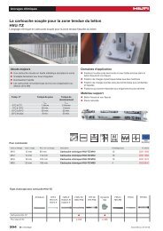
<strong>Anchor</strong> <strong>technology</strong> <strong>and</strong> <strong>design</strong><br />
<strong>Anchor</strong> selector<br />
Legal environment<br />
Approvals<br />
Base Material<br />
<strong>Anchor</strong> <strong>design</strong><br />
Design examples<br />
Corrosion<br />
Dynamic<br />
Resistance to fire<br />
Mechanical anchoring systems<br />
Heavy duty anchors<br />
Medium <strong>and</strong> light duty anchors<br />
Insulation fasteners<br />
Adhesive anchoring systems<br />
Foil capsule systems<br />
Injection mortar systems<br />
Post installed rebar connections<br />
Basics of post installed rebar connections<br />
<strong>Hilti</strong> HIT-RE 500 post installed rebar<br />
<strong>Hilti</strong> HIT-HY 150 post installed rebar<br />
<strong>Hilti</strong> HIT- HY 150 MAX post installed rebar<br />
11 / 2010<br />
Contents<br />
3
Contents<br />
Contents<br />
<strong>Anchor</strong> <strong>technology</strong> <strong>and</strong> <strong>design</strong> ........................................................................... 7<br />
4<br />
<strong>Anchor</strong> selector ........................................................................................................................8<br />
Legal environment..................................................................................................................20<br />
Approvals ...............................................................................................................................22<br />
Base material .........................................................................................................................26<br />
<strong>Anchor</strong> <strong>design</strong> ........................................................................................................................32<br />
Design examples....................................................................................................................48<br />
Corrosion................................................................................................................................58<br />
Dynamic .................................................................................................................................62<br />
Resistance to fire....................................................................................................................68<br />
Mechanical anchoring systems......................................................................... 79<br />
HDA Design anchor................................................................................................................80<br />
HSL-3 Heavy duty anchor ......................................................................................................96<br />
HSC-A Safety anchor ...........................................................................................................108<br />
HSC-I Safety anchor.............................................................................................................120<br />
HST Stud anchor..................................................................................................................132<br />
HSA Stud anchor..................................................................................................................144<br />
HSV Stud anchor..................................................................................................................156<br />
HLC Sleeve anchor ..............................................................................................................160<br />
HAM Hard sleeve anchor .....................................................................................................166<br />
HUS-HR Screw anchor.........................................................................................................168<br />
HUS-H Screw anchor ...........................................................................................................188<br />
HUS 6 Screw anchor | Redundant fastening ......................................................................202<br />
HUS-P 6 / HUS-I 6 Screw anchor for application in precast prestressed hollow core slabs.210<br />
HUS 6 Screw anchor............................................................................................................216<br />
HKD Push-in anchor | Single anchor application................................................................222<br />
HKD Push-in anchor | Redundant fastening.......................................................................238<br />
HKV Push-in anchor | Single anchor application ................................................................246<br />
HUD-1 Universal anchor.......................................................................................................250<br />
HUD-L Universal anchor.......................................................................................................256<br />
HLD Light duty anchor..........................................................................................................260<br />
HRD-U 10 / - S 10 / -U 14 Frame anchor .............................................................................264<br />
HRD Frame anchor ..............................................................................................................270<br />
HPS-1 Impact anchor ...........................................................................................................286<br />
HHD-S Cavity anchor ...........................................................................................................290<br />
HSP / HFP Drywall plug .......................................................................................................292<br />
HA 8 Ring / hook anchor ......................................................................................................294<br />
DBZ Wedge anchor..............................................................................................................298<br />
HT Metal frame anchor.........................................................................................................302<br />
HK Ceiling anchor.................................................................................................................306<br />
HPD Aerated concrete anchor..............................................................................................312<br />
HKH Hollow deck anchor......................................................................................................318<br />
HTB Hollow wall metal anchor..............................................................................................322<br />
11 / 2010
11 / 2010<br />
Contents<br />
IDP Insulation fastener .........................................................................................................326<br />
IZ Insulation fastener............................................................................................................330<br />
IDMS / IDMR Insulation fastener ..........................................................................................334<br />
Adhesive anchoring systems.......................................................................... 339<br />
HVZ Adhesive anchor...........................................................................................................340<br />
HVU with HAS/HAS-E rod adhesive anchor.........................................................................354<br />
HVU with HIS-(R)N adhesive anchor....................................................................................366<br />
<strong>Hilti</strong> HIT-RE 500-SD with HIT-V rod......................................................................................378<br />
<strong>Hilti</strong> HIT-RE 500-SD with HIS-(R)N ......................................................................................404<br />
<strong>Hilti</strong> HIT-RE 500-SD with rebar.............................................................................................418<br />
<strong>Hilti</strong> HIT-RE 500 with HIT-V / HAS........................................................................................436<br />
<strong>Hilti</strong> HIT-RE 500 with HIS-(R)N ............................................................................................458<br />
<strong>Hilti</strong> HIT-RE 500 with rebar...................................................................................................472<br />
<strong>Hilti</strong> HIT-HY 150 MAX with HIT-TZ .......................................................................................492<br />
<strong>Hilti</strong> HIT-HY 150 MAX with HIT-V / HAS...............................................................................504<br />
<strong>Hilti</strong> HIT-HY 150 MAX with HIS-(R)N....................................................................................526<br />
<strong>Hilti</strong> HIT-HY 150 MAX with rebar ..........................................................................................538<br />
<strong>Hilti</strong> HIT-HY 150 with HIT-V / HAS........................................................................................558<br />
<strong>Hilti</strong> HIT-HY 150 with HIS .....................................................................................................578<br />
<strong>Hilti</strong> HIT-HY 150 with rebar...................................................................................................590<br />
<strong>Hilti</strong> HIT-ICE with HIT-V / HAS .............................................................................................606<br />
<strong>Hilti</strong> HIT-ICE with HIS ...........................................................................................................626<br />
<strong>Hilti</strong> HIT-ICE with rebar.........................................................................................................638<br />
<strong>Hilti</strong> HIT-HY 70 injection mortar for masonry ........................................................................654<br />
Post installed rebar connections .................................................................... 681<br />
Basics of post installed rebar connections............................................................................682<br />
<strong>Hilti</strong> HIT-RE 500 post installed rebars...................................................................................716<br />
<strong>Hilti</strong> HIT-HY 150 post installed rebars...................................................................................730<br />
<strong>Hilti</strong> HIT-HY 150 MAX post installed rebars..........................................................................738<br />
<strong>Hilti</strong> worldwide .................................................................................................. 746<br />
5
6<br />
<strong>Anchor</strong> <strong>technology</strong><br />
<strong>and</strong> <strong>design</strong><br />
11 / 2010
<strong>Anchor</strong> <strong>technology</strong> <strong>and</strong> <strong>design</strong><br />
<strong>Anchor</strong> selector<br />
Legal environment<br />
Approvals<br />
Base Material<br />
<strong>Anchor</strong> <strong>design</strong><br />
Design examples<br />
Corrosion<br />
Dynamic<br />
Resistance to fire<br />
11 / 2010<br />
<strong>Anchor</strong> <strong>technology</strong><br />
<strong>and</strong> <strong>design</strong><br />
7
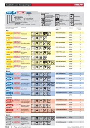
<strong>Anchor</strong> selector<br />
<strong>Anchor</strong> selector<br />
8<br />
<strong>Anchor</strong> type<br />
Base material<br />
Cracked concrete<br />
Mechanical anchor systems<br />
Heavy duty anchors<br />
HDA-T/ -TR/TF/-P/-PR/-PF<br />
undercut anchor<br />
HSL-3 heavy duty anchor<br />
Medium <strong>and</strong> light duty<br />
anchors<br />
HSC-A(R) /-I(R) safety anchor<br />
HST/-R/-HCR stud anchor<br />
HSA/-R/-F stud anchor<br />
HSV stud anchor<br />
HLC sleeve anchor<br />
HAM hard sleeve anchor<br />
Uncracked concrete<br />
● ●<br />
● ●<br />
● ●<br />
● ●<br />
●<br />
●<br />
●<br />
Lightweight concrete<br />
Aerated concrete<br />
Solid brick masonry<br />
● ●<br />
Hollow brick masonry<br />
Pre-stressed concrete hollow deck<br />
Approval<br />
Approval for dynamic loads<br />
Fire tested<br />
Application<br />
● ● ● <strong>Anchor</strong> fastening for high loads e.g.<br />
in steel construction <strong>and</strong> plant<br />
construction, suitable for dynamic<br />
loading<br />
● ● Fastening heavy loads e.g. from<br />
columns, high racks, machines<br />
● ● Safety relevant fastening at facades<br />
<strong>and</strong> ceilings where short embedment<br />
depth is required<br />
● ● Fastening through in place parts e.g.<br />
angles, tracks, channels, wooden<br />
beams, etc.<br />
● ● Fastening through in place parts like<br />
wooden beams, metal sections,<br />
columns, brackets, etc.<br />
Fastening through in place parts<br />
● ● Temporary fastenings in concrete<br />
(e.g. formwork), fastening in base<br />
material of low density<br />
● = very suitable ○ = may be suitable per application 1) redundant fastening<br />
Secure fastenings in various base<br />
materials<br />
11 / 2010
Advantages<br />
� Automatic undercutting<br />
� High load capacity<br />
� Approved for dynamic loads<br />
� Integrated plastic section to<br />
telescope <strong>and</strong> pull down tightly<br />
� The bolt can be retorqued<br />
� Automatic undercutting<br />
� Small edge distances <strong>and</strong><br />
spacings<br />
� Small setting depth<br />
� Quick <strong>and</strong> simple setting<br />
operation<br />
� Setting mark<br />
� Safety wedge for certain follow<br />
11 / 2010<br />
up expansion<br />
� Two setting depths<br />
� Setting mark<br />
� Extremely ductile steel for high<br />
bending capacity<br />
� Quick <strong>and</strong> simple setting<br />
operation<br />
� Short setting <strong>and</strong> removing<br />
operation<br />
� Good loads in green concrete<br />
� Bridging of gaps<br />
� Wings to prevent spinning in the<br />
bore hole<br />
� Plastic cap in cone to prevent<br />
dust entrance<br />
Drill bit<br />
diameter resp.<br />
anchor size<br />
Drill bit dia.:<br />
20 – 37 mm<br />
<strong>Anchor</strong> size:<br />
M10 – M20<br />
Drill bit dia.:<br />
12 – 32 mm<br />
<strong>Anchor</strong> size:<br />
M8 – M24<br />
Drill bit dia.:<br />
14 – 20 mm<br />
<strong>Anchor</strong> size:<br />
M6 – M12<br />
Drill bit dia.:<br />
8 – 24 mm<br />
<strong>Anchor</strong> size:<br />
M8 – M24<br />
Drill bit dia.:<br />
6 – 20 mm<br />
<strong>Anchor</strong> size:<br />
M8 – M24<br />
Drill bit dia.:<br />
8 – 16 mm<br />
<strong>Anchor</strong> size:<br />
M8 – M16<br />
Drill bit dia.:<br />
6,5 – 20 mm<br />
<strong>Anchor</strong> size:<br />
M5 – M16<br />
Drill bit dia.:<br />
12 – 20 mm<br />
Thread:<br />
M6 – M12<br />
Steel, galvanised<br />
Steel, sheradised, hot dipped galv.<br />
● ●<br />
●<br />
●<br />
●<br />
● ●<br />
●<br />
●<br />
●<br />
Specification Setting<br />
Stainless steel A2 (1.4303)<br />
Stainless steel A4 (1.4401)<br />
HCR steel (1.4529)<br />
External thread<br />
Internal thread<br />
<strong>Anchor</strong> selector<br />
Pre-setting<br />
Through-fastening<br />
Page<br />
● ● ● ● 80<br />
● ● 96<br />
● ● ● ● 108<br />
● ● ● ● ● 132<br />
● ● ● 144<br />
● ● ● 156<br />
● ● ● 160<br />
● ● 166<br />
9
<strong>Anchor</strong> selector<br />
<strong>Anchor</strong> type<br />
Medium <strong>and</strong> light duty<br />
anchors<br />
HUS-HR screw anchor<br />
HUS-H screw anchor<br />
HUS-P 6, HUS-I 6 screw anchor<br />
HUS 6 screw anchor<br />
HKD push-in anchor<br />
HKV push-in anchor<br />
HUD-1 universal anchor<br />
HUD-L universal anchor<br />
HLD light duty anchor<br />
10<br />
Base material<br />
Cracked concrete<br />
Uncracked concrete<br />
● ●<br />
● ●<br />
●<br />
1)<br />
●<br />
1)<br />
●<br />
1)<br />
Lightweight concrete<br />
Aerated concrete<br />
Solid brick masonry<br />
Hollow brick masonry<br />
Pre-stressed concrete hollow deck<br />
Approval<br />
Approval for dynamic loads<br />
Fire tested<br />
Application<br />
● ● ● Fastening channels, brackets, racks,<br />
seating<br />
● ● ● Fastening channels, brackets, racks,<br />
seating<br />
● ● ● ● Fastening channels, brackets, racks,<br />
seating<br />
● ● ● ● ● ●<br />
●<br />
●<br />
● ● ● ● ● ●<br />
● ● ● ● ● ●<br />
● ● ●<br />
● = very suitable ○ = may be suitable per application 1) redundant fastening<br />
● Fastening light channels, brackets,<br />
interior panelling or cladding<br />
● ● Fastening with threaded rods for<br />
pipe suspensions, air ducts,<br />
suspended ceilings<br />
Fastening with threaded rods for<br />
pipe suspensions, air ducts,<br />
suspended ceilings<br />
Various applications<br />
Various applications<br />
Fastenings to weak material with<br />
cavities<br />
11 / 2010
Advantages<br />
� Screw driven straight into base<br />
material<br />
� Forged on washer<br />
� Matched system of screw<br />
11 / 2010<br />
anchor <strong>and</strong> screw driver<br />
� Screw driven straight into base<br />
material<br />
� Forged on washer<br />
� Matched system of screw<br />
anchor <strong>and</strong> screw driver<br />
� Screw driven straight into base<br />
material<br />
� Forged on washer<br />
� Matched system of screw<br />
anchor <strong>and</strong> screw driver<br />
� Screw driven straight into base<br />
material<br />
� Small drill bit diameter<br />
� Matched system of screw<br />
anchor <strong>and</strong> screw driver<br />
� Visual verification of full<br />
expansion<br />
� Small setting depth<br />
� Visual verification of full<br />
expansion<br />
� Small setting depth<br />
� Fast setting<br />
� Flexibility of screw length<br />
� An anchor for every base<br />
material<br />
� Fast setting<br />
� Flexibility of screw length<br />
� An anchor for every base<br />
material<br />
� Flexibility of screw length<br />
� Resilient toggling action to suit<br />
every base material<br />
Drill bit<br />
diameter resp.<br />
anchor size<br />
Drill bit dia.:<br />
6 – 14 mm<br />
Drill bit dia.:<br />
8 – 14 mm<br />
Drill bit dia.:<br />
6 mm<br />
Drill bit dia.:<br />
6 mm<br />
Drill bit dia.:<br />
8 – 25 mm<br />
<strong>Anchor</strong> size:<br />
M6 – M20<br />
Drill bit dia.:<br />
8 – 25 mm<br />
<strong>Anchor</strong> size:<br />
M6 – M20<br />
Drill bit dia.:<br />
5 – 14 mm<br />
Drill bit dia.:<br />
6 – 10 mm<br />
Drill bit dia.:<br />
10 mm<br />
Steel, galvanised<br />
●<br />
●<br />
●<br />
●<br />
●<br />
Steel, sheradised, hot dipped galv.<br />
Specification Setting<br />
Stainless steel A2 (1.4303)<br />
Stainless steel A4 (1.4401)<br />
●<br />
HCR steel (1.4529)<br />
External thread<br />
Internal thread<br />
<strong>Anchor</strong> selector<br />
Pre-setting<br />
Through-fastening<br />
Page<br />
● 168<br />
● 188<br />
● ● 202<br />
● ● 216<br />
● ● ● 222<br />
● ● 246<br />
● ● 250<br />
● ● 256<br />
● 260<br />
11
<strong>Anchor</strong> selector<br />
<strong>Anchor</strong> type<br />
12<br />
Base material<br />
Medium <strong>and</strong> light duty<br />
anchors<br />
HRD-U/-S frame anchor ● ● ● ● ● ●<br />
HRD frame anchor<br />
HPS-1 impact anchor<br />
HHD cavity anchor<br />
HSP/HFPdrywall plug<br />
HA8 ring/ hook anchor<br />
DBZ wedge anchor<br />
HT metal frame anchor<br />
HK ceiling anchor<br />
HPD aerated concrete anchor<br />
Cracked concrete<br />
●<br />
1)<br />
●<br />
1)<br />
●<br />
1)<br />
●<br />
1)<br />
Uncracked concrete<br />
Lightweight concrete<br />
Aerated concrete<br />
Solid brick masonry<br />
Hollow brick masonry<br />
Pre-stressed concrete hollow deck<br />
● ● ● ●<br />
● ○ ○ ● ○<br />
● ●<br />
● ● ●<br />
● ● ●<br />
● ● ● ●<br />
●<br />
Approval<br />
Approval for dynamic loads<br />
Fire tested<br />
Application<br />
● = very suitable ○ = may be suitable per application 1) redundant fastening<br />
●<br />
● Securing support frames, timber<br />
frames, fascade panels, curtain<br />
walling<br />
● On most hollow <strong>and</strong> solid base<br />
material<br />
Fastening wood battens,<br />
components for electrical <strong>and</strong><br />
plumbing installations<br />
Fastening battens, channels panels<br />
Fastenings in dry walls<br />
● For suspended ceilings <strong>and</strong> other<br />
items from concrete ceilings<br />
● Suspension from concrete ceilings<br />
e.g. using steel straps, punched<br />
b<strong>and</strong>, Nonius system hanger<br />
Fastening door <strong>and</strong> window frames<br />
● ● Fastening of suspended ceilings,<br />
cable trays, pipes<br />
● ● Various fastenings in hollow decks<br />
11 / 2010
Advantages<br />
� Preassembled with screw<br />
� Screw of steel 5.8 grade or<br />
stainless steel A4 (1.4401)<br />
� impact <strong>and</strong> temperature<br />
resistant<br />
� high quality plastic<br />
� impact <strong>and</strong> temperature<br />
resistant<br />
� high quality plastic<br />
� Controlled setting<br />
� Deliverable with or without<br />
prefitted screw<br />
� Self-drilling tip<br />
� One bit for anchor <strong>and</strong> screw<br />
� Removable<br />
� Quick <strong>and</strong> easy setting<br />
� Automatic follow up expansion<br />
� Small drill bit diameter<br />
� Quick setting by impact<br />
extension<br />
� Automatic follow up expansion<br />
� No risk of distortion or forces of<br />
constraint<br />
� Expansion cone can not be lost<br />
� Small bore hole<br />
� Quick <strong>and</strong> easy setting<br />
� Approved (DIBt)<br />
� Fire resistance<br />
� Immediately loadable<br />
11 / 2010<br />
Drill bit<br />
diameter resp.<br />
anchor size<br />
Drill bit dia.:<br />
10 <strong>and</strong> 14 mm<br />
Drill bit dia.:<br />
8 mm<br />
Steel, galvanised<br />
Steel, sheradised, hot dipped galv.<br />
Specification Setting<br />
Stainless steel A2 (1.4303)<br />
Stainless steel A4 (1.4401)<br />
● ●<br />
● ●<br />
4 – 8 mm ● ●<br />
Drill bit dia.:<br />
8 – 12 mm<br />
-<br />
Drill bit dia.:<br />
8 mm<br />
Drill bit dia.:<br />
6 mm<br />
Drill bit dia.:<br />
8 – 10 mm<br />
Drill bit dia.:<br />
6 mm<br />
M6<br />
Without<br />
predrilling<br />
Thread:<br />
M6 – M10<br />
●<br />
●<br />
●<br />
●<br />
●<br />
●<br />
HCR steel (1.4529)<br />
External thread<br />
Internal thread<br />
<strong>Anchor</strong> selector<br />
Pre-setting<br />
Through-fastening<br />
Page<br />
● 264<br />
● 270<br />
● ● 282<br />
● 286<br />
● 288<br />
● 290<br />
● 294<br />
● 298<br />
● ● 302<br />
● ● 308<br />
13
<strong>Anchor</strong> selector<br />
<strong>Anchor</strong> type<br />
Medium <strong>and</strong> light duty<br />
anchors<br />
HKH hollow deck anchor<br />
HTB<br />
Insulation fasteners<br />
IDP insulation<br />
fastener<br />
IZ exp<strong>and</strong>able insulation fastener<br />
IDMS / IDMR insulation fastener<br />
14<br />
Base material<br />
Cracked concrete<br />
Uncracked concrete<br />
Lightweight concrete<br />
Aerated concrete<br />
Solid brick masonry<br />
● ● ●<br />
Hollow brick masonry<br />
● ● ● ●<br />
● ● ● ●<br />
● = very suitable ○ = may be suitable per application<br />
Pre-stressed concrete hollow deck<br />
Approval<br />
Approval for dynamic loads<br />
Fire tested<br />
Application<br />
● ● ● Suspension from pre-stressed<br />
concrete hollow decks<br />
● ● Ingenious <strong>and</strong> strong for hollow<br />
base materials<br />
Fastening of hard, self supporting<br />
insulating materials<br />
Fastening of soft <strong>and</strong> hard, self<br />
supporting insulating materials<br />
Fastening of soft <strong>and</strong> hard, self<br />
supporting insulating materials <strong>and</strong><br />
non self supporting insulation<br />
materials<br />
11 / 2010
Advantages<br />
� Approval for single point<br />
fastenings<br />
� Approved for sprinkler systems<br />
� Load carried by strong metal<br />
channel <strong>and</strong> screw<br />
� Convincing simplicity when<br />
setting<br />
� One piece element<br />
� Corrosion resistant<br />
� No heat bridge<br />
� Corrosion resistant<br />
� No heat bridge<br />
� Reliable bonding of plaster<br />
� One piece element<br />
� Corrosion resistant<br />
� Fire resistant<br />
11 / 2010<br />
Drill bit<br />
diameter resp.<br />
anchor size<br />
Drill bit dia.:<br />
10 – 14 mm<br />
Thread:<br />
M6 – M10<br />
Drill bit dia.:<br />
13 – 14 mm<br />
Drill bit dia.:<br />
8 mm insulating<br />
material<br />
thickness<br />
10 – 150mm<br />
Drill bit dia.:<br />
8 mm insulating<br />
material<br />
thickness<br />
up to 180mm<br />
Drill bit dia.:<br />
8 mm insulating<br />
material<br />
thickness<br />
up to 150mm<br />
Steel, galvanised<br />
●<br />
Steel, sheradised, hot dipped galv.<br />
● ●<br />
Specification Setting<br />
Stainless steel A2 (1.4303)<br />
Stainless steel A4 (1.4401)<br />
HCR steel (1.4529)<br />
External thread<br />
Internal thread<br />
<strong>Anchor</strong> selector<br />
Pre-setting<br />
Through-fastening<br />
Page<br />
● ● ● 314<br />
● 318<br />
● 322<br />
● 326<br />
● 330<br />
15
<strong>Anchor</strong> selector<br />
<strong>Anchor</strong> type<br />
Adhesive anchor<br />
systems<br />
Foil capsule systems<br />
HVZ<br />
adhesive<br />
anchor<br />
HVU<br />
adhesive<br />
anchor<br />
Injection mortar systems<br />
HIT-RE<br />
500–SD<br />
HIT-RE<br />
500<br />
16<br />
Base material<br />
Cracked concrete<br />
Uncracked concrete<br />
Lightweight concrete<br />
● ● ●<br />
●<br />
● ●<br />
Aerated concrete<br />
Solid brick masonry<br />
● = very suitable ○ = may be suitable per application<br />
●<br />
Hollow brick masonry<br />
Pre-stressed concrete hollow deck<br />
Approval<br />
Approval for dynamic loads<br />
Fire tested<br />
Application<br />
● ● ● Heavy-duty fastenings with small<br />
spacing <strong>and</strong> edge distances<br />
● ● Heavy duty fastenings with small<br />
spacing <strong>and</strong> edge distances<br />
● ● Adhesive anchor in cracked<br />
concrete<br />
● ● Adhesive anchor<br />
11 / 2010
Advantages<br />
� No expansion pressure<br />
� Small edge distances <strong>and</strong><br />
spacing<br />
� A strong <strong>and</strong> flexible foil capsule<br />
� No expansion pressure<br />
� Small edge distances <strong>and</strong><br />
spacing<br />
� A strong <strong>and</strong> flexible foil capsule<br />
� Flexibility in terms of working<br />
time<br />
� No expansion pressure<br />
� Flexibility in terms of drill bit<br />
diameter <strong>and</strong> annular gap<br />
� Flexibility in terms of working<br />
time<br />
11 / 2010<br />
Drill bit<br />
diameter resp.<br />
anchor size<br />
Steel, galvanised<br />
M10 – M20 ●<br />
HAS M8 – M39<br />
HIS-M8 - M20<br />
Rebar dia.<br />
8 – 40 mm<br />
HAS M8 – M30<br />
HIS-M8 - M20<br />
Rebar dia.<br />
8 – 32 mm<br />
HAS M8 – M39<br />
HIS-M8 - M20<br />
Rebar dia.<br />
8 – 40 mm<br />
●<br />
●<br />
●<br />
Steel, sheradised, hot dipped galv.<br />
Specification Setting<br />
Stainless steel A2 (1.4303)<br />
Stainless steel A4 (1.4401)<br />
HCR steel (1.4529)<br />
External thread<br />
Internal thread<br />
<strong>Anchor</strong> selector<br />
Pre-setting<br />
Through-fastening<br />
Page<br />
● ● ● ● 336<br />
● ● ● ● ● 350<br />
● ● ● ● ● 374<br />
● ● ● ● ● 432<br />
17
<strong>Anchor</strong> selector<br />
<strong>Anchor</strong> type<br />
Injection mortar systems<br />
HIT-HY<br />
150 MAX<br />
HIT-HY<br />
150<br />
HIT ICE<br />
HIT-HY<br />
70<br />
18<br />
Base material<br />
Cracked concrete<br />
Uncracked concrete<br />
Lightweight concrete<br />
● ●<br />
● ●<br />
Aerated concrete<br />
Solid brick masonry<br />
● = very suitable ○ = may be suitable per application<br />
○<br />
Hollow brick masonry<br />
Pre-stressed concrete hollow deck<br />
Approval<br />
Approval for dynamic loads<br />
Fire tested<br />
Application<br />
● Adhesive anchor in cracked<br />
concrete<br />
● ● Adhesive anchor<br />
Adhesive anchor for low installation<br />
temperatures<br />
● ● ● Universal mortar for solid <strong>and</strong> hollow<br />
brick<br />
11 / 2010
Advantages<br />
� No expansion pressure<br />
� No styrene content<br />
� No plasticizer content<br />
� Environmental protection due to<br />
the minimized packaging<br />
� No expansion pressure<br />
� No styrene content<br />
� No plasticizer content<br />
� Environmental protection due to<br />
the minimized packaging<br />
11 / 2010<br />
Drill bit<br />
diameter resp.<br />
anchor size<br />
HAS M8 – M30<br />
HIS-M8 - M20<br />
Rebar dia.<br />
8 – 25 mm<br />
HAS M8 – M30<br />
HIS-M8 - M20<br />
Rebar dia.<br />
8 – 25 mm<br />
� No expansion pressure HAS M8 – M24<br />
HIS-M8 - M20<br />
Rebar dia.<br />
8 – 25 mm<br />
� No expansion pressure<br />
� mortar filling control<br />
with HIT-SC sleeves<br />
Drill bit dia.:<br />
10 – 22 mm<br />
Thread:<br />
M6 – M12<br />
Steel, galvanised<br />
●<br />
●<br />
●<br />
Steel, sheradised, hot dipped galv.<br />
Specification Setting<br />
Stainless steel A2 (1.4303)<br />
Stainless steel A4 (1.4401)<br />
HCR steel (1.4529)<br />
External thread<br />
Internal thread<br />
<strong>Anchor</strong> selector<br />
Pre-setting<br />
Through-fastening<br />
Page<br />
● ● ● ● 488<br />
● ● ● ● 554<br />
602<br />
● ● ● ● 650<br />
19
Legal environment<br />
Legal environment<br />
Technical data<br />
The technical data presented in this <strong>Anchor</strong> Fastening Technology Manual are all based on<br />
numerous tests <strong>and</strong> evaluation according to the state-of-the art. <strong>Hilti</strong> anchors are tested in our<br />
test labs in Kaufering (Germany), Schaan (Principality of Liechtenstein) or Tulsa (USA) <strong>and</strong><br />
evaluated by our experienced engineers <strong>and</strong>/or tested <strong>and</strong> evaluated by independent testing<br />
institutes in Europe <strong>and</strong> the USA. Where national or international regulations do not cover all<br />
possible types of applications, additional <strong>Hilti</strong> data help to find customised solutions.<br />
In addition to the st<strong>and</strong>ard tests for admissible service conditions <strong>and</strong> suitability tests, for safety<br />
relevant applications fire resistance, shock, seismic <strong>and</strong> fatigue tests are performed.<br />
European Technical Approval Guidelines<br />
Approval based data given in this manual are either according to European Technical Approval<br />
Guidelines (ETAG) or have been evaluated according to this guidelines <strong>and</strong>/or national<br />
regulations.<br />
The European Technical Approval Guideline ETAG 001 „METAL ANCHORS FOR USE IN<br />
CONCRETE“ sets out the basis for assessing anchors to be used in concrete (cracked <strong>and</strong> noncracked).<br />
It consists of:<br />
� Part 1 <strong>Anchor</strong>s in general<br />
� Part 2 Torque-controlled expansion anchors<br />
� Part 3 Undercut anchors<br />
� Part 4 Deformation-controlled expansion anchors<br />
� Part 5 Bonded anchors<br />
� Part 6 <strong>Anchor</strong>s for multiple use for non-structural applications<br />
� Annex A Details of test<br />
� Annex B Tests for admissible service conditions – detailed information<br />
� Annex C Design methods for anchorages<br />
For special anchors for use in concrete, additional Technical Reports (TR) related to ETAG 001<br />
set out additional requirements:<br />
� TR 018 Assessment of torque-controlled bonded anchors<br />
� TR 020 Evaluation of <strong>Anchor</strong>ages in Concrete concerning Resistance to Fire<br />
� TR 029 Design of Bonded <strong>Anchor</strong>s<br />
The European Technical Approval Guideline ETAG 020 „ PLASTIC ANCHORS FOR<br />
MULTIPLE USE IN CONCRETE AND MASONRY FOR NON-STRUCTURAL APPLICATIONS“<br />
sets out the basis for assessing plastic anchors to be used in concrete or masonry for<br />
redundant fastenings (multiple use). It consists of:<br />
� Part 1 General<br />
� Part 2 Plastic anchors for use in normal weight concrete<br />
� Part 3 Plastic anchors for use in solid masonry materials<br />
� Part 4 Plastic anchors for use in hollow or perforated masonry<br />
� Part 5 Plastic anchors for use in autoclaved aerated concrete (AAC)<br />
� Annex A Details of tests<br />
� Annex B Recommendations for tests to be carried out on construction works<br />
� Annex C Design methods for anchorages<br />
20<br />
11 / 2010
11 / 2010<br />
Legal environment<br />
The European Technical Approval Guidelines including related Technical Reports set out the<br />
requirements for anchors <strong>and</strong> the acceptance criteria they shall meet.<br />
The general assessment approach adopted in the Guideline is based on combining relevant<br />
existing knowledge <strong>and</strong> experience of anchor behaviour with testing. Using this approach,<br />
testing is needed to assess the suitability of anchors.<br />
The requirements in European Technical Approval Guidelines are set out in terms of objectives<br />
<strong>and</strong> of relevant actions to be taken into account. ETAGs specify values <strong>and</strong> characteristics, the<br />
conformity with which gives the presumption that the requirements set out are satisfied,<br />
whenever the state of art permits to do so. The Guidelines may indicate alternate possibilities<br />
for the demonstration of the satisfaction of the requirements.<br />
Post installed rebar connections<br />
The basis for the assessment of post installed rebar connections is set out in the Technical<br />
Report<br />
� TR 023 Assessment of post-installed rebar connections<br />
The Technical Report TR 023 covers post-installed rebar connections <strong>design</strong>ed in accordance<br />
with EN 1992 - 1-1: 2004 (EC2) only. ETAG 001 (Part 1 <strong>and</strong> Part 5) is the general basic of this<br />
application. The Technical Report TR 023 deals with the preconditions, assumptions <strong>and</strong> the<br />
required tests <strong>and</strong> assessments for postinstalled rebars.<br />
System of attestation of conformity<br />
For anchors having an approval, the conformity of the product shall be certified by an approved<br />
certification body (notified body) on the basis of tasks for the manufacturer <strong>and</strong> tasks for the<br />
approved body.<br />
Tasks for the manufacturer are:<br />
� Factory production control (permanent internal control of production <strong>and</strong> documentation<br />
according to a prescribed test plan)<br />
� involve a body which is approved for the tasks<br />
Tasks for the approved body are:<br />
� initial type-testing of the product<br />
� initial inspection of factory <strong>and</strong> of factory production control<br />
� continuous surveillance, assessment <strong>and</strong> approval of factory production control<br />
21
Approvals<br />
Approvals<br />
International Approvals: Europe<br />
<strong>Anchor</strong> type Description Authority /<br />
Laboratory<br />
HDA / HDA-R Self-undercutting anchor made of<br />
galvanised or stainless steel<br />
(Valid until: 25.03.2013)<br />
HSL-3 Torque controlled expansion anchor<br />
of galvanised steel<br />
(Valid until: 10.01.2013)<br />
HSC / HSC-R Self-undercutting anchor made of<br />
galvanised or stainless steel<br />
(Valid until: 20.09.2012)<br />
HST / HST-R /<br />
HST-HCR<br />
22<br />
Expansion stud anchor made of<br />
galvanised, stainless or highly<br />
corrosion resistant steel<br />
(Valid until: 19.02.2013)<br />
HSA / HSA-R Expansion stud anchor made of<br />
galvanised or stainless steel<br />
(Valid until: 13.03.2013)<br />
HUS-HR<br />
6/8/10/14<br />
HUS-H<br />
8/10<br />
Screw anchor made of stainless<br />
steel,<br />
(Valid until: 12.12.2013)<br />
Screw anchor made of carbon steel,<br />
deltatone coated<br />
(Valid until: 12.12.2013)<br />
HUS 6 Screw anchor made of carbon steel,<br />
deltatone coated<br />
(Valid until: 23.04.2015)<br />
HKD / HKD-R Deformation controlled expansion<br />
anchor made of galvanised or<br />
stainless steel<br />
(Vailid until: 22.04.2015)<br />
HKD / HKD-R Deformation controlled expansion<br />
anchor made of galvanised or<br />
stainless steel<br />
(Vailid until: 22.04.2015)<br />
HRD Frame anchor made of polyamide,<br />
screw made of galvanised or<br />
stainless steel<br />
(Valid until: 17.09.2012)<br />
DBZ Wedge anchor made of galvanised<br />
steel<br />
(Valid until: 13.09.2011)<br />
HK Ceiling anchor made of galvanised<br />
steel (Valid until: 23.04.2014)<br />
HVZ / HVZ-R /<br />
HVZ-HCR<br />
HVU with<br />
HAS / HIS-N<br />
Adhesive anchor, rod made of<br />
galvanised, stainless or highly<br />
corrosion resistant steel<br />
(Valid until: 01.10.2013)<br />
Adhesive anchor, rod made out of<br />
galvanised steel<br />
(Valid until 20.01.2011)<br />
No. /<br />
Languages<br />
Date of issue g e f<br />
CSTB, Paris ETA-99/0009<br />
25.03.2008<br />
� � �<br />
CSTB, Paris ETA-02/0042<br />
10.01.2008<br />
CSTB, Paris ETA-02/0027<br />
20.09.2007<br />
DIBt, Berlin ETA-98/0001<br />
07.07.2009<br />
CSTB, Paris ETA-99/0001<br />
13.03.2008<br />
DIBt, Berlin ETA-08/307<br />
30.03.2009<br />
DIBt, Berlin ETA-08/307<br />
30.03.2009<br />
DIBt, Berlin ETA-10/0005<br />
23.04.2010<br />
DIBt, Berlin ETA-06/0047<br />
22.04.2010<br />
DIBt, Berlin ETA-02/0032<br />
22.04.2010<br />
DIBt, Berlin ETA-07/0219<br />
12.08.2010<br />
DIBt, Berlin ETA-06/0179<br />
13.09.2006<br />
DIBt, Berlin ETA-04/0043<br />
05.05.2009<br />
DIBt, Berlin ETA-03/0032<br />
29.09.2008<br />
DIBt Berlin ETA-05/0255<br />
01.03.2010<br />
� � �<br />
� � �<br />
� � �<br />
� � �<br />
� � �<br />
� � �<br />
� �<br />
� �<br />
� �<br />
� � �<br />
� �<br />
� �<br />
� �<br />
� �<br />
11 / 2010
<strong>Anchor</strong> type Description Authority /<br />
Laboratory<br />
HVU with<br />
HAS-R / HIS-RN<br />
HVU with<br />
HAS-HCR<br />
HIT-RE 500-SD<br />
with HIT-V/<br />
HIS-N/<br />
HIT-V-R/ HIS-<br />
RN/ HIT-V-HCR/<br />
rebar BSt 500S<br />
HIT-RE 500 with<br />
HIT-V/ HAS-(E)/<br />
HIS-N/<br />
HIT-V-R/ HAS-<br />
(E)R/ HIS-RN/<br />
HIT-V-HCR/<br />
HAS-(E)HCR<br />
HIT-HY 150 MAX<br />
with HIT-TZ /<br />
HIT-RTZ<br />
HIT-HY 150 MAX<br />
with HIT-V/ HAS-<br />
(E)/ HIS-N/<br />
HIT-V-R/ HAS-<br />
(E)R/ HIS-RN/<br />
HIT-V-HCR/<br />
HAS-(E)HCR<br />
HIT-HY 150 with<br />
HIT-V/ HAS-(E)/<br />
HIS-N/<br />
HIT-V-R/ HAS-<br />
(E)R/ HIS-RN/<br />
HIT-V-HCR/<br />
HAS-(E)HCR<br />
11 / 2010<br />
Adhesive anchor, rod made out of<br />
stainless steel<br />
(Valid until 20.01.2011)<br />
Adhesive anchor, rod made out of<br />
highly corrosion resistant steel<br />
(Valid until 20.01.2011)<br />
Injection adhesive anchor, rod made<br />
of galvanised, stainless or highly<br />
corrosion resistant steel<br />
(Valid until 08.11.2012)<br />
Injection adhesive anchor, rod made<br />
of galvanised, stainless or highly<br />
corrosion resistant steel<br />
(Valid until 28.05.2014)<br />
Injection adhesive anchor, rod made<br />
of galvanised or stainless steel<br />
(Valid until 23.09.2014)<br />
Injection adhesive anchor, rod made<br />
of galvanised, stainless or highly<br />
corrosion resistant steel<br />
(Valid until 18.12.2013)<br />
Injection adhesive anchor, rod made<br />
of galvanised, stainless or highly<br />
corrosion resistant steel<br />
(Valid until 17.03.2011)<br />
Additional National European Approvals<br />
France<br />
<strong>Anchor</strong> type Description Authority /<br />
Laboratory<br />
HPS-1 Impact anchor made of Polyamide,<br />
nail made of galvanised steel<br />
(Valid until: 30.09.2008)<br />
HIT-HY 70 Injection adhesive, rod made of<br />
galvanised steel<br />
(Valid until: 30.06.2012)<br />
Approvals<br />
No. /<br />
Languages<br />
Date of issue g e f<br />
DIBt Berlin ETA-05/0256<br />
20.01.2006<br />
� � �<br />
DIBt Berlin ETA-05/0257<br />
20.01.2006<br />
DIBt Berlin ETA-07/0260<br />
12.01.2009<br />
DIBt Berlin ETA-04/0027<br />
20.05.2009<br />
DIBt Berlin ETA-04/0084<br />
09.12.2009<br />
CSTB, Paris ETA-08-352<br />
01.04.2010<br />
DIBt Berlin ETA-05/0051<br />
22.10.2008<br />
� � �<br />
� �<br />
� �<br />
� � �<br />
� � �<br />
� �<br />
No. /<br />
Languages<br />
Date of issue g e f<br />
SOCOTEC, Paris CX 5217<br />
08.2000<br />
�<br />
SOCOTEC, Paris YX 0047 06.2009 �<br />
23
Approvals<br />
Germany<br />
<strong>Anchor</strong> type Description Authority /<br />
Laboratory<br />
HDA Self-undercutting anchor made of<br />
galvanised steel for unusual actions<br />
(loads) – for use in Nuclear power<br />
plants) (Valid until: 31.03.2011)<br />
HDA- Dynamic Self-undercutting anchor made of<br />
galvanised steel for dynamic loads<br />
(Valid until: 30.09.2011)<br />
HUS,-H/-A 6 Screw anchor made of galvanised<br />
steel (Valid until: 31.07.2012)<br />
HRD Frame anchor made of polyamide,<br />
screw made of galvanised or<br />
stainless steel<br />
(Valid until: 31.10.2012)<br />
HK Ceiling anchor made of galvanised or<br />
stainless steel<br />
(Valid until: 31.01.2010)<br />
HPD Aerated concrete anchor made of<br />
galvanised steel<br />
(Valid until: 31.05.2011)<br />
HKH Hollow deck anchor made of<br />
galvanised steel<br />
(Valid until: 31.10.2011)<br />
HVZ-Dynamic Adhesive anchor, rod made of<br />
galvanised steel<br />
(Valid until:31.10.2011)<br />
HIT-RE 500 Injection adhesive for reinforcing bar<br />
connections (Valid until: 23.10.2010)<br />
HIT-HY 150 MAX Injection adhesive for reinforcing bar<br />
connections (Valid until: 30.11.2014)<br />
HIT-HY 70 Injection adhesive anchor for<br />
masonry, rod made of galvanised,<br />
stainless or highly corrosion<br />
resistant steel<br />
(Valid until: 30.11.2011)<br />
24<br />
No. /<br />
Date of issue<br />
DIBt, Berlin Z-21.1-1696<br />
01.09.2008<br />
DIBt, Berlin Z-21.1-1693<br />
25.05.2007<br />
DIBt, Berlin Z-21.1-1710<br />
20.05.2009<br />
DIBt, Berlin Z-21.2-599<br />
25.10.2007<br />
DIBt, Berlin Z-21.1-1721<br />
29.08.2006<br />
DIBt, Berlin Z-21.1-1729<br />
18.04.2007<br />
DIBt, Berlin Z-21.1-1722<br />
21.10.2008<br />
DIBt, Berlin Z-21.3-1692<br />
18.10.2006<br />
DIBt, Berlin Z-21.8-1790<br />
16.03.2009<br />
DIBt, Berlin Z-21.8-1882<br />
16.12.2009<br />
DIBt, Berlin Z-21.3-1830<br />
20.01.2009<br />
Languages<br />
g<br />
�<br />
e f<br />
�<br />
�<br />
�<br />
�<br />
�<br />
�<br />
�<br />
�<br />
�<br />
�<br />
11 / 2010
Switzerl<strong>and</strong><br />
<strong>Anchor</strong> type Description Authority /<br />
Laboratory<br />
HDA / HDA-R Undercut anchor for shockproof<br />
fastenings in civil defence<br />
installations<br />
HSL-3<br />
HSL-3-G<br />
HSL-3-B<br />
HSL-3-SK<br />
HSL-3-SH<br />
HSC-I(R)<br />
HSC-A(R)<br />
11 / 2010<br />
Heavy duty anchor for shockproof<br />
fastenings in civil defence<br />
installations<br />
Safety anchor for shockproof<br />
fastenings in civil defence<br />
installations<br />
HST / HST-R Stud anchor for shockproof<br />
fastenings in civil defence<br />
installations<br />
HVZ / HVZ-R Adhesive anchor for shockproof<br />
fastenings in civil defence<br />
installations<br />
USA<br />
Bundesamt für<br />
Zivilschutz, Bern<br />
Bundesamt für<br />
Bevölkerungsschutz,<br />
Bern<br />
Bundesamt für<br />
Zivilschutz, Bern<br />
Bundesamt für<br />
Zivilschutz, Bern<br />
Bundesamt für<br />
Zivilschutz, Bern<br />
<strong>Anchor</strong> type Description Authority /<br />
Laboratory<br />
HDA, HDA-P, Evaluation report of <strong>Hilti</strong> HDA Metric<br />
HDA-T<br />
Undercut <strong>Anchor</strong><br />
HSL-3 Evaluation report of <strong>Hilti</strong> HSL-3<br />
Heavy Duty <strong>Anchor</strong><br />
HVA Evaluation report of <strong>Hilti</strong> HVA<br />
adhesive anchor system<br />
HIT RE 500-SD Evaluation report of <strong>Hilti</strong> HIT RE<br />
500-SD Adhesive <strong>Anchor</strong>ing System<br />
HIT-HY 150 Evaluation report of <strong>Hilti</strong> HIT-HY 150<br />
adhesive anchor for solid base<br />
material<br />
Approvals<br />
No. /<br />
Languages<br />
Date of issue g e f<br />
BZS D 04-221<br />
02.09.2004<br />
� �<br />
BZS D 08-601<br />
30.06.2008<br />
BZS D 06-601<br />
17.07.2006<br />
BZS D 08-602<br />
15.12.2008<br />
BZS D 09-602<br />
28.10.2009<br />
No. /<br />
Date of issue<br />
ICC-ES 1546<br />
01.03.2008<br />
ICC-ES 1545<br />
01.08.2005<br />
ICC-ES 5369<br />
01.01.2007<br />
ICC-ES 2322<br />
01.04.2010<br />
ICC-ES 2678<br />
01.09.2008<br />
�<br />
� �<br />
� �<br />
� �<br />
Languages<br />
g e<br />
�<br />
f<br />
�<br />
�<br />
�<br />
�<br />
25
Base materials<br />
Base material<br />
General<br />
Different anchoring conditions The wide variety of building materials used today provide different<br />
anchoring conditions for anchors. There is hardly a base material in or to<br />
which a fastening cannot be made with a <strong>Hilti</strong> product. However, the<br />
properties of the base material play a decisive role when selecting a<br />
suitable fastener / anchor <strong>and</strong> determining the load it can hold.<br />
Concrete<br />
A mixture of cement,<br />
aggregates <strong>and</strong> water<br />
Cracking from bending<br />
Stress <strong>and</strong> strain in sections<br />
withconditions I <strong>and</strong> II<br />
If cracks in the tension zone<br />
exist, suitable anchor systems<br />
are required<br />
Observe curing of concrete<br />
when using expansion<br />
anchors<br />
26<br />
The main building materials suitable for anchor fastenings have been<br />
described in the following.<br />
Concrete is synthetic stone, consisting of a mixture of cement, aggregates<br />
<strong>and</strong> water, possibly also additives, which is produced when the cement<br />
paste hardens <strong>and</strong> cures. Concrete has a relatively high compressive<br />
strength, but only low tensile strength. Steel reinforcing bars are cast in<br />
concrete to take up tensile forces. It is then referred to as reinforced<br />
concrete.<br />
�b, D calculated compressive stress<br />
�b, Z<br />
fct<br />
calculated tensile stress<br />
concrete tensile strength<br />
If the tensile strength of concrete is exceeded, cracks form, which, as a<br />
rule, cannot be seen. Experience has shown that the crack width does not<br />
exceed the figure regarded as admissible, i.e. w � 0.3mm, if the concrete is<br />
under a constant load. If it is subjected predominately to forces of<br />
constraint, individual cracks might be wider if no additional reinforcement is<br />
provided in the concrete to restrict the crack width. If a concrete component<br />
is subjected to a bending load, the cracks have a wedge shape across the<br />
component cross-section <strong>and</strong> they end close to the neutral axis. It is<br />
recommended that anchors that are suitable in cracked concrete be used in<br />
the tension zone of concrete components. Other types of anchors can be<br />
used if they are set in the compression zone.<br />
<strong>Anchor</strong>s are set in both low-strength <strong>and</strong> high-strength concrete. Generally,<br />
the range of the cube compressive strength, fck,cube, 150, is between 25 <strong>and</strong><br />
60 N/mm². Expansion anchors should not be set in concrete which has not<br />
cured for more than seven days. If anchors are loaded immediately after<br />
they have been set, the loading capacity can be assumed to be only the<br />
actual strength of the concrete at that time. If an anchor is set <strong>and</strong> the load<br />
applied later, the loading capacity can be assumed to be the concrete<br />
strength determined at the time of applying the load.<br />
11 / 2010
Cutting through reinforcement when drilling anchor holes must be avoided.<br />
If this is not possible, the <strong>design</strong> engineer responsible must be consulted<br />
first.<br />
Masonry<br />
Masonry is a heterogeneous base material. The hole being drilled for an<br />
anchor can run into mortar joints or cavities. Owing to the relatively low<br />
strength of masonry, the loads taken up locally cannot be particularly high.<br />
A tremendous variety of types <strong>and</strong> shapes of masonry bricks are on the<br />
market, e.g. clay bricks, s<strong>and</strong>-lime bricks or concrete bricks, all of different<br />
shapes <strong>and</strong> either solid or with cavities. <strong>Hilti</strong> offers a range of different<br />
fastening solutions for this variety of masonry base material, e.g. the HPS-<br />
1, HRD, HUD, HIT, etc.<br />
If there are doubts when selecting a fastener / anchor, your local <strong>Hilti</strong> sales<br />
representative will be pleased to provide assistance.<br />
When making a fastening, care must be taken to ensure that a lay of<br />
insulation or plaster is not used as the base material. The specified<br />
anchorage depth (depth of embedment) must be in the actual base<br />
material.<br />
Other base materials<br />
Aerated concrete: This is manufactured from fine-grained s<strong>and</strong> as the<br />
aggregate, lime <strong>and</strong>/or cement as the binding agent, water <strong>and</strong> aluminium<br />
as the gas-forming agent. The density is between 0.4 <strong>and</strong> 0.8 kg/dm³ <strong>and</strong><br />
the compressive strength 2 to 6 N/mm². <strong>Hilti</strong> offers the HGN <strong>and</strong> HRD-U<br />
anchors for this base material.<br />
Lightweight concrete: This is concrete which has a low density, i.e. ≤ 1800<br />
kg/m³, <strong>and</strong> a porosity that reduces the strength of the concrete <strong>and</strong> thus the<br />
loading capacity of an anchor. <strong>Hilti</strong> offers the HRD, HUD, HGN, etc anchor<br />
systems for this base material.<br />
Drywall (plasterboard/gypsum) panels: These are mostly building<br />
components without a supporting function, such as wall <strong>and</strong> ceiling panels,<br />
to which less important, so-called secondary fastenings are made. The <strong>Hilti</strong><br />
anchors suitable for this material are the HTB, HLD <strong>and</strong> HHD.<br />
In addition to the previously named building materials, a large variety of<br />
others, e.g. natural stone, etc, can be encountered in practice. Furthermore,<br />
special building components are also made from the previously<br />
mentioned materials which, because of manufacturing method <strong>and</strong><br />
configuration, result in base materials with peculiarities that must be given<br />
careful attention, e.g. hollow ceiling floor components, etc.<br />
Descriptions <strong>and</strong> explanations of each of these would go beyond the<br />
bounds of this manual. Generally though, fastenings can be made to these<br />
materials. In some cases, test reports exist for these special materials. It is<br />
also recommended that the <strong>design</strong> engineer, company carrying out the<br />
work <strong>and</strong> <strong>Hilti</strong> technical staff hold a discussion in each case.<br />
In some cases, testing on the jobsite should be arranged to verify the<br />
suitability <strong>and</strong> the loading capacity of the selected anchor.<br />
11 / 2010<br />
Base materials<br />
Avoid cutting reinforcement<br />
Different types <strong>and</strong> shapes<br />
Plaster coating is not a base<br />
material for fastenings<br />
Aerated concrete<br />
Lightweight concrete<br />
Drywall / gypsum panels<br />
Variety of base materials<br />
Jobsite tests<br />
27
Base materials<br />
Why does an anchor hold in a base material?<br />
Working principles<br />
There are three basic working principles which make an anchor hold in a building material:<br />
Friction<br />
Keying<br />
Bonding<br />
Combination of working<br />
principles<br />
Force-controlled <strong>and</strong><br />
displacement-controlled<br />
expansion anchors<br />
Adhesive/resin anchor<br />
28<br />
The tensile load, N, is transferred to<br />
the base material by friction, R. The<br />
expansion force, Fexp, is necessary<br />
for this to take place. It is produced,<br />
for example, by driving in an<br />
expansion plug (HKD).<br />
The tensile load, N, is in equilibrium<br />
with the supporting forces, R, acting<br />
on the base material, such as with<br />
the HDA anchor.<br />
An adhesive bond is produced<br />
between the anchor rod <strong>and</strong> the<br />
hole wall by a synthetic resin<br />
adhesive, such as with HVU with<br />
HAS anchor rods.<br />
Many anchors obtain their holding power from a combination of the above<br />
mentioned working principles.<br />
For example, an anchor exerts an expansion force against wall of its hole<br />
as a result of the displacement of a cone relative to a sleeve. This permits<br />
the longitudinal force to be transferred to the anchor by friction. At the same<br />
time, this expansion force causes permanent local deformation of the base<br />
material, above all in the case of metal anchors. A keying action results<br />
which enables the longitudinal force in the anchor to be transferred<br />
additionally to the base material<br />
In the case of expansion anchors, a distinction is made between forcecontrolled<br />
<strong>and</strong> movement-controlled types. The expansion force of forcecontrolled<br />
expansion anchors is dependent on the tensile force in the<br />
anchor (HSL-3 heavy-duty anchor). This tensile force is produced, <strong>and</strong> thus<br />
controlled, when a tightening torque is applied to exp<strong>and</strong> the anchor.<br />
In the case of movement-controlled types, expansion takes place over a<br />
distance that is predetermined by the geometry of the anchor in the<br />
exp<strong>and</strong>ed state. Thus an expansion force is produced (HKD anchor) which<br />
is governed by the modulus of elasticity of the base material.<br />
The synthetic resin of an adhesive anchor infiltrates into the pores of the<br />
base material <strong>and</strong>, after it has hardened <strong>and</strong> cured, achieves a local keying<br />
action in addition to the bond.<br />
11 / 2010
Failure modes<br />
Effects of static loading<br />
The failure patterns of anchor fastenings subjected to a continually<br />
increased load can be depicted as follows:<br />
11 / 2010<br />
1. 2.<br />
3. 3a.<br />
4.<br />
The weakest point in an anchor fastening determines the cause of failure.<br />
Modes of failure, 1. break-out, 2. anchor pull-away <strong>and</strong>, 3., 3a., failure of<br />
anchor parts, occur mostly when single anchors that are a suitable<br />
distance from an edge or the next anchor, are subjected to a pure tensile<br />
load. These causes of failure govern the max. loading capacity of anchors.<br />
On the other h<strong>and</strong>, a small edge distance causes mode of failure 4. edge<br />
breaking. The ultimate loads are then smaller than those of the previously<br />
mentioned modes of failure. The tensile strength of the fastening base<br />
material is exceeded in the cases of break-out, edge breaking <strong>and</strong> splitting.<br />
Basically, the same modes of failure take place under a combined load.<br />
The mode of failure 1. break-out, becomes more seldom as the angle<br />
between the direction of the applied load <strong>and</strong> the anchor axis increases.<br />
Generally, a shear load causes a conchoidal (shell-like) area of spall on<br />
one side of the anchor hole <strong>and</strong>, subsequently, the anchor parts suffer<br />
bending tension or shear failure. If the distance from an edge is small <strong>and</strong><br />
the shear load is towards the free edge of a building component, however,<br />
the edge breaks away.<br />
Failure patterns<br />
Causes of failure<br />
Combined load<br />
Shear load<br />
Base materials<br />
29
Base materials<br />
Influence of cracks<br />
Very narrow cracks are not<br />
defects in a structure<br />
Efficient utilisation of<br />
reinforcement<br />
30<br />
It is not possible for a reinforced concrete structure to be built which does<br />
not have cracks in it under working conditions. Provided that they do not<br />
exceed a certain width, however, it is not at all necessary to regard cracks<br />
as defects in a structure. With this in mind, the <strong>design</strong>er of a structure<br />
assumes that cracks will exist in the tension zone of reinforced concrete<br />
components when carrying out the <strong>design</strong> work (condition II). Tensile forces<br />
from bending are taken up in a composite construction by suitably sized<br />
reinforcement in the form of ribbed steel bars, whereas the compressive<br />
forces from bending are taken up by the concrete (compression zone).<br />
The reinforcement is only utilised efficiently if the concrete in the tension<br />
zone is permitted to be stressed (elongated) to such an extent that it cracks<br />
under the working load. The position of the tension zone is determined by<br />
the static / <strong>design</strong> system <strong>and</strong> where the load is applied to the structure.<br />
Normally, the cracks run in one direction (line or parallel cracks). Only in<br />
rare cases, such as with reinforced concrete slabs stressed in two planes,<br />
can cracks also run in two directions.<br />
Testing <strong>and</strong> application conditions for anchors are currently being drafted<br />
internationally based on the research results of anchor manufacturers <strong>and</strong><br />
universities. These will guarantee the functional reliability <strong>and</strong> safety of<br />
anchor fastenings made in cracked concrete.<br />
Loadbearing mechanisms When anchor fastenings are made in non-cracked concrete, equilibrium is<br />
established by a tensile stress condition of rotational symmetry around the<br />
anchor axis. If a crack exists, the loadbearing mechanisms are seriously<br />
disrupted because virtually no annular tensile forces can be taken up<br />
beyond the edge of the crack. The disruption caused disrupted by the crack<br />
reduces the loadbearing capacity of the anchor system.<br />
a) Non-cracked concrete<br />
Reduction factor for cracked<br />
concrete<br />
b) Cracked concrete<br />
Crack plane<br />
The width of a crack in a concrete component has a major influence on the<br />
tensile loading capacity of all fasteners, not only anchors, but also cast-in<br />
items, such as headed studs. A crack width of about 0.3mm is assumed<br />
when <strong>design</strong>ing anchor fastenings. The reduction factor which can be used<br />
for the ultimate tensile loads of anchor fastenings made in cracked concrete<br />
as opposed to non-cracked concrete may be assumed to be 0.65 to 0.70<br />
for the HSC anchor, for example. Larger reduction factors for ultimate<br />
tensile loads must be anticipated (used in calculations) in the case of all<br />
those anchors which were set in the past without any consideration of the<br />
above-mentioned influence of cracks. In this respect, the safety factor to<br />
use to allow for the failure of cracked concrete is not the same as the figure<br />
given in product information, i.e. all previous figures in the old anchor<br />
manual. This is an unacceptable situation which is being eliminated through<br />
specific testing with anchors set in cracked concrete, <strong>and</strong> adding suitable<br />
information to the product description sheets.<br />
11 / 2010
Since international testing conditions for anchors are based on the abovementioned<br />
crack widths, no theoretical relationship between ultimate<br />
tensile loads <strong>and</strong> different crack widths has been given.<br />
The statements made above apply primarily to static loading conditions. If<br />
the loading is dynamic, the clamping force <strong>and</strong> pretensioning force in an<br />
anchor bolt / rod play a major role. If a crack propagates in a reinforced<br />
concrete component after an anchor has been set, it must be assumed that<br />
the pretensioning force in the anchor will decrease <strong>and</strong>, as a result, the<br />
clamping force from the fixture (part fastened) will be reduced (lost). The<br />
properties of this fastening for dynamic loading will then have deteriorated.<br />
To ensure that an anchor fastening remains suitable for dynamic loading<br />
even after cracks appear in the concrete, the clamping force <strong>and</strong><br />
pretensioning force in the anchor must be upheld. Suitable measures to<br />
achieve this can be sets of springs or similar devices<br />
11 / 2010<br />
Base materials<br />
Pretensioning force in<br />
anchor bolts / rods<br />
Loss of pretensioning force<br />
due to cracks<br />
31
<strong>Anchor</strong> <strong>design</strong><br />
<strong>Anchor</strong> <strong>design</strong><br />
Safety concept<br />
Depending on the application <strong>and</strong> the anchor type one of the following two concepts can be applied:<br />
For anchors for use in concrete<br />
having an European Technical<br />
Approval (ETA) the partial safety<br />
factor concept according to the<br />
European Technical Approval<br />
Guidelines ETAG 001 or ETAG 020<br />
shall be applied. It has to be shown,<br />
that the value of <strong>design</strong> actions does<br />
not exceed the value of the <strong>design</strong><br />
resistance: Sd ≤ Rd.<br />
For the characteristic resistance<br />
given in the respective ETA, reduction<br />
factors due to e.g. freeze/thaw,<br />
service temperature, durability, creep<br />
behaviour <strong>and</strong> other environmental<br />
or application conditions are already<br />
considered.<br />
In addition to the <strong>design</strong> resistance,<br />
in this manual recommended loads<br />
are given, using an overall partial<br />
safety factor for action � = 1,4.<br />
For the global safety factor concept it<br />
has to be shown, that the<br />
characteristic value of action does<br />
not exceed the recommend load<br />
value.<br />
The characteristic resistance given in<br />
the tables is the 5% fractile value<br />
obtained from test results under<br />
st<strong>and</strong>ard test conditions. With a<br />
global safety factor all environmental<br />
<strong>and</strong> application conditions for action<br />
<strong>and</strong> resistance are considered,<br />
leading to a recommended load.<br />
32<br />
Partial safety factor<br />
concept<br />
<strong>design</strong><br />
action<br />
characteristic<br />
value of action<br />
partial safety<br />
factors<br />
for action<br />
Global safety factor<br />
concept<br />
characteristic<br />
value of action<br />
S d<br />
R d<br />
5% fractile<br />
environmental<br />
conditions<br />
(temperature,<br />
durability)<br />
partial safety<br />
factor<br />
for material<br />
(anchor,<br />
base material)<br />
action resistance<br />
5% fractile<br />
global<br />
safety factor<br />
action resistance<br />
mean ultimate<br />
resistance<br />
characteristic<br />
resistance<br />
(ETA)<br />
<strong>design</strong><br />
resistance<br />
recommended<br />
load<br />
mean ultimate<br />
resistance<br />
characteristic<br />
resistance<br />
(basic value)<br />
recommended<br />
load<br />
11 / 2010
Design methods<br />
Metal anchors for use in concrete according ETAG 001<br />
11 / 2010<br />
<strong>Anchor</strong> <strong>design</strong><br />
The <strong>design</strong> methods for metal anchors for use in concrete are described in detail in Annex C of the European<br />
Technical Approval guideline ETAG 001 <strong>and</strong> for bonded anchors with variable embedment depth in EOTA<br />
Technical Report TR 029. Additional <strong>design</strong> rules for redundant fastenings are given in Part 6 of ETAG 001.<br />
The <strong>design</strong> method given in this <strong>Anchor</strong> Fastening Technology Manual is based on these guidelines. The<br />
calculations according to this manual are simplified <strong>and</strong> lead to conservative results, i.e. the results are on the save<br />
side. Tables with basic load values <strong>and</strong> influecing factors <strong>and</strong> the calculation method are given for each anchor in<br />
the respective section.<br />
<strong>Anchor</strong>s for use in other base materials <strong>and</strong> for special applications<br />
If no special calculation method is given, the basic load values given in this manual are valid, as long as the<br />
application conditions (e.g. base material, geometrie, environmental conditions) are observed.<br />
Redundant fastenings with plastic anchors<br />
Design rules for redundant fastings with plastic anchors for use in concrete <strong>and</strong> masonry for non-structural<br />
applications are given in Annex C of ETAG 020. The additional <strong>design</strong> rules for redundant fastenings are<br />
considered in this manual.<br />
Resistance to fire<br />
When resistance to fire has to be considered, the load values given in the section “resistance to fire” should be<br />
observed. The values are valid for a single anchor.<br />
<strong>Hilti</strong> <strong>design</strong> software PROFIS <strong>Anchor</strong><br />
For a more complex <strong>and</strong> accurate <strong>design</strong> according to international <strong>and</strong> national guidelines <strong>and</strong> for applications<br />
beyond the guidelines, e.g. group of anchors with more than four anchors close to the edge or more than eight<br />
anchors far away from the edge, the <strong>Hilti</strong> <strong>design</strong> software PROFIS anchor yields customised fastening solutions.<br />
The results can be different from the calculations according to this manual.<br />
Simplified <strong>design</strong> method<br />
Simplified version of the <strong>design</strong> method according ETAG 001, Annex C or EOTA Technical<br />
Report TR 029. Design resistance according data given in the relevant European Technical<br />
Approval (ETA)<br />
� Influence of concrete strength<br />
� Influence of edge distance<br />
� Influence of spacing<br />
� Valid for a group of two anchors. (The method may also be applied for anchor groups<br />
with more than two anchors or more than one edge. The influencing factors must then be<br />
considered for each edge distance <strong>and</strong> spacing. The calculated <strong>design</strong> loads are then on<br />
the save side: They will be lower than the exact values according ETAG 001, Annex C.<br />
To avoid this, it is recommended to use the anchor <strong>design</strong> software PROFIS anchor)<br />
The <strong>design</strong> method is based on the following simplification:<br />
� No different loads are acting on individual anchors (no eccentricity)<br />
The differences to the <strong>design</strong> method given in the guideline are shown in the following.<br />
33
<strong>Anchor</strong> <strong>design</strong><br />
<strong>Anchor</strong>s with fixed embedment depth<br />
Design tensile resistance<br />
The <strong>design</strong> tensile resistance is the lower value of<br />
- Design steel resistance<br />
- Design pull-out resistance<br />
- Design concrete cone resistance<br />
Design splitting resistance<br />
-<br />
34<br />
NRd,s<br />
NRd,p<br />
NRd,c<br />
NRd,sp<br />
Design steel resistance NRd,s<br />
Annex C of ETAG 001 <strong>and</strong> relevant ETA Simplified <strong>design</strong> method<br />
NRd,s = NRk,s / �Ms<br />
* NRk,s: characteristic steel resistance<br />
* �Ms: partial safety factor for steel failure<br />
* Values given in the relevant ETA<br />
** NRd,s<br />
** Value given in the respective tables in this manual<br />
Design pull-out resistance NRd,p<br />
Annex C of ETAG 001 <strong>and</strong> relevant ETA Simplified <strong>design</strong> method<br />
NRd,p = (NRk,p / �Mp) � �c<br />
* NRk,p: characteristic pull-out resistance<br />
* �Mp: partial safety factor for pull-out failure<br />
* �c: influence of concrete strength<br />
* Values given in the relevant ETA<br />
NRd,p = N 0<br />
Rd,p � fB<br />
** N 0<br />
Rd,p: Basic <strong>design</strong> pull-out resistance<br />
** fB: influence of concrete strength<br />
** Values given in the respective tables in this manual<br />
11 / 2010
Design concrete cone resistance NRd,c<br />
Annex C of ETAG 001 <strong>and</strong> relevant ETA Simplified <strong>design</strong> method<br />
NRd,c = (N 0<br />
Rk,c / �Mc) � (Ac,N / A 0<br />
c,N) � �s,N � �re,N �<br />
� �ec,N � �ucr,N<br />
where N 0<br />
0,5 1,5<br />
Rk,c = k � fck,cube � hef<br />
k: = 7,2 (in general) variations<br />
therefrom are given in the<br />
relavant ETA<br />
11 / 2010<br />
* �Mc: partial safety factor for concrete cone<br />
failure<br />
+ A 0<br />
c,N: area of concrete cone of an<br />
individual anchor with large spacing<br />
<strong>and</strong> edge distance at the concrete<br />
surface (idealised)<br />
+ Ac,N: actual area of concrete cone of<br />
the anchorage at the concrete<br />
surface, limited by overlapping<br />
concrete cones of adjoining anchors<br />
<strong>and</strong> by edges of the concrete<br />
member<br />
+ �s,N: influence of the disturbance of the<br />
distribution of stresses due to edges<br />
+ �re,N: influence of dense reinforcement<br />
+ �ec,N: influence of excentricity<br />
�ucr,N: = 1,0 for anchorages in cracked<br />
concrete<br />
= 1,4 for anchorages in non-cracked<br />
concrete<br />
fck,cube: concrete compressive strength<br />
* hef: effective anchorage depth<br />
* Values given in the relevant ETA<br />
+ Values have to be calculated according data given in<br />
the relavant ETA (details of calculation see Annex C of<br />
ETAG 001)<br />
<strong>Anchor</strong> <strong>design</strong><br />
NRd,c = N 0<br />
Rd,c � fB � f1,N � f2,N � f3,N � fre,N<br />
** N 0<br />
Rd,c: Basic <strong>design</strong> concrete cone resistance<br />
** fB: influence of concrete strength<br />
** f1,N, f2,N: influence of edge distance<br />
** f3,N: influence of anchor spacing<br />
** fre,N: influence of dense reinforcement<br />
** Values given in the respective tables in this manual<br />
35
<strong>Anchor</strong> <strong>design</strong><br />
Design concrete splitting resistance NRd,sp<br />
Annex C of ETAG 001 <strong>and</strong> relevant ETA Simplified <strong>design</strong> method<br />
NRd,sp = (N 0<br />
Rk,c / �Mc) � (Ac,N / A 0<br />
c,N) � �s,N � �re,N �<br />
� �ec,N � �ucr,N � �h,sp<br />
where N 0<br />
0,5 1,5<br />
Rk,c = k � fck,cube � hef<br />
k: = 7,2 (in general) variations<br />
therefrom are given in the<br />
relavant ETA<br />
36<br />
* �Mc: partial safety factor for concrete cone<br />
failure<br />
++ A 0<br />
c,N: area of concrete cone of an<br />
individual anchor with large spacing<br />
<strong>and</strong> edge distance at the concrete<br />
surface (idealised)<br />
++ Ac,N: actual area of concrete cone of<br />
the anchorage at the concrete<br />
surface, limited by overlapping<br />
concrete cones of adjoining anchors<br />
<strong>and</strong> by edges of the concrete<br />
member<br />
+ �s,N: influence of the disturbance of the<br />
distribution of stresses due to edges<br />
+ �re,N: influence of dense reinforcement<br />
+ �ec,N: influence of excentricity<br />
�ucr,N: = 1,0 for anchorages in cracked<br />
concrete<br />
= 1,4 for anchorages in non-cracked<br />
concrete<br />
+ �h,sp: influence of the actual member depth<br />
fck,cube: concrete compressive strength<br />
* hef: effective anchorage depth<br />
* Values given in the relevant ETA<br />
+ Values have to be calculated according data given in<br />
the relavant ETA (details of calculation see Annex C of<br />
ETAG 001)<br />
++ Values of A 0 c,N <strong>and</strong> Ac,N for splitting failure may be<br />
different from those for concrete cone failure, due to<br />
different values for the critical edge distance <strong>and</strong><br />
critical anchor spacing<br />
NRd,sp = N 0<br />
Rd,c � fB � f1,sp � f2,sp � f3,sp � f h,sp � fre,N<br />
** N 0<br />
Rd,c: Basic <strong>design</strong> concrete cone resistance<br />
** fB: influence of concrete strength<br />
** f1,sp, f2,sp: influence of edge distance<br />
** f3,sp: influence of anchor spacing<br />
** f h,sp: influence of base material thickness<br />
(concrete member depth)<br />
** fre,N: influence of dense reinforcement<br />
** Values given in the respective tables in this manual<br />
11 / 2010
Design shear resistance<br />
The <strong>design</strong> shear resistance is the lower value of<br />
- Design steel resistance<br />
- Design concrete pryout<br />
resistance<br />
- Design concrete edge resistance<br />
11 / 2010<br />
VRd,s<br />
VRd,cp<br />
VRd,c<br />
Design steel resistance VRd,s (without lever arm)<br />
Annex C of ETAG 001 <strong>and</strong> relevant ETA Simplified <strong>design</strong> method<br />
VRd,s = VRk,s / �Ms<br />
* VRk,s: characteristic steel resistance<br />
* �Ms: partial safety factor for steel failure<br />
* Values given in the relevant ETA<br />
For steel failure with lever arm see ETAG 001 Annex C<br />
** VRd,s<br />
<strong>Anchor</strong> <strong>design</strong><br />
** Value given in the respective tables in this manual<br />
Steel failure with lever arm is not considered for the<br />
simplified <strong>design</strong> method<br />
37
<strong>Anchor</strong> <strong>design</strong><br />
Design concrete pryout resistance VRd,cp<br />
Annex C of ETAG 001 <strong>and</strong> relevant ETA Simplified <strong>design</strong> method<br />
VRd,cp = (VRk,cp / �Mp) = k � NRd,c<br />
NRd,c = (N 0<br />
Rk,c / �Mc) � (Ac,N / A 0<br />
c,N) � �s,N � �re,N �<br />
� �ec,N � �ucr,N<br />
where N 0<br />
0,5 1,5<br />
Rk,c = 7,2 � fck,cube � hef<br />
38<br />
* �Mc: partial safety factor for concrete cone<br />
failure<br />
+ A 0<br />
c,N: area of concrete cone of an<br />
individual anchor with large spacing<br />
<strong>and</strong> edge distance at the concrete<br />
surface (idealised)<br />
+ Ac,N: actual area of concrete cone of<br />
the anchorage at the concrete<br />
surface, limited by overlapping<br />
concrete cones of adjoining anchors<br />
<strong>and</strong> by edges of the concrete<br />
member<br />
+ �s,N: influence of the disturbance of the<br />
distribution of stresses due to edges<br />
+ �re,N: influence of dense reinforcement<br />
++ �ec,N: influence of excentricity<br />
�ucr,N: = 1,0 for anchorages in cracked<br />
concrete<br />
= 1,4 for anchorages in non-cracked<br />
concrete<br />
fck,cube: concrete compressive strength<br />
* hef: effective anchorage depth<br />
* k: influence of embedment depth<br />
* Values given in the relevant ETA<br />
+ Values have to be calculated according data given in<br />
the relavant ETA (details of calculation see Annex C of<br />
ETAG 001)<br />
++ Details see Annex C of ETAG 001<br />
VRd,p = V 0<br />
Rd,cp � fB � f1,N � f2,N � f3,N � fre,N<br />
** V 0<br />
Rd,cp: Basic <strong>design</strong> concrete pryout<br />
resistance<br />
** fB: influence of concrete strength<br />
** f1,N, f2,N: influence of edge distance<br />
** f3,N: influence of anchor spacing<br />
** fre,N: influence of dense reinforcement<br />
** Values given in the respective tables in this manual<br />
11 / 2010
Design concrete edge resistance VRd,c<br />
Annex C of ETAG 001 <strong>and</strong> relevant ETA Simplified <strong>design</strong> method<br />
VRd,c = (V 0<br />
Rk,c / �Mc) � (Ac,V / A 0<br />
c,V) � �s,V � �h,V �<br />
� ��,V � �ec,V � �ucr,V<br />
where V 0<br />
0,5<br />
Rk,c = 0,45 � dnom � (lf/dnom) 0,2 0,5<br />
� fck,cube �<br />
1,5<br />
� c1<br />
11 / 2010<br />
* �Mc: partial safety factor for concrete edge<br />
failure<br />
+ A 0<br />
c,V: area of concrete cone of an<br />
individual anchor at the lateral<br />
concrete surface not affected by<br />
edges (idealised)<br />
+ Ac,V: actual area of concrete cone of<br />
anchorage at the lateral concrete<br />
surface, limited by overlapping<br />
concrete cones of adjoining anchors,<br />
by edges of the concrete member<br />
<strong>and</strong> by member thickness<br />
+ �s,V: influence of the disturbance of the<br />
distribution of stresses due to further<br />
edges<br />
+ �h,V: takes account of the fact that the<br />
shear resistance does not decrease<br />
proportially to the memebr thickness<br />
as assumed by the idealised ratio<br />
Ac,V / A 0<br />
c,V<br />
++ ��,V: Influence of angle between load<br />
applied <strong>and</strong> the direction<br />
perpendicular to the free edge<br />
++ �ec,V: influence of excentricity<br />
++ �ucr,V: = 1,0, 1,2 or 1,4<br />
* dnom: nominal diameter of the anchor<br />
* lf: effective length of anchor under<br />
shear loading<br />
fck,cube: concrete compressive strength<br />
c1: edge distance<br />
* Values given in the relevant ETA<br />
+ Values have to be calculated according data given in<br />
the relavant ETA (details of calculation see Annex C of<br />
ETAG 001)<br />
++ Details see Annex C of ETAG 001<br />
<strong>Anchor</strong> <strong>design</strong><br />
VRd,c = V 0<br />
Rd,c � fB � fß � f h � f4<br />
** V 0<br />
Rd,c: Basic <strong>design</strong> concrete edge resistance<br />
** fB: influence of concrete strength<br />
** fß: Influence of angle between load<br />
applied <strong>and</strong> the direction<br />
perpendicular to the free edge<br />
** f h: Influence of base material thickness<br />
** f4: Influence of anchor spacing <strong>and</strong> edge<br />
distance<br />
** Values given in the respective tables in this manual<br />
Special case: more than 2 anchors close to an edge<br />
For a group of anchors f4 can be calculated according to<br />
the following equation, if all anchors are equally loaded.<br />
This can be achieved by filling the annular gaps with a<br />
high performance injection mortar (e.g. <strong>Hilti</strong> HIT-RE 500-<br />
SD or <strong>Hilti</strong> HIT-HY 150 MAX.<br />
Where s1, s2, … sn-1 ≤ 3 c<br />
And c2,1, c2,2 ≥ 1,5 c<br />
39
<strong>Anchor</strong> <strong>design</strong><br />
Combined tension <strong>and</strong> shear loading<br />
The following equations<br />
must be satisfied<br />
ßN ≤ 1<br />
ßV ≤ 1<br />
� �<br />
ßN + ßV ≤ 1,2 or ßN + ßV ≤ 1<br />
40<br />
With<br />
ßN = NSd / NRd <strong>and</strong><br />
ßV = VSd / VRd<br />
NSd (VSd) = tension (shear)<br />
<strong>design</strong> action<br />
NRd (VRd) = tension (shear)<br />
<strong>design</strong> resistance<br />
Annex C of ETAG 001 Simplified <strong>design</strong> method<br />
� = 2,0 if NRd <strong>and</strong> VRd are governed by steel<br />
failure<br />
� = 1,5 for all other failure modes<br />
Failure mode is not considered for the simplified method<br />
� = 1,5 for all failure modes (leading to<br />
conservative results = beeing on the<br />
save side)<br />
<strong>Anchor</strong>s with variable embedment depth according TR 029<br />
Design tensile resistance<br />
The <strong>design</strong> tensile resistance is the lower value of<br />
- Design steel resistance<br />
- Design combined pull-out <strong>and</strong><br />
concrete cone resistance<br />
- Design concrete cone resistance<br />
Design splitting resistance<br />
-<br />
NRd,s<br />
NRd,p<br />
NRd,c<br />
NRd,sp<br />
Design steel resistance NRd,s<br />
Technical Report TR 029 <strong>and</strong> relevant ETA Simplified <strong>design</strong> method<br />
NRd,s = NRk,s / �Ms<br />
* NRk,s: characteristic steel resistance<br />
* �Ms: partial safety factor for steel failure<br />
* Values given in the relevant ETA<br />
** NRd,s<br />
** Value given in the respective tables in this manual<br />
11 / 2010
Design combined pull-out <strong>and</strong> concrete cone resistance NRd,p<br />
Technical Report TR 029 <strong>and</strong> relevant ETA Simplified <strong>design</strong> method<br />
NRd,p = (N 0<br />
Rk,p / �Mp) � (Ap,N / A 0<br />
p,N) � �s,Np � �g,Np �<br />
� �ec,Np � �re,Np � �c<br />
where N 0<br />
Rk,p = � � d � hef � �Rk<br />
11 / 2010<br />
�g,Np = � 0<br />
g,Np – (s / scr,Np) 0,5 � (� 0<br />
g,Np – 1) ≥ 1<br />
� 0<br />
g,Np = n 0,5 – (n 0,5 – 1) �<br />
� {(d � �Rk)/[k � (hef � fck,cube) 0,5 ] } 1,5 ≥ 1<br />
scr,Np = 20 � d � (�Rk,ucr / 7,5) 0,5 ≤ 3 � hef<br />
* �Mp: partial safety factor for combined<br />
pull-out <strong>and</strong> concrete cone failure<br />
+ A 0<br />
p,N: influence area of an individual<br />
anchor with large spacing <strong>and</strong> edge<br />
distance at the concrete surface<br />
(idealised)<br />
+ Ap,N: actual influence area of the<br />
anchorage at the concrete surface,<br />
limited by overlapping areas of<br />
adjoining anchors <strong>and</strong> by edges of<br />
the concrete member<br />
+ �s,Np: influence of the disturbance of the<br />
distribution of stresses due to edges<br />
+ �ec,Np: influence of excentricity<br />
+ �re,Np: influence of dense reinforcement<br />
* �c: influence of concrete strength<br />
* d: anchor diameter<br />
* hef: (variable) embedment depth<br />
* �Rk: characteristic bond resistance<br />
s: anchor spacing<br />
scr,Np: critical anchor spacing<br />
n: number of anchors in a anchor group<br />
k: = 2,3 in cracked cocrete<br />
= 3,2 in non-cracked cocrete<br />
fck,cube: concrete compressive strength<br />
* �Rk,ucr: characteristic bond resistance for<br />
non-cracked concrete<br />
* Values given in the relevant ETA<br />
+ Values have to be calculated according data given in<br />
the relavant ETA (details of calculation see TR 029.<br />
The basis of the calculations may depend on the<br />
critical anchor spacing).<br />
<strong>Anchor</strong> <strong>design</strong><br />
NRd,p = N 0<br />
Rd,p � fB,p � f1,N � f2,N � f3,N � fh,p � fre,N<br />
** N 0<br />
Rd,p: Basic <strong>design</strong> combined pull-out <strong>and</strong><br />
concrete cone resistance<br />
** fB,p: influence of concrete strength<br />
** f1,N, f2,N: influence of edge distance<br />
** f3,N: influence of anchor spacing<br />
** fh,p: influence of (variable) embedment<br />
depth<br />
** fre,N: influence of dense reinforcement<br />
** Values given in the respective tables in this manual<br />
For the simplified <strong>design</strong> method the factor �g,Np (see<br />
TR 029) is assumed to be 1 <strong>and</strong> the critical anchor<br />
spacing is assumed to be scr,Np = 3 � hef, both leading<br />
to conservative results = beeing on the save side.<br />
41
<strong>Anchor</strong> <strong>design</strong><br />
Design concrete cone resistance NRd,c<br />
Technical Report TR 029 <strong>and</strong> relevant ETA Simplified <strong>design</strong> method<br />
NRd,c = (N 0<br />
Rk,c / �Mc) � (Ac,N / A 0<br />
c,N) � �s,N � �re,N �<br />
where N 0<br />
0,5 1,5<br />
Rk,c = k1 � fck,cube � hef<br />
42<br />
� �ec,N<br />
* �Mc: partial safety factor for concrete cone<br />
failure<br />
+ A 0<br />
c,N: area of concrete cone of an<br />
individual anchor with large spacing<br />
<strong>and</strong> edge distance at the concrete<br />
surface (idealised)<br />
+ Ac,N: actual area of concrete cone of<br />
the anchorage at the concrete<br />
surface, limited by overlapping<br />
concrete cones of adjoining anchors<br />
<strong>and</strong> by edges of the concrete<br />
member<br />
+ �s,N: influence of the disturbance of the<br />
distribution of stresses due to edges<br />
+ �re,N: influence of dense reinforcement<br />
+ �ec,N: influence of excentricity<br />
k1: = 7,2 for anchorages in cracked<br />
concrete<br />
= 10,1 for anchorages in<br />
non-cracked concrete<br />
fck,cube: concrete compressive strength<br />
* hef: effective anchorage depth<br />
* Values given in the relevant ETA<br />
+ Values have to be calculated according data given in<br />
the relavant ETA (details of calculation see TR 029)<br />
NRd,c = N 0<br />
Rd,c � fB � f1,N � f2,N � f3,N � fh,N � fre,N<br />
** N 0<br />
Rd,c: Basic <strong>design</strong> concrete cone resistance<br />
** fB: influence of concrete strength<br />
** f1,N, f2,N: influence of edge distance<br />
** f3,N: influence of anchor spacing<br />
** fh,N: influence of embedment depth<br />
** fre,N: influence of dense reinforcement<br />
** Values given in the respective tables in this manual<br />
11 / 2010
Design concrete splitting resistance NRd,sp<br />
Technical Report TR 029 <strong>and</strong> relevant ETA Simplified <strong>design</strong> method<br />
NRd,sp = (N 0<br />
Rk,c / �Mc) � (Ac,N / A 0<br />
c,N) � �s,N � �re,N �<br />
� �ec,N � �h,sp<br />
where N 0<br />
0,5 1,5<br />
Rk,c = k1 � fck,cube � hef<br />
11 / 2010<br />
* �Mc: partial safety factor for concrete cone<br />
failure<br />
++ A 0<br />
c,N: area of concrete cone of an<br />
individual anchor with large spacing<br />
<strong>and</strong> edge distance at the concrete<br />
surface (idealised)<br />
++ Ac,N: actual area of concrete cone of<br />
the anchorage at the concrete<br />
surface, limited by overlapping<br />
concrete cones of adjoining anchors<br />
<strong>and</strong> by edges of the concrete<br />
member<br />
+ �s,N: influence of the disturbance of the<br />
distribution of stresses due to edges<br />
+ �re,N: influence of dense reinforcement<br />
+ �ec,N: influence of excentricity<br />
k1: = 7,2 for anchorages in cracked<br />
concrete<br />
= 10,1 for anchorages in<br />
non-cracked concrete<br />
+ �h,sp: influence of the actual member depth<br />
fck,cube: concrete compressive strength<br />
* hef: embedment depth<br />
* Values given in the relevant ETA<br />
+ Values have to be calculated according data given in<br />
the relavant ETA (details of calculation see TR 029)<br />
++ Values of A 0 c,N <strong>and</strong> Ac,N for splitting failure may be<br />
different from those for concrete cone failure, due to<br />
different values for the critical edge distance <strong>and</strong><br />
critical anchor spacing<br />
<strong>Anchor</strong> <strong>design</strong><br />
NRd,sp = N 0<br />
Rd,c � fB � f1,sp � f2,sp � f3,sp � f h,N � fre,N<br />
** N 0<br />
Rd,c: Basic <strong>design</strong> concrete cone resistance<br />
** fB: influence of concrete strength<br />
** f1,sp, f2,sp: influence of edge distance<br />
** f3,sp: influence of anchor spacing<br />
** f h,N: influence of base material thickness<br />
(concrete member depth)<br />
** fre,N: influence of dense reinforcement<br />
** Values given in the respective tables in this manual<br />
43
<strong>Anchor</strong> <strong>design</strong><br />
Design shear resistance<br />
The <strong>design</strong> shear resistance is the lower value of<br />
- Design steel resistance<br />
- Design concrete pryout<br />
resistance<br />
- Design concrete edge resistance<br />
44<br />
VRd,s<br />
VRd,cp<br />
VRd,c<br />
Design steel resistance VRd,s<br />
Technical Report TR 029 <strong>and</strong> relevant ETA Simplified <strong>design</strong> method<br />
VRd,s = VRk,s / �Ms<br />
* VRk,s: characteristic steel resistance<br />
* �Ms: partial safety factor for steel failure<br />
* Values given in the relevant ETA<br />
For steel failure with lever arm see TR 029<br />
** VRd,s<br />
** Value given in the respective tables in this manual<br />
Steel failure with lever arm is not considered for the<br />
simplified <strong>design</strong> method<br />
Design concrete pryout resistance VRd,cp<br />
Technical Report TR 029 <strong>and</strong> relevant ETA Simplified <strong>design</strong> method<br />
VRd,cp = (VRk,cp / �Mp/Mc) = k � lower value of NRd,p<br />
<strong>and</strong> NRd,c<br />
NRd,p = NRk,p / �Mp<br />
NRd,c = NRk,c / �Mc<br />
NRd,p: characteristic tension resistance for<br />
combined pull-out <strong>and</strong> concrete cone<br />
failure (see <strong>design</strong> combined pull-out<br />
<strong>and</strong> concrete cone failure)<br />
NRk,c: characteristic tension resistance for<br />
concrete cone failure<br />
(see <strong>design</strong> concrete cone failure)<br />
* �Mp: partial safety factor for combined<br />
pull-out <strong>and</strong> concrete cone failure<br />
(see <strong>design</strong> combined pull-out <strong>and</strong><br />
concrete cone failure)<br />
* �Mc: partial safety factor for concrete cone<br />
failure (see <strong>design</strong> concrete cone<br />
failure)<br />
* k: influence of embedment depth<br />
* Values given in the relevant ETA<br />
VRd,cp = k � lower value of NRd,p <strong>and</strong> NRd,c<br />
NRd,p: characteristic tension resistance for<br />
combined pull-out <strong>and</strong> concrete cone<br />
failure (see <strong>design</strong> combined pull-out<br />
<strong>and</strong> concrete cone failure)<br />
NRk,c: characteristic tension resistance for<br />
concrete cone failure<br />
(see <strong>design</strong> concrete cone failure)<br />
** k: influence of embedment depth<br />
** Values given in the respective tables in this manual<br />
11 / 2010
Design concrete edge resistance VRd,c<br />
Technical Report TR 029 <strong>and</strong> relevant ETA Simplified <strong>design</strong> method<br />
VRd,c = (V 0<br />
Rk,c / �Mc) � (Ac,V / A 0<br />
c,V) � �s,V � �h,V �<br />
� ��,V � �ec,V � �re,V<br />
where V 0<br />
Rk,c = k1 � d � � 0,5 1,5<br />
� hef � fck,cube � c1<br />
11 / 2010<br />
� = 0,1 � (hef / c1) 0,5<br />
� = 0,1 � (d / c1) 0,2<br />
* �Mc: partial safety factor for concrete edge<br />
failure<br />
+ A 0<br />
c,V: area of concrete cone of an<br />
individual anchor at the lateral<br />
concrete surface not affected by<br />
edges (idealised)<br />
+ Ac,V: actual area of concrete cone of<br />
anchorage at the lateral concrete<br />
surface, limited by overlapping<br />
concrete cones of adjoining anchors,<br />
by edges of the concrete member<br />
<strong>and</strong> by member thickness<br />
+ �s,V: influence of the disturbance of the<br />
distribution of stresses due to further<br />
edges<br />
+ �h,V: takes account of the fact that the<br />
shear resistance does not decrease<br />
proportially to the memebr thickness<br />
as assumed by the idealised ratio<br />
Ac,V / A 0<br />
c,V<br />
++ ��,V: Influence of angle between load<br />
applied <strong>and</strong> the direction<br />
perpendicular to the free edge<br />
++ �ec,V: influence of excentricity<br />
++ �re,V: influence of reinforcement<br />
k1: = 1,7 for anchorages in cracked<br />
concrete<br />
= 2,4 for anchorages in<br />
non-cracked concrete<br />
* d: anchor diameter<br />
fck,cube: concrete compressive strength<br />
c1: edge distance<br />
* Values given in the relevant ETA<br />
+ Values have to be calculated according data given in<br />
the relavant ETA (details of calculation see TR 029)<br />
++ Details see TR 029<br />
<strong>Anchor</strong> <strong>design</strong><br />
VRd,c = V 0<br />
Rd,c � fB � fß � f h � f4 � f hef � fc<br />
** V 0<br />
Rd,c: Basic <strong>design</strong> concrete edge resistance<br />
** fB: influence of concrete strength<br />
** fß: Influence of angle between load<br />
applied <strong>and</strong> the direction<br />
perpendicular to the free edge<br />
** f h: Influence of base material thickness<br />
** f4: Influence of anchor spacing <strong>and</strong> edge<br />
distance<br />
** f hef: influence of embedment depth<br />
** fc: influence of edge distance<br />
** Values given in the respective tables in this manual<br />
The factors f hef <strong>and</strong> fc replace the function d � �<br />
� hef ,<br />
leading to conservative results = beeing on the save<br />
side.<br />
Special case: more than 2 anchors close to an edge<br />
For a group of anchors f4 can be calculated according to<br />
the following equation, if all anchors are equally loaded.<br />
This can be achieved by filling the annular gaps with a<br />
high performance injection mortar (e.g. <strong>Hilti</strong> HIT-RE 500-<br />
SD or <strong>Hilti</strong> HIT-HY 150 MAX.<br />
Where s1, s2, … sn-1 ≤ 3 c<br />
And c2,1, c2,2 ≥ 1,5 c<br />
45
<strong>Anchor</strong> <strong>design</strong><br />
Combined tension <strong>and</strong> shear loading<br />
The following equations<br />
must be satisfied<br />
ßN ≤ 1<br />
ßV ≤ 1<br />
� �<br />
ßN + ßV ≤ 1,2 or ßN + ßV ≤ 1<br />
46<br />
With<br />
ßN = NSd / NRd <strong>and</strong><br />
ßV = VSd / VRd<br />
NSd (VSd) = tension (shear)<br />
<strong>design</strong> action<br />
NRd (VRd) = tension (shear)<br />
<strong>design</strong> resistance<br />
Annex C of ETAG 001 Simplified <strong>design</strong> method<br />
� = 2,0 if NRd <strong>and</strong> VRd are governed by steel<br />
failure<br />
� = 1,5 for all other failure modes<br />
Failure mode is not considered for the simplified method<br />
� = 1,5 for all failure modes (leading to<br />
conservative results = beeing on the<br />
save side)<br />
11 / 2010
11 / 2010<br />
<strong>Anchor</strong> <strong>design</strong><br />
47
Design examples<br />
Design examples<br />
Example 1: mechanical anchor in non-cracked concrete<br />
<strong>Anchor</strong>ing conditions<br />
concrete<br />
Non-cracked concrete C40/50<br />
number of anchors<br />
Group of two anchors close to the edge<br />
base material thickness<br />
h 250 mm<br />
anchor spacing<br />
s 300 mm<br />
edge distance<br />
c 120 mm<br />
shear load direction perpendicular to free edge � 90 °<br />
TENSION <strong>design</strong> action (fixing point)<br />
NSd 55,0 kN<br />
SHEAR <strong>design</strong> action (fixing point)<br />
VSd 20,0 kN<br />
TENSION <strong>design</strong> action per anchor<br />
(1)<br />
NSd 27,5 kN<br />
SHEAR <strong>design</strong> action per anchor<br />
10,0 kN<br />
anchor<br />
effective anchorage depth<br />
critical spacing for splitting failure<br />
critical spacing for concrete cone failure<br />
critical edge distance for splitting failure<br />
critical edge distance for concrete cone failure<br />
minimum edge distance<br />
for<br />
minimum spacing<br />
for<br />
General remarks<br />
48<br />
(1)<br />
VSd hef<br />
HSL-3-G M16<br />
100 mm<br />
scr,sp 380 mm<br />
scr,N 300 mm<br />
ccr,sp 190 mm<br />
ccr,N 150 mm<br />
smin 100 mm<br />
c ≥ 240 mm<br />
cmin 100 mm<br />
s ≥ 240 mm<br />
The parameters are given in the<br />
anchor-section in the tables “setting<br />
details” <strong>and</strong> “setting parameters”<br />
(for HSL-3-G M16)<br />
According ETAG 001, Annex C, concrete cone, splitting, pryout <strong>and</strong> concrete edge <strong>design</strong><br />
resistance must be verified for the anchor group. Steel <strong>and</strong> pull-out <strong>design</strong> resistance must be<br />
verified for the most unfavourable anchor of the anchor group.<br />
According to the simplified <strong>design</strong> method given in this Fastening Technology Manual all<br />
anchors of a group are loaded equally, the <strong>design</strong> resistance values given in the tables are valid<br />
for one anchor.<br />
11 / 2010
Tension loading<br />
Design steel resistance<br />
Design concrete pull-out resistance<br />
11 / 2010<br />
N Rd,s =<br />
basic resistance<br />
-<br />
concrete non-cracked concrete C40/50 fB -<br />
Design concrete cone resistance<br />
N 0<br />
Rd,p<br />
N Rd,p = N 0<br />
Rd,p f B = -<br />
N 0<br />
Rd,c<br />
83,7 kN<br />
basic resistance<br />
33,6 kN<br />
concrete non-cracked concrete C40/50 fB 1,41<br />
c = 120 mm ccr,N = 150 mm c/ccr,N = 0,80 →<br />
f1,N 0,94<br />
0,90<br />
s = 300 mm scr,N = 300 mm<br />
f2,N s/scr,N = 1,00 → f3,N 1,00<br />
HSL-3-G M16 → fre,N 1,00<br />
NRd,c = N 40,1 kN<br />
0<br />
Rd,c fB f1,N f2,N f3,N fre,N =<br />
anchor<br />
Design splitting resistance<br />
basic resistance<br />
33,6 kN<br />
concrete non-cracked concrete C40/50 fB 1,41<br />
c = 120 mm ccr,sp = 190 mm c/ccr,sp = 0,63 →<br />
f1,sp 0,89<br />
0,82<br />
N 0<br />
Rd,c<br />
s = 300 mm scr,sp = 380 mm<br />
f2,sp s/scr,sp = 0,79 → f3,sp 0,89<br />
h = 250 mm hef = 100 mm [h/(2hef)] 2/3 = 2,5 → fh,sp 1,16<br />
→ fre,N 1,00<br />
NRd,sp = N 35,7 kN<br />
0<br />
Rd,c fB f1,sp f2,sp f3,sp fh,sp fre,N =<br />
anchor HSL-3-G M16<br />
Tension <strong>design</strong> resistance: lowest value<br />
Design examples<br />
See “basic <strong>design</strong> tensile<br />
resistance”<br />
(for HSL-3-G M16)<br />
See “basic <strong>design</strong> tensile<br />
resistance”<br />
(for HSL-3-G M16 pull-out failure is<br />
not decisive in non-cracked<br />
concrete)<br />
See “basic <strong>design</strong> tensile<br />
resistance”<br />
(for HSL-3-G M16)<br />
<strong>and</strong> “influencing factors”<br />
(for HSL-3-G M16)<br />
Influencing factors may be<br />
interpolated.<br />
See “basic <strong>design</strong> tensile<br />
resistance”<br />
(for HSL-3-G M16)<br />
<strong>and</strong> “influencing factors”<br />
(for HSL-3-G M16)<br />
Influencing factors may be<br />
interpolated.<br />
N Rd = 35,7 kN<br />
49
Design examples<br />
Shear loading<br />
Design steel resistance<br />
Concrete pryout <strong>design</strong> resistance<br />
50<br />
V Rd,s =<br />
V 0<br />
Rd,cp<br />
68,6 kN<br />
basic resistance<br />
67,2 kN<br />
concrete non-cracked concrete C40/50 fB 1,41<br />
c = 120 mm ccr,N = 150 mm c/ccr,N = 0,80 →<br />
f1,N 0,94<br />
0,90<br />
s = 300 mm scr,N = 300 mm<br />
f2,N s/scr,N = 1,00 → f3,N 1,00<br />
→ fre,N 1,00<br />
VRd,cp = V 80,2 kN<br />
0<br />
Rd,cp fB f1,N f2,N f3,N fre,N =<br />
anchor HSL-3-G M16<br />
Concrete edge <strong>design</strong> resistance<br />
basic resistance<br />
13,7 kN<br />
concrete non-cracked concrete C40/50 fB 1,41<br />
shear load direction<br />
perpendicular to free edge<br />
90 ° → f� 2<br />
V 0<br />
Rd,c<br />
h = 250 mm c = 120 mm h/c = 2,08 → fh 1<br />
c = 120 mm hef = 100 mm c/hef = 1,20<br />
→ f4 s = 300 mm hef = 100 mm s/hef = 3,00<br />
V Rd,c = V 0<br />
Rd,c f B f � f h f 4 =<br />
Combined tension <strong>and</strong> shear loading<br />
The following equation must be satisfied for combined tension <strong>and</strong> shear<br />
loads:<br />
(Eq. 1) (� N) 1,5 + (� V) 1,5 ≤ 1<br />
�N (�V ) ratio between <strong>design</strong> action <strong>and</strong> <strong>design</strong><br />
resistance for tension (shear) loading<br />
According to ETAG 001, Annex C, the following simplified equation may<br />
be applied:<br />
(Eq. 2) � N + � V ≤ 1,2 <strong>and</strong> � N ≤ 1, � V ≤ 1<br />
Example (load values are valid for one anchor)<br />
(1)<br />
NSd = 27,5 kN<br />
(1)<br />
VSd = 10,0 kN<br />
NRd = 35,7 kN<br />
VRd = 46,4 kN<br />
1,20<br />
46,4 kN<br />
See “basic <strong>design</strong> shear resistance”<br />
(for HSL-3-G M16)<br />
See “basic <strong>design</strong> shear resistance”<br />
(for HSL-3-G M16)<br />
<strong>and</strong> “influencing factors”<br />
(for HSL-3-G M16)<br />
Influencing factors may be<br />
interpolated.<br />
See “basic <strong>design</strong> shear resistance”<br />
(for HSL-3-G M16)<br />
<strong>and</strong> “influencing factors”<br />
(for HSL-3-G M16)<br />
Influencing factors may be<br />
interpolated.<br />
Shear <strong>design</strong> resistance: lowest value V Rd = 46,4 kN<br />
(1)<br />
�N = NSd /NRd = 0,770 ≤ 1 �<br />
(1)<br />
�V = VSd /VRd = 0,216 ≤ 1 �<br />
�N + �V = 0,986 ≤ 1,2 �<br />
(� N) 1,5 + (� V) 1,5 = 0,776 ≤ 1 �<br />
1,2<br />
1<br />
0,8<br />
0,6<br />
0,4<br />
0,2<br />
0<br />
�N<br />
(Eq. 1)<br />
(Eq. 2)<br />
0 0,2 0,4 0,6 0,8 1 1,2<br />
�V<br />
11 / 2010
11 / 2010<br />
Design examples<br />
Example 2: mechanical anchor in cracked concrete with dense reinforcement<br />
<strong>Anchor</strong>ing conditions<br />
concrete<br />
Cracked concrete C30/37<br />
number of anchors<br />
Group of two anchors close to the edge<br />
base material thickness<br />
h 150 mm<br />
anchor spacing<br />
s 70 mm<br />
edge distance<br />
c 120 mm<br />
shear load direction perpendicular to free edge � 90 °<br />
TENSION <strong>design</strong> action (fixing point)<br />
NSd 10,0 kN<br />
SHEAR <strong>design</strong> action (fixing point)<br />
VSd 10,0 kN<br />
TENSION <strong>design</strong> action per anchor<br />
(1)<br />
NSd 5,0 kN<br />
SHEAR <strong>design</strong> action per anchor<br />
5,0 kN<br />
anchor<br />
effective anchorage depth<br />
critical spacing for splitting failure<br />
critical spacing for concrete cone failure<br />
critical edge distance for splitting failure<br />
critical edge distance for concrete cone failure<br />
minimum edge distance<br />
for<br />
minimum spacing<br />
for<br />
General remarks<br />
(1)<br />
VSd<br />
hef<br />
HSL-3-SK M10<br />
70 mm<br />
scr,sp 270 mm<br />
scr,N 210 mm<br />
ccr,sp 135 mm<br />
ccr,N 105 mm<br />
smin 70 mm<br />
c ≥ 100 mm<br />
cmin 70 mm<br />
s ≥ 160 mm<br />
The parameters are given in the<br />
anchor-section in the tables “setting<br />
details” <strong>and</strong> “setting parameters”<br />
(for HSL-3-SK M10)<br />
According ETAG 001, Annex C, concrete cone, splitting, pryout <strong>and</strong> concrete edge <strong>design</strong><br />
resistance must be verified for the anchor group. Steel <strong>and</strong> pull-out <strong>design</strong> resistance must be<br />
verified for the most unfavourable anchor of the anchor group.<br />
According to the simplified <strong>design</strong> method given in this Fastening Technology Manual all<br />
anchors of a group are loaded equally, the <strong>design</strong> resistance values given in the tables are valid<br />
for one anchor.<br />
51
Design examples<br />
Tension loading<br />
Design steel resistance<br />
Design concrete pull-out resistance<br />
52<br />
N Rd,s =<br />
N 0<br />
Rd,p<br />
30,9 kN<br />
10,7<br />
concrete fB 1,22<br />
NRd,p = N 0<br />
basic resistance<br />
Cracked concrete C30/37<br />
Rd,p fB = 13,1 kN<br />
Design concrete cone resistance<br />
basic resistance<br />
14,1 kN<br />
concrete Cracked concrete C30/37 fB 1,22<br />
c = 120 mm ccr,N = 105 mm c/ccr,N = 1,14 →<br />
f1,N 1,00<br />
1,00<br />
N 0<br />
Rd,c<br />
s = 70 mm scr,N = 210 mm<br />
f2,N s/scr,N = 0,33 → f3,N 0,67<br />
HSL-3-SK M10 → fre,N 0,85<br />
NRd,c = N 9,8 kN<br />
0<br />
Rd,c fB f1,N f2,N f3,N fre,N =<br />
anchor<br />
Design splitting resistance<br />
basic resistance<br />
14,1 kN<br />
concrete Cracked concrete C30/37 fB 1,22<br />
c = 120 mm ccr,sp = 135 mm c/ccr,sp = 0,89 →<br />
f1,sp 0,97<br />
0,94<br />
N 0<br />
Rd,c<br />
s = 70 mm scr,sp = 270 mm<br />
f2,sp s/scr,sp = 0,26 → f3,sp 0,63<br />
h = 150 mm hef = 70 mm [h/(2hef)] 2/3 = 2,14 → fh,sp 1,05<br />
→ fre,N 0,85<br />
NRd,sp = N 8,8 kN<br />
0<br />
Rd,c fB f1,sp f2,sp f3,sp fh,sp fre,N =<br />
anchor HSL-3-SK M10<br />
Tension <strong>design</strong> resistance: lowest value<br />
See “basic <strong>design</strong> tensile<br />
resistance”<br />
for HSL-3- SK M10<br />
See “basic <strong>design</strong> tensile<br />
resistance”<br />
(for HSL-3- SK M10 pull-out failure<br />
is not decisive in non-cracked<br />
concrete)<br />
See “basic <strong>design</strong> tensile<br />
resistance”<br />
(for HSL-3- SK M10)<br />
<strong>and</strong> “influencing factors”<br />
(for HSL-3- SK M10)<br />
Influencing factors may be<br />
interpolated.<br />
See “basic <strong>design</strong> tensile<br />
resistance”<br />
(for HSL-3- SK M10)<br />
<strong>and</strong> “influencing factors”<br />
(for HSL-3- SK M10)<br />
Influencing factors may be<br />
interpolated.<br />
N Rd = 8,8 kN<br />
11 / 2010
Shear loading<br />
Design steel resistance<br />
Concrete pryout <strong>design</strong> resistance<br />
11 / 2010<br />
V Rd,s =<br />
V 0<br />
Rd,cp<br />
39,4 kN<br />
basic resistance<br />
28,1 kN<br />
concrete Cracked concrete C30/37 fB 1,22<br />
c = 120 mm ccr,N = 105 mm c/ccr,N = 1,14 →<br />
f1,N 1,00<br />
1,00<br />
s = 70 mm scr,N = 210 mm<br />
f2,N s/scr,N = 0,33 → f3,N 0,67<br />
→ fre,N 0,85<br />
VRd,cp = V 19,5 kN<br />
0<br />
Rd,cp fB f1,N f2,N f3,N fre,N =<br />
anchor HSL-3-SK M10<br />
Concrete edge <strong>design</strong> resistance<br />
basic resistance<br />
4,6 kN<br />
concrete Cracked concrete C30/37 fB 1,22<br />
shear load direction<br />
perpendicular to free edge<br />
90 ° → f� 2<br />
V 0<br />
Rd,c<br />
h = 150 mm c = 120 mm h/c = 1,25 → f h 0,88<br />
c = 120 mm hef = 70 mm c/hef = 1,71<br />
→ f4 s = 70 mm hef = 70 mm s/hef = 1,00<br />
V Rd,c = V 0<br />
Rd,c fB f � fh f4 =<br />
Combined tension <strong>and</strong> shear loading<br />
The following equation must be satisfied for combined tension <strong>and</strong> shear<br />
loads:<br />
(Eq. 1) (� N) 1,5 + (� V) 1,5 ≤ 1<br />
�N (�V ) ratio between <strong>design</strong> action <strong>and</strong> <strong>design</strong><br />
resistance for tension (shear) loading<br />
According to ETAG 001, Annex C, the following simplified equation may<br />
be applied:<br />
(Eq. 2) � N + � V ≤ 1,2 <strong>and</strong> � N ≤ 1, � V ≤ 1<br />
Example (load values are valid for one anchor)<br />
(1)<br />
NSd = 5,0 kN<br />
(1)<br />
VSd = 5,0 kN<br />
NRd = 8,8 kN<br />
VRd = 13,2 kN<br />
1,34<br />
13,2 kN<br />
Design examples<br />
See “basic <strong>design</strong> shear resistance”<br />
(for HSL-3- SK M10)<br />
See “basic <strong>design</strong> shear resistance”<br />
(for HSL-3- SK M10)<br />
<strong>and</strong> “influencing factors”<br />
(for HSL-3- SK M10)<br />
Influencing factors may be<br />
interpolated.<br />
See “basic <strong>design</strong> shear resistance”<br />
(for HSL-3- SK M10)<br />
<strong>and</strong> “influencing factors”<br />
(for HSL-3- SK M10)<br />
Influencing factors may be<br />
interpolated.<br />
Shear <strong>design</strong> resistance: lowest value V Rd = 13,2 kN<br />
(1)<br />
�N = NSd /NRd = 0,567 ≤ 1 �<br />
(1)<br />
�V = VSd /VRd = 0,378 ≤ 1 �<br />
�N + �V = 0,945 ≤ 1,2 �<br />
(� N) 1,5 + (� V) 1,5 = 0,659 ≤ 1 �<br />
1,2<br />
1<br />
0,8<br />
0,6<br />
0,4<br />
0,2<br />
0<br />
�N<br />
(Eq. 1)<br />
(Eq. 2)<br />
0 0,2 0,4 0,6 0,8 1 1,2<br />
�V<br />
53
Design examples<br />
Example 3: adhesive anchoring system with variable embedment depth in<br />
non-cracked concrete<br />
<strong>Anchor</strong>ing conditions<br />
concrete<br />
Non-cracked concrete C50/60<br />
service temperature<br />
range of base material<br />
temperature range II<br />
number of anchors<br />
Group of two anchors close to the edge<br />
base material thickness<br />
h 100 mm<br />
anchor spacing<br />
s 150 mm<br />
edge distance<br />
c 100 mm<br />
shear load direction perpendicular to free edge � 0 °<br />
TENSION <strong>design</strong> action (fixing point)<br />
NSd 15,0 kN<br />
SHEAR <strong>design</strong> action (fixing point)<br />
VSd<br />
15,0 kN<br />
TENSION <strong>design</strong> action per anchor<br />
(1)<br />
NSd<br />
7,5 kN<br />
SHEAR <strong>design</strong> action per anchor<br />
(1)<br />
VSd<br />
7,5 kN<br />
effective anchorage depth<br />
70 mm<br />
anchor<br />
external diameter<br />
typical anchorage depth<br />
minimum edge distance<br />
minimum spacing<br />
hef<br />
<strong>Hilti</strong> HIT-RE 500-SD with HIT-V 5.8, size M12<br />
d 12 mm<br />
hef,typ 110 mm<br />
smin 60 mm<br />
60 mm<br />
Critical spacings <strong>and</strong> edge distances<br />
critical spacing for concrete cone failure scr,N <strong>and</strong> critical spacing for combined<br />
pull-out <strong>and</strong> concrete cone failure scr,Np<br />
hef = 70 mm<br />
scr,N = scr,Np = 3 hef = 210 mm<br />
critical edge distance for concrete cone failure c cr,N <strong>and</strong> critical edge distance for<br />
combined pull-out <strong>and</strong> concrete cone failure ccr,Np<br />
h ef =<br />
70 mm<br />
critical edge distance for splitting failure<br />
c min<br />
c cr,N = c cr,Np = 1,5 h ef =<br />
105 mm<br />
2,26 hef<br />
4,6 hef - 1,8 h<br />
1,0 hef<br />
h = 100 mm h ef = 70 mm h/h ef = 1,43 → c cr,sp = 142 mm<br />
critical spacing for splitting failure<br />
ccr,sp = 142 mm<br />
General remarks<br />
for h ≤ 1,3 hef<br />
for 1,3 hef < h < 2 hef<br />
for h ≥ 2 h ef<br />
ccr,sp =<br />
ccr,sp =<br />
c cr,sp =<br />
scr,sp = 2 ccr,sp =<br />
284 mm<br />
The parameters are given in the<br />
anchor-section in the tables “setting<br />
details” <strong>and</strong> “setting parameters”<br />
(for HIT-RE 500-SD with HIT-V 5.8,<br />
size M12)<br />
According EOTA Technical Report TR 029, concrete cone, combined concrete cone <strong>and</strong> pullout,<br />
splitting, pryout <strong>and</strong> concrete edge <strong>design</strong> resistance must be verified for the anchor group.<br />
Steel <strong>design</strong> resistance must be verified for the most unfavourable anchor of the anchor group.<br />
According to the simplified <strong>design</strong> method given in this Fastening Technology Manual all<br />
anchors of a group are loaded equally, the <strong>design</strong> resistance values given in the tables are valid<br />
for one anchor.<br />
54<br />
11 / 2010
Tension loading<br />
Design steel resistance<br />
11 / 2010<br />
N Rd,s =<br />
Design combined pull-out <strong>and</strong> concrete cone resistance<br />
N 0<br />
Rd,p<br />
28,0 kN<br />
basic resistance<br />
29,9 kN<br />
concrete Non-cracked concrete C50/60 fB,p 1,09<br />
hef = 70 mm hef,typ = 110 mm fh,p = hef/hef,typ = 0,64<br />
c = 100 mm ccr,N = 105 mm c/ccr,N = 0,95 →<br />
f1,N 0,99<br />
0,97<br />
s = 150 mm scr,N = 210 mm<br />
f2,N s/scr,N = 0,71 → f3,N 0,86<br />
hef = 70 mm → fre,N 1,00<br />
Design concrete cone resistance<br />
N Rd,p = N 0<br />
Rd,p f B,p f 1,N f 2,N f 3,N f h,p f re,N = 17,1 kN<br />
basic resistance<br />
32,4 kN<br />
concrete Non-cracked concrete C50/60 fB 1,55<br />
hef = 70 mm hef,typ = 110 mm fh,N = (hef/hef,typ) 0,51<br />
c = 100 mm ccr,N = 105 mm c/ccr,N = 0,95 →<br />
f1,N<br />
0,99<br />
0,97<br />
1,5 =<br />
N 0<br />
Rd,c<br />
s = 150 mm scr,N = 210 mm<br />
f2,N s/scr,N = 0,71 → f3,N 0,86<br />
hef = 70 mm → fre,N 1,00<br />
NRd,c = N 21,1 kN<br />
0<br />
Rd,c fB fh,N f1,N f2,N f3,N fre,N =<br />
Design splitting resistance<br />
basic resistance<br />
32,4 kN<br />
concrete fB 1,55<br />
hef = 70 mm hef,typ = 110 mm fh,N = (hef/hef,typ) 0,51<br />
c/ccr,sp = →<br />
f1,sp<br />
0,91<br />
0,85<br />
1,5 Non-cracked concrete C50/60<br />
=<br />
c = 100 mm ccr,sp = 142 mm 0,70<br />
N 0<br />
Rd,c<br />
s = 150 mm scr,sp = 284 mm<br />
f2,sp s/scr,sp = 0,53 → f3,sp 0,76<br />
hef = 70 mm → fre,N 1,00<br />
NRd,sp = N 15,0 kN<br />
0<br />
Rd,c fB fh,N f1,sp f2,sp f3,sp fre,N =<br />
Tension <strong>design</strong> resistance: lowest value<br />
Design examples<br />
See “basic <strong>design</strong> tensile<br />
resistance”<br />
(for HIT-RE 500-SD with HIT-V<br />
5.8, size M12)<br />
See “basic <strong>design</strong> tensile<br />
resistance”<br />
(for HIT-RE 500-SD with HIT-V<br />
5.8, size M12)<br />
See “basic <strong>design</strong> tensile<br />
resistance”<br />
(for HIT-RE 500-SD with HIT-V<br />
5.8, size M12)<br />
<strong>and</strong> “influencing factors”<br />
(for HIT-RE 500-SD with HIT-V<br />
5.8, size M12)<br />
Influencing factors may be<br />
interpolated.<br />
See “basic <strong>design</strong> tensile<br />
resistance”<br />
(for HIT-RE 500-SD with HIT-V<br />
5.8, size M12)<br />
<strong>and</strong> “influencing factors”<br />
(for HIT-RE 500-SD with HIT-V<br />
5.8, size M12)<br />
Influencing factors may be<br />
interpolated.<br />
N Rd = 15,0 kN<br />
55
Design examples<br />
Shear loading<br />
Design steel resistance<br />
Concrete pryout <strong>design</strong> resistance<br />
lower value of N Rd,p <strong>and</strong> N Rd,c<br />
56<br />
V Rd,s =<br />
V 0 =<br />
16,8 kN<br />
17,1 kN<br />
hef = 70 mm → k<br />
VRd,cp = k V<br />
2<br />
0 =<br />
Concrete edge <strong>design</strong> resistance<br />
V 0<br />
Rd,c<br />
34,3 kN<br />
basic resistance<br />
11,6 kN<br />
concrete Non-cracked concrete C50/60 fB 1,55<br />
shear load direction<br />
perpendicular to free edge<br />
0 ° → f� 1,00<br />
h = 100 mm c = 100 mm h/c = 1,00 → f h 0,82<br />
c = 100 mm hef = 70 mm c/hef = 1,43<br />
→ f4 s = 150 mm hef = 70 mm s/hef = 2,14<br />
1,28<br />
hef = 70 mm d = 12 mm hef/d = 5,83 → fhef 0,97<br />
c = 100 mm d = 12 mm c/d = 8,33 → fc 0,67<br />
VRd,c = V 12,3 kN<br />
0<br />
Rd,c fB fß fh f4 fhef fc =<br />
Combined tension <strong>and</strong> shear loading<br />
The following equation must be satisfied for combined tension <strong>and</strong> shear<br />
loads:<br />
(Eq. 1) (� N) 1,5 + (� V) 1,5 ≤ 1<br />
�N (�V ) ratio between <strong>design</strong> action <strong>and</strong> <strong>design</strong><br />
resistance for tension (shear) loading<br />
According to ETAG 001, Annex C, the following simplified equation may<br />
be applied:<br />
(Eq. 2) � N + � V ≤ 1,2 <strong>and</strong> � N ≤ 1, � V ≤ 1<br />
Example (load values are valid for one anchor)<br />
(1)<br />
NSd = 7,5 kN<br />
(1)<br />
VSd = 7,5 kN<br />
NRd = 15,0 kN<br />
VRd = 12,3 kN<br />
See “basic <strong>design</strong> shear<br />
resistance”<br />
(for HIT-RE 500-SD with HIT-V<br />
5.8, size M12)<br />
See “basic <strong>design</strong> shear<br />
resistance”<br />
(for HIT-RE 500-SD with HIT-V<br />
5.8, size M12)<br />
<strong>and</strong> “influencing factors”<br />
(for HIT-RE 500-SD with HIT-V<br />
5.8, size M12)<br />
See “basic <strong>design</strong> shear<br />
resistance”<br />
(for HIT-RE 500-SD with HIT-V<br />
5.8, size M12)<br />
<strong>and</strong> “influencing factors”<br />
(for HIT-RE 500-SD with HIT-V<br />
5.8, size M12)<br />
Influencing factors may be<br />
interpolated.<br />
Shear <strong>design</strong> resistance: lowest value V Rd = 12,3 kN<br />
(1)<br />
�N = NSd /NRd = 0,500 ≤ 1 �<br />
(1)<br />
�V = VSd /VRd = 0,612 ≤ 1 �<br />
�N + �V = 1,112 ≤ 1,2 �<br />
(� N) 1,5 + (� V) 1,5 = 0,832 ≤ 1 �<br />
1,2<br />
1<br />
0,8<br />
0,6<br />
0,4<br />
0,2<br />
0<br />
�N<br />
(Eq. 1)<br />
(Eq. 2)<br />
0 0,2 0,4 0,6 0,8 1 1,2<br />
�V<br />
11 / 2010
11 / 2010<br />
Design examples<br />
57
Corrosion<br />
Corrosion<br />
Material recommendations to counteract corrosion<br />
Application General conditions Recommendations<br />
Initial/carcass construction<br />
Temporary fastening:<br />
Forming, site fixtures,<br />
scaffolding<br />
Structural fastening:<br />
Brackets, columns, beams<br />
Damp inside rooms with occasional<br />
condensation due to high humidity<br />
<strong>and</strong> temperature fluctuations<br />
Frequent <strong>and</strong> long-lasting<br />
condensation (greenhouses), open<br />
inside rooms or open halls / sheds<br />
Composite construction Protection due to alkalinity of<br />
concrete<br />
Interior finishing<br />
Drywalls, suspended ceilings,<br />
windows, doors, railings /<br />
fences, elevators, fire escapes<br />
Facades / roofing<br />
Profiled metal sheets, curtain<br />
wall cladding, insulation<br />
fastenings, facade support<br />
framing<br />
58<br />
Outside <strong>and</strong> inside applications Galvanised or coated<br />
Dry inside rooms, no condensation Galvanised 5-10 microns<br />
Hot-dipped galvanised /<br />
sherardized<br />
min. 45 microns<br />
A4 (316) steels, possibly hot-dipped<br />
galvanised<br />
Galvanised 5-10 microns<br />
Dry inside rooms, no condensation Galvanised 5-10 microns<br />
Rural atmosphere<br />
(without emissions)<br />
Town / city<br />
atmosphere:<br />
High SO2 <strong>and</strong> Nox<br />
contents, chlorides<br />
from road salt can<br />
accumulate/<br />
concentration on<br />
parts not weathered<br />
directly<br />
Industrial<br />
atmosphere: High<br />
SO2 content <strong>and</strong><br />
other corrosive<br />
substances (without<br />
halides)<br />
Coastal atmosphere:<br />
High content of<br />
chlorides, combined<br />
with industrial<br />
atmosphere<br />
Inside<br />
application<br />
Outside<br />
application<br />
Insulating<br />
materials<br />
Inside<br />
application<br />
Outside<br />
application<br />
Insulating<br />
materials<br />
Inside<br />
application<br />
Outside<br />
application<br />
Insulating<br />
materials<br />
Inside<br />
application<br />
Outside<br />
application<br />
Insulating<br />
materials<br />
Galvanised 5-10 microns<br />
Hot-dipped galvanised /<br />
sherardized min. 45 microns<br />
Dacromet / plastic, A4 (316) steels<br />
Galvanised 5-10 microns<br />
Hot-dipped galvanised /<br />
sherardized min. 45 microns,<br />
<strong>Hilti</strong>-HCR if chlorides exist<br />
A4 (316) steels<br />
Galvanised 5-10 microns<br />
A4 (316) steels<br />
A4 (316) steels<br />
Galvanised 5-10 microns<br />
<strong>Hilti</strong>-HCR<br />
<strong>Hilti</strong>-HCR<br />
11 / 2010
Application General conditions Recommendations<br />
Installations<br />
Conduit installation, cable runs,<br />
air ducts<br />
Electrical systems:<br />
Runs, lighting, aerials<br />
Industrial equipment:<br />
Crane rails, barriers, conveyors,<br />
machine fastening<br />
Road <strong>and</strong> bridge construction<br />
Conduit installation, cable runs,<br />
traffic signs, noise-insulating<br />
walls, crash barriers / guard<br />
rails, connecting structures<br />
Tunnel construction<br />
Tunnel foils / sheeting,<br />
reinforcing mesh, traffic signs,<br />
lighting, tunnel wall cladding /<br />
lining, air ducts, ceiling<br />
suspensions, etc.<br />
Dock/harbour/port facilities /<br />
off-shore rigs<br />
Fastenings to quaysides, dock /<br />
harbour<br />
Industry / chemical industry<br />
Conduit installation, cable runs,<br />
connecting structures, lighting<br />
Power plants<br />
Fastenings relevant to safety<br />
11 / 2010<br />
Dry inside rooms, no condensation Galvanised 5-10 microns<br />
Damp inside rooms, poorly<br />
ventilated rooms, cellar / basement<br />
shafts, occasional condensation<br />
due to high humidity <strong>and</strong><br />
temperature fluctuations<br />
Frequent <strong>and</strong> long-lasting<br />
condensation (greenhouses), nonenclosed<br />
inside rooms or open<br />
sheds / buildings<br />
Directly weathered (chlorides are<br />
regularly washed off)<br />
Frequently heavy exposure to road<br />
salt, highly relevant to safety<br />
Hot-dipped galvanised /<br />
sherardized min. 45 microns<br />
Corrosion<br />
A4 (316) steels, possibly hot-dipped<br />
galvanised<br />
Hot-dipped galvanised /<br />
sherardized min. 45 microns, A4<br />
(316) steels, Duplex steel or<br />
austenitic steel with approx. 4-5%<br />
Mo<br />
<strong>Hilti</strong> HCR<br />
Secondary relevance for safety Duplex steel, poss. A4 (316) steels<br />
Highly relevant to safety <strong>Hilti</strong>-HCR<br />
Secondary relevance for safety, Hot-dipped galvanised<br />
temporary fastenings<br />
High humidity, chlorides, often a <strong>Hilti</strong>-HCR<br />
superimposed "industrial<br />
atmosphere" or changes of oil / sea<br />
water<br />
On the platform / rig A4 (316) steels<br />
Dry inside rooms Galvanised 5-10 microns<br />
Corrosive inside rooms, e.g. A4 (316) steels, <strong>Hilti</strong>-HCR<br />
fastenings in laboratories,<br />
galvanising / plating plants etc.,<br />
very corrosive vapours<br />
Outside applications, very heavy A4 (316) steels<br />
exposure to SO2 <strong>and</strong> additional<br />
corrosive substances (only acidic<br />
surroundings)<br />
Dry inside rooms Galvanised 5-10 microns<br />
Outside applications, very heavy<br />
exposure to SO2<br />
A4 (316) steels<br />
59
Corrosion<br />
Application General conditions Recommendations<br />
Smokestacks of waste<br />
incineration plants<br />
Fastening of, for example,<br />
service ladders, lightening<br />
conductors<br />
Sewage / waste water treatment<br />
Conduit installation, cable runs,<br />
connecting structures etc<br />
Multi-storey car parks<br />
Fastening of, for example,<br />
guard rails, h<strong>and</strong>rails,<br />
balustrades<br />
Indoor swimming pools<br />
Fastening of, for example,<br />
service ladders, h<strong>and</strong>rails,<br />
suspended ceilings<br />
Sports grounds / facilities /<br />
stadiums<br />
Fastening of, for example,<br />
seats, h<strong>and</strong>rails, fences<br />
60<br />
In lower section of stack Hot-dipped galvanised/sherardized<br />
min. 45 microns A4 (316) steels<br />
In top section of stack,<br />
<strong>Hilti</strong>-HCR<br />
condensation of acids <strong>and</strong> often<br />
high chloride <strong>and</strong> other halide<br />
concentrations<br />
In the atmosphere, high humidity,<br />
sewage / digester gases etc.<br />
Underwater applications, municipal<br />
sewage / waste water, industrial<br />
waste water<br />
Large amounts of chlorides (road<br />
salt) carried in by vehicles, many<br />
wet <strong>and</strong> dry cycles<br />
Hot-dipped galvanised/sherardized<br />
min. 45 microns A4 (316) steels<br />
<strong>Hilti</strong>-HCR<br />
<strong>Hilti</strong>-HCR<br />
Fastenings relevant to safety <strong>Hilti</strong>-HCR<br />
In rural atmosphere Hot-dipped galvanised /<br />
sherardized min. 45 microns<br />
In town / city atmosphere Hot-dipped galvanised /<br />
sherardized min. 45 microns A4<br />
(316) steels<br />
Inaccessible fastenings A4 (316) steels<br />
11 / 2010
11 / 2010<br />
Corrosion<br />
The following table shows the suitability of the respective metal couple. It also shows which two<br />
metals in contact are permissible in field practice <strong>and</strong> which should rather be avoided.<br />
Metal couples<br />
61
Dynamic<br />
Dynamic<br />
Dynamic <strong>design</strong> for anchors<br />
Detailed informations are available from your local <strong>Hilti</strong> partner or in the brochure:<br />
Dynamic Design for <strong>Anchor</strong>s, <strong>Hilti</strong> AG, 2001 W 2611 0601 20-e<br />
Actions<br />
Static loads<br />
Dynamic actions<br />
Typical Dynamic Actions<br />
Examples for Fatigue Loads<br />
Actions relevant to fatigue<br />
Examples for Seismic Loads<br />
Earthquakes /<br />
seismic actions<br />
62<br />
Common engineering <strong>design</strong> usually focuses around static loads. This<br />
chapter is intended to point out those cases, where static simplification may<br />
cause severe misjudgement <strong>and</strong> usually under-<strong>design</strong> of important<br />
structures.<br />
Static loads can be segregated as follows:<br />
� Own (dead) weight<br />
� Permanent actions<br />
Loads of non-loadbearing components, e.g. floor covering, screed,<br />
or from constraint (due to temperature change or sinking of<br />
supports / columns)<br />
� Changing actions<br />
working loads (fitting / furnishing , machines, ”normal“ wear)<br />
Snow, Wind, Temperature<br />
The main difference between static <strong>and</strong> dynamic loads is the effectiveness<br />
of inertia <strong>and</strong> damping forces. These forces result from induced<br />
acceleration <strong>and</strong> must be taken into account when determining section<br />
forces <strong>and</strong> anchoring forces.<br />
Dynamic actions can generally be classified into 3 different groups:<br />
� Fatigue loads<br />
� Seismic loads<br />
� Shock loads<br />
Two main groups of fatigue type loading can be identified:<br />
� Vibration type loading of fasteners with very high recurrence <strong>and</strong><br />
usually low amplitude (e.g. ventilators, production machinery, etc.).<br />
� Repeated loading <strong>and</strong> unloading of structures with high loads <strong>and</strong><br />
frequent recurrence (cranes, elevators, robots, etc.).<br />
Actions causing fatigue have a large number of load cycles which produce<br />
changes in stress in the affected fastening. These stresses result in a<br />
decrease in strength, which is all the greater the larger the change in stress<br />
<strong>and</strong> the larger the number of load cycles are (fatigue). When evaluating<br />
actions causing fatigue, not only the type of action, but also the planned or<br />
anticipated fastening life expectancy is of major importance.<br />
Generally, all fastenings in structures situated in seismically active areas<br />
can be subject to seismic loading. However, due to cost considerations,<br />
usually only critical fastenings whose failure would result in loss of human<br />
life or significant weakening of the overall structure are <strong>design</strong>ed for seismic<br />
loads.<br />
Ground movement during an earthquake / seismic tremors leads to relative<br />
displacement of a building foundation. Owing to the inertia of its mass, the<br />
building cannot or is unable to follow this movement without deformation.<br />
Due to the stiffness of the structure, restoring forces are set up <strong>and</strong><br />
vibration is induced. This results in stress <strong>and</strong> strain for the structure, the<br />
parts fastened <strong>and</strong> the installations. Earthquake frequencies often lead to<br />
resonance phenomena which cause larger vibration amplitudes on the<br />
upper floors.<br />
11 / 2010
In view of the low ductility of anchors / fasteners, seismic loads generally<br />
have to be taken up by a high loading capacity <strong>and</strong> very little deformation.<br />
A fastening should be able to withst<strong>and</strong> <strong>design</strong> basis earthquakes without<br />
damage. Determining the forces acting on a fastening is difficult <strong>and</strong><br />
specialists thus provide them<br />
Shock loads are mostly unusual loading situations, even though sometimes<br />
they are the only loading case a structure is <strong>design</strong>ed for (e.g. crash<br />
barriers, protection nets, ship or aeroplane impacts <strong>and</strong> falling rocks,<br />
avalanches <strong>and</strong> explosions, etc.).<br />
Shock-like phenomena have generally a very short duration <strong>and</strong><br />
tremendously high forces which, however, generally only occur as<br />
individual peaks. As the probability of such a phenomenon to occur during<br />
the life expectancy of the building components concerned is comparably<br />
small, plastic deformations of fasteners <strong>and</strong> structural members are usually<br />
permitted.<br />
Material behaviour<br />
The behaviour is described essentially by the strength (tensile <strong>and</strong><br />
compressive) <strong>and</strong> the elastic-plastic behaviour of the material. These<br />
properties are generally determined by carrying out simple tests with<br />
specimens.<br />
If a material is subjected to a sustained load that changes with respect to<br />
time, it can fail after a certain number of load cycles even though the upper<br />
limit of the load withstood up to this time is clearly lower than the ultimate<br />
tensile strength under static loading. This loss of strength is referred to as<br />
material fatigue.<br />
The grade <strong>and</strong> quality of steel has a considerable influence on the<br />
alternating strength. In the case of structural <strong>and</strong> heat-treatable steels, the<br />
final strength (i.e. after 2 million load cycles or more) is approx. 25-35% of<br />
the static strength.<br />
In the non-loaded state, concrete already has micro-cracks in the zone of<br />
contact of the aggregates <strong>and</strong> the cement paste, which are attributable to<br />
the aggregates hindering shrinkage of the cement paste. The fatigue<br />
strength of concrete is directly dependent on the grade of concrete.<br />
Concrete strength is reduced to about 55 – 65% of the initial strength after<br />
2'000'000 load cycles.<br />
The material strength is not as much influenced as under fatigue impact.<br />
Other factors, as inertia, cracks, etc. influence the behaviour much more.<br />
11 / 2010<br />
Dynamic<br />
Examples of Shock Loading<br />
Shock<br />
Material behaviour under static<br />
loading<br />
Material behaviour under<br />
fatigue impact<br />
Material behaviour under<br />
seismic or shock impact<br />
63
Dynamic<br />
<strong>Anchor</strong> behaviour<br />
Fatigue<br />
Earthquakes<br />
Shock<br />
Suitability under fatigue<br />
loading<br />
Suitability under seismic<br />
loading<br />
64<br />
When a large number of load cycles is involved, i.e. n>10'000, it is usually<br />
the anchor in single fastenings that is critical (due to steel failure). The<br />
concrete can only fail when an anchor is at a reduced anchorage depth <strong>and</strong><br />
subjected to tensile loading or an anchor is at a reduced distance from an<br />
edge <strong>and</strong> exposed to shear loading.<br />
Individual anchors in a multiple-anchor fastening can have a different<br />
elastic stiffness <strong>and</strong> a displacement (slip) behaviour that differs from one<br />
anchor to another, e.g. if an anchor is set in a crack. This leads to a<br />
redistribution of the forces in the anchors during the appearance of the load<br />
cycles. Stiffer anchors are subjected to higher loads, whereas the loads in<br />
the weaker anchors are reduced. Allowance is made for these two effects<br />
by using a reduction factor for multiple-anchor fastenings.<br />
<strong>Anchor</strong>s (fasteners) subjected to seismic loading can, under circumstances,<br />
be stressed far beyond their static loading capacity. In view of this, the<br />
respective suitability tests are carried out using a level of action (loading)<br />
that is considerably higher than the working load level. The behaviour of<br />
anchors under seismic action depends on the magnitude of loading, the<br />
direction of loading, the base material <strong>and</strong> the type of anchor. After an<br />
earthquake, the loading capacity (ultimate state) of an anchor is<br />
considerably reduced (to 30 – 80% of the original resistance.) With any<br />
earthquake <strong>design</strong> of fasteners, concrete cracks resulting from seismic<br />
activity should be taken into consideration.<br />
When <strong>design</strong>ing anchor fastenings, it is important to remember that they<br />
cannot be regarded as something isolated to take up seismic forces, but<br />
that they must be incorporated in the overall context of a <strong>design</strong>.<br />
Load increase times in the range of milliseconds can be simulated during<br />
tests on servo-hydraulic testing equipment. The following main effects can<br />
then be observed:<br />
� Deformation is greater when the breaking load is reached<br />
� The energy absorbed by an anchor is also much higher<br />
� Breaking loads are of roughly the same magnitude during static<br />
loading <strong>and</strong> shock-loading tests<br />
In this respect, more recent investigations show that the base material<br />
(cracked or non-cracked concrete), has no direct effect on the load-bearing<br />
behaviour.<br />
Both mechanical <strong>and</strong> chemical anchors are basically suitable for fastenings<br />
subjected to fatigue loading. <strong>Hilti</strong> manufactures the HDA <strong>and</strong> HVZ anchors<br />
of special grades of steel resistant to fatigue <strong>and</strong> has also subjected them<br />
to suitable tests.<br />
Where fastenings subjected to seismic loading are concerned, chemical<br />
anchors take preference. There are, however, accompanying requirements<br />
to be met, such as behaviour in a fire. These restrictions can make<br />
mechanical systems preferable.<br />
Suitability under shock loading To date, mechanical anchor systems have been used primarily for<br />
applications in civil defence installations. More recently, adhesive systems<br />
suitable for use in cracked concrete have been developed, e.g. the HVZ<br />
anchor.<br />
11 / 2010
Dynamic set for shear resistance upgrade<br />
If a multiple-anchor fastening is loaded towards the edge of a concrete<br />
member (shear load), the gap between anchor shaft <strong>and</strong> clearance hole<br />
has an important role. An uneven shear load distribution within the anchors<br />
in the fastening is the result as the clearance hole is always larger than the<br />
anchor diameter to ensure an easy installation. Design methods take this<br />
fact into account by assuming that only the row of anchors nearest to the<br />
concrete edge takes up all shear load.<br />
edge of<br />
concrete<br />
member<br />
The second row of anchors can be activated only after a considerable slip<br />
of the anchoring plate. This slip normally takes place after the edge failure<br />
of the outside row. The effect of the clearance hole gap on the internal load<br />
distribution increases if the shear load direction changes during the service<br />
life. To make anchors suitable for alternating shear loads, <strong>Hilti</strong> developed<br />
the so called Dynamic Set. This consists of a special washer, which permits<br />
HIT injection adhesive to be dispensed into the clearance hole, a spherical<br />
washer, a nut <strong>and</strong> a lock nut.<br />
perspective plan view<br />
11 / 2010<br />
Injection<br />
washer<br />
spherical<br />
washer<br />
nut lock<br />
nut<br />
Injection washer: Fills clearance hole <strong>and</strong> thus guarantees that the load is<br />
uniformly distributed among all anchors.<br />
Spherical washer: Reduces bending moment acting on anchor shaft not<br />
set at right angles <strong>and</strong> thus increases the tensile loading<br />
capacity.<br />
Lock nut: Prevents loosening of the nut <strong>and</strong> thus lifting of the<br />
anchoring plate away from the concrete in case of cyclic<br />
loading.<br />
Delivery programme Dynamic Set: M10, M12, M16, M20<br />
row of<br />
load-bearing<br />
anchors<br />
V<br />
row of<br />
non load-bearing<br />
anchors<br />
Concrete<br />
failure surface<br />
Dynamic<br />
Uneven shear load distribution<br />
Activating the second row of<br />
anchors<br />
Dynamic Set<br />
Improvements<br />
with Dynamic Set<br />
65
Dynamic<br />
Shear resistance improvement<br />
with Dynamic Set<br />
66<br />
not injected<br />
injected<br />
By using the dynamic set for static fastenings, the shear resistance is<br />
improved significantly. The unfavourable situation that only one row of<br />
anchors takes up all loads no longer exists <strong>and</strong> the load is distributed<br />
uniformly among all anchors. A series of experiments has verified this<br />
assumption. An example from this test programme, double fastenings with<br />
HVZ M10 anchors with <strong>and</strong> without the Dynamic Set are shown to compare<br />
resulting shear resistance <strong>and</strong> stiffness.<br />
St<strong>and</strong>ard clearence hole<br />
Slotted hole<br />
Member edge<br />
With<br />
Dynamic Set<br />
(extended <strong>Hilti</strong><br />
method)<br />
Without<br />
Dynamic Set<br />
(ETAG)<br />
The test results show clearly that according to the current practice the<br />
second row of anchors takes up the load only after significant deformation<br />
of the plate, when the concrete edge has already failed. The injection <strong>and</strong><br />
the Dynamic Set resulted in a continuous load increase until the whole<br />
multiple fastening fails.<br />
When carrying out a simple fastening <strong>design</strong>, it may be assumed if the<br />
Dynamic Set is used the overall load bearing capacity of the multiple<br />
fastening is equal to the resistance of the first row of anchors multiplied by<br />
the number of rows in the fastening. In addition to that it must be checked<br />
whether the concrete edge resistance of the farest row is smaller than the<br />
above metioned resistance. If injection with the Dynamic Set is used, the<br />
ETAG restrictions on more than 6 anchor fastenings can be overcome.<br />
11 / 2010
11 / 2010<br />
Dynamic<br />
67
Resistance to fire<br />
Resistance to fire<br />
<strong>Anchor</strong> / fastener Size<br />
68<br />
MFPA Leipzig<br />
GmbH<br />
Tested fasteners<br />
for passive structural fire prevention<br />
Tested according to the international st<strong>and</strong>ard temperature curve<br />
Tested according to the<br />
international st<strong>and</strong>ard temperature<br />
curve (ISO 834, DIN 4102 T.2)<br />
<strong>and</strong>/or to EOTA Technical Report<br />
TR 020 (Evaluation of <strong>Anchor</strong>ages<br />
in Concrete concerning Resistance<br />
to Fire)<br />
Tested when set in cracked<br />
concrete <strong>and</strong> exposed to flames<br />
without insulating or protective<br />
measures.<br />
Max. loading (kN) for<br />
specified fire resistance<br />
time (fire resistance time<br />
in minutes)<br />
F30 F60 F90 F120<br />
HDA<br />
M10 4,5 2,2 1,3 1,0<br />
M12 10,0 3,5 1,8 1,2<br />
Fire resistance data for F 180 please<br />
M16 15,0 7,0 4,0 3,0<br />
refer to the test reports M20 25,0 9,0 7,0 5,0<br />
HDA-F<br />
M10 4,5 2,2 1,3 1,0<br />
HDA-R<br />
HSL-3<br />
M12 10,0 3,5 1,8 1,2<br />
M16 15,0 7,0 4,0 3,0<br />
M10 20,0 9,0 4,0 2,0<br />
M12 30,0 12,0 5,0 3,0<br />
M16 50,0 15,0 7,5 6,0<br />
M8 3,0 1,1 0,6 0,4<br />
M10 7,0 2,0 1,3 0,8<br />
M12 10,0 3,5 2,0 1,2<br />
M16 19,4 6,6 3,5 2,2<br />
M20 30,0 10,3 5,4 3,5<br />
M24 43,0 14,8 7,9 5,0<br />
Authority / No.<br />
IBMB Braunschweig<br />
UB 3039/8151<br />
Warringtonfire<br />
WF Report No 166402<br />
IBMB Braunschweig<br />
UB 3039/8151<br />
Warringtonfire<br />
WF Report No 166402<br />
IBMB Braunschweig<br />
UB 3039/8151<br />
Warringtonfire<br />
WF Report No 166402<br />
IBMB Braunschweig<br />
UB 3041/1663-CM<br />
Warringtonfire<br />
WF Report No 166402<br />
11 / 2010
<strong>Anchor</strong> / fastener Size<br />
HSL-3-G<br />
HSL-3-B<br />
HSL-3-SH<br />
HSL-3-SK<br />
HSC-A<br />
HSC-I<br />
HSC-AR<br />
HSC-IR<br />
HST<br />
11 / 2010<br />
Max. loading (kN) for<br />
specified fire resistance<br />
time (fire resistance time<br />
in minutes)<br />
F30 F60 F90 F120<br />
M8 3,0 1,1 0,6 0,4<br />
M10 7,0 2,0 1,3 0,8<br />
M12 10,0 3,5 2,0 1,2<br />
M16 19,4 6,6 3,5 2,2<br />
M20 30,0 10,3 5,4 3,5<br />
M24 43,0 14,8 7,9 5,0<br />
M12 10,0 3,5 2,0 1,2<br />
M16 19,4 6,6 3,5 2,2<br />
M20 30,0 10,3 5,4 3,5<br />
M24 43,0 14,8 7,9 5,0<br />
M8 1,9 1,1 0,6 0,4<br />
M10 4,5 2,0 1,3 0,8<br />
M12 8,5 3,5 2,0 1,2<br />
M8 3,0 1,1 0,6 0,4<br />
M10 7,0 2,0 1,3 0,8<br />
M12 10,0 3,5 2,0 1,2<br />
M8x40 1,5 1,5 1,5 -<br />
M8x50 1,5 1,5 1,5 -<br />
M10x40 1,5 1,5 1,5 -<br />
M12x60 3,5 3,5 2,0 -<br />
M8x40 1,5 1,5 1,5 -<br />
M10x50 2,5 2,5 2,5 -<br />
M10x60 2,5 2,5 2,5 -<br />
M12x60 2,0 2,0 2,0 -<br />
M8x40 1,5 1,5 1,5 -<br />
M8x50 1,5 1,5 1,5 -<br />
M10x40 1,5 1,5 1,5 -<br />
M12x60 3,5 3,5 3,5 3,0<br />
M8x40 1,5 1,5 1,5 -<br />
M10x50 2,5 2,5 2,5 -<br />
M10x60 2,5 2,5 2,5 -<br />
M12x60 3,5 3,5 3,5 3,0<br />
M8 0,9 0,7 0,6 0,5<br />
M10 2,5 1,5 1,0 0,7<br />
M12 5,0 3,5 2,0 1,0<br />
M16 9,0 6,0 3,5 2,0<br />
M20 15,0 10,0 6,0 3,5<br />
M24 20,0 15,0 8,0 5,0<br />
Authority / No.<br />
Resistance to fire<br />
IBMB Braunschweig<br />
report No, 3041/1663-CM<br />
Warringtonfire<br />
WF Report No 166402<br />
IBMB Braunschweig<br />
report No. 3041/1663-CM<br />
Warringtonfire<br />
WF Report No 166402<br />
IBMB Braunschweig<br />
report No. 3041/1663-CM<br />
Warringtonfire<br />
WF Report No 166402<br />
IBMB Braunschweig<br />
report No. 3041/1663-CM<br />
Warringtonfire<br />
WF Report No 166402<br />
IBMB Braunschweig<br />
UB 3177/1722-1<br />
Warringtonfire<br />
WF Report No 166402<br />
IBMB Braunschweig<br />
UB 3177/1722-1<br />
Warringtonfire<br />
WF Report No 166402<br />
IBMB Braunschweig<br />
UB 3177/1722-1<br />
Warringtonfire<br />
WF Report No 166402<br />
IBMB Braunschweig<br />
UB 3177/1722-1<br />
Warringtonfire<br />
WF Report No 166402<br />
DIBt Berlin<br />
ETA-98/0001<br />
Warringtonfire<br />
WF Report No 166402<br />
69
Resistance to fire<br />
<strong>Anchor</strong> / fastener Size<br />
HST-R<br />
HST-HCR<br />
HSA<br />
HSA-R<br />
HLC-St<strong>and</strong>ard<br />
HLC-H<br />
HLC-L<br />
HLC-EC<br />
70<br />
Max. loading (kN) for<br />
specified fire resistance<br />
time (fire resistance time<br />
in minutes)<br />
F30 F60 F90 F120<br />
M8 4,9 3,6 2,4 1,7<br />
M10 11,8 8,4 5,0 3,3<br />
M12 17,2 12,2 7,3 4,8<br />
M16 32,0 22,8 13,5 8,9<br />
M20 49,9 35,5 21,1 13,9<br />
M24 71,9 51,2 30,4 20,0<br />
M8 4,9 3,6 2,4 1,7<br />
M10 11,8 8,4 5,0 3,3<br />
M12 17,2 12,2 7,3 4,8<br />
M16 32,0 22,8 13,5 8,9<br />
M6 0,9 0,5 0,3 0,25<br />
M8 1,5 0,8 0,5 0,4<br />
M10 4,5 2,2 1,3 1,0<br />
M12 10,0 3,5 1,8 1,2<br />
M16 15,0 7,0 4,0 3,0<br />
M20 25,0 9,0 7,0 5,0<br />
M6 2,6 1,3 0,8 0,6<br />
M8 6,0 3,0 1,8 1,2<br />
M10 9,5 4,7 3,0 2,5<br />
M12 14,0 7,0 4,0 3,0<br />
M16 26,0 13,0 7,5 6,0<br />
6,5 (M5) 0,5 0,29 0,2 0,17<br />
8 (M6) 0,9 0,5 0,37 0,3<br />
10 (M8) 1,9 0,99 0,6 0,5<br />
12(M10) 3,0 1,5 1,0 0,8<br />
16(M12) 4,0 2,2 1,5 1,1<br />
20(M16) 4,0 3,7 2,7 2,2<br />
8 (M6) 0,9 0,5 0,37 0,3<br />
10 (M8 ) 1,9 0,99 0,6 0,5<br />
12(M10) 3,0 1,5 1,0 0,8<br />
16(M12) 4,0 2,2 1,5 1,18<br />
10 (M8) 1,9 0,99 0,67 0,5<br />
8 (M6) 0,9 0,5 0,37 0,3<br />
10 (M8) 1,9 0,99 0,67 0,5<br />
16(M12) 3,0 1,5 1,0 0,79<br />
Authority / No.<br />
DIBt Berlin<br />
ETA-98/0001<br />
Warringtonfire<br />
WF Report No 166402<br />
DIBt Berlin<br />
ETA-98/0001<br />
Warringtonfire<br />
WF Report No 166402<br />
IBMB Braunschweig<br />
UB 3049/8151<br />
Warringtonfire<br />
WF Report No 166402<br />
IBMB Braunschweig<br />
UB 3049/8151<br />
Warringtonfire<br />
WF Report No 166402<br />
IBMB Braunschweig<br />
PB 3093/517/07–CM<br />
Warringtonfire<br />
WF Report No 166402<br />
IBMB Braunschweig<br />
PB 3093/517/07-CM<br />
Warringtonfire<br />
WF Report No 166402<br />
IBMB Braunschweig<br />
PB 3093/517/07-CM<br />
Warringtonfire<br />
WF Report No 166402<br />
IBMB Braunschweig<br />
PB 3093/517/07-CM<br />
Warringtonfire<br />
WF Report No 166402 &<br />
WF Report No 172920<br />
11 / 2010
<strong>Anchor</strong> / fastener Size<br />
HUS -HR<br />
HUS-H/HUS-HF<br />
HUS<br />
HUS<br />
HUS<br />
(gas concrete, plates <strong>and</strong> bricks,<br />
strength catgegory > 6 )<br />
HKD<br />
HKD-SR<br />
HRD-U10<br />
11 / 2010<br />
HKD-ER<br />
Max. loading (kN) for<br />
specified fire resistance<br />
time (fire resistance time<br />
in minutes)<br />
F30 F60 F90 F120<br />
Reduced anchorage depth<br />
8 1,5 1,5 1,5 1,2<br />
10 2,3 2,3 2,3 1,8<br />
14 3,0 3,0 3,0 2,4<br />
St<strong>and</strong>ard anchorage depth<br />
6 1,3 1,3 1,3 0,4<br />
8 3,0 3,0 3,0 1,7<br />
10 4,0 4,0 4,0 2,4<br />
14 6,3 6,3 6,3 5,0<br />
10,5 7,0 2,6 1,5 1,0<br />
12,5<br />
16,5<br />
9,0 3,3 1,8 1,2<br />
6 0,5 0,5 0,5 0,4<br />
-H 6 0,5 0,5 0,5 0,5<br />
-A 6 0,5 0,5 0,5 0,5<br />
-P 6 0,5 0,5 0,5 0,4<br />
-I 6 0,5 0,5 0,5 0,4<br />
7,5<br />
-H 7,5<br />
-A 7,5<br />
1,0 0,6 0,4 0,3<br />
M6x25 0,5 0,4 0,3 0,2<br />
M8x25 0,6 0,6 0,6 0,5<br />
M8x30 0,9 0,9 0,9 0,7<br />
M8x40 1,3 1,3 1,3 0,7<br />
M10x25 0,6 0,6 0,6 0,5<br />
M10x30 0,9 0,9 0,9 0,7<br />
M10x40 1,8 1,8 1,8 1,5<br />
M12x25 0,6 0,6 0,6 0,5<br />
M12x50 2,3 2,3 2,3 1,8<br />
M16x65 4,0 4,0 4,0 3,2<br />
M6x30 0,5 0,5 0,4 0,3<br />
M8x30 0,9 0,9 0,9 0,7<br />
M10x40 1,8 1,8 1,8 1,5<br />
M12x50 2,3 2,3 2,3 1,8<br />
load angle Max. load<br />
10° 1,6 1,6 0,8 -<br />
70° 1,6 1,6 1,4 0,8<br />
90° 1,6 1,6 1,6 0,8<br />
Authority / No.<br />
DIBt Berlin<br />
ETA-08/0307<br />
IBMB Braunschweig<br />
UB 3574/5146<br />
Warringtonfire<br />
WF Report No 166402<br />
DIBt Berlin<br />
Z-21.1-1710<br />
Resistance to fire<br />
DIBt Berlin<br />
ETA-10/0005 acc. Part 6<br />
IBMB Braunschweig<br />
UB 3574/5146<br />
Warringtonfire<br />
WF Report No 166402<br />
DIBt Berlin<br />
ETA-06/0047 acc. Part 6<br />
DIBt Berlin<br />
ETA-06/0047 acc. Part 6<br />
Warringtonfire<br />
WF Report No 166402<br />
IBMB Braunschweig<br />
UB 3613/3891-1 -Nau-<br />
71
Resistance to fire<br />
<strong>Anchor</strong> / fastener Size<br />
HRD-S10<br />
HRD<br />
HA 8 R1<br />
DBZ<br />
HT<br />
HK<br />
HPD<br />
HKH/HKH-L<br />
IDMS/IDMR<br />
HVZ + HAS-TZ<br />
HVZ + HAS-R/HAS-HCR-TZ<br />
72<br />
Max. loading (kN) for<br />
specified fire resistance<br />
time (fire resistance time<br />
in minutes)<br />
F30 F60 F90 F120<br />
load angle Max. load<br />
10° 1,2 0,8 - -<br />
70° 1,2 1,4 0,8 -<br />
90° 1,2 1,6 0,8 -<br />
only shear<br />
loads<br />
1,9 1,4 1,0 0,7<br />
8 0,35 0,20 0,10 0,05<br />
6/4,5<br />
6/35<br />
0,6 0,5 0,3 0,2<br />
HT 8 L 0,85 0,44 0,27 0,19<br />
HT 10 L<br />
HT 10 S<br />
0,74 0,41 0,3 0,24<br />
HK6 0,3 0,3 0,3 0,2<br />
HK6L 0,6 0,5 0,3 0,2<br />
HK8 1,2 1,0 0,6 0,4<br />
M6 0,85 0,5 0,35 0,3<br />
M8 1,4 0,7 0,45 0,35<br />
M10 2,2 1,3 0,95 0,75<br />
M12 2,2 1,3 0,95 0,75<br />
M6 1,2 0,65 0,45 0,35<br />
M8 1,8 0,95 0,65 0,5<br />
M10 3,0 1,55 1,05 0,85<br />
M6 0,45 0,45 0,45 0,35<br />
M8 0,65 0,65 0,65 0,5<br />
M10 0,8 0,8 0,8 0,8<br />
Tested withTektalan-slabs<br />
classification according to DIN<br />
EN 13 502-2:2003 for REI 90<br />
<strong>and</strong> RE 90 recommended<br />
M10 4,5 2,2 1,3 1,0<br />
M12 10,0 3,5 1,8 1,2<br />
M16 15,0 7,0 4,0 3,0<br />
M20 25,0 9,0 7,0 5,0<br />
M10 10,0 4,5 2,7 1,7<br />
M12 15,0 7,5 4,0 3,0<br />
M16 20,0 11,5 7,5 6,0<br />
M20 35,0 18,0 11,5 9,0<br />
Authority / No.<br />
IBMB Braunschweig<br />
UB 3613/3891-2 -Nau-<br />
MFPA Leipzig<br />
GS 3.2/10-157-1<br />
IBMB Braunschweig<br />
UB 3245/1817-5<br />
Warringtonfire<br />
WF Report No 166402<br />
DIBt Berlin; ETA-06/0179<br />
Warringtonfire<br />
WF Report No 166402<br />
IBMB Braunschweig<br />
UB 3016/1114-CM<br />
Warringtonfire<br />
WF Report No 166402<br />
DIBt Berlin<br />
ETA-04/0043<br />
IBMB Braunschweig<br />
UB 3077/3602 -Nau-<br />
Warringtonfire<br />
WF Report No 166402<br />
IBMB Braunschweig<br />
UB 3606 / 8892<br />
Warringtonfire<br />
WF Report No 166402<br />
DIBt Zulassung<br />
Z-21.1-1722<br />
IBMB Braunschweig<br />
PB 3136/2315<br />
IBMB Braunschweig<br />
UB 3357/0550-1<br />
Warringtonfire<br />
WF Report No 166402<br />
11 / 2010
<strong>Anchor</strong> / fastener Size<br />
HVU + HAS<br />
HVU + HAS-R/HAS-E-R +<br />
HVU + HAS-HCR/HAS-E-HCR<br />
HVU + HIS-N<br />
HVU + HIS-RN<br />
HIT-RE 500-SD + HIT-V<br />
11 / 2010<br />
Max. loading (kN) for<br />
specified fire resistance<br />
time (fire resistance time<br />
in minutes)<br />
F30 F60 F90 F120<br />
M8 1,5 0,8 0,5 0,4<br />
M10 4,5 2,2 1,3 0,9<br />
M12 10,0 3,5 1,8 1,0<br />
M16 15,0 5,0 4,0 3,0<br />
M20 25,0 9,0 7,0 5,0<br />
M24 35,0 12,0 9,5 8,0<br />
M27 40,0 13,5 11,0 9,0<br />
M30 50,0 17,0 14,0 11,0<br />
M33 60,0 20,0 16,5 13,5<br />
M36 70,0 24,0 19,5 16,0<br />
M39 85,0 29,0 23,5 19,5<br />
M8 2,0 0,8 0,5 0,4<br />
M10 6,0 3,5 1,5 1,0<br />
M12 10,0 6,0 3,0 2,5<br />
M16 20,0 13,5 7,5 6,0<br />
M20 36,0 25,5 15,0 10,0<br />
M24 56,0 38,0 24,0 16,0<br />
M27 65,0 44,0 27,0 18,0<br />
M30 85,0 58,0 36,0 24,0<br />
M33 100,0 68,0 42,0 28,0<br />
M36 120,0 82,0 51,0 34,0<br />
M39 140,0 96,0 60,0 40,0<br />
M8 1,5 0,8 0,5 0,4<br />
M10 4,5 2,2 1,3 0,9<br />
M12 10,0 3,5 1,8 1,0<br />
M16 15,0 5,0 4,0 3,0<br />
M20 25,0 9,0 7,0 5,0<br />
M8 10,0 5,0 1,8 1,0<br />
M10 20,0 9,0 4,0 2,0<br />
M12 30,0 12,0 5,0 3,0<br />
M16 50,0 15,0 7,5 6,0<br />
M20 65,0 35,0 15,0 10,0<br />
M8 2,3 1,08 0,5 0,28<br />
M10 3,7 1,9 0,96 0,59<br />
M12 5,3 2,76 1,59 1,0<br />
M16 10,0 5,4 3,1 1,97<br />
M20 15,6 8,46 4,5 2,79<br />
M24 22,5 12,19 7,0 4,4<br />
M27 29,2 15,8 9,1 5,7<br />
M30 35,7 19,3 11,1 7,0<br />
Authority / No.<br />
IBMB Braunschweig<br />
UB- 3333/0891-1<br />
Warringtonfire<br />
WF Report No 166402<br />
IBMB Braunschweig<br />
UB- 3333/0891-1<br />
Warringtonfire<br />
WF Report No 166402<br />
IBMB Braunschweig<br />
UB- 3333/0891-1<br />
Warringtonfire<br />
WF Report No 166402<br />
IBMB Braunschweig<br />
UB- 3333/0891-1<br />
Warringtonfire<br />
WF Report No 166402<br />
MFPA Leipzig<br />
GS-lll/B-07-070<br />
Warringtonfire<br />
WF Report No 172920<br />
Resistance to fire<br />
Loads for st<strong>and</strong>ard embedment<br />
depth, for variable embedment<br />
depth see test report.<br />
73
Resistance to fire<br />
<strong>Anchor</strong> / fastener Size<br />
HIT-RE 500-SD +<br />
HIT-VR/HIT-V-HCR<br />
HIT-RE 500-SD + HIS-N<br />
HIT-RE 500-SD + HIS-RN<br />
HIT-RE 500 + HAS/HAS-E/HIT-V<br />
HIT-RE 500 + HAS-R/HAS-ER/<br />
HAS-HCR/HIT-V-R/HIT-V-HCR<br />
74<br />
Max. loading (kN) for<br />
specified fire resistance<br />
time (fire resistance time<br />
in minutes)<br />
F30 F60 F90 F120<br />
M8 2,42 1,08 0,5 0,28<br />
M10 3,8 1,9 0,96 0,59<br />
M12 6,5 4,2 2,3 1,5<br />
M16 12,1 8,6 4,8 3,2<br />
M20 18,8 15,9 12,2 10,5<br />
M24 27,2 23,0 18,8 16,7<br />
M27 35,3 29,9 24,4 21,7<br />
M30 43,2 36,5 29,9 26,5<br />
M8 2,3 1,26 0,73 0,46<br />
M10 3,7 2,0 1,15 0,73<br />
M12 5,3 2,9 1,68 1,06<br />
M16 10,0 5,4 3,1 1,97<br />
M20 15,6 8,4 4,87 3,08<br />
M8 2,4 1,88 1,3 1,07<br />
M10 3,8 2,98 2,1 1,69<br />
M12 6,5 5,5 4,5 4,0<br />
M16 12,1 10,2 8,3 7,4<br />
M20 18,8 15,9 13,0 11,6<br />
M8 2,3 1,26 0,73 0,46<br />
M10 3,7 2,0 1,15 0,73<br />
M12 5,3 2,9 1,68 1,06<br />
M16 10,0 5,4 3,1 1,97<br />
M20 15,6 8,4 4,8 3,08<br />
M24 22,5 12,1 7,0 4,4<br />
M27 29,2 15,8 9,1 5,7<br />
M30 35,7 19,3 11,1 7,0<br />
M33 44,2 23,9 13,8 8,7<br />
M36 58,5 31,6 18,2 11,5<br />
M39 62,2 33,6 19,4 12,2<br />
M8 2,4 1,88 1,34 1,07<br />
M10 3,8 2,98 2,1 1,69<br />
M12 6,5 5,5 4,5 4,0<br />
M16 12,1 10,2 8,3 7,4<br />
M20 18,8 15,9 13,0 11,6<br />
M24 27,2 23,0 18,8 16,7<br />
M27 35,3 29,9 24,4 21,7<br />
M30 43,2 36,5 29,9 26,5<br />
M33 53,4 45,2 37,0 32,8<br />
M36 70,6 59,7 48,9 43,4<br />
M39 75,2 63,6 52,0 46,2<br />
Authority / No.<br />
MFPA Leipzig<br />
GS-lll/B-07-070<br />
Warringtonfire<br />
WF Report No 172920<br />
Loads for st<strong>and</strong>ard embedment<br />
depth, for variable embedment<br />
depth see test report.<br />
MFPA Leipzig<br />
GS-lll/B-07-070<br />
Warringtonfire<br />
WF Report No 172920<br />
MFPA Leipzig<br />
GS-lll/B-07-070<br />
Warringtonfire<br />
WF Report No 172920<br />
IBMB Braunschweig<br />
PB 3588/4825-CM,<br />
& supplement letter 412/2008<br />
Warringtonfire<br />
WF Report No 166402 &<br />
WF Report No 172920<br />
IBMB Braunschweig<br />
Test Report 3565 / 4595,<br />
& supplement letter 414/2008<br />
Warringtonfire<br />
WF Report No 166402 &<br />
WF Report No 172920<br />
11 / 2010
<strong>Anchor</strong> / fastener Size<br />
HIT-RE 500 +HIS-N<br />
HIT-RE 500 +HIS-RN<br />
HIT-HY 150 + HAS/HAS-E/HIT-V<br />
HIT-HY 150 + HAS-R/ HAS-ER/<br />
HAS-HCR/HAS-E-HCR/HIT-V-R/<br />
HIT-V-HCR<br />
11 / 2010<br />
Max. loading (kN) for<br />
specified fire resistance<br />
time (fire resistance time<br />
in minutes)<br />
F30 F60 F90 F120<br />
M8 2,3 1,2 0,7 0,4<br />
M10 3,7 2,0 1,1 0,7<br />
M12 5,3 2,9 1,68 1,06<br />
M16 10,0 5,4 3,1 1,97<br />
M20 15,6 8,4 4,87 3,08<br />
M8 2,3 1,2 0,7 0,4<br />
M10 3,8 2,98 2,1 1,69<br />
M12 6,5 5,5 4,5 4,0<br />
M16 12,1 10,2 8,3 7,4<br />
M20 18,9 15,9 13,0 11,6<br />
M8 2,7 1,1 0,5 0,4<br />
M10 3,6 1,9 1,0 0,6<br />
M12 6,0 3,5 2,0 1,2<br />
M16 7,0 5,0 3,2 2,0<br />
M20 12,5 10,0 7,0 5,0<br />
M24 16,0 12,5 10,0 8,0<br />
M27 28,5 24,0 14,8 10,2<br />
M30 34,5 29,3 18,1 12,5<br />
M8 2,7 1,3 0,5 0,4<br />
M10 3,6 1,9 1,0 0,6<br />
M12 6,0 4,6 2,3 1,6<br />
M16 7,0 5,0 3,2 2,0<br />
M20 12,5 10,0 8,0 6,5<br />
M24 16,0 12,5 10,0 8,5<br />
M27 29,9 24,0 14,8 10,2<br />
M30 36,5 29,3 18,1 12,5<br />
Authority / No.<br />
Resistance to fire<br />
IBMB Braunschweig<br />
PB 3588/4825-CM Brunswick<br />
Warringtonfire<br />
WF Report No 166402 &<br />
WF Report No 172920<br />
IBMB Braunschweig<br />
PB 3588/4825-CM Brunswick<br />
Warringtonfire<br />
WF Report No 166402 &<br />
WF Report No 172920<br />
IBMB Braunschweig<br />
UB 3027/0274-6<br />
& supplement letters<br />
Br. 080/Nau & 416/2008<br />
Warringtonfire<br />
WF Report No 166402 &<br />
WF Report No 172920<br />
IBMB Braunschweig<br />
UB 3027/0274-6<br />
& supplement letters<br />
Br. 080/Nau & 416/2008<br />
Warringtonfire<br />
WF Report No 166402 &<br />
WF Report No 172920<br />
75
Resistance to fire<br />
<strong>Anchor</strong> / fastener Size<br />
HIT-HY 70 hef = 80 mm<br />
(HLz, MVz, KSL, KSV)<br />
HIT-HY 70 hef = 130 mm (HLz, MVz,<br />
KSL, KSV)<br />
HIT-HY 70 hef = 80 mm (Autoclaved<br />
aerated concrete masonry units)<br />
HIT-HY 70 hef = 130 mm<br />
(Autoclaved aerated concrete<br />
masonry units)<br />
HIT-HY 70 hef = 80 <strong>and</strong> 130mm<br />
(Brick ceiling)<br />
76<br />
Max. loading (kN) for<br />
specified fire resistance<br />
time (fire resistance time<br />
in minutes)<br />
F30 F60 F90 F120<br />
M8 2,0 0,4 0,2 -<br />
M10 2,0 0,4 0,2 -<br />
M12 2,0 0,4 0,2 -<br />
M8 2,0 1,2 0,7 -<br />
M10 3,6 1,9 1,1 -<br />
M12 5,9 3,0 1,5 -<br />
M8 2,0 0,4 0,2 -<br />
M10 2,0 0,4 0,2 -<br />
M12 2,0 0,4 0,2 -<br />
M8 2,0 0,8 0,6 -<br />
M10 2,0 1,0 0,8 -<br />
M12 2,0 1,2 1,0 -<br />
M6 0,7 0,4 0,2 -<br />
Authority / No.<br />
MFPA Leipzig<br />
PB III/B-07-157<br />
Warringtonfire<br />
WF Report No 166402<br />
MFPA Leipzig<br />
PB III/B-07-157<br />
Warringtonfire<br />
WF Report No 166402<br />
11 / 2010
MFPA Leipzig<br />
GmbH<br />
<strong>Anchor</strong> / fastener Size<br />
HST-HCR<br />
HUS-HR<br />
HKD-SR<br />
HVU-TZ + HAS-HCR<br />
HVU + HAS-HCR<br />
11 / 2010<br />
Tested fasteners<br />
for passive structural fire prevention<br />
Tested according to the german tunnel temperature curve<br />
Tested according to the german<br />
tunnel temperature curve<br />
(ZTV-ING, part 5).<br />
Tested when set in cracked<br />
concrete <strong>and</strong> exposed to flames<br />
without insulating or protective<br />
measures.<br />
Max. loading (kN) for<br />
specified fire<br />
rating/integrity<br />
M10 1,0<br />
M12 1,5<br />
M16 2,5<br />
M20 6,0<br />
6 0,20 a)<br />
8 0,30 a)<br />
10 0,50 a)<br />
14 1,10 a)<br />
M8 0,5<br />
M10 0,8<br />
M12 2,5<br />
M16 5,0<br />
M20 6,0<br />
M10 1,5<br />
M12 2,5<br />
M16 6,0<br />
M20 8,0<br />
M8 0,5<br />
M10 1,5<br />
M12 1,5<br />
M16 5,0<br />
a) Tested according tunnel temperature curve EBA<br />
Authority/No.<br />
Resistance to fire<br />
IBMB Braunschweig<br />
UB 3332/0881-2-CM<br />
& supplement letter 13184/2006<br />
Warringtonfire<br />
WF-Report No 166402<br />
MFPA Leipzig<br />
PB III/08-354<br />
IBMB Braunschweig<br />
UB 3027/0274-4<br />
& supplement letter 133/00-Nau-<br />
Warringtonfire<br />
WF-Report No 166402<br />
IBMB Braunschweig<br />
UB 3357/0550-2<br />
Warringtonfire<br />
WF-Report No 166402<br />
IBMB Braunschweig<br />
UB 3333/0891-2<br />
Warringtonfire<br />
WF-Report No 166402<br />
77
Mechanical anchoring<br />
systems<br />
78<br />
11 / 2010