CC3001

You also want an ePaper? Increase the reach of your titles
YUMPU automatically turns print PDFs into web optimized ePapers that Google loves.
SOFTWAREreview<br />
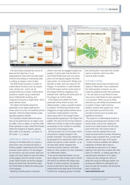
The Input Node indicates the source of<br />
data and the data flow. It is an<br />
organisational node which provides basic<br />
functions like adding or subtracting data,<br />
or setting up ranges or lists of data.<br />
The Math Node provides a number of<br />
mathematical functions such as square<br />
roots, division etc., which can be<br />
supplemented by complex mathematical<br />
equations created using a dedicated<br />
piece of Marionette scripting, and<br />
'wrapped' to become a single Node, with a<br />
newly defined name.<br />
The Object Info Nodes extract the<br />
parameters of an object (defining the<br />
centre point of a circle, for instance) and its<br />
diameter, whilst the Object Nodes create<br />
standard graphics objects.<br />
The Operation Nodes define the action<br />
that can be performed on an object, such<br />
as rotate, move or delete, or how the math<br />
Node operates on data, whilst Point Nodes<br />
define the locations of objects, placing<br />
them within a 2D drawing - x,y inputs, or<br />
3D model - x, y, z inputs.<br />
CREATING A SIMPLE POLYGON<br />
Clicking on the Marionette icon opens a<br />
drop-down menu showing the types of<br />
Nodes available. Selecting the Input folder<br />
provides further options. For the polygon<br />
we will need to use real number (real) and<br />
integer (int) Input Nodes to input the radius<br />
of the polygon and the number of sides.<br />
Under Object Nodes we find the polygon<br />
Node and select that. We will then need<br />
the Point2 Node to define the centre point<br />
of the polygon.<br />
Selecting a Node places it onscreen,<br />
where it can then be dragged roughly into<br />
position. It will be seen that the Real, Int<br />
and Point2 Nodes have only one output<br />
point, but the regular polygon has three<br />
input points - for centre point, Radius and<br />
Number of sides, and one output for the<br />
Polygon. A connection is made between<br />
the Point2 output and the centre point on<br />
the polygon Node by dragging a wire<br />
between both, defining the centre point of<br />
the polygon as it will be drawn.<br />
In the Object Info palette the Point2<br />
parameter will be shown as zero, the<br />
default position, unless a specific location<br />
is inserted. The Real Input Node is then<br />
dragged to an appropriate position and a<br />
connection made between it and the<br />
radius input point in the polygon Node -<br />
the parameter appearing in the Object Info<br />
palette. The same for the Int Input Node to<br />
define the number of sides of the polygon,<br />
connecting it to the number of numSides<br />
input point in the polygon node.<br />
All that remains is to run the script, which<br />
will produce a regular polygon in the<br />
position indicated. The script created can<br />
be grouped to be copied and used in other<br />
places throughout a wider network - or, as<br />
we have seen earlier, wrapped and<br />
renamed and then placed in the Node<br />
library for other projects (it is then classified<br />
as a Marionette object).<br />
If we use the data flow Nodes, we can<br />
input ranges or lists of data, each of which<br />
will need to be defined with single input<br />
Nodes. To avoid confusion, the specific<br />
source of each bit of input data can be<br />
entered above the type name of the Node.<br />
Furthermore, wrapping groups of Nodes<br />
and naming them cuts down the number<br />
used in a network, which can often<br />
become quite complex.<br />
THE MATH NODE<br />
Mathematics drives many functions and<br />
objects in Marionette. If you understand<br />
the math equation, however, you can<br />
create the graphical script that represents<br />
it. You will need an input Node for each<br />
value and a math Node for each operation<br />
in an equation. When you go to Node<br />
selection you will initially be presented with<br />
a number of basic math functions -<br />
addition, division and square root - but if<br />
you scroll down you will find more<br />
complex functions such as power and<br />
logarithmic functions.<br />
The script for a mathematical function is<br />
set up by processing each function in the<br />
correct order, one by one, feeding the<br />
result of one math function into the input<br />
point of the next. The correct order of<br />
function must be retained here or the<br />
values returned will be incorrect. Renaming<br />
Nodes is also important here, so that other<br />
users can follow the logic of the script.<br />
Further functions available with different<br />
categories of Nodes allow users to<br />
manipulate the geometry of an Object,<br />
aligning it with geometry created with other<br />
parts of a network, or rotating geometry, or<br />
specifying the orientation of an object.<br />
Users can also change the colour of<br />
Node fills using the Attributes palette, but<br />
as these are different to distinguish one<br />
class of code from another, one should be<br />
wary of doing this.<br />
www.vectorworks.com<br />
January/February 2017 13