The Logix 3000MD Series Digital Positioner - Flowserve Corporation
The Logix 3000MD Series Digital Positioner - Flowserve Corporation
The Logix 3000MD Series Digital Positioner - Flowserve Corporation

Create successful ePaper yourself
Turn your PDF publications into a flip-book with our unique Google optimized e-Paper software.
Experience In Motion<br />
TECHNICAL BULLETIN<br />
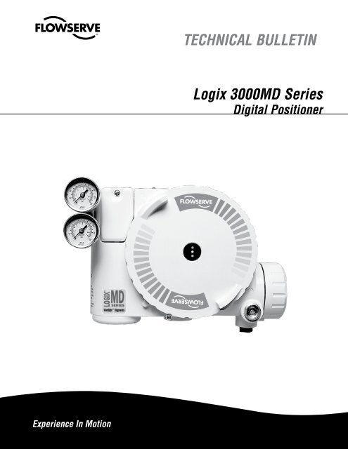
<strong>Logix</strong> <strong>3000MD</strong> <strong>Series</strong><br />
<strong>Digital</strong> <strong>Positioner</strong>
2<br />
Superior Performance and Reliability<br />
<strong>Logix</strong> <strong>3000MD</strong> <strong>Series</strong> <strong>Digital</strong> <strong>Positioner</strong> FCD LGENTB0059-03 – 01/11<br />
Introducing the <strong>Flowserve</strong> <strong>Logix</strong> <strong>3000MD</strong> <strong>Series</strong> <strong>Digital</strong> <strong>Positioner</strong><br />
<strong>The</strong> <strong>Flowserve</strong> ® <strong>Logix</strong> <strong>3000MD</strong> series high-performance digital positioners utilize state-of-the-art piezo technology to<br />
provide superior performance and reliability. This is accomplished through the use of a powerful 32-bit microprocessor<br />
and a proprietary two-stage electronic relay. Among the <strong>Logix</strong> <strong>3000MD</strong> series more attractive features are the on-board<br />
QUICK-CAL button, DIP switches, Jog buttons, and variable gain selector. <strong>The</strong>se features allow the user to complete setup<br />
and calibration of either diaphragm or piston operated valves in a couple of minutes, without the need of additional handheld<br />
devices or software.<br />
<strong>The</strong> <strong>Logix</strong> <strong>3000MD</strong> series positioners offer valve status updates at a glance using the highly visible LEDs. Users can easily<br />
determine if a valve or actuator is functioning properly, and quickly diagnose any problems using the smart LED blink codes.<br />
This means that maintenance personnel can provide a visual check of the valve status without having to remove the cover or<br />
connect a HART handheld device or maintenance PC/laptop.<br />
Predictive diagnostics is available using the ValveSight software available through FDT/DTM technology. ValveSight is a<br />
diagnostic solution for control valves that can be seamlessly integrated into most host control and/or plant asset management<br />
systems. <strong>The</strong> power of ValveSight is in the intelligent diagnostic engine which is constantly monitoring the valve, actuator,<br />
positioner and control signal for patterns of behavior that may indicate a problem and provides actional advice proactively.<br />
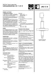
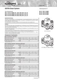
Inside the <strong>Logix</strong> 3200MD<br />
Figure 1 – <strong>Logix</strong> 3200MD Controls<br />
No Exposed<br />
Electronics<br />
All Blink<br />
Codes Listed<br />
Large QUICK-CAL<br />
Button<br />
Jog<br />
Buttons<br />
DIP Switches for<br />
Fast and Easy Setup<br />
Gain Selector<br />
Switch
<strong>Logix</strong> <strong>3000MD</strong> <strong>Series</strong> <strong>Digital</strong> <strong>Positioner</strong> FCD LGENTB0059-03 – 01/11<br />
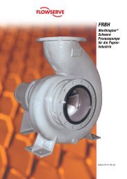
<strong>The</strong> <strong>Logix</strong> <strong>3000MD</strong> <strong>Series</strong> <strong>Digital</strong> <strong>Positioner</strong> - How It Works<br />
<strong>Logix</strong> <strong>3000MD</strong> <strong>Positioner</strong> Overview<br />
Figure 1: System Positioning Algorithm for <strong>Logix</strong> 3400MD<strong>Digital</strong> <strong>Positioner</strong>s<br />
<strong>Logix</strong> 3200MD<br />
4-20 MA<br />
(ANALOG<br />
MODE)<br />
Command In<br />
(<strong>Digital</strong> Mode)<br />
FOUNDATION<br />
Fieldbus<br />
Signal<br />
Command In<br />
(AO Block)<br />
Input<br />
Signal<br />
ANALOG<br />
DIGITAL<br />
OR<br />
FOUNDATION<br />
Fieldbus<br />
Transducer<br />
Block<br />
<strong>Logix</strong> 3400MD<br />
Tuning<br />
Linear Mode<br />
Characterization<br />
Soft Limits<br />
MPC<br />
CONTROL<br />
COMMAND<br />
Figure 1: <strong>Logix</strong> 3000 <strong>Series</strong><br />
<strong>Digital</strong> <strong>Positioner</strong>s Schematic<br />
(air-to-open configuration)<br />
+<br />
-<br />
Deviation<br />
O<br />
Stem<br />
Position<br />
Sensor<br />
Control<br />
Algorithm<br />
Pmax<br />
Pmin<br />
Gmult<br />
Integration<br />
Summer<br />
I<br />
Inner<br />
Loop<br />
Offset<br />
FF/HART<br />
Input Signal<br />
+<br />
+<br />
Exhaust<br />
Hall Effect<br />
Sensor<br />
Piezo Valve<br />
+<br />
Flame<br />
Arrestor<br />
Spool Valve<br />
Output 2<br />
D/A<br />
Output<br />
Percentage<br />
Output 1<br />
Inner-Loop<br />
Output<br />
Flame<br />
Arrestor<br />
+<br />
Air<br />
Supply<br />
-<br />
Pressure<br />
Sensor Board<br />
Air Supply<br />
Sensor<br />
Inner<br />
Loop<br />
Spool<br />
Control<br />
Piezo<br />
Valve<br />
Voltage<br />
Main PCB<br />
Flame<br />
Arrestor<br />
Filter<br />
Tubed<br />
ATO<br />
Stem<br />
Position<br />
Sensor<br />
<strong>Digital</strong> Position Algorithm<br />
Unlike other positioners that have only one set gains to set the response of the positioner, the <strong>Logix</strong> 3200MD positioner<br />
uses a multi-variable variable gain tuning algorithm. This allows the positioner to make large step changes with minimal<br />
overshoot, while achieving the resolution to respond to very small step changes.<br />
<strong>The</strong> Auto Tune procedure cycles the actuator to produce a measured response and selects those gain values that provide<br />
appropriate actuator performance. <strong>The</strong> Auto Tune function includes a gain modifier selector that can be used to increase or<br />
decrease the calculated gain in order to achieve optimal performance.<br />
By setting the Auto Tune on/off DIP switch, the tuning mode can be changed from auto to manual. <strong>The</strong> <strong>Logix</strong> <strong>3000MD</strong> <strong>Series</strong><br />
positioners provide several preset gain settings with a locally adjustable gain set selector directly from the user interface on<br />
the positioner. If custom settings are desired, tuning sets can be modified with a handheld or ValveSight, to accomodate a<br />
wide range of actuator sizes and types.<br />
Regulator<br />
LED<br />
Display<br />
3
4<br />
<strong>Logix</strong> <strong>3000MD</strong> <strong>Series</strong> <strong>Digital</strong> <strong>Positioner</strong> FCD LGENTB0059-03 – 01/11<br />
<strong>The</strong> <strong>Logix</strong> 3400MD for Foundation Fieldbus Applications<br />
Complete local configuration, on any valve/actuator and local.<br />
FF Simulate – Run a control strategy without process<br />
FF Write Protect – Locks out unauthorized writes to NVRAM<br />
36 status and<br />
alert and messages<br />
displayed locally via<br />
three easy-to-read<br />
LEDs<br />
<strong>Logix</strong> 3400MD Features<br />
RFI/EMI Immunity P<br />
FISCO Compliant, User Interface P<br />
Polarity Insensitive UI (Potted UI) P<br />
AO Block (30mS) P<br />
PID Block (6 PID Equations) (90mS) P<br />
2 DI Block (20mS) P<br />
1 DO Block (30mS) P<br />
1 IS Block (50mS) P<br />
1 OS Block (50mS) P<br />
LAS (Link Master Device) P<br />
Auto Tune (<strong>Positioner</strong> Performance) P<br />
High Friction Stability P<br />
FF Code Download P<br />
Flash Ram (Local <strong>Positioner</strong> Embedded Code Upgrade) P<br />
Local Valve Signature Storage P<br />
Local Calibration and Setup (While in OOS) P<br />
24/7 Local Fault Monitoring P<br />
Local Adjustable Gain P<br />
Wizard/Method for On-line Commissioning P<br />
Foundation Fieldbus made easy.<br />
(In OOS) Calibrate stroke<br />
and adjust tuning without<br />
entering the Transducer Block<br />
—Updates the Block when<br />
complete.<br />
<strong>Logix</strong> 3400MD Features<br />
Local Jog Buttons to Adjust 100% Command Position<br />
(While in OOS)<br />
Linkable Position feedback (AO Read Back) P<br />
Four Response Curves (Linear, =%, QO, and Custom)<br />
Locally Activated, or Through FF<br />
Multiple View Objects in Transducer Block P<br />
Honeywell PKS Partner with FDM P<br />
Methods Setup Wizard P<br />
DTM Available P<br />
Yokogawa VIP Partner & PRM supported P<br />
Honeywell PKS Advantage Partner ¸<br />
<strong>Flowserve</strong> is a Honeywell Partner, with <strong>Flowserve</strong><br />
DTM support pending in the ExperionDCS Field Device<br />
Manager. Please contact your Honeywell representative<br />
for details.<br />
P<br />
P
<strong>The</strong> <strong>Logix</strong> 3200MD for HART Applications<br />
Complete local configuration, just like the <strong>Logix</strong> 3400MD, but HART protocol<br />
• Local status and alert messages<br />
• Tuning (Auto Tune function and manual adjustment)<br />
• Jog buttons to manually adjust 100% position<br />
• Easy-to-install 4-20 mA analog feedback card option<br />
Simple plug-in AO card, automatically zero and spans position feedback during Quick Cal<br />
<strong>Logix</strong> 3200MD Features<br />
RFI/EMI Immunity P<br />
Auto Tune (<strong>Positioner</strong> Performance) P<br />
High Friction Stability Tuning P<br />
Integral 4-20 mA Feedback Option P<br />
Flash RAM (Local <strong>Positioner</strong> Embedded Code<br />
Upgrade)<br />
P<br />
Local Valve Signature Storage P<br />
Local Calibration and Setup P<br />
24/7 Local Fault Monitoring P<br />
Local Adjustable Gain P<br />
Three Response Curves (Linear, =% and custom) P<br />
Local Jog Buttons to Adjust 100% Command Position P<br />
Valve Signature Diag. “Valve Analysis” AMS<br />
SnapOn ® Application<br />
P<br />
AMS Device Manager P<br />
DTM Available P<br />
Yokogawa VIP Partner P<br />
Honeywell PKS Partner with Honeywell HART FDM P<br />
<strong>Logix</strong> <strong>3000MD</strong> <strong>Series</strong> <strong>Digital</strong> <strong>Positioner</strong> FCD LGENTB0059-03 – 01/11<br />
ValveSight Dashboard for <strong>Logix</strong> 3200MD or 3400MD<br />
Advanced DTM and Pro diagnostics<br />
5
6<br />
With the <strong>Logix</strong> 3400MD, function blocks are no longer<br />
required to set up, configure and perform a simple stroke<br />
calibration. <strong>The</strong> 3400MD can be set up with 9-32 VDC supply<br />
and 45 psi (min.) air supply on any valve/actuator platform.<br />
Calibration, configuration and tuning parameters from<br />
the local interface will be automatically updated in the<br />
Transducer Block on the <strong>Logix</strong> 3400MD. Local setup and<br />
calibration that does not require a link to a host controller,<br />
PC or hand-held device, as well as local validation that setup<br />
is correct, make any Foundation Fieldbus installation easy<br />
and straightforward.<br />
<strong>Logix</strong> <strong>3000MD</strong> <strong>Series</strong> <strong>Digital</strong> <strong>Positioner</strong> FCD LGENTB0059-03 – 01/11<br />
<strong>The</strong> <strong>Logix</strong> <strong>3000MD</strong> <strong>Series</strong> <strong>Positioner</strong>s – no software or handheld<br />
device required... easy as 1, 2, 3<br />
<strong>The</strong> <strong>Logix</strong> 3200MD can be set up with 10 VDC milliamp<br />
current supply current and 45 psi (min.) air supply on any<br />
valve/actuator platform.<br />
Calibration, configuration and tuning parameters from the<br />
local interface will be automatically updated in the HART<br />
registers on the <strong>Logix</strong> 3200MD. Local setup and calibration<br />
that does not require a link to a host controller, PC or handheld<br />
device, and local validation that setup is correct make<br />
any HART installation easy and straightforward.<br />
With the <strong>Logix</strong> 3200MD, the local interface shown to the<br />
right can be used to set up the unit in seconds through the<br />
When the 3400MD is in OOS (Out Of Service mode), the local following steps:<br />
GAIN<br />
interface shown to the right is accessible and setup can be<br />
H A B<br />
carried out through the following steps:<br />
G C<br />
Common Configuration Steps<br />
F D<br />
E<br />
1. Make sure the mechanical linkage, air tubing and actuator mounting are correct.<br />
2. Set the configuration switches to the desired operation of the valve/actuator.<br />
3. Set the quick calibration switch to Jog or Auto. In Jog, the 100% position can be manually adjusted using the yellow up<br />
and down buttons after Re-Cal is pressed. In Auto, the positioner finds the 100% position and calibration is complete. LED<br />
blink codes will guide the user through the process. Four green blinks (GGGG) or (GGGY) at the end of the sequence confirm<br />
that the calibration was successful.<br />
4. If needed, the GAIN switch located to the right of the jog buttons will speed up or slow down the positioner’s response to<br />
command changes. With the Auto Tune configuration switch set to “On”, the positioner’s algorithm will select a gain with no<br />
over-shoot. <strong>The</strong> ‘E” position of the rotary GAIN dial indicates “neutral” with respect to gain adjustment. Turning clockwise<br />
from E to H and will speed up the response. Tuning counter-clockwise from E will slow it down, with A being the slowest<br />
response.
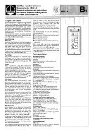
Time is Money<br />
3400<br />
• Three versions: Basic, Advanced (Advanced includes<br />
pressure sensors), and Pro (Pro includes pressure sensors<br />
and full featured valve diagnostics)<br />
• ITK - CFF 4.6, 5.0<br />
• DD available at www.fieldbus.org or www.flowserve.com<br />
• Stores a valve signature onboard in NVRAM<br />
• Linkable Position Feedback as part of the AO Function block.<br />
• Contains: AO, PID, 2-DI, DO, OS, IS function blocks.<br />
• Onboard temperature sensor to measure local positioner<br />
ambient<br />
• Stroke speed limiter (configurable in transducer block)<br />
• Stainless steel version available<br />
• DTM Available<br />
<strong>Logix</strong> <strong>3000MD</strong> <strong>Series</strong> <strong>Digital</strong> <strong>Positioner</strong> FCD LGENTB0059-03 – 01/11<br />
Shorter commissioning time gets you up and running, making money faster<br />
<strong>Logix</strong><br />
<strong>3000MD</strong><br />
<strong>Series</strong><br />
BONUS<br />
Plant commission schedule<br />
Other digital<br />
positioners<br />
Time to Startup and Commission<br />
<strong>3000MD</strong> <strong>Series</strong> Facts<br />
<strong>The</strong> local interface in the <strong>3000MD</strong> series positioners and the two way communication capability allows the user to quickly<br />
commission loops.<br />
3200<br />
• Three versions: Basic, Advanced (Advanced includes<br />
pressures), Pro (Pro includes pressure sensors and full<br />
featured valve diagnostics)<br />
• HART Command 1, 3, 9, 33 & 48<br />
• Burst Mode available to continuously transmit<br />
• Position command analog loop current<br />
• Final value of command after characterization<br />
• Supply pressure (advanced), Temperature (basic)<br />
• Stem position in percent<br />
• Onboard temperature sensor to measure local positioner<br />
ambient<br />
• Stroke speed limiter (configurable through HART)<br />
• Stainless steel version available<br />
• Enhanced Device Description for advanced signature<br />
diagnostics<br />
• Step test, friction test, HRL, data logger<br />
• DTM Available<br />
7
8<br />
<strong>Logix</strong> <strong>3000MD</strong> <strong>Series</strong> <strong>Digital</strong> <strong>Positioner</strong> FCD LGENTB0059-03 – 01/11<br />
<strong>The</strong>re’s a <strong>Flowserve</strong> Expert Inside - ValveSight FDT/DTM<br />
Technology<br />
<strong>Flowserve</strong>’s valvesight DtM soFtware helps Manage FielD Devices<br />
by coMbining the Features oF FielD network harDware anD the<br />
hart (3200MD) or FounDation FielDbus (3400MD) coMMunication<br />
protocols using FDt/DtM technology with the logix <strong>3000MD</strong> series<br />
positioners. valvesight is a coMplete soFtware package, Featuring a<br />
unique anD easy to unDerstanD health status oF the Device that shows<br />
not only probleMs, but the MagnituDe oF Developing probleMs as well.<br />
valvesight also has conFiguration anD calibration screens to Fully<br />
support the logix <strong>3000MD</strong> positioner FaMily. aDDitionally, the user<br />
can access custoMizeD reports For all conFiguration, calibration anD<br />
event Data. <strong>Flowserve</strong>’s valvesight DtM opens the ‘winDow’ to the<br />
Device anD allows iMMeDiate views with live FeeDback on all active<br />
Device sensors incluDing valve steM position, control signal, Friction,<br />
response tiMe anD other iMportant systeM Metrics.<br />
ValveSight DTM software enables communication between<br />
the software and field device networks using the HART<br />
or FF protocol and provides access to the 24/7 diagnostic<br />
information from field devices. Using FDT/DTM technology<br />
maintenance personnel can access any <strong>Logix</strong> <strong>3000MD</strong><br />
series positioner on the network from a single workstation.<br />
Additionally, the software has capability to store configuration<br />
and calibration history and view event logs for each digital<br />
positioner accessible through the network.<br />
DiagnosTic EnginE<br />
Users can now obtain a new level of detailed real time diagnostic<br />
information with ValveSight DTM software. ValveSight<br />
features an “Expert Inside’ performing real time on-line<br />
diagnostics 24 hours a day, 7 days a week. <strong>The</strong> diagnostic<br />
assessment of the ‘expert inside’ is instantly displayed on<br />
the local interface and through the ValveSight DTM software.<br />
<strong>The</strong> ‘health bars’ in the Dashboard view instantly indicate any<br />
developing issues and quickly direct the user to the implications<br />
and solutions for each problem. <strong>The</strong> system automatically<br />
prioritizes alarms to direct the user to the root cause.<br />
configuraTion ManagEMEnT<br />
ValveSight DTM software also allows the user to easily upload<br />
a configuration from the positioner. This means that a new<br />
replacement positioner can be identically configured with the<br />
simple click of a mouse once the correct configuration has<br />
been identified. ValveSight enables users to edit individual<br />
configurations and print a positioner configuration report.<br />
21-PoinT characTErizaTion curvE<br />
With ValveSight DTM software, the user can adjust a 21-point<br />
characterization curve to change the response of the positioner<br />
in order to meet the process requirements. <strong>The</strong> output<br />
of each control point is independent, allowing the user to<br />
create a custom curve with very high resolution. This customized<br />
curve can be saved in the memory of the <strong>Logix</strong> <strong>3000MD</strong><br />
positioners, and either activated or overridden with a simple<br />
on-board selector switch.<br />
signaTurEs<br />
<strong>The</strong> <strong>Logix</strong> <strong>3000MD</strong> positioners are designed to assure that<br />
data is easily gathered, stored and compared to historical<br />
valve data so the user can determine the performance of<br />
critical valves.<br />
With ValveSight DTM software a user-defined signature ramp<br />
or step response test can be generated with a <strong>Logix</strong> <strong>3000MD</strong><br />
positioner. Signatures can be saved and cataloged (and later<br />
retrieved) for comparison with a more recent signature.<br />
A special partial stroke signature function wil automatically<br />
test the valve/actuator and give a pass/fail indication.<br />
PosiTionEr PErforMancE<br />
Static performance and accuracy measures such as hysteresis,<br />
deadband, linearity, and repeatability can be obtained with the<br />
<strong>Logix</strong> <strong>3000MD</strong> positioners. <strong>The</strong>se values can be graphically<br />
depicted, stored and later retrieved for comparative analysis.
<strong>Logix</strong> <strong>3000MD</strong> <strong>Series</strong> <strong>Digital</strong> <strong>Positioner</strong> FCD LGENTB0059-03 – 01/11<br />
<strong>Logix</strong> <strong>3000MD</strong> <strong>Series</strong> Features List for ValveSight DTM<br />
oFF-line<br />
Foundation FieldBuS<br />
oVerView<br />
conFiguration<br />
caliBration<br />
on-line diagnoSticS<br />
diagnoSticS<br />
Function BlockS<br />
ValVeSight dtM logix 3200Md PoSitionerS logix 3400Md PoSitionerS<br />
ValVeSight<br />
BaSic<br />
ValVeSight<br />
adVanced<br />
Dashboard P 1 P P 1,3 P 1 P P 1,3 P 1 P<br />
All-Alarm Annunciator P P P 2,3 P 2 P P 2,3 P 2 P<br />
Configuration Management P P P P P P P P<br />
Local Interface Control P P P P P P P P<br />
Position Cutoff P P P P P P P P<br />
Soft Limits P P P P P P P P<br />
Custom Stroke Characterization P P P P P P P P<br />
Counters and Travel Settings P P P P P P P P<br />
Command Deviation Settings P P P P P P P P<br />
Custom Units of Measure P P P 3 P P P 3 P P<br />
All-Variable Editor P P P P P P P P<br />
logix<br />
3200Md<br />
logix<br />
3210Md<br />
logix<br />
3220Md<br />
Analog Output Calibration P P P P P<br />
Analog Input Calibration P P P P P<br />
Stroke Calibration P P P P P P P P<br />
Pressure and Friction Calibration P P P 2 P P 2 P<br />
Ramp Test P P P 3 P P P 3 P P<br />
Step Test P P P 3 P P P 3 P P<br />
HDRL Test P P P P P P P<br />
Data Logger P P 3 P P<br />
Supply Pressure P P P P P P 4<br />
Friction P P P<br />
Actuation Ratio P P P<br />
Pneumatic Leak P P P<br />
Long-Term Trends P P P<br />
Partial Stroke Test P P P<br />
Valve Health View P P P<br />
<strong>Positioner</strong> Health View P P P<br />
Actuator Health View P P P<br />
Control Health View P P P<br />
ao P P P<br />
Pid P P P<br />
do P P P<br />
di P P P<br />
oS P P P<br />
iS P P P<br />
1. Limited Function. No health information.<br />
2. Limited function. No friction or force monitoring.<br />
3. Limited function. No pressure monitoring or information.<br />
4. DCS Function<br />
logix<br />
3400Md<br />
logix<br />
3410Md<br />
logix<br />
3420Md<br />
9
10<br />
Specifications for <strong>Logix</strong> 3400MD<br />
Table I: Electrical Specifications<br />
Power Supply<br />
Two-wire, 9-32 VDC<br />
FF compatible<br />
IS Fisco compliant<br />
Communications FF Protocol ITK 4.6x, 5.0<br />
Operating Current 23 mA<br />
Maximum Voltage 36.0 VDC<br />
Table II: Environmental Conditions<br />
Operating Temperature<br />
Range<br />
Standard<br />
-40° to 176°F<br />
(-40° to 80°C)<br />
Transport and Storage<br />
Temperature Range<br />
-40° to 176°F (-40° to 80°C)<br />
Operating Humidity 0 - 100% non-condensing<br />
Note: <strong>The</strong> air supply must conform to ISA Standard ISA 7.0.01 (a<br />
dew point at least 18 degrees Fahrenheit below ambient temperature,<br />
particle size below five microns—one micron recommended—and<br />
oil content not to exceed one part per million).<br />
Table I: Electrical Specifications<br />
Power Supply<br />
Two-wire, 4-20 mA<br />
10.0 to 30.0 VDC<br />
Compliance Voltage 10.0 VDC @ 20 mA<br />
495 Ω @ 20 mA Typical<br />
Effective Resistance Add 20 Ω when HART communication<br />
active<br />
Communications HART Protocol ITK 5,6<br />
Minimum Operating 3.6 mA without AO board<br />
Current<br />
3.7 mA with AO board<br />
Maximum Voltage 30.0 VDC<br />
Table II: Environmental Conditions<br />
Operating Temperature<br />
Standard<br />
-4° to 176°F<br />
(-20° to 80°C)<br />
Range<br />
Low<br />
-40° to 176°F<br />
(-40° to 80°C)<br />
Transport and Storage<br />
Temperature Range<br />
-40° to 176°F (-40° to 80°C)<br />
Operating Humidity 0 - 100% non-condensing<br />
Note: <strong>The</strong> air supply must conform to ISA Standard ISA 7.0.01<br />
(a dew point at least 18 degrees Fahrenheit below ambient<br />
temperature, particle size below five microns—one micron recommended—and<br />
oil content not to exceed one part per million).<br />
<strong>Logix</strong> <strong>3000MD</strong> <strong>Series</strong> <strong>Digital</strong> <strong>Positioner</strong> FCD LGENTB0059-03 – 01/11<br />
<strong>The</strong> <strong>Logix</strong> <strong>3000MD</strong> <strong>Positioner</strong> Specifications<br />
Specifications for <strong>Logix</strong> 3200MD<br />
Table III: Physical Specifications<br />
Housing<br />
Material<br />
Cast, powder-painted aluminum or stainless steel<br />
Soft Goods Buna-N / Florosilicone<br />
Weight<br />
8.3 pounds (3.9 kg) aluminum<br />
20.5 pounds (9.3 kg) stainless steel<br />
Table IV: <strong>Positioner</strong> Specifications<br />
Deadband
<strong>The</strong> <strong>Logix</strong> <strong>3000MD</strong> E.O.M. Mounting Kits<br />
Brand Model Size Mounting Kit<br />
Fisher<br />
Neles<br />
Foxboro<br />
Honeywell<br />
Masoneilan (Linear Actuators)<br />
657 & 667<br />
1250<br />
30 213905<br />
34<br />
40<br />
50<br />
60<br />
141410<br />
171516<br />
0.5" – 1.5"<br />
stroke<br />
0.5" – 1.5"<br />
stroke<br />
171517 2" stroke<br />
171516<br />
0.5" – 1.5"<br />
stroke<br />
171517 2" stroke<br />
70 171518 4" stroke<br />
80 171519<br />
225<br />
450<br />
675<br />
173371<br />
1052 33 171549 Rotary<br />
657-8 40 173798<br />
RC 171512<br />
RD 178258<br />
Slid-Std 173567<br />
Linear 178258<br />
VST-VA3R 17-in. dia. 173798<br />
VSL-VA1D 12-in. dia. 173798<br />
37<br />
38<br />
71 Domotor<br />
88<br />
9<br />
11<br />
171721<br />
13 171720<br />
18 173382<br />
24 173896<br />
11 173235<br />
13 173234<br />
15 186070<br />
18 173382*<br />
24 173896<br />
25 173325<br />
50 173335<br />
100 173336<br />
6 171722<br />
16 173827<br />
47 B 173361<br />
48 B 173361<br />
“D”<br />
Domotor<br />
200 175141<br />
71-2057AB-D 176179<br />
71-40413BD 176251<br />
<strong>Logix</strong> <strong>3000MD</strong> <strong>Series</strong> <strong>Digital</strong> <strong>Positioner</strong> FCD LGENTB0059-03 – 01/11<br />
Brand Model Size Mounting Kit<br />
Masoneilan<br />
(Rotary<br />
Actuators)<br />
33 B 173298<br />
35<br />
6<br />
7<br />
173298<br />
70 10 173298<br />
0.75"<br />
Valtek Trooper 166636 – 1.50"<br />
Std<br />
Automax<br />
4<br />
R314 141180 HD<br />
SNA115 NK313A<br />
Vangard 37/64 175128<br />
Air-Torque AT <strong>Series</strong> AT0 – AT6<br />
SNA<br />
<strong>Series</strong><br />
SNA3 – SNA2000<br />
Automax<br />
N <strong>Series</strong> N250.300<br />
R <strong>Series</strong> R2 – R5<br />
Bettis<br />
RPC<br />
<strong>Series</strong><br />
G <strong>Series</strong><br />
RP – TPC11000<br />
G2009-M11<br />
– G3020-M11<br />
Consult factory<br />
EL-O- E <strong>Series</strong> E25 – E350<br />
Matic P <strong>Series</strong> P35 – P4000<br />
Hytork XL <strong>Series</strong> XL45 – XL4580<br />
Unitorq M <strong>Series</strong> M20 – M2958<br />
Worcester 39 <strong>Series</strong> 2539 - 4239<br />
*Adjustable mounting kit 173798 may be needed if handwheels<br />
are used.<br />
NAMUR Accessory Mounting Kit Part<br />
Numbers<br />
Bracket Option Description<br />
28 20 mm pinion x 80 mm bolt spacing<br />
28 38 mm pinion x 80 mm bolt spacing<br />
313 30 mm pinion x 80 mm bolt spacing<br />
513 50 mm pinion x 130 mm bolt spacing<br />
Bolt Option Description<br />
A 10-24 UNC bolting<br />
B 10-32 UNF bolting<br />
L M5-.8 metric bolting<br />
Example: NK313A, NAMUR Accessory Mounting Kit with 30 mm<br />
pinion x 80 mm bolt spacing and 10-24 UNC bolting.<br />
PlEasE conTacT your flowsErvE rEPrEsEnTaTivE for aDDi-<br />
Tional MounTing kiT availabiliTy.<br />
11
12<br />
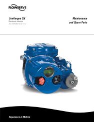
<strong>3000MD</strong> <strong>Series</strong> dimensions<br />
NOTE: Dimensions in inches (mm)<br />
Supply, Output 1 and<br />
Output 2 ports<br />
¼-18 NPT thread<br />
7.18<br />
(182.45)<br />
3.38<br />
(85.83)<br />
Follower arm limit<br />
is ±45° from position<br />
shown, maximum<br />
2.70<br />
(68.68)<br />
0.15<br />
(3.81)<br />
5.92<br />
(150.24)<br />
10.63<br />
(269.92)<br />
<strong>Logix</strong> <strong>3000MD</strong> <strong>Series</strong> <strong>Digital</strong> <strong>Positioner</strong> FCD LGENTB0059-03 – 01/11<br />
4.00<br />
(101.60)<br />
0.25<br />
(6.35)<br />
1.00<br />
(25.40)<br />
2.00<br />
(50.80)<br />
0.75<br />
(19.05)<br />
1.13<br />
(28.58)<br />
4.05<br />
(102.74)<br />
2.25<br />
(57.15)<br />
Square<br />
1.24<br />
(31.59)<br />
0.97<br />
(24.69)<br />
Customer conduit ports<br />
½-14 NPT thread<br />
(M20 optional)<br />
5.24<br />
(133.15)<br />
0.86<br />
(21.76)<br />
Driver Cover<br />
Spool Valve Cover and Vent<br />
LED Indicators<br />
Main Cover<br />
Customer<br />
Interface<br />
Cover
How to order<br />
Selection<br />
Protocol<br />
Diagnostics<br />
Material<br />
Design Version<br />
<strong>Logix</strong> <strong>3000MD</strong> <strong>Series</strong> <strong>Digital</strong> <strong>Positioner</strong> FCD LGENTB0059-03 – 01/11<br />
3200<br />
Code<br />
3400<br />
Code<br />
3 3<br />
4<br />
HART 2<br />
Foundation Fieldbus 4<br />
Standard (No Sensors) 0 0<br />
Advanced (With Sensors) 1 1<br />
Pro Diagnostics (with sensors and full ValveSight dianostics) 2 2<br />
Aluminum, White Paint (Valtek) 0 0<br />
Stainless Steel, No Paint (Valtek) 1 1<br />
Aluminum, Black Paint (Automax) 2 2<br />
Aluminum, Food-Grade White Paint (Automax) 3 3<br />
Aluminum, Black Paint (Accord) 4 4<br />
Aluminum, Food-Grade White Paint (Accord) 5 5<br />
Explosion Proof Class I, Div. 1, Groups B,C,D (FM) 01<br />
Intrinsically Safe Class I, Div. 1, Groups A,B,C,D (FM) 02<br />
INMETRO BR-EX ia IIC T4/T5; BR-Ex d IIB+H T5 (South America) 2 06 06<br />
Explosionproof Ex d IIB + H , Ex tD A21 T95 2<br />
Certifications<br />
0C, ATEX II 2 G (CENELEC)<br />
(GOST GGTN Ex d IIB+H ) 2<br />
Explosionproof Class I, Div 1, Groups B, C, D Intrinsically Safe Class I,<br />
07 07<br />
Div 1, Groups A through G (FM, CSA) FM Nonincendive. CSA Class I,<br />
Div 2, Class I, Zone 1, Group IIB + H and Exia Class 1, Zone 0,<br />
2<br />
Group IIC (CSA Only)<br />
10<br />
General Purpose<br />
Intrinsically Safe Ex ia IIC, T4 Tamb -40<br />
14 14<br />
0C to +850C, T5 Tamb -400C to +550C; Ex ia D 20,<br />
T950C -400C to +800C, ATEX II 1 G D (CENELEC) (GOST GGTN Ex i Intrinsically Safe IIC)<br />
15 15<br />
IECEx Explosionproof 16<br />
IECEx Intrinsically Safe<br />
ATEX:<br />
21 21<br />
Explosion Proof: II2G Ex d IIB+H T5; II2D Ex tD A21 T -40 2 amb 0C to +800C Intrinsically Save: II1G Ex ia IIC, T4 T -40 amb 0C to +850C, T5 T -40 amb 0C to +550C II1D Ex iaD 20 T950C -400C to + 800C Nonincendive: II3G Ex nL nA IIC, T4 T -40 amb 0C to +850C, T5 T -40 amb 0C to +550C II3D Ex tD A22 T950C -400C to + 800 D6 M<br />
C<br />
KOSHA*<br />
28<br />
Shaft<br />
DD 316 Stainless Steel Shaft (Valtek Standard)<br />
NAMUR 316 Stainless Steel (VDI/VDE 3845)<br />
D6<br />
N6<br />
D6<br />
N6<br />
Conduit<br />
1/2" NPT E E<br />
Connections M20 M M<br />
Four-way (Double-Acting) 04 04<br />
Action<br />
Three-way (Single-Acting)<br />
Four-way Vented (Double-Acting)<br />
03<br />
4V<br />
03<br />
4V<br />
Three-way Vented (Single-Acting) 3V 3V<br />
Temperature Low Temperature (-40°F to 176°F; -40°C to 80°C) 40 40<br />
SS with brass internals, psi (bar/kPa) (Valtek Standard) OG OG<br />
SS with SS internals, psi (bar/kPa) OS OS<br />
Gauges<br />
SS with brass internals, psi (kg/cm2 ) KG KG<br />
SS with SS internals, psi (kg/cm2 ) KS KS KS<br />
No Gauges 0U 0U<br />
No special options OO OO<br />
Special Options<br />
4-20 mA Position Feedback<br />
Remote Mount Feedback (Only Available with Certi cation Option 14)<br />
OF<br />
RM<br />
OF<br />
RM<br />
Fail Option Feedback* SF SF<br />
For each category, select the code for one of the options.<br />
* Contact factory before specifying this option<br />
Example<br />
3<br />
1<br />
0<br />
MD<br />
14<br />
4V<br />
40<br />
KS<br />
OF<br />
13
14<br />
<strong>Logix</strong> <strong>3000MD</strong> <strong>Series</strong> <strong>Digital</strong> <strong>Positioner</strong> FCD LGENTB0059-03 – 01/11<br />
<strong>Logix</strong> 3400MD Hazardous Area Certifications<br />
Notified Body Approval Temperature Code<br />
Enclosure<br />
Rating<br />
Explosionproof:<br />
Class I, Div 1, Groups B,C,D<br />
Dust Ignition Proof:<br />
Class II, III, Div 1, Groups E,F,G<br />
T6 T ≤= 60 amb 0 Intrinsically Safe:<br />
C Type 4/4X<br />
Class I, II, III, Div 1,<br />
Groups A,B,C,D,E,F,G<br />
Class 1, Zone 0, AEx ia IIC<br />
T4 T =-20 amb 0C to 60ºC TYPE 4X<br />
Non-Incendive:<br />
Class I, II, III, Div 2, Groups A,B,C,D,E,F,G T6 Tamb -200C to 600 Explosionproof:<br />
Class I, Div 1, Groups B,C,D<br />
C TYPE 4X<br />
Class II, Div 1, Groups E,F,G<br />
T5= -20<br />
Class III<br />
Ex d IIB+H2<br />
0 ≤ Ta ≤ +550C Type 4X<br />
Intrinsically Safe:<br />
Class I, II, III, Div 1, Groups A,B,C,D<br />
Class 1, Zone 0, Ex ia IIC<br />
T4 T -20 amb 0C to +600C Type 4X<br />
Explosionproof (Flameproof):<br />
II 2 GD<br />
Ex d IIB + H2 Ex tD A21 T95ºC<br />
T5 (T =-55ºC to +80ºC)<br />
Ta= -55<br />
ATEX<br />
0C to +550 Intrinsically Safe:<br />
C<br />
IP65<br />
II 1 G<br />
Ex ia IIC<br />
Non-Incendive:<br />
T4 (T -20ºC to + 60ºC) amb IP65<br />
II 3 G<br />
Ex nL nA IIC<br />
T6 T -20ºC to + 60ºC) amb IP65<br />
Explosionproof (Flameproof):<br />
1Ex d IIBT5/H X 2<br />
T5 (-50<br />
GOST GGTN<br />
0C ≤ Ta ≤ +550C) IP65<br />
Intrinsically Safe:<br />
0Ex ia IICT4X<br />
T4 (T -50 amb 0C to +600 Non-Incendive<br />
C) IP65<br />
2Ex nL IIC T6<br />
2Ex nA IIC T6<br />
T6= -500C to +800C IP65<br />
Explosionproof (Flameproof):<br />
BR-Ex d IIB + H2 T5=(-400 ≤ Ta ≤ +550C) IP65<br />
Intrinsically Safe:<br />
T4= (-20 0 ≤ Ta ≤ +600 ®<br />
C) IP65<br />
IECEx<br />
BR-Ex ia IIC<br />
Explosionproof:<br />
Ex d IIB+H2 Gb<br />
Ex tb IIIC T950C Db<br />
FMC 10.0032X - Pending<br />
Intrinsically Safe:<br />
Ex ia IIC T4 Ga<br />
T5 Ta= -55 0 to +80 0 C<br />
Ta= -55 0 C to +55 0 C<br />
IP65<br />
T4 (T amb -40 0 C to +60 0 C) IP65
<strong>Logix</strong> 3200MD Hazardous Area Certifications<br />
Notified Body Approval Temperature Code<br />
ATEX<br />
IECEx<br />
GOST<br />
KOSHA<br />
®<br />
Intrinsically Safe:<br />
Class I, II, III, Div 1, Groups A,B,C,D<br />
Class 1, Zone 0, AEx ia IIC<br />
Non-Incendive:<br />
Class I, Div 2, Groups A,B,C,D<br />
Explosionproof:<br />
Class I, Div 1, Groups B,C,D<br />
Dust Ignition Proof:<br />
Class II, III, Div 1, Groups E,F,G<br />
Explosionproof:<br />
Class I, Div 1, Groups B,C,D<br />
Class II, Div 1, Groups E,F,G<br />
Class III<br />
Ex d IIB+H2<br />
Intrinsically Safe:<br />
Class I, II, III, Div 1, Groups A,B,C,D<br />
Class II, E,F,G; Class III<br />
Non-Incendive:<br />
Class I, II, Div 2, Groups A,B,C,D<br />
Explosionproof (Flameproof):<br />
II 2 GD<br />
Ex d IIB + H2 Ex tD A21 T95ºC<br />
Intrinsically Safe:<br />
II 1 G D<br />
Ex ia IIC<br />
Ex iaD 20 T950C Non-Incendive:<br />
II 3 G<br />
Ex nL nA IIC<br />
Ex tD A22 T95 0 C<br />
Explosionproof (Flameproof):<br />
Ex d IIB + H2 Intrinsically Safe:<br />
Ex ia IIC<br />
Ex iaD 20 T950C Explosionproof (Flameproof):<br />
BR-Ex d IIB + H2 Intrinsically Safe:<br />
BR- Ex ia IIC<br />
Explosionproof (Flameproof):<br />
1Ex d IIBT5/H X 2<br />
Intrinisically Safe:<br />
0Ex ia IICT4X<br />
0Ex ia IICT5X<br />
Import Certificate<br />
Explosionproof (Flameproof):<br />
Ex d IIB + H2 <strong>Logix</strong> <strong>3000MD</strong> <strong>Series</strong> <strong>Digital</strong> <strong>Positioner</strong> FCD LGENTB0059-03 – 01/11<br />
T4 T amb ≤ = 85 0 C<br />
T5 T amb ≤ = 55 0 C<br />
T4 T amb ≤ = 85 0 C<br />
T5 T amb ≤ = 55 0 C<br />
Enclosure<br />
Rating<br />
NEMA 4X<br />
T6 T amb ≤ = 60ºC NEMA 4X<br />
T4 T amb -25º ≤ Ta ≤ +40ºC TYPE 4X<br />
T4 T amb ≤ = 85ºC<br />
T5 T amb ≤ = 55ºC<br />
T4 T amb ≤ = 85ºC<br />
T5 T amb ≤ = 55ºC<br />
Type 4X<br />
Type 4X<br />
T5 (T = -40ºC to + 80ºC) IP65<br />
T4 T amb -40ºC to + 85ºC<br />
T5 T amb -40ºC to + 55ºC<br />
T4 T -52ºC to + 85ºC<br />
amb<br />
T5 T -52ºC to + 55ºC<br />
amb<br />
Ex nL nA<br />
T4 T -40ºC to + 85ºC<br />
amb<br />
T5 T -40ºC to + 55ºC<br />
amb<br />
T4 T amb -52ºC to + 85ºC<br />
T5 T amb -52ºC to + 55ºC<br />
Ex tD T -40ºC to + 80ºC<br />
amb<br />
-52ºC to + 80ºC<br />
T5 (T -20ºC to + 55ºC)<br />
amb<br />
T5 (T -40ºC to + 55ºC)<br />
amb<br />
Ex ia<br />
T4 Ta = -40ºC to +85ºC<br />
T5 Ta = -400C to 550C Ex ia D<br />
Ta = -400 to +800C IP65<br />
IP65<br />
IP65<br />
IP65<br />
T5 (-40ºC ≤ Ta ≤ + 80ºC) IP65<br />
T5 (-40ºC ≤ Ta ≤ + 50ºC) IP65<br />
T5 T amb -20ºC to + 55ºC<br />
T5 T amb -40ºC to + 80ºC<br />
T4 T amb -50ºC to + 85ºC<br />
T5 T amb -50ºC to + 55ºC<br />
IP65<br />
IP65<br />
T5 (T = -40 0 C to +50 0 C) IP65<br />
15
FCD LGENTB0059-03 01/11 Printed in USA.<br />
To find your local <strong>Flowserve</strong> representative:<br />
For more information about <strong>Flowserve</strong> <strong>Corporation</strong>, visit<br />
www.flowserve.com or call USA 1 800 225 6989<br />
<strong>Flowserve</strong> <strong>Corporation</strong> has established industry leadership in the design and manufacture of its products. When properly selected, this <strong>Flowserve</strong> product is designed to perform its<br />
intended function safely during its useful life. However, the purchaser or user of <strong>Flowserve</strong> products should be aware that <strong>Flowserve</strong> products might be used in numerous applications<br />
under a wide variety of industrial service conditions. Although <strong>Flowserve</strong> can (and often does) provide general guidelines, it cannot provide specific data and warnings for all possible<br />
applications. <strong>The</strong> purchaser/user must therefore assume the ultimate responsibility for the proper sizing and selection, installation, operation, and maintenance of <strong>Flowserve</strong> products.<br />
<strong>The</strong> purchaser/user should read and understand the Installation Operation Maintenance (IOM) instructions included with the product, and train its employees and contractors in the safe<br />
use of <strong>Flowserve</strong> products in connection with the specific application.<br />
While the information and specifications contained in this literature are believed to be accurate, they are supplied for informative purposes only and should not be considered certified or<br />
as a guarantee of satisfactory results by reliance thereon. Nothing contained herein is to be construed as a warranty or guarantee, express or implied, regarding any matter with respect<br />
to this product. Because <strong>Flowserve</strong> is continually improving and upgrading its product design, the specifications, dimensions and information contained herein are subject to change<br />
without notice. Should any question arise concerning these provisions, the purchaser/user should contact <strong>Flowserve</strong> <strong>Corporation</strong> at any one of its worldwide operations or offices.<br />
© 2006 <strong>Flowserve</strong> <strong>Corporation</strong>, Irving, Texas, USA. <strong>Flowserve</strong> is a registered trademark of <strong>Flowserve</strong> <strong>Corporation</strong>.<br />
flowserve.com<br />
<strong>Flowserve</strong> Headquarters<br />
5215 N. O’Connor Blvd., Suite<br />
2300<br />
Irving, TX 75039<br />
Telephone: 972 443 6500<br />
Control Valve Manufacturing<br />
1350 Mountain Springs Parkway<br />
Springville, UT 84663-3004 USA<br />
Telephone: 1 801 489 8611<br />
Fax: 1 801 489 3719<br />
Singapore<br />
12 Tuas Ave. 20, 638824<br />
Republic of Singapore<br />
Telephone: +65 862 3332<br />
Fax: +65 862 4940<br />
Austria<br />
Kasernengasse 6<br />
Villach Austria 9500<br />
Telephone: +43 0 4242 41181 0<br />
Fax: +43 0 4242 41181 50<br />
Australia<br />
14 Dalmore Dr.<br />
Scoresby, Victoria, Australia 3179<br />
Telephone: +61 3 9759 3300<br />
Fax: +61 3 9759 3301<br />
China<br />
585, Hanwei Plaza<br />
7 Guanghua Road<br />
Beijing, China 100004<br />
Telephone: +86 10 6561 1900