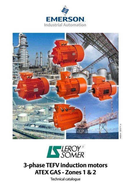
3-phase TEFV induction motors ATEX GAS - Zones 1 & 2
3-phase TEFV induction motors ATEX GAS - Zones 1 & 2
3-phase TEFV induction motors ATEX GAS - Zones 1 & 2

You also want an ePaper? Increase the reach of your titles
YUMPU automatically turns print PDFs into web optimized ePapers that Google loves.
3-<strong>phase</strong> <strong>TEFV</strong> <strong>induction</strong> <strong>motors</strong><br />
<strong>ATEX</strong> <strong>GAS</strong> - <strong>Zones</strong> 1 & 2<br />
Technical catalogue<br />
4428 en - 2010.11 / a
2<br />
A WORLDWIDE GROUP AT YOUR SERVICE<br />
With its 10,000-strong workforce, Leroy-Somer has created an<br />
international network of 470 centres of expertise and service centres<br />
capable of offering you the technical support you need, 24 hours a day,<br />
7 days a week throughout the world.<br />
To strengthen our commitment to the Oil and Chemicals market,<br />
Leroy-Somer has assembled a multidisciplinary team of highly<br />
qualified engineers to undertake global project management. Our<br />
R&D departments are directly involved in creating standard solutions<br />
dedicated to the new standards relating to potentially explosive<br />
atmospheres.
2<br />
3-<strong>phase</strong> <strong>TEFV</strong> <strong>induction</strong> <strong>motors</strong><br />
<strong>ATEX</strong> <strong>GAS</strong> - <strong>Zones</strong> 1 & 2<br />
4P<br />
1500 min -1 FLSD 100 L 3 kW<br />
3<br />
No. of poles<br />
Speed(s)<br />
Number and type<br />
of cable glands<br />
Series designation<br />
Frame size<br />
IEC 60072-1<br />
Description of<br />
cables<br />
Designation<br />
Housing<br />
designation<br />
II 2 G<br />
Ex d II B T4<br />
Rated output<br />
power<br />
1<br />
The complete motor reference described<br />
below will enable you to order the desired<br />
equipment.<br />
The selection method consists of following the<br />
terms in the designation.<br />
IM 1001<br />
IM B3<br />
Mounting<br />
arrangement<br />
IEC 60034-7<br />
230 /<br />
400 V<br />
Mains<br />
voltage<br />
50 Hz IP 55<br />
Mains<br />
frequency<br />
IEC 60034-5<br />
protection<br />
3
Zone 1: II 2 G Category 2<br />
4<br />
Other versions can also<br />
be selected:<br />
Ex d II B T5<br />
Ex d II C T5<br />
3-<strong>phase</strong> <strong>TEFV</strong> <strong>induction</strong> <strong>motors</strong><br />
<strong>ATEX</strong> <strong>GAS</strong> - <strong>Zones</strong> 1 & 2<br />
Example of marking:<br />
Distinctive community<br />
mark<br />
Symbol for equipment<br />
designed to comply with<br />
European standards<br />
Symbol specifying<br />
the protection type<br />
Explosion group<br />
Gas subdivision<br />
Temperature class<br />
EC type-examination<br />
certificate number<br />
Versions also available with type "e" terminal box.<br />
Other versions can also be selected:<br />
Ex e II T3 VIK<br />
Ex e II T4<br />
FLSD<br />
Cast iron frame<br />
0.18 to 400 kW<br />
Ex d (or de) II B T4 - Ex d (or de) II C T4<br />
Flameproof <strong>induction</strong> <strong>motors</strong><br />
{<br />
EN 60079-0<br />
Complies with EN 60079-1<br />
EN 60079-7<br />
(F)LSE<br />
Cast iron or aluminium frame<br />
0.75 to 55 kW<br />
Ex e II T3<br />
Increased safety <strong>induction</strong> <strong>motors</strong><br />
EN 60079-0<br />
Complies with {<br />
EN 60079-7<br />
Ex<br />
d II B T4 INERIS 01 <strong>ATEX</strong> 0001X
Zone 2: II 3 G Category 3<br />
An nA II T3 VIK version is also available<br />
Gas and Dust dual environment<br />
3-<strong>phase</strong> <strong>TEFV</strong> <strong>induction</strong> <strong>motors</strong><br />
<strong>ATEX</strong> <strong>GAS</strong> - <strong>Zones</strong> 1 & 2<br />
(F)LSN<br />
Cast iron or aluminium frame<br />
0.37 to 675 kW<br />
Ex nA II T3<br />
Non-sparking <strong>induction</strong> <strong>motors</strong><br />
EN 60079-0<br />
Complies with {<br />
EN 60079-15<br />
EN 60079-0/EN 60079-1/EN 60079-7/EN 60079-15<br />
Complies with { EN 61241-0/EN 61241-1<br />
Zone 1 + 21: II 2 GD Dual marking<br />
FLSD Ex d (or de) IIB T4 Ex tD A21 IP65 T125°C<br />
FLSD Ex d (or de) IIB T5 Ex tD A21 IP65 T100°C<br />
(F)LSE Ex e II T3 Ex tD A21 IP65 T125°C<br />
Zone 2 + 22: II 3 GD Dual marking<br />
(F)LSN Ex nA II T3 Ex tD A22 IP55 T125°C<br />
5
6<br />
- GENERAL INFORMATION<br />
3-<strong>phase</strong> <strong>TEFV</strong> <strong>induction</strong> <strong>motors</strong><br />
<strong>ATEX</strong> <strong>GAS</strong> - <strong>Zones</strong> 1 & 2<br />
PAGE<br />
Quality assurance ................................................................ 9<br />
General standardization ................................................... 10<br />
Tolerance on main performance parameters .................. 12<br />
Definition of atmospheres and zones ............................. 13<br />
Atmospheres at risk of explosion ........................................ 13<br />
Definition of hazardous areas ............................................. 13<br />
Explosion group classification ............................................. 13<br />
Temperature classes........................................................... 13<br />
Classification of common gases (indicative values) ..... 14<br />
Definition of equipment .................................................... 15<br />
Types of protection.............................................................. 15<br />
Comparison of USA/European standards ........................... 15<br />
Installation rules for surface industries .......................... 16<br />
Regulation relating to zones at risk of explosion caused<br />
by gas and vapours ............................................................. 16<br />
Choice of equipment depending on the zone ...................... 16<br />
Installation technologies ..................................................... 16<br />
Conditions of use .............................................................. 17<br />
Normal operating conditions ............................................... 17<br />
Motor used with frequency inverter ..................................... 17<br />
Power correction ................................................................. 17<br />
Severe environment............................................................ 17<br />
V.I.K. version for German heavy industry ............................ 17<br />
- ENVIRONMENT<br />
Definition of “Index of Protection” (IP/IK) ........................ 18<br />
Heaters .............................................................................. 19<br />
Space heaters..................................................................... 19<br />
D.C. injection ...................................................................... 19<br />
A.C. injection....................................................................... 19<br />
External finish ................................................................... 20<br />
Contents<br />
Copyright 2010: MOTEURS LEROY-SOMER<br />
- CONSTRUCTION<br />
PAGE<br />
Description of FLSD flameproof <strong>motors</strong>: Ex d II B T4 ..... 21<br />
Other descriptions of FLSD flameproof <strong>motors</strong> ............. 22<br />
Variants: FLSD cast iron <strong>motors</strong> with increased safety<br />
terminal box Ex d e IIB ........................................................ 22<br />
FLSD cast iron <strong>motors</strong> in version Ex d IIC and Ex d e IIC .... 22<br />
Description of (F)LSE increased safety <strong>motors</strong>:<br />
Ex "e" and (F)LSN non-sparking <strong>motors</strong>: Ex "nA" ......... 23<br />
Mounting arrangements ................................................... 24<br />
Bearings and lubrication .................................................. 25<br />
Lubrication of bearings........................................................ 25<br />
Grease life .......................................................................... 27<br />
Standard bearing fitting arrangements ................................ 27<br />
Axial load of FLSD <strong>motors</strong> ............................................... 28<br />
Permissible axial load (in daN) on main shaft<br />
extension for standard bearing assembly<br />
in FLSD flameproof <strong>motors</strong> ................................................. 28<br />
Axial load of LSE/LSN <strong>motors</strong> .......................................... 31<br />
Permissible axial load (in daN) on main<br />
shaft extension for standard bearing assembly<br />
in LSE/LSN increased safety and non-sparking<br />
<strong>motors</strong> with aluminium frame .............................................. 31<br />
Axial load of FLSE/FLSN <strong>motors</strong> ..................................... 34<br />
Permissible axial load (in daN) on main<br />
shaft extension for standard bearing assembly<br />
in FLSE/FLSN increased safety and non-sparking<br />
<strong>motors</strong> with cast iron frame ................................................. 34<br />
Mains connection ............................................................. 37<br />
Positions of the terminal box and cable gland ..................... 37<br />
Power supply cables ........................................................... 38<br />
Number and type of adaptable cable glands on type “d”<br />
terminal box for FLSD flameproof <strong>motors</strong>............................ 38<br />
Type of adaptable cable glands on type “e” terminal box<br />
for FLSD flameproof - (F)LSE increased safety - (F)LSN<br />
non-sparking <strong>motors</strong> ........................................................... 38<br />
Power supply terminals - direction of rotation ...................... 39<br />
Wiring diagrams .................................................................. 39<br />
Earth terminals.................................................................... 39<br />
Leroy-Somer reserves the right to modify the characteristics of its products at any time in order to incorporate the latest technological developments.<br />
The information contained in this document may therefore be changed without notice.
- OPERATION<br />
3-<strong>phase</strong> <strong>TEFV</strong> <strong>induction</strong> <strong>motors</strong><br />
<strong>ATEX</strong> <strong>GAS</strong> - <strong>Zones</strong> 1 & 2<br />
PAGE<br />
Weighted sound level [dB(A)] ........................................... 40<br />
Motor vibration levels - Balancing ................................... 41<br />
- ELECTROMECHANICAL CHARACTERISTICS<br />
FLSD FLAMEPROOF - ZONE 1<br />
Selection data .................................................................... 44<br />
2 poles - 3000 min -1 ............................................................. 44<br />
4 poles - 1500 min -1 ............................................................. 45<br />
6 poles - 1000 min -1 ............................................................. 46<br />
8 poles - 750 min -1 .............................................................. 47<br />
Dimensions ....................................................................... 48<br />
Shaft extensions ................................................................. 48<br />
Foot mounted IM B3 (IM 1001)............................................ 49<br />
Foot and flange mounted IM B35 (IM 2001) ........................ 50<br />
Flange mounted IM B5 (IM 3001) IM V1 (IM 3011) .............. 51<br />
Foot and face mounted IM B34 (IM 2101) ........................... 52<br />
Face mounted IM B14 (IM 3601) ......................................... 53<br />
- ELECTROMECHANICAL CHARACTERISTICS<br />
FLSE INCREASED SAFETY - ZONE 1<br />
FLSN NON-SPARKING - ZONE 2<br />
Selection data for FLSE increased safety - zone 1 .......... 56<br />
2 poles - 3000 min-1 - Ex e II T3 ........................................... 56<br />
4 poles - 1500 min-1 - Ex e II T3 ........................................... 57<br />
6 poles - 1000 min-1 - Ex e II T3 ........................................... 58<br />
2 poles - 3000 min-1 - Ex e II T4 ........................................... 59<br />
4 poles - 1500 min-1 - Ex e II T4 ........................................... 60<br />
Selection data for FLSN non-sparking - zone 2 ............... 62<br />
2 poles - 3000 min-1 - Ex nA II T3 ......................................... 62<br />
4 poles - 1500 min-1 - Ex nA II T3 ......................................... 63<br />
6 poles - 1000 min-1 - Ex nA II T3 ......................................... 64<br />
8 poles - 750 min-1 - Ex nA II T3 .......................................... 65<br />
FLSE - FLSN dimensions .................................................. 66<br />
Shaft extensions ................................................................. 66<br />
Foot mounted IM B3 (IM 1001)............................................ 67<br />
Foot and flange mounted IM B35 (IM 2001) ........................ 68<br />
Flange mounted IM B5 (IM 3001) ........................................ 69<br />
Foot and face mounted IM B34 (IM 2101) ........................... 70<br />
Face mounted IM B14 (IM 3601) ......................................... 71<br />
Contents<br />
- ELECTROMECHANICAL CHARACTERISTICS<br />
LSE INCREASED SAFETY - ZONE 1<br />
LSN NON-SPARKING - ZONE 2<br />
PAGE<br />
Selection data for LSE increased safety - zone 1 ............ 74<br />
2 poles - 3000 min-1 - Ex e II T3 ........................................... 74<br />
4 poles - 1500 min-1 - Ex e II T3 ........................................... 75<br />
6 poles - 1000 min-1 - Ex e II T3 ........................................... 76<br />
2 poles - 3000 min-1 - Ex e II T4 ........................................... 77<br />
4 poles - 1500 min-1 - Ex e II T4 ........................................... 78<br />
Selection data for LSN non-sparking - zone 2 ................. 80<br />
2 poles - 3000 min-1 - Ex nA II T3 ......................................... 80<br />
4 poles - 1500 min-1 - Ex nA II T3 ......................................... 81<br />
6 poles - 1000 min-1 - Ex nA II T3 ......................................... 82<br />
8 poles - 750 min-1 - Ex nA II T3 .......................................... 83<br />
LSE - LSN dimensions ....................................................... 84<br />
Shaft extensions ................................................................. 84<br />
Foot mounted IM B3 (IM 1001)............................................ 85<br />
Foot and flange mounted IM B35 (IM 2001) ........................ 86<br />
Flange mounted IM B5 (IM 3001) ........................................ 87<br />
Foot and face mounted IM B34 (IM 2101) ........................... 88<br />
Face mounted IM B14 (IM 3601) ......................................... 89<br />
- OPTIONAL FEATURES<br />
Electrical options .............................................................. 90<br />
Thermal protection .............................................................. 90<br />
Mechanical options .......................................................... 91<br />
Terminal box ....................................................................... 91<br />
Adaptation for vibration sensor ........................................... 92<br />
Draining of condensation .................................................... 92<br />
Tapped holes for positioning ............................................... 92<br />
Radial seal .......................................................................... 92<br />
Forced ventilation ............................................................... 93<br />
Encoders ............................................................................ 93<br />
Roller bearings.................................................................... 93<br />
Flying leads......................................................................... 93<br />
Non-standard flanges ......................................................... 94<br />
Drip cover ........................................................................... 97<br />
7
8<br />
3-<strong>phase</strong> <strong>TEFV</strong> <strong>induction</strong> <strong>motors</strong><br />
<strong>ATEX</strong> <strong>GAS</strong> - <strong>Zones</strong> 1 & 2<br />
PAGE<br />
Altitude .............................................................................. 17<br />
Ambient temperature ......................................................... 17<br />
Auxiliary terminal box ......................................................... 91<br />
Balancing...................................................................... 41-42<br />
Bearings ............................................................................ 26<br />
Cable glands ...................................................................... 38<br />
Cables ............................................................................... 38<br />
Certification.......................................................................... 9<br />
Condensation .................................................................... 92<br />
Connection ........................................................................ 37<br />
Connection ........................................................................ 39<br />
Degree of protection .......................................................... 18<br />
Dimensions .................................... 48 to 53-66 to 71-84 to 89<br />
Direction of rotation ............................................................ 39<br />
Drip cover .......................................................................... 97<br />
Earth terminals................................................................... 39<br />
Earthing ............................................................................. 39<br />
Electrical and mechanical characteristics ................. 43 to 89<br />
Encoder ............................................................................. 93<br />
Environment ...................................................................... 17<br />
Explosion groups ............................................................... 14<br />
Fan cover .................................................................. 21 to 23<br />
Flameproof casing ........................................................ 15-21<br />
Flanges ..................................................................... 94 to 96<br />
Flying leads........................................................................ 93<br />
Forced ventilation .............................................................. 93<br />
Frequency control .............................................................. 17<br />
Gas .................................................................................... 14<br />
Greasing ............................................................................ 26<br />
Identification ........................................................................ 3<br />
Ignition temperature ...................................................... 13-14<br />
Increased safety ..................................................... 15-22-23<br />
Lifting rings ................................................................... 21-23<br />
Lubrication .................................................................... 25-26<br />
Marking ............................................................................. 4-5<br />
Mounting arrangements ..................................................... 24<br />
NEC ................................................................................... 15<br />
NEMA ................................................................................ 15<br />
Noise ................................................................................. 40<br />
Official accreditation laboratories ......................................... 9<br />
Operating positions ............................................................ 24<br />
Index<br />
PAGE<br />
Paint .................................................................................. 20<br />
Permissible axial load ............................................... 28 to 36<br />
Potentially explosive atmospheres..................................... 13<br />
Quality assurance ................................................................ 9<br />
Responsibility of the person carrying out the work ............. 16<br />
Space heaters.................................................................... 19<br />
Standards ..................................................................... 10-11<br />
Surface temperature .......................................................... 13<br />
Tapped holes for positioning .............................................. 92<br />
Terminal blocks .................................................................. 39<br />
Terminal box ........................................................ 21 to 23-37<br />
Thermal protection ............................................................. 90<br />
Tolerances ......................................................................... 12<br />
Types of protection............................................................. 15<br />
Variable speed ................................................................... 17<br />
Vibration ....................................................................... 41-42<br />
Vibration sensor ................................................................. 92<br />
VIK ..................................................................................... 17<br />
<strong>Zones</strong>............................................................................ 13-16
LEROY-SOMER's quality management<br />
system is based on:<br />
- Control of procedures right from the initial<br />
sales offering until delivery to the customer,<br />
including design, manufacturing start-up and<br />
production<br />
- A total quality policy based on making<br />
continuous progress in improving operational<br />
procedures, involving all departments in<br />
the company in order to give customer<br />
LEROY-SOMER has entrusted the<br />
certification of its expertise to various<br />
international organisations.<br />
Certification is granted by independent<br />
professional auditors, and recognises the<br />
high standards of the company's quality<br />
assurance procedures.<br />
All activities resulting in the final version<br />
of the machine have therefore received<br />
official certification ISO 9001: 2000 from<br />
the DNV.<br />
Similarly, our environmental approach<br />
has enabled us to obtain certification ISO<br />
14001: 2004.<br />
Products for particular applications or<br />
those designed to operate in specific<br />
environments are also approved or<br />
certified by the following organisations:<br />
INERIS, LCIE, DNV, BSRIA, TUV, CCC,<br />
GOST, which check their technical<br />
performance against the various standards<br />
or recommendations.<br />
CERTIFICATION<br />
The <strong>ATEX</strong> <strong>motors</strong> presented in this catalogue<br />
comply with the national and/or international<br />
standards governing the construction of this<br />
type of equipment.<br />
EC type-examination certificates are drawn<br />
up by notified bodies, in accordance with the<br />
European Community Council Directive<br />
94/9/EC known as <strong>ATEX</strong>.<br />
Approval is obtained when descriptive<br />
documents have been examined and<br />
validated, and tests performed. These include<br />
tests involving heating and explosion of the<br />
equipment.<br />
EC-type examination certificates granted by<br />
the bodies listed opposite are recognized by<br />
all EC countries.<br />
Approved equipment is authorized to carry<br />
the CE mark or the distinctive community<br />
mark<br />
3-<strong>phase</strong> <strong>TEFV</strong> <strong>induction</strong> <strong>motors</strong><br />
<strong>ATEX</strong> <strong>GAS</strong> - <strong>Zones</strong> 1 & 2<br />
General information<br />
A1 - Quality assurance<br />
satisfaction as regards delivery times,<br />
conformity and cost<br />
- Indicators used to monitor procedure<br />
performance.<br />
- Corrective actions and advancements<br />
with tools such as FMECA, QFD, MAVP,<br />
MSP/MSQ and Hoshin type improvement<br />
workshops on flows, process re-engineering,<br />
plus Lean Manufacturing and Lean Office.<br />
- Annual surveys, opinion polls and regular<br />
visits to customers in order to ascertain and<br />
detect their expectations.<br />
Personnel are trained and take part in the<br />
analyses and actions for continuously<br />
improving the procedures.<br />
ISO 9001 : 2000<br />
9
10<br />
3-<strong>phase</strong> <strong>TEFV</strong> <strong>induction</strong> <strong>motors</strong><br />
<strong>ATEX</strong> <strong>GAS</strong> - <strong>Zones</strong> 1 & 2<br />
General information<br />
ORGANIZATION OF STANDARDS AUTHORITIES<br />
International bodies<br />
Worldwide<br />
A2 - General standardization<br />
TC<br />
Committees<br />
technical<br />
General<br />
standardization<br />
ISO<br />
International Standards<br />
Organisation<br />
SC<br />
Subcommittees<br />
European CEN<br />
European Committee<br />
for Standards<br />
ECISS<br />
European Committee for<br />
Iron and Steel Standardization<br />
TC<br />
Technical committees<br />
WG<br />
Working<br />
groups<br />
Electronics/electrotechnical<br />
standardization<br />
IEC<br />
International Electrotechnical<br />
Commission<br />
TC<br />
Committees<br />
technical<br />
SC<br />
Subcommittees<br />
CENELEC<br />
WG<br />
Working<br />
groups<br />
European Committee for Electrotechnical<br />
Standardization<br />
TC<br />
Technical<br />
committees<br />
SC<br />
Subcommittees<br />
AHG<br />
Ad hoc<br />
groups
List of standards quoted in this document<br />
3-<strong>phase</strong> <strong>TEFV</strong> <strong>induction</strong> <strong>motors</strong><br />
<strong>ATEX</strong> <strong>GAS</strong> - <strong>Zones</strong> 1 & 2<br />
General information<br />
References International standards<br />
IEC/EN 60034-1 Electrical rotating machines: ratings and operating characteristics.<br />
IEC/EN 60034-5 Electrical rotating machines: classification of degrees of protection provided by casings of rotating machines.<br />
IEC/EN 60034-6 Electrical rotating machines (except traction): cooling methods.<br />
IEC/EN 60034-7 Electrical rotating machines (except traction): symbols for mounting positions and assembly layouts.<br />
IEC 60034-8 Electrical rotating machines: terminal markings and direction of rotation.<br />
IEC/EN 60034-9 Electrical rotating machines: noise limits.<br />
IEC/EN 60034-12 Starting characteristics for single-speed three-<strong>phase</strong> cage <strong>induction</strong> <strong>motors</strong> for supply voltages less than or equal to 660 V.<br />
IEC/EN 60034-14<br />
IEC 60034-2<br />
Electrical rotating machines: mechanical vibrations of certain machines with a frame size above or equal to 56 mm.<br />
Measurement, evaluation and limits of vibrational intensity.<br />
Electrical rotating machines: methods for determining losses and efficiency from tests (additional losses added as a fixed<br />
percentage).<br />
IEC 60034-2-1 Electrical rotating machines: methods for determining losses and efficiency from tests (measured additional losses).<br />
IEC 60034-30<br />
IEC 60038 IEC standard voltages.<br />
IEC 60072-1<br />
Electrical rotating machines: efficiency classes for single-speed three-<strong>phase</strong> cage <strong>induction</strong> <strong>motors</strong><br />
(IE code).<br />
Dimensions and power series for electrical rotating machines: designation of casings between 56 and 400 and flanges<br />
between 55 and 1080.<br />
IEC 60085 Evaluation and thermal classification of electrical insulation.<br />
IEC/EN 60529 Degrees of protection provided by enclosures.<br />
IEC 60721-2-1 Classification of natural environment conditions. Temperature and humidity.<br />
IEC 60892 Effects of an imbalance in the voltage system on the characteristics of three-<strong>phase</strong> squirrel-cage <strong>induction</strong> <strong>motors</strong>.<br />
IEC/EN 61000-2-2 Electromagnetic compatibility (EMC): environment.<br />
IEC guide 106 Guidelines on the specification of environmental conditions for the determination of operating characteristics of equipment.<br />
ISO 281 Bearings - Basic dynamic loadings and nominal bearing life.<br />
ISO/EN ISO 1680<br />
Acoustics - Test code for measuring airborne noise emitted by electrical rotating machines: a method for establishing an expert<br />
opinion for free field conditions over a reflective surface.<br />
ISO 8821 Mechanical vibration - Balancing. Conventions on shaft keys and related parts.<br />
EN 60529 Degree of protection provided by electrical enclosures against extreme mechanical impacts.<br />
New Ref. Old Ref.<br />
EN 60079-0 EN 50014 Electrical equipment for explosive atmospheres: general regulations.<br />
EN 60079-1 EN 50018 Electrical equipment for explosive atmospheres: "d" flameproof casings.<br />
EN 60079-7 EN 50019 Electrical equipment for potentially explosive atmospheres: "e" increased safety.<br />
EN 60079-14 Electrical installations in hazardous areas.<br />
A2 - General standardization<br />
EN 60079-15 EN 50021 Electrical equipment for explosive atmospheres: "n" non-sparking.<br />
EN 61241-0 & 1 EN 50281-1-1 Electrical apparatus for use in the presence of combustible dust.<br />
11
12<br />
3-<strong>phase</strong> <strong>TEFV</strong> <strong>induction</strong> <strong>motors</strong><br />
<strong>ATEX</strong> <strong>GAS</strong> - <strong>Zones</strong> 1 & 2<br />
General information<br />
Tolerances on electromechanical characteristics<br />
IEC 60034-1 specifies standard tolerances for electromechanical characteristics.<br />
Parameters Tolerances<br />
Efficiency machines P ≤ 150 kW<br />
{ machines P > 150 kW<br />
– 15% (1 – η)<br />
– 10% (1 – η)<br />
Cos ϕ – 1/6 (1 – cos ϕ)<br />
(min 0.02 - max 0.07)<br />
Slip machines P < 1 kW<br />
{ machines P ≥ 1 kW<br />
± 30%<br />
± 20%<br />
Locked rotor torque – 15%, + 25% of rated torque<br />
Starting current + 20%<br />
Run-up torque – 15% of rated torque<br />
Maximum torque – 10% of rated torque<br />
> 1.6 MN Moment of inertia ± 10%<br />
Noise + 3 dB (A)<br />
Vibration + 10% of the guaranteed class<br />
Note: - IEC 60034-1 does not specify tolerances for current<br />
- the tolerance is ± 10% in NEMA-MG1<br />
Tolerances and adjustments<br />
The standard tolerances shown below are applicable to the mechanical characteristics given in<br />
our catalogues. They comply fully with the requirements of IEC standard 60072-1.<br />
Characteristics Tolerances<br />
Frame size H ≤ 250<br />
≥ 280<br />
Diameter ∅ of the shaft extension:<br />
- 11 to 28 mm<br />
- 32 to 48 mm<br />
- 55 mm and over<br />
0, — 0.5 mm<br />
0, — 1 mm<br />
Diameter N of flange spigots j6 up to FF 500,<br />
js6 for FF 600 and over<br />
Key width h9<br />
Width of drive shaft keyway<br />
(normal keying)<br />
N9<br />
Key depth:<br />
- square section<br />
- rectangular section<br />
A3 - Tolerance on main performance parameters<br />
jEccentricity of shaft in flanged <strong>motors</strong><br />
flanged (standard class)<br />
- diameter > 10 up to 18 mm<br />
- diameter > 18 up to 30 mm<br />
- diameter > 30 up to 50 mm<br />
- diameter > 50 up to 80 mm<br />
- diameter > 80 up to 120 mm<br />
kConcentricity of spigot diameter and<br />
lperpendicularity of mating surface of flange in relation to shaft<br />
(standard class)<br />
Flange (FF) or Faceplate (FT):<br />
- F 55 to F 115<br />
- F 130 to F 265<br />
- FF 300 to FF 500<br />
- FF 600 to FF 740<br />
- FF 940 to FF 1080<br />
j6<br />
k6<br />
m6<br />
h9<br />
h11<br />
0.035 mm<br />
0.040 mm<br />
0.050 mm<br />
0.060 mm<br />
0.070 mm<br />
0.08 mm<br />
0.10 mm<br />
0.125 mm<br />
0.16 mm<br />
0.20 mm<br />
E/2<br />
j Eccentricity of shaft in flanged <strong>motors</strong><br />
k Concentricity of spigot diameter<br />
10<br />
l Perpendicularity of mating surface of<br />
flange in relation to shaft<br />
10
A4.1 - ATMOSPHERES AT RISK<br />
OF EXPLOSION<br />
This includes all explosive and potentially<br />
explosive conditions, the explosion character<br />
being permanent or potential.<br />
Explosive atmospheres:<br />
An explosive atmosphere is an atmosphere<br />
containing a mixture of air and inflammable<br />
substances (in the form of gas, vapour, fog<br />
or mist) in such proportions that<br />
excessive temperature, arcs or sparks cause<br />
it to explode. The danger is permanent.<br />
Potentially explosive atmospheres:<br />
A potentially explosive atmosphere is an<br />
atmosphere which may become explosive<br />
due to the particular local conditions. The<br />
danger is potential.<br />
A4.3 - EXPLOSION GROUP<br />
CLASSIFICATION<br />
A4.3.1 - Area levels<br />
The areas presenting explosion risks are<br />
divided into 2 groups:<br />
- Group I: Gas-prone mines.<br />
- Group II: Areas other than gas-prone<br />
mines (surface industries).<br />
This catalogue only concerns equipment<br />
in group II.<br />
A4.4 - TEMPERATURE CLASSES<br />
A4.4.1 - Definition of temperature<br />
classes according to IEC 60079-0<br />
The temperature class is based on the<br />
maximum temperature rise in the equipment<br />
and on the ambient operating temperature.<br />
The maximum surface temperature of an<br />
electrical appliance must always be lower<br />
than the ignition temperature of the mix of<br />
gases or vapour in which it will be used.<br />
A4.4.2 - Definition of temperature<br />
classes according to IEC 60079-7 for<br />
Ex e<br />
- T°c = temperature<br />
- DT at PN = temperature at rated power<br />
- tS = time<br />
- tE = locked rotor time<br />
- A = temperature rise in normal duty<br />
- B<br />
= temperature rise during locked rotor test<br />
In the event of rotor failure and locking, an<br />
actuator must be able to disconnect the motor<br />
from the supply in a period t < tE .<br />
3-<strong>phase</strong> <strong>TEFV</strong> <strong>induction</strong> <strong>motors</strong><br />
<strong>ATEX</strong> <strong>GAS</strong> - <strong>Zones</strong> 1 & 2<br />
General information<br />
A4 - Definition of atmospheres and zones<br />
A4.2 - DEFINITION OF ZONES AT<br />
RISK OF EXPLOSION<br />
The international standard EN 60079-10<br />
defines the danger zones according to the<br />
risk of encountering an explosive atmosphere<br />
as shown in the diagram opposite:<br />
Zone 0: location where an explosive<br />
gaseous atmosphere is permanently<br />
present for long periods.<br />
Zone 1: location where an explosive<br />
gaseous atmosphere is likely to develop<br />
during normal operation.<br />
Zone 2: location where an explosive<br />
gaseous atmosphere is not likely to form<br />
during normal operation, and where such<br />
a development, should it occur, only lasts<br />
for a short period of time.<br />
A4.3.2 - Gas classification<br />
- Group I: Only applies to mine gas (methane<br />
in mines).<br />
- Group II: The gases present are classified<br />
in 3 subdivisions A, B and C.<br />
A B C<br />
L<br />
i<br />
L<br />
i<br />
L<br />
i<br />
Note: Each country has similar and complementary<br />
publications giving instructions on<br />
the classification of dangerous areas.<br />
2<br />
1<br />
0<br />
Note: Zone classification is the responsibility<br />
of the manager of the company where the<br />
equipment is installed.<br />
The A, B, C classification is defined according<br />
to the MESG (Maximum Experimental Safe<br />
Gap) which characterises the ability of a gas<br />
not to propagate ignition through a standard<br />
joint. The risks following an explosion<br />
increase from subdivision A to<br />
subdivision C.<br />
Therefore, equipment certified for use in the<br />
presence of a type C gas can also be used in<br />
the presence of a type A or B gas.<br />
In order to be able to select various appliances according to their surface temperature, six<br />
temperature classes have been created.<br />
Temperature class T1 T2 T3 T4 T5 T6<br />
Ignition temperature > 450°C > 300°C > 200°C > 135°C > 100°C > 85°C<br />
Max. permissible surface<br />
temperature for the<br />
equipment<br />
T°c<br />
Marked<br />
temp.<br />
∆T at P N<br />
Ambient<br />
temp.<br />
A<br />
MINIMAL DANGER<br />
450°C 300°C 200°C 135°C 100°C 85°C<br />
t E<br />
B<br />
POTENTIAL DANGER<br />
PERMANENT DANGER<br />
t s<br />
13
14<br />
3-<strong>phase</strong> <strong>TEFV</strong> <strong>induction</strong> <strong>motors</strong><br />
<strong>ATEX</strong> <strong>GAS</strong> - <strong>Zones</strong> 1 & 2<br />
General information<br />
A5 - Classification of common gases (indicative values)<br />
Gas Ignition temperature °C<br />
Equipment temperature<br />
class<br />
Explosion group<br />
Acetic acid 464 T1 IIA<br />
Acetic anhydride 316 T2 IIA<br />
Acetone 465 T1 IIA<br />
Acetylene 305 T2 IIC<br />
Ammonia solution 630 T1 IIA<br />
Amyl acetate 380 T2 IIA<br />
Benzene (pure) 498 T1 IIA<br />
Butane n 365 T2 IIA<br />
Butanol n 343 T2 IIA<br />
Carbon disulphide 95 T6 IIC<br />
Carbon monoxide 605 T1 IIB<br />
Cyclohexanon 420 T2 IIA<br />
Dichlorethylene 460 T1 IIA<br />
Diesel oil DIN 51601/04.78 220 to 300 T3 IIA<br />
Ethanal 140 T4 IIA<br />
Ethane 472 T2 - T1 IIA<br />
Ethyl acetate 427 T2 IIA<br />
Ethyl alcohol 425 T2 IIA - IIB<br />
Ethyl chloride 510 T1 IIA<br />
Ethylene 425 T2 IIB<br />
Ethylene glycol 235 T3 IIB<br />
Ethylene oxide 440 T2 IIB<br />
Ethylic ether 180 T4 IIB<br />
Fuel EL DIN 51 603 section 1/12.81 220 to 300 T3 IIA<br />
Fuel L DIN 51 603 section 2/10.76 220 to 300 T3 IIA<br />
Fuels M and S DIN 51 603 section 2/10.76 220 to 300 T3 IIA<br />
Hexane n 225 T3 IIA<br />
Hydrogen 560 T1 IIC<br />
Hydrosulphuric acid 270 T3 IIB<br />
Kerosene (or fuel oil no. 1) 220 to 300 T3 IIA<br />
Methane 537 T1 IIA<br />
Methanol 385 T2 IIA<br />
Methylene chloride 625 T1 IIA<br />
Naphthalene 520 T1 IIA<br />
Oils for <strong>motors</strong> with boiling point < 135°C 220 to 300 T3 IIA<br />
Oleic acid 360 T2 IIB<br />
Phenol 595 T1 IIA<br />
Propane 450 T2 IIA<br />
Propylene alcohol 405 T2 IIB<br />
Special oils with boiling point < 135°C 220 to 300 T3 IIA<br />
Tetraline (tetrahydronaphthalene) 425 T2 IIB<br />
Toluene 482 T1 IIA<br />
Town gas 560 T1 IIB
A6.1 - TYPES OF PROTECTION<br />
European standards define, according to<br />
the selected type of protection, construction<br />
rules for electrical equipment which can be<br />
used in potentially explosive conditions.<br />
These protection methods each form a<br />
specific standard in addition to the EN<br />
60079-0 standard (general rules) and are<br />
indicated by a lower case letter.<br />
These are:<br />
- d: Flameproof enclosure<br />
- e: Increased safety<br />
- nA: Non-sparking<br />
- p: Pressurized enclosure<br />
- q: Powder filling<br />
- o: Immersion in oil<br />
- i: Fail safe<br />
- m: Encapsulating<br />
A6.1.1 - Electric <strong>motors</strong> protected by<br />
type "d" flameproof enclosure<br />
(EN 60079-1)<br />
They must satisfy, among others, the<br />
following requirements:<br />
- Resist an internal explosion of the air/gas<br />
mixture without damage to or permanent<br />
distortion of the enclosure.<br />
- Ensure that the ignition inside the enclosure<br />
cannot be transmitted to the ambient<br />
explosive atmosphere.<br />
- Present a surface temperature lower than<br />
the ignition temperature of the gas.<br />
These three conditions require:<br />
- Very robust construction of the enclosure.<br />
- Minimum joint lengths and reduced gaps<br />
so that explosion of the air/gas mixture<br />
that is present inside the enclosure is<br />
not transmitted to the ambient potentially<br />
3-<strong>phase</strong> <strong>TEFV</strong> <strong>induction</strong> <strong>motors</strong><br />
<strong>ATEX</strong> <strong>GAS</strong> - <strong>Zones</strong> 1 & 2<br />
General information<br />
A6 - Definition of equipment<br />
explosive atmosphere (end shield/housing<br />
recesses, shaftways, etc).<br />
- Limited temperature rise, taking into<br />
account unfavourable operating conditions<br />
(voltage limits) ensuring, depending on the<br />
ambient temperature, a surface temperature<br />
that is lower than the temperature class<br />
required by the type of gas present.<br />
A6.1.2 - Electric <strong>motors</strong> protected by<br />
type "e" increased safety enclosure<br />
(EN 60079-7)<br />
The type "e" protection method concerns<br />
equipment which does not produce arcs,<br />
sparks or hot spots during normal operation.<br />
This excludes in particular all rotating<br />
machines with a commutator.<br />
This requires, amongst others, the following<br />
design features:<br />
- Special precautions to avoid the production<br />
of arcs and sparks: air distances, and<br />
minimum creepage distances between items<br />
which are powered up and, with regard to<br />
earths, absence of mechanical friction,<br />
insulation, minimum distances in ventilation<br />
systems, special materials for fans, etc.<br />
- Temperature at all points in the motor lower<br />
than the ignition temperature of the gas.<br />
This temperature must include a period with<br />
the rotor locked as defined in standard EN<br />
60079-7.<br />
A6.1.3 - "nA" non-sparking electric<br />
<strong>motors</strong> (EN 60079-15)<br />
The type "nA" protection method concerns<br />
equipment which generates no sparks, arcs,<br />
or hot spots, which operates in an<br />
exceptionally explosive atmosphere.<br />
A6.2 - COMPARISON OF USA/EUROPEAN STANDARDS<br />
The installation regulations which apply in the USA are those specified in the NEC (National<br />
Electrical Code).<br />
There is no mutual recognition between NEC and EN standards.<br />
However, American firms in Europe or the Middle East often refer to the NEC, and it is therefore<br />
important to be able to translate these standards:<br />
NEC CENELEC<br />
Class I Gas Group/Category II<br />
Class II Dust Group/Category II<br />
Class III Fibre No specific standard<br />
Division (DIV) I Zone 0, 1 or 21<br />
Division (DIV) II Zone 2 or 22<br />
Group A Acetylene II C<br />
Group B Hydrogen II C<br />
Group C II B<br />
Group D II A<br />
Motors which have been granted <strong>ATEX</strong> certification by INERIS cannot be used in the USA and<br />
Canada.<br />
15
16<br />
3-<strong>phase</strong> <strong>TEFV</strong> <strong>induction</strong> <strong>motors</strong><br />
<strong>ATEX</strong> <strong>GAS</strong> - <strong>Zones</strong> 1 & 2<br />
General information<br />
A7 - Installation rules for surface industries<br />
A7.1 - REGULATION RELATING<br />
TO ZONES AT RISK OF<br />
EXPLOSION CAUSED BY <strong>GAS</strong><br />
AND VAPOURS<br />
In zones at risk of explosion, electrical<br />
installations must be reduced to what is<br />
essential to the operating needs. Equipment,<br />
<strong>motors</strong>, ducting, necessary communication<br />
devices must, as far as possible, be placed<br />
outside the danger zones.<br />
European Directive <strong>ATEX</strong> 94/9/EC,<br />
concerning electrical installations of plant<br />
classified as being likely to present risks of<br />
explosion, requires in particular that the<br />
worker in an establishment:<br />
- Defines the zones where explosive<br />
atmospheres may appear.<br />
- Selects electrical equipment suitable for<br />
the previously defined zones.<br />
- Checks the conditions of installation,<br />
operation and maintenance of this<br />
equipment.<br />
The standard EN 60079-10 can be used to<br />
determine dangerous regions.<br />
A7.2 - CHOICE OF EQUIPMENT<br />
DEPENDING ON THE ZONE<br />
Although harmonised construction standards<br />
exist, there is no coordinated regulation for<br />
the choice of equipment according to the<br />
zone (0, 1, 2) where it is installed, even though<br />
there is an EN 60079-0 recommendation.<br />
Nevertheless it can be said that:<br />
Zone 0:<br />
The entire installation must be built with<br />
fail safe category “ia”. Only control or<br />
measurement equipment can be installed<br />
there.<br />
Zone 1:<br />
All electrical equipment used in zone 1 must<br />
be “safe”, in other words it must conform to<br />
standard 60079.<br />
This equipment should be installed in<br />
accordance with the current rules and<br />
regulations. If "d" flameproof equipment is<br />
authorized for all countries, "e" increased<br />
safety equipment may be either totally or<br />
partially accepted.<br />
In particular:<br />
- France, Germany, Holland = totally<br />
accepted<br />
- Belgium: partially (mains box but not<br />
<strong>motors</strong>)<br />
Zone 2:<br />
The equipment which can be used in zone 2<br />
must be equipment that satisfies one of the<br />
two following conditions:<br />
- Meets the rules for zone 1 equipment<br />
- Conforms with the construction rules of a<br />
recognized standard for industrial electrical<br />
equipment which, during normal operation,<br />
does not generate arcs, sparks or hot<br />
surfaces which may cause ignition or an<br />
explosion. It can for instance conform to<br />
the English standard BS 5000 part 16 or to<br />
IEC 79.15. In this case, the equipment can<br />
be accompanied by a document issued by<br />
an official laboratory, or by a declaration of<br />
conformity from the manufacturer.<br />
In all cases it is necessary to take account<br />
of the particular specifications and the<br />
internal safety rules for each industry in<br />
each country.<br />
A7.3 - INSTALLATION<br />
TECHNOLOGIES<br />
For installing electrical <strong>motors</strong> protected<br />
by "d" flameproof enclosures in zones at<br />
risk of explosion, there are three types of<br />
connection.<br />
1. Direct entry of cables into the "d"<br />
flameproof enclosure via cable inlets of an<br />
approved type.<br />
2. Indirect entry of cables via an "e"<br />
increased safety junction box.<br />
3. Direct entry of cables into the "d"<br />
flameproof enclosure via tubes of an<br />
approved type ("conduit" system mainly<br />
used in the United States).<br />
See EN 60079-14.
A8.1 - NORMAL OPERATING<br />
CONDITIONS<br />
a/ According to IEC 60034-1, <strong>motors</strong> can<br />
operate in the following normal conditions:<br />
• ambient temperature within the range<br />
-16 to +40°C<br />
• altitude less than 1000 m<br />
• atmospheric pressure: 1050 hPa (mbar)<br />
Standard EN 60079-0 concerning electrical<br />
equipment in a potentially explosive<br />
atmosphere extends the range of ambient<br />
temperatures from -20 to +40°C as<br />
standard. In this case, no additional marking<br />
is necessary on the certified equipment.<br />
Temperatures outside this range may be<br />
considered when the equipment is certified.<br />
An additional mark must therefore be<br />
added. These extensions involve special<br />
consultation.<br />
b/ FLSD <strong>motors</strong> are designed to operate in<br />
atmospheres where the relative humidity<br />
can reach 95% at 40°C.<br />
A8.2 - MOTOR USED WITH<br />
FREQUENCY INVERTER<br />
The certification of our safety <strong>motors</strong><br />
makes them suitable for use with frequency<br />
inverters, as long as all necessary<br />
precautions are taken to comply with the<br />
temperature class for which they were<br />
certified, in all circumstances.<br />
Drive control by a frequency inverter can<br />
in fact result in an increase in the machine<br />
temperature rise, mainly due to the reduction<br />
in speed of the cooling fan and a significantly<br />
lower supply voltage than on the mains.<br />
To ensure safety, the <strong>motors</strong> must be fitted<br />
with thermal winding probes and a DE end<br />
shield probe for frame sizes of 160 mm or<br />
higher.<br />
In addition, the motor rated power should<br />
usually be reduced. Derating tables have<br />
been drawn up by our design offices on<br />
the basis of on-load tests conducted on a<br />
test bed and by the specifications of IEC<br />
60034-17. Depending on the application, the<br />
desired speed range and the torque profile of<br />
the driven machine, Leroy-Somer will select<br />
the most suitable safety motor. Inverters<br />
of a type not designed for operation in a<br />
potentially explosive zone must be placed in<br />
a non-explosive zone.<br />
For (F)LSE increased safety and (F)LSN<br />
non-sparking protection modes, a motor, of<br />
exactly the same type, must be tested onload<br />
with a frequency inverter with identical<br />
characteristics and marks to the one it will<br />
be used with.<br />
3-<strong>phase</strong> <strong>TEFV</strong> <strong>induction</strong> <strong>motors</strong><br />
<strong>ATEX</strong> <strong>GAS</strong> - <strong>Zones</strong> 1 & 2<br />
General information<br />
A8 - Operating conditions<br />
In some cases, it may prove necessary to use<br />
an <strong>ATEX</strong>-approved forced ventilation unit.<br />
For small <strong>motors</strong> (frame size below 160), the<br />
self-cooled standard cooling method (IC411)<br />
is nonetheless to be preferred.<br />
A device to measure the actual motor<br />
speed, using an <strong>ATEX</strong>-certified incremental<br />
or absolute encoder, can also be installed<br />
at the non-drive end of most of our safety<br />
<strong>motors</strong>.<br />
A8.3 - POWER CORRECTION<br />
The power ratings of our <strong>motors</strong> are given<br />
for continuous duty (S1) at rated voltage and<br />
frequency, at up to 1000 m altitude and at a<br />
maximum ambient temperature of 40°C as<br />
standard.<br />
By derating their rated power, it is possible<br />
to use our <strong>ATEX</strong> <strong>motors</strong> in temperature<br />
conditions above 40°C (max. 60°C) and at<br />
higher altitudes than 1000 m.<br />
Table of correction coefficients*<br />
P 1 / P<br />
0,8<br />
0,9<br />
1.1<br />
1<br />
40<br />
Alt 4 000 m<br />
50<br />
Alt 3 000 m<br />
Alt 2 000 m<br />
Alt 1000 m<br />
T amb (°C)<br />
60<br />
* For FLSD Ex d(e) IIB or IIC T4, (F)LSN Ex nA II<br />
T3 and (F)LSE Ex e II T3 <strong>motors</strong>.<br />
For (F)LSE Ex e II T4 <strong>motors</strong> as well as for<br />
FLSD Ex d(e) IIB and IIC T5 <strong>motors</strong>, please<br />
consult Leroy-Somer on a case-by-case<br />
basis.<br />
A8.4 - SEVERE ENVIRONMENT<br />
Some operating conditions require special<br />
finishes for the environment: very dusty,<br />
humid, or harsh atmospheres.<br />
The essential criteria for anti-corrosion<br />
protection apply to custom components<br />
meeting the requirements of the <strong>ATEX</strong><br />
Directive (screws and bolts, plates, cover),<br />
metal cable glands, protection of working<br />
parts (stator and rotor), special finishes.<br />
A8.5 - V.I.K. VERSION FOR THE<br />
GERMAN HEAVY INDUSTRY<br />
<strong>ATEX</strong> Ex d e IIC T4, Ex e II T3 and Ex nA<br />
II T3 <strong>motors</strong> can be built to comply with the<br />
V.I.K. recommendations issued by German<br />
heavy industry which apply to equipment<br />
for potentially explosive atmospheres. The<br />
main characteristics with which <strong>motors</strong><br />
manufactured in accordance with this<br />
recommendation must comply are:<br />
- Finish for corrosive environment (paint,<br />
screws and bolts, etc).<br />
- Two stainless steel nameplates, one<br />
located inside the terminal box.<br />
- Terminal box seal glued to the lid.<br />
- Drip cover if motor placed in vertical<br />
position, shaft end facing down.<br />
- For increased safety <strong>motors</strong>, a<br />
permissible locked rotor time, defined in the<br />
recommendation, longer than the standard.<br />
17
18<br />
IP<br />
0<br />
1<br />
2<br />
3<br />
4<br />
5<br />
3-<strong>phase</strong> <strong>TEFV</strong> <strong>induction</strong> <strong>motors</strong><br />
<strong>ATEX</strong> <strong>GAS</strong> - <strong>Zones</strong> 1 & 2<br />
Environment<br />
B1 - Definition of "Index of Protection" (IP/IK)<br />
Indices of protection of electrical equipment enclosures<br />
In accordance with IEC 60034-5 - EN 60034-5 (IP) - EN 50102 (IK)<br />
1st number:<br />
2nd number:<br />
Protection against solid objects Protection against liquids<br />
Mechanical protection<br />
6<br />
Example:<br />
Tests Definition IP Tests Definition IK Tests Definition<br />
No protection 0 No protection 00 No protection<br />
∅ 50 µµ<br />
∅ 12 µµ<br />
∅ 2.5 µµ<br />
∅ 1 µµ<br />
Example of a machine IP 55<br />
IP: Index of protection<br />
Protected against<br />
solid objects larger<br />
than 50 mm<br />
(e.g. accidental<br />
contact with the hand)<br />
Protected against<br />
solid objects larger<br />
than 12 mm<br />
(e.g. a finger)<br />
Protected against<br />
solid objects larger<br />
than 2.5 mm<br />
(e.g. tools, wires)<br />
Protected against<br />
solid objects larger<br />
than 1 mm<br />
(e.g. thin tools,<br />
small wires)<br />
Protected against<br />
dust (no deposits of<br />
harmful material)<br />
Totally protected<br />
against any dust<br />
penetration<br />
1<br />
2<br />
3<br />
4<br />
5<br />
6<br />
7<br />
0.15 m<br />
60°<br />
8 ..m<br />
. . m<br />
5. : Machine protected against dust and accidental contact.<br />
Test result: no dust enters in harmful quantities, no risk of direct contact with rotating parts. The test<br />
will last for 2 hours.<br />
.5 : Machine protected against jets of water from all directions from hoses at 3 m distance with a flow rate<br />
of 12.5 l/min at 0.3 bar.<br />
The test will last for 3 minutes. Test result: no damage from water projected onto the machine.<br />
* Other versions available: IP65 (GD), IP56, IP66, IK10 with prior consultation.<br />
15°<br />
1 m<br />
Protected against<br />
water drops falling<br />
vertically<br />
(condensation)<br />
Protected against<br />
water drops falling a<br />
t up to 15° from the<br />
vertical<br />
Protected against<br />
rain falling at up<br />
to 60° from the<br />
vertical<br />
Protected against<br />
projected water from<br />
all directions<br />
Projected against jets<br />
of water from all<br />
directions from a<br />
hose<br />
Protected against<br />
projected water<br />
comparable to big<br />
waves<br />
Protected against the<br />
effects of immersion<br />
between 0.15 and 1 m<br />
Protected against<br />
prolonged effects of<br />
immersion under<br />
pressure<br />
In standard configuration Leroy-Somer<br />
<strong>ATEX</strong> <strong>motors</strong> are IP 55 and IK 08 *<br />
01<br />
02<br />
03<br />
04<br />
05<br />
06<br />
07<br />
08<br />
09<br />
10<br />
250 g<br />
0.5 kg<br />
1.25 kg<br />
2.5 kg<br />
5 kg<br />
150 g<br />
200 g<br />
250 g<br />
250 g<br />
350 g<br />
10 cm<br />
10 cm<br />
15 cm<br />
20 cm<br />
20 cm<br />
40 cm<br />
40 cm<br />
40 cm<br />
40 cm<br />
40 cm<br />
Impact energy:<br />
0.15 J<br />
Impact energy:<br />
0.20 J<br />
Impact energy:<br />
0.37 J<br />
Impact energy:<br />
0.50 J<br />
Impact energy:<br />
0.70 J<br />
Impact energy:<br />
1 J<br />
Impact energy:<br />
2 J<br />
Impact energy:<br />
5 J<br />
Impact energy:<br />
10 J<br />
Impact energy:<br />
20 J
B2.1 - SPACE HEATERS<br />
3-<strong>phase</strong> <strong>TEFV</strong> <strong>induction</strong> <strong>motors</strong><br />
<strong>ATEX</strong> <strong>GAS</strong> - <strong>Zones</strong> 1 & 2<br />
Environment<br />
Severe climatic conditions, e.g. T amb < - 40°C, RH > 95% etc, may require the use of space<br />
heaters (fitted to the motor windings) which serve to maintain the average temperature of the<br />
motor, provide trouble-free starting, and eliminate problems caused by condensation (loss of<br />
insulation).<br />
The heater supply wires are brought out to a terminal block in the motor terminal box. The<br />
heaters must be switched off while the motor is running.<br />
Frame size<br />
Non-sparking<br />
Power (W)<br />
Increased safety Flameproof<br />
LSN FLSN LSE FLSE FLSD<br />
80 10 25 10 25 25<br />
90 to 132 25 25 25 25 25<br />
160 MP/LR 25 - 25 - -<br />
160 M/L to 200 50 50 50 - 50<br />
225 ST/MT 50 50 50 50 -<br />
225 MR/MG 50 - 50 - -<br />
225 S/M - 80 - 80 100<br />
250 MZ 50 - 50 - -<br />
250 ME 80 - 80 - -<br />
250 M - 80 - - 100<br />
280 SC/MC/MD 80 - 80 - -<br />
280 S/M - 100 - - 100<br />
315 S/ST/M/L (A,B) - 100 - - 100<br />
355 L (A,B,C,D) - 150 - - 150<br />
B2.2 - D.C. INJECTION<br />
An alternative to the use of space heaters is to inject direct current into two of the <strong>phase</strong>s wired<br />
in series from a D.C. voltage source which can give the total power indicated in the table above.<br />
This method can only be used on <strong>motors</strong> rated less than 10 kW.<br />
This is easily calculated: if R is the resistance of the windings in series, the D.C. voltage<br />
will be given by the equation (Ohm's law):<br />
=<br />
U( V)<br />
P( W)<br />
R( Ω)<br />
Resistance should be measured with a micro-ohmmeter.<br />
.<br />
B2 - Heaters<br />
B2.3 - A.C. INJECTION<br />
A single-<strong>phase</strong> A.C. voltage (10 to 15% of rated voltage) can be used between 2 <strong>phase</strong>s placed<br />
in series.<br />
This method can be used on the whole <strong>ATEX</strong> range.<br />
19
20<br />
3-<strong>phase</strong> <strong>TEFV</strong> <strong>induction</strong> <strong>motors</strong><br />
<strong>ATEX</strong> <strong>GAS</strong> - <strong>Zones</strong> 1 & 2<br />
Environment<br />
LEROY-SOMER <strong>motors</strong> are protected with a range of surface finishes.<br />
The surfaces receive appropriate special treatments, as shown below.<br />
B3 - External finish<br />
The polyvinyl butyral undercoat acts as a primer and base coat from frame size 160 mm.<br />
Surface Surface treatment<br />
Cast iron<br />
Steel<br />
SA 2.5 shot blasting<br />
Application of a primer (25 to 30 μm) or a coat of polyvinyl 20 μm or epoxy ester<br />
Phosphatization + Primer<br />
Electrostatic painting or epoxy powder<br />
Aluminium alloy Shot blasting<br />
Definition of atmospheres<br />
An atmosphere is said to be harsh when components are attacked by bases, acids or salts. It is said to be corrosive when components are<br />
attacked by oxygen.<br />
Paint systems<br />
Products Environment System Applications<br />
Increased safety<br />
- Non-sparking<br />
Aluminium frame:<br />
LSE - LSN<br />
Increased safety<br />
- Non-sparking<br />
- Flameproof<br />
Aluminium frame:<br />
LSE - LSN<br />
Cast iron frame:<br />
FLSE - FLSN - FLSD<br />
Non-harsh and not very harsh<br />
(indoors, rural or industrial)<br />
Substantial chemical attack: frequent contact<br />
with bases, acids, alkalis<br />
neutral environment (not in contact with<br />
chlorinated or sulphurous products)<br />
Moderately corrosive: damp and outdoors<br />
(temperate climate)<br />
Corrosive: coastal, very humid<br />
(tropical climate)<br />
Special conditions<br />
Very harsh, polluted with<br />
chlorinated or sulphurous products<br />
System Ia as standard for <strong>motors</strong> with aluminium frame: LSN - LSE<br />
System IIa as standard for <strong>motors</strong> with cast iron frame: FLSN - FLSE - FLSD<br />
Corrosivity<br />
category acc. to<br />
ISO 12944-2<br />
Ia 1 polyurethane top coat, 20/30 μm C3L<br />
IIIb<br />
IIa<br />
IIIa<br />
IVb<br />
161a/b<br />
Some application conditions require special finishes for the environment:<br />
- extremely harsh environments (chemical industries, refineries, etc):<br />
paint system IIIa, steel screws with anti-corrosion coating, stainless steel cover (optional).<br />
The standard paint colour for the <strong>ATEX</strong> Gas range is: RAL 2004<br />
1 Epoxy base coat, 30/40 μm<br />
1 Epoxy intermediate coat, 30/40 μm<br />
1 Epoxy top coat, 25/35 μm<br />
1 Epoxy base coat, 30/40 μm<br />
1 polyurethane top coat, 20/30 μm<br />
1 Epoxy base coat, 30/40 μm<br />
1 Epoxy intermediate coat, 30/40 μm<br />
1 polyurethane top coat, 20/30 μm<br />
1 base coat, 20/30 μm<br />
2 Epoxy intermediate coats, each 35/40 μm<br />
1 Epoxy top coat, 35/40 μm<br />
1 base coat, 50 μm<br />
2 Epoxy intermediate coats, each 80 μm<br />
1 Epoxy top coat, 50 μm<br />
C4H<br />
C3M<br />
C4M<br />
C5I<br />
C5M
3-<strong>phase</strong> <strong>TEFV</strong> <strong>induction</strong> <strong>motors</strong><br />
<strong>ATEX</strong> <strong>GAS</strong> - <strong>Zones</strong> 1 & 2<br />
Construction<br />
Component Materials Remarks<br />
1<br />
2<br />
3<br />
4<br />
5<br />
6<br />
7<br />
8<br />
9<br />
10<br />
C1 - Description of FLSD flameproof <strong>motors</strong>: Ex d II B<br />
Finned housing Cast iron - with integral feet or without feet<br />
• 4, 6 or 8 fixing holes for foot mounting<br />
• lifting rings for frame size ≥ 90<br />
- external earth terminal<br />
Stator Insulated low-carbon magnetic steel<br />
laminations<br />
Insulated electroplated copper<br />
Rotor Insulated low-carbon magnetic steel<br />
laminations<br />
Aluminium (A5L) or copper<br />
Shaft Steel - for frame size ≤ 132:<br />
• tapped shaft end<br />
• closed keyway<br />
- for frame size ≥ 160:<br />
• tapped shaft end<br />
• open keyway<br />
End shields Cast iron<br />
4<br />
7<br />
10<br />
5 1<br />
- low carbon content guarantees long-term lamination pack stability<br />
- semi-enclosed slots<br />
- class F insulation<br />
- squirrel cage with inclined cage bars<br />
- rotor cage pressure die-cast in aluminium (or alloy for special applications) or soldered<br />
in copper<br />
- shrink-fitted to shaft or keyed<br />
- rotor balanced dynamically, class A - 1/2 key<br />
Bearings and lubrication - bearings preloaded at NDE from 80 to 315 ST and preloaded at DE from 315 M<br />
upwards<br />
Labyrinth seal<br />
Lipseals<br />
Plastic or steel<br />
Synthetic rubber<br />
Fan Composite material up to frame size<br />
225 inclusive, metal for larger models<br />
- lipseal or labyrinth seal at drive end and seal at non drive end for frame sizes up to 225<br />
inclusive and 280<br />
- decompression grooves for frame sizes 250 - 315 and 355<br />
- 2 directions of rotation: straight blades<br />
Fan cover Pressed steel - fitted with a drip cover for operation in vertical position outdoors, shaft end facing down<br />
Terminal box Cast iron<br />
Steel for frame size 280<br />
- type "d" in standard version and type "e" as an option (section C2.1)<br />
- fitted with a flameproof cable gland<br />
(cable Ø must be specified at time of ordering)<br />
- can be turned: 4 positions<br />
- internal earth terminal<br />
- terminal plate<br />
3<br />
2<br />
6<br />
9<br />
8<br />
21
22<br />
3-<strong>phase</strong> <strong>TEFV</strong> <strong>induction</strong> <strong>motors</strong><br />
<strong>ATEX</strong> <strong>GAS</strong> - <strong>Zones</strong> 1 & 2<br />
Construction<br />
C2 - Other descriptions of FLSD flameproof <strong>motors</strong><br />
C2.1 - VARIANTS: FLSD CAST IRON MOTORS WITH INCREASED SAFETY TERMINAL BOX Ex d e IIB<br />
These <strong>motors</strong> have a type "d" flameproof casing and a type "e" increased safety terminal box.<br />
Terminal box Cast iron - type "e" increased safety<br />
- type "d" separation between motor casing and type "e" terminal box<br />
- safety terminal block<br />
s Flameproof motor - Type "d" terminal box s Flameproof motor - Type "e" terminal box<br />
C2.2 - FLSD CAST IRON MOTORS IN Ex d IIC and Ex d e IIC VERSION (for FRAME SIZE ≤ 250)<br />
These <strong>motors</strong> are specially machined to comply with the Maximum Experimental Safe Gap (MESG) for group IIC (see sections A4 and A4.5).
3-<strong>phase</strong> <strong>TEFV</strong> <strong>induction</strong> <strong>motors</strong><br />
<strong>ATEX</strong> <strong>GAS</strong> - <strong>Zones</strong> 1 & 2<br />
Construction<br />
C3 - Description of (F)LSE increased safety <strong>motors</strong>: Ex "e"<br />
and (F)LSN non-sparking <strong>motors</strong>: Ex "nA"<br />
Component Materials Remarks<br />
1<br />
2<br />
3<br />
4<br />
5<br />
6<br />
7<br />
8<br />
9<br />
10<br />
Finned housing Aluminium alloy or cast iron<br />
LSE/LSN FLSE/FLSN<br />
Stator Insulated low-carbon magnetic steel<br />
laminations<br />
Insulated electroplated copper<br />
Rotor Insulated low-carbon magnetic steel<br />
laminations<br />
Aluminium<br />
4<br />
7<br />
5<br />
10<br />
3<br />
- with integral or screw-on feet, or without feet<br />
• 4 or 6 fixing holes for housings with feet<br />
• lifting rings for frame size ≥ 132 M (LSE/LSN) or ≥ 90 (FLSE/FLSN)<br />
- earth terminal<br />
- low carbon content guarantees long-term lamination pack stability<br />
- welded laminations<br />
- semi-enclosed slots<br />
- class F insulation<br />
- inclined cage bars<br />
- rotor cage pressure die-cast in aluminium (or alloy for special applications)<br />
- shrink-fitted or keyed to shaft<br />
- rotor balanced dynamically, class A - 1/2 key<br />
Shaft Steel - for frame size ≤ 132:<br />
• shaft end fitted with screw and washer<br />
• closed keyway<br />
- for frame size ≥ 160:<br />
• tapped hole<br />
• open keyway<br />
End shields<br />
Aluminium alloy - LSN-LSE series non drive end frame sizes 80 - 90<br />
Cast iron - LSN-LSE series frame sizes 80 - 90 drive end (optional for 80 and 90 at non drive end)<br />
- LSN-LSE series frame size ≥ 100<br />
- FLSN-FLSE series all frame sizes<br />
Bearings - bearings preloaded at NDE from 80 to 315 and at DE for FLSN ≥ 315 M<br />
Labyrinth seal<br />
Lipseals<br />
Plastic or steel<br />
Synthetic rubber<br />
Fan Composite material<br />
or metal<br />
- sealed with gaskets<br />
- labyrinth seals, deflector or decompression grooves<br />
- 2 directions of rotation: straight blades<br />
Fan cover Pressed steel - fitted, on request, with a drip cover for operation in vertical position, shaft end facing<br />
down<br />
Terminal box Aluminium alloy<br />
or cast iron<br />
- IP 55 or IP 65 for "GD" applications<br />
- can be turned, opposite the feet<br />
- equipped with a block with 6 certified Ex e safety terminals for frame size ≤ 132 and<br />
isolators thereafter<br />
- terminal box supplied fitted with certified Ex e safety cable anchor glands<br />
- 1 earth terminal in each terminal box (2 from (F)LSN 160 upwards)<br />
2<br />
1<br />
6<br />
9<br />
8<br />
23
Mountings and positions (IEC standard 60034-7)<br />
Foot mounted <strong>motors</strong><br />
(FF) flange mounted <strong>motors</strong><br />
• All frame sizes<br />
(except IM 3001, which is limited to frame size 225)<br />
(FT) face mounted <strong>motors</strong><br />
• All frame sizes ≤ 132 mm<br />
All positions are allowed<br />
24<br />
3-<strong>phase</strong> <strong>TEFV</strong> <strong>induction</strong> <strong>motors</strong><br />
<strong>ATEX</strong> <strong>GAS</strong> - <strong>Zones</strong> 1 & 2<br />
Construction<br />
C4 - Mounting arrangements<br />
IM 1001 (IM B3)<br />
- Horizontal shaft<br />
- Feet on floor<br />
IM 1051 (IM B6)<br />
- Horizontal shaft<br />
- Wall mounted with feet on left<br />
when viewed from drive end<br />
IM 1061 (IM B7)<br />
- Horizontal shaft<br />
- Wall mounted with feet on<br />
right when viewed from drive<br />
end<br />
IM 3001 (IM B5)<br />
- Horizontal shaft<br />
IM 3011 (IM V1)*<br />
- Vertical shaft facing down<br />
IM 3031 (IM V3)<br />
- Vertical shaft facing up<br />
IM 3601 (IM B14)<br />
- Horizontal shaft<br />
IM 3611 (IM V18)*<br />
- Vertical shaft facing down<br />
IM 3631 (IM V19)<br />
- Vertical shaft facing up<br />
IM 1071 (IM B8)<br />
- Horizontal shaft<br />
- Feet on ceiling<br />
IM 1011 (IM V5)*<br />
- Vertical shaft facing down<br />
- Feet on wall<br />
IM 1031 (IM V6)<br />
- Vertical shaft facing up<br />
- Feet on wall<br />
IM 2001 (IM B35)<br />
- Horizontal shaft<br />
- Feet on floor<br />
IM 2011 (IM V15)*<br />
- Vertical shaft facing down<br />
- Feet on wall<br />
IM 2031 (IM V36)<br />
- Vertical shaft facing up<br />
- Feet on wall<br />
IM 2101 (IM B34)<br />
- Horizontal shaft<br />
- Feet on floor<br />
IM 2111 (IM V58)*<br />
- Vertical shaft facing down<br />
- Feet on wall<br />
IM 2131 (IM V69)<br />
- Vertical shaft facing up<br />
- Feet on wall<br />
* All positions with shaft end facing down in an outdoor location require the addition of a drip cover up to frame size 225 (for larger <strong>motors</strong>, on request).<br />
Frame<br />
size<br />
Mounting positions<br />
IM 1001 IM 1051 IM 1061 IM 1071 IM 1011 IM 1031 IM 3001 IM 3011 IM 3031 IM 2001 IM 2011 IM 2031<br />
80 to 200 l l l l l l l l l l l l<br />
225 and 250 l l l l l l m l l l l l<br />
280 and 315 l m m m m m m l l l l m<br />
355 l m m m m m o l m l l m<br />
l : possible positions o : positions not available<br />
m : please consult Leroy-Somer specifying the coupling method and the axial and radial loads if applicable
C5.1 - LUBRICATION OF<br />
BEARINGS<br />
C5.1.1 - Permanently greased<br />
bearings<br />
For <strong>motors</strong> of frame size ≤ 132 mm, the<br />
type and size of the bearings make for long<br />
grease life and therefore lubrication for the<br />
lifetime of the machine.<br />
The grease life L according to speed of<br />
10h<br />
rotation and ambient temperature is shown<br />
on the chart opposite.<br />
C5.1.2 - Bearings without grease<br />
nipples only for LSE and LSN<br />
LSE and LSN <strong>motors</strong> of frame size 160 to<br />
200 are supplied as standard without grease<br />
nipples but with permanently greased<br />
bearings.<br />
Lubricant lifetime (L10h) under normal<br />
operating conditions is given in the table<br />
below for a machine with horizontal shaft<br />
operating at 50 Hz and 60 Hz in ambient<br />
temperatures of 25°C or less.<br />
C5.1.3 - Bearings with grease<br />
nipples<br />
FLSD and FLSN <strong>motors</strong> of frame size ≥ 160<br />
mm and also LSE/LSN <strong>motors</strong> size ≥ 225<br />
mm are fitted with grease nipples. The table<br />
in section 5.1.3.1 (on the next page)<br />
indicates the type of ball bearing, the quantity<br />
of grease and the regreasing intervals<br />
according to the type of motor, for an ambient<br />
temperature of 25°C.<br />
For vertical shaft machines used in an<br />
ambient temperature of 25°C, the regreasing<br />
intervals will be approximately 80% of the<br />
values stated.<br />
3-<strong>phase</strong> <strong>TEFV</strong> <strong>induction</strong> <strong>motors</strong><br />
<strong>ATEX</strong> <strong>GAS</strong> - <strong>Zones</strong> 1 & 2<br />
Construction<br />
C5 - Bearings and lubrication<br />
t Grease life L10h in 000’s of hours, for frame sizes ≤ 132<br />
t Lubricant lifetime<br />
Frame size<br />
T amb (°C)<br />
60<br />
50<br />
40<br />
30<br />
20<br />
10<br />
0<br />
Speed<br />
N = 750 min -1<br />
N = 1000 min -1<br />
N = 1500 min -1<br />
N = 3000 min -1<br />
5 10 15 20 25<br />
Life L10h in 000’s of hours<br />
3600 3000 1800 1500<br />
160 ≥ 40,000 ≥ 40,000 ≥ 40,000 ≥ 40,000<br />
180 ≥ 40,000 ≥ 40,000 ≥ 40,000 ≥ 40,000<br />
200 16,000 24,000 32,000 ≥ 40,000<br />
Note: On request, <strong>motors</strong> of frame size 90 to 200 mm can be fitted with grease nipples, and<br />
<strong>motors</strong> of frame size 225 and 250 can be supplied without grease nipples.<br />
Motors operating in an ambient temperature<br />
of 40°C need more frequent lubrication. The<br />
regreasing intervals will be around 50% of<br />
the values stated (in all cases, comply with<br />
the requirements on the motor nameplates).<br />
Grease references: see instructions on<br />
nameplate.<br />
30<br />
The table on the next page is valid<br />
for LS <strong>motors</strong> lubricated with ESSO<br />
UNIREX N3 grease, which is used as<br />
standard, and also KLUBER BQ72-72<br />
grease for FLSD and FLSN 315 ST/M/L<br />
and 355 L, 2-pole versions only.<br />
25
26<br />
3-<strong>phase</strong> <strong>TEFV</strong> <strong>induction</strong> <strong>motors</strong><br />
<strong>ATEX</strong> <strong>GAS</strong> - <strong>Zones</strong> 1 & 2<br />
Construction<br />
C5 - Bearings and lubrication<br />
C5.1.3.1 - Type of bearing - Quantity of grease - Regreasing intervals for an ambient temperature of 25°C et 40°C<br />
Type Frame size No. of poles<br />
Ex d(e)<br />
1 cm 3 =0.97 g<br />
Permanently greased<br />
bearings<br />
N.D.E. D.E.<br />
80 2 ; 4 ; 6 ; 8 6204 ZZ C3 6204 ZZ C3<br />
90 2 ; 4 ; 6 ; 8 6205 ZZ C3 6205 ZZ C3<br />
100 2 ; 4 ; 6 ; 8 6206 ZZ C3 6206 ZZ C3<br />
112 2 ; 4 ; 6 ; 8 6206 ZZ C3 6206 ZZ C3<br />
132 2 ; 4 ; 6 ; 8 6308 ZZ C3 6308 ZZ C3<br />
Type of bearing for bearings Quantity of<br />
Regreasing intervals in hours<br />
with grease nipples grease 3000 rpm 1500 rpm 1000 rpm 750 rpm<br />
N.D.E. D.E. g 25°C 40°C 25°C 40°C 25°C 40°C 25°C 40°C<br />
160 - 180 2 ; 4 ; 6 ; 8 6310 C3 6310 C3 15 9200 4600 22000 11000 19500 9750 19500 9750<br />
200 2 ; 4 ; 6 ; 8 6312 C3 6312 C3 19 7200 3600 19400 9700 18000 9000 18000 9000<br />
225 2 ; 4 ; 6 ; 8 6312 C3 6313 C3 22 6400 3200 18000 9000 16500 8250 16500 8250<br />
250 2 ; 4 ; 6 ; 8 6314 C3 6314 C3 25 5600 2800 16600 8300 16000 8000 16000 8000<br />
280 2 6317 C3 6317 C3 36 3400 1700 - - -<br />
280 4 ; 6 ; 8 6318 C3 6318 C3 39 - 12400 6200 16000 8000 16000 8000<br />
315 2 6317 C4 6317 C4 36 3400 1700 - - -<br />
315 4 ; 6 ; 8 6320 C3 6320 C3 49 - 10800 5400 16000 8000 16000 8000<br />
355 2 6317 C4 6317 C4 36 3400 1700 - - -<br />
355 4 ; 6 ; 8 6322 C3 6322 C3 58 - 9000 4500 16000 8000 16000 8000<br />
Type Frame size No. of poles<br />
Ex e II T3<br />
FLSE<br />
&<br />
Ex nA II T3<br />
FLSN<br />
1 cm 3 =0.97 g<br />
Permanently greased<br />
bearings<br />
N.D.E. D.E.<br />
80 2 ; 4 ; 6 ; 8 6203 ZZ C3 6204 ZZ C3<br />
90 2 ; 4 ; 6 ; 8 6204 ZZ C3 6205 ZZ C3<br />
100 2 ; 4 ; 6 ; 8 6205 ZZ C3 6206 ZZ C3<br />
112 2 ; 4 ; 6 ; 8 6205 ZZ C3 6206 ZZ C3<br />
132 2 ; 4 ; 6 ; 8 6207 ZZ C3 6308 ZZ C3<br />
Type of bearing for bearings<br />
with grease nipples<br />
Quantity of<br />
grease 3000 rpm<br />
Regreasing intervals in hours<br />
1500 rpm 1000 rpm 750 rpm<br />
N.D.E. D.E. g 25°C 40°C 25°C 40°C 25°C 40°C 25°C 40°C<br />
160 2 ; 4 ; 6 ; 8 6210 Z C3 6309 Z C3 13 11600 5800 17000 8500 21000 10500 21000 10500<br />
180 M 2 ; 4 6210 Z C3 6310 Z C3 15 9400 4700 15500 7750 - -<br />
180 L 4 ; 6 ; 8 6212 Z C3 6310 Z C3 15 - 15500 7750 19500 9750 19500 9750<br />
200 L 2 ; 4 ; 6 ; 8 6313 C3 6313 C3 25 6600 3300 12500 6250 16500 8250 16500 8250<br />
225 S 4 ; 6 ; 8 6313 C3 6313 C3 25 - 12500 6250 16500 8250 16500 8250<br />
225 MT 2 6313 C3 6313 C3 25 6600 3300 - - -<br />
225 M 4 ; 6 ; 8 6314 C3 6314 C3 25 - 12000 6000 16000 8000 16000 8000<br />
250 M 2 ; 4 ; 6 ; 8 6314 C3 6314 C3 25 6000 3000 12000 6000 16000 8000 16000 8000<br />
280 S/M 2 ; 4 ; 6 ; 8 6314 C3 6316 C3 32 4000 2000 14400 7200 16000 8000 16000 8000<br />
315 S 2 6317 C4 6317 C4 36 3400 1700 - - -<br />
315 S 4 ; 6 ; 8 6318 C4 6318 C3 39 - 12400 6200 16000 8000 16000 8000<br />
315 M / L 2 6317 C4 6317 C4 36 3400 1700 - - -<br />
315 M / L 4 ; 6 ; 8 6320 C3 6320 C3 49 - 10800 5400 16000 8000 16000 8000<br />
355 L 2 6317 C4 6317 C4 36 3400 1700 - - -<br />
355 L 4 ; 6 ; 8 6322 C3 6322 C3 58 - 9000 4500 16000 8000 16000 8000<br />
355 LK 4 ; 6 ; 8 6324 C3 6324 C4 70 - 7400 3700 16000 8000 16000 8000<br />
Type Frame size No. of poles<br />
Ex e II T3<br />
LSE<br />
&<br />
Ex nA II T3<br />
LSN<br />
Permanently greased<br />
bearings<br />
N.D.E. D.E.<br />
80 L 2 ; 4 ; 6 ; 8 6203 ZZ CN 6204 ZZ C3<br />
90 S - SL - L 2 ; 4 ; 6 ; 8 6204 ZZ C3 6205 ZZ C3<br />
100 L 2 ; 4 ; 6 ; 8 6205 ZZ C3 6206 ZZ C3<br />
112 M - MR - MG 2 ; 4 ; 6 ; 8 6205 ZZ C3 6206 ZZ C3<br />
112 MU 2 ; 4 ; 6 ; 8 6206 ZZ C3 6206 ZZ C3<br />
132 S 2 ; 4 ; 6 ; 8 6206 ZZ C3 6208 ZZ C3<br />
132 M - SM - MU 2 ; 4 ; 6 ; 8 6207 ZZ C3 6308 ZZ C3<br />
160 MP 2 ; 4 6208 ZZ C3 6309 ZZ C3<br />
160 M 6 ; 8 6210 ZZ C3 6309 ZZ C3<br />
160 LR 4 6308 ZZ C3 6309 ZZ C3<br />
160 L 2 ; 4 ; 6 ; 8 6210 ZZ C3 6309 ZZ C3<br />
180 MT - LR 2 ; 4 6210 ZZ C3 6310 ZZ C3<br />
180 L - LU 4 ; 6 ; 8 6212 Z C3 6310 Z C3<br />
200 LT 2 ; 4 ; 6 6212 Z C3 6312 C3<br />
200 L 2 ; 6 ; 8 6214 Z C3 6312 C3<br />
Type of bearing for bearings<br />
with grease nipples<br />
Quantity of<br />
Regreasing intervals in hours<br />
grease 3000 rpm 1500 rpm 1000 rpm 750 rpm<br />
N.D.E. D.E. g 25°C 40°C 25°C 40°C 25°C 40°C 25°C 40°C<br />
225 ST - MT 2 ; 4 ; 6 ; 8 6214 Z C3 6313 C3 25 6600 3300 12500 6250 16500 8250 16500 8250<br />
225 SR - MR 2 ; 4 ; 6 ; 8 6312 C3 6313 C3 25 6600 3300 12500 6250 16500 8250 16500 8250<br />
250 MZ 2 6312 C3 6313 C3 25 6600 3300 - - -<br />
250 ME 4 ; 6 ; 8 6216 C3 6314 C3 25 - 12000 6000 16000 8000 16000 8000<br />
280 SC - MC 2 6216 C3 6314 C3 25 6000 3000 - - -<br />
280 SC 4 ; 6 ; 8 6216 C3 6316 C3 35 - 10500 5250 14500 7250 14500 7250<br />
280 MD 4 ; 8 6218 C3 6313 C3 25 - 10500 5250 14500 7250 14500 7250
3-<strong>phase</strong> <strong>TEFV</strong> <strong>induction</strong> <strong>motors</strong><br />
<strong>ATEX</strong> <strong>GAS</strong> - <strong>Zones</strong> 1 & 2<br />
Construction<br />
C5 - Bearings and lubrication<br />
C5.2 - GREASE LIFE<br />
The lifetime of a lubricating grease depends on:<br />
- the characteristics of the grease (type of soap and base oil, etc)<br />
- service stress (type and size of bearing, speed of rotation, operating temperature, etc)<br />
- contamination<br />
C5.3 - STANDARD BEARING FITTING ARRANGEMENTS<br />
Increased safety/Non-sparking<br />
LSE/LSN with aluminium frame<br />
Foot mounted<br />
<strong>motors</strong><br />
Flange mounted<br />
<strong>motors</strong><br />
(or foot and flange)<br />
Mounting<br />
arrangement<br />
standard mounting<br />
Horizontal shaft Vertical shaft<br />
Shaft facing down Shaft facing up<br />
B3 / B6 / B7 / B8 V5 V6<br />
The DE bearing is:<br />
- located at DE for frame ≤ 180<br />
- locked for frame ≥ 200<br />
The DE bearing is:<br />
- located at DE for frame ≤ 180<br />
- locked for frame ≥ 200<br />
on request DE bearing locked DE bearing locked<br />
Mounting<br />
arrangement<br />
standard<br />
mounting<br />
Increased safety/Non-sparking<br />
FLSE/FLSN/FLSD with cast iron<br />
frame<br />
Foot mounted<br />
<strong>motors</strong><br />
Flange mounted<br />
<strong>motors</strong><br />
(or foot and flange)<br />
Mounting<br />
arrangement<br />
standard<br />
mounting<br />
The DE bearing is:<br />
- locked for frame ≥ 100<br />
B5 / B35 / B14 / B34 V1 / V15 / V18 / V58 V3 / V36 / V19 / V69<br />
The DE bearing is locked The DE bearing is locked The DE bearing is locked<br />
Horizontal shaft Vertical shaft<br />
Shaft facing down Shaft facing up<br />
B3 / B6 / B7 / B8 V5 V6<br />
The DE bearing is:<br />
- located at DE for frame ≤ 132<br />
- locked for 160 ≤ frame ≤ 315 S<br />
The NDE bearing is locked on<br />
frames 315 M to 450.<br />
The DE bearing is:<br />
- located at DE for frame ≤ 132<br />
- locked for 160 ≤ frame ≤ 315 S<br />
The NDE bearing is locked on<br />
frames 315 M to 450.<br />
The DE bearing is:<br />
- located at DE for frame ≤ 90<br />
- locked for 100 ≤ frame ≤ 315 S<br />
The NDE bearing is locked on<br />
frames 315 M to 450.<br />
on request DE bearing locked for frame ≤ 132 DE bearing locked for frame ≤ 132 DE bearing locked for frame ≤ 90<br />
Mounting<br />
arrangement<br />
standard<br />
mounting<br />
B5 / B35 / B14 / B34 V1 / V15 / V18 / V58 V3 / V36 / V19 / V69<br />
The DE bearing is locked<br />
for frames 80 to 315 S.<br />
The NDE bearing is locked on<br />
frames 315 M to 450.<br />
The DE bearing is locked on frames<br />
80 to 315 S.<br />
The NDE bearing is locked on<br />
frames 315 M to 450.<br />
The DE bearing is locked on frames<br />
80 to 315 S.<br />
The NDE bearing is locked on<br />
frames 315 M to 450.<br />
27
28<br />
3-<strong>phase</strong> <strong>TEFV</strong> <strong>induction</strong> <strong>motors</strong><br />
<strong>ATEX</strong> <strong>GAS</strong> - <strong>Zones</strong> 1 & 2<br />
Construction<br />
C6 - Axial load of FLSD <strong>motors</strong><br />
C6.1 - Permissible axial load (in daN) on main shaft extension for standard bearing assembly in FLSD<br />
flameproof <strong>motors</strong><br />
Horizontal motor<br />
Nominal bearing lifetime L10h: 25,000 hours<br />
Motor<br />
Framesize Type<br />
IM B3 / B6<br />
IM B7 / B8<br />
IM B5 / B35<br />
IM B14 / B34<br />
2 poles<br />
N = 3000 min -1<br />
IM B3 / B6<br />
IM B7 / B8<br />
IM B5 / B35<br />
IM B14 / B34<br />
IM B3 / B6<br />
IM B7 / B8<br />
IM B5 / B35<br />
IM B14 / B34<br />
4 poles<br />
N = 1500 min -1<br />
IM B3 / B6<br />
IM B7 / B8<br />
IM B5 / B35<br />
IM B14 / B34<br />
IM B3 / B6<br />
IM B7 / B8<br />
IM B5 / B35<br />
IM B14 / B34<br />
6 poles<br />
N = 1000 min -1<br />
IM B3 / B6<br />
IM B7 / B8<br />
IM B5 / B35<br />
IM B14 / B34<br />
IM B3 / B6<br />
IM B7 / B8<br />
IM B5 / B35<br />
IM B14 / B34<br />
8 poles<br />
N = 750 min -1<br />
80 FLSD 80 L 21.4 61.4 37.6 77.6 63 63 65 65<br />
90 FLSD 90 S 20.6 (70.6)* 37.3 (87.3)* 82 (110)* 91 (120)*<br />
90 FLSD 90 L 20 (70)* 35.2 (85.2)* 82 (110)* 91 (120)*<br />
100 FLSD 100 L 30.1 (90.1)* 49.6 (109.6)* 103 (138)* 114 (150)*<br />
112 FLSD 112 M 32.1 (92.1)* 32.8 (92.8)* 101 (140)* 112 (150)*<br />
132 FLSD 132 S 93.5 183.5 131.8 221.8 181 230 201 250<br />
132 FLSD 132 M 95 185 136.3 226.3 181 230 201 250<br />
160 FLSD 160 M 160 268 216 324 256 364 286 395<br />
160 FLSD 160 L 160 268 216 324 256 364 286 395<br />
180 FLSD 180 M 160 268 216 324 - - - -<br />
180 FLSD 180 L - - 216 324 256 364 286 395<br />
200 FLSD 200 L 230 338 303 411 357 465 396 504<br />
225 FLSD 225 S - - 353 461 - - 458 566<br />
225 FLSD 225 M 269 377 353 461 413 521 458 566<br />
250 FLSD 250 M 334 414 460 540 559 639 638 718<br />
280 FLSD 280 S 358 518 526 686 642 802 713 873<br />
280 FLSD 280 M 505 345 494 654 595 755 685 805<br />
315 FLSD 315 S/M 486 326 746 546 905 705 963 763<br />
315 FLSD 315 LA 504 344 728 528 886 686 940 740<br />
315 FLSD 315 LB 487 327 733 533 847 647 890 690<br />
355 FLSD 355 LA 453 293 788 587 934 694 1006 770<br />
355 FLSD 355 LB 448 288 771 531 892 652 945 705<br />
355 FLSD 355 LC 443 285 751 512 - - - -<br />
355 FLSD 355 LD 440 280 736 496 805 565 871 631<br />
( )* The axial loads in brackets are the permissible axial loads for locked DE bearings (non-standard assembly, special order).<br />
IM B3 / B6<br />
IM B7 / B8<br />
IM B5 / B35<br />
IM B14 / B34
3-<strong>phase</strong> <strong>TEFV</strong> <strong>induction</strong> <strong>motors</strong><br />
<strong>ATEX</strong> <strong>GAS</strong> - <strong>Zones</strong> 1 & 2<br />
Construction<br />
C6.2 - Permissible axial load (in daN) on main shaft extension for standard bearing assembly in FLSD<br />
flameproof <strong>motors</strong><br />
Vertical motor<br />
Shaft facing down<br />
Nominal bearing lifetime L10h: 25,000 hours<br />
Motor<br />
Framesize Type<br />
C6 - Axial load of FLSD <strong>motors</strong><br />
IM V5<br />
IM V1 / V15<br />
IM V18 / V58..<br />
2 poles<br />
N = 3000 min -1<br />
IM V5<br />
IM V1 / V15<br />
IM V18 / V69..<br />
IM V5<br />
IM V1 / V15<br />
IM V18 / V69..<br />
4 poles<br />
N = 1500 min -1<br />
IM V5<br />
IM V1 / V15<br />
IM V18 / V69..<br />
IM V5<br />
IM V1 / V15<br />
IM V18 / V69..<br />
6 poles<br />
N = 1000 min -1<br />
IM V5<br />
IM V1 / V15<br />
IM V18 / V69..<br />
IM V5<br />
IM V1 / V15<br />
IM V18 / V69..<br />
8 poles<br />
N = 750 min -1<br />
IM V5<br />
IM V1 / V15<br />
IM V18 / V69..<br />
80 FLSD 80 L 19.8 64.1 35.1 81.7 59 68 60 69<br />
90 FLSD 90 S 18 (74.9)* 34.7 (92)* 76 (117)* 85 (126)*<br />
90 FLSD 90 L 17.3 (74.8)* 32.1 (90.5)* 75 (117)* 84 (126)*<br />
100 FLSD 100 L 26.7 (95.9)* 44.5 (118.3)* 95 (146)* 106 (157)*<br />
112 FLSD 112 M 26.9 (100.9)* 25.2 (105)* 89 (152)* 100 (163)*<br />
132 FLSD 132 S 84.9 199.3 119.2 242.8 156 255 184 267<br />
132 FLSD 132 M 84.1 202.7 122.5 248.7 156 255 180 271<br />
160 FLSD 160 M 133 295 184 355 222 400 251 428<br />
160 FLSD 160 L 128 300 177 363 214 406 247 433<br />
180 FLSD 180 M 121 307 171 368 - - - -<br />
180 FLSD 180 L - - 166 373 203 417 236 443<br />
200 FLSD 200 L 168 400 238 477 281 540 311 590<br />
225 FLSD 225 S - - 275 538 - - 369 655<br />
225 FLSD 225 M 195 450 265 548 319 615 357 667<br />
250 FLSD 250 M 268 481 376 627 460 740 538 620<br />
280 FLSD 280 S 424 493 552 727 676 831 726 941<br />
280 FLSD 280 M 400 500 504 734 616 824 639 926<br />
315 FLSD 315 S/M 361 545 582 861 764 976 800 1084<br />
315 FLSD 315 LA 344 572 546 876 726 988 756 1090<br />
315 FLSD 315 LB 306 596 514 909 644 1018 680 1100<br />
355 FLSD 355 LA 244 648 512 1050 684 1175 720 1340<br />
355 FLSD 355 LB 222 667 475 1067 605 1199 618 1367<br />
355 FLSD 355 LC 195 692 425 1081 - - - -<br />
355 FLSD 355 LD 175 707 391 1107 432 1259 494 1397<br />
( )* The axial loads in brackets are the permissible axial loads for locked DE bearings (non-standard assembly, special order).<br />
29
30<br />
3-<strong>phase</strong> <strong>TEFV</strong> <strong>induction</strong> <strong>motors</strong><br />
<strong>ATEX</strong> <strong>GAS</strong> - <strong>Zones</strong> 1 & 2<br />
Construction<br />
C6.3 - Permissible axial load (in daN) on main shaft extension for standard bearing assembly in FLSD<br />
flameproof <strong>motors</strong><br />
Vertical motor<br />
Shaft facing up<br />
Nominal bearing lifetime L10h: 25,000 hours<br />
Motor<br />
Framesize Type<br />
C6 - Axial load of FLSD <strong>motors</strong><br />
IM V6<br />
IM V3 / V36<br />
IM V19 / V69..<br />
2 poles<br />
N = 3000 min -1<br />
IM V6<br />
IM V3 / V36<br />
IM V19 / V69..<br />
IM V6<br />
IM V3 / V36<br />
IM V19 / V69..<br />
4 poles<br />
N = 1500 min -1<br />
IM V6<br />
IM V3 / V36<br />
IM V19 / V69..<br />
IM V6<br />
IM V3 / V36<br />
IM V19 / V69..<br />
6 poles<br />
N = 1000 min -1<br />
IM V6<br />
IM V3 / V36<br />
IM V19 / V69..<br />
IM V6<br />
IM V3 / V36<br />
IM V19 / V69..<br />
8 poles<br />
N = 750 min -1<br />
IM V6<br />
IM V3 / V36<br />
IM V19 / V69..<br />
80 FLSD 80 L 24.1 59.8 35.1 81.7 59 68 60 69<br />
90 FLSD 90 S (24.9)* 68 (42)* 84.7 (105)* 87 (115)* 97<br />
90 FLSD 90 L (24.8)* 67.3 (40.5)* 82.1 (105)* 88 (114)* 97<br />
100 FLSD 100 L (35.9)* 86.7 (58.3)* 104.5 (130)* 110 (142)* 122<br />
112 FLSD 112 M (40.9)* 86.9 (45)* 85.2 (128)* 112 (140)* 123<br />
132 FLSD 132 S 107.3 175.5 152.8 209.2 205 206 233 218<br />
132 FLSD 132 M 114.2 175.6 158.7 212.5 205 206 230 222<br />
160 FLSD 160 M 240 187 292 247 330 290 360 320<br />
160 FLSD 160 L 236 192 285 255 322 300 355 325<br />
180 FLSD 180 M 229 200 280 260 - - - -<br />
180 FLSD 180 L - - 275 265 310 310 344 335<br />
200 FLSD 200 L 277 286 346 370 390 432 420 481<br />
225 FLSD 225 S - - 383 430 - - 477 547<br />
225 FLSD 225 M 303 343 373 440 427 507 466 560<br />
250 FLSD 250 M 348 400 456 547 540 660 618 740<br />
280 FLSD 280 S 424 493 552 727 676 831 726 941<br />
280 FLSD 280 M 401 502 504 735 616 824 639 926<br />
315 FLSD 315 S/M 361 545 582 861 764 976 800 1084<br />
315 FLSD 315 LA 344 572 546 876 726 988 756 1091<br />
315 FLSD 315 LB 306 596 514 909 644 1018 681 1098<br />
355: prior consultation<br />
( )* The axial loads in brackets are the permissible axial loads for locked DE bearings (non-standard assembly, special order).
3-<strong>phase</strong> <strong>TEFV</strong> <strong>induction</strong> <strong>motors</strong><br />
<strong>ATEX</strong> <strong>GAS</strong> - <strong>Zones</strong> 1 & 2<br />
Construction<br />
C7.1 - Permissible axial load (in daN) on main shaft extension for standard bearing assembly in LSE/LSN<br />
increased safety and non-sparking <strong>motors</strong> with aluminium frame<br />
Horizontal motor<br />
Nominal bearing lifetime L10h: 25,000 hours<br />
Motor<br />
Framesize Type<br />
C7 - Axial load of LSE/LSN <strong>motors</strong><br />
IM B3 / B6<br />
IM B7 / B8<br />
IM B5 / B35<br />
IM B14 / B34<br />
2 poles<br />
N = 3000 min -1<br />
IM B3 / B6<br />
IM B7 / B8<br />
IM B5 / B35<br />
IM B14 / B34<br />
IM B3 / B6<br />
IM B7 / B8<br />
IM B5 / B35<br />
IM B14 / B34<br />
4 poles<br />
N = 1500 min -1<br />
IM B3 / B6<br />
IM B7 / B8<br />
IM B5 / B35<br />
IM B14 / B34<br />
IM B3 / B6<br />
IM B7 / B8<br />
IM B5 / B35<br />
IM B14 / B34<br />
6 poles<br />
N = 1000 min -1<br />
IM B3 / B6<br />
IM B7 / B8<br />
IM B5 / B35<br />
IM B14 / B34<br />
IM B3 / B6<br />
IM B7 / B8<br />
IM B5 / B35<br />
IM B14 / B34<br />
8 poles<br />
N = 750 min -1<br />
80 LSE/LSN 80 L 23 (61)* 37 (75)* 45 (83)* 55 (93)*<br />
90 LSE/LSN 90 SR 19 (69)* 35 (85)* 44 (94)* 55 (105)*<br />
90 LSE/LSN 90 S 19 (69)* 35 (85)* 44 (94)* 55 (105)*<br />
90 LSE/LSN 90 L 19 (69)* 35 (85)* 44 (94)* 55 (105)*<br />
100 LSE/LSN 100 L 34 (90)* 57 (113)* 68 (124)* 83 (139)*<br />
112 LSE/LSN 112 M* 32 (88)* 46 (102)* 63 (119)* 78 (134)*<br />
132 LSE/LSN 132 S 59 (137)* 92 (170)* 114 (192)* - -<br />
132 LSE/LSN 132 M 86 (188)* 125 (227)* 159 (261)* 192 (294)*<br />
160 LSE/LSN 160 M - - - - 237 (337)* 268 (368)*<br />
160 LSE/LSN 160 MP 147 (227)* 197 (277)* - - - -<br />
160 LSE/LSN 160 LR - - 188 (278)* - - - -<br />
160 LSE/LSN 160 L 131 (231)* - - 219 (319)* 249 (349)*<br />
180 LSE/LSN 180 MT 159 (259)* 207 (307)* - - - -<br />
180 LSE/LSN 180 LR - - 193 (293)* - - - -<br />
180 LSE/LSN 180 L - - - - 270 (318)* 318 (366)*<br />
200 LSE/LSN 200 LT 255 303 312 360 372 420 - -<br />
200 LSE/LSN 200 L 247 313 - - 366 432 455 521<br />
225 LSE/LSN 225 ST - - 366 432 - - 501 567<br />
225 LSE/LSN 225 MT 278 344 - - - - - -<br />
225 LSE/LSN 225 MR - - 350 413 370 433 477 540<br />
250 LSE/LSN 250 MZ 275 338 - - - - - -<br />
250 LSE/LSN 250 ME - - 392 462 451 521 523 593<br />
280 LSE/LSN 280 SC 294 364 464 534 538 608 627 697<br />
280 LSE/LSN 280 MC 291 361 - - 524 594 - -<br />
280 LSE/LSN 280 MD - - 437 507 - - 569 657<br />
IM B3 / B6<br />
IM B7 / B8<br />
IM B5 / B35<br />
IM B14 / B34<br />
( )* The axial loads shown above for IM B3/B6/B7/B8 forms with frame size ≤ 180 are the permissible axial loads for locked DE bearings (non-standard assembly, special<br />
order).<br />
* Also applies to 112 MG and MU.<br />
31
32<br />
3-<strong>phase</strong> <strong>TEFV</strong> <strong>induction</strong> <strong>motors</strong><br />
<strong>ATEX</strong> <strong>GAS</strong> - <strong>Zones</strong> 1 & 2<br />
Construction<br />
C7.2 - Permissible axial load (in daN) on main shaft extension for standard bearing assembly in LSE/LSN<br />
increased safety and non-sparking <strong>motors</strong> with aluminium frame<br />
Vertical motor<br />
Shaft facing down<br />
Nominal bearing lifetime L10h: 25,000 hours<br />
Motor<br />
Framesize Type<br />
C7 - Axial load of LSE/LSN <strong>motors</strong><br />
IM V5<br />
IM V1 / V15<br />
IM V18 / V58..<br />
2 poles<br />
N = 3000 min -1<br />
IM V5<br />
IM V1 / V15<br />
IM V18 / V69..<br />
IM V5<br />
IM V1 / V15<br />
IM V18 / V69..<br />
4 poles<br />
N = 1500 min -1<br />
IM V5<br />
IM V1 / V15<br />
IM V18 / V69..<br />
IM V5<br />
IM V1 / V15<br />
IM V18 / V69..<br />
6 poles<br />
N = 1000 min -1<br />
IM V5<br />
IM V1 / V15<br />
IM V18 / V69..<br />
IM V5<br />
IM V1 / V15<br />
IM V18 / V69..<br />
8 poles<br />
N = 750 min -1<br />
IM V5<br />
IM V1 / V15<br />
IM V18 / V69..<br />
80 LSE/LSN 80 L 22 (63)* 35 (79)* 42 (89)* 52 (99)*<br />
90 LSE/LSN 90 SR 17 (73)* 31 (91)* 41 (100)* 52 (111)*<br />
90 LSE/LSN 90 S 17 (73)* 31 (91)* 41 (100)* 52 (111)*<br />
90 LSE/LSN 90 L 17 (73)* 31 (91)* 41 (100)* 52 (111)*<br />
100 LSE/LSN 100 L 32 (94)* 54 (119)* 64 (131)* 79 (146)*<br />
112 LSE/LSN 112 M* 29 (93)* 41 (111)* 57 (129)* 72 (144)*<br />
132 LSE/LSN 132 S 51 (149)* 83 (185)* 105 (207)* - -<br />
132 LSE/LSN 132 M 73 (207)* 110 (251)* 140 (291)* 176 (321)*<br />
160 LSE/LSN 160 M - - - - 213 (376)* 245 (408)*<br />
160 LSE/LSN 160 MP 129 (245)* 177 (297)* - - - -<br />
160 LSE/LSN 160 LR - - 165 (301)* - - - -<br />
160 LSE/LSN 160 L 111 (261)* - - 191 (370)* 224 (397)*<br />
180 LSE/LSN 180 MT 136 (293)* 182 (353)* - - - -<br />
180 LSE/LSN 180 LR - - 166 (345)* - - - -<br />
180 LSE/LSN 180 L - - - - 232 (385)* 279 (438)*<br />
200 LSE/LSN 200 LT 222 352 276 429 329 504 - -<br />
200 LSE/LSN 200 L 209 370 - - 314 521 403 606<br />
225 LSE/LSN 225 ST - - 314 517 - - 443 670<br />
225 LSE/LSN 225 MT 236 408 - - - - - -<br />
225 LSE/LSN 225 MR - - 292 514 310 553 414 661<br />
250 LSE/LSN 250 MZ 225 414 - - - - - -<br />
250 LSE/LSN 250 ME - - 311 607 363 687 424 778<br />
280 LSE/LSN 280 SC 224 481 360 707 436 795 511 904<br />
280 LSE/LSN 280 MC 209 492 - - 406 804 - -<br />
280 LSE/LSN 280 MD - - 315 718 - - 439 908<br />
( )* The axial loads shown above for IM V5 form with frame size ≤ 180 are the permissible axial loads for locked DE bearings (non-standard assembly, special order).<br />
* Also applies to 112 MG and MU.
3-<strong>phase</strong> <strong>TEFV</strong> <strong>induction</strong> <strong>motors</strong><br />
<strong>ATEX</strong> <strong>GAS</strong> - <strong>Zones</strong> 1 & 2<br />
Construction<br />
C7.3 - Permissible axial load (in daN) on main shaft extension for standard bearing assembly in LSE/LSN<br />
increased safety and non-sparking <strong>motors</strong> with aluminium frame<br />
Vertical motor<br />
Shaft facing up<br />
Nominal bearing lifetime L10h: 25,000 hours<br />
Motor<br />
Framesize Type<br />
C7 - Axial load of LSE/LSN <strong>motors</strong><br />
IM V6<br />
IM V3 / V36<br />
IM V19 / V69..<br />
2 poles<br />
N = 3000 min -1<br />
IM V6<br />
IM V3 / V36<br />
IM V19 / V69..<br />
IM V6<br />
IM V3 / V36<br />
IM V19 / V69..<br />
4 poles<br />
N = 1500 min -1<br />
IM V6<br />
IM V3 / V36<br />
IM V19 / V69..<br />
IM V6<br />
IM V3 / V36<br />
IM V19 / V69..<br />
6 poles<br />
N = 1000 min -1<br />
IM V6<br />
IM V3 / V36<br />
IM V19 / V69..<br />
IM V6<br />
IM V3 / V36<br />
IM V19 / V69..<br />
8 poles<br />
N = 750 min -1<br />
80 LSE/LSN 80 L 60 25 73 41 80 51 90 61<br />
90 LSE/LSN 90 SR 67 23 81 41 91 50 102 61<br />
90 LSE/LSN 90 S 67 23 81 41 91 50 102 61<br />
90 LSE/LSN 90 L 67 23 81 41 91 50 102 61<br />
100 LSE/LSN 100 L 88 38 110 63 120 75 135 90<br />
112 LSE/LSN 112 M* 85 37 97 55 113 73 128 88<br />
132 LSE/LSN 132 S 129 71 161 107 183 129 - -<br />
132 LSE/LSN 132 M 175 105 212 149 242 189 278 219<br />
160 LSE/LSN 160 M - - - - 313 276 345 308<br />
160 LSE/LSN 160 MP 209 165 257 217 - - - -<br />
160 LSE/LSN 160 LR - - (255)* 211 - - - -<br />
160 LSE/LSN 160 L 211 161 - - 291 270 324 297<br />
180 LSE/LSN 180 MT 236 193 282 253 - - - -<br />
180 LSE/LSN 180 LR - - 266 245 - - - -<br />
180 LSE/LSN 180 L - - - - 280 337 327 390<br />
200 LSE/LSN 200 LT 270 304 324 381 377 456 - -<br />
200 LSE/LSN 200 L 275 304 - - 380 455 469 540<br />
225 LSE/LSN 225 ST - - 380 451 - - 509 604<br />
225 LSE/LSN 225 MT 302 342 - - - - - -<br />
225 LSE/LSN 225 MR - - 355 451 373 490 477 598<br />
250 LSE/LSN 250 MZ 288 351 - - - - - -<br />
250 LSE/LSN 250 ME - - 381 537 433 617 494 708<br />
280 LSE/LSN 280 SC 294 411 430 637 506 725 834 581<br />
280 LSE/LSN 280 MC 279 422 - - 476 734 - -<br />
280 LSE/LSN 280 MD - - 385 648 - - 820 527<br />
IM V6<br />
IM V3 / V36<br />
IM V19 / V69..<br />
( )* The axial loads shown above for IM V6 form with frame size ≤ 180 are the permissible axial loads for locked DE bearings (non-standard assembly, special order).<br />
* Also applies to 112 MG and MU.<br />
33
34<br />
3-<strong>phase</strong> <strong>TEFV</strong> <strong>induction</strong> <strong>motors</strong><br />
<strong>ATEX</strong> <strong>GAS</strong> - <strong>Zones</strong> 1 & 2<br />
Construction<br />
C8 - Axial load of FLSE/FLSN <strong>motors</strong><br />
C8.1 - Permissible axial load (in daN) on main shaft extension for standard bearing assembly in FLSE/FLSN<br />
increased safety and non-sparking <strong>motors</strong> with cast iron frame<br />
Horizontal motor<br />
Nominal bearing lifetime L10h: 25,000 hours<br />
Motor<br />
Framesize Type<br />
IM B3 / B6<br />
IM B7 / B8<br />
IM B5 / B35<br />
IM B14 / B34<br />
2 poles<br />
N = 3000 min -1<br />
IM B3 / B6<br />
IM B7 / B8<br />
IM B5 / B35<br />
IM B14 / B34<br />
IM B3 / B6<br />
IM B7 / B8<br />
IM B5 / B35<br />
IM B14 / B34<br />
4 poles<br />
N = 1500 min -1<br />
IM B3 / B6<br />
IM B7 / B8<br />
IM B5 / B35<br />
IM B14 / B34<br />
IM B3 / B6<br />
IM B7 / B8<br />
IM B5 / B35<br />
IM B14 / B34<br />
6 poles<br />
N = 1000 min -1<br />
IM B3 / B6<br />
IM B7 / B8<br />
IM B5 / B35<br />
IM B14 / B34<br />
IM B3 / B6<br />
IM B7 / B8<br />
IM B5 / B35<br />
IM B14 / B34<br />
8 poles<br />
N = 750 min -1<br />
80 FLSE/FLSN 80 23 (61)* 37 (75)* 45 (83)* 55 (93)*<br />
90 FLSE/FLSN 90 S/L 19 (69)* 35 (85)* 44 (94)* 55 (105)*<br />
100 FLSE/FLSN 100 LK 32 (88)* 46 (102)* 63 (119)* 78 (134)*<br />
112 FLSE/FLSN 112 M 32 (88)* 46 (102)* 63 (119)* 78 (134)*<br />
132 FLSE/FLSN 132 S/M 86 (188)* 125 (227)* 159 (261)* 192 (294)*<br />
160 FLSN 160 M/MA/MB 163 195 224 256 272 304 299 331<br />
160 FLSN 160 L 154 186 210 242 253 285 282 314<br />
180 FLSN 180 MR 188 220 240 272 - - - -<br />
180 FLSN 180 L - - 241 287 276 322 313 359<br />
200 FLSN 200 L/LA/LB 270 342 370 442 424 496 483 555<br />
225 FLSN 225 ST/MT 261 333 355 427 - - 456 528<br />
225 FLSN 225 M - - 400 480 468 548 533 613<br />
250 FLSN 250 M 296 376 400 480 468 548 533 613<br />
280 FLSN 280 S 343 423 461 541 532 612 579 659<br />
280 FLSN 280 M 325 405 423 503 455 535 526 606<br />
315 FLSN 315 ST 492 332 461 621 546 706 570 730<br />
315 FLSN 315 M 486 326 746 546 905 705 963 763<br />
315 FLSN 315 LA 504 344 728 528 886 686 938 738<br />
315 FLSN 315 LB 487 327 733 533 847 647 890 690<br />
355 FLSN 355 LA 453 293 788 587 934 694 1006 766<br />
355 FLSN 355 LB 448 288 771 531 892 652 945 705<br />
355 FLSN 355 LC 443 285 751 512 - - - -<br />
355 FLSN 355 LD 440 280 736 496 805 565 871 631<br />
IM B3 / B6<br />
IM B7 / B8<br />
IM B5 / B35<br />
IM B14 / B34<br />
( )* The axial loads shown above for IM B3/B6/B7/B8 forms with frame size ≤ 132 are the permissible axial loads for locked DE bearings (non-standard assembly, special<br />
order).
3-<strong>phase</strong> <strong>TEFV</strong> <strong>induction</strong> <strong>motors</strong><br />
<strong>ATEX</strong> <strong>GAS</strong> - <strong>Zones</strong> 1 & 2<br />
Construction<br />
C8.2 - Permissible axial load (in daN) on main shaft extension for standard bearing assembly in FLSE/FLSN<br />
increased safety and non-sparking <strong>motors</strong> with cast iron frame<br />
Vertical motor<br />
Shaft facing down<br />
Nominal bearing lifetime L10h: 25,000 hours<br />
Motor<br />
Framesize Type<br />
C8 - Axial load of FLSE/FLSN <strong>motors</strong><br />
IM V5<br />
IM V1 / V15<br />
IM V18 / V58..<br />
2 poles<br />
N = 3000 min -1<br />
IM V5<br />
IM V1 / V15<br />
IM V18 / V69..<br />
IM V5<br />
IM V1 / V15<br />
IM V18 / V69..<br />
4 poles<br />
N = 1500 min -1<br />
IM V5<br />
IM V1 / V15<br />
IM V18 / V69..<br />
IM V5<br />
IM V1 / V15<br />
IM V18 / V69..<br />
6 poles<br />
N = 1000 min -1<br />
IM V5<br />
IM V1 / V15<br />
IM V18 / V69..<br />
IM V5<br />
IM V1 / V15<br />
IM V18 / V69..<br />
8 poles<br />
N = 750 min -1<br />
IM V5<br />
IM V1 / V15<br />
IM V18 / V69..<br />
80 FLSE/FLSN 80 L 22 (63)* 35 (79)* 42 (89)* 52 (99)*<br />
90 FLSE/FLSN 90 S/L 17 (73)* 31 (91)* 41 (100)* 52 (111)*<br />
100 FLSE/FLSN 100 LK 29 (93)* 41 (111)* 57 (129)* 72 (144)*<br />
112 FLSE/FLSN 112 M 29 (93)* 41 (111)* 57 (129)* 72 (144)*<br />
132 FLSE/FLSN 132 S/M 73 (207)* 110 (251)* 140 (291)* 176 (321)*<br />
160 FLSN 160 M/MA/MB 145 223 204 287 249 339 278 369<br />
160 FLSN 160 L 134 220 187 281 226 332 259 359<br />
180 FLSN 180 MR 164 257 214 320 - - - -<br />
180 FLSN 180 L - - 208 342 240 384 276 426<br />
200 FLSN 200 L/LA/LB 230 402 324 517 374 581 432 646<br />
225 FLSN 225 ST/MT 218 402 303 515 - - 401 634<br />
225 FLSN 225 M - - 324 600 382 689 449 753<br />
250 FLSN 250 M 238 465 324 600 382 689 449 753<br />
280 FLSN 280 S 265 545 362 699 491 790 463 869<br />
280 FLSN 280 M 281 507 307 701 347 761 389 869<br />
315 FLSN 315 ST 380 509 457 737 554 814 551 903<br />
315 FLSN 315 M 361 545 582 861 764 976 800 1084<br />
315 FLSN 315 LA 344 572 546 876 726 988 756 1091<br />
315 FLSN 315 LB 306 596 514 909 644 1018 681 1098<br />
355 FLSN 355 LA 244 648 512 1050 684 1175 721 1341<br />
355 FLSN 355 LB 222 667 475 1067 605 1199 618 1367<br />
355 FLSN 355 LC 195 692 425 1081 - - - -<br />
355 FLSN 355 LD 175 707 391 1107 432 1259 494 1397<br />
( )* The axial loads shown above for IM V6 forms with frame size ≤ 132 are the permissible axial loads for locked DE bearings (non-standard assembly, special order).<br />
35
36<br />
3-<strong>phase</strong> <strong>TEFV</strong> <strong>induction</strong> <strong>motors</strong><br />
<strong>ATEX</strong> <strong>GAS</strong> - <strong>Zones</strong> 1 & 2<br />
Construction<br />
C8 - Axial load of FLSE/FLSN <strong>motors</strong><br />
C8.3 - Permissible axial load (in daN) on main shaft extension for standard bearing assembly in FLSE/FLSN<br />
increased safety and non-sparking <strong>motors</strong> with cast iron frame<br />
Vertical motor<br />
Shaft facing up<br />
Nominal bearing lifetime L10h: 25,000 hours<br />
Motor<br />
Framesize Type<br />
IM V6<br />
IM V3 / V36<br />
IM V19 / V69..<br />
2 poles<br />
N = 3000 min -1<br />
IM V6<br />
IM V3 / V36<br />
IM V19 / V69..<br />
IM V6<br />
IM V3 / V36<br />
IM V19 / V69..<br />
4 poles<br />
N = 1500 min -1<br />
IM V6<br />
IM V3 / V36<br />
IM V19 / V69..<br />
IM V6<br />
IM V3 / V36<br />
IM V19 / V69..<br />
6 poles<br />
N = 1000 min -1<br />
IM V6<br />
IM V3 / V36<br />
IM V19 / V69..<br />
IM V6<br />
IM V3 / V36<br />
IM V19 / V69..<br />
8 poles<br />
N = 750 min -1<br />
IM V6<br />
IM V3 / V36<br />
IM V19 / V69..<br />
80 FLSE/FLSN 80 L (60)* 25 (73)* 41 (80)* 51 (90)* 51<br />
90 FLSE/FLSN 90 S/L (67)* 23 (81)* 41 (91)* 50 (102)* 61<br />
100 FLSE/FLSN 100 LK 85 37 97 55 113 73 128 88<br />
112 FLSE/FLSN 112 M 85 37 97 55 113 73 128 88<br />
132 FLSE/FLSN 132 S/M 175 105 212 149 242 189 278 219<br />
160 FLSN 160 M/MA/MB 177 191 236 255 281 307 310 337<br />
160 FLSN 160 L 166 188 219 249 258 300 291 327<br />
180 FLSN 180 MR 196 225 246 288 - - - -<br />
180 FLSN 180 L - - 254 296 286 338 322 380<br />
200 FLSN 200 L/LA/LB 302 330 396 445 446 509 504 574<br />
225 FLSN 225 ST/MT 290 330 375 443 - - 493 562<br />
225 FLSN 225 M - - 404 520 462 609 529 673<br />
250 FLSN 250 M 318 385 404 520 462 609 529 673<br />
280 FLSN 280 S 345 465 442 619 511 710 543 789<br />
280 FLSN 280 M 321 467 387 621 427 681 469 789<br />
315 FLSN 315 ST 380 509 457 737 554 814 551 903<br />
315 FLSN 315 M 361 545 582 861 764 976 800 1084<br />
315 FLSN 315 LA 344 572 546 876 726 988 756 1091<br />
315 FLSN 315 LB 306 596 514 909 644 1018 681 1098<br />
355 to 450: prior consultation<br />
( )* The axial loads shown above for IM V6 forms with frame size ≤ 90 are the permissible axial loads for locked DE bearings (non-standard assembly, special order).
C9.1 - TERMINAL BOX AND<br />
CABLE GLAND POSITIONS<br />
Placed as standard on the top of the motor,<br />
the terminal box has IP 55 protection and is<br />
fitted with a cable gland C9.3 and C9.4.<br />
The standard position of the cable gland<br />
is on the right, seen from the drive end<br />
(position A1) but, owing to the symmetrical<br />
construction of the box, it can usually be<br />
placed in any of the 4 directions (see table<br />
below).<br />
Type of terminal box used on <strong>ATEX</strong> <strong>motors</strong><br />
s Type "d" terminal box for FLSD<br />
frame size 80 to 355 mm<br />
s Type "e" terminal box for FLSD/FLSE/FLSN<br />
frame size 80 to 132 mm<br />
s Type "e" terminal box for LSE*/LSN*FLSN<br />
frame size 160 to 355 mm<br />
* except 160 MP and 160 LR<br />
s Type "e" terminal box for LSE*/LSN*<br />
frame size 80 to 160 mm<br />
* except 160 M and 160 L<br />
3-<strong>phase</strong> <strong>TEFV</strong> <strong>induction</strong> <strong>motors</strong><br />
<strong>ATEX</strong> <strong>GAS</strong> - <strong>Zones</strong> 1 & 2<br />
Construction<br />
C9 - Mains connection<br />
t Positions of the terminal box in<br />
relation to the drive end<br />
(motor in IM 1001 position)<br />
D<br />
A<br />
Terminal box position A B D<br />
LSN - LSE l l l<br />
FLSE l - -<br />
FLSN 80 to 225 MT l - -<br />
FLSN 225 M to 355 l l * l *<br />
FLSD 80 to 280 l - -<br />
FLSD 315 to 355 l m m<br />
* except the FLSN 315 ST<br />
Standard<br />
position<br />
B<br />
t Positions of the cable gland in<br />
relation to the motor drive shaft<br />
l standard l fixed-price option m please consult Leroy-Somer - not possible<br />
Cable gland position 1 2* 3 4<br />
(F)LSN - (F)LSE l l l l<br />
FLSD l - l l<br />
* not recommended (impossible on (FF) flange mounted <strong>motors</strong> and on the FLSN 355 LK<br />
l standard l possible by simply turning round the terminal box 1 - not possible<br />
1 Important: Take the necessary precautions when dismantling and re-assembling the terminal box, in order<br />
to maintain safety of the equipment. This is the responsibility of the person carrying out the operation.<br />
3<br />
4<br />
2<br />
1<br />
Standard<br />
position<br />
on delivery<br />
(can be turned)<br />
37
38<br />
3-<strong>phase</strong> <strong>TEFV</strong> <strong>induction</strong> <strong>motors</strong><br />
<strong>ATEX</strong> <strong>GAS</strong> - <strong>Zones</strong> 1 & 2<br />
Construction<br />
C9.2 - POWER SUPPLY CABLES (diameters to be supplied for selection of the cable gland)<br />
Diameter<br />
including<br />
sheath seal<br />
The sheath seal diameter of the power supply cable is compressed by an approved cable gland ring, thus creating the flameproof seal. Anchoring<br />
generally affects the external diameter of the cable.<br />
The sheath seal diameter must correspond to a permissible diameter for the cable gland.<br />
THIS CONDITION IS ESSENTIAL FOR MAINTAINING THE FLAMEPROOF PROPERTIES OF THE MOTOR.<br />
C9.3 - NUMBER AND TYPE OF ADAPTABLE CABLE GLANDS ON TYPE “d” terminal box FOR FLSD<br />
FLAMEPROOF MOTORS<br />
The following table indicates for standard terminal boxes:<br />
- the cable gland normally supplied<br />
- the largest size of cable gland which can be supplied for connecting a single cable<br />
- the largest size of cable gland which can be supplied for connecting two cables<br />
Terminal box for<br />
frame size<br />
Type<br />
C9 - Mains connection<br />
Non-armoured cable<br />
(used in conjunction with cable gland type 1F)<br />
Standard cable gland Largest size for 1 cable gland Largest size for 2 cable glands<br />
Permissible cable Ø<br />
(mm)<br />
Diameter<br />
including<br />
sheath seal<br />
External<br />
diameter<br />
Type<br />
Permissible cable Ø<br />
(mm)<br />
Type<br />
Permissible cable Ø<br />
(mm)<br />
FLSD 80 - 90 - 100 ISO M20 x 1.5 8.5 to 16 ISO M25 x 1.5 12 to 20.5 ISO M25 x 1.5 12 to 20.5<br />
FLSD 112 - 132 ISO M25 x 1.5 8.5 to 16 ISO M25 x 1.5 12 to 20.5 ISO M25 x 1.5 12 to 20.5<br />
FLSD 160 - 180 ISO M32 x 1.5 16 to 27.5 ISO M50 x 1.5 27 to 41 ISO M50 x 1.5 27 to 41<br />
FLSD 200 - 225 ISO M40 x 1.5 21 to 34 ISO M50 x 1.5 27 to 41 ISO M50 x 1.5 27 to 41<br />
FLSD 250 ISO M40 x 1.5 21 to 34 ISO M75 x 1.5 47 to 65 ISO M75 x 1.5 47 to 65<br />
FLSD 280 ISO M50 x 1.5 27 to 41 ISO M75 x 1.5 47 to 65 ISO M75 x 1.5 47 to 65<br />
FLSD 315 S/M ISO M63 x 1.5 33 to 48 ISO M75 x 1.5 47 to 65 ISO M75 x 1.5 47 to 65<br />
FLSD 315 L ISO M75 x 1.5 47 to 65 ISO M75 x 1.5 47 to 65 ISO M75 x 1.5 47 to 65<br />
FLSD 355 2 x M63 x 1.5 33 to 48 ISO M75 x 1.5 47 to 65 ISO M75 x 1.5 47 to 65<br />
Cable gland for accessories (PTC, Pt100, heating resistors): ISO M20 x 1.5 for sheath seal cable diameter between 8.5 and 16 mm.<br />
The cable glands supplied are made of brass and certified Ex d.<br />
C9.4 - TYPE OF ADAPTABLE CABLE GLANDS ON TYPE “e” TERMINAL BOX FOR FLSD FLAMEPROOF - (F)<br />
LSE INCREASED SAFETY - (F)LSN NON-SPARKING MOTORS<br />
Terminal box<br />
for<br />
frame size<br />
Type<br />
Standard cable gland<br />
Permissible cable Ø<br />
(mm)<br />
(F)LSE - (F)LSN 80 - 90 - 100 - 112 ISO M20 x 1.5 7.5 to 13<br />
(F)LSE - (F)LSN 132 - LSE - (F)LSN 160 ISO M25 x 1.5 12.5 to 18<br />
LSE - (F)LSN 180 - 200 ISO M32 x 1.5 17.5 to 25<br />
LSE - (F)LSN 225 ISO M40 x 1.5 24.5 to 33.5<br />
LSE - (F)LSN 250 ISO M40 x 1.5 21 to 34<br />
LSE - (F)LSN 250 - 315 ISO M50 x 1.5 33 to 43<br />
FLSN 355 CMA 3’’ GC 40 to 62<br />
The cable glands supplied are made of brass and cable anchor type certified Ex e<br />
* LSE-LSN up to 280<br />
Armoured cable<br />
(used in conjunction with cable gland<br />
type 4F)<br />
Diameter<br />
including<br />
sheath seal<br />
Diameter<br />
including<br />
armouring<br />
External<br />
diameter
C9.5 - POWER SUPPLY<br />
TERMINALS - DIRECTION OF<br />
ROTATION<br />
The <strong>motors</strong> have a block of 6 terminals or<br />
isolators.<br />
The terminal markings comply with IEC<br />
60034-8 (or NFC 51 118). When the motor<br />
is powered by U1, V1, W1 or 1U, 1V, 1W<br />
from a direct mains supply L1, L2, L3, it turns<br />
clockwise when seen from the drive shaft end.<br />
If 2 <strong>phase</strong>s of the power supply are changed<br />
over, the motor will run in an anti-clockwise<br />
direction (make sure the motor has been<br />
designed to run in both directions of rotation).<br />
If the motor is fitted with thermal protection<br />
or space heaters, these are connected in the<br />
main terminal box to auxiliary terminal blocks<br />
compatible with the box protection type.<br />
C9.5.1 - Terminal block<br />
The terminal blocks are selected according to<br />
the motor rated current, the supply voltage and<br />
the protection method («d» or «e»), «n» <strong>motors</strong><br />
being fitted with type «e» boxes.<br />
The terminals must be tightened sufficiently<br />
with a torque wrench to avoid any risk of electric<br />
arcs or mechanical breakdown, as indicated in<br />
the table below.<br />
C9.6 - WIRING DIAGRAMS<br />
All <strong>motors</strong> are supplied with a wiring diagram<br />
in the terminal box.<br />
The diagrams normally used are shown<br />
opposite.<br />
C9.7 - EARTH TERMINALS<br />
In accordance with general safety standards<br />
for machines, the <strong>motors</strong> are fitted with one<br />
earth terminal inside the terminal box and<br />
3-<strong>phase</strong> <strong>TEFV</strong> <strong>induction</strong> <strong>motors</strong><br />
<strong>ATEX</strong> <strong>GAS</strong> - <strong>Zones</strong> 1 & 2<br />
Construction<br />
C9 - Mains connection<br />
FLSD with "d" or "e" terminal box<br />
FLSE-FLSN<br />
Frame size Terminals Material<br />
MOTEUR TRIPHASÉ<br />
DREHSTROMMOTOR<br />
THREE PHASE MOTOR<br />
1 VITESSE<br />
1 DREHZAHL<br />
1 SPEED<br />
L1 - L2 - L3<br />
2 TENSIONS<br />
2 SPANNUNGEN<br />
2 VOLTAGES<br />
W2 U2 V2 W2 U2 V2<br />
U1 V1 W1 U1 V1 W1<br />
L1 L2 L3 L1 L2 L3<br />
TENSION INFERIEURE<br />
NIEDRIGE SPANNUNG<br />
LOW VOLTAGE<br />
TENSION SUPERIEURE<br />
HOHE SPANNUNG<br />
HIGH VOLTAGE<br />
MOTEUR TRIPHASÉ<br />
DREHSTROMMOTOR<br />
THREE PHASE MOTOR<br />
DAHLANDER<br />
∆ /YY & Y/YY<br />
L1 L2 L3<br />
2W 2U 2V<br />
1U 1V 1W<br />
PETITE VITESSE<br />
NIEDRIGE DREHZAHL<br />
LOW SPEED<br />
Tightening torque<br />
(Nm)<br />
80L to 112M M5 steel 3.5<br />
132S & 132M M6 steel 5<br />
160M to 225M M8 steel 10<br />
250M & 280M M10 steel 20<br />
315S & 355L M12 steel 35<br />
Frame size Terminals Material<br />
Tightening torque<br />
(Nm)<br />
80 to 112 M5 steel 3.2<br />
132 M6 steel 5<br />
160 to 225 M8 steel 10<br />
225 to 250 M10 steel 20<br />
280 S to 355 L M12 steel 35<br />
355 LK M14 steel 50<br />
another on the outside, on one of the motor<br />
feet, flange or casing.<br />
They are marked:<br />
2 VITESSES<br />
2 DREHZAHLEN<br />
2 SPEEDS<br />
1 TENSION<br />
1 SPANNUNG<br />
1 VOLTAGE<br />
L1 - L2 - L3<br />
L1 L2 L3<br />
2W 2U 2V<br />
1U 1V 1W<br />
GRANDE VITESSE<br />
HOHE DREHZAHL<br />
HIGH SPEED<br />
39
Under IEC 60034-9, the guaranteed values<br />
are given for a machine operating at noload<br />
under normal supply conditions<br />
(IEC 60034-1), in the actual operating<br />
position, or sometimes in the direction of<br />
rotation as specified in the design.<br />
40<br />
3-<strong>phase</strong> <strong>TEFV</strong> <strong>induction</strong> <strong>motors</strong><br />
<strong>ATEX</strong> <strong>GAS</strong> - <strong>Zones</strong> 1 & 2<br />
Operation<br />
D1 - Weighted sound level [dB(A)]<br />
This being the case, standardized sound<br />
power level limits are shown for the values<br />
obtained for the machines described in this<br />
catalogue.<br />
(Measurements were taken in conformity<br />
with standard ISO 1680).<br />
The noise levels of the <strong>motors</strong> in this catalogue are indicated in the<br />
pages relating to the technical characteristics in selection data.<br />
Expressed as sound power level (Lw)<br />
according to the standard, the level of sound<br />
is also shown as sound pressure level (Lp) in<br />
the selection data.<br />
The maximum standard tolerance for all<br />
these values is + 3 dB(A).
Inaccuracies due to construction (magneti c,<br />
mechanical and air-flow) lead to sinusoidal<br />
(or pseudo sinusoidal) vibrations over a wide<br />
range of frequencies. Other sources of<br />
vibration can also affect motor operation:<br />
such as poor mounting, incorrect drive<br />
coupling, end shield misalignment, etc.<br />
We shall first of all look at the vibrations<br />
emitted at the operating frequency,<br />
corresponding to an unbalanced load, whose<br />
amplitude swamps all other frequencies and<br />
on which the dynamic balancing of the mass<br />
in rotation has a decisive effect.<br />
Under standard ISO 8821, rotating machines<br />
can be balanced with or without a key or with<br />
a half-key on the shaft extension.<br />
Standard ISO 8821 requires the balancing<br />
method to be marked on the shaft extension<br />
as follows:<br />
- Half-key balancing: letter H<br />
- Full key balancing: letter F<br />
- No-key balancing: letter N<br />
Measured parameters<br />
The vibration speed can be chosen as the<br />
variable to be measured. This is the speed at<br />
which the machine moves either side of its<br />
static position. It is measured in mm/s.<br />
As the vibratory movements are complex<br />
and non-harmonic, it is the root mean square<br />
(rms) value of the speed of vibration which is<br />
used to express the vibration level.<br />
Other variables that could also be measured<br />
are the vibratory displacement amplitude (in<br />
µm) or vibratory acceleration (in m/s2). If the vibratory displacement is measured<br />
against frequency, the measured value<br />
decreases with the frequency: highfrequency<br />
vibrations cannot be measured.<br />
If the vibratory acceleration is measured, the<br />
measured value increases with the<br />
frequency: low-frequency vibrations<br />
(unbalanced loads) cannot be measured<br />
here.<br />
The rms speed of vibration is the variable<br />
chosen by the standards.<br />
However, if preferred, the table of vibration<br />
amplitudes may still be used (for measuring<br />
sinusoidal and similar vibrations).<br />
3-<strong>phase</strong> <strong>TEFV</strong> <strong>induction</strong> <strong>motors</strong><br />
<strong>ATEX</strong> <strong>GAS</strong> - <strong>Zones</strong> 1 & 2<br />
Operation<br />
D2 - Motor vibration levels - Balancing<br />
The machines in this catalogue are classed as level A balancing - level B is available on<br />
request.<br />
3<br />
2<br />
1<br />
Measuring system for suspended<br />
machines<br />
5<br />
4<br />
3<br />
2<br />
1<br />
Measuring system for machines on<br />
flexible mountings<br />
The measurement points quoted in the standards are indicated in the drawings above.<br />
At each point, the results should be lower than those given in the tables below for each<br />
balancing class and only the highest value is to be taken as the " vibration level".<br />
Vrms<br />
Vibration speed<br />
Srms<br />
mms<br />
40<br />
1.6<br />
0.63<br />
0.25<br />
0.10<br />
0.04<br />
µµ<br />
10<br />
4.0<br />
1.6<br />
0.63<br />
0.25<br />
0.10<br />
Vibration amplitude<br />
Arms<br />
ms2<br />
10<br />
4.0<br />
1.6<br />
0.63<br />
0.25<br />
0.10<br />
Vibration acceleration<br />
12.5 25 50 100 200 400 800 1600 3200 6400 Hz<br />
Frequency<br />
12.5 25 50 100 200 400 800 1600 3200 6400 Hz<br />
Frequency<br />
12.5 25 50 100 200 400 800 1600 3200 6400 Hz<br />
Fréquence<br />
5<br />
4<br />
41
42<br />
3-<strong>phase</strong> <strong>TEFV</strong> <strong>induction</strong> <strong>motors</strong><br />
<strong>ATEX</strong> <strong>GAS</strong> - <strong>Zones</strong> 1 & 2<br />
Operation<br />
D2 - Motor vibration levels - Balancing<br />
Maximum vibration magnitude limits (rms values) in terms of displacement, speed and acceleration for a frame<br />
size H (IEC 60034-14)<br />
Vibration level<br />
Displacement<br />
µm<br />
Frame size H (mm)<br />
56 < H ≤ 132 132 < H ≤ 280 H > 280<br />
Speed<br />
mm/s<br />
Acceleration<br />
m/s 2<br />
Displacement<br />
µm<br />
Speed<br />
mm/s<br />
Acceleration<br />
m/s 2<br />
Displacement<br />
µm<br />
Speed<br />
mm/s<br />
Acceleration<br />
m/s 2<br />
A 25 1.6 2.5 35 2.2 3.5 45 2.8 4.4<br />
B 11 0.7 1.1 18 1.1 1.7 29 1.8 2.8<br />
For large machines and special requirements with regard to vibration, balancing can be carried out in situ (finished assembly).<br />
Prior consultation is essential, as the machine dimensions may be modified by the necessary addition of balancing disks mounted on the shaft<br />
extensions.
E1 - Selection data<br />
<strong>TEFV</strong> <strong>induction</strong> <strong>motors</strong><br />
FLSD flameproof - Zone 1<br />
Electromechanical characteristics<br />
E1.1 - 2 poles - 3000 min –1 ........................................................................ 44<br />
E1.2 - 4 poles - 1500 min –1 ........................................................................ 45<br />
E1.3 - 6 poles - 1000 min –1 ........................................................................ 46<br />
E1.4 - 8 poles - 750 min –1 .......................................................................... 47<br />
E2 - Dimensions<br />
E2.1 - Shaft extensions ............................................................................. 48<br />
E2.2 - Foot mounted IM B3 (IM 1001) ............................................................ 49<br />
E2.3 - Foot and flange mounted IM B35 (IM 2001) ......................................... 50<br />
E2.4 - Flange mounted IM B5 (IM 3001) IM V1 (IM 3011) .................................... 51<br />
E2.5 - Foot and face mounted IM B34 (IM 2101) ............................................ 52<br />
E2.6 - Face mounted IM B14 (IM 3601) .......................................................... 53<br />
PAGE<br />
43
44<br />
2<br />
poles<br />
3000 min-1<br />
Type<br />
Rated<br />
power<br />
Rated<br />
speed<br />
Rated<br />
torque<br />
<strong>TEFV</strong> <strong>induction</strong> <strong>motors</strong><br />
FLSD flameproof - Zone 1<br />
Selection data<br />
E1.1 - 2 poles - 3000 min -1<br />
Ex d II B T4<br />
Rated<br />
current<br />
MAINS SUPPLY D 230 / Υ 400 V or D 400 V 50 Hz<br />
Power<br />
factor<br />
Efficiency<br />
IEC 60034-2; 1996<br />
Starting<br />
current/<br />
Rated<br />
current<br />
Starting<br />
torque/<br />
Rated<br />
torque<br />
Maximum<br />
torque/<br />
Rated<br />
torque<br />
Moment<br />
of inertia<br />
Weight Noise<br />
P N N N M N I N (400V) Cos φ η Id/In Md/Mn M M /Mn J IM B3 LP<br />
kW min -1 N.m A 4/4 3/4 2/4 4/4 3/4 2/4 kg.m 2 kg db(A)<br />
FLSD 80 L 0.75 2860 2.51 1.6 0.89 0.84 0.75 78.4 78.5 75.4 5.4 2.9 2.6 0.00087 23 61<br />
FLSD 80 L 1.1 2850 3.67 2.4 0.84 0.77 0.64 77.8 77.9 75.5 6.1 3.4 3.1 0.00087 23 61<br />
FLSD 90 S 1.5 2867 4.99 3 0.88 0.84 0.74 80.9 81.1 77.3 7.4 3.5 3.3 0.00171 31 64<br />
FLSD 90 L 2.2 2849 7.37 4.4 0.88 0.84 0.74 81.4 81.6 79.2 7.8 3.9 2.9 0.00199 32 64<br />
FLSD 100 L 3 2865 10 6.2 0.85 0.81 0.67 81.26 80.5 77.8 7.6 4.3 4.8 0.00227 38 66<br />
FLSD 112 M 4 2891 13.2 8 0.86 0.8 0.7 82.9 82.6 79.7 7.0 2.3 3.9 0.00652 47 69<br />
FLSD 132 S 5.5 2898 18.1 10.9 0.87 0.86 0.83 86.1 86.2 84 8.1 2.3 3.4 0.01191 76 72<br />
FLSD 132 S 7.5 2920 24.5 14.8 0.84 0.81 0.73 86.3 86.6 85.03 7.5 2.1 3.5 0.01443 81 72<br />
FLSD 132 M 9 2938 29.3 16.8 0.89 0.82 0.73 87.2 86.8 84.1 8.3 2.9 3.5 0.01847 88 72<br />
FLSD 132 M 11 2934 35.8 21 0.85 0.79 0.69 87.1 86.5 84 8.2 3.5 3.4 0.01847 88 72<br />
FLSD 160 M 11 2940 35.7 21 0.87 0.85 0.81 86 86 84.1 7.6 3.3 3.2 0.044 125 84<br />
FLSD 160 M 15 2930 49 28 0.88 0.86 0.82 88 88 85.4 7.9 3.4 3.3 0.0515 137 84<br />
FLSD 160 L 18.5 2930 60 34 0.88 0.86 0.82 88.5 88.2 85.3 8.3 3.4 3.4 0.059 170 84<br />
FLSD 180 M 22 2935 72 40 0.88 0.85 0.82 89 89.1 87 9.1 4.1 3.8 0.075 180 85<br />
FLSD 200 L 30 2960 97 53 0.9 0.87 0.82 91 89.8 87.2 9.1 3.0 3.5 0.142 305 85<br />
FLSD 200 L 37 2960 119 65 0.9 0.88 0.81 91.5 91.5 88 8.7 2.9 3.3 0.163 325 85<br />
FLSD 225 M 45 2949 145 77 0.91 0.88 0.82 92.5 92.4 91 8.8 2.9 3.4 0.204 365 83<br />
FLSD 250 M 55 2951 177 99 0.85 0.83 0.77 94.6 94.5 93.9 7.7 2.6 2.7 0.223 490 82<br />
FLSD 280 S 75 2970 241 127 0.9 0.85 0.81 94.5 93.1 94.5 6.8 2.2 2.4 0.75 760 76<br />
FLSD 280 M 90 2975 289 152 0.9 0.86 0.8 95 94.9 94 7.4 2.3 2.5 0.85 800 76<br />
FLSD 315 S 110 2970 353 188 0.89 0.86 0.8 95.2 94.9 94 8.0 2.1 2.6 1.5 1070 84<br />
FLSD 315 M 132 2955 427 229 0.87 0.84 0.79 95.5 94.9 94.1 8.7 2.4 2.7 1.5 1070 84<br />
FLSD 315 LA 160 2955 517 279 0.87 0.85 0.81 95.4 94.8 93.5 7.0 1.9 2.6 1.8 1120 84<br />
FLSD 315 LB 200 2960 645 345 0.88 0.85 0.79 95.3 94.6 93.4 8.0 2.3 2.6 2.1 1220 84<br />
FLSD 355 LA 250 2957 807 421 0.9 0.86 0.81 95.2 94.5 93.3 7.8 1.7 2.5 3.3 1470 84<br />
FLSD 355 LB 315 2960 1016 530 0.9 0.86 0.8 95.5 94.9 94.2 7.2 1.6 2.5 3.85 1570 84<br />
FLSD 355 LC 355 2982 1137 605 0.88 0.86 0.8 96.3 96 95 7.9 1.9 2.6 4.2 1985 84<br />
FLSD 355 LD 400 2980 1282 676 0.89 0.85 0.8 96.3 95.9 94.8 7.8 2.0 2.7 4.2 1995 84<br />
The values described also apply to the Ex d IIC T4 finish.<br />
For T5 applications, please consult Leroy-Somer.<br />
IP 55<br />
Cl. F - DT 80K<br />
400 V ± 10%
4<br />
poles<br />
1500 min-1<br />
Type<br />
Rated<br />
power<br />
Rated<br />
speed<br />
Rated<br />
torque<br />
<strong>TEFV</strong> <strong>induction</strong> <strong>motors</strong><br />
FLSD flameproof - Zone 1<br />
Selection data<br />
E1.2 - 4 poles - 1500 min -1<br />
Ex d II B T4<br />
Rated<br />
current<br />
MAINS SUPPLY D 230 / Υ 400 V or D 400 V 50 Hz<br />
Power<br />
factor<br />
Efficiency<br />
IEC 60034-2; 1996<br />
Starting<br />
current/<br />
Rated<br />
current<br />
Starting<br />
torque/<br />
Rated<br />
torque<br />
Maximum<br />
torque/<br />
Rated<br />
torque<br />
Moment<br />
of inertia<br />
Weight Noise<br />
P N N N M N I N (400V) Cos φ η Id/In Md/Mn M M /Mn J IM B3 LP<br />
kW min -1 N.m A 4/4 3/4 2/4 4/4 3/4 2/4 kg.m 2 kg db(A)<br />
FLSD 80 L 0.55 1430 3.67 1.45 0.7 0.61 0.5 74 72.8 68.3 5.0 2.9 3.3 0.00167 22 44<br />
FLSD 80 L 0.75 1420 5 2 0.74 0.66 0.54 75.1 74.1 69.7 5.4 3.1 3.6 0.00212 24 44<br />
FLSD 90 S 1.1 1427 7.4 2.4 0.86 0.79 0.67 76.1 76.4 73.4 5.0 1.8 2.3 0.00264 28 50<br />
FLSD 90 L 1.5 1432 10 3.23 0.86 0.79 0.65 77.8 77.9 75 5.4 2.0 2.7 0.00321 30 50<br />
FLSD 100 L 2.2 1435 14.6 4.6 0.85 0.78 0.65 80.5 80.4 77.6 6.1 2.5 3.1 0.00432 38 52<br />
FLSD 100 L 3 1439 20 6.8 0.806 0.74 0.61 81.2 81.2 78.7 6.6 2.7 3.1 0.00557 41 52<br />
FLSD 112 M 4 1458 26.2 8.5 0.81 0.76 0.67 84.6 84.3 82 7.5 2.3 3.2 0.01226 51 52<br />
FLSD 132 S 5.5 1450 36.2 10 0.89 0.87 0.81 86.8 87.3 86.2 7.0 2.3 2.4 0.02507 89 59<br />
FLSD 132 M 7.5 1460 49.1 14.7 0.85 0.84 0.8 87.8 88.2 87.2 7.7 2.3 3.1 0.02776 93 59<br />
FLSD 160 M 11 1450 73 21 0.85 0.79 0.71 87.5 87.7 86.5 6.2 2.4 2.5 0.0666 130 66<br />
FLSD 160 L 15 1450 99 29 0.85 0.82 0.72 88.5 88.6 87.7 6.9 2.3 2.4 0.0913 155 66<br />
FLSD 180 M 18.5 1450 122 35 0.85 0.83 0.74 89.5 89.5 88.7 7.2 3.0 3.1 0.1053 175 68<br />
FLSD 180 L 22 1455 145 42 0.85 0.81 0.71 89.5 89.5 88.9 7.6 3.0 3.1 0.1205 195 68<br />
FLSD 200 L 30 1470 195 56 0.84 0.79 0.67 91.5 91.6 90.2 7.5 2.8 2.9 0.2147 305 74<br />
FLSD 225 S 37 1470 241 69 0.84 0.78 0.69 92 91.4 89.7 7.7 2.9 2.8 0.2613 330 73<br />
FLSD 225 M 45 1470 293 84 0.84 0.8 0.7 92.5 92.5 91.2 7.8 3.0 2.8 0.3136 365 73<br />
FLSD 250 M 55 1480 355 101 0.85 0.79 0.69 92.5 92.6 91.6 7.8 2.5 2.6 0.399 540 80<br />
FLSD 280 S 75 1487 484 141 0.81 0.75 0.65 95.2 94.8 93.5 8.2 3.3 2.6 1.45 780 70<br />
FLSD 280 M 90 1488 581 169 0.81 0.75 0.65 95 94.5 93 10.0 3.3 2.6 1.75 830 70<br />
FLSD 315 S 110 1482 710 199 0.84 0.81 0.73 95 94.5 93 7.7 2.7 2.6 2.7 1070 73<br />
FLSD 315 M 132 1483 850 238 0.84 0.8 0.72 95.2 94.8 93.7 7.4 2.8 2.6 2.7 1070 73<br />
FLSD 315 LA 160 1483 1032 286 0.85 0.82 0.72 95 94.4 93 7.0 2.0 2.4 3.2 1120 73<br />
FLSD 315 LB 200 1485 1291 357 0.85 0.8 0.69 95.2 94.8 93.6 9.0 2.8 3.0 4.1 1220 73<br />
FLSD 355 LA 250 1483 1611 420 0.9 0.86 0.78 95.5 95.2 94 7.8 2.0 2.4 6.9 1580 80<br />
FLSD 355 LB 300 1489 1930 520 0.87 0.84 0.77 95.7 95.4 94.2 6.7 1.6 2.4 8 1630 80<br />
FLSD 355 LC 355 1489 2279 610 0.87 0.84 0.78 96.5 96.3 95.1 6.8 1.8 2.4 8.4 1870 80<br />
FLSD 355 LD 400 1489 2564 688 0.87 0.83 0.77 96.5 96.3 95 7.4 2.1 2.4 8.7 1990 80<br />
The values described also apply to the Ex d IIC T4 finish.<br />
For T5 applications, please consult Leroy-Somer.<br />
IP 55<br />
Cl. F - DT 80K<br />
400 V ± 10%<br />
45
46<br />
6<br />
poles<br />
1000 min-1<br />
Type<br />
Rated<br />
power<br />
Rated<br />
speed<br />
Rated<br />
torque<br />
<strong>TEFV</strong> <strong>induction</strong> <strong>motors</strong><br />
FLSD flameproof - Zone 1<br />
Selection data<br />
E1.3 - 6 poles - 1000 min -1<br />
Ex d II B T4<br />
Rated<br />
current<br />
MAINS SUPPLY D 230 / Υ 400 V or D 400 V 50 Hz<br />
Power<br />
factor<br />
Efficiency<br />
IEC 60034-2; 1996<br />
Starting<br />
current/<br />
Rated<br />
current<br />
Starting<br />
torque/<br />
Rated<br />
torque<br />
Maximum<br />
torque/<br />
Rated<br />
torque<br />
Moment<br />
of inertia<br />
Weight Noise<br />
P N N N M N I N (400V) Cos φ η Id/In Md/Mn M M /Mn J IM B3 LP<br />
kW min -1 N.m A 4/4 3/4 2/4 4/4 3/4 2/4 kg.m 2 kg db(A)<br />
FLSD 80 L 0.25 950 2.51 0.8 0.74 0.68 0.55 60.3 58.2 54.0 3.6 2.0 1.9 0.0022 22 40<br />
FLSD 80 L 0.37 940 3.76 1.2 0.74 0.68 0.55 61.0 59.9 55.2 3.8 1.9 2.1 0.0028 24 40<br />
FLSD 80 L 0.55 955 5.5 1.8 0.67 0.59 0.46 65.1 64.0 59.0 4.4 2.5 2.6 0.0036 24 40<br />
FLSD 90 S 0.75 940 7.62 2.1 0.8 0.75 0.65 70.5 69.3 63.5 3.5 2.0 2.2 0.0031 28 45<br />
FLSD 90 L 1.1 940 11.2 2.7 0.81 0.76 0.66 70.7 71.0 66.7 4.8 1.8 2.2 0.0037 30 45<br />
FLSD 100 L 1.5 955 15 3.5 0.78 0.72 0.61 75.7 76.4 75.2 6.3 2.2 2.8 0.0056 38 48<br />
FLSD 112 M 2.2 960 21.9 5.2 0.77 0.71 0.59 77.7 78.2 76.3 5.5 2.3 2.4 0.012 51 48<br />
FLSD 132 S 3 953 30.1 6.9 0.76 0.74 0.63 79.7 81.0 79.7 5.3 2.2 2.4 0.0199 89 55<br />
FLSD 132 M 4 970 39.4 9 0.78 0.72 0.61 82.4 83.3 81.9 6.7 2.8 2.7 0.0275 93 55<br />
FLSD 132 M 5.5 970 54.1 12.2 0.79 0.74 0.63 83.1 84.0 82.7 7.1 3.2 2.7 0.0343 93 55<br />
FLSD 160 M 7.5 965 75 17 0.76 0.70 0.58 86.0 85.7 83.6 5.5 2.0 2.6 0.085 125 58<br />
FLSD 160 L 11 970 109 24 0.77 0.72 0.59 87.0 86.7 84.5 6.1 2.1 2.8 0.118 145 58<br />
FLSD 180 L 15 970 148 34 0.74 0.67 0.53 87.0 86.1 84.0 6.8 2.2 2.4 0.158 180 60<br />
FLSD 200 L 18.5 975 182 37 0.8 0.75 0.5 90.0 90.1 85.6 7.5 1.9 2.7 0.305 305 66<br />
FLSD 200 L 22 970 217 45 0.79 0.73 0.62 90.0 90.2 89.9 7.5 2.2 3.2 0.305 305 66<br />
FLSD 225 M 30 970 295 60 0.8 0.73 0.6 90.0 89.5 87.3 7.7 2.3 3.1 0.394 350 65<br />
FLSD 250 M 37 982 360 74.5 0.78 0.73 0.6 92.0 91.9 90.4 7.2 2.4 2.2 0.56 530 71<br />
FLSD 280 S 45 987 440 83 0.87 0.84 0.76 93.9 94.0 93.0 6.1 1.9 2.3 1.1 780 72<br />
FLSD 280 M 55 987 536 100 0.84 0.8 0.71 95.0 94.9 94.0 6.4 2.1 2.4 1.25 830 72<br />
FLSD 315 S 75 987 731 130 0.87 0.83 0.77 95.0 95.0 94.1 7.2 1.7 2.3 3.1 1080 76<br />
FLSD 315 M 90 983 875 161 0.86 0.83 0.75 94.0 93.9 92.5 7.1 1.5 2.5 3.1 1080 76<br />
FLSD 315 LA 110 985 1067 197 0.86 0.82 0.74 94.3 93.0 86.0 6.8 1.6 2.5 4 1130 76<br />
FLSD 315 LB 132 986 1280 234 0.86 0.83 0.74 94.9 94.7 93.3 7.5 1.7 2.5 4.4 1195 76<br />
FLSD 315 LB 150 985 1454 265 0.86 0.82 0.72 94.7 94.4 93.0 6.8 1.5 2.4 4.4 1215 76<br />
FLSD 355 LA 185 991 1783 329 0.86 0.83 0.74 94.2 94.2 93.1 7.5 1.7 2.7 5 1485 78<br />
FLSD 355 LB 220 987 2129 384 0.87 0.84 0.75 95.0 95.0 93.7 7.5 1.8 2.7 6 1610 78<br />
FLSD 355 LD 300 993 2885 553 0.82 0.79 0.71 95.5 95.3 94.0 7.6 1.6 2.6 8 1995 78<br />
The values described also apply to the Ex d IIC T4 finish.<br />
For T5 applications, please consult Leroy-Somer.<br />
IP 55<br />
Cl. F - DT 80K<br />
400 V ± 10%
8<br />
poles<br />
750 min-1<br />
Type<br />
Rated<br />
power<br />
Rated<br />
speed<br />
Rated<br />
torque<br />
<strong>TEFV</strong> <strong>induction</strong> <strong>motors</strong><br />
FLSD flameproof - Zone 1<br />
Selection data<br />
E1.4 - 8 poles - 750 min -1<br />
Ex d II B T4<br />
Rated<br />
current<br />
MAINS SUPPLY D 230 / Υ 400 V or D 400 V 50 Hz<br />
Power<br />
factor<br />
Efficiency<br />
IEC 60034-2; 1996<br />
Starting<br />
current/<br />
Rated<br />
current<br />
Starting<br />
torque/<br />
Rated<br />
torque<br />
Maximum<br />
torque/<br />
Rated<br />
torque<br />
Moment<br />
of inertia<br />
Weight Noise<br />
P N N N M N I N (400V) Cos φ η Id/In Md/Mn M M /Mn J IM B3 LP<br />
kW min -1 N.m A 4/4 3/4 2/4 4/4 3/4 2/4 kg.m 2 kg db(A)<br />
FLSD 80 L 0.18 710 2.42 0.8 0.64 0.58 0.46 52.3 51 45 3 1.7 1.7 0.0028 22 40<br />
FLSD 80 L 0.25 720 3.32 1.1 0.6 0.55 0.44 54.5 54 46 3.18 2.0 2.4 0.0036 24 40<br />
FLSD 90 S 0.37 685 5.16 1.2 0.71 0.57 0.45 64 63 59 3.5 1.6 1.6 0.0031 28 48<br />
FLSD 90 L 0.55 695 7.56 1.7 0.72 0.59 0.46 63 58 54 3.29 1.8 1.8 0.0037 30 48<br />
FLSD 100 L 0.75 720 9.95 2.3 0.68 0.6 0.47 70.9 70 66 4.09 1.9 1.9 0.0085 38 46<br />
FLSD 100 L 1.1 720 14.6 3.8 0.62 0.56 0.44 68 66 60 4.11 1.8 2.4 0.0117 41 46<br />
FLSD 112 M 1.5 725 19.8 4.8 0.63 0.57 0.45 72.5 72 68 4 2.1 2.2 0.0150 51 49<br />
FLSD 132 S 2.2 715 29.4 7.2 0.6 0.55 0.44 74 74 72 3.19 1.4 1.8 0.0253 89 56<br />
FLSD 132 M 3 705 40.6 9.1 0.63 0.57 0.46 76 76 73 3.1 1.3 1.9 0.0334 93 56<br />
FLSD 160 M 4 724 54 11 0.65 0.58 0.46 82.0 81.7 80.2 3.7 2.1 2.0 0.0761 140 58<br />
FLSD 160 M 5.5 710 75 15 0.65 0.58 0.47 82 82.1 80.6 3.6 2.0 1.9 0.0761 140 58<br />
FLSD 160 L 7.5 710 102 21 0.63 0.56 0.45 82.0 82.4 81.0 3.8 2.2 2.0 0.0913 155 58<br />
FLSD 180 L 11 710 148 31 0.63 0.54 0.43 82.0 82.5 81.0 3.9 1.9 2.0 0.1205 195 60<br />
FLSD 200 L 15 725 198 34 0.72 0.65 0.52 89.0 88.3 86.5 5.4 1.9 2.4 0.39 305 66<br />
FLSD 225 S 18.5 725 244 43 0.7 0.64 0.53 88.5 88.5 86.9 5.5 2.0 2.5 0.393 320 65<br />
FLSD 225 M 22 725 290 50 0.71 0.67 0.57 88.5 88.7 87.2 5.3 1.9 2.4 0.466 350 65<br />
FLSD 250 M 30 733 391 61 0.78 0.74 0.64 91.3 91.4 90.5 5.5 1.6 2.0 0.57 530 71<br />
FLSD 280 S 37 740 480 72 0.8 0.73 0.63 93.9 94.2 93.7 7.0 1.8 2.3 1.6 780 72<br />
FLSD 280 M 45 741 585 90 0.77 0.72 0.63 94.0 93.2 91.4 7.5 2.0 2.3 1.75 810 72<br />
FLSD 315 S 55 743 715 108 0.78 0.72 0.63 94.8 94.8 94.1 7.3 2.0 2.5 3.1 1070 78<br />
FLSD 315 M 75 737 972 140 0.83 0.74 0.65 93.5 93.8 93.2 7.4 2.0 2.6 3.1 1070 78<br />
FLSD 315 LA 90 735 1169 167 0.83 0.74 0.64 94.0 94.2 93.5 7.3 2.0 2.5 4.2 1100 78<br />
FLSD 315 LB 110 740 1420 204 0.82 0.74 0.63 94.2 94.1 93.3 7.2 1.6 2.2 5.1 1195 78<br />
FLSD 355 LA 132 740 1703 244 0.83 0.75 0.64 94.2 94.3 93.4 6.7 1.7 2.7 5.5 1485 78<br />
FLSD 355 LB 160 740 2065 296 0.82 0.74 0.63 95.2 95.0 93.5 6.9 1;8 2.7 6 1605 78<br />
FLSD 355 LD 200 740 2581 360 0.84 0.75 0.65 95.4 95.2 93.6 6.7 1.6 2.6 6.5 1995 78<br />
The values described also apply to the Ex d IIC T4 finish.<br />
For T5 applications, please consult Leroy-Somer.<br />
IP 55<br />
Cl. F - DT 80K<br />
400 V ± 10%<br />
47
48<br />
FA<br />
GF GB<br />
Type<br />
<strong>TEFV</strong> <strong>induction</strong> <strong>motors</strong><br />
FLSD flameproof - Zone 1<br />
Dimensions<br />
E2.1 - Shaft extensions<br />
DA<br />
MOA x pA<br />
EA<br />
E<br />
Main shaft extensions<br />
D<br />
M.O x p<br />
4, 6 and 8 poles 2 poles<br />
F<br />
GD G<br />
F GD D G E O p F GD D G E O p<br />
FLSD 80 L 6 6 19j6 15.5 40 6 16 6 6 19j6 15.5 40 6 16<br />
FLSD 90 S/L 8 7 24j6 20 50 8 19 8 7 24j6 20 50 8 19<br />
FLSD 100 L 8 7 28j6 24 60 10 22 8 7 28j6 24 60 10 22<br />
FLSD 112 M 8 7 28j6 24 60 10 22 8 7 28j6 24 60 10 22<br />
FLSD 132 S/M 10 8 38k6 33 80 12 28 10 8 38k6 33 80 12 28<br />
FLSD 160 M/L 12 8 42k6 37 110 16 36 12 8 42k6 37 110 16 36<br />
FLSD 180 M/L 14 9 48k6 42.5 110 16 36 14 9 48k6 42.5 110 16 36<br />
FLSD 200 L 16 10 55m6 49 110 20 42 16 10 55m6 49 110 20 42<br />
FLSD 225 S/M 18 11 60m6 53 140 20 42 16 10 55m6 49 110 20 42<br />
FLSD 250 M 18 11 65m6 58 140 20 42 18 11 60m6 53 140 20 42<br />
FLSD 280 S/M 20 12 75m6 67.5 140 20 53 18 11 65m6 58 140 20 53<br />
FLSD 315 S/M 22 14 80m6 71 170 20 53 18 11 65m6 58 140 20 53<br />
FLSD 315 L 25 14 90m6 81 170 24 53 20 12 70m6 62.5 140 20 53<br />
FLSD 355 L 28 16 100m6 90 210 24 53 22 14 80m6 71 170 20 53<br />
Type<br />
Secondary shaft extensions<br />
4, 6 and 8 poles 2 poles<br />
Dimensions in millimetres<br />
FA GF DA GB EA OA pA FA GF DA GB EA OA pA<br />
FLSD 80 L 5 5 16j6 13 40 5 12 5 5 16j6 13 40 5 12<br />
FLSD 90 S/L 8 7 24j6 20 50 8 19 8 7 24j6 20 50 8 19<br />
FLSD 100 L 8 7 24j6 20 50 8 19 8 7 24j6 20 50 8 19<br />
FLSD 112 M 8 7 28j6 24 60 10 22 8 7 28j6 24 60 10 22<br />
FLSD 132 S/M 10 8 38k6 33 80 12 28 10 8 38k6 33 80 12 28<br />
FLSD 160 M/L 12 8 42k6 37 110 16 36 12 8 42k6 37 110 16 36<br />
FLSD 180 M/L 14 9 48k6 42.5 110 16 36 14 9 48k6 42.5 110 16 36<br />
FLSD 200 L 16 10 55m6 49 110 20 42 16 10 55m6 49 110 20 42<br />
FLSD 225 S/M 16 10 55m6 49 110 20 42 16 10 55m6 49 110 20 42<br />
FLSD 250 M 18 11 60m6 58 140 20 42 18 11 60m6 53 140 20 42<br />
FLSD 280 S/M 20 12 60m6 67.5 140 20 53 18 11 65m6 58 140 20 53<br />
FLSD 315 S/M 22 14 80m6 71 170 20 53 18 11 65m6 58 140 20 53<br />
FLSD 315 L 25 14 90m6 81 170 24 53 20 12 70m6 62.5 140 20 53<br />
FLSD 355 L 28 16 100m6 90 210 24 53 22 14 80m6 71 170 20 53
Type<br />
HD<br />
H<br />
AA<br />
I II<br />
A<br />
AB<br />
<strong>TEFV</strong> <strong>induction</strong> <strong>motors</strong><br />
FLSD flameproof - Zone 1<br />
Dimensions<br />
E2.2 - Foot mounted IM B3 (IM 1001)<br />
HA<br />
4 Ø K<br />
Ø AC<br />
Main dimensions<br />
CA<br />
LB<br />
J LJ<br />
x<br />
B C<br />
BB<br />
Dimensions in millimetres<br />
A AB B BB C X AA K HA H AC HD LB LJ J I II*<br />
FLSD 80 L 125 157 100 132 50 10 34 9 10 80 167 283 258 26 142 71 77<br />
FLSD 90 S 140 170 100 155 56 11 33 12 10 90 184 306 297 32 142 71 77<br />
FLSD 90 L 140 170 125 155 56 11 33 12 10 90 184 306 297 32 142 71 77<br />
FLSD 100 L 160 196 140 201 63 19 40 12 13 100 195 316 345 32 142 71 77<br />
FLSD 112 M 190 230 140 186 70 14 47 12 14 112 220 357 346 34 142 71 77<br />
FLSD 132 S 216 255 140 243 89 14 63 12 16 132 264 371 462 56 142 71 77<br />
FLSD 132 M 216 256 178 243 89 14 63 12 16 132 264 371 462 56 142 71 77<br />
FLSD 160 M 254 310 210 322 108 30 75 15 18 160 310 490 549 19 250 125 145<br />
FLSD 160 L 254 310 254 322 108 30 75 15 18 160 310 490 549 19 250 125 145<br />
FLSD 180 M 279 340 241 364 121 30 80 15 20 180 310 510 617 19 250 125 145<br />
FLSD 180 L 279 340 279 364 121 30 80 15 20 180 310 510 617 19 250 125 145<br />
FLSD 200 L 318 380 305 385 133 40 90 19 24 200 385 565 648 33 250 125 145<br />
FLSD 225 S 356 445 286 400 149 44 90 19 30 225 385 590 718 33 250 125 145<br />
FLSD 225 M 356 445 311 400 149 44 90 19 30 225 385 590 718 33 250 125 145<br />
FLSD 250 M 406 510 349 455 168 43 105 22 40 250 465 720 827 173 360 208 208<br />
FLSD 280 S 457 537 368 499 190 40 80 22 40 280 540 768 1065 77 330 165 271<br />
FLSD 280 M 457 537 419 499 190 40 80 22 40 280 540 768 1065 77 330 165 271<br />
FLSD 315 S 508 600 406 598 216 45 100 27 38 315 624 952 1203 96 400 195 340<br />
FLSD 315 M 508 600 457 598 216 45 100 27 38 315 624 952 1203 96 400 195 340<br />
FLSD 315 LA/LB 508 600 508 598 216 45 100 27 38 315 624 952 1203 96 400 195 340<br />
FLSD 355 LA/LB 610 710 630 710 254 40 110 27 38 355 700 1027 1302 88 400 195 340<br />
FLSD 355 LC/LD 610 710 630 710 254 40 110 27 38 355 700 1027 1426 88 400 195 340<br />
* Dimensions not including cable gland<br />
49
50<br />
HD<br />
Type<br />
n Ø S<br />
H<br />
4 Ø K<br />
α<br />
AA<br />
I II<br />
A<br />
AB<br />
M<br />
<strong>TEFV</strong> <strong>induction</strong> <strong>motors</strong><br />
FLSD flameproof - Zone 1<br />
Dimensions<br />
E2.3 - Foot and flange mounted IM B35 (IM 2001)<br />
HA<br />
Ø AC<br />
Main dimensions<br />
LB<br />
J LJ<br />
x<br />
LA<br />
T<br />
CA B C<br />
A AB B BB C X AA K HA H AC HD LB LJ J I II* Symbol<br />
FLSD 80 L 125 157 100 132 50 10 34 9 10 80 167 283 258 26 142 71 77 FF165<br />
FLSD 90 S 140 170 100 155 56 11 33 12 10 90 184 306 297 32 142 71 77 FF165<br />
FLSD 90 L 140 170 125 155 56 11 33 12 10 90 184 306 297 32 142 71 77 FF165<br />
FLSD 100 L 160 196 140 201 63 19 40 12 13 100 195 316 345 32 142 71 77 FF215<br />
FLSD 112 M 190 230 140 186 70 14 47 12 14 112 220 357 346 34 142 71 77 FF215<br />
FLSD 132 S 216 255 140 243 89 14 63 12 16 132 264 371 462 56 142 71 77 FF265<br />
FLSD 132 M 216 256 178 243 89 14 63 12 16 132 264 371 462 56 142 71 77 FF265<br />
FLSD 160 M 254 310 210 322 108 30 75 15 18 160 310 490 549 19 250 125 145 FF300<br />
FLSD 160 L 254 310 254 322 108 30 75 15 18 160 310 490 549 19 250 125 145 FF300<br />
FLSD 180 M 279 340 241 364 121 30 80 15 20 180 310 510 617 19 250 125 145 FF300<br />
FLSD 180 L 279 340 279 364 121 30 80 15 20 180 310 510 617 19 250 125 145 FF300<br />
FLSD 200 L 318 380 305 385 133 40 90 19 24 200 385 565 648 33 250 125 145 FF350<br />
FLSD 225 S 356 445 286 400 149 44 90 19 30 225 385 590 718 33 250 125 145 FF400<br />
FLSD 225 M 356 445 311 400 149 44 90 19 30 225 385 590 718 33 250 125 145 FF400<br />
FLSD 250 M 406 510 349 455 168 43 105 22 40 250 465 720 827 173 360 208 208 FF500<br />
FLSD 280 S 457 537 368 499 190 40 80 22 40 280 540 768 1065 77 330 165 271 FF500<br />
FLSD 280 M 457 537 419 499 190 40 80 22 40 280 540 768 1065 77 330 165 271 FF500<br />
FLSD 315 S 508 600 406 598 216 45 100 27 38 315 624 952 1203 96 400 195 340 FF600<br />
FLSD 315 M 508 600 457 598 216 45 100 27 38 315 624 952 1203 96 400 195 340 FF600<br />
FLSD 315 LA/LB 508 600 508 598 216 45 100 27 38 315 624 952 1203 96 400 195 340 FF600<br />
FLSD 355 LA/LB 610 710 630 710 254 40 110 27 38 355 700 1027 1302 88 400 195 340 FF740<br />
FLSD 355 LC/LD 610 710 630 710 254 40 110 27 38 355 700 1027 1426 88 400 195 340 FF740<br />
* Dimensions not including cable gland<br />
BB<br />
Dimensions in millimetres<br />
j6<br />
N<br />
P
IEC symbol<br />
n Ø S<br />
HJ<br />
α<br />
I II<br />
M<br />
<strong>TEFV</strong> <strong>induction</strong> <strong>motors</strong><br />
FLSD flameproof - Zone 1<br />
Dimensions<br />
E2.4 - Flange mounted IM B5 (IM 3001) IM V1 (IM 3011)<br />
Ø AC<br />
LB<br />
J LJ<br />
Flange dimensions Main dimensions<br />
LA<br />
T<br />
Dimensions in millimetres<br />
M N P T n α° S LA Type AC LB HJ LJ J I II*<br />
FF 165 165 130 200 3.5 4 45 12 10 FLSD 80 L 167 258 203 26 142 71 77<br />
FF 165 165 130 200 3.5 4 45 12 10 FLSD 90 S 184 297 216 32 142 71 77<br />
FF 165 165 130 200 3.5 4 45 12 10 FLSD 90 L 184 297 216 32 142 71 77<br />
FF 215 215 180 250 4 4 45 15 11 FLSD 100 L 195 345 216 32 142 71 77<br />
FF 215 215 180 250 4 4 45 15 11 FLSD 112 M 220 346 225 34 142 71 77<br />
FF 265 265 230 300 4 4 45 14.5 13 FLSD 132 S 264 462 239 56 142 71 77<br />
FF 265 265 230 300 4 4 45 14.5 13 FLSD 132 M 264 462 239 56 142 71 77<br />
FF 300 300 250 350 5 4 45 18.5 13 FLSD 160 M 310 549 330 19 250 125 145<br />
FF 300 300 250 350 5 4 45 18.5 13 FLSD 160 L 310 549 330 19 250 125 145<br />
FF 300 300 250 350 5 4 45 18.5 13 FLSD 180 M 310 617 330 19 250 125 145<br />
FF 300 300 250 350 5 4 45 18.5 13 FLSD 180 L 310 617 330 19 250 125 145<br />
FF 350 350 300 400 5 4 45 19 15 FLSD 200 L 385 648 365 33 250 125 145<br />
FF 400 400 350 450 5 8 22.3 19 16 FLSD 225 S 385 718 365 33 250 125 145<br />
FF 400 400 350 450 5 8 22.3 19 16 FLSD 225 M 385 718 365 33 250 125 145<br />
FF 500 500 450 550 5 8 22.3 18 18 FLSD 250 M 465 827 470 173 360 208 208<br />
FF 500 500 450 550 5 8 22.3 18 22 FLSD 280 S 540 1065 547 77 330 165 271<br />
FF 500 500 450 550 5 8 22.3 18 22 FLSD 280 M 540 1065 547 77 330 165 271<br />
FF 600 600 550 660 6 8 22.3 22 25 FLSD 315 S 624 1203 637 96 400 195 340<br />
FF 600 600 550 660 6 8 22.3 22 25 FLSD 315 M 624 1203 637 96 400 195 340<br />
FF 600 600 550 660 6 8 22.3 22 25 FLSD 315 LA/LB 624 1203 637 96 400 195 340<br />
FF 740 740 680 800 6 8 22.3 22 25 FLSD 355 LA/LB 700 1302 672 88 400 195 340<br />
FF 740 740 680 800 6 8 22.3 22 25 FLSD 355 LC/LD 700 1426 672 88 400 195 340<br />
Flange mounted <strong>motors</strong> FF in position IM 3001 are only available up to frame size 225.<br />
See section C4 for mounting arrangements.<br />
* Dimensions not including cable gland<br />
j6<br />
N<br />
P<br />
51
52<br />
n x MS I II<br />
HD<br />
H<br />
4 Ø K<br />
Type<br />
α<br />
AA<br />
A<br />
M<br />
AB<br />
<strong>TEFV</strong> <strong>induction</strong> <strong>motors</strong><br />
FLSD flameproof - Zone 1<br />
Dimensions<br />
E2.5 - Foot and face mounted IM B34 (IM 2101)<br />
HA<br />
Ø AC<br />
Main dimensions<br />
LB<br />
J LJ<br />
x<br />
T<br />
B C<br />
A AB B BB C X AA K HA H AC HD LB LJ J I II* Symbol<br />
FLSD 80 L 125 157 100 132 50 10 34 9 10 80 167 283 258 26 142 71 77 FT100<br />
FLSD 90 S 140 170 100 155 56 11 33 12 10 90 184 306 297 32 142 71 77 FT115<br />
FLSD 90 L 140 170 125 155 56 11 33 12 10 90 184 306 297 32 142 71 77 FT115<br />
FLSD 100 L 160 196 140 201 63 19 40 12 13 100 195 316 345 32 142 71 77 FT130<br />
FLSD 112 M 190 230 140 186 70 14 47 12 14 112 220 357 346 34 142 71 77 FT130<br />
FLSD 132 S 216 255 140 243 89 14 63 12 16 132 264 371 462 56 142 71 77 FT215<br />
FLSD 132 M 216 256 178 243 89 14 63 12 16 132 264 371 462 56 142 71 77 FT215<br />
* Dimensions not including cable gland<br />
BB<br />
Dimensions in millimetres<br />
j6<br />
N<br />
P
IEC symbol<br />
n x MS<br />
HJ<br />
α = 45°<br />
I<br />
M<br />
AC<br />
II<br />
<strong>TEFV</strong> <strong>induction</strong> <strong>motors</strong><br />
FLSD flameproof - Zone 1<br />
Dimensions<br />
E2.6 - Face mounted IM B14 (IM 3601)<br />
Ø AC<br />
LB<br />
J LJ<br />
Faceplate dimensions Main dimensions<br />
T<br />
Dimensions in millimetres<br />
M N P T n α° Thread x length Type AC LB HJ LJ J I II*<br />
FT 100 100 80 120 3 4 45 M6 x 13 FLSD 80 L 167 258 203 26 142 71 77<br />
FT 115 115 95 140 3 4 45 M8 x 13 FLSD 90 S 184 297 216 32 142 71 77<br />
FT 115 115 95 140 3 4 45 M8 x 13 FLSD 90 L 184 297 216 32 142 71 77<br />
FT 130 130 110 160 3.5 4 45 M8 x 13 FLSD 100 L 195 345 216 32 142 71 77<br />
FT 130 130 110 160 3.5 4 45 M8 x 13 FLSD 112 M 220 346 225 34 142 71 77<br />
FT 215 215 180 250 4 4 45 M12 x 20 FLSD 132 S 264 462 239 56 142 71 77<br />
FT 215 215 180 250 4 4 45 M12 x 20 FLSD 132 M 264 462 239 56 142 71 77<br />
IEC symbol<br />
Faceplate dimensions<br />
M N P T n α° Thread x length<br />
FT 165 165 130 200 3.5 4 45 M10 x 20<br />
* Dimensions not including cable gland<br />
j6<br />
N<br />
P<br />
53
54<br />
3-<strong>phase</strong> <strong>TEFV</strong> <strong>induction</strong> <strong>motors</strong><br />
<strong>ATEX</strong> <strong>GAS</strong> - <strong>Zones</strong> 1 & 2
<strong>TEFV</strong> <strong>induction</strong> <strong>motors</strong> - Cast iron frame<br />
FLSE increased safety - FLSN non-sparking<br />
Electromechanical characteristics<br />
F1 - Selection data - FLSE increased safety - Zone 1<br />
F1.1 - 2 poles - 3000 min –1 - Ex e II T3 ....................................................... 56<br />
F1.2 - 4 poles - 1500 min –1 - Ex e II T3 ....................................................... 57<br />
F1.3 - 6 poles - 1000 min –1 - Ex e II T3 ....................................................... 58<br />
F1.4 - 2 poles - 3000 min –1 - Ex e II T4 ....................................................... 59<br />
F1.5 - 4 poles - 1500 min –1 - Ex e II T4 ....................................................... 60<br />
F2 - Selection data - FLSN non-sparking - Zone 2<br />
F2.1 - 2 poles - 3000 min –1 - Ex nA II T3 ..................................................... 62<br />
F2.2 - 4 poles - 1500 min –1 - Ex nA II T3 ..................................................... 63<br />
F2.3 - 6 poles - 1000 min –1 - Ex nA II T3 ..................................................... 64<br />
F2.4 - 8 poles - 750 min –1 - Ex nA II T3 ....................................................... 65<br />
F3 - Dimensions<br />
F3.1 - Shaft extensions ............................................................................. 66<br />
F3.2 - Foot mounted IM B3 (IM 1001) ............................................................. 67<br />
F3.3 - Foot and flange mounted IM B35 (IM 2001) .......................................... 68<br />
F3.4 - Flange mounted IM B5 (IM 3001) ......................................................... 69<br />
F3.5 - Foot and face mounted IM B34 (IM 2101) ............................................. 70<br />
F3.6 - Face mounted IM B14 (IM 3601) .......................................................... 71<br />
PAGE<br />
55
56<br />
2<br />
poles<br />
3000 min-1<br />
Type<br />
Rated<br />
power<br />
<strong>TEFV</strong> <strong>induction</strong> <strong>motors</strong> - Cast iron frame<br />
FLSE increased safety - Zone 1<br />
Selection data<br />
Rated<br />
speed<br />
Rated<br />
torque<br />
F1.1 - 2 poles - 3000 min -1<br />
Ex e II T3<br />
Rated<br />
current<br />
MAINS SUPPLY D 230 / Υ 400 V or D 400 V 50 Hz<br />
Power<br />
factor<br />
Efficiency<br />
IEC 60034-2; 1996<br />
Starting<br />
current/<br />
Rated<br />
current<br />
Starting<br />
torque/<br />
Rated<br />
torque<br />
IP 55<br />
Cl. F - DT 80K<br />
400 V ± 10%<br />
Maximum<br />
torque/<br />
Rated<br />
torque<br />
Locked<br />
rotor<br />
time<br />
Moment<br />
of inertia<br />
Weight Noise<br />
P N N N M N I N (400V) Cos φ η Id/In Md/Mn M M /Mn t E J IM B3 LP<br />
kW min -1 N.m A % s kg.m 2 kg db(A)<br />
FLSE 80 L 0.75 2872 2.5 1.6 0.84 79.4 6.8 2.9 3.0 7.6 0.0007 15 61<br />
FLSE 80 L 1.1 2870 3.75 2.3 0.86 78.5 7.9 3.2 3.1 7.5 0.0009 16 61<br />
FLSE 90 L 1.5 2860 5 2.9 0.88 83.6 7.8 3.1 3.1 7 0.0019 25 64<br />
FLSE 90 L 2.2 2884 7.5 4.2 0.87 85.7 8.5 2.4 3.1 6 0.0019 25 64<br />
FLSE 100 LK 3 2900 10.1 5.5 0.91 86.2 7.6 1.8 2.5 8 0.0069 42 66<br />
FLSE 112 MU 4 2928 13.5 7.1 0.92 88.6 9.6 2.0 3.0 7 0.0099 54 69<br />
FLSE 132 SM 5.5 2926 18.6 9.7 0.91 89.8 7.7 1.7 2.6 8.6 0.0263 71 72<br />
FLSE 132 SM 7.5 2929 25.4 13.1 0.92 90.4 8.5 1.7 2.6 8.5 0.031 75 72
4<br />
poles<br />
1500 min-1<br />
Type<br />
Rated<br />
power<br />
<strong>TEFV</strong> <strong>induction</strong> <strong>motors</strong> - Cast iron frame<br />
FLSE increased safety - Zone 1<br />
Selection data<br />
Rated<br />
speed<br />
Rated<br />
torque<br />
F1.2 - 4 poles - 1500 min -1<br />
Ex e II T3<br />
Rated<br />
current<br />
MAINS SUPPLY D 230 / Υ 400 V or D 400 V 50 Hz<br />
Power<br />
factor<br />
Efficiency<br />
IEC 60034-2; 1996<br />
Starting<br />
current/<br />
Rated<br />
current<br />
Starting<br />
torque/<br />
Rated<br />
torque<br />
IP 55<br />
Cl. F - DT 80K<br />
400 V ± 10%<br />
Maximum<br />
torque/<br />
Rated<br />
torque<br />
Locked<br />
rotor<br />
time<br />
Moment<br />
of inertia<br />
Weight Noise<br />
P N N N M N I N (400V) Cos φ η Id/In Md/Mn M M /Mn t E J IM B3 LP<br />
kW min -1 N.m A % s kg.m 2 kg db(A)<br />
FLSE 80 L 0.75 1430 5 2 0.72 74 5.3 2.2 2.3 10 0.0024 17 44<br />
FLSE 90 L 1.1 1440 7.5 2.5 0.83 78.8 6.0 2.2 2.6 8.1 0.0032 22 50<br />
FLSE 90 L 1.5 1450 10 3.7 0.75 78 6.2 1.7 2.0 7.2 0.0037 23 50<br />
FLSE 100 LK 2.2 1460 15 4.4 0.84 85.2 6.0 1.5 1.9 9.5 0.0077 41 52<br />
FLSE 100 LK 3 1457 20 5.9 0.85 86 6.4 1.6 1.9 8 0.0107 44 52<br />
FLSE 112 MU 4 1458 27.2 7.7 0.86 86.9 7.6 2.0 2.1 8.4 0.0137 52 52<br />
FLSE 132 SM 5.5 1464 37.4 10.3 0.87 88.4 7.9 1.8 2.5 9 0.0196 66 59<br />
FLSE 132 M 7.5 1457 50 14.8 0.85 86 7.9 1.9 2.6 5.5 0.023 71 59<br />
57
58<br />
6<br />
poles<br />
1000 min-1<br />
Type<br />
Rated<br />
power<br />
<strong>TEFV</strong> <strong>induction</strong> <strong>motors</strong> - Cast iron frame<br />
FLSE increased safety - Zone 1<br />
Selection data<br />
Rated<br />
speed<br />
Rated<br />
torque<br />
F1.3 - 6 poles - 1000 min -1<br />
Ex e II T3<br />
Rated<br />
current<br />
MAINS SUPPLY D 230 / Υ 400 V or D 400 V 50 Hz<br />
Power<br />
factor<br />
Efficiency<br />
IEC 60034-2; 1996<br />
Starting<br />
current/<br />
Rated<br />
current<br />
Starting<br />
torque/<br />
Rated<br />
torque<br />
IP 55<br />
Cl. F - DT 80K<br />
400 V ± 10%<br />
Maximum<br />
torque/<br />
Rated<br />
torque<br />
Locked<br />
rotor<br />
time<br />
Moment<br />
of inertia<br />
Weight Noise<br />
P N N N M N I N (400V) Cos φ η Id/In Md/Mn M M /Mn t E J IM B3 LP<br />
kW min -1 N.m A % s kg.m 2 kg db(A)<br />
FLSE 80 L 0.37 948 3.7 1.2 0.68 65.3 3.7 1.6 2.0 12 0.0028 16 40<br />
FLSE 80 L 0.55 955 5.5 1.8 0.64 68.6 4.5 2.1 2.4 8.4 0.0036 18 40<br />
FLSE 90 L 0.75 935 7.5 2.2 0.67 75 4.6 2.6 2.6 10.5 0.0037 23 45<br />
FLSE 90 LU 1.1 915 11.5 2.9 0.79 72.8 5.6 2.8 2.9 9 0.0048 25 45<br />
FLSE 100 LK 1.5 947 15 3.8 0.71 80.4 5.0 2.2 7.0 8.5 0.0136 41 48<br />
FLSE 112 M 2.2 960 22.7 5.3 0.76 81 6.2 2.2 2.7 7.3 0.012 44 48<br />
FLSE 132 SM 3 963 30 7 0.74 84.6 4.3 1.2 1.6 6.9 0.023 68 55<br />
FLSE 132 M 4 966 40 9.1 0.74 85.9 4.6 1.3 1.6 7.1 0.0275 72 55<br />
FLSE 132 MU 5.5 963 55 12.3 0.75 86.4 4.7 1.4 1.6 7.1 0.0343 78 55
2<br />
poles<br />
3000 min-1<br />
Type<br />
Rated<br />
power<br />
<strong>TEFV</strong> <strong>induction</strong> <strong>motors</strong> - Cast iron frame<br />
FLSE increased safety - Zone 1<br />
Selection data<br />
Rated<br />
speed<br />
Rated<br />
torque<br />
F1.4 - 2 poles - 3000 min -1<br />
Rated<br />
current<br />
MAINS SUPPLY D 230 / Υ 400 V or D 400 V 50 Hz<br />
Power<br />
factor<br />
Efficiency<br />
IEC 60034-2; 1996<br />
Starting<br />
current/<br />
Rated<br />
current<br />
Starting<br />
torque/<br />
Rated<br />
torque<br />
Maximum<br />
torque/<br />
Rated<br />
torque<br />
Locked<br />
rotor<br />
time<br />
Moment<br />
of inertia<br />
Weight Noise<br />
P N N N M N I N (400V) Cos φ η Id/In Md/Mn M M /Mn t E J IM B3 LP<br />
kW min -1 N.m A % s kg.m 2 kg db(A)<br />
FLSE 80 L 0.75 2879 2.5 1.5 0.84 83.2 7.3 2.5 3.0 5 0.0007 15 61<br />
FLSE 90 L 1.1 2865 3.7 2.1 0.91 83.9 7.6 2.1 2.7 5 0.0019 25 64<br />
FLSE 90 L 1.5 - - - - - 8.6 2.3 2.3 5 0.0021 25 64<br />
FLSE 100 LK 2.2 2919 7.5 4 0.91 87.2 8.8 2.5 3.2 5 0.0069 42 66<br />
FLSE 112 MU 3 2924 10.1 5.3 0.94 86.7 9.1 2.7 3.4 5 0.0099 54 69<br />
FLSE 132 SM 4 2944 13.5 7.5 0.87 88.4 9.7 2.1 3.2 5 0.0263 71 72<br />
FLSE 132 SM 5.5 2953 18.6 9.7 0.92 89.5 8.9 1.7 2.7 5 0.031 75 72<br />
- Please consult Leroy-Somer<br />
Ex e II T4<br />
IP 55<br />
Cl. F - DT 80K<br />
400 V ± 10%<br />
59
60<br />
4<br />
poles<br />
1500 min-1<br />
Type<br />
Rated<br />
power<br />
<strong>TEFV</strong> <strong>induction</strong> <strong>motors</strong> - Cast iron frame<br />
FLSE increased safety - Zone 1<br />
Selection data<br />
Rated<br />
speed<br />
Rated<br />
torque<br />
F1.5 - 4 poles - 1500 min -1<br />
Ex e II T4<br />
Rated<br />
current<br />
MAINS SUPPLY D 230 / Υ 400 V or D 400 V 50 Hz<br />
Power<br />
factor<br />
Efficiency<br />
IEC 60034-2; 1996<br />
Starting<br />
current/<br />
Rated<br />
current<br />
Starting<br />
torque/<br />
Rated<br />
torque<br />
IP 55<br />
Cl. F - DT 80K<br />
400 V ± 10%<br />
Maximum<br />
torque/<br />
Rated<br />
torque<br />
Locked<br />
rotor<br />
time<br />
Moment<br />
of inertia<br />
Weight Noise<br />
P N N N M N I N (400V) Cos φ η Id/In Md/Mn M M /Mn t E J IM B3 LP<br />
kW min -1 N.m A % s kg.m 2 kg db(A)<br />
FLSE 80 L 0.55 1425 3.75 1.4 0.76 75 5.2 1.9 2.2 9 0.0024 17 44<br />
FLSE 90 L 0.75 1450 5 1.7 0.81 80.5 6.5 2.0 2.7 6 0.0032 22 50<br />
FLSE 90 L 1.1 1447 7.5 2.5 0.78 82.1 6.7 1.8 2.3 5.5 0.0037 23 50<br />
FLSE 100 LK 1.5 1466 10 3.1 0.82 85.5 6.6 1.6 2.1 6 0.0077 41 52<br />
FLSE 100 LK 2.2 1466 15 4.4 0.84 87.3 7.3 1.8 2.2 5 0.0107 44 52<br />
FLSE 112 MU 3 1464 20 5.9 0.85 87.8 7.6 2.0 2.2 5 0.0137 52 52<br />
FLSE 132 SM 4 1465 27.5 7.4 0.89 88 7.7 1.8 2.6 5 0.0154 65 59<br />
FLSE 132 SM 5.5 1466 37.5 10.4 0.87 89.1 8.1 2.0 2.7 5 0.0196 68 59<br />
FLSE 132 MU 7.5 1461 50 13.8 0.88 89.2 7.4 1.6 2.3 5 0.0256 79 62
<strong>TEFV</strong> <strong>induction</strong> <strong>motors</strong> - Cast iron frame<br />
FLSE increased safety - Zone 1<br />
Selection data<br />
61
62<br />
2<br />
poles<br />
3000 min-1<br />
Type<br />
Rated<br />
power<br />
<strong>TEFV</strong> <strong>induction</strong> <strong>motors</strong> - Cast iron frame<br />
FLSN non-sparking - Zone 2<br />
Selection data<br />
Rated<br />
speed<br />
Rated<br />
torque<br />
F2.1 - 2 poles - 3000 min -1<br />
Ex nA II T3<br />
Rated<br />
current<br />
MAINS SUPPLY D 230 / Υ 400 V or D 400 V 50 Hz<br />
Power<br />
factor<br />
Efficiency<br />
IEC 60034-2; 1996<br />
Starting<br />
current/<br />
Rated<br />
current<br />
Starting<br />
torque/<br />
Rated<br />
torque<br />
Maximum<br />
torque/<br />
Rated<br />
torque<br />
Moment<br />
of inertia<br />
Weight Noise<br />
P N N N M N I N (400V) Cos φ η Id/In Md/Mn M M /Mn J IM B3 LP<br />
kW min -1 N.m A 4/4 3/4 2/4 4/4 3/4 2/4 kg.m 2 kg db(A)<br />
FLSN 80 L 0.75 2840 2.5 1.6 0.86 0.84 0.76 75.4 75.4 72.3 5.9 2.4 2.2 0.0007 15 61<br />
FLSN 80 L 1.1 2837 3.7 2.4 0.84 0.77 0.65 78.3 78.1 76.1 5.6 2.7 2.4 0.0009 16 61<br />
FLSN 90 S 1.5 2870 5.0 3.3 0.81 0.75 0.64 80.8 79.8 75.7 7.3 3.0 3.1 0.0014 22 64<br />
FLSN 90 L 2.2 2862 7.3 4.3 0.88 0.82 0.71 83.3 83.9 82.3 8.1 3.8 3.6 0.0019 25 64<br />
FLSN 100 L 3 2925 9.8 5.5 0.91 0.89 0.85 82.6 82.3 79.5 8.4 2.5 3.1 0.0022 30 66<br />
FLSN 112 M 4 2940 13.0 7.5 0.89 0.87 0.81 84.3 84.0 81.6 8.7 3.0 3.5 0.0065 40 69<br />
FLSN 132 S 5.5 2940 17.9 10.6 0.86 0.84 0.79 86.3 86.7 85.3 7.6 2.4 3.0 0.0117 61 72<br />
FLSN 132 S 7.5 2950 24.3 14.1 0.87 0.85 0.81 87.2 87.7 86.6 8.9 2.7 3.5 0.0142 66 72<br />
FLSN 160 MA 11 2948 35.8 20 0.90 0.88 0.82 88.9 88.8 87.2 8.4 2.8 2.4 0.037 97 74<br />
FLSN 160 MB 15 2940 48.8 27 0.90 0.88 0.82 90.1 90.0 88.4 8.1 2.8 2.3 0.043 108 74<br />
FLSN 160 L 18.5 2939 60.1 33 0.90 0.88 0.82 90.8 90.6 89.0 7.7 2.6 2.2 0.057 126 74<br />
FLSN 180 MR 22 2941 71.5 40 0.87 0.87 0.80 90.5 90.3 88.4 8.6 3.5 2.6 0.065 135 75<br />
FLSN 200 LA 30 2950 97.1 52 0.90 0.91 0.89 91.5 91.4 90.0 7.7 2.5 2.0 0.13 245 75<br />
FLSN 200 LB 37 2954 119 63.3 0.90 0.89 0.84 93 92.9 91.9 8.0 2.9 2.3 0.16 265 75<br />
FLSN 225 MT 45 2950 145 77.1 0.90 0.89 0.85 93.6 93.5 92.6 7.8 2.7 2.2 0.19 290 76<br />
FLSN 250 M 55 2966 177 95 0.89 0.87 0.81 93.7 93.7 92.8 7.9 2.5 2.3 0.44 405 77<br />
FLSN 280 S 75 2961 245 127.5 0.90 0.89 0.81 94.2 93.7 92.2 8.3 2.6 3.0 0.47 505 77<br />
FLSN 280 M 90 2961 290 147.3 0.92 0.91 0.88 94.9 95 94.4 7.7 2.6 2.4 0.53 560 77<br />
FLSN 315 ST 110 2974 353 178.5 0.93 0.91 0.86 95.5 95.3 94.5 8.7 2.8 3.0 1.08 850 77<br />
FLSN 315 M 132 2962 426 221 0.90 0.89 0.87 95.4 95.4 94.7 6.9 1.8 2.1 1.71 1000 84<br />
FLSN 315 LA 160 2969 515 272 0.89 0.87 0.85 95.4 94.9 92.8 7.4 2.0 2.3 1.71 1050 84<br />
FLSN 315 LB 200 2967 644 342 0.88 0.86 0.80 95.3 95.1 93.8 7.9 2.3 2.2 1.99 1150 84<br />
FLSN 355 LA 250 2978 802 421 0.89 0.87 0.85 95.2 94.9 94 7.3 2.1 2.3 3.39 1400 84<br />
FLSN 355 LB 275 2980 881 466 0.89 0.90 0.86 95.8 95.6 94.6 8.3 2.3 2.9 3.39 1500 84<br />
FLSN 355 LB ● 315 2976 1011 529 0.90 0.89 0.89 95 94.7 94.7 7.1 1.8 2.1 3.39 1500 84<br />
FLSN 355 LC 330 2980 1058 562 0.88 0.86 0.81 96.3 96 95.1 7.9 1.9 2.6 3.39 1915 84<br />
FLSN 355 LC 355 2979 1138 593 0.90 0.88 0.83 95.4 95.1 95.1 8.4 2.3 2.4 4.03 1915 84<br />
FLSN 355 LD ● 400 2977 1283 669 0.89 0.87 0.82 95.9 95.6 95.6 7.3 2.0 2.1 4.03 1915 84<br />
● Class F temperature rise<br />
For power ratings above 400 kW, please consult Leroy-Somer.<br />
IP 55<br />
Cl. F - DT 80K<br />
400 V ± 10%
4<br />
poles<br />
1500 min-1<br />
Type<br />
Rated<br />
power<br />
<strong>TEFV</strong> <strong>induction</strong> <strong>motors</strong> - Cast iron frame<br />
FLSN non-sparking - Zone 2<br />
Selection data<br />
Rated<br />
speed<br />
Rated<br />
torque<br />
F2.2 - 4 poles - 1500 min -1<br />
Ex nA II T3<br />
Rated<br />
current<br />
MAINS SUPPLY D 230 / Υ 400 V or D 400 V 50 Hz<br />
Power<br />
factor<br />
Efficiency<br />
IEC 60034-2; 1996<br />
Starting<br />
current/<br />
Rated<br />
current<br />
Starting<br />
torque/<br />
Rated<br />
torque<br />
Maximum<br />
torque/<br />
Rated<br />
torque<br />
Moment<br />
of inertia<br />
Weight Noise<br />
P N N N M N I N (400V) Cos φ η Id/In Md/Mn M M /Mn J IM B3 LP<br />
kW min -1 N.m A 4/4 3/4 2/4 4/4 3/4 2/4 kg.m 2 kg db(A)<br />
FLSN 80 L 0.55 1410 3.7 1.6 0.74 0.69 0.56 69.2 69.4 65.0 4.4 2.1 2.3 0.0013 15 44<br />
FLSN 80 L 0.75 1425 5.0 2 0.75 0.70 0.58 75.4 73.9 68.8 5.7 3.0 2.8 0.0016 16 44<br />
FLSN 90 S 1.1 1429 7.4 2.5 0.83 0.77 0.68 76.9 78.5 76.7 4.9 1.6 2.0 0.0026 21 50<br />
FLSN 90 L 1.5 1428 10.0 3.3 0.82 0.74 0.62 79.1 79.5 77.0 5.3 1.8 2.3 0.0032 22 50<br />
FLSN 90 L 1.8 1438 12.0 4 0.82 0.75 0.63 79.6 79.9 77.3 5.9 2.2 3.3 0.0037 24 50<br />
FLSN 100 L 2.2 1457 14.4 4.6 0.83 0.78 0.67 80.4 81.0 79.0 6.3 2.0 2.5 0.0043 30 52<br />
FLSN 100 L 3 1454 19.7 6.2 0.82 0.76 0.64 82.7 83.1 81.3 6.5 2.1 2.6 0.0055 33 52<br />
FLSN 112 M 4 1462 26.1 8.4 0.81 0.74 0.62 85.1 84.9 82.8 7.4 2.6 3.1 0.012 45 52<br />
FLSN 132 S 5.5 1467 35.8 10.9 0.84 0.78 0.66 86.9 86.8 85.1 8.0 2.8 3.8 0.0196 66 59<br />
FLSN 132 M 7.5 1450 49.4 14.3 0.87 0.82 0.75 86.7 87.3 86.3 7.3 1.9 2.9 0.023 71 59<br />
FLSN 132 M 9 1449 59.3 16.8 0.88 0.80 0.72 87.9 88.6 87.9 7.6 2.9 3.0 0.025 74 59<br />
FLSN 160 M 11 1464 72.2 21.4 0.83 0.79 0.68 88.9 88.9 87.3 7.8 2.6 3.3 0.06 103 65<br />
FLSN 160 L 15 1467 98.4 29.6 0.82 0.75 0.64 89.5 89.3 87.5 7.9 2.6 3.2 0.079 120 65<br />
FLSN 180 MR 18.5 1461 121 35.5 0.83 0.78 0.67 90.6 90.9 89.7 8.8 3.3 2.7 0.095 135 64<br />
FLSN 180 L 22 1466 143 41 0.86 0.82 0.72 91.8 92.0 91.1 7.0 3.0 3.0 0.137 184 64<br />
FLSN 200 L 30 1471 195 55 0.85 0.80 0.70 91.8 91.1 89.7 6.5 2.8 2.3 0.24 260 66<br />
FLSN 225 ST 37 1476 239 69.5 0.82 0.76 0.64 93 93.3 92.8 7.1 3.2 3.3 0.28 290 66<br />
FLSN 225 M 45 1483 290 78.6 0.87 0.83 0.74 93.8 93.8 93.2 7.0 2.6 2.9 0.7 388 68<br />
FLSN 250 M 55 1479 355 102 0.82 0.80 0.71 94 93.8 93.4 6.6 2.4 2.0 0.7 395 68<br />
FLSN 280 S 75 1483 482.9 142.4 0.82 0.79 0.66 94.4 94.5 93.8 7.7 3.0 3.0 0.815 475 68<br />
FLSN 280 M 90 1478 581.5 163.6 0.85 0.81 0.72 94.2 93.7 93.1 7.4 2.9 2.5 1.015 565 68<br />
FLSN 315 ST 110 1482 708.8 205.0 0.83 0.79 0.71 94.3 96.3 96.5 7.3 2.9 2.7 1.83 850 70<br />
FLSN 315 M 132 1489 846.5 250.2 0.81 0.75 0.65 93.8 93.1 91.6 8.5 3.2 2.7 2.91 1000 73<br />
FLSN 315 LA 160 1489 1026.1 300.8 0.81 0.76 0.64 95.1 94.9 93.9 8.3 2.5 3.2 3.4 1050 73<br />
FLSN 315 LB ● 200 1486 1285.2 379.8 0.80 0.74 0.66 95.2 95 94.5 8.2 2.3 3.5 3.4 1150 73<br />
FLSN 355 LA ● 250 1490 1602.2 436.2 0.88 0.85 0.78 95.4 95.1 94.1 8.2 1.9 3.2 6.2 1510 80<br />
FLSN 355 LB ● 300 1490 1922.7 519.1 0.88 0.87 0.81 95.5 95.3 94.6 7.4 1.8 2.9 6.2 1550 80<br />
FLSN 355 LC 315 1491 2017.5 593.4 0.81 0.75 0.63 95 94.5 93.1 9.7 2.2 3.7 6.5 1800 80<br />
FLSN 355 LC ● 355 1491 2273.6 661.9 0.82 0.76 0.65 94.7 94.2 92.7 8.9 2.0 3.3 6.5 1800 80<br />
FLSN 355 LD ● 400 1491 2561.9 705.9 0.86 0.84 0.77 96 95.7 95 7.0 2.1 2.3 7.4 1930 80<br />
● Class F temperature rise<br />
For power ratings above 400 kW, please consult Leroy-Somer.<br />
IP 55<br />
Cl. F - DT 80K<br />
400 V ± 10%<br />
63
64<br />
6<br />
poles<br />
1000 min-1<br />
Type<br />
Rated<br />
power<br />
<strong>TEFV</strong> <strong>induction</strong> <strong>motors</strong> - Cast iron frame<br />
FLSN non-sparking - Zone 2<br />
Selection data<br />
Rated<br />
speed<br />
Rated<br />
torque<br />
F2.3 - 6 poles - 1000 min -1<br />
Ex nA II T3<br />
Rated<br />
current<br />
MAINS SUPPLY D 230 / Υ 400 V or D 400 V 50 Hz<br />
Power<br />
factor<br />
Efficiency<br />
IEC 60034-2; 1996<br />
Starting<br />
current/<br />
Rated<br />
current<br />
Starting<br />
torque/<br />
Rated<br />
torque<br />
Maximum<br />
torque/<br />
Rated<br />
torque<br />
Moment<br />
of inertia<br />
Weight Noise<br />
P N N N M N I N (400V) Cos φ η Id/In Md/Mn M M /Mn J IM B3 LP<br />
kW min -1 N.m A 4/4 3/4 2/4 4/4 3/4 2/4 kg.m 2 kg db(A)<br />
FLSN 80 L 0.25 950 2.5 0.8 0.74 0.68 0.55 60.3 58.0 54.0 3.6 2.0 1.9 0.0022 14 40<br />
FLSN 80 L 0.37 940 3.8 1.2 0.74 0.68 0.55 61.0 59.0 55.0 3.8 1.9 2.1 0.0028 16 40<br />
FLSN 80 L 0.55 955 5.5 1.8 0.67 0.59 0.46 65.0 64.0 60.0 4.4 2.5 2.6 0.0036 18 40<br />
FLSN 90 S 0.75 940 7.6 2.1 0.80 0.75 0.65 70.4 69.1 63.1 3.5 2.0 2.2 0.0031 22 45<br />
FLSN 90 L 1.1 940 11.2 2.7 0.81 0.76 0.66 70.2 69.9 65.1 4.8 1.8 2.2 0.0037 23 45<br />
FLSN 100 L 1.5 955 15.0 3.5 0.78 0.72 0.61 77.9 78.0 76.0 6.3 2.2 2.8 0.0056 30 48<br />
FLSN 112 M 2.2 960 21.9 5.2 0.77 0.71 0.59 79.7 79.6 76.9 5.5 2.3 2.4 0.012 44 48<br />
FLSN 132 S 3 953 30.1 6.9 0.76 0.74 0.63 81.9 82.2 80.0 5.3 2.2 2.4 0.0199 61 55<br />
FLSN 132 M 4 970 39.4 9 0.78 0.72 0.61 84.0 83.9 81.5 6.7 2.8 2.7 0.0275 72 55<br />
FLSN 132 MU 5.5 970 54.1 12.2 0.79 0.74 0.63 83.5 83.5 81.1 7.1 3.2 2.7 0.0343 78 55<br />
FLSN 160 M 7.5 968 74.0 16 0.79 0.72 0.59 85.0 84.6 82.0 4.3 1.5 2.3 0.085 100 56<br />
FLSN 160 L 11 966 109 23 0.80 0.74 0.63 85.4 85.4 83.4 5.0 1.5 2.3 0.12 128 56<br />
FLSN 180 L 15 975 147 30 0.81 0.78 0.69 88.5 88.7 87.8 6.8 2.1 3.1 0.2 170 63<br />
FLSN 200 LA 18.5 975 181 36 0.83 0.77 0.68 90.1 90.2 89.0 7.0 2.2 2.4 0.29 240 65<br />
FLSN 200 LB 22 973 216 44 0.81 0.74 0.65 90.7 89.6 88.3 6.7 2.5 1.7 0.31 260 65<br />
FLSN 225 M 30 984 293 59 0.80 0.74 0.62 92.9 92.9 91.7 7.2 2.5 2.6 0.94 392 66<br />
FLSN 250 M 37 983 362 73 0.79 0.74 0.62 92.7 92.8 91.6 7.0 2.4 2.5 0.94 394 66<br />
FLSN 280 S 45 979 438.9 87.4 0.81 0.76 0.67 92.4 92.8 92.1 6.2 2.3 2.1 1.13 455 66<br />
FLSN 280 M 55 983 534.3 106.0 0.81 0.75 0.64 93.1 93.0 92.1 7.3 2.5 2.6 1.26 532 66<br />
FLSN 315 ST 75 987 725.6 135.9 0.86 0.85 0.79 94.5 94.7 94.2 6.3 2.4 2.3 1.8 850 76<br />
FLSN 315 M 90 987 870.8 165.4 0.85 0.80 0.73 95.1 95.0 94.6 6.6 1.8 2.7 2.6 1000 76<br />
FLSN 315 LA 110 983 1068.6 200.2 0.85 0.83 0.73 94.0 94.2 93.4 5.9 1.6 2.5 2.6 1050 76<br />
FLSN 315 LB 132 988 1275.8 244.5 0.83 0.77 0.67 95.4 95.3 94.6 7.3 2.0 3.4 3.5 1125 76<br />
FLSN 315 LB 150 992 1443.9 295.3 0.78 0.73 0.60 95.2 94.9 93.7 7.8 1.8 3.0 3.5 1125 76<br />
FLSN 355 LA 185 987 1789.9 349.2 0.81 0.77 0.65 95.6 95.5 94.9 7.2 2.0 3.6 5.4 1415 78<br />
FLSN 355 LB 220 988 2126.4 417.1 0.81 0.76 0.66 95.1 94.8 93.8 7.2 2.0 2.6 6.3 1535 78<br />
FLSN 355 LD 250 993 2404.2 465.7 0.82 0.79 0.72 96.1 96.0 95.3 7.2 1.8 2.3 8.6 1935 78<br />
FLSN 355 LD 300 992 2887.9 558.8 0.82 0.79 0.71 95.7 95.6 94.7 6.1 1.6 2.1 8.6 1935 78<br />
For power ratings above 300 kW, please consult Leroy-Somer.<br />
IP 55<br />
Cl. F - DT 80K<br />
400 V ± 10%
8<br />
poles<br />
750 min-1<br />
Type<br />
Rated<br />
power<br />
<strong>TEFV</strong> <strong>induction</strong> <strong>motors</strong> - Cast iron frame<br />
FLSN non-sparking - Zone 2<br />
Selection data<br />
Rated<br />
speed<br />
Rated<br />
torque<br />
F2.4 - 8 poles - 750 min -1<br />
Ex nA II T3<br />
Rated<br />
current<br />
MAINS SUPPLY D 230 / Υ 400 V or D 400 V 50 Hz<br />
Power<br />
factor<br />
Efficiency<br />
IEC 60034-2; 1996<br />
Starting<br />
current/<br />
Rated<br />
current<br />
Starting<br />
torque/<br />
Rated<br />
torque<br />
Maximum<br />
torque/<br />
Rated<br />
torque<br />
Moment<br />
of inertia<br />
Weight Noise<br />
P N N N M N I N (400V) Cos φ η Id/In Md/Mn M M /Mn J IM B3 LP<br />
kW min -1 N.m A 4/4 3/4 2/4 4/4 3/4 2/4 kg.m 2 kg db(A)<br />
FLSN 80 L 0.18 710 2.42 0.8 0.64 0.58 0.46 52.3 51 45 3.0 1.7 1.7 0.0028 15.5 40<br />
FLSN 80 L 0.25 720 3.32 1.1 0.6 0.55 0.44 54.5 54 46 3.2 2.0 2.4 0.0036 17 40<br />
FLSN 90 S 0.37 685 5.16 1.2 0.71 0.57 0.45 64 63 59 3.5 1.6 1.6 0.00314 22 45<br />
FLSN 90 L 0.55 695 7.56 1.7 0.72 0.59 0.46 63 58 54 3.3 1.8 1.8 0.0037 23 45<br />
FLSN 100 LK 0.75 720 9.95 2.3 0.68 0.6 0.47 70.9 70 66 4.1 1.9 1.9 0.0085 41 48<br />
FLSN 100 LK 1.1 720 14.6 3.8 0.62 0.56 0.44 68 66 60 4.1 1.8 2.4 0.0117 43 48<br />
FLSN 112 M 1.5 725 19.8 4.8 0.63 0.57 0.45 72.5 72 68 4.0 2.1 2.2 0.015 45 49<br />
FLSN 132 S 2.2 715 29.4 7.2 0.6 0.55 0.44 74 74 72 3.2 1.4 1.8 0.0253 71 54<br />
FLSN 132 M 3 705 40.6 9.1 0.63 0.57 0.46 76 76 73 3.1 1.3 1.9 0.0334 81 54<br />
FLSN 160 MA 4 710 53.8 11.3 0.63 0.56 0.44 81.5 82 80.1 3.8 1.4 1.7 0.062 105 56<br />
FLSN 160 MB 5.5 710 74 15 0.65 0.58 0.46 82 82.5 80.6 3.8 1.4 1.7 0.071 111 56<br />
FLSN 160 L 7.5 715 100 20 0.65 0.58 0.46 83 93.5 81.6 3.8 1.5 1.8 0.086 128 56<br />
FLSN 180 L 11 724 145 27 0.7 0.63 0.51 85.1 84.9 82.4 3.9 1.4 1.7 0.21 175 62<br />
FLSN 200 L 15 729 197 34 0.72 0.66 0.53 88.1 88 86.2 5.0 1.8 2.6 0.32 265 62<br />
FLSN 225 ST 18.5 727 243 41 0.73 0.67 0.54 89 88.9 87.1 5.0 1.6 2.3 0.38 285 65<br />
FLSN 225 M 22 732 287 48 0.72 0.68 0.58 92.1 92.6 91.7 5.9 1.8 2.5 0.83 388 65<br />
FLSN 250 M 30 729 393 61 0.78 0.74 0.64 91.2 91.7 90.8 6.2 1.8 2.5 0.83 393 65<br />
FLSN 280 S 37 723 489 75 0.78 0.74 0.64 92 92.1 91 4.5 1.3 1.8 1.4 472 65<br />
FLSN 280 M 45 730 589 102 0.7 0.66 0.55 91.7 91.8 90.7 6.0 2.3 3.2 1.75 563 65<br />
FLSN 315 ST 55 738 712 102 0.83 0.8 0.71 94.2 94.5 94 7.4 2.1 3.0 2.7 850 75<br />
FLSN 315 M 75 743 964 147 0.78 0.76 0.68 94.8 95 94.3 7.4 2.0 2.2 3.1 1000 78<br />
FLSN 315 LA 90 742 1158 177 0.78 0.76 0.68 94.7 94.9 94.2 6.7 1.9 2.1 4.2 1030 78<br />
FLSN 315 LB 110 742 1416 222 0.76 0.74 0.66 94.8 95 94.3 7.2 2.0 2.2 5.1 1125 78<br />
FLSN 355 LA 132 741 1701 258 0.78 0.75 0.68 95.3 95.2 94.2 6.7 2.0 2.2 5.5 1415 78<br />
FLSN 355 LB 160 741 2062 312 0.78 0.75 0.68 95.3 95.2 94.2 6.9 2.0 2.2 6 1535 78<br />
FLSN 355 LD 200 741 2577 364 0.84 0.81 0.74 95 94.9 93.9 6.7 1.6 1.7 6.5 1935 78<br />
For power ratings above 200 kW, please consult Leroy-Somer.<br />
IP 55<br />
Cl. F - DT 80K<br />
400 V ± 10%<br />
65
66<br />
FA<br />
GF GB<br />
Type<br />
<strong>TEFV</strong> <strong>induction</strong> <strong>motors</strong> - Cast iron frame<br />
FLSE increased safety - FLSN non-sparking<br />
Dimensions<br />
DA<br />
MOA x pA<br />
F3.1 - Shaft extensions<br />
EA<br />
E<br />
Main shaft extension<br />
D<br />
M.O x p<br />
4, 6 and 8 poles 2 poles<br />
F<br />
GD G<br />
F GD D G E O p L LO F GD D G E O p L LO<br />
FLSE/FLSN 80 L 6 6 19j6 15.5 40 6 16 30 6 6 6 19j6 15.5 40 6 16 30 6<br />
FLSE/FLSN 90 S/L/LU 8 7 24j6 20 50 8 19 40 6 8 7 24j6 20 50 8 19 40 6<br />
FLSE/FLSN 100 L/LK 8 7 28j6 24 60 10 22 50 6 8 7 28j6 24 60 10 22 50 6<br />
FLSE/FLSN 112 M/MU 8 7 28j6 24 60 10 22 50 6 8 7 28j6 24 60 10 22 50 6<br />
FLSE/FLSN 132 S/SM/M/MR/MU 10 8 38k6 33 80 12 28 63 10 10 8 38k6 33 80 12 28 63 10<br />
FLSN 160 M/L 12 8 42k6 37 110 16 36 90 20 12 8 42k6 37 110 16 36 90 20<br />
FLSN 180 MR/L 14 9 48k6 42.5 110 16 36 90 20 14 9 48k6 42.5 110 16 36 90 20<br />
FLSN 200 L 16 10 55m6 49 110 20 42 90 20 16 10 55m6 49 110 20 42 90 20<br />
FLSN 225 ST/MT/M 18 11 60m6 53 140 20 42 125 15 16 10 55m6 49 110 20 42 90 20<br />
FLSN 250 M 18 11 65m6 58 140 20 42 125 15 18 11 60m6 53 140 20 42 125 15<br />
FLSN 280 S/M 20 12 75m6 67.5 140 20 42 125 15 18 11 65m6 58 140 20 42 125 15<br />
FLSN 315 ST/M 22 14 80m6 71 170 20 42 140 30 18 11 65m6 58 140 20 42 125 15<br />
FLSN 315 L 25 14 90m6 81 170 24 50 140 30 20 12 70m6 62.5 140 20 42 125 15<br />
FLSN 355 L 28 16 100m6 90 210 24 50 180 30 22 14 80m6 71 170 20 42 140 30<br />
Type<br />
Secondary shaft extension<br />
4, 6 and 8 poles 2 poles<br />
Dimensions in millimetres<br />
FA GF DA GB EA OA pA L’ LO’ FA GF DA GB EA OA pA L’ LO’<br />
FLSE/FLSN 80 L 5 5 14j6 11 30 5 15 25 3.5 5 5 14j6 11 30 5 15 25 3.5<br />
FLSE/FLSN 90 S/L/LU 6 6 19j6 15.5 40 6 16 30 6 6 6 19j6 15.5 40 6 16 30 6<br />
FLSE/FLSN 100 L/LK 8 7 24j6 20 50 8 19 40 6 8 7 24j6 20 50 8 19 40 6<br />
FLSE/FLSN 112 M/MU 8 7 24j6 20 50 8 19 40 6 8 7 24j6 20 50 8 19 40 6<br />
FLSE/FLSN 132 S/SM/M/MR/MU 8 7 28k6 24 60 10 22 50 6 8 7 28j6 24 60 10 22 50 6<br />
FLSN 160 M/L 12 8 42k6 37 110 16 36 90 20 12 8 42k6 37 110 16 36 90 20<br />
FLSN 180 MR/L 14 9 48k6 42.5 110 16 36 90 20 14 9 48k6 42.5 110 16 36 90 20<br />
FLSN 200 L 16 10 55m6 49 110 20 42 90 20 16 10 55m6 49 110 20 42 90 20<br />
FLSN 225 ST/MT/M 18 11 60m6 53 140 20 42 125 15 16 10 55m6 49 110 20 42 90 20<br />
FLSN 250 M 18 11 60m6 53 140 20 42 125 15 18 11 60m6 53 140 20 42 125 15<br />
FLSN 280 S/M 20 12 60m6 53 140 20 42 125 15 18 11 60m6 53 140 20 42 125 15<br />
FLSN 315 ST/M 22 14 80m6 71 170 20 42 140 30 18 11 65m6 58 140 20 42 125 15<br />
FLSN 315 L 25 14 90m6 81 170 24 50 140 30 20 12 70m6 62.5 140 20 42 125 15<br />
FLSN 355 L 28 16 100m6 90 210 24 50 180 30 22 14 80m6 71 170 20 42 140 30
Type<br />
HD<br />
H<br />
<strong>TEFV</strong> <strong>induction</strong> <strong>motors</strong> - Cast iron frame<br />
FLSE increased safety - FLSN non-sparking<br />
Dimensions<br />
AA<br />
F3.2 - Foot mounted IM B3 (IM 1001)<br />
I II<br />
A<br />
AB<br />
HA<br />
4 Ø K<br />
Main dimensions<br />
Ø AC<br />
CA<br />
LB<br />
J LJ<br />
x<br />
B C<br />
BB<br />
Dimensions in millimetres<br />
A AB B BB C X AA K HA H AC HD LB LJ J I II* CA<br />
FLSE/FLSN 80 L 125 157 100 130 50 20 32 9 11 80 170 231 216 7 136 68 68 83<br />
FLSE/FLSN 90 S 140 170 100 162 37 27 26 9 10 90 185 251 251 9 136 68 68 126<br />
FLSE/FLSN 90 L 140 170 125 162 52 27 26 9 10 90 185 251 251 9 136 68 68 110<br />
FLSE 90 LU 140 172 125 160 52 27 26 9 11 90 185 251 271 9 136 68 68 130<br />
FLSE/FLSN 100 L 160 196 140 185 63 29 40 12 12 100 204 258 300 8 136 68 68 -<br />
FLSE/FLSN 100 LK 160 200 140 174 63 22 42 12 12 100 226 288 323 55 114 57 57 119<br />
FLSE/FLSN 112 M 190 230 140 185 70 32 48 12 12 112 231 294 309 18 136 68 68 -<br />
FLSE/FLSN 112 MU 190 230 140 185 70 32 48 12 12 112 231 294 328 18 136 68 68 -<br />
FLSE/FLSN 132 S 216 255 140 240 89 50 63 12 16 132 264 347 385 22 136 68 68 170<br />
FLSE/FLSN 132 M 216 255 178 240 89 50 63 12 16 132 264 347 385 22 136 68 68 170<br />
FLSE/FLSN 132 MU 216 255 178 240 89 50 63 12 16 132 264 347 412 22 136 68 68 170<br />
FLSN 160 M 254 294 210 294 108 20 65 14 20 160 310 440 495 30 246 126 147 182<br />
FLSN 160 L 254 294 254 294 108 20 65 14 20 160 310 440 495 30 246 126 147 138<br />
FLSN 180 MR 279 324 241 295 121 25 80 14 25 180 310 460 515 30 246 126 147 158<br />
FLSN 180 L 279 330 279 335 121 28 70 14 28 180 350 481 555 42 246 126 147 160<br />
FLSN 200 L 318 374 305 361 133 28 80 18 44 200 394 530 681 51 246 126 147 248<br />
FLSN 225 ST 356 420 286 367 149 28 100 18 35 225 394 555 681 51 246 126 147 251<br />
FLSN 225 MT 356 420 311 367 149 28 100 18 35 225 394 555 681 51 246 126 147 226<br />
FLSN 225 M 356 426 311 375 149 32 80 18 27 225 540 656 780 70 352 173 210 326<br />
FLSN 250 M 406 476 349 413 168 32 80 22 27 250 540 681 780 70 352 173 210 269<br />
FLSN 280 S 457 527 368 432 190 32 80 22 27 280 540 711 860 70 352 173 210 302<br />
FLSN 280 M 457 527 419 483 190 32 80 22 27 280 540 711 960 70 352 173 210 357<br />
FLSN 315 ST 508 598 406 547 216 45 90 27 45 315 556 761 1068 68 352 173 210 452<br />
FLSN 315 M 508 600 457 598 216 45 100 27 45 315 624 835 1203 70 452 217 269 536<br />
FLSN 315 L 508 600 508 598 216 45 100 27 45 315 632 835 1203 70 452 217 269 485<br />
FLSN 355 LA/LB 610 710 630 710 254 40 110 27 35 355 700 910 1305 61 452 217 269 427<br />
FLSN 355 LC/LD 610 710 630 710 254 40 110 27 35 355 700 910 1430 61 452 217 269 552<br />
* Dimensions not including cable gland<br />
67
68<br />
HD<br />
Type<br />
n Ø S<br />
H<br />
4 Ø K<br />
α<br />
<strong>TEFV</strong> <strong>induction</strong> <strong>motors</strong> - Cast iron frame<br />
FLSE increased safety - FLSN non-sparking<br />
Dimensions<br />
F3.3 - Foot and flange mounted IM B35 (IM 2001)<br />
AA<br />
I II<br />
A<br />
AB<br />
M<br />
HA<br />
Ø AC<br />
Main dimensions<br />
LB<br />
J LJ<br />
x<br />
LA<br />
T<br />
CA B C<br />
A AB B BB C X AA K HA H AC HD LB LJ J I II* CA Symbol<br />
FLSE/FLSN 80 L 125 157 100 130 50 20 32 9 11 80 170 231 216 7 136 68 68 83 FF165<br />
FLSE/FLSN 90 S 140 170 100 162 37 27 26 9 10 90 185 251 251 9 136 68 68 126 FF165<br />
FLSE/FLSN 90 L 140 170 125 162 52 27 26 9 10 90 185 251 251 9 136 68 68 110 FF165<br />
FLSE 90 LU 140 172 125 160 52 27 26 9 11 90 185 251 271 9 136 68 68 130 FF165<br />
FLSE/FLSN 100 L 160 196 140 185 63 29 40 12 12 100 204 258 300 8 136 68 68 - FF215<br />
FLSE/FLSN 100 LK 160 200 140 174 63 22 42 12 12 100 226 288 323 55 114 57 57 119 FF215<br />
FLSE/FLSN 112 M 190 230 140 185 70 32 48 12 12 112 231 294 309 18 136 68 68 - FF215<br />
FLSE/FLSN 112 MU 190 230 140 185 70 32 48 12 12 112 231 294 328 18 136 68 68 - FF215<br />
FLSE/FLSN 132 S 216 255 140 240 89 50 63 12 16 132 264 347 385 22 136 68 68 170 FF265<br />
FLSE/FLSN 132 M 216 255 178 240 89 50 63 12 16 132 264 347 385 22 136 68 68 170 FF265<br />
FLSE/FLSN 132 MU 216 255 178 240 89 50 63 12 16 132 264 347 412 22 136 68 68 170 FF265<br />
FLSN 160 M 254 294 210 294 108 20 65 14 20 160 310 440 495 30 246 126 147 182 FF300<br />
FLSN 160 L 254 294 254 294 108 20 65 14 20 160 310 440 495 30 246 126 147 138 FF300<br />
FLSN 180 MR 279 324 241 295 121 25 80 14 25 180 310 460 515 30 246 126 147 158 FF300<br />
FLSN 180 L 279 330 279 335 121 28 70 14 28 180 350 481 555 42 246 126 147 160 FF300<br />
FLSN 200 L 318 374 305 361 133 28 80 18 44 200 394 530 681 51 246 126 147 248 FF350<br />
FLSN 225 ST 356 420 286 367 149 28 100 18 35 225 394 555 681 51 246 126 147 251 FF400<br />
FLSN 225 MT 356 420 311 367 149 28 100 18 35 225 394 555 681 51 246 126 147 226 FF400<br />
FLSN 225 M 356 426 311 375 149 32 80 18 27 225 540 656 780 70 352 173 210 326 FF400<br />
FLSN 250 M 406 476 349 413 168 32 80 22 27 250 540 681 780 70 352 173 210 269 FF500<br />
FLSN 280 S 457 527 368 432 190 32 80 22 27 280 540 711 860 70 352 173 210 302 FF500<br />
FLSN 280 M 457 527 419 483 190 32 80 22 27 280 540 711 960 70 352 173 210 357 FF500<br />
FLSN 315 ST 508 598 406 547 216 45 90 27 45 315 556 761 1068 68 352 173 210 452 FF600<br />
FLSN 315 M 508 600 457 598 216 45 100 27 45 315 624 835 1203 70 452 217 269 536 FF600<br />
FLSN 315 L 508 600 508 598 216 45 100 27 45 315 632 835 1203 70 452 217 269 485 FF600<br />
FLSN 355 LA/LB 610 710 630 710 254 40 110 27 35 355 700 910 1305 61 452 217 269 427 FF740<br />
FLSN 355 LC/LD 610 710 630 710 254 40 110 27 35 355 700 910 1430 61 452 217 269 552 FF740<br />
* Dimensions not including cable gland<br />
BB<br />
Dimensions in millimetres<br />
j6<br />
N<br />
P
IEC symbol<br />
n Ø S<br />
HJ<br />
α<br />
<strong>TEFV</strong> <strong>induction</strong> <strong>motors</strong> - Cast iron frame<br />
FLSE increased safety - FLSN non-sparking<br />
Dimensions<br />
F3.4 - Flange mounted IM B5 (IM 3001)<br />
I II<br />
M<br />
Ø AC<br />
LB<br />
J LJ<br />
Flange dimensions Main dimensions<br />
LA<br />
T<br />
Dimensions in millimetres<br />
M N P T n α° S LA Type AC LB HJ LJ J I II*<br />
FF 165 165 130 200 3.5 4 45 12 10 FLSE/FLSN 80 L 170 216 152 7 136 68 68<br />
FF 165 165 130 200 3.5 4 45 12 10 FLSE/FLSN 90 S 185 251 158 9 136 68 68<br />
FF 165 165 130 200 3.5 4 45 12 10 FLSE/FLSN 90 L 185 251 158 9 136 68 68<br />
FF 165 165 130 200 3.5 4 45 12 10 FLSE 90 LU 185 271 158 9 136 68 68<br />
FF 215 215 180 250 4 4 45 15 11 FLSE/FLSN 100 L 204 300 158 8 136 68 68<br />
FF 215 215 180 250 4 4 45 15 11 FLSE/FLSN 100 LK 226 323 176 55 114 57 57<br />
FF 215 215 180 250 4 4 45 15 11 FLSE/FLSN 112 M 231 309 182 18 136 68 68<br />
FF 215 215 180 250 4 4 45 15 11 FLSE/FLSN 112 MU 231 328 182 18 136 68 68<br />
FF 265 265 230 300 5 4 45 18.5 13 FLSE/FLSN 132 S 264 385 205 22 136 68 68<br />
FF 265 265 230 300 5 4 45 18.5 13 FLSE/FLSN 132 M 264 385 205 22 136 68 68<br />
FF 265 265 230 300 5 4 45 18.5 13 FLSE/FLSN 132 MU 264 412 205 22 136 68 68<br />
FF 300 300 250 350 5 4 45 18.5 13 FLSN 160 M 310 495 280 30 246 126 147<br />
FF 300 300 250 350 5 4 45 18.5 13 FLSN 160 L 310 495 280 30 246 126 147<br />
FF 300 300 250 350 5 4 45 18.5 13 FLSN 180 MR 310 515 280 30 246 126 147<br />
FF 300 300 250 350 5 4 45 18.5 13 FLSN 180 L 350 555 301 42 246 126 147<br />
FF 350 350 300 400 5 4 45 19 15 FLSN 200 L 394 681 330 51 246 126 147<br />
FF 400 400 350 450 5 8 22.3 19 16 FLSN 225 ST 394 681 330 51 246 126 147<br />
FF 400 400 350 450 5 8 22.3 19 16 FLSN 225 MT 394 681 330 51 246 126 147<br />
FF 400 400 350 450 5 8 22.3 19 16 FLSN 225 M 540 780 431 70 352 173 210<br />
FF 500 500 450 550 5 8 22.3 18 18 FLSN 250 M 540 780 431 70 352 173 210<br />
FF 500 500 450 550 5 8 22.3 18 22 FLSN 280 S 540 860 431 70 352 173 210<br />
FF 500 500 450 550 5 8 22.3 18 22 FLSN 280 M 540 960 431 70 352 173 210<br />
FF 600 600 550 660 6 8 22.3 22 25 FLSN 315 ST 556 1068 446 68 352 173 210<br />
FF 600 600 550 660 6 8 22.3 22 25 FLSN 315 M 624 1203 520 70 452 217 269<br />
FF 600 600 550 660 6 8 22.3 22 25 FLSN 315 L 632 1203 555 70 452 217 269<br />
FF 740 740 680 800 6 8 22.3 22 25 FLSN 355 LA/LB 700 1305 555 61 452 217 269<br />
FF 740 740 680 800 6 8 22.3 22 25 FLSN 355 LC/LD 700 1430 555 61 452 217 269<br />
Flange mounted <strong>motors</strong> FF in position IM 3001 are only available up to frame size 225.<br />
See section C4 for mounting arrangements.<br />
* Dimensions not including cable gland<br />
j6<br />
N<br />
P<br />
69
70<br />
n x MS I II<br />
HD<br />
H<br />
4 Ø K<br />
Type<br />
α<br />
<strong>TEFV</strong> <strong>induction</strong> <strong>motors</strong> - Cast iron frame<br />
FLSE increased safety - FLSN non-sparking<br />
Dimensions<br />
F3.5 - Foot and face mounted IM B34 (IM 2101)<br />
AA<br />
A<br />
M<br />
AB<br />
HA<br />
Ø AC<br />
Main dimensions<br />
LB<br />
J LJ<br />
x<br />
T<br />
B C<br />
A AB B BB C X AA K HA H AC HD LB LJ J I II* CA Symbol<br />
FLSE/FLSN 80 L 125 157 100 130 50 20 32 9 11 80 170 231 216 7 136 68 68 83 FT100<br />
FLSE/FLSN 90 S 140 170 100 162 37 27 26 9 10 90 185 251 251 9 136 68 68 126 FT115<br />
FLSE/FLSN 90 L 140 170 125 162 52 27 26 9 10 90 185 251 251 9 136 68 68 110 FT115<br />
FLSE 90 LU 140 172 125 160 52 27 26 9 11 90 185 251 271 9 136 68 68 130 FT115<br />
FLSE/FLSN 100 L 160 196 140 185 63 29 40 12 12 100 204 258 300 8 136 68 68 - FT130<br />
FLSE/FLSN 100 LK 160 200 140 174 63 22 42 12 12 100 226 288 323 55 114 57 57 119 FT130<br />
FLSE/FLSN 112 M 190 230 140 185 70 32 48 12 12 112 231 294 309 18 136 68 68 - FT130<br />
FLSE/FLSN 112 MU 190 230 140 185 70 32 48 12 12 112 231 294 328 18 136 68 68 - FT130<br />
FLSE/FLSN 132 S 216 255 140 240 89 50 63 12 16 132 264 347 385 22 136 68 68 170 FT215<br />
FLSE/FLSN 132 M 216 255 178 240 89 50 63 12 16 132 264 347 385 22 136 68 68 170 FT215<br />
FLSE/FLSN 132 MU 216 255 178 240 89 50 63 12 16 132 264 347 412 22 136 68 68 170 FT215<br />
* Dimensions not including cable gland<br />
BB<br />
Dimensions in millimetres<br />
j6<br />
N<br />
P
IEC symbol<br />
n x MS<br />
HJ<br />
α = 45°<br />
<strong>TEFV</strong> <strong>induction</strong> <strong>motors</strong> - Cast iron frame<br />
FLSE increased safety - FLSN non-sparking<br />
Dimensions<br />
I<br />
M<br />
AC<br />
F3.6 - Face mounted IM B14 (IM 3601)<br />
II<br />
Ø AC<br />
LB<br />
J LJ<br />
Faceplate dimensions Main dimensions<br />
T<br />
Dimensions in millimetres<br />
M N P T n α° MS Type AC LB HJ LJ J I II*<br />
FT 100 100 80 120 3 4 45 M6 FLSE/FLSN 80 L 170 216 152 7 136 68 68<br />
FT 115 115 95 140 3 4 45 M8 FLSE/FLSN 90 S 185 251 158 9 136 68 68<br />
FT 115 115 95 140 3 4 45 M8 FLSE/FLSN 90 L 185 251 158 9 136 68 68<br />
FT 115 115 95 140 3 4 45 M8 FLSE 90 LU 185 271 158 9 136 68 68<br />
FT 130 130 110 160 3.5 4 45 M8 FLSE/FLSN 100 L 204 300 158 8 136 68 68<br />
FT 130 130 110 160 3.5 4 45 M8 FLSE/FLSN 100 LK 226 323 176 55 114 57 57<br />
FT 130 130 110 160 3.5 4 45 M8 FLSE/FLSN 112 M 231 309 182 18 136 68 68<br />
FT 130 130 110 160 3.5 4 45 M8 FLSE/FLSN 112 MU 231 328 182 18 136 68 68<br />
FT 215 215 180 250 4 4 45 M12 FLSE/FLSN 132 S 264 385 205 22 136 68 68<br />
FT 215 215 180 250 4 4 45 M12 FLSE/FLSN 132 M 264 385 205 22 136 68 68<br />
FT 215 215 180 250 4 4 45 M12 FLSE/FLSN 132 MU 264 412 205 22 136 68 68<br />
* Dimensions not including cable gland<br />
j6<br />
N<br />
P<br />
71
72<br />
3-<strong>phase</strong> <strong>TEFV</strong> <strong>induction</strong> <strong>motors</strong><br />
<strong>ATEX</strong> <strong>GAS</strong> - <strong>Zones</strong> 1 & 2
<strong>TEFV</strong> <strong>induction</strong> <strong>motors</strong> - Aluminium frame<br />
LSE increased safety - LSN non-sparking<br />
Electromechanical characteristics<br />
G1 - Selection data - LSE increased safety - Zone 1<br />
G1.1 - 2 poles - 3000 min –1 - Ex e II T3 ....................................................... 74<br />
G1.2 - 4 poles - 1500 min –1 - Ex e II T3 ....................................................... 75<br />
G1.3 - 6 poles - 1000 min –1 - Ex e II T3 ....................................................... 76<br />
G1.4 - 2 poles - 3000 min –1 - Ex e II T4 ....................................................... 77<br />
G1.5 - 4 poles - 1500 min –1 - Ex e II T4 ....................................................... 78<br />
G2 - Selection data - LSN non-sparking - Zone 2<br />
G2.1 - 2 poles - 3000 min –1 - Ex nA II T3 .................................................... 80<br />
G2.2 - 4 poles - 1500 min –1 - Ex nA II T3 .................................................... 81<br />
G2.3 - 6 poles - 1000 min –1 - Ex nA II T3 .................................................... 82<br />
G2.4 - 8 poles - 750 min –1 - Ex nA II T3 ...................................................... 83<br />
G3 - Dimensions<br />
G3.1 - Shaft extensions ............................................................................. 84<br />
G3.2 - Foot mounted IM B3 (IM 1001) ............................................................ 85<br />
G3.3 - Foot and flange mounted IM B35 (IM 2001) ......................................... 86<br />
G3.4 - Flange mounted IM B5 (IM 3001) ........................................................ 87<br />
G3.5 - Foot and face mounted IM B34 (IM 2101) ............................................ 88<br />
G3.6 - Face mounted IM B14 (IM 3601) .......................................................... 89<br />
PAGE<br />
73
74<br />
2<br />
poles<br />
3000 min-1<br />
Type<br />
<strong>TEFV</strong> <strong>induction</strong> <strong>motors</strong> - Aluminium frame<br />
LSE increased safety - Zone 1<br />
Selection data<br />
Rated<br />
power<br />
Rated<br />
speed<br />
Rated<br />
torque<br />
G1.1 - 2 poles - 3000 min -1<br />
Ex e II T3<br />
Rated<br />
current<br />
MAINS SUPPLY D 230 / Υ 400 V or D 400 V 50 Hz<br />
Power<br />
factor<br />
Efficiency<br />
IEC 60034-2; 1996<br />
Starting<br />
current/<br />
Rated<br />
current<br />
Starting<br />
torque/<br />
Rated<br />
torque<br />
IP 55<br />
Cl. F - DT 80K<br />
400 V ± 10%<br />
Maximum<br />
torque/<br />
Rated<br />
torque<br />
Locked<br />
rotor<br />
time<br />
Moment<br />
of inertia<br />
Weight Noise<br />
P N N N M N I N (400V) Cos φ η Id/In Md/Mn M M /Mn t E J IM B3 LP<br />
kW min -1 N.m A % s kg.m 2 kg db(A)<br />
LSE 80 L 0.75 2872 2.5 1.6 0.84 79.4 6.8 2.9 3.0 7.6 0.0009 9.7 61<br />
LSE 80 L 1.1 2870 3.75 2.3 0.86 78.5 7.9 3.2 3.1 7.5 0.0011 11.3 61<br />
LSE 90 L 1.5 2860 5 2.9 0.88 83.6 7.8 3.1 3.1 7 0.0017 14 64<br />
LSE 90 L 2.2 2884 7.5 4.2 0.87 85.7 8.5 2.4 3.1 6 0.0022 17.8 64<br />
LSE 100 L 3 2887 10.1 5.6 0.89 86.2 9.9 2.3 2.3 6 0.0029 24 66<br />
LES 112 MU 4 2928 13.5 7.1 0.92 88.6 9.6 2.0 3.0 7 0.0088 39 66<br />
LSE 132 SM 5.5 2926 18.6 9.7 0.91 89.8 7.7 1.7 2.6 8.6 0.016 49 72<br />
LSE 132 SM 7.5 2929 25.4 13.1 0.92 90.4 8.5 1.7 2.6 8.5 0.018 54 72<br />
LSE 160 MP 11 2935 36 19.1 0.92 90.5 9.8 1.7 2.6 6 0.023 72 72<br />
LSE 160 L 15 2933 48.8 26.7 0.89 91 7.8 2.6 3.1 5 0.044 88 72<br />
LSE 180 MT 18.5 2939 60.1 32.7 0.89 91.7 8.3 2.8 3.1 7 0.052 99 72<br />
LSE 200 LT 22 2946 71.3 36.8 0.92 93.7 8.5 2.6 3.3 9 0.089 154 73<br />
LSE 200 L 30 2956 96.9 50.9 0.91 93.5 7.8 2.7 3.1 7 0.12 180 73<br />
LSE 225MT 37 2951 120 62.7 0.91 93.6 7.8 2.7 3.1 6 0.14 200 73<br />
LSE 250 MZ 45 2959 145 76.8 0.9 94 8.5 3.1 3.4 8 0.173 235 78<br />
LSE 280 SC 55 2970 177 92 0.91 94.8 8.5 2.7 3.3 12 0.39 330 79<br />
LSE 280 SC 75 2968 241 129 0.90 94.4 8.5 2.6 3.4 8 0.39 330 79<br />
LSE 280 MC 90 2968 290 154 0.90 94.7 8.4 2.6 3.3 10 0.47 375 79
4<br />
poles<br />
1500 min-1<br />
Type<br />
<strong>TEFV</strong> <strong>induction</strong> <strong>motors</strong> - Aluminium frame<br />
LSE increased safety - Zone 1<br />
Selection data<br />
Rated<br />
power<br />
Rated<br />
speed<br />
Rated<br />
torque<br />
G1.2 - 4 poles - 1500 min -1<br />
Ex e II T3<br />
Rated<br />
current<br />
MAINS SUPPLY D 230 / Υ 400 V or D 400 V 50 Hz<br />
Power<br />
factor<br />
Efficiency<br />
IEC 60034-2; 1996<br />
Starting<br />
current/<br />
Rated<br />
current<br />
Starting<br />
torque/<br />
Rated<br />
torque<br />
IP 55<br />
Cl. F - DT 80K<br />
400 V ± 10%<br />
Maximum<br />
torque/<br />
Rated<br />
torque<br />
Locked<br />
rotor<br />
time<br />
Moment<br />
of inertia<br />
Weight Noise<br />
P N N N M N I N (400V) Cos φ η Id/In Md/Mn M M /Mn t E J IM B3 LP<br />
kW min -1 N.m A % s kg.m 2 kg db(A)<br />
LSE 80 L 0.75 1430 5 2 0.72 74 5.3 2.2 2.3 10 0.0024 10.9 47<br />
LSE 90 L 1.1 1440 7.5 2.5 0.83 78.8 6.0 2.2 2.6 8.1 0.0032 13.5 48<br />
LSE 90 L 1.5 1450 10 3.7 0.75 78 6.2 1.7 2.0 7.2 0.0032 13.5 48<br />
LSE 100 L 2.2 1444 15 4.5 0.85 83.5 6.5 2.1 2.2 7.5 0.0055 22.5 48<br />
LSE 100 L 3 1423 20 6.2 0.85 83 6.8 2.0 2.1 7 0.0055 22.5 48<br />
LSE 112 MU 4 1458 27.2 7.7 0.86 86.9 7.6 2.0 2.1 8.4 0.014 36.5 49<br />
LSE 132 SM 5.5 1464 37.4 10.3 0.87 88.4 7.9 1.8 2.5 9 0.019 54.7 62<br />
LSE 132 M 7.5 1457 50 14.8 0.85 86 7.9 1.9 2.6 5.5 0.023 59.9 62<br />
LSE 160 MR 11 1468 74.7 22 0.82 89 9.8 2.4 3.1 5 0.035 78 62<br />
LSE 160 L 15 1460 98.5 28.2 0.85 90.3 7.8 2.8 3.3 7 0.085 100 62<br />
LSE 180 MR 18.5 1456 121 33.7 0.87 91.2 8.3 3.0 3.4 6 0.096 112 64<br />
LSE 180 LU 22 1464 144 39.7 0.87 91.9 7.1 3.0 3.0 6 0.151 165 64<br />
LSE 200 L 30 1472 195 54.8 0.85 93 6.6 2.7 2.6 6 0.24 205 64<br />
LSE 225 SR 37 1471 240 68.2 0.84 93.2 6.6 3.0 2.9 12 0.29 235 64<br />
LSE 250 ME 45 1480 290 81.3 0.85 94 7.3 2.7 2.6 12 0.63 320 66<br />
LSE 250 ME 55 1478 355 102 0.84 93.6 7.0 2.7 2.8 10 0.63 320 66<br />
LSE 280 SC 56 1478 485 138 0.84 94.2 7.2 2.8 2.9 6 0.83 380 69<br />
LSE 280 MD 90 1479 581 162 0.85 95 8.0 3.2 3.0 8 1.03 450 69<br />
75
76<br />
6<br />
poles<br />
1000 min-1<br />
Type<br />
<strong>TEFV</strong> <strong>induction</strong> <strong>motors</strong> - Aluminium frame<br />
LSE increased safety - Zone 1<br />
Selection data<br />
Rated<br />
power<br />
Rated<br />
speed<br />
Rated<br />
torque<br />
G1.3 - 6 poles - 1000 min -1<br />
Ex e II T3<br />
Rated<br />
current<br />
MAINS SUPPLY D 230 / Υ 400 V or D 400 V 50 Hz<br />
Power<br />
factor<br />
Efficiency<br />
IEC 60034-2; 1996<br />
Starting<br />
current/<br />
Rated<br />
current<br />
Starting<br />
torque/<br />
Rated<br />
torque<br />
IP 55<br />
Cl. F - DT 80K<br />
400 V ± 10%<br />
Maximum<br />
torque/<br />
Rated<br />
torque<br />
Locked<br />
rotor<br />
time<br />
Moment<br />
of inertia<br />
Weight Noise<br />
P N N N M N I N (400V) Cos φ η Id/In Md/Mn M M /Mn t E J IM B3 LP<br />
kW min -1 N.m A % s kg.m 2 kg db(A)<br />
LSE 80 L 0.37 948 3.7 1.2 0.68 65.3 3.7 1.6 2.0 12 0.0032 9.7 41<br />
LSE 80 L 0.55 955 5.5 1.8 0.64 68.6 4.5 2.1 2.4 8.4 0.0042 11 41<br />
LSE 90 L 0.75 935 7.5 2.2 0.67 75 4.6 2.6 2.6 10.5 0.0039 13.5 51<br />
LSE 90 LU 1.1 915 11.5 2.9 0.79 72.8 5.6 2.8 2.9 9 0.0051 17 51<br />
LSE 100 L 1.5 928 15 4.2 0.67 76.8 5.0 2.7 2.7 8.5 0.0069 20 50<br />
LSE 112 M 2.2 960 22.7 5.3 0.76 81 6.2 2.2 2.7 7.3 0.0087 24.2 51<br />
LSE 132 SM 3 963 30 7 0.74 84.6 4.3 1.2 1.6 6.9 0.026 43.4 55<br />
LSE 132 M 4 966 40 9.1 0.74 85.9 4.6 1.3 1.6 7.1 0.034 59.4 55<br />
LSE 132 MU 5.5 963 55 12.3 0.75 86.4 4.7 1.4 1.6 7.1 0.043 66.5 55<br />
LSE 160 M 7.5 965 74.2 15.9 0.79 86 5.0 1.7 2.4 12 0.084 81 56<br />
LSE 160 L 11 963 109 23.6 0.78 86.2 6.0 1.8 2.5 12 0.126 105 56<br />
LSE 180 L 15 971 140 30.6 0.8 88.5 6.4 2.4 2.7 6 0.191 135 60<br />
LSE 200 LT 18.5 972 172 38.9 0.77 89.2 6.5 2.5 2.8 6 0.237 160 62<br />
LSE 200 L 22 974 216 44.1 0.8 90.1 6.2 2.0 2.7 10 0.287 190 62<br />
LSE 225 MR 30 976 294 61.9 0.77 90.8 6.7 2.7 3.0 8 0.38 235 63<br />
LSE 250 ME 37 978 361 71.1 0.81 68.0 6.2 2.3 2.5 12 0.85 305 65<br />
LSE 280 SC 45 978 439 86.5 0.81 68.0 6.2 2.3 2.5 12 0.99 340 65<br />
LSE 280 MC 55 978 537 106 0.81 68.0 6.0 2.4 2.5 12 1.19 385 65
2<br />
poles<br />
3000 min-1<br />
Type<br />
<strong>TEFV</strong> <strong>induction</strong> <strong>motors</strong> - Aluminium frame<br />
LSE increased safety - Zone 1<br />
Selection data<br />
Rated<br />
power<br />
Rated<br />
speed<br />
Rated<br />
torque<br />
G1.4 - 2 poles - 3000 min -1<br />
Ex e II T4<br />
Rated<br />
current<br />
MAINS SUPPLY D 230 / Υ 400 V or D 400 V 50 Hz<br />
Power<br />
factor<br />
Efficiency<br />
IEC 60034-2; 1996<br />
Starting<br />
current/<br />
Rated<br />
current<br />
Starting<br />
torque/<br />
Rated<br />
torque<br />
IP 55<br />
Cl. F - DT 80K<br />
400 V ± 10%<br />
Maximum<br />
torque/<br />
Rated<br />
torque<br />
Locked<br />
rotor<br />
time<br />
Moment<br />
of inertia<br />
Weight Noise<br />
P N N N M N I N (400V) Cos φ η Id/In Md/Mn M M /Mn t E J IM B3 LP<br />
kW min -1 N.m A % s kg.m 2 kg db(A)<br />
LSE 80 L 0.75 2879 2.5 1.5 0.84 83.2 7.3 2.5 3.0 5 0.0011 11.3 61<br />
LSE 90 L 1.1 2865 3.7 2.1 0.91 83.9 7.6 2.1 2.7 5 0.0021 16 64<br />
LSE 90 L 1.5 2865 5 2.9 0.92 84 8.6 3.2 3.1 5 0.0021 16 64<br />
LSE 100 L 2.2 2850 7.4 4.2 0.93 84.5 8.8 2.8 3.4 5 0.0029 24 66<br />
LSE 112 MU 3 2924 10.1 5.3 0.94 86.7 9.1 2.7 3.4 5 0.0088 39 66<br />
LES 132 SM 4 2944 13.5 7.5 0.87 88.4 9.7 2.1 3.2 5 0.016 49 72<br />
LSE 132 SM 5.5 2953 18.6 9.7 0.92 89.5 8.9 1.7 2.7 5 0.018 54 72<br />
LSE 160 MP 7.5 2933 25.4 12.9 0.94 89.9 5.9 1.4 2.2 7.3 0.023 68 72<br />
77
78<br />
4<br />
poles<br />
1500 min-1<br />
Type<br />
<strong>TEFV</strong> <strong>induction</strong> <strong>motors</strong> - Aluminium frame<br />
LSE increased safety - Zone 1<br />
Selection data<br />
Rated<br />
power<br />
Rated<br />
speed<br />
Rated<br />
torque<br />
G1.5 - 4 poles - 1500 min -1<br />
Ex e II T4<br />
Rated<br />
current<br />
MAINS SUPPLY D 230 / Υ 400 V or D 400 V 50 Hz<br />
Power<br />
factor<br />
Efficiency<br />
IEC 60034-2; 1996<br />
Starting<br />
current/<br />
Rated<br />
current<br />
Starting<br />
torque/<br />
Rated<br />
torque<br />
IP 55<br />
Cl. F - DT 80K<br />
400 V ± 10%<br />
Maximum<br />
torque/<br />
Rated<br />
torque<br />
Locked<br />
rotor<br />
time<br />
Moment<br />
of inertia<br />
Weight Noise<br />
P N N N M N I N (400V) Cos φ η Id/In Md/Mn M M /Mn t E J IM B3 LP<br />
kW min -1 N.m A % s kg.m 2 kg db(A)<br />
LSE 80 L 0.55 1425 3.75 1.4 0.76 75 5.2 1.9 2.2 9 0.0024 10.9 47<br />
LSE 90 L 0.75 1450 5 1.7 0.81 80.5 6.5 2.0 2.7 6 0.0032 13.5 48<br />
LSE 90 L 1.1 1447 7.5 2.5 0.78 82.1 6.7 1.8 2.3 5.5 0.0037 15.2 48<br />
LSE 100 L 1.5 1442 10 3.3 0.8 82.8 6.3 1.8 2.2 6 0.0064 25.5 48<br />
LSE 100 LG 2.2 1466 15 4.4 0.84 87.3 7.3 1.8 2.2 5 0.0109 30.5 48<br />
LSE 112 MU 3 1464 20 5.9 0.85 87.8 7.6 2.0 2.2 5 0.014 36.5 49<br />
LSE 132 SM 4 1465 27.5 7.4 0.89 88 7.7 1.8 2.6 5 0.019 54.7 62<br />
LSE 132 SM 5.5 1466 37.5 10.4 0.87 89.1 8.1 2.0 2.7 5 0.023 59.9 62<br />
LSE 132 MU 7.5 1461 50 13.8 0.88 89.2 7.4 1.6 2.3 5 0.0306 65.5 62
<strong>TEFV</strong> <strong>induction</strong> <strong>motors</strong> - Aluminium frame<br />
LSE increased safety - Zone 1<br />
Selection data<br />
79
80<br />
2<br />
poles<br />
3000 min-1<br />
Type<br />
<strong>TEFV</strong> <strong>induction</strong> <strong>motors</strong> - Aluminium frame<br />
LSN non-sparking - Zone 2<br />
Selection data<br />
Rated<br />
power<br />
Rated<br />
speed<br />
Rated<br />
torque<br />
G2.1 - 2 poles - 3000 min -1<br />
Ex nA II T3<br />
Rated<br />
current<br />
MAINS SUPPLY D 230 / Υ 400 V or D 400 V 50 Hz<br />
Power<br />
factor<br />
Efficiency<br />
IEC 60034-2; 1996<br />
Starting<br />
current/<br />
Rated<br />
current<br />
IP 55<br />
Cl. F - DT 80K<br />
400 V ± 10%<br />
Starting<br />
torque/<br />
Rated<br />
torque<br />
Maximum<br />
torque/<br />
Rated<br />
torque<br />
Moment<br />
of inertia<br />
Weight Noise<br />
P N N N M N I N (400V) Cos φ η Id/In Md/Mn M M /Mn J IM B3 LP<br />
kW min -1 N.m A 4/4 3/4 2/4 4/4 3/4 2/4 kg.m 2 kg db(A)<br />
LSN 80 L 0.75 2840 2.5 1.64 0.87 0.8 0.68 76 76.5 74 5.9 2.4 2.2 0.0007 8.2 61<br />
LSN 80 L 1.1 2837 3.7 2.4 0.84 0.77 0.65 78 78.5 76.6 5.8 2.7 2.4 0.0009 9.7 61<br />
LSN 80 L 1.5 2859 5.01 3.2 0.83 0.76 0.62 80.3 80.4 78 7.0 3.2 2.8 0.0011 11.3 61<br />
LSN 90 S 1.5 2870 4.99 3.4 0.81 0.72 0.58 79.6 78.9 75.1 8.0 3.9 4.0 0.0014 12 64<br />
LSN 90 L 1.8 2865 6 3.6 0.86 0.8 0.69 83.1 83.4 81.7 8.0 3.6 3.6 0.0017 14 64<br />
LSN 90 L 2.2 2862 7.34 4.3 0.88 0.83 0.73 83.6 84 82.9 7.7 3.7 3.3 0.0021 16 64<br />
LSN 100 L 3 2868 9.99 6.3 0.81 0.73 0.59 83.9 83.8 80.8 7.5 3.8 3.9 0.0022 20 66<br />
LSN 112 M 4 2877 13.3 7.9 0.85 0.78 0.65 86 86.1 84.4 7.8 2.9 2.9 0.0029 24.4 66<br />
LSN 112 MG 5.5 2916 18 10.5 0.88 0.81 0.71 86.6 87.2 85.6 9.0 3.1 3.5 0.0076 33 66<br />
LSN 132 S 5.5 2916 18 10.5 0.88 0.81 0.71 86.6 87.2 85.6 9.0 3.1 3.5 0.0076 34.4 72<br />
LSN 132 S 7.5 2905 24.5 14.7 0.85 0.78 0.63 86.5 86.4 84.5 8.7 3.4 3.6 0.0088 39 72<br />
LSN 132 M 9 2910 29.5 17.3 0.85 0.8 0.71 88.1 88.4 87.5 8.6 2.5 3.5 0.016 49 72<br />
LSN 132 M 11 2944 35.7 20.7 0.86 0.81 0.69 89.4 89.4 87.7 7.5 2.7 3.4 0.018 54 72<br />
LSN 160 MP 11 2944 35.7 20.7 0.86 0.81 0.69 89.4 89.4 87.7 7.5 2.7 3.4 0.019 62 72<br />
LSN 160 MP 15 2935 48.8 28.4 0.85 0.79 0.71 90 90.1 85.1 8.1 3.0 3.5 0.023 72 72<br />
LSN 160 L 18.5 2934 60.2 33.7 0.87 0.83 0.75 91 91.2 90.4 8.0 3.0 3.3 0.044 88 72<br />
LSN 180 MT 22 2938 71.5 39.9 0.87 0.84 0.76 91.5 91.8 91.2 8.1 3.1 3.1 0.052 99 72<br />
LSN 200 LT 30 2946 97.2 52.1 0.9 0.87 0.82 92.4 92.7 92.1 8.6 2.7 3.4 0.089 154 73<br />
LSN 200 L 37 2950 120 64.6 0.89 0.87 0.82 92.9 93 92.2 7.4 2.6 3.0 0.12 180 73<br />
LSN 225 MT 45 2950 146 78 0.9 0.87 0.82 93.3 93.4 93.1 7.5 2.8 3.1 0.14 200 73<br />
LSN 250 MZ 55 2956 178 95.2 0.89 0.86 0.8 93.7 93.7 93.1 8.3 3.1 3.4 0.173 235 78<br />
LSN 280 SC 75 2968 241 127 0.9 0.87 0.82 94.4 94.4 93.8 8.5 2.6 3.4 0.39 330 79<br />
LSN 280 MC 90 2968 290 152 0.9 0.88 0.83 94.7 94.7 94.1 8.4 2.6 3.3 0.47 375 79
4<br />
poles<br />
1500 min-1<br />
Type<br />
<strong>TEFV</strong> <strong>induction</strong> <strong>motors</strong> - Aluminium frame<br />
LSN non-sparking - Zone 2<br />
Selection data<br />
Rated<br />
power<br />
Rated<br />
speed<br />
Rated<br />
torque<br />
G2.2 - 4 poles - 1500 min -1<br />
Ex nA II T3<br />
Rated<br />
current<br />
MAINS SUPPLY D 230 / Υ 400 V or D 400 V 50 Hz<br />
Power<br />
factor<br />
Efficiency<br />
IEC 60034-2; 1996<br />
Starting<br />
current/<br />
Rated<br />
current<br />
IP 55<br />
Cl. F - DT 80K<br />
400 V ± 10%<br />
Starting<br />
torque/<br />
Rated<br />
torque<br />
Maximum<br />
torque/<br />
Rated<br />
torque<br />
Moment<br />
of inertia<br />
Weight Noise<br />
P N N N M N I N (400V) Cos φ η Id/In Md/Mn M M /Mn J IM B3 LP<br />
kW min -1 N.m A 4/4 3/4 2/4 4/4 3/4 2/4 kg.m 2 kg db(A)<br />
LSN 80 L 0.55 1410 3.72 1.42 0.76 0.68 0.55 73.4 69.3 62 4.5 2.0 2.3 0.0013 8.2 47<br />
LSN 80 L 0.75 1400 5.12 2.01 0.77 0.71 0.59 70 70 66 4.5 2.0 2.2 0.0018 9.3 47<br />
LSN 80 L 0.9 1425 6.03 2.44 0.73 0.67 0.54 73 73 70 5.8 3.0 3.0 0.0024 10.9 47<br />
LSN 90 S 1.1 1429 7.35 2.5 0.84 0.77 0.64 76.8 78.4 77.1 4.8 1.6 2.0 0.0026 11.5 48<br />
LSN 90 L 1.5 1428 10 3.4 0.82 0.74 0.6 78.5 79.4 77.5 5.3 1.8 2.3 0.0032 13.5 48<br />
LSN 90 L 1.8 1438 12 4 0.82 0.75 0.61 80.1 80.8 79 6.0 2.1 3.2 0.0037 15.2 48<br />
LSN 100 L 2.2 1436 14.6 4.8 0.81 0.73 0.59 81 81.5 79.8 5.9 2.1 2.5 0.0043 20 48<br />
LSN 100 L 3 1437 19.9 6.5 0.81 0.72 0.59 82.6 82.6 80.8 6.0 2.5 2.8 0.0055 22.5 48<br />
LSN 112 M 4 1438 26.6 8.3 0.83 0.76 0.57 84.2 84.2 83.4 7.1 2.5 3.0 0.0067 24.9 49<br />
LSN 132 S 5.5 1447 36.7 11.1 0.83 0.79 0.67 85.7 86.4 85.8 6.3 2.4 2.8 0.014 36.5 62<br />
LSN 132 M 7.5 1451 49.4 15.2 0.82 0.74 0.61 87 86.4 84.9 7.0 2.4 2.9 0.019 54.7 62<br />
LSN 132 M 9 1455 59.1 18.1 0.82 0.74 0.62 87.7 87.6 86.2 6.9 2.2 3.1 0.023 59.9 62<br />
LSN 160 MP 11 1454 72.2 21 0.86 0.79 0.67 88.4 88.6 87.4 7.7 2.3 3.2 0.03 70 62<br />
LSN 160 LR 15 1453 98.6 28.8 0.84 0.78 0.69 89.4 89.8 88.4 7.5 2.9 3.6 0.036 86 62<br />
LSN 180 MT 18.5 1456 121 35.2 0.84 0.79 0.67 90.3 90.8 90.3 7.6 2.7 3.2 0.085 100 64<br />
LSN 180 LR 22 1456 144 41.7 0.84 0.79 0.68 90.7 91.2 90.9 7.9 3.0 3.3 0.096 112 64<br />
LSN 200 LT 30 1460 196 56.3 0.84 0.8 0.69 91.5 92 91.5 6.6 2.9 2.9 0.151 165 64<br />
LSN 225 ST 37 1468 241 68.7 0.84 0.8 0.7 92.5 93.1 92.9 6.3 2.7 2.6 0.24 205 64<br />
LSN 225 MR 45 1468 293 83.3 0.84 0.8 0.7 92.8 93.3 93 6.3 2.7 2.6 0.29 235 64<br />
LSN 250 ME 55 1478 355 101 0.84 0.8 0.71 93.6 93.8 93.2 7.0 2.7 2.8 0.63 320 66<br />
LSN 280 SC 75 1478 485 137 0.84 0.8 0.71 94.2 94.4 93.8 7.2 2.8 2.9 0.83 380 69<br />
LSN 280 MD 90 1478 582 164 0.84 0.8 0.71 94.4 94.5 93.8 7.6 3.0 3.0 1.03 450 69<br />
81
82<br />
6<br />
poles<br />
1000 min-1<br />
Type<br />
<strong>TEFV</strong> <strong>induction</strong> <strong>motors</strong> - Aluminium frame<br />
LSN non-sparking - Zone 2<br />
Selection data<br />
Rated<br />
power<br />
Rated<br />
speed<br />
Rated<br />
torque<br />
G2.3 - 6 poles - 1000 min -1<br />
Ex nA II T3<br />
Rated<br />
current<br />
MAINS SUPPLY D 230 / Υ 400 V or D 400 V 50 Hz<br />
Power<br />
factor<br />
Efficiency<br />
IEC 60034-2; 1996<br />
Starting<br />
current/<br />
Rated<br />
current<br />
IP 55<br />
Cl. F - DT 80K<br />
400 V ± 10%<br />
Starting<br />
torque/<br />
Rated<br />
torque<br />
Maximum<br />
torque/<br />
Rated<br />
torque<br />
Moment<br />
of inertia<br />
Weight Noise<br />
P N N N M N I N (400V) Cos φ η Id/In Md/Mn M M /Mn J IM B3 LP<br />
kW min -1 N.m A 4/4 3/4 2/4 4/4 3/4 2/4 kg.m 2 kg db(A)<br />
LSN 80 L 0.25 955 2.5 0.85 0.67 0.64 0.48 63.1 63 56 3.9 1.6 1.8 0.0024 8.4 41<br />
LSN 80 L 0.37 950 3.72 1.1 0.72 0.67 0.57 66 61 59 4.3 1.7 2.2 0.0032 9.7 41<br />
LSN 80 L 0.55 950 5.53 1.8 0.64 0.6 0.47 68 63 55 4.9 2.1 2.6 0.0042 11 41<br />
LSN 90 S 0.75 930 7.7 2.1 0.77 0.66 0.54 68.5 65 60 4.2 2.4 2.6 0.0039 13.5 51<br />
LSN 90 L** 1.1 915 11.5 3 0.76 0.67 0.55 70 70 66 4.7 2.4 2.5 0.0048 15.2 51<br />
LSN 100 L** 1.5 905 15.8 4.2 0.74 0.62 0.52 69 69 65 4.5 2.5 2.7 0.0058 20 50<br />
LSN 112 M** 2.2 905 23.2 5.8 0.76 0.66 0.53 72 72 68 5.6 2.8 2.7 0.0087 24.2 51<br />
LSN 132 M** 3 957 30.3 6.8 0.75 0.66 0.53 81.1 78 75 6.0 2.0 2.6 0.018 38.3 51<br />
LSN 132 M 4 961 39.7 9.3 0.75 0.66 0.56 83.6 83 78 5.9 2.5 2.9 0.034 53.3 55<br />
LSN 132 M** 5.5 960 54.7 13.3 0.71 0.65 0.52 84.1 83.5 80 5.5 2.5 2.8 0.039 59.4 55<br />
LSN 160 M 7.5 969 73.9 16.3 0.79 0.74 0.63 85.2 84.8 82.6 5.2 1.7 2.5 0.089 77 56<br />
LSN 160 L 11 968 109 23.4 0.78 0.71 0.64 86.3 86.5 85 5.3 1.8 2.6 0.105 85 56<br />
LSN 180 L 15 972 147 30.1 0.81 0.76 0.65 87.1 87.3 86.1 6.8 2.3 2.8 0.192 135 60<br />
LSN 200 LT 18.5 970 182 37 0.81 0.76 0.65 89 89.3 88.1 6.4 2.4 2.8 0.236 160 62<br />
LSN 200 L 22 972 216 43.6 0.81 0.76 0.65 89.9 90.1 89 6.0 2.0 2.7 0.295 190 62<br />
LSN 225 MR 30 968 296 59.5 0.81 0.79 0.72 89.9 90.3 89.2 6.0 2.2 2.5 0.39 235 63<br />
LSN 250 ME 37 978 361 71.1 0.81 0.79 0.69 92.7 93.2 92.9 6.2 2.3 2.5 0.85 305 65<br />
LSN 280 SC 45 978 439 86.5 0.81 0.79 0.69 92.7 93.2 92.9 6.2 2.3 2.5 0.99 340 65<br />
LSN 280 MC 55 978 537 106 0.81 0.79 0.72 92.6 93.3 93.1 6.0 2.4 2.5 1.19 385 65
8<br />
poles<br />
750 min-1<br />
Type<br />
<strong>TEFV</strong> <strong>induction</strong> <strong>motors</strong> - Aluminium frame<br />
LSN non-sparking - Zone 2<br />
Selection data<br />
Rated<br />
power<br />
Rated<br />
speed<br />
Rated<br />
torque<br />
G2.4 - 8 poles - 750 min -1<br />
Ex nA II T3<br />
Rated<br />
current<br />
MAINS SUPPLY D 230 / Υ 400 V or D 400 V 50 Hz<br />
Power<br />
factor<br />
Efficiency<br />
IEC 60034-2; 1996<br />
Starting<br />
current/<br />
Rated<br />
current<br />
IP 55<br />
Cl. F - DT 80K<br />
400 V ± 10%<br />
Starting<br />
torque/<br />
Rated<br />
torque<br />
Maximum<br />
torque/<br />
Rated<br />
torque<br />
Moment<br />
of inertia<br />
Weight Noise<br />
P N N N M N I N (400V) Cos φ η Id/In Md/Mn M M /Mn J IM B3 LP<br />
kW min -1 N.m A 4/4 3/4 2/4 4/4 3/4 2/4 kg.m 2 kg db(A)<br />
LSN 80 L 0.18 705 2.44 0.79 0.63 0.54 0.45 52 48 43 2.9 1.5 1.9 0.0031 9.7 41<br />
LSN 80 L 0.25 700 3.41 0.98 0.68 0.6 0.51 54 52 45 2.8 1.7 1.9 0.0041 11.3 41<br />
LSN 90 L 0.37 685 5.16 1.2 0.72 0.63 0.52 62 62 56 3.8 1.7 1.8 0.0038 13.5 43<br />
LSN 90 S 0.37 685 5.16 1.2 0.72 0.63 0.52 62 62 56 3.8 1.7 1.8 0.0038 13.5 43<br />
LSN 90 L 0.55 670 7.84 1.7 0.72 0.61 0.52 63.5 62 59 3.5 1.7 1.7 0.0047 15.2 43<br />
LSN 100 L 0.75 670 10.7 2.4 0.71 0.58 0.47 63.5 61.5 55 3.5 1.8 2.2 0.0047 18 43<br />
LSN 100 L 1.1 670 15.7 3.7 0.68 0.6 0.49 63 62.5 58 3.7 2.0 2.2 0.0068 21.8 43<br />
LSN 112 MG 1.5 710 20.2 4.7 0.64 0.55 0.43 72 69 62.5 3.8 2.0 2.1 0.015 24 49<br />
LSN 132 SM 2.2 713 29.5 6.1 0.68 0.56 0.45 77.1 77.5 71 4.0 1.7 2.0 0.025 45.6 54<br />
LSN 132 M 3 712 40.2 8 0.65 0.56 0.45 79.8 82.9 79 4.3 1.9 2.2 0.033 53.9 54<br />
LSN 160 M 4 718 53.2 11 0.63 0.55 0.43 83.3 83.4 81.3 3.9 1.7 2.3 0.068 84 66<br />
LSN 160 M 5.5 716 73.4 15.1 0.63 0.55 0.43 83.3 83.5 81.8 3.9 1.7 2.3 0.071 89 66<br />
LSN 160 L 7.5 714 100 20.6 0.63 0.55 0.43 83.4 84 82.6 3.9 1.9 2.3 0.09 101 66<br />
LSN 180 L 11 720 146 25.6 0.72 0.68 0.57 86 86.3 84.2 3.8 1.4 1.9 0.205 140 68<br />
LSN 200 L 15 725 198 32.9 0.75 0.7 0.57 87.7 87.9 86.3 4.4 1.6 2.1 0.27 185 65<br />
LSN 225 ST 18.5 725 244 42.4 0.72 0.66 0.54 87.5 87.7 86.2 4.2 1.6 2.1 0.33 210 65<br />
LSN 225 MR 22 725 290 51.9 0.7 0.63 0.51 87.4 87.2 85.1 4.4 1.9 2.3 0.4 240 65<br />
LSN 250 ME 30 730 392 60.3 0.79 0.73 0.63 90.9 91.2 90.1 5.8 1.9 2.7 0.99 330 65<br />
LSN 280 SC 37 730 484 74.3 0.79 0.73 0.63 91 91.4 90.7 5.6 1.8 2.6 1.19 370 65<br />
LSN 280 MD 45 728 590 91.4 0.78 0.73 0.63 91.1 91.7 91.1 5.4 1.8 2.6 1.39 430 65<br />
83
84<br />
FA<br />
GF GB<br />
Type<br />
<strong>TEFV</strong> <strong>induction</strong> <strong>motors</strong> - Aluminium frame<br />
LSE increased safety - LSN non-sparking<br />
Dimensions<br />
G3.1 - Shaft extensions<br />
DA<br />
MOA x pA<br />
EA<br />
E<br />
D<br />
Main shaft extensions<br />
M.O x p<br />
4, 6 and 8 poles 2 poles<br />
F<br />
GD G<br />
F GD D G E O p L LO F GD D G E O p L LO<br />
LSE/LSN 80 L 6 6 19j6 15.5 40 6 16 30 6 0 6 6 19j6 15.5 40 6 16 30 6<br />
LSE/LSN 90 S/L 8 7 24j6 20 50 8 19 40 6 0 8 7 24j6 20 50 8 19 40 6<br />
LSE/LSN 100 L 8 7 28j6 24 60 10 22 50 6 0 8 7 28j6 24 60 10 22 50 6<br />
LSE/LSN 112 M/MG/MU 8 7 28j6 24 60 10 22 50 6 0 8 7 28j6 24 60 10 22 50 6<br />
LSE/LSN 132 S/SM/M 10 8 38k6 33 80 12 28 63 10 0 10 8 38k6 33 80 12 28 63 10<br />
LSE/LSN 160 M/MP/MR/L/LR 12 8 42k6 37 110 16 36 100 6 0 12 8 42k6 37 110 16 36 100 6<br />
LSE/LSN 180 MR/MT/L/LR/LU 14 9 48k6 42.5 110 16 36 98 12 0 14 9 48k6 42.5 110 16 36 98 12<br />
LSE/LSN 200 L/LT 16 10 55m6 49 110 20 42 97 13 0 16 10 55m6 49 110 20 42 97 13<br />
LSE/LSN 225 SR/ST/MG/MR/MT 18 11 60m6 53 140 20 42 126 14 0 16 10 55m6 49 110 20 42 97 13<br />
LSE/LSN 250 ME/MF/MZ 18 11 65m6 58 140 20 42 126 14 0 18 11 60m6 53 140 20 42 126 14<br />
LSE/LSN 280 SC/SD/MC/MD 20 12 75m6 67.5 140 20 42 125 15 0 18 11 65m6 58 140 20 42 125 14<br />
Type<br />
Secondary shaft extensions<br />
4, 6 and 8 poles 2 poles<br />
Dimensions in millimetres<br />
FA GF DA GB EA OA pA L’ LO’ FA GF DA GB EA OA pA L’ LO’<br />
LSE/LSN 80 L 5 5 14j6 11 30 5 15 25 3.5 0 5 5 14j6 11 30 5 15 25 3.5<br />
LSE/LSN 90 S/SL/L/LU 6 6 19j6 15.5 40 6 16 30 6 0 6 6 19j6 15.5 40 6 16 30 6<br />
LSE/LSN 100 L 8 7 24j6 20 50 8 19 40 6 0 8 7 24j6 20 50 8 19 40 6<br />
LSE/LSN 112 M/MG/MU 8 7 24j6 20 50 8 19 40 6 0 8 7 24j6 20 50 8 19 40 6<br />
LSE/LSN 132 S/SM/M 8 7 28k6 24 60 10 22 50 6 0 8 7 28k6 24 60 10 22 50 6<br />
LSE/LSN 160 M/MP/MR/L/LR/LU 12 8 38k6 37 80 16 36 100 6 0 12 8 38k6 37 80 16 36 100 6<br />
LSE/LSN 180 MR/MT/L/LR/LU 14 9 48k6 42.5 110 16 36 98 12 0 14 9 48k6 42.5 110 16 36 98 12<br />
LSE/LSN 200 L/LT/LU 16 10 55m6 49 110 20 42 97 13 0 16 10 55m6 49 110 20 42 97 13<br />
LSE/LSN 225 SR/ST/MG/MR/MT 18 11 60m6 53 140 20 42 126 14 0 16 10 55m6 49 110 20 42 97 13<br />
LSE/LSN 250 ME/MF/MZ 18 11 60m6 53 140 20 42 126 14 0 18 11 60m6 53 140 20 42 126 14<br />
LSE/LSN 280 SC/SD/MC/MD 18 11 65m6 58 140 20 42 126 14 0 18 11 65m6 58 140 20 42 126 14
Type<br />
HD<br />
<strong>TEFV</strong> <strong>induction</strong> <strong>motors</strong> - Aluminium frame<br />
LSE increased safety - LSN non-sparking<br />
Dimensions<br />
H<br />
AA<br />
G3.2 - Foot mounted IM B3 (IM 1001)<br />
I II<br />
A<br />
AB<br />
HA<br />
4 Ø K<br />
Main dimensions<br />
Ø AC<br />
CA<br />
LB<br />
J LJ<br />
x<br />
B C<br />
BB<br />
Dimensions in millimetres<br />
A AB B BB C X AA K HA H AC HD LB LJ J I II* CA<br />
LSE/LSN 80 L 125 157 100 120 50 10 29 9 10 80 170 227 215 7 124 62 62 68<br />
LSE/LSN 90 S 140 172 100 120 56 10 37 10 11 90 190 247 218 7 124 62 62 66<br />
LSE/LSN 90 SL/L 140 172 125 162 56 28 37 10 11 90 190 247 245 7 124 62 62 68<br />
LSE/LSN 100 L 160 196 140 165 63 12 40 12 13 100 200 262 290 7 124 62 62 93<br />
LSE/LSN 112 M 190 220 140 165 70 12 45 12 14 112 200 274 290 16 124 62 62 86<br />
LSE/LSN 112 MG 190 220 140 165 70 12 52 12 14 112 235 284 315 16 124 62 62 110<br />
LSE/LSN 112 MU 190 220 140 165 70 12 52 12 14 112 235 284 334 16 124 62 62 130<br />
LSE/LSN 132 S 216 250 140 170 89 16 50 12 15 132 235 304 350 33 124 62 62 128<br />
LSE/LSN 132 SM/M 216 250 178 208 89 16 59 12 18 132 280 331 387 17 124 62 62 126<br />
LSE/LSN 132 MU 216 250 178 208 89 16 59 12 18 132 280 331 410 17 124 62 62 148<br />
LSE/LSN 160 MP 254 294 210 294 108 20 64 14.5 25 160 315 361 468 48.5 124 62 62 154<br />
LSE/LSN 160 M 254 294 210 294 108 20 60 14.5 25 160 316 409 495 54.8 205 115 98 182<br />
LSE/LSN 160 LR 254 294 254 294 108 20 64 14.5 25 160 315 361 495 48.5 124 62 62 138<br />
LSE/LSN 160 MR 254 294 210 294 108 20 64 14.5 25 160 316 361 495 48.5 124 62 62 138<br />
LSE/LSN 160 L 254 294 254 294 108 20 60 14.5 25 160 316 409 495 54.8 205 115 98 138<br />
LSE/LSN 180 MT 279 324 241 316 121 20 79 14.5 28 180 316 453 495 39.2 217 103 145 138<br />
LSE/LSN 180 MR 279 324 241 316 121 20 79 14.5 28 180 316 453 520 39.2 217 103 145 163<br />
LSE/LSN 180 LR 279 324 279 316 121 20 79 14.5 28 180 316 460 520 39.2 217 103 145 125<br />
LSE/LSN 180 L 279 339 279 329 121 25 86 14.5 25 180 350 460 552 48 217 103 145 159<br />
LSE/LSN 180 LU 279 339 279 329 121 25 86 14.5 25 180 350 460 593 48 217 103 145 199<br />
LSE/LSN 200 LT 318 378 305 365 133 30 108 18.5 30 200 350 480 599 54 217 103 145 167<br />
LSE/LSN 200 L 318 388 305 375 133 35 103 18.5 36 200 390 505 621 62 217 103 145 194<br />
LSE/LSN 225 ST 356 431 286 386 149 50 127 18.5 36 225 390 525 627 68 217 103 145 203<br />
LSE/LSN 225 SR 356 431 286 386 149 50 127 18.5 36 225 390 525 676 68 217 103 145 253<br />
LSE/LSN 225 MT 356 431 311 386 149 50 127 18.5 36 225 390 525 627 68 217 103 145 178<br />
LSE/LSN 225 MR 356 431 311 386 149 50 127 18.5 36 225 390 525 676 68 217 103 145 228<br />
LSE/LSN 225 MG 356 420 311 375 149 30 65 18.5 30 225 479 629 810 68 292 148 180 360<br />
LSE/LSN 250 MZ 406 470 349 449 168 70 150 24 47 250 390 550 676 68 217 103 145 171<br />
LSE/LSN 250 ME 406 470 349 420 168 35 90 24 36 250 479 655 810 68 292 148 180 303<br />
LSE/LSN 250 MF 406 470 349 420 168 35 90 24 36 250 479 655 870 68 292 148 180 363<br />
LSE/LSN 280 SC 457 520 368 478 190 35 90 24 35 280 479 685 810 68 292 148 180 262<br />
LSE/LSN 280 SD 457 520 368 478 190 35 90 24 35 280 479 685 870 68 292 148 180 322<br />
LSE/LSN 280 MC 457 520 419 478 190 35 90 24 35 280 479 685 810 68 292 148 180 211<br />
LSE/LSN 280 MD 457 520 419 478 190 35 90 24 35 280 479 685 870 68 292 148 180 271<br />
* Dimensions not including cable gland<br />
85
86<br />
HD<br />
Type<br />
n Ø S<br />
H<br />
4 Ø K<br />
α<br />
<strong>TEFV</strong> <strong>induction</strong> <strong>motors</strong> - Aluminium frame<br />
LSE increased safety - LSN non-sparking<br />
Dimensions<br />
G3.3 - Foot and flange mounted IM B35 (IM 2001)<br />
AA<br />
I II<br />
A<br />
AB<br />
M<br />
HA<br />
Ø AC<br />
Main dimensions<br />
LB<br />
J LJ<br />
x<br />
LA<br />
T<br />
CA B C<br />
A AB B BB C X AA K HA H AC HD LB LJ J I II* CA Symbol<br />
LSE/LSN 80 L 125 157 100 120 50 10 29 9 10 80 170 227 215 7 124 62 62 68 FF 165<br />
LSE/LSN 90 S 140 172 100 120 56 10 37 10 11 90 190 247 218 7 124 62 62 66 FF 165<br />
LSE/LSN 90 SL/L 140 172 125 162 56 28 37 10 11 90 190 247 245 7 124 62 62 68 FF 165<br />
LSE/LSN 100 L 160 196 140 165 63 12 40 12 13 100 200 262 290 7 124 62 62 93 FF 215<br />
LSE/LSN 112 M 190 220 140 165 70 12 45 12 14 112 200 274 290 16 124 62 62 86 FF 215<br />
LSE/LSN 112 MG 190 220 140 165 70 12 52 12 14 112 235 284 315 16 124 62 62 110 FF 215<br />
LSE/LSN 112 MU 190 220 140 165 70 12 52 12 14 112 235 284 334 16 124 62 62 130 FF 215<br />
LSE/LSN 132 S 216 250 140 170 89 16 50 12 15 132 235 304 350 33 124 62 62 128 FF 265<br />
LSE/LSN 132 SM/M 216 250 178 208 89 16 59 12 18 132 280 331 387 17 124 62 62 126 FF 266<br />
LSE/LSN 132 MU 216 250 178 208 89 16 59 12 18 132 280 331 410 17 124 62 62 148 FF 265<br />
LSE/LSN 160 MP 254 294 210 294 108 20 64 14.5 25 160 315 361 468 48.5 124 62 62 154 FF 300<br />
LSE/LSN 160 M 254 294 210 294 108 20 60 14.5 25 160 316 409 495 54.8 205 115 98 182 FF 300<br />
LSE/LSN 160 LR 254 294 254 294 108 20 64 14.5 25 160 315 361 495 48.5 124 62 62 138 FF 300<br />
LSE/LSN 160 L 254 294 254 294 108 20 60 14.5 25 160 316 409 495 54.8 205 115 98 138 FF 300<br />
LSE/LSN 180 MT 279 324 241 316 121 20 79 14.5 28 180 316 453 495 39.2 217 103 145 138 FF 300<br />
LSE/LSN 180 LR 279 324 279 316 121 20 79 14.5 28 180 316 460 520 39.2 217 103 145 125 FF 300<br />
LSE/LSN 180 L 279 339 279 329 121 25 86 14.5 25 180 350 460 552 48 217 103 145 159 FF 300<br />
LSE/LSN 180 LU 279 339 279 329 121 25 86 14.5 25 180 350 460 593 48 217 103 145 199 FF 300<br />
LSE/LSN 200 LT 318 378 305 365 133 30 108 18.5 30 200 350 480 599 54 217 103 145 167 FF 350<br />
LSE/LSN 200 L 318 388 305 375 133 35 103 18.5 36 200 390 505 621 62 217 103 145 194 FF 350<br />
LSE/LSN 225 ST 356 431 286 386 149 50 127 18.5 36 225 390 525 627 68 217 103 145 203 FF 400<br />
LSE/LSN 225 SR 356 431 286 386 149 50 127 18.5 36 225 390 525 676 68 217 103 145 253 FF 400<br />
LSE/LSN 225 MT 356 431 311 386 149 50 127 18.5 36 225 390 525 627 68 217 103 145 178 FF 400<br />
LSE/LSN 225 MR 356 431 311 386 149 50 127 18.5 36 225 390 525 676 68 217 103 145 228 FF 400<br />
LSE/LSN 225 MG 356 420 311 375 149 30 65 18.5 30 225 479 629 810 68 292 148 180 360 FF 400<br />
LSE/LSN 250 MZ 406 470 349 449 168 70 150 24 47 250 390 550 676 68 217 103 145 171 FF 500<br />
LSE/LSN 250 ME 406 470 349 420 168 35 90 24 36 250 479 655 810 68 292 148 180 303 FF 500<br />
LSE/LSN 250 MF 406 470 349 420 168 35 90 24 36 250 479 655 870 68 292 148 180 363 FF 500<br />
LSE/LSN 280 SC 457 520 368 478 190 35 90 24 35 280 479 685 810 68 292 148 180 262 FF 500<br />
LSE/LSN 280 SD 457 520 368 478 190 35 90 24 35 280 479 685 870 68 292 148 180 322 FF 500<br />
LSE/LSN 280 MC 457 520 419 478 190 35 90 24 35 280 479 685 810 68 292 148 180 211 FF 500<br />
LSE/LSN 280 MD 457 520 419 478 190 35 90 24 35 280 479 685 870 68 292 148 180 271 FF 500<br />
* Dimensions not including cable gland<br />
BB<br />
Dimensions in millimetres<br />
j6<br />
N<br />
P
IEC symbol<br />
n Ø S<br />
HJ<br />
<strong>TEFV</strong> <strong>induction</strong> <strong>motors</strong> - Aluminium frame<br />
LSE increased safety - LSN non-sparking<br />
Dimensions<br />
α<br />
G3.4 - Flange mounted IM B5 (IM 3001)<br />
I II<br />
M<br />
Ø AC<br />
LB<br />
J LJ<br />
Flange dimensions Main dimensions<br />
LA<br />
T<br />
Dimensions in millimetres<br />
M N P T n α° S LA Type AC LB HJ LJ J I II*<br />
FF 165 165 130 200 3.5 4 45 12 10 LSE/LSN 80 L 170 215 147 7 124 62 62<br />
FF 165 165 130 200 3.5 4 45 12 10 LSE/LSN 90 S 190 218 157 7 124 62 62<br />
165 130 200 3.5 4 45 12 10 LSE/LSN 90 SL/L 190 245 157 7 124 62 62<br />
FF 215 215 180 250 4 4 45 14.5 12 LSE/LSN 100 L 200 290 162 7 124 62 62<br />
FF 215 215 180 250 4 4 45 14.5 12 LSE/LSN 112 M 200 290 162 16 124 62 62<br />
FF 215 215 180 250 4 4 45 14.5 12 LSE/LSN 112 MG 235 315 172 16 124 62 62<br />
FF 215 215 180 250 4 4 45 14.5 11 LSE/LSN 112 MU 235 334 172 16 124 62 62<br />
FF 265 265 230 300 4 4 45 14.5 12 LSE/LSN 132 S 235 350 172 33 124 62 62<br />
FF 266 265 230 300 4 4 45 14.5 12 LSE/LSN 132 SM/M 280 387 199 17 124 62 62<br />
FF 265 265 230 300 4 4 45 14.5 12 LSE/LSN 132 MU 280 410 199 17 124 62 62<br />
FF 300 300 250 350 5 4 45 18.5 14 LSE/LSN 160 MP 315 468 201 48.5 124 62 62<br />
FF 300 300 250 350 5 4 45 18.5 14 LSE/LSN 160 M 316 495 249 54.8 205 115 98<br />
FF 300 300 250 350 5 4 45 18.5 14 LSE/LSN 160 LR 315 495 201 48.5 124 62 62<br />
FF 300 300 250 350 5 4 45 18.5 14 LSE/LSN 160 L 316 495 249 54.8 205 115 98<br />
FF 300 300 250 350 5 4 45 18.5 14 LSE/LSN 180 MT 316 495 273 39.2 217 103 145<br />
FF 300 300 250 350 5 4 45 18.5 14 LSE/LSN 180 LR 316 520 280 39.2 217 103 145<br />
FF 300 300 250 350 5 4 45 18.5 14 LSE/LSN 180 L 350 552 280 48 217 103 145<br />
FF 300 300 250 350 5 4 45 18.5 14 LSE/LSN 180 LU 350 593 280 48 217 103 145<br />
FF 350 350 300 400 5 4 45 18.5 15 LSE/LSN 200 LT 350 599 280 54 217 103 145<br />
FF 350 350 300 400 5 4 45 18.5 15 LSE/LSN 200 L 390 621 305 62 217 103 145<br />
400 350 450 5 8 22.5 18.5 16 LSE/LSN 225 ST 390 627 300 68 217 103 145<br />
FF 400 400 350 450 5 8 22.5 18.5 16 LSE/LSN 225 SR 390 676 300 68 217 103 145<br />
FF 400 400 350 450 5 8 22.5 18.5 16 LSE/LSN 225 MT 390 627 300 68 217 103 145<br />
FF 400 400 350 450 5 8 22.5 18.5 16 LSE/LSN 225 MR 390 676 300 68 217 103 145<br />
FF 400 400 350 450 5 8 22.5 18.5 16 LSE/LSN 225 MG 479 810 404 68 292 148 180<br />
FF 500 500 450 550 5 8 22.5 18.5 18 LSE/LSN 250 MZ 390 676 300 68 217 103 145<br />
FF 500 500 450 550 5 8 22.5 18.5 18 LSE/LSN 250 ME 479 810 405 68 292 148 180<br />
FF 500 500 450 550 5 8 22.5 18.5 18 LSE/LSN 250 MF 479 870 405 68 292 148 180<br />
FF 500 500 450 550 5 8 22.5 18.5 18 LSE/LSN 280 SC 479 810 405 68 292 148 180<br />
FF 500 500 450 550 5 8 22.5 18.5 18 LSE/LSN 280 SD 479 870 405 68 292 148 180<br />
FF 500 500 450 550 5 8 22.5 18.5 18 LSE/LSN 280 MC 479 810 405 68 292 148 180<br />
FF 500 500 450 550 5 8 22.5 18.5 18 LSE/LSN 280 MD 479 870 405 68 292 148 180<br />
For a frame size ≥ 250 mm for IM 3001 use, please consult Leroy Somer.<br />
Dimensions of shaft extensions identical to those for foot mounted <strong>motors</strong>.<br />
* Dimensions not including cable gland<br />
j6<br />
N<br />
P<br />
87
88<br />
n x MS I II<br />
HD<br />
H<br />
4 Ø K<br />
Type<br />
<strong>TEFV</strong> <strong>induction</strong> <strong>motors</strong> - Aluminium frame<br />
LSE increased safety - LSN non-sparking<br />
Dimensions<br />
α<br />
G3.5 - Foot and face mounted IM B34 (IM 2101)<br />
AA<br />
A<br />
M<br />
AB<br />
HA<br />
Ø AC<br />
Main dimensions<br />
LB<br />
J LJ<br />
x<br />
T<br />
B C<br />
A AB B BB C X AA K HA H AC HD LB LJ J I II* CA Symbol<br />
LSE/LSN 80 L 125 157 100 120 50 10 29 9 10 80 170 227 215 7 124 62 62 68 FT 100<br />
LSE/LSN 90 S 140 172 100 120 56 10 37 10 11 90 190 247 218 7 124 62 62 66 FT 115<br />
LSE/LSN 90 SL/L 140 172 125 162 56 28 37 10 11 90 190 247 245 7 124 62 62 68 FT 115<br />
LSE/LSN 100 L 160 196 140 165 63 12 40 12 13 100 200 262 290 7 124 62 62 93 FT 130<br />
LSE/LSN 112 M 190 220 140 165 70 12 45 12 14 112 200 274 290 16 124 62 62 86 FT 130<br />
LSE/LSN 112 MG 190 220 140 165 70 12 52 12 14 112 235 284 315 16 124 62 62 110 FT 130<br />
LSE/LSN 112 MU 190 220 140 165 70 12 52 12 14 112 235 284 334 16 124 62 62 130 FT 130<br />
LSE/LSN 132 S 216 250 140 170 89 16 50 12 15 132 235 304 350 33 124 62 62 128 FT 215<br />
LSE/LSN 132 SM/M 216 250 178 208 89 16 59 12 18 132 280 331 387 17 124 62 62 126 FT 215<br />
LSE/LSN 132 MU 216 250 178 208 89 16 59 12 18 132 280 331 410 17 124 62 62 148 FT 215<br />
LSE/LSN 160 MP 254 294 210 294 108 20 64 14.5 25 160 315 361 468 48.5 124 62 62 154 FT 215<br />
LSE/LSN 160 LR 254 294 254 294 108 20 64 14.5 25 160 315 361 495 48.5 124 62 62 138 FT 215<br />
* Dimensions not including cable gland<br />
BB<br />
Dimensions in millimetres<br />
j6<br />
N<br />
P
IEC symbol<br />
n x MS<br />
HJ<br />
<strong>TEFV</strong> <strong>induction</strong> <strong>motors</strong> - Aluminium frame<br />
LSE increased safety - LSN non-sparking<br />
Dimensions<br />
α = 45°<br />
I<br />
AC<br />
G3.6 - Face mounted IM B14 (IM 3601)<br />
M<br />
II<br />
Ø AC<br />
LB<br />
J LJ<br />
Faceplate dimensions Main dimensions<br />
T<br />
Dimensions in millimetres<br />
M N P T n MS Type AC LB HJ LJ J I II*<br />
FT 100 65 50 80 2.5 4 M5 LSE/LSN 80 L 170 215 147 7 124 62 62<br />
FT 115 75 60 90 2.5 4 M5 LSE/LSN 90 S 190 218 157 7 124 62 62<br />
FT 115 85 70 105 2.5 4 M6 LSE/LSN 90 SL/L 190 245 157 7 124 62 62<br />
FT 130 100 80 120 3 4 M6 LSE/LSN 100 L 200 290 162 7 124 62 62<br />
FT 130 100 80 120 3 4 M6 LSE/LSN 112 M 200 290 162 16 124 62 62<br />
FT 130 115 95 140 3 4 M8 LSE/LSN 112 MG 235 315 172 16 124 62 62<br />
FT 130 115 95 140 3 4 M8 LSE/LSN 112 MU 235 334 172 16 124 62 62<br />
FT 215 115 95 140 3 4 M8 LSE/LSN 132 S 235 350 172 33 124 62 62<br />
FT 215 130 110 160 3.5 4 M8 LSE/LSN 132 SM/M 280 387 199 17 124 62 62<br />
FT 215 130 110 160 3.5 4 M8 LSE/LSN 132 MU 280 410 199 17 124 62 62<br />
FT 215 130 110 160 3.5 4 M8 LSE/LSN 160 MP 315 468 201 48.5 124 62 62<br />
215 180 250 4 4 M12 LSE/LSN 160 LR 315 495 201 48.5 124 62 62<br />
* Dimensions not including cable gland<br />
j6<br />
N<br />
P<br />
89
H1.1 - THERMAL PROTECTION<br />
These protection devices provide total<br />
protection of the motor against non-transient<br />
overloads. If a shorter reaction time is<br />
required, if you want to detect transient<br />
Built-in indirect thermal protection<br />
90<br />
Type<br />
Normally closed thermal<br />
protection<br />
(closed when<br />
de-energized)<br />
PTO**<br />
Normally open thermal<br />
protection<br />
(open when deenergized)<br />
PTF**<br />
Positive temperature<br />
coefficient thermistor<br />
PTC<br />
Thermocouples<br />
T (T < 150°C)<br />
Copper Constantan<br />
K (T < 1000°C)<br />
Copper-nickel<br />
Platinum resistance<br />
thermometer<br />
PT 100<br />
3-<strong>phase</strong> <strong>TEFV</strong> <strong>induction</strong> <strong>motors</strong><br />
<strong>ATEX</strong> <strong>GAS</strong> - <strong>Zones</strong> 1 & 2<br />
Optional features<br />
Operating<br />
principle<br />
Bimetallic strip, indirectly<br />
heated, with normally<br />
closed (NC) contact<br />
Bimetallic strip, indirectly<br />
heated, with normally<br />
open (NO) contact<br />
Variable non-linear<br />
resistance with indirect<br />
heating<br />
H1 - Electrical options<br />
overloads, or if you wish to monitor<br />
temperature rises at "hot spots" in the motor<br />
or at strategic points in the installation for<br />
maintenance purposes, it is advisable to<br />
install heat sensors at sensitive points. The<br />
various types are shown in the table below,<br />
Operating<br />
curve<br />
Cut-off<br />
2.5 A at 250 V<br />
with Cos ϕ 0.4<br />
2.5 A at 250 V<br />
with Cos ϕ 0.4<br />
Peltier effect 0<br />
Variable linear resistor<br />
with indirect heating<br />
* The number of devices relates to the winding protection.<br />
** Only on FLSD <strong>motors</strong><br />
- NRT: nominal running temperature<br />
- The NRTs are chosen according to the position of the sensor in the motor and the temperature class.<br />
Fitting thermal protection<br />
- PTO or PTF, in the control circuits<br />
- PTC, with relay, in the control circuits<br />
- PT 100 or Thermocouples, with reading<br />
equipment or recorder, in the control panel of<br />
the installation for continuous surveillance<br />
Alarm and safety<br />
All protective equipment can be backed up<br />
by another type of protection (with different<br />
NRTs): The first device will then act as an<br />
alarm (light or sound signals given without<br />
shutting down the power circuits), and the<br />
second device will be the safety system<br />
(shutting down the power circuits).<br />
I<br />
I<br />
R<br />
V<br />
R<br />
T<br />
O TNF<br />
T<br />
F TNF<br />
TNF<br />
T<br />
T<br />
T<br />
Accessory outputs on terminal blocks or<br />
terminals.<br />
0<br />
0<br />
Protection<br />
provided<br />
General surveillance<br />
for non-transient<br />
overloads<br />
General surveillance<br />
for non-transient<br />
overloads<br />
with a description of each. It must be<br />
emphasized that under no circumstances<br />
can these sensors be used to carry out direct<br />
regulation of the motor operating cycles.<br />
General surveillance<br />
for transient overloads<br />
Continuous surveillance of<br />
hot spots at regular<br />
intervals<br />
High accuracy continuous<br />
surveillance of key hot<br />
spots<br />
Mounting<br />
Number of devices*<br />
Mounted in control circuit<br />
2 or 3 in series<br />
Mounted in control circuit<br />
2 or 3 in parallel<br />
Mounted with associated relay in<br />
control circuit<br />
3 in series<br />
Mounted in control panels with<br />
associated reading equipment (or<br />
recorder)<br />
1 per hot spot<br />
Mounted in control panels with<br />
associated reading equipment (or<br />
recorder)<br />
1 per hot spot
HJ<br />
J<br />
I II<br />
3-<strong>phase</strong> <strong>TEFV</strong> <strong>induction</strong> <strong>motors</strong><br />
<strong>ATEX</strong> <strong>GAS</strong> - <strong>Zones</strong> 1 & 2<br />
Optional features<br />
H2 - Mechanical options<br />
H2.1 - TERMINAL BOX Dimensions in millimetres<br />
H2.1.1 - Optional "e" increased safety terminal boxes<br />
H2.1.2 - Auxiliary terminal boxes<br />
Type J HJ I II<br />
FLSD 80 158 196 79 79<br />
FLSD 90 and 100 158 206 79 79<br />
FLSD 112 158 218 79 79<br />
FLSD 132 158 230 79 79<br />
FLSD 160 and 180 223 311 113 156<br />
FLSD 200 and 225 223 346 113 156<br />
FLSD 250 360 470 208 205<br />
FLSD 280 330 488 165 271<br />
FLSD 315 S/M/L 452 540 220 269<br />
FLSD 355 452 575 220 269<br />
All <strong>ATEX</strong> <strong>motors</strong> with frame size ≥ 160 mm can be fitted with one or two type "e" auxiliary terminal boxes to take the terminal blocks for connecting<br />
electrical options such as heat sensors and/or the heating resistor. These auxiliary terminal boxes are fixed on the body of the main terminal box.<br />
Main terminal box<br />
Auxiliary terminal box<br />
91
H2.2 - VIBRATION<br />
SENSOR ADAPTATION<br />
On request, our <strong>motors</strong> can be fitted with<br />
tapped holes (for SPM type sensor) on<br />
faceplates, to take the vibration sensors (not<br />
supplied).<br />
The adaptors form a connection with the<br />
snap-on transmitter.<br />
H2.3 - DRAINING<br />
CONDENSATION WATER<br />
To drain off any moisture that may have<br />
accumulated inside during cooling of the<br />
machine, drain holes are provided at the<br />
lowest points of the enclosure, depending on<br />
the operating position (IM etc). The holes<br />
may be sealed in various ways:<br />
- standard: with plugs<br />
- on request: with screws or siphon<br />
Opening the holes periodically should be<br />
part of the regular maintenance procedure.<br />
Being specially designed for harsh<br />
environments, they are fitted with a PVC seal<br />
after undergoing the following surface<br />
treatments:<br />
1 - zinc: 15 μm Zn<br />
2 - silver for very corrosive environments:<br />
2 μm Cu + 30 μm Ag<br />
H2.4 - TAPPED HOLES FOR<br />
POSITIONING<br />
Tapped holes for positioning can be made on<br />
the motor feet in order to make it easier to<br />
adjust and align the motor.<br />
They have a metric thread which can also be<br />
created to suit another standard diameter on<br />
request.<br />
H2.5 - RADIAL SEAL<br />
When a motor needs to be mounted in the<br />
vertical position, shaft end facing up (position<br />
IM 1031, 2031 and 3031 for example) and its<br />
shaft end is not correctly protected by the driven<br />
machine against rain or water splashes,<br />
it is advisable to use an optional radial seal<br />
on the drive end to avoid water getting into<br />
the motor around the shaft.<br />
92<br />
3-<strong>phase</strong> <strong>TEFV</strong> <strong>induction</strong> <strong>motors</strong><br />
<strong>ATEX</strong> <strong>GAS</strong> - <strong>Zones</strong> 1 & 2<br />
Optional features<br />
H2 - Mechanical options<br />
Frame size<br />
Non-sparking<br />
LSN/FLSN<br />
Increased safety<br />
LSE/FLSE<br />
Flameproof<br />
FLSD<br />
80 to 132 mm l l -<br />
160 to 200 mm l l m<br />
250 mm and above l l m<br />
l available m please consult Leroy-Somer<br />
Radial seal<br />
Tapped holes for<br />
positioning<br />
Casing interior<br />
Bearing housing<br />
Bearing<br />
Shaft
H2.6 - FORCED VENTILATION<br />
The <strong>ATEX</strong> <strong>motors</strong> described in this catalogue<br />
are approved to be supplied with frequency<br />
inverters.<br />
This type of application sometimes requires<br />
the mounting of a forced ventilation unit for<br />
use at low speed (temperature rise) or at<br />
high speed (noise), in addition to the thermal<br />
protection (winding and DE shield).<br />
The mounting of an axial forced ventilation<br />
unit is recommended for <strong>motors</strong> ≥ frame<br />
size 160.<br />
Safety conditions: The forced ventilation<br />
unit is controlled by the power supply and<br />
should have the same degree of flameproof<br />
protection as the FLSD motor.<br />
To adapt the motor to the application, it is<br />
necessary to inform the manufacturer of the<br />
operating characteristics (speed range,<br />
voltage, frequency, etc).<br />
H2.7 - ENCODERS<br />
All our "d", "e" and "n" safety <strong>motors</strong> can be<br />
fitted with an <strong>ATEX</strong>-certified incremental<br />
encoder with a protection level II 2GD<br />
Ex d IIC.<br />
This pulse generator supplies a number of<br />
pulses proportional to the motor speed. It can<br />
be supplied with a D.C. voltage of 5 V +/- 10%<br />
or 11-30 V regulated.<br />
H2.8 - ROLLER BEARINGS<br />
For high radial forces, it is possible to adapt<br />
roller bearings to the motor DE shield from<br />
frame size 160 upwards.<br />
H2.9 - FLYING LEADS<br />
Motors can be fitted with flying leads<br />
consisting of multicore cables or single-core<br />
cables for high currents.<br />
The earthing is included in the sheathed<br />
cable output.<br />
Accessories (thermal protection, space<br />
heaters, etc) are usually connected using<br />
another multicore cable.<br />
3-<strong>phase</strong> <strong>TEFV</strong> <strong>induction</strong> <strong>motors</strong><br />
<strong>ATEX</strong> <strong>GAS</strong> - <strong>Zones</strong> 1 & 2<br />
Optional features<br />
H2 - Mechanical options<br />
The drive encoder lines per revolution should<br />
be specified (at the time of ordering): 1024 or<br />
4096 (for the incremental encoder) and 8192<br />
(for the absolute encoder).<br />
Please consult Leroy-Somer.<br />
Caution: Motors with flying leads must be<br />
connected in an area with a protection type<br />
compatible with the installation zone.<br />
93
H2.10 - NON-STANDARD<br />
FLANGES<br />
Optionally, LEROY-SOMER <strong>motors</strong> can be<br />
fitted with flanges and faceplates that are<br />
larger or smaller than standard. This means<br />
that <strong>motors</strong> can be adapted to all types of<br />
situation without the need for costly and timeconsuming<br />
modifications.<br />
MAIN FLANGE DIMENSIONS<br />
94<br />
n Ø S<br />
n Ø S<br />
n Ø M.S<br />
n Ø M.S<br />
M<br />
M<br />
M<br />
M<br />
3-<strong>phase</strong> <strong>TEFV</strong> <strong>induction</strong> <strong>motors</strong><br />
<strong>ATEX</strong> <strong>GAS</strong> - <strong>Zones</strong> 1 & 2<br />
Optional features<br />
H2 - Mechanical options<br />
The tables below give the flange and<br />
faceplate dimensions and indicate flange/<br />
motor compatibility.<br />
The bearing and shaft extension for each<br />
frame size remain standard.<br />
(FF) Flange with clearance holes Dimensions in millimetres<br />
LA T<br />
LA T<br />
T<br />
T<br />
j6<br />
j6<br />
N<br />
j6<br />
N<br />
N<br />
j6<br />
N<br />
P<br />
P<br />
P<br />
P<br />
Flange dimensions<br />
IEC symbol<br />
M N P T n S LA<br />
FF 115 115 95 140 3 4 10 10<br />
FF 130 130 110 160 3.5 4 10 10<br />
FF 165 165 130 200 3.5 4 12 10<br />
FF 215 215 180 250 4 4 15 12<br />
FF 265 265 230 300 4 4 15 14<br />
FF 300 300 250 350 5 4 18 15<br />
FF 350 350 300 400 5 4 18 15<br />
FF 400 400 350 450 5 8 18 16<br />
FF 500 500 450 550 5 8 18 18**<br />
FF 600 600 550* 660 6 8 22 25<br />
FF 740 740 680* 800 6 8 22 25<br />
FF 940 940 880* 1000 6 8 28 28<br />
FF 1080 1080 1000* 1150 6 8 28 30<br />
* Tolerance Njs6 from FF 600 upwards<br />
** LA = 22 for frame size ≥ 280<br />
(FT) Face with tapped holes Dimensions in millimetres<br />
Faceplate dimensions<br />
IEC symbol<br />
M N P T n M.S<br />
FT 85 85 70 105 2.5 4 M6<br />
FT 100 100 80 120 3 4 M6<br />
FT 115 115 95 140 3 4 M8<br />
FT 130 130 110 160 3.5 4 M8<br />
FT 165 165 130 200 3.5 4 M10<br />
FT 215 215 180 250 4 4 M12<br />
FT 265 265 230 300 4 4 M12
H2.10.2 - LSE and LSN <strong>motors</strong><br />
3-<strong>phase</strong> <strong>TEFV</strong> <strong>induction</strong> <strong>motors</strong><br />
<strong>ATEX</strong> <strong>GAS</strong> - <strong>Zones</strong> 1 & 2<br />
Optional features<br />
H2 - Mechanical options<br />
H2.10.1 - FLSD flameproof <strong>motors</strong><br />
Some FLSD <strong>motors</strong> can be fitted with faceplates with different dimensions from those specified<br />
by the IEC standard. The table below indicates the optional flanges available by motor type:<br />
Flange type<br />
Motor type FF 130<br />
(FF) Flange mounted (FT) Face mounted<br />
FF 165<br />
FF 215<br />
FF 265<br />
FT 100<br />
FLSD 80 m l l<br />
FLSD 90 ¬ l l<br />
FLSD 100 ¬ l l<br />
FLSD 112 m l l<br />
FLSD 132 l m l<br />
l standard m modified bearing location ¬ adaptable without modification<br />
The LSE and LSN ranges of <strong>motors</strong> with aluminium frame can be fitted with numerous flanges and faceplates with different dimensions from those specified by the IEC<br />
standard. The table below indicates the optional flanges available by motor type:<br />
Flange type<br />
Motor type FF 100<br />
FF 115<br />
FF 130<br />
FF 165<br />
(FF) Flange mounted (FT) Face mounted<br />
FF 215<br />
FF 265<br />
FF 300<br />
FF 350<br />
LSE/LSN 56 l l ¬ ¬ ¬<br />
LSE/LSN 63 m l ¬ ¬ l ¬ ¬ ¬<br />
LSE/LSN 71 m m l m ¬ ¬ l ¬ ¬ ¬<br />
LSE/LSN 80 m m l ¬ ¬ l ¬ ¬ ¬<br />
LSE/LSN 90 ¬ ¬ l ¬ ¬ l ¬<br />
LSE/LSN 90 (Foot) m m m m ¬ l ¬ m<br />
LSE/LSN 100 m m m l ¬ l ¬ ¬<br />
LSE/LSN 112 M m m m l ¬ l ¬ ¬<br />
LSE/LSN 112 MG m m l ¬ ¬ l ¬ ¬<br />
LSE/LSN 132 S m ¬ l ¬ ¬ l ¬<br />
LSE/LSN 132 SM/M/MU m m l m ¬ l ¬<br />
LSE/LSN 160 MP/L/LR ¬ ¬ l ¬ l ¬<br />
LSE/LSN 180 l ¬<br />
LSE/LSN 200 ¬ l ¬<br />
LSE/LSN 225 l ¬<br />
LSE/LSN 250 ¬ l<br />
LSE/LSN 280 l ¬<br />
LSE/LSN 315 ¬ l<br />
l standard m modified bearing location ¬ adaptable without modification : non-standard<br />
FF 400<br />
FF 500<br />
FF 600<br />
FT 65<br />
FT 75<br />
FT 85<br />
FT 100<br />
FT 115<br />
FT 115<br />
FT 130<br />
FT 130<br />
FT 165<br />
FT 165<br />
FT 215<br />
FT 215<br />
FT 265<br />
95
H2.10.3 - FLSE and FLSN <strong>motors</strong><br />
96<br />
3-<strong>phase</strong> <strong>TEFV</strong> <strong>induction</strong> <strong>motors</strong><br />
<strong>ATEX</strong> <strong>GAS</strong> - <strong>Zones</strong> 1 & 2<br />
Optional features<br />
H2 - Mechanical options<br />
The FLSE and FLSN ranges of <strong>motors</strong> with aluminium frame can be fitted with numerous flanges and faceplates with different dimensions from those specified by the<br />
IEC standard. The table below indicates the optional flanges available by motor type:<br />
Flange type<br />
Motor type FF 115<br />
FF 130<br />
FF 165<br />
FF 215<br />
FF 265<br />
(FF) Flange mounted (FT) Face mounted<br />
FF 300<br />
FF 350<br />
FF 400<br />
FLSE/FLSN 80 L m m l ¬ ¬ l ¬ ¬ ¬<br />
FLSE/FLSN 90 ¬ ¬ l ¬ ¬ l ¬ m<br />
FLSE/FLSN 90 (Foot) m m m m ¬ l ¬ m<br />
FLSE/FLSN 100 LK m m m l ¬ l m ¬<br />
FLSE/FLSN 112 M m m m l ¬ l m ¬<br />
FLSE/FLSN 112 MR m m l ¬ ¬ l ¬ ¬<br />
FLSE/FLSN 132 S/M/MU m m l m ¬ l ¬<br />
FLSN 160 M/L ¬ ¬ l ¬<br />
FLSN 180 MR l ¬<br />
FLSN 180 L l ¬<br />
FLSN 200 L l ¬<br />
FLSN 225 ST/MT ¬ l<br />
FLSN 225 S/M l ¬<br />
FLSN 250 M ¬ l<br />
FLSN 280 S l<br />
FLSN 280 M l<br />
FLSN 315 S ¬ l<br />
FLSN 315 M/L l<br />
FLSN 355 L m l<br />
FLSN 355 LK l ¬<br />
FLSN 400 ¬ l<br />
FLSN 400 LK l ¬<br />
FLSE/FLSN 450<br />
l standard m modified bearing location ¬ adaptable without modification<br />
¬ l<br />
FF 500<br />
FF 600<br />
FF 740<br />
FF 600<br />
FF 740<br />
FT 58<br />
FT 100<br />
FT 115<br />
FT 130<br />
FT 165<br />
FT 215<br />
FT 265
H2.11 - DRIP COVER<br />
H2.11.1 - FLSD <strong>motors</strong><br />
Ø<br />
3-<strong>phase</strong> <strong>TEFV</strong> <strong>induction</strong> <strong>motors</strong><br />
<strong>ATEX</strong> <strong>GAS</strong> - <strong>Zones</strong> 1 & 2<br />
Optional features<br />
LB LB'<br />
H2.11.2 - LSE - LSN <strong>motors</strong><br />
H2.11.3 - FLSE - FLSN <strong>motors</strong><br />
H2 - Mechanical options<br />
Drip cover for operation in vertical position outdoors, shaft end facing down.<br />
Type LB’ Ø<br />
FLSD 80 LB + 22 145<br />
FLSD 90 and 100 LB + 25 185<br />
FLSD 112 LB + 25 208<br />
FLSD 132 LB + 35 238<br />
FLSD 160 and 180 LB + 65 298<br />
FLS 200 and 225 LB + 70 298<br />
FLSD 250 - 280 and 315 LB + 130 420<br />
FLSD 355 LB + 135 500<br />
Type LB’ Ø<br />
LSE-LSN 80 LB + 20 145<br />
LSE-LSN 90 LB + 20 185<br />
LSE-LSN 100 LB + 20 185<br />
LSE-LSN 112 M LB + 20 185<br />
LSE-LSN 112 MG LB + 25 210<br />
LSE-LSN 132 S LB + 25 210<br />
LSE-LSN 132 SM and M LB + 30 240<br />
LSE-LSN 160 MP-LR LB + 30 240<br />
LSE-LSN 160 M-L-LU LB + 36.5 265<br />
LSE-LSN 180 MT-LR LB + 36.5 265<br />
LSE-LSN 180 L/LU LB + 36.5 305<br />
LSE-LSN 200 LT LB + 36.5 305<br />
LSE-LSN 200 L-LU LB + 36.5 350<br />
LSE-LSN 225 ST-MT-MR LB + 36.5 350<br />
LSE-LSN 225 MG LB + 55 420<br />
LSE-LSN 250 MZ LB + 36.5 350<br />
LSE-LSN 250 ME-MF LB + 55 420<br />
LSE-LSN 280 SC/SD/MC/MD LB + 55 420<br />
LSE-LSN 280 SK-MK LB + 76.5 505<br />
Type LB’ Ø<br />
FLSE-FLSN 80 LB + 20 145<br />
FLSE-FLSN 90 and FLSE-FLSN 100 LB + 20 185<br />
FLSE-FLSN 112 M LB + 20 185<br />
FLSE-FLSN 112 MU LB + 25 210<br />
FLSE-FLSN 132 LB + 30 240<br />
FLSN 160 and FLSN 180 MR LB + 60 320<br />
FLSN 180 L LB + 60 360<br />
FLSN 200 L LB + 75 400<br />
FLS 225 ST/MT LB + 75 400<br />
FLSN 225 M and FLSN 250 M LB + 130 420<br />
FLSN 280 and FLSN 315 LB + 130 420<br />
FLSN 355 L LB + 135 500<br />
FLSN 355 LK LB + 160 650<br />
Dimensions in millimetres<br />
97
I - SCOPE OF APPLICATION<br />
These General Conditions of Sale («GCS») shall apply to the sale of all<br />
products, components, software and services (referred to as «Products»)<br />
proposed or sold by the Seller to the Client. Said GCS shall also apply to<br />
all quotation or offers made by the Seller, and are an integral part of all<br />
orders. «Seller» is understood to mean all companies directly or indirectly<br />
controlled by LEROY-SOMER. As a complementary measure, orders are<br />
also subject to the latest version in force of the Inter-Union General<br />
Conditions of Sale for France of the F.I.E.E.C. (Fédération des Industries<br />
Electriques, Electroniques et de Communication [Federation of Electrical,<br />
Electronic and Communication Industries]), inasmuch as they are not<br />
contrary to the GCS.<br />
The acceptance of the Seller’s offers or quotations, or any order, entails<br />
the acceptance without reservation of these GCS and rules out all<br />
contrary provisions shown on all other documents and, in particular, on<br />
the Client’s order forms and the Client’s General Conditions of<br />
Purchase.<br />
If the sale concerns castings, by way of derogation to Paragraph 1 above,<br />
said castings shall be subject to the latest version in force of the<br />
Conditions Générales Contractuelles des Fonderies Européennes<br />
[General Contractual Conditions of European Foundries].<br />
The Products and services sold pursuant to these GCS may under<br />
no circumstances be used for applications in the nuclear field, as<br />
such sales expressly fall under technical specifications and<br />
specific contracts that the Seller reserves the right to refuse.<br />
II - ORDERS<br />
All orders, even those taken by the Seller’s agents and representatives,<br />
and regardless of the transmission method, shall only bind the Seller<br />
after written acceptance thereby of the order.<br />
The Seller reserves the option of modifying the characteristics of its<br />
Products without notice. However, the Client shall retain the possibility of<br />
specifying the characteristics on which its commitment is contingent. In<br />
the absence of any such express stipulation, the Client may not refuse<br />
delivery of new, modified Products.<br />
The Seller may not be held liable for an unsatisfactory selection of<br />
Products if said selection results from conditions of use that are<br />
incomplete and/or mistaken, or not disclosed to the Seller by the Client.<br />
Except in the event of a stipulation to the contrary, the offers and<br />
quotations remitted by the Seller shall only be valid for thirty days as from<br />
the date on which they are drawn up.<br />
Where the Products must comply with standards, specific regulations<br />
and/or be received by control and inspection agencies, the price request<br />
must be accompanied by the technical specification, all terms and<br />
conditions the Seller must comply with. Reference shall be made thereto<br />
on the quotation or offer. Approval and attendance costs shall always be<br />
borne by the Client.<br />
III - PRICES<br />
Tariffs are expressed exclusive of tax and may be revised without<br />
notice.<br />
Prices are either deemed to be firm for the period of validity specified on<br />
the quotation, or subject to a revision formula attached to the offer and<br />
which specifies, according to the regulations, parameters pertaining to<br />
the materials, products, various services and salaries for which the<br />
indices are published in the B.O.C.C.R.F. (Bulletin Officiel de la<br />
Concurrence, de la Consommation et de la Répression des Fraudes<br />
[French Official Journal of Competition and Consumer Matters, and Anti-<br />
Fraud Measures]).<br />
All additional costs, in particular approval costs, specific checks, etc.,<br />
shall be invoiced in addition.<br />
IV - DELIVERY<br />
Sales are governed by the latest edition in force of the INCOTERMS<br />
published by the Internal Chamber of Commerce («I.C.C.<br />
INCOTERMS»).<br />
The Products shall be dispatched according to the conditions stated on<br />
the order acknowledgement issued by the Seller for all orders of<br />
Products.<br />
Except in the event of specific provisions, the prices correspond to<br />
Products that are made available in the Seller’s factories, including basic<br />
packaging.<br />
Except in the event of a provision to the contrary, the Products shall<br />
always be transported at the risk of the addressee. In all cases, it shall be<br />
the responsibility of the addressee to make any claims to the carrier,<br />
within the delivery time and in the forms specified by law, concerning the<br />
state or number of parcels received, and to concomitantly provide the<br />
Seller with a copy of such declaration. Failure to comply with said<br />
procedure shall exempt the Seller from any liability. In any event, the<br />
Seller’s liability may not exceed the amount of the indemnities received<br />
from its insurers.<br />
If the provisions concerning transportation are amended by the Client<br />
subsequent to the acceptance of the order, the Seller reserves the right<br />
to invoice any supplemental costs that may result therefrom.<br />
Except in the event of a contractual or statutory obligation to the contrary,<br />
packaging shall not be returnable.<br />
In the event that a delivery of Products is delayed for a reason not<br />
attributable to the Seller, the Products stored on the Seller’s premises<br />
shall be insured at the exclusive risk of the Client. Consideration for<br />
storage, costs will be invoiced at a rate of 1% (one per cent) of the total<br />
amount of the order, per week or partial week of storage, with no<br />
deductible or de minimis amount, as from the date of Products availability<br />
provided for in the contract. Upon expiration of a period of thirty days as<br />
from said date, the Seller may, at its discretion, either freely dispose of<br />
the Products and/or agree with the Client on a new delivery date for said<br />
Products, or invoice the Client in full for payment, according to the<br />
timeframes and amount provided for contractually. In any event, down<br />
payments shall inure to the Seller as indemnities, without prejudice to<br />
any other action the Seller may take.<br />
V - DELIVERY TIME<br />
The Seller shall only be bound by the delivery time mentioned on its order<br />
acknowledgement. Said delivery time shall only start to run as from the<br />
date of issuance of the order acknowledgement by the Seller, and subject<br />
to the fulfilment of the conditions provided for on the confirmation receipt,<br />
in particular receipt of the down payment for the order, notification of the<br />
opening of an operative irrevocable and confirmed documentary credit<br />
that complies in all respects to the Seller’s request (in particular regarding<br />
the amount , currency, validity and licence), acceptance of the payment<br />
conditions accompanied by the implementation of any guarantees<br />
requested, etc.<br />
Exceeding delivery time shall not grant the Client entitlement to damages<br />
and/or penalties.<br />
Except in the event of a specific condition to the contrary, the Seller<br />
reserves the right to make partial deliveries.<br />
Delivery times shall be interrupted by right and without the need for any<br />
judicial formalities, by any failure to pay or late payment by the Client.<br />
VI - TESTS - QUALIFICATION<br />
The Products manufactured by the Seller are checked and tested before<br />
leaving its factories. Clients may be present at said tests if specified on<br />
the order.<br />
Specific tests and/or trials, as well as approval of Products, requested by<br />
the Client, whether carried out on the Client’s premises or in the Seller’s<br />
factories, on site, or by control and inspection agencies, must be<br />
specified on the order and are always at Client’s expense.<br />
Prototypes for Products specially developed or adapted for a Client must<br />
be qualified by the Client before serial production in order to ensure that<br />
it is compatible with the other components that make up its equipment,<br />
and that it is adapted to the intended use. Said qualification will also<br />
enable the Client to ensure that the Products comply with the technical<br />
specification. In this respect, the Client and Seller shall sign a Product<br />
Approval Form in two original, one of which shall be retained by the Client<br />
and one by the Seller.<br />
98<br />
LEROY-SOMER<br />
GENERAL CONDITIONS OF SALE<br />
In the event that the Client requires delivery without having firstly qualified<br />
the Products, said Products shall be delivered as they stand and shall<br />
always be deemed to be prototypes ; the Client shall then be solely liable<br />
for using the Products or delivering them to its own clients. However, the<br />
Seller may also decide not to deliver the Products that have not received<br />
the Client’s prior approval.<br />
VII - PAYMENT CONDITIONS<br />
All sales shall be deemed to be completed and payable at the Seller’s<br />
registered office, without any possible derogation, regardless of the<br />
payment method, where the contract was concluded and where delivery<br />
was made.<br />
Where the Client is located out of French territory, invoices shall be<br />
payable in cash upon receipt, or by a bank draft or a bill of exchange,<br />
within 30 (thirty) days net.<br />
All early payment compared to the deadline fixed shall give right to a<br />
discount of 0.2% (nought point two per cent) per month, of the amount<br />
concerned of the invoice.<br />
Except in the event of provisions to the contrary, where the Client is<br />
located outside of French Territory, invoices shall be payable in cash<br />
against remittance of shipping documents, or by irrevocable documentary<br />
credit confirmed by a first rate French bank, at Client’s expense.<br />
Payment shall be understood to mean the funds being made available on<br />
the Seller’s bank account and must imperatively be made in the invoicing<br />
currency.<br />
Pursuant to French Law no. 2008-776 of 4 August 2008, failure to pay an<br />
invoice when due shall trigger, after service of formal notice that has<br />
remained without effect, payment to the Seller of a flat-rate penalty on the<br />
due date of the receivable, which shall be applied to amount inclusive of<br />
tax of monies owed if the invoice is liable to VAT (Value Added Tax), and<br />
the suspension of pending orders. Said penalty is equal to the European<br />
Central Bank interest rate on the main refinancing operations + 10 basis<br />
points.<br />
The collection of said monies via litigation shall trigger an increase of<br />
15% (fifteen per cent) of the amount claimed, with a minimum of Euros<br />
500 exclusive of tax (five hundred euros exclusive of tax), with tax in<br />
addition if due.<br />
Moreover, subject to compliance with the statutory provisions in force, in<br />
the event of total or partial failure to pay any invoice or instalment<br />
whatsoever, regardless of the payment method used, all amounts that<br />
remain owed to the Seller (including its subsidiaries, affiliated or allied<br />
companies, whether French or foreign) for all deliveries and services,<br />
regardless of the due date originally provided for, shall immediately<br />
become due.<br />
Notwithstanding any specific payment conditions provided for between<br />
the parties, the Seller reserves the right to require, in the event of a<br />
decline in the Client’s credit rating, a payment incident or bankruptcy of<br />
the Client :<br />
- the payment in cash, before the Products leave the factory, for all orders<br />
currently being fulfilled,<br />
- down payments to be made on all orders,<br />
- alternative or different payment guarantees.<br />
VIII - PAYABLE AND RECEIVABLE BALANCE<br />
Except where prohibited by law, the Seller and the Client expressly agree<br />
to balance their payables and receivables arising from their trade<br />
relations, even if all conditions defined by law for legal balancing are not<br />
met.<br />
For the application of said clause, the Seller shall mean any company of<br />
the LEROY-SOMER Group.<br />
IX - TRANSFER OF RISK / RESERVE OF TITLE<br />
Risk shall be transferred as soon as the Products are made<br />
available, according to the delivery conditions stipulated on the<br />
order acknowledgement.<br />
The transfer to the Client of title shall take place after payment in<br />
full. In the event that the restitution of the Products delivered is<br />
claimed by the Seller, the Seller is entitled to retain any down<br />
payment as compensation.<br />
Remittance of a bill that creates an obligation to pay (bill of<br />
exchange or other) shall not constitute payment and discharge.<br />
For as long as the price has not been paid in full, the Client is<br />
required to inform the Seller, within twenty-four hours, of the<br />
sequestration, requisition or confiscation of the Products for the<br />
benefit of a third party, and to take all protective measures to make<br />
known the Seller’s property right in the event of action by creditors,<br />
and to cause such right to be respected.<br />
X - CONFIDENTIALITY<br />
Each of the parties undertakes to maintain the confidentiality of all<br />
technical, trade, financial or other information received from the other<br />
party, whether orally, in writing or by any other means of communication,<br />
when any order is negotiated and/or fulfilled.<br />
This confidentiality obligation shall apply throughout the period during<br />
which the order is fulfilled and for 5 (five) years subsequent to completion<br />
or cancellation thereof, regardless of the reasons therefor.<br />
XI - INDUSTRIAL AND INTELLECTUAL PROPERTY<br />
Data, studies, results, information or software, whether patentable or not<br />
obtained by the Seller when any order is fulfilled shall remain the<br />
exclusive property of the Seller.<br />
With the exception of instruction and maintenance manuals, documents<br />
of any nature remitted to the Client shall remain the exclusive property of<br />
the Seller and must be returned to it upon request, even if the Client was<br />
invoiced for part of the cost of the study, and said documents may not be<br />
disclosed to third parties or used without the Seller’s prior written<br />
agreement.<br />
XII - CANCELLATION / TERMINATION<br />
The Seller reserves the right to cancel or terminate immediately, at the<br />
Seller’s discretion, by right and without the need for any judicial<br />
formalities, the contract in the event of failure to pay any portion<br />
whatsoever of the price, when due, or in the event of any breach of any<br />
of the Client’s contractual obligations. Down payments and any amount<br />
already paid shall remain in Seller’s hands in the form of indemnities,<br />
without prejudice to the Seller’s right to claim damages. In the event that<br />
the contract is cancelled, the Products must be returned to the Seller<br />
immediately, regardless of where the Products are located, at Client’s<br />
expense and risk, under penalty of 10% (ten per cent) of the value<br />
thereof, per week’s delay.<br />
XIII - WARRANTY<br />
The Seller warrants the Products against all operating defects caused by<br />
a material or manufacturing fault, for a period of twelve months as from<br />
the date on which the Products are made available, unless a different<br />
statutory provision subsequently applies, under the conditions defined<br />
below.<br />
The warranty may only be triggered insofar as the Products have been<br />
stored, used and maintained in accordance with the Seller’s instructions<br />
and manuals. The warranty does not apply where the defect results, in<br />
particular, from :<br />
- inadequate monitoring, maintenance or storage,<br />
- normal wear and tear on the Products,<br />
- servicing or modification of the Products without the Seller’s prior<br />
written authorisation,<br />
- abnormal use of the Products or use of the Products for a purpose other<br />
than that intended,<br />
- faulty installation of the Products on the premises of the Client and/or<br />
the end user,<br />
- failure by the Client to disclose the purpose or conditions of use of the<br />
Products,<br />
- failure to use genuine spare parts,<br />
- force majeure or any event that is beyond the control of the Seller.<br />
398 en - 2008.11 / L<br />
In any case, the warranty is limited to the replacement or repair of the<br />
parts or Products deemed faulty by the Seller’s technical departments. If<br />
the repair is entrusted to a third party, the repair shall only be carried out<br />
once the Seller has agreed to the quotation for the repair.<br />
All Products returns must have been given the Seller’s prior, written<br />
authorisation.<br />
The Products to be repaired must be dispatched carriage paid, to the<br />
address given by the Seller. If the Products are not accepted under<br />
warranty, their return to the Client shall be invoiced to the Client or the<br />
end user.<br />
This warranty shall apply to the Seller’s Products that are made readily<br />
available and therefore does not cover the de-installation and reinstallation<br />
of said Products in the equipment into which it is mounted.<br />
Repair, modification or replacement of any part or Product during the<br />
warranty period may not result in the warranty period being extended.<br />
The provisions of this article constitute the Seller’s sole obligation<br />
concerning the warranty of the Products delivered.<br />
XIV - LIABILITY<br />
The Seller’s liability is strictly limited to the obligations stipulated in these<br />
GCS and those expressly accepted by the Seller. All penalties and<br />
indemnities provided for therein constitute lump sum damages that<br />
include discharge for the Seller and are exclusive of any other penalty or<br />
indemnification.<br />
With the exception of the Seller’s gross negligence and the compensation<br />
of bodily injury, the Seller’s liability shall be limited, in total, to the<br />
contractual amount, exclusive of tax, of the Product(s) that give(s) right<br />
to compensation.<br />
The Seller may under no circumstances be required to indemnify<br />
consequential, indirect and / or punitive damages that the Client may use<br />
as the basis for a claim; as a result, the Seller may not be required to<br />
indemnify, in particular, production losses, operating losses or lost profit<br />
or, in general, any damage eligible for indemnification other than bodily<br />
injury or damage to property.<br />
The Client undertakes to hold harmless the Seller and / or its insurers<br />
from any and all claims made by its insurers and/or any third party in a<br />
contractual relation with the Client, in excess of the limit and for the<br />
exclusions listed above.<br />
XV - SPARE PARTS AND ACCESSORIES<br />
Spare parts and accessories shall be supplied upon request, to the<br />
extent of their availability. Associated costs shall be invoiced in addition.<br />
The Seller reserves the right to require a minimum quantity or invoicing<br />
amount per order.<br />
XVI - WASTE MANAGEMENT<br />
The Products that form the purpose of the sale does not fall within the<br />
scope of the European Directive 2002/96/EC (WEEE) dated January<br />
27 th , 2003, and all related legislation of Member States of the European<br />
Union that result therefrom, on the composition of electrical and electronic<br />
equipment and the disposal of waste from such equipment.<br />
In accordance with Article L 541-2 of the French Environment Code, it is<br />
the responsibility of the waste holder to ensure the disposal thereof or to<br />
cause the disposal thereof at its own expense.<br />
XVII - FORCE MAJEURE<br />
With the exception of the Client’s obligation to pay the monies owed to<br />
the Seller in respect of an order, the Client and Seller may not be held<br />
liable for the total or partial failure to perform their contractual obligations<br />
if such failure results from the occurrence of a force majeure. Delays or<br />
disturbances in production that totally or partially result from war (whether<br />
declared or not), terrorist act, strikes, riots, accidents, fires, floods,<br />
natural disasters, transportation delays, shortage of components or<br />
materials, governmental decision or action (including prohibition on<br />
import/export or the withdrawal of an import/export licence) shall, in<br />
particular, be deemed a force majeure.<br />
If one of the parties is delayed or prevented from performing its obligations<br />
by reason of this Article for a period in excess of 180 consecutive days,<br />
each party may then terminate, by right and without any need for judicial<br />
formalities, the unperformed part of the order, by written notice to the<br />
other party, without liability. However, the Client shall be required to pay<br />
the price agreed pertaining to the Products already delivered on the date<br />
of termination.<br />
XVIII - PROHIBITION ON UNLAWFUL PAYMENTS<br />
The Client shall refrain from being engaged in any activity that would<br />
expose the Seller or any of its affiliates to a risk of penalties under laws<br />
and regulations of any relevant jurisdiction prohibiting improper<br />
payments, including but not limited to bribes or gifts of an obviously<br />
unreasonable amount, to any government or agency officials, to political<br />
parties or their officials or candidates for public office, or to any employee<br />
of any customer or supplier.<br />
XIX - TRADE COMPLIANCE LAWS<br />
The Client agrees that all applicable import, export control and sanctions<br />
laws, regulations, orders and requirements, as they may be amended<br />
from time to time, including without limitation those of the European<br />
Union, the United States of America, and the jurisdictions in which the<br />
Seller and the Client are established or from which Products may be<br />
supplied, and the requirements of any licences, authorisations, general<br />
licences or licence exceptions relating thereto (“Trade Compliance<br />
Laws”) will apply to its receipt and use of Products, as well as related<br />
services and technology. In no event shall the Client use, transfer,<br />
release, export or re-export the Products, related services or technology<br />
in violation of Trade Compliance Laws.<br />
Seller shall have no obligation to supply any Products, or services unless<br />
and until it has received any necessary licences or authorisations or has<br />
qualified for general licences or licence exceptions under Trade<br />
Compliance Laws.<br />
If for any reason any such licences, authorisations or approvals are<br />
denied or revoked, or if there is a change in any Trade Compliance Laws<br />
that would prohibit Seller from fulfilling the contract, or would in the<br />
reasonable judgement of Seller otherwise expose Seller and/or Seller’s<br />
Affiliate(s) to a risk of liability under Trade Compliance Laws, Seller shall<br />
be relieved without liability of all obligations under the contract.<br />
XX - SEVERABILITY<br />
All clauses and/or provisions of these General Conditions that are<br />
deemed or become null or void shall not cause the nullity or voidance of<br />
the contract, but solely the clause and/or provision concerned.<br />
XXI - DISPUTES<br />
THIS CONTRACT SHALL BE GOVERNED BY AND INTERPRETED IN<br />
ACCORDANCE WITH THE LAWS OF FRANCE.<br />
ANY DISPUTE IN RELATION TO THE INTERPRETATION OR THE<br />
EXECUTION OF THIS CONTRACT NOT AMICABLY SETTLED<br />
BETWEEN THE PARTIES WITHIN A 30 DAY PERIOD, SHALL BE<br />
SETTLED BY THE COMPETENT COURT OF ANGOULÊME<br />
(FRANCE), EVEN IN THE CASE OF INTRODUCTION OF THIRD<br />
PARTIES OR THE ENVOLVEMENT OF SEVERAL DEFENDANTS.<br />
HOWEVER, THE SUPPLIER RESERVES THE EXCLUSIVE RIGHT TO<br />
BRING THE DISPUTE TO THE COMPETENT COURTS OF THE<br />
SELLER OR THE CLIENT.
WORLD LEADER<br />
IN INDUSTRIAL DRIVE SYSTEMS<br />
AND ALTERNATORS<br />
ELECTRIC MOTORS - GEARBOXES - ELECTRONICS<br />
ALTERNATORS - ASYNCHRONOUS GENERATORS - DC MACHINES<br />
39 PRODUCTION UNITS<br />
470 SALES & SERVICE CENTRES WORLDWIDE<br />
MOTEURS LEROY-SOMER - Boulevard Marcellin Leroy - 16015 ANGOULEME Cedex - FRANCE<br />
Tél. (33) 05 45 64 45 64 - Fax (33) 05 45 64 45 04<br />
www.leroy-somer.com<br />
3210 en -<br />
2010.03 / L
I n t e r n a t i o n a l n e t w o r k<br />
ALGERIA<br />
LEROY-SOMER International Division<br />
AUSTRALIA<br />
LEROY-SOMER PTY LTD<br />
AUSTRIA<br />
LEROY-SOMER ELEKTROMOTOREN<br />
BELGIUM<br />
LEROY-SOMER BELGIUM<br />
BRAZIL<br />
LEROY-SOMER DIVISION<br />
EMERSON ELECTRIC DO BRASIL ltda.<br />
CANADA<br />
LEROY-SOMER / EMC<br />
CHINA<br />
LEROY-SOMER Division<br />
CROATIA<br />
Emerson Network Power Ltd<br />
CZECH REPUBLIC<br />
M.L.S. HOLICE S.R.O.<br />
DENMARK<br />
LEROY-SOMER DENMARK A/S<br />
EGYPT<br />
MOTEURS LEROY-SOMER<br />
FRANCE<br />
MOTEURS LEROY-SOMER<br />
GERMANY<br />
LEROY-SOMER Marbaise GmbH<br />
w w w . l e r o y - s o m e r . c o m<br />
GREECE<br />
LEROY-SOMER Ltd<br />
HUNGARY<br />
LEROY-SOMER I.M.I.<br />
INDIA<br />
LEROY-SOMER C/O EMERSON ELECTRIC CO.<br />
ITALIA<br />
LEROY-SOMER SPA<br />
JAPAN<br />
LEROY-SOMER DIVISION<br />
EMERSON Japan Ltd.<br />
KOREA<br />
EMERSON ELECTRIC KOREA<br />
MOROCCO<br />
CARREFOUR INDUSTRIEL ET TECHNOLOGIQUE<br />
NETHERLANDS<br />
LEROY-SOMER NEDERLAND B.V<br />
POLAND<br />
FZN MARBAISE LS<br />
ROMANIA<br />
LEROY-SOMER REPRESENTATIVE OFFICE<br />
RUSSIA<br />
LEROY-SOMER DIVISION<br />
SAUDI ARABIA<br />
ABUNAYYAN TRADING CORPORATION<br />
SINGAPORE<br />
LEROY-SOMER SOUTHEAST ASIA Pte Ltd<br />
SOUTH AFRICA<br />
LEROY-SOMER PTY LTD<br />
SPAIN<br />
LEROY-SOMER IBERICA S.A.<br />
SWEDEN<br />
LEROY-SOMER NORDEN AB<br />
SWITZERLAND<br />
LEROY-SOMER SA<br />
TAIWAN<br />
LEROY-SOMER LIAISON OFFICE<br />
THAILAND<br />
LEROY-SOMER THAILAND<br />
TUNISIA<br />
ULYSSE SPARE PARTS<br />
TURKEY<br />
ELEKTROMEKANIK SISTEMLER<br />
U.A.E.<br />
LEROY-SOMER DIVISION<br />
EMERSON FZE<br />
UNITED KINGDOM<br />
LEROY-SOMER LTD<br />
USA<br />
LEROY-SOMER POWER AND DRIVES<br />
VENEZUELA<br />
LEROY SOMER C/O EMERSON ELECTRIC CA<br />
4612 en -<br />
2010.11 / a