3-phase TEFV induction motors ATEX GAS - Zones 1 & 2
3-phase TEFV induction motors ATEX GAS - Zones 1 & 2
3-phase TEFV induction motors ATEX GAS - Zones 1 & 2

Create successful ePaper yourself
Turn your PDF publications into a flip-book with our unique Google optimized e-Paper software.
12<br />
3-<strong>phase</strong> <strong>TEFV</strong> <strong>induction</strong> <strong>motors</strong><br />
<strong>ATEX</strong> <strong>GAS</strong> - <strong>Zones</strong> 1 & 2<br />
General information<br />
Tolerances on electromechanical characteristics<br />
IEC 60034-1 specifies standard tolerances for electromechanical characteristics.<br />
Parameters Tolerances<br />
Efficiency machines P ≤ 150 kW<br />
{ machines P > 150 kW<br />
– 15% (1 – η)<br />
– 10% (1 – η)<br />
Cos ϕ – 1/6 (1 – cos ϕ)<br />
(min 0.02 - max 0.07)<br />
Slip machines P < 1 kW<br />
{ machines P ≥ 1 kW<br />
± 30%<br />
± 20%<br />
Locked rotor torque – 15%, + 25% of rated torque<br />
Starting current + 20%<br />
Run-up torque – 15% of rated torque<br />
Maximum torque – 10% of rated torque<br />
> 1.6 MN Moment of inertia ± 10%<br />
Noise + 3 dB (A)<br />
Vibration + 10% of the guaranteed class<br />
Note: - IEC 60034-1 does not specify tolerances for current<br />
- the tolerance is ± 10% in NEMA-MG1<br />
Tolerances and adjustments<br />
The standard tolerances shown below are applicable to the mechanical characteristics given in<br />
our catalogues. They comply fully with the requirements of IEC standard 60072-1.<br />
Characteristics Tolerances<br />
Frame size H ≤ 250<br />
≥ 280<br />
Diameter ∅ of the shaft extension:<br />
- 11 to 28 mm<br />
- 32 to 48 mm<br />
- 55 mm and over<br />
0, — 0.5 mm<br />
0, — 1 mm<br />
Diameter N of flange spigots j6 up to FF 500,<br />
js6 for FF 600 and over<br />
Key width h9<br />
Width of drive shaft keyway<br />
(normal keying)<br />
N9<br />
Key depth:<br />
- square section<br />
- rectangular section<br />
A3 - Tolerance on main performance parameters<br />
jEccentricity of shaft in flanged <strong>motors</strong><br />
flanged (standard class)<br />
- diameter > 10 up to 18 mm<br />
- diameter > 18 up to 30 mm<br />
- diameter > 30 up to 50 mm<br />
- diameter > 50 up to 80 mm<br />
- diameter > 80 up to 120 mm<br />
kConcentricity of spigot diameter and<br />
lperpendicularity of mating surface of flange in relation to shaft<br />
(standard class)<br />
Flange (FF) or Faceplate (FT):<br />
- F 55 to F 115<br />
- F 130 to F 265<br />
- FF 300 to FF 500<br />
- FF 600 to FF 740<br />
- FF 940 to FF 1080<br />
j6<br />
k6<br />
m6<br />
h9<br />
h11<br />
0.035 mm<br />
0.040 mm<br />
0.050 mm<br />
0.060 mm<br />
0.070 mm<br />
0.08 mm<br />
0.10 mm<br />
0.125 mm<br />
0.16 mm<br />
0.20 mm<br />
E/2<br />
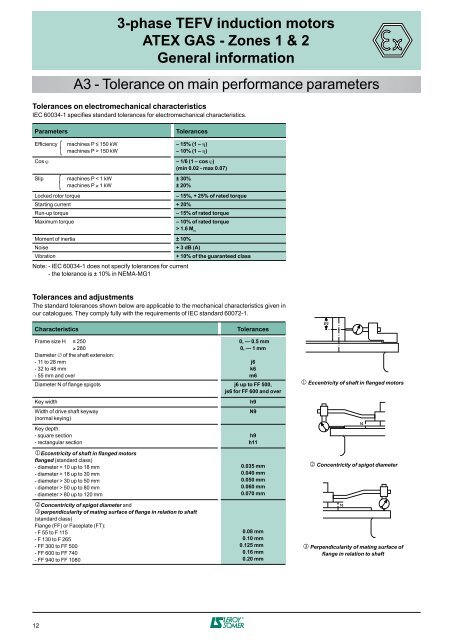
j Eccentricity of shaft in flanged <strong>motors</strong><br />
k Concentricity of spigot diameter<br />
10<br />
l Perpendicularity of mating surface of<br />
flange in relation to shaft<br />
10