SIMOVERT MASTERDRIVES Vector Control - MEYLE - Meyer ...
SIMOVERT MASTERDRIVES Vector Control - MEYLE - Meyer ...
SIMOVERT MASTERDRIVES Vector Control - MEYLE - Meyer ...

Create successful ePaper yourself
Turn your PDF publications into a flip-book with our unique Google optimized e-Paper software.
Cabinet units<br />
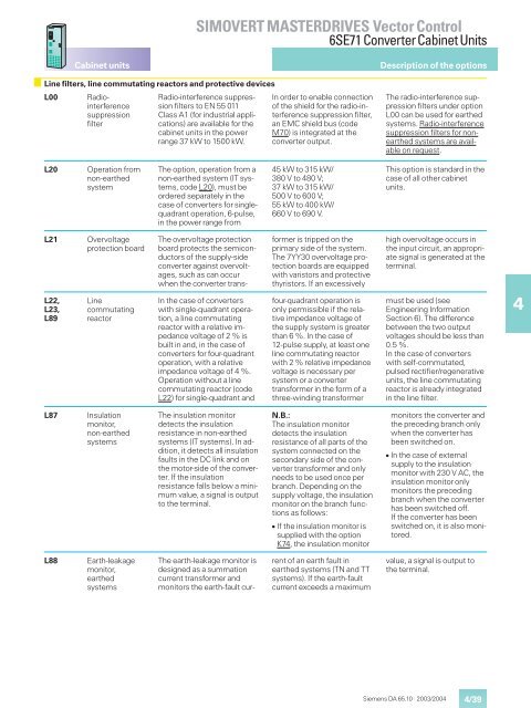
Line filters, line commutating reactors and protective devices<br />
L00 Radiointerference<br />
suppression<br />
filter<br />
L20 Operation from<br />
non-earthed<br />
system<br />
L21 Overvoltage<br />
protection board<br />
L22, Line<br />
L23, commutating<br />
L89 reactor<br />
L87 Insulation<br />
monitor,<br />
non-earthed<br />
systems<br />
L88 Earth-leakage<br />
monitor,<br />
earthed<br />
systems<br />
<strong>SIMOVERT</strong> <strong>MASTERDRIVES</strong> <strong>Vector</strong> <strong>Control</strong><br />
6SE71 ConverterCabinet Units<br />
Radio-interference suppression<br />
filters to EN 55 011<br />
Class A1 (for industrial applications)<br />
are available for the<br />
cabinet units in the power<br />
range 37 kW to 1500 kW.<br />
The option, operation from a<br />
non-earthed system (IT systems,<br />
code L20), must be<br />
ordered separately in the<br />
case of converters for singlequadrant<br />
operation, 6-pulse,<br />
in the power range from<br />
The overvoltage protection<br />
board protects the semiconductors<br />
of the supply-side<br />
converter against overvoltages,<br />
such as can occur<br />
when the converter trans-<br />
In the case of converters<br />
with single-quadrant operation,<br />
a line commutating<br />
reactor with a relative impedance<br />
voltage of2%is<br />
built in and, in the case of<br />
converters for four-quadrant<br />
operation, with a relative<br />
impedance voltage of 4 %.<br />
Operation without a line<br />
commutating reactor (code<br />
L22) for single-quadrant and<br />
The insulation monitor<br />
detects the insulation<br />
resistance in non-earthed<br />
systems (IT systems). In addition,<br />
it detects all insulation<br />
faults in the DC link and on<br />
the motor-side of the converter.<br />
If the insulation<br />
resistance falls below a minimum<br />
value, a signal is output<br />
to the terminal.<br />
The earth-leakage monitor is<br />
designed as a summation<br />
current transformer and<br />
monitors the earth-fault cur-<br />
In order to enable connection<br />
of the shield for the radio-interference<br />
suppression filter,<br />
an EMC shield bus (code<br />
M70) is integrated at the<br />
converter output.<br />
45 kW to 315 kW/<br />
380 V to 480 V;<br />
37 kW to 315 kW/<br />
500Vto600V;<br />
55 kW to 400 kW/<br />
660 V to 690 V.<br />
former is tripped on the<br />
primary side of the system.<br />
The 7YY30 overvoltage protection<br />
boards are equipped<br />
with varistors and protective<br />
thyristors. If an excessively<br />
four-quadrant operation is<br />
only permissible if the relative<br />
impedance voltage of<br />
the supply system is greater<br />
than 6 %. In the case of<br />
12-pulse supply, at least one<br />
line commutating reactor<br />
with2%relative impedance<br />
voltage is necessary per<br />
system or a converter<br />
transformer in the form of a<br />
three-winding transformer<br />
N.B.:<br />
The insulation monitor<br />
detects the insulation<br />
resistance of all parts of the<br />
system connected on the<br />
secondary side of the converter<br />
transformer and only<br />
needs to be used once per<br />
branch. Depending on the<br />
supply voltage, the insulation<br />
monitor on the branch functions<br />
as follows:<br />
� If the insulation monitor is<br />
supplied with the option<br />
K74, the insulation monitor<br />
rent of an earth fault in<br />
earthed systems (TN and TT<br />
systems). If the earth-fault<br />
current exceeds a maximum<br />
Description of the options<br />
The radio-interference suppression<br />
filters under option<br />
L00 can be used for earthed<br />
systems. Radio-interference<br />
suppression filters for nonearthed<br />
systems are available<br />
on request.<br />
This option is standard in the<br />
case of all other cabinet<br />
units.<br />
high overvoltage occurs in<br />
the input circuit, an appropriate<br />
signal is generated at the<br />
terminal.<br />
must be used (see<br />
Engineering Information<br />
Section 6). The difference<br />
between the two output<br />
voltages should be less than<br />
0.5 %.<br />
In the case of converters<br />
with self-commutated,<br />
pulsed rectifier/regenerative<br />
units, the line commutating<br />
reactor is already integrated<br />
in the line filter.<br />
monitors the converter and<br />
the preceding branch only<br />
when the converter has<br />
been switched on.<br />
� In the case of external<br />
supply to the insulation<br />
monitor with 230 V AC, the<br />
insulation monitor only<br />
monitors the preceding<br />
branch when the converter<br />
has been switched off.<br />
If the converter has been<br />
switched on, it is also monitored.<br />
value, a signal is output to<br />
the terminal.<br />
Siemens DA 65.10 · 2003/2004<br />
4/39<br />
4