SIMOVERT MASTERDRIVES Vector Control - MEYLE - Meyer ...
SIMOVERT MASTERDRIVES Vector Control - MEYLE - Meyer ...
SIMOVERT MASTERDRIVES Vector Control - MEYLE - Meyer ...

Create successful ePaper yourself
Turn your PDF publications into a flip-book with our unique Google optimized e-Paper software.
<strong>SIMOVERT</strong> <strong>MASTERDRIVES</strong> <strong>Vector</strong> <strong>Control</strong><br />
Engineering Information<br />
Compact and chassis units<br />
Cabinet units System components<br />
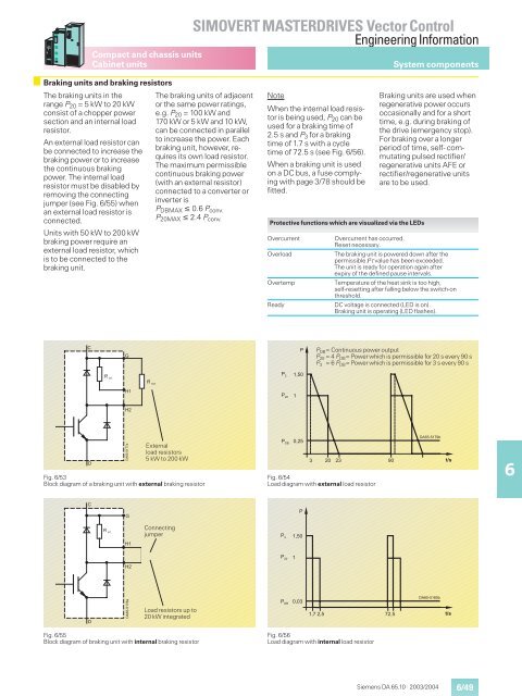
Braking units and braking resistors<br />
The braking units in the<br />
range P20 =5kWto20kW<br />
consist of a chopper power<br />
section and an internal load<br />
resistor.<br />
An external load resistor can<br />
be connected to increase the<br />
braking power or to increase<br />
the continuous braking<br />
power. The internal load<br />
resistor must be disabled by<br />
removing the connecting<br />
jumper (see Fig. 6/55) when<br />
an external load resistor is<br />
connected.<br />
Units with 50 kW to 200 kW<br />
braking power require an<br />
external load resistor, which<br />
is to be connected to the<br />
braking unit.<br />
�<br />
�<br />
The braking units of adjacent<br />
or the same power ratings,<br />
e.g. P20 = 100 kW and<br />
170 kW or 5 kW and 10 kW,<br />
can be connected in parallel<br />
to increase the power. Each<br />
braking unit, however, requires<br />
its own load resistor.<br />
The maximum permissible<br />
continuous braking power<br />
(with an external resistor)<br />
connected to a converter or<br />
inverter is<br />
PDBMAX � 0.6 Pconv.<br />
P20MAX � 2.4 Pconv.<br />
Fig. 6/53<br />
Block diagram of a braking unit with external braking resistor<br />
�<br />
�<br />
�� ����<br />
�� ����<br />
�<br />
��<br />
��<br />
����������<br />
�� ����<br />
External<br />
load resistors<br />
5kWto200kW<br />
Fig. 6/55<br />
Block diagram of braking unit with internal braking resistor<br />
�<br />
��<br />
��<br />
����������<br />
Connecting<br />
jumper<br />
Load resistors up to<br />
20 kW integrated<br />
Note<br />
When the internal load resistor<br />
is being used, P20 can be<br />
used for a braking time of<br />
2.5 s and P3 for a braking<br />
time of 1.7 s with a cycle<br />
time of 72.5 s (see Fig. 6/56).<br />
When a braking unit is used<br />
on a DC bus, a fuse complying<br />
with page 3/78 should be<br />
fitted.<br />
Protective functions which are visualized via the LEDs<br />
� �<br />
� ��<br />
� ��<br />
����<br />
�<br />
����<br />
�<br />
��<br />
��<br />
Fig. 6/54<br />
Load diagram with external load resistor<br />
Braking units are used when<br />
regenerative power occurs<br />
occasionally and for a short<br />
time, e.g. during braking of<br />
the drive (emergency stop).<br />
For braking over a longer<br />
period of time, self- commutating<br />
pulsed rectifier/<br />
regenerative units AFE or<br />
rectifier/regenerative units<br />
are to be used.<br />
Overcurrent Overcurrent has occurred.<br />
Reset necessary.<br />
Overload The braking unit is powered down after the<br />
permissible I2t value has been exceeded.<br />
The unit is ready for operation again after<br />
expiry of the defined pause intervals.<br />
Overtemp Temperature of the heat sink is too high,<br />
self-resetting after falling below the switch-on<br />
threshold.<br />
Ready DC voltage is connected (LED is on).<br />
Braking unit is operating (LED flashes).<br />
� �<br />
� ��<br />
� ��<br />
�<br />
� P DB= Continuous power output<br />
P 20 =4P DB= Power which is permissible for 20 s every 90 s<br />
P 3 =6P DB= Power which is permissible for 3 s every 90 s<br />
�<br />
����<br />
����<br />
��� ���<br />
Fig. 6/56<br />
Load diagram with internal load resistor<br />
��<br />
����<br />
����������<br />
����������<br />
Siemens DA 65.10 · 2003/2004<br />
���<br />
���<br />
6/49<br />
6