You also want an ePaper? Increase the reach of your titles
YUMPU automatically turns print PDFs into web optimized ePapers that Google loves.
Technische Information Technical information<br />
und Bedienungsanleitung and operating instruction<br />
Ausgabe: 1 Gültig ab: 17.10.2006<br />
Version: 1 valid from: 17.10.2006<br />
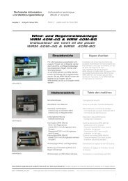
Synchronmodul SM2 ...A/...A<br />
Synnchro module SM2 ...A/...A<br />
<strong>STG</strong><br />
BEIKIRCH<br />
Zum Betrieb mehrerer Antriebe an einem Fenster, je nach Ausführung in Kombination mit einer Zusatzverreigelung<br />
To operate several motor units on the same window, depending on type in combination with additional locking<br />
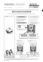
Technische Maße Technical dimensions<br />
130 mm<br />
95 mm<br />
56 mm<br />
Sicherheit auf<br />
höchstem Niveau<br />
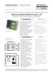
Einsatzbereich Area of application<br />
Das Synchronmodul SM2 ist eine mikroprozessorgesteuerte<br />
Gleichlauf- und Abschaltsteuerung<br />
für die gleichzeitige Betätigung<br />
mehrerer Rauchabzugs- und/oder<br />
Lüftungsantriebe 24 V DC an einem<br />
Öffnungselement (Flügel/Kuppel usw.).<br />
Mehrere Synchronmodule können innerhalb<br />
einer Motorgruppe parallel angesteuert<br />
werden.<br />
Der Typ der SM2 wird durch die Anwendung<br />
und die Stromaufnahme der Antriebe<br />
bestimmt. Je nach Ausführung der SM2 ist<br />
eine Kombination mit Zusatzverriegelung<br />
möglich.<br />
Das Synchronmodul erkennt die Taktfrequenz<br />
der Antriebe über die eingebauten<br />
Signalgeber. Während des Antriebslaufes<br />
werden die Eingangssignale ständig<br />
verglichen und überwacht. Kommt es zu<br />
lastbedingten Differenzen, so werden<br />
diese automatisch ausgeglichen und ein<br />
exakter Gleichlauf wird gewährleistet.<br />
In den Endstellungen und bei Überlast in<br />
den Zwischenstellungen schalten die<br />
Antriebe durch die integrierte stromabhängige<br />
Überlastabschaltung ab.<br />
Das Synchronmodul SM2 ist softwareverriegelt<br />
und kann nach der Endabschaltung<br />
nur in Gegenrichtung angesteuert<br />
werden.<br />
Defekte oder fehlende Antriebe werden<br />
erkannt. Eine Ansteuerung weiterer<br />
angeschlossener Antriebe wird unterbunden,<br />
um eine Zerstörung des Öffnungsflügels<br />
zu verhindern.<br />
verschiedene Anwendungsmöglichkeiten,<br />
wie Synchronbetrieb, Master- /<br />
Slavebetrieb, als Folgesteuerung in<br />
Kombination mit Zusatzverriegelung<br />
Ausgleich von Laufzeitunterschieden<br />
durch integrierte Nachlaufzeiten<br />
zum Betrieb von Antrieben mit Signalgebern,<br />
ohne Endschalter, ohne eingebaute<br />
Lastabschaltung<br />
zum Betrieb von Riegelantrieben ohne<br />
Signalgeber, ohne Endschalter, ohne<br />
eingebaute Lastabschaltung<br />
The synchro module SM2 is a microprocessor-controlled<br />
synchronisation and cutoff<br />
control for the simultaneous actuation<br />
of several SHE and/or ventilation drives<br />
24 V DC on an opening unit (window<br />
casement / dome light etc.).<br />
Several synchro modules of the same<br />
group of motors are parallel controlled.<br />
The application and the power consumption<br />
of the drives determines the type of the<br />
SM2. Depending on the type of SM2 a<br />
combination with additional locking is<br />
possible.<br />
The integrated pulse generator of the<br />
synchro module identifies the frequency of<br />
the drives. During running of the drives the<br />
input signals are compared and controlled<br />
constantly. Differences are compensated<br />
automatically and an accurate<br />
synchronisation is guaranted.<br />
In the end positions and by overload in<br />
intermediate positions the drives cut-off<br />
through the integrated power cut-off.<br />
The synchro module SM2 is softwarelatched<br />
and after cut-out in an end<br />
position can only be actuated in the<br />
opposite direction.<br />
Defective or missing drives are detected.<br />
The activation of other connected drives is<br />
stopped to avoid the destruction of the<br />
window.<br />
Besonderheiten Special features<br />
various applications such as synchro<br />
operation, master/slave operation or as<br />
sequential control in combination with<br />
additional locking<br />
compensation of different operating<br />
times by integrated follow-up times<br />
to connect drives with pulse generator,<br />
without integrated limit switches, without<br />
integrated electronic power cut-offs<br />
to connect locking motors without pulse<br />
generator, without integrated limit<br />
switches, without integrated electronic<br />
power cut-offs<br />
Diese Bedienungsanleitung für späteren Gebrauch bzw. Wartung aufbewahren. Please keep these operating instruction for future reference and maintance.<br />
Datei: Änderungen dienen dem technischen Fortschritt und bleiben vorbehalten. Abbildungen unverbindlich. Subject to technical modifications. Diagram is not binding.<br />
Ti_SM2_dt_engl.cdr<br />
Art.Nr. 24999658<br />
D<br />
GB
Sicherheitshinweise<br />
Sicherheitshinweise, die Sie unbedingt beachten müssen,<br />
werden durch besondere Zeichen hervorgehoben<br />
Vorsicht / Warnung / Achtung<br />
Gefahr für Personen durch elektrischen Strom<br />
Vorsicht / Warnung / Achtung<br />
Nichtbeachtung führt zur Zerstörung Gefährdung<br />
für Material durch falsche Handhabung<br />
Vorsicht / Achtung / Warnung<br />
Gefährdung für Personen durch Gefahren aus<br />
dem Gerätebetrieb. Quetsch- und Klemmgefahr<br />
INFO<br />
Warnung 230 V AC<br />
Gefährliche Spannung. Kann Tod, schwere Körperverletzung oder<br />
erheblichen Sachschaden verursachen. Trennen Sie das Gerät<br />
allpolig von der Versorgungsspannung bevor Sie es öffnen,<br />
montieren oder den Aufbau verändern. VDE 0100 für 230 V<br />
Netzanschluss beachten.<br />
Beachten Sie bei der Montage und Bedienung<br />
Das Fenster schließt automatisch.<br />
Beim Schließen und Öffnen stoppt der Antrieb über die<br />
Lastabschaltung. Die entsprechende Druckkraft entnehmen Sie<br />
bitte den technischen Daten. Die Druckkraft reicht aber auf jeden<br />
Fall aus bei Unachtsamkeit Finger zu zerquetschen.<br />
Bei der Montage und Bedienung nicht in den Fensterfalz und in<br />
den laufenden Antrieb greifen!<br />
Quetsch- und Klemmgefahr!<br />
Bedienungsanleitung<br />
für die fachgerechte Montage, Installation und angemessene Wartung durch<br />
den geschulten, sachkundigen und sicherheitsbewussten Elektro-Installateur<br />
und / oder Fachpersonal mit Kenntnissen der elektrischen Geräteinstallation.<br />
Lesen und Beachten Sie die Angaben in dieser Bedienungsanleitung und<br />
halten Sie die vorgegebene Reihenfolge ein.<br />
Diese Bedienungsanleitung für späteren Gebrauch / Wartung aufbewahren.<br />
Ein zuverlässiger Betrieb und ein Vermeiden von Schäden und Gefahren ist<br />
nur bei sorgfältiger Montage und Einstellung nach dieser Anleitung gegeben.<br />
Bitte beachten Sie genau die Anschlussbelegung, die minimalen und<br />
maximalen Leistungsdaten (siehe technischen Daten) und die<br />
Installationshinweise.<br />
Anwendungsbereich<br />
ausschließlich für automatisches Öffnen und Schließen der angegebenen<br />
Fensterformen. Weitere Anwendungen im Werk erfragen.<br />
Es würde den Rahmen dieser Bedienungsanleitung sprengen, alle gültigen<br />
Bestimmungen und Richtlinien aufzulisten.<br />
Prüfen Sie immer, ob Ihre Anlage den gültigen Bestimmungen entspricht.<br />
Besondere Beachtung finden dabei: Öffnungsquerschnitt des Fensters,<br />
Öffnungszeit und Öffnungsgeschwindigkeit, Temperaturbeständigkeit von<br />
Kabel und Geräten. Benötigtes Befestigungsmaterial ist mit dem Baukörper<br />
und der entsprechenden Belastung abzustimmen und, wenn nötig, zu<br />
ergänzen. Ein eventuell mitgeliefertes Befestigungsmaterial entspricht nur<br />
einem Teil der Erfordernisse.<br />
Wartungsarbeiten<br />
Werden die Geräte in Rauch- und Wärmeabzugsanlagen (kurz RWA)<br />
eingesetzt, müssen sie mindestens einmal jährlich geprüft, gewartet und ggf.<br />
instand gesetzt werden. Bei reinen Lüftungsanlagen ist dies auch zu<br />
empfehlen.<br />
Die Geräte von Verunreinigungen befreien. Befestigungs- und Klemmschrauben<br />
auf festen Sitz prüfen. Die Geräte durch Probelauf testen. Das<br />
Motorgetriebe ist wartungsfrei. Defekte Geräte dürfen nur in unserem Werk<br />
instand gesetzt werden. Es sind nur Original-Ersatzteile einzusetzen. Die<br />
Betriebsbereitschaft ist regelmäßig zu prüfen. Ein Wartungsvertrag ist<br />
empfehlenswert. Alle serienmäßig mit der RWA-Steuerzentrale gelieferten<br />
Akkus bedürfen einer regelmäßigen Kontrolle im Rahmen der Wartung und<br />
sind nach der vorgeschriebenen Betriebszeit (ca. 4 Jahre) auszutauschen.<br />
Bei der Entsorgung der verwendeten Gefahrstoffe - z.B. Akkus - Gesetze<br />
beachten.<br />
2<br />
Caution / Warning / Attention<br />
Danger to persons due to electricity<br />
Caution / Warning / Attention<br />
Non-observance leads to destruction<br />
Danger to material due to incorrect handling<br />
Caution / Attention / Warning<br />
Danger to persons due to risks arising from the<br />
operation of the equipment. Danger of crushing/trapping<br />
INFO<br />
Safety instructions<br />
Please observe the following safety which are emphasized<br />
by special symbols<br />
Warning 230 V AC<br />
Dangerous voltage. Can cause death, serious injury or<br />
considerable material damage. Disconnect the equipment from the<br />
power supply at all poles before opening, assembling or carrying<br />
out any structural alterations. Observe VDE 0100 for<br />
230 V power connection.<br />
Please observe the following for assembly and operation<br />
The window closes automatically.<br />
When opening and closing, the drive unit is stopped by the power<br />
cut-off. The corresponding pressure force is listed in the technical<br />
data. Take care - the pressure force is high enough to crush your<br />
fingers.<br />
During assembly and operation, do not interfere with the window<br />
gap or the travelling drive!<br />
Danger of crushing/trapping!<br />
Operating instructions<br />
for professional assembly, installation and appropriate maintenance by<br />
trained, qualified and safety-conscious electricians and/or skilled staff with<br />
knowledge of electrical equipment installation.<br />
Read and observe the information contained in these operating instructions<br />
and respect the order of procedure stated therein.<br />
Please keep these operating instructions for future reference and<br />
maintenance. Reliable operation and the prevention of damage and risks are<br />
only granted if the equipment is assembled carefully and the settings are<br />
carried out according to these instructions and to the operating instructions<br />
of the drives.<br />
Please observe the exact terminal assignment, the minimum and maximum<br />
power ratings (see technical data) and the installation instructions.<br />
Application range<br />
Exclusively for the automatic opening and closing of the stated types of<br />
windows. For further application, please contact the manufacturer.<br />
It would be beyond the scope of these safety instructions to list all the valide<br />
regulations and guidelines.<br />
Always make sure that your system corresponds to the valid regulations. Pay<br />
particular attention to: the aperture cross-section of the window, the opening<br />
time and opening speed, the temperature resistance of the cables and<br />
equipment, cross-sections of the cables in relation to the cable lengths and<br />
power consumption. Required mounting material is to be adapted to the<br />
frame and the corresponding load and is to be completed, if necessary. Any<br />
supplied mounting material is only part of the required amount.<br />
Maintenance works<br />
If the equipment is employed in smoke heat extraction systems (in short<br />
SHE), they must be checked, serviced and, if required, repaired at least<br />
once per year. This is also recommended for pure ventilation systems.<br />
Free the equipment from any contamination. Check the tightness of fixing<br />
and clamping screws. Test the equipment by trial run.<br />
The gear system is maintenance free. Defective equipment must only be<br />
repaired in our factory. Only original spare parts are to be used.<br />
The readiness for operation has to be checked regularly. For this purpose a<br />
service contract is recommended. All batteries provided with the SHE control<br />
centre need to be regularly checked as part of the maintenance programme<br />
and have to be replaced after their specified service life (approx. 4 years).<br />
Please observe the legal requirements when disposing of hazardous<br />
material - e.g. batteries.
Sicherheitshinweise Safety instructions<br />
Leitungsverlegung und elektrischer Anschluss nur durch<br />
zugelassene Elektrofirma. Netzzuleitungen 230 V AC separat<br />
bauseits absichern. Netzzuleitungen bis an die Netzklemme<br />
ummantelt lassen.<br />
Bei der Installation DIN- und VDE-Vorschriften beachten, VDE 0100<br />
Errichten von Starkstromanlagen bis 1000 V, VDE 0815<br />
Installationskabel und -leitungen, VDE 0833 Gefahrenmeldeanlagen<br />
für Brand, Einbruch und Überfall.<br />
Kabeltypen ggf. mit den örtlichen Abnahmebehörden, Energieversorgungsunternehmen,<br />
Brandschutzbehörden oder Berufsgenossenschaften<br />
festlegen.<br />
Alle Niederspannungsleitungen (24 V DC) getrennt von Starkstromleitungen<br />
verlegen. Flexible Leitungen dürfen nicht eingeputzt<br />
werden. Frei hängende Leitungen mit Zugentlastung versehen. Die<br />
Leitungen müssen so verlegt sein, dass sie im Betrieb weder<br />
abgeschert, verdreht noch abgeknickt werden.<br />
Abzweigdosen müssen für Wartungsarbeiten zugänglich sein.<br />
Die Kabelarten, -längen und -querschnitte gemäß den technischen<br />
Angaben ausführen.<br />
Vor jeder Wartungsarbeit oder Veränderung des Aufbaus<br />
sind die Netzspannung und Akkus allpolig abzuklemmen.<br />
Gegen unbeabsichtigtes Wiedereinschalten ist<br />
die Anlage abzusichern. Elektrische Steuerungen<br />
müssen stromlos sein, bevor Sie Teile entnehmen oder<br />
dazusetzen (Netzspannung und Akkus abklemmen).<br />
Nach der Installation und jeder Veränderung der Anlage alle<br />
Funktionen durch Probelauf überprüfen.<br />
Beachten Sie bei der Montage und Bedienung: Die Fenster<br />
schließen automatisch.<br />
Quetsch- und Scherstellen zwischen Fensterflügel und Rahmen,<br />
Lichtkuppeln und Aufsetzkranz müssen bis zu einer Höhe von<br />
2,5 m durch Einrichtungen gesichert sein, die bei Berührung oder<br />
Unterbrechung durch eine Person, die Bewegung zum Stillstand<br />
bringen (Richtlinie für kraftbetätigte Fenster, Türen und Tore der<br />
Berufsgenossenschaften).<br />
Achtung! Die Antriebe und Bedienstellen niemals an<br />
230 V anschließen! Sie sind für 24 V gebaut!<br />
Lebensgefahr!<br />
Bei Anwendungen am Kippfenster muss eine Kippfang-<br />
Sicherungsschere eingebaut werden. Sie verhindert Schäden, die<br />
bei unsachgemäßer Montage und Handhabung auftreten können.<br />
Bitte beachten: die Kippfang-Sicherungsschere muss mit dem<br />
Öffnungshub des Antriebes abgestimmt sein. Das heißt, die<br />
Öffnungsweite der Kippfang-Sicherungsschere muss, um eine<br />
Blockade zu vermeiden, größer als der Antriebshub sein. Siehe<br />
Richtlinie für kraftbetätigte Fenster, Türen und Tore.<br />
Schützen Sie alle Aggregate dauerhaft vor Wasser und Schmutz.<br />
Achtung: Die Antriebe nur mit Steuerungen vom gleichen<br />
Hersteller betreiben. Bei Verwendung von Fremdfabrikaten<br />
keine Haftung, Garantie- und Serviceleistungen.<br />
Die Montage und Installation muss sachgemäß,<br />
sicherheitsbewusst und nach Angaben der<br />
Bedienungsanleitung erfolgen. Werden Ersatzteile,<br />
Ausbauteile oder Erweiterungen benötigt bzw.<br />
gewünscht, ausschließlich Original-Ersatzteile<br />
verwenden.<br />
Herstellererklärung<br />
Die Geräte sind gemäß der europäischen Richtlinien geprüft und<br />
hergestellt. Eine entsprechende Herstellererklärung liegt vor. Sie<br />
dürfen die Geräte nur dann betreiben, wenn für das Gesamtsystem<br />
eine Konformitätserklärung vorliegt.<br />
Routing of cables and electrical connections only to be done by a<br />
qualified electrician. Power supply leads 230 V AC to be fused<br />
separately by the customer. Keep power supply leads sheathed<br />
until the mains terminal.<br />
DIN and VDE regulations to be observed for the installation: VDE<br />
0100 Setting up of high voltage installations up to 1000 V. VDE<br />
0815 Installation cables and wires. VDE 0833 Alarm systems for<br />
fire, break-in and burglary.<br />
Cable types to be agreed with local inspection authorities, power<br />
utilities, fire protection authority and the professional associations.<br />
All low voltage cables (24 V DC) to be installed separately from<br />
high voltage cables. Flexible cables must not be plastered in.<br />
Provide tension relief for freely suspended cables. The cables must<br />
be installed in such a way that they cannot be sheared off, twisted<br />
or bent off during operation. Junction boxes must be accessible for<br />
maintenance work. Adhere to the type of cables, cable lengths and<br />
cross-sections as stated in the technical information.<br />
The supply voltage and the batteries are to be<br />
disconnected at all poles before maintenance work or<br />
structural alterations. The system must be protected<br />
against unintentional re-starting. Electrical controls must<br />
be voltage free before extension modules are taken off<br />
or added (disconnect mains voltage and batteries).<br />
After installation and any changes to the system check all functions<br />
by a trial run.<br />
During assembly and operation, please observe: the windows may<br />
close automatically.<br />
Potential crushing and cutting points between the casement and<br />
the window frame, dome lights and support frame must be secured<br />
up to a height of 2.5 m by safety equipment, which if touched or<br />
interrupted by a person will immediately stop the movement<br />
(guideline for power operated windows, doors and gates of the<br />
professional association).<br />
Warning! Never connect the drives and call points to<br />
230 V! They are built for 24 V!<br />
Risk of death!<br />
For applications: Tilt windows: A scissor-type safety catch is to be<br />
installed. It prevents damage caused by incorrect assembly and<br />
handling. Please observe: the scissor-type safety catch must be<br />
adapted to the opening stroke of the drive unit, i.e. that the opening<br />
of the safety catch must be larger than the drive unit stroke in order<br />
to prevent blocking. See guideline for power-operated windows,<br />
doors and gates.<br />
Provide all aggregates with durable protection against water and<br />
dirt!<br />
Attention: The control must only be operated with drives<br />
made by the same manufacturer. No liability will be<br />
accepted and no guarantee nor service is granted if<br />
products of outside manufacturers are used. Assembly<br />
and installation must be carried out properly, according<br />
to the information of the operating instructions paying<br />
particular attention to safety aspects. If spare parts,<br />
dismantled parts or extension components are required<br />
or desired, only use original spare parts.<br />
Manufacturer’s declaration<br />
The equipment has been manufactured and tested according to<br />
the European regulations. A corresponding manufacturer’s<br />
declaration has been submitted. You may only operate the system<br />
if a Declaration of Conformity exists for the entire system.<br />
3<br />
D<br />
GB
Typenbezeichnung<br />
Type<br />
Mastermodul mit 1 Antrieb<br />
Master module with one drive<br />
Mastermodul mit 2 Antrieben<br />
Master module with two drives<br />
4<br />
Zum Anschluss einer Zusatzverriegelung<br />
To connect an additional locking<br />
Mastermodul<br />
Master module<br />
Slavemodul<br />
Slave module<br />
Abschaltstrom für Richtung “Auf”<br />
Cut-off current in direction “open”<br />
Abschaltstrom für Richtung “Zu”<br />
Cut-off current in direction “closed”<br />
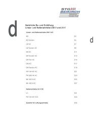
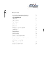
Beschreibung<br />
Die Anschlusswerte der Synchromodule sind mit den Abschaltströmen<br />
der Antriebe gemäß Tabelle zu vergleichen.<br />
Die Nennströme können abhängig von der Einbausituation und<br />
den benötigten Kräften wesentlich geringer ausfallen.<br />
Tabelle<br />
Chart<br />
Varianten Versions<br />
SM2 [/1M] [/2M] [/Z] [Master] [Slave] ...A / ...A<br />
Description<br />
Compare connection values for the synchro module unit with the<br />
current values for the drives according to the chart.<br />
Nominal current requirements could be substantially less,<br />
depending on the force required for a specific mounting situation.<br />
Linearantrieb Abschaltströme Hebe-/Senkbetrieb SM2 Typ<br />
Linear drive Cut-off current extension/retraction Type of SM2<br />
2 x M2 500 N 2 x 1,0 A / 1,0 A SM2 1,0 A / 1,0 A<br />
2 x M2 1000 N 1G 2 x 1,0 A / 1,0 A SM2 1,0 A / 1,0 A<br />
2 x M2 1000 N 2G 2 x 1,5 A / 1,5 A SM2 1,5 A / 1,5 A<br />
2 x M6 500 N 2 x 0,85 A / 0,85 A SM2 0,85 A / 0,85 A<br />
2 x M7 500 N und 1000 N 2 x 0,85 A / 0,85 A SM2 0,85 A / 0,85 A<br />
2 x M8 650 N 2 x 1,0 A / 1,0 A SM2 1,0 A / 1,0 A<br />
2 x M9 650 N 2 x 1,0 A / 1,0 A SM2 1,0 A / 1,0 A<br />
2 x M9 1500 N 2 x 1,9 A / 1,9 A SM2 1,9 A / 1,9 A<br />
2 x M9/2 650 N 2 x 1,0 A / 1,0 A SM2 1,0 A / 1,0 A<br />
2 x M9/2 1000 N 2 x 1,3 A / 1,3 A SM2 1,4 A / 1,4 A<br />
2 x M9/2 1500 N 2 x 2,5 A / 2,5 A SM2 2,5 A / 2,5 A<br />
2 x M10/2 1500 N 2 x 3,5 A / 2,5 A SM2 3,5 A / 2,5 A<br />
2 x M10/2 2000 N 2 x 4,0 A / 3,0 A SM2 4,0 A / 3,0 A
Beschreibung Description<br />
Antriebe im eingefahrenen Zustand montieren. Sichere Befestigung<br />
von Konsole und Flügelbock beachten (siehe Anleitung Antrieb).<br />
Die Flügel müssen in “ZU”-Stellung fest und dicht geschlossen<br />
sein. Antriebe nicht ohne angeschlossenes Synchronmodul<br />
betreiben!<br />
Das Synchronmodul in der Nähe der Antriebe montieren. Das<br />
Anschlusskabel muss direkt (ohne Zwischenklemmung) auf das<br />
Synchronmodul angeschlossen werden.<br />
Bei Verbindung mehrerer Synchronmodule mit Busverbindung<br />
beträgt der Abstand zwischen den 2 Modulen max. 5 m.<br />
Die BUS-Verbindungsleitung und Abschirmung (shield) nach<br />
Anschlussplan auflegen (siehe “Klemmenbelegung”).<br />
Der Querschnitt der Motorzuleitung von der Zentrale bis zum<br />
letzten Synchronmodul ist auf die Leitungslänge anzupassen.<br />
Große Leitungsquerschnitte nicht in die Gerätedose hineinzwingen,<br />
ggf. Leitung reduzieren bzw. flexibel anschließen! Die Platine des<br />
Synchronmoduls nicht an den Bauteilen anfassen!<br />
Anschluss Zuleitung von der Zentrale zu den Klemmen 1-2-3 in<br />
dem (den) Synchronmodul(en) herstellen. Brücke “E” für die<br />
Überwachung nur im einzigen bzw. letzten Synchronmodul einer<br />
Motorgruppe belassen. Der Abschluss der Überwachungsleitung<br />
mittels der Brücke „E“ gilt nur für Zentralensysteme mit dem Prinzip<br />
der Dioden-Leitungsüberwachung. In jedem Fall sind die Vorgaben<br />
in den technischen Dokumentationen zu den verwendeten<br />
Zentralen zu beachten!<br />
Die Antriebspaare an das Synchronmodul anschließen.<br />
Die Farben der Motorleitung nach Plan auflegen.<br />
Nach Kontrolle aller Verbindungen und Zuleitungen über die<br />
Zentrale einen “AUF” Befehl geben.<br />
Das Synchronmodul gleicht während des Betriebes evtl.<br />
Gleichlaufschwankungen aus.<br />
In der Endstellung “Auf”schalten die Antriebe gleichzeitig ab. Dies<br />
gilt auch für Überlastungen in Zwischenstellung. Die programmierte<br />
Softwareverriegelung erlaubt anschließend nur einen Befehl in<br />
Gegenrichtung und sperrt weitere „AUF“ Befehle.<br />
Über die Zentrale einen „ZU“ Befehl geben.<br />
In der Endstellung „ZU“ schalten die Antriebe gleichzeitig ab. Dies<br />
gilt auch für Überlastung in Zwischenstellung. Die programmierte<br />
Softwareverriegelung erlaubt anschließend nur einen Befehl in<br />
Gegenrichtung und sperrt weiterere „ZU“ Befehle.<br />
Install drives in the retracted state. Ensure secure attachment of<br />
bracket and hinged bracket (see “Technical Information” of the<br />
drive). The window casement must be closed securely and tightly<br />
in the “CLOSED position”. Do not operate drives without connected<br />
synchro module!<br />
Install synchro module in the vicinity of the drives. The connecting<br />
cable must be connected directly (without any intermediate<br />
clamping) to the synchro module.<br />
In the case of connection of a number of synchro modules with bus<br />
connection the distance between the 2 modules is a maximum of 5<br />
m. Lay out BUS connecting lead and shield according to “wiring<br />
diagram”.<br />
The cross-section of the motor input line from the central control<br />
unit to the last synchro module has to be adjusted to the pipeline<br />
length. Do not try to force large cross-section leads into the<br />
equipment socket; reduce the lead size as necessary, or connect<br />
flexibly! Do not take hold of the control board of the synchro<br />
module by ist components!<br />
Make connections between input line from the central control<br />
(group module terminal block) to the terminals 1-2-3 in the synchro<br />
module(s). Leave bridge “E” for monitoring purposes only in the<br />
single or last synchro module of a motor module. Completing the<br />
monitoring line using bridge “E” works only for control systems<br />
using the principle of diode-line monitoring. Under all<br />
circumstances, pay close attention to the technical documentation<br />
accompanying each particular type of control panel!<br />
Connect the drive pairs to the synchro module. Apply the colours of<br />
the motor line according to the wiring diagram.<br />
After checking all connections and input lines send an “OPEN”<br />
command via the central control unit.<br />
The synchro module compensates for possible speed droops<br />
during operation.<br />
In the end position “OPEN” the drives traverse “on to the end stop”<br />
and switch off simultaneously. This is also true for overloads in an<br />
intermediate position. The programmed software latch then allows<br />
just one command in the opposite direction and locks other<br />
“OPEN” commands.<br />
An “CLOSE” command is sent from the control centre.<br />
n the end position “CLOSE” the drives traverse “on to the end stop”<br />
and switch off simultaneously. This is also true for overloads in an<br />
intermediate position. The programmed software latch then allows<br />
just one command in the opposite direction and locks other<br />
“CLOSE” commands.<br />
5<br />
D<br />
GB
Funktionsablauf Synchronmodul<br />
1. Die Antriebe sind in “Zu-Stellung” am dicht geschlossenen<br />
Flügel moniert.<br />
2. Ein “AUF”-Befehl öffnet die Flügel. Die Impulse der Antriebe<br />
werden gezählt und verglichen.<br />
3. Bei einer vorgegebenen minimalen Impulsdifferenz wird der<br />
schnellere Antrieb kurz angehalten, bis die Anzahl der Impulse<br />
innerhalb dieser Zeiteinheit wieder gleich ist.<br />
4. In den Endstellungen (ein Antrieb schaltet über Last ab) ist eine<br />
geringe Nachlaufzeit programmiert, damit in jedem Fall wieder<br />
bei einem Gleichstand “AUF” oder “ZU” gestartet wird. Lastoder<br />
toleranzbedingte Laufdifferenzen werden dadurch ausgeglichen.<br />
5. Bei Erkennen von<br />
- Kurzschluss im Antriebskreis<br />
- Leitungsbruch/Unterbrechnung/Nullstrom im Antriebskreis<br />
- Unterspannung<br />
schaltet die Steuerung die angeschlossenen Antriebe ab.<br />
Ein weiterer Betrieb ist nicht möglich. Der Fehler muss zuerst<br />
behoben werden (Kurzschluss/Leitungsbruch/Unterspannung/<br />
Defekt). Falls nach Zurücksetzen der Steuerung (ca. 5 Sekunden<br />
spannungsfrei) die Ursache weiterhin vorliegt, schaltet die<br />
Steuerung sofort wieder ab.<br />
6. Die Wieder-Inbetriebnahme erfolgt nach Behebung der Fehlerursache.<br />
Nach der Sicherheitsabschaltung ist nur ein Befehl in<br />
Gegenrichtung möglich.<br />
7. Den Funktionsablauf mittels “ZU”-Befehl ebenso überprüfen.<br />
Funktionsablauf Schließfolgesteuerung<br />
Erstinbetriebnahme:<br />
Bei Erstinbetriebnahme ist nach dem Anschluss zuerst ein<br />
kompletter Öffnungsvorgang (Flügel AUF-ZU; Flügel 2 öffnet nur<br />
teilweise) durchzuführen. Hierdurch wird die Schließfolgefunktion<br />
initialisiert. Anschließend ist die Ansteuerung von<br />
Zwischenstellungen möglich.<br />
Funktionstest:<br />
1. Bei Schließfolge-Funktion fahren bei einem “AUF”-Befehl<br />
zunächst die Antriebe des Mastermoduls.<br />
6<br />
Funktionsablauf Functional sequence<br />
2. Nach Erreichen der Endstellung werden die Antriebe des Slavemoduls<br />
freigeschaltet. Diese können nun beliebig AUF und ZU<br />
(Spaltlüftung/Regulierung) betätigt werden.<br />
3. Erst nach Abschaltung der Antriebe des Slavemoduls in “ZU”-<br />
Stellung werden die Antriebe des Mastermoduls automatisch<br />
“ZU”-Richtung angesteuert.<br />
Functional synchro module<br />
1. The drives are installed in the “CLOSE setting” on a tightly<br />
closed window casement.<br />
2. An “OPEN” command opens the window casement. The motors’<br />
impulses are counted and compared.<br />
3. When the differences of the impulses is less than a predetermined<br />
minimum, the faster drive is stopped until the number of<br />
impulses are equalized again during the same time period.<br />
4. In the end positions (one drive switches off as a function of load)<br />
a small follow-up time is programmed in, so that in each case<br />
the “OPEN” or “CLOSE” sequence restarts with the drives in<br />
equivalent states. Any differences in traverse behaviour caused<br />
by loads or tolerances are evened out in this manner.<br />
5. In the event of detection of:<br />
- a short-circuit in the drive circuit<br />
- a line break/intermittent fault/zero current in the drive circuit<br />
- low voltage<br />
the controller switches off the drives that are connected. No<br />
further operation is possible. The defect must first be removed<br />
(e.g. short-circuit/line break/low voltage/defect). If after reset of<br />
the controller (approx. 5 secs at zero voltage) the cause is still<br />
present, the controller immediately switches off once again<br />
6. Any re-entry into service takes place after removal of the cause<br />
of the defect. After the safety trigger only one command in the<br />
opposite direction is possible.<br />
7. Please check also functional sequence by “CLOSE” command.<br />
Functional sequence for the closing sequence control<br />
Initial operation:<br />
For the first operation after connecting up carry out first of all a<br />
complete opening procedure (window casement OPEN-CLOSED<br />
casement 2 opens only partially). Then the closing sequence<br />
function is initialised. The control of intermediate positions is then<br />
possible.<br />
Functional test:<br />
1. With the closing sequence function the drives of the master<br />
module traverse first of all on receipt of an “OPEN” command.<br />
2. After arrival at the end position the drives of the slave module are<br />
energised. These can now be activated OPEN and CLOSED<br />
(gap ventilation/regulation) as required.<br />
3. Only after switch off of the slave module drives in the “CLOSED”<br />
position are the master module drives automatically actuated in<br />
the “CLOSE” direction.
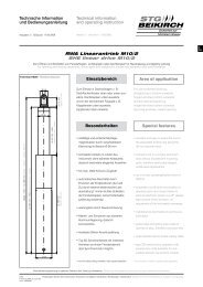
Hebe-/Senkbetrieb bei unsymmetrischen Abschaltwerten,<br />
wie z. B. SM2 4,0 A / 3,0 A.<br />
Hinweis: Bei symmetrischen Abschaltkräften kann<br />
dieses Kapitel übersprungen werden.<br />
Betriebsart „Volle Last beim Ausfahren“<br />
Beispiele für Hebe-/Senkbetrieb: Öffnen unter Volllast,<br />
“Fensterflügel drücken”.<br />
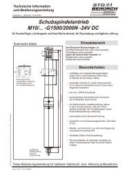
Prinzipanschluss für Antriebstypen<br />
Connection principle for type<br />
M2, M8, M9, M9/2, M10/2 ...<br />
+<br />
in<br />
braun brown<br />
M2 M2 Sig Sig Sig M2 M2 Sig Sig Sig<br />
+ - + - + - + -<br />
+ - = Auf oder Entriegeln / Open or unlock<br />
- +=ZuoderVerriegeln/Close or lock<br />
-<br />
in<br />
blau blue<br />
M =<br />
weiß white<br />
schwarz black<br />
1 1 2 2 3 3<br />
1 2 3<br />
Auf / Open = - +<br />
Zu / Close =+ -<br />
24 V DC<br />
Hebe-/Senkbetrieb Description<br />
SM2<br />
Überwachung<br />
Monitoring<br />
braun brown<br />
blau blue<br />
M =<br />
weiß white<br />
schwarz black<br />
+<br />
out<br />
-<br />
out shield<br />
braun brown<br />
weiß white<br />
... M6, M7<br />
gelb yellow<br />
M2 M2<br />
+ -<br />
M =<br />
Sig<br />
+<br />
grün green<br />
grau grey<br />
Sig Sig<br />
-<br />
Extension/retraction mode when asymmetric cut-off<br />
currents, e. g. SM2 4,0 A / 3,0 A.<br />
Note: When symmetric cut-off currents you may skip<br />
this chapter.<br />
Operating mode “opening under maximum power”<br />
Examples for extension/retraction mode: opening under max.<br />
power, “to push window” open.<br />
braun brown<br />
weiß white<br />
M2 M2<br />
+ -<br />
* * * Verkabelung siehe Anschlusspläne zu den verschiedenen Betriebsarten unter “Betriebsarten und Anschlusspläne”<br />
For wiring please see connecting diagram for the different operating modes in “Operating modes and connecting diagram”<br />
RWA-Zentrale / Spannungsversorgung 24 V DC<br />
Betriebsspannung (Klemme 1 und 2) wird für die Laufrichtungsänderung umgepolt,<br />
Klemme 3: Überwachungsleitung bei Verwendung einer RWA-Zentrale mit Überwachung der Motorlinie.<br />
SHE control centre / 24 V DC power supply<br />
Polarity of operating voltage (terminals 1 and 2) is reversed for alteration of traverse direction,<br />
Terminal 3: Monitoring line when using an SHE control centre with monitoring of the motor line.<br />
gelb yellow<br />
M =<br />
Sig<br />
+<br />
grün green<br />
grau grey<br />
Sig Sig<br />
-<br />
7<br />
D<br />
GB
Hebe-/Senkbetrieb Description<br />
Betriebsart „Volle Last beim Einfahren“<br />
Beispiele für Hebe-/Senkbetrieb: Schließen unter Volllast,<br />
“Fensterflügel ziehen”.<br />
Prinzipanschluss für Antriebstypen<br />
Connection principle for type<br />
8<br />
M2, M8, M9, M9/2, M10/2 ...<br />
+<br />
in<br />
blau blue<br />
-<br />
in<br />
braun brown<br />
M =<br />
weiß white<br />
1 1 2 2 3 3<br />
1 2 3<br />
Auf / Open = - +<br />
Zu / Close =+ -<br />
24 V DC<br />
schwarz black<br />
Überwachung<br />
Monitoring<br />
blau blue<br />
SM2<br />
braun brown<br />
RWA-Zentrale / Spannungsversorgung 24 V DC<br />
Betriebsspannung (Klemme 1 und 2) wird für die Laufrichtungsänderung umgepolt,<br />
Klemme 3: Überwachungsleitung bei Verwendung einer RWA-Zentrale mit Überwachung der Motorlinie.<br />
SHE control centre / 24 V DC power supply<br />
Polarity of operating voltage (terminals 1 and 2) is reversed for alteration of traverse direction,<br />
Terminal 3: Monitoring line when using an SHE control centre with monitoring of the motor line.<br />
M =<br />
weiß white<br />
schwarz black<br />
M2 M2 Sig Sig Sig M2 M2 Sig Sig Sig<br />
+ - + - + - + -<br />
+ - = Auf oder Entriegeln / Open or unlock<br />
- +=ZuoderVerriegeln/Close or lock<br />
+<br />
out<br />
-<br />
out shield<br />
Operating mode “closing under maximum power”<br />
Examples for extension/retraction mode: closing under max. power,<br />
“to pull window” closed.<br />
... M6, M7<br />
weiß white<br />
M2<br />
+<br />
braun brown<br />
gelb yellow<br />
M2<br />
-<br />
M =<br />
Sig<br />
+<br />
grün green<br />
grau grey<br />
Sig Sig<br />
-<br />
weiß white<br />
M2<br />
+<br />
braun brown<br />
gelb yellow<br />
M2<br />
-<br />
M =<br />
Sig<br />
+<br />
grün green<br />
grau grey<br />
Sig Sig<br />
-<br />
* *<br />
* Verkabelung siehe Anschlusspläne zu den verschiedenen Betriebsarten unter “Betriebsarten und Anschlusspläne”<br />
For wiring please see connecting diagram for the different operating modes<br />
in “Operating modes and connecting diagram”
Betriebsarten und Anschlusspläne<br />
Zwei Antriebe an einem Fenster<br />
Benötigtes Synchronmodul: 1 x SM2 ...A/ ...A.<br />
Je nach SM2-Typ geeignet für Antriebe mit Abschaltwerten bis<br />
4,0 Ampere.<br />
M<br />
SM2<br />
für for<br />
M2, M8, M9, M9/2, M10/2<br />
SM2<br />
+<br />
in<br />
braun brown<br />
M2<br />
+<br />
-<br />
in<br />
blau blue<br />
M2<br />
-<br />
M =<br />
Sig<br />
+<br />
M<br />
weiß white<br />
Sig Sig<br />
-<br />
1 1 2 2 3 3<br />
1 2 3<br />
schwarz black<br />
braun brown<br />
M1<br />
+<br />
M1<br />
-<br />
E<br />
blau blue<br />
M =<br />
Sig<br />
+<br />
weiß white<br />
Sig Sig<br />
-<br />
Hinweis:<br />
Brücke “E” nur im einzigen oder letzten<br />
Synchronmodul.<br />
Note:<br />
Bridge “E“ only in the single or last<br />
synchro module.<br />
+<br />
out<br />
RWA-Zentrale / Spannungsversorgung 24 V DC<br />
Betriebsspannung (Klemme 1 und 2) wird für die Laufrichtungsänderung umgepolt,<br />
Klemme 3: Überwachungsleitung bei Verwendung einer RWA-Zentrale mit Überwachung der Motorlinie.<br />
SHE control centre / 24 V DC power supply<br />
Polarity of operating voltage (terminals 1 and 2) is reversed for alteration of traverse direction,<br />
Terminal 3: Monitoring line when using an SHE control centre with monitoring of the motor line.<br />
schwarz black<br />
-<br />
out<br />
shield<br />
Operating modes and connecting diagram<br />
Two drives on the same window<br />
Required synchro module: 1 x SM2 ...A/ ...A.<br />
Depending on SM2 type suitable for drives with 4.0 Ampere cut-off<br />
current.<br />
für for<br />
M6, M7<br />
braun brown<br />
M2<br />
+<br />
weiß white<br />
M2<br />
-<br />
M =<br />
gelb yellow<br />
Sig<br />
+<br />
grün green<br />
grau grey<br />
Sig Sig<br />
-<br />
braun brown<br />
M2<br />
+<br />
weiß white<br />
M2<br />
-<br />
M =<br />
gelb yellow<br />
Sig<br />
+<br />
grün green<br />
grau grey<br />
Sig Sig<br />
-<br />
9<br />
D<br />
GB
Betriebsarten und Anschlusspläne<br />
Ansteuerung mehrerer Fenster, jedes mit 2 Antrieben an<br />
einem Fenster, in einer Motorgruppe<br />
Benötigtes Synchronmodule: pro Fenster 1x SM2 …A / …A<br />
Je nach SM2 Typ für Antriebe mit Abschaltwerten bis 4,0 Ampere.<br />
10<br />
M<br />
für for<br />
M6, M7<br />
SM2<br />
+<br />
in<br />
braun brown<br />
M2<br />
+<br />
SM2<br />
für for<br />
M2, M8, M9, M9/2, M10/2<br />
braun brown<br />
M2<br />
+<br />
-<br />
in<br />
weiß white<br />
M2<br />
-<br />
blau blue<br />
M2<br />
-<br />
M =<br />
gelb yellow<br />
Sig<br />
+<br />
M =<br />
Sig<br />
+<br />
grün green<br />
weiß white<br />
Sig Sig<br />
-<br />
1 1 2 2 3 3<br />
1 2 3<br />
grau grey<br />
Sig Sig<br />
-<br />
schwarz black<br />
braun brown<br />
weiß white<br />
M2<br />
+<br />
braun brown<br />
M1<br />
+<br />
M2<br />
-<br />
M1<br />
-<br />
E<br />
M M<br />
blau blue<br />
M =<br />
gelb yellow<br />
Sig<br />
+<br />
M =<br />
Sig<br />
+<br />
grün green<br />
weiß white<br />
Sig Sig<br />
-<br />
Hinweis: Brücke “E” nur im einzigen oder<br />
letzten Synchronmodul.<br />
Note: Bridge “E“ only in the single or last<br />
synchro module.<br />
+<br />
out<br />
grau grey<br />
Sig Sig<br />
-<br />
schwarz black<br />
-<br />
out<br />
shield<br />
SM2<br />
1 1 2 2 3 3<br />
RWA-Zentrale / Spannungsversorgung 24 V DC<br />
Betriebsspannung (Klemme 1 und 2) wird für die Laufrichtungsänderung umgepolt,<br />
Klemme 3: Überwachungsleitung bei Verwendung einer RWA-Zentrale mit Überwachung der Motorlinie.<br />
SHE control centre / 24 V DC power supply<br />
Polarity of operating voltage (terminals 1 and 2) is reversed for alteration of traverse direction,<br />
Terminal 3: Monitoring line when using an SHE control centre with monitoring of the motor line.<br />
+<br />
in<br />
braun brown<br />
M2<br />
+<br />
-<br />
in<br />
blau blue<br />
M2<br />
-<br />
M =<br />
Sig<br />
+<br />
weiß white<br />
Sig Sig<br />
-<br />
schwarz black<br />
M1<br />
+<br />
Operating modes and connecting diagram<br />
To control several windows, each with two drives on one<br />
window, in one motor module<br />
Required tandem power cut-off: per window 1 x SM2 ...A/ ...A.<br />
Depending on SM2 type suitable for drives with 4.0 Ampere cut-off<br />
current.<br />
braun brown<br />
M M<br />
M1<br />
-<br />
E<br />
blau blue<br />
M =<br />
Sig<br />
+<br />
Sig Sig<br />
-<br />
SM2 SM2<br />
weiß white<br />
Hinweis: Brücke “E” nur im einzigen oder<br />
letzten Synchronmodul.<br />
Note: Bridge “E“ only in the single or last<br />
synchro module.<br />
+<br />
out<br />
schwarz black<br />
-<br />
out<br />
shield<br />
+<br />
in<br />
braun brown<br />
M2<br />
+<br />
-<br />
in<br />
blau blue<br />
M2<br />
-<br />
SM2<br />
M =<br />
Sig<br />
+<br />
weiß white<br />
Sig Sig<br />
-<br />
schwarz black<br />
M1<br />
+<br />
M<br />
braun brown<br />
M1<br />
-<br />
E<br />
blau blue<br />
1 1 2 2 3 3<br />
M =<br />
Sig<br />
+<br />
Hinweis: Bei falscher Laufrichtung<br />
den Motoranschluss (+/-) umpolen.<br />
Note: If direction of rotation is<br />
incorrect change over polarities<br />
(+/-) of motor connections.<br />
weiß white<br />
Sig Sig<br />
-<br />
Hinweis: Brücke “E” nur im einzigen oder<br />
letzten Synchronmodul.<br />
Note: Bridge “E“ only in the single or last<br />
synchro module.<br />
+<br />
out<br />
schwarz black<br />
-<br />
out<br />
shield
Betriebsarten und Anschlusspläne<br />
Zwei Antriebe mit einer Zusatzverriegelung an einem<br />
Fenster<br />
Benötigtes Synchronmodul:<br />
1 x SM2/Z Master ...A/ ...A<br />
1 x SM2 Slave ...A/ ...A.<br />
Je nach SM2-Typ geeignet für Antriebe mit Abschaltwerten bis<br />
4,0 Ampere.<br />
Die Zusatzverriegelung mit festem Abschaltwert von 0,65 Ampere<br />
über das Mastermodul.<br />
Das Mastermodul gibt die Abschaltströme für das Slavemodul vor:<br />
- bei Motorströmen bis 2A=SM2Slave 0,85A - 2,0A,<br />
- bei Motorströmen bis 4A=SM2Slave 1,70A - 4,0A.<br />
Die Zusatzverriegelung und die Antriebe werden in Schließfolge<br />
angesteuert.<br />
M<br />
SM2<br />
Slave<br />
Hinweis: Der Einzelbetrieb eines Master- oder Slavemoduls<br />
ist nicht möglich.<br />
+<br />
in<br />
M2<br />
+<br />
SM2/Z<br />
Master<br />
-<br />
in<br />
SM2<br />
Master<br />
Z<br />
M2<br />
-<br />
Sig<br />
+<br />
Sig Sig<br />
-<br />
1 1 2 2 3 3<br />
1 2 3<br />
braun<br />
brown<br />
ZV<br />
24 V DC<br />
M1<br />
+<br />
M<br />
M1<br />
-<br />
E<br />
blau<br />
blue<br />
Sig<br />
+<br />
Sig Sig<br />
-<br />
Hinweis: Brücke “E” nur im einzigen oder<br />
letzten Synchronmodul.<br />
Note: Bridge “E“ only in the single or last<br />
synchro module.<br />
Zusatzverriegelung (öffnet zuerst)<br />
Additional locking (opens first)<br />
+<br />
out<br />
RWA-Zentrale / Spannungsversorgung 24 V DC<br />
Betriebsspannung (Klemme 1 und 2) wird für die Laufrichtungsänderung umgepolt,<br />
Klemme 3: Überwachungsleitung bei Verwendung einer RWA-Zentrale mit Überwachung der Motorlinie.<br />
SHE control centre / 24 V DC power supply<br />
Polarity of operating voltage (terminals 1 and 2) is reversed for alteration of traverse direction,<br />
Terminal 3: Monitoring line when using an SHE control centre with monitoring of the motor line.<br />
-<br />
out<br />
shield<br />
SM2<br />
Slave<br />
+<br />
in<br />
Operating modes and connecting diagram<br />
Two drives with one additional locking on the same<br />
window<br />
Required syynchro module:<br />
1 x SM2/Z Master ...A/ ...A<br />
1 x SM2 Slave ...A/ ...A.<br />
Depending on SM2 type suitable for drives with 4.0 Ampere cut-off<br />
current.<br />
Additonal locking with 0.65 Ampere cut-off current by master<br />
module.<br />
The cut-off currents of the slave module are depending on the<br />
master module:<br />
- motor currents up to 2A=SM2Slave 0.85A - 2.0A,<br />
- motor currents up to 4A=SM2Slave 1.70A - 4.0A.<br />
The additional locking and the drives are actuated in a closing<br />
sequence.<br />
Note: The individual operation of a master- or a slavemodule<br />
is not possible.<br />
für for<br />
M6, M7<br />
braun brown<br />
M2<br />
+<br />
braun brown<br />
M2<br />
+<br />
-<br />
in<br />
weiß white<br />
M2<br />
-<br />
blau blue<br />
M2<br />
-<br />
M =<br />
gelb yellow<br />
Sig<br />
+<br />
M =<br />
Sig<br />
+<br />
grün green<br />
weiß white<br />
Sig Sig<br />
-<br />
grau grey<br />
Sig Sig<br />
-<br />
für for<br />
M2, M8, M9, M9/2, M10/2<br />
schwarz black<br />
M1<br />
+<br />
braun brown<br />
M2<br />
+<br />
braun brown<br />
M1<br />
-<br />
E<br />
weiß white<br />
M2<br />
-<br />
blau blue<br />
1 1 2 2 3 3<br />
M =<br />
Sig<br />
+<br />
M =<br />
Sig<br />
+<br />
gelb yellow<br />
Sig Sig<br />
-<br />
weiß white<br />
Sig Sig<br />
-<br />
+<br />
out<br />
grün green<br />
Hinweis: Brücke “E” nur im einzigen oder<br />
letzten Synchronmodul.<br />
Note: Bridge “E“ only in the single or last<br />
synchro module.<br />
grau grey<br />
schwarz black<br />
-<br />
out shield<br />
Hinweis:<br />
Bei falscher Laufrichtung<br />
den Motoranschluss<br />
(+/-)<br />
umpolen.<br />
Note:<br />
If direction of rotation<br />
is incorrect change<br />
over polarities (+/-)<br />
of motor connections.<br />
Hinweis:<br />
Die Bus-Leitungen (in-out-shield) können<br />
in einem Kabel verlegt werden<br />
(z. B. J-Y(ST)Y 2 x 2 x 0.6 mm).<br />
Die Abschirmung ist dann in jeder<br />
Synchron-Gleichlaufregelung auf die<br />
Klemme “shield” auf zu legen.<br />
Note:<br />
The bus lines (in-out-shield) can be laid in<br />
one cable (e.g. J-Y(ST)Y 2 x 2 x 0.6 mm).<br />
In each use of synchronisation control the<br />
shielding is then to be attached to the<br />
“shield“ terminal<br />
11<br />
D<br />
GB
Betriebsarten und Anschlusspläne<br />
Zwei Antriebspaare in Folge, z. B. an einem Stulpflügel<br />
Benötigtes Synchronmodul:<br />
1 x SM2 Master ...A/ ...A<br />
1 x SM2 Slave ...A/ ...A.<br />
Je nach SM2-Typ geeignet für Antriebe mit Abschaltwerten bis<br />
4,0 Ampere.<br />
12<br />
Das Mastermodul gibt die Abschaltströme für das Slavemodul vor:<br />
- bei Motorströmen bis 2A=SM2Slave 0,85A - 2,0A,<br />
- bei Motorströmen bis 4A=SM2Slave 1,70A - 4,0A.<br />
Die beiden Antriebspaare werden in Schließfolge gesteuert.<br />
TLA2<br />
Slave<br />
2<br />
Hinweis: Der Einzelbetrieb eines Master- oder Slavemoduls<br />
ist nicht möglich.<br />
+<br />
in<br />
M<br />
M<br />
SM2<br />
Master<br />
-<br />
in<br />
M<br />
TLA2<br />
Master<br />
M<br />
für for<br />
M2, M8, M9, M9/2, M10/2, L11, L12<br />
braun brown<br />
blau blue<br />
1<br />
M =<br />
1 1 2 2 3 3<br />
1 2 3<br />
weiß white<br />
Öffnen: Erst Fenster 1, dann Fenster 2.<br />
Schließen: Erst Fenster 2, dann Fenster 1.<br />
Opening: first window 1, than window 2.<br />
Closing: first window 2, than window 1.<br />
schwarz black<br />
Master (öffnet zuerst)<br />
Master (opens first)<br />
E<br />
braun brown<br />
blau blue<br />
M =<br />
+<br />
out<br />
-<br />
out shield<br />
RWA-Zentrale / Spannungsversorgung 24 V DC<br />
Betriebsspannung (Klemme 1 und 2) wird für die Laufrichtungsänderung umgepolt,<br />
Klemme 3: Überwachungsleitung bei Verwendung einer RWA-Zentrale mit Überwachung der Motorlinie.<br />
SHE control centre / 24 V DC power supply<br />
Polarity of operating voltage (terminals 1 and 2) is reversed for alteration of traverse direction,<br />
Terminal 3: Monitoring line when using an SHE control centre with monitoring of the motor line.<br />
weiß white<br />
M2 M2 Sig Sig Sig M1 M1 Sig Sig Sig<br />
+ - + - + - + -<br />
Hinweis: Brücke “E” nur im einzigen oder<br />
letzten Synchronmodul.<br />
Note: Bridge “E“ only in the single or last<br />
synchro module.<br />
schwarz black<br />
Operating modes and connecting diagram<br />
Two drive pairs in a sequence, e.g. on a double vent<br />
window casement<br />
Required synchro module:<br />
1 x SM2 Master ...A/ ...A<br />
1 x SM2 Slave ...A/ ...A.<br />
Depending on SM2 type suitable for drives with 4.0 Ampere cut-off<br />
current.<br />
The cut-off currents of the slave module are depending on the<br />
master module:<br />
- motor currents up to 2A=SM2Slave 0.85A - 2.0A,<br />
- motor currents up to 4A=SM2Slave 1.70A - 4.0A.<br />
The two drive pairs are actuated in a closing sequence.<br />
für for<br />
M6, M7<br />
+<br />
in<br />
M2<br />
+<br />
braun brown<br />
-<br />
in<br />
Note: The individual operation of a master- or a slavemodule<br />
is not possible.<br />
für for<br />
M2, M8, M9, M9/2, M10/2<br />
M2 M2 Sig Sig Sig M1 M1 Sig Sig Sig<br />
+ - + - + - + -<br />
SM2<br />
Slave<br />
braun brown<br />
weiß white<br />
M2<br />
-<br />
blau blue<br />
M =<br />
gelb yellow<br />
Sig<br />
+<br />
M =<br />
grün green<br />
Sig Sig<br />
-<br />
weiß white<br />
grau grey<br />
schwarz black<br />
braun brown<br />
M2<br />
+<br />
braun brown<br />
E<br />
weiß white<br />
M2<br />
-<br />
blau blue<br />
1 1 2 2 3 3<br />
M =<br />
gelb yellow<br />
Sig<br />
+<br />
M =<br />
Sig Sig<br />
-<br />
weiß white<br />
Slave (schließt zuerst)<br />
Slave (closes first)<br />
+<br />
out<br />
grün green<br />
Hinweis: Brücke “E” nur im einzigen oder<br />
letzten Synchronmodul.<br />
Note: Bridge “E“ only in the single or last<br />
synchro module.<br />
grau grey<br />
schwarz black<br />
-<br />
out shield<br />
Hinweis:<br />
Die Bus-Leitungen (in-out-shield) können<br />
in einem Kabel verlegt werden<br />
(z. B. J-Y(ST)Y 2 x 2 x 0.6 mm).<br />
Die Abschirmung ist dann in jeder<br />
Synchron-Gleichlaufregelung auf die<br />
Klemme “shield” auf zu legen.<br />
Note:<br />
The bus lines (in-out-shield) can be laid in<br />
one cable (e.g. J-Y(ST)Y 2 x 2 x 0.6 mm).<br />
In each use of synchronisation control the<br />
shielding is then to be attached to the<br />
“shield“ terminal
Betriebsarten und Anschlusspläne<br />
Drei (5) (7) (9) (11) Antriebe an einem Fenster<br />
Benötigtes Synchronmodul:<br />
1 x SM2/1M Master ...A/ ...A<br />
1x (2x)(3x)(4x)(5x)SM2Slave ...A/ ...A.<br />
Je nach SM2-Typ geeignet für Antriebe mit Abschaltwerten bis<br />
4,0 Ampere.<br />
Das Mastermodul gibt die Abschaltströme für das (die)<br />
Slavemodul(e) vor:<br />
- bei Motorströmen bis 2A=SM2Slave 0,85A - 2,0A,<br />
- bei Motorströmen bis 4A=SM2Slave 1,70A - 4,0A.<br />
Die beiden Antriebspaare werden in Schließfolge gesteuert.<br />
M<br />
Hinweis: Der Einzelbetrieb eines Master- oder Slavemoduls<br />
ist nicht möglich.<br />
SM2<br />
Slave<br />
+<br />
in<br />
M<br />
für for<br />
M2, M8, M9, M9/2, M10/2<br />
SM2<br />
Master<br />
-<br />
in<br />
braun brown<br />
SM2/1M<br />
Master<br />
M<br />
blau blue<br />
M =<br />
1 2 3<br />
weiß white<br />
schwarz black<br />
SM2<br />
Slave<br />
M<br />
E<br />
1 1 2 2 3 3<br />
M<br />
Brücke<br />
Bridge<br />
Master (öffnet zuerst)<br />
Master (opens first)<br />
+<br />
out<br />
SM2<br />
Slave<br />
M M<br />
M2 M2 Sig Sig Sig M1 M1 Sig Sig Sig<br />
+ - + - + - + -<br />
Hinweis: Brücke “E” nur im einzigen oder<br />
letzten Synchronmodul.<br />
Note: Bridge “E“ only in the single or last<br />
synchro module.<br />
-<br />
out shield<br />
SM2/1M<br />
Master<br />
RWA-Zentrale / Spannungsversorgung 24 V DC<br />
Betriebsspannung (Klemme 1 und 2) wird für die Laufrichtungsänderung umgepolt,<br />
Klemme 3: Überwachungsleitung bei Verwendung einer RWA-Zentrale mit Überwachung der Motorlinie.<br />
SHE control centre / 24 V DC power supply<br />
Polarity of operating voltage (terminals 1 and 2) is reversed for alteration of traverse direction,<br />
Terminal 3: Monitoring line when using an SHE control centre with monitoring of the motor line.<br />
M<br />
Operating modes and connecting diagram<br />
Three (5) (7) (9) (11) drives on the same window<br />
Required synchro module:<br />
1 x SM2/1M Master ...A/ ...A<br />
1x (2x)(3x)(4x)(5x)SM2Slave ...A/ ...A.<br />
Depending on SM2 type suitable for drives with 4.0 Ampere cut-off<br />
current.<br />
The cut-off currents of the slave module(s) are depending on the<br />
master module:<br />
- motor currents up to 2A=SM2Slave 0.85A - 2.0A,<br />
- motor currents up to 4A=SM2Slave 1.70A - 4.0A.<br />
The two drive pairs are actuated in a closing sequence.<br />
+<br />
in<br />
braun brown<br />
M2<br />
+<br />
braun brown<br />
-<br />
in<br />
Note: The individual operation of a master- or a slavemodule<br />
is not possible.<br />
M2 M2 Sig Sig Sig M1 M1 Sig Sig Sig<br />
+ - + - + - + -<br />
SM2<br />
Slave<br />
weiß white<br />
M2<br />
-<br />
für for<br />
M6, M7<br />
blau blue<br />
M =<br />
gelb yellow<br />
Sig<br />
+<br />
M =<br />
grün green<br />
weiß white<br />
grau grey<br />
Sig Sig<br />
-<br />
schwarz black<br />
braun brown<br />
M2<br />
+<br />
braun brown<br />
E<br />
weiß white<br />
M2<br />
-<br />
blau blue<br />
1 1 2 2 3 3<br />
M =<br />
gelb yellow<br />
Sig<br />
+<br />
M =<br />
Sig Sig<br />
-<br />
weiß white<br />
Slave (schließt zuerst)<br />
Slave (closes first)<br />
Hinweis: Brücke “E” nur im einzigen oder<br />
letzten Synchronmodul.<br />
Note: Bridge “E“ only in the single or last<br />
synchro module.<br />
+<br />
out<br />
grün green<br />
grau grey<br />
schwarz black<br />
-<br />
out shield<br />
Hinweis:<br />
Die Bus-Leitungen (in-out-shield) können<br />
in einem Kabel verlegt werden<br />
(z. B. J-Y(ST)Y 2 x 2 x 0.6 mm).<br />
Die Abschirmung ist dann in jeder<br />
Synchron-Gleichlaufregelung auf die<br />
Klemme “shield” auf zu legen.<br />
Note:<br />
The bus lines (in-out-shield) can be laid in<br />
one cable (e.g. J-Y(ST)Y 2 x 2 x 0.6 mm).<br />
In each use of synchronisation control the<br />
shielding is then to be attached to the<br />
“shield“ terminal<br />
D<br />
GB
14<br />
Betriebsarten und Anschlusspläne<br />
Vier (6) (8) (10) (12) Antriebe an einem Fenster<br />
Benötigtes Synchronmodul:<br />
1 x SM2/2M Master ...A/ ...A<br />
1x (2x)(3x)(4x)(5x)SM2Slave ...A/ ...A.<br />
Je nach SM2-Typ geeignet für Antriebe mit Abschaltwerten bis<br />
4,0 Ampere.<br />
Das Mastermodul gibt die Abschaltströme für das (die)<br />
Slavemodul(e) vor:<br />
- bei Motorströmen bis 2A=SM2Slave 0,85A - 2,0A,<br />
- bei Motorströmen bis 4A=SM2Slave 1,70A - 4,0A.<br />
Die beiden Antriebspaare werden in Schließfolge gesteuert.<br />
SM2<br />
Slave<br />
Hinweis: Der Einzelbetrieb eines Master- oder Slavemoduls<br />
ist nicht möglich.<br />
M M M M<br />
für for<br />
M6, M7<br />
+<br />
in<br />
braun brown<br />
M2<br />
+<br />
SM2/2M<br />
Master<br />
für for<br />
M2, M8, M9, M9/2, M10/2<br />
braun brown<br />
M2<br />
+<br />
SM2<br />
Master<br />
-<br />
in<br />
weiß white<br />
M2<br />
-<br />
blau blue<br />
M2<br />
-<br />
M =<br />
gelb yellow<br />
Sig<br />
+<br />
M =<br />
Sig<br />
+<br />
grün green<br />
weiß white<br />
1 1 2 2 3 3<br />
1 2 3<br />
grau grey<br />
Sig Sig<br />
-<br />
Sig Sig<br />
-<br />
schwarz black<br />
braun brown<br />
weiß white<br />
M2<br />
+<br />
braun brown<br />
M1<br />
+<br />
M2<br />
-<br />
M1<br />
-<br />
E<br />
blau blue<br />
M =<br />
gelb yellow<br />
Sig<br />
+<br />
M =<br />
Sig<br />
+<br />
grün green<br />
weiß white<br />
Sig Sig<br />
-<br />
+<br />
out<br />
SM2<br />
Slave<br />
M M<br />
grau grey<br />
Sig Sig<br />
-<br />
schwarz black<br />
Hinweis: Brücke “E” nur im einzigen oder<br />
letzten Synchronmodul.<br />
Note: Bridge “E“ only in the single or last<br />
synchro module.<br />
-<br />
out<br />
shield<br />
SM2<br />
Slave<br />
M M<br />
SM2/2M<br />
Master<br />
M M<br />
1 1 2 2 3 3<br />
RWA-Zentrale / Spannungsversorgung 24 V DC<br />
Betriebsspannung (Klemme 1 und 2) wird für die Laufrichtungsänderung umgepolt,<br />
Klemme 3: Überwachungsleitung bei Verwendung einer RWA-Zentrale mit Überwachung der Motorlinie.<br />
SHE control centre / 24 V DC power supply<br />
Polarity of operating voltage (terminals 1 and 2) is reversed for alteration of traverse direction,<br />
Terminal 3: Monitoring line when using an SHE control centre with monitoring of the motor line.<br />
+<br />
in<br />
braun brown<br />
M2<br />
+<br />
SM2<br />
Slave<br />
-<br />
in<br />
blau blue<br />
M2<br />
-<br />
M =<br />
Sig<br />
+<br />
weiß white<br />
Sig Sig<br />
-<br />
schwarz black<br />
Operating modes and connecting diagram<br />
Four (6) (8) (10) (12) drives on the same window<br />
Required synchro module:<br />
1 x SM2/2M Master ...A/ ...A<br />
1x (2x)(3x)(4x)(5x)SM2Slave ...A/ ...A.<br />
Depending on SM2 type suitable for drives with 4.0 Ampere cut-off<br />
current.<br />
The cut-off currents of the slave module(s) are depending on the<br />
master module:<br />
- motor currents up to 2A=SM2Slave 0.85A - 2.0A,<br />
- motor currents up to 4A=SM2Slave 1.70A - 4.0A.<br />
The two drive pairs are actuated in a closing sequence.<br />
braun brown<br />
M1<br />
+<br />
M1<br />
-<br />
E<br />
blau blue<br />
M =<br />
Sig<br />
+<br />
Note: The individual operation of a master- or a slavemodule<br />
is not possible.<br />
weiß white<br />
Sig Sig<br />
-<br />
Hinweis: Brücke “E” nur im einzigen oder<br />
letzten Synchronmodul.<br />
Note: Bridge “E“ only in the single or last<br />
synchro module.<br />
+<br />
out<br />
schwarz black<br />
-<br />
out<br />
shield<br />
+<br />
in<br />
braun brown<br />
M2<br />
+<br />
SM2<br />
Slave<br />
-<br />
in<br />
blau blue<br />
M2<br />
-<br />
M =<br />
Sig<br />
+<br />
weiß white<br />
Sig Sig<br />
-<br />
schwarz black<br />
braun brown<br />
M1<br />
+<br />
M1<br />
-<br />
E<br />
blau blue<br />
1 1 2 2 3 3<br />
M =<br />
Sig<br />
+<br />
Hinweis: Bei falscher Laufrichtung<br />
den Motoranschluss (+/-) umpolen.<br />
Note: If direction of rotation is<br />
incorrect change over polarities<br />
(+/-) of motor connections.<br />
weiß white<br />
Sig Sig<br />
-<br />
Hinweis: Brücke “E” nur im einzigen oder<br />
letzten Synchronmodul.<br />
Note: Bridge “E“ only in the single or last<br />
synchro module.<br />
+<br />
out<br />
schwarz black<br />
-<br />
out<br />
shield
Gehäuse<br />
Betriebsspannung<br />
zulässige Restwelligkeit max. 20 %<br />
Anschluss<br />
Kabeldurchführung<br />
Schutzart<br />
Umgebungstemperatur<br />
EU-EMV-Richtlinie<br />
Technische Daten<br />
für Auf-Putz-Montage, ABS Kunststoff (grau)<br />
Antriebsspannung 24 V DC (+ /-20%),interne Spannungsregelung<br />
Schraubklemmen bis 6 mm²<br />
M20<br />
IP 54 (nur für trockene Räume)<br />
0°Cbis+70°C<br />
89 / 336 / EWG “Elektromagnetische Verträglichkeit”<br />
EN 5008 1, Teil 1 oder 2 (1993)<br />
EN 5008 2, Teil 1 oder 2 (1995)<br />
Lastabschaltung werkseitig<br />
eingestellt auf ...A / ...A (siehe Typenschild)<br />
Housing<br />
Technical data<br />
Operating voltage drive voltage 24 V DC (+/-20%),internal voltage regulation<br />
Permissible residual ripple max. 20 %<br />
Connections<br />
Cable guides<br />
Protective system<br />
Range of temperature<br />
EU-EMC directive<br />
for surface-mounting, ABS plastic (grey)<br />
screw terminals up to 6 mm²<br />
M20<br />
IP 54 (only for dry room areas)<br />
0°Cto+70°C<br />
89 / 336 / EEC “Electromagnetic compatibility”<br />
EN 5008 1, Part 1 or 2 (1993)<br />
EN 5008 2, Part 1 or 2 (1995)<br />
Power cut-off pre-programmable in the factory ...A / ...A (see label)<br />
Die Abbildung der bauseitigen Leistung ist schematisch und unverbindlich. Sie ersetzt nicht die erforderliche Detailplanung! Gültig vom Ausgabedatum bis zur Neuauflage.<br />
The description of the customer’s responsibility is schematic and non-binding. It does not substitute the detailed planning required! Valid from the date of issue up to a new version.<br />
15<br />
D<br />
GB