Level Plus - MTS Sensors
Level Plus - MTS Sensors
Level Plus - MTS Sensors

You also want an ePaper? Increase the reach of your titles
YUMPU automatically turns print PDFs into web optimized ePapers that Google loves.
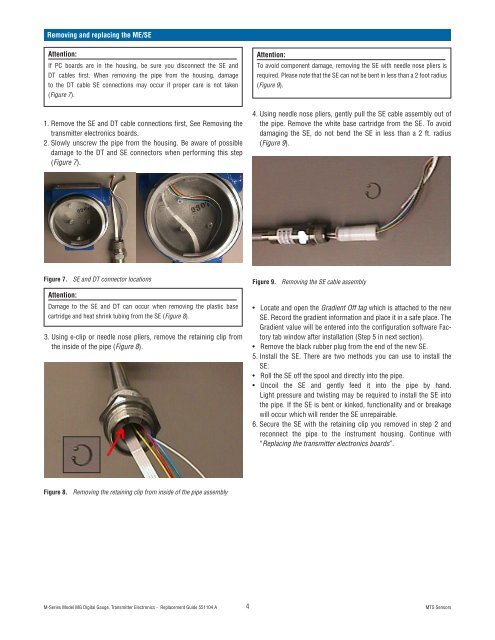
Removing and replacing the ME/SE<br />
Attention:<br />
If PC boards are in the housing, be sure you disconnect the SE and<br />
DT cables first. When removing the pipe from the housing, damage<br />
to the DT cable SE connections may occur if proper care is not taken<br />
(Figure 7).<br />
1. Remove the SE and DT cable connections first, See Removing the<br />
transmitter electronics boards.<br />
2. Slowly unscrew the pipe from the housing. Be aware of possible<br />
damage to the DT and SE connectors when performing this step<br />
(Figure 7).<br />
Figure 7.<br />
Attention:<br />
Damage to the SE and DT can occur when removing the plastic base<br />
cartridge and heat shrink tubing from the SE (Figure 8).<br />
3. Using e-clip or needle nose pliers, remove the retaining clip from<br />
the inside of the pipe (Figure 8).<br />
Figure 8.<br />
SE and DT connector locations<br />
Removing the retaining clip from inside of the pipe assembly<br />
M-Series Model MG Digital Gauge, Transmitter Electronics - Replacement Guide 551104 A 4<br />
Attention:<br />
To avoid component damage, removing the SE with needle nose pliers is<br />
required. Please note that the SE can not be bent in less than a 2 foot radius<br />
(Figure 9).<br />
4. Using needle nose pliers, gently pull the SE cable assembly out of<br />
the pipe. Remove the white base cartridge from the SE. To avoid<br />
damaging the SE, do not bend the SE in less than a 2 ft. radius<br />
(Figure 9).<br />
Figure 9.<br />
Removing the SE cable assembly<br />
• Locate and open the Gradient Off tag which is attached to the new<br />
SE. Record the gradient information and place it in a safe place. The<br />
Gradient value will be entered into the configuration software Factory<br />
tab window after installation (Step 5 in next section).<br />
• Remove the black rubber plug from the end of the new SE.<br />
5. Install the SE. There are two methods you can use to install the<br />
SE:<br />
• Roll the SE off the spool and directly into the pipe.<br />
• Uncoil the SE and gently feed it into the pipe by hand.<br />
Light pressure and twisting may be required to install the SE into<br />
the pipe. If the SE is bent or kinked, functionality and or breakage<br />
will occur which will render the SE unrepairable.<br />
6. Secure the SE with the retaining clip you removed in step 2 and<br />
reconnect the pipe to the instrument housing. Continue with<br />
“Replacing the transmitter electronics boards”.<br />
<strong>MTS</strong> <strong>Sensors</strong>