Level Plus - MTS Sensors
Level Plus - MTS Sensors
Level Plus - MTS Sensors

Create successful ePaper yourself
Turn your PDF publications into a flip-book with our unique Google optimized e-Paper software.
®<br />
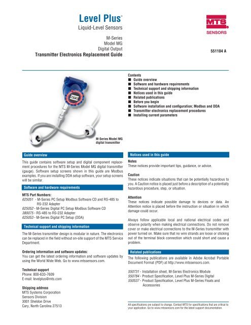
<strong>Level</strong> <strong>Plus</strong><br />
Liquid-<strong>Level</strong> <strong>Sensors</strong><br />
M-Series<br />
Model MG<br />
Digital Output<br />
Transmitter Electronics Replacement Guide<br />
Guide overview<br />
M-Series Model MG<br />
digital transmitter<br />
This guide contains software setup and digital component replacement<br />
procedures for the <strong>MTS</strong> M-Series Model MG digital transmitter<br />
(gauge). Software setup screens shown in this guide are Modbus<br />
examples. If you are installing DDA setup software, your setup screens<br />
will be similar.<br />
Software and hardware requirements<br />
<strong>MTS</strong> Part Numbers:<br />
625051 - M-Series PC Setup Modbus Software CD and RS-485 to<br />
RS-232 Adapter<br />
625052 - M-Series Digital PC Setup Modbus Software CD<br />
380075 - RS-485 to RS-232 Adapter<br />
625053 - M-Series Digital PC Setup (DDA)<br />
Technical support and shipping information<br />
The M-Series transmitter design is modular in nature. The electronics<br />
can be replaced in the field without on-site support of the <strong>MTS</strong> Service<br />
Department.<br />
Ordering information and software updates:<br />
You can get the latest ordering information and software updates by<br />
using the World Wide Web. Go to www.mtssensors.com.<br />
Technical support<br />
Phone: 800-633-7609<br />
E-mail: levelplus@mts.com<br />
Shipping address<br />
<strong>MTS</strong> Systems Corporation<br />
<strong>Sensors</strong> Division<br />
3001 Sheldon Drive<br />
Cary, North Carolina 27513<br />
SENSORS<br />
551104 A<br />
Contents<br />
Guide overview<br />
Software and hardware requirements<br />
Technical support and shipping information<br />
Notices used in this guide<br />
Related publications<br />
Before you begin<br />
Software installation and configuration; Modbus and DDA<br />
Transmitter electronics replacement procedures<br />
Installing current parameters<br />
Notices used in this guide<br />
Notes<br />
These notices provide important tips, guidance, or advice.<br />
Caution<br />
These notices indicate situations that can be potentially hazardous to<br />
you. A Caution notice is placed just before a description of a potentially<br />
hazardous procedure, step, or situation.<br />
Attention<br />
These notices indicate possible damage to devices or data. An<br />
Attention notice is placed before the instruction or situation in which<br />
damage could occur.<br />
Always follow applicable local and national electrical codes and<br />
observe polarity when making electrical connections. Do not remove<br />
cover or make electrical connections to the M-Series transmitter with<br />
power turned on. Make sure that no wire strands are loose or sticking<br />
out of the terminal block connection which could short and cause a<br />
problem.<br />
Related publications<br />
The following publications are available in Adobe Acrobat Portable<br />
Document Format (PDF) at http://www.mtssensors.com.<br />
550731 - Installation sheet, M-Series Electronics Module<br />
550784 - Product Specification, <strong>Level</strong> <strong>Plus</strong> M-Series Digital<br />
550537 - Product Specification, <strong>Level</strong> <strong>Plus</strong> M-Series Floats and<br />
Accessories<br />
All specifications are subject to change. Contact <strong>MTS</strong> for specifications that are critical to<br />
your application. Go to www.mtssensors.com for the latest support documentation.
Before you begin<br />
Before replacing your digital transmitter electronics, make sure that it<br />
is programmed with the transmitter data restore file you created after<br />
initial installation and calibration of your transmitter.<br />
Note:<br />
Each transmitter requires its own restore file.<br />
• To install the transmitter setup software, go to the section titled<br />
“Software installation and configuration; Modbus and DDA”.<br />
• To create a restore file, go to the section titled “ Create the transmitter<br />
data restore file”.<br />
• If your transmitter electronics PCB is already programmed and you<br />
have a data restore file, go to the section titled “Replacing your<br />
transmitter electronics PCB”.<br />
Software installation and configuration; Modbus and DDA<br />
Obtain the setup software that shipped with your transmitter or go to<br />
www.mtssensors.com and download the latest Modbus or DDA setup<br />
software from the <strong>MTS</strong> software Vault. You will be asked to register<br />
for a login and password to enter the Vault portal. From the Vault, do<br />
the following:<br />
For Modbus configuration, download Modbus_*.zip<br />
For DDA configuration, download DDA_*.zip<br />
Perform the following steps to extract and install the setup software:<br />
1. Locate and double-click the appropriate protocol_*.zip file. Extract<br />
the program folder into C:\ProgramFiles\ and double-click the *.exe<br />
file to install the program.<br />
2. Create shortcut and Enable factory mode: Go to C:\ProgramFiles\<strong>MTS</strong><br />
<strong>Sensors</strong>\ and right click the program configuration folder. Drag the<br />
folder to your desktop.<br />
3. Right click the Configuration folder shortcut icon, select “ Properties”.<br />
The shortcut properties dialog box opens (Figure 1).<br />
Figure 1.<br />
Shortcut creation and Target entry<br />
M-Series Model MG Digital Gauge, Transmitter Electronics - Replacement Guide 551104 A<br />
2<br />
In the “Target” entry box at the end of the path string, type Spacebar/F:1.<br />
The string should resemble one of the following:<br />
“C:\ProgramFiles\<strong>MTS</strong><strong>Sensors</strong>\ModbusConfig\ModbusConfig.exe”/F:1<br />
“C:\ProgramFiles\<strong>MTS</strong><strong>Sensors</strong>\DDAConfig\DDAConfig.exe”/F:1<br />
4. Continue with “ Create the transmitter data restore file”.<br />
Create the transmitter data restore file<br />
Note:<br />
Each transmitter requires its own restore file. Your transmitter must be<br />
installed properly and calibrated before you create the data restore file.<br />
Perform the following steps to create a transmitter data restore file:<br />
1. Click the program file icon to launch the configuration setup<br />
software. The setup “Configuration” window opens (Figure 2).<br />
Figure 2.<br />
Shortcut creation and Target entry<br />
2. Connect the transmitter. If the transmitter is connected properly,<br />
you will see five new tab selections at the top of the window.<br />
perform the following:<br />
a. Click the “ Data from Device” tab, a new window opens.<br />
b. Click the “ Backup/Restore” button. a new window opens.<br />
c. Click the “ Get Data from Sensor” button, then select the<br />
“Save settings to file” button.<br />
d. Type in a filename such as ModbusRestore or DDARestore<br />
and path that you can easily locate. then, click “Save”<br />
<strong>MTS</strong> <strong>Sensors</strong>
Transmitter electronics replacement procedure<br />
Complete the following steps to remove and replace your transmitter<br />
electronics board after you have successfully created a data restore<br />
file.<br />
Caution:<br />
Ensure that all power is disconnected and that all lockout procedure(s) are<br />
followed prior to opening the transmitter instrument housing.<br />
Removing the transmitter electronics boards<br />
1. Remove any dirt, debris, or liquid from the top of the instrument<br />
enclosure.<br />
2. Remove the instrument housing cover.<br />
3. Remove wired connector (replacement included if needed) from PC<br />
board terminal block (Figure 3).<br />
Figure 3.<br />
Transmitter electronics top board with connector removed<br />
4. Remove the existing transmitter electronics by unscrewing the four<br />
retaining screws and removing the (top) board. Note the orientation<br />
of boards housing before removal to aid in installation of replacement<br />
boards (Figure 4).<br />
Figure 4.<br />
Top electronics board retaining screw locations<br />
3<br />
5. Unscrew four standoffs and remove bottom board ( Figure 5).<br />
Figure 5.<br />
Bottom electronics board standoffs locations<br />
6. Disconnect the white sensing element (SE) 6-pin connector from<br />
the bottom board (pull straight out) and remove the white DT ribbon<br />
cable connector with a small green connector card if present (slide<br />
wing outward and pull connector out parallel to the PCB sideways)<br />
(Figure 6).<br />
DT connector<br />
with green board<br />
SE connector<br />
Figure 6.<br />
SE and DT connector locations<br />
Replacing the transmitter electronics boards<br />
Use the same procedure and adhere to the same cautions noted in the<br />
board removal process when reinstalling boards. Install the boards in<br />
the following order:<br />
1. Reconnect the sensing element (SE) connector and DT connector<br />
(when available). Before you reconnect the DT to the board, verify<br />
that the gold DT connector pins are facing down. Push wing back in<br />
lock the DT cable.<br />
2. Install the new base board (round edges) with four standoffs<br />
(replacement standoffs included).<br />
3. Install top board and secure with four screws (replacement screws<br />
are included with kit). Verify that the orientation of the boards<br />
are such that the connectors are all located on the same side as in<br />
(Figure 4).<br />
4. Plug the wired connector into the PC board terminal block.<br />
5. Reattach the transmitter instrument housing cover.<br />
<strong>MTS</strong> <strong>Sensors</strong> M-Series Model MG Digital Gauge, Transmitter Electronics - Replacement Guide 551104 A
Removing and replacing the ME/SE<br />
Attention:<br />
If PC boards are in the housing, be sure you disconnect the SE and<br />
DT cables first. When removing the pipe from the housing, damage<br />
to the DT cable SE connections may occur if proper care is not taken<br />
(Figure 7).<br />
1. Remove the SE and DT cable connections first, See Removing the<br />
transmitter electronics boards.<br />
2. Slowly unscrew the pipe from the housing. Be aware of possible<br />
damage to the DT and SE connectors when performing this step<br />
(Figure 7).<br />
Figure 7.<br />
Attention:<br />
Damage to the SE and DT can occur when removing the plastic base<br />
cartridge and heat shrink tubing from the SE (Figure 8).<br />
3. Using e-clip or needle nose pliers, remove the retaining clip from<br />
the inside of the pipe (Figure 8).<br />
Figure 8.<br />
SE and DT connector locations<br />
Removing the retaining clip from inside of the pipe assembly<br />
M-Series Model MG Digital Gauge, Transmitter Electronics - Replacement Guide 551104 A 4<br />
Attention:<br />
To avoid component damage, removing the SE with needle nose pliers is<br />
required. Please note that the SE can not be bent in less than a 2 foot radius<br />
(Figure 9).<br />
4. Using needle nose pliers, gently pull the SE cable assembly out of<br />
the pipe. Remove the white base cartridge from the SE. To avoid<br />
damaging the SE, do not bend the SE in less than a 2 ft. radius<br />
(Figure 9).<br />
Figure 9.<br />
Removing the SE cable assembly<br />
• Locate and open the Gradient Off tag which is attached to the new<br />
SE. Record the gradient information and place it in a safe place. The<br />
Gradient value will be entered into the configuration software Factory<br />
tab window after installation (Step 5 in next section).<br />
• Remove the black rubber plug from the end of the new SE.<br />
5. Install the SE. There are two methods you can use to install the<br />
SE:<br />
• Roll the SE off the spool and directly into the pipe.<br />
• Uncoil the SE and gently feed it into the pipe by hand.<br />
Light pressure and twisting may be required to install the SE into<br />
the pipe. If the SE is bent or kinked, functionality and or breakage<br />
will occur which will render the SE unrepairable.<br />
6. Secure the SE with the retaining clip you removed in step 2 and<br />
reconnect the pipe to the instrument housing. Continue with<br />
“Replacing the transmitter electronics boards”.<br />
<strong>MTS</strong> <strong>Sensors</strong>
Installing current parameters<br />
Setting new gradient value and board parameters<br />
Your new boards must be programmed before use. Follow the steps<br />
below to program your new boards:<br />
1. Launch your setup software and connect to the transmitter. Click<br />
the “Data from Device” tab, then click the “Backup/Restore” button.<br />
The “Backup and Restore Device Settings” window opens (Figure<br />
10).<br />
Figure 10. Data from Device window; Backup and restore settings.<br />
2. Click the “ Read Settings from file” button. Then, select your previously<br />
saved data restore file.<br />
3. Click the “ Write Data to Sensor” button, Click “Yes”, Click “OK” and<br />
“Close”.<br />
4. Click the “ Factory” tab. The Factory Tab window opens. Type the<br />
Gradient value you recorded from the Gradient Off Tag (Figure 11).<br />
Figure 11. Factory window; Entering the new gradient value and reading<br />
new settings<br />
5<br />
5. Click “ Read”.<br />
6. Click the “ Volume” tab. The Volume tab window opens. Click ”Strap<br />
table”.<br />
7. Click “ Read from Table”. Then, click “Write data to sensor”.<br />
8. You will be prompted for a password. The password is “ becareful”.<br />
<strong>MTS</strong> <strong>Sensors</strong> M-Series Model MG Digital Gauge, Transmitter Electronics - Replacement Guide 551104 A
SENSORS<br />
UNITED STATES<br />
<strong>MTS</strong> Systems Corporation<br />
<strong>Sensors</strong> Division<br />
3001 Sheldon Drive<br />
Cary, NC 27513<br />
Tel: (800) 457-6620<br />
Fax: (919) 677-2545<br />
(800) 943-1145<br />
www.mtssensors.com<br />
sensorsinfo@mts.com<br />
Part Number: 11-07 551104 Revision A<br />
<strong>MTS</strong>, Temposonics and <strong>Level</strong> <strong>Plus</strong> are registered trademarks of <strong>MTS</strong> Systems Corporation.<br />
All other trademarks are the property of their respective owners.<br />
All Temposonics sensors are covered by US patent number 5,545,984. Additional patents are pending.<br />
Printed in USA. Copyright © 2007 <strong>MTS</strong> Systems Corporation. All Rights Reserved in all media.<br />
GERMANY<br />
<strong>MTS</strong> Sensor Technologie<br />
GmbH & Co. KG<br />
Auf dem Schüffel 9<br />
D - 58513 Lüdenscheid<br />
Tel: +49 / 23 51 / 95 87-0<br />
Fax: +49 / 23 51 / 56 491<br />
www.mtssensor.de<br />
info@mtssensor.de<br />
JAPAN<br />
<strong>MTS</strong> <strong>Sensors</strong> Technology<br />
Corporation<br />
Ushikubo Bldg.<br />
737 Aihara-cho, Machida-shi<br />
Tokyo 194-0211, Japan<br />
Tel: +81 (42) 775 / 3838<br />
Fax: +81 (42) 775 / 5516<br />
www.mtssensor.co.jp<br />
info@mtssensor.co.jp