impulse-ed 2-060417

Create successful ePaper yourself
Turn your PDF publications into a flip-book with our unique Google optimized e-Paper software.
IMPULSE 2017<br />
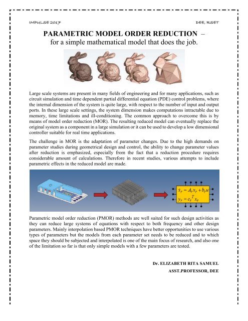
PARAMETRIC MODEL ORDER REDUCTION –<br />
for a simple mathematical model that does the job.<br />
DEE, RSET<br />
Large scale systems are present in many fields of engineering and for many applications, such as<br />
circuit simulation and time dependent partial differential equation (PDE) control problems, where<br />
the internal dimension of the system is quite large, with respect to the number of input and output<br />
ports. In these large scale settings, the system dimension makes computations intractable due to<br />
memory, time limitations and ill-conditioning. The common approach to overcome this is by<br />
means of model order r<strong>ed</strong>uction (MOR). The resulting r<strong>ed</strong>uc<strong>ed</strong> model can eventually replace the<br />
original system as a component in a large simulation or it can be us<strong>ed</strong> to develop a low dimensional<br />
controller suitable for real time applications.<br />
The challenge in MOR is the adaptation of parameter changes. Due to the high demands on<br />
parameter studies during geometrical design and control, the ability to change parameter values<br />
after r<strong>ed</strong>uction is emphasiz<strong>ed</strong>, especially from the fact that a r<strong>ed</strong>uction proc<strong>ed</strong>ure requires<br />
considerable amount of calculations. Therefore in recent studies, various attempts to include<br />
parametric effects in the r<strong>ed</strong>uc<strong>ed</strong> model are made.<br />
Parametric model order r<strong>ed</strong>uction (PMOR) methods are well suit<strong>ed</strong> for such design activities as<br />
they can r<strong>ed</strong>uce large systems of equations with respect to both frequency and other design<br />
parameters. Mainly interpolation bas<strong>ed</strong> PMOR techniques have better opportunities to use various<br />
types of parameters but the models from each parameter set ne<strong>ed</strong>s to be r<strong>ed</strong>uc<strong>ed</strong> and to which<br />
space they should be subject<strong>ed</strong> and interpolat<strong>ed</strong> is one of the main focus of research, and also one<br />
of the limitation so far is that only simple models with a few parameters are test<strong>ed</strong>.<br />
Dr. ELIZABETH RITA SAMUEL<br />
ASST.PROFESSOR, DEE
IMPULSE 2017<br />
DEE, RSET<br />
ELECTRIC SPRING (ES) - A PROMISING SMART GRID<br />
TECHNOLOGY<br />
Most PV systems are set up to disconnect from the grid whenever they detect a significant fault.<br />
If a single home’s PV system trips off-line, it’s only a headache for the owner. But if hundr<strong>ed</strong>s or<br />
thousands of them do so simultaneously, it could upset the network’s delicate balance, turning an<br />
otherwise small disturbance into an outage blacking out an entire city or county. Throughout much<br />
of the develop<strong>ed</strong> world, electric utilities are facing an unprec<strong>ed</strong>ent<strong>ed</strong> challenge. Growing numbers<br />
of customers are installing solar PV systems on their homes or businesses. The power they’re<br />
injecting into distribution lines is causing voltage- and frequency-control problems that threaten<br />
to destabilize the grid. While this is not yet a major problem, it could become one as distribut<strong>ed</strong><br />
solar systems proliferate. The cause of the problem is the inverter, an electronic system that<br />
converts the direct current (DC) suppli<strong>ed</strong> by the PV panels into the alternating current (AC) that<br />
flows on the power grid. Although they supply AC at the right voltage and frequency to sync with<br />
the distribution grid, they are otherwise passive. They can’t sense what is happening on the grid<br />
and adjust themselves accordingly. But newer “smart” inverters can prevent a PV system from<br />
going off-line when it doesn’t have to. By doing so, they can actually make the grid more stable,<br />
by preventing the sudden deterioration of voltage and frequency that would otherwise occur when<br />
hundr<strong>ed</strong>s or thousands of PV panels are suddenly taken off-line.<br />
Smart inverters are pois<strong>ed</strong> to fill a big ne<strong>ed</strong> in the fast-evolving electric-utility industry. As more<br />
and more homeowners put PV panels on their roofs, the power they are supplying is r<strong>ed</strong>ucing the<br />
ne<strong>ed</strong> for big, centraliz<strong>ed</strong> generating plants. The upshot is that increasing numbers of these<br />
traditional power plants are getting retir<strong>ed</strong>, and grid operators are scrambling for ways to keep<br />
their networks running with the same high level of reliability that their customers have long taken<br />
for grant<strong>ed</strong>. The combination of smart inverters and new control methods will be essential for<br />
helping utilities transition to the grid of the future, in which vast amounts of wind- and solargenerat<strong>ed</strong><br />
electricity will be the norm. A smart inverter can “ride through” voltage or frequency<br />
dips and other short-term grid disturbances and if these inverters have communications<br />
capabilities, they can let grid operators monitor and control them in response to changing<br />
conditions.<br />
The power grids of the future may ne<strong>ed</strong> advanc<strong>ed</strong> inverters that don’t simply follow what the grid<br />
is doing but actually help form the grid, by responding instantaneously to disturbances and working<br />
in concert to help keep the grid stable. This approach, known as Virtual Oscillator Control (VOC),<br />
was develop<strong>ed</strong> by an NREL team l<strong>ed</strong> by Brian Johnson working with Sairaj Dhople of the<br />
University of Minnesota; Francesco Bullo at the University of California, Santa Barbara; and<br />
Florian Dörfler at ETH Zurich.<br />
The basic idea behind VOC is to leverage the properties of oscillators—that is, anything that moves<br />
in a periodic fashion, such as a mechanical spring, a metronome, or a motor. When two oscillators<br />
are pair<strong>ed</strong>, or coupl<strong>ed</strong>, their motions will naturally align and picture several weights hanging from<br />
springs that are connect<strong>ed</strong> to a rigid and fix<strong>ed</strong> board. As the weights are given a pull to set the<br />
springs bouncing, the springs will tend to bounce in an uncoordinat<strong>ed</strong> fashion. However, if the<br />
board itself is suspend<strong>ed</strong> from the ceiling on springs, it becomes a fe<strong>ed</strong>back mechanism that<br />
responds inversely to the pushes and pulls from the bouncing weights. Within a short period of<br />
time, the weights will all start bouncing at the same frequency, all in lockstep.
IMPULSE 2017<br />
DEE, RSET<br />
For virtual oscillator control, the trick is to make each inverter respond to the grid much like a<br />
spring: If the grid voltage drops, the inverter adjusts its output such that it “pushes” against the<br />
voltage change. Likewise, a surge in grid voltage will induce an inverter to “pull” the voltage back<br />
to the nominal range. An increase or decrease in grid frequency will similarly cause the inverter to<br />
adjust its power output to compensate. The use of “Electric Springs” is a novel way of distribut<strong>ed</strong><br />
voltage control while simultaneously achieving effective Demand-Side Management (DSM)<br />
through modulation of noncritical loads in response to the fluctuations in intermittent renewable<br />
energy sources like Wind, solar etc. The role of demand side management is going to be critical<br />
once the penetration of renewable energy sources becomes significant. This would bring about a<br />
paradigm shift from the traditional centraliz<strong>ed</strong> control of hundr<strong>ed</strong>s of power plants to match the<br />
demand to decentraliz<strong>ed</strong> control of millions of loads to balance the supply (generation). In a<br />
distribution network, uncertainty and variability associat<strong>ed</strong> with renewable energy sources, such<br />
as solar power and wind power, can easily cause power fluctuations, voltage instability and<br />
frequency deviations. In recent years, Electric Springs (ESs) have been develop<strong>ed</strong> as a new means<br />
of addressing these issues. Besides regulating ac voltages in the distribution network, ESs can also<br />
regulate the load power flow to response the variable renewable sources. Therefore, it brings a<br />
new control paradigm, i.e., the load demand following variable power generation.<br />
An ES connect<strong>ed</strong> in series with the noncritical load (e.g., a water heater) that has high voltage<br />
variation tolerance forms the so-call<strong>ed</strong> smart load. The critical load that requires a well-regulat<strong>ed</strong><br />
mains voltage is parallel with the smart load branch. By operating under inductive or capacitive<br />
mode, the ES can inject a controllable voltage and accordingly change the uncritical load voltage<br />
so as to maintain the voltage across the smart load at a constant level. In addition, it also enables<br />
uncritical load to vary its power consumption and thus contributes to the demand response.<br />
Overall, the smart load can be intend<strong>ed</strong> to provide reactive power compensation to the system by<br />
adjusting the output voltage of ES and ensure a tightly regulat<strong>ed</strong> voltage across the critical load.<br />
So far, three generations of ESs have been develop<strong>ed</strong>. The first generation, consisting of a singlephase<br />
inverter with a capacitor install<strong>ed</strong> on the dc-link side, is connect<strong>ed</strong> in series with a noncritical<br />
load and drawback is its limit<strong>ed</strong> reactive power compensation capability. The second<br />
generation is propos<strong>ed</strong> and it replaces the capacitor with a battery, which enables the active power<br />
regulation. However, the battery brings other problems such as larger size, shorter service life and<br />
higher cost. The third generation solves the battery problem using two bidirectional inverters<br />
connect<strong>ed</strong> back-to-back through a dc bus, but additional transformers are requir<strong>ed</strong> to isolate the<br />
inverters from the grid. It is expect<strong>ed</strong> that the ES, as a decentraliz<strong>ed</strong> approach, can also be us<strong>ed</strong> to<br />
improve the power quality of the distribution (low-voltage) power grids. Conventionally, single<br />
centraliz<strong>ed</strong> techniques such as the series and shunt VAR compensators are us<strong>ed</strong> at the high voltage<br />
level to improve the performance of AC power systems by providing 1) load compensation and 2)<br />
voltage support.<br />
There is a growing interest in using dc power systems and micro grids for our electricity<br />
transmission and distribution, particularly with the increasing penetration of photovoltaic power<br />
systems. ES’s Dispers<strong>ed</strong> throughout the distribution system can provide a strong and cost effective<br />
mechanism for distribut<strong>ed</strong> voltage control that emerg<strong>ed</strong> as a novel way of DSM on the real time<br />
basis.<br />
Ms. PRATHIBHA P.K.<br />
ASST.PROFESSOR, DEE
IMPULSE 2017<br />
DEE, RSET<br />
INTEGRATION OF SC METHODOLOGIES WITH<br />
Fundamentals of SMC<br />
SLIDING MODE CONTROL<br />
The SMC theory was originat<strong>ed</strong> in late 1950s in the former USSR, l<strong>ed</strong> by Prof. V. I. Utkin and<br />
Prof. S. V. Emelyanov [2] to address specific problems associat<strong>ed</strong> with a special class of VSSs,<br />
which are the control systems involving discontinuous control actions.<br />
In the early days of VSS, the research was focus<strong>ed</strong> on single-input and single-output systems, and<br />
various well-known methodologies were develop<strong>ed</strong>, e.g., the eigen value assignment approach [2],<br />
the Fillipov approach [5], etc. In recent years, the majority of research in SMC has been done with<br />
regard to multiinput and multioutput systems (MIMO), so we will use MIMO system framework<br />
as a platform for discussing the integration of SC methodologies in SMC. Commonly, the MIMO<br />
SMC systems consider<strong>ed</strong> are of the form<br />
ẋ˙ = f(x, t) + B(x, t)u + ξ(x, t)<br />
where<br />
x ∈ R n u is the system state vector and ξ(x, t) ∈ Rn represents all the factors that affect the<br />
performance of the control system, such as disturbances and uncertainties in the parameters of the<br />
system.<br />
.It is well known that when this condition (the matching condition) is satisfi<strong>ed</strong>, the celebrat<strong>ed</strong><br />
invariance property of SMC stands.<br />
The design proc<strong>ed</strong>ure of SMC includes two major steps encompassing two main phases of SMC:<br />
1) Reaching phase: where the system state is driven from any initial state to reach the switching<br />
manifolds (the anticipat<strong>ed</strong> sliding modes) in finite time;<br />
2) Sliding-mode phase: where the system is induc<strong>ed</strong> into the sliding motion on the switching<br />
manifolds, i.e., the switching manifolds become an attractor. These two phases correspond to the<br />
following two main design steps.<br />
1) Switching manifold selection: A set of switching manifolds are select<strong>ed</strong> with prescrib<strong>ed</strong><br />
desirable dynamical characteristics. Common candidates are linear hyper-planes.<br />
2) Discontinuous control design: A discontinuous control strategy is form<strong>ed</strong> to ensure the finite<br />
time reachability of the switching manifolds. The controller may be either local or global,<br />
depending upon specific control requirements.<br />
In the context of the system (1), following the main SMC design steps, the switching manifolds<br />
can be denot<strong>ed</strong> as<br />
s(x) = 0 ∈ Rm, where s = (s1, . . . , sm)T<br />
is characteriz<strong>ed</strong> by the control structure defin<strong>ed</strong> by
IMPULSE 2017<br />
DEE, RSET<br />
.<br />
According to the SMC theory, when the sliding mode occurs, a so-call<strong>ed</strong> “equivalent control” is<br />
induc<strong>ed</strong>, i.e.,̇<br />
Without loss of generality, we assume that<br />
is nonsingular. It is commonly<br />
understood that in the sliding mode, there exists a virtual control signal<br />
which drives the system dynamics resulting in<br />
SMC Design Methods<br />
There are several SMC controller types seen in the literature, which one to use is dependent upon<br />
the specific problems to be dealt with. However, central to the SMC design is the use of the<br />
Lyapunov stability theory, in which the Lyapunov function of the form<br />
is commonly taken. The control design task then becomes to find a suitable<br />
discontinuous control such that V< 0 in the neighborhood of the equilibrium.<br />
If one would like to emb<strong>ed</strong> learning and adaptation in SMC to enhance its performance, one<br />
common alternative Lyapunov function may be construct<strong>ed</strong> as<br />
where R and Q are symmetric nonnegative definite matrices of appropriate dimensions.<br />
Typical SMC strategies for MIMO systems include the following.<br />
1) Equivalent control-bas<strong>ed</strong> SMC. This is a control of the type<br />
Where u s is a switching control component which may have two types of switching<br />
and there are other variants.<br />
2) Bang-bang-type SMC: This is a control of direct switching type
̇<br />
IMPULSE 2017<br />
DEE, RSET<br />
should be large enough to suppress all bound<strong>ed</strong> uncertainties and unstructur<strong>ed</strong> systems dynamics.<br />
Design of such control relies on the Fillipov method, by which, a sufficient large local attraction<br />
region is creat<strong>ed</strong> to suck in all system trajectories.<br />
3) Enforce<br />
to realize finite time reachability, where R>0 and K>0 are diagonal matrices and<br />
Key Issues in SMC Theory and Applications<br />
There are several key issues that are commonly seen as obstacles affecting the wide spread<br />
applications of SMC, which have prompt<strong>ed</strong> the extensive use of SC and other technologies<br />
in SMC systems in recent years. Some of these are list<strong>ed</strong> in the following.<br />
1) Chattering:<br />
As has been previously mention<strong>ed</strong>, SMC is a special class of VSSs, in which the sliding modes<br />
are induc<strong>ed</strong> by disruptive control forces. As demonstrat<strong>ed</strong> in the previous sections, despite the<br />
advantages of simplicity and robustness, SMC generally suffers from the well-known problem,<br />
namely,chattering , which is a motion oscillating around the pr<strong>ed</strong>efin<strong>ed</strong> switching manifold(s).<br />
Two causes are commonly conceiv<strong>ed</strong>.<br />
1. The presence of parasitic dynamics in series with the control systems causes a smallamplitude<br />
high-frequency oscillation. These parasitic dynamics represent the fast actuator<br />
and sensor dynamics which are normally neglect<strong>ed</strong> during the control design.<br />
2. The switching non idealities can cause high-frequency oscillations. These may include<br />
small time delays due to sampling [e.g., zero-order hold (ZOH)], and/or execution time<br />
requir<strong>ed</strong> for calculation of control, and more recently, transmission delays in network<strong>ed</strong><br />
control systems.<br />
Various methods have been propos<strong>ed</strong> to “soften” the chattering. Examples are as follow.<br />
1. The boundary layer control in which the sign function is replac<strong>ed</strong> by which could be a<br />
constant or a function of states as well.<br />
2. The continuous approximation method in which the sign function is replac<strong>ed</strong> by a<br />
continuous approximation<br />
Where ε is a small positive number<br />
This, in fact, gives rise to a high-gain control when the states are in the close neighborhood<br />
of the switching manifold.<br />
2) Match<strong>ed</strong> and Unmatch<strong>ed</strong> Uncertainties:<br />
It is known that the celebrat<strong>ed</strong> invariance property of SMC lies in its insensitivity to match<strong>ed</strong><br />
uncertainties when in the sliding mode. However, if the matching condition is not satisfi<strong>ed</strong>,<br />
the sliding mode (motion) is dependent on the uncertainties ξ which is not desirable because<br />
the condition for the well-known robustness of SMC does not hold. Research efforts in this
IMPULSE 2017<br />
DEE, RSET<br />
aspect have been focus<strong>ed</strong> on restricting the influence of the uncertainties ξ within a desir<strong>ed</strong><br />
bound.<br />
3) Unmodel<strong>ed</strong> Dynamics:<br />
Mathematically, it is impossible to model a practical system perfectly. There always exists<br />
some unmodel<strong>ed</strong> dynamics. The situation may be worsen<strong>ed</strong> if the unmodel<strong>ed</strong> dynamics contains<br />
high-frequency oscillatory dynamics which may be excit<strong>ed</strong> by the high-frequency control<br />
switching of SMC. There are several aspects of dealing with this unmodel<strong>ed</strong> dynamics.<br />
More broadly, in the complex systems environment, the object to be controll<strong>ed</strong> is difficult to model<br />
without a significant increase in the dimensions of the problem space. Often, it is more feasible to<br />
study the component subsystems link<strong>ed</strong> through aggregation. The challenge is how to design an<br />
effective SMC without knowing the dynamics of the entire system (apart from the aggregative<br />
links and local models). This research topic has been very popular in recent years in the intelligent<br />
control community using, for example, NNs, FL, and PR,where PR technology is being focus<strong>ed</strong><br />
here.<br />
SC TECHNOLOGIES<br />
In this section, some brief introduction to the key SC techniques which are commonly us<strong>ed</strong> in<br />
dynamical systems and control. Components of SC technologies are NNs, FL, and PR which<br />
subsume belief networks, evolutionary computation (EC), chaos theory, and parts of learning<br />
theory.<br />
PR refers to EC, chaos theory, belief networks, and parts of learning theory. Below are some brief<br />
overviews of the area.<br />
Among PR technologies, EC techniques have been a most widely us<strong>ed</strong> technology for optimization<br />
in SMC. The EC paradigm attempts to mimic the evolution processes observ<strong>ed</strong> in nature and utilize<br />
them for solving a wide range of optimization problems. EC technologies include genetic<br />
algorithms (GAs), genetic programming, evolutionary algorithms, and strategies. In general, EC<br />
performs direct<strong>ed</strong> random searches using mutation and/or crossover operations through evolving<br />
populations of solutions with the aim of finding the best solutions (the fittest survives). The<br />
criterion which is express<strong>ed</strong> in terms of an objective function, is usually referr<strong>ed</strong> to as a fitness<br />
function.<br />
INTEGRATION OF SC METHODOLOGIES<br />
The aforemention<strong>ed</strong> SC paradigms offer different advantages. The integration of these paradigms<br />
would give rise to powerful tools for solving difficult practical problems. It should be not<strong>ed</strong> that<br />
NNs and EC are about a process that enables learning and optimization while the FL systems are<br />
a representation tool. Emerging technologies such as swarm optimization, chaos theory, and<br />
complex network theory also provide alternative tools for optimization and for explaining<br />
emerging behaviors which are pr<strong>ed</strong>ict<strong>ed</strong> to be widely us<strong>ed</strong> in the future.<br />
SMC WITH SC<br />
There has been extensive research done in using SC technologies for SMC systems. An earlier<br />
survey already out-lin<strong>ed</strong> some of the major developments. Since then, significant research has
IMPULSE 2017<br />
DEE, RSET<br />
been progress<strong>ed</strong> and this paper aims to depict the state of the art of SMC with SC. We will use<br />
the same categories as in Section III to summarize the developments.<br />
As has been stat<strong>ed</strong> before, the integration of SMC and SC has two dimensions. One is the<br />
application of SC technologies in SMC to make it “smarter” and the other using SMC to enhance<br />
SC capabilities. This survey will be confin<strong>ed</strong> within the scope of the former, i.e., the application<br />
of SC technologies in SMC.<br />
SMC WITH PR<br />
One PR technology commonly us<strong>ed</strong> in SMC is the EC for optimization. Another area is the<br />
application of chaos theory in SMC. We shall discuss their applications in SMC in the following.<br />
SMC WITH EC:<br />
The optimization of the control parameters and the model parameters are vitally important in<br />
r<strong>ed</strong>ucing chattering and improving robustness. In this respect, various optimization techniques can<br />
be us<strong>ed</strong> such as the gradient-bas<strong>ed</strong> search, Levenberg–Marquart algorithm, etc.; however, a<br />
significant amount of information about the tendency of search parameters toward optima (i.e., the<br />
derivative information) is requir<strong>ed</strong>. The complexity of the problem and the sheer number of<br />
parameters make the application of the conventional search methods rather hard. The key process<br />
of using EC is to treat the set of parameters (often a large number) as the attributes of an individual<br />
in a population and generate enough number of individuals randomly to ensure a rich diversity of<br />
“genes” in the population, through bio inspir<strong>ed</strong> operations such as mutation and/or crossover. The<br />
advantages previously mention<strong>ed</strong> has motivat<strong>ed</strong> various researchers to use EC as an alternative to<br />
find “optimal” solutions for SMC.<br />
SMC with Integrat<strong>ed</strong> NN, FL, and EC<br />
It is recogniz<strong>ed</strong> that NNs and EC are processes that enable learning and optimization while the<br />
fuzzy systems are a representation tool .For complex systems which are difficult to model and<br />
represent in an analytic form, it is certainly advantageous to use fuzzy systems as a paradigm to<br />
represent the complex systems as an aggregat<strong>ed</strong> set of simpler models, just like the role of local<br />
linearization plays in nonlinear function approximation by piecing together locally lineariz<strong>ed</strong><br />
models. NNs on the other hand can be us<strong>ed</strong> as a learning mechanism to learn the dynamics while<br />
the EC approaches can be us<strong>ed</strong> to optimize the representation and learning. Such ideas have been<br />
us<strong>ed</strong> quite extensively in dynamic systems and control areas. Research works in this area include<br />
two fuzzy NNs are us<strong>ed</strong> to learn the control as well as identify the uncertainties to eliminate<br />
chattering in distribut<strong>ed</strong> control systems. The conventional BP-bas<strong>ed</strong> learning mechanism can be<br />
employ<strong>ed</strong> for learning.<br />
Ms. RINU ALICE KOSHY<br />
ASST.PROFESSOR, DEE
IMPULSE 2017<br />
DEE, RSET<br />
ENERGY STORAGE TECHNOLOGIES & THEIR ROLE<br />
IN RENEWABLE INTEGRATION<br />
1. Short Introduction to the Electric Grid<br />
The amount of electricity produc<strong>ed</strong> must always be on the same level as demand. Unfortunately<br />
the demand keeps changing from throughout the year and through the day too (Fig 1).<br />
Fig 1: Load curves for typical electrical grid<br />
In addition to this most renewable energy sources have a fluctuating output.So an efficient storage<br />
of energy is essential. They balance out fluctuations of renewable energies.<br />
2. Energy Storage Technologies<br />
2.1 Flywheels<br />
Flywheels store energy in form of kinetic energy in a rotating hub. Low maintenance and long<br />
lifespan, no carbon emissions, Fast Response times and N o toxic components are its advantages<br />
and its disadvantages are high acquisition costs, low storage Capacity and High self discharge (2-<br />
20 % per hour)<br />
Fig 2: Fly wheels<br />
2.2 Superconducting Magnetic Energy Storage (SMES)<br />
A SMES system stores energy in form of an electromagnetic field surrounding the coil.
IMPULSE 2017<br />
DEE, RSET<br />
Fig 3: SMES Components<br />
Most superconducting coils are wound using conductors which are compris<strong>ed</strong> of many fine<br />
filaments of a niobium-titanium (NbTi) alloy emb<strong>ed</strong>d<strong>ed</strong> in a copper matrix. The Size of the coil<br />
depends upon the energy storage requirement and coil geometry. The power conditioning system<br />
is an Interface between the superconducting magnet and AC power system. The cryogenic units<br />
maintain a temperature of about 4.5 K. The control system controls the power flow from the<br />
renewable device to the storage system and also controls the flow to the grid. Fast responses,<br />
capability of partial and deep discharges, environmentally safe are its advantages. The system is<br />
very expensive and of poor efficiency. It also has high energy losses (∼ 12% per day)<br />
2.3 Batteries<br />
Batteries store energy in chemical form. Most battery technologies use two different compounds<br />
which release energy in form of an electrical current when reacting with each other. It has high<br />
potential for improvements. The main drawback is its limit<strong>ed</strong> life cycle and require a lot of<br />
resources for production.<br />
2.4 Pump<strong>ed</strong> Storage Hydroelectricity (PSH)<br />
In a PSH electrical power<strong>ed</strong> turbines pump water into higher reservoirs. When ne<strong>ed</strong><strong>ed</strong>, the water<br />
flows back down and power the revers<strong>ed</strong> turbines. PSH is capable of storing huge amounts of<br />
energy. High efficiency, fast response time and cheap makes it ideal for storage. Availability of<br />
water is essential for its operation. Environmental impacts are of concern.
IMPULSE 2017<br />
DEE, RSET<br />
2.5 Compress<strong>ed</strong> Air Energy Storage (CAES)<br />
Fig 4: PSH<br />
CAES plants store energy in form of compress<strong>ed</strong> air in underground caverns. The Advanc<strong>ed</strong><br />
Adiabatic (AA) CAES stores the heat produc<strong>ed</strong> during the compression and compensates the<br />
freezing during the expansion.<br />
Fig 5: CAES<br />
This technology is capable of storing huge amounts of energy with high efficiencies. It has fast<br />
response time and inexpensive too. The disadvantage is that it is economical for storage for a short<br />
time.<br />
3. Summary / Conclusion<br />
PSH currently the only viable solution, Flywheels, SMES and batteries possess small potential,<br />
CAES shows the greatest potential.<br />
Dr. UNNIKRISHNAN P.C.<br />
PROFESSOR, DEE
IMPULSE 2017<br />
BROADBAND FOR TRANSPORTATION<br />
----HYPERLOOP<br />
DEE, RSET<br />
Conventional means of transportation (road, water, air, and rail) tend to be some mix of expensive,<br />
slow, and environmentally harmful. Road travel is particularly problematic, given carbon<br />
emissions and the fluctuating price of oil. Rail travel is relatively energy efficient and offers the<br />
most environmentally friendly option, but is too slow and expensive to be massively adopt<strong>ed</strong>.<br />
Given these issues, the Hyperloop aims to make a cost-effective, high spe<strong>ed</strong> transportation system<br />
for use at moderate distances.<br />
Construction<br />
Hyperloop is us<strong>ed</strong> for both passenger and freight transportation. It has a pod like vehicle that will<br />
be propell<strong>ed</strong> through a near vacuum tube at a spe<strong>ed</strong> greater than the airline spe<strong>ed</strong>. The pods would<br />
accelerate to cruising spe<strong>ed</strong> gradually using a linear electric motor and glide above their track<br />
using passive magnetic levitation or air bearings. The tubes could go above grounds on columns<br />
or it could go underground, therefore eliminating the dangers of grade crossing.<br />
The Hyperloop was propos<strong>ed</strong> by Elon Musk, CEO of SpaceX/Tesla in a white paper in 2013, as a<br />
replacement to the California High Spe<strong>ed</strong> Rail.<br />
The Hyperloop vision is to short-circuit the relationship between energy and spe<strong>ed</strong>: To push the<br />
tech down and to the right, well into the zone of opportunity; to bring useful, fast, cheap, reliable<br />
mass transportation to the billions who can’t afford more than a bus, or who must travel faster than<br />
private jet; to do for people and cargo what global fibre networks did for the internet-on-demand,<br />
point to point transportation that’s at once banal and miraculous; to build a metro system that spans<br />
countries with a stop in every town.<br />
Theory of operation<br />
Hyperloop has four key features
IMPULSE 2017<br />
DEE, RSET<br />
1) The passenger capsules aren't propell<strong>ed</strong> by air pressure like in vacuum tubes, but by two<br />
electromagnetic motors. It is aim<strong>ed</strong> to travel at a top spe<strong>ed</strong> of 760 miles per hour.<br />
2) The tube tracks have a vacuum, but not completely free of air. Instead, they have low pressure<br />
air inside of them.<br />
Most things moving through airtubes will end up compressing the air in the front thus, providing<br />
a cushion of air that slows the object down. But the hyperloop will feature a compressor fan in the<br />
front of the capsule. The compressor fan can r<strong>ed</strong>irect air to the back of the capsule, but mostly air<br />
will be sent to the air bearings.<br />
3) Air bearings are ski like paddles that levitate the capsules above the surface of the tube to r<strong>ed</strong>uce<br />
friction.<br />
4) The tube track is design<strong>ed</strong> to be immune to weather and earthquakes. They are also design<strong>ed</strong> to<br />
be self-powering and not obstructive. The pillars that rise the tube above the ground have a small<br />
foot-print that can sway in the case of an earthquake. Each of the tube sections can move around<br />
flexibly of the train ships because there isn't a constant track that capsules rely on.<br />
And solar panels on the top the track supply power to the periodic motors.<br />
Advantages of Hyperloop<br />
Ms. AISWARYA KRISHNAN<br />
S4 EEE
IMPULSE 2017<br />
DEE, RSET<br />
PEROVSKITE EDGES CAN BE TUNED FOR<br />
OPTOELECTRONIC PERFORMANCE - LAYERED 2D<br />
MATERIAL IMPROVES EFFICIENCY FOR SOLAR<br />
CELLS AND LEDS<br />
In the eternal search for next generation high-efficiency solar cells and LEDs, scientists at Los<br />
Alamos National Laboratory and their partners are creating innovative 2D layer<strong>ed</strong> hybrid<br />
perovskites that allow greater fre<strong>ed</strong>om in designing and fabricating efficient optoelectronic<br />
devices.It mainly includes Industrial and consumer applications like low cost solar cells, LEDs,<br />
laser diodes, detectors, and other nano-optoelectronic devices.<br />
The material is a layer<strong>ed</strong> compound, a stack of 2D layers of perovskites with nanometer thickness<br />
(and the 2D perovskite layers are separat<strong>ed</strong> by thin organic layers.This work could overturn<br />
conventional wisdom on the limitations of device designs bas<strong>ed</strong> on layer<strong>ed</strong> perovskites."<br />
The 2D, near-single-crystalline "Ruddlesden-Popper" thin films have an out-of-plane orientation<br />
so that uninhibit<strong>ed</strong> charge transport occurs through the perovskite layers in planar devices. At the<br />
<strong>ed</strong>ges of the perovskite layers, the new research discover<strong>ed</strong> "layer-<strong>ed</strong>ge-states," which are key to<br />
both high efficiency of solar cells (>12 percent) and high fluorescence efficiency (a few tens of<br />
percent) for LEDs. The spontaneous conversion of excitons (bound electron-hole pairs) to free<br />
carriers via these layer-<strong>ed</strong>ge states appears to be the key to improving the photovoltaic and lightemitting<br />
thin-film layer<strong>ed</strong> materials.<br />
Moreover, once carriers are trapp<strong>ed</strong> in these <strong>ed</strong>ge states, they remain protect<strong>ed</strong> and do not lose<br />
their energy via non-radiative processes. They can contribute to photocurrent in a photovoltaic<br />
(PV) device or radiatively recombine efficiently for light-emission applications. "These materials<br />
are quantum hybrid materials, possessing physical properties of both organic semiconductors and<br />
inorganic semiconducting quantum wells.These results<br />
address a long-standing problem not just for the perovskite<br />
family, but relevant to a large group of materials where <strong>ed</strong>ges<br />
and surface states generally degrade the optoelectronic<br />
properties, which can now be chemically design<strong>ed</strong> and<br />
engineer<strong>ed</strong> to achieve efficient flow of charge and energy<br />
leading to high-efficiency optoelectronic devices.<br />
Scientists at Los Alamos National Laboratory and their<br />
research partners are creating innovative 2-D layer<strong>ed</strong><br />
hybrid perovskites that allow greater fre<strong>ed</strong>om in designing and fabricating efficient optoelectronic<br />
devices<br />
Ms. ANN CHERIACHEN THOPPIL<br />
S8 EEE
IMPULSE 2017<br />
CAN INDIA BECOME SUSTAINABLE?<br />
DEE, RSET<br />
Jeremy Rifkin, an economist and activist, said in New Delhi in January 2012, “India is the Saudi<br />
Arabia of renewable energy sources and, if properly utiliz<strong>ed</strong>, India can realize its place in the world<br />
as a great power”. Keeping this in our mind let’s take a glimpse at the present energy situation in<br />
India.<br />
Dusk descends on a village in the eastern Indian state of Bihar as residents start their evening<br />
chores. Women walk in a line, balancing packets of animal fodder on their heads. Others lead their<br />
water buffalo home before dinner. Overhead loom bare utility poles - built but never wir<strong>ed</strong> for<br />
electricity - casting long shadows across the landscape. Of the world’s 1.3 billion people who live<br />
without access to power, a quarter (about 300 million) live in rural India in states such as Bihar.<br />
Night-time satellite images of the sprawling subcontinent show the story: Vast swaths of the<br />
country still lie in darkness. It is quite ironic and It’s a matter of shame that 68 years after<br />
independence we have not been able to provide a basic amenity like electricity to all citizens.<br />
India, the third-largest emitter of greenhouses gases after China and the Unit<strong>ed</strong> States, has taken<br />
steps to address climate change in advance of the global talks in Paris this year - pl<strong>ed</strong>ging a steep<br />
increase in renewable energy by 2030. But India’s leaders say that the huge challenge of extending<br />
electric service to its citizens means a hard reality - that the country must continue to increase its<br />
fossil fuel consumption, at least in the near term, on a path that could mean a threefold increase in<br />
greenhouse-gas emissions by 2030, according to some estimates.<br />
When Indian Prime Minister Narendra Modi talk<strong>ed</strong> climate change with President Obama in<br />
September at the Unit<strong>ed</strong> Nations, he was careful to note that he and Obama share “an<br />
uncompromising commitment on climate change without affecting our ability to meet the<br />
development aspirations of humanity.”. If India’s carbon emissions continue to rise, by 2040 it<br />
will overtake the Unit<strong>ed</strong> States as the world’s second-highest emitter, behind only China,<br />
according to estimates by the International Energy Agency. Yet the Indian government has long<br />
argu<strong>ed</strong> that the Unit<strong>ed</strong> States and other industrializ<strong>ed</strong> nations bear a greater responsibility for the<br />
cumulative damage to the environment from carbon emissions than developing nations with Modi<br />
urging “climate justice” and chiding Western nations to change their wasteful ways.<br />
Although 300 million Indians have no access to power, millions more in the country of 1.2 billion<br />
people live with spotty supplies of electricity from the country’s unreliable power grid. The grid<br />
fail<strong>ed</strong> spectacularly in 2012, plunging more than 600 million people into total blackout. In the<br />
country’s high-tech capital of Bangalore, for example, residents have recently had to endure hours<br />
of power outages each day after repairs and a bad monsoon season prevent<strong>ed</strong> the state’s<br />
hydro-electric and wind power plants from generating enough electricity. Energy access is worse<br />
in rural areas. Bihar, one of India’s poorest states, has a population of 103 million, nearly a third<br />
the size of the Unit<strong>ed</strong> States. Fewer have electricity as the primary source of lighting there than in<br />
any other place in India, just over 16 percent, according to 2011 census data. Families still light<br />
their homes with kerosene lamps and cook on clay stoves with cow-dung patties or kindling.<br />
The Indian government has launch<strong>ed</strong> an ambitious project to supply 24-hour power to its towns<br />
and villages by 2022 - with plans for miles of new fe<strong>ed</strong>er lines, infrastructure upgrades and solar<br />
micro grids for the remotest areas. L<strong>ed</strong> by Modi, an early proponent of solar technology, India is<br />
in the midst of a huge drive to expand its solar and wind capacity, with plans for dozens of mega-
IMPULSE 2017<br />
DEE, RSET<br />
parks that the government hopes will move the country closer to its goal of 100 gigawatts of solargenerating<br />
capacity by 2022, plus 75 gigawatts of other renewable energy, pr<strong>ed</strong>ominantly wind.<br />
The government wants to expand its hydroelectric and nuclear power capacity as well. The<br />
ambitious goal - which some see as unrealistic - would essentially require the country to double<br />
its install<strong>ed</strong> solar-generating capacity every 18 months from its current capacity of four gigawatts.<br />
India also wants to double its coal production in the next five years, to more than 1 billion tons<br />
annually, with plans to open 60 more coal mines. India has the world’s fifth-largest coal reserves,<br />
and officials say cheap, plentiful coal will make up the lion’s share of the country’s energy budget<br />
well beyond 2030. At the same time, the Indian government says it wants to develop its economy<br />
using green technology, setting up 100 smart cities and touting its work with energy efficiency in<br />
industrial buildings and making LED light bulbs affordable. In recent months, the Indian<br />
government has announc<strong>ed</strong> plans to modernize its national grid and is preparing to address the<br />
financial woes of the country’s state-own<strong>ed</strong> utility companies.<br />
India’s energy minister, Piyush Goyal, has been appealing to wealthier nations to provide capital<br />
to invest in renewable energy projects to help the country reach and exce<strong>ed</strong> the targets agre<strong>ed</strong> in<br />
Paris in November 2015. Japan’s Softbank has committ<strong>ed</strong> to invest $20bn (£16.2bn) in the Indian<br />
solar energy sector, in conjunction with Taiwanese company Foxconn and Indian business group<br />
Bharti Enterprises. In September the largely French state-own<strong>ed</strong> energy company EDF announc<strong>ed</strong><br />
it would invest $2bn in Indian renewable energy projects, citing the country’s enormous project<strong>ed</strong><br />
demand and “fantastic” potential of its wind and solar radiation. Adani open<strong>ed</strong> the world’s largest<br />
solar plant in Tamil Nadu earlier this year, and in October the energy conglomerate Tata announc<strong>ed</strong><br />
that it would aim to generate as much as 40% of its energy from renewable sources by 2025.<br />
But even if sufficient capital is amass<strong>ed</strong>, clean energy projects will not be successful without a<br />
resilient power grid. Solar and wind power is not as stable as electricity produc<strong>ed</strong> from<br />
conventional sources, hence upgrading to grids that are flexible enough to control unpr<strong>ed</strong>ictable<br />
surges is a process that cannot be overlook<strong>ed</strong>. 15-20 percent of the total renewable energy<br />
generat<strong>ed</strong> in the country is wast<strong>ed</strong> due to the low capacity of power grids. Hence, construction of<br />
the green energy corridor, a $3.5-billion project for transmission of renewable power, is necessary<br />
to offset such losses. Germany’s development bank KFW has agre<strong>ed</strong> to bankroll $1.1 billion for<br />
the project.<br />
In the 2027 forecasts, India aims to generate 275 gigawatts of total renewable energy, in addition<br />
to 72GW of hydro energy and 15GW of nuclear energy. Nearly 100GW would come from “other<br />
zero emission” sources, with advancements in energy efficiency expect<strong>ed</strong> to r<strong>ed</strong>uce the ne<strong>ed</strong> for<br />
capacity increases by 40GW over 10 years. Furthermore, our energy plan for 2030 involves<br />
generating 850GW of power, of which renewables will account for 40 percent, but the bulk of the<br />
remaining will come from coal as it continues to be the cheaper option. But since the present<br />
government is head<strong>ed</strong> in the right direction and is committ<strong>ed</strong> to walking the renewables path, we<br />
could step up our game to reach our full renewable potential.<br />
Mr. JIBIN GEORGE<br />
S8 EEE
IMPULSE 2017<br />
FIREFLY LEDS<br />
DEE, RSET<br />
The nighttime twinkling of fireflies has inspir<strong>ed</strong> scientists to modify a light-emitting diode (LED)<br />
so it is more than one and a half times as efficient as the original. Researchers from Belgium,<br />
France, and Canada studi<strong>ed</strong> the internal structure of firefly lanterns, the organs on the<br />
bioluminescent insects’ abdomens that flash to attract mates. The scientists identifi<strong>ed</strong> an<br />
unexpect<strong>ed</strong> pattern of jagg<strong>ed</strong> scales that enhanc<strong>ed</strong> the lanterns’ glow, and appli<strong>ed</strong> that knowl<strong>ed</strong>ge<br />
to LED design to create an LED overlayer that mimick<strong>ed</strong> the natural structure. The overlayer,<br />
which increas<strong>ed</strong> LED light extraction by up to 55 percent, could be easily tailor<strong>ed</strong> to existing diode<br />
designs to help humans light up the night while using less energy.<br />
Fireflies create light through a chemical reaction that takes place in specializ<strong>ed</strong> cells call<strong>ed</strong><br />
photocytes. The light is emitt<strong>ed</strong> through a part<br />
of the insect’s exoskeleton call<strong>ed</strong> the<br />
cuticle. Light travels through the cuticle more<br />
slowly than it travels through air, and the<br />
mismatch means a proportion of the light is<br />
reflect<strong>ed</strong> back into the lantern, dimming the<br />
glow. The unique surface geometry of some<br />
fireflies’ cuticles, however, can help minimize<br />
internal reflections, meaning more light<br />
escapes to reach the eyes of potential firefly<br />
suitors.<br />
Using scanning electron microscopes, the<br />
researchers identifi<strong>ed</strong> structures such as nanoscale ribs and larger, misfit scales, on the fireflies’<br />
cuticles. When the researchers us<strong>ed</strong> computer simulations to model how the structures affect<strong>ed</strong><br />
light transmission they found that the sharp <strong>ed</strong>ges of the jagg<strong>ed</strong>, misfit scales let out the most light.<br />
The finding was confirm<strong>ed</strong> experimentally when the researchers observ<strong>ed</strong> the <strong>ed</strong>ges glowing the<br />
brightest when the cuticle was illuminat<strong>ed</strong> from below.<br />
“The tips of the scales protrude and have a tilt<strong>ed</strong> slope, like a factory roof.” The protrusions repeat<br />
approximately every 10 micrometers, with a height of approximately 3 micrometers. “In the<br />
beginning we thought smaller nanoscale structures would be most important, but surprisingly in<br />
the end we found the structure that was the most effective in improving light extraction was this<br />
big-scale structure,” say the researchers.<br />
The firefly specimens that serv<strong>ed</strong> as the inspiration for the effective new LED coating came from<br />
the genus Photuris, which is commonly found in Latin America and the Unit<strong>ed</strong> States.<br />
“The Photuris fireflies are very effective light emitters, but we are quite sure that there are other<br />
species that are even more effective,” says the researchers and will continue to explore the great<br />
diversity of the natural world, searching for new sources of knowl<strong>ed</strong>ge and inspiration.<br />
Mr. RONY JOSEPH<br />
S8 EEE
IMPULSE 2017<br />
THE INTERNET OF ENERGY<br />
DEE, RSET<br />
We waste too much energy and this is a direct cause of global warming. Imagine a fully integrat<strong>ed</strong><br />
electrical system that is safer, cleaner and sustainable. By utilising the Internet, Smart devices,<br />
sensors and switches technologists have design<strong>ed</strong> systems that save energy in an intelligent<br />
fashion, saving the consumer money in the process.<br />
The Internet of Things<br />
Sometimes the simplest ideas are the best: The Internet of Things uses the existing infrastructure<br />
of the Internet to allow devices to communicate and share data. These devices include sensors,<br />
Smart devices, lights, motors and vehicles as well as any compatible electronics. The advantages<br />
of such a system are increases in automation, accuracy, efficiency and experience quality; going<br />
beyond current “machine: machine” systems. It is estimat<strong>ed</strong> that the IOT will contain over 50<br />
billion objects by 2020.<br />
The Internet of Energy<br />
As a subset of the IOT, the Internet of Energy (IOE) encompasses all objects involv<strong>ed</strong> in provision<br />
and use of electricity from the power grid down to individual electronic devices. The main<br />
objective of the IOE is to develop hardware, software and middleware for seamless, secure<br />
connectivity and interoperability achiev<strong>ed</strong> by connecting the Internet with the energy grids. The<br />
implementation of IoE services involves the use of multiple components, including emb<strong>ed</strong>d<strong>ed</strong><br />
systems, power electronics or sensors; which are an essential part of the infrastructure d<strong>ed</strong>icat<strong>ed</strong><br />
to the generation and distribution energy.
IMPULSE 2017<br />
DEE, RSET<br />
The Smart Grid<br />
Large territories have develop<strong>ed</strong> interconnect<strong>ed</strong> electrical supply systems that use the same<br />
voltages and currents; these are most evident in large countries/continents like USA, Brazil and<br />
the EU where the electrical grids are standardis<strong>ed</strong>.<br />
The IOE makes use of millions of sensors across the grid (devices, sockets etc.) and integrat<strong>ed</strong><br />
computing systems, connect<strong>ed</strong> using existing Internet infrastructure, allowing the pr<strong>ed</strong>iction of<br />
future energy requirements: The Smart Grid. This affords huge savings in the amount of energy<br />
usage, in the form of fossil fuels and others. Encouragingly there are currently over 500 Smart<br />
Grid projects throughout the EU.<br />
Smart Energy Devices<br />
Smart socket devices on the market offer basic functionality that trails behind what has been<br />
achiev<strong>ed</strong> in the lab; available devices can turn off appliances, run sch<strong>ed</strong>ules and monitor<br />
consumption but they are not fully automat<strong>ed</strong> i.e. they do not respond intelligently to real time<br />
changes.<br />
The importance of Smart devices in the IOE cannot be underestimat<strong>ed</strong> and researchers at The<br />
University of Coruña have recently present<strong>ed</strong> a system that monitors electrical usage in the home<br />
and optimises consumption according to user preferences and electricity prices.<br />
Researchers have a produc<strong>ed</strong> an integrat<strong>ed</strong> system that uses live electricity prices, obtain<strong>ed</strong> from<br />
the Internet, in order to optimise usage for the user. This system also self-organises, using the Wi-<br />
Fi infrastructure so that it can collect data with minimal user intervention. All of the software is<br />
open source, allowing its modification by future developers and uses.<br />
The System<br />
Sensor and actuation subsystem: This controls the sensors and actuators of the system; responsible<br />
for collecting current data and for activating the power outlet when it receives a request from the<br />
control subsystem.<br />
Communications subsystem: This consists of wireless transceivers that join an auto-configurable<br />
star topology.<br />
Management subsystem: This provides the user with the possibility of obtaining the current status<br />
of all modules, modifying their configuration and acting directly on them remotely through a web<br />
interface.<br />
Control subsystem: This oversees controlling and managing the remaining subsystems, processing<br />
the data through the appropriate algorithms and acts as the gateway of the network to connect to<br />
the Internet.<br />
The Future of the IOE<br />
It has been demonstrat<strong>ed</strong> that this system can be us<strong>ed</strong> to operate devices at optimum times, saving<br />
energy and money (up to 70€ / year /device) by using online energy prices. It could also be<br />
optimis<strong>ed</strong> according to energy availability; for example, washing machines would be us<strong>ed</strong> at<br />
midday, when the electricity generat<strong>ed</strong> from solar panels is at a maximum. Smart sockets,<br />
thermostats and motion detectors are well establish<strong>ed</strong> technologies that are integrat<strong>ed</strong> into the IOE
IMPULSE 2017<br />
DEE, RSET<br />
in Smart Houses; these monitor all energy us<strong>ed</strong> by the home and data can be analys<strong>ed</strong> / modell<strong>ed</strong><br />
for specific streets or areas.<br />
The Internet of Energy will ultimately provide a beautifully integrat<strong>ed</strong> system that monitors and<br />
pr<strong>ed</strong>icts consumption patterns. Eventually systems like the one present<strong>ed</strong> here will exist in all<br />
homes and fe<strong>ed</strong>back data that optimises power generation. This system will offer high levels of<br />
participation to the user; plug and play convenience for new devices; faster response to power<br />
outages and faults; and resilience to attack and natural disasters. The IOE can operate on a small<br />
scale, saving the user money in the home; as well on the grid scale, allowing more efficient<br />
electricity generation and decreasing fossil fuel usage.<br />
Mr. KADAVIL SABU HAZEM<br />
S8 EEE
IMPULSE 2017<br />
DEE, RSET<br />
CARBON NANOTUBES AND ITS FUTURE IN TAPPING<br />
SOLAR ENERGY<br />
With the increasing concern about the carbon dioxide concentration and global warming<br />
in the earth, as well as the increasing demand on energy and the limitation of fossil fuels resources,<br />
researches have been address<strong>ed</strong> towards other energy alternatives such as the amazing sustainable<br />
source of energy, the sun. It has been calculat<strong>ed</strong> that less than one hour of sun energy receiv<strong>ed</strong> by<br />
the earth is enough to satisfy the annual world human demand of energy. The solar energy is clean,<br />
abundant and without any harmful effects on the environment. The photovoltaic effect is the<br />
process allowing the conversion of light into electricity, this process ne<strong>ed</strong>s semiconductors<br />
materials in order to convert the photons into electrons. The photovoltaic solar cell technology<br />
with its different generations is a multidisciplinary field involving classical disciplines like<br />
physics, chemistry and materials sciences, beside new emerging technologies such as<br />
optoelectronics, organic electronics and nano electronics. These technologies have been<br />
tremendously expand<strong>ed</strong> in the last decades, serving the development of photovoltaic solar cells<br />
and making the field rich and attracting for several famous worldwide universities, institutes and<br />
research centres.<br />
A solar cell (photovoltaic cell) is a solid state electrical device that converts the energy of light<br />
directly to electricity by photovoltaic effect. The solar cells of today are typically made of silicon,<br />
an inorganic semiconductor material known by its environmental stability, high purity and its<br />
distinguish<strong>ed</strong> charge transport properties. The silicon solar cells are dominating the Photovoltaic<br />
market thanks to their high power conversion efficiency which hits 25% as per the latest report. In<br />
spite of its market dominance and high conversion rates, fabrication of silicon solar cells is<br />
complicat<strong>ed</strong>, expensive and energy-intensive leading to a costly manufacturing. The lack of a costeffective<br />
energy in the inorganic solar cell technology has been one of the major drawbacks that<br />
increas<strong>ed</strong> investigations on alternatives and promot<strong>ed</strong> organic solar cells researches. An organic<br />
solar cell or plastic solar cell is a type of photovoltaic that uses organic electronics, a branch of<br />
electronics that deals with conductive organic polymers or small organic molecules, for light<br />
absorption and charge transport to produce electricity from sunlight by the photovoltaic effect. The<br />
organic solar cell technology is now a days, a promising competitive alternative of the inorganic<br />
solar cell technology, specifically in terms of fabrication simplicity, cost and also its ability to bend<br />
allows it to be us<strong>ed</strong> in areas where inorganic solar cells can’t be us<strong>ed</strong>. While working on organic<br />
cells, researchers were struck with a basic theory. If organics involve the use of carbon and its<br />
allotropes, why not use carbon in solar cells? This is how carbon nanotubes (a special form of<br />
carbon) came to be consider<strong>ed</strong> for tapping solar energy.<br />
Before studying about carbon nanotubes, we ne<strong>ed</strong> to know what nanotubes are. Nanotubes are<br />
particles that are on the nanoscale, which is are about 1 to 100 nanometres (nm) in size. For<br />
comparison, the thickness of a sheet of paper is about 100,000 nm and the width of a hair, about<br />
40,000 – 80,000 nm. Materials that exhibit a dimension below 100 nm have very different and<br />
interesting properties than the bulk material. As an example, gold is a very inert metal, but below<br />
100 nm, nanoparticles of gold possess properties that make them good catalysts and sensors. With<br />
this in mind, let us see what carbon nanotubes are. Carbon nanotubes (CNTs) are allotropes of<br />
carbon with a cylindrical nanostructure. These cylindrical carbon molecules have unusual<br />
properties, which are valuable for nanotechnology, electronics, optics and other fields of materials<br />
science and technology.
IMPULSE 2017<br />
DEE, RSET<br />
So, Why use CNTs in Solar Cells?<br />
Any solar cell should have good photovoltaic properties to provide maximum number of electronhole<br />
pairs for a given intensity of incident light. The cell should be as strong as possible to improve<br />
its life and should work at maximum possible efficiency. Above all, it should be cheap. Well,<br />
CNTs have many such desirable properties that make it a potential photovoltaic material in the<br />
coming years. When light falls on a solar cell, electrons are generat<strong>ed</strong> and transferr<strong>ed</strong> to the<br />
external circuit via metallic conductors and connectors. If the photo-reception part of the cell<br />
contains CNTs, a lot of positive differences can be observ<strong>ed</strong>. This is due to the electrical properties<br />
of CNTs. They are hollow cylinders and hence electrons can only flow over its surface compar<strong>ed</strong><br />
to the conventional wires. Due to this reason, CNTs offers lesser resistance to the flow of current<br />
and can help r<strong>ed</strong>uce losses. As for light harvesting properties, carbon nanotubes possess a wide<br />
range of direct bandgaps matching the solar spectrum and its strong photoabsorption from infrar<strong>ed</strong><br />
to ultraviolet, allows it to absorb light belonging to different frequencies and wavelength. It has<br />
high carrier mobility and r<strong>ed</strong>uc<strong>ed</strong> carrier transport scattering which allows CNTs to transfer<br />
maximum current to the external load as much as possible with minimum loss of electrons within<br />
the bulk of the cell. What good can a solar cell do if it can’t protect itself from mechanical stresses?<br />
Carbon nanotubes are the strongest and stiffest materials yet discover<strong>ed</strong> in terms of tensile strength<br />
and elastic modulus respectively. In 2000, a multi-wall<strong>ed</strong> carbon nanotube was test<strong>ed</strong> to have a<br />
tensile strength of 63 gigapascals (9,100,000 psi). Since carbon nanotubes have a low density for<br />
a solid of 1.3 to 1.4 g/cm 3 , its specific strength of up to 48,000 kN•m/kg is the best of known<br />
materials, compar<strong>ed</strong> to high-carbon steel's 154 kN•m/kg.<br />
Recently, SWNTs were directly configur<strong>ed</strong> as energy conversion materials to fabricate<br />
thin-film solar cells, with nanotubes serving as both photogeneration sites and a charge carriers<br />
collecting/transport layer. The solar cells consist of a semitransparent thin film of nanotubes<br />
conformally coat<strong>ed</strong> on an n-type crystalline silicon substrate to create high-density p-n<br />
heterojunctions between nanotubes and n-Si to favor charge separation and extract electrons<br />
(through n-Si) and holes (through nanotubes). Initial tests have shown a power conversion<br />
efficiency of >1\%, proving that CNTs-on-Si is a potentially suitable configuration for making<br />
solar cells. For the first time, Zhongrui Li demonstrat<strong>ed</strong> that SOCl 2 treatment of SWNT boosts the<br />
power conversion efficiency of SWNT/n-Si heterojunction solar cells by more than 60%. Later on<br />
the acid doping approach is widely adopt<strong>ed</strong> in the later publish<strong>ed</strong> CNT/Si works. Even higher<br />
efficiency can be achiev<strong>ed</strong> if acid liquid is kept inside the void space of nanotube network. Acid<br />
infiltration of nanotube networks significantly boosts the cell efficiency to 13.8%, as report<strong>ed</strong> by<br />
Yi Jia, by r<strong>ed</strong>ucing the internal resistance that improves fill factor, and by forming<br />
photoelectrochemical units that enhance charge separation and transport. The wet acid induc<strong>ed</strong><br />
problems can be avoid<strong>ed</strong> by using align<strong>ed</strong> CNT film. In align<strong>ed</strong> CNT film, the transport distance<br />
is shorten<strong>ed</strong>, and the exciton quenching rate is also r<strong>ed</strong>uc<strong>ed</strong>. Additionally align<strong>ed</strong> nanotube film<br />
has much smaller void space, and better contact with substrate. So, plus strong acid doping, using<br />
align<strong>ed</strong> single wall carbon nanotube film can further improve power conversion efficiency (a<br />
record-high power-conversion-efficiency of >11\% was achiev<strong>ed</strong> by Yeonwoong Jung).<br />
Mr. SIDHARTH R.S.<br />
S8 EEE
IMPULSE 2017<br />
DEE, RSET<br />
ARTIFICIAL LEAF: SOLAR CELL THAT PRODUCES<br />
HYDROCARBON FUEL<br />
Researchers have develop<strong>ed</strong> a new type of solar cell that is capable of transforming carbon dioxide<br />
into usable hydrocarbon fuel using only sunlight as energy.<br />
Compar<strong>ed</strong> with conventional solar cells that convert sunlight into electricity to be stor<strong>ed</strong> in<br />
batteries, the new solar cells cheaply and efficiently convert carbon dioxide in the atmosphere<br />
directly into usable fuel.<br />
The new device works much like trees and plants that capture and convert carbon dioxide into<br />
sugars to store them into energy. Unlike plants that use catalysts to produce sugar, the researchers<br />
us<strong>ed</strong> nanoflake tungsten diselenide catalyst to convert carbon dioxide to carbon monoxide.<br />
The new solar cells produce usable energy-dense fuel, which could help address challenges link<strong>ed</strong><br />
with the burning of other kinds of hydrocarbons such as oil, gasoline and coal.<br />
A solar farm of these so-call<strong>ed</strong> artificial leaves can also remove significant amounts of the<br />
greenhouse gas carbon dioxide in the atmosphere known to significantly drive global warming.<br />
In plants, the process of converting carbon dioxide into sugar involves the organic catalyst enzyme.<br />
Carbon monoxide is also a planet-warming greenhouse gas but scientists have already found a way<br />
to convert it into usable fuel such as methanol. Converting carbon dioxide into something usable,<br />
on the other hand, is more challenging because of it being relatively chemically unreactive.<br />
The system involves a reaction very much similar to that found in nature. The artificial leaf<br />
converts photons, or packets of light, into pairs of negatively charg<strong>ed</strong> electrons and positively<br />
charg<strong>ed</strong> holes that separate from each other. When the holes react with water molecules, protons<br />
and oxygen molecules are creat<strong>ed</strong>. Along with carbon dioxide, the protons and electrons then react<br />
together to produce carbon monoxide and water.<br />
Mr. H.RAVISANKAR MENON<br />
S8 EEE
IMPULSE 2017<br />
DEE, RSET<br />
1 2 3 4<br />
5<br />
7 12<br />
6<br />
8<br />
10 11<br />
13 14<br />
9<br />
1.Internal Fault Detection Of Transformer<br />
2.What Blocks AC<br />
3.Gas Fill<strong>ed</strong> In Transformer Conservation Bladder<br />
4.Rolling Sphere method Is Us<strong>ed</strong> For Which Protection Design<br />
5.Form<strong>ed</strong> From R,Y And B Phases<br />
6.The Standard Unit Of Magnetic Flux Density<br />
7.An Electrical Test Tool That Combines A Basic Digital Multimeter<br />
With A Current Sensor<br />
8.A Safety Relay Device Mount<strong>ed</strong> On Oil Fill<strong>ed</strong> Power Transformers<br />
9.A Form Of Semiconductor Diode<br />
10.This Is Requir<strong>ed</strong> To Produce Electricity<br />
11.A Device Us<strong>ed</strong> To Measure And Regulate The Spe<strong>ed</strong> Of A Machine<br />
12.A Type Of Transformer Winding Connection<br />
13.A Safety Device Us<strong>ed</strong> In Electrical Installations With High Earth<br />
Imp<strong>ed</strong>ance To Prevent Shock<br />
14.A Digital Cellular Technology That Uses Spread Spectrum Techniques<br />
Answers:<br />
1. Differential 2. Inductor 3. Nitrogen 4. Lightning 5. Neutral 6. Tesla 7. Clampmeter<br />
8. Buchholz 9. Zener 10. Magnet 11. Governor 12. Delta 13. ELCB 14. CDMA