RKL 460-480 GB-S05 - Remko
RKL 460-480 GB-S05 - Remko
RKL 460-480 GB-S05 - Remko

Create successful ePaper yourself
Turn your PDF publications into a flip-book with our unique Google optimized e-Paper software.
' ( ) * "+<br />
!"# $"# $"<br />
% & '
& Page<br />
Safety Instructions 4<br />
Transport and Packaging 4<br />
Unit Description 5<br />
Unit Functionality 5<br />
Operation 5<br />
Control Panel 6<br />
Infrared-remote Control 7<br />
Operating Mode 7<br />
Installation Instructions 8<br />
Unit Shut Down 9<br />
.<br />
Make sure to read these instructions carefully before starting/using the unit!<br />
Our guarantee will become void when the unit supplied by us is used and<br />
installed for inadequate purposes, or maintained incorrectly, etc.,<br />
or if it is changed without our prior consent.<br />
Subject to alterations!<br />
% & '<br />
!"<br />
$" , -<br />
& Page<br />
Detaching the Connecting Line 10<br />
Maintenance and Service 11<br />
Cleaning the Dust Filter 11<br />
Troubleshooting 12<br />
Technical Data 12<br />
Wiring Diagram 13<br />
Exploded View 14<br />
Spare Part List 15<br />
Service and Guarantee 15<br />
Environment and Recycling 15<br />
Always keep these operating instructions near or on the unit!
4<br />
.<br />
Extensive tests have been conducted on the material,<br />
functionality and quality of the REMKO portable air conditioner<br />
to ensure that it is a high-performance unit with<br />
a long service life.<br />
Hazards may nevertheless arise if the unit is used by<br />
persons not familiar with its operation or if the unit is not<br />
used for its intended purpose.<br />
Please also make sure to follow these safety instructions.<br />
The indoor unit is not suitable for operation outdoors!<br />
The unit may only be operated within the permissible<br />
range of uses!<br />
Pay attention to surrounding temperatures.<br />
Ensure that the unit is set up at a safe distance from<br />
flammable materials.<br />
Do not set the unit up near curtains or drapes.<br />
Maintain a safety zone of at least 50 cm around the<br />
unit.<br />
Ensure that the air intake and outlet openings are always<br />
clear of foreign objects.<br />
Ensure that the air conditioner is securely placed on<br />
a level surface.<br />
The unit may only be operated in an upright position.<br />
Do not use the unit if it is lying on its side or in any<br />
manner deviating from these instructions.<br />
Do not insert any foreign objects into the air intake<br />
or outlet openings<br />
Do not place any heavy or warm objects on top of<br />
the unit.<br />
Empty the water tank before moving the unit.<br />
This unit may only be connected to a correctly installed,<br />
grounded and fused plug socket.<br />
230V / 50 Hz; 10A fuse.<br />
Do not pull on the power cable or bend it excessively.<br />
This may result in damage to the cable.<br />
Do not move the unit while in operation. Wait at least<br />
five minutes before starting the unit after it has been<br />
moved.<br />
This may result in damage to the compressor.<br />
Switch the unit off by pressing the ON/OFF button.Do<br />
not switch the unit off by unplugging the<br />
power cable.<br />
When unplugging the unit, always pull the power<br />
plug. Never pull the cable.<br />
Do not set up or operate the unit in rooms containing<br />
explosion hazards.<br />
Do not set up or operate the unit in rooms containing<br />
explosion hazards.<br />
Do not expose the unit to direct streams of water.<br />
Protect all cables from damage.<br />
Make sure that all extension cables are suitable in<br />
terms of capacity, length and intended use.<br />
Do not lay any cables under carpets or rugs!<br />
Never open the unit housing!<br />
This may cause an electric shock!<br />
Repairs may only be performed by authorised personnel!<br />
Never use the unit without the dust filter installed!<br />
Without a dust filter, the plate fins of the evaporators<br />
become dirty and performance of the unit suffers.<br />
Never aim the air current directly at people!<br />
The unit should only be installed by a specialised<br />
company.<br />
When the unit is in operation, do not switch it off<br />
directly at the power supply by unplugging it as<br />
this may damage the control circuit and invalidate<br />
the warranty. Always switch the unit on and off at<br />
the control panel.<br />
'<br />
The device is shipped in a stable transport box made of<br />
cardboard. Please examine the unit when it is delivered<br />
and make note of any damage or missing parts on the<br />
shipping bill.<br />
Please observe the following for transport:<br />
Before transporting the unit, switch it off on the control<br />
panel and unplug the power cable.<br />
The unit may only be transported in an upright position.<br />
The indoor unit is equipped with wheels to make<br />
transport easier. The outdoor unit can be hooked on<br />
to the back of the indoor unit for transport.<br />
Make sure that the connection line does not have<br />
any kinks.<br />
Empty the water tank prior to transport by means of<br />
the drainage tube on the back of the unit.
0<br />
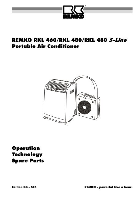
The portable air conditioners <strong>RKL</strong> <strong>460</strong> and <strong>RKL</strong> <strong>480</strong><br />
consist of a portable indoor unit and a weather-resistant<br />
outdoor unit (Fig. 1).<br />
The indoor and outdoor unit are connected to one another<br />
via a flexible connecting line. The outdoor unit can<br />
be hooked onto the back of the indoor unit for transport<br />
or storage (Fig. 2).<br />
Control panel Air outlet grill Connecting line<br />
Indoor unit<br />
/ 1<br />
Outdoor unit<br />
The unit’s primary function is to air-condition rooms.<br />
Fig. 1<br />
It also filters and dehumidifies the air, thus creating a<br />
comfortable climate in the room. The unit can also be<br />
used to circulate air with no cooling effect. It also has a<br />
dehumidifying mode.<br />
The unit operates fully-automatically and offers a range<br />
of other options thanks to its microprocessor control.<br />
The unit is comfortably operated via the control panel<br />
on the indoor unit or via the infrared remote control that<br />
comes with it.<br />
The unit is particularly suited for flexible use. The detachable<br />
connecting line lets it be installed as a stationary<br />
unit.<br />
Connecting line<br />
Cover<br />
Air intake grill<br />
Power cable<br />
Dust filter<br />
Suspension (outdoor unit)<br />
Water outflow<br />
Handle<br />
Prior to putting the unit into operation, ensure that all<br />
safety instructions have been observed.<br />
Please note that the unit operates most efficiently and<br />
most comfortably when put into operation before the<br />
hottest part of the day, e.g. the morning.<br />
The selected target temperature should be 4 to 7 °C below<br />
the outside temperature. It should never be lower<br />
because the room temperature would feel too cold<br />
when coming from a non-air-conditioned room.<br />
The selected target temperature does not affect the<br />
performance of the unit! This means that when temperatures<br />
in the room are high, it is not practical to adjust<br />
the unit to the lowest possible target temperature.<br />
The outdoor unit <strong>RKL</strong> <strong>460</strong>/<strong>480</strong> AT is only guaranteed<br />
to operate at room temperatures of 20 - 35 °C .<br />
5<br />
Fig. 2<br />
Indoor unit
&<br />
The unit may only be put into operation once it has been<br />
installed following all instructions contained in the “Safety<br />
Hints” and “Installation Instructions” sections.<br />
1 "On / Off" button<br />
2 "MODE" button (operating mode and fan setting)<br />
3 "COMP. ON" display (compressor is running)<br />
6<br />
There are 5 options available. Display 10 shows the<br />
selected operating mode.<br />
The sequence is: AUTO HI MED LO FAN<br />
AUTO Cooling mode, automatic fan rotation independent<br />
of room temperature.<br />
HI Cooling mode, highest fan setting.<br />
MED Cooling mode, medium fan setting.<br />
LO Cooling mode, lowest fan setting.<br />
FAN Ventilate only, no cooling.<br />
THERMO CONTROL<br />
COMP. ON<br />
When the compressor is started again for a second<br />
time, a minimum of three minutes must elapse beforehand<br />
for safety reasons. During this time, the<br />
"COMP ON" display blinks.<br />
4 "THERMO CONTROL" button (temperature selection)<br />
After the unit has been connected to the power supply<br />
and manually switched on, the target temperature is<br />
automatically set to 25°C. This can be changed using<br />
the arrow buttons in 1°C increments between 20 and<br />
30°C:<br />
Left arrow button = Higher target temperature<br />
Right arrow button = Lower target temperature<br />
This is shown in display 7.<br />
FAN LO MED HI AUTO<br />
5 "TIMER" button (timer clock)<br />
MODE I / O<br />
7 4 3 10 2 1<br />
REMOTE<br />
DRAIN WATER<br />
AUTO<br />
SWING<br />
TIMING<br />
TIMER<br />
Fig. 3<br />
The timer can be preset for a maximum of 24 hours.<br />
The amount of time is shown on display 7. The timer<br />
has two functions:<br />
ON<br />
OFF<br />
SET RESET<br />
8 11 6 9 5 7<br />
Fig. 4<br />
1. Unit switches on automatically<br />
When the unit is off, using the "SET" button, the user<br />
can enter the number of hours after which the unit is<br />
to be switched on. Each time the button is pressed,<br />
the number of hours is increased by 1. If this function<br />
is activated, "TIMING ON" 9 is lit up<br />
After the timer has been activated, the operating<br />
mode and target temperature can be set as described<br />
above.<br />
2. Unit switches off automatically<br />
When the device is on, using the "SET" button, the<br />
user can enter the number of hours after which the<br />
device is to be switched off. Each time the button is<br />
pressed, the number of hours is increased by 1. If<br />
this function is activated, "TIMING OFF" 9 is lit up.<br />
To disable the timer or change the setting, press<br />
the "RESET" button.<br />
Information about the timer:<br />
If the "On / Off" button is pressed when the timer is<br />
set to switch the device off, this setting is cleared<br />
and the unit switches off.<br />
If the "SET" button is pressed while the timer is activated,<br />
the remaining time is shown on the display.<br />
Each time the "SET" button is pressed, the remaining<br />
time is increased by one hour.<br />
6 "AUTO SWING" button<br />
Pressing this button activates the automatic motion<br />
of the horizontal plate fins on the air outlet grill.<br />
Pressing this button again stops this motion.<br />
The "AUTO SWING" function can be deactivated by<br />
repeatedly pressing this button in quick sequence to<br />
adjust the direction of the horizontal air outlet.<br />
Never adjust the horizontal plate fins manually!<br />
7 Display<br />
Normally, the target temperature is displayed here. If<br />
the thermo control button or the TIMER button is<br />
pressed, the display switches for 5 seconds to the<br />
corresponding setting.<br />
8 REMOTE-SENSOR (sensor remote control)<br />
The unit receives the signals sent from the infrared<br />
remote control via the "REMOTE SENSOR".<br />
Special accessory for <strong>RKL</strong> <strong>460</strong>.<br />
9 "TIMING ON" display<br />
If this display is lit up, the unit will automatically be<br />
switched on after a preset amount of time.<br />
9 "TIMING OFF" display<br />
If this display is lit up, the unit will automatically be<br />
switched off after a preset amount of time.
10 Operating mode and fan setting display<br />
This display provides information about the operating<br />
mode and the fan setting which have been selected.<br />
11 "DRAIN WATER" display (Water tank full)<br />
When the water tank is full, the "DRAIN WATER" and<br />
"MODE" displays blink and an alarm goes off. The<br />
compressor automatically switches off. After the water<br />
tank has been emptied and replaced, the unit<br />
switches back to automatic operation.<br />
Information about the water tank:<br />
During normal operation, the water tank will not fill up<br />
because the condensation is pumped out of the tank via<br />
the connecting line to the outdoor unit.<br />
Make sure that the lower edge of the outdoor unit<br />
is 1.8 meters above the lower edge of the indoor<br />
unit.<br />
The water tank must be emptied when fixing malfunctions.<br />
Proceed as follows:<br />
1. Remove the water tank drainage tube on the back of<br />
the indoor unit from its holder.<br />
2. Remove the sealing cap from the tube.<br />
3. Collect the water that drains out.<br />
4. Then reinsert the sealing cap into the tube.<br />
5. Replace the tube into its holder.<br />
. ' 2 &<br />
All settings can also be made using an infrared remote<br />
control.<br />
2<br />
5<br />
6<br />
MODE<br />
set<br />
TIMER<br />
reset<br />
AUTO<br />
SWING<br />
POWER<br />
on / off<br />
THERMO<br />
CONTROL<br />
1<br />
4<br />
Fig. 5<br />
A description of the button functions (see picture below)<br />
can be found in the “Control panel” section. The remote<br />
control’s range is approximately 5 m.<br />
Power is provided by two 1.5 V AAA batteries. (supplied<br />
with the remote control)<br />
Cooling<br />
'<br />
1. Switch the unit on with the "On / Off” button.<br />
2. Set the target temperature using the arrow buttons.<br />
3. Select the fan setting (AUTO, HI, MED or LO) with<br />
the "MODE" button.<br />
Ventilation (circulation)<br />
1. Switch the unit on with the "On / Off” button.<br />
2. Set the FAN operating mode with the "MODE” button.<br />
3. Please note: in circulation mode, the outdoor unit<br />
can remain in the room. But do not attach the outdoor<br />
unit to the indoor unit.<br />
Dehumidifying<br />
Set up the indoor unit and the outdoor unit in the room<br />
to be dehumidified.<br />
1. Make sure that the indoor unit is not drawing in<br />
warm air from the outdoor unit.<br />
2. Do not attach the outdoor unit to the indoor unit.<br />
3. Please note: the condensation which forms during<br />
dehumidifying may not be pumped to the outdoor<br />
unit because otherwise it would be expelled to the<br />
air in the room or would drip out of the outdoor unit.<br />
4. Remove the water tank drainage tube from the back<br />
of the indoor unit from its holder and remove the<br />
sealing cap.<br />
5. Guide the condensation at an incline to a drain or a<br />
container.<br />
Make sure that the external container does not<br />
overflow!<br />
This may cause water damage.<br />
6. Switch the unit on with the On / Off button.<br />
7. Set the unit to the lowest target temperature with the<br />
temperature selector button.<br />
8. Using the MODE button, set the lowest fan speed.<br />
LO.<br />
7
. .<br />
The standard unit is equipped with a connecting line between<br />
the indoor unit and the outdoor unit which makes<br />
it ready for operation.<br />
It comes with various accessories for assembling the outdoor<br />
unit.<br />
There are different ways to set up the indoor unit and<br />
outdoor unit which are described in the following section.<br />
Indoor unit<br />
The inner unit is installed in the desired location with<br />
the air outlet side facing the room. When installing the<br />
unit, make sure to comply with the safety instructions.<br />
Connecting line<br />
The connecting line can be guided to the outside<br />
through a partially opened window or door. The connecting<br />
line can be detached from the indoor unit which<br />
means that it can also be guided through a wall leadthrough<br />
(Ø min. 60 mm).<br />
When laying the connecting line, follow these instructions:<br />
8<br />
There must be a minimum of 20 cm between the<br />
back of the unit (air intake) and the wall.<br />
The connecting line may never be pinched or bent.<br />
The connecting line may not be pulled or subject to<br />
any other mechanical force.<br />
To prevent the formation of condensation, the hose<br />
insulation and the protective cover may not be damaged.<br />
Outdoor unit<br />
The outdoor unit expels the heat transported out of the<br />
room to the outside air. To perform this function, the<br />
outdoor unit can either be placed on the floor or hung<br />
on an outside wall.<br />
Floor installation<br />
To set up the outdoor unit on a terrace or balcony, it is not<br />
necessary to use fasteners.<br />
The outdoor unit must be placed horizontally and protected<br />
from direct sunlight. A minimum distance of 20<br />
cm must be maintained between the air intake side and<br />
the wall.<br />
Air must be able to flow freely out of the unit (min. 50<br />
cm distance to other objects). The connecting line is<br />
guided through an opening in a door or window (Fig. 6<br />
and 7).<br />
Make sure to maintain the minimum distances. The<br />
air coming out of the indoor unit and the outdoor<br />
unit may not be blocked.<br />
20 cm<br />
20 cm<br />
Fig. 6<br />
Fig. 7<br />
Mounting on the outside wall with wall holder<br />
1. Attach the supplied wall holders to the wall.<br />
2. Hang the to outdoor unit in the wall holders and secure<br />
it with the screws supplied M4 (Fig. 8 and 9).<br />
The wall holders can be attached with the fasteners<br />
supplied (dowel 6 mm and screws). If these are not suitable<br />
for the material the wall is made of, fastening units<br />
with adequate retention force are to be placed.<br />
Fig. 8<br />
Fig. 6a<br />
When mounting the holder, make sure that the line is<br />
not placed under any strain and that the insulation is<br />
not damaged.
Safety screw M4<br />
Mounting on an outside wall with straps<br />
Another way to attach the outdoor unit to a wall or to a<br />
parapet in the outer area is to use straps.<br />
1. Hook the wall holders onto the outdoor unit and secure<br />
them with the M4 safety screws.<br />
Here, the wall holders maintain the proper distance<br />
to the wall.<br />
2. Hook one end of the strap into the fastening loops<br />
on the outer part with the snap hook.<br />
3. Hang the other end of the strap into the loop screws<br />
attached to the wall or parapet (Fig. 10).<br />
Make sure the fasteners are securely attached.<br />
Snap hook Fastening loop<br />
Safety screw M4<br />
Mounting height<br />
353 mm<br />
Loop screw<br />
220 mm<br />
Fig. 9<br />
Fig. 10<br />
The outdoor units (lower edge) may only be mounted a<br />
maximum of 1.8 m above the setup height of the indoor<br />
unit (Fig. 11).<br />
The condensation pump is only guaranteed to pump<br />
condensation that builds up in the indoor unit to the outdoor<br />
unit up to this height.<br />
If the outdoor unit is mounted below the setup height of<br />
the indoor unit, a distance of 1.5 m may not be exceeded.<br />
/ 0<br />
To shut down the unit, always switch it off with the On /<br />
Off button on the control panel. Only now can you unplug<br />
it on the power supply.<br />
Never shut the running unit off by pulling the power plug.<br />
Storage<br />
20 cm<br />
If the unit is to be taken out of operation for a longer period<br />
of time, for example, over the winter, proceed as<br />
follows:<br />
1. Empty the internal water tank via the water drainage<br />
tube on the back of the indoor unit.<br />
2. To do this, remove the tube from its holder and remove<br />
the sealing cap.<br />
3. Collect the water that drains out.<br />
4. Reinsert the sealing cap and place the tube securely<br />
in its holder.<br />
5. Let the unit run for approximately 3 hours in circulation<br />
mode.<br />
This removes any remaining moisture from the unit.<br />
6. Switch the unit off with the On / Off switch.<br />
7. Unplug the power cable and wind it up.<br />
It can be attached to the back of the indoor unit.<br />
max. 1,8 m<br />
9<br />
Fig. 11<br />
Depending on the weather, water may drain out of<br />
the water outlet on the back of the outdoor unit.<br />
This is a normal occurrence.<br />
Select the location for mounting the outdoor unit<br />
in such a way that the outcoming water does not<br />
cause any damage.
8. Clean the dust filter and the plastic surfaces.<br />
9. Hang the outdoor unit onto the indoor unit.<br />
10. Protect the unit from dust with a plastic tarp.<br />
11. Store the unit in a cool, dry place that is protected<br />
from sunlight.<br />
0<br />
&<br />
The connection line is connecting to the indoor unit by<br />
quick-release fasteners. These make it possible to detach<br />
the connecting line from the indoor unit for assembly<br />
purposes without any coolant draining out.<br />
5. Unscrew the fastening clamp of the connecting line.<br />
See Fig. 13.<br />
6. Press on the lug on the side of the connector and<br />
remove the connector from the socket.<br />
7. Remove the upper part of the holder by unscrewing<br />
the two screws.<br />
8. Pull the water tube out.<br />
10<br />
To safely detach the connecting line, make sure to<br />
observe the following instructions.<br />
During the entire process, the unit must be unplugged<br />
from the power source! It may only be put back into operation<br />
wants all connections have been re-established<br />
and tested. The fasteners and all covers must be reattached<br />
prior to operation.<br />
You must proceed as follows:<br />
1. Switch the unit off.<br />
2. Unplug the unit from the power supply.<br />
3. Remove the 2 screws on the cover on the back of<br />
the unit (Fig. 12).<br />
4. Remove the cover from the unit.<br />
Cover<br />
Screws<br />
Fig. 12<br />
It is possible that any remaining water will come<br />
out of the water tube.<br />
Connecting line<br />
Fastening clamp<br />
Connector<br />
Water tube<br />
Holder<br />
9. Unscrew the left cap nut with the wrench supplied<br />
SW 24.<br />
Make sure to apply counter-pressure on the lower<br />
coupling with the second wrench SW 21 (Fig 14).<br />
Never turn the inflexible lower part!<br />
Fig. 13<br />
10. Keep turning until the connection is detached.<br />
Should refrigerant leak out with a slight hissing<br />
noise, keep turning the screws.<br />
Apply counterpressure<br />
tighten<br />
loosen<br />
11. Unscrew the right cap nut with the wrench supplied<br />
SW 24.<br />
Make sure to apply counter-pressure on the upper<br />
coupling with the second wrench SW 21 (Fig. 15).<br />
Never turn the inflexible upper part!<br />
Fig. 14<br />
12. Keep turning until the connection is detached.<br />
Should refrigerant leak out with a slight hissing<br />
noise, keep turning the screw.<br />
Apply counterpressure<br />
loosen<br />
tighten<br />
Fig. 15
13. Screw the supplied protective caps onto the 4 coupling<br />
halves (Fig. 16).<br />
Protective<br />
caps<br />
Protective<br />
caps<br />
14. Provide for a wall lead-through Ø 60 mm .<br />
15. After setup or assembly of the indoor unit and outdoor<br />
unit, the connecting line is attached to the indoor<br />
unit in the reverse order (Points 12 to 1).<br />
16. After attaching the connection, make sure that the<br />
couplings are tightly sealed.<br />
Comments about detaching the connection line:<br />
The units may only be detached right before mounting<br />
and they should only remain disconnected as<br />
long as absolutely necessary.<br />
Before the lines are reconnected, make sure that no<br />
dirt, moisture or other foreign matter has adversely<br />
affected proper functioning of the couplings.<br />
Reattach the fastening clamp after the lines have<br />
been connected.<br />
The lines should only be detached and reconnected<br />
by authorised personnel.<br />
The unit can be detached and reconnected approximately<br />
10 times when done properly without any<br />
noticeable decline in cooling performance.<br />
' 3<br />
Fig. 16<br />
Regular care and the observation of a number of basic<br />
rules will ensure the dehumidifier’s long service life and<br />
reliable operation.<br />
The unit should be inspected and cleaned thoroughly<br />
after each long period of operation, at a minimum once<br />
a year.<br />
All moving parts have been permanently lubricated.<br />
The complete cooling system is a closed-loop system<br />
that requires little maintenance. It may only be serviced<br />
by authorised repair centres.<br />
The unit may only be cleaned with a clean, soft and<br />
slightly damp cloth which is used to carefully wipe the<br />
dirt from the surface.<br />
Only use warm water.<br />
Maximal 40 °C warm.<br />
Thoroughly clean the air output and intake openings<br />
on a regular basis.<br />
In our experience, this is the first place where dirt<br />
accumulates.<br />
Never forget to clean the water tank on a regular basis.<br />
Do not use aggressive cleansers or cleaning products<br />
containing solvents.<br />
Never clean the unit under a stream of water.<br />
& 0 1<br />
The indoor unit is equipped with an dust filter. It can be<br />
pulled out of the back of the unit. The dust filter must be<br />
cleaned at regular intervals.<br />
To clean the dust filter, proceed as follows:<br />
1. Remove the dust filter. (Fig. 17).<br />
2. Clean the dust from the filter.<br />
If the filter is only slightly dirty, you can use a vacuum<br />
cleaner.<br />
3. If the dust filter is very dirty, clean it carefully in<br />
warm water.<br />
4. Then let the filter air dry.<br />
Dust filter<br />
Fig. 17<br />
5. Reinsert the filter into the unit<br />
In case of extreme dirt the dust filter is to be replace.<br />
Never use the unit without installed dust filter!<br />
Without a dust filter the plate fins of the evaporators<br />
would become dirty and the capacity of the<br />
unit would be decreased.<br />
11
Repairs of the cooling and electrical systems may only be performed by an authorised service centre! Always remove<br />
the power plug from the plug socket when working on the unit!<br />
This unit has been designed based on state of the art manufacturing methods and it has been tested repeatedly to<br />
ensure that it is working properly. However, should problems occur, refer to the following list.<br />
Should the unit still not work after performing these functional checks, please contact an authorised service centre.<br />
Problem Possible cause Remedy<br />
The unit does not start<br />
The unit is either not cooling<br />
at all or only cooling a little<br />
bit.<br />
Condensation water leaks<br />
out of the unit.<br />
12<br />
0<br />
Power failure.<br />
Check voltage and wait for the unit to start<br />
again.<br />
Defective power fuse / main switch is off Replace power fuse. Switch on main switch.<br />
Power supply line damaged. Maintenance by authorised personnel.<br />
Water tank is full.<br />
“DRAIN WATER” LED lit up.<br />
Empty container above the water drainage<br />
tube.<br />
Unit is switched on with the timer function. Press the On / Off button again.<br />
Dirty dust filter, input and/or output opening<br />
blocked by foreign matter.<br />
Temperature setting too high. Lower temperature.<br />
Windows and doors open.<br />
Thermal load increased.<br />
The unit is not standing upright.<br />
Clean the filter. Make sure that the input<br />
and/or output opening are not blocked.<br />
Close windows and doors.<br />
Reduce thermal load.<br />
Place upright and make sure it is firmly in<br />
place.<br />
Sealing cap is not in place. Reseal the water drainage tube tightly.<br />
Model <strong>RKL</strong> <strong>460</strong> new <strong>RKL</strong> <strong>480</strong> <strong>RKL</strong> <strong>480</strong> S-Line<br />
Nominal Cooling capacity 1) kW 4,18 4,84<br />
Energy efficiency class 1) B B<br />
Energy efficiency ratio EER 1) 3,05 3,01<br />
Working range (indoor unit) °C +21 to +35 +16 to +35<br />
Working range (outdoor unit) °C +15 to +45<br />
Refrigerant R 407C<br />
Air performance max. indoor unit m³/h 450 / 520 / 600 <strong>480</strong> / 550 / 630<br />
Air performance max. outdoor unit m³/h 640 680<br />
Sound pressure level indoor unit 2) dB(A) 48 / 50 / 52<br />
Sound pressure level outdoor unit 2) dB(A) 51<br />
Electrical connection V / Hz 230 / 1~/ 50<br />
Protection class indoor / outdoor unit IP 24 / X4<br />
Nominal power consumption kW 1,37 1,61<br />
Nominal current 1) A 6,05 7,56<br />
Refrigerant charge kg 0,89 1,03<br />
Connecting line, usable length m 2.300, not extended<br />
Dimensions indoor unit width mm 695<br />
height mm 470<br />
depth mm 335<br />
Dimensions outdoor unit width mm 490<br />
height mm 510<br />
depth mm 230<br />
Weight indoor unit kg 35,0 35,5<br />
Weight outdoor unit kg 13,0 13,0<br />
Color white white silver<br />
Serial number 506... 507... 508...<br />
Ref. No. 1613<strong>460</strong> 1613<strong>480</strong> 1613481<br />
1) Room temperature of DB 27 °C / WB 19 °C, outdoor temperature of DB 35 °C / WB 24 °C<br />
2) Distance 1m
4 0 2<br />
PCB1 = Control panel<br />
PCB2 = Control board<br />
SM = Swing motor<br />
FM1 = Fan motor (indoor unit)<br />
FM2 = Fan motor (outdoor unit)<br />
WM = Water pump<br />
CM = Compressor motor<br />
OLP = Overload protection (compressor)<br />
CX1 = Capacitor fan motor (indoor unit)<br />
CX2 = Capacitor fan motor (outdoor unit)<br />
CX3 = Capacitor (compressor motor)<br />
TH = Thermostat sensor<br />
MS1 = Micro switch (water tank full)<br />
MS2 = Micro switch (water pump on/off)<br />
Y = yellow<br />
W = white<br />
R = red<br />
BU = blue<br />
BR = brown<br />
BK = black<br />
GR = grey<br />
OR = orange<br />
Only <strong>RKL</strong> <strong>480</strong><br />
We reserve the right to make modifications in dimensions and construction in the interests of technical progress.<br />
13
14<br />
5 ' ' 6<br />
Indoor unit<br />
39<br />
1<br />
3<br />
Outdoor unit<br />
5<br />
4<br />
24<br />
60<br />
38<br />
13<br />
57<br />
2<br />
23 22<br />
15<br />
14<br />
6<br />
20<br />
21<br />
11<br />
40<br />
16<br />
55<br />
18<br />
56<br />
50<br />
12<br />
17<br />
19<br />
53<br />
37<br />
25<br />
26<br />
52<br />
We reserve the right to make modifications in dimensions and construction in the interests of technical progress.<br />
41<br />
27<br />
28<br />
31<br />
10<br />
54<br />
58<br />
33<br />
32<br />
13<br />
35<br />
30<br />
42<br />
29<br />
59<br />
36<br />
35<br />
34<br />
61<br />
7<br />
51<br />
8<br />
9
Indoor unit<br />
No. Designation Ref. No.<br />
1 Cover, front<br />
3 ' (<br />
!" # $"<br />
1106060<br />
Cover, front <strong>RKL</strong> <strong>480</strong> S-Line 1106120<br />
2 Handle 1106061<br />
Handle <strong>RKL</strong> <strong>480</strong> S-Line 1106021<br />
3 Cover, top 1106062<br />
4 Air outlet grill 1106063<br />
5 Plate fins 1106064<br />
6 Adjusting lever (plate fins) 1106065<br />
7 Cover, rear 1106066<br />
Cover, rear <strong>RKL</strong> <strong>480</strong> S-Line 1106122<br />
8 Dust filter 1106067<br />
Dust filter <strong>RKL</strong> <strong>480</strong> S-Line 1106123<br />
9 Cover, connecting line 1106068<br />
Cover, connecting line <strong>RKL</strong> <strong>480</strong> S-Line 1106124<br />
10 Cover, bottom 1106069<br />
11 Base plate, cpl. 1106070<br />
12 Transport wheels 1106071<br />
13 Cover, side (left / right) 1106072<br />
14 Water tank 1106073<br />
15 Separating plate 1106074<br />
16 Fan housing 1106075<br />
17 Holder (micro switch) 1106076<br />
18 Micro switch (water tank full) 1106077<br />
19 Micro switch (water pump on/off) 1106078<br />
20 Floater (water tank full) 1106079<br />
21 Floater (water pump on/off) 1106080<br />
22 Swing motor (plate fins) 1106032<br />
23 Clutch (swing motor) 1106081<br />
24 Water pump, cpl. 1106082<br />
25 terminal strip 1106083<br />
26 Capacitor, 1,5 µF (fan indoor unit) 1106002<br />
27 Capacitor, 3,0 µF (fan outdoor unit) 1106003<br />
28 Capacitor (compressor motor) 1106117<br />
29 Frame 1106085<br />
30 Fan, cpl. <strong>RKL</strong> <strong>460</strong>-<strong>480</strong> 1106099<br />
31 Motor (fan) 1106087<br />
32 Compressor, cpl. <strong>RKL</strong> <strong>460</strong> 1106115<br />
The units are repeatedly tested at the production site to<br />
ensure that they are working properly. If a malfunction<br />
occurs that cannot be eliminated by the operating personnel,<br />
please contact your dealer or contact person.<br />
For the guarantee to be valid, the purchaser or his customer<br />
must completely fill out the “guarantee certificate”<br />
enclosed with all units and send it back to REMKO<br />
GmbH & Co. KG.<br />
Operation/handling which does not comply with<br />
these instructions is prohibited!<br />
In cases of non-compliance, we assume no liability<br />
and the guarantee becomes null and void.<br />
Outdoor unit<br />
No. Designation Ref. No.<br />
Compressor, cpl. <strong>RKL</strong> <strong>480</strong> 1106116<br />
33 Evaporator 1106090<br />
34 Coupling , Set (1x m / 1x w) 1106091<br />
35 Connecting line, cpl. 1106092<br />
36 Holder, cpl. 1106093<br />
37 Water tube 1106094<br />
38 Control panel 1106095<br />
39 Labelling (control panel) 1106096<br />
40 Control board <strong>RKL</strong> <strong>460</strong> 1106097<br />
Control board <strong>RKL</strong> <strong>480</strong> 1106130<br />
41 Sensor (temperature) 1106098<br />
42 Power cable with plug 1106043<br />
50 Cover, rear 1106100<br />
Cover, rear <strong>RKL</strong> <strong>480</strong> S-Line 1106125<br />
51 Cover, front 1106101<br />
Cover, front <strong>RKL</strong> <strong>480</strong> S-Line 1106125<br />
52 Cover, bottom 1106102<br />
53 Fan housing 1106103<br />
54 Fan <strong>RKL</strong> <strong>460</strong>-<strong>480</strong> 1106105<br />
55 Mount (motor) 1106106<br />
56 Angle support 1106107<br />
57 Motor (fan) 1106108<br />
58 Condenser 1106109<br />
59 Seal 1106110<br />
60 Wall holder 1106111<br />
61 Infrared-remote control 1613135<br />
not shown<br />
Set of fasteners parts cpl. (outdoor unit) 1106112<br />
Sensor, antifreeze <strong>RKL</strong> <strong>480</strong> 1106131<br />
3 2 '<br />
Important information about recycling!<br />
Only authorised personnel they come into contact with<br />
the cold cycle. This ensures that refrigerant does not<br />
escape into the environment when the unit is being repaired.<br />
Both the refrigerant and the system parts are subject to<br />
special requirements for disposal.<br />
The refrigerant in use is a safety refrigerant. This<br />
means that, should damage occur, the quantities released<br />
will not cause injury to the respiratory systems<br />
of people and animals. Do not touch the liquid<br />
refrigerant as it can freeze the skin!<br />
15
REMKO GmbH & Co. KG<br />
Air-Conditioning and Heating Technology<br />
D-32791 Lage • Im Seelenkamp 12<br />
D-32777 Lage • P.O. Box 1827<br />
Phone: +49 52 32 606 - 0<br />
Fax: +49 52 32 606- 260<br />
E-mail: export@remko.de<br />
Internet: www.remko.de