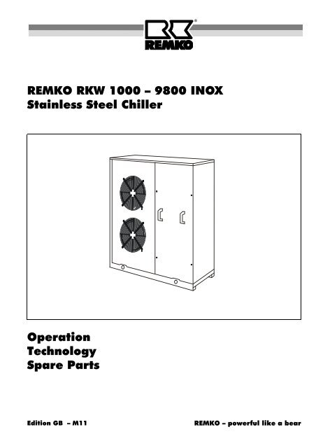
REMKO RKW 1000 â 9800 INOX Stainless Steel Chiller Operation ...
REMKO RKW 1000 â 9800 INOX Stainless Steel Chiller Operation ...
REMKO RKW 1000 â 9800 INOX Stainless Steel Chiller Operation ...

Create successful ePaper yourself
Turn your PDF publications into a flip-book with our unique Google optimized e-Paper software.
<strong>REMKO</strong> <strong>RKW</strong> <strong>1000</strong> – <strong>9800</strong> <strong>INOX</strong><br />
<strong>Stainless</strong> <strong>Steel</strong> <strong>Chiller</strong><br />
<strong>Operation</strong><br />
Technology<br />
Spare Parts<br />
Edition GB – M11<br />
<strong>REMKO</strong> – powerful like a bear
Operating Instructions<br />
Read these instructions carefully before setting up/operating the unit!<br />
Our guarantee becomes null and void if the unit is used, set up<br />
<strong>REMKO</strong> <strong>Stainless</strong> <strong>Steel</strong> <strong>Chiller</strong><br />
<strong>RKW</strong> <strong>1000</strong> <strong>INOX</strong> / 1600 <strong>INOX</strong> / 2600 <strong>INOX</strong><br />
3600 <strong>INOX</strong> / <strong>RKW</strong> 4500 <strong>INOX</strong> / 8000 <strong>INOX</strong> / <strong>9800</strong> <strong>INOX</strong><br />
Contents Page<br />
Unit Description 4<br />
Safety Hints 4<br />
Transport and Packaging 5<br />
<strong>Operation</strong> 5<br />
Maintenance and Service 9<br />
Shutting Down the Unit 10<br />
Alarm Description 10<br />
Troubleshooting 11<br />
Technical Data 12<br />
Dimensions 13<br />
or maintained improperly,<br />
or if modifications are made to the supplied unit without our prior consent.<br />
Subject to alterations!<br />
Contents Page<br />
Assembly Instructions for Service Personnel 14<br />
Unit Assembly 14<br />
Storage Modules for <strong>RKW</strong> 3600 to <strong>9800</strong> I 17<br />
Cable Remote Control 20<br />
Electrical Connection 21<br />
Hydraulic System 24<br />
Initial <strong>Operation</strong> 25<br />
Environment and Recycling 26<br />
Service and Guarantee 26<br />
� Always keep these operating instructions near or on the unit! �<br />
3
Unit Description<br />
<strong>REMKO</strong> chilled water air-conditioning systems consist<br />
of an outer part ready which is ready to be connected,<br />
the air-cooled chiller (<strong>REMKO</strong> <strong>RKW</strong> <strong>INOX</strong>) and one or<br />
more inner units (cold water consumers: <strong>REMKO</strong> KLT,<br />
WLT, DKT and FLG). All components required for cooling<br />
are located in the outer part.<br />
A hermetically closed cooling cycle in the chiller cools<br />
the water (or a brine made of water and antifreeze) to<br />
up to 5 °C via a plate heat exchanger.<br />
A circulation pump integrated either into the unit or in<br />
the storage module transports the cold water to the inner<br />
unit(s). To expand the water volume and extend the<br />
operating time, there is also a cold water tank with<br />
safety assembly either in the unit or located in the separate<br />
storage module.<br />
In the inner units, the air in the room is guided through<br />
the heat exchanger of the inner units by means of a<br />
quiet fan. When the air in the room leaves the unit, it is<br />
cooled, demoisturized and filtered. The water warms up<br />
and transports the heat absorbed from the room back to<br />
the outer part where it is passed along to the cooling cycle<br />
and the surroundings.<br />
The <strong>RKW</strong> <strong>1000</strong>, 1600 and 2600 <strong>INOX</strong> chillers all have a<br />
hydraulic system that is ready to be connected with a:<br />
◊ Buffer tank<br />
◊ Expansion vessel<br />
◊ Safety valve<br />
◊ Flow switch (differential pressure monitor)<br />
◊ Manometer<br />
◊ Ventilation<br />
◊ Ventilation valve<br />
◊ Drain valve<br />
The <strong>RKW</strong> 3600 <strong>INOX</strong> chiller models and higher can be<br />
easily equipped with a storage module that has an integrated<br />
hydraulic system, even at a later time.<br />
The system is regulated by means of a self-sufficient<br />
microprocessor that monitors system safety parameters<br />
and displays any malfunctions and monitors the set cold<br />
water temperature. A connection between the chiller<br />
and the cold water consumers is not required.<br />
To air condition rooms, an outer part is usually used in<br />
connection with the appropriate inner units (consumers).<br />
Here, there are various options available depending on<br />
how the unit is being used. In addition to standalone<br />
units, wall and ceiling chests, ceiling cassettes with various<br />
capacities can also be selected for mounting on intermediate<br />
walls.<br />
<strong>REMKO</strong> chillers are suitable for almost every type of application<br />
when used with the right consumers if the priority<br />
is cooling according to needs.<br />
Thanks to modern technology, the chillers require up to<br />
80 % less coolant than other cooling and airconditioning<br />
systems.<br />
4<br />
The coolant is only necessary to cool the transport medium<br />
(water or brine). In conventional systems, the coolant<br />
is also required to transport the heat from the inner<br />
units (consumers) to the outer part.<br />
This makes another advantage of the <strong>REMKO</strong> chillers<br />
evident; they do not require coolant lines to the inner<br />
units (cold water consumers). All connection lines are<br />
designed to be water lines with the correct dimensions<br />
and heat insulation.<br />
Ideally, lines of an existing heating network can be integrated<br />
into the overall system.<br />
Proper use<br />
The outdoor parts have been designed and fitted exclusively<br />
for operation with <strong>REMKO</strong> indoor units belonging<br />
to the RKV series.<br />
The manufacturer assumes no liability for damage resulting<br />
from non-compliance with manufacturer specifications<br />
and legal requirements, or if modifications are<br />
made to the units.<br />
Safety Hints<br />
Extensive tests have been conducted on the material,<br />
functionality and quality of these units before they were<br />
shipped. These units may only be used in accordance<br />
with their intended purpose. Hazards may arise if the<br />
units are used improperly.<br />
Please make sure to follow these safety instructions.<br />
◊ Make sure that personnel trained in the operation of<br />
the chiller check the unit for visible defects on the operating<br />
and safety mechanisms each time before<br />
putting it into operation.<br />
◊ Before any work on the unit is performed, it must be<br />
disconnected from the power supply and secured<br />
against switching on!<br />
◊ The unit may only be filled up and operated with water<br />
or a mixture of water and glycol (brine)!<br />
◊ Ensure that the air intake and outlet openings are always<br />
clear of foreign objects.<br />
◊ Do not insert any objects into the air intake and outlet<br />
openings.<br />
◊ Do not install the unit close to heat sources.<br />
◊ Make sure to maintain the safety zones described<br />
later in this manual!<br />
◊ Do not use flammable gases such as spray paint in<br />
the direct vicinity of the units.<br />
◊ Make sure that the unit is kept at a safe distance<br />
from flammable materials.<br />
◊ Do not operate the unit if the atmosphere is contaminated<br />
by oil, sulfur or salt.<br />
◊ If there is a cable remote control installed, make sure<br />
to protect it against moisture and direct or indirect<br />
sunlight!
◊ Operate the units exclusively within the permissible<br />
operating ranges.<br />
◊ Do not expose the unit to direct streams of water<br />
High-pressure cleaners, etc.<br />
◊ Protect the connection lines from being damaged, for<br />
example, by animals.<br />
◊ The unit may only be connected to a correctly installed<br />
and grounded power supply.<br />
◊ Never open the unit housing.<br />
There may cause an electric shock.<br />
◊ Operate the unit only when assembled and for their<br />
intended purpose. Keep in mind that it is dangerous<br />
to remove covers protective grilles, etc., during operation;<br />
this can lead to uncontrolled operating situations.<br />
◊ Never operate the unit in rooms susceptible to explosions.<br />
The units are also not suitable for operation in<br />
rooms containing large amounts of dust or aggressive<br />
air.<br />
◊ Installation and repair work may only be performed by<br />
authorised personnel.<br />
◊ Cleaning and minor maintenance work made only be<br />
performed by the operator or an authorised person<br />
designated by him in accordance with the instructions<br />
contained in the section "Maintenance and Service".<br />
◊ If the unit is set up outside and is susceptible to being<br />
hit by lightning, the appropriate countermeasures<br />
must be implemented by an authorised company.<br />
Transport and Packaging<br />
The unit is shipped in a stable transport box made of<br />
wood and cardboard. Please examine the unit when it is<br />
delivered<br />
Make note of any damage or missing parts on the shipping<br />
bill and notify the shipping company and your contract<br />
partner.<br />
We do not assume any liability for subsequent complaints.<br />
Instructions:<br />
◊ When shipped, the units are packaged in a box and<br />
mounted on a palette.<br />
◊ The units must remain upright and be transported<br />
with suitable means. They must also be adequately<br />
secured from falling over.<br />
◊ If the units are transported to a setup location that is<br />
higher up, such as platforms or roofs, they must be<br />
transported in an upright position as shown below.<br />
<strong>Operation</strong><br />
The chiller is operated fully-automatically by an internal<br />
regulation or by an external cable remote control installed<br />
by the customer.<br />
Both types of unit operation allow some parameters to<br />
be changed as well as the water return temperature to<br />
be displayed.<br />
Internal and external regulation<br />
Pulling point<br />
Wooden boards to protect<br />
from pressure<br />
CH-DIN regulation Cable remote control<br />
5
Regulation<br />
CH–DIN regulation of all <strong>RKW</strong> <strong>INOX</strong> units<br />
The CH–DIN microprocessor regulates the chiller for all<br />
<strong>INOX</strong> units. It is located in the electrical switch box of<br />
the unit and monitors all control and safety functions:<br />
◊ Controls and displays incoming and outgoing cold<br />
water temperatures<br />
◊ Displays the time delay of the compressor and fan<br />
◊ Checks that the outgoing water temperature is not<br />
too low (frost monitoring)<br />
◊ Displays and controls all safety mechanisms that<br />
have been stopped due to a malfunction<br />
◊ Displays the operating mode<br />
◊ Regulates the condensation temperature<br />
The regulator consists of the basic unit to control unit<br />
operation. A fan board is connected to the basic unit<br />
that controls the rotation of the fan motors by regulating<br />
the output current depending on the liquefaction temperature.<br />
Models <strong>RKW</strong> 3600 <strong>INOX</strong> and higher have two cold cycles.<br />
The second cycle cannot be regulated by the CH–<br />
DIN basic unit because there are not enough inputs and<br />
outputs. For this reason, the extra C2-DIN regulator<br />
controls the second cycle. Programming is, however,<br />
still performed using the CH–DIN basic unit.<br />
CH– DIN panel<br />
6<br />
Value display Arrow keys Code display<br />
CH-DIN<br />
8<br />
Heat<br />
Cool<br />
❅<br />
8. 8<br />
MODE<br />
MENU<br />
Comp<br />
SET<br />
8<br />
STATUS<br />
MENU button STATUS button<br />
MODE button SET button<br />
8<br />
Alarm<br />
Line<br />
ON/OFF<br />
RESET<br />
ON/OFF<br />
RESET button<br />
The panel has two displays: the value display (three<br />
numbers on the left) and the code display (two numbers<br />
on the right).<br />
MENU<br />
STATUS<br />
MODE<br />
The buttons allow operating<br />
processes (parameters) and their associated values to<br />
be changed.<br />
SET<br />
ON/OFF<br />
RESET<br />
Value Display<br />
The value display shows the target value in degrees<br />
with one decimal place in Celsius. It can also display:<br />
◊ All parameter settings<br />
◊ The codes for all alarms<br />
◊ The status of the functions<br />
◊ The operating hours<br />
◊ The shut-off status<br />
8 8. 8<br />
◊ The current delays<br />
A square LED displays minus temperatures and an LED<br />
in the top left-hand corner shows the multiplier of the<br />
displayed value with 100.<br />
Code Display<br />
The code display indicates the number of the parameter<br />
(or the function) whose value or status appears in the<br />
value display. If a parameter is shown in the code display,<br />
the setting appears in the value display.<br />
Arrow Keys<br />
8<br />
8<br />
The set value for each parameter can be changed with<br />
the arrow keys.<br />
When the parameter programming operating mode is<br />
accessed (via the MENU button), both displays show a<br />
value (continuous display). After the SET button has<br />
been pressed, the code display (parameters) starts<br />
blinking. The displayed values can be increased or decreased<br />
using the arrow keys. If the SET is pressed a<br />
second time, the value display blinks. The new values<br />
are saved by pressing the SET button again. Both displays<br />
switch from a blinking display to a continuous display.<br />
MODE Button with two LEDs<br />
The regulation mechanism was designed for use of a<br />
chiller in the cooling operating mode Cool ❅ and as a<br />
heat pump in the cooling and heating operating<br />
modes. Heat<br />
Only the summer operating mode (cooling mode) Cool ❅<br />
may be used for all <strong>INOX</strong> units.<br />
MENU Button with one LED MENU<br />
The MENU button provides access to the parameter list<br />
and displays the parameters on the code display and<br />
the associated value on the value display.<br />
STATUS Button with one LED<br />
MODE<br />
STATUS<br />
The STATUS button provides access to the status list<br />
and displays the status settings by pressing the arrow<br />
keys.<br />
The code display shows the function number of the<br />
function list and the value display shows the corresponding<br />
setting. The codes and their descriptions are<br />
described in the table on page 8.
ON/OFF/RESET Button<br />
ON/OFF<br />
RESET<br />
This button is used to switch the unit on and off. If the<br />
alarm has been set off and the unit has to be manually<br />
reset, this button is pressed to prevent further alarms<br />
from being acknowledged. At the same time, the normal<br />
operating function of the unit is restored.<br />
Alarm LED<br />
Alarm<br />
If this LED is lit up, the unit’s alarm has gone off and operation<br />
has been interrupted.<br />
SET Button<br />
SET<br />
The parameters settings can be changed by pressing<br />
the SET button together with the arrow keys.<br />
Compressor LED<br />
This LED is not lit up when the compressor is not in operation.<br />
If this LED is blinking, the compressor is currently<br />
in start-up time delay and will begin operation after<br />
this time has elapsed. If this LED is continuously lit<br />
up, the compressor is in operation. The time delay is no<br />
longer active.<br />
Line LED<br />
Fan Board<br />
Line<br />
Comp<br />
This LED is continuously lit up when the regulation is<br />
connected to the power supply.<br />
The fan board is connected to the CH–DIN regulation.<br />
The CH-DIN (C2-DIN) regulation registers the current<br />
condensation temperature via the sensor input ST 5 (ST<br />
6) and passes along the corresponding programmed<br />
output current to the CTK 1 (CTK 2) output of the TK 1<br />
(TK 2) fan board.<br />
The fan motor rotation can be controlled by the modulating<br />
output current.<br />
Fan board TK 1 Fan board TK 2<br />
C2–DIN Additional Regulations for Models <strong>RKW</strong> 3600<br />
and higher<br />
For chillers with cooling capacities higher than 26 kW,<br />
the cooling capacity is divided among two cooling cycles.<br />
The second cycle cannot be regulated using the<br />
CH-DIN regulation because there are not enough inputs<br />
and outputs and requires an additional C2-DIN regulation.<br />
The C2-DIN regulation controls the same functions<br />
together with the CH-DIN regulation. These functions<br />
are only displayed by LEDs. An alarm from the second<br />
cycle is displayed on the CH-DIN regulation display as a<br />
code, e.g. “E 01”.<br />
The CH-DIN regulation is still used to program the settings<br />
of the second cycle.<br />
C2– DIN Additional Regulation<br />
Operating display Compressor 2<br />
Malfunction display<br />
High pressure 2<br />
C2-DIN<br />
Compr.<br />
High press.<br />
C2- DIN additional regulation<br />
Operating Display Compressor 2<br />
Compr.<br />
This display lights up when the compressor of the second<br />
cycle is in operation.<br />
Malfunction Display Compressor 2<br />
Err. compr.<br />
This display lights up when there is a malfunction in the<br />
compressor of the second cycle.<br />
Malfunction Display Fan 2<br />
Err. fan<br />
Malfunction display<br />
Fan 2<br />
Err. compr.<br />
Low press.<br />
Err. fan<br />
This display lights up when there is a malfunction in the<br />
fan of the second cycle.<br />
High Pressure MalfunctionCycle 2<br />
High press.<br />
This display lights up when pressures that are too high<br />
have been set in the second cycle.<br />
Low Pressure MalfunctionCycle 2<br />
Malfunction display Compressor 2<br />
Malfunction display<br />
Low pressure<br />
CH- DIN regulation<br />
Low press.<br />
This display lights up when pressures that are too low<br />
have been set in the second cycle.<br />
7
Determining the Operating Mode (Status)<br />
The Status menu is used to determine the current operating mode of the various system components such as operating<br />
hours, outputs currently set, the current actual values of the sensor inputs and any current malfunctions.<br />
Pressing the STATUS button takes you to the Status menu (Status LED is lit up). The left-hand value display now<br />
indicates the current operating mode of the statuses in the right-hand code display using the index described in the<br />
table below. These can be listed by pressing the arrow keys in sequence:<br />
Programming process<br />
8<br />
Status Status Description Index Meaning<br />
01 Compressor 1 01<br />
02<br />
03<br />
04<br />
06<br />
Compressor 1 in cooling mode<br />
Compressor 1 in heating mode (not in use)<br />
Compressor 1 in defrost cycle (not in use)<br />
Compressor 1 in time delay ON<br />
Compressor 1 OFF<br />
02 Run time Compressor 1 # (value in hours) Operating hours of Compressor 1<br />
03 Fan(s) Cycle 1 01<br />
02<br />
04<br />
06<br />
In operation<br />
Off (defrost for heating pump)<br />
Time delay ON<br />
OFF<br />
05 Rotations condenser fan(s) Cycle 1 # (value as a %) Fan rotation as a percentage<br />
21 Compressor 2 - - -<br />
01<br />
02<br />
03<br />
04<br />
06<br />
22 Run time Compressor 2 - - -<br />
# (value in hours)<br />
23 Fan(s) Cycle 2 - - -<br />
01<br />
02<br />
04<br />
06<br />
25 Rotations condenser fan(s) Cycle 2 - - -<br />
%<br />
40<br />
Sensor incoming water temperature<br />
ST 1 (Cycle 1)<br />
41 Remote control ON/OFF - - -<br />
ON<br />
OFF<br />
42<br />
43<br />
44<br />
45<br />
Sensor outgoing water temperature<br />
ST 2 (Cycle 1)<br />
Sensor outgoing water temperature<br />
ST 3 (Cycle 2)<br />
Sensor condenser temperature<br />
ST 5 (Cycle 1)<br />
Sensor condenser temperature<br />
ST 6 (Cycle 2)<br />
- - -<br />
# (value in °C)<br />
ON<br />
OFF<br />
ERR<br />
- - -<br />
# (value in °C)<br />
ON<br />
OFF<br />
ERR<br />
- - -<br />
# (value in °C)<br />
ON<br />
OFF<br />
ERR<br />
- - -<br />
# (value in °C)<br />
ERR<br />
- - -<br />
# (value in °C)<br />
ERR<br />
46 Cold water pump - - -<br />
01<br />
06<br />
47 Run time cold water pump - - -<br />
# (value in hours)<br />
48<br />
1<br />
8<br />
Defrost heating<br />
(not in use)<br />
STATUS 0 4 0 1<br />
- - -<br />
01<br />
06<br />
0 6<br />
Not installed<br />
Compressor 2 in cooling mode<br />
Compressor 2 in heating mode (not in use)<br />
Compressor 2 in defrost cycle (not in use)<br />
Compressor 2 in time delay ON<br />
Compressor 2 OFF<br />
Not installed<br />
Operating hours of Compressor 2<br />
Not installed<br />
Fans in operation<br />
Off (not in use)<br />
Time delay ON<br />
OFF<br />
Not installed<br />
Fan rotation as a percentage<br />
Not installed<br />
Actual value in 0.1°C intervals<br />
Sensor activated<br />
Sensor not activated<br />
Sensor malfunction or failure<br />
Remote control not installed<br />
Remote control active<br />
Remote control locked<br />
Not installed<br />
Actual value Cycle 1<br />
Sensor activated<br />
Sensor not activated<br />
Sensor malfunction or failure<br />
Not installed<br />
Actual value Cycle 2<br />
Sensor activated<br />
Sensor not activated<br />
Sensor malfunction or failure<br />
Not installed<br />
Actual value condenser Cycle 1<br />
Sensor malfunction or failure<br />
Not installed<br />
Actual value condenser Cycle 2<br />
Sensor malfunction or failure<br />
Not installed<br />
Pump in operation<br />
Pump not in operation<br />
Not installed<br />
Operating hours of the pump<br />
Not installed<br />
Heating in operation<br />
Heating not in operation<br />
0<br />
2<br />
STATUS
Changing the Target Values (Parameters)<br />
A parameter is a modifiable value that can be set by the<br />
operator/installer to adjust the chiller to the specific conditions<br />
and guarantee optimum operation.<br />
For example, the return temperature, the frost protection<br />
alarm temperature and the new switch-on differential<br />
can be changed after the target temperature has<br />
been reached.<br />
Access rights for system operators and qualified maintenance<br />
and service personnel is divided into two parameter<br />
levels. The operator can only change basic parameters<br />
on the first level and the service personnel can<br />
change system-specific parameters on the second level<br />
after entering a password.<br />
A technical data sheet which explains the second parameter<br />
level can be requested separately by a qualified<br />
company from <strong>REMKO</strong> GmbH &Co. KG.<br />
Programming process<br />
MENU<br />
1<br />
8<br />
Table of the first parameter level<br />
1<br />
0<br />
MENU<br />
Parameter Function Unit<br />
First Parameter Level for the System Operator<br />
The first parameter level is accessed by pressing the<br />
ON/OFF/RESET button. The current return temperature<br />
is displayed.<br />
After pressing the MENU button, the programmed value<br />
of Parameter 02 (right-hand code display) appears in<br />
the left-hand display. The right-hand parameter display<br />
begins to blink when the SET<br />
button is pressed. This mode displays the options for<br />
changing the parameters to the programmer.<br />
If one of the arrow keys is now pressed, the parameter<br />
jumps to the next higher or lower parameter.<br />
Once the correct value has been reached for the parameter,<br />
the value display begins to blink after the SET<br />
button has been pressed. The displayed value can now<br />
also be changed using the arrow keys. The programming<br />
level can be exited by pressing the SET button a<br />
third time. The settings are saved and the return temperature<br />
is displayed again.<br />
<strong>RKW</strong> <strong>INOX</strong> factory setting<br />
<strong>1000</strong> 1600 2600 3600 4500 8000 <strong>9800</strong><br />
02 Target value regulation, cooling °C 12,0 12.0 12.0 12.0 12.0 12.0 12.0<br />
03 Target value regulation, heating °C 45.0 45.0 45.0 45.0 45.0 45.0 45.0<br />
04 Cooling hysteresis °C 1.0 1.0 1.0 0.8 0.8 0.8 0.8<br />
05 Heating hysteresis °C 1.0 1.0 1.0 0.8 0.8 0.8 0.8<br />
26 Frost protection alarm target value °C 4.0 4.0 4.0 4.0 4.0 4.0 4.0<br />
92 Password entry - Technical data sheet<br />
Maintenance and Service<br />
The unit almost never requires maintenance. Regular<br />
care and the observation of a number of basic rules will<br />
ensure the unit’s long service life and reliable operation.<br />
◊ We recommend concluding a maintenance agreement<br />
with a company who specialises in this type of<br />
work. This will guarantee that the system operates<br />
safely at all times!<br />
◊ Keep the unit free of dirt, plants and other deposits<br />
and only clean the units with a damp cloth.<br />
Do not expose the units to a direct stream water.<br />
◊ Do not use an abrasive cleaning agent or one that<br />
contains solvent; if the units are extremely dirty, only<br />
use suitable cleaning materials.<br />
SET<br />
0<br />
2<br />
1<br />
0<br />
SET 0 2 0 3<br />
◊ Before taking the unit out of operation for a longer<br />
period of time, clean the plate fins of the unit while<br />
the ventilator is in operation and cover the unit with a<br />
plastic sheet to prevent dirt from entering the unit.<br />
◊ For systems with brine, check the ratio of water to<br />
Antifreeze N or Antifreeze L before taking the unit out<br />
of operation in winter to protect the system from<br />
frost.<br />
◊ We recommend having the unit checked at regular<br />
intervals (once or twice a year) to ensure that it is<br />
functioning properly and there are no leaks.<br />
1<br />
1<br />
SET<br />
9
Shutting Down the Unit<br />
Temporary shutdown<br />
If the unit is to be taken out of operation for a longer period<br />
of time, for example, over the winter, proceed as<br />
follows:<br />
1. Use the remote control to shut down all of the inner<br />
units.<br />
2. Switch off the internal regulation in the chiller (or the<br />
remote control).<br />
3. Have the percentage of glycol is checked by an<br />
authorised company.<br />
4. If only water was used in the hydraulic cycle and no<br />
brine (water and antifreeze), this water must be<br />
drained from system components in areas susceptible<br />
to frost during the period of non-operation. When<br />
the unit is put back into operation, the amount of water<br />
that has been drained must be refilled!<br />
5. Check the inner units and the chiller for any visible<br />
damage.<br />
6. Clean the inner units and outer parts as described in<br />
section 5 “Maintenance” and cover the chiller, if possible,<br />
with a plastic sheet to protect it from weather<br />
conditions.<br />
When the unit is put back into operation after a long period<br />
of non-operation, it must first be checked for external<br />
damage before operation.<br />
List of the alarm codes<br />
10<br />
Alarm Description<br />
Code Alarm Type AUTO MANUAL<br />
E00 Remote control defective (open contact)<br />
E01 High pressure alarm Cycle 1<br />
E02 Low pressure alarm Cycle 1<br />
E03 Condenser overheating Cycle 1<br />
E04 Condenser temperature too high<br />
E05 Frost protection Cycle 1 activated<br />
E06 Sensor defective ST 2 outgoing water Cycle 1<br />
E07 Sensor defective ST 5 condenser Cycle 1<br />
E21 High pressure alarm Cycle 1<br />
E22 Lobe pressure alarm Cycle 1<br />
E23 Condenser overheating Cycle 2<br />
E24 Condenser temperature too high<br />
E25 Frost protection Cycle 2 activated<br />
E26 Sensor defective ST 3 outgoing water Cycle 2<br />
E27 Sensor defective ST 6 condenser Cycle 2<br />
E40 Sensor defective ST 1 incoming water<br />
E41 Flow switch (differential pressure monitor) activated<br />
E42 Hardware defective<br />
To protect the unit, the CH-DIN regulation and the C2-<br />
DIN additional regulation use sensors to check the unit’s<br />
safety mechanisms for temperature, pressure, internal<br />
configuration, etc.<br />
The value display of the CH-DIN regulation indicates the<br />
alarm code by displaying the letter E followed by two<br />
numbers. The cause of the alarm can be determined by<br />
finding the code in the table below. The C2-DIN additional<br />
module also displays the alarm with a corresponding<br />
LED.<br />
On the second parameter level, resetting the alarm can<br />
be programmed after the malfunction has been fixed<br />
The alarms are pre-programmed to automatically reset<br />
at the factory.<br />
If the alarms have been reprogrammed to be reset<br />
manually, the alarm must be reset after the problem has<br />
been fixed by switching the CH-DIN and then on again<br />
with the ON/OFF/RESET button (see programming example<br />
below).<br />
Resetting the alarms after the problem has been fixed<br />
The alarms can be reset by following the programming process below. As an example, the compressor switched off<br />
due to a malfunction caused by dirt in the condenser fins.<br />
Programming process<br />
Overheating of the<br />
condenser as a<br />
result of dirt in the<br />
fins<br />
E<br />
Alarm<br />
2 1<br />
Temperature of the<br />
condenser is lowered<br />
and the fins of<br />
the heat exchanger<br />
are cleaned<br />
0<br />
2<br />
Permanent shutdown<br />
For environmental safety reasons, the chiller may only<br />
be disassembled by authorised service centres.<br />
<strong>REMKO</strong> GmbH & Co. KG or your contract partner would<br />
be happy to provide you with the name of a service centre<br />
in your area.<br />
ON/OFF<br />
RESET<br />
Alarm<br />
ON/OFF<br />
RESET<br />
3<br />
The second parameter level can be<br />
programmed to reset the alarms.<br />
Enter the changed resets in the lefthand<br />
column.<br />
All settings made at the factory<br />
have been pre-programmed to<br />
AUTOMATIC.<br />
1
Troubleshooting<br />
This unit has been designed based on state-of-the-art manufacturing methods and it has been tested repeatedly to<br />
ensure that it is working properly. However, should problems occur, refer to the following list.<br />
Problem Alarm Possible cause Check Remedy<br />
The unit<br />
does not<br />
start or it<br />
switches<br />
itself off<br />
automatically.<br />
The unit is<br />
either not<br />
cooling at<br />
all or only<br />
a little bit<br />
Water<br />
leaks out<br />
of the unit<br />
E01/E02<br />
E21/E22<br />
E00/E21<br />
Power failure<br />
Power fuse / power supply defective<br />
Are all other electrical components<br />
working?<br />
Are all other electrical components<br />
working?<br />
Check voltage and wait for the<br />
unit to start again.<br />
Maintenance by authorised<br />
personnel<br />
Waiting period too short Is the COMP LED blinking? Schedule longer waiting periods<br />
Regulation is not working<br />
Incorrect discharge temperature<br />
or parameter setting<br />
High-low pressure alarm<br />
Remote control / Connection<br />
to C2-DIN defective<br />
E03/E23 Compressor overheating<br />
E04/E24<br />
Liquefaction temperature too<br />
high<br />
E05/E25 Frost protection activated<br />
E06/E07/<br />
E26/E27/<br />
E40<br />
E41<br />
Incorrect electrical rotational<br />
direction<br />
Sensors defective ST1 to ST6<br />
Flow switch (differential pressure<br />
monitor) activated<br />
E42 Hardware defective<br />
Compressor contact defective<br />
Heating capacity was increased<br />
Supply temperature too high<br />
Air in the system<br />
Liquefaction temperature too<br />
hot<br />
Is the LINE LED and to the<br />
COOL LED lit up?<br />
Connect current and select the<br />
COOL operating mode<br />
Check setting Change setting<br />
Are the fans rotating?<br />
Is the pressure in the cold cycle OK?<br />
Is the display working?<br />
Is the connection OK?<br />
Is the temperature of the compressor<br />
above approx. 100 °C?<br />
Are the fins clean and have the operating<br />
ranges been maintained?<br />
Is the supply temperature 4°C or<br />
lower?<br />
It is the alarm activated when the<br />
sensor is replaced?<br />
Are the following values OK:<br />
◊ Volume of current (too large/small)<br />
◊ No air in the monitoring pipes<br />
◊ Circulation pump<br />
◊ Does the monitor switch on and off<br />
◊ Stop mechanisms are open<br />
◊ Water pressure too high/low<br />
Does the regulation function<br />
smoothly?<br />
Is the COMP LED lit up and is there<br />
current on the contact?<br />
Have checked by authorised<br />
company<br />
Replace remote control or reestablish<br />
connection between<br />
CH-DIN and C2-DIN<br />
Maintain operating ranges, clean<br />
fins<br />
Clean fins, place unit in the<br />
shade<br />
Increase discharge temperature<br />
Replace defective sensors<br />
Have checked by authorised<br />
company<br />
Have regulation replaced by<br />
authorised company<br />
Have the contact or compressor<br />
replaced by an authorised company<br />
Has there been a structural change? Maintain safety zones<br />
Is the supply temperature approx.<br />
5 ... 10 °C?<br />
Have automatic ventilators been<br />
mounted on the highest possible position?<br />
Are the fins clean and have the operating<br />
ranges been maintained?<br />
Reduce discharge temperature<br />
Ventilate manually or integrate<br />
ventilators<br />
Incorrect parameter settings Check settings Change settings<br />
Sporadic operation because<br />
cooling requirements are too<br />
low<br />
Leaks in pipes or defective insulation<br />
Did the phase-sequence relay switch<br />
through?<br />
Has the system been designed for<br />
smaller measurements?<br />
Are there leaks and have all lines<br />
been insulated?<br />
Change the rotational direction<br />
Clean fins, place unit in the<br />
shade, maintain operating ranges<br />
Increase the quantity of water by<br />
installing a storage module<br />
Seal and insulate<br />
11
Technical Data<br />
Type <strong>RKW</strong> <strong>INOX</strong><br />
Cooling capacity 1)<br />
(1) Capacities based on ISO R 859A; room temperature of TK 27°C/FK 19°C - outside temperature 35°C, supply 7 °C, discharge 12 °C<br />
(2) Noise measurement DIN 45635 - 01 - KL3 in intervals of 10 meters<br />
(3) Only when brine is used (water with 34% glycol)<br />
(4) Power data per cooling cycle<br />
12<br />
<strong>1000</strong> 1600 2600 3600 4500 8000 <strong>9800</strong><br />
kW 10,0 16,0 25,6 35,9 44,3 78,0 98,0<br />
Air performance max. m³/h 3000 6200 <strong>1000</strong>0 17000 19000 35000 39000<br />
Number of fans / diameters -/mm 2/450 2/450 1/630 2/630 2/630 2/800 2/800<br />
Rated flow rate water m³/h 1,8 2,8 4,4 6,2 7,6 13,4 16,9<br />
Minimum flow rate water m³/h 1,3 1,9 3,0 4,5 5,2 8,8 10,8<br />
Pump pressure max. kPa 70 90 74 - - - -<br />
Internal pressure losses for rated flow rate kPa 25 37 40 32 29 19 20<br />
Available external pressure differential kPa 45 53 34 - - - -<br />
Operating pressure max. kPa 250<br />
Incoming water chiller inch 1¼ 1 2 2 x 2<br />
Outgoing water chiller inch 1¼ 1½ 2 2 x 2<br />
Filling connection inch 1/2 -<br />
Sound pressure level 2)<br />
dB(A) 43 44 49 48 48 53 54<br />
Refrigerant R 407C<br />
Cold cycles/Compressor type - 1 Scroll 2 Scroll 2 Tandem Scroll<br />
Refrigerant amount kg 5,0 4,1 8,0 2x7,4 2x7,6 2x20,5 2x21<br />
Contents storage tank l 45 45 108 - - - -<br />
Operating range outgoing water °C + 5 °C to + 15 °C<br />
Operating range outside temperature 3) °C - 10 °C to + 43 °C<br />
Nominal current consumption<br />
per compressor 4)<br />
A 8.0 12.8 18.8 26.3 2x16.3 4x14.6 4x18.4<br />
Nominal current consumption. max. A 8.0 12.8 18.8 26.3 32.6 58.5 73.5<br />
Electrical connection V/Ph/Hz 400/3~,N,PE/50<br />
Power consumption. max. kW 4.4 7.1 11.2 15.7 19.4 36.0 45.2<br />
Starting current A 49 101 167 2x90 2x120 2x116 2x127<br />
Supplied fuse protection (recommended) A 20 20 25 35 50 80 100<br />
Dimensions Width mm 1150 1150 1340 2370 2370 2990 2990<br />
Depth mm 460 460 560 560 560 1280 1280<br />
Height mm 1300 1300 1770 1310 1310 1520 1520<br />
Weight kg 160 197 300 437 461 902 934<br />
Ref. No. 1611600 1611610 1611620 1611635 1611645 1611650 1611660
Dimensions<br />
<strong>RKW</strong> <strong>1000</strong> <strong>INOX</strong> / 1600 <strong>INOX</strong><br />
F<br />
E<br />
D<br />
K<br />
L<br />
A<br />
<strong>RKW</strong> 3600 <strong>INOX</strong> / 4500 <strong>INOX</strong><br />
<strong>RKW</strong> 8000 <strong>INOX</strong> / <strong>9800</strong> <strong>INOX</strong><br />
B<br />
C<br />
<strong>RKW</strong> 2600 <strong>INOX</strong><br />
A B F<br />
A B<br />
A B F<br />
Model size <strong>1000</strong> <strong>INOX</strong> 1600 <strong>INOX</strong> 2600 <strong>INOX</strong> 3600 <strong>INOX</strong> 4500 <strong>INOX</strong> 8000 <strong>INOX</strong> <strong>9800</strong> <strong>INOX</strong><br />
A mm 1150 1150 1340 2370 2370 2990 2990<br />
B mm 460 460 560 560 560 1280 1280<br />
C mm 1300 1300 1770 1310 1310 1520 1520<br />
D mm 625 625 90 715 715 900 900<br />
E mm 615 615 1610 1180 1180 520 520<br />
F mm 220 220 160 1100 1100 1300 1300<br />
G mm - - - - - - - - - - - - - - - 290 290<br />
K incoming water inch 1 ¼ ‘‘ inside 1 ¼ ‘‘ inside 1 ¼ ‘‘ inside 2 ‘‘ inside 2 ‘‘ inside 2 x 2 ‘‘ inside 2 x 2 ‘‘ inside<br />
L outgoing water inch 1 ¼ ‘‘ inside 1 ¼ ‘‘ inside 1 ½ ‘‘ inside 2 ‘‘ inside 2 ‘‘ inside 2 x 2 ‘‘ inside 2 x 2 ‘‘ inside<br />
M filling connection (water) inch ½ ‘‘ outside ½ ‘‘ outside ½ ‘‘ outside - - - - - - - - - - - -<br />
Fan / number Ø mm / - 450 / 2 450 / 2 630 / 1 630 / 2 630 / 2 800 / 2 800 / 2<br />
Depending on the size of the unit, a certain number of vibration absorbers are supplied with the unit. These have a height of approx. 30 mm<br />
up to the model size <strong>RKW</strong> 4500 I, and of approx. 45 mm for model size <strong>RKW</strong> 8000 I and higher which must be added to the heights above<br />
(measurement C).<br />
K<br />
D<br />
L<br />
E<br />
K<br />
G<br />
E<br />
D<br />
L<br />
F<br />
D<br />
E<br />
K<br />
C<br />
13<br />
C<br />
C
Assembly Instructions for<br />
Service Personnel<br />
Prior to installation<br />
The following must be checked and complied with before<br />
the unit is actually assembled:<br />
◊ Ensure that the contents of the package are complete<br />
and that the unit has no visible damage results<br />
in from transport. Any problems must be communicated<br />
immediately to your contract partner and the<br />
shipping company. Subsequent complaints will not<br />
be acknowledged.<br />
◊ Place the unit in its original packaging as close as<br />
possible to the location where it will be assembled.<br />
This will prevent damage resulting from transport.<br />
◊ Ensure that the foundation for installing the chiller is<br />
level, even, firm and resistant.<br />
Pay attention to the load capacity of the foundation.<br />
◊ Choose a place for installation which guarantees a<br />
free air intake and air discharge of the unit and<br />
where the unit is not exposed directly to the sun or<br />
other heat sources.<br />
◊ The air discharge of the unit should be in accordance<br />
with the main direction of the wind.<br />
◊ Keep all distances which are described in the chapter<br />
“minimum distances”<br />
◊ Prior to installation, the electrical connection values<br />
must be checked for consistency with the data on<br />
the type plate.<br />
◊ All indoor units must have a separate electric supply.<br />
◊ An electric control cable to the chiller is not necessary.<br />
Unit Assembly<br />
The <strong>REMKO</strong> <strong>RKW</strong> <strong>INOX</strong> chillers have been designed<br />
and built for outside setup. Because a lot of heat is expelled<br />
to the surroundings, make sure that when you select<br />
a location for setup, air can flow freely in and out of<br />
the unit.<br />
It is generally not advisable to set up the unit in enclosed<br />
rooms because adequate air exchange with the<br />
outside air cannot be guaranteed and there must be an<br />
equal amount of air intake and output.<br />
An adequate air exchange can only be guaranteed if a<br />
corresponding cross ventilation supplies fresh air to the<br />
room at least at the air flow rate of the chiller. Otherwise<br />
the room will heat up and the chiller will switch off due to<br />
a malfunction. This occurs once the room temperature<br />
exceeds the upper operating range of the set value of<br />
the safety mechanism.<br />
14<br />
General information<br />
◊ The chillers are units for outside setup.<br />
◊ Wind protection devices must be set up if the air expelled<br />
from the unit does not flow in the same primary<br />
direction as the wind.<br />
◊ You must ensure that the wind protection does not<br />
adversely affect the air supply to the unit.<br />
◊ When setting up the unit, ensure that adjacent<br />
rooms or buildings are not exposed to adverse effects<br />
from noise emitted from the units. You should<br />
avoid setting up the units on large, reverberant surfaces,<br />
such as between reflecting buildings, because<br />
this can increase the noise level.<br />
◊ The chillers must be mounted on vibration absorbers<br />
or foundations which prevent vibrations (to be done<br />
by the customer).<br />
◊ If the chillers are also used during the winter months,<br />
the unit must be assembled high enough so that it is<br />
protected from snow. The minimum height is 20 cm<br />
above the normal amount of snow expected.<br />
◊ To ensure that the unit operates smoothly, adequate<br />
safety distances to walls and other obstacles must<br />
be maintained during setup.<br />
Minimum distances<br />
These safety zones ensure that air can flow freely in<br />
and out of the unit, that maintenance and repair work<br />
can be performed and to protect the unit from damage.<br />
The figure below indicate the minimum distances that<br />
must be maintained to ensure that the units operate<br />
properly.<br />
<strong>RKW</strong> <strong>1000</strong> / 1600 <strong>INOX</strong><br />
500<br />
300 <strong>1000</strong><br />
300 500<br />
<strong>RKW</strong> 2600 <strong>INOX</strong><br />
500<br />
<strong>1000</strong><br />
300 300 600
<strong>RKW</strong> 3600 / 4500 <strong>INOX</strong> with storage module<br />
400<br />
<strong>RKW</strong> 8000 / <strong>9800</strong> <strong>INOX</strong><br />
1200<br />
500<br />
600<br />
600<br />
<strong>1000</strong><br />
1200<br />
Installation of the units<br />
400 400<br />
<strong>RKW</strong> 3600 / 4500 <strong>INOX</strong> without storage module<br />
400<br />
500<br />
<strong>1000</strong><br />
400 400<br />
The units are supplied with vibration absorbers in this<br />
series. These must be connected to statically permissible<br />
and level building or structural components.<br />
The locations for attachment described below are for<br />
fastening the vibration absorbers to the chillers. To establish<br />
an attachment to a subconstruction, the dimensions<br />
of the vibration absorbers must be observed.<br />
3000<br />
Vibration absorbers<br />
<strong>RKW</strong> <strong>1000</strong> - 4500 <strong>INOX</strong> <strong>RKW</strong> 8000 – <strong>9800</strong> <strong>INOX</strong><br />
43 43<br />
Attachment locations for chillers<br />
<strong>RKW</strong> <strong>1000</strong> / 1600 <strong>INOX</strong><br />
<strong>RKW</strong> 2600 <strong>INOX</strong><br />
<strong>RKW</strong> 3600 / 4500 <strong>INOX</strong> with storage module<br />
770<br />
<strong>RKW</strong> 8000 / <strong>9800</strong> <strong>INOX</strong><br />
998<br />
735<br />
770<br />
400<br />
500<br />
<strong>RKW</strong> 3600 / 4500 <strong>INOX</strong> without storage module<br />
950<br />
8Ø<br />
60<br />
45<br />
66 66<br />
417 950<br />
430 770<br />
933 998<br />
M12 x 35<br />
500<br />
500<br />
13Ø<br />
1150<br />
15
Hydraulic connections<br />
The hydraulic connections are located on the back of<br />
the units.<br />
The <strong>RKW</strong> <strong>1000</strong> and 1600 <strong>INOX</strong> units are ready to be<br />
connected upon shipment.<br />
For the <strong>RKW</strong> 2600, 3600 and 4500 <strong>INOX</strong> units, it is<br />
possible to separate the plate heat exchanger of the<br />
chiller and the storage module mounted underneath this.<br />
For the <strong>RKW</strong> 2600 <strong>INOX</strong> unit, the plate heat exchanger<br />
and the storage module are connected hydraulically by<br />
the pipe connection installed at the factory.<br />
For the <strong>RKW</strong> 3600 and 4500 <strong>INOX</strong> units, the plate heat<br />
exchanger and the separately ordered storage module<br />
must be connected upon assembly with the supplied<br />
pipe connection. If the module is set up separately, the<br />
necessary connection line must be installed by the customer<br />
The <strong>RKW</strong> 8000 and <strong>9800</strong> <strong>INOX</strong> units in this series are<br />
supplied without hydraulics. The required components<br />
are selected by the person who develops the system.<br />
General information<br />
◊ We recommend equipping the connections with<br />
shut-off valves for service purposes.<br />
◊ Additional, automatic ventilation valves must be<br />
mounted at the highest location of the installation in<br />
the supply and discharge pipes.<br />
◊ To prevent vibrations from being transferred, compensators<br />
(flexible lines) should be used between<br />
the fixed pipe installation and the chiller.<br />
◊ All pipe lines must be insulated to protect them from<br />
condensation. According to the HeizAnlV (German<br />
Heating Systems Ordinance), a 50% insulation diameter<br />
must be planned for cooling mode and a<br />
100% insulation diameter for cooling and heating<br />
mode.<br />
◊ To prevent the unit from becoming dirty, a water filter<br />
(approx. 16 meshes pro cm²) should be installed in<br />
the discharge line.<br />
◊ The water pipes may not exert any static strain on<br />
the chiller.<br />
◊ A second key or pliers must be used to mount the<br />
pipe lines on the <strong>RKW</strong> so as not to create any strain<br />
on the pipe lines in the inside of the unit.<br />
◊ If the chiller is only initially operated with a single part<br />
of the overall system, the flow rate of the missing<br />
system parts must be stimulated by pipe regulating<br />
valves.<br />
◊ To increase the run time of the unit, we recommend<br />
using a storage module or cold water pipes that are<br />
slightly larger to increase the volume if the necessary<br />
capacity of the inner units is considerably smaller<br />
than the cooling capacity of the chiller.<br />
◊ The hydraulics must be set up in such a way that the<br />
predefined minimum flow rate is reached.<br />
16<br />
Connecting the water pipes<br />
The <strong>RKW</strong> <strong>1000</strong>, 1600 and 2600 <strong>INOX</strong> models in this<br />
series are equipped with a cold water storage module<br />
as a compact unit. The 3600, 4500, 8000 and <strong>9800</strong><br />
<strong>INOX</strong> models are supplied in this series without hydraulics<br />
for technical reasons. The water components including<br />
the plate heat exchanger and the differential<br />
pressure monitor are located in the chiller. The hydraulic<br />
connections are found on the backs of all units.<br />
For models <strong>RKW</strong> 3600 and 4500 <strong>INOX</strong> and higher, a<br />
separate storage module can be mounted underneath<br />
the chiller or somewhere else (e.g. inside the building).<br />
So as not to transfer the vibrations of the chiller to the<br />
system parts, the lines are connected to the unit by<br />
compensators (flexible lines). We recommend equipping<br />
the connections with shut-off valves for service purposes.<br />
Shut-off valve Compensator<br />
Model<br />
Water<br />
incoming outgoing<br />
<strong>1000</strong> <strong>INOX</strong> 1 ¼ ‘‘ inside 1 ¼ ‘‘ inside ½ ‘‘ outside<br />
1600 <strong>INOX</strong> 1 ¼ ‘‘ inside 1 ¼ ‘‘ inside ½ ‘‘ outside<br />
2600 <strong>INOX</strong> 1 ¼ ‘‘ inside 1 ½ ‘‘ inside ½ ‘‘ outside<br />
3600 <strong>INOX</strong> 2 ‘‘ inside 2 ‘‘ inside -<br />
4500 <strong>INOX</strong> 2 ‘‘ inside 2 ‘‘ inside -<br />
3600 <strong>INOX</strong> with<br />
storage module<br />
4500 <strong>INOX</strong> with<br />
storage module<br />
Static attachment <strong>RKW</strong> connection<br />
8000 <strong>INOX</strong> 2 x 2 ‘‘inside<br />
<strong>9800</strong> <strong>INOX</strong> 2 x 2 ‘‘inside<br />
2 ‘‘ inside 2 ‘‘ inside ½ ‘‘ outside<br />
2 ‘‘ inside 2 ‘‘ inside ½ ‘‘ outside<br />
2 x 2 ‘‘ inside<br />
2 x 2 ‘‘ inside<br />
Filling connection<br />
-<br />
-
Hydraulic Connections<br />
<strong>RKW</strong> <strong>1000</strong> / 1600 <strong>INOX</strong><br />
<strong>RKW</strong> 2600 <strong>INOX</strong><br />
Incoming water<br />
Outgoing water<br />
Incoming water<br />
Outgoing water<br />
<strong>RKW</strong> 3600 / 4500 <strong>INOX</strong> with separate storage module<br />
Incoming water<br />
Outgoing water<br />
Incoming water<br />
Outgoing water<br />
<strong>RKW</strong> 3600 / 4500 <strong>INOX</strong> with the storage module below<br />
Incoming water<br />
Outgoing water<br />
Hydraulic connection <strong>RKW</strong> 8000 / <strong>9800</strong> <strong>INOX</strong><br />
Incoming water<br />
Outgoing water<br />
Storage module for<br />
<strong>RKW</strong> 3600 to <strong>9800</strong> <strong>INOX</strong><br />
For the <strong>RKW</strong> 3600, 4500, 8000 and <strong>9800</strong> <strong>INOX</strong> models,<br />
it is not necessary to use a storage tank for certain<br />
types of use<br />
Other types of application absolutely require the volume<br />
of water to be increased, for example, to extend the operating<br />
time of the chiller and prevent sporadic operation.<br />
Five storage modules have been designed to meet<br />
these practical requirements:<br />
1. Storage module 1 for <strong>RKW</strong> 3600 and 4500 <strong>INOX</strong>,<br />
216 l tank, safety component 3 kPa and MAG,<br />
without pump,<br />
Ref.No.: 1611530<br />
2. Storage module 2 for <strong>RKW</strong> 3600 and 4500 <strong>INOX</strong>,<br />
216 l tank, safety component 3 kPa and MAG,<br />
including prompt, Vnenn: 6,2/7,6 m³/h, pmax: 124/118 kPa<br />
Ref.No.: 1611540<br />
3. Storage module 3 for <strong>RKW</strong> 8000 and <strong>9800</strong> <strong>INOX</strong>,<br />
2 x 216 l tanks, safety component 3 kPa and MAG,<br />
without pump,<br />
Ref.No.: 1611545<br />
4. Storage module 4 for <strong>RKW</strong> 8000 and <strong>9800</strong> <strong>INOX</strong>,<br />
2 x 216 l tanks, safety component 3 kPa and MAG,<br />
including pump, Vrated: 13,4/16,9 m³/h, pmax: 90/82 kPa<br />
Ref.No.: 1611550<br />
5. Storage module 5 for <strong>RKW</strong> 8000 and <strong>9800</strong> <strong>INOX</strong>,<br />
2 x 216 l tanks, safety component 3 kPa and MAG,<br />
incl. 2 x pumps, Vrated: 13,4/16,9 m³/h, pmax: 95/65 kPa<br />
Ref.No.: 1611555<br />
The storage modules 1 and 2 are to be attached under<br />
the <strong>RKW</strong> 3600 and 4500 <strong>INOX</strong> chillers by means of the<br />
standard connection line. In Module 2, the circulation<br />
pump is installed at the factory.<br />
The storage modules 3, 4 and 5 can be set up on top of<br />
one another to save space. The circulation pump(s) of<br />
Modules 4 and 5 cannot be placed inside the modules<br />
due to the design. They must be set up separately.<br />
The hydraulic components which are to be placed in an<br />
easily accessible location include the insulated storage<br />
tank, a safety component, a manometer, a membrane<br />
expansion vessel (MAG) and a filling connection with<br />
ball stop valve.<br />
17
Storage Module Technical Data<br />
18<br />
3600 4500 8000 <strong>9800</strong><br />
Storage module for <strong>RKW</strong> <strong>INOX</strong> 1 2 1 2 3 4 5 3 4 5<br />
Storage contents l 216 2 x 216<br />
Number of pumps - 1 - 1 - 1 2 - 1 2<br />
Incoming water / Outgoing<br />
water<br />
inch 1½ 1½<br />
Filling connection inch 1/2 1/2<br />
Operating pressure max. kPa 250 250<br />
Rated volume current water m³/h 6.2 7.6 13.4 16.9<br />
Minimum volume current<br />
water<br />
m³/h 4.5 5.2 8.8 10.8<br />
Pump pressure max. kPa - 124 - 118 - 90 95 - 82 65<br />
Storage pressure loss,<br />
internal<br />
Available external pressure<br />
differential<br />
kPa 5 8 6 10 8 11 10 11 15 13<br />
kPa - 92 - 89 - 59 66 - 47 32<br />
Electrical connection V - 3~,400 - 3~,400 - 3~,400 -<br />
Power/Current consumption kW/A 0.55/1.44 0.55/1.44 - 0.75/1.86 1.1/2.88 - 0.75/1.86 1.1/2.88<br />
Dimensions Width mm 2370 2 x 2370<br />
Height mm 535 2 x 535<br />
Depth mm 560 2 x 560<br />
Weight when empty, storage kg 123 126 123 126 246 246<br />
3~,400<br />
Weight pump kg - 3 - 3 - 4 6 - 4 6<br />
Ref.No. 1611530 1611540 1611530 1611540 1611545 1611550 1611555 1611545 1611550 1611555<br />
Storage module dimensions<br />
Hydraulic operation of the storage module<br />
Parallel operation Individual operation
Assembling the storage module<br />
1. Remove the transport packaging and, if applicable,<br />
assemble the vibration absorbers onto the bottom of<br />
the storage module.<br />
If the storage module is to be placed below the<br />
chiller, the vibration absorbers do not need to be attached.<br />
2. Attach the storage module horizontally using the<br />
brackets of the vibration absorbers to a statically permissible<br />
attachment location.<br />
If the modules are to be set up on top of one another<br />
to save space, the vibration absorbers only need to<br />
be attached to the bottom module.<br />
3. For hydraulic parallel operation of the storage modules,<br />
the pipe line connections are to be connected<br />
depending on the necessary hydraulics. When attaching<br />
the storage modules below the chiller for the<br />
<strong>RKW</strong> 3600 and 4500 <strong>INOX</strong> modules, the supply connection<br />
line can be attached.<br />
4. If the vibrations from the storage module are not to<br />
be transferred to the pipe line network, compensators<br />
with the correct dimensions are to be selected.<br />
Electrical connection<br />
�<br />
Type<br />
Prior to performing any work on the unit, it must be<br />
unplugged from the power supply and secured<br />
against being inadvertently switched on!<br />
Follow these instructions to perform the electrical installation:<br />
◊ These electrical installations may only be performed<br />
by authorised service personnel in accordance with<br />
the relevant regulations.<br />
◊ The units must always be connected with low-ohm<br />
protection conductor is with sufficient to dimensions.<br />
In certain circumstances, the module must be<br />
grounded as a measure to protect against lightning<br />
in several places.<br />
◊ The connection line of the pump is to be guided<br />
through the respective cable penetration on the back<br />
of the chillers into the housing in the switch box and<br />
wired in accordance with the wiring diagram.<br />
◊ All of the pumps to be installed in the storage modules<br />
are designed as three-phase alternating current<br />
motors. The power supply of the pumps is performed<br />
on the L1, L2, L3, N and PE terminal strips.<br />
◊ The dimensions of the lines is based on the local<br />
conditions. The connection capacity of the units can<br />
be found in the table below:<br />
Electrical connection<br />
<strong>RKW</strong> 3600 <strong>INOX</strong> /<br />
<strong>RKW</strong> 4500 <strong>INOX</strong><br />
<strong>RKW</strong> 8000 <strong>INOX</strong> /<br />
<strong>RKW</strong> <strong>9800</strong> <strong>INOX</strong><br />
400 V, 50 Hz / 3~, N, PE<br />
Power consumption 0.55 kW 0.55 kW 0.75 kW<br />
Cur. consumption max. 1.44 A 1.44 A 1.86 A<br />
Characteristic curve of the pump <strong>RKW</strong> 3600 / 4500<br />
<strong>INOX</strong> storage module 2<br />
Characteristic curve of the pump <strong>RKW</strong> 8000 / <strong>9800</strong><br />
<strong>INOX</strong> storage module 4<br />
Characteristic curve of the pump <strong>RKW</strong> 8000 / <strong>9800</strong><br />
<strong>INOX</strong> storage module 4<br />
19
Antifreeze to prevent freezing<br />
During cold seasons of the year, it is possible that the<br />
water in the chiller will freeze at temperatures below 0°C<br />
which can cause damage, for example, to the plate heat<br />
exchanger. The same applies to installed connection<br />
lines and system parts in rooms not susceptible to frost.<br />
For this reason, we recommend mixing the water with<br />
an adequate amount of antifreeze (e.g. antifreeze N).<br />
If brine (a mixture of water and frost protection) is not<br />
used in the hydraulic cycle, the water is to be drained<br />
from the system parts in areas susceptible to frost during<br />
non-operation in the winter.<br />
Appropriate shut-off and drainage mechanisms are to<br />
be used. The amount of water drained out must be refilled<br />
before the next cooling season begins.<br />
If the chiller is to be used throughout the whole year, e.<br />
g. to air-condition a computer room) the hydraulic cycle<br />
must be operated with brine.<br />
When using brine, you must make sure that the pressure<br />
loss increases as a result of the changing density<br />
in the hydraulic cycle. Whether or not to use brine must<br />
be considered when the hydraulic cycle is being set up.<br />
The variable technical data can be found in the table below: <br />
Percentage<br />
of<br />
ethylene<br />
glycol<br />
Cable Remote Control<br />
The cable remote control can be purchased as an accessory.<br />
It is used to query and program the chiller from<br />
a remote location.<br />
In the factory, all models are programmed using the remote<br />
control.<br />
20<br />
Antifreeze<br />
Correction factors when using a brine<br />
made of ethylene glycol * and water<br />
Power<br />
Cooling<br />
consump- Flow rate<br />
capacity<br />
tion<br />
Pressure<br />
loss<br />
Vol. % °C KL KPE KV KD<br />
0 0 1 1 1 1<br />
20 -11 0.96 0.995 1.04 1.19<br />
34 -20 0.95 0.990 1.09 1.35<br />
40 -25 0.925 0.985 1.105 1.51<br />
* We recommend an ethylene glycol with inhibitors as<br />
corrosion protection, e.g. antifreeze N or L.<br />
Where the heat medium comes into contact with<br />
drinking water or food, antifreeze L is to be given<br />
preference because it contains the physiologically<br />
harmless substance 1.2 propylene glycol.<br />
The data provided in the table refers to antifreeze N.<br />
Antifreeze L has other correction factors and thus a<br />
different pressure loss!<br />
Electrical connection of the cable remote control<br />
The remote control comes with an operating module<br />
TS-W, the additional regulation module CS-DIN/TTL<br />
and an interface line.<br />
CS-DIN/TTL<br />
Install the remote control as follows:<br />
TS-W<br />
The operating module is to be mounted in the desired<br />
location. The operating module is connected to the<br />
<strong>RKW</strong> with two, two-wire lines with a maximum length of<br />
50 m. One line is used to transfer data and the other to<br />
supply the current 12 V~ of the operating module. It is<br />
not necessary to use an additional transformer.<br />
The programmed data is transferred to the CH– DIN<br />
regulation by an interface line.<br />
1) Place the two, two wire connection lines between the<br />
location where the remote control is to be assembled<br />
and the switch box of the chiller. The minimum<br />
cross-section is Cu 1.5 mm². The max. current may<br />
not fall below 2 %.<br />
2) Remove the assembly back panel of the operating<br />
module and attach it to the setup location.<br />
3) Clamp the lines to the terminal strips of the electronic<br />
board and make sure that the polarity is correct.<br />
Lock the operating module into place in the assembly<br />
back panel.<br />
4) Insert the additional module into the switch box of<br />
the chiller.<br />
5) Clamp the lines to the terminal strips of the previously<br />
mounted additional regulation module in the<br />
switch box of the chiller.<br />
6) Using the interface line, you can connect the additional<br />
regulation module and the CH–DIN regulation.<br />
7) Test the function of the remote control.
Electrical Connection<br />
�<br />
The following electrical connections must be made:<br />
◊ Connecting the power supply<br />
◊ Connecting the cable remote control if applicable<br />
Please follow the instructions below to install the electrical<br />
connections:<br />
◊ The inner units function independently of the chiller.<br />
An electrical control line is hence not necessary.<br />
◊ The electrical connections are to be performed as<br />
fixed connections in accordance with the relevant<br />
regulations.<br />
◊ An all-polo separating switch is to be installed in the<br />
power line in front of the unit.<br />
◊ The power line must be insulated adequately by the<br />
customer and the line drop may not fall below the<br />
permissible values.<br />
◊ Make sure that the electrical system is suitable to<br />
supply the required operating current for operating<br />
the unit and any other units that are already in operation.<br />
◊ Prior to installation, if connections are made to existing<br />
system parts, you must check that the line has<br />
the right dimensions for unit consumption.<br />
◊ The units must always be connected with low-ohm<br />
protection conductors with sufficient dimensions. In<br />
certain circumstances, the module must be grounded<br />
as a measure to protect against lightning in several<br />
places (especially when plastic pipes are used).<br />
�<br />
Electrical installations may only be performed by<br />
authorised service personnel. Prior to performing<br />
any work on the unit, it must be unplugged from<br />
the power supply.<br />
Description of the CH-DIN inputs and outputs<br />
All electrical connections such as power input, cable remote<br />
control, etc., are to be made in the switch box of<br />
the unit. The lines to be laid must be guided through the<br />
appropriate cable penetrations on the back of the unit<br />
into the housing.<br />
All units require a three-phase alternating current connection.<br />
The power line is to be guided through the L1,<br />
L2, L3, N and PE terminal strips.<br />
The line dimensions are based on the local conditions.<br />
The connection capacity of units can be found in the table<br />
below:<br />
Type <strong>RKW</strong> <strong>INOX</strong><br />
<strong>1000</strong> 1600 2600 3600 4500 8000 <strong>9800</strong><br />
Electrical connection 400 V /3~, N. PE / 50 Hz<br />
Power consumption kW 4.4 7.1 11.2 15.7 19.4 36.0 45.2<br />
Cur. Consumption max. A 8 12.8 18.8 26.3 32.6 58.5 73.5<br />
Start-up current A 49 101 167 2x90 2x120 2x116 2x127<br />
Fuse protection<br />
customer-side<br />
A 20 20 25 35 50 80 100<br />
Warning! The units are equipped with a phase-sequencer relay that prevents the unit from operating if the rotational<br />
direction of the electrical connection is wrong. If the chiller remains neutral (i.e. no current) when being<br />
put into operation, the rotational field must be switched.<br />
Terminal<br />
strip<br />
Normal status<br />
Input /<br />
Output<br />
Function Connections<br />
01 – 02 ST 1 Incoming water - Sensor PTC - input<br />
03 – 04 ST 2 Outgoing water – Sensor PTC - input<br />
05 – 06 ST 5 Condenser – Sensor PTC - input<br />
07 – 08 closed AT 1 High pressure switch Neutral contact<br />
09 – 10 closed AT 3 Low pressure switch Neutral contact<br />
11 – 12 closed AT 5 Not in use Neutral contact<br />
13 – 14 12 V ~ Tr Current supply 12 V ~, 50 Hz<br />
15 – 16 Closed when pump is in operation AT 9 Differential pressure monitor Neutral contact<br />
15 – 17 AT 7 Heating-cooling removed Neutral contact<br />
15 – 18 closed AT 10 On Off, remote control contact for heating pump Neutral contact<br />
19 – 20 RL 1 Global shut-off Max. 48 V ~, 200 mA<br />
22 – 23 RL 2 Defrost heating / Boiler signal 230 V ~, 50 Hz, 4,0 A<br />
22 – 24 RL 4 Compressor 230 V ~, 50 Hz, 0,4 A<br />
22 – 25 RL 8 Circulation valve (heating pump only) 230 V ~, 50 Hz, 0,4 A,<br />
21 – 22 RL 10 Pump switch contact 230 V ~, 50 Hz, 4,0 A<br />
42 – 43 TK 1 Fan regulation - output Phase regulation<br />
21
Wiring Diagram <strong>RKW</strong> <strong>1000</strong> <strong>INOX</strong> / 1600 <strong>INOX</strong><br />
22<br />
ST 1: Temperature sensor<br />
Incoming water<br />
ST 2: Temperature sensor<br />
Outgoing water<br />
ST 5: Temperature sensor<br />
Verflüssiger<br />
HP Pressure absorber<br />
High-pressure<br />
LP Pressure absorber<br />
Low pressure<br />
Fan rotation<br />
regulation board<br />
(winter regulation)<br />
Verflüssiger<br />
fan 1<br />
Microprocessor<br />
regulation<br />
Wiring Diagram <strong>RKW</strong> 2600 <strong>INOX</strong><br />
ST 1: Temperature sensor<br />
Incoming water<br />
ST 2: Temperature sensor<br />
Outgoing water<br />
ST 5: Temperature sensor<br />
Condenser<br />
HP Pressure absorber<br />
High pressure<br />
LP Pressure absorber<br />
Low pressure<br />
Fan rotation<br />
regulation board<br />
(winter regulation)<br />
Overheating<br />
protection<br />
compressor<br />
Verflüssiger<br />
fan 2<br />
Microprocessor<br />
regulation<br />
Potentialfreier<br />
Kontakt for<br />
regulating cooling<br />
EXTERNAL<br />
Neutral contact<br />
for cooling<br />
regulation<br />
EXTERNAL<br />
Differential<br />
pressure<br />
monitor<br />
INTERN<br />
Flow switch<br />
EXTERNAL<br />
Circulation<br />
pump<br />
Differential<br />
pressure<br />
monitor IN-<br />
TERNAL<br />
Condenser motor<br />
Circulation<br />
pump<br />
Terminal strip M2<br />
Compressor<br />
motor<br />
Condenser<br />
fan 1<br />
Relay condenser<br />
Terminal strip M1<br />
Relay compressor<br />
Input<br />
400 V / 3 Ph ~ / 50 Hz<br />
Input<br />
400 V / 3 Ph ~ / 50 Hz<br />
Terminal strip M2<br />
Terminal strip M1<br />
Phase-sequence relay<br />
Phase-sequence relay
Electrical Wiring Diagram <strong>RKW</strong> 3600 <strong>INOX</strong> / 4500 <strong>INOX</strong><br />
ST 1: Temperature<br />
Incoming water<br />
ST 2: Temperature<br />
sensor outgoing water<br />
ST 5: Temperature<br />
sensor<br />
HP Pressure absorber<br />
High pressure<br />
LP Pressure absorber<br />
Low pressure<br />
Microprocessor<br />
regulation<br />
Additional<br />
module<br />
Overheating protection condenser<br />
Overheating protection condenser 1<br />
Neutral contact<br />
for cooling<br />
regulation<br />
EXTERNAL<br />
Differential<br />
pressure<br />
monitor<br />
INTERNAL<br />
Condenser<br />
fan 1<br />
Connecting the Remote Control <strong>RKW</strong> <strong>1000</strong> <strong>INOX</strong> to <strong>9800</strong> <strong>INOX</strong><br />
Assembly Instructions<br />
CH – DIN regulation /<br />
C2 – DIN regulation<br />
1. Place the two connection lines with a minimum<br />
cross-section of Cu 1.5 mm² between the <strong>RKW</strong> and<br />
the operating module (max. 50 m).<br />
BUS<br />
2. Connect the operating module electrically.<br />
3. Switch the <strong>RKW</strong> so that it is neutral (i.e. no current)<br />
and connect the 250 mm long bus-interface line to<br />
the additional module.<br />
4. Connect the line of the data transfer to the terminal<br />
strips 23 and 24 (pay attention to polarity) of the additional<br />
module and the terminal strips on the transformer<br />
for the current supply.<br />
12V 12V in out<br />
BUS<br />
Compressor motor 1<br />
Compressor motor 2<br />
Terminal<br />
strip<br />
M2<br />
Condenser<br />
fan 2<br />
Frequency block<br />
Frequency block<br />
Circulation pump<br />
Fan rotation regulation<br />
board<br />
TK 1 and TK 2<br />
(winter regulation)<br />
L1 N<br />
Additional module for<br />
the remote control<br />
Operating module<br />
TS-W<br />
CS-DIN/TTL<br />
20 21 22 23 24<br />
Input<br />
400 V / 3 Ph ~, N, PE<br />
50 Hz<br />
12V<br />
12V<br />
Pri L1<br />
230V~ N<br />
Terminal strip M1<br />
Transformer 220 / 12 V~<br />
in the switch box <strong>RKW</strong><br />
Maximum line length<br />
50 meter<br />
23<br />
Phase-<br />
sequence<br />
relay
Electrical Wiring Diagram <strong>RKW</strong> 8000 <strong>INOX</strong> / <strong>9800</strong> <strong>INOX</strong><br />
Hydraulic System<br />
Hydraulic Diagram <strong>RKW</strong> <strong>1000</strong> / 1600 <strong>INOX</strong><br />
Hydraulic Diagram <strong>RKW</strong> 2600 to 4500 <strong>INOX</strong><br />
24<br />
ST 1: Temperature sensor<br />
ST 2: Temperature sensor<br />
ST 5: Temperature sensor<br />
HP Pressure absorber<br />
High pressure<br />
LP Pressure absorber<br />
Low-pressure<br />
13<br />
14<br />
11<br />
10<br />
12<br />
15<br />
12<br />
14<br />
10<br />
9<br />
5<br />
Microprocessor<br />
regulation<br />
15<br />
9<br />
Additiona<br />
module<br />
Klemmleiste M2<br />
16<br />
17<br />
18<br />
16<br />
13<br />
17<br />
18<br />
Potentialfreier<br />
Kontakt für die<br />
Ansteuerung<br />
Kühlen<br />
EXTERN<br />
8<br />
8<br />
7<br />
7<br />
Circulation pump<br />
6 5<br />
4<br />
6<br />
4<br />
Overheating protection<br />
Compressors 1 and 2<br />
3<br />
3<br />
2<br />
2<br />
1<br />
1<br />
Winter regulation<br />
Overheating protection<br />
Compressors 3 and 4<br />
Hydraulic Diagram <strong>RKW</strong> 8000 / <strong>9800</strong> <strong>INOX</strong><br />
10<br />
P<br />
15<br />
Frequency<br />
block<br />
Compressor 1<br />
Condenser fan<br />
1 and 2<br />
16<br />
18<br />
Compressor 3<br />
1 Shut-off element<br />
2 Ventilation<br />
3 Filling connection<br />
4 Temperature display<br />
5 Pressure display<br />
6 Water filter<br />
7 Static attachment<br />
8 Compensator<br />
9 Circulation pump<br />
10 Differential pressure monitor<br />
11 Ventilator<br />
12 Storage<br />
13 Safety valve<br />
14 Expansion vessel<br />
15 <strong>Stainless</strong> steel heat exchanger<br />
16 Drainage unit connection<br />
17 Filling connection / Drainage connection<br />
18 Supply unit connection<br />
19 Safety assembly<br />
8<br />
1<br />
7<br />
Winter<br />
regulation<br />
Input<br />
400 V / 3 Ph~, N PE<br />
50 Hz<br />
4<br />
12<br />
5<br />
9 6<br />
17<br />
19<br />
Terminal strip M1<br />
2<br />
Compressor 2<br />
Compressor 4<br />
1<br />
14<br />
1<br />
Phase-<br />
sequence<br />
relay
Summer <strong>Operation</strong> Cooling Only<br />
Winter <strong>Operation</strong> Cooling and Heating<br />
Initial <strong>Operation</strong><br />
Checks prior to operation:<br />
◊ Prior to operation, the electrical connection values<br />
and the data on the type plate must be checked for<br />
consistency.<br />
◊ You must ensure that all electrical connections have<br />
been made in line with the requirements of the local<br />
power supply company as well as national regulations.<br />
◊ The water lines must be clean and free of impurities<br />
. For this purpose, the lines should be rinsed out<br />
twice or three times to ensure that all foreign matter<br />
has been removed from the lines.<br />
◊ Make sure that all shut-off valves in the cold water<br />
lines are opened.<br />
◊ Make sure that the temperature sensors (condenser,<br />
supply and discharge / protection against freezing)<br />
are in the correct positions and that the water lines<br />
are connected properly to the input and output.<br />
◊ One important prerequisite is that all lines are filled,<br />
ventilated and have been checked for leaks. The<br />
system pressure can be read on the outside of the<br />
unit on the manometer. The system pressure may<br />
be a maximum of 2.5 bar. Initial pressure during<br />
non-operation 1.5 – 2.0 bar.<br />
◊ If the system is being operated with antifreeze, make<br />
sure that the concentration is correct.<br />
◊ The electrical lines of the system must be checked<br />
that they are attached properly to the terminal strips.<br />
◊ Prior to operation, all screws in the water system<br />
must be checked to ensure that they are in the<br />
proper position and do not leak.<br />
25
<strong>Operation</strong><br />
The unit must be put into operation by the manufacturer<br />
or one of his appointed representatives. All regulation,<br />
control and safety mechanisms must be checked to ensure<br />
that they are working properly and have the correct<br />
settings.<br />
Follow the instructions below to put the unit into operation:<br />
1. Remove the housing cover.<br />
2. Make sure that the shafts in the circulation pumps<br />
can turn freely. To do this, remove the plug<br />
(depending on the pump type) and turn the shaft or<br />
remove the housing cover by taking off the four<br />
screws and then rotate the shaft.<br />
3. Make sure that there is no dirt.<br />
4. Reassemble the pump in the opposite order and select<br />
the highest performance level for multi-phase<br />
circulation pumps.<br />
5. Make sure that the shut-off valves of the hydraulic<br />
lines are open and set the pipe regulating valves to<br />
the corresponding flow rate.<br />
6. Make sure that all pipes and valves in the system<br />
have been insulated correctly.<br />
7. Fill the system with water or a pre-mixed water-glycol<br />
mixture.<br />
8. Ventilate the entire system and the pump.<br />
9. Make sure that there is no air in the differential pressure<br />
monitor line. If there is, ventilate it at the connection.<br />
10.Check the entire system for leaks.<br />
11.Check the insulation of all components.<br />
12.Check that the operating current is consistent with<br />
the power current.<br />
13.Before switching the unit on, make sure that the<br />
power input and the condenser (s) have the correct<br />
rotational field. If an incorrect rotational field has<br />
been connected, the integrated phase-sequence relay<br />
interrupts the supplied current of the regulation.<br />
14.Switch the chiller on by pressing ON / OFF / RESET<br />
and select the cooling operating mode via MODE. If<br />
the drainage temperature is warmer than the factory<br />
setting of 12 °C, the COMP. display blinks and the<br />
condenser begins to run in approx. three to five minutes.<br />
15.If the factory setting has been changed, set the desired<br />
drainage temperature by setting the Parameter<br />
-02 to the target value, exit the parameter level<br />
and press the ON / OFF / RESET button twice.<br />
16.If the drainage target temperature falls below 8 °C in<br />
the parameter level, both displays begin blinking.<br />
You must then select a higher drainage temperature.<br />
17.The supply temperature is approx. 5 Kelvin under the<br />
drainage temperature for the rated flow rate.<br />
26<br />
18.If the supply temperature is below the factory setting<br />
of 4°C, the unit registers a malfunction (E05/E25). In<br />
this case, the drainage temperature must be set<br />
higher. If the difference between the supply and return<br />
temperatures is too high or too low, check the<br />
flow rate.<br />
19.The circulation pump starts and the regulation<br />
checks the volume current via the flow switch<br />
(differential pressure monitor). If the amount of water<br />
is too small, the unit registers a malfunction and the<br />
cold cycle is not released.<br />
20.In this case, the source of the error (pipe regulating<br />
valve not set, all valve assemblies of the inner units<br />
are still closed, pipe dimensions of the system are<br />
not correct) must be identified and fixed.<br />
21.The cold cycle switches on after a time delay of approx.<br />
3 to 5 minutes.<br />
22.Check the system pressure, system height between<br />
chiller and the highest inner unit and the water volume<br />
and set, if necessary, the filling pressure of the<br />
membrane expansion vessel to the system.<br />
23.Reattach the covers.<br />
24.Train the operator in system operation.<br />
Environment and Recycling<br />
Important information about recycling!<br />
Only authorised personnel may come into contact with<br />
the cold cycle. This ensures that refrigerant does not escape<br />
into the environment when the unit is being repaired.<br />
Both the refrigerant and the system parts are subject to<br />
special requirements for disposal.<br />
�<br />
The refrigerant in use is a safety refrigerant. This<br />
means that, should damage occur, the quantities<br />
released will not cause injury to the respiratory<br />
systems of people and animals. Do not touch the<br />
liquid refrigerant as it can freeze the skin!<br />
Service and Guarantee<br />
For the guarantee to be valid, the purchaser or his customer<br />
must completely fill out the "guarantee certificate"<br />
enclosed with all units and send it back to <strong>REMKO</strong> GmbH<br />
& Co. KG.<br />
The units are repeatedly tested at the production site to<br />
ensure that they are working properly. If a malfunction<br />
occurs that cannot be eliminated by the operating personnel,<br />
please contact your dealer or contact person.<br />
<strong>Operation</strong>/handling which does not comply with<br />
these instructions is prohibited!<br />
� In cases of non-compliance, we assume no liability<br />
and the guarantee becomes null and void.
<strong>REMKO</strong> GmbH & Co. KG<br />
Klima- und Wärmetechnik<br />
D-32791 Lage • Im Seelenkamp 12<br />
D-32777 Lage • PO Box 1827<br />
Phone +49 (5232) 606 - 0<br />
Fax +49 (5232) 606260