to Download - The Minster Machine Company
to Download - The Minster Machine Company
to Download - The Minster Machine Company

Create successful ePaper yourself
Turn your PDF publications into a flip-book with our unique Google optimized e-Paper software.
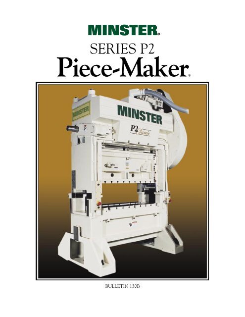
®MINSTER®<br />
SERIES P2<br />
®Piece-Maker®<br />
BULLETIN 130B
MINSTER®<br />
SERIES P2<br />
Au<strong>to</strong>matic Straight Side Presses<br />
Every operation involved in the building of a<br />
<strong>Minster</strong> Piece-Maker® press, from pouring of<br />
castings <strong>to</strong> final inspection, is based upon the<br />
determination <strong>to</strong> build the finest precision press.<br />
Because of this tradition, a <strong>Minster</strong> Piece-Maker<br />
gives superior performance, greater accuracy,<br />
higher production and longer die life, even under<br />
the most severe operating conditions.<br />
Parallelism between bolster and slide face is<br />
checked <strong>to</strong> determine that the precision alignment<br />
required on Piece-Maker presses has been<br />
maintained throughout all stages of construction.<br />
Also, vertical angularity of the slide throughout<br />
its entire stroke is checked left <strong>to</strong> right and front <strong>to</strong><br />
back. This kind of built-in quality is responsible<br />
for precision die alignment so necessary for<br />
successful progressive die stamping.<br />
2
❷<br />
❸<br />
❹<br />
❶<br />
❺<br />
3<br />
❽<br />
❻<br />
❾<br />
❼
❶<br />
❷<br />
❸<br />
❹<br />
Cast Construction Reduces<br />
Vibration.<br />
<strong>Minster</strong> Piece-Maker P2 Series au<strong>to</strong>matic production presses<br />
are of high tensile cast iron construction. Parts sections are<br />
properly proportioned for greatest strength without internal<br />
stresses. Various alloys are used for different cast parts<br />
depending upon their function. <strong>Minster</strong>’s cast construction<br />
is highly efficient in providing the compressive strength and<br />
vibration dampening requirements so essential in building<br />
a precision press for progressive die work -- particularly on<br />
heavy blanking jobs having high fracture loads. You get less<br />
punch wear, better die life and more part accuracy because<br />
the vibration is held <strong>to</strong> a minimum in a <strong>Minster</strong> Piece-Maker.<br />
Massive Bed Has Exceptional<br />
Rigidity.<br />
<strong>The</strong> superior design and quality construction of the<br />
P2 bed gives it the lowest possible deflection characteristics<br />
under constant impact and heavy load<br />
conditions <strong>to</strong> maximize <strong>to</strong>ol life and part quality.<br />
Oil troughs help contain die lubricants for recycling.<br />
Crown and Eccentric Shaft Provide<br />
Strength and Resist Deflection.<br />
<strong>The</strong> massive crown of the <strong>Minster</strong> Piece-Maker is engineered<br />
<strong>to</strong> maximize die life and part quality. Deep crown design backs<br />
up the eccentric shaft at any angle against forces created by<br />
the stamping application. Close-coupled load carrying plates<br />
evenly distribute these forces in<strong>to</strong> the crown structure.<br />
<strong>The</strong> forged steel eccentric shaft resists <strong>to</strong>rsional and bending<br />
deflection <strong>to</strong> enhance die parallelism. It is machined <strong>to</strong> a<br />
superb finish for excellent bearing fits and reduced stresses.<br />
<strong>The</strong> eccentric shaft eliminates the unsupported areas between<br />
main and connection bearings caused by the cheek thickness of<br />
the normal crankshaft. P2’s come standard with one extension.<br />
<strong>The</strong> main bearings of the P2 press give exceptional support<br />
<strong>to</strong> the eccentric shaft. Bearings are line bored for precise<br />
alignment. Crankshaft counterweights are standard on all<br />
flywheel drive P2’s.<br />
Main Bearing Support Block.<br />
This wedge-type support block is precision fitted<br />
between the main bearing caps and the <strong>to</strong>p of the<br />
uprights. <strong>The</strong>se supports help relieve the stresses<br />
placed on bearing cap screws by snap-thru forces and<br />
add <strong>to</strong> die life by stabilizing punch penetration.<br />
Tie Rods Aid Rigidity.<br />
Four-piece tie rod construction is used in all <strong>Minster</strong><br />
P2 frames. Massive steel tie rods are pre-stressed <strong>to</strong><br />
solidly hold the frame against off-center loading from<br />
progressive dies.<br />
4<br />
Normal Crankshaft<br />
Eccentric Shaft<br />
L+2T<br />
L<br />
L=Distance Between Bearings<br />
T=Thickness of Cheek
❼<br />
❽<br />
❺<br />
❻<br />
Heavy Slide and Connections.<br />
<strong>The</strong> P2 slide is of deep, heavily reinforced box-type construction,<br />
designed <strong>to</strong> withstand deflection <strong>to</strong> promote part quality and provide<br />
a large die area within the gibs. <strong>The</strong> massive upper connections easily<br />
transmit pressure through the working stroke. Lower connections<br />
have removable bronze saddle bushings. All P2 slides are arranged for<br />
one cross bar knockout as standard.<br />
Shutheight Adjustment & Indication.<br />
Included as standard is a digital shutheight meter that gives the<br />
opera<strong>to</strong>r a constant readout accurate <strong>to</strong> .001”. This feature aids the<br />
opera<strong>to</strong>r in accurate die setting procedures. <strong>The</strong> P2 offers powered<br />
slide adjustment for opera<strong>to</strong>r ease.<br />
PRESS SIZE P2-60 P2-100 P2-150 P2-200<br />
SLIDE ADJUSTMENT METHOD Flywheel Flywheel Geared Flywheel Geared Flywheel Geared<br />
Arranged for Detachable Air Wrench STD. STD. STD. Option Option Option Option<br />
Built-In ELECTRIC Mo<strong>to</strong>rized N/A Option Option STD. STD. STD. STD.<br />
Double Lock-Up w/Manual Adjustment Option Option N/A Option N/A Option N/A<br />
8-Point Gibbing for Precision Slide Guiding.<br />
Precision slide guiding is maintained by the close-<strong>to</strong>lerance 8-point gibbing<br />
arrangement. Front and rear gibs are accurately squared with the press bed and<br />
set for proper clearance by laminated spacers under each main gib bolt . . . thus<br />
eliminating trial and error adjustment.<br />
Front <strong>to</strong> back ways have fixed bronze wear plates, machined square<br />
with the slide face. Left <strong>to</strong> right ways are adjusted and supported their full<br />
length by tapered back-up bars. <strong>The</strong> extra-long gibs guide the slide fully within<br />
the gibs throughout the stroke -- even at maximum shutheight adjustments.<br />
This assures excellent slide-<strong>to</strong>-bed parallelism at all times, contributing <strong>to</strong> clean<br />
material fracture, high part accuracy, and increased die life. Slide and bolster are<br />
machined with standard T-Slots.<br />
Drive Arrangements for Maximum Press Efficiency.<br />
Flywheel type presses run at higher speeds and have shorter strokes<br />
for punching, notching, blanking and shallow forming or drawing<br />
operations on lighter materials. <strong>The</strong> Clutch and Brake Unit is<br />
mounted on the eccentric shaft within the flywheel. Flywheel rotates<br />
on anti-friction bearings. Flywheel brake is electrically interlocked<br />
with drive “S<strong>to</strong>p” circuit <strong>to</strong> eliminate “coasting.”<br />
Single Geared P2 presses incorporate<br />
helical gears for quiet operation, heavier<br />
material blanking, punching and deeper<br />
forming or drawing operations. <strong>The</strong><br />
Clutch and Brake Unit is mounted on<br />
the eccentric shaft within the main<br />
drive gear which rotates on anti-friction<br />
bearings. This arrangement provides<br />
a wider than normal speed range for a<br />
geared press.<br />
All <strong>Minster</strong> P2 presses use a variable<br />
frequency drive mo<strong>to</strong>r for long life and easy opera<strong>to</strong>r adjustment.<br />
An eddy-current drive mo<strong>to</strong>r is also available as an option<br />
5<br />
Flywheel Drive<br />
Geared Drive Mo<strong>to</strong>r is on rear as shown.
MINSTER® Moni<strong>to</strong>rFlow ... Continuous,<br />
Moni<strong>to</strong>red Press Lubrication.<br />
<strong>The</strong> patented <strong>Minster</strong> Moni<strong>to</strong>rFlow Pressurized Recirculating Oil Lubrication System supplies<br />
a continuous flow of filtered oil under pressure <strong>to</strong> all bearing surfaces ensuring reliable operation.<br />
It moni<strong>to</strong>rs both the flow <strong>to</strong> these points as well as oil level and pressure in the entire system. If a<br />
fault occurs, it protects the bearings by s<strong>to</strong>pping the press operation before damage happens.<br />
From the Manifold in the press crown, oil is channeled <strong>to</strong> bearings, gibs, gears, and<br />
counterbalances. Flow switches here moni<strong>to</strong>r oil flow <strong>to</strong> main and connection bearings and<br />
through sump line <strong>to</strong> reservoir. This protects against either broken or plugged lines.<br />
In the event of a lubrication fault, the Global Message Screen within the control instantly indicates<br />
which flow switch (or switches) signalled the fault, helping <strong>to</strong> pinpoint the problem area.<br />
❾ <strong>Minster</strong> Combination Air Friction Clutch Mechanical Options:<br />
and Brake Increases Die Life and Parts<br />
Production.<br />
This Single Unit, Au<strong>to</strong>matically Synchronized, combination, multiple disc clutch<br />
and brake has one moving member engaging the clutch by air pressure or applying<br />
the brake by spring pressure. Movement from full brake <strong>to</strong> complete engagement is<br />
approximately 1/16” assuring quick, controlled s<strong>to</strong>pping at any speed. Engagement<br />
on 360° friction surfaces remains constant throughout the stroke eliminating backlash<br />
after stamping and on the upstroke.<br />
Clutch Bumping Arrangement and Power Off Flywheel Barring<br />
are standard on flywheel type presses 100 <strong>to</strong>ns and smaller.<br />
Standard Electrical Features<br />
Production Management Control (PMC)<br />
This full featured press control was designed and integrated by<br />
<strong>Minster</strong> and incoporates all press functions including:<br />
• Full machine diagnostics detailing all press & feed line faults.<br />
• Selectable supervisor lockout for each function.<br />
• Clutch/Brake start-s<strong>to</strong>p.<br />
• Mo<strong>to</strong>r controls.<br />
• Tool s<strong>to</strong>rage.<br />
• Energy saver mode.<br />
• Preventative maintenance<br />
moni<strong>to</strong>ring.<br />
• Programmable Limit Switch.<br />
• Counters.<br />
• S<strong>to</strong>pping time indica<strong>to</strong>r.<br />
• Reason for recent s<strong>to</strong>p.<br />
• Crank position indica<strong>to</strong>r including distance off bot<strong>to</strong>m.<br />
<strong>The</strong> PMC utilizes open architecture which allows for greater<br />
convenience in planning and maintenance. It incorporates a PLC and<br />
color <strong>to</strong>uch screen technology; and, all press and feed line functions<br />
can be moni<strong>to</strong>red for efficient diagnosis of production line faults.<br />
ONNECT<br />
®<br />
This option provides detailed moni<strong>to</strong>ring of press room production equipment from remote<br />
locations and uses the industry standard network and database infrastructure. With an<br />
®<br />
ethernet-based local ONNECT<br />
area network and available Internet connectivity, the open architecture<br />
allows for integration in<strong>to</strong> non-PMC type control systems. <strong>The</strong> relational database allows for<br />
easy migration of data <strong>to</strong> other systems/applications. Feature views include: press summary;<br />
press detail; <strong>to</strong>ol s<strong>to</strong>rage; production his<strong>to</strong>ry; fault his<strong>to</strong>ry; dial-up access and support; HTML<br />
help, etc.<br />
6<br />
• Bolster Machining and<br />
Precision T-Slots.<br />
• Crossbar Knockout Parts.<br />
• Detachable Air Slide<br />
Adjustment Wrench.<br />
• Press Mounts.<br />
• Die Cushions.<br />
• Die Safety Block.<br />
• Special Paint.<br />
Available popular options include:<br />
• Additional <strong>to</strong>ol s<strong>to</strong>rage.<br />
• Die protection with Au<strong>to</strong> Tune<br />
technology.<br />
• Load Moni<strong>to</strong>ring.<br />
• Au<strong>to</strong>matic shutheight and<br />
counterbalance control.
<strong>Minster</strong> Series P2 Specifications & Dimensions<br />
(All Dimensions in Metric)<br />
Dimen. PRESS SIZE P2-60 P2-100 P2-150 P2-200<br />
DIMENSIONS COMMON TO ALL WIDTHS<br />
See Page 9 For Stroke/Speed Combinations.<br />
For a complete list of optional sizes and features such as die cushions and double lock-up for lamination<br />
machines, please talk with your <strong>Minster</strong> representative or contact <strong>Minster</strong> direct.<br />
7<br />
Flywheel Flywheel Single Flywheel Single Flywheel Single<br />
Type Type Geared Type Geared Type Geared<br />
Tons Capacity at Bot<strong>to</strong>m of Stroke 550 kN 910 kN 1350 kN 1800 kN<br />
Crankshaft Dia. @ Bearings/Min. Dia. of Eccentrics 100/145 125/170 165/235 180/235<br />
Crankshaft Extension (Standard): Length/Diameter 165/85 255/100 255/125 225/125<br />
Crankshaft Extension (Standard): Keyway Size . 20 x 10 20 x 10 30 x 15 30 x 15<br />
Adjustment of Slide: Standard Locking Arrangement 75 100 100 150<br />
A Shutheight on Bolster, S.D.A.U. (Standard Stroke 25 mm) 320 370 470 495<br />
A Shutheight on Bolster, S.D.A.U. (Standard Stroke 50 mm) 305 405 455 480<br />
A Shutheight on Bolster, S.D.A.U. (Standard Stroke 75 mm) 290 395 420 445<br />
A Shutheight on Bolster, S.D.A.U. (Standard Stroke 100 mm) 280 380 405 475 510<br />
A Shutheight on Bolster, S.D.A.U. (Standard Stroke 125 mm) 355 375 445 495<br />
A Shutheight on Bolster, S.D.A.U. (Standard Stroke 150 mm) 380 430 480<br />
A Shutheight on Bolster, S.D.A.U. (Standard Stroke 175 mm) 420<br />
A Shutheight on Bolster, S.D.A.U. (Standard Stroke 200 mm) 405<br />
B Thickness of Bolster Plate 90 125 150 175<br />
C Distance Floor <strong>to</strong> Top of Bed 865 915 1065 1065<br />
d/D Opening in Upright (Absolute Maximum) F-B 265/305 355/405 380/455 380/510<br />
M & N Opening in Leg (Exit Side) T-B x F-B 355 x 315 355 x 355 380 x 455 380 x 510<br />
Overall Height (Approximate) 2870 3405 3990 4115<br />
kW and Speed of Variable Speed Mo<strong>to</strong>r Drives 11,25/1800 15/1800 18/1200 or 18/1800 22/1200 or 22/1800<br />
Sliding Die Cushion -- Capacity 23 kN 87 kN 139 kN 139 kN<br />
WIDTH OF PRESS 1220 1525<br />
I & K Area of Slide: R-L x F-B 1220 x 585 1525 x 760<br />
J Distance Between Gibs 1270 1575<br />
E & F Area of Bolster and Bed: R-L x F-B 1220 x 1015 1525 x 1115<br />
G & H Opening in Bed: R-L x F-B 965 x 480 1370 x 445<br />
L Floor <strong>to</strong> Bot<strong>to</strong>m of Bed <strong>to</strong> Clear (Without Mounts) 355 305<br />
Floor Space Overall: R-L x F-B 2820x2335 2715x2310 3175x2390 3075x2465<br />
Weight (Lbs.) 21.150 22.950 30.150 32.400<br />
WIDTH OF PRESS 1220 1220 1525 1830<br />
I & K Area of Slide: R-L x F-B 1220 x 380 1220 x 470 1525 x 585 1830 x 760<br />
J Distance Between Gibs 1270 1270 1575 1880<br />
E & F Area of Bolster and Bed: R-L x F-B 1220 x 635 1220 x 785 1525 x 1015 1830 x 1115<br />
G & H Opening in Bed: R-L x F-B 1065 x 230 1040 x 380 1270 x 455 1525 x 455<br />
L Floor <strong>to</strong> Bot<strong>to</strong>m of Bed <strong>to</strong> Clear (Without Mounts) 340 305 355 305<br />
Floor Space Overall: R-L x F-B 2185x1370 2665x1525 2490x1830 3125x2335 3020x2310 3480x2385 3380x2465<br />
Weight (Lbs.) 8.910 12.690 13.770 23.400 25.650 30.600 32.400<br />
WIDTH OF PRESS 1525<br />
I & K Area of Slide: R-L x F-B 1525 x 470<br />
J Distance Between Gibs 1575<br />
E & F Area of Bolster and Bed: R-L x F-B 1525 x 785<br />
G & H Opening in Bed: R-L x F-B 1345 x 380<br />
L Floor <strong>to</strong> Bot<strong>to</strong>m of Bed <strong>to</strong> Clear (Without Mounts) 305<br />
Floor Space Overall: R-L x F-B 2970x1525 2795x1830<br />
Weight (Lbs.) 13.950 14.940
<strong>Minster</strong> Series P2 Specifications & Dimensions<br />
(All Dimensions in Inches)<br />
Dimen. PRESS SIZE P2-60 P2-100 P2-150 P2-200<br />
DIMENSIONS COMMON TO ALL WIDTHS<br />
See Page 9 For Stroke/Speed Combinations.<br />
For a complete list of optional sizes and features such as die cushions and double lock-up for lamination<br />
machines, please talk with your <strong>Minster</strong> representative or contact <strong>Minster</strong> direct.<br />
8<br />
Flywheel Flywheel Single Flywheel Single Flywheel Single<br />
Type Type Geared Type Geared Type Geared<br />
Tons Capacity at Bot<strong>to</strong>m of Stroke (U.S. Tons) 60 100 150 200<br />
Crankshaft Dia. @ Bearings/Min. Dia. of Eccentrics 4/5.75 5/6.75 6.5/9.25 7/9.25<br />
Crankshaft Extension (Standard): Length/Diameter 6/3.375 10/3.875 10/5.0 10/5.0<br />
Crankshaft Extension (Standard): Keyway Size . .75 x .375 .75 x .375 1.25 x .62 1.25 x .62<br />
Adjustment of Slide: Standard Locking Arrangement 3.0 4.0 4.0 6.0<br />
A Shutheight on Bolster, S.D.A.U. (Standard Stroke 1.0”) 12.5 14.5 18.5 19.5<br />
A Shutheight on Bolster, S.D.A.U. (Standard Stroke 2.0”) 12.0 16.0 18.0 19.0<br />
A Shutheight on Bolster, S.D.A.U. (Standard Stroke 3.0”) 11.5 15.5 16.5 17.5<br />
A Shutheight on Bolster, S.D.A.U. (Standard Stroke 4.0”) 11.0 15.0 16.0 18.75 20.0<br />
A Shutheight on Bolster, S.D.A.U. (Standard Stroke 5.0”) 14.0 14.75 17.5 19.5<br />
A Shutheight on Bolster, S.D.A.U. (Standard Stroke 6.0”) 15.0 17.0 19.0<br />
A Shutheight on Bolster, S.D.A.U. (Standard Stroke 7.0”) 16.5<br />
A Shutheight on Bolster, S.D.A.U. (Standard Stroke 8.0”) 16.0<br />
B Thickness of Bolster Plate 3.5 5.0 6.0 7.0<br />
C Distance Floor <strong>to</strong> Top of Bed 34 36 42 42<br />
d/D Opening in Upright (Absolute Maximum) F-B 10.5/12.0 14.5/16.0 19.0/20.0 21.0/22.0<br />
M & N Opening in Leg (Exit Side) T-B x F-B 14 x 12.5 14 x 14 15 x 18 15 x 20<br />
Overall Height (Approximate) 129 147 163 173<br />
HP and Speed of Variable Speed Mo<strong>to</strong>r Drives 15/1800 20/1800 25/1200 or 25/1800 30/1200 or30/1800<br />
Sliding Die Cushion -- Capacity 2.5 Tons 9.6 Tons 15.3 Tons 15.3 Tons<br />
WIDTH OF PRESS 48 60<br />
I & K Area of Slide: R-L x F-B 48 x 23 60 x 30<br />
J Distance Between Gibs 50 62<br />
E & F Area of Bolster and Bed: R-L x F-B 48 x 40 60 x 44<br />
G & H Opening in Bed: R-L x F-B 38 x 19 54 x 18<br />
L Floor <strong>to</strong> Bot<strong>to</strong>m of Bed <strong>to</strong> Clear (Without Mounts) 14 12<br />
Floor Space Overall: R-L x F-B 111 x 92 107 x 91 125 x 94 121 x 97<br />
Weight (Lbs.) 47,000 51,000 67,000 72,000<br />
WIDTH OF PRESS 48 48 60 72<br />
I & K Area of Slide: R-L x F-B 48 x 15 48 x 18.5 60 x 23 72 x 30<br />
J Distance Between Gibs 50 50 62 74<br />
E & F Area of Bolster and Bed: R-L x F-B 48 x 25 48 x 31 60 x 40 72 x 44<br />
G & H Opening in Bed: R-L x F-B 42 x 9 41 x 15 50 x 19 60 x 18<br />
L Floor <strong>to</strong> Bot<strong>to</strong>m of Bed <strong>to</strong> Clear (Without Mounts) 13.5 12 14 12<br />
Floor Space Overall: R-L x F-B 86 x 54 105 x 60 98 x 72 123 x 92 119 x 91 137 x 94 133 x 97<br />
Weight (Lbs.) 19,800 28,200 30,600 52,000 57,000 68,000 72,000<br />
WIDTH OF PRESS 60<br />
I & K Area of Slide: R-L x F-B 60 x 18.5<br />
J Distance Between Gibs 62<br />
E & F Area of Bolster and Bed: R-L x F-B 60 x 31<br />
G & H Opening in Bed: R-L x F-B 53 x 15<br />
L Floor <strong>to</strong> Bot<strong>to</strong>m of Bed <strong>to</strong> Clear (Without Mounts) 12<br />
Floor Space Overall: R-L x F-B 117 x 60 110 x 72<br />
Weight (Lbs.) 31,000 33,200
Speed/Stroke Combinations Standard<br />
PRESS<br />
Stroke<br />
NOTE<br />
P2-60 P2-100 P2-150 P2-200 P2-100 P2-150 P2-200<br />
Flywheel Flywheel Flywheel Flywheel Geared Geared Geared<br />
Std. Max. Std. Max. Std. Max. Std. Max. Std. Max. Std. Max. Std. Max.<br />
Speed Speed Speed Speed Speed Speed Speed Speed Speed Speed Speed Speed Speed Speed<br />
1.0” (25 mm) 450 600 350 500 300 450 300 400<br />
1.5” (38 mm) 400 500 300 450 300 400 300 350<br />
2.0” (50 mm) 375 400 300 400 250 350 250 300<br />
2.5” (64 mm) 350 375 250 350 220 300 220 275<br />
3.0” (75 mm) 300 350 250 300 200* 250 200* 250<br />
4.0” (100 mm) 200 300 160 250 150* 225 150* 225 120 150 120 150 120 150<br />
5.0” (125 mm) 160 200 150* 200* 150* 200* 100 150 100 150 100 150<br />
6.0” (150 mm) 150* 180* 90 120 90 120 90 120<br />
7.0” (175 mm) 90 120<br />
8.0” (205 mm) 90 120<br />
* Requires 1200 RPM Drive Mo<strong>to</strong>r.<br />
L<br />
A J<br />
NOTE: Specify Maximum and Minimum<br />
Feed Line Height From Bed.<br />
FRONT OF PRESS<br />
D K<br />
I<br />
9<br />
B<br />
C<br />
H<br />
E<br />
G<br />
d<br />
D<br />
N M<br />
END OF PRESS<br />
FACE OF SLIDE TOP OF BED<br />
F
1MPP303<br />
<strong>Minster</strong> Keeps Pace With Changing Standards and Regulations<br />
Presses shown, information, and references contained in this<br />
brochure, will not, in some cases, reflect latest recommendations<br />
of the ANSI B11.1 Standard, or certain Federal requirements<br />
as set down by the Occupational Safety and Health Act<br />
(OSHA). Illustrations of equipment are the most representative<br />
available at the time of publication of this literature. However,<br />
they may not depict design, required electrical controls,<br />
protective covers, etc., current at time of press shipment.<br />
Press electrical controls, protective covers, etc., supplied on any<br />
MINSTER press will, at all times, meet <strong>The</strong> <strong>Minster</strong> <strong>Machine</strong><br />
<strong>Company</strong>’s interpretations of applicable ANSI or Federal<br />
Requirements at the time of that Press’ shipment <strong>to</strong> its original<br />
®<br />
THE MINSTER MACHINE COMPANY<br />
MINSTER®<br />
Best In It’s Class!<br />
For More Information On <strong>The</strong><br />
<strong>Minster</strong> P2 Classic<br />
Consult Your <strong>Minster</strong> Representative<br />
or Contact <strong>Minster</strong> Direct.<br />
purchaser. Feed equipment covers are supplied by feed vendors<br />
<strong>to</strong> meet their interpretations of applicable ANSI Standards for<br />
press- mounted roll feeds.<br />
Complete compliance with the regulations of the Occupational<br />
Safety Act, by law, rests with the machine <strong>to</strong>ol purchaser. <strong>The</strong><br />
<strong>Minster</strong> <strong>Machine</strong> <strong>Company</strong> does not either imply or warrant,<br />
under any circumstances, that safeguarding is furnished<br />
for the point of operation which the user installs in this<br />
press component. It is the user alone who can make proper<br />
determination of the safeguarding needed for his use of the<br />
equipment at the point of operation and from related hazards<br />
<strong>to</strong> the extent they may exist.<br />
240 WEST FIFTH STREET • MINSTER, OHIO 45865-0120 U.S.A. • PHONE: (419) 628-2331 • FAX: 419-628-3517<br />
www.minster.com<br />
<strong>Minster</strong> Has Sales and Service Offices Located Throughout the World<br />
Contact <strong>Minster</strong> Direct For <strong>The</strong> Name of Your Global Representative