Illuminator E & IE Catalog PDF - Myers Power Products, Inc.
Illuminator E & IE Catalog PDF - Myers Power Products, Inc.
Illuminator E & IE Catalog PDF - Myers Power Products, Inc.

Create successful ePaper yourself
Turn your PDF publications into a flip-book with our unique Google optimized e-Paper software.
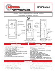
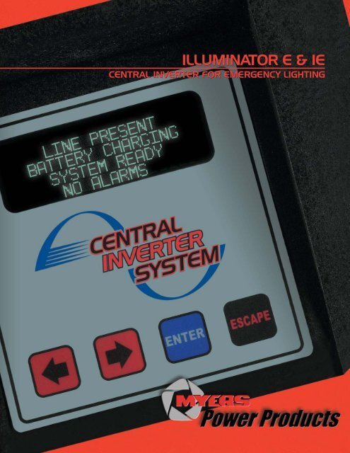
ILLUMINATOR E & <strong>IE</strong><br />
CENTRAL INVERTER FOR EMERGENCY LIGHTING
1<br />
THE THE ILLUMINA ILLUMINATOR<br />
ILLUMINA TOR<br />
ILLUMINATOR SER<strong>IE</strong>S <strong>IE</strong><br />
The <strong>Illuminator</strong> Series <strong>IE</strong> is an interruptible lighting inverter. It<br />
transfers to inverter mode (battery power) when utility power is<br />
interrupted for more than one line cycle. This series is capable<br />
of supporting full normally off load. The Series <strong>IE</strong> is designed<br />
for fluorescent, quartz, LED, and incandescent normally on<br />
and/or normally off lighting loads and applications that<br />
require large normally off (emergency only) lighting loads.<br />
SER<strong>IE</strong>S E<br />
SER<strong>IE</strong>S <strong>IE</strong><br />
APPLICA APPLICA APPLICATIONS<br />
APPLICA APPLICATIONS<br />
TIONS<br />
H.I.D.<br />
Compatible<br />
Yes<br />
ILLUMINATOR SER<strong>IE</strong>S E<br />
The <strong>Illuminator</strong> Series E is an uninterruptible lighting inverter.<br />
It transfers to inverter mode (battery power) when utility power<br />
is interrupted for less than 1mS. The line inter-active design<br />
eliminates excessive transfers to battery power. The Series E<br />
is designed for HID lighting loads, mixed HID/incandescent/<br />
quartz/LED/fluorescent normally on loads and applications<br />
that do not require large normally off (emergency only) loads.<br />
V.T.D.<br />
Available<br />
Line<br />
Interactive<br />
No Yes<br />
No Yes<br />
No<br />
• 911 Facilities<br />
• Airports<br />
• Apartment/Condominium Complexes<br />
• Assisted Living Centers, Nursing Homes<br />
• Banks, Financial Institutions<br />
• Casinos<br />
• City, County, State, Federal Buildings<br />
• Grocery Stores/Home Center Stores<br />
• Hospitals<br />
• Hotel, Motels<br />
• Industrial<br />
• Medical Offices<br />
• Military Complexes<br />
• Movie/Performing Art Theaters<br />
• Office Buildings<br />
• Parking Garages<br />
• Prisons<br />
• Race Tracks<br />
• Railroad, Subway, Bus Stations<br />
• Religious Facilities<br />
• Restaurants<br />
• Retail Department Stores<br />
• Schools, Colleges, Day Care Centers<br />
• Shopping Malls<br />
• Sport Facilities<br />
• Toll Booths<br />
• Tunnels and Bridges<br />
Norm. Off<br />
Load Capability<br />
20% Maximum of<br />
System Capacity<br />
Full System<br />
Capacity<br />
• Designed to work with all electronic power factor<br />
corrected ballasts.<br />
• Central Inverters can eliminate unit equipment in<br />
architecturally sensitive applications.<br />
• Eliminate maintenance costs of individual testing of unit<br />
equipment and battery powered ballasts. All tests and<br />
diagnostics are performed and recorded automatically.
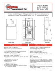
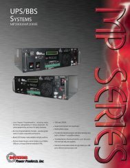
Industrial Grade Enclosure<br />
Input Breaker<br />
Input Terminal<br />
Block<br />
Front Access<br />
Batteries<br />
Powder-Coat<br />
Paint<br />
INVERTER<br />
Fourth generation IGBT-based inverter with dynamic pulse-bypulse<br />
current limiting and inrush protection. Short circuit and<br />
overload protected by microprocessor and PWM integration for<br />
maximum reliability.<br />
WAVEFORM<br />
Pure PWM sine wave, less than 3% THD with 0.5 leading and<br />
0.5 lagging loads. Microprocessor and crystal controlled.<br />
THERMAL PERFORMANCE<br />
Bonded fin heat sink technology for maximum thermal<br />
performance. Fan energized only on inverter mode which<br />
increases reliability and reduces preventative maintenance.<br />
BATTERY CHARGER<br />
Integrated 3 step with equalize, temperature controlled, 24hour<br />
recharge for 90 minute system is standard.<br />
MODULAR<br />
Innovative modular sub-assembly design leads the industry<br />
with less than 15 minute MTTR.<br />
6.0 - 16.7kVA shown.<br />
SYSTEM SYSTEM DESIGN DESIGN FEA FEATURES<br />
FEA TURES<br />
Battery Fuse<br />
User Interface<br />
Display<br />
Output<br />
Distribution<br />
3-Point<br />
Corbin 60<br />
Locking Latch<br />
Installation<br />
Switch<br />
Battery Terminal<br />
Block<br />
CONSTRUCTION<br />
Enclosure is cold-rolled steel with powder-coated surface.<br />
Hinged doors with security 3-point Corbin 60 locking system<br />
for easy access and maintenance.<br />
BATTER<strong>IE</strong>S<br />
Front access, maintenance-free, sealed lead calcium VRLA<br />
batteries are standard. Significantly reduces installation and<br />
maintenance time and increases safety.<br />
SMALL FOOTPRINT<br />
25" (depth) x 30" (wide) 1.5 - 5kVA, or 25" (depth) x 48" (wide)<br />
6 - 16.7kVA.<br />
CONTROL PANEL<br />
Self-testing and self-diagnostics per NFPA and UL standards.<br />
Memory logs of over 1525 parameters contained in Test, Event<br />
and Fault Logs. Easy to read alpha-numeric display with userfriendly<br />
keypad integrates Systems’ Meter, Alarm, Control and<br />
Program functions.<br />
2
3<br />
SYSTEM SYSTEM DISPLA DISPLAY DISPLA Y FUNCTIONS<br />
FUNCTIONS<br />
NOTE: All displayed meter functions match the inverter.<br />
SYSTEM SYSTEM OPTIONS OPTIONS<br />
OPTIONS<br />
E-MAIL/MODEM<br />
User can enable/disable and program alarms that will trigger<br />
messages to e-mail destinations. User can set up specific alarm<br />
events that will alert service or maintenance personnel. The system<br />
will transmit monthly and yearly tests per NFPA requirements. Bidirectional<br />
communication eases system diagnostics and data<br />
retrieval through the RS-232 serial communication port.<br />
TIME DELAY<br />
Delays retransfer of inverter to continue supplying emergency<br />
power to the normally off output for 15 minutes after the return of<br />
utility power.<br />
OUTPUT CIRCUIT BREAKER<br />
Maximum output breakers available: 12 unsupervised (1-pole),<br />
8 supervised (1-pole) for 1.5 - 5 kVA, and 24 unsupervised (1-pole),<br />
15 supervised (1-pole) for 6 - 16.7 kVA. Additional output breakers<br />
available on 1.5 - 5kVA systems (additional 30 pole positions,<br />
42 positions total; enclosure height increases to 62”).<br />
OUTPUT TRIP ALARM<br />
An audible and visual alarm activates when an output distribution<br />
circuit breaker is open or has tripped.<br />
MAINTENANCE BYPASS<br />
This device is internally mounted in the system and permits<br />
maintenance personnel to easily bypass the inverter and connect<br />
directly to the AC utility power. The “make before break” switch<br />
isolates the electronics or inverter system to allow performance of<br />
routine maintenance or servicing.<br />
REMOTE METER PANEL<br />
Allows a second fully functional front meter panel to be mounted<br />
external to the inverter up to 150 feet away. (100’ cable<br />
standard)<br />
BA BATTERY BA TTERY OPTIONS<br />
OPTIONS<br />
S - BATTERY (Sealed Lead-Calcium) (Standard)<br />
A maintenance free, valve regulated lead calcium battery.<br />
Constructed with a rugged polypropylene case. Does not<br />
require any special room ventilation. 10-year prorated<br />
warranty.<br />
METER FUNCTIONS<br />
• AC Voltage Input • Battery Current<br />
• AC Voltage Output • VA Output<br />
• AC Current Output • Inverter Watts<br />
• Battery Voltage • Ambient Temperature<br />
• System Days • Inverter Minutes<br />
PROGRAM FUNCTIONS<br />
• Set Date • Set Low Battery Alarm<br />
• Set Time • Set Near Low Battery Alarm<br />
• Set Month Test Date/Time • Set Low AC Voltage Alarm<br />
• Set Yearly Test Date/Time • Set High AC Voltage Alarm<br />
• Set Load Fault Reduction Setting • Set Ambient Temperature Alarm<br />
CONTROL FUNCTIONS<br />
• Test Log & Event Log • Alarm Log (75 Logs Stored):<br />
(75 Logs Stored): Date, Time, Date, Time, Alarm Type<br />
Duration, Output Voltage, • Test<br />
Output Current, Ambient<br />
Temperature and Alarms Present<br />
• Buzzer On/Off<br />
SUMMARY FORM C CONTACTS<br />
Form “C” contacts rated at 5 amps maximum at 25OVAC/<br />
3OVDC. Dry contacts will change state when any system alarm<br />
activates. Contacts change state with the following alarms: High/<br />
low battery charger fault, near low battery, low battery, load<br />
reduction fault, output overload, high/low AC input volts, high<br />
ambient temperature, inverter fault, test failure, and optional<br />
circuit breaker trip alarm.<br />
FAST CHARGE<br />
This is a battery charger upgrade which decreases the time to<br />
recharge a fully discharged battery bank to a full charge. The<br />
recharge time is decreased from the standard 24-hour period to a<br />
12-hour period.<br />
NORMALLY OFF OUTPUT (Standard on Series <strong>IE</strong>)<br />
This output circuit is dedicated for emergency-only equipment.<br />
Emergency-only equipment operates during power outages and<br />
when the system is on battery back up. This option leaves the<br />
selective load circuits off during normal utility power conditions.<br />
REMOTE SUMMARY ALARM PANEL<br />
A wall mountable box containing an audible alarm and light that<br />
will activate upon any system alarm with silence switch.<br />
INVERTER ON FORM C CONTACT<br />
Form “C” dry contacts that will change state when the inverter<br />
transfers to battery operation.<br />
STATUS MONITORING CONTACTS<br />
Form “C” dry contacts capable of monitoring system and<br />
option statuses (Inverter On, Inverter Off, AC Present, High<br />
Temperature, Summary Alarm, System Bypass*, and OTA*)<br />
*Requires purchase of Maintenance Bypass and/or Output<br />
Trip Alarm options.<br />
G - BATTERY (Sealed Lead-Calcium)<br />
A maintenance free, long life, valve regulated lead calcium<br />
battery. Constructed with a polypropylene jar installed in a<br />
steel container. Does not require any special room ventilation.<br />
20-year prorated warranty.
SYSTEM TYPE<br />
E - <strong>Illuminator</strong> Series “E”<br />
<strong>IE</strong> - <strong>Illuminator</strong> Series “<strong>IE</strong>”<br />
VOLTAGE (INPUT/OUTPUT) 1<br />
1 - 120-120<br />
2 - 120-120/277<br />
3 - 208-120<br />
4 - 240-120/240<br />
5 - 277-120<br />
6 - 277-277<br />
7 - 277-277/120<br />
8 - 208-120/240<br />
9 - 347-347<br />
A - 208-120/208<br />
Z - Other Voltages<br />
KVA/KW 2<br />
1 -1.5<br />
2 - 2.25<br />
3 - 3.0<br />
4 - 3.75<br />
5 - 5.0<br />
6 - 6.0<br />
7 - 8.0<br />
8 - 10.0<br />
9 - 12.5<br />
10 - 16.7<br />
Example Model Number:<br />
1-E-4-S-BA2007-F-T-S-M-N-2YW<br />
BATTERY TYPE<br />
S - Standard (VRLA)<br />
G - VRLA 20-Year<br />
1) Only single phase voltages available.<br />
2) KVA = KW<br />
3) Standard battery run time is 90 minutes.<br />
4) Normally off loads on Series E cannot exceed 20% of total KVA<br />
rating with any combination of H.I.D. Loads.<br />
5) Maximum output breakers available: 12 unsupervised (1-pole), 8<br />
supervised (1-pole) for 1.5 - 5 kVA, and 24 unsupervised (1-pole),<br />
15 supervised (1-pole) for 6 - 16.7 kVA. Breakers provided are 20<br />
Amps unless specified otherwise. A 2-pole breaker occupies 2<br />
positions.<br />
6) Maintenance bypass switch is a “make before break”.<br />
7) Standard one year warranty.<br />
8) Requires Factory Start-up and E-mail/Modem options. This<br />
program will provide monitoring of the lighting inverter system by<br />
our factory service department. All monthly and yearly system<br />
tests will be reviewed by our factory service department for early<br />
warning signs of any system malfunction. Any system alarms and<br />
monthly/yearly test results will automatically be E-mailed to our<br />
service department where corrective action can be taken and<br />
while under warranty, if necessary, a factory authorized service<br />
technician will be scheduled to complete any necessary repairs.<br />
This monitoring program will require a dedicated telephone line.<br />
9) 15 minute retransfer time delay of normally off circuit after return<br />
of utility.<br />
RUNTIME 3<br />
(Other than 90 minutes)<br />
R15 - 15 Minutes<br />
R30 - 30 Minutes<br />
R60 - 60 Minutes<br />
R120 - 120 Minutes<br />
R180 - 180 Minutes<br />
R240 - 240 Minutes<br />
OUTPUT BREAKERS 5<br />
Example: B A 20 07<br />
OUTPUT<br />
B - Normally On<br />
N - Normally Off 4<br />
VOLTAGE<br />
A - 120<br />
B - 208<br />
C -240<br />
D - 277<br />
Z - Other<br />
AMP RATING<br />
10, 15, 20, 25,<br />
30, 40, 50, 60<br />
QUANTITY<br />
01 - 24 5<br />
(List all circuit breaker<br />
requirements separately,<br />
ex: BA2007 - NA1001 )<br />
ORDERING ORDERING GUIDE<br />
GUIDE<br />
WARRANTY 7<br />
2YW - Factory Start-Up<br />
Extended 2-Year<br />
Warranty<br />
5YP - 5-Year Preventative<br />
Maintenance Plan,<br />
Start-Up <strong>Inc</strong>luded<br />
5YW - 5-Year Extended<br />
Electronics Warranty<br />
SMP 8 - Service Monitoring<br />
Plan<br />
OPTIONS<br />
A - Remote Summary<br />
Alarm Panel<br />
C - Status Monitoring Contacts<br />
Alarm Panel<br />
E - E-Mail Modem<br />
F - Fast Charge<br />
I - Inverter On Dry Contact<br />
M - Maintenance Bypass 6<br />
N - Normally Off Output<br />
(Std. on <strong>IE</strong>) 4<br />
R - Remote Meter Panel<br />
S - Summary Fault<br />
Form C Contacts<br />
T - Output Trip 5<br />
(Supervised) Alarm<br />
V - Time Delay 15 min.<br />
(Series <strong>IE</strong> only) 9<br />
Z - Seismic Zone 4<br />
ACCESSOR<strong>IE</strong>S<br />
MOD - Modem<br />
EMBP A,6- External Maintenance Bypass Switch<br />
A) Cannot purchase External Maintenance Bypass Switch with<br />
Branch Circuit Breaker options.<br />
4
5<br />
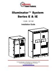
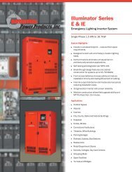
SYSTEM SYSTEM SPECIFICA<br />
SPECIFICATIONS<br />
SPECIFICA<br />
SPECIFICA TIONS<br />
76"<br />
25"<br />
ELECTRONICS MODULE<br />
<strong>Power</strong> Rating (kVA)<br />
<strong>Power</strong> Rating (kW)<br />
48"<br />
6.0 - 16.7kVA<br />
Efficiency (@ full load)<br />
Audible Noise (dBA @ 1m)<br />
Heat Loss (BTU)/HR<br />
BATTER<strong>IE</strong>S<br />
(90 Minutes @ Full Load)<br />
Number of Batteries<br />
Voltage (VDC)<br />
Current (Amperes)<br />
Cabinet Dimensions<br />
Total<br />
90 Minute<br />
System<br />
Width Height Depth Weight Batteries<br />
Weight<br />
in/cm in/cm in/cm lbs/kg lbs/kg lbs/kg<br />
1.5 1.5 98 45 102 30/77 47/119 25/64 215/98 296/135 4 48 39 511/230<br />
2.25 2.25 98 45 153 30/77 47/119 25/64 230/105 444/200 6 72 38 674/306<br />
3.0 3.0 98 45 204 30/77 47/119 25/64 235/107 592/266 8 96 38 827/372<br />
3.75 3.75 98 45 255 30/77 47/119 25/64 240/109 740/330 10 120 37 980/441<br />
5.0 5.0 98 45 340 30/77 47/119 25/64 280/128 888/400 12 144 41 1168/525<br />
6.0 6.0 98 45 408 48/122 76/193 25/64 605/272 1110/500 15 180 40 1715/772<br />
8.0 8.0 98 45 544 48/122 76/193 25/64 640/288 1480/666 20 240 39 2120/954<br />
10.0 10.0 98 45 680 48/122 76/193 25/64 785/353 1776/800 24 144 82 2561/1153<br />
12.5 12.5 98 45 850 48/122 76/193 25/64 805/362 2220/999 30 180 82 3025/1361<br />
16.7 16.7 98 45 1135 48/122 76/193 25/64 885/398 2960/1332 40 240 80 3845/1730<br />
30"<br />
1.5 - 5kVA<br />
25"<br />
47"
INPUT<br />
OUTPUT<br />
BATTERY<br />
ENVIRONMENTAL<br />
GENERAL<br />
PHYSICAL<br />
SYSTEM SYSTEM SPECIFICA<br />
SPECIFICATIONS<br />
SPECIFICA TIONS<br />
Voltage 120 or 277VAC 1-phase 2-wire +10% -20% on Series E,<br />
and +10% -15% on Series <strong>IE</strong>. Contact factory for all other voltages.<br />
Input <strong>Power</strong> Walk-in Limiting inrush current to less than 125% of full rated load.<br />
Input Frequency 60Hz, +/- 3%.<br />
Synchronizing Slew Rate 1Hz per second nominal.<br />
Protection Input Circuit Breaker.<br />
AIC Rating 65k RMS symmetical ampere short-circuit rating.<br />
<strong>Power</strong> Factor 0.5 lag/lead.<br />
Voltage 120 or 277VAC 1-phase 2-wire. Contact factory for all other voltages.<br />
Static Voltage Load current change +/-2%, battery discharge +/-12.5%<br />
Dynamic Voltage +/- 2% for +/-25% load step change, +/-3% for a 50% load step change,<br />
recovery within 3 cycles.<br />
Harmonic Distortion < 3% THD for linear load.<br />
Overload Fuse protected.<br />
Output Frequency 60Hz +/- 0.05Hz during emergency mode.<br />
Load <strong>Power</strong> Factor 0.5 lag to 0.5 lead.<br />
Inverter Overload 115% for 10 minutes. 150% for 16 line cycles.<br />
Protection Optional Distribution Circuit Breakers.<br />
Type Valve-regulated sealed lead-calcium; Consult factory for additional<br />
battery types.<br />
Charger Microprocessor controlled for various battery types and temperature<br />
compensating (recharge per UL924 spec).<br />
Protection Automatic low-battery disconnect; automatic restart upon utility return.<br />
Disconnect Fuse<br />
Optional Runtimes Extended runtimes available. Consult factory for additional information.<br />
Operating Temperature 20° to 30°C (68° to 86°F) per UL 924.<br />
Storage Temperature -20° to 70°C (-68° to 158°F) (electronics only).<br />
Relative Humidity < 95% (non-condensing)<br />
Effeciency 98% while on utility.<br />
Design PWM inverter type utilizing IGBT technology with 2mS transfer time on Series E<br />
and 50mS on Series <strong>IE</strong>.<br />
Output Circuits Series E - Normally On Circuit standard; Normally Off Circuit optional. Series <strong>IE</strong><br />
- Normally On and Normally Off Circuits standard.<br />
Generator Input Compatible with generators.<br />
Control Panel Microprocessor controlled 4 x 20-character vacuum fluorescent display with<br />
touchpad controls/functions scrolling system status.<br />
Metering Input & Output Voltage, Battery Voltage, Battery & Output Current, Output VA,<br />
Temperature, Inverter Wattage.<br />
Alarms High/Low Battery Charger Fault, Near Low Battery, Low Battery, Load Reduction<br />
Fault, Output Overload, High/Low AC Input Volts, High Ambient Temperature,<br />
Inverter Fault, Output Fault, Test Failure, and Optional Circuit Breaker Trip.<br />
Communications RS-232 port (DB9 standard). E-mail/fax modem optional.<br />
Manual Maintenance Bypass Optional internal or optional external without internal distribution breakers.<br />
Alarm Contacts Optional Summary Alarm Form "C" Contacts.<br />
Warranty 1 year standard warranty includes all parts, labor, & travel expenses within<br />
48 contiguous states. 10 years prorated warranty on batteries. Extended<br />
warranties, preventative maintenance and customized service plans<br />
are available.<br />
Factory Start-up Purchase factory start-up & receive 1 additional year of electronics warranty.<br />
5-Year Maintenance Plan Purchase 5-year preventative maintenance plan & receive free factory start-up.<br />
Cabinet Freestanding NEMA Type 1.<br />
Cooling Forced Air, during emergency mode.<br />
Cable Entry Top or sides on 1.5 - 5kVA; Sides only on 6 - 16.7kVA.<br />
Access Front.<br />
6
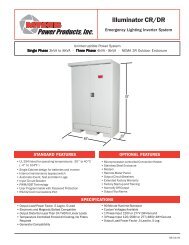
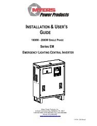
ALSO AVAILABLE<br />
FROM<br />
MYERS POWER<br />
PRODUCTS:<br />
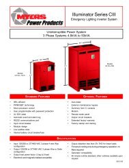
ILLUMINATOR SER<strong>IE</strong>S CIII<br />
4.8 kVA TO 50 kVA THREE PHASE<br />
ILLUMINATOR CM<br />
500 VA TO 2000 VA SINGLE PHASE<br />
44 South Commerce Way • Bethlehem, PA 18017<br />
Tel: (800) 526-5088 • Fax: (610) 868-8686<br />
www.myerspowerproducts.com<br />
ELP-0001-BR-0610