DDC 1 Angela Guo ModelCoordinationReport

Create successful ePaper yourself
Turn your PDF publications into a flip-book with our unique Google optimized e-Paper software.
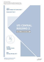
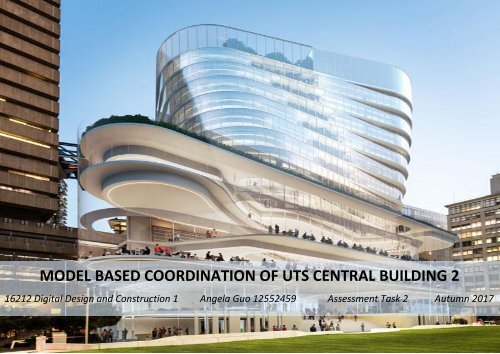
MODEL BASED COORDINATION OF UTS CENTRAL BUILDING 2<br />
16212 Digital Design and Construction 1 <strong>Angela</strong> <strong>Guo</strong> 12552459 Assessment Task 2 Autumn 2017
16212 DIGITAL DESIGN AND CONSTRUCTION 1 MODEL COORDINATION<br />
Table of Contents<br />
Model Federated Outcome ............................................................................................................................................................................................................. 3<br />
Model Overview ........................................................................................................................................................................................................................... 4<br />
Visualisation of Models ............................................................................................................................................................................................................ 5<br />
Visual Hotspot Checks ................................................................................................................................................................................................................... 13<br />
Level 08 Hotpots ........................................................................................................................................................................................................................ 14<br />
Roof Level Hotspots ............................................................................................................................................................................................................... 16<br />
Level 08 Interferences Check ........................................................................................................................................................................................................ 18<br />
Automated Critical Elements Check ........................................................................................................................................................................................... 19<br />
Automated Services Check .................................................................................................................................................................................................... 31<br />
Significant Clash ...................................................................................................................................................................................................................... 35<br />
Roof Level Interference Check ...................................................................................................................................................................................................... 36<br />
Automated Critical Elements Check ........................................................................................................................................................................................... 37<br />
Automated Services Check .................................................................................................................................................................................................... 40<br />
Significant Clash ...................................................................................................................................................................................................................... 41<br />
Key Findings and Recommendation ............................................................................................................................................................................................. 42<br />
Key Findings ............................................................................................................................................................................................................................... 43<br />
Recommendations/Conclusion .............................................................................................................................................................................................. 44<br />
Appendices .................................................................................................................................................................................................................................... 45<br />
Page | 1
16212 DIGITAL DESIGN AND CONSTRUCTION 1 MODEL COORDINATION<br />
Executive Summary<br />
Background<br />
This report is a Model Based Coordination on University of Technology, Sydney Building 2. A federated BIM model is used to analyse the detailed<br />
design, building dimensions and conflicts between disciplines. An innovative tool that will be used for clash detection and resolution is<br />
Navisworks. Navisworks allows the project to be designed and controlled with advance coordination and 5D examination for it to be delivered<br />
flawlessly. The efficient clash detection on Navisworks allows design collisions and error to be identified early before drawings are completed.<br />
This reduces the risk of delay and additional cost to fix the error during construction. Hence, this model based coordination will be done on<br />
Navisworks for maximum quality of design.<br />
Purpose<br />
The purpose of this report is to document the following:<br />
1. Top 3 hot spot issues in Level 8 and Roof Level with suggested actions, disciplines involved, level of severity, and description of hot spots.<br />
2. Top 2 interference check per discipline of Structure against all five services discipline in Level 08 and Roof level with identification of<br />
severity, recommendation in resolving the issue, and identification of affected disciplines involved in the clash.<br />
3. Top 2 interference check per discipline of Architecture against all five services discipline in Level 08 and Roof level with identification of<br />
severity, recommendation in resolving the issue, and identification of affected disciplines involved in the clash.<br />
4. Top 2 clashes per service discipline in Level 08 and Roof Level with identification and analysis of root cause.<br />
5. Identification of one significant clash that cannot be grouped in both Level 08 and Roof Level, and recommendations in resolving the<br />
clash issues.<br />
6. Key findings in the model coordination.<br />
7. Overall recommendation to improve the quality and efficiency of the model.<br />
Methodology<br />
The tool that will be used to identify issues and resolution is through Navisworks which enables the eight discipline models to be imported into<br />
a single platform to analyse the model, conduct clash detection, and identify hot spots.<br />
Page | 2
16212 DIGITAL DESIGN AND CONSTRUCTION 1 MODEL COORDINATION<br />
PART I: FEDERATED MODEL OUTCOME<br />
Project Overview<br />
Visualisation of Federated Model, Discipline Model, and Allocated Level<br />
Page | 3
16212 DIGITAL DESIGN AND CONSTRUCTION 1 MODEL COORDINATION<br />
Project Overview<br />
Project Name: Building 2 – UTS Central Project<br />
Project Address: 15 Broadway Street Ultimo NSW 2007<br />
Client Name: University of Technology Sydney<br />
Date of Audit: 07 April 2017<br />
Model Summary<br />
UTS BIM Model and Co-ordination<br />
Federated Model File Name Size Revision Download Date<br />
Co-ordination Model GUO_BUILDING3.0 747 KB Revision 55 07/04/2017<br />
Discipline Models File Name Size Revision Date Modified<br />
Architectural<br />
CB02__A-FJMT-Architecture- 7.49 MB Revision 1 07/04/2017<br />
Facade CB02__A-FJMT-Facade-IFC[AE] 10.9 MB Revision 1 07/04/2017<br />
Structure CB02 Structure IFC2x3 2.13 MB Revision 1 07/04/2017<br />
Mechanical<br />
CB02_M-SVA-Mechanical- 9.84 MB Revision 1 07/04/2017<br />
Hydraulic Pressure RVT[AA] CB02__H-ERB-Pressure- 4.89 MB Revision 1 07/04/2017<br />
Hydraulic Drainage NWC[O] CB02__H-ERB-Drainage- 4.30 MB Revision 1 07/04/2017<br />
Electrical<br />
CB02_E-JHA-Electrical-NWC 1.25 MB Revision 1 07/04/2017<br />
Fire [AC] CB02__R-ERB-Fire-NWC[O] 15.3 MB Revision 1 07/04/2017<br />
Page | 4
16212 DIGITAL DESIGN AND CONSTRUCTION 1 MODEL COORDINATION<br />
Visualizations of overall federated model, discipline models, and Level 08<br />
Page | 5
16212 DIGITAL DESIGN AND CONSTRUCTION 1 MODEL COORDINATION<br />
Structural Federated Model – NORTH WEST PERSPECTIVE<br />
Page | 6
16212 DIGITAL DESIGN AND CONSTRUCTION 1 MODEL COORDINATION<br />
Architectural Federated Model – SOUTH EAST PERSPECTIVE<br />
Page | 7
16212 DIGITAL DESIGN AND CONSTRUCTION 1 MODEL COORDINATION<br />
Hydraulic Drainage and Pressure Federated Model – SOUTH WEST PERSPECTIVE<br />
Page | 8
16212 DIGITAL DESIGN AND CONSTRUCTION 1 MODEL COORDINATION<br />
Fire System Federated Model – NORTH EAST PERSPECTIVE<br />
Page | 9
16212 DIGITAL DESIGN AND CONSTRUCTION 1 MODEL COORDINATION<br />
Electrical Federated Model – North East Perspective<br />
Page | 10
16212 DIGITAL DESIGN AND CONSTRUCTION 1 MODEL COORDINATION<br />
Mechanical Federated Model – North East Perspective<br />
Page | 11
16212 DIGITAL DESIGN AND CONSTRUCTION 1 MODEL COORDINATION<br />
Allocated Level 08 – North East Perspective<br />
Page | 12
16212 DIGITAL DESIGN AND CONSTRUCTION 1 MODEL COORDINATION<br />
PART II: VISUAL HOTSPOT CHECKS ON LEVEL 08 AND ROOF LEVEL<br />
A visual hotspot check is a fundamental skill in identifying quality issues of design and construction that cannot be detected using<br />
Autodesk software such as Naviswork Manage and Revit. It is essential in inspecting the project disciplines to ensure they comply<br />
with the Building Codes of Australia as BIM software cannot detect designs that have breached the codes. Although, manual hotspot<br />
checks limited from the capability of detecting if one building service had the same quality issue or not. This resulted to additional<br />
time used to check every service before moving onto the next discipline.<br />
Page | 13
16212 DIGITAL DESIGN AND CONSTRUCTION 1 MODEL COORDINATION<br />
VISUAL HOTSPOT CHECKS<br />
Item<br />
No<br />
Location Model Image Clash<br />
Type<br />
1.0 Level 08<br />
Hard<br />
LEVEL 08<br />
Description/Root<br />
Cause<br />
The fire steel pipe<br />
is protruding<br />
from the<br />
suspended<br />
plasterboard<br />
ceiling. The fire<br />
pipe shows no<br />
connection to any<br />
other services<br />
and it has no<br />
covering which<br />
makes it a hazard.<br />
Suggested Action<br />
This hotspot is not<br />
only an interference<br />
issue but also a<br />
quality risk. As the<br />
pipes come so low<br />
down from the<br />
ceiling and it is not<br />
concealed, this is a<br />
safety hazard for the<br />
people within the<br />
building. It is<br />
therefore suggested<br />
for the fire pipe to<br />
be eliminated since<br />
it has no connection<br />
to other services.<br />
Assigned<br />
To<br />
Assigned<br />
to<br />
hydraulic<br />
engineer<br />
while also<br />
notifying<br />
the<br />
changes to<br />
fire<br />
technician.<br />
Severity of<br />
Clash<br />
Severity is low<br />
due to the<br />
pipes showing<br />
no connection<br />
to other<br />
building<br />
services,<br />
which makes<br />
it easily<br />
rectified by<br />
simply<br />
removing the<br />
pipe.<br />
A<br />
Structural<br />
building<br />
element<br />
B<br />
Hydraulic<br />
pressure<br />
building<br />
element<br />
Page | 14
16212 DIGITAL DESIGN AND CONSTRUCTION 1 MODEL COORDINATION<br />
1.2 Level 08<br />
Hard<br />
Structural<br />
concrete beam<br />
intersecting with<br />
the Mechanical<br />
BMA rectangular<br />
duct.<br />
By lifting the<br />
concrete slab above<br />
the concrete beam<br />
0.200m higher, it<br />
can allow clearance<br />
for the beam to be<br />
lifted as well. This<br />
will avoid the<br />
interference of the<br />
mechanical duct and<br />
the concrete beam.<br />
Structural<br />
Engineer<br />
and<br />
Mechanical<br />
Engineer.<br />
Severity is<br />
medium as<br />
the solution<br />
of the clash<br />
has resulted<br />
to the<br />
adjustment to<br />
other<br />
structural<br />
elements in<br />
the<br />
upper/lower<br />
level of the<br />
building.<br />
Structural<br />
building<br />
element<br />
Mechanical<br />
building<br />
element<br />
1.3<br />
Level 08<br />
Hard<br />
Fire steel pipes<br />
extruding from<br />
the Mechanical<br />
duct fittings.<br />
To solve this issue,<br />
fire pipes must be<br />
lifted upwards to<br />
avoid interference<br />
with the mechanical<br />
duct. This is a severe<br />
hazard and needs to<br />
be resolved quickly.<br />
Fire<br />
technician<br />
in<br />
coordinati<br />
on with<br />
Mechanica<br />
l Engineer.<br />
Severity is<br />
high<br />
because if it<br />
is not fixed<br />
as soon as<br />
possible, it<br />
would<br />
become a<br />
hazard and<br />
the<br />
mechanical<br />
system may<br />
not function<br />
correctly.<br />
Fire Steel<br />
Pipe<br />
Mechanical<br />
Rectangular<br />
Duct<br />
Fittings<br />
Page | 15
16212 DIGITAL DESIGN AND CONSTRUCTION 1 MODEL COORDINATION<br />
ROOF LEVEL<br />
1.4 Level 08<br />
Library<br />
1.5 Level 08<br />
Library<br />
Hard<br />
Exterior<br />
mechanical ducts<br />
and pipes does<br />
not seem to be<br />
weatherproofed.<br />
This can cause<br />
erosion and<br />
impact the<br />
performance of<br />
other services.<br />
For instance, A/C<br />
units could be<br />
over heated from<br />
the radiant sun<br />
resulting to<br />
additional repairs<br />
to be made.<br />
Absence of<br />
concrete slab<br />
covering the gaps<br />
of the building.<br />
This results to<br />
moisture damage<br />
to other services<br />
to the building.<br />
For the electrical<br />
services, it can<br />
create a fire<br />
hazard.<br />
For exterior ducts<br />
and pipes, it is<br />
suggested to<br />
weatherproof it by<br />
placing an insulation<br />
board and applying a<br />
self-adhesive<br />
membrane. It works<br />
by simply peeling<br />
and sticking which is<br />
cost effective and<br />
stops corrosion<br />
under the insulation<br />
membrane.<br />
Coverings such as<br />
concrete slab are<br />
required to cover<br />
the empty spacing<br />
on the roof to avoid<br />
damages on<br />
services.<br />
Mechanica<br />
l engineer<br />
in<br />
coordinati<br />
on with<br />
structural<br />
engineer.<br />
Mechanica<br />
l engineer<br />
in<br />
coordinati<br />
on on with<br />
structural<br />
engineer.<br />
Severity is<br />
high<br />
because<br />
nonweatherpro<br />
ofed<br />
exterior<br />
mechanical<br />
duct and<br />
pipe can<br />
affect the<br />
quality of<br />
the services.<br />
Erosion<br />
underneath<br />
the<br />
insulation<br />
can also<br />
occur.<br />
Severity is<br />
high<br />
because if it<br />
is not<br />
addressed,<br />
this can<br />
cause<br />
internal<br />
damage of<br />
the building<br />
services and<br />
structure.<br />
Mechanica<br />
l building<br />
element<br />
Structural<br />
building<br />
system<br />
Mechanica<br />
l building<br />
element<br />
All services<br />
Page | 16
16212 DIGITAL DESIGN AND CONSTRUCTION 1 MODEL COORDINATION<br />
1.6 Level 08<br />
Library<br />
Hard<br />
HVAC system<br />
intersecting<br />
through the<br />
architectural<br />
walls resulting to<br />
a clash with the<br />
electrical cable<br />
tray and fire<br />
pipes.<br />
It is suggested to remap<br />
the mechanical<br />
pipes to another<br />
appropriate location<br />
ensuring it does not<br />
interfere with other<br />
building services.<br />
Mechani<br />
cal<br />
engineer.<br />
All other<br />
discipline<br />
must<br />
also be<br />
involved<br />
in the<br />
remappi<br />
ng<br />
process<br />
to ensure<br />
it is<br />
adequate<br />
ly placed.<br />
Severity is<br />
high<br />
because if<br />
the clash is<br />
not<br />
addressed, it<br />
can interfere<br />
with the<br />
function of<br />
the services.<br />
Extra time<br />
and workers<br />
are used on<br />
re-locating<br />
the<br />
mechanical<br />
ducts which<br />
could<br />
possibly<br />
result to<br />
project<br />
delay.<br />
Mechanica<br />
l building<br />
element<br />
Fire and<br />
Electrical<br />
services<br />
Page | 17
16212 DIGITAL DESIGN AND CONSTRUCTION 1 MODEL COORDINATION<br />
PART III: LEVEL 08 INTERFERENCE CHECK OUTCOMES<br />
Level 08 Automated Critical Elements Check and Reporting<br />
Level 08 Automated Services Check and Reporting<br />
Page | 18
16212 DIGITAL DESIGN AND CONSTRUCTION 1 MODEL COORDINATION<br />
AUTOMATED CRITICAL ELEMENTS CHECK – LEVEL 08<br />
Item<br />
No<br />
Location Model Image<br />
Structure vs Mechanical<br />
STRUCTURE AGAINST ALL SERVICES<br />
Clash Description Suggested Action<br />
Type /Root Cause<br />
Assigned<br />
To<br />
Severity<br />
of Clash<br />
A B Count<br />
2.0<br />
Level 08<br />
Library<br />
Hard<br />
Mechanical<br />
rectangular<br />
ducts<br />
clashing<br />
with<br />
structural<br />
concrete<br />
column.<br />
After assessing that the<br />
concrete column cannot be<br />
shifted due to the<br />
connection of the structural<br />
column in level 9, it is<br />
recommended that the<br />
rectangular duct to be<br />
shifted 0.153m to the right<br />
to avoid intersection with<br />
the column.<br />
Mechanica<br />
l engineer<br />
Clash<br />
severity is<br />
high. This<br />
is because<br />
the<br />
interferenc<br />
e with the<br />
structural<br />
column<br />
can impact<br />
the<br />
supporting<br />
unit in the<br />
upper<br />
levels.<br />
Structura<br />
l building<br />
system<br />
Mechani<br />
cal<br />
building<br />
system<br />
3<br />
Page | 19
16212 DIGITAL DESIGN AND CONSTRUCTION 1 MODEL COORDINATION<br />
2.1 Level 08<br />
Library<br />
Soft<br />
Mechanical<br />
Duct placed<br />
too further<br />
in, creating<br />
a clash with<br />
the<br />
Structural<br />
concrete<br />
beam<br />
2600mm.<br />
The concrete beam cannot<br />
be shifted as it is connected<br />
to other services. To avoid<br />
the rectangular duct from<br />
clashing with the concrete<br />
beam, it is suggested that<br />
the duct moves slightly<br />
0.091m out of the structural<br />
element to provide a<br />
clearway between the<br />
structural element and the<br />
mechanical system.<br />
Mechanica<br />
l Engineer<br />
Severity is<br />
low as it<br />
has only<br />
occurred<br />
once and<br />
can be<br />
easily fixed<br />
by shifting<br />
the duct<br />
out. This<br />
clash does<br />
not impact<br />
other<br />
discipline.<br />
Structura<br />
l building<br />
element<br />
Mechani<br />
cal<br />
building<br />
element<br />
1<br />
Page | 20
16212 DIGITAL DESIGN AND CONSTRUCTION 1 MODEL COORDINATION<br />
Structure vs Electrical<br />
2.2 Level 08<br />
Library<br />
2.3 Level 08<br />
Library<br />
Hard<br />
Hard<br />
Electrical<br />
cable tray<br />
with fittings<br />
cutting<br />
through<br />
Structural<br />
concrete<br />
C300<br />
Electrical<br />
cable tray<br />
running<br />
inside the<br />
Structural<br />
concrete<br />
C300<br />
After thorough analysing of<br />
the surrounding area, it is<br />
suggested to enlarge the<br />
gap to fit the cable tray<br />
prevent disruption of the<br />
structural element.<br />
Re-locate the cable tray so<br />
it can safely support<br />
electrical cable loads while<br />
removing any structural<br />
interferences.<br />
Electrician<br />
in<br />
coordinati<br />
on with<br />
structural<br />
engineer.<br />
Electrician<br />
in<br />
coordinati<br />
on with<br />
other<br />
discipline<br />
services<br />
Severity is<br />
medium as<br />
the<br />
structural<br />
discipline<br />
is involved<br />
to enlarge<br />
the gap to<br />
fit the<br />
cable tray.<br />
This results<br />
to<br />
additional<br />
cost to<br />
modify the<br />
structure.<br />
Severity is<br />
low as it<br />
can be<br />
easily<br />
rectified<br />
by relocation<br />
and does<br />
not impact<br />
other<br />
discipline.<br />
Structura<br />
l building<br />
element<br />
Structura<br />
l building<br />
element<br />
Electrical<br />
building<br />
element<br />
Electrical<br />
building<br />
element<br />
1<br />
1<br />
Page | 21
16212 DIGITAL DESIGN AND CONSTRUCTION 1 MODEL COORDINATION<br />
Structural vs Fire<br />
2.4 Level 08<br />
Library<br />
2.5 Level 08<br />
Library<br />
Fire steel<br />
pipes<br />
clashing with<br />
Structural<br />
C300 wall<br />
Cable tray<br />
with fittings<br />
clashing<br />
with<br />
Structural<br />
C300 wall<br />
The direction of the pipe<br />
must be altered to avoid<br />
intersection of the<br />
structural wall. The<br />
modification of this root<br />
cause can solve all 9<br />
clashes.<br />
Cable tray is suggested to<br />
be moved 0.597 to the left<br />
through the hole in the<br />
structural wall, shown<br />
below.<br />
That way, cable tray can run<br />
without disruption.<br />
Fire<br />
system<br />
technician<br />
in<br />
coordinati<br />
on with<br />
other MEP<br />
engineers<br />
to assist in<br />
remapping<br />
of the fire<br />
steel pipe<br />
to ensure<br />
it does not<br />
clash with<br />
other<br />
discipline.<br />
Fire<br />
system<br />
technician<br />
in<br />
coordinati<br />
on with<br />
Electrician.<br />
Severity is<br />
high as<br />
extra time<br />
is used on<br />
remapping<br />
the fire<br />
pipes to<br />
ensure it<br />
does not<br />
impact<br />
other<br />
disciplines.<br />
This could<br />
solution<br />
may cause<br />
movement<br />
with other<br />
disciplines.<br />
Severity is<br />
high<br />
because<br />
moving the<br />
cable tray<br />
to the left<br />
will cause<br />
other<br />
connected<br />
cable tray<br />
to be<br />
shifted as<br />
well.<br />
Structura<br />
l building<br />
element<br />
Structura<br />
l building<br />
element<br />
Fire<br />
building<br />
element<br />
Fire<br />
building<br />
element<br />
9<br />
3<br />
Page | 22
16212 DIGITAL DESIGN AND CONSTRUCTION 1 MODEL COORDINATION<br />
Structure vs Hydraulic Drainage<br />
2.6 Level 08<br />
Library<br />
Hard<br />
Hydraulic<br />
drainage<br />
uPVC pipes<br />
conflicting<br />
with<br />
Structural<br />
concrete<br />
slab 300mm<br />
Due to the lack of adequate<br />
hydraulic drainage system<br />
set up in the concrete slab<br />
to allow for the pipes to<br />
penetrate, it is<br />
recommended to create<br />
one. Another option is to<br />
shift the drainage pipes into<br />
the free openings.<br />
However, this would impact<br />
the drainage pipes in other<br />
levels.<br />
Hydraulic<br />
Engineer in<br />
coordinati<br />
on with<br />
Plumbers<br />
and<br />
Architects<br />
to assist in<br />
relocation.<br />
Severity is<br />
high as it<br />
has<br />
occurred<br />
multiple<br />
times.<br />
Solution<br />
would<br />
either<br />
incur<br />
additional<br />
cost and<br />
time or<br />
impact<br />
other<br />
levels as<br />
the shift of<br />
pipes may<br />
clash with<br />
disciplines<br />
from other<br />
levels.<br />
Structura<br />
l building<br />
element<br />
Hydraulic<br />
Drainage<br />
building<br />
element<br />
22<br />
2.7 Level 08<br />
Library<br />
Hard<br />
Hydraulic<br />
drainage<br />
uPVC pipes<br />
conflicting<br />
with<br />
Structural<br />
concrete<br />
beam PT<br />
750mm.<br />
Clash is like above,<br />
therefore the suggested<br />
action is to re-route the<br />
drainage pipes so the pipes<br />
are separated from the<br />
concrete beam. Another<br />
option is to create<br />
penetration for the pipes<br />
from the concrete beam.<br />
Hydraulic<br />
Engineer<br />
Severity is<br />
low as this<br />
clash only<br />
occurred<br />
once and<br />
can be<br />
solved by<br />
rerouting.<br />
Structura<br />
l building<br />
element<br />
Hydraulic<br />
Drainage<br />
building<br />
element<br />
1<br />
Page | 23
16212 DIGITAL DESIGN AND CONSTRUCTION 1 MODEL COORDINATION<br />
Structure and Hydraulic Pressure (water & gas)<br />
2.8 Level 08<br />
Library<br />
Hard<br />
Hydraulic<br />
pressure<br />
fire steel<br />
pipes<br />
protruding<br />
from the<br />
Structural<br />
concrete<br />
slab<br />
160mm,<br />
showing no<br />
connection<br />
to services.<br />
This hydraulic pressure pipe<br />
must be removed as no<br />
other plumbing system is<br />
attached to it. This is evident<br />
in the photo below, where<br />
all disciplines are added<br />
onto level 08 but shows no<br />
connection to MEP services.<br />
Hydraulic<br />
Engineer<br />
whilst<br />
advising<br />
the<br />
plumber,<br />
fire<br />
technician<br />
and<br />
architect<br />
of the<br />
removal of<br />
pipes.<br />
Severity is<br />
medium as<br />
it impacts<br />
the level<br />
below<br />
clashing<br />
with level<br />
7 services.<br />
Although,<br />
this issue<br />
can be<br />
fixed by<br />
simply<br />
removing<br />
the pipes.<br />
Structura<br />
l building<br />
element<br />
Hydraulic<br />
Pressure<br />
building<br />
element<br />
1<br />
2.9 Level 08<br />
Library<br />
Hard<br />
Structural<br />
C300 beam<br />
cu<br />
Hydraulic<br />
pressure<br />
fire steel<br />
pipes.<br />
After analysing the<br />
penetration of the pressure<br />
pipe, it is suggested to<br />
expand the pipe hole for<br />
the pressure pipe to<br />
penetrate without<br />
interfering with the<br />
structure.<br />
Hydraulic<br />
Engineer in<br />
coordinati<br />
on with<br />
Structural<br />
Engineer<br />
and<br />
structural<br />
alterations<br />
needs to<br />
be made.<br />
Severity is<br />
low as it<br />
has only<br />
occurred<br />
once and<br />
can be<br />
easily fixed<br />
by<br />
expanding<br />
the hole.<br />
Structura<br />
l building<br />
element<br />
Hydraulic<br />
Pressure<br />
building<br />
element<br />
13<br />
Page | 24
16212 DIGITAL DESIGN AND CONSTRUCTION 1 MODEL COORDINATION<br />
ARCHITECTURE – CEILING AGAINST ALL SERVICES<br />
Architecture vs Mechanical<br />
3.0 Level 08<br />
Library<br />
Hard<br />
Architectur<br />
al Ceiling<br />
Suspended<br />
Plasterboar<br />
d conflicting<br />
with<br />
Mechanical<br />
Rectangular<br />
Pipes<br />
With close evaluation of the<br />
level below, the height of<br />
the ceiling from the floor is<br />
2.690m. The Australian<br />
legal ceiling height from the<br />
floor in a habitable room is<br />
minimum 2.400m. In this<br />
situation, this allows the<br />
ceiling to be dropped<br />
150mm down to resolve all<br />
the clashes of the<br />
rectangular duct and<br />
suspended plasterboard.<br />
Architect<br />
in<br />
coordinati<br />
on with<br />
mechanica<br />
l engineer<br />
and<br />
structural<br />
engineer.<br />
Structural<br />
engineer<br />
and<br />
architect<br />
needs to<br />
adjust wall<br />
and door<br />
height and<br />
structural<br />
columns to<br />
accommod<br />
ate the<br />
lowered<br />
ceiling.<br />
Severity is<br />
high as the<br />
solution<br />
for the<br />
clashes will<br />
impact<br />
other<br />
disciplines<br />
in other<br />
levels. For<br />
instance,<br />
in the fire<br />
and<br />
electrical<br />
discipline,<br />
the<br />
lowered<br />
ceiling may<br />
clash with<br />
fire<br />
sprinklers<br />
and<br />
detectors.<br />
Architect<br />
ural<br />
building<br />
element<br />
Mechani<br />
cal<br />
building<br />
element<br />
130<br />
based<br />
on total<br />
automa<br />
tic<br />
clash<br />
Page | 25
16212 DIGITAL DESIGN AND CONSTRUCTION 1 MODEL COORDINATION<br />
3.1 Level 08<br />
Library<br />
Hard<br />
Architectur<br />
al Basic<br />
Wall in<br />
contact<br />
with the<br />
Mechanical<br />
Rectangular<br />
Pipes<br />
It is suggested to shift the<br />
mechanical pipes to the<br />
right by 0.060 and lift all the<br />
pipes 0.550m up to avoid<br />
contact with the basic wall.<br />
Similar to the solution<br />
above, this can resolve all<br />
mechanical clashes with the<br />
architectural wall.<br />
Mechanica<br />
l engineer<br />
in<br />
coordinati<br />
on with<br />
Architect<br />
Severity is<br />
high<br />
because<br />
the shift of<br />
the ducts<br />
results to<br />
major<br />
alteration<br />
of the<br />
structure.<br />
Connectin<br />
g ducts<br />
may be<br />
impacted.<br />
Architect<br />
ural<br />
building<br />
element<br />
Mechani<br />
cal<br />
building<br />
element.<br />
130<br />
based<br />
on total<br />
automa<br />
ted<br />
clash<br />
Architecture vs Electrical<br />
3.2 Level 08<br />
Library<br />
Hard<br />
Electrical<br />
Cable Tray<br />
clashing<br />
with<br />
Architectur<br />
al Basic<br />
Wall<br />
A solution to solve all 24<br />
cable tray clashes with the<br />
wall is to end the cable tray<br />
lining when it lands on a<br />
wall, leaving a small<br />
clearance space between<br />
the cable tray and the wall,<br />
as noted below.<br />
Electrician<br />
in<br />
coordinati<br />
on with<br />
Architect<br />
Severity is<br />
high as<br />
due to the<br />
multiple<br />
occurrence<br />
and redesigning<br />
of the<br />
length of<br />
the cable<br />
tray can<br />
take up<br />
time.<br />
Architect<br />
ural<br />
building<br />
element<br />
Electrical<br />
building<br />
element<br />
24<br />
Page | 26
16212 DIGITAL DESIGN AND CONSTRUCTION 1 MODEL COORDINATION<br />
Architecture vs Fire<br />
3.3 Level 08<br />
Library<br />
Hard<br />
Fire Semi<br />
Recessed<br />
Sprinkler<br />
lifted too<br />
high up into<br />
Suspended<br />
Plasterboar<br />
d Ceiling.<br />
It is determined that all the<br />
fire sprinkler clashes can be<br />
resolved by adjusting the<br />
placement of the sprinkler.<br />
It is advised that the<br />
sprinkler to be brought<br />
down by 0.030 for it to sit<br />
flush with the suspended<br />
ceiling.<br />
Fire<br />
technician<br />
Severity is<br />
high as it<br />
has<br />
occurred<br />
in multiple<br />
instances<br />
and<br />
interferenc<br />
e with the<br />
ceiling can<br />
is a hazard<br />
of<br />
disrupting<br />
the fire<br />
systems.<br />
Architect<br />
ural<br />
building<br />
element<br />
Fire<br />
building<br />
element<br />
234<br />
based<br />
on<br />
total<br />
autom<br />
ated<br />
clashe<br />
s<br />
3.4 Level 08<br />
Library<br />
Hard<br />
Fire steel<br />
pipe<br />
clashing<br />
with Ceiling<br />
feature<br />
100mm<br />
The fire steel pipe has no<br />
connection to any fire<br />
sprinklers or other systems.<br />
To avoid the clash, it is<br />
suggested to eliminate the<br />
pipe.<br />
Fire<br />
technician<br />
Severity is<br />
low due to<br />
the simple<br />
eliminatio<br />
n of the<br />
one pipe.<br />
Architect<br />
ural<br />
element<br />
Fire<br />
building<br />
element<br />
234<br />
based<br />
on<br />
total<br />
autom<br />
ated<br />
clashe<br />
s<br />
Page | 27
16212 DIGITAL DESIGN AND CONSTRUCTION 1 MODEL COORDINATION<br />
Architecture vs Hydraulic Drainage<br />
3.5 Level 08<br />
Library<br />
Hard<br />
Hydraulic<br />
Drainage<br />
Pipes<br />
protruding<br />
from the<br />
Architectur<br />
al Floors.<br />
Based on the observation<br />
from under the floor, to<br />
avoid the protrusion of the<br />
pipes it is suggested to<br />
lower the drainage pipes for<br />
it to sit flat beneath the<br />
floor. This solution can fix<br />
all the interference with the<br />
drainage pipes and the<br />
floors.<br />
Hydraulic<br />
Engineer<br />
Severity is<br />
high due<br />
to the high<br />
number of<br />
the same<br />
clash issue<br />
that needs<br />
to be<br />
resolved.<br />
As the<br />
levels are<br />
usually<br />
built<br />
identically<br />
in terms of<br />
building<br />
services,<br />
this issue<br />
may also<br />
be fixed in<br />
other<br />
levels.<br />
Architect<br />
ural<br />
building<br />
element<br />
Hydraulic<br />
Building<br />
element<br />
84<br />
based<br />
on<br />
total<br />
autom<br />
ated<br />
clashe<br />
s<br />
Page | 28
16212 DIGITAL DESIGN AND CONSTRUCTION 1 MODEL COORDINATION<br />
3.6 Level 08<br />
Library<br />
Architectural vs Hydraulic Pressure (water & gas)<br />
Hard<br />
Hydraulic<br />
drainage<br />
pipe<br />
intersecting<br />
with<br />
suspended<br />
ceiling<br />
above and<br />
the floor<br />
below.<br />
To prevent the<br />
all hydraulic<br />
drainage pipes<br />
from clashing<br />
with the<br />
ceiling and<br />
floor, it is<br />
suggested to<br />
move it inside<br />
the empty wall cavity<br />
displayed in the photo.<br />
Hydraulic<br />
Engineer in<br />
coordinati<br />
on with<br />
Structural<br />
Engineer<br />
to ensure<br />
the<br />
hydraulic<br />
system sits<br />
flush.<br />
Severity is<br />
low as the<br />
hydraulic<br />
pipes can<br />
be easily<br />
moved<br />
inside the<br />
wall cavity.<br />
Architect<br />
ural<br />
building<br />
element<br />
Hydraulic<br />
building<br />
element.<br />
84<br />
based<br />
on<br />
total<br />
autom<br />
ated<br />
clashe<br />
s<br />
3.7 Level 08<br />
Library<br />
Hard<br />
Hydraulic<br />
water and<br />
gas pipe<br />
colliding<br />
into the<br />
basic walls.<br />
After assessing other similar<br />
clashes to avoid the clashes<br />
with the pipes and the wall,<br />
it is suggested to lower the<br />
height of the basic wall<br />
giving clearance for the<br />
pipes. It is estimated that<br />
dropping the height of the<br />
wall by 0.500m can allow<br />
for pipe to run smoothly.<br />
By using this solution, it can<br />
solve other similar clashes.<br />
Hydraulic<br />
Engineer in<br />
coordinati<br />
on with<br />
Architect<br />
Severity is<br />
high as<br />
adjusting<br />
the height<br />
of one<br />
basic wall<br />
will<br />
require the<br />
height of<br />
the other<br />
walls to be<br />
changed as<br />
well. This<br />
knock-on<br />
effect of<br />
the walls<br />
will be<br />
costly.<br />
Architect<br />
ural<br />
building<br />
element<br />
Hydraulic<br />
building<br />
element<br />
25<br />
Page | 29
16212 DIGITAL DESIGN AND CONSTRUCTION 1 MODEL COORDINATION<br />
3.8 Level 08<br />
Library<br />
Hard<br />
Hydraulic<br />
fire steel<br />
pipe<br />
clashing<br />
with the<br />
suspended<br />
ceiling<br />
bulkhead<br />
Allow penetration through<br />
ceiling cladding giving<br />
50mm clearance above and<br />
below the pipe by installing<br />
wall penetration seals.<br />
Hydraulic<br />
Engineer in<br />
coordinati<br />
on with<br />
Architect<br />
Severity is<br />
low as it<br />
can be<br />
easily<br />
rectified<br />
by creating<br />
wall<br />
penetratio<br />
n seals.<br />
Architect<br />
ural<br />
building<br />
element<br />
Hydraulic<br />
building<br />
element<br />
6<br />
Page | 30
16212 DIGITAL DESIGN AND CONSTRUCTION 1 MODEL COORDINATION<br />
AUTOMATED SERVICES CHECK – LEVEL 08<br />
SERVICES AGAINST SERVICES<br />
Mechanical vs Hydraulic Pressure<br />
4.0 Level 08<br />
Library<br />
Hard<br />
Fire steel<br />
pipe<br />
conflicting<br />
with several<br />
rectangular<br />
ducts<br />
The root cause for<br />
mechanical and hydraulic<br />
pressure clashes are found.<br />
It is evaluated that by lifting<br />
the drainage pipes up by<br />
0.150m, it can solve all 50<br />
the clashes. In doing this,<br />
pressure pipes are<br />
prevented from interfering<br />
with other services.<br />
Hydraulic<br />
Engineer in<br />
coordinati<br />
on with all<br />
other<br />
discipline<br />
specialist.<br />
Severity is<br />
high due<br />
to the<br />
additional<br />
cost and<br />
time to<br />
hire a<br />
specialist<br />
to move<br />
50 pipes<br />
higher.<br />
Mechani<br />
cal<br />
building<br />
element<br />
Hydraulic<br />
building<br />
element<br />
50<br />
Mechanical vs Hydraulic Drainage<br />
4.1 Level 08<br />
Library<br />
Soft<br />
Plumbing<br />
fixture and<br />
drainage<br />
pipe in<br />
contact<br />
with<br />
Mechanical<br />
duct<br />
This clash can<br />
be simply<br />
solved by<br />
moving the<br />
plumbing<br />
fixture and<br />
drainage pipe<br />
out of the mechanical duct<br />
Plumber in<br />
coordinati<br />
on with<br />
Hydraulic<br />
Engineer<br />
Severity is<br />
low as it<br />
occurred<br />
once and is<br />
easily<br />
fixable.<br />
Mechani<br />
cal<br />
building<br />
element<br />
Hydraulic<br />
building<br />
element<br />
2<br />
Page | 31
16212 DIGITAL DESIGN AND CONSTRUCTION 1 MODEL COORDINATION<br />
Mechanical vs Electrical<br />
into the empty wall cavity –<br />
leaving a gap between the<br />
two elements.<br />
4.2 Level 08<br />
Library<br />
Hard<br />
Mechanical<br />
standard<br />
BMA duct<br />
interfering<br />
with<br />
Electrical<br />
horizontal<br />
cable trays.<br />
All standard BMA duct and<br />
horizontal cable tray related<br />
clash can be resolved by<br />
simply altering the cable<br />
tray down providing<br />
clearway between the cable<br />
tray and BMA duct.<br />
Electrician<br />
in<br />
coordinati<br />
on with all<br />
discipline<br />
to ensure<br />
by moving<br />
the cable<br />
tray down,<br />
it would<br />
not clash<br />
with other<br />
elements.<br />
Assessed<br />
as medium<br />
risk as it<br />
results to<br />
many<br />
expert<br />
involved to<br />
determine<br />
how far<br />
the cable<br />
tray can be<br />
moved.<br />
Mechani<br />
cal<br />
building<br />
element<br />
Electrical<br />
building<br />
element<br />
16<br />
4.3 Level 08<br />
Library<br />
Soft<br />
Mechanical<br />
rectangular<br />
duct<br />
clashing<br />
with the<br />
vertically<br />
running<br />
cable trays.<br />
Simple rectification of this<br />
clash can be done, where<br />
the rectangular duct moves<br />
slightly to the right so the<br />
two different elements are<br />
separated and not<br />
disrupted.<br />
Mechanica<br />
l engineer<br />
Severity is<br />
low due to<br />
the one<br />
occurrence<br />
and the<br />
simple<br />
method of<br />
resolving<br />
the clash.<br />
Mechani<br />
cal<br />
building<br />
element<br />
Electrical<br />
building<br />
element<br />
1<br />
Page | 32
16212 DIGITAL DESIGN AND CONSTRUCTION 1 MODEL COORDINATION<br />
Mechanical vs Fire<br />
4.4 Level 08<br />
Library<br />
Bottom view of clash<br />
Hard<br />
Fire pipes<br />
running<br />
through<br />
mechanical<br />
rectangular<br />
duct. This is<br />
the root<br />
cause to all<br />
the pipe<br />
and duct<br />
clashes.<br />
If lowering the fire pipes<br />
does not impact other<br />
service disciplines, then<br />
dropping the fire pipes<br />
down to avoid contact with<br />
the all ducts, can solve all<br />
clashes with the fire pipes<br />
and mechanical duct.<br />
Fire<br />
technician<br />
in<br />
coordinati<br />
on with<br />
mechanica<br />
l engineer.<br />
Severity is<br />
high due<br />
to multiple<br />
occurrence<br />
and<br />
additional<br />
time<br />
needed to<br />
alter this<br />
clash.<br />
Mechani<br />
cal<br />
building<br />
element<br />
Fire<br />
building<br />
element<br />
75<br />
based<br />
on<br />
total<br />
autom<br />
ated<br />
clashe<br />
s<br />
4.5 Level 08<br />
Library<br />
Top view of clash<br />
Hard<br />
Fire<br />
sprinkler<br />
intersecting<br />
through the<br />
rectangular<br />
duct.<br />
Rerouting an appropriate<br />
location for the fire<br />
sprinklers to ensure it does<br />
not only disrupt with the<br />
mechanical services but<br />
also other plumbing and<br />
electrical services.<br />
Fire<br />
technician<br />
in<br />
coordinati<br />
on with<br />
the<br />
mechanica<br />
l engineer<br />
and<br />
structural<br />
engineer.<br />
Severity is<br />
high as<br />
several fire<br />
sprinklers<br />
are located<br />
inside<br />
mechanica<br />
l ducts.<br />
This is a<br />
hazard.<br />
Mechani<br />
cal<br />
building<br />
element<br />
Fire<br />
building<br />
element<br />
75<br />
based<br />
on<br />
total<br />
autom<br />
ated<br />
clashe<br />
s<br />
Close up view of clash<br />
Page | 33
16212 DIGITAL DESIGN AND CONSTRUCTION 1 MODEL COORDINATION<br />
Hydraulic Drainage vs Electrical<br />
Hydraulic Drainage vs Fire<br />
Hydraulic Pressure vs Electrical<br />
Hydraulic Pressure vs Fire<br />
Electrical vs Fire<br />
4.6 Level 08<br />
Library<br />
Hard<br />
Fire<br />
sprinkler<br />
cutting<br />
through the<br />
electrical<br />
cable tray<br />
with fittings<br />
resulting to<br />
a fire<br />
hazard.<br />
To solve all two electrical<br />
and fire clashes, it is<br />
suggested to shift the fire<br />
piping 0.070m to the left to<br />
provide a clear gap<br />
between the two elements.<br />
Electrician<br />
in<br />
coordinati<br />
on with<br />
Fire<br />
technician.<br />
Severity is<br />
low as fire<br />
sprinkler<br />
can be<br />
easily<br />
shifted.<br />
Electrical<br />
building<br />
element<br />
Fire<br />
building<br />
element<br />
2<br />
Page | 34
16212 DIGITAL DESIGN AND CONSTRUCTION 1 MODEL COORDINATION<br />
LEVEL 08 – SIGNIFICANT CLASH ISSUE (CANNOT BE GROUPED)<br />
Description: This significant clash shows a hydraulic pressure fire steel pipe intersecting through 9 building elements and 3 disciplines.<br />
Severity: This clash severity is high due to the knock-on effect the fire steel pipe has caused. The pipes have intersected with the architectural<br />
walls, structural walls, and the mechanical ducts, and has incurred additional time spent on redesigning the hydraulic system to avoid the<br />
interconnection with other disciplines. Additional cost has also incurred for the adjustments of the hydraulic systems. Hence, severity of this<br />
clash is high.<br />
Recommendation of resolution: After analysing the building services, architectural walls, and structural systems, it is suggested that the<br />
hydraulic fire steel pipes to be re-mapped to a suitable route that would avoid clashes with architectural and structural walls. Pipes is suggested<br />
to go beneath the HVAC system.<br />
Discipline involved: Hydraulic Engineer along with Fire technician to adjust the location of the pipes. Architects, Structural Engineers, and other<br />
service discipline must be notified of the changes to ensure where the pipes have located to and their plans/drawings to be updated.<br />
Page | 35
16212 DIGITAL DESIGN AND CONSTRUCTION 1 MODEL COORDINATION<br />
PART IV: ROOF LEVEL INTERFERENCE CHECK OUTCOMES<br />
Roof Level Automated Critical Elements Check and Reporting<br />
Roof Level Automated Services Check and Reporting<br />
Page | 36
16212 DIGITAL DESIGN AND CONSTRUCTION 1 MODEL COORDINATION<br />
CRITICAL ELEMENTS CHECK – ROOF LEVEL, 18 LMR & LEVEL 17 HYDRAULICS (ONLY)<br />
STRUCTURE AGAINST ALL SERVICES<br />
Item<br />
No<br />
Location Model Image Clash<br />
Type<br />
Structure vs Mechanical<br />
Description/<br />
Root cause<br />
Suggested Action<br />
Assigned<br />
To<br />
Severity<br />
of Clash<br />
A B Count<br />
5.0 Roof<br />
level and<br />
18 LMR<br />
Hard<br />
Structural<br />
steel is<br />
clashing<br />
with the<br />
Mechanical<br />
duct<br />
To solve all 12<br />
clashes, it is<br />
suggested to<br />
ensure all<br />
structural<br />
elements sit<br />
flush above or<br />
next to the<br />
mechanical duct<br />
to avoid contact<br />
with each other.<br />
Structural<br />
engineer in<br />
coordination<br />
with<br />
Mechanical<br />
engineer.<br />
Severity is<br />
high<br />
because<br />
the<br />
structural<br />
element<br />
would be<br />
modified to<br />
suit the<br />
mapping of<br />
the<br />
mechanical<br />
ducts. This<br />
resolution<br />
will impact<br />
other levels<br />
of the<br />
building as<br />
it may<br />
weaken the<br />
structural<br />
system.<br />
Structural<br />
building<br />
element<br />
Mechani<br />
cal<br />
building<br />
element<br />
37<br />
Page | 37
16212 DIGITAL DESIGN AND CONSTRUCTION 1 MODEL COORDINATION<br />
5.1 Roof<br />
level and<br />
18 LMR<br />
Soft<br />
BMA<br />
rectangular<br />
duct<br />
clashing<br />
with<br />
structural<br />
C250 wall.<br />
It is<br />
recommended<br />
that the BMA<br />
duct to be<br />
shifted out to the<br />
left leaving a<br />
small clearance<br />
gap to prevent<br />
disruption to the<br />
structural wall.<br />
Mechanical<br />
engineer<br />
Severity is<br />
low due to<br />
easy<br />
rectification<br />
of shifting<br />
the HVAC<br />
building<br />
element<br />
out. Other<br />
disciplines<br />
would not<br />
be affected.<br />
Structural<br />
building<br />
element<br />
Mechani<br />
cal<br />
building<br />
element<br />
37<br />
Structure vs Electrical<br />
Structure vs Fire<br />
Structure vs Hydraulic Pressure (water & gas)<br />
Structure vs Hydraulic Drainage<br />
5.2 Roof<br />
level,<br />
level 18<br />
LMR,<br />
and level<br />
17<br />
hydraulic<br />
Hard<br />
Six hydraulic<br />
pipes<br />
intersecting<br />
through the<br />
concrete<br />
slab 300mm.<br />
Allow<br />
penetration of<br />
the concrete slab<br />
to enable the<br />
hydraulic<br />
drainage pipes to<br />
penetrate<br />
without<br />
impacting the<br />
performance of<br />
both discipline.<br />
Hydraulic<br />
Engineer<br />
Severity is<br />
low as<br />
penetration<br />
seals can<br />
be simply<br />
installed to<br />
avoid the<br />
clash.<br />
Structural<br />
building<br />
system<br />
Hydraulic<br />
Drainage<br />
building<br />
service<br />
6<br />
Page | 38
16212 DIGITAL DESIGN AND CONSTRUCTION 1 MODEL COORDINATION<br />
ARCHITECTURE AGAINST ALL SERVICES<br />
Architecture vs Mechanical<br />
5.3 Roof<br />
Level<br />
and<br />
Level 18<br />
LMR<br />
Soft<br />
Architectural<br />
basic wall<br />
extended<br />
too far out<br />
causing a<br />
clash with<br />
the<br />
BMA square<br />
elbow<br />
mechanical<br />
duct and<br />
BMA<br />
standard<br />
rectangular<br />
To solve all 4<br />
clashes, shorten<br />
the length of the<br />
basic wall by<br />
0.140m to allow<br />
the wall to stand<br />
flush against the<br />
mechanical<br />
ducts.<br />
Architect<br />
and advising<br />
structural<br />
engineer of<br />
the changes<br />
of the wall.<br />
Severity is<br />
low<br />
because<br />
simple<br />
alteration<br />
of the basic<br />
wall can fix<br />
all 4<br />
clashes.<br />
Architectur<br />
al building<br />
system<br />
Mechani<br />
cal<br />
building<br />
services<br />
4<br />
Architectural vs Electrical<br />
Architectural vs Fire<br />
Architectural vs Hydraulic Drainage<br />
Architectural vs Hydraulic Pressure (water & gas)<br />
Page | 39
16212 DIGITAL DESIGN AND CONSTRUCTION 1 MODEL COORDINATION<br />
Mechanical vs Hydraulic Drainage<br />
Mechanical vs Hydraulic Pressure<br />
Mechanical vs Electrical<br />
Mechanical vs Fire<br />
Hydraulic Drainage vs Electrical<br />
Hydraulic Drainage vs Fire<br />
Hydraulic Pressure vs Electrical<br />
Electrical vs Fire<br />
Hydraulic Pressure vs Fire<br />
AUTOMATED SERVICES CHECK – ROOF LEVEL, LEVEL 18 LMR & LEVEL 17 HYDRAULICS (ONLY)<br />
SERVICES AGAINST ALL SERVICES*<br />
*Services clash are conducted in Roof Level and Level 18 LMR only. Level 17 is only used for Hydraulic Systems where there is no Roof Level and Level 18 LMR. Confirmed<br />
with Julie.<br />
Page | 40
16212 DIGITAL DESIGN AND CONSTRUCTION 1 MODEL COORDINATION<br />
ROOF LEVEL – SIGNIFICANT CLASH ISSUE (CANNOT BE GROUPED)<br />
Description: This is a significant and lengthy clash that involves 4 Hydraulic drainage pipes slightly cutting through the structural system, followed<br />
by direct cut into 5 architectural walls, and into several HVAC mechanical ducts.<br />
Severity: Severity is high as it involves multiple disciplines to resolve this significant clash. The knock-on effect has resulted to clashes into 11<br />
building system. Substantial re-designing is required to ensure the 4 hydraulic drainage pipes are running smoothly without interferences. From<br />
re-designing it can result to additional costs and time needed for installing certain systems to fix the clash. Therefore, severity is high.<br />
Recommendation of resolution: Through in depth analysis of the surrounding, the 4 Hydraulic drainage pipes are main pipes that cannot be<br />
remapped or moved due to multiple connections for different services. Instead, it is recommended to install wall penetration seals into the<br />
architectural walls to produce a secure and durable pressure tight seals for drainage pipes to pass through the basic walls. The pipes can be lifted<br />
slightly to avoid the collision with the HVAC systems.<br />
Discipline involved: Hydraulic engineer in coordination with Architects to assist in installing the penetration seals.<br />
Page | 41
16212 DIGITAL DESIGN AND CONSTRUCTION 1 MODEL COORDINATION<br />
PART V: KEY FINDINGS & RECOMMENDATION/CONCLUSION<br />
Page | 42
16212 DIGITAL DESIGN AND CONSTRUCTION 1 MODEL COORDINATION<br />
Key Findings<br />
<br />
<br />
<br />
<br />
<br />
<br />
<br />
With the proficiency of Navisworks to detect collisions, it can determine the high numbers of clashes such as Architecture with Fire<br />
building system resulting to 234 clashes, Architecture with Mechanical resulting to 130 clashes, and Architecture with Hydraulic<br />
drainage with 84 clashes.<br />
There tend to be more interferences in the Architectural, Hydraulic, and Mechanical disciplines than the others due to the high number<br />
of building systems involved in those disciplines. The building is made up of architectural walls and ceilings, therefore the chances of it<br />
clashing with other building system is high.<br />
Based on discussion with other students, it is assumed that the higher the allocated level the less clashes there will be. For instance,<br />
some students with levels higher than 11 allocated to them generated numerous “no clashes” in their disciplines, whereas level 8<br />
experienced clashes in every discipline.<br />
Quality issue is also visually spotted in level 08, where hydraulic pipes are protruding from walls or ceilings showing no connection,<br />
concrete slab missing in roof level resulting to the exposure of the building and the risk of moisture damage, and significant clashes<br />
where one building system conflicts with several building elements.<br />
In the Roof Level and Level 18 LMR, there is no service clashes at all.<br />
Some interferences are at low risk where it is easily rectified by simply shifting the building element or eliminating it, whilst others are<br />
at high risk where other disciplines or levels are involved in the modification of a building element.<br />
The significant issues that cannot be grouped are mainly poor placement of a building service resulting to multiple clashes against<br />
several elements.<br />
Page | 43
16212 DIGITAL DESIGN AND CONSTRUCTION 1 MODEL COORDINATION<br />
Recommendation/Conclusion<br />
By conducting a model coordination review, it monitors the detailed design and pre-construction phase of the project. This review focuses on<br />
interference checks using 3D review tools such as Navisworks. Regular model coordination ensures any error that arises with the design of the<br />
project can be resolved efficiently. The function of Clash Detective in Navisworks allows users to link the project to 4D simulation and<br />
animation to examine design faults in real time and data. Additionally, it enables users to select specific geometry to effectively find the<br />
conflict and resolve it. Ultimately, the combination of the model coordination review in conjunction with Navisworks ensures design errors are<br />
resolved at its early stages to avoid costly delays and possible problems during construction. Below are final recommendations engendered to<br />
assist with the model coordination and final design to enhance the quality of the delivery of UTS Central Building 2.<br />
Recommendations<br />
1. Solve the building services clash immediately to ensure it does not get left behind and not fixed.<br />
2. Any changes made to resolve the conflicts must be notified to the affected disciplines so they are aware of the potential risk during the<br />
rectification process.<br />
3. Close assessment of the surrounding area of the clash must be done to ensure the resolution of the clash does not cause a more severe<br />
clash.<br />
4. Examine the design again to ensure measurements and location of building services all comply with the Building Code of Australia.<br />
5. All disciplines must be updated with the change of drawing plans and route of hydraulic and fire pipes.<br />
Page | 44