DDC 2 MSND 4DConstructionPlanningReport

Create successful ePaper yourself
Turn your PDF publications into a flip-book with our unique Google optimized e-Paper software.
DIGITAL DESIGN AND CONSTRUCTION 2<br />
ASSESSMENT TASK 01<br />
SUBMITTED BY – <strong>MSND</strong><br />
PREPARED FOR – JULIE JUPP<br />
DATE SUBMITTED – 29 th May 2017<br />
GROUP MEMBERS<br />
STUDENT NAME STUDENT NUMBER DISCIPLINE<br />
Selver Moshe 12012151 Plumbing and Fire<br />
Nicholas Zambounis 12026528 Mechanical and Electrical<br />
Khanh Duc Trinh 99129797 Architectural<br />
Mohamad Mariam 12011957 Structural<br />
16470 - Digital Design and Construction 2<br />
1
Table of Contents<br />
1. DESCRIPTION OF BUILDING PROFILE ................................................................................... 3<br />
INTRODUCTION .............................................................................................................................. 3<br />
BUILDING TYPE AND PURPOSE .................................................................................................. 3<br />
SCOPE AND CONSTRUCTION METHODS .................................................................................. 4<br />
2. DESCRIPTION OF MODEL PROFILES ...................................................................................... 5<br />
ARCHITECHTURAL AND FAÇADE - Khanh Duc Trinh .............................................................. 5<br />
STRUCTURAL - Mohamad Mariam ................................................................................................. 8<br />
MECHANICAL – Nicholas Zambounis ........................................................................................... 15<br />
ELECTRICAL – Nicholas Zambounis ............................................................................................. 22<br />
PLUMBING – Selver Moshe ............................................................................................................ 24<br />
FIRE – Selver Moshe ........................................................................................................................ 27<br />
3. DESCRIPTION OF SITE AND CLIENT PROFILE ................................................................... 29<br />
LOCATION AND BOUNDARY ..................................................................................................... 29<br />
VEHICULAR TRAFFIC AND PEDESTRIAN FLOWS................................................................. 31<br />
OTHER SITE SPECIFIC & LOGISTICS DETAILS ....................................................................... 32<br />
CLIENT OPERATIONS AND CONSTRAINTS ............................................................................ 33<br />
4. RISK ANALYSIS AND MANAGEMENT APPROACH ........................................................... 34<br />
CONTROLLED RISK ...................................................................................................................... 34<br />
UNCONTROLLED RISKS .............................................................................................................. 36<br />
5. PROPOSED SITE LAYOUT ....................................................................................................... 37<br />
SITE MANAGEMENT APPROACH .............................................................................................. 37<br />
LAYOUT DIAGRAMS .................................................................................................................... 41<br />
6. ANALYSIS AND IMPLEMENTATION OF RCC CONTRACT PROGRAMME .................... 44<br />
ARCHITECHTURAL - Khanh Duc Trinh ....................................................................................... 44<br />
STRUCTURAL - Mohamad Mariam ............................................................................................... 52<br />
MECHANICAL AND ELECTRICAL – Nicholas Zambounis ........................................................ 63<br />
PLUMBING AND FIRE – Selver Moshe ........................................................................................ 70<br />
16470 - Digital Design and Construction 2<br />
2
1. DESCRIPTION OF BUILDING PROFILE<br />
INTRODUCTION<br />
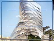
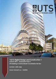
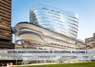
UTS currently have in place a “UTS City Campus Master Plan”. This Master Plan consists of<br />
the upgrade of the previously occupied Building 2. Building 2, at its time of operation, was<br />
mainly used as a space for students to study, access printing facilities, and attend class in<br />
lecture rooms.<br />
Building 2, nestled between Building 11 and the Tower on Broadway<br />
BUILDING TYPE AND PURPOSE<br />
Building 2 will ultimately be classified as a Commercial Building which will be used to<br />
service the ever growing number of students enrolling into UTS. The new development will<br />
comprise of 16 levels, which includes two floors underground. The final plan for the use of<br />
the building is not yet confirmed but the current proposal includes a range of various student<br />
spaces, the new UTS library in the lower levels and the upper levels to be dedicated to high<br />
end research facilities for students to utilise.<br />
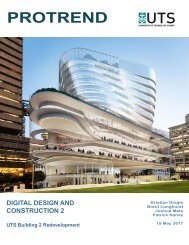
Artist's impression of the transformed Building 2<br />
16470 - Digital Design and Construction 2<br />
3
SCOPE AND CONSTRUCTION METHODS<br />
The original scope for the project was to partially demolish Building 2 and maintain areas<br />
which would have been treated as a foundation to the newly proposed Building 2. As the<br />
construction works commenced, the idea was raised and proposed to have the building<br />
demolished in its entirety and commence with a new build from the ground up, this idea was<br />
then agreed upon by the project stakeholders. The reason for this change in methodologies<br />
was that the project delivery team could produce a high end product. This was also<br />
supplemented with the difficulties surrounding the interface between the old and proposed<br />
building, in particular, the services.<br />
The overall construction delivery will be heavily guided by the implementation of 4D<br />
technologies which include Revit and Navisworks. The construction delivery team, RCC, will<br />
incorporate the use of 4D technology not only amongst themselves and consultants, but will<br />
also ensure the subcontractors<br />
16470 - Digital Design and Construction 2<br />
4
2. DESCRIPTION OF MODEL PROFILES<br />
ARCHITECHTURAL AND FAÇADE - Khanh Duc Trinh<br />
Regarding the architectural elements of the Building 2 – UTS Central, FJMT in collaboration with<br />
DJRD and Lacoste + Stevenson did an amazing job to convey its unique design in the architecture file<br />
provided. The elements were broken down into levels and separated into Architecture and Façade<br />
folders. The components that make up the elements is curtain walls, ceiling, doors, floor finishes and<br />
internal walls. They are then broken down to specific levels by using the find item tool to generate<br />
search sets. This was only made possible due to the fact that the overall design of the project was well<br />
put together with very detailed profile description.<br />
IDENTIFICATION OF DISCREPANCIES IN DISCIPLINE-SPECIFIC MODELS<br />
As mentioned above, the architecture model was very put together and made it fairly straight forward<br />
to generate search sets. There were a few discrepancies that have it difficult to produce search sets for<br />
some component such as ceiling, furniture, door and stairs. The main issue was different components<br />
of the model had similar or exact properties with no allocated levels to differentiate. Please see<br />
screenshots below for example.<br />
1. Ceiling components were not able to be identified in specific levels. The solution was to<br />
tediously enter in property names and provide “or” condition to link to other ceiling panels on<br />
the same level. Please screen-shot below for a visual explanation<br />
16470 - Digital Design and Construction 2<br />
5
2. Some searches set were difficult to obtain due to the fact that there was lack of description or<br />
similar profile description. For example, when using property names to distinguish the<br />
specific levels of each ceiling, some components in the façade would be included as well.<br />
Please see as per screen-shot below.<br />
3. It was extremely difficult to separate furniture and joinery items into level search sets, as they<br />
all had exact properties. Please see below screen-shot<br />
16470 - Digital Design and Construction 2<br />
6
4. Lift door housing/frames were included in the door search set due to how similar the<br />
properties were. However the main problem was the clash of the lift panel against the<br />
structural block wall. Please see below screen-shot<br />
5. Below level 8, the model does not prescribe as description or layer profile to the properties,<br />
therefore making it near impossible to allocated search sets. Example of this are the<br />
escalators, spinal stairs and bulkheads.<br />
16470 - Digital Design and Construction 2<br />
7
STRUCTURAL - Mohamad Mariam<br />
Structural discipline comprises of the building foundations, these include all vertical and horizontal<br />
elements:<br />
<br />
<br />
<br />
<br />
<br />
<br />
<br />
<br />
<br />
Design and physical integrity<br />
Footings<br />
Piles<br />
Columns<br />
Core (load bearing) walls<br />
Beams (transfer of horizontal loads)<br />
Slabs<br />
Concrete upturn, downturn, HOB‟s, Set downs Pits and Vertical and Horizontal Penetrations.<br />
All concrete, reinforcement steel and supporting structural elements.<br />
Structural component is the prerequisite for all other Construction Disciplines. It integrates into its<br />
engineering specification all live and dead loads including the integration of all architectural and<br />
façade elements.<br />
16470 - Digital Design and Construction 2<br />
8
IDENTIFICATION OF DISCREPANCIES IN DISCIPLINE-SPECIFIC MODELS<br />
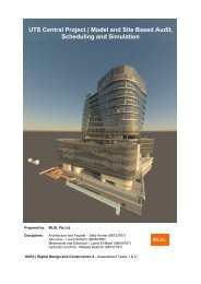
We have been provided with an incomplete 4D Modelling Design of the UTS-BUILDING 2,<br />
CENTRAL PROJECT. The model comprises of all the disciplines into one file. The structure of the<br />
above project is not your typical design that incorporates 90 degree vertical elements and cornered<br />
edges that are plumbed to the above and below floors.<br />
It is crucial that the structural discipline is well detailed with regards to item selection and<br />
incorporated correct and detailed contract programme.<br />
When we commenced working on the Search Sets it was quickly visible that the search sets and<br />
programme lacked in a great deal of information. When collaborating both Search Sets and<br />
Construction Programme we picked up some discrepancies.<br />
Discrepancies include:<br />
1. The program and Search sets had generically separated the beams and slabs. In traditional<br />
construction of Floors the beams and slabs are simultaneously constructed as they are paired<br />
with one another.<br />
To rectify this issue we have added an “or condition” to the search sets which includes the beams into<br />
the slabs component.<br />
16470 - Digital Design and Construction 2<br />
9
Find items Window that indicates the „Or Condition‟:<br />
When integrating the 2 search sets we had to integrate it into the RCC Construction program. This<br />
will assist into creating a more realistic assumption of the construction methodology.<br />
2. Discrepancy was identified when creating a search set for the core and the stair of the<br />
building (Level 8 – Roof). The Core did not integrate the stair subsequently. To rectify the<br />
issue we integrated the Stair Search Sets into a different Programme action.<br />
16470 - Digital Design and Construction 2<br />
10
3. The program had another design affiliated discrepancy on Level 18. Where it was clearly<br />
visual that there had been no stairs design onto level 18 leading from Level 17.<br />
16470 - Digital Design and Construction 2<br />
11
4. Originally the search sets and Construction Program had separated the Universal beam<br />
columns level 17 into two separated installation sequence. This in fact create addition<br />
construction time to the program.<br />
5. While creating the time liner sequence with integration of the construction programme. The<br />
simulation showed the core of the building leading the slabs and beams in construction by up<br />
to 3 Floors. This id due to the use of a Jump Form. The discrepancy is located in the Design<br />
where the cores included an Upturn as part of the IFCWALLS. In actuality it will not be a<br />
realistic approach in construction.<br />
16470 - Digital Design and Construction 2<br />
12
6. When rectifying the Search Sets it was very difficult to remove the condition as there where<br />
„Or Conditions‟ implied in above elements.<br />
To rectify the problem we had deleted above conditions of the Core Element and<br />
implemented a new item with the GUID name after making the selection we used the Mitigate<br />
action. This solved the issue without having to creating a Search Set.<br />
Find Items changes:<br />
16470 - Digital Design and Construction 2<br />
13
7. On level 8 Elemental break down there were concrete upturns that were not included part of<br />
the slab Search Sets. To rectify the issue we had created an „Or Condition‟ part of the “FRP<br />
Beams and Slab P2_8”. This had shortened the Construction Program and added a realistic<br />
approach to the Design Coordination.<br />
Integration to Level 8 Pour 2 sequence as an „Or Condition‟.<br />
16470 - Digital Design and Construction 2<br />
14
MECHANICAL – Nicholas Zambounis<br />
The mechanical model is predominately comprised of the following three items:<br />
1. Exhaust Air<br />
2. Return Air<br />
3. Supply Air<br />
IDENTIFICATION OF DISCREPANCIES IN DISCIPLINE-SPECIFIC MODELS<br />
Throughout the mechanical model, there has been no separation between vertical and horizontal<br />
elements, therefore when searching for either of the three abovementioned items on any particular<br />
level, both horizontal and vertical elements are populated.<br />
There have been a considerable amount of discrepancies identified within the Mechanical model<br />
which include:<br />
1. Ductwork is not able to be identified until insulation is hidden as per the below screen-shot:<br />
16470 - Digital Design and Construction 2<br />
15
2. Vertical ducts for Exhaust air located on Level 8 extend through the building as per the below<br />
screen-shot:<br />
3. Vertical Mechanical Pipes located on Level 8 extend through the building as per the below<br />
screen-shot:<br />
16470 - Digital Design and Construction 2<br />
16
4. Exhaust Air located on Level 9 extends through the building as per the below screen-shot:<br />
5. Exhaust Air located on Level 10 extends through the building as per the below screen-shot:<br />
16470 - Digital Design and Construction 2<br />
17
6. When searching for Exhaust Air on Level 11, a mechanical component is also found on Level<br />
12 as per the below screen-shot:<br />
7. When searching for Exhaust Air on Level 12, a mechanical component is also found on Level<br />
13 as per the below screen-shot:<br />
16470 - Digital Design and Construction 2<br />
18
8. When searching for Exhaust Air on Level 13, vertical ductwork extends through the building<br />
as per the below screen-shot:<br />
9. When searching for Exhaust Air on Level 14, vertical ductwork extends through the building<br />
as per the below screen-shot:<br />
16470 - Digital Design and Construction 2<br />
19
10. When searching for Exhaust Air associated with Level 15, Mechanical components on Level<br />
16 are shown, as per the below screen-shot:<br />
11. When searching for Exhaust Air associated with Level 17, vertical duct throughout the<br />
building appears as per the below screen-shot:<br />
16470 - Digital Design and Construction 2<br />
20
12. When searching for Supply Air associated with Level 17, vertical ductwork throughout the<br />
building appears as per the below screen-shot:<br />
13. When searching for Exhaust associated with the Roof Level, ductwork which extends through<br />
the building appears as per the below screen-shot:<br />
16470 - Digital Design and Construction 2<br />
21
ELECTRICAL – Nicholas Zambounis<br />
The Electrical model predominately comprises of the following four items:<br />
1. Cable trays<br />
2. Security boards<br />
3. Distribution boards<br />
4. Communications data boards<br />
IDENTIFICATION OF DISCREPANCIES IN DISCIPLINE-SPECIFIC MODELS<br />
There have been a considerable amount of discrepancies identified within the Electrical model which<br />
include:<br />
1. When searching for Cable Trays associated with Level 8, a vertical cable tray which extends<br />
through the building is found, as per the below excerpt:<br />
2. When searching for Cable Trays associated with Level 11, vertical cable trays on lower levels<br />
are found, as per the below excerpt:<br />
16470 - Digital Design and Construction 2<br />
22
3. Generally, when searching for cable trays, there is no separation between horizontal and<br />
vertical trays as per the below excerpt:<br />
16470 - Digital Design and Construction 2<br />
23
PLUMBING – Selver Moshe<br />
The plumbing components of the model include the following items –<br />
1. Hydraulic drainage services which is further broken down in horizontal and vertical elements<br />
2. Hydraulic pressure services<br />
IDENTIFICATION OF DISCREPANCIES IN DISCIPLINE-SPECIFIC MODELS<br />
HYDRAULIC DRAINAGE SERVICES<br />
1. Generally, when searching for drainage pipes, there is no separation between horizontal and<br />
vertical pipes, as per the below excerpt:<br />
16470 - Digital Design and Construction 2<br />
24
2. When searching for Hydraulic Horizontal Drainage pipes associated with Level 8, drainage<br />
pipes which extended vertically through the building as found, as per the below excerpt:<br />
3. When searching for pipes associated with Level 10, pipes from above levels are shown, as per<br />
the below excerpt:<br />
16470 - Digital Design and Construction 2<br />
25
4. When searching for pipes associated with Level 17, pipes which extend through the building<br />
are found, as per the below excerpt:<br />
HYDRAULIC PRESSURE SERVICES<br />
1. When searching for Hydraulic Pressure Services associated with Level 8, a vertical Hydraulic<br />
Pressure Pipe which extends through the building is found as per the below excerpt:<br />
16470 - Digital Design and Construction 2<br />
26
FIRE – Selver Moshe<br />
The fire model consists of the following building elements –<br />
1. Fire cable trays<br />
2. Fire pipes<br />
3. Fire sprinklers<br />
IDENTIFICATION OF DISCREPANCIES IN DISCIPLINE-SPECIFIC MODELS<br />
1. Generally, when searching for Fire Pipes there is no separation between vertical and<br />
horizontal elements, as per the below excerpt:<br />
16470 - Digital Design and Construction 2<br />
27
2. When searching for Fire Cable Trays associated with Level 8, vertical Fire Cable Trays which<br />
extend through the building are found, as per the below excerpt:<br />
3. When searching for Fire Pipes associated with Level 17, a vertical Fire Pipe which extends<br />
through the building is found, as per the below excerpt:<br />
16470 - Digital Design and Construction 2<br />
28
3. DESCRIPTION OF SITE AND CLIENT PROFILE<br />
LOCATION AND BOUNDARY<br />
PROJECT NAME: Building 2- UTS Central<br />
PROJECT ADDRESS: 16/1 Broadway, Ultimo NSW 2007<br />
The project is located on Broadway (corner of Jones St and Broadway) that will be broken down into<br />
phases, first phase which will be the redevelopment of building 2 which will include Learning<br />
Commons and research space. The works on phase one commenced in November 2016 where<br />
demolition took place to the existing building 2.<br />
The second phase of the project comprises of an extension to the Tower Building one. The extensions<br />
include having podium to the main entrance and an informal public learning space.<br />
Prior to the commencement of construction Broadway and Jones St had open access ways to one<br />
another. Due to the commencement of the project and the need for hoardings for the safety and<br />
clearance of the public. They have closed the corner access between the two roads.<br />
The front of Building 2 (encapsulated by distinctive Glass Podium from Levels 3-7) is<br />
located to the Southern side to Broadway and to the North of the building it faces the Alumni<br />
Green Building.<br />
16470 - Digital Design and Construction 2<br />
29
Building 2 is in the centre of Broadway. It is:<br />
<br />
<br />
<br />
5 minute walk from central station<br />
Across the road from Central Park.<br />
Ultimo Tafe NSW<br />
Due to the limited working/construction space it had originally limited RCC with material<br />
storage and equipment mobility. For this reason RCC and the Sydney Council have agreed to<br />
go forward in extending the Site Boundary across Jones St. As a result there will be no access<br />
between Broadway and Jones St via car.<br />
The Eastern Boundary is adjacent to the Tower Building 1, where it has closed the eagres and<br />
access between the two buildings.<br />
16470 - Digital Design and Construction 2<br />
30
VEHICULAR TRAFFIC AND PEDESTRIAN FLOWS<br />
PEDESTRIAN<br />
Due to the restricted location of the site, it is a very crucial stage of managing the flow of vehicle and<br />
pedestrian flow as it is a very highly condensed zone. The location is known to have a large number<br />
of pedestrian that are mixed between UTS Students/Staff, construction staff and the General Public.<br />
In the year 2014, the statistics illustrate that over 39,000 students are enrolled in UTS with 27,000<br />
being full time students. This number is since to be greater and will continue to expand over the<br />
coming year.<br />
„NEW‟ Website published on 15/09/2017 that Central Station has an estimated number of 270,000<br />
individuals pass through it on a daily basis.<br />
Hours of working will be restricted 7am to 5pm Monday to Friday. There will be no work on<br />
Saturday. Any additional out of hours work must be granted by Sydney City Permission and<br />
additional costs with full disclosure in the reporting documentation.<br />
TRAFFIC<br />
RCC have arranged site vehicle access to be through the Jones St. this will limit the flow of<br />
traffic in the region. The only route into Jones St will be via the entry of wattle St and exiting<br />
through Thomas St to Harris St.<br />
There has been traffic controllers located at the gate of the project on Jones St that direct all<br />
pedestrian activity and flow when there are equipment, vehicles and machinery exiting and<br />
entering the project.<br />
16470 - Digital Design and Construction 2<br />
31
OTHER SITE SPECIFIC & LOGISTICS DETAILS<br />
Surrounding university building premises must be completely operational, occupied and no<br />
disturbance must be made to the Occupants and any distractions must be prevented or at a bare<br />
minimum.<br />
All users to the surrounding buildings must have a safe, free of any issues/costs and uninterrupted<br />
from their activities and duties.<br />
Access to existing university buildings in use will need to be programmed with at least seven (7)<br />
days‟ and a notice must be submitted to the users and clients before any changes or plans can proceed.<br />
Strict observance to all safety necessities must be practical with all the works to be carried out to<br />
Controlling Consultants‟ requests.<br />
It is vital, regardless of main site conditions, that existing structures be protected from all-weather<br />
elements during the course of these works, particularly water entrance.<br />
SITE DELIVERIES<br />
Due to the site location and site boundaries, site deliveries where a challenge in the early stages. the<br />
Entry of the site on Jones St, must be will managed and adhered to at all times as the General Public<br />
and UTS students use it as a walk way to cross between Buildings 10 and Alumni Green.<br />
By having the logistics delivered to site via Jones St was strategically arranged as the vehicle flow of<br />
the general public is much lower than that of Broadway. This plan eases the risk of pedestrian clashes<br />
and any harm.<br />
This also reduces the amount of expected delays in traffic on Broadway and as a result will not disrupt<br />
the flow.<br />
16470 - Digital Design and Construction 2<br />
32
CLIENT OPERATIONS AND CONSTRAINTS<br />
Due to the nature of the project, it is located in an educational facility. Restriction they had come<br />
across include; that the surrounding university building premises are fully occupied and disruption to<br />
the occupants must be kept to a minimum.<br />
This is challenging for RCC and all contract work that are taking place. As a result of this action UTS<br />
had agreed to delay the demolition phase from mid-year 2016 to the University Summer Holidays.<br />
Additional all safe, free and any uninterrupted access to building 2 must be maintained for all<br />
occupants and the general public.<br />
This condition increases the risk and responsibility of RCC to maintain a structured method of<br />
manoeuvrability in and out of the site. This is a priority as it increases RCC liability.<br />
Access to existing university buildings in use will need to be programmed with at least seven days‟<br />
notice in advance given to the occupants. This conditions puts pressure on RCC to continually follow<br />
up on the program and take into consideration any delays that occur on the critical path.<br />
It is crucial that there is strict focus on all safety requirements to all personnel working within that<br />
facility and carried out in accordance to Regulatory Authorities requirements.<br />
An additional condition to the responsibility of RCC is that it is vital regardless of fundamental site<br />
conditions that all existing structures are to be protected from all-weather elements during the time<br />
undertaken to construct this project. With special focus on water access.<br />
This is additional costings for RCC from the aspect of labour, materials and the liability of having to<br />
secure the existing building whilst constructing a complex project.<br />
16470 - Digital Design and Construction 2<br />
33
4. RISK ANALYSIS AND MANAGEMENT APPROACH<br />
With a project of this size and in a busy location, there are many potential risks for the builder. <strong>MSND</strong><br />
has drawn on their experiences of past project in similar environment to highlight the risks involve<br />
with a project like this. The environment that this building is located in subjects it to unique hazards<br />
that would likely not be for other projects<br />
CONTROLLED RISK<br />
Location<br />
Traffic Management The site of UTS building 2 is surrounded by major road such as Broadway<br />
road, which links the inner west and south west suburbs to the city.<br />
Therefore the peak hour around the southern side of the building is a major<br />
risk to the project as it causes difficulties scheduling deliveries. It is also to<br />
be noted that ideas of temporarily closing this road is not an option as it<br />
would cause chaotic delays to the traffic network. Permits from the council<br />
and certified traffic controllers will need to be employed to help mitigate<br />
the hindrance to the traffic if it is not possible to use the back streets.<br />
Thomas street and Jones street are located on the western side of the<br />
building and due to their nature of being small in size, the risk of<br />
transporting a large load could potential cause road damages and incur<br />
council fines. It is noted that Richard Crookes Construction has hired and<br />
blocked off Jones street to serve as a loading dock and site accommodation.<br />
This was a great idea however would incur substantial costs. We<br />
recommend to execute large unloading/loading of deliveries during the<br />
Pedestrian<br />
Management<br />
Material and labour<br />
availability<br />
night to minimise the impact to the traffic network.<br />
On top of the dense traffic surrounding the building, there is also an active<br />
university next door, therefore the risk involve with pedestrian grow even<br />
higher. With thousands of people passing the building on the daily basis,<br />
there is a major risk of pedestrian being injured along the perimeter of the<br />
project due to fallen objects. Class B hoardings and line marking to assist<br />
travellers is essential to prevent risk of injury. In addition, we will also<br />
provide traffic controllers during peak hours such as the morning rush.<br />
As discussed in traffic management, there is high risk involved with getting<br />
material delivered to site, but in addition, the site does not allow for much<br />
area to store these materials. So the risk of material management grows<br />
greatly as procuring materials would be difficult because of already logistic<br />
pressure but minimal areas to work with. This would eventually cause<br />
stress in the project programme and would incur costs and delays. The only<br />
resolution to carefully schedule materials to come as the work needs them<br />
to so they can be directly be used, instead of being stored.<br />
Being close to central Sydney, one would think that there should not be any<br />
issues with labour availability. However in the same way as material, travel<br />
time and minimal parking could potentially discourage labour resources<br />
from coming. It might incur an additional fee to convince additional<br />
resource on site or set dates of incentives such as site barbeques to<br />
encourage morale.<br />
Nosie and Vibration<br />
management<br />
As mentioned above, the project is neighbouring busy roads, shopping<br />
centre and a university, so there is a higher risk of noise and vibration<br />
causing damage to other infrastructure and residents The issue of noise and<br />
vibration is minimise through the use of class b hoardings and also noted<br />
16470 - Digital Design and Construction 2<br />
34
Air quality<br />
Management<br />
Project Type<br />
Contract variations<br />
Client operations and<br />
Constraints<br />
Safety<br />
Standards and<br />
Legislations<br />
that Richard Crookes utilise the university holiday to bulk excavated the<br />
site. But also conducting geotechnical reports and inspections are a must<br />
when minimising these risks.<br />
One of the main risk with conducting demolition and excavation is air<br />
quality management. Much needed planning is required to reduce this<br />
problem. Measures to reduce this risk could be conducting environmental<br />
control maps, retaining as much vegetation where possible, scheduling<br />
construction activities that may generate dust in accordance with wind<br />
conditions, covering expose surfaces and damping down the active areas by<br />
using watering mechanisms.<br />
Being a Design and Construct project, most of the risk lies with the<br />
contractor. It involves risks such as losses of time and money due to delays<br />
of information and disputes of execution of work and delays in payment.<br />
But one of the stand outs are contract variations, which would be certain<br />
with this project like this. It is noted that a redesign of the entire project<br />
was done in the demolition and excavation period of the project. When<br />
constructing to unapproved designs, it is certain that variations will occur<br />
and potentially causes a blow out of the budget. <strong>MSND</strong> will be actively<br />
integrating its project team with the design team to minimise loss of time<br />
due to lack of information.<br />
The university of technology is the client and its operations and constraint<br />
will cause problems in the success of this project. Risks such as having to<br />
adhere to student seasonal timetables may delay construction due to<br />
scheduling around examination and study periods. Another risk is the<br />
university having their own codes and protocols which could also delay<br />
construction time by putting pressure on the administration side of the<br />
work. There is no solution to such a unique risk, it is only recommended<br />
that careful planning and management is used throughout the life of the<br />
project.<br />
In this day and age, safety is considered as the most important subject with<br />
conducting any work. Management plans, SWMS, constant inspection and<br />
inductions is the key to preventing any unsafe work on site. However,<br />
<strong>MSND</strong> understands that if an incident was to occur, we will take the<br />
necessary steps and procedures to ensure a professional respond is<br />
delivered.<br />
Getting standards and legislation wrong will cause major costs and delay to<br />
the project and therefore during the design phrase, <strong>MSND</strong> will ensure the<br />
project will meet all standards and legislation involved. However, in a rare<br />
case where it has not meet the suitable outcome, <strong>MSND</strong> will draw on its<br />
experience to resolve the problem in a case by case basis.<br />
Time-based<br />
Programme<br />
Calendar Events<br />
Delays to the programme will evidently cause costs but with careful<br />
management and scheduling, this risk should not be an issue. Extension of<br />
time are used with unforseen circumstance occur and consider with proper<br />
reasoning.<br />
Being so central around university and the city, planning and schedule will<br />
be needed to consider the university timetable and holidays to ensure there<br />
are less clashes with its occupants. This is done by conducting less<br />
destructive work during the day and more damaging work on the weekend<br />
and holidays<br />
16470 - Digital Design and Construction 2<br />
35
UNCONTROLLED RISKS<br />
Weather<br />
An unpredictable risk that may occur are long delays due to bad weather<br />
and damaging condition which will cause delays to the programme. As<br />
mentioned before, extension of time and delay costs will be considered and<br />
submitted with rational reasons. But this is to be dealt with in a case by<br />
case manner.<br />
Industrial Action Industrial actions could strike in a sudden manner and would cause major<br />
delays to the project. As like above, extension of time and delay costs will<br />
be considered and submitted with rational reasons, but this is to be dealt<br />
with in a case by case manner. <strong>MSND</strong> will work closely with unions to<br />
take the necessary action to overcome this risk.<br />
16470 - Digital Design and Construction 2<br />
36
5. PROPOSED SITE LAYOUT<br />
SITE MANAGEMENT APPROACH<br />
1. SITE PERIMETER FENCING, HOARDINGS<br />
The entire site boundary will be enclosed by Class A hoarding which will be painted black<br />
and wrapped with approved City of Sydney Council banners to minimise vandalism and<br />
increase streetscape appearance during construction. The perimeter fencing will be securely<br />
locked at all times to ensure there is no access from the public to maintain safety. Further to<br />
this, RCC will provide B Class, overhead structural protective hoarding along the Broadway<br />
boundary to protect pedestrians walking past the site from any potential falling objects.<br />
2. CRANE-AGE‟ STRATEGY<br />
The site will be serviced with the use and implementation of a luffing crane. This crane will<br />
be situated on the northern boundary closest to Alumni Green and will have the ability to<br />
service the entire site. The luffing crane to be used will be the J80 PA from the Titan Cranes<br />
luffing crane range which has a 40 metre jib radius. This crane has the capacity to lift 1300kg<br />
at the tip. This will be sufficient to service the job as required.<br />
16470 - Digital Design and Construction 2<br />
37
3. SITE DELIVERIES<br />
All site deliveries will come through the Jones Street entrance as we will have a double swing<br />
gate incorporated into the A Class hoarding. These trucks will then mobilise in the material<br />
storage area for unloading. All deliveries will need to be booked 24 hours in advance with the<br />
site team to ensure the process is managed in an efficient manner. The site deliveries will be<br />
managed with two traffic controllers who will be located on Jones Street full time to direct<br />
trucks in and out of the site.<br />
4. MATERIALS HANDLING<br />
There will be four critical plant items which will service this project, which include:<br />
a. Manatou (Telehandler) – The manatou will be used to fork unload pallets and<br />
other large deliveries straight off the back of trucks and utes. The manatou has<br />
the ability the drive up and down Jones St (within the confines of the site) and<br />
therefore provides materials handling with great flexibility.<br />
The telehandler also has the ability to move skip bins to any level location on<br />
the site, which will increase productivity by reducing waste and obstructions.<br />
b. Luffing Crane – The luffing crane will service the site by lifting materials to<br />
all levels above ground, including but not limited to:<br />
i. Reinforcement<br />
ii. Post Tension Coils<br />
iii. Rubbish Bins<br />
iv. Formwork<br />
v. Scaffold<br />
16470 - Digital Design and Construction 2<br />
38
c. Man and Materials Hoist – The installation of a man and materials hoist is<br />
required to comply with state regulations as the building is above four stories<br />
high.<br />
The hoist will have a capacity equal to 2tonne, and internal car dimensions of<br />
1500mm x 3200mm in order to transport large materials to above-ground<br />
levels when the crane is being utilised by other critical building elements.<br />
d. Retractable Loading Platforms – Platforms will be installed at every working<br />
level and will be utilised to load materials to floors which are enclosed by the<br />
level above. Once materials land on platforms, pallets jacks will be used to<br />
transport materials from the landing platforms to relevant areas.<br />
16470 - Digital Design and Construction 2<br />
39
5. SITE ACCOMMODATION<br />
RCC will provide 2 sets of 4 double stacked Royal Wolf Sheds (6x3m), which in total will<br />
provide 16 sheds. These sheds will be set up to ensure all workers on site have designated<br />
areas to have their breaks. The large number of sheds will comply with WHS requirements to<br />
ensure enough space is provided to service the site at the peak of the project when we expect<br />
to have over 150 workers.<br />
6. DA APPROVED HOURS OF WORK<br />
The Development Application hours of work as approved are as follows –<br />
Monday – Friday – 7am – 6pm<br />
Saturday – 7:30am – 3:30pm<br />
These hours will be strictly adhered to by the entire project team including all subcontractors. If any<br />
works are to be carried out outside of these work hours, RCC will apply to Council for an out of hours<br />
work permit.<br />
16470 - Digital Design and Construction 2<br />
40
LAYOUT DIAGRAMS<br />
The layout diagrams below, in essence, portray the way in which the site will be established.<br />
These diagrams will allow all stakeholders, but more importantly, the project delivery team<br />
including subcontractors understand how the site will operate and function on a day to day<br />
basis.<br />
The layout diagrams include information on the items listed below –<br />
1. Site perimeter fencing and hoardings (refer to diagram 1)<br />
2. Hoardings and overhead protection (refer to diagram 2)<br />
3. Luffing crane and jib radius (refer to diagram 4)<br />
4. Site accommodation and site office (refer to diagram 1)<br />
5. Rubbish and Material Storage (refer to diagram 1)<br />
6. Material Hoists (refer to diagram 5)<br />
7. Site Access (refer to diagram 3)<br />
LAYOUT DIAGRAM 1<br />
16470 - Digital Design and Construction 2<br />
41
LAYOUT DIAGRAM 2<br />
LAYOUT DIAGRAM 3<br />
16470 - Digital Design and Construction 2<br />
42
LAYOUT DIAGRAM 4<br />
LAYOUT DIAGRAM 5<br />
16470 - Digital Design and Construction 2<br />
43
6. ANALYSIS AND IMPLEMENTATION OF RCC<br />
CONTRACT PROGRAMME<br />
ARCHITECHTURAL - Khanh Duc Trinh<br />
DEFICIENCIES IN RCC PROGRAMME AND PRESCRIBED AND ADDITIONAL SEARCH<br />
SETS IMPLEMENTED<br />
For the Architectural and Façade, the RCC contract programme included the following tasks –<br />
1. Install façade<br />
2. Internal walls<br />
3. Hang doors<br />
4. Hang ceilings<br />
5. Install floor finishes<br />
By using search set rules, we were able to differentiate and further breakdown the façade and floor<br />
finishes. The properties description were detailed enough to enable us to provide the following<br />
additional tasks<br />
1. Install curtain walls<br />
2. Install glass balustrade<br />
3. Install metal cladding<br />
4. Install carpet<br />
5. Install tiles<br />
With the further breakdown of façade and floor finishes, we have generated additional search sets to<br />
produce a more detailed programme for Building 2 – UTS Central. It is noted this was not a<br />
requirement for sequencing the programme, however we believe that this enhances the visualisation<br />
of the simulation when incorporated with the Appearance Profiler Tool.<br />
16470 - Digital Design and Construction 2<br />
44
APPLICATION OF DISCIPLINE-SPECIFIC APPEARANCE PROFILES<br />
As mentioned above, implementing colour schemes will enable the viewers to distinguish between the<br />
different disciplines. However with Architectural and Façade, we have to be wary of not applying<br />
colours and levels of transparency that would not clash or is too similar in appearance to the services<br />
as this would have an opposite effect of impairing the viewer to view the necessary services. The<br />
colours and transparency levels chosen below is utilised for Architectural and Façade –<br />
Item SERVICE/DISCIPLINE COLOUR transparency Level<br />
1. Façade White 85<br />
2. Door Lavender 75<br />
3. Carpet Salmon 85<br />
4. Tiles Turquoise 85<br />
5. Glazed Walls Light Blue 75<br />
6. Gyprock Walls Rose 85<br />
7. Ceiling Olive 65<br />
Façade shown in White<br />
16470 - Digital Design and Construction 2<br />
45
Doors shown in Lavender<br />
Carpet shown in Salmon<br />
16470 - Digital Design and Construction 2<br />
46
Tiles in Turquoise<br />
Glazed Wall in Light Blue<br />
16470 - Digital Design and Construction 2<br />
47
Gyprock Walls in Rose<br />
Ceiling in Olive<br />
16470 - Digital Design and Construction 2<br />
48
ILLUSTRATION OF THE SEQUENCE OF WORK PACKAGES THROUGH NAVISWORKS<br />
16470 - Digital Design and Construction 2<br />
49
16470 - Digital Design and Construction 2<br />
50
16470 - Digital Design and Construction 2<br />
51
STRUCTURAL - Mohamad Mariam<br />
DEFICIENCIES IN RCC PROGRAMME AND PRESCRIBED AND ADDITIONAL SEARCH<br />
SETS IMPLEMENTED<br />
Within the structural discipline model, we found that there was a deficiency in the RCC program task<br />
coordination and the model task Search sets. The Search sets where very broad and not well detailed<br />
with regards to task allocation and construction sequence. Alternatively this was reflected in the RCC<br />
construction program, where there was insufficient detail to work items and the correct task<br />
allocation.<br />
Specific line items from the RCC construction program where not in sync with the search sets. This<br />
can have a negative result with the use of Navisworks simulation. In some cases we found that a task<br />
was split into two (2) Search Sets within Navisworks however there was no need to that action as it is<br />
unrealistic and will only extend the project pour dates that will lead to a stretched out Construction<br />
Completion.<br />
For instance the Beams and Slabs where in separate Search Seats, whereas in reality they will be<br />
simultaneously completed to achieve concrete strength and a more precise working methodology.<br />
To overcome this issue we have incorporated the two Search sets into one. This resulted into<br />
delivering an accurate target Construction Program.<br />
16470 - Digital Design and Construction 2<br />
52
Specific task items as the pours 1 and 2 where separated into separated tasks and the Beams and Slabs<br />
combined into one task.<br />
16470 - Digital Design and Construction 2<br />
53
Additional Tasks and Search Sets where allocated to levels 17-Roof. These where essentially created<br />
under one heading and Search Set. This provides a more detail and specific Construction<br />
Methodology.<br />
16470 - Digital Design and Construction 2<br />
54
16470 - Digital Design and Construction 2<br />
55
APPLICATION OF DISCIPLINE-SPECIFIC APPEARANCE PROFILES<br />
Appearance profiles allow for a greater clarification of the Naviceworks simulation, as it will identify<br />
various structural elements from the remaining Project Diciplines. This will improve the visualization<br />
of other services, the likes of Mechanical, Fire and Electrical services within the Structural frame of<br />
the building.<br />
We allocated solid colors to the Structural elements the likes of gray and similar tone.<br />
In addition the color profiling we added altered transparency levels to various structural elements.<br />
This will be different depending on the location of the structure and the detail within its core.<br />
16470 - Digital Design and Construction 2<br />
56
There was greater transparency to the core and slab more than the columns and stairs as there was<br />
more services interaction.<br />
16470 - Digital Design and Construction 2<br />
57
We integrated different profile appearance to the structural:<br />
<br />
<br />
<br />
<br />
<br />
Slab- P1 + P2<br />
COLUMS P1 + P2<br />
CORE<br />
STAIRS<br />
UNIVERSAL STEEL BEAMS<br />
16470 - Digital Design and Construction 2<br />
58
16470 - Digital Design and Construction 2<br />
59
ILLUSTRATION OF THE SEQUENCE OF WORK PACKAGES THROUGH<br />
NAVISWORKSThrough the use of Navisworks we can exemplify the procedure of timeliner option<br />
which allows to us create a simulation illustrating the construction sequence by implementing the use<br />
of the RCC Construction Program.<br />
It is an accurate video which illustrates the sequence and duration of the project from beginning to<br />
end.<br />
The below screen illustrate the progression of the project Structure in accordance with the dates.<br />
16470 - Digital Design and Construction 2<br />
60
16470 - Digital Design and Construction 2<br />
61
16470 - Digital Design and Construction 2<br />
62
MECHANICAL AND ELECTRICAL – Nicholas Zambounis<br />
DEFICIENCIES IN RCC PROGRAMME AND PRESCRIBED AND ADDITIONAL SEARCH<br />
SETS IMPLEMENTED<br />
Relative to the Mechanical discipline, the RCC Contract Programme did not have tasks<br />
associated with Exhaust Air or Mechanical Pipework. It is recommended that these two items<br />
are added into the programme as separate line items to ensure the correct works sequence is<br />
executed.<br />
Also, RCC included „‟Fit off Mech Ceiling Fixtures‟‟ as a line item within their programme,<br />
however mechanical ceiling fixtures are not separable items within the Navisworks model. It<br />
is therefore recommended that this item is deleted from the programme as it is useless when<br />
creating the Navisworks simulation.<br />
Relative to the Electrical discipline, the RCC Contract Programme is not deficient. The two<br />
line items in the programme, „‟Install Electrical Equipment‟‟ and „‟Install Cable Tray‟‟ are<br />
also the only two electrical elements within the Navisworks model, therefore adding<br />
additional electrical line items to the programme would not be required<br />
16470 - Digital Design and Construction 2<br />
63
APPLICATION OF DISCIPLINE-SPECIFIC APPEARANCE PROFILES<br />
Mechanical Services shown in BLUE below –<br />
16470 - Digital Design and Construction 2<br />
64
Mechanical Services shown in BLUE below –<br />
16470 - Digital Design and Construction 2<br />
65
Electrical Services shown in YELLOW below –<br />
16470 - Digital Design and Construction 2<br />
66
ILLUSTRATION OF THE SEQUENCE OF WORK PACKAGES THROUGH NAVISWORKS<br />
16470 - Digital Design and Construction 2<br />
67
16470 - Digital Design and Construction 2<br />
68
16470 - Digital Design and Construction 2<br />
69
PLUMBING AND FIRE – Selver Moshe<br />
DEFICIENCIES IN RCC PROGRAMME AND PRESCRIBED AND ADDITIONAL SEARCH<br />
SETS IMPLEMENTED<br />
For the Plumbing and Fire, the RCC contract programme included the following tasks –<br />
1. Install fire pipe<br />
2. Fit off fire services<br />
3. Hydraulic pressure services<br />
4. Hydraulic horizontal drainage services<br />
5. Hydraulic horizontal drainage<br />
Within the Navisworks model, we were able to further breakdown the fire services as we were able to<br />
generate further detail with the availability of detailed search sets. Within the fire services model, we<br />
have further elaborated with the introduction of the below tasks –<br />
1. Install fire cable trays<br />
2. Install sprinklers<br />
With the addition of these two tasks, we have increased the amount of search sets generated within the<br />
model. This level of detail is required to be added to the program to allow for the full use of the<br />
current model properties.<br />
16470 - Digital Design and Construction 2<br />
70
APPLICATION OF DISCIPLINE-SPECIFIC APPEARANCE PROFILES<br />
In order to maintain a line of delineation between the plumbing and fire models, we have<br />
implemented colour schemes through the appearance profile function within Navisworks. These<br />
colours have been allocated as per the table below.<br />
Item SERVICE/DISCIPLINE COLOUR<br />
6. Hydraulic Pressure Services (Plumbing) Green<br />
7. Horizontal and Vertical Drainage Services Green<br />
8. Fire Services Red<br />
Hydraulic Pressure Services shown in GREEN below –<br />
16470 - Digital Design and Construction 2<br />
71
Horizontal and Vertical Drainage Services shown in GREEN below –<br />
16470 - Digital Design and Construction 2<br />
72
Fire Services shown in RED below<br />
16470 - Digital Design and Construction 2<br />
73
ILLUSTRATION OF THE SEQUENCE OF WORK PACKAGES THROUGH NAVISWORKS<br />
16470 - Digital Design and Construction 2<br />
74
16470 - Digital Design and Construction 2<br />
75
16470 - Digital Design and Construction 2<br />
76