


Create successful ePaper yourself
Turn your PDF publications into a flip-book with our unique Google optimized e-Paper software.
Captain’s Briefing<br />
I will advance the thrust levers.<br />
Follow me through on the thrust levers.<br />
Monitor all instruments and warning lights on the takeoff roll<br />
and call out any discrepancies or malfunctions observed prior<br />
to V 1<br />
, and I will abort the takeoff. Stand by to arm thrust<br />
reversers on my command.<br />
Give me a visual and oral signal for the following:<br />
• 80 knots, and I will disengage nosewheel steering.<br />
• V 1<br />
, and I will move my hand from thrust to yoke.<br />
• V R<br />
, and I will rotate.<br />
In the event of engine failure at or after V 1<br />
, I will continue the<br />
takeoff roll to V R<br />
, rotate and establish V 2<br />
climb speed. I will<br />
identify the inoperative engine, and we will both verify. I will<br />
accomplish the shutdown, or have you do it on my command.<br />
I will expect you to stand by on the appropriate emergency<br />
checklist.<br />
I will give you a visual and oral signal for gear retraction and<br />
for power settings after the takeoff.<br />
Our VFR emergency procedure is to.............................<br />
Our IFR emergency procedure is to..............................<br />
Figure 15-20. Sample captain’s briefing.<br />
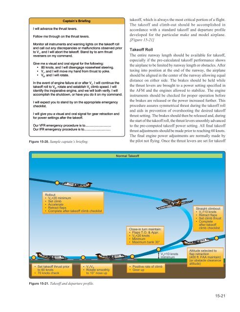
takeoff, which is always the most critical portion of a flight.<br />
The takeoff and climb-out should be accomplished in<br />
accordance with a standard takeoff and departure profile<br />
developed for the particular make and model airplane.<br />
[Figure 15-21]<br />
Takeoff Roll<br />
The entire runway length should be available for takeoff,<br />
especially if the pre-calculated takeoff performance shows<br />
the airplane to be limited by runway length or obstacles. After<br />
taxing into position at the end of the runway, the airplane<br />
should be aligned in the center of the runway allowing equal<br />
distance on either side. The brakes should be held while<br />
the thrust levers are brought to a power setting specified in<br />
the AFM and the engines allowed to stabilize. The engine<br />
instruments should be checked for proper operation before<br />
the brakes are released or the power increased further. This<br />
procedure assures symmetrical thrust during the takeoff roll<br />
and aids in prevention of overshooting the desired takeoff<br />
thrust setting. The brakes should then be released and, during<br />
the start of the takeoff roll, the thrust levers smoothly advanced<br />
to the pre-computed takeoff power setting. All final takeoff<br />
thrust adjustments should be made prior to reaching 60 knots.<br />
The final engine power adjustments are normally made by<br />
the pilot not flying. Once the thrust levers are set for takeoff<br />
Normal Takeoff<br />
Rollout:<br />
• V 2 +20 minimum<br />
• Set climb<br />
• Accelerate<br />
• Retract flaps<br />
• Complete after-takeoff climb checklist<br />
Close-in turn maintain:<br />
• Flaps T.O. & Appr.<br />
• V 2 +20 knots<br />
• Minimum<br />
• Maximum bank 30°<br />
Straight climbout:<br />
• V 2 +10 knots<br />
• Retract flaps<br />
• Set climb thrust<br />
• Complete<br />
after-takeoff<br />
climb checklist<br />
• Set takeoff thrust prior<br />
to 60 knots<br />
• 70 knots check<br />
• V 1 /V R<br />
• Rotate smoothly<br />
to 10° nose up<br />
• Positive rate of climb<br />
• Gear up<br />
V 2 +10 knots<br />
mimimum<br />
Altitude selected to<br />
flap retraction<br />
(400 ft. FAA maintain)<br />
(or obstacle clearance<br />
altitude)<br />
Figure 15-21. Takeoff and departure profile.<br />
15-21