MTR(E), MTC, MTA - Grundfos
MTR(E), MTC, MTA - Grundfos
MTR(E), MTC, MTA - Grundfos

You also want an ePaper? Increase the reach of your titles
YUMPU automatically turns print PDFs into web optimized ePapers that Google loves.
1<br />
<strong>MTR</strong>(E)<br />
20<br />
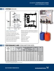
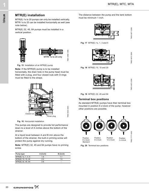
<strong>MTR</strong>(E) installation<br />
<strong>MTR</strong>(E) 1s to 20 pumps can only be installed vertically.<br />
<strong>MTR</strong>I 1s to 20 can be installed horizontally as well (see<br />
note below).<br />
<strong>MTR</strong>(E) 32, 45, 64 pumps must be installed in a<br />
vertical position.<br />
Fig. 15 Installation of an <strong>MTR</strong>(E) pump<br />
Note: If the <strong>MTR</strong>I(E) pump is to be installed<br />
horizontally, the drain hole in the pump head must be<br />
fitted with a plug, and four closed nuts with O-rings<br />
must be fitted to the straps.<br />
Closed nut<br />
Fig. 16 Horizontal installation<br />
<strong>MTR</strong>I 1s to 20 only<br />
Drain plug<br />
The pumps are designed to provide full performance<br />
down to a level of A inches above the bottom of the<br />
strainer.<br />
At a liquid level between A and B mm above the<br />
bottom of the strainer, the built-in priming screw will<br />
protect the pump against dry running.<br />
Note: <strong>MTR</strong>(E) 32, 45 and 64 pumps have no priming<br />
screw.<br />
Pump type A [inch] B [inch]<br />
<strong>MTR</strong>(E) 1s, 1, 3, 5 1.6 1.1<br />
<strong>MTR</strong>(E) 10, 15, 20 2.0 1.0<br />
<strong>MTR</strong>(E) 32, 45, 64 2.8 -<br />
TM01 4990 1399<br />
TM02 8043 4503<br />
<strong>MTR</strong>(E), <strong>MTC</strong>, <strong>MTA</strong><br />
The distance between the pump and the tank bottom<br />
must be minimum 1 inch.<br />
Fig. 17 <strong>MTR</strong>(E) 1s, 1, 3 and 5<br />
Fig. 18 <strong>MTR</strong>(E) 10, 15 and 20<br />
Fig. 19 <strong>MTR</strong>(E) 32, 45 and 64<br />
Terminal box positions<br />
As standard <strong>MTR</strong>(E) pumps have their terminal box<br />
mounted in position 6 o’clock of the pump; however<br />
other positions are possible.<br />
Position<br />
6 o’clock<br />
Standard<br />
Position<br />
9 o’clock<br />
Fig. 20 Terminal box positions<br />
B A<br />
1.0"<br />
B A<br />
1.0"<br />
1.0"<br />
A<br />
Position<br />
12 o’clock<br />
Position<br />
3 o’clock<br />
TM03 4871 3206<br />
TM03 4872 3206<br />
TM03 4873 3206<br />
TM02 7777 4003