Compact Linear Actuator with Ball Screw Drive - Schaeffler Group
Compact Linear Actuator with Ball Screw Drive - Schaeffler Group
Compact Linear Actuator with Ball Screw Drive - Schaeffler Group

You also want an ePaper? Increase the reach of your titles
YUMPU automatically turns print PDFs into web optimized ePapers that Google loves.
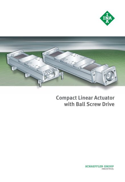
<strong>Compact</strong> <strong>Linear</strong> <strong>Actuator</strong><br />
<strong>with</strong> <strong>Ball</strong> <strong>Screw</strong> <strong>Drive</strong>
High load capacity, rigid,<br />
cost-effective, precise<br />
Foreword<br />
In many applications (for example in the handling and automation<br />
sector), small loads must be moved reliably, quickly and accurately.<br />
Furthermore, there is often very little space available to<br />
accommodate handling systems.<br />
For these applications, we have developed our new compact linear<br />
actuators of series MKUVS32.<br />
The new compact linear actuators are standard, ready-to-fit compact<br />
actuators <strong>with</strong> high rigidity and load carrying capacity.<br />
They can support forces from all directions (apart from the direction<br />
of motion) and moments about all axes.<br />
They contain a precise guidance system, a rigid support rail and a<br />
precise drive unit <strong>with</strong> a high precision spindle.<br />
Accessories The comprehensive standard range can be further optimised by<br />
means of a range of accessories precisely matched to various<br />
application requirements.
2 TPI 181 <strong>Schaeffler</strong> <strong>Group</strong> Industrial
<strong>Compact</strong> linear actuator<br />
<strong>with</strong> ball screw drive<br />
Page<br />
Product overview <strong>Compact</strong> linear actuator <strong>with</strong> ball screw drive ............................ 4<br />
Features Applications ............................................................................. 6<br />
Sealing..................................................................................... 6<br />
Support rail .............................................................................. 7<br />
Carriage.................................................................................... 7<br />
<strong>Ball</strong> screw drive ........................................................................ 8<br />
Available designs ..................................................................... 9<br />
Design code.............................................................................. 10<br />
Design and<br />
safety guidelines<br />
Maximum travel speed of carriage............................................. 11<br />
Lubrication ............................................................................... 12<br />
Location of support rail ............................................................. 14<br />
Stroke length ............................................................................ 16<br />
Accuracy Support rail .............................................................................. 18<br />
Accessories Sensors .................................................................................... 19<br />
Coupling housing cover............................................................. 20<br />
Motor adapter plates ................................................................ 21<br />
Couplings ................................................................................. 21<br />
Clamping lugs........................................................................... 22<br />
Ordering example,<br />
ordering designation<br />
................................................................................................ 23<br />
Dimension tables <strong>Compact</strong> linear actuators <strong>with</strong> ball screw drive<br />
<strong>Compact</strong> linear actuator <strong>with</strong> one carriage,<br />
<strong>with</strong>out strip cover ...............................................................<br />
<strong>Compact</strong> linear actuator <strong>with</strong> one carriage,<br />
24<br />
<strong>with</strong> strip cover ....................................................................<br />
<strong>Compact</strong> linear actuator <strong>with</strong> two carriages,<br />
26<br />
<strong>with</strong>out strip cover ...............................................................<br />
<strong>Compact</strong> linear actuator <strong>with</strong> two carriages,<br />
28<br />
<strong>with</strong> strip cover ....................................................................<br />
Accessories<br />
30<br />
Worm couplings ................................................................... 32<br />
Cross couplings.................................................................... 33<br />
Motor adapter plates............................................................ 34<br />
<strong>Schaeffler</strong> <strong>Group</strong> Industrial TPI 181 3
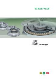
Product overview <strong>Compact</strong> linear actuator<br />
<strong>with</strong> ball screw drive<br />
<strong>Compact</strong> linear actuators MKUVS32<br />
4 TPI 181 <strong>Schaeffler</strong> <strong>Group</strong> Industrial<br />
00014831
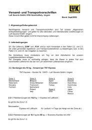
Accessories<br />
Motor adapter plate<br />
Coupling<br />
Coupling housing cover<br />
APL<br />
Sensors INI<br />
Clamping lug SPPR<br />
KUP ADH<br />
<strong>Schaeffler</strong> <strong>Group</strong> Industrial TPI 181 5<br />
000148F5<br />
00014A81<br />
000148F7<br />
000148F8<br />
000148F6
<strong>Compact</strong> linear actuator<br />
<strong>with</strong> ball screw drive<br />
Features <strong>Compact</strong> linear actuators MKUVS32 comprise a support rail,<br />
one or two carriages guided in the support rail and a high precision<br />
ball screw drive.<br />
The carriage is guided in the support rail by means of two or four<br />
linear recirculating ball bearing units KUVS32.<br />
Due to their wide base and small height, the linear actuators of<br />
the SLIVER series allow high performance <strong>with</strong>in compact<br />
dimensions.<br />
These linear actuators allow accelerations of up to 30 m/s 2<br />
and travel speeds of up to 1 m/s.<br />
The maximum stroke length is 1022 mm.<br />
Applications The compact linear actuators can support forces from all directions<br />
and moments about all axes. They offer high load carrying capacity<br />
<strong>with</strong> high precision.<br />
They are highly suitable for applications in:<br />
■ assembly systems, for example in semiconductor production<br />
■ inspection and measurement systems<br />
■ medical equipment<br />
■ electronic component manufacture<br />
■ handling systems<br />
■ automatic welding equipment.<br />
Sealing In order to protect the linear guidance system and drive spindle<br />
against contamination, linear actuators MKUVS32 can be supplied<br />
<strong>with</strong> strip covers made from alloy sheet steel (suffix ADA).<br />
In this design, the carriages are produced <strong>with</strong> a covering strip guide<br />
on both end faces. As a result, the stroke length is reduced.<br />
6 TPI 181 <strong>Schaeffler</strong> <strong>Group</strong> Industrial
Support rail The support rail is a composite rail, Figure 1. It comprises a profiled<br />
carrier rail made from anodised aluminium and a guideway for the<br />
linear recirculating ball bearing units. The integral slots allow simple<br />
mounting of end position and zero point sensors.<br />
The maximum length of the support rail is 1100 mm.<br />
Figure 1<br />
Support rail 00014A46<br />
Carriage The carriage consists of an anodised aluminium saddle plate,<br />
the spindle nut and two or four linear recirculating ball bearing<br />
units KUVS32, Figure 2. It is driven by means of the ball screw drive.<br />
The linear guidance system and the spindle nut can be relubricated<br />
via two lubrication nipples on each of the longitudinal faces.<br />
The carriage has an integrated magnet for Hall sensors.<br />
Figure 2<br />
Carriage 00014A45<br />
<strong>Schaeffler</strong> <strong>Group</strong> Industrial TPI 181 7
<strong>Compact</strong> linear actuator<br />
<strong>with</strong> ball screw drive<br />
Longer carriage or two carriages In order to support higher loads, linear actuators <strong>with</strong> a longer<br />
carriage are available (suffix 80).<br />
<strong>Linear</strong> actuators <strong>with</strong> carriages of the standard or long design<br />
are also available <strong>with</strong> two carriages arranged in series.<br />
The second carriage is not driven and is freely movable.<br />
Location The carriage has threaded holes for fixing to the adjacent<br />
construction.<br />
<strong>Ball</strong> screw drive The high precision ball screw drive is available <strong>with</strong> a pitch of 2 mm,<br />
4 mm, 10 mm or 20 mm.<br />
The ball screw drive has a pitch accuracy of 52 �m/300 mm and a<br />
repeat accuracy of �20 �m for L 2 � 550 mm.<br />
The maximum spindle speed is 3 000 min –1 .<br />
8 TPI 181 <strong>Schaeffler</strong> <strong>Group</strong> Industrial
Available designs Available designs: see Figure 3 and Figure 4.<br />
Figure 3<br />
Available designs,<br />
actuators <strong>with</strong> one carriage<br />
Figure 4<br />
Available designs,<br />
actuators <strong>with</strong> two carriages<br />
MKUVS32-KGT/2<br />
MKUVS32-KGT/4<br />
MKUVS32-KGT/10<br />
MKUVS32-KGT/20<br />
MKUVS32-80-KGT/2<br />
MKUVS32-80-KGT/4<br />
MKUVS32-80-KGT/10<br />
MKUVS32-80-KGT/20<br />
MKUVS32-KGT/2-ADA<br />
MKUVS32-KGT/4-ADA<br />
MKUVS32-KGT/10-ADA<br />
MKUVS32-KGT/20-ADA<br />
MKUVS32-80-KGT/2-ADA<br />
MKUVS32-80-KGT/4-ADA<br />
MKUVS32-80-KGT/10-ADA<br />
MKUVS32-80-KGT/20-ADA<br />
MKUVS32-KGT/2-W2<br />
MKUVS32-KGT/4-W2<br />
MKUVS32-KGT/10-W2<br />
MKUVS32-KGT/20-W2<br />
MKUVS32-80-KGT/2-W2<br />
MKUVS32-80-KGT/4-W2<br />
MKUVS32-80-KGT/10-W2<br />
MKUVS32-80-KGT/20-W2<br />
MKUVS32-KGT/2-ADA-W2<br />
MKUVS32-KGT/4-ADA-W2<br />
MKUVS32-KGT/10-ADA-W2<br />
MKUVS32-KGT/20-ADA-W2<br />
MKUVS32-80-KGT/2-ADA-W2<br />
MKUVS32-80-KGT/4-ADA-W2<br />
MKUVS32-80-KGT/10-ADA-W2<br />
MKUVS32-80-KGT/20-ADA-W2<br />
MKUVS32-OA<br />
MKUVS32-80-OA<br />
MKUVS32-OA-ADA<br />
MKUVS32-80-OA-ADA<br />
MKUVS32-OA-W2<br />
MKUVS32-80-OA-W2<br />
MKUVS32-OA-ADA-W2<br />
MKUVS32-80-OA-ADA-W2<br />
<strong>Schaeffler</strong> <strong>Group</strong> Industrial TPI 181 9<br />
00014858<br />
00014859
<strong>Compact</strong> linear actuator<br />
<strong>with</strong> ball screw drive<br />
Design code For the design codes of the available designs and for the<br />
designations of the available accessories see tables.<br />
Available designs<br />
Available accessories<br />
Design code Description Design<br />
80 Long carriage Variant<br />
ADA Covering strip made from alloy sheet steel<br />
KGT/2 <strong>Ball</strong> screw drive <strong>with</strong> spindle pitch 2 mm<br />
KGT/4 <strong>Ball</strong> screw drive <strong>with</strong> spindle pitch 4 mm<br />
KGT/10 <strong>Ball</strong> screw drive <strong>with</strong> spindle pitch 10 mm<br />
KGT/20 <strong>Ball</strong> screw drive <strong>with</strong> spindle pitch 20 mm<br />
OA Without drive, carriage freely movable<br />
W2 Second, non-driven carriage<br />
Designation Description Design<br />
ADH Coupling housing cover Standard<br />
APL Motor adapter plate<br />
INI Sensors<br />
KUP Coupling<br />
SPPR Clamping lug<br />
10 TPI 181 <strong>Schaeffler</strong> <strong>Group</strong> Industrial
Design and<br />
safety guidelines<br />
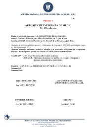
Maximum travel speed<br />
of carriage<br />
Spindle pitch:<br />
� 2mm<br />
� 4mm<br />
� 10 mm<br />
� 20 mm<br />
L 2 = profiled rail length<br />
v = travel speed<br />
Figure 5<br />
Maximum travel speed of carriage<br />
<strong>Screw</strong> drives must not be allowed to run in the critical speed range.<br />
This is dependent on the spindle length, spindle diameter<br />
and mounting arrangement. The travel speed of the carriage is<br />
dependent on the spindle pitch and the profiled rail length L 2 ,<br />
Figure 5.<br />
1100<br />
mm/s<br />
1000<br />
900<br />
800<br />
700<br />
4<br />
600<br />
3<br />
v 500<br />
400<br />
300<br />
2<br />
200<br />
1<br />
100<br />
0<br />
550 600 650 700 750 800<br />
L2 850 900 950 1000 1100<br />
mm 1050<br />
<strong>Schaeffler</strong> <strong>Group</strong> Industrial TPI 181 11<br />
00014852
<strong>Compact</strong> linear actuator<br />
<strong>with</strong> ball screw drive<br />
Lubrication The guidance systems and the ball screw drive in the compact linear<br />
actuators are supplied <strong>with</strong> an initial grease filling of a high quality<br />
lithium complex soap grease KP2P–35 to DIN 51 825 and must be<br />
relubricated during operation.<br />
Lubrication of the guidance systems The guidance systems and the ball screw drive (the contact zones<br />
between the rolling elements and raceways) must be lubricated.<br />
The relubrication intervals are essentially dependent on the carriage<br />
travel speed, the load, the operating temperature, the stroke length<br />
and the environmental conditions. The cleaner the environment,<br />
the lower the lubricant consumption.<br />
The carriage must be moved during the lubrication process.<br />
The carriage must be moved slowly during relubrication<br />
of the spindle nut (Figure 6 � or �).<br />
Relubrication should be carried out using a lithium or lithium<br />
complex soap grease <strong>with</strong> a mineral oil or poly-alpha-olefin base.<br />
If different greases are used, their miscibility and compatibility<br />
must be checked first.<br />
The viscosity of the base oil should be in the range ISO-VG 68<br />
to ISO-VG 100. The consistency corresponds to NLGI class 2.<br />
The grease must have particular anti-wear characteristics at loads of<br />
C/P � 8. This is indicated by the letter P in the DIN designation,<br />
for example: DIN 51 825–KP2P–35.<br />
Relubrication should be carried out wherever possible <strong>with</strong> several<br />
partial quantities at various times instead of the complete quantity<br />
at the time of the relubrication interval.<br />
Relubrication is carried out via three lubrication nipples on<br />
the longitudinal faces of the carriage.<br />
Lubricant must be supplied to the guidance system from the left<br />
and right (lubrication points � and �) and can be supplied to<br />
the ball screw drive from the left or right (lubrication point � or �).<br />
�, � Lubrication points for the linear<br />
recirculating ball bearing units<br />
�, � Lubrication points for the spindle nut<br />
Figure 6<br />
Lubrication points<br />
For relubrication, a conical or needlepoint grease nozzle must be<br />
used to press the lubricant into the lubrication nipple.<br />
12 TPI 181 <strong>Schaeffler</strong> <strong>Group</strong> Industrial<br />
1<br />
3<br />
2<br />
4<br />
00014863
The threads of the lubrication nipples can also be used for<br />
connection to a central lubrication system.<br />
The grease gun, lubrication nipple, vicinity of the lubrication nipple<br />
and grease must be clean.<br />
Lubrication should always be carried out <strong>with</strong> the linear actuator<br />
warm from operation.<br />
Move the carriage during lubrication.<br />
Move the carriage slowly during relubrication of the spindle nut<br />
(� or �).<br />
Calculation of lubrication intervals Since it is not possible to calculate all the influencing factors,<br />
the time at which relubrication must be carried out and the quantity<br />
of lubricant which must be used can only be precisely determined<br />
under actual operating conditions.<br />
If no precise data are available, the values for many applications can<br />
be taken from the table.<br />
Relubrication must be carried out at the latest when fretting<br />
corrosion first occurs, which is visible as a reddish discolouration<br />
of the raceways. The subsequent lubrication intervals must be<br />
shortened.<br />
An approximation formula can be used, however, to determine<br />
a guide value for many applications.<br />
Detailed information on calculating the grease operating life is given<br />
in the Catalogue PF 1, Monorail Guidance Systems.<br />
Relubrication quantity<br />
per lubrication point<br />
Design Lubrication points Relubrication quantity<br />
�g<br />
Standard � 0,5<br />
� 0,5<br />
� or � 1 per 100 mm travel distance<br />
Long carriage � 1<br />
(suffix 80)<br />
� 1<br />
� or � 1 per 100 mm travel distance<br />
Any lubrication method involves loss of lubricant.<br />
The used lubricant must be collected and disposed of by methods<br />
that help to protect the environment.<br />
The handling and use of lubricants is governed by national<br />
regulations for environmental protection and health and safety<br />
at work as well as information from the lubricant manufacturers.<br />
These specifications must be observed.<br />
<strong>Schaeffler</strong> <strong>Group</strong> Industrial TPI 181 13
<strong>Compact</strong> linear actuator<br />
<strong>with</strong> ball screw drive<br />
Location of the support rail<br />
Location using clamping lugs Clamping lugs are suitable for location of the linear actuator on<br />
the adjacent construction. If the actuator is fully supported,<br />
clamping lugs must be arranged at both ends of the support rail<br />
and then on both sides at intervals of no more than 300 mm,<br />
Figure 7.<br />
For heavy load conditions are present, the quantity of clamping lugs<br />
must be increased!<br />
Figure 7<br />
Location using clamping lugs<br />
Location using screws For location of the linear actuator on the adjacent construction,<br />
the underside of the support rail has threaded holes at intervals<br />
of 40 mm, Figure 8.<br />
The end distance T 2 is dependent on the profiled rail length and the<br />
number of holes. It is a minimum of 15 mm and a maximum of<br />
35 mm.<br />
� Threaded hole M4�15<br />
L 2 = profiled rail length<br />
T 2 =end distance<br />
Figure 8<br />
Threaded holes on the underside<br />
of the support rail<br />
T 2<br />
100<br />
114<br />
14 TPI 181 <strong>Schaeffler</strong> <strong>Group</strong> Industrial<br />
1<br />
L2<br />
40<br />
�300<br />
T2<br />
�300<br />
00014851<br />
68<br />
00014850
Final spacing value and number<br />
of threaded holes<br />
Profiled rail length Number of threaded holes<br />
(per side)<br />
End distance<br />
L2 n T2 150 3 35<br />
200 5 20<br />
250 6 25<br />
300 7 30<br />
350 7 35<br />
400 10 20<br />
450 11 25<br />
500 12 30<br />
550 13 35<br />
600 15 20<br />
650 16 25<br />
700 17 30<br />
750 18 35<br />
800 20 20<br />
850 21 25<br />
900 22 30<br />
950 23 35<br />
1000 25 20<br />
1050 26 25<br />
1100 27 30<br />
The table gives the end distance T2 for fixed profiled rail lengths,<br />
intermediate lengths can be calculated.<br />
The end distance T2 is calculated using the following formula:<br />
L2−40 ⋅( n−1)<br />
T2<br />
=<br />
2<br />
T2 mm<br />
End distance<br />
L2 mm<br />
Profiled rail length<br />
n –<br />
Number of threaded holes<br />
<strong>Schaeffler</strong> <strong>Group</strong> Industrial TPI 181 15
<strong>Compact</strong> linear actuator<br />
<strong>with</strong> ball screw drive<br />
Stroke length The standard stroke length of linear actuators MKUVS32<br />
is dependent on the profiled rail length, the carriage length,<br />
sealing and the number of carriages, Figure 9 and tables<br />
on page 16 and page 17.<br />
Other stroke lengths may be possible by agreement.<br />
� Stroke length<br />
Figure 9<br />
Stroke length<br />
Stroke length of actuators<br />
<strong>with</strong> standard carriage<br />
Profiled<br />
rail<br />
length<br />
Total length Stroke length<br />
L2 Ltot MKUVS32<br />
16 TPI 181 <strong>Schaeffler</strong> <strong>Group</strong> Industrial<br />
1<br />
-KGT -OA -KGT<br />
-OA<br />
-KGT-W2<br />
-OA-W2<br />
L2<br />
L tot<br />
-KGT-ADA<br />
-OA-ADA<br />
150 224 180 72 – – –<br />
200 274 230 122 55 68 –<br />
250 324 280 172 105 118 –<br />
300 374 330 222 155 168 47<br />
350 424 380 272 205 218 97<br />
400 474 430 322 255 268 147<br />
450 524 480 372 305 318 197<br />
500 574 530 422 355 368 247<br />
550 624 580 472 405 418 297<br />
600 674 630 522 455 468 347<br />
650 724 680 572 505 518 397<br />
700 774 730 622 555 568 447<br />
750 824 780 672 605 618 497<br />
800 874 830 722 655 668 547<br />
850 924 880 772 705 718 597<br />
900 974 930 822 755 768 647<br />
950 1 024 980 872 805 818 697<br />
1000 1 074 1030 922 855 868 747<br />
1050 1 124 1080 972 905 918 797<br />
1100 1 174 1130 1022 955 968 847<br />
00014857<br />
-KGT-ADA-W2<br />
-OA-ADA-W2
Stroke length of actuators<br />
<strong>with</strong> long carriage<br />
Profiled<br />
rail<br />
length<br />
Total length Stroke length<br />
L2 Ltot MKUVS32-80<br />
-KGT -OA -KGT<br />
-OA<br />
-KGT-W2<br />
-OA-W2<br />
-KGT-ADA<br />
-OA-ADA<br />
200 274 230 72 – – –<br />
250 324 280 122 – 68 –<br />
300 374 330 172 55 118 –<br />
350 424 380 222 105 168 –<br />
400 474 430 272 155 218 47<br />
450 524 480 322 205 268 97<br />
500 574 530 372 255 318 147<br />
550 624 580 422 305 368 197<br />
600 674 630 472 355 418 247<br />
650 724 680 522 405 468 297<br />
700 774 730 572 455 518 347<br />
750 824 780 622 505 568 397<br />
800 874 830 672 555 618 447<br />
850 924 880 722 605 668 497<br />
900 974 930 772 655 718 547<br />
950 1 024 980 822 705 768 597<br />
1000 1 074 1 030 872 755 818 647<br />
1050 1 124 1 080 922 805 868 697<br />
1100 1 174 1 130 972 855 918 747<br />
-KGT-ADA-W2<br />
-OA-ADA-W2<br />
<strong>Schaeffler</strong> <strong>Group</strong> Industrial TPI 181 17
<strong>Compact</strong> linear actuator<br />
<strong>with</strong> ball screw drive<br />
Accuracy<br />
Support rail The support rail of the compact linear actuator is precision<br />
straightened. The tolerances are maximum values and are not valid<br />
for unmounted support rails. When mounted, the shape of the<br />
extruded profile adapts to the mounting surface. The method<br />
for determining the straightness of the support rail is shown in<br />
Figure 10.<br />
Straightness tolerance<br />
of support rail<br />
Length tolerance<br />
of support rail<br />
Figure 10<br />
Straightness tolerance<br />
of support rail<br />
Length of support rail MKUVS32<br />
L2 mm<br />
t2 mm<br />
18 TPI 181 <strong>Schaeffler</strong> <strong>Group</strong> Industrial<br />
t 3<br />
mm<br />
L 2 � 1 100 0,4 0,3 0,8<br />
Length of support rail MKUVS32<br />
L2 Tolerance<br />
mm<br />
mm<br />
L2 � 1 100 �0,5<br />
t3 t2 Torsion<br />
mm<br />
00014854
Accessories<br />
Sensors For linear actuators MKUVS32, end position and<br />
zero point sensors are available in various configurations,<br />
see table Designation of sensors, page 20.<br />
Typical end position sensors are designed as openers,<br />
typical zero point sensors as closers, Figure 11,<br />
and connection scheme, Figure 13, page 20.<br />
The sensors contain Hall effect elements that detect a magnet<br />
integrated in the side of the drive carriage.<br />
For ease of mounting, the sensors are supplied <strong>with</strong> a 300 mm long<br />
cable and an M8 3 pin industry standard connector.<br />
In addition, a matching 5 metre long cable is available <strong>with</strong> a plug at<br />
one end and bare cable ends at the other.<br />
� End position sensor<br />
� Zero point sensor<br />
� M8 3 pin plug<br />
� Connection cable<br />
Figure 11<br />
End position and zero point sensors<br />
� LED<br />
� Fixing screw<br />
� Widened slot for sensor mounting,<br />
on drive side only<br />
Figure 12<br />
Location of sensors<br />
The individual sensors are located flush in a lateral slot in the<br />
support rail, Figure 12. The sensors can be arranged at any point<br />
over the entire length of the linear actuator and are fixed in place by<br />
means of a set screw in the sensor head.<br />
<strong>Schaeffler</strong> <strong>Group</strong> Industrial TPI 181 19<br />
1<br />
2<br />
1<br />
3<br />
38<br />
4<br />
2<br />
3<br />
1<br />
00014866<br />
00014865
� PNP logic<br />
� NPN logic<br />
� BRN<br />
� BLK<br />
� BLU<br />
Figure 13<br />
Connection scheme<br />
Designation of sensors<br />
Designation of the connection cable<br />
<strong>Compact</strong> linear actuator<br />
<strong>with</strong> ball screw drive<br />
Coupling housing cover The openings above and below the coupling housing can be closed<br />
off using a cover, Figure 14.<br />
The cover and mounting material are available as a set.<br />
� Upper coupling housing cover<br />
� Lower coupling housing cover<br />
Figure 14<br />
Coupling housing cover<br />
Designation<br />
of coupling housing covers<br />
20 TPI 181 <strong>Schaeffler</strong> <strong>Group</strong> Industrial<br />
3<br />
4<br />
5<br />
+<br />
_<br />
1 2<br />
Designation Logic Design Voltage Switched<br />
current<br />
max.<br />
INI-CS-50NNC-QD NPN logic Closer 10–30 V DC 100 mA<br />
INI-CS-40TN-QD NPN logic Opener 10–30 V DC 100 mA<br />
INI-CS-50PNC-QD PNP logic Closer 10–30 V DC 100 mA<br />
INI-CS-40TP-QD PNP logic Opener 10–30 V DC 100 mA<br />
Designation Description<br />
NI-M83R-PUR-5M Connection cable for sensors INI-CS-..-QD<br />
Length 5 mm<br />
2<br />
1<br />
Designation Description<br />
ADH.MKUVS32-KGT-0400 upper and lower coupling housing covers<br />
<strong>with</strong> fixing material<br />
3<br />
4<br />
5<br />
+<br />
_<br />
000148F4<br />
0001485A
Motor adapter plates In order to mount a motor on the linear actuator MKUVS32,<br />
an adapter plate is required; for available designs see<br />
dimension table page 34.<br />
Other adapter plates are available by agreement.<br />
Couplings For linear actuators MKUVS32, worm couplings or cross couplings<br />
are available, see dimension tables page 32 and page 33,<br />
as well as Figure 15 and Figure 16. They are clamped to the drive<br />
shaft and motor shaft to transmit the drive torque.<br />
Figure 15<br />
Worm coupling KUP-H 00014A82<br />
Figure 16<br />
Cross coupling KUP-S 00014A84<br />
<strong>Schaeffler</strong> <strong>Group</strong> Industrial TPI 181 21
<strong>Compact</strong> linear actuator<br />
<strong>with</strong> ball screw drive<br />
Clamping lugs Clamping lugs are required for location of the support rail on the<br />
adjacent construction, Figure 17. They are made from anodised<br />
aluminium.<br />
Figure 17<br />
Dimensions of clamping lug<br />
Design of clamping lug<br />
5,5<br />
12<br />
22 TPI 181 <strong>Schaeffler</strong> <strong>Group</strong> Industrial<br />
7<br />
� 11<br />
� 7<br />
20<br />
Designation Description<br />
SPPR12�20 Clamping lug<br />
5<br />
8<br />
20<br />
00014A44
Ordering example,<br />
ordering designation<br />
Ordering designation MKUVS32-80-KGT/2-ADA-W2/550-197, Figure 18<br />
Figure 18<br />
Ordering example,<br />
ordering designation<br />
<strong>Compact</strong> linear actuator <strong>with</strong> ball screw drive MKUVS<br />
Size 32<br />
Carriage length 80<br />
<strong>Drive</strong> by ball screw drive KGT<br />
Spindle pitch 2 mm<br />
Strip cover ADA<br />
2 carriages (non-driven) W2<br />
Guideway length 550 mm<br />
Total stroke length 197 mm<br />
MKUVS32-80-KGT/2-ADA-W2/550-197<br />
<strong>Schaeffler</strong> <strong>Group</strong> Industrial TPI 181 23<br />
550<br />
197<br />
00014A47
<strong>Compact</strong> linear actuators<br />
<strong>with</strong> ball screw drive<br />
<strong>Linear</strong> actuator <strong>with</strong> one carriage<br />
<strong>with</strong>out strip cover<br />
Dimension table · Dimensions in mm<br />
MKUVS32-KGT<br />
24 TPI 181 <strong>Schaeffler</strong> <strong>Group</strong> Industrial<br />
00014A40<br />
15<br />
10,5<br />
1) Total stroke length = effective stroke length + 2 · S (mm)<br />
S = The allowance S designates a safety range suitable for the particular application<br />
and should be at least two thread turns.<br />
L2 = Total stroke length + L1 + 21<br />
Ltot = Total stroke length + L1 + 95 for linear actuator <strong>with</strong> ball screw drive (suffix KGT)<br />
Ltot = Total stroke length + L1 + 51 for linear actuator <strong>with</strong>out drive (suffix OA)<br />
2) L2 max = 1100 mm for spindle pitch 10 mm and 20 mm<br />
L2 max = 550 mm for spindle pitch 2 mm and 4 mm.<br />
3) The values are single loads and apply if the underside of the actuator is fully supported.<br />
If combined loads are present, please contact us for rating life calculation.<br />
4) d0�p = nominal diameter�spindle pitch.<br />
5) mLaw = Mass of carriage.<br />
6) Dynamic and axial loads for the spindle bearing arrangement.<br />
Applications must not exceed an axial load of 510 N.<br />
1)<br />
Ltot L 2)<br />
2<br />
L3<br />
L1<br />
L<br />
Designation Spindle Mass Dimensions<br />
MKUVS32-KGT/2 10X2<br />
MKUVS32-KGT/4 10X4<br />
MKUVS32-KGT/10 10X10<br />
MKUVS32-KGT/20 10X20<br />
d 0�p 4) m tot m Law 5)<br />
�kg �kg<br />
(L 2 · 0,0055) � 0,67 0,3<br />
MKUVS32-OA – (L 2 · 0,0049) � 0,58 0,21<br />
MKUVS32-80-KGT/2 10X2<br />
MKUVS32-80-KGT/4 10X4<br />
MKUVS32-80-KGT/10 10X10<br />
MKUVS32-80-KGT/20 10X20<br />
(L 2 · 0,0055) � 0,94 0,58<br />
MKUVS32-80-OA – (L 2 · 0,0049) � 0,85 0,49<br />
00014834<br />
M z<br />
Load directions (schematic)<br />
59<br />
36,5<br />
L L 1 L 3<br />
30 57 61<br />
80 107 111<br />
M y<br />
X<br />
M x<br />
Y<br />
12<br />
�5<br />
Z
00014A42<br />
15<br />
10,5<br />
MKUVS32-OA<br />
7)<br />
1)<br />
L tot<br />
L2<br />
L3<br />
L1<br />
L<br />
Carriage<br />
�, � 7)<br />
<strong>Schaeffler</strong> <strong>Group</strong> Industrial TPI 181 25<br />
0001486c<br />
64<br />
59�0,02 L<br />
15<br />
L1<br />
L3<br />
1<br />
2<br />
20 �0,02<br />
64<br />
59�0,02 Basic load ratings Static moment rating<br />
of linear guidance system 3)<br />
L<br />
15 50<br />
L1<br />
L3<br />
20 �0,02<br />
Geometrical<br />
moments<br />
of inertia<br />
of support rail<br />
Carriage guidance<br />
system 3)<br />
Spindle nut Spindle bearing<br />
arrangement 6)<br />
M0x M0y M0z Iy Iz Cy , Cz C0y , C0z Cx C0x Cx C0x N N N N N N Nm Nm Nm cm4 cm4 2 133 5300<br />
5700 10 600<br />
2 370<br />
2 607<br />
5200<br />
5900<br />
1810 1 520<br />
167 46 46 83 14<br />
1 659 4000<br />
– – – –<br />
2 133 5300<br />
9300 21 200<br />
2 370<br />
2 607<br />
5200<br />
5900<br />
1810 1 520<br />
334 342 342 83 14<br />
1 659 4000<br />
– – – –<br />
00014864<br />
� Threaded hole M5�10<br />
� Hole �3 H7 �4<br />
� Hole �42 H7 �3,5<br />
� Threaded hole M4�12<br />
37,5<br />
30,85<br />
40°<br />
4<br />
3<br />
78<br />
76<br />
80<br />
MKUVS32 MKUVS32, drive side<br />
�, � 7)<br />
48<br />
00014867<br />
29,5<br />
3<br />
46<br />
4<br />
28<br />
15,75<br />
2<br />
1
<strong>Compact</strong> linear actuators<br />
<strong>with</strong> ball screw drive<br />
<strong>Linear</strong> actuator <strong>with</strong> one carriage<br />
<strong>with</strong> strip cover<br />
Dimension table · Dimensions in mm<br />
MKUVS32-KGT..-ADA<br />
26 TPI 181 <strong>Schaeffler</strong> <strong>Group</strong> Industrial<br />
00014832<br />
15<br />
10,5<br />
1) Total stroke length = effective stroke length + 2 · S (mm)<br />
S = The allowance S designates a safety range suitable for the particular application<br />
and should be at least two thread turns.<br />
L2 = Total stroke length + L1 + 21<br />
Ltot = Total stroke length + L1 + 95 for linear actuator <strong>with</strong> ball screw drive (suffix KGT)<br />
Ltot = Total stroke length + L1 + 51 for linear actuator <strong>with</strong>out drive (suffix OA)<br />
2) L2 max = 1100 mm for spindle pitch 10 mm and 20 mm<br />
L2 max = 550 mm for spindle pitch 2 mm and 4 mm.<br />
3) The values are single loads and apply if the underside of the actuator is fully supported.<br />
If combined loads are present, please contact us for rating life calculation.<br />
4) d0�p =nominal diameter�spindle pitch.<br />
5) mLaw =Mass of carriage.<br />
6) Dynamic and axial loads for the spindle bearing arrangement.<br />
Applications must not exceed an axial load of 510 N.<br />
1)<br />
Ltot L 2)<br />
2<br />
L3<br />
L1<br />
L<br />
Designation Spindle Mass Dimensions<br />
MKUVS32-KGT/2-ADA 10X2<br />
MKUVS32-KGT/4-ADA 10X4<br />
MKUVS32-KGT/10-ADA 10X10<br />
MKUVS32-KGT/20-ADA 10X20<br />
d 0�p 4) m tot m Law 5)<br />
�kg �kg<br />
(L 2 · 0,0056) � 0,72 0,35<br />
MKUVS32-OA-ADA – (L 2 · 0,0050) � 0,63 0,26<br />
MKUVS32-80-KGT/2-ADA 10X2<br />
MKUVS32-80-KGT/4-ADA 10X4<br />
MKUVS32-80-KGT/10-ADA 10X10<br />
MKUVS32-80-KGT/20-ADA 10X20<br />
(L 2 · 0,0056) � 0,99 0,62<br />
MKUVS32-80-OA-ADA – (L 2 · 0,0050) � 0,90 0,53<br />
00014834<br />
M z<br />
Load directions (schematic)<br />
59<br />
36,5<br />
L L 1 L 3<br />
30 111 117<br />
80 161 167<br />
M y<br />
X<br />
M x<br />
Y<br />
12<br />
�5<br />
Z
0001485f<br />
15<br />
10,5<br />
MKUVS32-OA..-ADA<br />
7)<br />
1)<br />
L tot<br />
L2<br />
L3<br />
L1<br />
L<br />
Carriage<br />
�, � 7)<br />
20�0,02<br />
L1<br />
L3<br />
<strong>Schaeffler</strong> <strong>Group</strong> Industrial TPI 181 27<br />
0001486D<br />
64<br />
59�0,02<br />
Basic load ratings Static moment rating<br />
of linear guidance system 3)<br />
Carriage guidance<br />
system 3)<br />
Spindle nut Spindle bearing<br />
arrangement 6)<br />
15<br />
L<br />
50<br />
2<br />
1<br />
64<br />
59�0,02<br />
15<br />
L 1<br />
2<br />
L1<br />
L3<br />
Geometrical<br />
moments<br />
of inertia<br />
of support rail<br />
M 0x M 0y M 0z I y I z<br />
Cy , Cz C0y , C0z Cx C0x Cx C0x N N N N N N Nm Nm Nm cm4 cm4 2133 5300<br />
5700 10 600<br />
2370<br />
2607<br />
5200<br />
5900<br />
1 810 1520<br />
167 46 46 83 14<br />
1659 4000<br />
– – – –<br />
2133 5300<br />
9300 21 200<br />
2370<br />
2607<br />
5200<br />
5900<br />
1 810 1520<br />
334 342 342 83 14<br />
1659 4000<br />
– – – –<br />
00014864<br />
� Threaded hole M5�10<br />
� Hole �3 H7 �4<br />
� Hole �42 H7 �3,5<br />
� Threaded hole M4�12<br />
37,5<br />
30,85<br />
40°<br />
4<br />
3<br />
78<br />
76<br />
80<br />
MKUVS32 MKUVS32, drive side<br />
�, � 7)<br />
48<br />
00014867<br />
29,5<br />
3<br />
46<br />
4<br />
20 �0,02<br />
28<br />
15,75
<strong>Compact</strong> linear actuators<br />
<strong>with</strong> ball screw drive<br />
<strong>Linear</strong> actuator <strong>with</strong> two carriages<br />
<strong>with</strong>out strip cover<br />
Dimension table · Dimensions in mm<br />
MKUVS32-KGT-W2<br />
28 TPI 181 <strong>Schaeffler</strong> <strong>Group</strong> Industrial<br />
00014A41<br />
15<br />
10,5<br />
L3<br />
L1<br />
L<br />
L 1)<br />
tot<br />
2)<br />
L2<br />
Designation Spindle Mass Dimensions<br />
MKUVS32-KGT/2-W2 10X2<br />
MKUVS32-KGT/4-W2 10X4<br />
MKUVS32-KGT/10-W2 10X10<br />
MKUVS32-KGT/20-W2 10X20<br />
d 0�p 4) m tot m Law 5)<br />
<strong>Drive</strong>n Non-driven<br />
�kg �kg �kg<br />
(L 2 · 0,0055) � 0,89 0,3<br />
MKUVS32-OA-ADA – (L 2 · 0,0049) � 0,8 –<br />
MKUVS32-80-KGT/2-W2 10X2<br />
MKUVS32-80-KGT/4-W2 10X4<br />
MKUVS32-80-KGT/10-W2 10X10<br />
MKUVS32-80-KGT/20-W2 10X20<br />
(L 2 · 0,0055) � 1,43 0,58<br />
MKUVS32-80-OA-W2 – (L 2 · 0,0049) � 1,34 –<br />
1) Total stroke length = effective stroke length + 2 · S (mm)<br />
S = The allowance S designates a safety range suitable for the particular application<br />
and should be at least two thread turns.<br />
L2 = Total stroke length + 2�L1 + L4 + 21<br />
Ltot = Total stroke length + 2�L1 + L4 + 95 for linear actuator <strong>with</strong> ball screw drive (suffix KGT)<br />
Ltot = Total stroke length + 2�L1 + L4 + 51 for linear actuator <strong>with</strong>out drive (suffix OA)<br />
L4 = Distance between carriage centres.<br />
In linear actuators <strong>with</strong> ball screw drive, one carriage is driven<br />
(connected to the spindle), while the other is freely movable.<br />
In linear actuators <strong>with</strong>out drive, both carriages are freely movable.<br />
L4 min = L1 + 10<br />
2) L2 max = 1100 mm for spindle pitch 10 mm and 20 mm<br />
L2 max = 550 mm for spindle pitch 2 mm and 4 mm.<br />
00014834<br />
M z<br />
M y<br />
X<br />
Load directions (schematic) MKUVS32-KGT-W2<br />
M x<br />
Y<br />
Z<br />
00014862<br />
L3<br />
L1<br />
L<br />
59<br />
36,5<br />
L L 1 L 3<br />
12<br />
0,21 30 57 61<br />
0,49 80 107 111<br />
L 4<br />
�5
00014A43<br />
15<br />
10,5<br />
MKUVS32-OA-ADA<br />
1)<br />
Ltot<br />
L2<br />
L3<br />
L1<br />
L<br />
L3<br />
L1<br />
L<br />
Carriage<br />
�, � 8)<br />
<strong>Schaeffler</strong> <strong>Group</strong> Industrial TPI 181 29<br />
0001486c<br />
64<br />
59�0,02 L<br />
15<br />
L1<br />
L3<br />
1<br />
2<br />
20 �0,02<br />
3) The values are single loads and apply if the underside of the actuator is fully supported.<br />
If combined loads are present, please contact us for rating life calculation.<br />
4) d0�p = nominal diameter�spindle pitch.<br />
5) mLaw =Mass of carriage.<br />
6) Dynamic and axial loads for the spindle bearing arrangement.<br />
Applications must not exceed an axial load of 510 N.<br />
7) Attention! M0y and M0z are dependent on L4. For calculation of applications <strong>with</strong> moment loads, please contact us.<br />
8) � Threaded hole M5�10<br />
� Hole �3H7�4 � Hole �42H7�3,5 � Threaded hole M4�12<br />
64<br />
59�0,02 Basic load ratings Static moment rating<br />
of linear guidance system 3)<br />
Carriage guidance<br />
system 3)<br />
Spindle nut Spindle bearing<br />
arrangement 6)<br />
M 0x<br />
M 0y 7)<br />
M 0z 7)<br />
L<br />
15 50<br />
L1<br />
L3<br />
20 �0,02<br />
Geometrical<br />
moments<br />
of inertia<br />
of support rail<br />
C y , C z C 0y , C 0z C x C 0x C x C 0x<br />
N N N N N N Nm Nm Nm cm 4 cm 4<br />
9300 21 200<br />
15 000 42 400<br />
00014864<br />
37,5<br />
30,85<br />
40°<br />
2133 5300<br />
2370 5200<br />
2607 5900<br />
1659 4000<br />
1 810 1520<br />
– – – –<br />
2133 5300<br />
2370 5200<br />
2607 5900<br />
1659 4000<br />
1 810 1520<br />
– – – –<br />
78<br />
76<br />
MKUVS32 MKUVS32, drive side<br />
�, � 8)<br />
3<br />
80<br />
4<br />
48<br />
00014867<br />
29,5<br />
3<br />
334 – – 83 14<br />
669 – – 83 14<br />
46<br />
I y<br />
4<br />
I z<br />
28<br />
15,75<br />
2<br />
1
<strong>Compact</strong> linear actuators<br />
<strong>with</strong> ball screw drive<br />
<strong>Linear</strong> actuator <strong>with</strong> two carriages<br />
<strong>with</strong> strip cover<br />
Dimension table · Dimensions in mm<br />
MKUVS32-KGT..-ADA-W2<br />
30 TPI 181 <strong>Schaeffler</strong> <strong>Group</strong> Industrial<br />
00014833<br />
15<br />
10,5<br />
L3<br />
L1<br />
L<br />
L 1)<br />
tot<br />
L 2)<br />
2<br />
Designation Spindle Mass Dimensions<br />
MKUVS32-KGT/2-ADA-W2 10X2<br />
MKUVS32-KGT/4-ADA-W2 10X4<br />
MKUVS32-KGT/10-ADA-W2 10X10<br />
MKUVS32-KGT/20-ADA-W2 10X20<br />
d 0�p 4) m tot m Law 5)<br />
<strong>Drive</strong>n Non-driven<br />
�kg �kg �kg<br />
(L 2 · 0,0056) � 0,98 0,35<br />
MKUVS32-OA-ADA-W2 – (L 2 · 0,0050) � 0,89 –<br />
MKUVS32-80-KGT/2-ADA-W2 10X2<br />
MKUVS32-80-KGT/4-ADA-W2 10X4<br />
MKUVS32-80-KGT/10-ADA-W2 10X10<br />
MKUVS32-80-KGT/20-ADA-W2 10X20<br />
(L 2 · 0,0056) � 1,52 0,62<br />
MKUVS32-80-OA-ADA-W2 – (L 2 · 0,0050) � 1,43 –<br />
1) Total stroke length = effective stroke length + 2 · S (mm)<br />
S = The allowance S designates a safety range suitable for the particular application<br />
and should be at least two thread turns.<br />
L2 = Total stroke length + 2�L1 + L4 + 21<br />
Ltot = Total stroke length + 2�L1 + L4 + 95 for linear actuator <strong>with</strong> ball screw drive (suffix KGT)<br />
Ltot = Total stroke length + 2�L1 + L4 + 51 for linear actuator <strong>with</strong>out drive (suffix OA)<br />
L4 = Distance between carriage centres.<br />
In linear actuators <strong>with</strong> ball screw drive, one carriage is driven<br />
(connected to the spindle), while the other is freely movable.<br />
In linear actuators <strong>with</strong>out drive, both carriages are freely movable.<br />
L4 min = L1 + 10<br />
2) L2 max = 1100 mm for spindle pitch 10 mm and 20 mm<br />
L2 max = 550 mm for spindle pitch 2 mm and 4 mm.<br />
00014834<br />
M z<br />
M y<br />
X<br />
M x<br />
Y<br />
Load directions (schematic) MKUVS32-KGT..-ADA-W2<br />
Z<br />
00014862<br />
L3<br />
L1<br />
L<br />
59<br />
36,5<br />
L L 1 L 3<br />
12<br />
0,26 30 111 117<br />
0,53 80 161 167<br />
L 4<br />
�5
00014861<br />
15<br />
10,5<br />
MKUVS32-OA..-W2<br />
1)<br />
Ltot<br />
L2<br />
L3<br />
L1<br />
L<br />
L3<br />
L1<br />
L<br />
Carriage<br />
�, � 8)<br />
20�0,02<br />
L1<br />
L3<br />
<strong>Schaeffler</strong> <strong>Group</strong> Industrial TPI 181 31<br />
0001486D<br />
64<br />
59�0,02<br />
Basic load ratings Static moment rating<br />
of linear guidance system 3)<br />
Carriage guidance<br />
system 3)<br />
Spindle nut Spindle bearing<br />
arrangement 6)<br />
3) The values are single loads and apply if the underside of the actuator is fully supported.<br />
If combined loads are present, please contact us for rating life calculation.<br />
4) d0�p = nominal diameter�spindle pitch.<br />
5) mLaw =Mass of carriage.<br />
6) Dynamic and axial loads for the spindle bearing arrangement.<br />
Applications must not exceed an axial load of 510 N.<br />
7) Attention! M0y and M0z are dependent on L4. For calculation of applications <strong>with</strong> moment loads, please contact us.<br />
8) � Threaded hole M5�10<br />
� Hole �3H7�4 � Hole �42H7�3,5 � Threaded hole M4�12<br />
15<br />
M 0x<br />
L<br />
50<br />
M 0y 7)<br />
2<br />
1<br />
64<br />
59�0,02<br />
M 0z 7)<br />
15<br />
L 1<br />
2<br />
L1<br />
L3<br />
Geometrical<br />
moments<br />
of inertia<br />
of support rail<br />
C y , C z C 0y , C 0z C x C 0x C x C 0x<br />
N N N N N N Nm Nm Nm cm 4 cm 4<br />
9300 21 200<br />
15 000 42 400<br />
00014864<br />
37,5<br />
30,85<br />
40°<br />
2133 5300<br />
2370 5200<br />
2607 5900<br />
1659 4000<br />
1 810 1520<br />
– – – –<br />
2133 5300<br />
2370 5200<br />
2607 5900<br />
1659 4000<br />
1 810 1520<br />
– – – –<br />
78<br />
76<br />
MKUVS32 MKUVS32, drive side<br />
�, � 8)<br />
3<br />
80<br />
4<br />
48<br />
00014867<br />
29,5<br />
3<br />
334 – – 83 14<br />
669 – – 83 14<br />
46<br />
I y<br />
4<br />
20 �0,02<br />
I z<br />
28<br />
15,75
Accessories<br />
Worm couplings<br />
Dimension table · Dimensions in mm<br />
KUP-H<br />
Designation Dimensions Dynamic<br />
torque<br />
D1 D<br />
32 TPI 181 <strong>Schaeffler</strong> <strong>Group</strong> Industrial<br />
D2<br />
L<br />
L1<br />
L1<br />
Mass moment<br />
of inertia<br />
1) Worm couplings have a through hole. This allows the drive shafts to be located deep in the coupling.<br />
The drive shafts must not come into contact <strong>with</strong> each other in the coupling.<br />
<strong>Screw</strong><br />
tightening<br />
torque<br />
D L D1 D2 L1 Mnom Mm MA mm inch Nm kg · m2 Nm<br />
KUP-H-25-5-6 25 31 5 6 – 9 0,9 2,96X10�6 1,34<br />
KUP-H-25-5-6,35 25 31 5 6,35 1<br />
/4 9 0,9 2,96X10�6 1,34<br />
KUP-H-25-5-8 25 31 5 8 – 9 0,9 2,96X10�6 1,34<br />
KUP-H-25-5-9,53 25 31 5 9,53 3<br />
/8 9 0,8 2,96X10�6 1,34<br />
0001485B
Accessories<br />
Cross couplings<br />
Dimension table · Dimensions in mm<br />
KUP-S<br />
D3 D2<br />
Designation Dimensions Dynamic<br />
torque<br />
L1 L<br />
L2L1<br />
D1 D<br />
1) Cross couplings have a urethane crosspiece at the centre that prevents the shafts from passing fully through the bore.<br />
<strong>Schaeffler</strong> <strong>Group</strong> Industrial TPI 181 33<br />
L 3<br />
Mass<br />
moment<br />
of inertia<br />
<strong>Screw</strong><br />
tightening<br />
torque<br />
D L D1 D2 D3 L1 L2 L3 Mnom Mm MA mm inch Nm kg · m2 Nm<br />
KUP-S-9-5-2,0-6-2,0 20 30 5 6 – 7,2 10 8 1,5 1,5 1,06X10�6 0,76<br />
KUP-S-9-5-2,0-6,35-2,0 20 30 5 6,35 1 / 4 7,2 10 8 1,5 1,5 1,06X10�6 0,76<br />
KUP-S-9-5-2,0-7,94-2,0 20 30 5 7,94 5 / 16 7,2 10 8 1,5 1,5 1,06X10�6 0,76<br />
KUP-S-9-5-2,0-8-2,0 20 30 5 8 – 7,2 10 8 1,5 1,5 1,06X10�6 0,76<br />
KUP-S-14-5-2,0-9,53-2,0 30 35 5 9,53 3 / 8 10,5 11 10 2 3,3 6,06X10�6 1,34<br />
KUP-S-14-5-2,0-10-2,0 30 35 5 10 – 10,5 11 10 2 3,3 6,06X10�6 1,34<br />
KUP-S-14-5-2,0-12-2,0 30 35 5 12 – 10,5 11 10 2 3,3 6,06X10�6 1,34<br />
KUP-S-14-5-2,0-12,7-2,0 30 35 5 12,7 1<br />
/2 10,5 11 10 2 3,3 6,06X10�6 1,34<br />
KUP-S-14-5-2,0-14-2,0 30 35 5 14 – 10,5 11 10 2 3,3 6,06X10�6 1,34<br />
KUP-S-14-5-2,0-16-2,0 30 35 5 16 – 10,5 11 10 2 3,3 6,06X10�6 1,34<br />
0001485c
Accessories<br />
Motor adapter plates<br />
Dimension table · Dimensions in mm<br />
1) Shaft length – adapter plate to end of motor shaft.<br />
2) The notation D2 in the coupling designation indicates the bore for the motor shaft.<br />
3) � Through hole for thread S.<br />
Mounting dimensions for motor adapter plates<br />
� 3)<br />
Designation Mounting dimensions Suitable for coupling 2)<br />
SL 1) PD BC S<br />
APL.MKUVS32-KGT-001-0701 14 – 28 38,1 66,7 M4 KUP-H-25-5-D2 for 14 � SL � 28<br />
KUP-S-9-5-2,0-D2-2,0 for 19 � SL � 21<br />
APL.MKUVS32-KGT-002-0701 14 – 28 30 46 M4 KUP-H-25-5-X for 14 � SL � 28<br />
KUP-S-9-5-2,0-X-2,0 for 19 � SL � 23<br />
APL.MKUVS32-KGT-003-0701 30 50 70 M5 KUP-S-14-5-2,0-D2-2,0 APL.MKUVS32-KGT-004-0701 30 – 44 38,1 66,7 M4 KUP-H-25-5-D2 for 31 � SL � 44<br />
KUP-S-9-5-2,0-D2-2,0 for 35 � SL � 37<br />
KUP-S-14-5-2,0-D2-2,0 for 30 � SL � 37<br />
APL.MKUVS32-KGT-005-0701 25 50 70 M5 KUP-H-25-5-D2 APL.MKUVS32-KGT-006-0701 40 110 145 M8 KUP-S-14-5-2,0-D2-2,0 APL.MKUVS32-KGT-007-0701 20 40 63 M4 KUP-S-9-5-2,0-D2-2,0 APL.MKUVS32-KGT-008-0701 22,7 60 75 M5 KUP-S-9-5-2,0-D2-2,0 APL.MKUVS32-KGT-009-0701 31 73,03 98,43 M5 KUP-S-14-5-2,0-D2-2,0 APL.MKUVS32-KGT-010-0701 40 70 90 M6 KUP-S-14-5-2,0-D2-2,0 APL.MKUVS32-KGT-011-0701 30 70 90 M6 KUP-S-14-5-2,0-D2-2,0 APL.MKUVS32-KGT-012-0701 40 80 100 M6 KUP-S-14-5-2,0-D2-2,0 APL.MKUVS32-KGT-013-0701 25 25 40 M5 KUP-H-25-5-D2 �3,5mm<br />
Mounting dimensions for motor adapter plates<br />
SL<br />
D 2<br />
0001485E<br />
34 TPI 181 <strong>Schaeffler</strong> <strong>Group</strong> Industrial<br />
PD<br />
BC<br />
1<br />
0001485D
MATNR 036784290-0000 / TPI 181 / GB-D / 2010041 / Printed in Germany by hofmann<br />
<strong>Schaeffler</strong> Technologies<br />
GmbH & Co. KG<br />
<strong>Linear</strong> Technology Division<br />
Berliner Straße 134<br />
66424 Homburg/Saar (Germany)<br />
Internet www.ina.com<br />
E-Mail info.linear@schaeffler.com<br />
In Germany:<br />
Phone 0180 5003872<br />
Fax 0180 5003873<br />
From other countries:<br />
Phone +49 6841 701-0<br />
Fax +49 6841 701-2625<br />
Every care has been taken to ensure the<br />
correctness of the information contained<br />
in this publication but no liability can be<br />
accepted for any errors or omissions.<br />
We reserve the right to make technical<br />
changes.<br />
© <strong>Schaeffler</strong> Technologies GmbH & Co. KG<br />
Issued: 2010, april<br />
This publication or parts thereof may not<br />
be reproduced <strong>with</strong>out our permission.<br />
TPI 181 GB-D