XV-15 litho - NASA's History Office
XV-15 litho - NASA's History Office
XV-15 litho - NASA's History Office

Create successful ePaper yourself
Turn your PDF publications into a flip-book with our unique Google optimized e-Paper software.
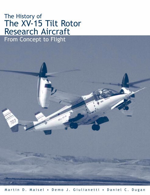
The <strong>History</strong> of<br />
The <strong>XV</strong>-<strong>15</strong> Tilt Rotor<br />
Research Aircraft<br />
From Concept to Flight<br />
Martin D. Maisel • Demo J. Giulianetti • Daniel C. Dugan
NASA SP-2000-4517<br />
The <strong>History</strong> of the<br />
<strong>XV</strong>-<strong>15</strong> Tilt Rotor Research Aircraft:<br />
From Concept to Flight<br />
Martin D. Maisel<br />
Demo J. Giulianetti<br />
and<br />
Daniel C. Dugan<br />
Monographs in Aerospace <strong>History</strong> #17<br />
The NASA <strong>History</strong> Series<br />
National Aeronautics and Space Administration<br />
<strong>Office</strong> of Policy and Plans<br />
NASA <strong>History</strong> Division<br />
Washington, D.C.<br />
2000
Contents<br />
Prologue . . . . . . . . . . . . . . . . . . . . . . . . . . . . . . . . . . . . . . . . . . . . . . . . . . . . . . . iii<br />
Dedication . . . . . . . . . . . . . . . . . . . . . . . . . . . . . . . . . . . . . . . . . . . . . . . . . . . . . . v<br />
Acknowledgments . . . . . . . . . . . . . . . . . . . . . . . . . . . . . . . . . . . . . . . . . . . . . . . vii<br />
Forewords . . . . . . . . . . . . . . . . . . . . . . . . . . . . . . . . . . . . . . . . . . . . . . . . . . . . . . ix<br />
List of Figures . . . . . . . . . . . . . . . . . . . . . . . . . . . . . . . . . . . . . . . . . . . . . . . . . xiii<br />
List of Acronyms . . . . . . . . . . . . . . . . . . . . . . . . . . . . . . . . . . . . . . . . . . . . . . . xix<br />
Introduction . . . . . . . . . . . . . . . . . . . . . . . . . . . . . . . . . . . . . . . . . . . . . . . . . . . . . 1<br />
Early Efforts. . . . . . . . . . . . . . . . . . . . . . . . . . . . . . . . . . . . . . . . . . . . . . . . . . . . . 4<br />
<strong>XV</strong>-3 Program . . . . . . . . . . . . . . . . . . . . . . . . . . . . . . . . . . . . . . . . . . . . . . . . . . 12<br />
NASA-Army Cooperation . . . . . . . . . . . . . . . . . . . . . . . . . . . . . . . . . . . . . . . . . 19<br />
Building the Technology Base. . . . . . . . . . . . . . . . . . . . . . . . . . . . . . . . . . . . . . 20<br />
Tilt Rotor Research Aircraft Project <strong>Office</strong>. . . . . . . . . . . . . . . . . . . . . . . . . . . . 28<br />
Aircraft Development . . . . . . . . . . . . . . . . . . . . . . . . . . . . . . . . . . . . . . . . . . . . 42<br />
Navy Participation . . . . . . . . . . . . . . . . . . . . . . . . . . . . . . . . . . . . . . . . . . . . . . . 59<br />
Flight Envelope Expansion . . . . . . . . . . . . . . . . . . . . . . . . . . . . . . . . . . . . . . . . 61<br />
Flight Research . . . . . . . . . . . . . . . . . . . . . . . . . . . . . . . . . . . . . . . . . . . . . . . . . 65<br />
Incidents. . . . . . . . . . . . . . . . . . . . . . . . . . . . . . . . . . . . . . . . . . . . . . . . . . . . . . . 83<br />
Paris Air Show . . . . . . . . . . . . . . . . . . . . . . . . . . . . . . . . . . . . . . . . . . . . . . . . . . 88<br />
Evaluations and Demonstrations . . . . . . . . . . . . . . . . . . . . . . . . . . . . . . . . . . . . 91<br />
Crash . . . . . . . . . . . . . . . . . . . . . . . . . . . . . . . . . . . . . . . . . . . . . . . . . . . . . . . . . 98<br />
The End of an Era . . . . . . . . . . . . . . . . . . . . . . . . . . . . . . . . . . . . . . . . . . . . . . 100<br />
<strong>XV</strong>-<strong>15</strong> Project Summary . . . . . . . . . . . . . . . . . . . . . . . . . . . . . . . . . . . . . . . . . 103<br />
Epilogue . . . . . . . . . . . . . . . . . . . . . . . . . . . . . . . . . . . . . . . . . . . . . . . . . . . . . . 105<br />
Appendix A Aircraft Descriptions . . . . . . . . . . . . . . . . . . . . . . . . . . . . . . . . . . 1<strong>15</strong><br />
Appendix B Key Personnel . . . . . . . . . . . . . . . . . . . . . . . . . . . . . . . . . . . . . . . 133<br />
Appendix C Chronology . . . . . . . . . . . . . . . . . . . . . . . . . . . . . . . . . . . . . . . . . 140<br />
Appendix D Awards and Records . . . . . . . . . . . . . . . . . . . . . . . . . . . . . . . . . . <strong>15</strong>4<br />
Appendix E Photo Gallery. . . . . . . . . . . . . . . . . . . . . . . . . . . . . . . . . . . . . . . . <strong>15</strong>7<br />
Appendix F Bibliography of Tilt Rotor Related Publications. . . . . . . . . . . . . 164<br />
About the Authors . . . . . . . . . . . . . . . . . . . . . . . . . . . . . . . . . . . . . . . . . . . . . . 185<br />
Index . . . . . . . . . . . . . . . . . . . . . . . . . . . . . . . . . . . . . . . . . . . . . . . . . . . . . . . . 187<br />
i
Prologue<br />
This monograph is a testament to the efforts of many people overcoming multiple<br />
technical challenges encountered while developing the <strong>XV</strong>-<strong>15</strong> tilt rotor<br />
research aircraft.<br />
The Ames involvement with the tilt rotor aircraft began in 1957 with investigations<br />
of the performance and dynamic behavior of the Bell <strong>XV</strong>-3 tilt rotor aircraft.<br />
At that time, Ames Research Center was known as the Ames Aeronautical<br />
Laboratory of the National Advisory Committee for Aeronautics (NACA).<br />
As we approach the new millennium, and after more than 40 years of effort and<br />
the successful completion of our initial goals, it is appropriate to reflect on the<br />
technical accomplishments and consider the future applications of this unique<br />
aircraft class, the tilt rotor.<br />
The talented engineers, technicians, managers, and leaders at Ames have worked<br />
hard with their counterparts in the U.S. rotorcraft industry to overcome technology<br />
barriers and to make the military and civil tilt rotor aircraft safer, environmentally<br />
acceptable, and more efficient.<br />
The tilt rotor aircraft combines the advantages of vertical takeoff and landing<br />
capabilities, inherent to the helicopter, with the forward speed and range of a<br />
fixed wing turboprop airplane. Our studies have shown that this new vehicle type<br />
can provide the aviation transportation industry with the flexibility for highspeed,<br />
long-range flight, coupled with runway-independent operations, thus having<br />
a significant potential to relieve airport congestion. We see the tilt rotor aircraft<br />
as an element of the solution to this growing air transport problem.<br />
I am proud of our past accomplishments and ongoing efforts in the development<br />
of tilt rotor technology. Much remains to be done to continue to develop and further<br />
enable quiet, ultra-safe, cost-efficient flight for this class of vehicles. I am<br />
convinced that Ames Research Center will continue to provide the leadership<br />
necessary to be in the forefront of new developments leading to the introduction<br />
of tilt rotor aircraft into the aviation transportation system of the 21st century.<br />
Enjoy the aviation historical journey that unfolds on the following pages.<br />
Harry McDonald<br />
Director,<br />
NASA Ames Research Center<br />
iii
Dedication<br />
The story of the successful development of the tilt rotor aircraft is not just about<br />
technology, but also about the efforts of many capable people who dedicated<br />
themselves to what they believed would be an important advancement in aviation.<br />
The tasks proved to be technically challenging and involved both high<br />
financial and safety risks. This history, therefore, is dedicated to all of the people<br />
who held on to the dream and made it possible, and especially to those who,<br />
unfortunately, have passed on and are not able to witness the remarkable product<br />
of their work. A partial list of these people includes: Bob Lichten and Lovette<br />
Coulter of Bell Helicopter Textron Inc.; Pip Gilmore of the Boeing Helicopter<br />
Company; Laurel (Shorty) Schroers and Gary Churchill of the U.S. Army; and<br />
Jim Weiberg, Dr. Leonard Roberts, and Jerry Bree of the NASA Ames Research<br />
Center. Their efforts have advanced aeronautical technology significantly and<br />
made their mark on aviation history.<br />
v
Acknowledgments<br />
The authors wish to acknowledge Frank J. Aguilera, manager of the Ames<br />
Advanced Tilt Rotor Technology <strong>Office</strong>, who requested the writing of this history<br />
and who sponsored the work. This account of the history of the development<br />
of tilt rotor technology is the product of valuable contributions from many people,<br />
each of whom played a key role in the long chain of events that led to the<br />
successful accomplishment of the tilt rotor research aircraft program goals.<br />
Firsthand recollections and comments were provided by Bell Helicopter<br />
personnel, both active and retired, including Dick Stansbury, Jerry Pickard,<br />
Jose Caero, Claude Liebensberger, Jack DeTore, John Williams, Sam Ferguson,<br />
and Hank Smyth. We are especially indebted for assistance provided by Ron<br />
Reber of Bell Helicopter Textron Inc., who provided the link to other Bell personnel<br />
and who generously made available Bell’s large resource of <strong>XV</strong>-3 and<br />
<strong>XV</strong>-<strong>15</strong> still photographs. Former and current Government employees who provided<br />
important information included Paul Yaggy and Dave Sharpe of the Army<br />
laboratory at Ames; Woody Cook, Dave Few, Mike Bondi, Don Reynolds, and<br />
John Wilson of NASA Ames; John Ward of NASA Headquarters; and Hal<br />
Andrews of NAVAIR. The authors also thank John Schneider (retired), Ken<br />
Bartie and Hal Rosenstein of the Boeing Helicopter Company for photographs<br />
and information, and Jay Hendrickson for background about the Platt-LePage<br />
Aircraft Company. In addition, the authors wish to thank tilt rotor pioneer Mario<br />
Guerrieri for his input regarding the Transcendental Aircraft Corporation. Finally,<br />
the authors wish to acknowledge Roger W. Ashbaugh of the Documentation and<br />
Technology Branch and Lynn L. Albaugh, Capitol Resource Management, both<br />
at Ames, for their assistance in preparing this publication.<br />
The authors have made every effort to ensure that the historical accounts in this<br />
document are reported accurately and that the people associated with these<br />
events are correctly identified. However, due to limitations of the available documentation,<br />
the names of some individuals may have been inadvertently omitted.<br />
Also, the reader should be aware that some information is not presented chronologically<br />
because events that are important in telling this story often occurred<br />
separately but during the same time period.<br />
There are also a number of people at NASA Headquarters who helped in various<br />
ways. In the NASA <strong>History</strong> <strong>Office</strong>, M. Louise Alstork edited, proofread, and prepared<br />
the index while Stephen J. Garber and Nadine J. Andreassen also assisted<br />
with editing and production. Roger D. Launius, the NASA Senior Historian, provided<br />
much useful overall guidance. The Printing and Design <strong>Office</strong> developed<br />
the layout and handled the printing. Geoff Hartman and Joel Vendette handled<br />
the editing and design, respectively, while Jeffery Thompson and Stanley Artis<br />
saw this work through the publication process. Thanks are due them all.<br />
vii
Foreword<br />
The development of tilt rotor aircraft technology involved some of the same factors<br />
that led to other important aeronautical accomplishments of this century. The<br />
vision of a few individuals in search of a practical and efficient new aircraft<br />
design, commitment to their goals, and their willingness to continue to pursue<br />
their objective while encountering major technical problems and programmatic<br />
challenges were critical ingredients in this tale. However, the unique aspect of<br />
the tilt rotor story was the combined Government and industry focused effort that<br />
was sustained for over four decades to explore, comprehend, develop, and refine<br />
this technology. The remarkable product of the investment of public and private<br />
funds, and the efforts of the people dedicated to the concept, is an aircraft type<br />
that will have an impact on civil and military aviation that will rival the introduction<br />
of the practical helicopter more than 60 years ago.<br />
As this book is being written, the first production V-22 Osprey tilt rotor aircraft<br />
is being prepared for delivery to the U.S. Marine Corps and the Bell-Augusta<br />
BA609 six- to nine-passenger civil tilt rotor aircraft is well into the development<br />
phase. When these new vehicles enter service, I am confident that other visionaries<br />
will find new uses for this capability, both in the civil transport and military<br />
arenas. The tilt rotor aircraft has come of age.<br />
I have had the good fortune to have been closely associated with a significant<br />
element of this activity, the <strong>XV</strong>-<strong>15</strong> tilt rotor research aircraft project, for several<br />
decades. It is fitting that this adventure in aeronautical technology development<br />
be recorded. I know firsthand that the success of the tilt rotor can be credited to<br />
the capable industry and Government individuals whose story is told in the following<br />
pages.<br />
Hans Mark<br />
Director of Defense Research and Engineering<br />
<strong>Office</strong> of the Secretary of Defense<br />
Director, NASA Ames Research Center, 1969-1977<br />
ix
Foreword<br />
The <strong>XV</strong>-<strong>15</strong> tilt rotor research aircraft program resulted in part from earlier investigations<br />
by the U.S. military seeking new and more efficient concepts for air<br />
support of field operations. The <strong>XV</strong>-3 tilt rotor emerged from the Army/Air<br />
Force convertiplane program of the 50s as a strong contender. However, it faced<br />
significant stability problems that discouraged many supporters and threatened to<br />
swamp the program. The program was continued by those in industry and<br />
Government who believed in the concept and its potential, and were willing to<br />
risk their investment. They were rewarded by the discovery of new techniques<br />
and the incorporation of new materials technology that made it possible to propose<br />
the <strong>XV</strong>-<strong>15</strong> tilt rotor research aircraft project. It was my privilege to successfully<br />
advocate Army participation in the program with both funding and personnel.<br />
The unique aspects and synergistic values of the Army AARL/AMRDL-<br />
NASA interagency participation made this possible. It demonstrated the value of<br />
sharing resources in direct partnership toward common goals. Although not yet<br />
integrated into Army field strategies, the tilt rotor aircraft holds significant potential<br />
for consideration in future missions. The soon-to-be deployed Marine V-22<br />
Osprey demonstrates the rewards of the investment of defense dollars in the tilt<br />
rotor research aircraft project. There likely will be more.<br />
It was my good fortune to be directly associated with and participate in the<br />
development and testing of the tilt rotor for almost three decades; first in<br />
NACA/NASA working with the <strong>XV</strong>-3 and then as Director of AARL/AMRDL<br />
with the <strong>XV</strong>-<strong>15</strong> tilt rotor research aircraft project. I am grateful for the effort of<br />
the authors to document and preserve this story of remarkable achievement. The<br />
persistence and dedication of those who made it happen against many challenges<br />
and discouragement demonstrates high standards that deserve to be acknowledged.<br />
It is a fitting tribute to their vision and expertise.<br />
Paul Yaggy<br />
Director,<br />
Army Aeronautical Research Laboratory (AARL)/Army Air Mobility Research<br />
and Development Laboratory (AMRDL), 1965-1974<br />
Director,<br />
Research, Development and Engineering<br />
U.S. Army Aviation Systems Command, 1972-1974<br />
xi
List of Figures<br />
Figure 1 Leonardo da Vinci <strong>15</strong>th century helical air screw flying machine.<br />
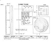
Figure 2 Illustration of vertical and short takeoff and landing (V/STOL)<br />
aircraft developed by the McDonnell Aircraft Company in the<br />
mid-1960s.<br />
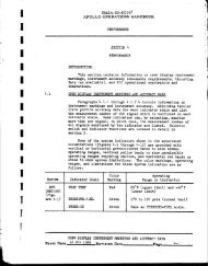
Figure 3 Hover vertical lift efficiency as a function of disc loading.<br />
Figure 4 McDonnell <strong>XV</strong>-1 compound helicopter.<br />
Figure 5 Sikorsky <strong>XV</strong>-2 convertible aircraft.<br />
Figure 6 Bell Helicopter <strong>XV</strong>-3 tilt rotor aircraft.<br />
Figure 7 Henry Berliner tilt-propeller helicopter.<br />
Figure 8 U.S. patent illustration of George Lehberger’s 1930 tilting propeller<br />
vertical takeoff “flying machine.”<br />
Figure 9 The Baynes heliplane.<br />
Figure 10 Three-view drawing of the Focke-Achgelis FA 269 convertiplane.<br />
Figure 11 Platt-LePage XR-1A lateral-twin rotor helicopter.<br />
Figure 12 Platt-LePage tilt rotor transport aircraft design.<br />
Figure 13 Illustration from the Haviland Platt patent of the tilt rotor concept.<br />
Figure 14 Transcendental Model 1-G experimental tilt rotor aircraft.<br />
Figure <strong>15</strong> Transcendental Model 2.<br />
Figure 16 York convertiplane.<br />
Figure 17 Bob Lichten (Bell), et al. in front of the <strong>XV</strong>-3.<br />
Figure 18 <strong>XV</strong>-3 at Bell, August 11, 1955.<br />
Figure 19 Crash of the <strong>XV</strong>-3 on October 25, 1956.<br />
Figure 20 Tiedown tests of the <strong>XV</strong>-3 with protective shields at Bell in<br />
July 1957.<br />
Figure 21 <strong>XV</strong>-3 in hover at Ames Research Center.<br />
xiii
xiv<br />
Figure 22 <strong>XV</strong>-3 in airplane mode of flight near Ames Research Center.<br />
Figure 23 <strong>XV</strong>-3 in the Ames Research Center 40- by 80-foot wind tunnel.<br />
Figure 24 Boeing VZ-2 tilt wing research aircraft.<br />
Figure 25 Bell 25-foot diameter proprotor on semi-span wing in the Ames<br />
Research Center 40- by 80-foot wind tunnel.<br />
Figure 26 Boeing 26-foot diameter proprotor on semi-span wing in the<br />
Ames Research Center 40- by 80-foot wind tunnel.<br />
Figure 27 The Bell stop/fold tilt rotor in the Ames Research Center 40- by<br />
80-foot wind tunnel.<br />
Figure 28 Performance tests of 5-foot diameter proprotor in the Army 7- by<br />
10-foot wind tunnel at the Ames Research Center.<br />
Figure 29 13-foot diameter proprotor in the ONERA S-1 wind tunnel, France.<br />
Figure 30 13-foot diameter proprotor in the Ames Research Center 40- by<br />
80-foot wind tunnel.<br />
Figure 31 Bell 25-foot diameter proprotor performance test in the Ames<br />
Research Center 40- by 80-foot wind tunnel.<br />
Figure 32 Members of initial Tilt Rotor Research Aircraft Project <strong>Office</strong> at<br />
Ames, 1989.<br />
Figure 33 Rotor Systems Research Aircraft (RSRA).<br />
Figure 34 Illustration from 1974 Tilt Rotor Research Aircraft Project Plan.<br />
Figure 35 Illustration of the Boeing Model 222 tilt rotor aircraft.<br />
Figure 36 1/5-scale <strong>XV</strong>-<strong>15</strong> model in 7- by 10-foot wind tunnel, (a) small<br />
landing gear housings, (b) large landing gear housings.<br />
Figure 37 Tilt Rotor Research Aircraft WBSE.<br />
Figure 38 <strong>XV</strong>-<strong>15</strong> nacelle arrangement.<br />
Figure 39 Bell test apparatus used for transmission qualification testing.<br />
Figure 40 Proprotor response to cockpit control input.
Figure 41 Simultaneous static test firing of <strong>XV</strong>-<strong>15</strong> ejection seats.<br />
Figure 42 Parachutes deployed during seat ejection test.<br />
Figure 43 Bell <strong>XV</strong>-<strong>15</strong> ground tiedown facility.<br />
Figure 44 Initial Bell tiedown tests showing metal protective shields.<br />
Figure 45 <strong>XV</strong>-<strong>15</strong> in the Ames Research Center 40- by 80-foot wind tunnel.<br />
Figure 46 Government and Bell personnel at the Dryden Flight Research<br />
Center, October 1981.<br />
Figure 47 <strong>XV</strong>-<strong>15</strong> plaque being presented to Government pilots by Bell pilots<br />
at the acceptance ceremony.<br />
Figure 48 Ames Tiedown test facility showing rescue ramp.<br />
Figure 49 Tiedown test facility at the Ames Research Center showing the<br />
hydraulic lift.<br />
Figure 50 <strong>XV</strong>-<strong>15</strong> hovering in-ground-effect during 1984 performance and<br />
downwash test.<br />
Figure 51 Method used to position the aircraft for the downwash and<br />
acoustics hover test at the Ames Research Center.<br />
Figure 52 <strong>XV</strong>-<strong>15</strong> proprotor on the propeller test apparatus at the Ames<br />
Outdoor Aerodynamic Research Facility.<br />
Figure 53 Tilt rotor structural elastic modes.<br />
Figure 54 Wing modes of the tilt rotor aircraft structure.<br />
Figure 55 <strong>XV</strong>-<strong>15</strong> during short takeoff performance test.<br />
Figure 56 Flow visualization near the <strong>XV</strong>-<strong>15</strong> wing tips.<br />
Figure 57 Flow visualization near the <strong>XV</strong>-<strong>15</strong> wing mid-span position.<br />
Figure 58 Inboard flow visualization showing “fountain flow” above the<br />
fuselage.<br />
Figure 59 Hover acoustics tests during low wind conditions at sunrise.<br />
xv
xvi<br />
Figure 60 The <strong>XV</strong>-<strong>15</strong> flying in close formation with the YO-3A for<br />
acoustics data.<br />
Figure 61 Typical cross section of the <strong>XV</strong>-<strong>15</strong> metal blades.<br />
Figure 62 <strong>XV</strong>-<strong>15</strong> Advanced Technology Blades configuration variations.<br />
Figure 63 Advanced Technology Blades proprotor mounted on the test apparatus<br />
at the Ames Research Center Outdoor Aerodynamic<br />
Research Facility.<br />
Figure 64 <strong>XV</strong>-<strong>15</strong> N702NA colocated with <strong>XV</strong>-<strong>15</strong> N703NA at the Dryden<br />
Flight Research Center, October 1981.<br />
Figure 65 The <strong>XV</strong>-<strong>15</strong> in enroute to the Paris Air Show in 1981.<br />
Figure 66 Senator Goldwater in the <strong>XV</strong>-<strong>15</strong> with Bell pilot Dorman Cannon.<br />
Figure 67 Secretary of the Navy John Lehman after flying the <strong>XV</strong>-<strong>15</strong>.<br />
Figure 68 Nap-of-the-earth flight demonstrations at Ft. Huachuca, Arizona.<br />
Figure 69 Shipboard evaluations of the <strong>XV</strong>-<strong>15</strong> onboard the USS Tripoli.<br />
Figure 70 <strong>XV</strong>-<strong>15</strong> during nap-of-the-earth flight demonstrations at<br />
Ft. Rucker, Alabama.<br />
Figure 71 <strong>XV</strong>-<strong>15</strong> at the New York Port Authority downtown heliport.<br />
Figure 72 <strong>XV</strong>-<strong>15</strong>, QSRA, and AV-8B aircraft, in formation flight at Ames<br />
Research Center.<br />
Figure 73 <strong>XV</strong>-<strong>15</strong> at the Dallas Convention Center Heliport/Vertiport.<br />
Figure 74 <strong>XV</strong>-<strong>15</strong> at the 1995 Paris Air Show with the Bell-Boeing V-22<br />
Osprey.<br />
Figure 75 The Bell-Boeing V-22 Osprey in hover flight.<br />
Figure 76 The Bell tilt rotor eagle eye unmanned aerial vehicle.<br />
Figure 77 Mockup of the BA-Model 609 civil tilt rotor aircraft with Bell-<br />
Boeing markings.<br />
Figure A-1 Transcendental Model 1-G hovering in-ground-effect.
Figure A-2 Transcendental Model 2 three-view drawing.<br />
Figure A-3 Transcendental Model 2 cutaway drawing.<br />
Figure A-4 <strong>XV</strong>-3 three-view drawing.<br />
Figure A-5 <strong>XV</strong>-3 inboard drawing, side view.<br />
Figure A-6 Three-view drawing of the <strong>XV</strong>-<strong>15</strong> tilt rotor research aircraft.<br />
Figure A-7 Conversion corridor of the <strong>XV</strong>-<strong>15</strong> tilt rotor research aircraft.<br />
Figure A-8 General layout and major components of the <strong>XV</strong>-<strong>15</strong> tilt rotor<br />
research aircraft.<br />
Figure A-9 Side view inboard profile of the <strong>XV</strong>-<strong>15</strong>.<br />
Figure A-10 Top view inboard profile of the <strong>XV</strong>-<strong>15</strong>.<br />
Figure A-11 <strong>XV</strong>-<strong>15</strong> height-velocity flight envelope.<br />
Figure A-12 <strong>XV</strong>-<strong>15</strong> variation of power with airspeed.<br />
Figure D-1 Jean Tinsley, first woman to fly the <strong>XV</strong>-<strong>15</strong> tilt rotor aircraft.<br />
Figure E-1 <strong>XV</strong>-3 at the Bell ramp, 1955.<br />
Figure E-2 Bell <strong>XV</strong>-3 personnel in front of the <strong>XV</strong>-<strong>15</strong> research aircraft.<br />
Figure E-3 <strong>XV</strong>-<strong>15</strong> flying by the Statue of Liberty.<br />
Figure E-4 <strong>XV</strong>-<strong>15</strong> flying near the Washington Monument.<br />
Figure E-5 <strong>XV</strong>-<strong>15</strong> flyby at the Jefferson Memorial.<br />
Figure E-6 <strong>XV</strong>-<strong>15</strong> landing at the Capitol Building.<br />
Figure E-7 Bell test pilots Roy Hopkins and Dorman Cannon.<br />
Figure E-8 <strong>XV</strong>-<strong>15</strong> in executive transport markings.<br />
Figure E-9 <strong>XV</strong>-<strong>15</strong> in camouflage markings.<br />
Figure E-10 <strong>XV</strong>-<strong>15</strong> in Navy gray flying along side the USS Tripoli,<br />
August 1982.<br />
xvii
xviii<br />
Figure E-11 Ken Wernicke, Bell tilt rotor design engineer, 1965.<br />
Figure E-12 Ken Wernicke after flying the <strong>XV</strong>-<strong>15</strong>.<br />
Figure E-13 <strong>XV</strong>-<strong>15</strong> N703NA crew station (1982).<br />
Figure E-14 Composite photograph showing V-22 Osprey in hover, conversion,<br />
and airplane modes of flight.
List of Acronyms<br />
AARL Army Aeronautical Research Laboratory<br />
AATD Army Aeronautical Test Directorate<br />
ADTA Aviation Development Test Activity<br />
AEFA Army Engineering and Flight Activity<br />
AFAPL Air Force Aero Propulsion Laboratory<br />
AFSRB Airworthiness and Flight Safety Review Board<br />
AGARD Advisory Group for Aerospace Research and Development,<br />
North Atlantic Treaty Organization<br />
AHS American Helicopter Society<br />
AIAA American Institute of Aeronautics and Astronautics<br />
AMRDL Army Air Mobility Research and Development Laboratory<br />
APA Airport Planners Association<br />
ARC Ames Research Center<br />
ASME American Society of Mechanical Engineers<br />
ASRO Advanced Systems Research <strong>Office</strong><br />
ASW Anti-Submarine Warfare<br />
ATB Advanced Technology Blade<br />
ATM Air Traffic Management<br />
ATTT Advanced Tiltrotor Transport Technology<br />
BHTI Bell Helicopter Textron Inc.<br />
CAP Composite Aircraft Program<br />
CNO Chief of Naval Operations<br />
COD Carrier Onboard Delivery<br />
CPIF Cost Plus Incentive Fee<br />
CTR Civil Tilt Rotor<br />
CTRDAC Civil Tiltrotor Development Advisory Committee<br />
DCAA Defense Contract Audit Agency<br />
DFRC Dryden Flight Research Center<br />
DOD Department of Defense<br />
DOT Department of Transportation<br />
ECGB Engine Coupling Gearbox<br />
EMD Engineering Manufacturing Development<br />
EMI Electromagnetic Interference<br />
EUROFAR European Future Advanced Rotorcraft<br />
FAA Federal Aviation Administration<br />
FAI Federation Aeronautique Internationale<br />
FFS Force Feel System<br />
FSAA Flight Simulator for Advanced Aircraft<br />
FSD Full Scale Development<br />
GPS Global Positioning System<br />
HAI Helicopter Association International<br />
HUM Health and Usage Monitoring<br />
IAS Institute of Aeronautical Sciences<br />
IGE In-ground-effect<br />
IOC Initial Operating Capability<br />
IR&D Independent Research and Development<br />
xix
xx<br />
JAA Joint Aviation Authorities<br />
JARG Joint Aeronautical Research Group<br />
JTAG Joint Technology Assessment Group<br />
JTR Joint Transport Rotorcraft<br />
JVX Joint Vertical Experimental<br />
LaRC Langley Research Center<br />
LHX Light Helicopter Experimental<br />
LPH Amphibious Assault Ship (helicopters)<br />
MAC Military Airlift Command<br />
MCAS Marine Corps Air Station<br />
NACA National Advisory Committee for Aeronautics<br />
NALF Naval Auxiliary Landing Field<br />
NAS National Aerodynamic Simulation<br />
NASA National Aeronautics and Space Administration<br />
NATC Naval Air Test Center<br />
NATO North Atlantic Treaty Organization<br />
NAVAIR Naval Air Systems Command<br />
NAVMAT Naval Materiel Command<br />
NOE Nap-of-the-earth<br />
NRTC National Rotorcraft Technology Center<br />
NTSB National Transportation Safety Board<br />
OARF Outdoor Aerodynamic Research Facility<br />
OART <strong>Office</strong> of Aeronautical Research and Technology<br />
OEI One engine inoperative<br />
OGE Out-of-ground-effect<br />
ONERA <strong>Office</strong> National d’Etudes et de Recherches Aerospatiales<br />
PCM Pulse Code Modulation<br />
QSRA Quiet Short-Haul Research Aircraft<br />
R&QA Reliability and Quality Assurance<br />
RFP Request for Proposal<br />
RMDU Remote Multiplex/Digitizer Unit<br />
RPV Remotely Piloted Vehicle<br />
RSRA Rotor Systems Research Aircraft<br />
SAE Society of Automotive Engineers<br />
SAR Search and Rescue<br />
SAWE Society of Allied Weight Engineers<br />
SBA-MS Sea Based Air-Master Study<br />
SCAS Stability and Control Augmentation System<br />
SCS Sea Control Ship<br />
SEB Source Evaluation Board<br />
SETP Society of Experimental Test Pilots<br />
SHCT Short-Haul Civil Tiltrotor<br />
SNI Simultaneous non-Interfering<br />
STO Short Takeoff<br />
STOL Short Takeoff and Landing<br />
TDT Transonic Dynamics Tunnel
TRENDS Tilt Rotor Engineering Database System<br />
TRRA Tilt Rotor Research Aircraft<br />
UAV Unmanned Aerial Vehicle<br />
UT University of Texas<br />
VDTR Variable Diameter Tilt Rotor<br />
V/STOL Vertical or Short Takeoff and Landing<br />
VDTR Variable Diameter Tilt Rotor<br />
VMS Vertical Motion Simulator<br />
VTOL Vertical Takeoff and Landing<br />
WBSE Work Breakdown Structure Elements<br />
WPAFB Wright-Patterson Air Force Base<br />
xxi
Introduction<br />
For as long as can be remembered,<br />
humans have always wanted to fly… to<br />
be able to soar into the sky and alight<br />
wherever their fancy takes them. One<br />
such individual was Leonardo da Vinci<br />
(1452-<strong>15</strong>19), who was the first person<br />
to approach heavier-than-air-flight in a<br />
somewhat scientific manner. Da Vinci<br />
is credited with the design of the first<br />
helicopter, basically a helical air screw<br />
(figure 1), which was conceived to lift<br />
off the ground vertically—no ground<br />
roll required, no runway needed.<br />
However, nearly four centuries later,<br />
when technology advancements<br />
allowed sustained, powered manned<br />
flight, the practical solution demonstrated<br />
by the Wright brothers used a<br />
fixed-surface to provide the lift. This required the aircraft to accelerate along the<br />
ground until a sufficient speed was reached so that the necessary force could be<br />
generated for the vehicle to become airborne. The da Vinci dream of vertical<br />
liftoff was finally achieved with the development of the successful helicopter<br />
more than 30 years after the first fixed-wing flight. 1 While, in the second half of<br />
this century, this remarkable machine has become an essential vehicle for numerous<br />
civil and military applications, because of its vertical lift capabilities, it<br />
remains extremely limited in the speed and range that it can attain. By the middle<br />
of this century, these limitations to the helicopter’s effectiveness and the demonstrated<br />
capabilities of the fixed-wing airplane had fostered a new dream… the<br />
development of an aircraft with the vertical takeoff and hover capability of the<br />
helicopter, and with the speed and range of the fixed-wing aircraft. This is the<br />
story of the quest for a new type of aircraft that would make that dream a reality.<br />
The search for an aircraft type with Vertical Takeoff and Landing (VTOL) capabilities<br />
triggered the imagination of designers and inventors to produce numerous<br />
configurations using a wide variety of lifting and propulsion devices. A summary<br />
of these configurations is shown in the V/STOL (Vertical or Short Takeoff and<br />
Landing) concepts illustration 2 prepared by the McDonnell Aircraft Company in<br />
the 1960s (figure 2). For the various aircraft types considered, one of the key distinguishing<br />
features is associated with the device used for providing the vertical<br />
1 th While several helicopters became airborne during the first three decades of the 20 century, the<br />
Focke-Wulf Fw-61 is generally credited with being the first helicopter to demonstrate performance<br />
and precision control, essential characteristics of a successful helicopter. The first flight<br />
occurred in Germany in 1937 and public flight demonstrations were made in 1938.<br />
2 Seth B. Anderson, “Historic Overview of V/STOL Aircraft Technology,” NASA TM 81280,<br />
March 1981.<br />
Figure 1.<br />
Leonardo da Vinci <strong>15</strong> th<br />
century helical air screw<br />
flying machine.<br />
1
Figure 2.<br />
Illustration of vertical and<br />
short takeoff and landing<br />
(V/STOL) aircraft developed<br />
by the McDonnell Aircraft<br />
Company in the mid-1960s.<br />
2<br />
13<br />
12<br />
11<br />
10<br />
14<br />
9<br />
8<br />
<strong>15</strong><br />
HUGHES STOPPED<br />
ROTOR<br />
McDONNELL<br />
MODEL 177<br />
EWR/REPUBLIC<br />
US/FRG<br />
DORNIER<br />
De 31<br />
GERMAN<br />
VJ-101 C<br />
McDONNELL<br />
BRITISH<br />
P-148<br />
<strong>XV</strong>-1<br />
FAIREY<br />
ROTODYNE-Y<br />
VFW VAK-191B<br />
7<br />
16<br />
6<br />
17<br />
FRENCH<br />
VTOL MIRAGE III-V<br />
5<br />
19<br />
18<br />
LOCKHEED<br />
<strong>XV</strong>-4A<br />
SHORT<br />
4<br />
"TRANSONIC"<br />
SC.1<br />
MILLER<br />
LOCKHEED<br />
VTOL-F-104<br />
3<br />
SHORT<br />
Revised: September 1967<br />
20<br />
SIKORSKY<br />
S-57(<strong>XV</strong>-2)<br />
LIFT<br />
PD 49<br />
BRITISH<br />
FLYING PROTOTYPE<br />
TRANSPORT<br />
N.A.A.<br />
VTOL-P.D. 16<br />
LOCKHEED<br />
UNDER CONSTRUCTION WIND<br />
TUNNEL TESTS OR MOCK UP<br />
2<br />
21<br />
DESIGN CONCEPT STUDY<br />
G.E.-RYAN<br />
<strong>XV</strong>-5A<br />
HOVER<br />
1<br />
<strong>XV</strong>-4B<br />
TIP<br />
22<br />
FOR<br />
JET<br />
TRANSPORT<br />
ENGINES TIP JETS STATIC<br />
FIAT<br />
G 95-4<br />
A<br />
LIFT+LIFT/CRUISE<br />
McDONNELL<br />
COMBINED POWER<br />
23<br />
TRANSPORT<br />
POWER PLANT<br />
FLYING<br />
FLYING SAUCERS<br />
(AVRO-CANADA)<br />
B<br />
BOEING<br />
FAN<br />
TIP TURBINE<br />
24<br />
FIGHTER<br />
PNEUMATIC<br />
PLANT FOR<br />
DRIVE<br />
HOVER<br />
PLATFORMS<br />
FLYING JEEPS<br />
McDONNELL<br />
OMNIPLANE<br />
VANGUARD-2C<br />
HOOP<br />
V/STOL<br />
AIRCRAFT<br />
SUMMARY<br />
McDONNELL<br />
AIRCRAFT<br />
SURVEY<br />
ONE-MAN-LIFTS<br />
(RUSSIAN)<br />
LOCKHEED<br />
AUGMENTED POWER<br />
C<br />
MECH<br />
FAN<br />
25<br />
GROUND EFFECT<br />
MACHINES<br />
26<br />
PLANT FOR HOVER<br />
SEPARATE TYPES<br />
D<br />
SPECIAL<br />
AND<br />
E<br />
TAIL-SITTERS<br />
27 28<br />
29<br />
30<br />
31<br />
32<br />
33<br />
34<br />
AAFSS<br />
ROTOR<br />
LOCKHEED<br />
SHAFT DRIVE<br />
DYNAMIC<br />
HELICOPTERS<br />
F<br />
STOL AIRCRAFT<br />
FOR HOVER & FORWARD FLIGHT<br />
McDONNELL 188<br />
BREGUET 941)<br />
PIASECKI<br />
STOWED ROTOR<br />
MASS<br />
FLOW<br />
FIAT<br />
G<br />
G 95-4<br />
COMPOUND<br />
X-14<br />
SIKORSKY<br />
STOWED ROTOR<br />
BELL<br />
HAWKER P-1127<br />
<strong>XV</strong>-6A<br />
BELL <strong>XV</strong>-3<br />
FIXED POWER PLANT<br />
FLOW GENERATION<br />
SAME PROPULSION SYSTEM<br />
DEFLECTOR<br />
EXH.<br />
H<br />
PROP<br />
ROTOR<br />
TILTABLE MASS<br />
MASS FLOW<br />
EXHAUST<br />
ONLY<br />
GENERATOR<br />
AND DEFLECTOR<br />
DUCTED<br />
AND<br />
SLIP<br />
BLEED<br />
CURTISS WRIGHT<br />
lift. If the thrust for vertical takeoff is produced over a small area, such as the<br />
exhaust nozzle area of a “direct-lift” jet engine, the lifting device is referred to as<br />
a “high disc loading” type (where disc loading is defined as the thrust divided by<br />
the area over which it is produced). On the other end of the spectrum, if a large<br />
area is used to generate the vertical lift, as in the case of a helicopter with its<br />
large diameter rotors, the system is called a “low disc loading” device. This singular<br />
parameter (disc loading) is a direct indicator of the achievable level of efficiency<br />
in the production of the required hover thrust, as shown in figure 3. Low<br />
FREE<br />
X-19<br />
PROPELLER<br />
STREAM<br />
MIKOYAN V/STOL<br />
X-100<br />
CURTISS WRIGHT<br />
PLANT<br />
FAN PROP<br />
CURTISS WRIGHT<br />
TILT POWER<br />
SLIPSTREAM<br />
300<br />
VZ-2<br />
BOEING VERTOL-76<br />
COLLINS<br />
AERODYNE<br />
CHANCE-VOUGHT<br />
ADAM<br />
FAN<br />
PROPELLER<br />
BOEING VERTOL<br />
NORD-CADET<br />
500<br />
BELL<br />
X-22A<br />
DOUGLAS-DOAK<br />
X-16<br />
VOUGHT-RYAN<br />
HILLER XC-142<br />
HILLER<br />
X-18<br />
FAIRCHILD 224<br />
VZ-5FZ<br />
LOCKHEED<br />
CL-379<br />
ROBERTSON<br />
VTOL<br />
RYAN-02<br />
VZ3-RY<br />
35<br />
36<br />
CANADAIR CL-84<br />
VFW VC-400<br />
48<br />
49<br />
50<br />
51<br />
52<br />
47<br />
46<br />
37<br />
45<br />
38<br />
39<br />
40<br />
41<br />
42<br />
43<br />
44
disc loading lifting systems are capable<br />
of delivering significantly more<br />
thrust per horsepower than higher disc<br />
loading devices. Therefore, for applications<br />
where extended-duration hover<br />
or near-hover conditions are required,<br />
or where lower installed power or<br />
lower fuel consumption in hover is<br />
important, low disc loading aircraft<br />
concepts appear to be the right choice.<br />
The vertical lift efficiency of a VTOL<br />
aircraft, however, is not the only area<br />
of interest in the selection of a configuration.<br />
In addition to the need for<br />
vertical liftoff, these aircraft need to be<br />
designed to perform a cruise mission,<br />
usually with certain speed and range<br />
requirements. Performance in the<br />
cruise flight regime, therefore, needs<br />
to be assessed for each VTOL configuration.<br />
The challenge of finding an aircraft type that meets both the hover- and<br />
cruise-mode performance criteria, while also meeting other operational, economic,<br />
and environmental requirements was the major task encountered by the developers<br />
of VTOL technology.<br />
Figure 3.<br />
Hover vertical lift efficiency<br />
as a function of disc loading.<br />
3
Figure 4.<br />
McDonnell <strong>XV</strong>-1<br />
compound helicopter.<br />
(Boeing Photograph<br />
AD98-0209-13)<br />
Figure 5.<br />
Sikorsky <strong>XV</strong>-2<br />
Convertible Aircraft.<br />
4<br />
Early Efforts<br />
For one group of military planners in the late 1940s and early 1950s, the mission<br />
requirements included significant hover duration, low speed maneuvering and<br />
agility, and a speed and range greater than current helicopter capabilities. This, and<br />
additional mission factors such as the need for moderate downwash velocities<br />
below the hovering aircraft to enable safe rescue operations, led the planners to<br />
specify low disc loading for the new VTOL vehicle. These considerations resulted<br />
in the August 1950 initiation of the joint U.S. Army and U.S. Air Force<br />
Convertiplane Program. This program was formulated to provide demonstrations<br />
of different approaches to meeting the convertiplane requirements. The aircraft<br />
selected from the design competition were the <strong>XV</strong>-1 compound helicopter, figure 4<br />
(proposed by the McDonnell Aircraft Co.), the <strong>XV</strong>-2 stoppable rotor aircraft, figure<br />
5 (proposed by Sikorsky Aircraft), and the <strong>XV</strong>-3 tilt rotor aircraft, figure 6 (submitted<br />
by the Bell Helicopter Company). A discussion of the aircraft concepts<br />
addressed in the Convertiplane Program is provided by R. W. Prouty’s February<br />
1984 Rotor and Wing International article “From <strong>XV</strong>-1 to JVX—A Chronicle of<br />
the Coveted Convertiplane.”<br />
Two designs, the <strong>XV</strong>-1 and the <strong>XV</strong>-3, survived the initial evaluation phase and<br />
were developed as test aircraft for limited flight evaluations. While the <strong>XV</strong>-1
achieved a speed of 200 mph in 1955<br />
(as the <strong>XV</strong>-3 was encountering technical<br />
problems, to be discussed later), it<br />
became apparent that the compound<br />
helicopter, in high speed flight, would<br />
still experience the type of severe<br />
oscillatory load conditions that limits<br />
the speed capability of the conventional<br />
helicopter. These vibrations are due<br />
to the edgewise movement of the rotor<br />
through the air during cruise flight.<br />
Helicopter rotors operating in the<br />
cruise mode are burdened with the<br />
tasks of producing the required thrust<br />
and lift while delivering the forces and<br />
moments to maintain a balanced, or<br />
trimmed, flight state. Because of the<br />
essentially edgewise motion of the<br />
rotor, the blades experience an aerodynamic acceleration and deceleration as they<br />
“advance” into and “retreat” from the airstream. Although the compound helicopter<br />
uses a conventional fixed-wing to produce the required lift while in the cruise<br />
flight mode, thereby unloading the rotor from the burden of producing lift and<br />
trim moments, it still encounters the variations in rotor blade drag due to the<br />
advancing and retreating airloads during each rotation. In addition, the edgewise<br />
rotor limits maneuver capability at high speeds because of the extreme load oscillations<br />
that occur on the rotor. Also, the exposed rotor hub and control hardware<br />
contribute significantly to drag in the high speed cruise mode, further limiting<br />
maximum airspeed. The compound helicopter also suffered the weight penalty of<br />
carrying the additional cruise mode propulsion system hardware. Collectively,<br />
these issues inhibit the performance potential of the compound helicopter. The<br />
compound helicopter was not the answer to the search for a viable low disc loading<br />
VTOL high performance aircraft.<br />
According to advocates during the 1950s, the tilt rotor configuration was projected<br />
to have the potential to overcome many of the limitations or deficiencies of the helicopter<br />
and compound helicopter. The <strong>XV</strong>-3 provided an opportunity to demonstrate<br />
the effectiveness of the tilt rotor aircraft and learn about unknown problems<br />
of this aircraft type. However, before the story of the <strong>XV</strong>-3 program is told, the<br />
evolution and early history of the tilt rotor aircraft will be briefly reviewed.<br />
During the 1920s and 1930s, the numerous innovative flying machines devised<br />
included several concepts that were expected to provide vertical takeoff capabilities.<br />
One of these was developed in the U.S. by Henry Berliner 3 in the early<br />
3 Jay P. Spenser, Whirlybirds, A <strong>History</strong> of U.S. Helicopter Pioneers, University of Washington<br />
Press, 1998.<br />
Figure 6.<br />
Bell helicopter <strong>XV</strong>-3<br />
tilt rotor aircraft.<br />
(Bell Photograph 209854)<br />
5
Figure 7.<br />
Henry Berliner tiltpropeller<br />
helicopter.<br />
(National Air and Space<br />
Museum–NASM–Photo)<br />
6<br />
1920s (figure 7). This design resembled<br />
a fixed-wing biplane of the period,<br />
except that it had a large diameter<br />
fixed-pitch propeller mounted on a<br />
vertical shaft near the tip of each<br />
wing. For forward flight, the shafts<br />
would be tilted forward. Reports indicate<br />
that the Berliner helicopter<br />
achieved forward speeds of about 40<br />
mph. While the propellers were not<br />
designed to convert fully to the conventional<br />
airplane mode, the Berliner<br />
side-by-side helicopter was an early<br />
example of the rotor arrangement used<br />
on current tilt rotor aircraft.<br />
Another design conceived to provide vertical lift and forward flight is the “Flying<br />
Machine” for which George Lehberger was issued a patent in September 1930<br />
(figure 8). His approach contained the basic concept of the tilt rotor aircraft, that<br />
is, the use of a relatively low disc loading thruster (propeller) that can tilt its axis<br />
from the vertical (for vertical lift) to the horizontal (for propulsive thrust). While<br />
the authors are not aware of any attempt by inventor George Lehberger to develop<br />
this vehicle, it would be expected to encounter performance, loads, structural<br />
dynamics, and control deficiencies if built as indicated in the patent illustration.<br />
The vectored thrust low disc loading VTOL aircraft required many technology<br />
advancements before it would be a practical aircraft type.<br />
In the late 1930s, a British patent was issued for the Baynes Heliplane (figure 9)<br />
which resembled the configuration of the current tilt rotor aircraft. Inadequate<br />
financial backing prevented development work, leaving the exploration of tilt<br />
rotor technology to other engineers in the four decades that followed.<br />
In Germany, the Focke-Achgelis FA-269 trail-rotor convertiplane project was initiated<br />
in 1942. This aircraft, illustrated in figure 10, followed the moderately successful<br />
lateral twin-rotor helicopter, the Focke-Wulf Fw-61 flown in 1937. The<br />
FA-269 used pusher propellers that tilted below the wing for takeoff. This project<br />
was discontinued after a full-scale mockup was destroyed during a bombing in<br />
WWII. Years later, variants of the trail-rotor tilt rotor configuration would surface<br />
again in design studies at Bell and McDonnell Douglas.<br />
The accomplishments of the German Focke-Wulf activities did not go unnoticed by<br />
the americans. Two enterprising engineers, Dr. Wynn Laurence LePage and Haviland<br />
Hull Platt of the Platt-LePage Aircraft Company of Eddystone, Pennsylvania,<br />
became intrigued with the success of the German helicopter and decided to pursue<br />
the development of a viable helicopter in the U.S. with the same general arrangement<br />
of the Fw-61. The product of this work was the 1941 Platt-LePage XR-1A lateral
Figure 8. U.S. patent illustration of George Lehberger’s 1930 tilting propeller vertical takeoff “flying machine.”<br />
7
Top:<br />
Figure 9.<br />
The Baynes Heliplane.<br />
Bottom:<br />
Figure 10.<br />
Three-view drawing of<br />
the Focke-Achgelis<br />
FA-269 convertiplane.<br />
8<br />
twin-rotor helicopter (figure 11). This<br />
aircraft inspired the design of a large<br />
(53,000-lb.) tilt rotor aircraft (figure 12),<br />
which resembled the XR-1A configuration,<br />
but incorporated mechanisms that<br />
permitted the rotors to be tilted for forward<br />
flight. While Platt-LePage never<br />
developed their tilt rotor design,<br />
Haviland Platt applied for a patent for<br />
the concept on July 7, 1950, and was<br />
granted U. S. patent 2,702,168 on<br />
February <strong>15</strong>, 1955 (figure 13).<br />
The next significant appearance of the<br />
tilt rotor occurred in early 1947 when<br />
the Transcendental Aircraft Corporation<br />
of New Castle, Delaware, initiated work<br />
that led to the development of the Model<br />
1-G tilt rotor aircraft (figure 14). The<br />
founding principals of Transcendental<br />
were Mario A. Guerrieri and Robert<br />
(Bob) L. Lichten, who had been<br />
coworkers at the Kellett Aircraft<br />
Company. Bob Lichten had earlier<br />
worked for pioneer helicopter designers<br />
LePage and Platt and had become<br />
intrigued with the tilt rotor concept. His<br />
experience at Platt-LePage provided him<br />
a mission that he pursued for the rest of<br />
his life.<br />
While at Kellett, Guerrieri and Lichten<br />
investigated the performance of a helicopter<br />
rotor acting as a propeller and, encouraged by the results, decided to<br />
demonstrate tilt rotor technology by independently building and flying a small,<br />
single-place experimental aircraft. Appendix A contains a brief description and<br />
the general characteristics of this aircraft, the Transcendental Model 1-G.<br />
Lichten left Transcendental in 1948, and, in September 1952, Guerrieri sold his<br />
interests in the company to William E. Cobey, a Kellett Aircraft Corporation<br />
vibrations expert who continued the development of the Model 1-G. With some<br />
funding provided by a 1952 Army/Air Force contract for flight data reports and<br />
analyses, hover testing of the 1750 lb. Model 1-G began on June <strong>15</strong>, 1954.<br />
The Transcendental Model 1-G, however, met an unfortunate end. After successfully<br />
completing more than 100 flights in a period of just over one year, includ-
ing partial conversions to within 10 degrees of the airplane mode, an inadvertent<br />
reduction of the rotor collective pitch while flying with the rotors tilted forward<br />
led to a crash into the Chesapeake Bay on July 20, 1955. Although the aircraft<br />
was destroyed, the crash occurred near land in shallow water, which allowed the<br />
pilot, who sustained minor injuries, to wade ashore. 4<br />
4 This description of the Transcendental Model 1-G accident was based on an account by Mario<br />
Guerrieri (Letters to the Editor, Vertiflite, Vol. 34, Number 5, Sept./Oct. 1988) in which he relates<br />
information provided to him by William Cobey. This information disputes the account noted by<br />
Mark and Lynn in “Aircraft Without Airports—Changing the Way Men Fly” (Vertiflite, May/June<br />
1988) that states that the accident was fatal to the pilot.<br />
Figure 11.<br />
Platt LePage XR-1A lateral<br />
twin-rotor helicopter.<br />
(Photograph courtesy of<br />
Jay Hendrickson)<br />
Figure 12.<br />
Platt LePage tilt rotor transport<br />
aircraft design<br />
(Boeing print-Ames<br />
AD98-0209-22)<br />
9
Figure 13. Illustration from the Haviland Platt patent of the tilt rotor concept.<br />
10<br />
United States Patent <strong>Office</strong><br />
2,702,168<br />
CONVERTIBLE AIRCRAFT<br />
Haviland H. Platt, New York, N. Y.<br />
Application July 7, 1950, Serial No. 172,507<br />
<strong>15</strong> Claims. (Cl. 244--7)<br />
2,702,168<br />
Patented Feb. <strong>15</strong>, 1955
A second, improved, Transcendental<br />
tilt rotor aircraft, the 2,249 lb., twoplace<br />
Model 2 (figure <strong>15</strong>), was subsequently<br />
developed by Cobey but funding<br />
limitations resulting from the withdrawal<br />
of Air Force support prevented<br />
the expansion of the flight envelope,<br />
and the program was terminated in<br />
1957. Transcendental became associated<br />
with the short-lived Helicopter<br />
Division of the Republic Aviation<br />
Corporation, Farmingdale, Long<br />
Island, but the failure to gain<br />
Government interest ended the venture.<br />
The Transcendental Model 2 is<br />
described in Appendix A.While never<br />
attaining flight in the airplane mode<br />
(but having flown within 10 degrees of<br />
airplane mode), the Model 1-G is generally<br />
recognized as the first vehicle to<br />
successfully explore the conversion<br />
mode of flight of the tilt rotor aircraft.<br />
Other tilt rotor aircraft designs<br />
appeared during the 1950s but most<br />
never left the drawing board. One aircraft,<br />
the York convertiplane (figure<br />
16) was developed by C. H. York in<br />
1956. However, no record of its operational<br />
experience was found.<br />
Figure 14. Transcendental Model 1-G experimental tilt rotor aircraft.<br />
(Photograph courtesy of John Schneider)<br />
Figure <strong>15</strong>. Transcendental Model 2. (John Schneider-Ames Photograph AD98-0209-19)<br />
Figure 16. York convertiplane. (John Schneider-Ames Photograph AD98-0209-16)<br />
11
Figure 17.<br />
Bob Lichten, extreme left,<br />
et al. in front of the <strong>XV</strong>-3.<br />
(Bell Photograph 214838)<br />
Figure 18.<br />
<strong>XV</strong>-3 at Bell,<br />
August 11, 1955.<br />
(Bell Photograph 210021)<br />
12<br />
<strong>XV</strong>-3 Program<br />
Long before Transcendental initiated<br />
flight tests of the Model 1-G, Bob<br />
Lichten had joined Bell Aircraft where<br />
he was given the opportunity to further<br />
the advancement of the tilt rotor with<br />
the research and development resources<br />
of a major rotorcraft company. At Bell,<br />
Lichten began the task of developing a<br />
new technology base associated with<br />
the tilt rotor aircraft. In 1951, in<br />
response to the Convertible Aircraft<br />
Program Request For Proposal (RFP)<br />
for the design of a “convertiplane,” the<br />
Bell proposal offered Lichten’s tilt<br />
rotor, the Bell Model 200. With the<br />
subsequent award of a contract for two<br />
full-scale “tilting-thrust-vector convertiplanes”<br />
in October 1953, and the infusion<br />
of Army and Air Force funds, the<br />
exploration of this new technology was accelerated. The Bell Model 200, designated<br />
the <strong>XV</strong>-3 5 by the Army and Air Force, produced some interesting technical challenges<br />
for Lichten and his team during the next thirteen years. Figure 17 shows<br />
Bob Lichten, the principal advocate of the tilt rotor concept, standing in front of<br />
his creation, the <strong>XV</strong>-3.<br />
Instability<br />
Following an extensive series of ground<br />
tests by Bell, the initial hover trial of<br />
the <strong>XV</strong>-3 was flown on August 11,<br />
1955 (figure 18). After noting satisfactory<br />
characteristics during the beginning<br />
of the flight, Bell test pilot Floyd<br />
Carlson experienced a high vibration in<br />
hover. During a subsequent flight on<br />
August 18, 1955, a reappearance of the<br />
rotor dynamic instability problem<br />
resulted in a hard landing that caused<br />
minor airframe damage. A thorough<br />
ground investigation was conducted to<br />
5 Interesting summaries of the early years of Bell’s development of tilt rotor technology are provided<br />
in Aerophile, Volume 2, Number 1, June 1979; “The Rebirth of the Tiltrotor - The 1992<br />
Alexander A. Nikolsky Lecture” by Robert Lynn (Journal of the American Helicopter Society,<br />
Vol. 38, No. 1, Jan. 1993); and “Aircraft Without Airports - Changing the Way Men Fly” by Hans<br />
Mark and Robert Lynn (Vertiflite, May/June 1988).
understand and resolve the cause of the<br />
dynamic instability. Flight testing<br />
resumed on March 29, 1956, but on<br />
July 25 the instability occurred again,<br />
causing Bell to conduct another series<br />
of ground tiedown tests which lasted<br />
until late September of that year.<br />
It is important to note that the ability of<br />
the rotorcraft dynamicists of that period<br />
to analyze complex systems (such as<br />
the rotor/pylon/wing of the tilt rotor)<br />
was quite primitive compared to the<br />
computational capabilities of the 1990s.<br />
The attempts to correct the instability<br />
that occurred on the <strong>XV</strong>-3 had to be done by combining the available analytical<br />
methods with experimental data. Therefore, ground tiedown tests were needed to<br />
expand the database documenting the fundamental characteristics of the tilt rotor as<br />
well as to evaluate configuration changes.<br />
Following the second ground test effort, flight testing continued with the goal of<br />
expanding the speed and conversion envelope of the <strong>XV</strong>-3. On October 25, 1956, as<br />
Bell test pilot Dick Stansbury moved the rotor shaft 17 degrees forward from the vertical,<br />
a severe rotor instability occurred that resulted in extremely high cockpit vibrations<br />
and caused the pilot to black out. The subsequent loss of control caused the number 1<br />
<strong>XV</strong>-3 ( aircraft tail number 4147) to crash, seriously injuring the pilot (figure 19).<br />
The <strong>XV</strong>-3 program faced a crisis. The inability to solve the instability using<br />
traditional analyses, experimentation, and trial-and-error empirical methods<br />
made even some of the tilt rotor’s most avid supporters question the readiness<br />
of this technology. But the believers held on. A satisfactory solution to the<br />
rotor/pylon/wing dynamic instability problem had to be found. Advocates of<br />
the tilt rotor at Bell and the Government decided to continue the work and<br />
authorized the initiation of a major design change as well as plans for testing<br />
the <strong>XV</strong>-3 in the NACA Ames Aeronautical Laboratory 6 40- by 80-foot wind<br />
tunnel. The original three-bladed, 25-ft diameter articulated rotor was<br />
replaced with a two-bladed stiff-inplane rotor. By July 18, 1957, with isolated<br />
two-bladed rotor static tests and rotors-installed <strong>XV</strong>-3 tiedown tests completed<br />
(figure 20), investigations of the performance and dynamic behavior of the<br />
modified <strong>XV</strong>-3 began.<br />
6 The NACA (National Advisory Committee for Aeronautics) was the predecessor to the NASA<br />
(National Aeronautics and Space Administration). The NACA became the NASA in October<br />
1958 and the Ames Aeronautical Laboratory was renamed the Ames Research Center (ARC).<br />
ARC is located at Moffett Federal Airfield, formerly Moffett Naval Air Station, about 40 miles<br />
south of San Francisco, California.<br />
Figure 19.<br />
Crash of the <strong>XV</strong>-3 on<br />
October 25, 1956.<br />
(Bell Photograph 217259)<br />
13
Figure 20.<br />
Tiedown tests of the <strong>XV</strong>-3<br />
with protective shields at<br />
Bell in July, 1957.<br />
(Bell Photograph 220955)<br />
Figure 21.<br />
<strong>XV</strong>-3 in hover at<br />
Ames Research Center.<br />
(Bell Photograph 228649)<br />
14<br />
In the following 18 months, the <strong>XV</strong>-3<br />
(tail number 4148) with its new rotor<br />
system underwent two wind tunnel<br />
entries in the 40- by 80-foot wind tunnel<br />
(September-October 1957 and<br />
October 1958) and an additional series<br />
of ground tiedown and flight tests.<br />
During this period further changes<br />
were made to improve stability,<br />
including the reduction of the rotor<br />
diameter to 23 feet, the addition of<br />
external struts to stiffen the wing, and<br />
a significant increase in the stiffness of<br />
the rotor controls. The configuration<br />
that emerged accomplished the elusive<br />
goal of completing a dynamically stable full conversion to the airplane mode.<br />
This occurred at Bell on December 18, 1958, with test pilot Bill Quinlan at the<br />
controls. Subsequent flights explored the effect of wing stiffness (by modifying<br />
the strut attachments) and expanded the flight envelope within the fairly narrow<br />
range of the <strong>XV</strong>-3’s performance capabilities.<br />
Government Flight Tests<br />
The <strong>XV</strong>-3 was transported to Edwards Air Force Base where, from May through<br />
July 1959, Air Force Major Robert Ferry conducted a Government flight evaluation.<br />
The tests included handling qualities<br />
assessments, Short Takeoff and<br />
Landing (STOL) operations, and<br />
autorotation demonstrations. The Air<br />
Force test report, 7 authored by Project<br />
Engineer Lt. Wallace H. (Wally)<br />
Deckert, USAF, and Major Ferry,<br />
noted numerous deficiencies in the<br />
performance and flying qualities of the<br />
aircraft. However, in spite of the deficiencies,<br />
the report concluded that “the<br />
fixed-wing prop-rotor (i.e. the tilt<br />
rotor) principle is feasible and should<br />
be given serious consideration in<br />
future Vertical or Short Takeoff and<br />
Landing (V/STOL) aircraft design<br />
competition.” “The <strong>XV</strong>-3 demonstrated<br />
that the fixed-wing prop-rotor con-<br />
7 W. H. Deckert, R. G. Ferry, “Limited Flight Evaluation of the <strong>XV</strong>-3 Aircraft,” TR-60-4 ARDC<br />
<strong>XV</strong>-3, May 1960.
cept is operationally practical with<br />
safety and complexity comparable to<br />
helicopters.”<br />
After the conclusion of the flight program<br />
at Edwards AFB, the <strong>XV</strong>-3 was<br />
transported to NASA ARC onboard an<br />
Air Force C-130, where flight testing<br />
continued until July 1962 (figure 21).<br />
The first full tilt rotor conversion at<br />
Ames was performed by test pilot Fred<br />
Drinkwater on August 12, 1959 (figure<br />
22). This flight program was followed<br />
by an additional entry in the Ames 40by<br />
80-foot wind tunnel (in June-July<br />
1962, figure 23) to investigate the<br />
effects of changes to the pitch-flap<br />
coupling on rotor flapping and highspeed<br />
airplane mode stability.<br />
Pitch-flap coupling refers to a feature<br />
provided by the hub design wherein<br />
the blade pitch angle is changed in a<br />
manner that alters the amount of outof-plane<br />
flapping motion that occurs.<br />
A standard stabilizing pitch-flap coupling,<br />
referred to as δ 3 ,reduces the<br />
flapping displacement by reducing<br />
the pitch angle as flapping increases.<br />
After another modification (this time<br />
to increase the pylon/wing stiffness)<br />
the <strong>XV</strong>-3 was able to reach a speed<br />
of <strong>15</strong>5 knots before indications of<br />
low damping, i.e. aeroelastic instability,<br />
were seen. While this was a definite<br />
improvement over the earlier stability limits of the <strong>XV</strong>-3, it would still be<br />
inadequate for the intended military mission application of the tilt rotor aircraft<br />
and was substantially below the predicted performance capability of this<br />
aircraft type.<br />
Stability Validation<br />
In 1965, after a period of model-scale testing and analytical studies, Bell funded<br />
a ground test to continue its investigation of <strong>XV</strong>-3 tilt rotor dynamics. To further<br />
pursue this work in a full-scale wind tunnel test, Robert (Bob) Lynn, Bell’s Chief<br />
of Research and Development (who later was Bell’s Senior Vice President,<br />
Top:<br />
Figure 22.<br />
<strong>XV</strong>-3 in airplane mode<br />
of flight near Ames<br />
Research Center.<br />
(Bell Photograph 028304)<br />
Bottom:<br />
Figure 23.<br />
<strong>XV</strong>-3 in the Ames Research<br />
Center 40- by 80- ft.<br />
wind tunnel.<br />
(AMES Photograph A37017)<br />
<strong>15</strong>
16<br />
Research and Engineering), obtained support from C. W. (Bill) Harper, Chief of<br />
the Aeronautics Division in the <strong>Office</strong> of Advanced Research and Technology<br />
(OART) at NASA Headquarters, for another entry in the Ames 40- by 80-foot<br />
wind tunnel. This test involved configuration variations that were predicted to<br />
alter the rotor/pylon/wing aeroelastic stability. The test results were compared<br />
with the pre-test predictions to determine if the evolving analytical methodology<br />
adequately represented the aircraft’s structural dynamics. Without a speed capability<br />
well in excess of the helicopter’s maximum speed, the tilt rotor aircraft did<br />
not fulfill the performance requirements of the VTOL mission. Lacking a valid<br />
structural stability prediction method, the design of a new tilt rotor aircraft was<br />
considered to have a high level of uncertainty and therefore an unacceptable<br />
high-risk undertaking.<br />
The planned test could have exposed the <strong>XV</strong>-3 aircraft, as well as the 40- by 80foot<br />
wind tunnel, to possible damage due to the potential for an explosively rapid<br />
failure caused by instability. Could Ames accept this unusual risk? Showing great<br />
confidence in the technical approach, the decision to accept the test was made by<br />
Mark Kelly, NASA’s Chief of the Large Scale Aerodynamics Branch, and<br />
Woodrow L. (Woody) Cook, Chief of the Advanced Aircraft Programs <strong>Office</strong>.<br />
The Bell test team was led by Kipling (Kip) Edenborough, who served as test<br />
director, and included Claude Leibensberger, Flight Test Engineer for the <strong>XV</strong>-3<br />
project. The test, which ran from October to November 1968, proceeded remarkably<br />
well for all of the planned test conditions. The level of damping (i.e. stability)<br />
was assessed by disturbing the pylon and measuring the resulting vibrations.<br />
Decaying vibration amplitudes indicated a stable structure, constant amplitude<br />
vibrations indicated neutral stability, and growing amplitudes revealed a dangerous<br />
unstable condition. Test results showed that configurations predicted to be<br />
stable were in fact stable, and those predicted to be unstable showed signs of<br />
decreasing stability as the stability limit speed was approached. With the aircraft<br />
in its most stable condition, a run at maximum wind tunnel speed, recognized as<br />
a high risk condition, completed the test activity. When the wind tunnel was<br />
taken to its maximum airspeed capability (of nearly 200 knots), the vibratory<br />
loads data once again verified the predicted stability.<br />
Disaster Strikes<br />
Suddenly both pylons separated from the wing and were blown down the tunnel.<br />
The <strong>XV</strong>-3 was extensively damaged in what appeared to be the result of the<br />
inability to design an aeroelastically stable tilt rotor aircraft. However, after<br />
months of careful examination of the damaged structure and analyses of the incident,<br />
the test data revealed this was not the case. The failure was traced to a<br />
fatigue crack and rivets working loose in the left wingtip spar. The progressing<br />
crack and loose rivets reduced the stiffness of the pylon attachment to the level<br />
where a resonance occurred, producing the high oscillatory loads that led to the<br />
subsequent massive structural failure. The right rotor, exposed to extremely high
overloads as the aircraft was being shaken during the initial failure, failed under<br />
a whirl divergence condition. In the final analysis, the wind tunnel investigation<br />
successfully accomplished its goals, but this wind tunnel entry would be the<br />
final research activity conducted with the <strong>XV</strong>-3 experimental aircraft. 8<br />
<strong>XV</strong>-3 Legacy<br />
At first look, an assessment of the results of 13 years of flight, ground, and wind<br />
tunnel investigations with the <strong>XV</strong>-3 did not present a favorable prospect for the<br />
future of the tilt rotor aircraft. The severely underpowered <strong>XV</strong>-3 had limited<br />
hover capability and cruise performance. The maximum level flight speed of 1<strong>15</strong><br />
knots (<strong>15</strong>5 knots in a dive) was not adequate to prove that the tilt rotor had a useful<br />
airplane mode capability. However, it was fortunate that the airplane-mode<br />
speed was so restricted since the aircraft would likely have been destroyed in<br />
flight, due to the rotor/pylon/wing aeroelastic instability. The <strong>XV</strong>-3 also suffered<br />
from handling qualities problems, including lateral and roll instabilities when<br />
hovering in ground effect (IGE), and a directional divergent oscillation and poor<br />
control responses in the longitudinal and directional axes at low airspeeds. In<br />
addition, a complex gear shifting process, required to reduce rotor RPM after<br />
converting to the airplane mode (to improve rotor efficiency), produced an unacceptably<br />
high pilot workload.<br />
On the positive side, the significant achievement of the <strong>XV</strong>-3 project was clearly<br />
the demonstration of the ability of the tilt rotor aircraft to perform in-flight conversion<br />
from the helicopter configuration to the fixed-wing (airplane) configuration<br />
and back to the helicopter mode in a safe, stable, controllable manner. This<br />
was accomplished with sufficient airspeed margins and maneuverability and adequate<br />
tolerance to gusts and turbulence throughout the process. A total of 110 full<br />
conversions were performed during the 125 flight hours logged by the 10 <strong>XV</strong>-3<br />
test pilots (three Bell, three Army, two Air Force and two NASA). The proven<br />
conversion capability, coupled with the predicted but unproven performance<br />
potential in the hover and cruise flight regimes, provided the basis for continued<br />
interest in the tilt rotor concept in the military and within the NASA Langley and<br />
Ames Research Centers that were focusing on the search for new VTOL vehicle<br />
technologies. A description of the <strong>XV</strong>-3 is provided in Appendix A.<br />
Encouraged by the outcome of the flight and wind tunnel tests of the <strong>XV</strong>-3, Bell<br />
8 After years of storage at Moffett Field, California, Tucson, Arizona, and the Wright-Patterson<br />
AFB near Dayton, Ohio, the remains of the <strong>XV</strong>-3, tail number 4148, were found at the U.S.<br />
Army Air Museum at Fort Rucker, Alabama, in 1984. This unexpected discovery occurred when<br />
the Bell <strong>XV</strong>-<strong>15</strong> flight test team visited the museum while conducting a demonstration tour with<br />
the <strong>XV</strong>-<strong>15</strong> tilt rotor research aircraft. The <strong>XV</strong>-3 had been stored outside and was in need of<br />
extensive repair (including the damage from the wind tunnel accident). Claude Leibensberger, an<br />
<strong>XV</strong>-3 engineer who at the time was retired from Bell, led the restoration accomplished with<br />
Army support. The refurbishment was completed by December 1986 but the aircraft was not put<br />
on display due to limited museum space. By late 1995, the <strong>XV</strong>-3 was again seen disassembled in<br />
an indoor storage area where it remains as of the time of this writing.<br />
17
18<br />
management continued to show interest in pursuing the development of tilt rotor<br />
technology. In 1966, to ensure they could legally proceed with the work, Bell<br />
paid Haviland Platt for the rights to the convertible (tilt rotor) aircraft described<br />
in his patent.
NASA-Army Cooperation<br />
During the late 1960s, the U.S. Army established the Army Aeronautical<br />
Research Laboratory (AARL) at the NASA Ames Research Center. In 1969,<br />
a “Master Agreement” between the National Aeronautics and Space<br />
Administration and the U.S. Army Materiel Command was authorized which<br />
provided for the joint (Army/NASA) participation in the development of<br />
advanced aircraft technology. The cooperative effort conducted under this agreement<br />
would be performed by NASA and Army personnel assigned to the Joint<br />
Aeronautical Research Group (JARG). The NASA Ames Aeronautics and Flight<br />
Mechanics Directorate and the Army Aeronautical Research Laboratory, later<br />
designated the Army Air Mobility Research and Development Laboratory<br />
(AMRDL), began a cooperative activity to address an array of tilt rotor aircraft<br />
aeromechanics issues and deficiencies that had surfaced during the flight and<br />
wind tunnel tests of the <strong>XV</strong>-3. The initial staff members of this joint tilt rotor<br />
focused effort were James (Jim) Weiberg 9 (NASA) and Martin D. (Marty)<br />
Maisel 10 and Gary B. Churchill 11 of the AMRDL. During the early phases of this<br />
cooperative effort, the Air Force joined the Army and NASA in funding some of<br />
the research activities. The focused tilt rotor technology investigations included<br />
in-house Government research, contracted work, and combined Government/<br />
industry efforts. In addition, tilt rotor related work was conducted within the<br />
rotorcraft industry under both company funded and Independent Research and<br />
Development (IR&D) efforts. The following review will focus on the NASA<br />
Ames/Army funded activities.<br />
9 At the beginning of the tilt rotor activity, Weiberg had accrued nearly 30 years as an aerodynamics,<br />
wind tunnel, and flight-test engineer at the Ames Research Center.<br />
10 Maisel had worked on the design and test of tilt wing propellers and tilt rotor proprotors at Boeing<br />
Vertol before joining the AMRDL in 1970.<br />
11 Churchill came to the AMRDL in 1971 from Boeing Vertol with an extensive background in<br />
V/STOL flight control system development. Prior to working at Vertol, he participated in the<br />
development of the LTV XC-142 tilt wing aircraft.<br />
19
20<br />
Building the Technology Base<br />
Aeroelastic Stability<br />
One of the principal areas of interest was the structural instability that plagued<br />
the <strong>XV</strong>-3 when operating in the airplane flight mode. Although this condition<br />
was found to occur on aircraft with wing-mounted propellers, such as the<br />
Lockheed Electra, a complete understanding of the phenomenon and a validated<br />
analysis capable of assessing the tilt rotor configuration did not exist in the late<br />
1960s. Therefore, the rotor/pylon/wing aeroelastic instability 12 subsequently<br />
became the focus of analytical and experimental work initially at the NASA<br />
Langley Research Center 13 and then at NASA Ames.<br />
A basic understanding of the physical phenomenon that causes the airplane mode<br />
aeroelastic instability problem was developed by Earl Hall 14 of the Bell<br />
Helicopter Company in 1966. By 1968, this insight was applied by Troy Gaffey,<br />
a Bell dynamicists (and later, Bell’s vice president for engineering) who developed<br />
an effective solution to provide the required high-speed airplane-mode<br />
rotor/pylon/wing stability for the tiltrotor aircraft. <strong>15</strong> His solution involved the use<br />
of a hinged, or “gimbaled,” rotor hub design with a pitch change mechanism that<br />
increased blade flapping when out-of-plane motion occurred. The increase of<br />
blade flapping with out-of-plane motion is counterintuitive, which made the stability<br />
problem extremely difficult to solve. This pitch-flap coupling, called -δ 3 ,<br />
combined with a high wing stiffness and a reduced rotor-hub to wing torsional<br />
axis distance, was predicted to provide stability up to and beyond the desired airspeeds.<br />
Small-scale wind tunnel test data cited in Gaffey’s paper demonstrated<br />
12 In this airplane-mode flight condition, when the rotor encounters small inflow variations,<br />
large differences in the distribution of loads are generated at a sufficient distance from the<br />
rotor hub to cause the pylon (or nacelle) structure and wing structure to bend or twist. These<br />
dynamic deformations can build up to the point where the structure’s elastic, or spring, characteristics<br />
moves its shape back toward the original, undeformed configuration. The inertial<br />
forces, however, continue the “unwinding” past the original shape and a repetitive cycle of<br />
aeroelastic oscillation is initiated. Under certain conditions, once initiated, the deformations<br />
continue to grow ultimately leading to a catastrophic structural failure.<br />
13 When the Army initiated the Composite Aircraft Program (CAP) in 1965, with the objective of<br />
developing the technology for an aircraft that combines the characteristics of an airplane and a<br />
helicopter, the Bell Helicopter Company proposed a tilt rotor design (the Bell Model 266) based<br />
on their experience with the <strong>XV</strong>-3. Following the termination of the CAP in 1967, a 0.133-scale<br />
semispan dynamic and aeroelastic wind tunnel model, representing the Model 266, was given to<br />
the Langley Research Center (LaRC) by the Army. The availability of this model and NASA<br />
Langley’s interest in exploring the aeroelastic characteristics of the tilt rotor aircraft led to a joint<br />
NASA/Bell experimental investigation in the Langley Transonic Dynamics Tunnel (TDT). A<br />
series of other tests in this facility, establishing an important aeroelastics/dynamics/loads data<br />
base, continued into the early 1970s (using other Bell models and a Grumman Aircraft model).<br />
See “A Historic Overview of Tiltrotor Aeroelastic Research at Langley Research Center” by<br />
Raymond G. Kvaternik (NASA Technical Memorandum 107578, April 1992).<br />
14 Earl Hall Jr., “Prop-Rotor Stability at High Advance Ratios.” Journal of the American<br />
Helicopter Society, vol. 11, no. 2, April 1966.<br />
<strong>15</strong> Troy M. Gaffey, The Effect of Positive Pitch-Flap Coupling (Negative d3) on Rotor Blade<br />
Motion Stability and Flapping. Paper No. 227, Presented at the 24th Annual Forum of the<br />
AHS, Washington, D.C., May 8–10, 1968.
that satisfactory high-speed aeroelastic<br />
stability was achievable.<br />
Meanwhile, the Boeing Vertol<br />
Company of Morton, Pennsylvania,<br />
was also actively pursuing the development<br />
of VTOL aircraft technology. In<br />
1956, they built a tilt wing research<br />
aircraft, the Vertol Model 76, later designated<br />
the VZ-2 (figure 24). Although<br />
the major focus at Vertol throughout<br />
the 1960s remained on the higher disc<br />
loading tilt wing vehicle, evaluations of<br />
variants included lower disc loading tilt<br />
wing aircraft, and the low disc loading<br />
tilt rotor for certain applications.<br />
By 1967, preliminary designs for<br />
transport-size tilt rotor aircraft had<br />
been developed (Vertol had been producing<br />
at that time the heavy payload CH-46 and CH-47 helicopters) and a concentrated<br />
effort at Vertol to develop and validate methodology for all relevant<br />
VTOL technologies had begun. The leading advocates for this work were<br />
Kenneth B. (Pip) Gilmore, V/STOL Technology Manager, and David (Dave)<br />
Richardson, Chief of Preliminary Design. To support these efforts, during the<br />
mid-1960s, Boeing Vertol recruited engineers with technical expertise in the key<br />
areas and toward the end of the decade had established a fully staffed Research<br />
and Development organization devoted to the development of VTOL aircraft<br />
technology. Appendix B presents the key technical personnel involved in these<br />
activities at Boeing Vertol during the late 1960s and the early 1970s.<br />
The Boeing Vertol Company’s technical approach to tilt rotor aeroelastic stability<br />
employed a hingeless rotor hub (i.e. with no blade flapping or lead-lag<br />
hinges and no rotor-flapping gimbal) and structurally tailored blades. With<br />
the appropriate wing stiffness, -δ 3, and the short-coupled hub/wing distance,<br />
wind tunnel tests would later show that this design approach allowed high<br />
speed airplane mode flight free of aeroelastic instability. While Boeing’s<br />
rotor would contain fewer parts and would provide higher helicopter mode<br />
pitch and yaw control moments than the gimbaled rotor approach resulting in<br />
increased aircraft control responses, it produced higher blade, hub, and main<br />
transmission-component loads which could impose weight or life penalties<br />
on these structures.<br />
Nevertheless, both the Bell and Boeing technical approaches offered some desirable<br />
attributes and Government-funded analytical and experimental investigations<br />
were continued to compliment work being done by both companies.<br />
Figure 24.<br />
Boeing VZ-2 tilt wing<br />
research aircraft.<br />
(Boeing-Ames Photograph<br />
AD98-0209-<strong>15</strong>)<br />
21
Figure 25.<br />
Bell 25-ft. diameter proprotor<br />
on semi-span wing in the<br />
Ames Research Center 40by<br />
80-ft. wind tunnel.<br />
Left: David Koenig, Ames.<br />
Right: Kip Edenborough,<br />
Bell Helicopter Co.<br />
(Ames Photograph<br />
AC70-3476)<br />
22<br />
Meanwhile, during the early<br />
1970’s, Dr. Wayne Johnson at<br />
Ames developed a comprehensive<br />
code 16 that would evolve<br />
into the accepted standard for<br />
rotor dynamics and stability<br />
analysis. This code would<br />
prove to be an important tool<br />
used by Ames and industry<br />
engineers to predict the aeroelastic<br />
stability margins of<br />
safety in later wind tunnel and<br />
flight test programs. In the<br />
same timeframe, a number of<br />
small-scale wind tunnel tests<br />
were conducted (largely by<br />
LaRC and industry) to produce<br />
the empirical databases for<br />
validating the analyses being<br />
developed. However, the<br />
small-scale model tests did not<br />
accurately represent the fullscale<br />
aircraft with respect to both the structural and the aerodynamic characteristics.<br />
Since the small-scale effects of these factors required analytical corrections<br />
to represent full-scale hardware, a large model test was deemed necessary.<br />
Therefore, in 1969 a contract was awarded to the Bell Helicopter Company for<br />
the Ames 40- by 80-foot wind tunnel tests of Bell’s 25-foot diameter proprotor,<br />
17 figure 25. This test was jointly sponsored by NASA, the Army, and the Air<br />
Force. While wind tunnel speed limitations prevented operation at the actual<br />
design maximum airspeed of the tilt rotor aircraft, the high speed operating condition<br />
was simulated by using a reduced-stiffness wing and by running the 25foot<br />
diameter Bell Model 300 rotor at reduced rotational speeds. The test results<br />
confirmed the predicted stability margins and trends within the required accuracy<br />
level, and provided the needed confidence in the ability to adequately predict<br />
these critical tilt rotor aircraft characteristics.<br />
16 Between 1970 and 1974 independent work on analytical methodology to predict rotor motions,<br />
forces, and stability was also conducted by Dr. Raymond G. Kvaternik at LaRC (reported in<br />
“Studies in Tilt Rotor VTOL Aircraft Aeroelasticity,” Vol. 1, NASA TM-X-69497, June 1, 1973,<br />
and Vol. 2, NASA TM-X-69496, June 1, 1973). The initial work by Dr. Wayne Johnson includes:<br />
“Dynamics of Tilting Proprotor Aircraft in Cruise Flight,” NASA TN D-7677, May 1974, and<br />
“Analytical Model for Tilting Proprotors Aircraft Dynamics, Including Blade Torsion and Coupled<br />
Bending Modes and Conversion Mode Operation,” NASA TM X-62369, August 1974.<br />
17 This proprotor was developed with IR&D funding for a small corporate tilt rotor aircraft called<br />
the Bell Model 300. This configuration benefited from numerous in-house and Government sponsored<br />
preliminary design studies led by Bell’s John A. (Jack) DeTore and Kenneth (Ken) Sambell.
The Boeing technical approach<br />
was also evaluated for dynamic<br />
stability in the Ames 40- by 80foot<br />
wind tunnel. In August<br />
1972, under Army funding,<br />
Boeing conducted dynamics<br />
tests of its 26-foot diameter<br />
proprotor with the hingeless,<br />
soft-in-plane hub on the same<br />
semispan wing and rotor<br />
nacelle used for the Bell fullscale<br />
aeroelastic stability test<br />
(figure 26). Performance tests<br />
of that proprotor in the 40- by<br />
80-foot wind tunnel were completed<br />
in December 1972.<br />
Performance and Control<br />
In a related effort, a folding version<br />
of the Bell 25-foot diameter<br />
rotor (figure 27) was tested<br />
in the Ames 40- by 80-foot wind tunnel in February 1972. The stop/fold tilt rotor<br />
eliminated the rotor/pylon/wing aeroelastic instability by stopping the rotor while<br />
in the airplane configuration. The aerodynamic drag of the stopped rotor blades<br />
was then reduced by folding them back along the nacelle while a convertible<br />
engine was used to produce the jet thrust required for airplane-mode flight up to<br />
higher speeds than would be attainable with a rotor as the thrust-producer. This<br />
Figure 26.<br />
Boeing 26-ft. diameter proprotor<br />
on semi-span wing in<br />
the Ames Research Center<br />
40- by 80-ft. wind tunnel.<br />
(Ames Photograph<br />
AC72-5255)<br />
Figure 27.<br />
The Bell stop/fold tilt rotor<br />
in the Ames Research Center<br />
40- by 80-ft. wind tunnel.<br />
(Ames Photograph<br />
AC85-0247-02)<br />
23
Figure 28.<br />
Performance tests of 5-ft.<br />
diameter proprotor in the<br />
Army 7- by 10-ft. wind tunnel<br />
at the Ames Research<br />
Center. (Ames Photograph<br />
AC98-0209-4)<br />
24<br />
test, also conducted with Bell<br />
Helicopter as the hardware and technical<br />
support contractor (jointly funded<br />
by the NASA, the Army, and the Air<br />
Force), demonstrated the feasibility of<br />
the airplane-mode rotor stopping and<br />
blade folding, and of the blade deployment<br />
and spin-up process. 18 The<br />
stop/fold tilt rotor, however, had the<br />
additional penalties of the increased<br />
complexity and increased weight of the<br />
stop/fold mechanism, and, with the lack<br />
of a developed convertible engine, it<br />
was put aside as a potentially feasible<br />
concept that would require further<br />
advancements to be an effective<br />
contender.<br />
Another major deficiency revealed by<br />
the <strong>XV</strong>-3 was the poor propulsive efficiency of the rotor (frequently referred to as a<br />
“proprotor” when used on a tilt rotor aircraft) in the airplane (or cruise) mode as<br />
well as poor performance in hover. The tilt rotor design philosophy that evolved<br />
during this period was that the proprotor should meet stringent performance requirements<br />
in the hover and airplane modes of flight but should not be significantly compromised<br />
to meet helicopter-mode (edgewise flight) design conditions. This meant<br />
that the proprotor blades could be designed with considerable twist, similar to that<br />
of airplane propeller blades, instead of the moderate twist of helicopter rotor blades<br />
(to accommodate the edgewise operation). While the opportunity to use twist more<br />
freely as a design variable could improve performance, the significant differences in<br />
blade loading (both in distribution and level) and in the distribution of air inflow to<br />
the proprotor between the hover- and airplane-mode conditions provided a challenging<br />
problem for the design engineers. Furthermore, the large diameter (low disc<br />
loading) proprotor which allowed the tilt rotor aircraft to hover at helicopter-like<br />
low levels of horsepower, results in a proprotor that is much larger than is required<br />
for maximum efficiency in the airplane mode. A search of prior experimental<br />
reports for applicable airplane mode test results showed that insufficient empirical<br />
data existed at this unusually light airplane-mode loading. NASA Ames and the<br />
Army AMRDL, therefore, sponsored and conducted several analytical and test<br />
activities to investigate both the hover performance level and airplane mode efficiency<br />
achievable with a properly designed proprotor.<br />
In 1968, Boeing Vertol was awarded a contract by Ames to investigate the<br />
effect of blade twist on the performance of model-scale proprotors. Under<br />
18 Anon., “Large Scale Wind Tunnel Investigation of a Folding Tilt Rotor,” NASA CR 114464,<br />
Bell Helicopter Co., May 1972.
this and an additional contract, Boeing conducted analytical design studies<br />
and performance predictions for a range of tilt rotor hover and cruise operating<br />
conditions. A series of 5-foot diameter proprotors was tested in the Army<br />
7- by 10-foot wind tunnel at Ames (figure 28). Also, to investigate the effect<br />
of model scale on measured performance, 13-foot diameter proprotors of the<br />
same blade configurations were fabricated. Between 1969 and 1973, these<br />
proprotors (as well as others having additional twist configurations) were<br />
tested in the ONERA (<strong>Office</strong> National d’Etudes et de Recherches<br />
Aerospatiales) 8-meter (26 feet) diameter S-1 wind tunnel in Modane-<br />
Avrieux, France (figure 29), the Ames 40- by 80-foot wind tunnel (figure 30),<br />
and at the Air Force Aero Propulsion Laboratory, Ohio. Test operations covered<br />
a range of axial-flow flight conditions including hover-mode and airplane-mode<br />
flight from slow speeds up to a high-speed flight Mach number<br />
of 0.85. These experimental investigations also examined the changes in<br />
blade twist due to the aerodynamic and rotational loads and the effect of this<br />
“live twist” on cruise performance. The resulting data 19 enabled the validation<br />
of analytical proprotor performance codes by Government and industry engineers.<br />
19 A summary of the results of these tests is provided in “A Summary of Wind Tunnel Research<br />
on Tilt Rotors from Hover to Cruise Flight” by W. L. Cook and P. Poisson-Quinton, presented at<br />
the AGARD- Fluid Dynamics Panel Specialists’ Meeting on the Aerodynamics of Rotary Wings,<br />
Marseille, France, September 13-<strong>15</strong>, 1972.<br />
Left:<br />
Figure 29.<br />
13-ft. diameter proprotor in<br />
the ONERA S-1 wind tunnel,<br />
France. (Ames Photograph<br />
A98-0905-5)<br />
Right:<br />
Figure 30.<br />
13-ft. diameter proprotor in<br />
the Ames Research Center<br />
40- by 80-ft. wind tunnel.<br />
(Ames Photograph<br />
ACD-98-0209-11)<br />
25
Figure 31.<br />
Bell 25-ft. diameter proprotor<br />
performance test in the Ames<br />
Research Center 40- by 80-ft.<br />
wind tunnel.<br />
(Ames Photograph<br />
AC70-5390)<br />
26<br />
For large-scale performance characteristics, the Bell<br />
25-foot diameter proprotor was tested in the Ames<br />
40- by 80-foot wind tunnel in November 1970 (figure<br />
31) as part of an earlier contracted effort. Ames also<br />
contracted with Bell and made arrangements with the<br />
Air Force Aero Propulsion Laboratory (AFAPL) for<br />
the March 1973 proprotor hover performance test at<br />
Wright-Patterson Air Force Base.<br />
While the fundamentals of tilt rotor aeromechanics<br />
were being explored, another group of researchers<br />
and engineers were investigating the flying qualities,<br />
crew station, and control law aspects of this class of<br />
VTOL aircraft. Model-scale wind tunnel tests, analytical<br />
modeling, and piloted simulations were used to<br />
address these issues.<br />
A series of tests was conducted with a 1/5- scale powered<br />
aeroelastic model of the Bell Model 300 tilt rotor<br />
aircraft design under an Ames contract. Hover tests<br />
conducted in September, October, and December of<br />
1972 with this model examined the performance and<br />
dynamic characteristics for operations near the ground.<br />
It was discovered that, in the helicopter mode, the downward flow from the rotors<br />
impinging on the ground produced a strong upward-moving flow below the aircraft’s<br />
longitudinal axis. This upwash, known as the “fountain,” impacts the lower<br />
surface of the fuselage with increasing strength as the aircraft descends to the<br />
ground. Because this fountain is somewhat unsteady, the major portion of this air<br />
mass is seen to skip from one side of the fuselage to the other (particularly on round<br />
cross-section fuselages), causing this fountain-flow to impinge, alternately, on the<br />
lower surface of the right or left wing. This condition can contribute to the lateral<br />
darting observed during the <strong>XV</strong>-3 flight tests and lead to a considerably high pilot<br />
workload during the landing operation. Also, the occurrence of the unsymmetrical<br />
aerodynamic loading on the wing surfaces produces a rolling moment that increases<br />
in magnitude, i.e. is statically destabilizing, as the aircraft descends toward the<br />
ground. 20 Recognition of these phenomena contributed to the development of<br />
improved stability augmentation control algorithms for future tilt rotor aircraft.<br />
Subsequent wind tunnel tests, conducted in the Vought Aeronautics low speed<br />
wind tunnel, Texas, from January through March 1973, documented the performance,<br />
static stability in yaw and pitch, and determined trimmed control positions<br />
in all flight configurations. These data were critical for the flight dynamics ana-<br />
20 R. L. Marr, K. W. Sambell, G. T. Neal, “Hover, Low Speed and Conversion Tests of a Tilt<br />
Rotor Aeroelastic Model.” V/STOL Tilt Rotor Study, vol. VI, Bell Helicopter Co., NASA<br />
CR-1146<strong>15</strong>, May 1973.
lytical models that were being developed in order to validate control systems<br />
designed to meet the handling qualities requirements throughout the flight envelope.<br />
The tests also included flow surveys which revealed the presence of rotor<br />
tip vortices in the vicinity of the tail surfaces. These vortices could influence the<br />
effectiveness of the tail surfaces and produce oscillatory loads and disturbing<br />
vibrations.<br />
Aircraft Design and Simulation<br />
With the tilt rotor technology efforts producing positive results, the managers of<br />
the joint AMRDL and NASA Ames activities could now justify the initiation of<br />
the next step, the development of a new tilt rotor proof-of-concept aircraft. As<br />
part of this plan, in August 1971 Ames awarded contracts to Boeing Vertol and<br />
Bell to conduct preliminary tilt rotor aircraft design studies. These efforts defined<br />
the characteristics and performance of a first generation military or commercial<br />
tilt rotor aircraft using a hingeless (Boeing Vertol) or gimbaled (Bell) rotor system,<br />
provided a preliminary design for a minimum size “proof-of-concept” aircraft,<br />
developed a total program plan and cost estimates for the proof-of-concept<br />
aircraft program, and developed a wind tunnel investigation plan for the aircraft.<br />
In January 1972, with Air Force funding, Ames extended an existing Boeing contract<br />
to produce a preliminary design on an advanced composite wing and to<br />
define a gust and blade load alleviation feedback control system for the tilt rotor<br />
aircraft. This study addressed the concern that the low-disc-loading proprotor<br />
may experience significant thrust, torque, and blade load excursions due to a<br />
high sensitivity to gusts and turbulence.<br />
Work under the Boeing and Bell contracts also included the development of a mathematical<br />
model for simulation and for participation by each contractor in a piloted<br />
flight simulation investigation. These models allowed the test pilots to evaluate the<br />
workload and the handling qualities of the basic aircraft, both without automatic control-enhancing<br />
systems and with various control configurations, employing Stability<br />
and Control Augmentation System (SCAS) control-enhancing algorithms. The simulation<br />
also enabled the pilots to evaluate the thrust/power management characteristics,<br />
the Force-Feel System (FFS), and failure mode design philosophy and aircraft<br />
behavior. The math models were developed not only as an evaluation tool for a particular<br />
aircraft control system design, but also as a device for the development of<br />
improved generic tilt rotor control law and crew station configuration. Initial piloted<br />
simulations were conducted in the Ames Flight Simulator for Advanced Aircraft<br />
(FSAA) in November and December of 1973. The math model created by P. B.<br />
Harendra and M. J. Joglekar of Bell during this period for the tilt rotor design selected<br />
for the flight program, through extensive development and refinement by Roger<br />
Marr and Sam Ferguson, became the basis for the generic tilt rotor math model used<br />
to evaluate various tilt rotor aircraft designs and related air traffic management issues<br />
in the Ames Vertical Motion Simulator in the late 1990s.<br />
27
28<br />
Tilt Rotor Research<br />
Aircraft Project <strong>Office</strong><br />
Ames<br />
In 1971, the Aeronautics and Flight Mechanics Directorate at NASA Ames, led<br />
by Dr. Leonard Roberts, established the V/STOL Projects <strong>Office</strong>, headed by<br />
Woody Cook, for the development and flight investigation of powered lift<br />
V/STOL (Vertical or Short Takeoff and Landing) aircraft. Woody’s deputy and<br />
manager of the Advanced VTOL Projects <strong>Office</strong> at that time was Wally Deckert<br />
who, as an Air Force lieutenant, was the flight test engineer for the <strong>XV</strong>-3 evaluation<br />
conducted at Edwards Air Force Base in 1959. Deckert coauthored the <strong>XV</strong>-3<br />
Flight Test Report with test pilot Major Robert Ferry. During the early 1970s,<br />
flight research at Ames was being conducted with the Rotating Cylinder Flap<br />
Aircraft (a modified North American YOV-10A), the Ryan <strong>XV</strong>-5B Fan-in-Wing<br />
VTOL Aircraft, and the X-14B Jet-Lift VTOL Aircraft. Also, the Augmentor<br />
Wing Aircraft (a modified deHavilland Buffalo) was under development for<br />
STOL research. Since the tilt rotor presented technical issues or embodied technologies<br />
not found in these powered lift systems, NASA Ames and the Army<br />
AMRDL set out to acquire both new employees as well as current Government<br />
employees to staff the V/STOL Projects <strong>Office</strong> with personnel having the technical<br />
and managerial skills necessary to develop a new-technology rotorcraft.<br />
David D. Few was selected to lead the Tilt Rotor Research Aircraft (TRRA)<br />
Project <strong>Office</strong> on May 31, 1972. With a long background in experimental flight<br />
testing, including the supersonic, rocket-powered X-<strong>15</strong> project at NASA’s<br />
Dryden Flight Research Center (DFRC), he had recently managed the development<br />
of the Augmentor Wing aircraft. Dean C. Borgman, of the AMRDL, was<br />
appointed deputy project manager (technical), based on his demonstrated technical<br />
competence and leadership qualities. In later years, Borgman served as president<br />
of the McDonnell Douglas Helicopter Systems Division and then as president<br />
and chief operating officer of United Technologies’ Sikorsky Aircraft<br />
Corporation. The Army and NASA personnel associated with the TRRA and<br />
related supporting technology activities are identified in Appendix B.<br />
U.S. Army LTC Daniel (Dan) Dugan, attached to the AMRDL, was designated<br />
as the project pilot for the TRRA on December 18, 1972. While not assigned to<br />
the TRRA Project <strong>Office</strong>, Dugan was responsible for providing technical guidance<br />
in areas related to flight management, flight safety, and crew station design.<br />
A number of project management changes were made both at Ames and at Bell<br />
during the course of the project. In 1974, Dean Borgman, Deputy Project<br />
Manager, (Technical) left the NASA/Army TRRA Project <strong>Office</strong> and was<br />
replaced by Army LTC James H. (Jim) Brown in September 1975, thereby maintaining<br />
the joint Army/NASA lead management positions. Wally Deckert was<br />
appointed as chief of the V/STOL Aircraft Technology Division in 1977, and<br />
Dave Few, formerly the TRRA project manager, was promoted to the position of<br />
deputy division chief. At that time, LTC Jim Brown took over as the TRRA project<br />
office manager, with Mike Carness serving as deputy manager. When the
Helicopter Technology Division was<br />
established at Ames in 1979, Kip<br />
Edenborough, chief assistant, became<br />
TRRA project engineer (deputy project<br />
manager, technical).<br />
Shortly after that, John P. Magee, who<br />
had been a Principal Investigator in<br />
numerous tilt rotor studies and experiments<br />
while at Boeing Vertol (including<br />
the August 1972 tests of the 26-ft. diameter<br />
proprotor in the Ames 40- by 80-ft.<br />
wind tunnel) before joining the<br />
Government Project <strong>Office</strong>, became<br />
chief engineer (deputy project manager,<br />
technical) of the Tilt Rotor Aircraft<br />
<strong>Office</strong>. Following LTC Jim Brown’s<br />
retirement, Dave Few again became<br />
project manager while remaining as deputy division chief until John Magee was<br />
named as the project manager in October 1980, and LTC Clifford (Cliff) McKiethan,<br />
who had served as deputy manager, Army liaison since 1978, became deputy project<br />
manager, Army liaison. John Magee joined BHTI (Bell Helicopter Textron,<br />
Incorporated) in 1984 where he became the manager of the Bell Eagle Eye<br />
Unmanned Aerial Vehicle (UAV) project, and later the engineering director of the<br />
609 program (Bell’s six- to nine-passenger executive tilt rotor aircraft). During the<br />
last few years of the <strong>XV</strong>-<strong>15</strong>’s operation at Ames, the flight research was conducted<br />
under the Rotorcraft Flight Investigations Branch led by William (Bill) Snyder.<br />
In 1989, some of the initial TRRA Project <strong>Office</strong> staff and management who<br />
were still at Ames gathered in front of the <strong>XV</strong>-<strong>15</strong> for a group picture (figure 32).<br />
Bell<br />
Sadly, the person most responsible for promoting the development of tilt rotor<br />
technology would not live to see the tilt rotor research aircraft project. Bob<br />
Lichten, Bell’s director of advanced engineering and chief engineer for the <strong>XV</strong>-3<br />
project, died on September 18, 1971, following an automobile accident. Through<br />
his steadfast confidence in the ultimate success of the new technology, he provided<br />
the inspiration and kindled the dedication to the tilt rotor aircraft to Bell’s<br />
management and research engineering staff that continues to this day.<br />
Dick Stansbury, who survived the crash of the <strong>XV</strong>-3, became Bell’s IR&D manager<br />
and continued to advocate for the development of tilt rotor technology with<br />
company funds. He also contributed to the development of tilt rotor crew station<br />
configuration and flight controls. Many of his initiatives were encompassed in<br />
Bell’s tilt rotor aircraft designs.<br />
Figure 32.<br />
Members of initial Tilt Rotor<br />
Research Aircraft Project<br />
<strong>Office</strong> at Ames, 1989.<br />
(N=NASA, A=Army)<br />
Left to right, front row,<br />
Mike Bondi (N),<br />
Dan Dugan (A),<br />
Shorty Schroers (A),<br />
Wally Deckert (N),<br />
Marty Maisel (A),<br />
Violet Lamica (N),<br />
Robbie Robinson (N),<br />
Demo Giulianetti (N),<br />
Dave Chappell (A),<br />
Duane Allen (N).<br />
Back row:<br />
Jerry Bree (N),<br />
Gary Churchill (A),<br />
Dave Few (N),<br />
Jerry Barrack (N),<br />
Kip Edenborough (N),<br />
Jim Lane (N),<br />
Mike Carness (N).<br />
Not shown:<br />
Dean Borgman (A),<br />
Al Gaehler (N),<br />
John Hemiup (N),<br />
Jim Weiberg (N),<br />
Jim Diehl (N).<br />
(Ames Photograph<br />
AC789-0048-13)<br />
29
30<br />
During the late 1960s and early 1970s, Bell’s Stanley (Stan) Martin (chief of<br />
advanced design) and Richard (Dick) Spivey (manager of applications engineering)<br />
actively promoted the continuation of tilt rotor aircraft research and development<br />
to NASA and to the military services research organizations. This effort,<br />
coupled with the progress made in related analytical and experimental areas,<br />
helped to keep the tilt rotor alive during that period as a contender for future<br />
Government-funded development programs.<br />
With the loss of Bob Lichten, Ken Wernicke became the lead design engineer for<br />
tilt rotor aircraft at Bell. When the RFP for the design of the tilt rotor research<br />
aircraft was released by NASA, Bell Vice President for Program Management<br />
Charles (Chuck) Rudning assigned Henry (Hank) Smyth as proposal manager<br />
and Tommy H. Thomason as his deputy. Ken Wernicke was the chief engineer<br />
during the proposal phase.<br />
After contract award for the TRRA project, the Bell management team consisted<br />
of Hank Smyth, Jr. (program manager) and Tommy Thomason (deputy program<br />
manager). Troy Gaffey was the chief technical engineer for the project<br />
from 1972 to 1975. In 1975, Hank Smyth was assigned to a major Bell international<br />
program and Tommy Thomason took over the top position. His new<br />
deputy was Lovette R. Coulter. From 1974 until 1981, Mike Kimbell served as<br />
the engineering administrator for the Bell Project <strong>Office</strong>. Thomason left the<br />
project in 1981 to lead the new JVX military transport aircraft project (later<br />
called the V-22 Osprey), and Lovette Coulter was appointed as program manager.<br />
When Coulter became deputy V-22 program manager in 1984, Ron Reber<br />
was assigned as <strong>XV</strong>-<strong>15</strong> program manager. In 1999, after serving in senior management<br />
posts at Bell and Rolls Royce Allison, Thomason became vice president<br />
of civil programs at Sikorsky Aircraft Corporation under President Dean<br />
Borgman. In 1994, the <strong>XV</strong>-<strong>15</strong> test activity at Bell was placed under the technical<br />
direction of Colby Nicks.<br />
Getting Started<br />
Initial activities of the Project <strong>Office</strong> at Ames focused on the previously<br />
described Government-sponsored contractual efforts as well as several in-house<br />
activities devoted to tilt rotor technology data base development and validation.<br />
With increasing confidence in the ability to design a tilt rotor aircraft free of the<br />
problems and limitations encountered with the <strong>XV</strong>-3, a new agreement for the<br />
joint development and operation of tilt rotor proof-of-concept research vehicles<br />
at the Ames Research Center was signed on November 1, 1971, by Robert L.<br />
Johnson, Assistant Secretary of the Army, R&D, and Roy P. Jackson, NASA<br />
Associate Administrator for Advanced Research and Development. This document<br />
would be the cornerstone in the development of the proof-of-concept tilt<br />
rotor research aircraft project that was about to emerge and it came about<br />
through the hard work and dedication of many Army and NASA managers.
As the leader of the V/STOL Project<br />
<strong>Office</strong>, Woody Cook recognized that<br />
the tilt rotor would have a niche for<br />
military and civil applications between<br />
the helicopter (with good hover efficiency,<br />
low speed, and short range) and<br />
higher disc loading concepts such as<br />
the Harrier jet lift VTOL aircraft (with<br />
poor hover performance, high speed<br />
and longer range). With the critical<br />
analytical tools for this concept being<br />
honed and validated by the on-going<br />
industry and Government work, he began to advocate the development of the<br />
proof-of-concept aircraft to management at Ames and NASA Headquarters.<br />
Woody’s colleague on the Army side was Paul F. Yaggy, the director of the Army<br />
Air Mobility Research and Development Laboratory (AMRDL). Yaggy provided<br />
a high level of support for the development of tilt rotor technology by co-funding<br />
the research and by sharing in the staffing requirements. While Woody promoted<br />
the TRRA project to NASA management, Paul advocated the activity to his command<br />
organization, the U.S. Army Materiel Command.<br />
Dr. Irving C. Statler was appointed as the director of the Ames Directorate, U.S.<br />
Army AMRDL in September 1974 and became an enthusiastic and effective supporter<br />
of the tilt rotor research aircraft project. In 1975 the tilt rotor project<br />
acquired another important advocate when Dr. Richard (Dick) Carlson became<br />
the Director of the Army AMRDL.<br />
Project Advocacy<br />
By late 1972, the Director of Ames Research Center, Dr. Hans Mark, recognized<br />
that the technical “homework” had been done and done well, and that the tilt<br />
rotor aircraft was a unique utility that could well serve the civil and military user.<br />
Dr. Mark, therefore, strongly advocated continuing development of the tilt rotor<br />
aircraft and carried this position to NASA Headquarters. During this time,<br />
Langley Research Center, in a NASA/Army activity similar to the joint effort at<br />
Ames, had been investigating the rotor systems research aircraft (RSRA). 21 This<br />
aircraft was a compound helicopter with a changeable configuration that was<br />
flown with and without wings and auxiliary turbofan jet engines. Figure 33<br />
shows the RSRA in flight with the rotors, the wings, and the turbofan engines<br />
installed. It was also flown as a fixed-wing turbofan aircraft with the rotor<br />
removed. The use of the additional lift and propulsion devices would enable<br />
flight research to be conducted on the rotor system and airframe over a broad<br />
21 C. White, Jr., G. W. Condon, “Flight Research Capabilities of the NASA/Army Rotor Systems<br />
Research Aircraft,” NASA TM-78522, September 1, 1978.<br />
Figure 33.<br />
Rotor Systems Research<br />
Aircraft (RSRA).<br />
(Ames Photograph<br />
AC82-0089-17)<br />
31
32<br />
range of loading conditions and up to and beyond the high speed capability of<br />
current helicopters. The leveraging of the equal sharing of both Army and NASA<br />
financial and human resources made work on both projects at their respective<br />
centers feasible. These two major NASA/Army efforts, the TRRA at Ames (West<br />
Coast) and the RSRA at Langley (East Coast), satisfied the competitive interests<br />
of both centers in working on the leading edge of rotorcraft technology. Also, the<br />
tilt rotor project was consistent with NASA’s charter of maintaining world leadership<br />
in civil aeronautical vehicle technology and of advancing military aeronautical<br />
capabilities. The tilt rotor project was therefore an appropriate activity<br />
for Ames.<br />
At NASA Headquarters, convinced of the validity of the approach taken by the<br />
tilt rotor advocates at Ames, C. W. (Bill) Harper, Director of the Aeronautics<br />
Division, A. J. Evans, Director of Military Programs, and M. Adams, Associate<br />
Administrator of OART (<strong>Office</strong> of Aeronautical Research and Technology) promoted<br />
the tilt rotor project to NASA Administrator Dr. James C. Fletcher and<br />
Deputy Administrator Dr. George M. Low. In addition, the long association of<br />
the former NACA aeronautics cadre at NASA Headquarters with their Army<br />
counterparts in rotary wing research provided an important ingredient in the<br />
advocacy of the tilt rotor project. It was decided that if Army support could be<br />
obtained, approval would be granted for the project.<br />
Meanwhile, obtaining Army funding for this project was a formidable task. The<br />
Army’s assistant chief of staff for force development, Lieutenant General Bob<br />
Williams, who set policy for aviation research, had openly stated after the <strong>XV</strong>-3<br />
activity was completed that he would not support the development of the tilt<br />
rotor aircraft. With the favorable results of the technology activities in hand,<br />
Dave Sharpe and Dean Borgman of the AMRDL prepared a briefing advocating<br />
a joint Army/NASA tilt rotor research aircraft project. This briefing was then<br />
presented to Lieutenant General Williams at the Pentagon by Paul Yaggy, who<br />
was soon to receive a surprising response. Shortly after that meeting, Lieutenant<br />
General Williams issued a letter stating that he was reversing his prior opposition<br />
to tilt rotor research and requested his staff provide full support to the tilt rotor<br />
effort. Funding for the Army’s participation in the tilt rotor research aircraft project<br />
was subsequently made available and additional funds were programmed into<br />
succeeding year Army budget plans. This decision was the final gate which led<br />
to the November 1971 Army/NASA agreement, cited earlier, for the joint development<br />
and operation of tilt rotor research aircraft.<br />
Even with the groundwork established, NASA Headquarters required additional<br />
documentation and planning prior to final approval of a new project of the complexity,<br />
risk, and magnitude of cost for the proposed tilt rotor effort. This documentation<br />
consisted of 20 items including a Project Development Plan, a Risk<br />
Assessment, an Environmental Impact Statement, a Safety Plan, a Reliability and<br />
Quality Assurance (R&QA) Plan, and a Procurement Plan.
Initial planning presented an activity with four elements. The first element consisted<br />
of establishing the technology base (essentially done by this time). The<br />
next focused on program formulation and the third element was a competitive<br />
design and proposal activity. In the fourth element, one contractor would fabricate<br />
and test two research aircraft.<br />
Project Plan Development<br />
The TRRA Project <strong>Office</strong> began to prepare several of these key documents<br />
toward the end of 1971. The initial version of the NASA/Army Project Plan for<br />
development of V/STOL tilt rotor research aircraft was released in April 1972. This<br />
document described the technical objectives of the project and defined the program<br />
elements, the management plan, the Government funding, facilities and manpower<br />
requirements, and the schedules. While the term “dual use” had not yet come into<br />
vogue, it was clear that the tilt rotor project would have to meet both civil and military<br />
needs to garner the necessary support. This dual use capability was highlighted<br />
in the Project Plan with the first illustration to appear in the document (figure 34).<br />
As the project took shape and underwent management reviews, the Project Plan<br />
would undergo two major revisions (once in April 1973 and again in September<br />
1974) to change the scope and cost of the project, and to include, among other<br />
things, the review and reporting plan and the system and flight safety plan.<br />
Figure 34.<br />
Illustration from 1974<br />
Tilt Rotor Research Aircraft<br />
Project Plan.<br />
33
34<br />
The initial projected cost of $48 million to complete two aircraft was rejected<br />
by Ames and AMRDL management as unacceptably high, leading to a reduction<br />
of scope to achieve a projected $40 million program cost. After several iterations,<br />
the TRRA Project Plan was approved by Bruce K. Holloway, NASA’s<br />
Acting Associate Administrator for the <strong>Office</strong> of Aeronautics and Space<br />
Technology, and Norman R. Augustine, assistant secretary of the Army for<br />
research and development.<br />
The System Safety Plan document identified the safety objectives of the TRRA<br />
project. It described the approach the Government and contractor organizations<br />
were required to take to meet the airworthiness goals and to implement the<br />
required industrial plant safety, reliability and quality assurance, and the groundand<br />
flight-test safety programs. The plan also called for extensive subsystem, system,<br />
and operating hazard analyses. The principal safety objective of the TRRA<br />
project is concisely stated as: “the completion of all project activities without personnel<br />
injury or loss of life and without significant property damage or loss.” To<br />
accomplish this, the following design philosophy was defined for the research aircraft:<br />
“As a goal, a single failure in any system or component should not result in<br />
loss of the mission. Also, a double failure should not result in the loss of life. The<br />
rotor blades and associated drive components are recognized exceptions to this<br />
and special attention and conservative design will be applied to these elements.”<br />
Crew safety would be enhanced through the inclusion of a crashworthy crew station<br />
structure, the use of crashworthy (damage-resistant) fuel cells, a bird-proof<br />
windshield, and the installation of zero-zero crew ejection seats.<br />
The technical objectives cited in the Project Plan for the two research aircraft programs<br />
were presented in two groupings and are worth noting here. The first set of<br />
objectives addressed fundamental tilt rotor proof-of-concept tasks. These were to:<br />
a) verify rotor/pylon/wing dynamic stability and aircraft performance over the<br />
entire operational envelope;<br />
b) conduct an initial assessment of handling qualities;<br />
c) investigate tilt rotor aircraft gust sensitivity; and<br />
d) investigate rotor downwash and noise.<br />
In addition, advanced flight research program goals were defined as the secondary<br />
objectives and were not part of the contracted effort. These are summarized<br />
as follows:<br />
a) evaluate gust and load alleviation systems;<br />
b) perform thorough handling qualities evaluations and identify where additional<br />
V/STOL research in this area is required;<br />
c) develop and investigate terminal area operational methods and procedures to<br />
reduce congestion and noise and increase safety;<br />
d) determine V/STOL navigation/guidance requirements and evaluate automatic<br />
landing systems;
e) evaluate potential benefits of applying tilt rotor capabilities to Army<br />
missions;<br />
f) provide data for development of design and operational criteria for potential<br />
civil and military tilt rotor aircraft; and<br />
g) investigate alternate or advanced rotor concepts or configuration<br />
modifications.<br />
Another key Project <strong>Office</strong> effort in late 1971 and early 1972 was the preparation<br />
of the Statement of Work that would lead to the research aircraft program. As<br />
noted earlier, this portion of the work was to be accomplished in two phases.<br />
Phase I would fund two parallel “competitive” preliminary aircraft design studies<br />
and the development of a program plan for a minimum-size tilt rotor research<br />
aircraft that could meet the proof-of-concept objectives. The research aircraft<br />
would be required to produce technology information that would be applicable<br />
to, or could be reasonably extrapolated to, first generation military or commercial<br />
tilt rotor aircraft defined in the initial part of these studies. The results of this<br />
effort were used as an industry-generated basis for determining the requirements<br />
of the research aircraft and for detailed planning for the Phase II aircraft development<br />
program, performed by one of the two Phase I contractors. 22<br />
Phase I - Studies<br />
Following an open solicitation for bids, four proposals were received for the<br />
Phase I effort. Submittals from Grumman Aerospace, Sikorsky Aircraft, Boeing<br />
Vertol, and Bell were evaluated. On October 20, 1972, Ames awarded two fixedprice<br />
contracts of $0.5M each to the selected bidders, Boeing Vertol and Bell.<br />
Phase I generated analytical studies of performance, noise, stability and control,<br />
structural loads, and dynamics. Design efforts performed under these contracts<br />
addressed major structural and dynamic system components and assemblies, and<br />
included subsystem integration. In addition, outlines of the maintenance and<br />
inspection plans, tooling and fabrication plans, and component and integrated<br />
test plans were prepared. A model specification for the experimental aircraft<br />
project was also created. On January 22, 1973, as a product of the Phase I<br />
efforts, proposals from Bell and Boeing Vertol for the aircraft fabrication and<br />
testing activity were delivered to Ames Research Center. Each set of proposal<br />
documents consisted of 12 volumes weighing about 30 pounds.<br />
The Bell proposal, as expected, was based on the IR&D-developed Model 300,<br />
now called the Model 301. It utilized the 25-foot diameter gimbaled proprotor<br />
design that had been extensively wind tunnel tested at Ames. The engines,<br />
mounted in wing-tip nacelles, tilted with the proprotors as a unit. Also, as a<br />
result of earlier wind tunnel test results, the Model 301 now incorporated an “H”<br />
22 A description of the management approach used for the TRRA project is provided in “A Guide<br />
to Management of Experimental Shop Programs at Ames Research Center (“Experimental Shop”<br />
Concept),” NASA TM X-62,427 by David D. Few, April 1975.<br />
35
Figure 35.<br />
Illustration of the Boeing<br />
Model 222 tilt rotor aircraft.<br />
(Boeing-Ames Photograph<br />
AC86-0140-1)<br />
36<br />
empennage configuration to improve the directional stability characteristics.<br />
Boeing provided a proposal based on the new Model 222. This design used the<br />
Boeing-developed 26-foot diameter soft-in-plane hingeless proprotor on nacelles<br />
that tilted only the proprotors. The engines of the 222 were mounted in fixed<br />
horizontal wing-tip nacelles. To minimize research aircraft development costs,<br />
the Boeing 222 was to use the fuselage, landing gear, and empennage of the<br />
Mitsubishi Mu-2J twin turboprop executive transport aircraft. The 222 wing<br />
incorporated leading edge “umbrella” flaps and large deflection trailing edge<br />
flaps to reduce download. An artist’s illustration of the Boeing 222 in flight is<br />
shown in figure 35.<br />
A Source Evaluation Board (SEB) was convened to evaluate the proposals. In<br />
accordance with procurement regulations, the outcome of the competition was to<br />
be determined by the Evaluation Criteria defined in the RFP. These consisted of<br />
the Mission Suitability Factors which were scored, and “other factors” which<br />
were evaluated but not scored. The Mission Suitability Factors were comprised<br />
of Design, Implementation, and Management components. The other factors that<br />
were rated but not scored were: cost, company past performance, financial capability,<br />
and the new-technology plan.
To support the SEB in determining the attributes and deficiencies of the proposals,<br />
a number of technical and management specialist committees were established<br />
to provide written assessments to the Board. Most of the Project <strong>Office</strong><br />
staff was involved in the SEB activity in the capacity of either Board members,<br />
committee members, or consultants. While both proposals were found to be competitive,<br />
the Bell proposal offered significant technical and cost risk reduction<br />
based on their successful demonstration of a flight simulation on the FSAA, their<br />
development and demonstration of a flightworthy rotor system, and their development<br />
of a main transmission gearbox. The findings of the SEB were presented<br />
to NASA and Army top management on April 12, 1973. The next day, the Bell<br />
Helicopter Company, Fort Worth, Texas, was selected for negotiations which<br />
would lead to a contract for the design and fabrication of two tilt rotor aircraft. It<br />
is interesting to note that this procurement, for the first time in the selection of a<br />
flight research aircraft, used a piloted simulation “fly-off” as part of the evaluation<br />
and selection criteria.<br />
These negotiations, initiated in late April 1973, engaged the Government and Bell<br />
in debates over a series of difficult issues for three months. One of the most contentious<br />
areas was the Government’s requirement for either a cost ceiling or a<br />
negative fee approach to motivate the contractor to control costs. After a meeting<br />
between Bell President James F. Atkins and Ames Director Dr. Hans Mark in<br />
June, the possible use of company funds to share the cost of an overrun was<br />
accepted by Bell. With that important decision made, other issues such as cost<br />
reduction items were soon resolved and a contract for the Phase II-A effort was<br />
awarded on July 31, 1973. This was to be a 60-day planning level of effort (not to<br />
exceed $0.2M). Following a Government assessment of the plans presented at the<br />
end of that period, a “go-ahead” for the Phase II-B for the design, fabrication, and<br />
test of two V/STOL tilt rotor research aircraft was given on September 30, 1973.<br />
Phase II - Program Formulation<br />
The work was to be performed under cost-plus-incentive-fee (CPIF) contract.<br />
The incentive fee was based on the ability to meet the target cost of $26.4<strong>15</strong>M. If<br />
the contract was completed at the target cost, the contractor would earn a 6 percent<br />
fee. The fee would be increased to 12 percent if the final cost fell to<br />
$23.2M, and would be decreased to a negative fee of about -5.6 percent if the<br />
cost grew to $32.4M. This arrangement resulted in the contractor and the<br />
Government sharing equally in any overrun or underrun from the target cost.<br />
During the Phase II-A period, the Government Project <strong>Office</strong> worked with the<br />
contractor to refine the Model Specification. This document defined the performance<br />
goals as well as the operational and design features and the structural<br />
design standards for the new aircraft. With this Model Specification as the guide,<br />
the TRRA would become the first experimental aircraft to be developed “from<br />
scratch” to meet Ames research requirements. The Model Specification became<br />
part of the Phase II-B contract and was revised, when necessary, to reflect<br />
37
Figure 36.<br />
1/5 scale <strong>XV</strong>-<strong>15</strong> model in 7by<br />
10-ft. wind tunnel.<br />
Top:<br />
Small landing gear housings.<br />
(Ames Photograph<br />
AC98-0204-2 (6-A))<br />
Bottom:<br />
Large landing gear housings.<br />
(Ames Photograph<br />
AC98-0202-1)<br />
38<br />
changes that evolved during the<br />
detailed design process.<br />
Preparations for the Model<br />
Specification and program planning<br />
were made in late summer of 1972<br />
when Shorty Schroers (a Project<br />
<strong>Office</strong> member) and two other engineers<br />
from the Ames Aeronautics and<br />
Flight Systems Directorate staff conducted<br />
a fact-finding mission to establish<br />
possible future military tilt rotor<br />
research and technology requirements.<br />
Their visits included the Aviation<br />
Systems Command, St. Louis,<br />
Missouri, the Naval Air Development<br />
Command, Johnsonville,<br />
Pennsylvania, the Army Electronic<br />
Command, Ft. Monmouth,<br />
New Jersey, and the Ft. Eustis<br />
Directorate of the Army AMRDL at<br />
Ft. Eustis, Virginia. The trip report<br />
addressed takeoff, transition and cruise<br />
requirements, descent and approach<br />
issues, and precision hover requirements<br />
for military applications. The<br />
findings identified both desirable or<br />
required characteristics and areas of<br />
research that would be included in the<br />
Model Specification and future flight<br />
test program of the TRRA.<br />
The Ames Tilt Rotor Research Aircraft<br />
Project <strong>Office</strong> requested an experimental<br />
designation for the new aircraft from the Air Force office that assigned<br />
designation numbers for Department of Defense experimental aircraft. The<br />
TRRA was to carry the prefix <strong>XV</strong> (for experimental, vertical takeoff). The initial<br />
response from the Air Force was <strong>XV</strong>-14. This was perceived to be a problem,<br />
since Ames was still operating the X-14B VTOL aircraft and the similar designations<br />
might cause confusion. The designation was therefore changed to <strong>XV</strong>-<strong>15</strong><br />
and a proof-of-concept aircraft that would make aviation history was named.<br />
In the 1970s, the tail numbers of aircraft flown by NASA under “public law” contained<br />
three digits, the first digit indicating the research center, with Ames being<br />
assigned the 700 series. At the start of the aircraft development program tail numbers<br />
N702NA and N703NA were designated for the tilt rotor research aircraft.
Shortly after the start of the Phase II-A work, Bell began to focus on TRRA<br />
design issues and identified two options for the main landing gear configuration.<br />
One approach retracted the gear into the fuselage. The retracted gear would<br />
occupy a substantial amount of cabin space, but required only a modest-sized<br />
housing (landing gear pod) to enclose the mechanism in flight. Another arrangement<br />
utilized the main landing gear hardware developed for the Canadair CL-84<br />
Tilt Wing VTOL Aircraft. To achieve the necessary distance between the outboard<br />
wheels, the landing gear would be mounted so that it would retract outboard<br />
of the fuselage contour, resulting in a clear cabin space but requiring a<br />
larger landing gear pod. While this approach offered a lower development risk<br />
and could be implemented at a lower cost than the internally retracting configuration,<br />
it would produce a higher drag that would reduce the maximum airspeed<br />
in the airplane mode. To evaluate and compare the drag of the two pod configurations,<br />
an unpowered 1/5 scale force-model was tested in the AMRDL 7- by 10foot<br />
wind tunnel at Ames in August 1973. Figures 36a and 36b show a front<br />
view of the model installed in the wind tunnel with the different landing gear<br />
housings. This brief test showed that using the larger pods would result in a 5-7<br />
knot reduction in maximum airspeed. This performance loss was considered<br />
acceptable in light of the cost and risk reduction benefits from using an already<br />
flight-qualified landing gear. Therefore, the existing CL-84 landing gear design<br />
was selected for the <strong>XV</strong>-<strong>15</strong>.<br />
With the work on the aircraft design underway, a Government Resident Project<br />
<strong>Office</strong> headed by Jim Lane (from the Ames TRRA Project <strong>Office</strong>) was established<br />
at the main Bell engineering plant in Hurst, Texas. The major function of<br />
this <strong>Office</strong> was to interact with the Bell staff to monitor technical progress and to<br />
understand technical issues. Additionally, this <strong>Office</strong> tracked the level of effort<br />
and the periodic labor hour and cost reports, served as representatives of the<br />
Ames Project <strong>Office</strong> in certain activities that required Government observation,<br />
coordinated with the Army Defense Contract Audit Agency (DCAA) in matters<br />
related to Government inspection activities, and coordinated pertinent information<br />
with the TRRA staff and management. The Resident <strong>Office</strong> issued weekly<br />
reports which documented the key events of each week and the technical and<br />
administrative status of the project from the time it initiated operation in 1973<br />
until it shut down after completion of the aircraft proof-of-concept flight test at<br />
Bell, nearly a decade later.<br />
The tilt rotor research aircraft project (called Level I) was to be managed by a<br />
Work Breakdown Structure approach. This management tool 23 divided the planned<br />
activity into its major parts, or “Elements” (Level II). These Work Breakdown<br />
Structure Elements (WBSE) were further divided to the level required for adequate<br />
project management and control. For the TRRA project, the WBSE’s were<br />
the major hardware subsystems and the major focused activities to be worked on<br />
23 James J. Diehl, “Application of a Cost/Performance Measurement System on a Research<br />
Aircraft Project,” NASA TM 78498, June 1, 1978.<br />
39
40<br />
under the contract. To accomplish this, a Statement of Work was prepared so that<br />
these work areas and activities were clearly identified. It was also critical that the<br />
WBSE’s be consistent with the work categories in the contractor’s internal operating<br />
system, and this was verified during the Phase II-A period. The TRRA project<br />
utilized 50 key work elements as shown in figure 37.<br />
In the Phase II-A effort, the Government Project <strong>Office</strong> and Bell each assigned<br />
lead individuals, or element managers, to each Level II element. This was intended<br />
to assure that direct communications would be maintained between the<br />
Government and Bell in every key work area. Initial Government and Bell<br />
assignments to major WBSE lead positions are presented in Appendix B.
WBSE Level<br />
I<br />
II<br />
III<br />
IV<br />
III<br />
IV<br />
III<br />
IV<br />
III<br />
III<br />
Fuselage,<br />
Landing Gear,<br />
Empennage<br />
Fuselage<br />
Landing<br />
Gear<br />
Empennage<br />
Power Plant<br />
Engine<br />
Power Plant<br />
Installation<br />
Wing, Nacelle<br />
Wing<br />
Fuel System<br />
Nacelle<br />
V/STOL Tilt Rotor<br />
Research Aircraft Project<br />
Air Vehicle Test and Evaluation Data and<br />
Documentation<br />
Rotors<br />
Blade<br />
Assembly<br />
Hydraulic<br />
System<br />
Hub<br />
Assembly<br />
and<br />
Controls<br />
Electrical<br />
System<br />
Component<br />
Acceptance Test<br />
PostTest Aircraft<br />
Refurbishment<br />
Test Plans,<br />
Procedures, and<br />
Test Reports<br />
Left/Right<br />
Transmission<br />
Transmission,<br />
Cross Shafting<br />
Component<br />
Development Tests<br />
Systems<br />
Test<br />
Engine<br />
Coupling<br />
Gearbox<br />
Str uctural<br />
Test<br />
Propulsion<br />
Test<br />
Contractor Flight<br />
Tests<br />
Design Reports<br />
and<br />
Specifications<br />
Interconnect<br />
System<br />
Environmental<br />
Control System<br />
Test and Evaluation<br />
Egress System<br />
Test<br />
Government<br />
Flight Test<br />
Data and Documentation<br />
Inspection and<br />
Maintenance<br />
Manual<br />
Air Vehicle<br />
Emergency<br />
Egress System<br />
Figure 37. Tilt Rotor Research Aircraft Work Breakdown Structure Elements.<br />
Pr imary<br />
Flight<br />
Control<br />
Flight Operations<br />
Manual<br />
Spares Systems Project<br />
Management Plan<br />
Flight Control<br />
Secondar y<br />
Flight<br />
Control<br />
Thrust/Power<br />
Management<br />
System<br />
Aircraft No. 1<br />
Final Assembly<br />
Final<br />
Assembly,<br />
A/C No. 1<br />
Automatic<br />
Flight<br />
Control<br />
Analytical<br />
Integration<br />
Integrated<br />
Systems Test<br />
Simulations<br />
Instrumentation<br />
and Data<br />
Acquistion Manual<br />
Crew Station<br />
Aircraft No. 2<br />
Final Assembly<br />
Tr aining<br />
Ground, Tiedown<br />
Aircr aftTests<br />
Wind Tunnel<br />
Aircraft Tests<br />
System Safety<br />
and R&QA Plan<br />
Communication,<br />
Navigation, and Flight<br />
Instrumentation<br />
Mock-Up<br />
Support Equipment<br />
and Systems<br />
Research<br />
Instrumentation<br />
41
42<br />
Aircraft Development<br />
The primary task of designing the TRRA was placed clearly and directly in the<br />
hands of the very capable Bell team. The Bell chief engineer for the tilt rotor<br />
research aircraft contract activity was Ken Wernicke. George Carter led the<br />
design effort. Bell operated their aircraft programs with a matrix approach<br />
wherein specialists from the various Bell technology and design organizations<br />
were assigned to the project as required to meet the technical needs and schedule.<br />
These individuals were identified as the Bell Element Managers referred to<br />
earlier. A few examples of the engineering and design activities they and the<br />
Army/NASA TRRA Project <strong>Office</strong> staff were involved with during the development<br />
of the <strong>XV</strong>-<strong>15</strong> are reviewed here. Appendix A provides a description of the<br />
design characteristics and features of the TRRA.<br />
Engines<br />
One of the early areas of focus in the development activity was the qualification<br />
of the engines. Prior to the award of the TRRA contract, the NASA/Army<br />
Project <strong>Office</strong> had determined that the Government furnished powerplant would<br />
be a variant of the Lycoming T53-L-13B turboshaft engine. The factors leading<br />
to this decision were that the T-53 was available in large numbers in the Army<br />
inventory, it produced more than the required power to handle the projected<br />
weight growth of the <strong>XV</strong>-<strong>15</strong> above that of the Bell Model 300 (i.e. <strong>15</strong>50 SHP vs.<br />
1<strong>15</strong>0 SHP of the Model 300 Pratt and Whitney PT-6 engine), and it had previously<br />
been operated in the vertical mode on the Canadair CL-84 tilt wing VTOL<br />
aircraft. The selection of the T-53 eliminated the need to conduct an extensive<br />
engine development program required to qualify a vertical-running PT-6, and<br />
therefore reduced the associated costs and program risk. To prepare the T-53<br />
engines for the TRRA, Lycoming modified oil sumps and seals, changed the first<br />
stage turbine disc to provide overspeed capability, replaced the first stage gas<br />
producer turbine blades to provide a two-minute contingency rating, removed the<br />
nose gearbox to provide for direct drive, and conducted ground qualification test<br />
runs in the vertical and horizontal modes at their Stratford, Connecticut, facility.<br />
The modified engine was designated the LTC1K-4K.<br />
Three negative aspects of the use of the T-53 to replace the PT-6 were the need to<br />
redesign the nacelle configuration and the transmission interface, the increase in<br />
engine weight (and its spillover effect on aircraft-structure installation weight),<br />
and its higher fuel consumption. Nevertheless, the modified T-53 was the<br />
Government’s choice to power the TRRA and this choice would prove to be a<br />
good one.<br />
Transmission<br />
The Bell Model 300 technology demonstrator main-gearbox was considered by<br />
the Government to be in an advanced state of development at the time the TRRA<br />
contract was awarded. This transmission included a new gear design developed<br />
by Bell to reduce weight and cost. The new technology gears, of a “herringbone”
tooth configuration, were fabricated by<br />
grinding two halves of the herringbone<br />
as separate components, and then joining<br />
them using a recently developed<br />
electron beam welding technology.<br />
The manufacturing process required<br />
extremely accurate alignment, and distortions<br />
due to welding were unacceptable.<br />
When Bell started fabricating the<br />
gears for the <strong>XV</strong>-<strong>15</strong> TRRA, the<br />
process proved to be more difficult<br />
than expected. These difficulties which<br />
led to schedule slippage and cost<br />
increases were eventually resolved and<br />
the required parts were produced.<br />
The use of the Lycoming engine imposed significant changes to the transmission<br />
arrangement. As previously noted, the Bell Model 300 main transmission had<br />
been designed based on the use of the PT-6 engine. Since the PT-6 output drive<br />
shaft operated at 30,000 RPM (at hover power) and the LTC1K-4K output speed<br />
was about 22,000 RPM, an “engine-coupling gearbox” (ECGB) was required if<br />
the designed main transmission was to be used. This engine-coupling gearbox<br />
would have the unusual function of increasing the RPM provided by the engine<br />
output to match the higher input speed of the existing design for the main gearbox.<br />
The main transmission then reduced the RPM to the rotor speed. An illustration<br />
of the new nacelle arrangement, showing the location of the engine-coupling<br />
gearbox is provided in figure 38.<br />
Fabrication problems surfaced during the development of the engine coupling<br />
gearbox. The ECGB case and cover plate were made of magnesium furnished by<br />
a specialized casting vendor. Initially, the complex parts yielded from the casting<br />
process had a level of porosity, flaws and voids that were not acceptable.<br />
Ultimately, satisfactory parts were produced after incurring a further<br />
cost increase and a schedule slip.<br />
By mid-1976, the problems that continued to occur during developmental testing<br />
of the transmissions became a serious concern to the Government Project <strong>Office</strong>.<br />
In May, NASA and Army Headquarters management established an ad hoc<br />
review committee to provide an assessment of the design adequacy, manufacturing<br />
procedures, and qualification testing for the TRRA transmissions. The committee<br />
was composed of Government and industry transmission experts and was<br />
chaired by John Wheatly, a renowned NACA rotorcraft pioneer and former Army<br />
rotorcraft scientist and consultant. The final report issued by this committee validated<br />
the design and manufacturing approach but recommended a pre-flight<br />
qualification test of not less than 50 hours duration.<br />
Figure 38.<br />
<strong>XV</strong>-<strong>15</strong> nacelle arrangement.<br />
43
44<br />
Test stand<br />
angle box<br />
Test stand<br />
low-speed<br />
gearbox<br />
Figure 39.<br />
Bell test apparatus used for<br />
transmission qualification<br />
testing.<br />
Torque<br />
converter<br />
<strong>XV</strong>-<strong>15</strong><br />
Center gearbox<br />
<strong>XV</strong>-<strong>15</strong> Main<br />
transmission<br />
Extensive qualification test operations<br />
were then conducted on the Bell transmission<br />
test rig illustrated in figure 39.<br />
This apparatus placed the transmission<br />
elements in a continuous drive linkage<br />
that simulated the engine-input and the<br />
proprotor drive-output shafts flight<br />
loads. The test apparatus drive system<br />
was assembled so that a prescribed<br />
torque was applied to the <strong>XV</strong>-<strong>15</strong><br />
TRRA transmission which was then<br />
operated for a specified number of<br />
hours at a selected RPM. During these<br />
qualification tests a range of torque<br />
levels and RPM’s was applied to the<br />
left and right main transmissions, the<br />
engine coupling gearboxes, and the<br />
center gearbox.<br />
Over the next two years the qualification test program revealed problems that<br />
required modification of gear designs, gear and shaft welding processes, bearing<br />
designs, and lubrication and cooling arrangements.<br />
The transmission ground tests also included an evaluation and calibration of the output<br />
torque sensing system which was to provide the input to the torque indicator on<br />
the instrument panel. This sensing system consisted of concentric cylindrical shafts<br />
affixed to each other at one end. The inside shaft transmitted the torque while the<br />
outside shaft remained unloaded. The torque was measured by determining the magnitude<br />
of the deflection of the loaded (inside) shaft and comparing it to the undeflected,<br />
un-torqued (outside) shaft. This torque sensing device, however, did not provide<br />
output data of sufficient accuracy for a primary flight instrument. After considerable<br />
effort to correct the problem, Bell suggested a rather unusual approach. This was to<br />
make an exception to a standing <strong>XV</strong>-<strong>15</strong> TRRA Project <strong>Office</strong> and Bell policy and<br />
allow the use of research instrumentation system data for primary flight instrument<br />
data. The Project <strong>Office</strong> agreed and the transmission output torque indication in the<br />
cockpit was now to be obtained from research instrumentation strain gages mounted<br />
on the proprotor drive shaft (called the proprotor mast). The research instrumented<br />
proprotor mast had a calibration resolution of two to three percent, sufficient for the<br />
management of the aircraft. Despite concerns by Bell and Government engineers<br />
about the reliability and durability of this instrumentation-based torque indication<br />
system, it served the <strong>XV</strong>-<strong>15</strong> well during many years of flight operations.<br />
Fuel Cells<br />
Hydraulic drive<br />
Proprotor<br />
mast<br />
Test stand<br />
high-speed<br />
gearbox<br />
Torque<br />
converter<br />
During the formulation of the TRRA Program Plan, a prime focus of many<br />
discussions among members of the Government Project <strong>Office</strong> was the need
to build “safety” into the design. In the 1960s, the Army and civil rotorcraft<br />
operators were experiencing loss of life and property due to post-crash fires.<br />
Studies that examined the statistics from these crashes showed that injuries<br />
and fatalities were significantly reduced when rupture and tear resistant fuel<br />
cells were installed. The fuel cells, basically flexible rubberized fabric bladders<br />
that held the fuel, were less likely to burst and release fuel upon impact<br />
with the ground than rigid metal tanks or fuel-containing wing structures that<br />
did not include the bladders. By the early 1970s, the use of fuel cells, in particular<br />
in Army helicopters, had dramatically reduced the incidence of postcrash,<br />
fuel-fed fires.<br />
The original Bell Model 300 design (predecessor to the <strong>XV</strong>-<strong>15</strong>) incorporated a<br />
“wet wing,” which used the volume within the wing to hold the fuel. While<br />
crashworthy fuel bladders would significantly increase the cost and weight of the<br />
fuel system and would reduce the available fuel volume by about five percent,<br />
the potential safety benefits were believed to be high enough to accept penalties,<br />
and the fuel cells were made part of the <strong>XV</strong>-<strong>15</strong> design.<br />
Bell then contracted with Uniroyal Inc., of Mishawaka, Indiana, the manufacturers<br />
of fuel cells for Army helicopters and Air Force fixed-wing fighters, to<br />
fabricate the cells for the <strong>XV</strong>-<strong>15</strong> TRRA. With no background in the design of<br />
fuel cells for a research aircraft, a method for the selection of the thickness of<br />
the rubberized fabric (i.e. the number of the rubberized fabric laminates used<br />
in the bladder material) had to be defined. Thinner fabric would be lighter and<br />
easier to install in the wing (through small openings in the aft wing spar) but<br />
it would be more susceptible to impact damage than the thicker-wall material.<br />
To resolve the issue, a standard test was conducted at the Uniroyal facility on<br />
December 3, 1974. Two test bladders, in the shape of cubes measuring three<br />
feet on each side were fabricated, one with a light gage material and one with<br />
a thick wall material. The bladders were filled with water and dropped from a<br />
height of 65 feet onto a concrete surface. The lighter-gage material bladder<br />
ruptured on impact, while the thicker-walled bladder material did not. This<br />
not-so-scientific method, along with the previously qualified seam and fitting<br />
designs and validation of acceptable tear and puncture material characteristics,<br />
provided the basis for the qualification of the thicker-wall fuel cells for use in<br />
the <strong>XV</strong>-<strong>15</strong>.<br />
In addition to the fuel bladders intended to provide fuel containment in the event<br />
of damage to the wing structure, the interconnecting fuel lines between adjoining<br />
cells (there are two cells in each wing) were provided with breakaway fittings<br />
which sealed in fuel when the lines were broken on impact.<br />
The fuel system, like all other critical <strong>XV</strong>-<strong>15</strong> TRRA systems, was designed with<br />
adequate redundancies (such as dual fuel pumps with the capability to feed both<br />
engines) so that a single failure would not result in the requirement to terminate<br />
the flight.<br />
45
Figure 40.<br />
Proprotor response to<br />
cockpit control input.<br />
46<br />
Flight Controls<br />
One of the more difficult technical challenges in the development of the <strong>XV</strong>-<strong>15</strong><br />
TRRA was the design of the flight control system. The <strong>XV</strong>-3 had revealed various<br />
degrees of flying qualities, handling qualities, and pilot work load deficiencies<br />
in nearly all flight modes. It was the job of the engineers to address these<br />
problems and produce a flight control system that could meet existing and pending<br />
handling qualities and stability and control requirements from military and<br />
Federal Aviation Administration (FAA) standards. While normal operations<br />
would be conducted by a crew of two, the <strong>XV</strong>-<strong>15</strong> control system was designed to<br />
permit a single pilot to perform all normal and emergency procedures from either<br />
seat.<br />
The controls effort was divided into four categories: Primary Flight Controls,<br />
Secondary Flight Controls, Thrust/Power Management System, and Automatic<br />
Flight Controls.<br />
Because the tilt rotor aircraft combines the flight characteristics of a conventional<br />
helicopter and those of a fixed-wing airplane, its flight control system had to<br />
blend the basic elements of these two<br />
vehicle types. The flight deck of the<br />
TRRA was configured so that each<br />
pilot station had complete controls for<br />
pitch, roll, yaw, and thrust in all<br />
modes of flight. They consisted of<br />
control sticks, rudder pedals with<br />
brakes, and power levers (for proprotor<br />
collective pitch and engine throttle<br />
functions). A single set of airplanetype<br />
throttles, rpm governor, flap, and<br />
landing gear controls were located in<br />
the center console.<br />
Collective Lateral Cyclic<br />
Longitudinal Cyclic Directional<br />
In the helicopter mode, the controls<br />
apply collective or cyclic blade pitch<br />
changes to the rotors to produce control<br />
moments and forces. Fore and aft<br />
cyclic pitch (produced by moving the<br />
center control stick fore and aft) provides<br />
longitudinal control, and differential<br />
cyclic pitch (in response to rudder<br />
pedal motion) produces directional<br />
control. Collective pitch commanded<br />
by collective lever input is used for<br />
vertical control, and differential collective<br />
pitch, resulting from center stick
lateral input, controls roll. Figure 40 illustrates the helicopter mode control functions<br />
and the resulting proprotor forces that control aircraft motion.<br />
Conversion or reconversion can be made within a corridor having a wide range<br />
of airspeeds, conversion angles, and fuselage attitudes. While the fixed-wing<br />
control surfaces (ailerons, elevator, and rudder) remain active in all flight configurations,<br />
the rotor controls are automatically phased out in two “mixing boxes,”<br />
as the nacelles are tilted toward the airplane configuration. This system is<br />
designed so that the need for control inputs during conversion is minimized, the<br />
primary requirement being a longitudinal input to maintain attitude as the large<br />
mass of the nacelles is tilted. The phasing of the controls through conversion is<br />
smooth and not apparent to the pilot and the process effortless.<br />
In the area of automatic flight controls a stability and control augmentation system<br />
(SCAS) was incorporated in the aircraft design. It consisted of actuators<br />
which were connected to the longitudinal, lateral, and directional fixed control<br />
linkages in the fuselage. The SCAS makes automatic control inputs with these<br />
actuators to effect rate damping, control augmentation, and pitch and roll attitude<br />
retention. SCAS actuator motions are in series with the pilot’s control inputs.<br />
Force-feel system (FFS) actuators prevent SCAS actuator motions from feeding<br />
back motions or forces into the control stick or pedals. These actuators are<br />
installed in parallel to the longitudinal, lateral, and directional control linkages<br />
and are effective in all flight modes. The SCAS and FFS control laws (i.e. the<br />
equations built into the automatic control system) are hard-wired on circuit cards<br />
which can be changed to alter the control characteristics of the aircraft. This feature<br />
would later be used for tilt rotor aircraft flight controls research.<br />
Another unique and flight-critical element of the TRRA was the conversion system.<br />
This electro/hydraulic/mechanical system was designed by Bell with functional<br />
redundancies to provide fail-operate and fail-safe features. After extensive<br />
testing using production hardware, all operational and performance goals were<br />
met and the system was qualified for flight.<br />
Emergency Egress System<br />
The safety goal of the TRRA project stated that two simultaneous failures should<br />
not result in the loss of life. However, in the event of a catastrophic situation,<br />
emergency protection for the crew was to be provided with the installation of<br />
ejection seats. This was possible because the tilt rotor aircraft, unlike conventional<br />
helicopters, provides a clear crew ejection path without the need to remove the<br />
proprotor blades. The Government-furnished LW-3B seats were developed by<br />
North American Aviation (later Rockwell International) of Columbus, Ohio, for<br />
the OV-10 aircraft used by the Marines and the Air Force. These seats, termed<br />
“zero-zero” seats, were designed to be capable of ejecting a crew member and<br />
deploying the parachute for a safe landing with the aircraft in a normal attitude<br />
while on the ground and at zero airspeed. These seats were propelled out of the<br />
47
Figure 41.<br />
Simultaneous static test firing<br />
of <strong>XV</strong>-<strong>15</strong> ejection seats.<br />
(Ames Photograph<br />
AC75-1602)<br />
48<br />
cockpit by a rocket fired by a crew<br />
member activated ignition system. The<br />
inclusion of these seats dictated several<br />
aspects of the cockpit design. The<br />
seats had to be oriented to allow<br />
simultaneous ejection of the pilot and<br />
copilot with adequate clearance from<br />
the instrument panel, center console<br />
and side panels, and the overhead window<br />
frame had to be large enough to<br />
permit the seat and crew member to<br />
pass through without interference. In<br />
addition the flexible oxygen and communication<br />
lines had to have breakaway<br />
fittings to permit separation<br />
upon ejection.<br />
To verify the operation of these ejection<br />
seats in the <strong>XV</strong>-<strong>15</strong> cockpit, a<br />
functional test was conducted using<br />
the forward section of the N703NA<br />
fuselage, fabricated by Rockwell<br />
International at their Tulsa, Oklahoma,<br />
site. The test would determine if a<br />
simultaneous (pilot and copilot) seat<br />
ejection could be safely performed. Shorty Schroers was the principal<br />
Government investigator for this evaluation and Rod Wernicke, brother of Bell<br />
Program Manager Ken Wernicke, was the test director for the contractor.<br />
Two 95 percentile (large-size) anthropomorphic test dummies were dressed in<br />
flight suits and helmets and strapped into the seats. The cockpit interior structure,<br />
control panels, and windows were marked with a pattern of various colors and<br />
shades of lipstick so that any contact made by the simulated pilot and copilot<br />
with the aircraft would be identified by the transferred markings. One of the project’s<br />
more unusual moments was when Schroers and his team of engineers and<br />
technicians went to a local cosmetic store to purchase the large quantity of lipstick<br />
required for the test, being careful to select as many distinguishable colors<br />
and shades as they could find. It is hard to imagine what the salesperson must<br />
have been thinking.<br />
In July 1975, the forward fuselage section mounted on a flatbed truck was moved<br />
to the designated test area at the Tulsa International airport. An array of still- and<br />
movie-cameras were set up around the site and two high-speed cameras were<br />
mounted inside the cabin to capture the ejection in slow motion. Aerial movies of<br />
the test were taken from a helicopter piloted by Ron Erhart, Bell’s <strong>XV</strong>-<strong>15</strong> chief<br />
test pilot. Figure 41 shows the nearly simultaneous ejection just after both seats
left the fuselage and figure 42 shows<br />
the parachutes deployed after seat separation.<br />
After the test it was concluded<br />
that the ejection system operated satisfactorily<br />
(although prevailing winds<br />
caused the deployed parachutes to contact<br />
each other) and that no <strong>XV</strong>-<strong>15</strong><br />
configuration changes were necessary.<br />
In addition to the ejection seats, the<br />
overhead and side windows were provided<br />
with an emergency removal system<br />
(employing a mild detonator cord<br />
in the window frame) that could be<br />
activated from within the cockpit or<br />
from an external lever in the nose section.<br />
Markings were provided to indicate<br />
the location of the external emergency<br />
window release control lever.<br />
Major Subcontractors<br />
Critical to the development of the<br />
TRRA was the design and fabrication<br />
of numerous aircraft components and<br />
subsystems. These required the development of specification documents which<br />
detailed the configuration, performance, and functional definition during the<br />
early design phase. Bell’s decision to “make or buy” based on Bell’s in-house<br />
capability, the potential subcontractor’s ability to meet these requirements, as<br />
well as the proposed cost and schedule, was submitted to the Government TRRA<br />
Project <strong>Office</strong> for review and approval. Bell elected to fabricate in-house the critical<br />
dynamic components of the tilt rotor aircraft which included the proprotors,<br />
the transmissions, and the wing. All components and subsystems, whether furnished<br />
by Bell or by subcontractors, had to be shown to be qualified in accordance<br />
with the requirements established by Bell and approved by the TRRA<br />
Project <strong>Office</strong>. This qualification was established either by similarity to previously<br />
tested components, by tests, or in some cases, by analysis. The major subcontractors<br />
noted in this section provided unique components and subsystems and<br />
were instrumental in making significant contributions to the development of the<br />
<strong>XV</strong>-<strong>15</strong> TRRA.<br />
The Rockwell International, Tulsa Division, was responsible for the detailed<br />
design and fabrication of the fuselage and empennage of the TRRA. The flight<br />
control hydraulic actuators and hydraulic reservoirs were provided by the<br />
Hydraulic Research and Manufacturing Company (HR&M) of Valencia,<br />
California, a long-standing and reliable supplier of hardware for many of Bell’s<br />
Figure 42.<br />
Parachutes deployed during<br />
seat ejection test.<br />
(Ames Photograph<br />
AC75-1605)<br />
49
50<br />
helicopters. For the conversion system, SPECO (Steel Products Engineering<br />
Company), a division of Kelsey-Hayes of Springfield, Ohio, modified Lockheed<br />
P2V ball-screw jack actuator components to meet the requirements of the <strong>XV</strong>-<strong>15</strong><br />
and also provide the flap drive system for the TRRA. Components for the automatic<br />
flight control system were developed by Calspan Corporation, Buffalo,<br />
New York, and the proprotor RPM electro-hydraulic governing system was<br />
developed by Decoto Aircraft Inc. of Yakima, Washington.<br />
A critical requirement was the need to carry high pressure hydraulic fluids, fuel,<br />
and high temperature engine bleed air from the fixed airframe to the tilting<br />
nacelles. This required the use of swivel fittings. Furthermore, because of the<br />
design requirement to avoid the simultaneous loss of the critical hydraulic systems<br />
that provide power to the flight control actuators, each of the three<br />
hydraulic systems used a differently designed swivel fitting at the wing/nacelle<br />
joint. These components were designed by the Dumont Aviation Division of<br />
Litton Industries, Lakewood, California.<br />
The later success of the TRRA is a tribute not only to the designers and engineers<br />
working directly on the project, but also to the subcontractors who were<br />
able to meet the technical needs of the <strong>XV</strong>-<strong>15</strong> within stringent cost and schedule<br />
constraints.<br />
Data Acquisition<br />
Early in the design of the TRRA, attention was focused on defining the project’s<br />
data system. As it evolved, the system was required to have a capacity<br />
for a large number of pressure, temperature, load, torque, and position data<br />
parameters (containing a range of oscillatory levels from steady values to high<br />
frequencies), an onboard flight-crew controlled data recorder to ensure the collection<br />
of complete, high quality data records, and the capability to transmit<br />
critical data to a ground monitoring station. At the start of the development of<br />
the data system for the <strong>XV</strong>-<strong>15</strong>, the use of state-of-the-art digital technology<br />
was recommended by Ames instrumentation experts and accepted by the<br />
TRRA Project <strong>Office</strong>.<br />
While Ames had been using digital data acquisition systems in its wind tunnels<br />
for several years, the <strong>XV</strong>-<strong>15</strong> would be the first research aircraft at Ames to use<br />
such a system for primary (safety-of-flight) data acquisition. Furthermore, the<br />
<strong>XV</strong>-<strong>15</strong> would become the first new rotorcraft to utilize digital “pulse code modulation”<br />
(PCM) technology for the expansion of its flight envelope.<br />
By the early 1970s, the Teledyne Controls Division in El Segundo, California,<br />
had completed the NASA DFRC-sponsored development of a versatile, high<br />
speed, high capacity digital data acquisition system small enough to fit a<br />
remotely piloted vehicle or a small-size piloted flight test vehicle.<br />
Unfortunately, the DFRC-developed system did not meet the requirements of
the TRRA, so a larger, next-generation system was developed by Teledyne with<br />
NASA Ames funding under the technical guidance of Herb Finger of the Ames<br />
Instrumentation Branch.<br />
The advantages of the digital PCM system over prior state of the art analog<br />
instrumentation were many. The onboard digitization of the measured values preserved<br />
data accuracy, the system was relatively compact, set-up and data calibration<br />
values were retained in the records, and the digital data allowed both rapid<br />
“near-real-time” computerized data reduction (for safety or experiment monitoring),<br />
and efficient digital computer data processing after the flight.<br />
The timing for the application of a digital PCM system in the TRRA project<br />
was right. Recent developments had demonstrated that these systems were<br />
capable of handling the high frequencies (up to 10 Hz) required for the analysis<br />
of the proprotor dynamic data generated by the TRRA. For higher frequency<br />
needs (such as acoustic or engine vibration data) and for cockpit voice<br />
recordings, a few channels of wideband FM (frequency modulated) tape<br />
recording were provided.<br />
The consideration of the TRRA’s instrumentation needs at the beginning of the<br />
project resulted in a significant cost benefit by having access-limited sensors<br />
and instrumentation wiring installed as the aircraft was being built. As part of a<br />
plan to facilitate major maintenance or modifications, the large components of<br />
the data acquisition system were mounted on a pallet in the cabin. If required,<br />
this allowed the entire pallet to be removed (with difficulty) and brought to the<br />
instrumentation shop.<br />
For the planned wind tunnel test of the <strong>XV</strong>-<strong>15</strong>, provisions for connecting the<br />
aircraft’s digital data to the control room were incorporated and consisted of<br />
two coaxial cables (compared to hundreds of wires that would be required for<br />
an analog instrumentation system), thus saving considerable installation time. A<br />
further feature of the digital system that proved to be useful during the test was<br />
the ability of the wind tunnel engineers to change the selection of the parameters<br />
being monitored in real time during the test runs. This provided the versatility<br />
needed to enable on-line trouble-shooting or anomaly assessments during the<br />
running of the test.<br />
The <strong>XV</strong>-<strong>15</strong>’s data system consisted of two Remote Multiplexer/Digitizer Units<br />
(RMDU’s), signal conditioning and filtering components to process various types<br />
of sensors (such as strain gauges, pressure transducers, thermocouples, and<br />
potentiometers), a wide-band twelve-channel flightworthy magnetic tape<br />
recorder (that provided almost one hour of data acquisition), and a telemetry system.<br />
The wires from the various sensors were fed into the system using a large<br />
patch-panel (similar to an old-fashioned telephone operator’s switchboard).<br />
While the system was reasonably robust, this element proved to be the source of<br />
many of the reliability problems that did occur.<br />
51
52<br />
Prior to the start of flight operations at Ames, the Government Project <strong>Office</strong> initiated<br />
the development of the data acquisition system for the TRRA. The requirement<br />
to monitor numerous structural load parameters in real-time at a ground<br />
station dictated the need to improve the acquisition, processing, and display of<br />
the digital data. This enhanced capability was developed, with the input of<br />
TRRA project funding, by the Ames Avionics Systems Branch. Since some of<br />
the test operations would be performed at the remote Crows Landing Naval<br />
Landing Field, a duplicate data acquisition and processing capability was developed<br />
at that site. To allow the ground safety monitoring crew to be located at<br />
either location during testing, a telemetry data “repeater” was installed on 3900foot<br />
Mount Diablo, one of the higher topographical features in the San Francisco<br />
Bay area. For tests that called for the <strong>XV</strong>-<strong>15</strong> to fly near Crows Landing or over<br />
the adjacent San Joaquin Valley, while the monitoring crew remained at Ames,<br />
the aircraft’s telemetered data would be initially received by the Crows Landing<br />
data station. This signal was then sent to the repeater where it was transmitted to<br />
the telemetry receiver at Ames. With the addition of video coverage, the remote<br />
management of flight tests at Crows Landing became as routine and efficient as<br />
if the aircraft was flying at Ames.<br />
The NASA Ames ground data acquisition group developed and maintained the<br />
control rooms at Moffett Field and at Crows Landing, from where the Test<br />
Director communicated with the flight crew and the ground test-support personnel.<br />
Each control room had a monitor that displayed aircraft status and critical<br />
parameter values (such as loads or moments) and had four strip-chart recorders<br />
that provided time histories of a total of thirty-two key items (selected for each<br />
test) in engineering units in real time. These strip-chart recorders were monitored<br />
by engineers or technicians familiar with the behavior of the items being monitored,<br />
and who would alert the Test Director if allowable-limit values were<br />
approached or exceeded. In addition, the ground data acquisition group would<br />
process all data from the flight tapes for post-flight review, and would calculate<br />
the accumulated “fatigue damage” to structural components due to oscillatory<br />
loads in excess of the “infinite-life” limit.<br />
In addition to working with the group developing the ground data acquisition<br />
and processing capabilities, Mike Bondi of the TRRA Project <strong>Office</strong> was also<br />
responsible for the development of an interactive database program which could<br />
be used by engineers to analyze the flight test results. This program would be<br />
capable of storing a large volume of data, retrieving data sets within constraints<br />
defined by the engineer, providing a variety of data processing options, and generating<br />
data tables or plots in a number of user-defined formats. This work was<br />
contracted to Analytical Mechanics Associates of Sunnyvale California in 1980<br />
and the resulting program was called the Tilt Rotor Engineering Database<br />
System (TRENDS). In addition to the TRRA, TRENDS was also successfully<br />
used for other Ames flight research activities such as the JUH-60A Black Hawk<br />
Airloads project and the Quiet Short-Haul Research Aircraft (QSRA) Jump-<br />
Strut project.
In 1979, the need to conduct <strong>XV</strong>-<strong>15</strong><br />
flight tests at the Dryden Flight<br />
Research Center in southern California<br />
presented logistics problems for the<br />
TRRA Project <strong>Office</strong> engineering team<br />
at Ames. With the small project staff<br />
having responsibilities at both Ames<br />
and Dryden within the same time period,<br />
it was apparent the team could not<br />
be relocated frequently to meet the test<br />
schedules. The solution was the use of<br />
satellite communications technology<br />
and the installation of a satellite dish at<br />
Ames. With this equipment, flights at<br />
DFRC were controlled and monitored<br />
by the Army/NASA crew at Ames.<br />
The Ames-developed data systems<br />
were installed in both <strong>XV</strong>-<strong>15</strong> aircraft<br />
and remained in use for several years.<br />
For aircraft N702NA, Bell changed to a new onboard data acquisition system in<br />
1988 to match the data acquisition system being used on the V-22 Osprey aircraft.<br />
The original system remained in N703NA until 1994 when the aircraft was bailed<br />
to Bell and was subsequently replaced with the Bell data acquisition system.<br />
Ground Tiedown Test<br />
Following the completion of the Integrated Systems tests, each <strong>XV</strong>-<strong>15</strong> was subjected<br />
to a series of operational tests at Bell on an elevated ground tiedown facility<br />
(figure 43) that Bell had constructed for that purpose. The facility had a<br />
moveable tripod structure that attached to the wind tunnel “hard points” under<br />
the wing to secure the aircraft while enabling the proprotors to be run in all<br />
flight modes. The purpose of these tests was to evaluate the performance of all<br />
systems within the limitations of the static operation.<br />
During the initial runs, for pilot protection, a set of thick steel shields were<br />
placed along the sides of the cockpit (figure 44). Also, for early tiedown operations,<br />
a rescue ramp was moved into position over the nose of the aircraft to<br />
facilitate exit of the crew through the overhead windows, if that should become<br />
necessary. When sufficient running had been completed to gain confidence in the<br />
proprotor structure and RPM control system, the shields were removed, but the<br />
rescue ramp remained throughout the test series.<br />
One of the primary elements examined was the transmission system. With an<br />
external fuel supply, the tiedown facility permitted continuous operation of the<br />
proprotors at various power levels and RPM’s (as in the initial qualification of the<br />
Figure 43.<br />
Bell <strong>XV</strong>-<strong>15</strong> ground<br />
tiedown facility.<br />
(Ames Photograph<br />
AC76-<strong>15</strong>18-1<strong>15</strong>)<br />
53
Figure 44.<br />
Initial Bell tiedown showing<br />
metal protective shields.<br />
(Bell Photograph 240178)<br />
54<br />
transmissions in the Bell Transmission Test Laboratory). Functional checks of<br />
the aircraft’s electrical system, hydraulic system, proprotor RPM governor, and<br />
other systems were also conducted.<br />
First Flight<br />
With the completion of the integrated systems test and with substantial progress<br />
being made in the ground tiedown runs, the Bell and Government TRRA project<br />
offices initiated discussions addressing the start of the flight test program. While<br />
each was anxious to explore the new technology, the Government approach, as
defined in the TRRA Project Plan, called for a wind tunnel test prior to flight to<br />
“be certain all critical mode analyses are valid and that the (analytical) methods<br />
properly assess the dynamic characteristics, capabilities, limitations, and operating<br />
behavior of the tilt rotor flight research aircraft.” Bell, however, argued for<br />
the initiation of a limited flight program as soon as practical, which would have<br />
been their usual practice, in order to reveal issues that may require further analytical<br />
investigations or additional attention during the wind tunnel test. The early<br />
detection of problems would allow more time for their resolution and could ultimately<br />
accelerate the program. This rationale for an early flight evaluation had<br />
sufficient technical merit for the Army/NASA TRRA Project <strong>Office</strong> to present<br />
the plan to the Ames Airworthiness and Flight Safety Review Board (AFSRB). 24<br />
After establishing the readiness and airworthiness of <strong>XV</strong>-<strong>15</strong> N702NA located at<br />
the Bell Flight Test Center, and examining the test results from the ground-based<br />
operations, the Ames AFSRB approved a limited hover and air-taxi flight test<br />
activity. Since the Ames 40- by 80-foot wind tunnel could not produce steady<br />
airflow at very low wind tunnel airspeeds, the AFSRB restricted flight speeds to<br />
40 knots, where data at steady-state conditions could be obtained from flight<br />
tests. In addition, this hover and air-taxi evaluation was limited to a maximum of<br />
three flight hours and to low altitude operating conditions.<br />
On May 3, 1977, following a series of ground-taxi and systems tests, the <strong>XV</strong>-<strong>15</strong><br />
TRRA became airborne for the first time. The initial liftoff, conducted by Bell test<br />
pilot Ron Erhart and copilot Dorman Cannon, was executed according to plan.<br />
With Bell Test Director Shep Blackman and a team of <strong>XV</strong>-<strong>15</strong> project engineers<br />
carefully watching the critical flight parameters in the Bell Flight Test Center control<br />
room, the <strong>XV</strong>-<strong>15</strong> was accelerated in helicopter mode along the runway by the<br />
application of power and the forward movement of the center control stick. After<br />
a short ground roll a slight increase in the power provided the additional thrust<br />
needed for liftoff. As planned, the power was immediately reduced, the aircraft<br />
settled back on the runway, and a rollout was performed. This first flight demonstrated<br />
satisfactory handling qualities and safe structural loads. In subsequent<br />
operations, longitudinal and directional controllability were verified and a hover<br />
over a fixed point was made. The initial flight pilot report stated “In general, the<br />
aircraft hovered almost exactly as predicted, based on the simulator evaluations,”<br />
a clear validation of the extensive TRRA simulation program. Further testing performed<br />
by the Bell pilots at the Arlington, Texas, Municipal Airport during this<br />
initial test period included flights in the helicopter mode in hover and in forward,<br />
sideward and rearward flight. Testing also included an assessment of the SCAS<br />
and the FFS. For the first time in this flight program, the nacelles were tilted to 85<br />
24 The Ames Airworthiness and Flight Safety Review Board was a panel of senior members of the<br />
Ames staff, including technical/research specialists, who were charged with the evaluation of<br />
planned aircraft activities to ensure that adequate design, testing, planning, and training had been<br />
done in order to achieve proposed mission objectives safely. The AFSRB members were appointed<br />
by the Director of Ames Research Center and had no direct involvement in the project being<br />
reviewed.<br />
55
56<br />
degrees 25 and a brief assessment was made of the handling qualities. During this<br />
period, NASA/Army project pilot Dan Dugan flew N702NA for his first tilt rotor<br />
flight. After completing the authorized three flight test hours, the aircraft was configured<br />
with a remote control system for wind tunnel operation, and operationally<br />
checked out on the Bell ground tiedown stand.<br />
On March 23, 1978, after completing ground runs and repairs (to be discussed<br />
later), <strong>XV</strong>-<strong>15</strong> N702NA, with the proprotors and wing removed, was transported<br />
to Moffett Field onboard an Air Force C-5A. At Ames, a Bell crew reassembled<br />
the <strong>XV</strong>-<strong>15</strong> and prepared it for the wind tunnel test.<br />
Wind Tunnel Tests<br />
As noted earlier, prior to the expansion of the flight envelope, the TRRA was to<br />
be tested in the Ames 40- by 80-foot wind tunnel, both to check out the aircraft<br />
and its systems and to collect data that accurately described the aerodynamic<br />
characteristics of the <strong>XV</strong>-<strong>15</strong>. While the acquisition of a flight data base that<br />
could be reliably used for the development of larger tilt rotor transport aircraft<br />
clearly required the <strong>XV</strong>-<strong>15</strong> to be as large as practical (considering factors such as<br />
the available powerplant), the 40- by 80-foot wind tunnel test called for the consideration<br />
of two conflicting issues. One of these issues was due to the well<br />
known effects that the wind tunnel walls have on the flow around the “test<br />
model” (in this case the <strong>XV</strong>-<strong>15</strong>). The wind tunnel “wall effect” phenomenon<br />
occurs because the flow at the wind tunnel walls is constrained to move along<br />
the wall surfaces of the test section, whereas in free flight, induced velocities<br />
occur that could have a component normal to the solid boundaries of the wind<br />
tunnel. A test model is considered too large if the wall constraint on the flow has<br />
a measurable influence on the desired test data such as the magnitude of wing<br />
lift or proprotor performance. The other major consideration in selecting the<br />
dimensions of a wind tunnel model is the effect that the size of a body moving<br />
through viscous air has on the behavior of the flow, particularly in the vicinity<br />
just over the surface called the “boundary layer.” On very small models the airflow,<br />
traversing through regions where local pressure changes occur, would not<br />
develop the turbulence and resulting drag changes that would appear with larger<br />
models. To represent “full-scale” aerodynamic characteristics, therefore, the test<br />
model needs to be large enough to adequately represent the viscous effects. 26<br />
While the size of the <strong>XV</strong>-<strong>15</strong> was sufficient to properly represent “large-scale”<br />
aircraft aerodynamics and proprotor performance in flight, it was about as large<br />
25 The position of the proprotor shaft indicates the flight mode configuration of the tilt rotor aircraft.<br />
The convention adapted by the Government TRRA Project <strong>Office</strong> and Bell referred to the<br />
airplane mode position as 0 degrees and the helicopter position as 90 degrees.<br />
26 An aerodynamic term called “Reynolds Number” indicates the degree of influence that the flow<br />
viscous effects have on the boundary layer for a selected model size and airspeed. For most fullscale<br />
aircraft, Reynolds Numbers exceed three million. The aerodynamic behavior of the wings<br />
and propellers are usually significantly different for small scale models having Reynolds<br />
Numbers below one million.
as could be accepted for tests in the 40- by 80-foot wind test section.<br />
The wind tunnel test of the <strong>XV</strong>-<strong>15</strong> was made a required part of the TRRA project in<br />
the first Project Plan that was issued in 1972. This requirement was carried forth in<br />
later revisions of the Plan and through execution. The technical rationale for this test<br />
was strong. It provided an opportunity to evaluate the loads, performance, and aerodynamic<br />
characteristics, as well as the function of the mechanical, electrical, and<br />
hydraulic systems under operational conditions in the controlled environment of the<br />
wind tunnel and without risk to a flight crew. Yet there were arguments against the<br />
wind tunnel test. These detractors questioned the wisdom of exposing the aircraft to<br />
the risks associated with a tied-down wind-on experiment. 27 They were also concerned<br />
about the impact of the additional costs to conduct the test as well as delaying<br />
flight activity. There were even discussions questioning whether the real motivation<br />
was to show that the 40- by 80-foot wind tunnel was still a viable tool for developing<br />
new types of aircraft. In any event, the wind tunnel test was a critical milestone that<br />
needed to be reached before embarking on the flight evaluation program.<br />
The ability to operate the <strong>XV</strong>-<strong>15</strong> N702NA as an unmanned wind tunnel model<br />
was provided as the aircraft was designed and constructed. Mounting locations<br />
for the wind tunnel struts (called “hard points”) were built into the aircraft’s<br />
structure at the lower surface of each wing and the tail. Provisions were made for<br />
the installation of remote operation devices for the engines and flight controls.<br />
The external supply source connections were installed for hydraulic and electrical<br />
power used to operate the control systems during wind tunnel testing with the<br />
engines not operating. For tests with the engines running, the aircraft’s enginedriven<br />
electrical and hydraulic systems were used.<br />
Prior to entering the tunnel, the aircraft’s fuel tanks were drained and filled with<br />
nitrogen (to reduce the risk of an explosion), and the fuel lines capped (the wind<br />
tunnel “external” fuel supply was connected directly to the engines, bypassing<br />
the fuel tanks). Actuators for the remote operation were installed. The landing<br />
gear was retracted and the gear doors were closed during the test.<br />
Figure 45 shows the <strong>XV</strong>-<strong>15</strong> mounted on the three-strut support system in the<br />
Ames 40- by 80-foot wind tunnel. To assure safe operation, crew training was<br />
conducted during the ground tiedown tests at the contractor’s facility with the<br />
remote control systems installed. At Ames, the TRRA simulation math model<br />
was modified to represent operation in the wind tunnel and remote operations<br />
were simulated to evaluate emergency operating procedures. The only failure<br />
identified that could cause a dangerous condition was a simultaneous dual engine<br />
failure in high-speed helicopter mode flight (with the nacelles above 85 degrees).<br />
The emergency procedure required to avoid potentially destructive loads called<br />
27 An aircraft constrained by a wind tunnel mounting system might be subjected to operating conditions<br />
not normally encountered nor sustained in flight. These unusual conditions could produce<br />
airloads, moments, and torques that exceed allowable design limits and result in structural failure.<br />
57
Figure 45.<br />
<strong>XV</strong>-<strong>15</strong> in the Ames Research<br />
Center 40- by 80-ft.wind<br />
tunnel. (Ames Photograph<br />
A78-0579-3)<br />
58<br />
for the reduction of the nacelle incidence<br />
angle within five seconds of a<br />
dual engine failure.<br />
During the two-month test period, 54<br />
hours of wind-on time were logged. Of<br />
this, 19 hours were with the rotors operating.<br />
Static aerodynamic forces and<br />
moments data were acquired from the<br />
wind tunnel balance (scales) system and<br />
structural loads and aircraft systems data<br />
were obtained from the <strong>XV</strong>-<strong>15</strong>’s onboard<br />
instrumentation system. Critical temperature,<br />
pressure, and static and dynamic<br />
load parameters were monitored in “realtime”<br />
in the control room. Testing was<br />
conducted over a range of nacelle angles<br />
and airspeeds and included the baseline<br />
aircraft configuration and various combinations<br />
of vortex generators, pylon<br />
strakes, and wing fences. A report titled “Wind Tunnel Tests of the <strong>XV</strong>-<strong>15</strong> Tilt Rotor<br />
Aircraft” 28 containing summary data and photographs was issued in April 1980.<br />
In general the aircraft’s components and systems performed well. The few exceptions<br />
to this were: a failed nacelle downstop 29 (the “hard-point” that limits the<br />
nacelle position when operating in the airplane mode), nose boom and antenna<br />
vibration, 30 and engine oil venting. 31 The most significant issue, however, was the<br />
high empennage loads that occurred in helicopter mode forward flight and in<br />
portion of the conversion envelope. In helicopter mode flight, the loads were<br />
caused by aerodynamic excitation of the vertical tail surfaces arising from the<br />
close proximity of the inboard proprotor tip vortices. At the 60 degrees nacelleincidence<br />
conversion mode flight condition, a strong vortex emanating from the<br />
nacelle/wing juncture also was swept near the tail, causing a high oscillatory<br />
load condition. After the wind tunnel test program structural changes were made<br />
to accommodate these loads. 32<br />
28 James A. Weiberg, M. D. Maisel, Wind-Tunnel Tests of the <strong>XV</strong>-<strong>15</strong> Tilt Rotor Aircraft, NASA TM<br />
81177 and AVRADCOM Technical Report TR-80-A-3, April 1980.<br />
29 Following the wind tunnel test, the downstop bracket failure problem was resolved by a bracket<br />
redesign and a change to the preload/rigging procedure to reduce impact loads.<br />
30 The vibration problems were later resolved by increasing nose boom stiffness and by repairing<br />
a structural failure (discovered after the wind tunnel test) at the antenna attach point.<br />
31 The problem of seepage from the engine oil scavenge lines was addressed by providing an<br />
angular (scarf) cut at the exposed end of the tube. The seepage, however, continued to occur in<br />
subsequent flights.<br />
32 Subsequent flight tests, however, showed that the empennage load problems were less severe<br />
than indicated by the wind tunnel tests.
Navy Participation<br />
For a period of about eight years, starting in the mid-1970s, the USA experienced<br />
one of the longest sustained periods of high inflation of the century. This<br />
occurred, unfortunately, while the TRRA project was in its most active phase<br />
and required high levels of contractor labor and expenditures of large amounts<br />
of funding for subcontractor work. The completion of the wind tunnel test of aircraft<br />
N702NA, in June 1978, left it in a non-flightworthy configuration and a<br />
considerable effort was required to refurbish it for flight. In addition, resolution<br />
of technical problems in most of the aircraft-development WBSEs was taking a<br />
toll on the project’s financial resources. The “joint” commitment to the TRRA<br />
project by the Army and NASA had, on numerous occasions, served to maintain<br />
the support of each of the parties. Throughout the early years of the project, neither<br />
agency was prepared to be first to walk away from their funding obligation<br />
while the other was seen to be preparing to step up to the challenge. However, by<br />
early 1979 costs had grown to the point where the TRRA Project <strong>Office</strong> was<br />
forced to reevaluate its plans for the completion of the project in light of its<br />
resource limitations. Among the solutions considered was the reduction of the<br />
contractor’s flight program, a reduction of the procurement of needed spare<br />
parts, and the discontinuation of work on aircraft N702NA. Each of these<br />
approaches could have serious adverse effects on the ability of the TRRA project<br />
to complete its technical goals.<br />
Meanwhile, starting in early 1978, the Naval Air Systems Command (NAVAIR)<br />
had been engaged in a congressionally-authorized Sea Based Air-Master Study<br />
(SBA-MS) 33 to assess the Navy’s technology requirements. The report to<br />
Congress was to “evaluate the capabilities and cost effectiveness of current and<br />
future platform, aircraft and weapon system combinations.” The aircraft to be<br />
considered included VTOL and V/STOL types (and, in fact, the original stimulus<br />
for the SBA-MS was the Navy’s need to establish a basis for, or against, a future<br />
commitment to V/STOL aircraft). For the Navy’s V/STOL Type “A” low speed<br />
application, including the ASW (Anti-Submarine Warfare), COD (Carrier<br />
Onboard Delivery), tanker, and SAR (Search and Rescue) missions, the tilt rotor<br />
under development in the NASA/Army TRRA project was a candidate aircraft<br />
type that warranted serious consideration. The <strong>XV</strong>-<strong>15</strong> was seen by some<br />
33 The Navy’s SBA-MS evolved from the Sea Control Ship (SCS) initiative established by<br />
Admiral Elmo Zumwalt after he became Chief of Naval Operations (CNO) in 1970. The SCS<br />
was to employ high performance V/STOL aircraft to perform various elements of the sea control<br />
mission. Subsequent NAVAIR studies indicated that the tilt rotor aircraft had significant<br />
advantages over other V/STOL concepts when applied to several Navy mission scenarios. In<br />
1976, two years after relieving Admiral Zumwalt, CNO Admiral James Holloway initiated a<br />
new V/STOL aircraft study under which the fighter/attack missions were to be performed by the<br />
V/STOL “B” aircraft, and the assault/support (helicopter replacement) vehicles were designated<br />
V/STOL “A.” During this period the Marine Corps was also investigating replacement aircraft<br />
for their aging fleet of CH-46 helicopters under a program called HMX. Lieutenant General<br />
Thomas Miller, USMC Deputy Chief of Staff, and Rear Admiral C. P. Ekas, Naval Materiel<br />
Command (NAVMAT) Chief of Naval Development directed their subordinates to explore and<br />
demonstrate, if feasible, new aircraft technology that could have potential for future Marine<br />
assault transport applications. This provided the impetus for the Navy’s participation in the<br />
<strong>XV</strong>-<strong>15</strong> project.<br />
59
60<br />
NAVAIR managers as a means of determining the tilt rotor aircraft’s readiness<br />
and suitability for Navy missions. One of the leading advocates for Naval VTOL<br />
capability, and a strong proponent for the tilt rotor aircraft within NAVAIR at that<br />
time, was Harold (Hal) Andrews.<br />
By March 1978, discussions had been initiated between NAVAIR and the<br />
NASA/Army TRRA Project <strong>Office</strong> for the participation of the Navy in the <strong>XV</strong>-<br />
<strong>15</strong> activity. This new collaboration provided for the infusion of $4.0M of Navy<br />
funds into the program between 1979 and 1981. Of particular interest to the<br />
Navy was the timely opportunity to conduct concept feasibility flight testing of<br />
this unique aircraft type onboard a Navy carrier. The Navy funds permitted the<br />
Army/NASA TRRA Project <strong>Office</strong> to refurbish aircraft N702NA for flight, purchase<br />
the required spare parts, continue the contractor flight test activity, and initiate<br />
the Government concept evaluation (proof-of-concept) flight testing as<br />
planned. In addition, the use of the <strong>XV</strong>-<strong>15</strong> for the Navy evaluation was consistent<br />
with the NASA goal of making available advanced aeronautical technology to<br />
the military. It was a “win-win” arrangement.<br />
George Unger of NAVAIR was assigned to develop an agreement for Navy participation<br />
in the TRRA program with the Army and NASA. Coordination for this<br />
between NASA Ames and the Navy was provided by Clark White, of the<br />
Ames Aeronautics and Flight Systems Directorate, who was on assignment to the<br />
Naval Air Systems Command in Washington, D.C., John Ward, Rotorcraft<br />
Manager at NASA Headquarters, provided HQ support. The Army/NASA/Navy<br />
Memorandum of Agreement signed in July 1978 led to a request from Rear<br />
Admiral E. R. Seymour, Commander, Naval Air systems Command to the CNO<br />
for a shipboard evaluation of the <strong>XV</strong>-<strong>15</strong>.<br />
The request cited key areas of interest as “gust and turbulence sensitivity, deck<br />
edge effect, handling qualities, pilot work load, and STOL performance.” Within<br />
a short time, the request was approved and arrangements were made to conduct<br />
sea trials aboard an LPH class ship operating in the California coastal waters off<br />
of San Diego. The story of that evaluation will be covered later.<br />
The timely funding provided by the Navy enabled the TRRA to be put back on<br />
its original plan.
Flight Envelope Expansion<br />
With the initial hover/low-speed/low-altitude evaluation and the 40-by 80-foot<br />
wind tunnel test completed and all identified technical issues addressed, authorization<br />
was provided by the Government to initiate Phase I of the Contractor<br />
Flight Test activity. This phase involved the initial venture into the full flight<br />
capabilities of the <strong>XV</strong>-<strong>15</strong> TRRA. It became apparent that the Government<br />
Project <strong>Office</strong> and the Ames Airworthiness and Flight Safety Review Board<br />
(AFSRB) had a conservative view on the approach to envelope expansion. Bell,<br />
on the other hand, having had more recent experience in the development of new<br />
flight vehicles was anxious to more aggressively explore the flight capabilities of<br />
the <strong>XV</strong>-<strong>15</strong>. The directives from the Ames TRRA Project <strong>Office</strong> prevailed and<br />
Bell was required to accept the more cautious approach to envelope expansion.<br />
Expansion would be performed in small airspeed and nacelle angle increments<br />
and a thorough analysis of the test data would be conducted prior to the next<br />
configuration and airspeed test condition.<br />
The first flight of <strong>XV</strong>-<strong>15</strong> N703NA (the aircraft available at Bell for the<br />
Contractor Flight Tests) occurred on April 23, 1979, at the Bell Flight Test<br />
Center, Arlington Municipal Airport, Texas. The Bell pilots assigned to the envelope<br />
expansion were Ron Erhart and Dorman Cannon, and the Bell test director<br />
was Shep Blackman.<br />
In mid June, when the <strong>XV</strong>-<strong>15</strong> had explored flight regimes from the helicopter<br />
mode to a nacelle angle of 60-degrees, LTC Dan Dugan, the NASA/Army<br />
project pilot, made an evaluation flight. In his report to the Ames AFSRB, he<br />
recommended that the envelope expansion be continued, and permission was<br />
granted.<br />
After a total of <strong>15</strong> hours of flight testing and more than three months of expanding<br />
the flight envelope with carefully planned incremental steps, a major milestone<br />
was reached when, on July 24, 1979, the first full in-flight conversion from<br />
helicopter-to-airplane mode was accomplished. During that initial airplane mode<br />
flight lasting about 40 minutes, the crew evaluated climbs, descents, turns, accelerations,<br />
and decelerations and reached an airspeed of 160 knots. The Bell flight<br />
crew and test engineers were quite pleased with the results and envelope expansion<br />
in the airplane mode continued.<br />
The success of the Phase I effort now opened the door for the Proof-of-Concept<br />
Flight Tests, Phase II of the contractor’s <strong>XV</strong>-<strong>15</strong> flight activity. This phase of the<br />
flight program involved a closer examination of the flight characteristics of the<br />
<strong>XV</strong>-<strong>15</strong> and of the performance and operation of its systems. It also presented an<br />
opportunity for the Bell test pilots to train the Government flight crew and permitted<br />
an initial Government evaluation of the <strong>XV</strong>-<strong>15</strong>.<br />
In accordance with the Project Plan, the completion of the Proof-of-Concept<br />
phase was to be conducted at a Government test site. Because of the level of risk<br />
associated with the flight test of a low-time research aircraft, it was decided that<br />
61
Figure 46.<br />
Government and Bell<br />
personnel at the Dryden<br />
Flight Research Center,<br />
October 1981.<br />
(N=NASA, A=Army, B=Bell)<br />
Left to right, standing,<br />
back row:<br />
Kit Boyce (N),<br />
Benny Daniels (B),<br />
unidentified,<br />
Bob McClachety (B),<br />
John Dial,<br />
Ted Turner (B),<br />
Dick Denman (N),<br />
Marty Maisel (A),<br />
Jerry Barrack (N),<br />
“Tilt Rotor” Debbie (N),<br />
Jim Bilger (B),<br />
Jim Weiberg (N),<br />
Roger Marr (B),<br />
Dave Few (N),<br />
Rich Young (N),<br />
Jim Lane (N),<br />
Wen Painter (N),<br />
John Brown (N),<br />
unidentified,<br />
Jim Liu (N),<br />
Al Morningtar (N),<br />
John Weyers (N),<br />
Doug Winniford (B),<br />
unidentified.<br />
Front row:<br />
Shorty Schroers (A),<br />
Jerry Pickard (B),<br />
Dan Dugan (A),<br />
Joe Trentam (B),<br />
unidentified,<br />
Jerry Walker (B),<br />
Mike Kimbell (B),<br />
Ron Gerdes (N).<br />
(Ames Photograph<br />
AC81-0269)<br />
62<br />
this work should be conducted at the NASA Dryden Flight Research Center<br />
(DFRC) at Edwards Air Force Base near Mojave California, instead of the heavily<br />
populated area around Ames. To accomplish this, the proprotors and wing of<br />
<strong>XV</strong>-<strong>15</strong> N703NA were removed and the disassembled aircraft, along with support<br />
equipment, were airlifted to DFRC from Bell onboard an Air Force C-130 on<br />
August 13, 1980. Following reassembly and ground tests at DFRC, the proof-ofconcept<br />
flight activity resumed on October 6, 1980, and continued through May<br />
1981. During this period, the Government and Bell team members gathered in<br />
front of N703NA for a group picture (figure 46).<br />
Government Acceptance of N703NA<br />
A formal Government acceptance ceremony for <strong>XV</strong>-<strong>15</strong> N703NA was held on<br />
October 30, 1980, at Dryden. The program schedule called for the arrival of<br />
Ames senior NASA and Army personnel onboard the ARC/DFRC shuttle aircraft<br />
at precisely 11:00 am, followed by the immediate <strong>XV</strong>-<strong>15</strong> takeoff and fly-over<br />
demonstration by a Government flight crew. The aircraft was then to land and<br />
taxi to the area where the presentations were to be made. The Project <strong>Office</strong> staff<br />
had established a crisp schedule to reflect the precision and efficiency of the<br />
TRRA project.<br />
Once again we learned that things do not always work as planned. The shuttle<br />
flight landed on time, but as soon as the Ames dignitaries deplaned, one of them<br />
anxiously asked where the nearest men’s restroom was located... and the “crisp”<br />
schedule rapidly evaporated.
At the end of the ceremony, Bell flight<br />
test crew Ron Erhart and Dorman<br />
Cannon provided a plaque to<br />
Government pilots LTC Dan Dugan<br />
and Ron Gerdes illustrating the <strong>XV</strong>-<strong>15</strong><br />
in various flight modes. This symbolized<br />
the turning over of the “keys” of<br />
the new research aircraft to the<br />
Government (figure 47).<br />
Ames Flight Preparations<br />
Wherever the <strong>XV</strong>-<strong>15</strong> was maintained<br />
special facilities were required. In<br />
preparation for planned future <strong>XV</strong>-<strong>15</strong><br />
operations at Ames, the Ames VTOL<br />
tiedown pad, developed years earlier<br />
for static tests of VTOL aircraft, was<br />
modified to allow the proprotors of the<br />
TRRA to be operated in the airplane<br />
mode, providing similar ground run<br />
capabilities as the one developed at<br />
Bell. A hydraulic lift platform, under<br />
the main and nose wheels (figure 48),<br />
elevated the <strong>XV</strong>-<strong>15</strong> so that hinged tripod<br />
structures could be attached to the<br />
wing hard-points. In addition, a tubular<br />
strut pinned at ground level was<br />
attached to the tail hard-point to stabilize<br />
the tail section. With the supports<br />
in place, the hydraulic lift platform<br />
under the main and nose wheels was<br />
lowered to ground level, leaving the<br />
area under the elevated aircraft clear<br />
and resulting in a 6-ft wheel height.<br />
When mounted on the tiedown stand, the proprotors could be operated in any<br />
nacelle position. As a safety measure, for early operations of the <strong>XV</strong>-<strong>15</strong> on the<br />
Ames tiedown stand, a ramp was positioned over the nose of the aircraft to<br />
enable emergency pilot egress and rescue (figure 49).<br />
Prior to its first flight at Ames, it was necessary to remove modifications made to<br />
the aircraft for the wind tunnel test in order to restore it to a flightworthy status.<br />
This refurbishment was delayed several months while project funding issues<br />
were being resolved. The provision of Navy funding at this point provided the<br />
contractor support necessary to refurbish <strong>XV</strong>-<strong>15</strong> N702NA. A Bell team of engineers<br />
and technicians arrived at Ames in mid-1980 to work with NASA and<br />
Top:<br />
Figure 47.<br />
<strong>XV</strong>-<strong>15</strong> plaque being presented<br />
to Government pilots by<br />
Bell pilots at the acceptance<br />
ceremony. (Bell Photograph<br />
309835)<br />
Bottom:<br />
Figure 48.<br />
Ames tiedown test facility<br />
showing rescue ramp. (Ames<br />
Photograph AC80-0686-1)<br />
63
Figure 49.<br />
Tiedown test facility at the<br />
Ames Research Center<br />
showing the hydraulic lift.<br />
(Ames Photograph<br />
AC80-0686-3)<br />
64<br />
Army personnel on the restoration of<br />
the aircraft to the flight configuration.<br />
Following the reassembly, ground tiedown<br />
operations for <strong>XV</strong>-<strong>15</strong> N702NA<br />
were initiated in August 1980 and<br />
completed in October 1980. The first<br />
flight of this aircraft at Ames occurred<br />
on November 20, 1980.<br />
With one <strong>XV</strong>-<strong>15</strong> aircraft permanently<br />
stationed at Ames, NASA contracted<br />
with Bell to provide ongoing on-site<br />
support. Bell’s Jerry Pickard performed<br />
this support and remained at<br />
Ames, providing logistics between the<br />
Government and Bell, until the task<br />
was terminated in 1988. This support<br />
was essential for the successful operation<br />
of the <strong>XV</strong>-<strong>15</strong> at Ames. The long periods away from Bell presented an occasional<br />
dilemma (sometimes humorous) for Pickard. One example of such an<br />
occurrence was when Pickard requested his manager at Bell to provide a few<br />
Bell baseball caps to give to visiting dignitaries. After considerable time had<br />
passed, and with no hats delivered to Pickard at Ames, his manager requested a<br />
photograph of Pickard and the Government <strong>XV</strong>-<strong>15</strong> pilot standing near the <strong>XV</strong>-<br />
<strong>15</strong>. The picture sent back to Bell by Pickard was exactly what was requested,<br />
except that Pickard was wearing a Hughes Helicopter Company hat and Dan<br />
Dugan, the NASA pilot, wore a Sikorsky hat. Within one week the Bell hats<br />
arrived at Pickard’s desk. His manager never again ignored his requests.
Flight Research<br />
In 1981, after a number of maintenance<br />
test flights, the Project <strong>Office</strong> began a<br />
series of ground and flight investigations<br />
to acquire a comprehensive data<br />
base to meet the fundamental and<br />
advanced technical goals of the TRRA<br />
project. These test activities would<br />
eventually address structural loads, handling<br />
qualities, flight dynamics, structural<br />
dynamics and stability, acoustics,<br />
performance, and proprotor downwash.<br />
Hover Performance<br />
One of the first experiments at Ames explored several characteristics of the<br />
TRRA in the hover mode. The scope of this hover test included an evaluation of<br />
performance, acoustics, and the documentation of the “outwash” (the flow parallel<br />
to the ground generated by the proprotor downwash) at various hovering<br />
heights. These data were required by the Navy for the planned operational evaluation<br />
of the <strong>XV</strong>-<strong>15</strong> onboard an aircraft carrier. To measure the proprotor wake<br />
flow in the vicinity of the hovering aircraft, the Naval Air Test Center of<br />
Patuxent River, Maryland, provided data acquisition equipment and a supporting<br />
research team. The outwash test apparatus consisted of a remote-controlled<br />
motorized cart that carried an array of sensitive electronic (ion-beam) anemometers<br />
(to measure the low-speed airflow) mounted on a 10-foot high pole. While<br />
the aircraft hovered (figure 50) over a point on the hover pad at a selected height,<br />
the instrumented cart was moved to various predetermined positions along a<br />
track radiating from the point below the <strong>XV</strong>-<strong>15</strong>. To survey the region around the<br />
hovering aircraft, the heading orientation of the TRRA was varied 180 degrees in<br />
30-degree increments, thereby documenting the outflow from the region directly<br />
forward of, to the region directly aft of the aircraft.<br />
The outwash test required that the aircraft hover at a precise height, heading, and<br />
position for a <strong>15</strong>- to 20-second data acquisition period. The method devised to<br />
accomplish this involved the use of sets of visual targets mounted on tall poles<br />
around the hover pad. By lining up two sets of selected targets, the aircraft was<br />
positioned at the desired point in space (figure 51). Hover conditions for these<br />
tests ranged from an in-ground-effect (IGE) 2-foot wheel height to an out-ofground<br />
effect (OGE) 50-foot wheel height. In addition to the outwash data, these<br />
steady hovering operations conducted in near-zero wind conditions enabled the<br />
simultaneous acquisition of excellent performance data. 34,35<br />
34 M. Maisel, D. Harris, “Hover Tests of the <strong>XV</strong>-<strong>15</strong> Tilt Rotor Research Aircraft.” Presented at the<br />
1st Flight Testing Conference, Las Vegas, Nevada, AIAA Paper 81-2501, November 11-13, 1981.<br />
35 D.J. Harris, R.D. Simpson, “Technical Evaluation of the Rotor Downwash Flow Field of the<br />
<strong>XV</strong>-<strong>15</strong> Tilt Rotor Research Aircraft.” NATC Report No. SY-14R-83, July 28, 1983.<br />
Figure 50.<br />
<strong>XV</strong>-<strong>15</strong> hovering in-groundeffect<br />
during 1984 performance<br />
and downwash test.<br />
(Ames Photograph<br />
AC81-0165-<strong>15</strong>2)<br />
65
66<br />
Wheel<br />
height<br />
Top:<br />
Figure 51.<br />
Method used to position the<br />
aircraft for the downwash<br />
and acoustics hover test at<br />
the Ames Research Center.<br />
Bottom:<br />
Figure 52.<br />
<strong>XV</strong>-<strong>15</strong> proprotor on the propeller<br />
test apparatus at the<br />
Ames Outdoor Aerodynamic<br />
Research Facility.<br />
(Ames Photograph<br />
AC84-0473-100)<br />
Cross hairs<br />
marker<br />
30°<br />
39.6 m.<br />
(130 ft.) Ground distance<br />
Checkerboard<br />
target<br />
61 m.<br />
(200 ft.)<br />
Vertical pole<br />
Also during this period, an evaluation<br />
of electromagnetic interference (EMI)<br />
effects on the <strong>XV</strong>-<strong>15</strong>’s electronic systems<br />
was conducted at Ames to ensure<br />
compatibility with Navy shipboard<br />
operations.<br />
An associated test to measure download<br />
performed during the same test<br />
period was conducted with the <strong>XV</strong>-<strong>15</strong><br />
N702NA mounted on the tiedown<br />
stand at Ames. Load cells placed<br />
between the aircraft’s two wingsupport<br />
and one tail-support “hard”<br />
points and the tiedown structure provided<br />
a means of determining the net<br />
vertical force of the aircraft. This<br />
information was then coupled with the<br />
aircraft weight and the free hover performance<br />
data to determine the download,<br />
the downward force acting on the<br />
aircraft due to the impingement of the<br />
proprotor wake on its wing and fuselage<br />
surfaces.<br />
The magnitude of the download<br />
deduced from this test series turned<br />
out to generate a technical dilemma.<br />
Previous estimates of the download for a tilt rotor aircraft using deployed plain<br />
flaps ranged from 7 percent to 8 percent of the rotor thrust. 36,37,38 This, combined<br />
with the estimates of rotor hover efficiency obtained from earlier hover tests of<br />
an isolated proprotor, appeared to properly account for the thrust produced and<br />
the wing-in-proprotor wake (interference) losses. Now the download obtained<br />
from the hover/tiedown tests indicated that the interference loss was twice the<br />
expected value.<br />
The question would not be completely resolved until nearly three years later<br />
when several full-scale rotors were tested at the Ames Outdoor Aerodynamic<br />
Research Facility (OARF, figure 52). Further investigations of the proprotor<br />
wake interaction with the aircraft in 1985 provided a better understanding of the<br />
36 R. L. Lichten, “Some Performance and Operating Characteristics of Convertiplanes,” SAE<br />
National Aeronautical Meeting, Los Angeles, California, October 1957.<br />
37 Anon., “V/STOL Tilt Rotor Aircraft Study - Task I - Conceptual Design,” Bell Helicopter<br />
Company, NASA CR-114441, Bell Helicopter Co., May 1972.<br />
38 Anon., “V/STOL Tilt Rotor Aircraft Study - Volume I - Preliminary Design of Research<br />
Aircraft,” NASA CR-114438, Boeing Vertol, March 1972.
flow phenomenon that caused the higher than expected download. These tests<br />
involved the use of a new “balance” designed to provide highly accurate proprotor<br />
thrust and torque data. The balance, mounted between the proprotor and the<br />
drive motors, was developed by Boeing Helicopters (previously Boeing Vertol)<br />
under the contract that provided for the development of new composite-material<br />
proprotors for the <strong>XV</strong>-<strong>15</strong> aircraft. The original <strong>XV</strong>-<strong>15</strong> metal blades obtained<br />
from Bell for performance and stability wind tunnel tests in the early 1970s were<br />
one of the full-scale configurations tested. Data obtained from this test showed<br />
that the <strong>XV</strong>-<strong>15</strong> proprotor performance was, in fact, better than the earlier estimates.<br />
The somewhat mixed blessing that came out of these investigations was<br />
that highly twisted proprotor blades could be designed to produce high performance,<br />
but the high download generated by the proprotor wake consumed all of<br />
the unexpected performance gains. It was clear that the hover performance, and<br />
therefore the effectiveness of the tilt rotor aircraft, could benefit from an understanding<br />
and reduction of the download loss.<br />
Aeroelastic Stability Evaluations<br />
Of all of the technical areas to be explored in the TRRA test program, none<br />
would be as important as the investigation of the aeroelastic stability of the <strong>XV</strong>-<br />
<strong>15</strong> in high-speed airplane-mode flight. The future of the tilt rotor aircraft depended<br />
on the outcome of these tests.<br />
The instability problem encountered by the tilt rotor aircraft is caused by elastic<br />
deformation of the wing, pylon, and proprotor which oscillate when disturbed.<br />
The flexing of the wing and pylon imposes a pitching and/or yawing motion on<br />
the proprotor. This produces a proprotor in-plane force acting in the same direction<br />
as the original motion. Under some circumstances these in-plane forces are<br />
sufficient to make the displacements in amplitude grow with each oscillation, in<br />
effect acting as a powerful negative spring, producing an aeroelastic instability.<br />
Both Bell and the Army/NASA TRRA project offices produced predictions of<br />
the structural dynamic stability of the <strong>XV</strong>-<strong>15</strong>. Bell used a company-developed<br />
method and the Government used predicted values determined from the analysis<br />
generated by Dr. Wayne Johnson. Both analyses indicated satisfactory stability<br />
throughout the envelope of the <strong>XV</strong>-<strong>15</strong> except for one operating condition. The<br />
predicted instability occurred only at high airplane mode airspeeds and at the<br />
high RPM that was used for the hover and helicopter mode flight. The solution<br />
was to set an airplane mode speed limit above which the proprotor RPM had to<br />
be reduced to a level where the “one-per-rev” excitation of the natural mode<br />
could not occur. Fortunately, this RPM reduction was planned during the design<br />
of the <strong>XV</strong>-<strong>15</strong> to improve the performance of the proprotor so that it became standard<br />
procedure to reduce RPM just after converting to the airplane mode.<br />
To evaluate the aeroelastic stability of the TRRA in flight it was necessary to create<br />
rotor/pylon/wing displacements at the frequencies that corresponded to the various<br />
67
68<br />
Symmetric<br />
beam mode<br />
Antisymmetric<br />
beam mode<br />
Beam modes<br />
Strain gages<br />
Top:<br />
Figure 53.<br />
Tilt rotor structural elastic<br />
modes.<br />
Bottom:<br />
Figure 54.<br />
Wing modes of the tilt rotor<br />
aircraft structure.<br />
Chord modes<br />
Flaperon<br />
Symmetric<br />
chord mode<br />
Antisymmetric<br />
chord mode<br />
Flaperon<br />
Torsion modes<br />
Symmetric<br />
torsion mode<br />
Antisymmetric<br />
torsion mode<br />
natural “modes” of the tilt rotor structure<br />
(as illustrated in figures 53 and 54)<br />
and to measure the response of the aircraft’s<br />
structure to these deformations.<br />
Diminishing oscillation amplitudes following<br />
the excitations occurred for a<br />
stable system (called “positively<br />
damped”), while potentially dangerous<br />
increasing amplitude oscillations indicated<br />
an unstable (negatively damped)<br />
structure at that operating condition.<br />
The initial approach taken by<br />
researchers at Ames and Bell involved<br />
the installation of limited-authority<br />
(i.e. limited-motion) electrohydraulic<br />
actuators in the flaperon and collective-pitch<br />
control linkages on the right<br />
side of the aircraft. These “excitation”<br />
actuators were controlled from the<br />
cockpit where amplitude and oscillatory<br />
rates (frequency) were set.<br />
The flight tests required special care.<br />
While confidence was high in the predictions<br />
of stability within and beyond<br />
the <strong>XV</strong>-<strong>15</strong>’s flight envelope, this evaluation<br />
was treated as having a significant<br />
risk because of the potential for a<br />
catastrophic failure if the predictions<br />
were wrong. Testing was initiated in<br />
airplane-mode level flight. When<br />
steady, level flight conditions were established, the crew activated the excitation<br />
system in accordance with the test plan. To minimize hazard, the series of test<br />
operations were initiated at lower airspeeds where the risk of encountering an<br />
instability was very low. After a thorough analysis of the data and a projection<br />
that the next test condition would be stable, the airspeed was increased in small<br />
increments and the test cycle was repeated.<br />
Early flight tests involved oscillating the right-hand excitation actuators (one at a<br />
time) at a fixed frequency to drive a selected structural mode at resonance. The<br />
oscillations were then abruptly turned off and the resulting rate of decay of the<br />
structural vibrations was measured to determine the level of damping (an indication<br />
of stability). Since the resonant frequency for each of the modes was not<br />
precisely known in advance, the test had to be repeated several times to excite<br />
the desired mode. Another early method used to excite the various structural
modes of the tilt rotor aircraft involved natural (or wake) turbulence excitation.<br />
The results of these initial structural dynamic evaluations are presented in reports<br />
by Bell and Government researchers. 39,40<br />
An extensive series of airplane mode aeroelastic stability tests were conducted in<br />
March and April of 1987 by Wally Acree, the Ames TRRA principal investigator.<br />
The analysis of these test results revealed several problems. Many of the important<br />
mode-shape natural frequencies were closely spaced and some modes were not easily<br />
excited, especially with the natural turbulence excitation. Most significantly, the<br />
resulting damping-estimate scatter, although always indicating positive stability, was<br />
too extensive for meaningful correlation with, and validation of, the analytical predictions.<br />
The addition of left-hand flaperon and collective-pitch actuators similar to<br />
those on the right side of the aircraft enabled the excitation of specific symmetric<br />
and anti-symmetric mode shapes but the damping level scatter remained too large.<br />
Another modification to the excitation system provided the capability to input<br />
“frequency sweeps,” the continuous variation of the excitation frequency from a<br />
pre-selected low setting to a pre-selected high setting (over a period of 23 seconds),<br />
at a chosen amplitude. Each test point required the test pilot to maintain<br />
the flight condition for about 30 seconds. Again, using the prior analytical methods,<br />
the damping level for many modes was poorly defined.<br />
The search for improved aeroelastic stability test and data analysis technology<br />
led to the application of frequency-domain methodology by Dr. Mark B. Tischler<br />
of the Army Aeroflightdynamics Directorate at Ames. 41 This work improved the<br />
quality of the flight test results, improved the identification of the modes and,<br />
coupled with the frequency sweep excitation, was demonstrated to reduce the<br />
total flight time required for flight envelope expansion stability evaluation.<br />
The aeroelastic stability flight program at Bell, led by Jim Bilger, evaluated various<br />
experimental methods and conducted extensive investigations of two configurations<br />
of titanium proprotor hub yokes and one steel hub. No significant effects<br />
on stability were detected for the three hub configurations.<br />
An important result of the aeroelastic stability flight test evaluations 42 done at<br />
Ames and Bell was that positive damping (i.e. positive stability) was verified for<br />
39 J. M. Bilger, R. L. Marr, Ahmed Zahedi, “Results of Structural Dynamic Testing of the <strong>XV</strong>-<strong>15</strong> Tilt<br />
Rotor Research Aircraft,” Presented at the 37th Annual AHS Forum, New Orleans, Louisiana, May 1981.<br />
40 L. Schroers, “Dynamic Structural Aeroelastic Stability Testing of the <strong>XV</strong>-<strong>15</strong> Tilt Rotor<br />
Research Aircraft,” AGARD Paper No. 339; also NASA TM-84293, December 1982.<br />
41 C. W. Acree, Jr., M. B. Tischler, “Using Frequency-Domain Methods to Identify <strong>XV</strong>-<strong>15</strong><br />
Aeroelastic Modes,” NASA TM-100033, Nov. 1987, and; C. W. Acree, Jr., Mark B. Tischler,<br />
“Determining <strong>XV</strong>-<strong>15</strong> Aeroelastic Modes from Flight Data with Frequency-Domain Methods,”<br />
NASA TP-3330 and ATCOM Technical Report 93-A-004, 1993.<br />
42 W. L. Arrington, M. Kumpel, R. L. Marr, K. G. McEntire, “<strong>XV</strong>-<strong>15</strong> Tilt Rotor Research Aircraft<br />
Flight Test Report,” Vol. I-V, NASA CR 177406 and USAAVSCOM TR-86-A-1, June 1985.<br />
69
Figure 55.<br />
<strong>XV</strong>-<strong>15</strong> during short takeoff<br />
performance test.<br />
(Ames Photograph<br />
AC82-0723-22)<br />
70<br />
all identified elastic modes at all airspeeds and altitudes examined. The most significant<br />
and technically difficult objective of the TRRA project and the goal set<br />
nearly 30 years earlier during the <strong>XV</strong>-3 project had finally been achieved.<br />
Short Takeoff Investigations<br />
In August, 1982, the Ames TRRA Project <strong>Office</strong> continued performance and handling<br />
qualities evaluations of the <strong>XV</strong>-<strong>15</strong>, aircraft N703NA. This included investigations<br />
of the tilt rotor’s short takeoff performance (STO) characteristics. To vary the<br />
weight and center-of-gravity (c.g.), lead-shot-filled bags were placed in the fuselage<br />
and lead plates were affixed at the nose and tail of the aircraft. Following a<br />
series of evaluations at various c.g. locations, a number of flights were conducted<br />
to assess STO performance at high gross weights. Because of the high risk<br />
involved, these tests were performed at the sparsely populated and remote Crow’s<br />
Landing Naval Auxiliary Landing Field (NALF), located about sixty miles from<br />
Ames. With the aircraft at or near the maximum takeoff gross weight, and the<br />
nacelles positioned at a preselected angle, the pilot released the brakes as the proprotors<br />
were brought to the desired torque level. The aircraft was then rotated for<br />
liftoff at a target ground speed and an attitude for maximum rate-of-climb was established<br />
(see figure 55). The aircraft position was measured using a laser operated by<br />
Ames Flight Operations Division personnel and contractors. The tracker utilized a<br />
laser retro-reflector mounted on the landing gear pods of the aircraft and the data<br />
were recorded for later correlation with aircraft data. Even at the maximum gross<br />
weight of the <strong>XV</strong>-<strong>15</strong>, the short takeoff operation was a rapid and very dynamic<br />
maneuver. This investigation enabled the effect of nacelle angle on STO performance<br />
to be evaluated. Too high an angle (at reduced torque to simulate a condition<br />
for which only STO and not vertical takeoff was possible) resulted in lower rates<br />
of acceleration, therefore extending the ground roll before liftoff could occur. Too<br />
low a nacelle angle provided improved ground roll acceleration, but the reduced<br />
vertical lift vector from the proprotors delayed the liftoff. It was determined (for<br />
the <strong>XV</strong>-<strong>15</strong> at its maximum takeoff<br />
gross weight, and at approximately 60<br />
percent of the normal power) that the<br />
optimum nacelle position for minimum<br />
ground roll to clear a 50-foot obstacle<br />
was 75 degrees. Evaluations of this<br />
type verified the capability of the tiltrotor<br />
aircraft to perform short takeoffs at<br />
gross weights well above its vertical<br />
takeoff gross weight, adding an important<br />
performance capability to this new<br />
aircraft type.<br />
As often happens in developmental<br />
work, a totally unforeseen incident<br />
involving a critical proprotor hub
component occurred during the STO tests. This component, called the “yoke,”<br />
to which the blades are attached, was manufactured of titanium because it<br />
afforded valuable weight saving over steel while still providing the required<br />
fatigue life.<br />
On October 1, 1982, while performing STO operations at the Crows Landing<br />
NALF, at the <strong>XV</strong>-<strong>15</strong>’s maximum takeoff gross weight, a telephone call was<br />
received by the Ames test director Shorty Schroers, from engineers at the Bell<br />
facility in Texas. They informed Schroers that they had just discovered that<br />
the strength of titanium material used for the rotor yokes was significantly<br />
lower than that used in their design. The flight crew was informed about this<br />
new and somewhat disturbing development while in flight. They landed the<br />
<strong>XV</strong>-<strong>15</strong> safely and removed the weights added for the STO tests. After further<br />
consultation with Bell engineers, it was decided to “gingerly” fly the aircraft<br />
back to Ames taking special care to keep the hub yoke oscillatory loads at a<br />
low level.<br />
The full story regarding the titanium fatigue strength anomaly emerged later.<br />
While performing design work for another project, a Bell engineer came across a<br />
published fatigue strength allowable load level for titanium that was lower than<br />
that used for the design of the <strong>XV</strong>-<strong>15</strong> yokes. Although the titanium identified by<br />
the Bell engineer and the titanium used for the proprotor were the same, a difference<br />
existed in their fatigue strength because of heat treatment (a process by<br />
which the strength and other properties of metals are altered by exposure to specific<br />
thermal conditions). As luck would have it, the heat treatment for the<br />
titanium used for the <strong>XV</strong>-<strong>15</strong> yokes was the one which resulted in the lower<br />
fatigue strength. This meant that aircraft N703NA had been operating at significantly<br />
higher loads than the lower strength titanium could bear for the duration<br />
of the flight program.<br />
Operation of both <strong>XV</strong>-<strong>15</strong> aircraft was continued but with the installation of a<br />
new set of titanium yokes and with the allowable loads reduced until a better<br />
solution was found. The solution was replacement of the titanium yokes with<br />
steel yokes of the same design. Steel yokes were installed on aircraft N703NA in<br />
July of 1985 and have been used continuously since then without incident.<br />
Flow Visualization Studies<br />
In the early 1980s, a number of tilt rotor technical issues remained unexplained.<br />
One of these was that acoustic measurements in the hover mode of flight<br />
revealed that noise, rather than being at about an equal intensity around the aircraft,<br />
was greater behind the aircraft than at an equal distance along its sides.<br />
Another issue was that, although the magnitude of the download was now<br />
accepted as being greater than initially estimated (based on recent performance<br />
investigations), verification of the reason for this was needed. In an attempt to<br />
answer these questions and to better understand the airflow around the tilt rotor<br />
71
Top:<br />
Figure 56.<br />
Flow visualization near<br />
the <strong>XV</strong>-<strong>15</strong> wing tips.<br />
(Ames Photograph<br />
AC85-0804-49)<br />
Bottom:<br />
Figure 57.<br />
Flow visualization near<br />
the <strong>XV</strong>-<strong>15</strong> wing mid-span<br />
position.<br />
(Ames Photograph<br />
AC85-0804-35)<br />
72<br />
aircraft in general, in-flight flow visualization<br />
studies were made using<br />
tufts taped to the wing and flaperon<br />
upper surfaces. 43 Flow direction was<br />
recorded in flight with a movie camera<br />
mounted at the tail of the <strong>XV</strong>-<strong>15</strong>.<br />
These studies surprisingly showed a<br />
spanwise inboard flow over the wing<br />
instead of the expected chordwise<br />
flow from hover through low-speed<br />
helicopter flight mode.<br />
Another simple but unusual test was<br />
set up on the Ames tiedown test stand<br />
to investigate the flow conditions<br />
above the wing. The approach involved<br />
video taping smoke ejected over the<br />
wing while the aircraft was operated in<br />
the hover mode. Since the <strong>XV</strong>-<strong>15</strong> was<br />
full-scale with accompanying high airflow<br />
velocities through the rotor, a<br />
high volume smoke source was<br />
required. Nontoxic, non-corrosive,<br />
smoke grenades of the type usually<br />
used by downed aircrew were selected.<br />
The test apparatus consisted of a heatinsulated<br />
“smoke” box into which the<br />
smoke grenade would be dropped, a<br />
blower at the outlet of the box, and<br />
ducting leading from the blower to the<br />
top of the wing. Since this was a low<br />
budget test operation, an electrically powered leaf blower, generously provided by<br />
TRRA project engineer Jim Weiberg, was used to pump the smoke. To everyone’s<br />
satisfaction, the first test of this system (without the aircraft in position) was a<br />
resounding success. When a smoke grenade was ignited and dropped into the<br />
smoke box everything looked fine. A thick jet of colored smoke emerged at high<br />
speed from the duct exhaust accompanied by the comforting roar of the blower.<br />
However, success was short lived. In very short order the sound of the leaf blower<br />
changed from a roar to a high pitched squeal and smoke started flowing from the<br />
box instead of from the end of the duct. Clearly something was not right.<br />
Following a fast shutdown, it was discovered that the leaf blower was equipped<br />
with a plastic fan which had melted from the heat generated by the smoke. Thus,<br />
43 Tufting is a flow visualization technique using small lengths of yarn affixed to a surface to indicate<br />
directions and patterns of surface flow.
Jim Weiberg’s leaf blower became a<br />
casualty in the quest for advancement<br />
of tilt rotor aircraft technology. The leaf<br />
blower was replaced with a commercial<br />
blower having metal fan blades and an<br />
electric motor. This new smoke generating<br />
system functioned well and provided<br />
the smoke needed for the flow<br />
visualization study.<br />
The flow visualization data revealed<br />
that near the wing tips, as expected,<br />
the proprotor wake impinged on the<br />
wing upper surface and spilled over<br />
the leading- and trailing-edges of the<br />
wing in a chordwise direction (figure<br />
56). As the smoke was moved to the wing midspan position, it showed that the<br />
proprotor wake was also moving in a spanwise direction toward the fuselage<br />
(figure 57). With the smoke source moved further inboard, it was seen that the<br />
flows from the two proprotors moved spanwise toward each other and combined<br />
above the fuselage centerline, turning vertically upwards to form a “fountain<br />
flow” above and along the aircraft’s longitudinal plane of symmetry (figure 58).<br />
These observations confirmed the inboard flow observed from the tuft study<br />
mentioned earlier. Furthermore, the large air mass involved in the over-fuselage<br />
fountain flow created a large downward force which accounted for the higher<br />
than expected download in the hover mode of flight. As explained later, this<br />
fountain flow was also found to contribute to the nonuniform distribution of<br />
noise around the hovering tilt rotor aircraft.<br />
Sidestick Controller<br />
Among the many decisions made early in the development of the TRRA was the<br />
cockpit control configuration. Simulation and flight evaluations by Bell and<br />
Government pilots resulted in the selection of a helicopter-type power lever for<br />
rotor control and a conventional center stick and rudder pedals for longitudinal,<br />
directional, and pitch control inputs. The tall center stick, however, with its masscenter<br />
several inches above its pivot point, introduced undesirable dynamic<br />
effects (called “bobweight” motions) during maneuvers. This issue, coupled with<br />
the possible interference of the center stick with crew station structure (instrument<br />
panel), problems with cockpit ingress or egress, and the general interest in<br />
conserving limited cockpit “real estate,” led researchers to investigate the use of<br />
a sidestick controller as the principal flight control for the developing military<br />
JVX tilt rotor aircraft (later called the V-22 Osprey). The principal concerns with<br />
this type controller were whether it would be able to provide the same level of<br />
control as the conventional center stick, and whether it could perform adequately<br />
Figure 58.<br />
Inboard flow visualization<br />
showing “fountain flow”<br />
above fuselage.<br />
(Ames Photograph<br />
ACD-0804-3.1)<br />
73
74<br />
during “degraded” flight control system conditions (such as a malfunctioning or<br />
battle-damaged control system).<br />
To answer these questions, it was decided to perform a piloted simulation evaluation<br />
and a full flight investigation of a 3-axis sidestick controller on an <strong>XV</strong>-<strong>15</strong><br />
TRRA for both normal and “degraded” flight control system conditions. Gary<br />
Churchill, senior controls engineer with the TRRA Project <strong>Office</strong>, developed the<br />
control laws and was the primary investigator.<br />
The <strong>XV</strong>-<strong>15</strong> TRRA was ideal for the installation of the sidestick controller<br />
because it had bulging side windows (designed into the aircraft for better visibility)<br />
and an uncluttered side console which provided room for a functional installation,<br />
including an adjustable arm rest. A control and status panel for the sidestick<br />
controller was added to the instrument panel.<br />
Initial sidestick control system gains and sensitivities were established using the<br />
Ames Vertical Motion Simulator (VMS) and a refined simulation math model<br />
based on the one originally developed in the early stages of the <strong>XV</strong>-<strong>15</strong> project.<br />
These control law parameters were adjusted during <strong>XV</strong>-<strong>15</strong> installation/hangar<br />
checks, and the resulting configuration was taken into the flight program.<br />
In July 1985, an intensive flight evaluation of a three-axis sidestick controller<br />
was performed in <strong>XV</strong>-<strong>15</strong> N703NA. During a nine day period, a total of 13 flights<br />
were flown with eight pilots from six agencies (the NASA, Army, Navy, Marine<br />
Corps, Bell Helicopter Textron, and Boeing Helicopters). Control characteristics<br />
of the center stick and the sidestick controller were compared. Each pilot<br />
received a familiarization flight in the left seat using a conventional center stick<br />
control and flew an evaluation flight in the right seat which was equipped with a<br />
sidestick controller. Without exception, all of the evaluation pilots found the sidestick<br />
to be a viable controller and that the aircraft was safe to fly with a degraded<br />
control system (i.e. with the SCAS turned off). The pilots even reported that<br />
some tasks could be performed with more precision with the sidestick controller<br />
than with the conventional center stick.<br />
While the sidestick investigation successfully achieved its objectives, the V-22<br />
Osprey was nonetheless configured with a center stick control. However, the<br />
sidestick controller continues to be considered by the V-22 Project <strong>Office</strong> for<br />
future application to the tilt rotor aircraft.<br />
Acoustics<br />
By the late 1970s, communities adjacent to airports and heliports had become<br />
quite sensitive to the noise generated by aircraft operations, in particular, to the<br />
disturbing character of the sound of rotorcraft noise. Therefore, if the tilt rotor<br />
were to be used as a civil transport aircraft, it was important to document its<br />
noise in the terminal area. In addition, it was necessary to establish a tilt rotor
noise database for various flight modes and operating conditions for use in the<br />
development of prediction methodology. The <strong>XV</strong>-<strong>15</strong> became the test bed for a<br />
wide range of tilt rotor acoustics studies.<br />
Some very limited initial noise data were obtained with the <strong>XV</strong>-<strong>15</strong> at Bell and<br />
consisted of only a few data points acquired during early hover tests. The next<br />
opportunity to measure tilt rotor noise occurred during hover performance testing<br />
at Ames in February and March 1981. An array of 16 microphones was distributed<br />
around a selected hover point to fully document the noise around the aircraft.<br />
The resulting acoustic data (refer to footnote 34) surprisingly showed that<br />
the noise varied by a few decibels around the aircraft, rather than remaining<br />
nearly constant. An explanation was later provided by Professor Al George of<br />
Cornell University who postulated that this was caused by the reingestion of the<br />
turbulent fountain flow (revealed during the flow visualization test) into the proprotor<br />
over the root end of the wing. 44<br />
Several subsequent tests were conducted to explore the sound generated during flyover<br />
or terminal approach conditions. The first was conducted at Crows Landing in<br />
September 1982 by a NASA/Army team and again in April 1986 with support<br />
from Bell. The NASA operated radar-coupled laser tracker was used at the isolated<br />
Crows Landing NALF to measure the track of the <strong>XV</strong>-<strong>15</strong> during approach and flyover<br />
operations. This allowed the researchers to relate the exact position of the aircraft<br />
with respect to each microphone with the recorded noise data. The initial<br />
evaluation 45 of these data was reported by John Brieger, et al. Later analysis of this<br />
and other acoustic data was reported 46 by Bell’s Bryan Edwards.<br />
Another area of interest was the proprotor noise at the external fuselage walls<br />
of the aircraft (which would affect cabin acoustics). The cabin noise, especially<br />
for civil transports, would have to be at or below acceptable comfort levels.<br />
Furthermore, if large amounts of noise-reducing insulation were required, it<br />
would impose a significant weight penalty and impact the economic viability<br />
of the civil tilt rotor aircraft. Measurements of the distribution of sound pressure<br />
along the side of the <strong>XV</strong>-<strong>15</strong> fuselage and at two locations within the cabin<br />
were obtained for various flight conditions during tests of N703NA at Ames.<br />
Later tests focusing on cabin interior noise were conducted by Suzanna Shank 47<br />
of Bell.<br />
44 C. D. Coffen, Albert. R. George, Analysis and Prediction of Tilt Rotor Hover Noise, AHS 46th<br />
Annual Forum and Technology Display, Washington D.C., May 21-23, 1990.<br />
45 John T. Brieger, Martin D. Maisel, Ronald Gerdes, External Noise Evaluation of the <strong>XV</strong>-<strong>15</strong> Tilt<br />
Rotor Aircraft, AHS National Specialists’ Meeting on Aerodynamics and Aeroacoustics,<br />
Arlington, Texas, February 25–27, 1987.<br />
46 Bryan D. Edwards, “<strong>XV</strong>-<strong>15</strong> Tiltrotor Aircraft Noise Characteristics.” Presented at the AHS 46th<br />
Annual Forum and Technology Display, Washington, D.C., May 21–23, 1990.<br />
47 Suzanna S. Shank, “Tiltrotor Interior Noise Characteristics.” Presented at the AHS and Royal<br />
Aeronautical Society, Technical Specialists’ Meeting on Rotorcraft Acoustics/Fluid Dynamics,<br />
Philadelphia, Pennsylvania, October <strong>15</strong>–17, 1991.<br />
75
Figure 59.<br />
Hover acoustics tests<br />
during low wind conditions<br />
at sunrise.<br />
(Ames Photograph<br />
AC90-0448-31)<br />
76<br />
A further series of noise measurements<br />
was made during hover tests at<br />
Ames in December 1990, and during<br />
terminal area and flyover tests at the<br />
Crows Landing NALF in August and<br />
September 1991, with the new composite<br />
blades installed on <strong>XV</strong>-<strong>15</strong><br />
N703NA. These were the first such<br />
experimental measurements from<br />
flight data with a proprotor blade configuration<br />
other than the original metal<br />
blades. The data were acquired to validate<br />
acoustics analyses being developed<br />
by researchers at the Langley<br />
Research Center, under the NASA<br />
Short-Haul Civil Tiltrotor (SHCT) program.<br />
These tests were a joint effort between the Langley acoustics engineers<br />
and technicians and the Army/NASA TRRA team at Ames. Operations were conducted<br />
just after sunrise (shown in figure 59) to ensure low wind conditions (usually<br />
less than 3 knots) during noise data measurements.<br />
Additional investigations of the terminal area noise generated by the <strong>XV</strong>-<strong>15</strong><br />
with metal blades were conducted by Bell at a remote site near Waxahachi,<br />
Texas, in October and November of 1995. The relatively level, undeveloped terrain,<br />
far from major roads and undesirable background noise, provided an ideal<br />
environment for this work. A large microphone array was set up around the target<br />
landing point while a mobile laser tracker from Ames was placed nearby to<br />
measure the position of the <strong>XV</strong>-<strong>15</strong> during the tests. This study focused on the<br />
effect of approach profile on the intensity of the noise propagated to the ground,<br />
and utilized approach conditions examined earlier during simulation evaluations<br />
of terminal area operations in the Ames Vertical Motion Simulator. Bill Decker,<br />
the NASA Ames principal investigator for the simulation studies, participated in<br />
the terminal area test planning and test operations. To provide flight path guidance,<br />
the <strong>XV</strong>-<strong>15</strong> used a Global Positioning System (GPS) monitoring research<br />
flight director which was developed by Mark Stoufflet and Colby Nicks of Bell.<br />
A Langley team acquired acoustic data from an array of 33 microphones covering<br />
an area of five miles long and 1.25 miles wide. The test results confirmed<br />
that appropriate combinations of aircraft configuration and flight path profile<br />
could be used to significantly reduce the noise level and footprint area during<br />
tilt rotor approaches.<br />
In December 1995, with plans being developed for an acoustics test of the <strong>XV</strong>-<br />
<strong>15</strong> metal-bladed proprotor in the acoustically treated test section of the Ames 80-<br />
by 120-foot wind tunnel, a special flight investigation was required to obtain<br />
comparable free flight noise data to determine the effect of the wind tunnel walls<br />
on the measured sound. The evaluation involved flying the <strong>XV</strong>-<strong>15</strong> behind, and in
close formation to a quiet research aircraft (the Lockheed YO-3A) which was<br />
equipped with microphones and recording equipment. By maintaining the YO-<br />
3A microphone location at a fixed distance and position with respect to the <strong>XV</strong>-<br />
<strong>15</strong> proprotor (shown in figure 60) corresponding to a microphone location in the<br />
test section of the wind tunnel, and by operating at the same proprotor operating<br />
condition, a direct comparison (with corrections for the second proprotor)<br />
between the flight data and wind tunnel test data was obtained. This experiment<br />
was conducted by Ames researchers. The tests 48 involved a Bell flight crew in the<br />
<strong>XV</strong>-<strong>15</strong>, and a NASA flight crew in the YO-3A.<br />
Composite Proprotor Blades<br />
From the very beginning of the TRRA project the proprotor blades were of special<br />
concern to the Government Project <strong>Office</strong>. The metal blades used on the <strong>XV</strong>-<br />
<strong>15</strong> were designed in the late 1960s under Bell’s IR&D funding for the predecessor<br />
tilt rotor aircraft, the Bell Model 300. This aircraft had a design gross weight<br />
of 12,400 pounds, 600 pounds lighter than that of the <strong>XV</strong>-<strong>15</strong>. The concern was<br />
48 The results of the 1995 terminal area and in-flight acoustics tests are presented in: Michael A.<br />
Marcolini, Casey L. Burley, David A. Conner, C. W. Acree, Jr., “Overview of Noise Reduction<br />
Technology in the NASA Short Haul (Civil Tiltrotor) Program,” SAE International Powered Lift<br />
Conference, Jupiter, Florida, November 18-20, 1996.<br />
Figure 60.<br />
The <strong>XV</strong>-<strong>15</strong> flying in close<br />
formation with the YO-3A<br />
for acoustics data.<br />
(Ames Photograph<br />
AC95-0438-<strong>15</strong>.1)<br />
77
78<br />
Nose weight<br />
Top:<br />
Figure 61.<br />
Typical cross section of the<br />
<strong>XV</strong>-<strong>15</strong> metal blades.<br />
Bottom::<br />
Figure 62.<br />
<strong>XV</strong>-<strong>15</strong> Advanced<br />
Technology Blades<br />
configuration variations.<br />
Steel spar Stainless steel skin<br />
Basic cuff<br />
Extended cuff<br />
Cuff extension<br />
Cuff off<br />
Eccentric bushings<br />
Aluminum honeycomb core<br />
Basic tip<br />
Swept tip<br />
Square tip<br />
Trailing edge block<br />
that the proprotors would be too highly<br />
loaded, i.e. operating too close to aerodynamic<br />
stall, to provide adequate<br />
reserve thrust for control when operating<br />
in hover at high gross weights.<br />
This could result in a reduction of control<br />
effectiveness or the need for a substantial<br />
increase in power when operating<br />
at the high gross weight condition.<br />
Flight tests of the <strong>XV</strong>-<strong>15</strong>, however, did<br />
not indicate deficiencies. The metal<br />
bladed proprotor, although sized for a<br />
smaller aircraft, performed well at all<br />
<strong>XV</strong>-<strong>15</strong> operating weights and flight<br />
conditions. While performance was<br />
satisfactory, another problem emerged<br />
that could threatened the future of the<br />
<strong>XV</strong>-<strong>15</strong>. This was the possibility that<br />
one or more blades could become<br />
unserviceable or unflightworthy due to<br />
mishandling or deterioration of the<br />
blade’s structural integrity.<br />
Concern centered on the aft blade section,<br />
an aerodynamic fairing constructed<br />
of a lightweight aluminum honeycomb core covered with a thin steel skin<br />
(figure 61). Over the first few years of aircraft operations, minor surface damage<br />
was incurred due to ground handling. More significantly, small areas of separation<br />
of the bond between the skin and the honeycomb was detected on several<br />
blades. While the size of these “voids” was monitored during frequent inspections,<br />
the discovery of a rapid growth in size or an unacceptably large separation<br />
area could render the blade unusable for flight. The limited number of spare<br />
blades (two right and one left) meant that the loss of two left flightworthy blades<br />
would ground an aircraft.<br />
Part of the TRRA Project <strong>Office</strong> advanced flight research program goals was the<br />
“investigation of alternate or advanced proprotor configurations.” This was consistent<br />
with the Project <strong>Office</strong>’s perceived need to replace the blades, both to assure the<br />
continuation of flight testing and to explore the application of new materials technology.<br />
The activity, to design, build, and flight test a new set of proprotor blades<br />
for the <strong>XV</strong>-<strong>15</strong>, was known as the Advanced Technology Blade (ATB) project.<br />
Although there were no immediate prospects for funding an upgraded transmission<br />
that would allow a larger amount of the installed engine power to be used<br />
(providing a significant enhancement of the <strong>XV</strong>-<strong>15</strong>’s performance), the ATB proj-
ect was considered the first step in this<br />
direction. Therefore, on August 12,<br />
1980, an RFP was issued by the TRRA<br />
Project <strong>Office</strong> for the procurement of<br />
the ATB’s. The design objectives called<br />
for the development of “a blade design<br />
compatible with the <strong>XV</strong>-<strong>15</strong> tilt rotor<br />
research aircraft which improves static<br />
stall margin and cruise speed performance<br />
using advanced structural materials<br />
and design techniques to improve<br />
the strength and service life of the tilt<br />
rotor blades.” Proposals in response to<br />
this RFP were received from Bell and<br />
Boeing Helicopters, and were evaluated<br />
by an SEB comprised of NASA and<br />
Army technical and procurement specialists.<br />
While both proposals were determined to be acceptable, the decision was<br />
made to award the contract to Boeing. Among the factors that influenced this<br />
decision was the significant experience Boeing had acquired with composite<br />
rotor blades provided for the Army’s fleet of CH-47 helicopters. Also, the Boeing<br />
blade design provided the ability to alter blade sweep and incorporate removable<br />
tip and cuff (inboard fairing) sections which allowed them to propose alternate<br />
blade configurations for research purposes. These features are illustrated in figure<br />
62. It was noted that the Boeing blade had a larger solidity (effective area)<br />
than the Bell blade which contributed to the desired improvement in the stall<br />
margin. This would prove to have an unexpected effect on the <strong>XV</strong>-<strong>15</strong>/ATB flight<br />
program. A contract to develop the composite proprotor blades was awarded to<br />
Boeing Helicopters on July 9, 1982.<br />
As part of the ATB qualification and evaluation program, a series of hover performance<br />
tests were conducted on the OARF at the Ames Research Center<br />
between February and April of 1985. These tests evaluated three tip configurations<br />
and two cuff configurations on the ATB, as well as the <strong>XV</strong>-<strong>15</strong> metal bladed proprotor,<br />
and an approximate 2/3-scale model of the proprotor designed for the JVX<br />
military tilt rotor aircraft. Figure 63 shows the ATB on the OARF Prop Test Rig.<br />
49, 50<br />
This test series produced a large amount of high quality performance data.<br />
The isolated proprotor hover data validated the predicted ATB performance and<br />
showed that the <strong>XV</strong>-<strong>15</strong> metal blades actually performed slightly better than previously<br />
expected.<br />
49 F. F. Felker, M. D. Maisel, M. D. Betzina, “Full-Scale Tilt-Rotor Hover Performance.”<br />
Presented at the AHS, 41st Annual Forum, Fort Worth, Texas, May <strong>15</strong>–17, 1985.<br />
50 K. Bartie, H. Alexander, M. McVeigh, S. Lamon, H. Bishop, “Hover Performance Tests of<br />
Baseline Metal and Advanced Technology Blade (ATB) Rotor Systems for the <strong>XV</strong>-<strong>15</strong> Tilt Rotor<br />
Aircraft,” NASA CR-177436, 1986.<br />
Figure 63.<br />
Advanced Technology<br />
Blades proprotor mounted<br />
on the test apparatus at the<br />
Ames Research Center<br />
Outdoor Aerodynamic<br />
Research Facility.<br />
(Ames Photograph<br />
AC84-0498-2)<br />
79
80<br />
Following the completion of controllability flight evaluations at Ames with modified<br />
SCAS components installed in N703NA, efforts began to prepare the ATB<br />
for flight tests. <strong>XV</strong>-<strong>15</strong>/ATB ground runs on the ramp and on the tiedown stand<br />
were conducted between September and early November of 1987 and the first<br />
hover flight with the new blades was performed on Friday, November 13, 1987.<br />
From the first operations with the ATB there were problems. The initial difficulties<br />
surfaced during the runs required to obtain a satisfactory proprotor track and<br />
balance. Balance of the two interconnected proprotors presented problems on the<br />
<strong>XV</strong>-<strong>15</strong> since a change on one proprotor provided an excitation that resulted in a<br />
change in the dynamic behavior of the other proprotor. Obtaining a proper balance<br />
with the ATB presented a special problem which stemmed from the frequent<br />
addition or removal of small weights from a fiberglass weight block located<br />
at the tip of each blade within a removable tip cover. The frequent removal of<br />
the tip covers to alter the weights resulted in the failure of the metal screw-retention<br />
inserts installed in the fiberglass weight blocks. Other problems included the<br />
deformation of the skin material under the retention screws at the fiberglass tip<br />
requiring the installation of metal washers, the failure of the bonds within the<br />
tip-weight assembly, and the delamination (unbonding) of the blade skins from<br />
the underlying nomex honeycomb material. Many of these material issues continued<br />
to cause problems during operations with the ATB.<br />
When the expansion of the flight envelope in the helicopter mode with the ATB<br />
began in June 1989, higher than expected oscillatory blade control loads were<br />
measured at airspeeds as low as 40 knots. These loads increased with airspeed<br />
and reached the allowable limit at about 65 knots, too low to allow a safe envelope<br />
for initiating conversion. At that point, efforts were intensified to analyze<br />
test results and initiate analytical studies in order to determine the cause of the<br />
high loads. In addition, the loads investigation, headed by John Madden from<br />
Ames, included a series of tests on the <strong>XV</strong>-<strong>15</strong> control system to determine stiffness<br />
characteristics as a function of the rotational (azimuthal) position of the proprotor.<br />
The results of this evaluation revealed that a major mechanical rotor control<br />
component, called the swashplate inner ring, did not provide uniform stiffness<br />
at all azimuthal positions. The lower than expected stiffness, coupled with<br />
the increased blade mass and inertia of the ATB (due to the larger solidity than<br />
the metal blades) resulted in lowering the natural frequency of the control system<br />
to the 3/rev (3 vibrations per proprotor revolution). When the three-bladed proprotor<br />
was flown in forward helicopter mode flight, the 3/rev aerodynamic excitation<br />
coupled with the system’s natural frequency to produce high structural<br />
loads.<br />
A temporary remedy was proposed by John Madden and was subsequently<br />
implemented. A set of shims was installed between the inner ring and the transmission<br />
housing which locked out the lateral cyclic input to the rotor (used for<br />
flapping reduction in helicopter mode flight) and provided the required increase<br />
in the control system stiffness. A permanent modification to change the inner
swashplate ring material from aluminum to steel was planned if the shims proved<br />
effective.<br />
After another series of ground runs, tiedown tests, envelope expansion flights<br />
and tip repairs, the <strong>XV</strong>-<strong>15</strong> with the ATB achieved airplane mode flight on<br />
December 14, 1990. The oscillatory control loads were sufficiently reduced by<br />
the shims to allow full conversion. Then another problem appeared.<br />
The ATB, having a larger solidity than the metal blades which the control system<br />
was designed for, required greater steady control forces to hold the blade<br />
at the collective blade angles required for high-speed airplane mode flight. The<br />
dual hydraulic collective actuator was, in fact, capable of providing this force,<br />
but since only one of the dual units was equipped with an automatic switchover<br />
to the backup hydraulic system in case of a primary hydraulic system failure,<br />
flight operations had to be limited to loads within the capability of one half of<br />
the dual actuator. This imposed a restriction on the maximum airplane mode<br />
airspeed with the current control system configuration. To correct this limitation,<br />
Bell was tasked to develop a design for the automatic hydraulic backup<br />
for the unprotected side of the dual collective actuator. The task order, under<br />
the <strong>XV</strong>-<strong>15</strong> support contract, also required Bell to provide steel swashplate<br />
inner rings to correct the low control system stiffness and restore the lateral<br />
cyclic control.<br />
With the dynamics and loads issues associated with the ATB understood and<br />
with corrective actions taken, the Army/NASA TRRA team once again focused<br />
on tilt rotor research. In a cooperative program with acoustics experimenters<br />
from Langley Research Center, ATB noise surveys in the hover mode were conducted<br />
at the Ames Research Center in December 1990. Starting on August 21,<br />
1991, a series of flyover and terminal area noise measurements were also performed<br />
at Crows Landing.<br />
On September 6, at Crows Landing, while NASA test pilots George Tucker and<br />
Rickey Simmons were on a downwind leg of the traffic pattern prior to setting<br />
up another test approach, they heard a loud noise in the cockpit followed by a<br />
sudden and violent increase in the vibration level. At the same time, in the control<br />
room at Ames, the normally narrow traces on the strip chart recorder showing<br />
safe, within-limit, oscillatory loads and moments instantly blossomed to the<br />
full width of the bands, indicating that the safe load levels had been greatly<br />
exceeded. In the cockpit, the vibration was so severe that the instruments were<br />
not readable. Rickey Simmons reduced power and turned toward the runway<br />
while George Tucker contacted the control tower requesting an immediate landing.<br />
The tower asked if emergency vehicles were required and the response was<br />
affirmative. With fire and rescue trucks rolling, the aircraft was brought to a safe<br />
landing about 80 seconds after the high vibration started, followed by a rapid<br />
shut-down.<br />
81
82<br />
After the proprotors stopped, the problem became obvious. The cuff fairing on<br />
one of the left proprotor blades had moved outboard about eight inches. Analysis<br />
revealed that the displacement of the cuff was due to the failure of metal retaining<br />
clips to carry the cuff’s centrifugal loads to the blade structure, as intended<br />
by the design. Instead, because of tolerance buildup and poor workmanship and<br />
assembly, the loads were borne by the fiberglass flange rather than the metal<br />
retaining clips. This eventually led to the failure of the fiberglass flange.<br />
Following inspection, the aircraft was disassembled with the assistance of a Bell<br />
crew, and transported to Ames onboard flatbed trucks.<br />
After reassembly, a structural dynamics “shake test” was performed at Ames<br />
with aircraft N703NA. This activity was conducted by Wally Acree to provide<br />
accurate aircraft resonant frequency characteristics for aeroelastic stability analyses.<br />
Upon completion of the shake test in January 1991, the aircraft entered a<br />
100-hour major inspection.<br />
Meanwhile the high oscillatory loads imposed on the aircraft’s structure were<br />
analyzed to determine the amount of fatigue life consumed by the sliding cuff<br />
incident. While the fatigue damage was considerable for a single event, it was<br />
determined that aircraft N703NA was safe to fly again.<br />
Before the ATB could be used again, however, the cuff retention configuration<br />
would have to be redesigned to prevent a reoccurrence of the failure. An<br />
improved cuff retention was designed and fabricated by Ames and successfully<br />
proof tested. Changes in NASA Ames’ role in flight research soon occurred and<br />
altered plans for further flight testing of the <strong>XV</strong>-<strong>15</strong>.
Incidents<br />
Door Strike<br />
On September 2, 1977, during the start of a ground run the test pilots noticed<br />
that the door lock caution light was illuminated as the normal engine start procedure<br />
was initiated. This caution light, which was connected to a sensitive<br />
microswitch, indicated the position of the door bolt. This had previously been the<br />
source of numerous nuisance indications which were suspected to be due to the<br />
improper setting of the microswitch position. Because of this, the position of the<br />
door handle was visually checked, found to appear to be in the correct position,<br />
and the engine start procedure was continued.<br />
After less than three minutes following engine start, with the proprotors in the<br />
airplane mode and while increasing power, the cabin door opened and was struck<br />
by the proprotor blades, scattering pieces of aluminum over the aircraft.<br />
The crew immediately began to convert back to the helicopter mode, shut down<br />
the engines, and cut off the fuel supply. There were no injuries.<br />
The incident which damaged the three right hand blades (one beyond repair) and<br />
destroyed the cabin door, was a classic example of ignoring a troublesome caution<br />
light that was, in fact, providing valid information.<br />
Because the <strong>XV</strong>-<strong>15</strong> airframes were essentially hand crafted, the door from<br />
N703NA would not fit the N702NA fuselage satisfactorily, so a new door was<br />
fabricated. Modifications to reduce the probability of a repeat of this incident<br />
included a small window in the frame to allow visual inspection of positive<br />
latching of the door bolt and the installation of a short cable inside the cabin for<br />
the crew to connect to the door after entry.<br />
In-Flight Engine Failures<br />
After the initial <strong>XV</strong>-<strong>15</strong> flight envelope expansion activities demonstrated the predicted<br />
favorable handling qualities and performance capabilities, the Government<br />
Project <strong>Office</strong> began to plan for the second phase of flight tests with the tilt rotor<br />
aircraft in support of potential military applications. To better understand military<br />
application requirements, and to inform key civil and military aviation planners<br />
of the capabilities offered by tilt rotor aircraft, a Tilt Rotor Experiments<br />
Planning Workshop was held on December 4 and 5, 1979, in Arlington, Texas.<br />
The meeting was attended by about 100 senior military and civilian personnel<br />
from each of the U.S. armed services. Presentations were made by Government<br />
Project <strong>Office</strong> personnel, senior Government and Bell managers and test pilots.<br />
During the second day of the meeting, the managers were informed that <strong>XV</strong>-<strong>15</strong><br />
aircraft N702NA, on approach to Arlington Municipal Airport, only a few miles<br />
away from the meeting site, experienced an engine failure. It was reported that<br />
the chase aircraft had observed smoke trailing from the right nacelle at about the<br />
same time that the <strong>XV</strong>-<strong>15</strong> flight crew heard a screeching noise, followed by the<br />
83
84<br />
sudden stoppage of the right engine. The flight crew declared an emergency and<br />
were cleared for immediate landing as emergency vehicles were positioned along<br />
the runway. The failed engine was immediately disengaged from the drive system<br />
by the automatic clutch, allowing the operating left engine to drive both proprotors<br />
by transmitting power through the cross-shaft to the right proprotor. The<br />
drive system and flight controls worked as planned and a single engine run-on<br />
landing was completed with the nacelles set at 70 degrees without further complications.<br />
This unplanned event, although poorly timed because of the workshop,<br />
demonstrated both the benign impact that an isolated, single engine failure<br />
would have on the tilt rotor aircraft, and the proper functioning of the crossshafting<br />
during an engine-out emergency.<br />
A subsequent analysis and evaluation by Lycoming determined that the cause for<br />
the failure was a fatigue crack in one of the aft bearing support struts which<br />
caused interference of concentric counterrotating shafts. This resulted in the sudden<br />
engine stoppage. The strut failure was brought about when, during numerous<br />
startups over the life of the engine, it was operated at a particular RPM that corresponded<br />
to the resonant frequency of that structure, momentarily producing<br />
excessively high loads. The approach employed to avoid this problem in the<br />
future was to monitor engine housing vibrations during startup to ensure that<br />
when high “g” vibration levels occurred that could lead to a fatigue failure of the<br />
aft bearing support, the high loads would be reduced by changing RPM.<br />
Another engine failure occurred on September 7, 1983, while <strong>XV</strong>-<strong>15</strong> N702NA<br />
was hovering at a wheel height of about <strong>15</strong> feet. A fuel control unit failure<br />
induced fuel starvation, and the low initial height did not allow sufficient time<br />
for the power on the operating engine to be brought to the necessary level to<br />
arrest the rapid descent. In spite of the hard landing that followed, the cross-shaft<br />
system again worked as it was designed to and no damage to the aircraft was<br />
incurred.<br />
Tree Strike<br />
The <strong>XV</strong>-<strong>15</strong>, like all aircraft of any type, at one time or another, was exposed to<br />
inadvertent hazardous conditions, even while in the hands of the very capable<br />
pilots. One such incident occurred on July 30, 1979, at the Arlington, Texas,<br />
Municipal Airport, the base for Bell’s flight test operations. The flight plan called<br />
for a maximum acceleration from a low hover over the runway. As the nacelles<br />
were continuously tilted forward at the maximum conversion rate, the aircraft<br />
speed began to increase. But when the end of the airfield was reached the <strong>XV</strong>-<strong>15</strong><br />
was still below the level of the tree tops just beyond the perimeter of the airport.<br />
With barely enough speed to climb, the <strong>XV</strong>-<strong>15</strong> passed through the tops of the<br />
trees. After circling back and landing, the ground determined that the aircraft had<br />
survived the “tree strike” essentially unscathed. The only damage being the green<br />
stains on the proprotor blade tips, the shattered nerves, and the embarrassment of<br />
the crew.
It turned out that once again a set of unusual circumstances caught the experienced<br />
pilots by surprise. The maximum rate conversion was previously performed<br />
at a greater altitude, usually from a helicopter mode with some airspeed.<br />
A conversion from hover to airplane mode can be completed in 12 seconds.<br />
While this routinely does not present a problem at altitude, it did in this case.<br />
The rapid conversion lowered the rotor thrust vector before adequate speed for<br />
wing lift was achieved, resulting in a slight settling of the aircraft. However, the<br />
settling was not detected by the flight crew until they approached the end of the<br />
airfield boundary. The <strong>XV</strong>-<strong>15</strong> on that flight came within a few feet of disaster.<br />
Good fortune is a wonderful thing to have.<br />
Gear Down Conversion<br />
The NASA flight crew continued to have good luck on their side. During a<br />
busy flight test at the Crows Landing NALF, the <strong>XV</strong>-<strong>15</strong> was converted from the<br />
helicopter mode to the airplane mode in view of the photo/chase helicopter. The<br />
ground monitoring station personnel at Ames noticed that many of the critical<br />
structural loads that were usually reduced following conversion remained seriously<br />
high. In the cockpit, the pilots were alerted by the unusually high noise<br />
level. After an anxious call from the Test Director to the <strong>XV</strong>-<strong>15</strong> to report the high<br />
load levels, the loads suddenly were reduced to the expected levels. It turned out<br />
that the conversion to the airplane mode was inadvertently made with the landing<br />
gear down (and, of course, with the landing gear doors open). Besides resulting<br />
in increased aerodynamic drag that could have adversely affected the control<br />
characteristics of the aircraft, the landing gear doors were structurally limited to<br />
flight speeds below 90 knots. The loss of these doors in flight could have damaged<br />
the aircraft’s tail surfaces. On that flight, the landing gear doors were inadvertently<br />
“test-qualified” to an airspeed of nearly 160 knots without a failure.<br />
While the <strong>XV</strong>-<strong>15</strong> was definitely the product of good, sound engineering, it did<br />
benefit from a large measure of good luck on that day.<br />
Oil Vent Incident<br />
Sometimes lessons are learned the “hard way.” This was the case when what<br />
appeared to be a minor configuration change turned out to have a major effect.<br />
During the initial flights of the <strong>XV</strong>-<strong>15</strong> in 1977 and the 40- by 80-foot wind tunnel<br />
test in 1978, seepage from the engine oil vent was noticed. After putting up<br />
with the annoying, but unimportant seepage for about eight years, on December<br />
19, 1986, Bell engineers decided to make a minor modification to the left engine<br />
oil vent tube in an attempt to reduce or eliminate the problem. If the modification<br />
worked, then they would apply it to the right engine vent tube. The modification<br />
consisted of nothing more than rotating the beveled end of the vent tube by 90<br />
degrees. During the first flight with the modification in place, and after converting<br />
to airplane mode, the chase aircraft reported seeing excessive oil venting<br />
from the left engine while the flight crew simultaneously noted fluctuating left<br />
engine oil pressure. These conditions precipitated a shut down of the left engine.<br />
85
86<br />
A reconversion to the helicopter mode was followed by a safe single engine rollon<br />
landing within three minutes of shutting down the left engine. The engine oil<br />
system was thoroughly checked and nothing amiss was found. The excessive oil<br />
venting could only be attributed to the “minor” change made to the oil vent tube<br />
resulting in a change in vent pressure. The engine oil level was restored, the oil<br />
pressure transducer was replaced, and the vent tube returned to its original configuration<br />
and position. The important lesson re-learned was that all aircraft configuration<br />
changes, no matter how minor, should be thoroughly evaluated before<br />
implementation.<br />
Bird Strike<br />
The “unexpected” can be expected at any time while flying in an aircraft. This<br />
occurred on May 1, 1991, when Bell pilot Ron Erhart was demonstrating aircraft<br />
<strong>XV</strong>-<strong>15</strong> N702NA to USAF Gen. Schmaltz. Shortly after converting to the airplane<br />
mode, while performing a high speed flyby at Bell’s Arlington Flight Research<br />
Center, a large hawk passed through the right proprotor disc and collided with<br />
the leading edge of the right wing at midspan. The impact was so severe that it<br />
collapsed the leading edge fairing and cracked the wing’s aluminum forward<br />
spar. No damage was incurred by the proprotor blades. The aircraft was slowed<br />
and a reconversion and an uneventful landing was made immediately after the<br />
impact incident. The crack in the spar seriously damaged the integrity of the<br />
wing. The repair took over five months and the aircraft was returned to flight on<br />
October 8, 1991.<br />
How a bird the size of a large hawk could have passed through the proprotor<br />
turning at about 500 rpm and not touch any of the blades was nothing short of<br />
miraculous. Such an occurrence could easily have seriously damaged the proprotor<br />
with catastrophic results.<br />
This event was remembered by Ron Erhart’s friends from the Federal Bureau of<br />
Investigation (FBI) when he retired in October of 1998. At his retirement party a<br />
bogus but official-looking “Wanted by FBI” poster was displayed that claimed<br />
Ron Erhart was sought for allegedly “stalking, hitting, and killing a red tailed<br />
hawk,” leaving its chicks to starve, all casualties of the tilt rotor project.<br />
Blade Cracks<br />
Because of the limited budget of the TRRA project, the critical structural components<br />
of the <strong>XV</strong>-<strong>15</strong> were subjected to the minimum number of structural tests<br />
required to establish safe operating loads and to define the fatigue life. During<br />
ground and flight operations, these critical parameters were constantly monitored<br />
and the data analyzed to assess the portion of the allowable fatigue life that was<br />
consumed due to high loads. For many components, such as the metal proprotor<br />
blades, the requirement for frequent inspections was also established.
The metal blades were constructed of a steel spar, the main load-carrying component,<br />
with light-weight aluminum honeycomb aft of the spar to provide the airfoil<br />
trailing-edge fairing. The entire surface of the blade was covered with a thin<br />
steel skin as illustrated in figure 61. Early in the flight test program evidence<br />
of delamination (i.e. the loss of the bond) between the honeycomb and the skin<br />
was detected in small areas on several blades. The method for determining the<br />
delamination area was called the “tap test” and was performed by a skilled<br />
inspector or engineer with a “good ear.” A small tool or coin was lightly tapped<br />
along the surface of the blade and the characteristics of the sound revealed the<br />
integrity of the bond. Delamination areas were outlined on the blade and any<br />
growth in the size of this area was documented. Ernie Schellhase, the Bell blade<br />
designer, defined acceptable (i.e. “not-to-exceed”) delamination areas and a frequent<br />
blade tap test was instituted as part of the standard <strong>XV</strong>-<strong>15</strong> inspection program.<br />
On October 22, 1987, during a routine inspection, Bell technicians discovered<br />
chordwise hairline cracks in the skins of two left proprotor blades near the 60<br />
percent blade radius. These cracks, which ran from just aft of the spar to just forward<br />
of the trailing edge, were at first thought to be a defect in the surface paint,<br />
but were confirmed by use of an electrical “eddy current” testing device and by<br />
x-ray analyses to be a complete skin separation.<br />
Metallurgical studies of skin samples from the vicinity of these cracks revealed<br />
the presence of severe intergranular corrosion. It was determined that the cause<br />
of the corrosion occurred during the manufacture or processing of the blade skin<br />
material. An inappropriate “pickling” or chemical surface cleaning treatment produced<br />
the corrosion on some of the material used in the manufacture of the<br />
blades. The severity of the intergranular corrosion on the two damaged blades<br />
rendered them unrepairable, leaving only two flightworthy left blades (the<br />
remaining undamaged flight blade and a spare) for N702NA. Further analyses<br />
determined that the fatigue failures were due to the reduced effective skin thickness<br />
resulting from the corrosion combined with the local stress increase caused<br />
by the proximity to the edge of an internal doubler (below the skin).<br />
Shortly after the determination of the probable cause of the cracks, Bell and the<br />
Government TRRA Project <strong>Office</strong> initiated an inspection of all <strong>XV</strong>-<strong>15</strong> metal<br />
blades. The blades from N703NA at Ames were removed from the aircraft and<br />
shipped to Bell. While all of the remaining blades did not show signs of the<br />
severe intergranular corrosion (probably because of variations in the pickling<br />
process), it was decided to install the N703NA blades on the N702NA <strong>XV</strong>-<strong>15</strong> at<br />
Bell and to initiate the investigation of the composite Advanced Technology<br />
Blades on <strong>XV</strong>-<strong>15</strong> N703NA at Ames. The use of the N703NA shipset by Bell was<br />
driven by the fact that these blades had about half of the flight time as those of<br />
the N702NA blades, and by the desire to maintain a balanced set of blades. On<br />
May 16, 1988, N702NA was returned to flight.<br />
87
88<br />
Paris Air Show<br />
By early 1981, the <strong>XV</strong>-<strong>15</strong> had sufficiently explored the flight envelope in all<br />
flight modes to provide at least a first-order verification of the validity of all<br />
design-critical analytical methods. This included performance, loads, and structural-dynamic<br />
stability. While much work remained to be done to document the<br />
accomplishment of the initial proof-of-concept goals and to complete the<br />
advanced research objectives of the TRRA project, it was becoming apparent<br />
that the significance of the technical success of the project was recognized only<br />
by a small core of people close to the activity. The NASA/Army Project <strong>Office</strong><br />
and Bell, therefore, decided that the emerging tilt rotor technology should be<br />
demonstrated before a wider aviation community. The venue for this public<br />
debut would be the renowned Paris Air Show.<br />
The successful participation of the <strong>XV</strong>-<strong>15</strong> at the Paris Air Show at Le Bourget<br />
from June 4 to June 14, 1981, would prove to be one of the key nontechnical<br />
moments in the history of this aircraft. While operation of the <strong>XV</strong>-<strong>15</strong> at the Paris<br />
Air Show was primarily managed by Bell, the presence of this aircraft at this<br />
event marked two “firsts” for NASA. It was the first time that NASA has ever<br />
participated in flight demonstrations of any experimental aircraft at an event having<br />
public international exposure such as the Paris Air Show in France. It also<br />
marked the first public flight demonstration of an aircraft of this type. Its success<br />
paved the way for participation of yet another NASA Ames aircraft, the QSRA,<br />
at the 1983 Paris Air Show.<br />
Participation of the <strong>XV</strong>-<strong>15</strong> TRRA at the Paris Air Show was a cooperative effort<br />
between the NASA, the Army, the Air Force, and Bell. Dr. Irving Statler, director<br />
of the Ames Directorate, AMRDL, enthusiastically supported this activity.<br />
Army top management support came from Dr. Carlson, Director, AMRDL, and<br />
from Dick Ballard, Department of the Army, who advocated the showing of the<br />
<strong>XV</strong>-<strong>15</strong> at the Paris event to Dr. Hans Mark. Dr. Mark (previously Director of the<br />
Ames Research Center when the TRRA project was initiated and, at that time,<br />
Secretary of the Air Force) arranged for USAF Military Airlift Command<br />
(MAC) transport of the <strong>XV</strong>-<strong>15</strong> and support equipment. The logistics of such a<br />
venture were complex.<br />
The schedule for the next few weeks was carefully planned to meet the critical<br />
requirement to arrive at Le Bourget within the assigned time period. This<br />
involved not only the preparations required to return the <strong>XV</strong>-<strong>15</strong> to flight after<br />
shipment to Europe, but the movement of high-value items (including the <strong>XV</strong>-<strong>15</strong>,<br />
the spare engine, sophisticated support equipment, tools, and instrumentation)<br />
into and out of foreign countries. The achievement of this important task, tightly<br />
controlled by foreign regulations, was handled by Demo Giulianetti of the Ames<br />
TRRA Project <strong>Office</strong>.<br />
51 The Carnet documents the items to be shipped and provides an official permit to cross international<br />
borders.
Working with an international freight<br />
company, the necessary documentation<br />
(including a U.S. Department of<br />
Commerce-issued International<br />
Carnet 51 ) was prepared that permitted<br />
the transport of this equipment into<br />
and back out of England and France.<br />
As a result, transport of the <strong>XV</strong>-<strong>15</strong> and<br />
all associated equipment into and out<br />
of England and France was accomplished<br />
as planned and the Paris Air<br />
Show arrival schedule was met without<br />
a problem.<br />
On March 6, 1981, just after the completion<br />
of the hover, tiedown, and outwash<br />
investigation, <strong>XV</strong>-<strong>15</strong> N702NA<br />
was ferried from Ames to the DFRC.<br />
From the time of the arrival of<br />
N702NA at DFRC, until it departed<br />
less than two months later, both <strong>XV</strong>-<strong>15</strong><br />
aircraft, in flight status, were stationed<br />
at the same site (figure 64). This rare<br />
event would occur only one more time<br />
during the TRRA project. At DFRC,<br />
the <strong>XV</strong>-<strong>15</strong> TRRA, along with a complete<br />
set of spares (including an<br />
engine), ground support equipment,<br />
and a mobile telemetry data van, was<br />
prepared for shipment to Europe. On<br />
April 28, 1981, the aircraft (with its wing and proprotor blades removed) and<br />
related equipment were flown to Farnborough, England, onboard a MAC C-5A<br />
and a C-141 aircraft.<br />
At Farnborough, the <strong>XV</strong>-<strong>15</strong> TRRA was reassembled and the flight routine<br />
designed to exhibit the unique capabilities of the aircraft at the Paris Air Show<br />
was practiced by Bell pilots Ron Erhart and Dorman Cannon, and by NASA<br />
Ames pilot Dan Dugan. This flight routine demonstrated vertical takeoffs and<br />
landings, hovering turns, transitions to and from the cruise mode of flight, backward<br />
and lateral translations, rapid climb-outs, and airplane- and helicopter-mode<br />
fly-bys. The 10-minute demonstration consisted of flight conditions selected to<br />
minimize fatigue damage to the aircraft’s structural components in order to preserve<br />
the structural life of the <strong>XV</strong>-<strong>15</strong> for further flight experiments. On May 27,<br />
the aircraft was ferried from Farnborough, with a refueling stop at Manston,<br />
England, to a staging airfield at Melun, France, near Paris. Figure 65 shows the<br />
<strong>XV</strong>-<strong>15</strong> with the assigned Paris Air Show number “53” on its fuselage while<br />
Top:<br />
Figure 64.<br />
<strong>XV</strong>-<strong>15</strong> N702NA co-located<br />
with <strong>XV</strong>-<strong>15</strong> N703NA at the<br />
Dryden Flight Research<br />
Center, October 1981.<br />
(Ames Photograph<br />
AC84-0498-2)<br />
Bottom:<br />
Figure 65.<br />
The <strong>XV</strong>-<strong>15</strong> enroute to the<br />
Paris Air Show in 1981.<br />
(Bell Photograph 027781)<br />
89
90<br />
enroute from Farnborough to France. After clearance was received from the<br />
French authorities, the aircraft was flown from Melun to Le Bourget on June 1.<br />
During the 10-day air show, the <strong>XV</strong>-<strong>15</strong> was the only aircraft to perform flight<br />
demonstrations daily and on schedule. Inclement weather caused the cancellation<br />
of all flight demonstrations on one day, except during the time period assigned to<br />
the tilt rotor aircraft. On another morning, the wheels-up landing of a transport<br />
aircraft resulted in the closure of the airfield’s only runway for the remainder of<br />
the day. The only aircraft that could perform its demonstration routine with the<br />
restricted operating conditions was the <strong>XV</strong>-<strong>15</strong> which simply took off vertically<br />
from the ramp. This high level of operational readiness was the result of a sustained<br />
cooperative effort by the Government and Bell teams. When not flying,<br />
the aircraft was on static display. To say that it “stole the show” would be an<br />
understatement. The successful first public appearance of this new aircraft type<br />
before a crowd which included U.S. and foreign dignitaries, journalists, and people<br />
representing the international aircraft community, greatly enhanced U.S.<br />
prestige around the world.<br />
Aircraft N702NA was then ferried back to Farnborough on June <strong>15</strong> where a<br />
demonstration flight was performed for British Government officials and members<br />
of the Royal Aeronautical Society on June 17. The aircraft was disassembled<br />
and airlifted to the Ames Research Center onboard a MAC C-5A transport<br />
on July 1, 1981. On arrival and for the last time, aircraft N702NA was co-located<br />
with aircraft N703NA which had been ferried to Ames after completion of<br />
Government flight tests at the DFRC.<br />
Turning Point<br />
By this time it was clear to the Army/NASA Project <strong>Office</strong> that it would not be<br />
possible to continue with a funded two-aircraft flight test program. During the<br />
next few weeks, negotiations were conducted between the Government and Bell.<br />
A contract modification provided for the operation of aircraft N702NA by Bell<br />
and performance of military evaluations at no cost to the Government. Co-location<br />
of the two <strong>XV</strong>-<strong>15</strong> aircraft was therefore ended on October 26, 1981, when<br />
aircraft N702NA was ferried back to the Bell Flight Test Center at Arlington,<br />
Texas. The operation of N702NA by Bell under contract was later converted to a<br />
bailment agreement. This was motivated by the Government’s concern that while<br />
it still retained airworthiness responsibility for the aircraft, it had no direct oversight<br />
of its use. Under the bailment, ownership of the aircraft remained with the<br />
Government, while the day-to-day airworthiness accountability was Bell’s. With<br />
this arrangement, Bell would be able to demonstrate the capabilities of the tilt<br />
rotor aircraft to military and civil aviation decision makers in an attempt to seek<br />
and develop potential markets. These demonstrations of the <strong>XV</strong>-<strong>15</strong> may well<br />
have been the catalyst that turned a successful proof-of-concept research aircraft<br />
program into a cornerstone for a new type of future civil and military aircraft.
Evaluations and Demonstrations<br />
Evaluations<br />
Under the agreement for Navy participation in the Army/NASA <strong>XV</strong>-<strong>15</strong> TRRA<br />
program, the first military pilot familiarization and preliminary assessment of<br />
this aircraft type for Navy and Marine Corps applications was arranged at the<br />
Bell Flight Research Facility. The first military pilot flight in the <strong>XV</strong>-<strong>15</strong> was<br />
made by Major William S. “Bill” Lawrence, USMC (later Commander of the<br />
Rotary Wing Division, Naval Air Test Center) on June 5, 1980. From June 5<br />
through June 9, 1980, Major Lawrence evaluated the characteristics of the tilt<br />
rotor aircraft. The final Naval Air Test Center technical report (No. RW-44R-80)<br />
concluded that “... the tilt rotor concept exhibited excellent potential for a variety<br />
of Navy/Marine Corps V/STOL missions.” During that test period, the first Army<br />
evaluation flight was conducted by Major Ron Carpenter (later Director of the<br />
Army Aeronautical Test Directorate (AATD), Ft. Eustis, Virginia).<br />
A subsequent Navy flight test was conducted in May 1983 by LCDR John C.<br />
Ball, USN (who later joined Bell as a test pilot), to evaluate the potential of the<br />
tilt rotor aircraft to perform the combat search and rescue (SAR) and external lift<br />
applications. This was done to determine the suitability of the tilt rotor aircraft<br />
for the projected JVX (V-22 Osprey) missions. In the final Naval Air Test Center<br />
technical report for these tests (No. RW-29R-83), it was concluded that “the tilt<br />
rotor concept, as represented by the <strong>XV</strong>-<strong>15</strong>, exhibited excellent potential to perform<br />
the combat search and rescue and external lift missions.”<br />
One of the notable <strong>XV</strong>-<strong>15</strong> events occurred when Ames test pilot Fred Drinkwater<br />
flew N703NA for the first time on January 13, 1984, almost 25 years after he<br />
became the first NASA pilot to perform a full conversion in the <strong>XV</strong>-3. Fred<br />
Drinkwater later participated in control system test flights in the <strong>XV</strong>-<strong>15</strong>.<br />
Civilian pilot evaluation flights were also conducted. On March 12, 1985, pilot<br />
and writer David L. Green flew the <strong>XV</strong>-<strong>15</strong> at Ames and issued the first widely<br />
distributed pilot report in the June 1985 issue of Rotor and Wing International.<br />
Other familiarization flights were performed by Sikorsky Aircraft test pilot Frank<br />
Gallagher on October 22, 1982, and by Boeing Vertol test pilots Dick Balzer on<br />
July 18, 1985, and A. Lynn Freisner on October 28 and 31, 1986. Later, with the<br />
initiation of a civil tilt rotor aircraft program in the late 1990s, a pilot evaluation<br />
of the <strong>XV</strong>-<strong>15</strong> was conducted by Clay Lacy, an experienced test pilot and author,<br />
to assess the characteristics of this aircraft type from the commercial pilot’s point<br />
of view. 52<br />
Over the 21 years since its first hover flight, the <strong>XV</strong>-<strong>15</strong> has had more than 300<br />
military and civilian guest pilots.<br />
52 Clay Lacy, “Tiltrotor Technology,” Professional Pilot, September 1998.<br />
91
Top:<br />
Figure 66.<br />
Senator Goldwater in the<br />
<strong>XV</strong>-<strong>15</strong> with Bell pilot<br />
Dorman Cannon.<br />
(Bell Photograph 02727)<br />
Bottom:<br />
Figure 67.<br />
Secretary of the Navy<br />
John Lehman after flying<br />
the <strong>XV</strong>-<strong>15</strong>.<br />
(Bell Photograph 023970)<br />
92<br />
Guest Pilots<br />
One of the influential U.S. dignitaries<br />
who observed the performance of the<br />
<strong>XV</strong>-<strong>15</strong> at the 1981 Paris Air Show and<br />
recognized its potential as a military<br />
aircraft was Senator Barry Goldwater<br />
(R-AZ), then Chairman of the Senate<br />
Armed Services Committee. Senator<br />
Goldwater, a former military pilot,<br />
requested and was granted a flight<br />
demonstration in the <strong>XV</strong>-<strong>15</strong>. On<br />
October 30, 1981, immediately after<br />
N702NA returned to Bell, Senator<br />
Goldwater became the first nontest<br />
pilot to fly in Bell’s tilt rotor aircraft<br />
guest pilot program (figure 66).<br />
Following his flight he said that “the<br />
tilt rotor is the biggest advance in aviation<br />
in a quarter of a century.”<br />
On September 28, 1981, just prior to<br />
the Senator Goldwater flight, the<br />
Army/NASA TRRA team at Ames<br />
provided their first guest pilot demonstration<br />
for General Story Stevens,<br />
Commander, U.S. Army Aviation and<br />
Troop Command.<br />
Another important early flight demonstration<br />
occurred on March 26, 1982,<br />
when Secretary of the Navy John<br />
Lehman, who also witnessed the<br />
demonstration at the Paris Air Show,<br />
flew the <strong>XV</strong>-<strong>15</strong> at the Quantico USMC Air Station, Virginia (figure 67). The<br />
experiences of both Senator Goldwater and Secretary Lehman were instrumental<br />
in obtaining the support of Congress and of the administration for the future<br />
acquisition of the military tilt rotor aircraft, the V-22 Osprey.<br />
Initial Demonstrations<br />
Following return to the U.S. after a successful performance at the Paris Air Show,<br />
the <strong>XV</strong>-<strong>15</strong> N702NA, painted in a desert camouflage color scheme, conducted napof-the-earth<br />
flight evaluations at Ft. Huachuca, Arizona, during June and July<br />
1982 (figure 68). The evaluations were flown against simulated “enemy” groundto-air<br />
threats employing then-current procedures for the location, identification,
and “lock-on” of enemy aircraft. The<br />
simulated ground-to-air threats were<br />
located at ranges of 10, 20, and 30<br />
kilometers from a simulated “enemy”<br />
command post. The procedure followed<br />
for these evaluations allowed a<br />
radar lock-on to the <strong>XV</strong>-<strong>15</strong> at the simulated<br />
command post after which the<br />
<strong>XV</strong>-<strong>15</strong> would attempt to break the<br />
radar lock through a combination of<br />
maneuvers which included hover, rapid<br />
altitude changes, quick transitions to<br />
cruise speeds and back again to hover<br />
or near-hover flight, and nap-of-the<br />
earth flying. In every case, the <strong>XV</strong>-<strong>15</strong><br />
was able to break radar lock and avoided<br />
further detection and lock-ons by<br />
the ground-to-air radar trackers. The results indicated an impressive capability of<br />
the tilt rotor aircraft to avoid being captured by the ground-to-air tracking systems<br />
used for these flight tests.<br />
In July of 1982, immediately following the Ft. Huachuca evaluation, a flight<br />
demonstration was performed at a Marine Harrier flight facility in Yuma,<br />
Arizona. Once again, the <strong>XV</strong>-<strong>15</strong> performed faultlessly. It exhibited precision<br />
hover control, transition and cruise capability, and maneuvering capability in all<br />
flight modes. Demonstrations such as this were effective in convincing potential<br />
users that the tilt rotor aircraft was ready for serious consideration.<br />
One of the significant military applications issues was the ability of the<br />
TRRA to perform shipboard operations. With the tilt rotor surfacing as a candidate<br />
for Navy and Marine shipboard vertical assault and replenishment<br />
missions, questions had arisen concerning what was known as the “deck-edge<br />
effect.” The issue addressed the condition that occurred as the tilt rotor aircraft<br />
moved laterally on to or away from the deck of an aircraft carrier.<br />
During that operation, one proprotor would be “in the ground-effect” (IGE)<br />
of the deck while the other proprotor would be in an “out-of-ground–effect”<br />
(OGE) condition. The concern was that this would cause an unacceptable<br />
control problem or a high pilot workload issue. While the results of the Ames<br />
hover test conducted in 1981 indicated that a slight lateral displacement of<br />
the control stick would be adequate to compensate for the “deck-edge effect”<br />
(so small that it was expected that the pilots would probably not notice the<br />
required control motion), it was clear that only a flight demonstration would<br />
satisfy tilt rotor critics. In addition, proprotor noise and downwash effects on<br />
flight deck personnel during launch and retrieval operations of tilt rotor aircraft<br />
needed to be assessed.<br />
Figure 68.<br />
Nap-of-the-earth flight<br />
demonstrations at Ft.<br />
Huachuca, Arizona.<br />
(Ames Photograph<br />
AC82-0601)<br />
93
Figure 69.<br />
Shipboard evaluations of<br />
the <strong>XV</strong>-<strong>15</strong> onboard the<br />
USS Tripoli.<br />
(Ames Photograph<br />
AC82-0612)<br />
94<br />
Therefore, in order to evaluate tilt rotor aircraft suitability for operations on an<br />
aircraft carrier, arrangements were made with the U.S. Navy under the terms of<br />
the NASA/Army/Navy agreement, to perform shipboard evaluations with the<br />
<strong>XV</strong>-<strong>15</strong> on the U.S. Navy amphibious assault ship USS Tripoli (LPH 10) during<br />
the first week of August 1982. This class of ship is designed to launch and<br />
retrieve helicopters in support of the vertical assault phases of amphibious landing<br />
operations. The Navy’s purpose in performing these tests was to “...evaluate<br />
the <strong>XV</strong>-<strong>15</strong> as a representative future tilt rotor aircraft in the Navy shipboard environment…<br />
.” To accomplish this, the <strong>XV</strong>-<strong>15</strong> was to launch daily during the test<br />
period from North Island Naval Air Station near San Diego and rendezvous with<br />
the USS Tripoli to perform the shipboard operational assessments.<br />
The <strong>XV</strong>-<strong>15</strong> TRRA arrived at North Island on July 9, 1982 ,after completing evaluations<br />
at Ft. Huachuca in Yuma, Arizona. While at North Island, the aircraft was<br />
prepared for the upcoming sea trials. 53 Takeoffs and landings were practiced in a<br />
designated area marked to represent the flight deck of an LPH. LCDR John Ball,<br />
53 The <strong>XV</strong>-<strong>15</strong> was painted in a desert camouflage color scheme with water soluble paint for the<br />
Ft. Huachuca, Arizona, flight tests. After arrival at North Island, California, and prior to the shipboard<br />
evaluations, the camouflage colors were washed off to reveal a Navy gray paint scheme.
from the Naval Air Test Center,<br />
Patuxent River, Maryland, and Dorman<br />
Cannon of Bell, performed the Navy’s<br />
flight evaluations of the <strong>XV</strong>-<strong>15</strong>.<br />
During the week of the evaluations (figure<br />
69), the <strong>XV</strong>-<strong>15</strong> TRRA once again<br />
performed faultlessly. It completed a<br />
total of 54 operations which included<br />
short- and vertical-landings and takeoffs<br />
with the LPH headed into the wind as<br />
well as with crosswinds over the deck.<br />
It successfully performed all shipboard<br />
operations that helicopters would normally<br />
have performed including shipside<br />
hover at various distances over<br />
water during simulated air-sea rescue.<br />
There were no adverse effects with one rotor positioned OGE and the other IGE.<br />
Pilot evaluations during such conditions were that the <strong>XV</strong>-<strong>15</strong> was stable and easily<br />
controllable as predicted based on data from the prior ground-effect performance<br />
evaluation at Ames. Jim Lane, Demo Giulianetti, and Mike Bondi were the Ames<br />
project personnel assigned to the support the operations onboard the USS Tripoli<br />
during all phases of the <strong>XV</strong>-<strong>15</strong> shipboard evaluation flights. Following the carrier<br />
operations, LCDR Ball reported that he “was struck by how easy and just plain fun<br />
it was to control.” 54 Postoperation interviews with deck personnel indicated that<br />
deck-handling of the <strong>XV</strong>-<strong>15</strong> was quite manageable; that tiedown operations after<br />
retrieval and preparations prior to launch were no worse than, or, as some deck personnel<br />
reported, were easier and quicker than with helicopters.<br />
Later Flight Demonstrations<br />
While Ames continued flight tests to expand the evaluation and documentation<br />
of the <strong>XV</strong>-<strong>15</strong>’s characteristics with aircraft N703NA in accordance with the<br />
objectives of the TRRA project, Bell flew aircraft N702NA for a wide range of<br />
missions as was permitted by the contract modification executed in October<br />
1981. These included assessments of engineering enhancements, aircraft evaluations<br />
by guest pilots, and flights demonstrating military and civil tilt rotor applications.<br />
Therefore, in September of 1984, the Bell <strong>XV</strong>-<strong>15</strong> team embarked on a<br />
tour to demonstrate the civil and military potential of this aircraft type. This<br />
would become one of the highlights of the project and was to be known as the<br />
“Eastern U.S. Tour.” This three-week adventure was managed by Ron Reber,<br />
Bell’s Program Manager and LTC Cliff McKiethan, Department of Defense liaison<br />
for the Government Project <strong>Office</strong>.<br />
54 John C. Ball, “Tilt-Rotor Memories,” Naval Helicopter Association Rotor Review, Number 19,<br />
November 1987.<br />
Figure 70.<br />
<strong>XV</strong>-<strong>15</strong> during nap-of-theearth<br />
flight demonstration at<br />
Ft. Rucker, Alabama.<br />
(Ames Photograph<br />
AC86-0140-25)<br />
95
Figure 71.<br />
<strong>XV</strong>-<strong>15</strong> at the New York<br />
Port Authority<br />
downtown heliport.<br />
(Bell Photograph 02704)<br />
96<br />
The first destination was Ft. Rucker, Alabama,<br />
where the <strong>XV</strong>-<strong>15</strong> was evaluated in nap-of-the-earth<br />
(NOE) flying, that is, following the contour of the<br />
terrain at low flight levels (figure 70). In addition to<br />
the Army Aviation Development Test Activity<br />
(ADTA), pilots (including one marine pilot) who<br />
flew the <strong>XV</strong>-<strong>15</strong> NOE course, several other Army<br />
aviators, including the Commanding General of<br />
Ft. Rucker, Major General “Bobby” Maddox, were<br />
given guest pilot evaluation flights. The timing of<br />
this series of evaluations was important in that it<br />
allowed the attributes of the tilt rotor aircraft to be<br />
considered for the Army’s new LHX program,<br />
although a later decision influenced by aircraft cost<br />
and weight resulted in the selection of a conventional<br />
helicopter for the program.<br />
After the Ft. Rucker demonstrations, the <strong>XV</strong>-<strong>15</strong> was<br />
ferried to the U.S. Navy flight test center at Patuxent<br />
River, Maryland, where it was evaluated in air-to-air<br />
maneuvers against a jet (A-4 Skyhawk), a turboprop<br />
(OV-1 Mohawk), and a helicopter (CH-46). In each<br />
case the <strong>XV</strong>-<strong>15</strong>, with its ability to maneuver by vectoring<br />
the proprotor thrust independently of the fuselage<br />
attitude, demonstrated that the tilt rotor aircraft<br />
had effective evasive maneuver capability against these aircraft types at a range of<br />
speeds up to 450 knots. Also while at Patuxent River, the <strong>XV</strong>-<strong>15</strong> made sloped<br />
landings at up to 14-degree nose-up attitude and simulated refueling operations,<br />
all without difficulty.<br />
The next series of demonstrations used the Quantico Marine Corps Air Station<br />
(MCAS), Virginia, as a base for operations. Flight demonstrations for the<br />
Washington, D.C., area military and congressional personnel were then performed<br />
at Bolling Air Force Base, Ft. Belvoir, Virginia, the Pentagon, and at Quantico.<br />
The <strong>XV</strong>-<strong>15</strong> was then flown to the New York Port Authority downtown heliport at<br />
the base of the World Trade Center in Battery Park, Manhattan (figure 71), where<br />
it was placed on static display. The return flight, from downtown New York to<br />
downtown Washington, D.C. was completed in 66 minutes with Bell’s President<br />
Jack Horner flying co-pilot. This demonstrated tilt rotor city center-to-city center<br />
capability as a civil transport. After landing at the Bolling AFB heliport, Bell<br />
conducted a briefing for congressional and news media personnel gathered for<br />
the event. The <strong>XV</strong>-<strong>15</strong> was subsequently ferried back to Arlington, Texas.<br />
In all, 55 flights in 20 flying days were accomplished, including 21 evaluation<br />
flights by five military pilots, 19 guest pilot flights, and demonstration flights in
five different locations. All flights<br />
were made on schedule, without difficulty,<br />
and with a “proof-of-concept”<br />
research airplane. The <strong>XV</strong>-<strong>15</strong> performed<br />
faultlessly.<br />
The success of the “Eastern U.S.<br />
Tour” proved to be typical of later<br />
events of this type conducted by Bell<br />
and supported introduction of the tilt<br />
rotor concept to military planners and<br />
a curious public. In following years,<br />
Bell demonstrated and displayed the<br />
<strong>XV</strong>-<strong>15</strong> at locations such as Chicago,<br />
Illinois; Dayton, Ohio; McDill AFB,<br />
Tampa, Florida (Special Operations);<br />
and to commercial users such as Petroleum Helicopters International, Lafayette,<br />
Louisiana. The exposure generated the desired widespread interest in the potential<br />
of this unique aircraft.<br />
Air Shows and Demonstrations<br />
The first opportunity to show the <strong>XV</strong>-<strong>15</strong> to the public in the U.S. occurred on<br />
September 1, 1981, when N703NA, stationed at Ames, was demonstrated at the<br />
NASA/APA (Airport Planners Association)/HAI (Helicopter Association<br />
International) Community Benefits Conference in Monterey, California. Because<br />
of the low noise level produced during the takeoff and landing operations, the<br />
<strong>XV</strong>-<strong>15</strong> was seen to be a community-friendly aircraft by the many conference participants.<br />
For many years during the Navy’s operation of Moffett Field, an open house and<br />
air show was held annually during the spring or summer months to allow the community<br />
to enjoy an interesting close look at local aviation activities. By 1982, the<br />
<strong>XV</strong>-<strong>15</strong> was becoming a familiar sight in the sky over Moffett Field. On May <strong>15</strong><br />
and 16, 1982, the NASA/Army TRRA performed air show demonstrations on each<br />
day of the event and was then placed on static display before an overflow crowd of<br />
approximately 200,000 people. This popular exhibition of the <strong>XV</strong>-<strong>15</strong> was repeated<br />
at the July 1983 and the July 1985 Moffett Field air shows. The last public appearance<br />
of <strong>XV</strong>-<strong>15</strong> N703NA at Moffett Field occurred on March 9, 1987, when NASA<br />
pilots Ron Gerdes and Grady Wilson flew in formation with the NASA QSRA and<br />
the NASA AV-8C Harrier during the dedication of the NASA Ames Numerical<br />
Aerospace Simulation (NAS) computational facility (figure 72).<br />
Public flight demonstrations of the tilt rotor aircraft by Bell included appearances<br />
of <strong>XV</strong>-<strong>15</strong> N702NA at the Wright-Patterson AFB air show (July 19-22,<br />
1990), the Ft. Worth air show (October 9 and 10, 1991), and the Dallas air show<br />
Figure 72.<br />
<strong>XV</strong>-<strong>15</strong> in formation flight at<br />
Ames Research Center with<br />
the NASA QSRA and AV-8B<br />
aircraft.<br />
(Ames Photograph<br />
AC87-0180-454.1)<br />
97
98<br />
Crash<br />
(October 16 and 17, 1991).<br />
For about 10 years, Bell effectively promoted the tilt rotor aircraft concept by<br />
using the bailed <strong>XV</strong>-<strong>15</strong> N702NA to demonstrate flight capabilities to guest pilots<br />
from various military, civil, and governmental organizations. One of these guest<br />
pilot flights was conducted on August 20, 1992, for M. Guy Dabadie, the chief<br />
experimental test pilot for Eurocopter, France.<br />
Prior to the flight, Bell test pilots Ron Erhart and Tom Warren performed a short<br />
flight with the <strong>XV</strong>-<strong>15</strong> both as a check of the aircraft, which had not been flown<br />
for a while, and to maintain pilot proficiency. During the check flight each pilot<br />
made three uneventful landings after which the aircraft was declared ready for<br />
the demonstration flight. The pilot in command for that flight was Ron Erhart,<br />
chief pilot for BHTI.<br />
A briefing for the guest pilot was conducted the day before by Bill Martin, the<br />
Bell flight test engineer, and was continued by Ron Erhart just prior to the flight.<br />
The briefing covered the configuration and operation of the aircraft’s systems,<br />
flight controls and safety features, as well as emergency procedures. The planned<br />
flight profile and communications procedures were also reviewed.<br />
The demonstration, with Guy Dabadie at the controls, lasted about 30 minutes<br />
and included hover, conversion, and airplane mode operations. After returning to<br />
the Bell ramp at the Arlington Municipal Airport, the <strong>XV</strong>-<strong>15</strong> was lifted to a low<br />
hover by Dabadie to perform another landing before terminating the flight. As he<br />
initiated the descent for landing, the aircraft began to roll to the right. Dabadie<br />
put in correcting roll control as Ron Erhart reached up to provide the input. By<br />
that time the control stick was on the stop but the aircraft continued to roll to an<br />
inverted attitude and struck the ground. The rapid roll, inverted attitude, and<br />
proximity to the ground prevented the use of the ejection seats.<br />
The right nacelle engine exhaust ejector and the steel proprotor blades broke<br />
upon contact with the ground. The impact also fractured the left wing at the root,<br />
swinging the still rotating spinner with only blade stubs attached against the inverted<br />
left side window. The right nacelle separated at the wing tip and came to rest<br />
next to the wing. Except for a crushed nose section, collapsed vertical fins and a<br />
gash from a rotor blade, the fuselage and cockpit area received little damage. The<br />
flight crew, Ron Erhart and Guy Dabadie, hanging upside-down by the seat harnesses,<br />
initiated emergency egress procedures. However, the cabin door was<br />
blocked by the damaged wing and attempts by Ron Erhart to activate the side window<br />
removal system failed. By this time, the Bell ground personnel who had<br />
reached the aircraft, were able to remove broken sections of the thick side window<br />
plexiglass in order to rescue the crew. Both pilots received only minor injuries.<br />
No fire occurred after the crash, due in part to the low fuel level onboard at the<br />
time of the accident, but also attributable largely to the crashworthy fuel cells<br />
which contained most of the remaining fuel, thereby providing the added safety
for which they were designed.<br />
An accident investigation was conducted by the National Transportation Safety<br />
Board (NTSB). Their findings revealed that the loss of control was due to<br />
human error and was not due to any inherent characteristics of the tilt rotor aircraft.<br />
It was found that the proprotor blade collective angle mechanical linkage<br />
had disconnected from the hydraulic actuator when a critical nut backed off<br />
because it had not been secured by a cotter pin as required.<br />
Further, failure of the window removal system to operate properly was found to<br />
be due to improper procedures noted in the <strong>XV</strong>-<strong>15</strong> tilt rotor research aircraft<br />
flight manual. These procedures had been extracted directly from the flight manual<br />
for the Army AH-1S which used the same device. Following the discovery of<br />
this major procedural problem, both the <strong>XV</strong>-<strong>15</strong> and AH-1S manuals were<br />
changed to include the correct operating instructions for the window removal<br />
system.<br />
99
100<br />
The End of an Era<br />
By the mid 1990s, the flight research situation in the Government was changing.<br />
NASA Administrator Daniel Goldin, in an attempt to reduce the operating costs<br />
of the Agency, directed that all flight activities were to be consolidated at one<br />
research center, the Dryden Flight Research Center (DFRC). For nearly two<br />
years following that directive, heated debates raged between NASA Headquarters<br />
(for consolidation) and the Centers, local officials, and members of Congress<br />
(from affected congressional districts) who argued for the continuation of flight<br />
activities at the Centers. Ultimately the decision was made to move all NASA<br />
flight test activity to DFRC by January 1, 1998.<br />
Meanwhile, <strong>XV</strong>-<strong>15</strong> N703NA was undergoing a major inspection at Ames. In<br />
addition to the scheduled transmission overhaul, the composite blade cuffs were<br />
modified to prevent a reoccurrence of the failure that resulted in the emergency<br />
landing in September 1991, and modifications to the proprotor control system<br />
were designed to correct the dynamic problems and load limitations encountered<br />
during the initial flights with the advanced technology blade (ATB). When the<br />
final decision was made by NASA Headquarters to terminate <strong>XV</strong>-<strong>15</strong> operations<br />
at Ames in early 1994, the inspection and modification work ceased and the <strong>XV</strong>-<br />
<strong>15</strong> TRRA was placed in temporary storage at Ames.<br />
Starting Over<br />
The availability of <strong>XV</strong>-<strong>15</strong> N703NA was seen as an unexpected opportunity by<br />
Bell. Having lost N702NA in the unfortunate accident in August 1992, and with<br />
an ongoing requirement to conduct tilt rotor research, demonstrations, and applications<br />
evaluations in support of the V-22 program, Larry Jenkins, Bell’s director<br />
of technology, requested that a new bailment be established for N703NA. The<br />
NASA/Army owners of the <strong>XV</strong>-<strong>15</strong>, with no funding and no prospects for continuing<br />
the <strong>XV</strong>-<strong>15</strong> flight test program, consented to a new agreement. The terms of<br />
the new bailment, described in a Memorandum of Agreement effective April 21,<br />
1994, were approved by the NASA Ames Director, Dr. Ken Munechika; the<br />
NASA Associate Administrator for Aeronautics, Dr. Wesley Harris; the Director<br />
of the Army Aeroflightdynamics Directorate, Andrew W. Kerr; the Executive<br />
Director of the Army Aviation Research, Development, and Engineering Center,<br />
Thomas L. House; and Bell President Webb Joiner. The aircraft was again disassembled<br />
and was shipped from Ames to Bell’s flight test center onboard flatbed<br />
trucks immediately after the bailment was authorized.<br />
The delivery of that aircraft with the Boeing Helicopters composite blades (ATB)<br />
presented a problem for Bell. The unplanned cost of refurbishing the aircraft during<br />
the current fiscal year represented a large portion of Bell’s tilt rotor discretionary<br />
research funds. With inadequate funding for the development of the control<br />
system improvements, and with low confidence in compatibility of the ATB<br />
with the <strong>XV</strong>-<strong>15</strong> and in the integrity of some of the ATB’s composite components,<br />
Bell sought an alternate approach. Bell’s preferred solution was to return to the<br />
use of their metal blades fabricated for the <strong>XV</strong>-<strong>15</strong>.
A review of the availability of flightworthy metal blades brought the plan to an<br />
immediate halt. It turned out that when the NASA/Army TRRA team at Ames<br />
initiated the ATB evaluations on the <strong>XV</strong>-<strong>15</strong>, the metal blades from N703NA were<br />
sent to Bell to replace the higher flight-time blades on N702NA, some of which<br />
had become unserviceable due to skin cracks. When N702NA crashed, all of its<br />
proprotor blades (from N703NA) were destroyed leaving only two usable left<br />
metal blades and four usable right blades. Short of fabricating a new blade for<br />
the left proprotor at great expense, there was no hope of obtaining the required<br />
blade.<br />
At this point another of those remarkable events that have periodically rescued<br />
the program from a seemingly unsolvable situation occurred. The Ames longterm<br />
hardware storage facility, located at Camp Parks near Oakland, California,<br />
requested the aircraft projects to remove or dispose of the aircraft-related items<br />
in storage since, under the new flight activities consolidation plan, the Ames aircraft<br />
assets were now to be moved away, primarily to DFRC. While searching<br />
through the large warehouse, a crate containing a left <strong>XV</strong>-<strong>15</strong> metal blade was<br />
discovered. The blade, still in primer paint was apparently unused. The documents<br />
indicated that this blade was fabricated for structural fatigue testing under<br />
the TRRA contract, but funding limitations at that time caused that test to be<br />
eliminated. After inspection at Bell by Ernie Schellhase, who had designed these<br />
blades in the late 1960s under Bell’s IR&D funding, the blade was declared<br />
flightworthy. It was refinished and installed on N703NA, completing the required<br />
proprotor “shipset.” Once again, lady luck smiled on the TRRA.<br />
With the proprotor blade problem question resolved, Bell stepped up the refurbishment<br />
of N703NA. At the completion of this refurbishment, the aircraft had<br />
the original metal blades, a new data acquisition system (similar to the system<br />
being used on the V-22), and had the Ames-modified automatic flight control<br />
system restored to Bell’s control laws. Because of the extended time period since<br />
the last operation of the <strong>XV</strong>-<strong>15</strong>, arrangements were made for the Bell pilots to<br />
perform training sessions in the Ames simulator as the aircraft was nearing flight<br />
readiness. On March 3, 1995, test pilots Ron Erhart and Roy Hopkins returned<br />
this aircraft to flight at the Bell Flight Test Center, Arlington Texas, nearly 16<br />
years after its initial flight at the same location.<br />
Deja Vu<br />
After a brief checkout period, <strong>XV</strong>-<strong>15</strong> N703NA was pressed into action as the tilt<br />
rotor technology demonstrator, this time in executive transport colors including<br />
painted-on simulated windows. On April 21, 1995, it became the first tilt rotor to<br />
land at the world’s first operational vertiport, the Dallas Convention Center<br />
Heliport/Vertiport (figure 73). In June, when the Bell-Boeing V-22 Osprey made<br />
its first international public debut at the forty-first Paris Air Show, the <strong>XV</strong>-<strong>15</strong><br />
was also present (figure 74), marking a triumphant return 14 years after its<br />
initial appearance. With both aircraft performing flight demonstrations on the<br />
101
Top:<br />
Figure 73.<br />
<strong>XV</strong>-<strong>15</strong> at the Dallas<br />
Convention Center<br />
Heliport/Vertiport.<br />
(Bell Photograph 042869)<br />
Bottom:<br />
Figure 74.<br />
<strong>XV</strong>-<strong>15</strong> at the 1995 Paris Air<br />
Show with the Bell-Boeing<br />
V-22 Osprey.<br />
(Bell Photograph 042900)<br />
102<br />
six days of the air show, the tilt rotor aircraft, once again, was the star of the<br />
event.<br />
Onward/Back to Work<br />
Following the return of the <strong>XV</strong>-<strong>15</strong> to the United States (the round trip this time<br />
was made onboard a cargo ship) Bell performed additional demonstrations<br />
before flying N703NA back to its base. These included the first tilt rotor flight<br />
demonstration in Canada, made on July 10, 1995, at the Bell Helicopter Mirabel<br />
facility near Montreal, Quebec, and the first tilt rotor operation at the<br />
Indianapolis Heliport on the following day. During the next few years, in addition<br />
to the continuation of the guest<br />
pilot program, the aircraft was utilized<br />
in numerous tilt rotor research activities<br />
sponsored by Bell, Boeing<br />
Helicopters, NASA Ames and NASA<br />
Langley, and the National Rotorcraft<br />
Technology Center (NRTC) located at<br />
Ames. At the time of this writing,<br />
investigations of tilt rotor flight controls,<br />
crew station displays, terminal<br />
area operations, certification issues,<br />
and other technical areas continue to<br />
be planned for this aircraft.
<strong>XV</strong>-<strong>15</strong> Project Summary<br />
This review of approximately 45 years of Government and industry efforts to<br />
develop a VTOL tilt rotor aircraft reveals the unique research activities that were<br />
accomplished and the magnitude of the technical challenges that had to<br />
be overcome.<br />
The large diameter rotor required for the desired low speed characteristics produced<br />
serious dynamic instabilities at moderate cruise speed conditions. Initially,<br />
the lack of understanding of the cause of these instabilities, as well as the<br />
absence of a valid mathematical model to analyze the multiple degree-of-freedom<br />
elastic tilt rotor aircraft structure, made the search for a solution a slow and<br />
costly trial and error process. For about 20 years, starting with the <strong>XV</strong>-3 program<br />
in the early 1950s, extensive experimental work ultimately resulted in breakthrough<br />
analyses which made possible the identification of solutions to the high<br />
speed aeroelastic stability problem.<br />
Other significant problems that surfaced in the early <strong>XV</strong>-3 tilt rotor flight work<br />
included poor performance and handling qualities. Once again, many hours of<br />
wind tunnel tests provided the empirical data required to support the development<br />
of new analytical codes necessary to address these problems. By the late<br />
1960s, the results of these methodology developments were being applied to the<br />
design of tilt rotor aircraft that could effectively perform various civil and military<br />
missions. Also, improvements in the flight control system, which provided<br />
the desired handling characteristics, were demonstrated through the use of realtime<br />
piloted flight simulations.<br />
This new understanding of the tilt rotor’s complex problems was achieved<br />
through focused studies conducted by Government and industry researchers,<br />
largely directed by a single joint Army/NASA office. Each major problem was<br />
addressed and solved by a planned series of experimental and analytical investigations<br />
leading to the highest level of confidence possible, short of actual flight<br />
test validation.<br />
This ever-expanding technology base, coupled with the validation of new analytical<br />
codes completed in the early 1970s, provided the evidence needed to proceed<br />
confidently with the development of a new proof-of-concept tilt rotor research<br />
aircraft.<br />
A Tilt Rotor Research Aircraft Project <strong>Office</strong> was created at Ames in the early<br />
1970s to develop and flight-test two tilt rotor research aircraft. The <strong>Office</strong> was<br />
staffed by both Army and NASA personnel knowledgeable in the critical disciplines<br />
needed to develop such an aircraft. The contractor, Bell Helicopter Textron<br />
Inc., likewise provided the necessary personnel and facilities to design and build<br />
the aircraft. Furthermore, a Government Resident <strong>Office</strong> was established at the<br />
contractor’s facility to provide a high level of communication between both parties<br />
as well as close monitoring of technical status and costs. Despite significant<br />
technical and cost problems encountered during the conduct of the work, the<br />
103
104<br />
management system was very effective for controlling costs and resolving technical<br />
issues and was instrumental in contributing to the overall success of the<br />
project. 55<br />
A lesson learned was the advantage of multiple or joint participation, in this<br />
case the Army and NASA. This became an important factor in maintaining the<br />
continuation of project funding when one agency was able to provide funds during<br />
a period that the other agency was experiencing a temporary funding shortfall.<br />
This was further emphasized when the Project <strong>Office</strong> was able to accommodate<br />
a request by the Navy for sea trial evaluations of the <strong>XV</strong>-<strong>15</strong> tilt rotor<br />
research aircraft (TRRA) to evaluate it for Navy ship board applications. As it<br />
happened, this provided further funding at a time of critical need. Yet another<br />
important “funding” lesson learned was to include the contractor as a participant<br />
in the project funding. In the case of the <strong>XV</strong>-<strong>15</strong> TRRA, this was accomplished<br />
contractually by an incentive fee arrangement tied to contractor cost<br />
performance. While the incentive fee did not prevent cost increases, it did provide<br />
for significant funding participation by the contractor through a negative<br />
fee arrangement.<br />
Most important are the results of the TRRA flight test program. Within just over<br />
two years after the first full conversion of the <strong>XV</strong>-<strong>15</strong> TRRA, sufficient data had<br />
been collected to determine that the primary proof-of-concept objectives were<br />
successfully completed. This included validation of rotor/pylon/wing dynamic<br />
stability, performance, and noise. The <strong>XV</strong>-<strong>15</strong> met its predicted characteristics in<br />
all critical areas and was determined to be suitable for advanced flight research<br />
investigations, including evaluations of the tilt rotor aircraft’s suitability of civil<br />
and military applications. These investigations and related advanced research<br />
have been conducted with the <strong>XV</strong>-<strong>15</strong> for nearly twenty years after the completion<br />
of the proof-of-concept flight testing, demonstrating the tilt rotor aircraft’s<br />
versatility and potential in many VTOL aircraft applications. Without question,<br />
the <strong>XV</strong>-<strong>15</strong> TRRA has met or exceeded the goals as specified in the original<br />
Program Plan. Although the TRRA was built by the Bell Helicopter Company, it<br />
is significant to note this was the first time the Government (the Army and<br />
NASA) successfully wrote the specifications for and fostered the introduction of<br />
a new aircraft type into the U.S. aviation market.<br />
55 A discussion of the approach and key considerations of the TRRA and other flight research projects<br />
at Ames is contained in: David D. Few, “A Perspective on <strong>15</strong> Years of Proof-of-Concept<br />
Aircraft Development and Flight Research at Ames-Moffett by the Rotorcraft and Powered-Lift<br />
Flight Projects Division, 1970-1985,” NASA Reference Publication 1187, August 1987.
Epilogue<br />
The <strong>XV</strong>-<strong>15</strong> continues to contribute to the advancement of aeronautical technology<br />
through its flight test activity at Bell, thereby further increasing the benefits<br />
derived from the TRRA project. It is appropriate, however, to note the costs<br />
incurred by the Government in the performance of this work. By September<br />
1981, sufficient data had been acquired in the two research aircraft flight test<br />
program for the Government to declare that the primary proof-of-concept objectives<br />
had been successfully completed. At that time, the cost of the TRRA contract<br />
was $39.5M. An additional $5.0M was used during this period for supporting<br />
research and technology. Research and support work continued with the<br />
prime contractor (Bell) for several years under the same contract, and when it<br />
was terminated in August 1993, the final cost to the Government was $50.4M.<br />
Bell had contributed over $1.5M to the effort in accordance with the incentive<br />
fee arrangements of the contract. In recent years it has become apparent that the<br />
Government’s investment in tilt rotor aircraft technology, through the new programs<br />
now under development, will likely provide thousands of new jobs and<br />
may even improve the U.S. balance of trade. The key events leading to the validation<br />
of tilt rotor technology by the <strong>XV</strong>-<strong>15</strong>, and the subsequent development of<br />
production tilt rotor aircraft (discussed later in this section) are listed in the<br />
chronology provided in Appendix C.<br />
In addition, the contributions of many people associated with these projects over<br />
the years have been recognized by leading U.S. technical organizations and societies.<br />
A summary of the key awards and new speed and climb records set with<br />
the <strong>XV</strong>-<strong>15</strong> are described in Appendix D. A collection of pictures showing the tilt<br />
rotor aircraft during the flight program is provided in the photo-gallery,<br />
Appendix E. Also, Appendix F contains a comprehensive bibliography of tilt<br />
rotor related publications.<br />
The remarkable achievements, both technical and operational, of the <strong>XV</strong>-<strong>15</strong><br />
TRRA were directly responsible for the introduction of the world’s first military<br />
and civil tilt rotor aircraft. Without the technology validation and the demonstrations<br />
provided by the TRRA, it would not have been possible for the leaders of<br />
industry and the Government to be confident enough to launch these new aircraft<br />
production programs. Thumbnail sketches of these programs, as well as brief<br />
summaries of the Government activities spawned by the TRRA project are provided<br />
here.<br />
JVX/V-22 Osprey<br />
Beginning in the late 1960s, and continuing for more than a decade, the Marines<br />
studied the options available for their future vertical assault role and transport<br />
needs. However, because of the relatively small number of vehicles required,<br />
coupled with the specialized missions, they could not establish the necessary<br />
level of support in the Department of Defense (DoD) and in the Congress to initiate<br />
acquisition of a new purpose-built aircraft. By the end of 1981, the DoD<br />
identified additional vertical lift missions for the Army and the Air Force which<br />
105
106<br />
could make use of the same flight vehicle that would satisfy the Marine’s<br />
requirements. If a common aircraft could be designed to fill the operational<br />
needs of these three services, the aircraft procurement might then be large<br />
enough to justify development and unit acquisition costs. Therefore, an assessment<br />
of the feasibility for identification of a single vehicle which could satisfactorily<br />
perform these diverse missions and the identification of the most suitable<br />
vehicle type for these applications was directed by the DOD. This study was<br />
conducted by a Joint Technology Assessment Group (JTAG) consisting of<br />
Government engineers and military specialists at the Ames Research Center,<br />
between February and May of 1982. Col. Jimmie Creech, USMC, was the study<br />
manager. The study was to include both current and advanced VTOL aircraft.<br />
Four vehicle types were selected for this investigation, with a team leader and a<br />
technical staff appointed to assess each type. The helicopter and compound helicopter<br />
teams were led by Dr. Michael Scully of the Army Advanced Systems<br />
Research <strong>Office</strong> (ASRO), the fan-in-wing team was headed by Sam Wilson of<br />
NASA Ames, and John Magee, also of NASA Ames, directed the tilt rotor study<br />
team. The latest design methodology and performance data were applied to<br />
develop a credible and practical design configured and sized to meet, to the best<br />
degree possible, the various and often conflicting mission requirements.<br />
The results of the study made it clear that the tilt rotor aircraft was best suited to<br />
meet diverse missions. These included the Marine vertical assault, Navy rescue<br />
and logistics, Air Force long-range special operations, as well as the Army medical<br />
evacuation, long-range combat logistics support, and combat air assault support<br />
missions. With a single technical approach identified that could satisfy the<br />
requirements of the three military services, advocacy of the multiservice tilt rotor<br />
aircraft to the Congress and to the administration was initiated. The <strong>XV</strong>-<strong>15</strong><br />
proof-of-concept and flight research programs had established that performance,<br />
loads, and structural dynamics of the military tilt rotor transport could be predicted<br />
with high confidence. However, major changes occurred that affected the<br />
course of the JVX (Joint Vertical Experimental) program.<br />
First, at the time of the advocacy of the new aircraft, the Army was engaged in<br />
the initiation of another major, high cost weapons system procurement, the LHX<br />
(Light Helicopter, Experimental). With a commitment to develop a world-class<br />
fighting machine that would use state-of-the-art structures, propulsion, avionics<br />
and weapon systems technology, it was not economically or politically feasible<br />
for the Army to simultaneously advocate and manage the development of a new<br />
technology transport rotorcraft. Since the primary user of the JVX aircraft would<br />
be the Marines, the task of managing this program was handed to the Navy, the<br />
weapon systems procurement agency for the Marine Corps.<br />
Second, as the flight tests of the JVX aircraft, now called the V-22 Osprey, were<br />
about to get under way, a new administration came into office under President<br />
George Bush. With a focus on reducing DoD expenditures, Secretary of Defense<br />
Richard Cheney identified major procurements selected for cancellation. Since
the JVX activity had recently begun<br />
and relatively little funding had been<br />
invested at this point, it became a target<br />
for elimination. The battle for the<br />
survival of the advanced rotorcraft<br />
transport aircraft would be waged for<br />
several years. Advocates included the<br />
potential military users, members of<br />
Congress, and elements of the rotorcraft<br />
industry. The opposition was the<br />
administration and the upper management<br />
of the DoD.<br />
Other issues surfaced. In accordance<br />
with a longstanding DoD procurement<br />
policy, contractors for major new<br />
acquisitions were selected from competitive bids. In this case only two rotorcraft<br />
companies had sufficient technical expertise to bid. These were Bell and Boeing,<br />
and only Bell had extensive flight test experience with the tilt rotor aircraft.<br />
Furthermore, in the early 1980s, there was a DoD mandate for prime contractor<br />
teaming arrangements seen as a means of sharing Research and Development<br />
costs by the prime contractors, thus reducing the financial risk to any one company,<br />
as well as permitting the development of a broader technology base.<br />
To satisfy the teaming requirement, two companies that had been competitors,<br />
Bell and Boeing, joined forces. Although this would bring together the world’s<br />
greatest resources of tilt rotor technology, it left no credible competitors in the<br />
U.S. rotorcraft industry. When the RFP for the V-22 was issued, only the Bell-<br />
Boeing team responded. While this presented a dilemma for advocates of competitive<br />
procurements, the qualifications of the team, coupled with strong political<br />
advocacy from the powerful Texas and Pennsylvania congressional representatives,<br />
provided the support needed to proceed. 56 The successful advocacy of this<br />
program is credited to strong congressional support, confirming the observation<br />
by political analyst Brenda Foreman that “if the politics don’t fly, the hardware<br />
never will.”<br />
On March 19, 1989, the first flight of the Osprey was conducted at Bell’s Flight<br />
Research Center at Arlington Texas, the site of the first <strong>XV</strong>-<strong>15</strong> flight twelve<br />
years earlier. Bell test pilot Dorman Cannon (who was also onboard the <strong>XV</strong>-<strong>15</strong><br />
during its first test flight) and Boeing Helicopter test pilot Dick Balzer were at<br />
the controls. The first full conversion to airplane mode was flown on September<br />
14, 1989. Figure 75 shows one of the V-22 EMD (Engineering Manufacturing<br />
56 An account by Brenda Forman of the factors leading to the approval of V-22 program funding<br />
is presented in “The Political Process in Systems Architecture Design,” Program Manager,<br />
March-April 1993.<br />
Figure 75.<br />
The Bell-Boeing V-22<br />
Osprey in hover flight.<br />
(Ames Photograph<br />
AC89-0246-3)<br />
107
Figure 76.<br />
The Bell tilt rotor eagle eye<br />
unmanned aerial vehicle.<br />
(Bell-Ames Photograph<br />
ACD99-0209-24)<br />
108<br />
Development) aircraft during early<br />
flight tests.<br />
The flight test program of the V-22,<br />
however, was not without serious<br />
problems. Of the six Full Scale<br />
Development (FSD) aircraft planned<br />
for the flight test efforts (of which<br />
only five were completed), two<br />
crashed and were destroyed, with one<br />
crash taking the lives of all seven people<br />
on board. However, it was determined<br />
that these accidents were not<br />
due to the inherent characteristics of<br />
this vehicle type and the program survived.<br />
As of late 1999, the V-22 Osprey is undergoing operational testing by the<br />
U.S. Navy and initial operational capability (IOC) is planned for the year 2001.<br />
On September 8, 1999, the first production V-22 delivered to the U.S. Marine<br />
Corps landed at the Pentagon for a tilt rotor demonstration hosted by Secretary<br />
of Defense William S. Cohen. A CH-46 (the helicopter that will be replaced by<br />
the V-22) and <strong>XV</strong>-<strong>15</strong> proof-of-concept aircraft, in Coast Guard colors, landed<br />
along side the Osprey. After several members of Congress flew in the new V-22<br />
tilt rotor transport, Secretary Cohen described it as a “revolution in military<br />
affairs.” Based on the technology demonstrated by the <strong>XV</strong>-<strong>15</strong> TRRA, the V-22<br />
will bring capabilities to the U.S. armed services that are not available in any<br />
other vehicle.<br />
UAV<br />
Tilt rotor aircraft technology also offers performance and operational capabilities<br />
that are highly desirable for unmanned aircraft being developed for military<br />
applications. The ability to takeoff and land from a very small area, such as a<br />
landing pad onboard a ship, coupled with a large radius of action, high altitude<br />
performance, and a high cruise speed to get to the target area quickly provides a<br />
combination of attributes that meet the needs of the military users.<br />
To demonstrate the readiness of tilt rotor technology for this application, Bell<br />
Helicopter Textron developed the Eagle Eye Unmanned Aerial Vehicle (UAV),<br />
(figure 76). This aircraft performed flight evaluations at the Naval Air Test<br />
Center, Patuxent River, Maryland, in 1995 and at the Proving Grounds in Yuma,<br />
Arizona, in 1998. The later activity demonstrated the ability to takeoff from and<br />
land within a 24-foot landing spot (and consistently touch down within a 10-foot<br />
square area), hover with the required fuel and payload, fly at over 200 knots, and<br />
cruise at 14,600-foot altitude with the 200-pound payload. The Eagle Eye uses a
highly automated, command based<br />
flight control system, that includes two<br />
inertial navigation systems and a GPS<br />
(Global Positioning System).<br />
As of this writing, Bell continues to<br />
explore missions and applications for<br />
the tilt rotor UAV.<br />
Model 609<br />
In November 1996, Bell and Boeing<br />
announced that they had agreed to<br />
jointly design and build the world’s<br />
first production civil tilt rotor aircraft,<br />
the Bell Boeing 609 (BB 609). This<br />
major and multiyear commitment of<br />
company resources represented the culmination of the early research and technology<br />
efforts begun with flight tests of the <strong>XV</strong>-3 in the mid-1950s and completed<br />
with the technology validation provided by the <strong>XV</strong>-<strong>15</strong> proof-of-concept tilt<br />
rotor research aircraft in the 1980s and 1990s.<br />
In addition to the fundamental engineering and design capabilities provided by<br />
the joint Government and industry research programs, the model 609 will incorporate<br />
many features developed for the V-22 Osprey. This technology transfer<br />
will include state-of-the-art fly-by-wire flight controls and avionics, advanced<br />
composites in the rotors and structure, and Health and Usage Monitoring (HUM)<br />
systems. The 609 aircraft will have a crew of two and carry six to nine passengers.<br />
It is designed to cruise at 275 knots (316 miles per hour) and have a range<br />
of 750 nautical miles (863 statute miles), which is nearly twice the speed and<br />
range capability of current helicopters of the same payload class. Takeoff gross<br />
weight will be about 16,000 pounds with an approximate useful load of 5,500<br />
pounds, which means that it can carry a full complement of passengers and plenty<br />
of cargo and/or baggage, an important consideration for civil aircraft. The<br />
fuselage will be pressurized to 5.5-psi pressure differential providing a passenger<br />
cabin altitude of 8,000 feet at a 25,000-foot ceiling. Although the BB 609 has<br />
VTOL capability, it is anticipated to be utilized as a fixed wing, turboprop airplane<br />
using rolling takeoffs during more than 90 percent of its operations. This<br />
will give it the ability to increase payload and/or range when VTOL operations<br />
are not required, thus lowering operating costs. Efforts are underway with the<br />
Federal Aviation Administration (FAA) and the European Joint Aviation<br />
Authorities (JAA) to establish certification for this aircraft type, anticipated by<br />
early 2001, followed by first deliveries of the aircraft later that year.<br />
A full-scale mockup of the aircraft (figure 77) was displayed at the June 1997<br />
Paris Air Show where the V-22 Osprey with the <strong>XV</strong>-<strong>15</strong> TRRA flew daily flight<br />
Figure 77.<br />
Mockup of the BA-Model<br />
609 civil tilt rotor aircraft<br />
with Bell-Boeing markings.<br />
(Bell-Ames Photograph<br />
ACD97-0133-3)<br />
109
110<br />
demonstrations two years earlier. The interest generated by the mockup and<br />
flight demonstrations was such that Bell received 36 advanced orders at that time<br />
for the new aircraft. Bell President Webb Joiner, speaking of the early customers<br />
for the Model 609, said that “These are not just customers, these are visionaries,”<br />
noting their commitment to a new aircraft type two years before design freeze<br />
and four years in advance of first delivery. Bell further anticipates a market of up<br />
to 1000 Model 609’s over the next 20 years, serving needs such as executive<br />
transport, offshore oil operations, search and rescue, emergency medical service,<br />
drug enforcement and border patrol.<br />
In March of 1998, shortly after the Boeing Company purchased McDonnell<br />
Douglas Helicopters, and subsequently made the decision to focus on military<br />
helicopters only, Boeing removed itself as a major contributing partner in the<br />
BB 609 program. However, at the Farnborough Air Show in September of 1998,<br />
Bell announced a joint venture with the Agusta Helicopter Company of Italy<br />
wherein Agusta will participate in the development, manufacture, and final<br />
assembly of 609s delivered in Europe and other parts of the world. The 609 was<br />
now renamed the BA 609 (for Bell Agusta 609).<br />
Agusta has had a long history of joint programs with Bell and also worked with<br />
other European aerospace companies on the development of tilt rotor technology<br />
under a program called EUROFAR (European Future Advanced Rotorcraft).<br />
Following the Bell-Agusta teaming announcement, Eurocopter, a French-German<br />
company, stated that it too was seeking funding for a civil tilt rotor project.<br />
As a commuter aircraft operating in a growing worldwide short-haul commuter<br />
market, the BA 609 can operate to/from vertiports or conventional airports and<br />
will go a long way toward relieving congestion and delays at many of the<br />
world’s major airport hubs. The BA 609 will be breaking new ground (or should<br />
we say “new air”) in aviation.<br />
CTRDAC<br />
The development of the V-22 Osprey and the initiation of flight testing provided<br />
the encouragement needed by tilt rotor advocates to press for a civil<br />
application of this new aircraft type. Earlier FAA- and NASA-funded studies,<br />
57 managed by Dr. John Zuk of NASA Ames, showed that the tilt rotor aircraft<br />
had potential worldwide market application and could be economically<br />
beneficial to the manufacturers as well as the operators. In late 1992, results<br />
were brought to the attention of members of Congress who directed Secretary<br />
of Transportation Samuel (Sam) Skinner to establish a Civil Tiltrotor<br />
Development Advisory Committee (CTRDAC) to examine the costs, technical<br />
feasibility, and economic viability of developing civil tilt rotor aircraft<br />
57 Anon., “Civil Tiltrotor Missions and Applications, Phase II: The Commercial Passenger Market,”<br />
NASA CR 177576, February 1991.
(CTR). 58 The CTRDAC was to also consider issues associated with the integration<br />
of CTR aircraft into the national transportation system and assess the<br />
resulting national economic benefits. Furthermore, the Committee was<br />
charged with determining the required additional research and development,<br />
the needed regulatory changes to integrate the CTR into the transportation<br />
system, and how the CTR aircraft and related infrastructure development costs<br />
should be allocated between Government and industry.<br />
The members appointed to the CTRDAC represented a broad spectrum of private<br />
and public sector agencies, companies, and associations, as well as the<br />
Department of Transportation (DOT), the National Aeronautics and Space<br />
Administration, and the Department of Defense. The chair of the CTRDAC was<br />
Frank E. Kruesi, Assistant Secretary for Transportation Policy (DOT). Among<br />
the 31 committee members were Dr. Hans Mark of the University of Texas (UT)<br />
(previously Director of the NASA Ames Research Center and later Chancellor of<br />
the UT), and Webb Joiner, president of Bell Helicopter Textron, Inc.<br />
The findings of the Committee issued in December 1995 59 stated that the CTR is<br />
technically feasible and can be developed by the U.S. industry. However, additional<br />
research and development and infrastructure planning are needed before<br />
industry can make a CTR production decision. Furthermore, under the assumptions<br />
made during the study, it was concluded that a CTR system could be economically<br />
viable and could operate profitably without Government subsidies in<br />
heavily traveled corridors. The CTR, the Committee found, could reduce airport<br />
congestion, create jobs, and have a positive impact on the balance of trade.<br />
The Committee recommended the creation of a public/private partnership to<br />
address CTR infrastructure issues and the initiation of associated planning. Work<br />
should begin, they stated, on regulatory and certification issues and on changes<br />
to the air traffic control system to safely and effectively use the capabilities of<br />
the CTR. In addition, the CTRDAC recommended that an integrated CTR aircraft<br />
and infrastructure research, development, and demonstration program<br />
should be conducted and the costs for this should be shared by the Government<br />
and industry.<br />
In response, elements of work suggested by the CTRDAC have been included in<br />
the NASA rotorcraft program that are consistent with the NASA aeronautics<br />
technical thrusts. 60<br />
58 The CTRDAC used a 40-passenger CTR as a baseline for its analysis. Earlier studies (see footnote<br />
57) indicated that this size CTR has the greatest initial potential to provide societal benefits<br />
and achieve commercial success.<br />
59 Anon., “Civil Tiltrotor Development Advisory Committee Report to Congress in Accordance<br />
with PL102-581,” December 1995.<br />
60 Anon., Aeronautics and Space Transportation Technology: Three Pillars for Success, National<br />
Aeronautics and Space Administration, <strong>Office</strong> of Aeronautics and Space Transportation<br />
Technology Brochure, March 1997.<br />
111
112<br />
Future Tilt Rotor Aircraft<br />
By the early 1990s, an extensive tilt rotor data base had been developed from the<br />
Bell and Government <strong>XV</strong>-<strong>15</strong> flight test activities. The larger military V-22 tilt<br />
rotor aircraft, which was designed using methodology validated with the <strong>XV</strong>-<strong>15</strong><br />
data, was well under way and was showing promise of meeting important performance<br />
goals. Also at that time, NASA’s investigation of technical solutions to<br />
the growing air transport system congestion problems led to the identification of<br />
the tilt rotor aircraft as a part of the solution. However, significant advancements<br />
in several technology areas would be required before the tilt rotor aircraft could<br />
be accepted as a civil transport. To address these “barrier issues,” researchers at<br />
the Ames, Langley, and Lewis Research Centers, led by Bill Snyder of Ames,<br />
developed a comprehensive effort called the Advanced Tiltrotor Transport<br />
Technology (ATTT) Program to develop the new technologies.<br />
The research, started in 1994, was to be conducted as an element of NASA’s<br />
Advanced Subsonic Technology Program. Due to funding limitations, the initial<br />
research activity, the Short-Haul Civil Tiltrotor (SHCT) Program (a subset of the<br />
ATTT Program), was restricted to issues of primary concern, noise and safety.<br />
The noise investigations focused on the reduction of the sound levels generated<br />
by transport-size tilt rotor aircraft while operating to and from downtown vertiports<br />
of major metropolitan areas. Community and regulatory acceptance<br />
requires much lower noise levels for this environment than is generated using<br />
V-22 technology. The research activity included the development of refined<br />
acoustics analyses, the acquisition of wind tunnel small- and large-scale proprotor<br />
noise data to validate the new analytical methods, analytical and wind tunnel<br />
investigations of innovative proprotor and blade configurations designed to<br />
reduce the most disturbing content of the noise signature, and flight tests to<br />
determine the effect of different approach profiles on terminal area and surrounding<br />
community noise. The Boeing and Bell Helicopter Companies, McDonnell<br />
Douglas Helicopter Systems, and the Sikorsky Aircraft Company, participated in<br />
the noise investigations. Mike Marcolini was the lead researcher at Langley<br />
Research Center for many of these efforts.<br />
The safety effort was related to the projected need to execute approaches to and<br />
departures from confined vertiports. For these conditions the capability to operate<br />
safely with one engine inoperative (OEI) would be required and a safe/low<br />
pilot workload (referred to as Level 1 handling qualities by the FAA) must be<br />
maintained under adverse weather conditions. This area was addressed by conducting<br />
engine design studies seeking the ability to produce high levels of emergency<br />
power in the event of an OEI condition without adversely impacting<br />
weight, reliability, maintenance, or normal operation fuel economy. These studies<br />
were conducted by Allison, Allied Signal and General Electric under the technical<br />
guidance of Joe Eisenberg of Lewis Research Center (LeRC). Further safety<br />
investigations involved piloted simulations at the Ames Vertical Motion<br />
Simulator (VMS) to assess crew station issues, control law variations, advanced
configurations such as the variable diameter tilt rotors, and terminal area<br />
approach path profiles including nacelle position variations. Bill Decker of Ames<br />
was the principal investigator for the simulation efforts.<br />
As the SHCT Program nears the scheduled 2001 completion date, a new follow-on<br />
research effort is being developed by NASA to apply and evaluate relevant technologies<br />
that emerged during the SHCT activity. One key area of interest is the<br />
feasibility evaluation of Simultaneous Non-Interfering (SNI) terminal area operations.<br />
SNI operations are expected to increase the capacity of existing airports by<br />
allowing VTOL tilt rotor transport aircraft to takeoff and land using terminal area<br />
flight paths separate from that used by the fixed-wing transports. Furthermore, if<br />
short-haul aircraft utilize the SNI operations and are thereby removed from the<br />
runway queue, the larger capacity long-range aircraft would occupy the limited<br />
slots, thereby increasing the number of passengers that can be transported on existing<br />
airport runways. The planned research would identify the technologies and procedures<br />
needed for the aircraft and Air Traffic Management (ATM) system to<br />
obtain maximum aviation system benefits. The evaluations would involve the use<br />
of piloted simulations and flight tests, employing helicopters to represent the tilt<br />
rotor aircraft in near-terminal area operations. A separate program element includes<br />
ATM systems integration work and addresses adverse weather operations (such as<br />
icing conditions). This effort also deals with the automated cockpit and will examine<br />
methods of maintaining safe control during emergencies.<br />
A new element of this follow-on activity is focused on Variable Diameter Tilt<br />
Rotor (VDTR) technology. This tilt rotor variant, being developed by Sikorsky,<br />
employs a proprotor system that provides a larger diameter and lower disc loading<br />
for higher efficiency in hover and low speed helicopter mode flight and, by<br />
the use of a blade retraction mechanism, a smaller diameter “prop” for airplane<br />
mode flight. The lower disc loading also contributes to safety by improving OEI<br />
performance and, if lower tip speeds were employed, would reduce the noise<br />
level. The planned five-year VDTR effort would address full-scale system<br />
design, system integration and reliability and would be conducted with shared<br />
funding by the Government and the contractor.<br />
Additional investigations planned for this initiative address the application of<br />
conformable proprotor blade technology or other advanced proprotor designs to<br />
improve performance and reduce noise. The selected system would be wind tunnel<br />
and flight tested to validate predictions. The last major element deals<br />
with economic viability and passenger comfort issues. These issues include the<br />
improvement of high speed performance by reducing wing thickness while maintaining<br />
the required stability margins, the reduction of proprotor/airframe interaction<br />
losses, and the development of methods to control interior noise and reduce<br />
cabin vibrations.<br />
In a more aggressive effort developed in response to the CTRDAC recommendations,<br />
NASA planners have proposed the advanced technology demonstrator<br />
113
114<br />
tiltrotor aircraft program. This program carries some of the vehicle technology<br />
proposed in the SHCT follow-on program to flight demonstration with a highly<br />
modified V-22 Osprey. To accomplish this high cost program, it is expected that<br />
Government and industry would participate and cost share in order to make it<br />
affordable. While support for funding major new programs is usually difficult to<br />
obtain, Army planners have cited possible applications for the large tilt rotor aircraft<br />
technologies being considered here in their joint transport rotorcraft (JTR)<br />
program (for a CH-47 helicopter replacement) and in the recent “Army After<br />
Next” study of future Army tactics and related technology.<br />
The rest of the tilt rotor aircraft story begins now. The dream has become<br />
a reality.
Appendix A—Aircraft Descriptions<br />
Transcendental Model 1-G<br />
The Transcendental Aircraft Corporation Model 1-G 61 (figure A-1), was a singleseat<br />
convertible rotorcraft with two counter-rotating three-bladed rotors located<br />
at the tips of its fixed wing. The high-wing Model 1-G incorporated a conventional<br />
empennage and a fixed tricycle landing gear. When the rotors were placed<br />
in the horizontal plane, they acted as normal helicopter rotors. The rotors could<br />
also be tilted forward 82 degrees to perform as traction propellers of a conventional<br />
fixed-wing aircraft. In this configuration lift was provided by the wing.<br />
The four-cylinder Lycoming O-290-A, located in the fuselage behind the cockpit,<br />
powered the rotors through a two-speed reduction main gear box, spanwise drive<br />
shafts, and outboard gearboxes. In the helicopter mode, at the engine’s maximum<br />
output of 3000 RPM, the rotors rotated at 633 RPM.<br />
The rotor blade-angle control system employed two concentric tubes around the<br />
rotor shaft emanating from the outboard gearboxes. One of these tubes controlled<br />
cyclic blade pitch and the other the collective pitch. The change of the rotor position<br />
from the helicopter to the aircraft configuration was accomplished in<br />
approximately three minutes.<br />
61 Model 1-G information from Janes, All the World’s Aircraft, 1953-1954.<br />
Figure A-1.<br />
Transcendental Model<br />
1-G hovering in ground<br />
effect.<br />
(Ames AD98-0209-14)<br />
1<strong>15</strong>
116<br />
Model 1-G Characteristics<br />
Powerplant<br />
Lycoming O-290-A<br />
Brake horsepower . . . . . . . . . . . . . . . 160 HP @ 3000 RPM<br />
Length . . . . . . . . . . . . . . . . . . . . . . . . . . . . . . 26 ft<br />
Wing<br />
Span. . . . . . . . . . . . . . . . . . . . . . . . . . 21 ft<br />
Area. . . . . . . . . . . . . . . . . . . . . . . . . . 63 sq ft<br />
Chord. . . . . . . . . . . . . . . . . . . . . . . . . 3 ft<br />
Loading . . . . . . . . . . . . . . . . . . . . . . . 27.7 lb/sq ft<br />
Airfoil section . . . . . . . . . . . . . . . . . . NACA 230<strong>15</strong><br />
Width. . . . . . . . . . . . . . . . . . . . . . . . . 38 ft (to outer tip of rotor disc)<br />
Height . . . . . . . . . . . . . . . . . . . . . . . . 7 ft<br />
Rotor<br />
No. of rotors . . . . . . . . . . . . . . . . . . . 2, interconnected<br />
Type. . . . . . . . . . . . . . . . . . . . . . . . . . articulated<br />
Blades/proprotor . . . . . . . . . . . . . . . . 3<br />
Diameter . . . . . . . . . . . . . . . . . . . . . . 17 ft<br />
Chord. . . . . . . . . . . . . . . . . . . . . . . . . 4 in<br />
Disc loading . . . . . . . . . . . . . . . . . . . 3.6 lb/sq ft<br />
Rotational speed<br />
Helicopter mode . . . . . . . . . . . . . . . . 633 rpm<br />
Weight<br />
Empty . . . . . . . . . . . . . . . . . . . . . . . . 1450 lb<br />
Gross . . . . . . . . . . . . . . . . . . . . . . . . . 1750 lb<br />
No. of seats . . . . . . . . . . . . . . . . . . . . . . . . . . 1
Transcendental Model 2<br />
The Transcendental Model 2<br />
Convertiplane 62 (figures A-2 and A-3)<br />
was a high-wing monoplane with a<br />
helicopter-type rotor mounted at each<br />
wing tip. It was configured with a conventional<br />
airplane empennage and a<br />
fixed-position tricycle landing gear. In<br />
addition to vertical takeoff capability,<br />
the Model 2 Convertiplane was<br />
designed to perform rolling takeoffs<br />
combining the lift from the rotors and<br />
the wing at gross weights above the<br />
maximum vertical takeoff weight.<br />
In hovering and slow flight, control<br />
was achieved by the use of conventional<br />
helicopter rotor cyclic and collective<br />
blade angle controls. At higher<br />
airspeeds the conventional fixed-wing<br />
airplane tail control surfaces and<br />
ailerons provided the means for flight<br />
path control.<br />
A Lycoming O-435-23 opposed sixcylinder<br />
reciprocating engine was<br />
mounted vertically in the fuselage<br />
behind the crew area. Power was<br />
transmitted through a main transmission<br />
located above the engine to drive<br />
shafts which provide input to the outboard<br />
gearboxes. The spanwise shafts<br />
incorporated flexible couplings to<br />
accommodate the angular misalignments<br />
of the drive system. The outboard<br />
gearboxes and the shafts that<br />
drove the rotors could be tilted by the<br />
pilot through the use of electrical actuators.<br />
This permitted the rotors to be moved from a horizontal plane (for the<br />
hover and low speed flight mode) to a vertical plane (for higher speed forward<br />
flight) when sufficient airspeed was attained for the wings to support the aircraft.<br />
62 Transcendental Model 2 information from Janes, All the World’s Aircraft, 1955-1956.<br />
Figure A-2.<br />
Transcendental Model<br />
2 three-view drawing.<br />
117
Figure A-3.<br />
Transcendental Model<br />
2 cutaway drawing.<br />
118<br />
Model 2 Characteristics<br />
Powerplant<br />
One Lycoming . . . . . . . . . . . . . . . . . O-435-23<br />
Brake horsepower . . . . . . . . . . . . . . . 250 HP@ 3200 RPM<br />
Length . . . . . . . . . . . . . . . . . . . . . . . . . . . . . . 22 ft 1 in<br />
Wing<br />
Span. . . . . . . . . . . . . . . . . . . . . . . . . . 22 ft 9 in<br />
Area. . . . . . . . . . . . . . . . . . . . . . . . . . 100 sq ft<br />
Airfoil section . . . . . . . . . . . . . . . . . . NACA 230<strong>15</strong><br />
Width. . . . . . . . . . . . . . . . . . . . . . . . . 39 ft (to outer tip of rotor disc)<br />
Height . . . . . . . . . . . . . . . . . . . . . . . . 9 ft 5 in<br />
Rotor<br />
No. of rotors . . . . . . . . . . . . . . . . . . . 2, interconnected<br />
Type. . . . . . . . . . . . . . . . . . . . . . . . . . articulated<br />
Blades/proprotor . . . . . . . . . . . . . . . . 3<br />
Diameter . . . . . . . . . . . . . . . . . . . . . . 18 ft<br />
Chord (constant) . . . . . . . . . . . . . . . . 0.356 ft<br />
Disc loading . . . . . . . . . . . . . . . . . . . 4.4 lb/sq ft<br />
Weight<br />
Empty . . . . . . . . . . . . . . . . . . . . . . . . <strong>15</strong>79 lb<br />
Gross . . . . . . . . . . . . . . . . . . . . . . . . . 2249 lb<br />
Useful load . . . . . . . . . . . . . . . . . . . . 670 lb<br />
No. of seats . . . . . . . . . . . . . . . . . . . . . . . . . . 2
Bell <strong>XV</strong>-3<br />
The <strong>XV</strong>-3 63 (figures A-4 and A-5) is a fixed mid-wing VTOL research aircraft<br />
developed to explore the flight characteristics of the tilt rotor aircraft. A two-bladed<br />
proprotor is mounted on a shaft assembly at each wing tip. The proprotors can be<br />
rotated over a range of 90 degrees to permit hover and helicopter-, conversion-, and<br />
airplane-modes of flight. The aircraft has a conventional empennage plus a ventral<br />
fin below the vertical fin and rudder and uses a skid type landing gear. Small<br />
wheels can be attached for rolling takeoff and landing tests. The wing incorporates<br />
half-span 20 percent wing chord flaps and 22.5 percent wing chord ailerons.<br />
Fuselage-to-wing tip struts are incorporated to increase the stiffness of the wing.<br />
A supercharged Pratt and Whitney R-985-AN-1 reciprocating radial engine is<br />
mounted in the fuselage aft of the wing center section. The standard rating for<br />
this engine is 450 BHP at 2300 rpm but, to increase performance for test purposes,<br />
the manufacturer authorized operation at 2400 rpm for takeoff, hovering<br />
and STOL flight conditions. Power is transferred from the engine to the proprotors<br />
through a short flexible-coupled drive shaft to the main (center) transmission<br />
located between the wing center section spars. From the main gear<br />
box, flexible-coupled shafts extend spanwise to the outboard wing tip (outboard)<br />
transmissions. The proprotor shafts extend from the outboard transmissions<br />
normal to the input drive shaft. The outboard transmissions are mounted<br />
on yokes which enable the proprotor shafts to be pivoted from the vertical to<br />
the horizontal.<br />
The cockpit contains helicopter-type controls: a cyclic control stick, a collective<br />
pitch stick with a twist grip throttle, and rudder pedals. The longitudinal cyclic<br />
proprotor controls are mechanically reduced as the airplane mode configuration<br />
is approached. In the airplane mode no longitudinal cyclic response is provided.<br />
The differential collective controls (lateral stick inputs) are also reduced but onethird<br />
of the helicopter mode control is retained in airplane flight to increase<br />
maneuverability. The collective pitch is also automatically increased in the airplane<br />
mode to correspond to the required operating range. The longitudinal, lateral,<br />
and collective controls are hydraulically boosted. There is no stability or<br />
control augmentation installed in the <strong>XV</strong>-3 and it does not have lateral cyclic<br />
proprotor controls.<br />
The conversion system is powered by an electromechanical linear actuator<br />
connected to each outboard transmission yoke and is controlled by a “beep”<br />
switch on the cyclic stick. An interconnect shaft links the right and left conversion<br />
systems to ensure synchronization and to permit the conversion cycle to be<br />
63 The <strong>XV</strong>-3 configuration described in this section (from Deckert and Ferry, footnote 7) reflects<br />
the characteristics of aircraft number 2 (tail number 4148) as flown during evaluations at the<br />
NASA Dryden Flight Research Center and the NASA Ames Research Center (from 1959<br />
through 1962).<br />
119
Figure A-4.<br />
<strong>XV</strong>-3 three-view drawing.<br />
120<br />
Rotors in VTOL mode<br />
U.S.ARMY<br />
U.S. ARMY<br />
4147<br />
completed with either actuator inoperative. The proprotors can be returned to the<br />
helicopter position by means of a hydraulic emergency reconversion clutch in the<br />
event of a complete electrical failure.<br />
To accommodate the requirement for a high proprotor RPM for the high-thrust<br />
helicopter flight, and a lower RPM for airplane flight, the <strong>XV</strong>-3 incorporates<br />
a two-speed gear reduction capability in the center transmission. The gear shift,<br />
performed while flying in the airplane mode, is accomplished by means of an<br />
electrically controlled hydraulic clutch actuated by a switch in the cockpit.<br />
11' 1"<br />
27'<br />
50'<br />
Attachable<br />
wheels on 4148 only<br />
Struts on 4148 only<br />
4147 (Early configuration with 3-bladed proprotor) 4148 (Final configuration with 2-bladed proprotor)<br />
<strong>XV</strong>-3<br />
30' 4"<br />
U.S. ARMY<br />
4148<br />
13' 3"
<strong>XV</strong>-3 Characteristics<br />
Powerplant<br />
One Pratt and Whitney R-985-AN-1 reciprocating radial engine<br />
Brake horsepower . . . . . . . . . . . . . . . 450 @ 2300 RPM<br />
Length 30 ft 4 in<br />
Wing<br />
Span. . . . . . . . . . . . . . . . . . . . . . . . . . 31 ft 2 in<br />
Area. . . . . . . . . . . . . . . . . . . . . . . . . . 116.0 sq ft<br />
Chord (constant) . . . . . . . . . . . . . . . . 3.75 ft<br />
Airfoil section . . . . . . . . . . . . . . . . . . NACA 23021<br />
Sweep/dihedral . . . . . . . . . . . . . . . . . 0 degrees<br />
Aspect ratio. . . . . . . . . . . . . . . . . . . . 8.4<br />
Width. . . . . . . . . . . . . . . . . . . . . . . . . 50 ft (to outer tip of proprotor disc)<br />
Height . . . . . . . . . . . . . . . . . . . . . . . . 13 ft 3 in<br />
Width. . . . . . . . . . . . . . . . . . . . . . . . . 39 ft (to outer tip of rotor disc)<br />
Horizontal tail<br />
Span. . . . . . . . . . . . . . . . . . . . . . . . . . 11ft 1 in<br />
Area. . . . . . . . . . . . . . . . . . . . . . . . . . 32.6 sq ft<br />
Chord. . . . . . . . . . . . . . . . . . . . . . . . . 3 ft 10 in<br />
Airfoil section<br />
root . . . . . . . . . . . . . . . . . . . . . . . . . . NACA 00<strong>15</strong><br />
tip . . . . . . . . . . . . . . . . . . . . . . . . . . . NACA 0012<br />
Aspect ratio. . . . . . . . . . . . . . . . . . . . 3.8<br />
Leading edge sweep . . . . . . . . . . . . . 9.5 degrees<br />
Vertical tail<br />
Area. . . . . . . . . . . . . . . . . . . . . . . . . . 32.8 sq ft<br />
Airfoil section . . . . . . . . . . . . . . . . . . NACA 0012<br />
Aspect ratio. . . . . . . . . . . . . . . . . . . . 1.33<br />
Leading edge sweep . . . . . . . . . . . . . 20 degrees<br />
Proprotor<br />
No. of proprotors . . . . . . . . . . . . . . . 2, interconnected<br />
Blades/proprotor . . . . . . . . . . . . . . . . 2<br />
Diameter . . . . . . . . . . . . . . . . . . . . . . 23 ft<br />
Chord (constant) . . . . . . . . . . . . . . . . 11.0 in<br />
Solidity . . . . . . . . . . . . . . . . . . . . . . . 0.051<br />
Disc loading . . . . . . . . . . . . . . . . . . . 5.66 lb/sq ft<br />
Airfoil section . . . . . . . . . . . . . . . . . . NACA 00<strong>15</strong><br />
Twist (linear). . . . . . . . . . . . . . . . . . . 1 degree, 36 sec/ft<br />
Delta 3 angle. . . . . . . . . . . . . . . . . . . 20 degrees<br />
Rotational speed<br />
Helicopter mode . . . . . . . . . . . . . . . . 532 rpm<br />
Airplane mode. . . . . . . . . . . . . . . . . . 324 rpm<br />
Weight<br />
Design . . . . . . . . . . . . . . . . . . . . . . . 4700 lb<br />
Empty (actual). . . . . . . . . . . . . . . . . . 4205 lb<br />
121
Figure A-5.<br />
<strong>XV</strong>-3 inboard drawing, side<br />
view.<br />
122<br />
Actual gross (at engine start) . . . . . . 4890 lb<br />
Standard fuel . . . . . . . . . . . . . . . . . . 280 lb (600 lb capacity)<br />
Instrumentation . . . . . . . . . . . . . . . . . 160 lb<br />
No. of seats . . . . . . . . . . . . . . . . . . . . . . . . . . 1<br />
Instrument panel<br />
Rudder pedals<br />
Cooling fan<br />
R-985<br />
piston engine<br />
Pilot Center<br />
transmission<br />
Oil tank<br />
Cyclic stick<br />
Pilot's<br />
collective<br />
stick<br />
Skid type gear<br />
Battery<br />
Radio
<strong>XV</strong>-<strong>15</strong> Tilt Rotor Research Aircraft<br />
The <strong>XV</strong>-<strong>15</strong> tilt rotor research aircraft<br />
was designed to be representative of<br />
the class of VTOL aircraft that<br />
employs large diameter, low disc loading,<br />
wingtip mounted proprotors that<br />
provide the thrust for vertical lift and<br />
forward flight. The <strong>XV</strong>-<strong>15</strong> was sized<br />
to meet two requirements. First, it had<br />
to be large enough to properly demonstrate<br />
the performance, flight- and<br />
structural-dynamics, acoustics, and<br />
handling qualities of this vehicle class.<br />
Second, it had to be small enough to<br />
be accommodated in the test section of<br />
NASA Ames 40- by 80-foot wind<br />
tunnel for aerodynamics, loads, and<br />
systems performance evaluations.<br />
The <strong>XV</strong>-<strong>15</strong>, shown in figure A-6, has<br />
25-foot diameter proprotors and a<br />
design gross weight of 13,000 pounds.<br />
The proprotor axes rotate from 5<br />
degrees aft of vertical for rearward<br />
flight or autorotation, to 90 degrees<br />
(vertical), the normal position for<br />
hover and helicopter flight, and to 0<br />
degrees (horizontal) for airplane mode<br />
flight. The TRRA can also operate<br />
over a broad range of airspeeds at proprotor<br />
(or “nacelle”) positions in<br />
between the helicopter and airplane<br />
modes. This flight region is referred to<br />
as the conversion mode and is depicted<br />
on the conversion envelope shown<br />
as figure A-7.<br />
Two Lycoming T-53-L-13B engines, modified for vertical starting and running<br />
(designated the LTC1K-4K) are installed in the wingtip nacelles. These engines<br />
are rated at 1,550 shp (shaft horsepower) for takeoff, with a normal (continuous<br />
operation) rating of 1,250 shp. The engines drive the proprotors through main<br />
transmissions also located in each nacelle. The two proprotors are also linked by<br />
a cross shaft system that allows both rotors to continue to be powered after the<br />
shut down of one engine. Upon the loss of a single engine during flight, it is disengaged<br />
from the drive system by an automatic clutch. Because of continuous<br />
Figure A-6.<br />
Three-view drawing of the<br />
<strong>XV</strong>-<strong>15</strong> tilt rotor research<br />
aircraft.<br />
123
Nacelle angle (degrees)<br />
124<br />
120<br />
90<br />
60<br />
30<br />
Helicopter mode<br />
Wing<br />
stall<br />
0 40 80 120 160 200 240 280 320<br />
Calibrated airspeed (knots)<br />
Figure A-7.<br />
Conversion corridor of the<br />
<strong>XV</strong>-<strong>15</strong> tilt rotor research<br />
aircraft.<br />
Airplane mode<br />
(0° Nacelle angle)<br />
torque transmission limitations, the<br />
engines on the <strong>XV</strong>-<strong>15</strong> do not operate<br />
above 1,160 shp in the helicopter<br />
mode. A cross-shaft center gear box<br />
located below the wing in the fuselage<br />
accommodates the 6.5-degree forward<br />
wing sweep which is required to<br />
obtain proprotor-to-wing clearance in<br />
airplane mode flight. The free turbine<br />
engines permit the proprotor speed to<br />
be reduced during airplane mode flight<br />
to improve performance and reduce<br />
cruise noise.<br />
The flight controls in the hover and<br />
helicopter modes resemble those of a<br />
lateral-tandem rotor helicopter. While<br />
the fixed-wing control surfaces remain<br />
active at all times, the primary low speed control forces and moments are provided<br />
by proprotor collective- and cyclic-blade angle (pitch) changes. Differential<br />
collective pitch produces aircraft roll and differential cyclic pitch results in yaw<br />
motions. The proprotor rpm is regulated by automatic control of the collective<br />
pitch. To reduce the hover performance loss resulting from the proprotor’s wake<br />
impinging on the surface of the wing, the inboard flaps can be lowered to preset<br />
deflection positions. The outboard wing control surfaces are also deflected down<br />
when the flaps are deployed, but to a displacement less than two thirds of the<br />
flap position. The outboard wing control surfaces serve as ailerons in high speed<br />
flight and are referred to as “flaperons.”<br />
During conversion from helicopter flight to airplane mode flight, the helicoptertype<br />
control inputs to the proprotor are mechanically phased out and the conventional<br />
airplane control surfaces provide all flightpath-control forces and<br />
moments. By the time the nacelles are in the airplane position, the power lever<br />
inputs to the proprotor are nulled and the total control of the collective pitch is<br />
transferred to the automatic rpm governor.<br />
A stability and control augmentation system (SCAS) is provided with a threeaxis<br />
(pitch, roll, and yaw) rate system that includes a pitch and roll attitude retention<br />
feature. SCAS characteristics are continuously varied from the helicopter to<br />
the airplane modes as a function of conversion angle to provide appropriate rate<br />
damping and control augmentation. The pitch and roll axes have dual channels<br />
and the yaw axis has a single channel system. SCAS-off flight has been routinely<br />
evaluated and demonstrated and, although damping and control are degraded, the<br />
<strong>XV</strong>-<strong>15</strong> is still quite safe to fly, albeit with a higher pilot workload. A force feel<br />
system (FFS) provides stick and pedal forces proportional to control displacements<br />
while isolating the pilot’s controls from SCAS feedback forces. Force gra-
dients are increased and trim rates are decreased with airspeed through an airspeed<br />
sensor. With the FFS off, pitch trim is available at a reduced rate and control<br />
forces are high but manageable.<br />
The <strong>XV</strong>-<strong>15</strong> aircraft has three independent transmission-driven 3000-psi hydraulic<br />
systems. The pump for each system is geared to the rotor side of the transmission<br />
clutch so that full hydraulic power can be provided with both engines shut<br />
down, as long as the rotors are turning within the normal speed range. Automatic<br />
shuttle valves are provided on some critical flight control actuators which switch<br />
the utility hydraulic system onto the critical actuator in the event of the loss of<br />
one of the primary hydraulic systems. The tricycle landing gear, operated by the<br />
utility hydraulic system, is automatically switched to a 3,000-psi pneumatic<br />
backup system for a one-time deployment when the normal hydraulics source<br />
becomes dedicated to the flight controls.<br />
The electrical system includes two engine-mounted 300-ampere starter-generators.<br />
Each generator provides sufficient power to accommodate the aircraft’s<br />
peak electrical load requirements. The <strong>XV</strong>-<strong>15</strong>’s electrical system consists of two<br />
28-volt dc busses and two 600 VA solid state inverters for ac power. Automatic<br />
dc bus interconnection is provided with pilot-controlled override switches in the<br />
cockpit. A 13-ampere-hour battery is connected to each dc bus during normal<br />
operation to prevent the bus voltage from dropping excessively during bus<br />
switching operations. The batteries also provide a self-contained engine-start<br />
capability.<br />
The nacelles are tilted by ball-screw-jack actuators with hydraulic motors and<br />
electrically-powered servo valves. A triply redundant hydraulic power supply is<br />
provided for the conversion system because the <strong>XV</strong>-<strong>15</strong> cannot be landed in the<br />
airplane mode without destroying the proprotor system. In the event of total electrical<br />
failure, the pilot still has mechanical access to hydraulic power to convert<br />
to the helicopter mode. The conversion system interconnect shaft provides a<br />
means to maintain both nacelles at the same angle and to provide<br />
power to drive the nacelle conversion in the event of a total power failure on one<br />
side. For flight operations, the pilot can select the normal 7.5-degree/per second<br />
rate continuous conversion (which completes the conversion in 12.5 seconds) or<br />
a slower rate of 1.5-degree/per second. The conversion can be stopped and<br />
steady flight performed at any point in the conversion envelope.<br />
Fuel is supplied to each engine by separate fuel systems contained in each<br />
wing. Each system has two lightweight crash-resistant fuel cells which are interconnected<br />
to form a single tank. An electrically driven submerged boost pump is<br />
located at the lowest point of each tank. Interconnect valves and lines permit fuel<br />
transfer between tanks or supplying fuel to both engines from the same tank.<br />
With a complete loss of electrical power to both boost pumps, adequate fuel flow<br />
would be maintained by the engine-driven pumps up to an altitude of 10,000<br />
feet. The 1,475 pounds of fuel carried in the wing allows a flight of one hour.<br />
125
Figure A-8.<br />
General layout and major<br />
components of the <strong>XV</strong>-<strong>15</strong> tilt<br />
rotor research aircraft.<br />
126<br />
1. Instrument boom<br />
2. Pitot static probe<br />
3. Door for emergency window release handle<br />
4. Nose landing gear from Canadair CL-84<br />
5. Bird-proof windshield<br />
6. Rockwell LW-3B ejection seats<br />
7. Avionics installation<br />
8. Entry door, 2 ft 8 in opening<br />
9. Phasing actuator for tilting mechanism<br />
10. Cross-shaft between tilting actuators<br />
11. Center gearbox for transmission cross-shaft<br />
12. Bonded splice doublers<br />
13. Upper and lower wing skins, 3/4 in honeycomb sandwich<br />
14. Aluminum alloy extrusion front spar<br />
<strong>15</strong>. Lightweight crash-resistant fuel tanks, total fuel 1,509lb<br />
16. Aluminum alloy extrusion rear spar<br />
17. Flaps, max deflection 75°<br />
18. Flaperons, max deflection 47°<br />
19. Actuator fairing<br />
20. Navigation lights<br />
21. Collective-pitch lever<br />
22. Collective crosshead<br />
38<br />
For ferry operations, Bell developed a removable internal tank that extends the<br />
duration of flight to more than two hours.<br />
An environmental control system provides ventilation and temperature control. An<br />
air-cycle environmental control unit mounted in the aft fuselage is powered by<br />
bleed-air from the right engine. During hot day operation of the <strong>XV</strong>-<strong>15</strong>, the cooling<br />
capacity was found to be inadequate. To reduce crew station heating, the overhead<br />
windows were covered with an opaque coating during the late 1990s. Each crew<br />
seat is equipped with an oxygen system supplied from a 1,800-psi oxygen cylinder.<br />
Adequate oxygen for a one hour flight with a 20 percent reserve is carried onboard.<br />
The design of the <strong>XV</strong>-<strong>15</strong> TRRA incorporates many features and system redundancies<br />
intended to enhance the safety of this vehicle. Some of these are not<br />
expected to be included in civil aircraft of its weight class and, therefore, must<br />
be considered when evaluating the <strong>XV</strong>-<strong>15</strong>’s weight and payload capacity. Among<br />
the additional items are the Rockwell International Model LW-3B ejection seats,<br />
capable of removing the crew members in flight or from a zero airspeed, groundlevel<br />
(zero-zero) normal attitude condition. The ejection seats can be triggered<br />
independently or simultaneously by pilot command. In addition, the overhead<br />
and side windows can be removed by a mild detonator cord placed around the<br />
window frames. The window removal can be initiated from within the cockpit or<br />
from an external lever located under a door on the nose cone.<br />
40<br />
24<br />
37<br />
21<br />
36<br />
22<br />
23<br />
20<br />
39<br />
25<br />
16<br />
19<br />
18<br />
23. Cyclic swash plate<br />
24. Cyclic tube<br />
25. Pitch-change lever<br />
26. Gravity refueling point<br />
27. Transmission cross-shaft<br />
28. Rotor-tilt actuator, controlled by thumb switch on pilots<br />
collective lever<br />
29. 25 ft diameter rotors (14 in chord)<br />
30. Modified 1,550 h.p. Lycoming LTCIK-4K turboshafts<br />
31. Main transmission<br />
32. Main landing gear from Canadair CL-84<br />
33. Cyclic mixing box<br />
34. Collective mixing box<br />
35. Controls to cockpit via cabin floor<br />
36. Anti-collision light<br />
37. VOR localizer aerial<br />
38. VHF aerial<br />
39. UHF aerial<br />
40. Navigation light<br />
32<br />
35<br />
17<br />
<strong>15</strong><br />
33<br />
13<br />
34<br />
11<br />
12<br />
10<br />
8<br />
9<br />
6<br />
7<br />
26<br />
14<br />
<strong>15</strong><br />
27<br />
5<br />
2<br />
4<br />
3<br />
31<br />
28 30<br />
1<br />
29
A cutaway drawing showing the key components of the <strong>XV</strong>-<strong>15</strong> is shown in<br />
figure A-8. Inboard profile drawings are provided in figures A-9 and A-10. 64<br />
As an example of the overall performance capabilities of the <strong>XV</strong>-<strong>15</strong>, the heightvelocity<br />
flight envelope is shown in figure A-11. The variation of power with<br />
airspeed indicating the ability of the tilt rotor aircraft to operate over a broad<br />
range of airspeeds at power levels well below that required for hover is shown in<br />
figure A-12. 65<br />
Although only two <strong>XV</strong>-<strong>15</strong> aircraft were built, the Government Project <strong>Office</strong><br />
took the unusual step of directing the Bell Helicopter Company, under the TRRA<br />
Contract, to develop a complete flight manual. These manuals 66 became a valuable<br />
source of systems information for the flight and ground crews during<br />
the flight program and served as a training and familiarization tool for the many<br />
guest pilots.<br />
64 Martin D. Maisel, et al, “Tilt Rotor Research Aircraft Familiarization Document,” NASA TM<br />
X-62.407, January 1975.<br />
65 W.L. Arrington, “Flight Test Report,” Vol. I-V, NASA CR 177406 and USAACSCOM TR-86-<br />
A-1, June 1985.<br />
66 Anon., “<strong>XV</strong>-<strong>15</strong> Flight Manual,” Bell Helicopter Textron Report TP-78-<strong>XV</strong>-<strong>15</strong>-1, August <strong>15</strong>, 1980.<br />
127
Figure A-9.<br />
Side view inboard profile of<br />
the <strong>XV</strong>-<strong>15</strong>.<br />
128<br />
XPNDR Antenna<br />
Blade Assembly Rotor<br />
Rotor and Controls Inst<br />
Pylon Shown in Airplane<br />
Mode Flight Position<br />
Ejection Seat<br />
Emergency Escape Hatch<br />
Emergency Escape and Rescue Window<br />
Standby Compass<br />
Window Release Handle<br />
Instrument Panel<br />
Birdproof Windshield<br />
Oxygen Cylinders<br />
Nitrogen Bottle<br />
Window Release Handle<br />
W.L.<br />
39.00<br />
Instr. Boom<br />
Glideslope Antenna<br />
STA<br />
112.00<br />
STA<br />
Avionics and<br />
Nose Landing Gear<br />
240.00<br />
Electronics Inst<br />
DME Antenna<br />
Rudder Pedal Instl<br />
Power Level Instl<br />
Marker Beacon Antenna<br />
Anti-Collision Light<br />
Radar Altimeter Antenna<br />
Electrical Ground Power Door<br />
DC Relay J-Box<br />
Cabin Deck WL 33.0<br />
STA<br />
Battery (2)<br />
397.00<br />
Fuselage Assy<br />
Radar Altimeter Hydraulic Systems Ground Power Door<br />
Antenna<br />
Main Landing Gear<br />
VOR Localizer Antenna<br />
Compass XMTR Magnetic Flux Compensator<br />
STA<br />
603.8<br />
Position Light<br />
Controls Installation Anti-Collision Light<br />
Pylon Assembly<br />
Environmental Control Unit<br />
and Distribution Ducts<br />
Empennage Controls<br />
Empennage<br />
Structural<br />
Arrangement<br />
VHF Antenna-Right Tailfin<br />
UHF Antenna-Left Tailfin
Figure A-10.<br />
Top view inboard profile of<br />
the <strong>XV</strong>-<strong>15</strong>.<br />
129
Figure A-11.<br />
<strong>XV</strong>-<strong>15</strong> height-velocity<br />
envelope.<br />
Figure A-12.<br />
<strong>XV</strong>-<strong>15</strong> variation of power<br />
with airspeed.<br />
130<br />
Rotor shaft horsepower<br />
Density altitude, ft × 10 3<br />
2400<br />
2000<br />
1600<br />
1200<br />
800<br />
400<br />
32<br />
28<br />
24<br />
20<br />
16<br />
12<br />
8<br />
4<br />
Level flight<br />
5° Dive<br />
0 40 80 120 160 200<br />
True airspeed, knots<br />
Hover<br />
Single engine<br />
emergency power<br />
available<br />
Nacelle angle = 90°<br />
Flap angle = 20°<br />
Conversion corridor<br />
torque limit<br />
Normal rated<br />
power limit<br />
Torque limit<br />
335 knots True<br />
240 280 320 360<br />
Symbols<br />
Estimated<br />
Predicted<br />
Flight test data<br />
0 40 80<br />
120<br />
Calibrated airspeed (knots)<br />
160 200 240<br />
60°<br />
20°<br />
30°<br />
20°<br />
V ~<br />
true = 300 knots @ 16,000 ft<br />
0°<br />
20°<br />
Helicopter mode Airplane mode<br />
Airplane<br />
torque limit<br />
0°<br />
0°
<strong>XV</strong>-<strong>15</strong> Characteristics<br />
Powerplant<br />
Two Lycoming LTC1K-41K turboshaft engines (modified T53L13B)<br />
Horsepower ratings<br />
Contingency (2 minutes). . . . . . . . . . 1802 SHP<br />
Takeoff (10 minutes). . . . . . . . . . . . . <strong>15</strong>50 SHP<br />
Normal (max. continuous) . . . . . . . . 1250 SHP<br />
Length . . . . . . . . . . . . . . . . . . . . . . . . . . . . . . 42 ft 1 in (not including nose boom)<br />
Wing<br />
Span. . . . . . . . . . . . . . . . . . . . . . . . . . 32 ft 2 in<br />
Area. . . . . . . . . . . . . . . . . . . . . . . . . . 169.0 sq ft<br />
Chord (constant) . . . . . . . . . . . . . . . . 5.25 ft<br />
Airfoil section . . . . . . . . . . . . . . . . . . NACA 64A223<br />
Sweep . . . . . . . . . . . . . . . . . . . . . . . . -6.5 degrees<br />
Dihedral. . . . . . . . . . . . . . . . . . . . . . . 2.0 degrees<br />
Aspect ratio. . . . . . . . . . . . . . . . . . . . 6.12<br />
Width . . . . . . . . . . . . . . . . . . . . . . . . . . . . . . 57 ft 2 in (to outer tip of<br />
proprotor disc)<br />
Height . . . . . . . . . . . . . . . . . . . . . . . . . . . . . . 12 ft 8 in<br />
Horizontal tail<br />
Span. . . . . . . . . . . . . . . . . . . . . . . . . . 12ft 10 in<br />
Area. . . . . . . . . . . . . . . . . . . . . . . . . . 50.25 sq ft<br />
Chord. . . . . . . . . . . . . . . . . . . . . . . . . 3 ft 11 in<br />
Airfoil section . . . . . . . . . . . . . . . . . . NACA 64A0<strong>15</strong><br />
Aspect ratio. . . . . . . . . . . . . . . . . . . . 3.27<br />
Vertical tail<br />
Area. . . . . . . . . . . . . . . . . . . . . . . . . . 50.5 sq ft<br />
Airfoil section . . . . . . . . . . . . . . . . . . NACA 0009<br />
Mean Aerodynamic Chord . . . . . . . . 3.72 ft<br />
Aspect Ratio . . . . . . . . . . . . . . . . . . . 2.33<br />
Proprotor<br />
No. of proprotors . . . . . . . . . . . . . . . 2, interconnected<br />
Blades/proprotor . . . . . . . . . . . . . . . . 3<br />
Diameter . . . . . . . . . . . . . . . . . . . . . . 25 ft<br />
Chord (constant) . . . . . . . . . . . . . . . . 14.0 in<br />
Solidity . . . . . . . . . . . . . . . . . . . . . . . 0.089<br />
Disc loading . . . . . . . . . . . . . . . . . . . 13.2 lb/sq ft<br />
Twist, geometric (spinner to tip). . . . 36 degrees<br />
Delta 3 angle. . . . . . . . . . . . . . . . . . . -<strong>15</strong>.0 degrees<br />
Rotational speed<br />
Helicopter mode . . . . . . . . . . . . . . . . 589 rpm<br />
Airplane mode. . . . . . . . . . . . . . . . . . 517 rpm<br />
131
132<br />
Weight<br />
Design . . . . . . . . . . . . . . . . . . . . . . . 13,000 lb<br />
Empty (actual). . . . . . . . . . . . . . . . . . 10,083 lb<br />
Actual gross (at engine start) . . . . . . 13,248 lb<br />
Fuel . . . . . . . . . . . . . . . . . . . . . . . . . 1,436 lb<br />
Research instrumentation . . . . . . . . . 1,148 lb<br />
No. of seats . . . . . . . . . . . . . . . . . . . . . . . . . . 2
Appendix B—Key Personnel<br />
Key Tilt Rotor Research Aircraft Project Personnel 67<br />
WBS LEVEL: Bell Army/NASA<br />
I II III IV<br />
V/STOL Tilt Rotor Research<br />
Aircraft Project<br />
Air Vehicle<br />
Fuselage, Landing Gear, Empennage<br />
Fuselage<br />
Landing Gear<br />
Empennage<br />
Wing, Nacelle<br />
Wing<br />
Nacelle<br />
Rotors<br />
Blade Assembly<br />
Hub Assembly and Controls<br />
Transmission, Cross Shafting<br />
Left/Right Transmission<br />
Engine Coupling Gear box<br />
Interconnect System<br />
Power Plant<br />
Engine<br />
Power Plant Installation<br />
Fuel System<br />
Hydraulic System<br />
Electrical System<br />
Environmental Control System<br />
Emergency Egress System<br />
Flight Control<br />
Primary Flight Controls<br />
Secondary Flight Controls<br />
Thrust/Power Management System<br />
Automatic Flight Control<br />
Crew Station<br />
Communication, Nav. Flight Instrument’s<br />
Research Instrumentation<br />
Support Equipment and Systems<br />
Aircraft No. 1 Final Assembly<br />
Analytical Integration<br />
Aircraft No. 2 Final Assembly<br />
Mock-up<br />
Ken Wernicke<br />
George Carter<br />
George Carter<br />
Ed Broman/Jerry Pickard<br />
George Carter<br />
George Carter<br />
Pete Smith<br />
Pete Smith<br />
Ed Covington<br />
Ernie Schellhase<br />
Ernie Schellhase<br />
Charlie Bradocks<br />
J. D. Mooney<br />
J. D. Mooney<br />
J. D. Mooney<br />
Norm Busbee<br />
Norm Busbee<br />
Norm Busbee<br />
Norm Busbee<br />
Jose Caero<br />
Marvin Willis<br />
Ed Broman/<br />
Claude Leibensberger<br />
Rod Wernicke/Ray Conrad<br />
Ken Wernicke<br />
Paul Keefer<br />
Paul Keefer<br />
Paul Keefer<br />
Marvin Willis<br />
Ken Wernicke<br />
Dave Glass/Doug Winniford<br />
Mike Kimbell/Jerry Pickard<br />
George Carter/Pete Smith<br />
Troy Gaffey/Roger Marr<br />
Pete Smith<br />
Pete Smith<br />
Kip Edenborough<br />
Robby Robinson<br />
Robby Robinson<br />
Robby Robinson<br />
Robby Robinson<br />
Robby Robinson<br />
Kip Edenborough<br />
Kip Edenborough<br />
Kip Edenborough<br />
Kip Edenborough<br />
Kip Edenborough<br />
Jim Weiberg<br />
Jim Weiberg<br />
Jim Weiberg<br />
Jim Weiberg<br />
Jim Weiberg<br />
Jim Weiberg<br />
Jim Weiberg<br />
Marty Maisel<br />
Marty Maisel<br />
Marty Maisel<br />
Marty Maisel<br />
Shorty Schroers<br />
Gary Churchill<br />
Gary Churchill<br />
Gary Churchill<br />
Gary Churchill<br />
Gary Churchill<br />
Shorty Schroers<br />
Shorty Schroers<br />
Al Gaehler/Mike Bondi<br />
John Hemiup<br />
John Hemiup<br />
Dean Borgman/Marty Maisel<br />
John Hemiup<br />
Shorty Schroers<br />
67 Tilt rotor research aircraft project assignments, both at Bell and in the Government Project<br />
<strong>Office</strong>, changed during the activity. This list reflects the staff assignments during the project’s<br />
first four years (1973-1977) when a large portion of the design, fabrication, and component testing<br />
was accomplished. The inclusion of a second name indicates where WBSE reassignments<br />
were made.<br />
133
134<br />
WBS LEVEL: Bell Army/NASA<br />
I II III IV<br />
V/STOL Tilt Rotor Research<br />
Aircraft Project<br />
Test and Evaluation<br />
Component Acceptance Test<br />
Component Development Tests<br />
Systems Test<br />
Structural Tests<br />
Propulsion Tests<br />
Egress System Tests<br />
Integrated Systems Tests<br />
Ground Tiedown Aircraft Tests<br />
Wind Tunnel Aircraft Tests<br />
Post Test Aircraft Refurbishment<br />
Contractor Flight Tests<br />
Government Flight Tests<br />
Simulations<br />
Data and Documentation<br />
Test Plans, Procedures, and Test<br />
Reports<br />
Design Reports and Specifications<br />
Inspection and maintenance<br />
Manual<br />
Flight Operations Manual<br />
Instrumentation and Data Acquisition<br />
Manual<br />
System Safety and R&QA Plan<br />
Spares<br />
Systems Project Management Plan<br />
Training<br />
Rod Wernicke<br />
Mike Kimbell<br />
Rod Wernicke<br />
Mike Kimbell<br />
Mike Kimbell<br />
Mike Kimbell<br />
Rod Wernicke/<br />
Ray Conrad<br />
Claude Liebensberger<br />
Bill Martin<br />
Roger Marr<br />
Pete Smith<br />
Roger Marr/<br />
Shep Blackman<br />
Roger Marr<br />
Tommy Thomason<br />
Mike Kimbell<br />
Tommy Thomason<br />
Jerry Pickard<br />
Mike Kimbell<br />
Aaron Whitner/<br />
Dave Glass<br />
Tommy Thomason<br />
Mike Kimbell/<br />
Jerry Pickard<br />
Lovette Coulter<br />
Jerry Pickard<br />
Kip Edenboroug<br />
Jim Lane<br />
Kip Edenborough<br />
John Hemiup<br />
Kip Edenborough<br />
Jim Welberg<br />
Shorty Schroers<br />
Al Gaehler<br />
Jim Weiberg<br />
John Hemiup<br />
Shorty Schroers<br />
Gary Churchill<br />
Dean Borgman<br />
John Hemiup<br />
Dean Borgman<br />
John Hemiup<br />
Shorty Schroers<br />
Al Gaehler<br />
Mike Bondi<br />
Mike Carness<br />
John Hemiup<br />
Jim Diehl<br />
Jim Diehl
Key Industry and Government Tilt Rotor Technology Personnel<br />
Boeing Vertol (late 1960s to early 1970s)<br />
V/STOL Technology Manager Kenneth (Pip) Gilmore<br />
Chief of Preliminary Design David Richardson<br />
Tilt Rotor Research Engineers<br />
Aerodynamics Methodology Allen Schoen<br />
Preliminary Design and Performance Harold (Hal) Rosenstein<br />
Aeroelastics and Structural Dynamics Harold (Alex) Alexander<br />
Rotor Performance Methodology John Magee<br />
VTOL Propeller Design and Test Marty Maisel<br />
Aerodynamics M. A. (Tony) McVeigh<br />
Aerodynamics Ross Clark<br />
Aerodynamics S. Jon Davis<br />
VTOL Aircraft Design Unit Chief Paul Dancik<br />
Preliminary Design Bernard (Bernie) Fry<br />
Flight Controls Gary Churchill<br />
Bell Helicopter Company (late 1960s to early 1970s)<br />
Director of Advanced Engineering,<br />
<strong>XV</strong>-3 Chief Engineer Robert (Bob) Lichten<br />
Chief of Advanced Design Stanley (Stan) Martin<br />
Manager, Applications Engineering Richard (Dick) Spivey<br />
IR&D Manager Richard (Dick) Stansbury<br />
Tilt Rotor Lead Design Engineer Kenneth (Ken) Wernicke<br />
Tilt Rotor Proposal Manager<br />
Tilt Rotor Research Engineers<br />
Henry (Hank) Smyth<br />
Dynamics Troy Gaffey<br />
Dynamics Jim Bilger<br />
Dynamics Kip Edenborough<br />
Preliminary Design Jack DeTore<br />
Preliminary Design Ken Sambell<br />
Stress Bob Gunderson<br />
Design Pete Smith<br />
Fatigue Analysis D. J. Reddy/Will Broekhuizen<br />
Rotor Design Ernie Schellhase/Ed Covington<br />
135
136<br />
US Army Air Mobility Research and Development Laboratory (late 1960s to<br />
early 1970s)<br />
Director Paul Yaggy<br />
Deputy, Technical Andrew (Andy) Morse<br />
Test Pilot<br />
Tilt Rotor Research Engineers<br />
Daniel (Dan) Dugan<br />
Preliminary Design Methodology Michael Scully<br />
Dynamics Dave Sharpe<br />
Project Management Dean Borgman<br />
Aerodynamics, Performance Marty Maisel (from 1970)<br />
Flight Controls Gary Churchill (from 1971)<br />
Flight Test Shorty Schroers (from 1972)<br />
Dynamics Kip Edenborough (from 1972)<br />
NASA Ames Research Center (late 1960s to early 1970s)<br />
Director Hans Mark<br />
Director, Aeronautics and Flight Mechanics Leonard Roberts<br />
Deputy Director, Aeronautics and Flight Mechanics John Boyd<br />
Chief, V/STOL Projects <strong>Office</strong> Woodrow L. (Woody) Cook<br />
Manager, Advanced VTOL Projects <strong>Office</strong> Wallace H. (Wally) Deckert<br />
Chief, Full-Scale and Systems Research Division<br />
Research Engineers<br />
Brad Wick<br />
Dynamics Wayne Johnson<br />
Rotor Dynamics Test Jim Biggers<br />
V/STOL Wind Tunnel Test Demo Giulianetti<br />
V/STOL Wind Tunnel Test David Koenig<br />
V/STOL Wind Tunnel Test William (Bill) Tolhurst<br />
Flight Data Acquisition Herb Finger<br />
Instrumentation Don Reynolds<br />
Test Pilot Ronald (Ron) Gerdes
Tilt Rotor Research Aircraft Project <strong>Office</strong><br />
Bell<br />
Program Manager (1973-1975) Henry (Hank) Smyth<br />
(1975-1981) Tommy Thomason<br />
(1981-1984) Lovette Coulter<br />
(1984-1990) Ron Reber<br />
Tilt Rotor IR&D Manager (1990-1993) William (Bill) McKinney<br />
(1993-1994) Don Ferguson<br />
<strong>XV</strong>-<strong>15</strong> Project Manager (1994- ) Colby Nicks<br />
Deputy Program Manager (1973-1975) Tommy Thomason<br />
(1975-1981) Lovette Coulter<br />
(1987-1989) Jerry Pickard<br />
Chief Project Engineer (1973-1987) Ken Wernicke<br />
Chief Design Engineer (1973-1978) George Carter<br />
Chief Technical Engineer (1973-1975) Troy Gaffey<br />
Engineering Administrator (1981-1990) Mike Kimbell<br />
Technology Manager Roger Marr<br />
Project Dynamicist Jim Bilger<br />
Test Pilots Ron Erhart<br />
Dorman Cannon<br />
Roy Hopkins<br />
Tom Warren<br />
John Ball<br />
Robert Williams<br />
Dwayne Williams<br />
Army/NASA<br />
Project Manager (1972-1977) David Few<br />
(1977-1979) Jim Brown<br />
(1979) David Few (Acting)<br />
(1980-1984) John Magee<br />
(1985-1994) Bill Snyder<br />
Deputy Project Manager (1972-1974) Dean Borgman<br />
(1975-1977) Jim Brown<br />
Deputy Project Manager,<br />
(1977-1981) Mike Carness<br />
(Technical) (1974-1979) Kip Edenborough<br />
Deputy Project Manager,<br />
(1979-1980) John Magee<br />
(Army Liaison) (1978-1981) Clifford McKiethan<br />
Resident Manager (1973-1984) Jim Lane<br />
137
138<br />
Army/NASA (continued)<br />
Staff (1972-1981) Jerry Barrack<br />
Mike Bondi<br />
Dave Chappell<br />
Gary Churchill<br />
Kip Edenborough<br />
Al Gaehler<br />
John Hemiup<br />
Violet Lamica<br />
Jim MacDonnell<br />
John Magee<br />
Marty Maisel<br />
Robbie Robinson<br />
Shorty Schroers<br />
Victor (Tory) Stevens<br />
John Weyers<br />
Test Pilots Dan Dugan<br />
Ron Gerdes<br />
Grady Wilson<br />
George Tucker<br />
Rickey Simmons<br />
<strong>XV</strong>-<strong>15</strong> Principal Investigators<br />
Discipline Bell Army/NASA<br />
Flight Test Director Shep Blackman Shorty Schroers<br />
Bill Martin Marty Maisel<br />
Colby Nicks Brent Wellman<br />
Flight Controls and Dynamics Roger Marr Gary Churchill<br />
Marvin Willis Shorty Schroers<br />
Jim Weiberg<br />
Structural Loads Bob Gunderson Dave Chappell<br />
D. J. Reddy Shorty Schroers<br />
Jim Weiberg<br />
Aeroelastic Stability M. J. Joglekar Wally Acree<br />
Jim Bilger Mark Tischler<br />
Performance Roger Marr Marty Maisel<br />
Jim Weiberg<br />
Jerry Barrack<br />
Acoustics John Breiger Marty Maisel<br />
Bryan Edwards Dave Conner<br />
Suzanna Shank Mike Marcolini<br />
Arnold Mueller<br />
Gloria Yamauchi<br />
Megan McCluer
<strong>XV</strong>-<strong>15</strong> Ground Crew<br />
Assignment Bell Army/NASA<br />
Aircraft Manager/Engineer Bill Martin John Weyers<br />
Ted Turner Jim McDonnell<br />
Jerry Pickard Paul Espinosa<br />
Crew Chief Jerry Bree<br />
Dick Denman<br />
Assistant Crew Chief Dick Denman<br />
Kit Boyce<br />
Jim Lesko<br />
Inspector John Brown<br />
Jerry Bree<br />
Instrumentation Engineer Dave Glass Tony Ogden<br />
Doug Winniford John Lewis<br />
Instrumentation Technician Al Morningstar<br />
Duane Allen<br />
Alex Macalma<br />
John Wilson<br />
139
140<br />
Appendix C—Chronology<br />
1452-<strong>15</strong>19 Leonardo da Vinci credited with the design of the first helicopter,<br />
basically a helical airscrew.<br />
1924 Henry Berliner flies fixed-wing biplane with large diameter<br />
fixed-pitch propeller mounted on a tiltable vertical<br />
shaft near the tip of each wing.<br />
September 1930 “Flying Machine” patent, issued to George Lehberger,<br />
employs use of a relatively low disc loading thruster (propeller)<br />
that can tilt its axis from the vertical (for vertical<br />
lift) to the horizontal (for propulsive thrust).<br />
Late 1930s Baynes Heliplane patent issued in England.<br />
1937 Focke-Wulf Fw-61 (Germany) lateral-twin rotor helicopter<br />
flown.<br />
1942 Focke-Achgelis FA-269 trail-rotor convertiplane project<br />
initiated.<br />
Early 1940s Platt-LePage Aircraft Company conduct preliminary<br />
design work on tilt rotor aircraft.<br />
January 1947 Mario Guerrieri and Robert Lichten establish<br />
Transcendental Aircraft Company to develop convertiplane<br />
(tilt rotor aircraft).<br />
August 1950 U. S. Army and U. S. Air Force announce competition to<br />
design a Convertiplane. Bell Helicopter and<br />
Transcendental Aircraft submit bids.<br />
May 1951 USAF Air Research and Development Command awards<br />
contract to Bell to build mockup and begin detailed design<br />
of a flight tilt rotor aircraft.<br />
October 1953 Award of U.S. Air Force contract for development, prototype<br />
construction, and testing of two XH-33 (later designated<br />
<strong>XV</strong>-3) full-scale “tilting-thrust-vector convertiplanes”<br />
to Bell Helicopter Company.<br />
<strong>15</strong> June 1954 First flight of Transcendental Aircraft Corporation<br />
Model 1-G tilt rotor aircraft.<br />
<strong>15</strong> February 1955 Platt patent of tilt rotor aircraft, No. 2,702,168 granted.<br />
February 1955 First <strong>XV</strong>-3 rolled out.
20 July 1955 Transcendental Model 1-G crashes. Had previously flown<br />
from helicopter configuration to within 10 degrees of airplane<br />
configuration.<br />
11 August 1955 First hover flight of <strong>XV</strong>-3. Piloted by Bell Chief<br />
Helicopter Test Pilot Floyd Carlson.<br />
25 October 1956 <strong>XV</strong>-3 (tail number 4147) crashes due to a severe rotor<br />
instability injuring Bell test pilot Dick Stansbury.<br />
1957 Transcendental Model 2 program terminated as<br />
Government funding shifts to Bell <strong>XV</strong>-3.<br />
18 December 1958 <strong>XV</strong>-3 achieves first full in-flight conversion from helicopter<br />
to airplane mode and from airplane to helicopter mode.<br />
World’s record event. Piloted by Bell <strong>XV</strong>-3 project test<br />
pilot Bill Quinlan.<br />
6 February 1959 USAF Captain Robert G. Ferry first military pilot to execute<br />
full conversion of <strong>XV</strong>-3.<br />
1 May 1959 <strong>XV</strong>-3 shipped to Edwards Air Force Base for Phase II<br />
Flight Test Program. Flight testing begins <strong>15</strong> May 1959.<br />
12 August 1959 First hovering, altitude, and full conversion flight of <strong>XV</strong>-3<br />
by a NASA test pilot Fred Drinkwater.<br />
8 August 1961 U.S. Army test pilot Major E. E. Kluever conducts first<br />
flight evaluation of the <strong>XV</strong>-3 by an Army pilot.<br />
June/July1962 <strong>XV</strong>-3 (tail number 4148) with new rotor system tested in<br />
ARC 40- by 80-foot wind tunnel.<br />
April 1966 Analysis explaining the tilt rotor aircraft rotor/pylon/wing<br />
aeroelastic instability issued by Dr. Earl Hall of Bell.<br />
14 June 1966 NASA Ames Research Center announces completion of<br />
<strong>XV</strong>-3 testing. Total of 250 flights accomplished, 125 flight<br />
hours, 110 full conversions.<br />
May 1968 Aeroelastic stability obtained for a gimbaled proprotor<br />
using positive pitch-flap coupling (negative δ 3 )<br />
documented by Troy Gaffey of Bell.<br />
October/November Ames wind tunnel test of modified <strong>XV</strong>-3 validated predicted<br />
1968 rotor/pylon/wing aeroelastic stability.<br />
141
142<br />
1968 Boeing Vertol awarded contract NAS2-5025 from Ames to<br />
investigate the effect of blade twist on the performance of<br />
model-scale proprotors. Several performance tests were<br />
conducted between 1969 and 1973 in the Army 7- by 10foot<br />
wind tunnel at Ames, the Ames 40-by 80-foot wind<br />
tunnel, and the ONERA (<strong>Office</strong> National d’Etudes et de<br />
Recherches Aerospatiales) 8-meter (26-foot) diameter S-1<br />
wind tunnel in Modane-Avrieux, France.<br />
1969 Contract NAS2-5386 awarded to Bell for the Ames<br />
40-by 80-foot wind tunnel aeroelastic stability tests of<br />
25-foot diameter gimbaled proprotor.<br />
November 1970 Performance tests conducted with Bell 25-foot diameter<br />
proprotor in the Ames 40- by 80-foot wind tunnel as part<br />
of contract NAS2-5386.<br />
1971 Woodrow L. Cook appoints manager of the V/STOL<br />
Projects <strong>Office</strong> (for the development and flight investigation<br />
of powered lift V/STOL aircraft) by Dr. Leonard<br />
Roberts, Director of the NASA Ames Aeronautics and<br />
Flight Mechanics Directorate. Cook’s deputy and manager<br />
of the Advanced VTOL Projects <strong>Office</strong> was Wally Deckert.<br />
August 1971 Contracts awarded to Boeing Vertol (NAS2-6598) and Bell<br />
(NAS2-6599) to conduct preliminary tilt rotor aircraft<br />
design studies.<br />
18 September 1971 Robert Lichten, Bell’s director of advanced engineering<br />
and chief engineer for the <strong>XV</strong>-3 project, dies following an<br />
automobile accident.<br />
12 October 1971 NASA Ames Research Center awarded Bell contract for<br />
engineering study and a report to define future military<br />
and commercial applications of tilt rotor vehicles.<br />
1 November 1971 “An Agreement Between the National Aeronautics and<br />
Space Administration and the Department of the Army for<br />
the Joint Development and Operation of Tilt Rotor Proofof-Concept<br />
Research Vehicles at the Ames Research<br />
Center” signed.<br />
January 1972 Boeing contract NAS2-6598 was extended to include a<br />
preliminary design of an advanced composite wing and to<br />
define a gust and blade load alleviation feedback control<br />
system for tilt rotor aircraft.
February 1972 Bell’s tilt-fold-stowed tilt rotor tested in the Ames 40- by<br />
80-foot wind tunnel under contract NAS2-5461.<br />
August 1972 Boeing conducts dynamics tests of its 26-foot diameter<br />
hingeless, soft-in-plane proprotor in the Ames 40- by 80foot<br />
wind tunnel under Army-funded contract NAS2-6505.<br />
September, October, Hover tests of 1/5 scale powered aeroelastic model of the<br />
December 1972 Bell Model 300 tilt rotor aircraft conducted under Ames<br />
contract NAS2-6599 to examine performance and dynamic<br />
characteristics for near-ground operations.<br />
20 October 1972 Two fixed-price contracts of $0.5M each awarded by Ames<br />
to Boeing-Vertol (contract NAS2-7259) and Bell (contract<br />
NAS2-7260) for preliminary aircraft design studies and the<br />
development of a program plan for a minimum-size tilt rotor<br />
research aircraft that could meet proof-of-concept objectives.<br />
December 1972 Performance tests of Boeing 26-foot diameter hingeless,<br />
soft-in-plane proprotor conducted the Ames 40- by 80-foot<br />
wind tunnel.<br />
22 January 1973 Proposals received at Ames from Boeing Vertol and Bell<br />
for the design, fabrication, and testing of two Tilt Rotor<br />
research aircraft.<br />
January-March 1973 Low speed wind tunnel tests conducted by Bell to document<br />
the performance and static stability of a 1/5 scale<br />
powered aeroelastic tilt rotor model.<br />
March 1973 Ames contracted with Bell (NAS2-7308) and made arrangements<br />
with the Air Force Aero Propulsion Laboratory<br />
(AFAPL) at Wright-Patterson Air Force Base for the hover<br />
performance test of the Bell 25-foot diameter proprotor.<br />
13 April 1973 Bell Helicopter Company, Fort Worth, Texas, selected for<br />
negotiations leading to a contract for the design, fabrication,<br />
and testing of two tilt rotor aircraft.<br />
31 July 1973 Phase II-A 60-day planning limited level of effort activity<br />
for the development of the tilt rotor research aircraft<br />
awarded to Bell.<br />
30 September 1973 “Go-ahead” given to Bell for the design, fabrication, and<br />
test of two V/STOL tilt rotor research aircraft (Contract<br />
NAS2-7800).<br />
143
144<br />
November, Initial piloted simulations conducted in the Ames Flight<br />
December 1973 Simulator for Advanced Aircraft (FSAA) employing simulation<br />
math models developed by Boeing Vertol and Bell. The<br />
math model created by P. B. Harendra and M. J. Joglekar of<br />
Bell became the basis for the generic tilt rotor math model<br />
used for Ames piloted simulations into the late 1990s.<br />
May 1974 Initial publication of aeroelastic stability analysis developed<br />
by Dr. Wayne Johnson was issued.<br />
September 1974 Dr. Irving Statler becomes director, U.S. Army Air<br />
Mobility Research and Development Laboratory following<br />
retirement of Paul Yaggy.<br />
July 1975 Demonstration of simultaneous <strong>XV</strong>-<strong>15</strong> ejection seat<br />
operation.<br />
14 October 1975 <strong>XV</strong>-<strong>15</strong> tilt rotor research aircraft entered final assembly<br />
stage.<br />
22 October 1976 Official roll-out ceremony for <strong>XV</strong>-<strong>15</strong>, N703NA at Bell.<br />
1 May 1977 <strong>XV</strong>-<strong>15</strong> N702NA completes ground tiedown development<br />
tests at Bell.<br />
3 May 1977 First hover and low speed flight with <strong>XV</strong>-<strong>15</strong> N702NA<br />
piloted by Bell Experimental Test Pilots Ron Erhart and<br />
Dorman Cannon.<br />
23 March 1978 <strong>XV</strong>-<strong>15</strong> N702NA transported to Ames Research Center,<br />
Moffett Field, California, onboard an Air Force C-5A.<br />
4 May thru Ames 40- by 80-foot wind tunnel test of <strong>XV</strong>-<strong>15</strong> N702NA.<br />
23 June 1978<br />
July 1978 Army/NASA/Navy Memorandum of Agreement established<br />
providing Navy funding and for shipboard evaluation<br />
of TRRA.<br />
27 August 1978 <strong>XV</strong>-<strong>15</strong> N703NA begins ground run tests at Bell.<br />
23 April 1979 First flight of <strong>XV</strong>-<strong>15</strong> N703NA performed at the Bell Flight<br />
Test Center, Arlington Municipal Airport, Texas.<br />
24 July 1979 First full in-flight conversion from helicopter-to-airplane<br />
mode accomplished by Bell with <strong>XV</strong>-<strong>15</strong>, aircraft N703NA.
5 December 1979 Uneventful landing of <strong>XV</strong>-<strong>15</strong> N702NA following sudden<br />
in-flight engine failure.<br />
5 June 1980 Major William S. “Bill” Lawrence, USMC becomes first<br />
military pilot to fly the <strong>XV</strong>-<strong>15</strong>.<br />
9 June 1980 Major Ron Carpenter becomes the first U.S. Army evaluation<br />
pilot to fly the <strong>XV</strong>-<strong>15</strong>.<br />
17 June 1980 <strong>XV</strong>-<strong>15</strong> N703NA flown in the airplane mode, level flight at<br />
a record true airspeed of 301 knots (346 mph).<br />
13 August 1980 <strong>XV</strong>-<strong>15</strong> N703NA airlifted to DFRC from Bell.<br />
30 October 1980 Formal Government acceptance ceremony of <strong>XV</strong>-<strong>15</strong><br />
N703NA held on at Dryden Flight Research Center.<br />
28 April 1981 <strong>XV</strong>-<strong>15</strong> N702NA transported to Farnborough, England,<br />
onboard an Air Force MAC C-5A and a C-141 aircraft.<br />
4-14 June 1981 <strong>XV</strong>-<strong>15</strong> performs daily flight exhibitions at the Paris Air<br />
Show, Le Bourget, France. First tilt rotor aircraft public<br />
demonstration.<br />
September 1981 Army/NASA TRRA Project <strong>Office</strong> declares that the primary<br />
proof-of-concept project objectives have been successfully<br />
completed.<br />
28 September 1981 Army/NASA TRRA team at Ames provides first guest<br />
pilot demonstration for General Story Stevens,<br />
Commander, U.S. Army Aviation and Troop Command.<br />
26 October 1981 <strong>XV</strong>-<strong>15</strong> N702NA ferried back to the Bell Flight Test Center<br />
at Arlington, Texas, from California to allow Bell to continue<br />
flight research and to conduct military applications<br />
evaluations. Longest cross-country flight to date covered<br />
1700 statute miles with an average ground speed of<br />
334 mph.<br />
30 October 1981 U.S. Senator Goldwater becomes the first non-test pilot to<br />
fly in Tilt Rotor aircraft in Bell’s guest pilot program. At<br />
end of flight he said, “The tilt rotor is the biggest advance<br />
in aviation in a quarter of a century.”<br />
December 1981 Deputy Secretary of Defense establishes Joint Services<br />
Advanced Vertical Lift Aircraft (JVX) Program.<br />
145
146<br />
24 March 1982 <strong>XV</strong>-<strong>15</strong> demonstrated at NASA Langley, Virginia.<br />
26 March 1982 Secretary of the Navy John Lehman flies <strong>XV</strong>-<strong>15</strong> at<br />
Quantico USMC Air Station, Virginia.<br />
29-30 March 1982 <strong>XV</strong>-<strong>15</strong> demonstrated at Davison Army Air Field,<br />
Fort Belvoir, Virginia.<br />
31 March 1982 <strong>XV</strong>-<strong>15</strong> displayed at Pentagon.<br />
7 June 1982 Bell Helicopter and Boeing Vertol announces teaming<br />
agreement to propose a tilt rotor aircraft for the Joint<br />
Services Advanced Vertical Lift Aircraft (JVX) Program<br />
competition.<br />
8 July 1982 <strong>XV</strong>-<strong>15</strong> low level nap-of-the-earth and evasive maneuver<br />
flight evaluations at Ft. Huachuca, Arizona.<br />
July 1982 <strong>XV</strong>-<strong>15</strong> flight demonstration at Yuma, Arizona.<br />
2, 4, 5 August 1982 <strong>XV</strong>-<strong>15</strong> demonstrates tilt rotor shipboard operations<br />
onboard USS Tripoli (LPH 10) in waters off the coast of<br />
southern California... . Fifty-four takeoffs and landings<br />
completed.<br />
14 December 1982 Ten service-specific missions established for the proposed<br />
joint services aircraft in a Joint Services Operational<br />
Requirement (JSOR) document. This led to the establishment<br />
of the joint services tilt rotor, or JVX program. The<br />
JVX program marked the first time that an aircraft had<br />
been assigned a multimission role to serve all four services.<br />
17 February 1983 Bell-Boeing Vertol proposes a tilt rotor aircraft to the U.S.<br />
Navy for the JVX Program.<br />
19-24 May 1983 LCDR John C. Ball, USN, evaluates the potential of the<br />
tilt rotor aircraft to perform combat SAR and external lift<br />
applications. Demonstrated over-water rescue and cargo<br />
hookup capabilities at Dallas Naval Air Station, Texas.<br />
10 October 1983 Completion of <strong>XV</strong>-<strong>15</strong> military mission evaluation tests at<br />
Marine Corps Air Station, Yuma, Arizona.<br />
8 June 1984 Naval Air Systems Command awarded Bell and Boeing<br />
contract for second stage of JVX tilt rotor preliminary<br />
design.
<strong>15</strong> July 1984 Bell-Boeing submitted a joint Full-Scale Development<br />
JVX proposal to Naval Air Systems Command.<br />
10-13 September <strong>XV</strong>-<strong>15</strong> flown over the nap-of-the-earth course at<br />
1984 Fort Rucker, Alabama.<br />
18-26 September <strong>XV</strong>-<strong>15</strong> demonstrates air-to-air evasive maneuvers,<br />
1984 slope landings and aerial refueling capabilities at Patuxent<br />
River Naval Air Station, Maryland.<br />
28 September- <strong>XV</strong>-<strong>15</strong> demonstrated at USMC Air Station, Quantico,<br />
2 October 1984 Virginia.<br />
2 October 1984 <strong>XV</strong>-<strong>15</strong> demonstrated flight from downtown New York City<br />
to downtown Washington, D.C., in 45 minutes.<br />
5 October 1984 Bell completed a 3500-mile demonstration tour with<br />
<strong>XV</strong>-<strong>15</strong>... 54 flights in 20 flying days, 21 evaluation flights,<br />
five military pilots, and 16 guest pilots.<br />
<strong>15</strong> January 1985 Navy Secretary John Lehman announced that the official<br />
name for the JVX aircraft is “Osprey.”<br />
July 1985 Flight evaluation of a three-axis sidestick controller performed<br />
in <strong>XV</strong>-<strong>15</strong> N703NA by Ames.<br />
2 May 1986 U.S. Naval Air Systems Command awards Bell-Boeing<br />
Vertol contract for seven-year Full Scale Development<br />
Program for V-22.<br />
21 May 1986 As part of the Bell “guest pilot” program Colonel Harry<br />
M. Blot, USNAVAIRSYSCOM V-22 program manager,<br />
flew the <strong>XV</strong>-<strong>15</strong> for his first official tilt rotor flight.<br />
June 1986 A new contract is awarded to the Bell-Boeing V-22 team<br />
by NAVAIR following a year of program reassessment and<br />
negotiations. The new contract called for a fixed-price<br />
development for the first three production lots, totaling<br />
228 aircraft. Six prototype aircraft were to be built under<br />
the full-scale development contract.<br />
18 December 1986 Department of Defense approved the full scale development<br />
program for the V-22 Osprey.<br />
147
148<br />
30 July 1987 FAA/NASA/DOD Tilt Rotor Applications Forum<br />
announces results of U.S. Government study on civil use<br />
of tilt rotor aircraft titled “Civil TiltRotor Missions and<br />
Applications: A Research Study.”<br />
30 July 1987 Port Authority of New York and New Jersey released results<br />
of their civil tilt rotor study that assesses the feasibility of<br />
tilt rotors in commercial air transportation infrastructure.<br />
30 July 1987 U.S. Department of Transportation, Transportation<br />
Systems Center, released “Civil TiltRotor Industrial Base<br />
Impact Study.”<br />
31 August 1987 FAA Administrator T. Allan McArtor flew <strong>XV</strong>-<strong>15</strong> and<br />
made TiltRotor certification a top priority of his agency.<br />
22 October 1987 Cracks in the skins of two left proprotor blades grounded<br />
<strong>XV</strong>-<strong>15</strong> N702NA.<br />
13 November 1987 First hover flight of composite proprotor blades on <strong>XV</strong>-<strong>15</strong><br />
N703NA.<br />
18 November 1987 Congressional hearing on “Civil Application of Tilt Rotor”<br />
sponsored by Subcommittee on Transportation, Aviation &<br />
Materials of the House Committee on Science, Space, and<br />
Technology.<br />
18 November 1987 U.S. Army announces withdrawal from V-22 program.<br />
16 May 1988 <strong>XV</strong>-<strong>15</strong> N702NA returns to flight status with metal blades<br />
from N703NA.<br />
23 May 1988 V-22 roll-out takes place in ceremonies at Bell’s Flight<br />
Research Center.<br />
20 July 1988 Bell-Boeing V-22 Joint Program <strong>Office</strong> formally applies to<br />
FAA for commercial certification of the V-22.<br />
12 August 1988 Memorandum of Understanding signed between FAA and<br />
DoD allowing FAA participation in DoD’s V-22 flight test<br />
program.<br />
19 March 1989 First flight of V-22 aircraft no. 1.<br />
19 April 1989 Revised DoD budget for FY90; deleted all V-22 funding.
14 September 1989 V-22 aircraft no. 1 achieved first full conversion to airplane<br />
mode.<br />
9 November 1989 FAA published “National Civil TiltRotor Initiative<br />
Implementation Plan” which initiated civil tilt rotor<br />
activity in the Department of Transportation and other<br />
Government agencies.<br />
1 December 1989 Deputy Secretary of Defense instructed Navy Secretary to<br />
terminate all contracts funded with FY89 advanced procurement<br />
funds which effectively would end the V-22 program.<br />
February 1990 Department of Defense budget submission for FY91 contained<br />
no funds for V-22.<br />
4 February 1990 <strong>XV</strong>-<strong>15</strong> flew in opening ceremony of Helicopter<br />
Association International (Heli-Expo ‘90) in Dallas, Texas.<br />
7 March 1990 General Accounting <strong>Office</strong>s charged Department of<br />
Defense acted improperly in terminating V-22 contracts<br />
funded with FY89 advanced procurement funds.<br />
<strong>15</strong> March 1990 <strong>XV</strong>-<strong>15</strong> set five new Federation Aeronautique Internationale<br />
records:<br />
1. Attained 3,000 meters altitude in four minutes,<br />
24.5 seconds.<br />
2. Attained 6,000 meters altitude in eight minutes,<br />
29 seconds.<br />
3. Attained altitude of 22,600 feet.<br />
4. Cruised in horizontal flight at 22,600 feet.<br />
5. Flight altitude with payload (1,000 kg) record reached.<br />
25 April 1990 <strong>XV</strong>-<strong>15</strong> N702NA landed on the east lawn of the Capitol during<br />
the time that the House Aviation Subcommittee held<br />
hearings on civil applications of tilt rotor technology.<br />
May 1990 First formal evaluation of V-22 by Government pilots completed.<br />
The V-22 demonstrated excellent potential for its<br />
intended missions.<br />
6 May 1990 V-22 aircraft no. 2 conducts first cross-country flight from<br />
Arlington, Texas, to Wilmington, Delaware (1,210 nm, 1,392<br />
miles) in 5.2 hours with a refueling stop in Atlanta, Georgia.<br />
149
<strong>15</strong>0<br />
21 August 1990 V-22 reached 340 knots (391 mph) in level flight and<br />
349 knots (402 mph) true air speed in a 1,200 feet per<br />
minute dive.<br />
29 October 1990 Secretary of Transportation, Samuel Skinner, flew <strong>XV</strong>-<strong>15</strong> and<br />
proclaimed the tilt rotor a commercial aircraft of the future.<br />
November 1990 FAA publishes “Rotorcraft Master Plan” that includes the<br />
civil tilt rotor as a major Agency initiative.<br />
4-7 December 1990 V-22 sea trials aboard USS Wasp.<br />
4 February 1991 FY92 and FY93 Department of Defense budget submission<br />
contains no funding for the V-22.<br />
19 February 1991 NASA publishes “Civil Tilt Rotor Missions and<br />
Applications Phase II: The Commercial Passenger<br />
Market.” Press conference held in Washington.<br />
1 May 1991 <strong>XV</strong>-<strong>15</strong> N702NA wing was damaged by an in-flight collision<br />
with a bird. Aircraft was repaired and returned to<br />
flight 8 October 1991.<br />
11 June 1991 First flight of V-22 aircraft no. 5 terminated in a crash at<br />
Wilmington, Delaware, which result in a suspension of the<br />
V-22 flight test program.<br />
6 September 1991 Failure of composite blade cuff retention causes emergency<br />
landing of <strong>XV</strong>-<strong>15</strong> N703NA.<br />
10 September 1991 V-22 full scale development flight tests resumed with<br />
flight of aircraft no. 3 at BHTI Flight Research Center.<br />
9 October 1991 A bill is introduced in the House of Representatives that<br />
would establish a Civil TiltRotor Development Advisory<br />
Committee. A similar bill was introduced in the Senate on<br />
26 November.<br />
22 November 1991 Congress submitted National Authorization and<br />
Appropriation Bills for FY92 to the President that provided<br />
the V-22 program with $790 million which included<br />
$165 million from prior year funds for the development,<br />
manufacture, and operational test of three production representative<br />
aircraft and an additional $<strong>15</strong> million for a special<br />
operations variant of the V-22.
26 November 1991 President signs Appropriations Act. Authorization Act<br />
signed 5 December 1991.<br />
February 1992 The FY93 Department of Defense budget submission contained<br />
no funding for the V-22.<br />
20 July 1992 V-22 aircraft no. 4 crashes in the Potomac River during<br />
ferry flight from Eglin Air Force Base to Quantico Marine<br />
Corps Air Station. All V-22 flight tests suspended. Later<br />
investigations found the cause of the crash was a correctable<br />
mechanical problem. No basic flaws were found<br />
in tilt rotor design or concept.<br />
4 August 1992 Department of Defense awards a contract to Bell for the<br />
construction and flight demonstration of two short-range<br />
unmanned aerial vehicles (Bell Eagle Eye UAV).<br />
20 August 1992 <strong>XV</strong>-<strong>15</strong> (N702NA) crashes at Arlington, Texas, airport on<br />
completion of a demonstration flight as the result of a bolt<br />
that worked loose in a flight control connecting rod.<br />
2 October 1992 U.S. Navy Mishap Board releases findings that a fire in<br />
the right-hand nacelle, coupled with a fire-induced failure<br />
of the interconnect drive shaft connecting the proprotor<br />
gearbox and the tilt-axis gearbox caused the crash of V-22<br />
aircraft no. 4 on 20 July 1992.<br />
23 October 1992 A new Engineering and Manufacturing Development letter<br />
contract was awarded to the Bell-Boeing Team for the V-<br />
22 Osprey program. The letter contract provided initial<br />
funding of $550 million on a contract that would total<br />
more than $2 billion.<br />
31 October 1992 The President signs the Aviation Reauthorization Act that<br />
established a Civil TiltRotor Development Advisory<br />
Committee under the Department of Transportation to<br />
evaluate the technical feasibility of developing civil tilt<br />
rotor aircraft and a national system of infrastructure to<br />
support the incorporation of tilt rotor aircraft technology<br />
into the national transportation system.<br />
18 May 1993 The U.S. Navy Air Systems Command cleared the V-22 to<br />
continue flight tests following the U.S. Navy Mishap<br />
Board findings of 2 October 1992.<br />
<strong>15</strong>1
<strong>15</strong>2<br />
14 June 1993 The Department of Transportation issues an order establishing<br />
the Civil TiltRotor Development Advisory<br />
Committee.<br />
10 July 1993 The Bell eagle eye tilt rotor unmanned aerial vehicle successfully<br />
completed its first flight.<br />
September 1993 President Bush reinstates production V-22 program.<br />
21 April 1994 New Memorandum of Agreement signed between<br />
Army/NASA and Bell for bailment of <strong>XV</strong>-<strong>15</strong> N703NA to<br />
Bell.<br />
9 December 1994 Secretary of Defense, William Perry, announces that the<br />
V-22 will be produced for the United States Marine Corps<br />
and Special Operations Forces. Low rate initial production<br />
was announced for 1996 through 2001.<br />
December 1994 Bell begins Model D-600 commercial tilt rotor program.<br />
(Later designated BB-609 and then BA-609)<br />
Early 1995 NASA Administrator Daniel Goldin announced termination<br />
of flight operations at NASA ARC.<br />
3 March 1995 <strong>XV</strong>-<strong>15</strong> N703NA returns to flight at the Bell Flight Test<br />
Center, Arlington, Texas.<br />
21 April 1995 <strong>XV</strong>-<strong>15</strong> becomes first tilt rotor to land at the world’s first<br />
operational vertiport, the Dallas Convention Center<br />
Heliport/Vertiport.<br />
June 1995 <strong>XV</strong>-<strong>15</strong> (N703NA) joins the Bell-Boeing V-22 Osprey at<br />
the 41st Paris Air Show.<br />
10 July 1995 <strong>XV</strong>-<strong>15</strong> puts on first tilt rotor flight demonstration in<br />
Canada at Bell Helicopter Mirabel facility near Montreal,<br />
Quebec.<br />
11 July 1995 <strong>XV</strong>-<strong>15</strong> is first tilt rotor to land at the Indianapolis Heliport.<br />
December 1995 Findings of CTRDAC state that the civil tilt rotor transport<br />
is technically feasible and can be developed by the U.S.<br />
industry. However, additional research and development<br />
and infrastructure planning are needed.
August 1996 Boeing becomes partner with Bell in BB609 program.<br />
February 1997 V-22 production contract awarded to Bell-Boeing team.<br />
February 1997 First flight of first V-22 EMD (Engineering Manufacturing<br />
Development) aircraft (Ship Number 7).<br />
June 1997 First public showing of full-scale BB-609 mockup at Paris<br />
Air Show.<br />
March 1998 Boeing withdraws from BB-609 program.<br />
September 1998 Bell announces a joint venture with the Agusta Helicopter<br />
Company of Italy in the now renamed BA-609 commercial<br />
tilt rotor aircraft program.<br />
14 May 1999 Delivery of first production V-22 Osprey rotor aircraft to<br />
the U.S. Marine Corps.<br />
Post script:<br />
11 July 2003 Completion of the last research flight to be conducted by<br />
the <strong>XV</strong>-<strong>15</strong>. The test concluded 26 years of research testing<br />
(1977–2003)—longest research span for any X-plane.<br />
3 September 2003 Mr. Mike Redenbaugh, the new CEO of Bell Helicopter,<br />
becomes the last guest pilot, making him the 419th person<br />
to fly in the <strong>XV</strong>-<strong>15</strong>—greatest number of pilots for any Xplane.<br />
10–16 September <strong>XV</strong>-<strong>15</strong> N703NA ferried to the National Air and Space<br />
2003 Museum (NASM) Udvar-Hazy Center at Dulles<br />
International Airport, VA. Its arrival was celebrated by a<br />
reception sponsored by Bell and the NASM. The aircraft<br />
was subsequently placed on permanent display at the new<br />
NASM facility.<br />
December 2003 <strong>XV</strong>-<strong>15</strong> recognized by the National Geographic Society as<br />
one of the 47 most important aircraft of the first century of<br />
flight by its inclusion in a fold-out insert in the December<br />
2003 issue of the National Geographic periodical.<br />
<strong>15</strong>3
<strong>15</strong>4<br />
Appendix D—Awards and Records<br />
Over the years the engineers, designers, and test pilots of the tilt rotor aircraft<br />
have been recognized by leading American aviation technical organizations and<br />
societies for having made important contributions to the state of the art. These<br />
awards, including the most prestigious symbols of aeronautical achievement in<br />
the United States, indicated the high level of technical competence, perseverance,<br />
and commitment that the award recipients, and the entire tilt rotor “supporting<br />
cast” demonstrated to accomplish the project’s goals. Looking back, it seems that<br />
the tilt rotor’s technical problems were solved not by engineering alone, but by<br />
the magical effects of the positive spirit exhibited by the industry and<br />
Government tilt rotor team.<br />
<strong>XV</strong>-3<br />
8 May 1959 Dr. Alexander Klemin Award (American Helicopter<br />
Society) presented to Robert L. Lichten, Bell chief experimental<br />
project engineer, for development of the tilt rotor<br />
type convertiplane.<br />
10 October 1959 Iven C. Kincheloe Award (Society of Experimental Test<br />
Pilots) presented to <strong>XV</strong>-3 test pilot USAF Major Robert G.<br />
Ferry, designating him as test pilot of the year.<br />
<strong>XV</strong>-<strong>15</strong><br />
13 December 1976 Laurels (Aviation Week and Space Technology) to Tommy<br />
Thomason, Textron Bell Helicopter Div., and David Few,<br />
NASA/Army program director for driving the <strong>XV</strong>-<strong>15</strong> tiltrotor<br />
research program through budgetary knotholes to the<br />
prospects for technical success that open a promising line<br />
for rotary-wing vehicle future applications.<br />
<strong>15</strong> May 1978 Paul E. Haueter Memorial Award (American Helicopter<br />
Society) presented to Ken Wernicke, Bell Helicopter technical<br />
manager of tilt rotor programs.<br />
16 November 1979 NASA Group Achievement Award awarded to the Bell and<br />
Army/NASA <strong>XV</strong>-<strong>15</strong> tilt rotor research aircraft team.<br />
16 November 1979 NASA Exceptional Service Medal awarded to David Few<br />
for leadership of the augmentor wing jet STOL research<br />
aircraft project and the tilt rotor research aircraft project.<br />
13 May 1980 Frederick L. Feinberg Award (American Helicopter<br />
Society) presented to Bell Helicopter pilots Ron Erhart<br />
and Dorman Cannon for the most outstanding helicopter<br />
piloting achievement during 1979 testing of the <strong>XV</strong>-<strong>15</strong>.
1 October 1980 Iven C. Kincheloe Award (Society of Experimental Test<br />
Pilots) presented to Bell <strong>XV</strong>-<strong>15</strong> test pilots Ron Erhart and<br />
Dorman Cannon, designating them test pilots of the year.<br />
20 May 1981 Grover P. Bell Award (American Helicopter Society) presented<br />
to the NASA/Army/Bell <strong>XV</strong>-<strong>15</strong> Project Team for<br />
“outstanding achievement in successfully demonstrating<br />
the feasibility and potential of TiltRotor technology.”<br />
10 September 1981 Kelly Johnson Award (Society of Flight Test Engineers)<br />
presented to the <strong>XV</strong>-<strong>15</strong> flight test team.<br />
18 October 1983 Aircraft Design Award (American Institute of Aeronautics<br />
and Astronautics) presented to Ken Wernicke, Bell<br />
Helicopter technical manager of tilt rotor programs.<br />
29 May 1986 Harmon Trophy presented by President Ronald Reagan to<br />
<strong>XV</strong>-<strong>15</strong> pilot Dorman Cannon for the most outstanding<br />
achievement in the art of flying in 1983.<br />
V-22<br />
7 May 1990 Paul E. Haueter Memorial Award (American Helicopter<br />
Society) presented to the Bell-Boeing and NAVAIR V-22<br />
team for “significant contributions to development of<br />
VTOL aircraft other than helicopters.”<br />
17 May 1991 1990 Collier Trophy (National Aeronautics Association)<br />
presented to the V-22 tilt rotor team for the greatest<br />
achievement in aeronautics demonstrated by actual use<br />
during 1990.<br />
Model 609<br />
9 February 1998 Laurels (Aviation Week and Space Technology) to Webb<br />
Joiner and John P. Magee of Bell and Anthony M. Parasida<br />
of Boeing Aircraft and Missiles Systems for the “development<br />
of the 609 and the foresight to launch a unique mode<br />
of civil transportation using tilt rotor technology.”<br />
<strong>15</strong>5
Figure D-1.<br />
Jean Tinsley, first woman<br />
to fly the <strong>XV</strong>-<strong>15</strong> tilt rotor<br />
aircraft.<br />
(Ames Photograph<br />
A90-0218-1)<br />
<strong>15</strong>6<br />
Records<br />
The <strong>XV</strong>-<strong>15</strong> TRRA provided an opportunity for setting new performance records<br />
for rotorcraft and Bell stepped up to the challenge. On June 17, 1980, <strong>XV</strong>-<strong>15</strong><br />
N703NA was flown in the airplane mode at a true airspeed of 301 knots (346<br />
mph), exceeding the speed of any prior low disc loading rotorcraft not having a<br />
separate cruise-mode propulsion device, and establishing an unofficial world’s<br />
speed record. In addition, the following six new FAI (Federation Aeronautique<br />
Internationale) official records were set with the <strong>XV</strong>-<strong>15</strong>, aircraft N702NA. On<br />
March <strong>15</strong>, 1990, in the “without payload” category, the <strong>XV</strong>-<strong>15</strong> achieved a timeto-climb<br />
record of 4 minutes and 24 seconds to reach an altitude of 3000 meters<br />
(9842 feet) and 8 minutes and 28 seconds to reach an altitude of 6000 meters<br />
(19684 feet). A record maximum altitude of 6,907 meters (22,660 feet) was<br />
reached and a record sustained horizontal flight altitude of 6,876 meters (22,560<br />
feet) was recorded (also without payload). On the second flight of that day, a<br />
record altitude for this category with 1,000 kg (2,205 lb.) of payload was<br />
obtained (6,879 meters, 22,560<br />
feet). The official record for<br />
speed of 247.56 knots (284.89<br />
mph) over a recognized course<br />
was set on April 4, 1990, during<br />
a flight from Arlington<br />
Municipal Airport, Texas, to<br />
Baton Rouge, Louisiana, a distance<br />
of 611.5 kilometers (380<br />
statute miles).<br />
Another interesting first<br />
occurred on April 23, 1990,<br />
when Jean Tinsley, an accomplished<br />
aviatrix and member of<br />
the renowned “Whirly Girls”<br />
club, became the first woman to<br />
pilot a tilt rotor aircraft (figure<br />
D-1). This “first” added to several<br />
rotorcraft records already<br />
credited to her.
Appendix E—Photo Gallery<br />
Figure E-1.<br />
<strong>XV</strong>-3 at Bell ramp, 1953.<br />
(Bell Photograph <strong>XV</strong>-3-35)<br />
Figure E-2.<br />
Bell <strong>XV</strong>-3 personnel in<br />
front of the <strong>XV</strong>-<strong>15</strong><br />
research aircraft.<br />
(Bell Photograph 308597)<br />
<strong>15</strong>7
Figure E-3.<br />
<strong>XV</strong>-<strong>15</strong> flying by the<br />
Statue of Liberty.<br />
(Ames Photograph<br />
AC86-0410-4)<br />
Figure E-4.<br />
<strong>XV</strong>-<strong>15</strong> flying near the<br />
Washington Monument.<br />
(Ames Photograph<br />
AC86-0410-2)<br />
<strong>15</strong>8
Figure E-5.<br />
<strong>XV</strong>-<strong>15</strong> flyby at the<br />
Jefferson Memorial.<br />
(Ames Photograph<br />
AC86-0410-3)<br />
Figure E-6.<br />
<strong>XV</strong>-<strong>15</strong> landing at the<br />
Capitol Building.<br />
(Bell Photograph 037868)<br />
<strong>15</strong>9
Figure E-7.<br />
Bell test pilots Roy Hopkins<br />
and Dorman Cannon.<br />
(Bell Photograph 037868)<br />
Figure E-8.<br />
<strong>XV</strong>-<strong>15</strong> in executive<br />
transport markings.<br />
(Bell Photograph 043100)<br />
160
Figure E-9.<br />
<strong>XV</strong>-<strong>15</strong> in camouflage<br />
markings.<br />
(Bell Photograph 024741)<br />
Figure E-10.<br />
<strong>XV</strong>-<strong>15</strong> in Navy gray<br />
flying over the USS Tripoli,<br />
August 1982.<br />
(Ames Photograph<br />
AC82-0612-25)<br />
161
Figure E-11.<br />
Ken Wernicke, Bell tilt rotor<br />
design engineer, 1965.<br />
(Bell Photograph 262938)<br />
Figure E-12.<br />
Ken Wernicke after<br />
flying <strong>XV</strong>-<strong>15</strong>.<br />
(Bell Photograph 05590)<br />
162
Figure E-13.<br />
<strong>XV</strong>-<strong>15</strong> N702NA crew<br />
station (1982).<br />
(Ames Photograph<br />
AC82-0493-6)<br />
Figure E-14.<br />
Composite photograph<br />
showing V-22 Osprey in<br />
hover, conversion, and<br />
airplane mode flight.<br />
(Bell Photograph 039956)<br />
163
164<br />
Appendix F—Bibliography<br />
Tilt Rotor Related Publications<br />
Acree, C. W.; Jr. Tischler, M. B. “Using Frequency-Domain Methods to Identify<br />
<strong>XV</strong>-<strong>15</strong> Aeroelastic Modes.” NASA TM-100033, November 1987.<br />
Acree, C. W., Jr. “An Improved CAMRAD Model for Aeroelastic Stability Analysis<br />
of the <strong>XV</strong>-<strong>15</strong> With Advanced Technology Blades.” NASA TM-4448, 1993.<br />
Acree, C. W., Jr.; Tischler, M. B. “Identification of <strong>XV</strong>-<strong>15</strong> Aeroelastic Modes Using<br />
Frequency Sweeps.” Journal of Aircraft, vol. 26 no. 7, July 1989, pp. 667-674.<br />
Acree, C. W., Jr.; Tischler, Mark B. “Determining <strong>XV</strong>-<strong>15</strong> Aeroelastic Modes<br />
from Flight Data with Frequency-Domain Methods.” NASA TP-3330 and<br />
ATCOM Technical Report 93-A-004, 1993.<br />
Acree, C. W., Jr.; Tischler, Mark B. “Frequency-Domain Identification of<br />
Aeroelastic Modes.” NASA Tech Brief ARC-12407, 1991.<br />
Acree, Cecil W., Jr.; Tischler, Mark B. “Identification of <strong>XV</strong>-<strong>15</strong> Aeroelastic<br />
Modes Using Frequency-Domain Methods.” NASA TM-101021, 1989.<br />
Ahuja, K. K. “Tilt Rotor Aircraft Noise: A Summary of the Presentations and<br />
Discussions at the 1991 FAA/Georgia Tech Workshop.” DOT/FAA/RD-91, 1992.<br />
Alexander H. R.; Amos, A. K.; Tarzanin, F. J.; Taylor, R. B. “V/STOL Dynamics<br />
and Aeroelastic Rotor-Airframe Technology.” AFFDL-TR-72-40, vol. 2, Boeing<br />
Vertol Co., September 1972.<br />
Alexander, H. R.; et al: “Preliminary Design Study of Advanced Composite Blade<br />
and Hub and Nonmechanical Control System.” NASA CR-<strong>15</strong>2336, November 1979.<br />
Alexander, H. R.; Hengen, L. M.; Weiberg, J. A. “Aeroelastic Stability<br />
Characteristics of a V/STOL Tilt Rotor Aircraft with Hingeless Blades:<br />
Correlation of Analysis and Test.” AHS Preprint 835, Presented at AHS 30th<br />
National Forum, Washington, D.C., May 1974.<br />
Alexander, H. R.; Kuntz, W. H.; Wasserman, L. S. “Dynamically Similar Model<br />
Tests of Rotary Wing and Propeller Types of VTOL Aircraft.” U.S. Air Force<br />
V/STOL Technology and Planning Conference, Las Vegas, NV, September 1969.<br />
Alexander, Harold R.; Maisel, Martin D.; Giulianetti, Demo J. “The<br />
Development of Advanced Technology Blades for Tilt-Rotor Aircraft.” 11th<br />
European Rotorcraft Forum, London, England, September 10–13, 1985.<br />
Amos, A. K.; Alexander, H. R. “Simulation Study of Gust Alleviation in a Tilt<br />
Rotor Aircraft.” Vols. I and II, NASA CR-<strong>15</strong>2050/1, June 1977.
Anon. Bell’s <strong>XV</strong>-3. AEROPHILE, vol. 2, no. 1, ISSN0147-7668, June. 1979.<br />
Anon. “Civil TiltRotor Development Advisory Committee Report to Congress in<br />
Accordance With PL102-581.” December 1995.<br />
Anon. “Civil TiltRotor Missions and Applications, Phase II: The Commercial<br />
Passenger Market.” NASA CR 177576, February 1991.<br />
Anon. “Full-Scale Hover Tests 25-Foot Low Disk Loading Tilt Rotor.” NASA<br />
CR-114626, May 1973.<br />
Anon. “Large Scale Wind Tunnel Investigation of a Folding Tilt Rotor.” NASA<br />
CR 114464, Bell Helicopter Co., May 1972.<br />
Anon. The <strong>XV</strong>-<strong>15</strong>, Bell’s Tilting Test Bed. AEROPHILE, vol. 2, no. 2,<br />
ISSN0147-7668, October 1979.<br />
Anon. V/STOL Tilt-Rotor Research Aircraft,Vols. 1–4. Bell Helicopter Co.,<br />
Reports 301-199-001 to 004, 1975.<br />
Anon. “V/STOL Tilt-Rotor Aircraft Study, Vol. II—Preliminary Design of<br />
Research Aircraft.” NASA CR-114438, Boeing-Vertol Co., March 1972.<br />
Anon. “V/STOL Tilt-Rotor Study, Task II—Research Aircraft Design.” NASA<br />
CR-114442, Bell Helicopter Co., March 1972.<br />
Anon. “Wind Tunnel Results. Advancement of Proprotor Technology, Task II.”<br />
NASA CR-114363, Bell Helicopter Co., September 1971.<br />
Anon. “Wind Tunnel Test Results of 25-Foot Tilt Rotor during Autorotation.”<br />
NASA CR-137824, February 1976.<br />
Anon. “<strong>XV</strong>-<strong>15</strong> Flight Manual.” Bell Helicopter Textron Report TP-78-<strong>XV</strong>-<strong>15</strong>-1,<br />
August <strong>15</strong>, 1980.<br />
Arnold, James R.; Farrell, Michael K. “One Engine Inoperative Takeoff Climb<br />
Performance of the <strong>XV</strong>-<strong>15</strong> Tilt Rotor.” SAE, Aerospace Technology Conference<br />
and Exposition, Long Beach, California, October 5–8, 1987.<br />
Arrington, W. L.; Kumpel, M.; Marr, R. L.; McEntire, K. G. “<strong>XV</strong>-<strong>15</strong> Tilt Rotor<br />
Research Aircraft Flight Test Report.” Vol. I-V, NASA CR 177406 and<br />
USAAVSCOM TR-86-A-1, June 1985.<br />
Baird, Eugene F.; Bauer, Elmer M.; Kohn, Jerome S. “Model Tests and Analyses<br />
of Prop-Rotor Dynamics for Tilt-Rotor Aircraft.” Mideast Region Symposium of<br />
the AHS, Philadelphia, Pennsylvania, October 1972.<br />
165
166<br />
Ball, J. C. “<strong>XV</strong>-<strong>15</strong> Shipboard Evaluation.” Presented at the AHS, 39th Annual<br />
Forum, St. Louis, Missouri, May 9–11, 1983.<br />
Ball, J. C.; Bowes, R. H. “Second Interim Report-USN/USMC Assessment of the<br />
<strong>XV</strong>-<strong>15</strong> Tilt Rotor Research Aircraft.” NATC Report No. RW-29R-83, September<br />
29, 1983.<br />
Ball, J. C.; DuFresne, D. A. “Shipboard Evaluation of the <strong>XV</strong>-<strong>15</strong> Tilt Rotor<br />
Research Aircraft.” NATC Report No. RW-54R-82, April 18, 1983.<br />
Ball, John C. “Tilt-Rotor Memories.” Naval Helicopter Association Rotor<br />
Review, Number 19, November 1987.<br />
Bartie, K.; Alexander, H.; McVeigh, M.; Lamon, S.; Bishop, H. “Hover<br />
Performance Tests of Baseline Metal and Advanced Technology Blade (ATB)<br />
Rotor Systems for the <strong>XV</strong>-<strong>15</strong> Tilt Rotor Aircraft.” NASA CR-177436, 1986.<br />
Becker, C. L.; Bowes, R. H.; Kolwey, S.; Clark, W. J. “Evaluation of the <strong>XV</strong>-<strong>15</strong><br />
Tilt Rotor Aircraft Concept for JVX Missions.” NATC Report No. RW-13R-85,<br />
May 12, 1986.<br />
Beroul, Frederic; Bassez, Pascal; Gardarein, Patrick. “EUROFAR Rotor<br />
Aerodynamic Tests.” Presented at the Eighteenth European Rotorcraft Forum,<br />
Avignon, France, September <strong>15</strong>-18, 1992.<br />
Beziac, G. “Composite Blade for a 5-m Diameter Tilt Rotor.” Fourth European<br />
Rotorcraft and Powered Lift Aircraft Forum, Stresa, Italy, September 1978.<br />
Bilger, J.M.; Zahedi, A. “Results of Structural Dynamics Testing of the <strong>XV</strong>-<strong>15</strong><br />
Tilt Rotor Research Aircraft.” Journal of the American Helicopter Society, vol.<br />
27, no. 2, April 1982.<br />
Bilger, J. M.; Marr, R. L.; Zahedi, Ahmed. “In-Flight Structural Dynamic<br />
Characteristics of the <strong>XV</strong>-<strong>15</strong> Tilt Rotor Research Aircraft.” AIAA Paper 81-0612,<br />
1981.<br />
Bilger, J. M.; Marr, R. L.; Zahedi, Ahmed. “Results of Structural Dynamic<br />
Testing of the <strong>XV</strong>-<strong>15</strong> Tilt Rotor Research Aircraft.” Presented at the 37th Annual<br />
AHS Forum, New Orleans, Louisiana, May 1981.<br />
Bilger, J.; et al. “Interim Flight Test Data Report for <strong>XV</strong>-<strong>15</strong> Tilt Rotor Research<br />
Aircraft (Flights 1–27, April–August 1979).” Bell Helicopter Textron Report No.<br />
301-989-010, November 1979.<br />
Bondi, M. “Tilt Rotor—’Copter and Plane in One.” Mechanical Engineering,<br />
vol. 108, 1986.
Boorla, Raghupati. “Damage Tolerance Analysis of Dynamic Components of<br />
Rotary Wing Aircraft.” Journal of the American Helicopter Society,<br />
vol. 34, October 1989.<br />
Brandt, D. E. “Aeroelastic Problems of Flexible V/STOL Rotors.” AGARD CP<br />
No. 46, April 1969.<br />
Brieger, John T.; Maisel, Martin D.; Gerdes, Ronald. “External Noise Evaluation<br />
of the <strong>XV</strong>-<strong>15</strong> Tilt Rotor Aircraft.” AHS National Specialists’ Meeting on<br />
Aerodynamics and Aeroacoustics, Arlington, Texas, February 25–27, 1987.<br />
Brigadier, William L. “Analysis of Control Actuator Authority Requirements for<br />
Attitude and Translational Rate Command Augmentation Systems for the <strong>XV</strong>-<strong>15</strong><br />
Tilt Rotor Research Aircraft.” NASA TM-81,243 (AVRADCOM Technical<br />
Report TR-80-A-13), 1980.<br />
Brown, J. H.; Edenborough, H. K.; “<strong>XV</strong>-<strong>15</strong> Tilt Rotor Test Status.” Presented at<br />
the 33rd Annual National Forum of the AHS, Washington, DC, AHS Paper No.<br />
77.33-64, May 1977.<br />
Brown, J. H.; Edenborough, H. K.; Few, D. D. “<strong>XV</strong>-<strong>15</strong> Tilt Rotor Progress<br />
Report.” Presented at the Aerospace Meeting of the SAE, Los Angeles,<br />
California, SAE Paper No. 770953, November 14-17, 1977.<br />
Brown, J. H.; Edenborough, H. K.; Wernicke, K. G. “Evaluation of the Tilt Rotor<br />
Concept—The <strong>XV</strong>-<strong>15</strong>’s Role.” Presented at the Flight Mechanics Panel<br />
Symposium on Rotorcraft Design of the AGARD, Moffett Field, California,<br />
AGARD Paper No. 16, May 1977.<br />
Calise, A. J.; Rysdyk, R. “Research in Nonlinear Flight Control for Tilt Rotor<br />
Aircraft Operating in the Terminal Area.” NASA CR-203112, 1996.<br />
Carpenter, R. B.; Ball, J. C.; Becker, C. “<strong>XV</strong>-<strong>15</strong> Experience—Joint Service<br />
Operational Testing of an Experimental Aircraft.” SETP, Report to the Aerospace<br />
Profession; Proceedings of the 27th Symposium, Beverly Hills, California,<br />
September 28–October 1, 1983.<br />
Carpenter, Ronald B.; Churchill, Gary B. “The <strong>XV</strong>-<strong>15</strong> Experience from Wind<br />
Tunnel and Simulations to Joint Services V/STOL Aircraft.” Presented at the<br />
Army Operations Research Symposium, Ft. Eustis, Virginia, October 4–5, 1983.<br />
Cerbe, T. M.; Reichert, G.; Schrage, D. P. “Short Takeoff Optimization for the<br />
<strong>XV</strong>-<strong>15</strong> Tilt Rotor Aircraft.” European Rotorcraft Forum, Berlin, Germany,<br />
September 24–26, 1991.<br />
167
168<br />
Churchill, G. B.; Dugan, D. C. “Simulation of the <strong>XV</strong>-<strong>15</strong> Tilt Rotor Research<br />
Aircraft.” NASA TM-84222, AVRADCOM TR-82-A-4, March 1982.<br />
Churchill, G. B.; Gerdes, R. M. “Advanced AFCS Developments on the <strong>XV</strong>-<strong>15</strong><br />
Tilt Rotor Research Aircraft; Automatic Flight Control System.” AHS, 40th<br />
Annual Forum, Arlington, Virginia, May 16–18, 1984.<br />
Coffen, Charles D.; Albert R. “Prediction of <strong>XV</strong>-<strong>15</strong> Tilt Rotor Discrete<br />
Frequency Aeroacoustic Noise with WOPWOP.” NASA CR-187684, 1990.<br />
Coffen, Charles D.; George, Albert R. “Analysis and Prediction of Tilt Rotor<br />
Hover Noise.” AHS 46th Annual Forum and Technology Display, Washington,<br />
D.C., May 21–23, 1990.<br />
Coffen, Charles D.; George, Albert R.; Hardinge, Hal; Stevenson, Ryan. “Flow<br />
Visualization and Flow Field Measurements of a 1/12 Scale Tilt Rotor Aircraft in<br />
Hover.” AHS and Royal Aeronautical Society, Technical Specialists’ Meeting on<br />
Rotorcraft Acoustics/Fluid Dynamics, Philadelphia, Pennsylvania, October<br />
<strong>15</strong>–17, 1991.<br />
Coffen, Charles David. “Tilt Rotor Hover Aeroacoustics.” NASA CR-177598, 1992.<br />
Conner, David A.; Wellman, J. Brent. “Hover Acoustic Characteristics of the <strong>XV</strong>-<br />
<strong>15</strong> With Advanced Technology Blades.” NASA TM-11<strong>15</strong>78, 1993.<br />
Cook, W. L.; Poisson-Quinton, P. “A Summary of Wind Tunnel Research on Tilt<br />
Rotors from Hover to Cruise Flight.” Presented at Fluid Dynamics Specialist<br />
Meeting—AGARD, Marseilles, France, September 13-<strong>15</strong>, 1972.<br />
Curtiss, H. G., Jr.; Komatsuzaki, T.; Traybar, T. “The Influence of Feedback on<br />
One Aeroelastic Behavior of Tilt Proprotor Aircraft including the Effects of<br />
Fuselage Motion.” Princeton University, TR No. 1441, July 1979.<br />
Dadone, Leo; Liu, John; Wilkerson, Joseph; Acree, C. W. “Proprotor Design<br />
Issues for High Speed Tilt Rotors.” Presented at the 50th Annual Forum of the<br />
AHS, Washington, D.C., May 11-13, 1994.<br />
Davis, C. E. “Practice V/STOL—The <strong>XV</strong>-3 Story.” AHS Newsletter. Vol. 6, no. 6,<br />
June 1960.<br />
Davis, C. E.; Lichten, R. L. “Flight Test Experience With the <strong>XV</strong>-3 Low-Disc-<br />
Loading V/STOL Aircraft.” Presented at the IAS 29th Annual Meeting, New<br />
York, New York, January 1961.<br />
Decker, William A. “Piloted Simulator Investigations of a Civil Tilt-Rotor<br />
Aircraft.” AHS 48th Annual Forum, Washington, D.C., June 3-5, 1992.
Decker, William A.; Bray, Richard S.; Simmons, Rickey C.; Tucker,<br />
George E. “Evaluation of Two Cockpit Display Concepts for Civil Tilt Rotor<br />
Instrument Operations on Steep Approaches.” AHS Conference on Flying<br />
Qualities and Human Factors, San Francisco, California, January 1993.<br />
Deckert, W. H.; Ferry, R. G. “Limited Flight Evaluation on the <strong>XV</strong>-3 Aircraft.”<br />
TR-60-4 ARDC <strong>XV</strong>3, May 1960.<br />
Deckert, Wallace H.; McCloud, John L., III. “Considerations of the Stopped<br />
Rotor V/STOL Concept.” Journal of the American Helicopter Society, vol. 13,<br />
no.1, pp. 27-43, 1968.<br />
DeLarm, Leon N. “Whirl Flutter and Divergence Aspects of Tilt-Wing and Tilt<br />
Rotor Aircraft.” U.S. Air Force V/STOL Technology and Planning Conference,<br />
Las Vegas, Nevada, September 1969.<br />
DeTore, J. A.; Gaffey, T. M. “The Stopped-Rotor Variant of the Proprotor VTOL<br />
Aircraft.” Journal of the American Helicopter Society, vol. <strong>15</strong>, no. 3, July 1970,<br />
pp. 45–56.<br />
DeTore, J. A.; Gaffey, T. M. “The Stopped-Rotor Variant of the Proprotor VTOL<br />
Aircraft.” Presented at the AIAA/AHS VTOL Research, Design and Operations<br />
Meeting, Atlanta, Georgia, February 17-19, 1969.<br />
DeTore, J. A.; Sambell, K. W. “Conceptual Design Study of 1985 Commercial<br />
Tilt Rotor Transports.” Vol. 1, VTOL Design Summary,<br />
Bell Helicopter Co., Report No. D312-099-002, November <strong>15</strong>, 1974.<br />
DeTore, John. “Tilt Rotor—An Effective V/STOL Concept.” Presented at the<br />
38th Annual Conference of the SAWE, New York, New York, Paper No. 1273,<br />
May 7-9, 1979.<br />
Dugan, D. C. “The <strong>XV</strong>-<strong>15</strong> Tilt-Rotor Flight-Test Program.” NASA<br />
TM 86846, 1985.<br />
Dugan, D. C.; Erhart, R. G.; Schroers, L. G. “The <strong>XV</strong>-<strong>15</strong> Tilt Rotor Research<br />
Aircraft.” NASA TM-81244 (AVRADCOM Technical Report 80-A-<strong>15</strong>), 1980.<br />
Dugan, D. C.; Erhart, R. G.; Schroers, L. G. “The <strong>XV</strong>-<strong>15</strong> Tilt Rotor Research<br />
Aircraft.” Presented at the SETP Annual Meeting, September 1980.<br />
Dugan, D.C. “Designing The V-22 Tilt Rotor: A Flight Test Pilot’s Perspective.”<br />
Vertiflite, Summer 1998.<br />
Dugan, D.C. “Don’t Look Now!—Tilt Rotors Are Coming.” Presented at the<br />
SETP Annual Meeting, September 1997.<br />
169
170<br />
Edenborough, H. K. “Investigation of Tilt-Rotor VTOL Aircraft Rotor-Pylon<br />
Stability.” Presented at AIAA 5th Aerospace Sciences Meeting, New York, New<br />
York, AIAA Paper 67-17, January 1967.<br />
Edenborough, H. K.; Gaffey, T. M.; Weiberg, J. A. “Analysis and Tests Confirm<br />
Design of Proprotor Aircraft.” Presented at AIAA 4th Aircraft Design, Flight Test,<br />
and Operations Meeting, Los Angeles, California, Paper 72-803, August 1972.<br />
Edenborough, H. Kipling. “Investigation of Tilt-Rotor VTOL Aircraft Rotor-Pylon<br />
Stability.” Journal of Aircraft, vol. 5, no. 2, March–April 1968, pp. 97–105.<br />
Edmunds, R. S.; Vangaasbeek, J. “Pilot Modeling and Control Augmentation for<br />
the <strong>XV</strong>-<strong>15</strong> in In-Ground-Effect Hover.” AIAA Paper 84-1892, 1984.<br />
Edwards, Bryan D. “<strong>XV</strong>-<strong>15</strong> Tilt Rotor Aircraft Noise Characteristics.” AHS 46th<br />
Annual Forum and Technology Display, Washington, D.C., May 21-23, 1990.<br />
Espinosa, Paul S.; Groepler, David R. “TiltRotor Research Aircraft Composite<br />
Blade Repairs: Lessons Learned.” NASA TM-103875, 1991.<br />
Farrell, Michael K. “Aerodynamic Design of the V-22 Osprey Proprotor.”<br />
Presented at the 45th Annual Forum and Tech. Display of the AHS, Boston,<br />
Massachusetts, May 22-24, 1989.<br />
Felker, F. F.; Maisel, M. D.; Betzina, M. D. “Full-Scale Tilt-Rotor Hover<br />
Performance.” AHS, 41st Annual Forum, Fort Worth, Texas, May <strong>15</strong>–17, 1985.<br />
Ferguson, S. W.; Hanson, G. D.; Churchill, G. B. “Simulation Validation of the<br />
<strong>XV</strong>-<strong>15</strong> Tilt Rotor Research Aircraft.” AHS, 40th Annual Forum, Arlington,<br />
Virginia, May 16–18, 1984.<br />
Ferguson, Samuel W.; Kocurek, J. David. “Rotorwash Flow Fields: Flight Test<br />
Measurement, Prediction Methodologies, and Operational Issues.” Presented<br />
at the AHS Vertical Lift Design Conference, San Francisco, California,<br />
January 17-19, 1991.<br />
Few, D. D.; Edenborough, H. K. “Tilt-Proprotor Perspective.” Aeronautics and<br />
Astronautics, December 1977.<br />
Fradenburgh, Evan. “Improving Tilt Rotor Aircraft Performance With Variable<br />
Diameter Rotors.” Presented at the Fourteenth European Rotorcraft Forum,<br />
Milan, Italy, September 20-23, 1988.<br />
Frick, J. K.; Johnson, W. “Optimal Control Theory Investigation of Prop<br />
Rotor/Wing Response to Vertical Gust.” NASA TM X-62384, September 1974.
Gaffey, T. M.; Yen, J. G.; Kvaternik, R. G. “Analysis and Model Tests of the<br />
Proprotor Dynamics of a Tilt-Proprotor VTOL Aircraft.” U.S. Air Force V/STOL<br />
Technology and Planning Conference, Las Vegas, Nevada, September 1969.<br />
Gaffey, Troy M. “The Effect of Positive Pitch-Flap Coupling (Negative d3) on<br />
Rotor Blade Motion Stability and Flapping.” Paper No. 227, Presented at the<br />
24th Annual Forum of the AHS, Washington, DC, May 8–10, 1968.<br />
Gaffey, Troy M.; Maisel, Martin D. “Measurement of Tilt Rotor VTOL Rotor<br />
Wake-Airframe-Ground Aerodynamic Interference for Application to Real-Time<br />
Flight Simulation.” Presented at AGARD Conference on V/STOL Aerodynamics,<br />
CPP-143, Delft, Netherlands, April 1974.<br />
George, A. R.; Coffen, C. D.; Ringler, T. D. “Advances in Tilt Rotor Noise<br />
Prediction.” Proceedings of the DGLR/AIAA Aeroacoustics Conference, Aachen,<br />
Germany, May 11–14, 1992.<br />
George, Albert R.; Smith, Charles A.; Maisel, Martin D.; Breiger, John T. “Tilt<br />
Rotor Aeroacoustics.” Presented at the 45th Annual Forum and Tech. Display of<br />
the AHS, Boston, Massachusetts, May 22-24, 1989.<br />
Gibs, J.; Stepniewski, W.; Spencer, R.; Kohler, G. “Noise Reduction of a Tilt<br />
Rotor Aircraft Including Effects on Weight and Performance” (NASA Contract<br />
NAS2-6784). NASA CR-114638, Boeing Report D222-10062-1, June 1973.<br />
Gillmore, K. B. “Survey of Tilt Rotor Technology Development.” AGARD Flight<br />
Mechanics Panel Meeting, Langley Research Center, September 20-23, 1971.<br />
Golub, Robert A.; Conner, David A.; Becker, Lawrence E.; Rutledge, C. Kendall;<br />
Smith, Rita A. “Some Far-Field Acoustics Characteristics of the <strong>XV</strong>-<strong>15</strong> Tilt<br />
Rotor Aircraft.” AIAA Paper 90-3971, 1990.<br />
Haffner, R. “The Case for the Convertible Rotor. Tenth Cierva Memorial<br />
Lecture.” Journal of the Royal Aeronautical Society, vol. 75, August 1975.<br />
Hall, W. E. “Preliminary Flight Test Planning for <strong>XV</strong>-<strong>15</strong> Tilt Rotor Aircraft.”<br />
NASA CR-<strong>15</strong>2392, 1979.<br />
Hall, W. Earl, Jr. “Prop-Rotor Stability at High Advance Ratios.” Journal of the<br />
American Helicopter Society, vol. 11, no. 2, April 1966, pp. 11–26.<br />
Ham, N. D.; et al. “A Study of Gust and Control Response of Model Rotor-<br />
Propellers in a Wind Tunnel Airstream.” NASA CR-137756, August 1975.<br />
Ham, N.D.; Whitaker, H. P. “A Wind Tunnel Investigation of the Tilt-Rotor Gust<br />
Alleviation Systems.” NASA CR-<strong>15</strong>2264, January 1978.<br />
171
172<br />
Harendra, P. B.; Joglekar, M. J.; Gaffey, T. M.; Marr, R. L. “A Mathematical<br />
Model for Real-Time Flight Simulation of the Bell Model 301 Tilt Rotor<br />
Research Aircraft.” NASA CR-114614, April 1973.<br />
Harris, D. J.; Simpson, R. D. “Technical Evaluation of the Rotor Downwash<br />
Flow Field of the <strong>XV</strong>-<strong>15</strong> Tilt Rotor Research Aircraft.” NATC Report No. SY-<br />
14R-83, July 28, 1983.<br />
Hoad, Danny R.; Conner, David A.; Rutledge, Charles K. “Acoustic Flight Test<br />
Experience with the <strong>XV</strong>-<strong>15</strong> Tilt Rotor Aircraft with the Advanced Technology<br />
Blades (ATB).” Proceedings of the DGLR/AIAA Aeroacoustics Conference,<br />
14th, Aachen, Germany, May 11–14, 1992.<br />
Hofmann, L. G.; Hoh, R. H.; Jewell, W. F.; Teper, G. L. “Development of<br />
Automatic and Manual Flight Director Landing Systems for the <strong>XV</strong>-<strong>15</strong> Tilt<br />
Rotor Aircraft in Helicopter Mode.” NASA CR-<strong>15</strong>2140, 1978.<br />
Hotz, E. R.; Holsapple, D. E. “Test Report on 25-Foot Diameter Prop/Rotor.” Air<br />
Force Flight Dynamics Laboratory Report AFFDL/FYT-73-2, May 1973.<br />
Houbolt, J. C.; Reed, W. H., III. “Propeller-Nacelle Whirl Flutter.” Journal of the<br />
Aeronautical Sciences, vol. 29, no. 3, March 1962, pp. 333-346.<br />
Huston, Robert J.; Golub Robert A.; Yu, James C. “Noise Considerations for Tilt<br />
Rotor.” Presented at the AIAA/ASME/SAE/ASEE 25th Joint Propulsion<br />
Conference, Monterey, California, July 10-12, 1989.<br />
Johnson, W. “An Assessment of the Capability to Calculate Tilting Prop-Rotor<br />
Aircraft Performance, Loads and Stability.” NASA TP-2291, 1984.<br />
Johnson, W. “Comparison of Calculated and Measured Blade Loads on a Full-<br />
Scale Tilting Proprotor in a Wind Tunnel.” NASA TM-81228, September 1980.<br />
Johnson, W. “Dynamics of Tilting Prop/Rotor Aircraft in Cruise Flight.” NASA<br />
TN D-7677, May 1974.<br />
Johnson, W. “The Influence of Pitch-Lag Coupling on the Predicted Aeroelastic<br />
Stability of the <strong>XV</strong>-<strong>15</strong> Tilting Proprotor Aircraft.” NASA TM-X-73213, 1977.<br />
Johnson, Wayne. “Analytical Model for Tilting Proprotors Aircraft Dynamics,<br />
Including Blade Torsion and Coupled Bending Modes, and Conversion Mode<br />
Operation.” NASA TM X-62369, August 1974.<br />
Johnson, Wayne. “Analytical Modeling Requirements for Tilting Proprotor<br />
Aircraft Dynamics.” NASA TN D-8013, July 1975.
Johnson, Wayne. “Optimal Control Alleviation of Tilting Proprotor Gust<br />
Response.” NASA TM X-62494, October 1975.<br />
Johnson, Wayne. “Predicted Dynamic Characteristics of the <strong>XV</strong>-<strong>15</strong> Tilting Prop-<br />
Rotor Aircraft in Flight and in the 40- by 80-Ft. Wind Tunnel.” NASA TM X-<br />
73<strong>15</strong>8, June 1976.<br />
Johnston, Robert A. “Parametric Studies of Instabilities Associated with Large<br />
Flexible Rotor Propellers.” Preprint No. 6<strong>15</strong>, 28th Annual Forum of the AHS,<br />
Washington, D.C., May 1972.<br />
Jordan, D. E.; Patterson, W.; Sandlin, D. R. “An Experimental and Analytical<br />
Method for Approximate Determination of the Tilt Rotor Research Aircraft<br />
Rotor/Wing Download.” NASA CR-176790, 1985.<br />
Jumper, Stephen J.; Prichard, Devon; Golub, Robert A. “Tilt Rotor Ground<br />
Noise Reduction from Rotor Parametric Changes as Predicted by ROTONET.”<br />
AHS and Royal Aeronautical Society, Technical Specialists’ Meeting on<br />
Rotorcraft Acoustics/Fluid Dynamics, Philadelphia, Pennsylvania, October<br />
<strong>15</strong>–17, 1991.<br />
Kingston, L.; DeTore, J. “Tilt Rotor V/STOL Aircraft Technology.” Presented at<br />
the Second European Rotorcraft and Powered Lift Aircraft Forum, Buckeburg,<br />
Germany, Paper No. 36, September 1976.<br />
“Blade-Vortex Interaction Noise.” Presented at the 53rd Annual Forum of the<br />
AHS, Washington, D.C., April 29-May 1, 1977.<br />
Kleuver, Emil E. “Pilot Evaluation of the Bell Model <strong>XV</strong>-3 Vertical Takeoff and<br />
Landing Aircraft.” U.S. Army Aviation Test <strong>Office</strong>, Edwards AFB, California,<br />
Report ATO-TR-62, February 1962.<br />
Koenig, D. G.; Grief, R. K.; Kelly, M. W. “Full-Scale Wind Tunnel Investigation<br />
of the Longitudinal Characteristics of a Tilting Rotor Convertiplane.” NASA TN<br />
D-35, December 1959.<br />
Kottapalli, Sesi; Meza, Victor. “Analytical Aeroelastic Stability Considerations<br />
and Conversion Loads for an <strong>XV</strong>-<strong>15</strong> Tilt-Rotor in a Wind Tunnel Simulation.”<br />
AIAA 92-2258, 1992.<br />
Kvaternik, R. G.; Kohn, J. S. “An Experimental and Analytical Investigation of<br />
Proprotor Whirl Flutter.” NASA TP 1047, 1977.<br />
Kvaternik, Raymond G. “A Historic Overview of Tiltrotor Aeroelastic Research<br />
at Langley Research Center.” NASA TM 107578, April 1992.<br />
173
174<br />
Kvaternik, Raymond G. “Studies in Tilt Rotor VTOL Aircraft Aeroelasticity.”<br />
Vol. 1, NASA TM-X-69497, June 1, 1973, and Vol. 2, NASA TM-X-69496,<br />
June 1, 1973.<br />
Lacy, Clay. “Tiltrotor Technology.” Professional Pilot, September 1998.<br />
Lambert, M. “Bell Tilt-Rotor—The Next V/STOL.” Flight International,<br />
vol. 117, 1980.<br />
Lambert, Mark. “Flying the <strong>XV</strong>-<strong>15</strong> and V-22 Tilt Rotors.” Interavia,<br />
vol. 43, 1988.<br />
Lawrence, W. S.; Allison, W. A.; DuFresne, D. “Final Report, Advanced<br />
Helicopter Rotor Systems, First Navy Evaluation of the <strong>XV</strong>-<strong>15</strong> Tilt Rotor<br />
Research Aircraft.” NATC, Patuxent River, Maryland, NATC Technical Report<br />
No. RW-44R-80, December 1980.<br />
Lawrence, W. S.; DuFresne, D. A. “The <strong>XV</strong>-<strong>15</strong>—An Initial Navy Look.”<br />
Presented at the AIAA 19th Aerospace Sciences Meeting, January 12–<strong>15</strong>, 1981,<br />
St. Louis, Missouri, AIAA Paper 81-0<strong>15</strong>5, January 1981.<br />
Lebacqz, J. V.; Scott, B. C. “Ground-Simulation Investigation of VTOL<br />
Airworthiness Criteria for Terminal Area Operations.” Atmospheric Flight<br />
Mechanics Conference, Seattle, Washington, August 21–23, 1984.<br />
Lebacqz, J. V.; Scott, B. C. “Ground-Simulation Investigation of VTOL<br />
Instrument Flight Rules Airworthiness Criteria.” AIAA 84-2105, 1984.<br />
Lee, A.; Mosher, M. “An Acoustical Study of the <strong>XV</strong>-<strong>15</strong> Tilt Rotor Research<br />
Aircraft.” AIAA Paper 79-0612, 1979.<br />
Lee, Albert; Mosher, Marianne. “An Acoustical Study of the <strong>XV</strong>-<strong>15</strong> Tilt Rotor<br />
Aircraft.” AIAA Paper 74-0612, 1974.<br />
Lichten, R. L. “Some Aspects of Convertible Aircraft Design.” Journal of the<br />
Aeronautical Sciences, October 1949.<br />
Lichten, R. L. “Some Performance and Operating Characteristics of<br />
Convertiplanes.” SAE National Aeronautical Meeting, Los Angeles, California,<br />
October 1957.<br />
Lichten, R. L.; et al. “A Survey of Low-Disc-Loading VTOL Aircraft Designs.”<br />
AIAA Paper No. 65-756, Aircraft Design and Technology Meeting, November 1965.<br />
Lichten, R. L.; Mertens, J. R. “Development of the <strong>XV</strong>-3 Convertiplane.”<br />
Presented at the Twelfth Annual National Forum of the AHS, May 1956.
Liebensberger, Claude E. “Some Conclusions on Flight Characteristics and<br />
Future Developments Based on <strong>XV</strong>-3 Convertiplane Tests.” Presented at the<br />
Semi-Annual Meeting of the ASME, St. Louis, Missouri, June 1959.<br />
Liu, J.; McVeigh, Michael A. “Design of Swept Blade Rotors for High-Speed<br />
Tiltrotor Application.” Presented at the AIAA Aircraft Design Systems and<br />
Operations Meeting, Baltimore Maryland, September 23-25, 1991.<br />
Liu, John; McVeigh, Michael A. Mayer, Robert.; Snider, Royce W. “Model and<br />
Full-Scale Tiltrotor Download Tests.” Presented at the 55th Annual Forum of the<br />
AHS, Montreal, Quebec, Canada, May 25–27, 1999.<br />
Lyle, Karen H. “<strong>XV</strong>-<strong>15</strong> Structural-Acoustic Data.” NASA TM-112855, 1997.<br />
Lynn, R. R. “The Rebirth of the Tilt Rotor–The 1992 Alexander A. Nikolsky<br />
Lecture.” Journal of the American Helicopter Society, vol. 38, no. 1, January 1993.<br />
Magee, J. P. “The Tilt Rotor Research Aircraft (<strong>XV</strong>-<strong>15</strong>) Program.” American<br />
Planning Association Proceedings of the Monterey Conference on Planning for<br />
Rotorcraft and Commuter Air Transportation, 1983.<br />
Magee, J. P.; Alexander, H. R. “A Hingeless Rotor <strong>XV</strong>-<strong>15</strong> Design Integration<br />
Feasibility Study.” NASA CR-<strong>15</strong>2310, March 1978.<br />
Magee, J. P.; Alexander, H. R. “A Hover Test of a 1/4.62 Froude Scale Rotor<br />
Designed for a Tilt Rotor Aircraft.” NASA Contract NAS2-8048. NASA CR-<br />
137945, July 1976.<br />
Magee, J. P.; Alexander, H.R. “V/STOL Tilt Rotor Aircraft Study Wind Tunnel<br />
Tests of a Full-Scale Hingeless Prop/Rotor Designed for the Boeing Model 222 Tilt<br />
Rotor Aircraft.” NASA Contract NAS2-6505. NASA CR-114664, October 1973.<br />
Magee, J. P.; Clark, R. D.; Giulianetti, D. “Rotary-Wing Aircraft Systems for the<br />
Short Haul Market.” Presented at the 11th Annual Meeting of the AIAA,<br />
Washington, D.C., AIAA Paper 75-275, February 1975.<br />
Magee, J. P.; Clark, R. D.; Widdison, C.A. “Conceptual Engineering Design<br />
Studies of 1985 Era Commercial VTOL and STOL Transports that Utilize<br />
Rotors.” NASA CR-2545, May 1975.<br />
Magee, J. P.; Clark, R.; Alexander, H. R. “Conceptual Design Studies of 1985<br />
Commercial VTOL Transports That Utilize Rotors.” NASA Contract NAS2-<br />
8048. Vol. I: NASA CR-137600, Vol. II: NASA CR-137599, November 1974.<br />
Magee, J. P.; et al. “Wind Tunnel Test of a Powered Tilt Rotor Performance<br />
Model.” AFFDL-TR-71-62, vol. V, October 1971.<br />
175
176<br />
Magee, J. P.; Pruyn, R. “Prediction of the Stability Derivatives of Large Flexible<br />
Prop/Rotors by a Simple Analysis.” Paper 443, 26th Annual Forum Proceedings<br />
of the AHS, 1970.<br />
Magee, J. P.; Taylor, R. B. “Wind Tunnel Tests of a Conversion Process of a<br />
Folding Tilt Rotor Aircraft Using a Semispan Unpowered Model.” AFFDL-TR-<br />
71-62, vol. IV, parts I and II, August 1971.<br />
Magee, J. P.; Wernicke, K. “<strong>XV</strong>-<strong>15</strong> Tilt Rotor Research Aircraft Program<br />
Report.” AIAA Paper 79-54, Atlantic Aeronautical Conference, Williamsburg,<br />
Virginia, March 1979.<br />
Magee, John P. “Tilt Rotor Technology Thrusts.” Presented at the Aerospace<br />
Congress and Exposition, Long Beach, California, October 3–6, 1983.<br />
Magee, John P.; Maisel, Martin D.; Davenport, Frank J. “The Design and<br />
Performance Prediction of Propeller/Rotors for VTOL Applications.” Paper No.<br />
325, 25th Annual Forum of the AHS, Washington, D.C., May 14–16, 1969.<br />
Maisel, M. D., et al. “Tilt Rotor Research Aircraft Familiarization Document.”<br />
NASA TM X-62,407, January 1975.<br />
Maisel, M; Harris, D. “Hover Tests of the <strong>XV</strong>-<strong>15</strong> Tilt Rotor Research Aircraft.”<br />
Presented at the 1st Flight Testing Conference, Las Vegas, Nevada, AIAA Paper<br />
81-2501, November 11-13, 1981.<br />
Maisel, Martin D.; McKiethan, Clifford M. “The Tilt Rotor—Expanding<br />
Rotorcraft Horizons.” Vertiflite, May-June 1980.<br />
Maisel, Martin D.; McKiethan, Clifford M. “Tilt Rotor Aircraft.” Army RD&A,<br />
May-June 1980.<br />
Maisel, Martin D.; Weiberg, James A.; Brown, James H., Jr. “A Review of the<br />
Design and Acoustics Considerations for the Tilt Rotor Aircraft.” Presented at the<br />
NASA Quiet, Powered-Lift Propulsion Conference, Lewis Research Center,<br />
November 1978.<br />
Maisel, Martin; Laub, Georgene. “Aerodynamic Characteristics of Two-<br />
Dimensional Wing Configurations at Angles of Attack Near –90∞.” NASA TM<br />
88373, December 1986.<br />
Marcolini, Michael A.; Burley, Casey L.; Conner, David A.; Acree, C. W., Jr.<br />
“Overview of Noise Reduction Technology in the NASA Short Haul (Civil Tilt<br />
Rotor) Program,” SAE International Powered Lift Conference, Jupiter, Florida,<br />
November 18-20, 1996.
Mark, Hans; Lynn, Robert R. “Aircraft Without Airports–Changing the Way Men<br />
Fly.” Vertiflite, May/June 1988.<br />
Mark, Hans. “Straight Up into the Blue,” Scientific American, October 1997.<br />
Marr, R. L. “<strong>XV</strong>-<strong>15</strong> Flight Simulator Period No. 1 (FSAA Simulator, December<br />
1973).” Prepared under Contract No. NAS2-7800 by Bell Helicopter Textron,<br />
February 13, 1974.<br />
Marr, R. L. “<strong>XV</strong>-<strong>15</strong> Flight Simulator Period No. 2 (FSAA Simulator, July<br />
1974).” Prepared under Contract No. NAS2-7800 by Bell Helicopter Textron,<br />
August 30, 1974.<br />
Marr, R. L. “<strong>XV</strong>-<strong>15</strong> Flight Simulator Period No. 3 (FSAA Simulator, September<br />
1975).” Prepared under Contract No. NAS2-7800 by Bell Helicopter Textron,<br />
January 13, 1976.<br />
Marr, R. L.; Blackman, S.; Weiberg, J. A.; Schroers, L. G. “Wind Tunnel and<br />
Flight Test of the <strong>XV</strong>-<strong>15</strong> Tilt Rotor Research Aircraft.” Presented at the 35th<br />
Annual National Forum of the AHS, Washington, D.C., Paper No. 79-54,<br />
May 1979.<br />
Marr, R. L.; Neal, G. T. “Assessment of Model Testing of a Tilt Prop-Rotor<br />
VTOL Aircraft.” Presented at AHS Symposium on Status of Testing and<br />
Modeling Techniques for V/STOL Aircraft, October 1972.<br />
Marr, R. L.; Sambell, K. W.; Neal, G. T. “Hover, Low Speed and Conversion<br />
Tests of a Tilt Rotor Aeroelastic Model.” V/STOL Tilt Rotor Study, vol. VI, Bell<br />
Helicopter Co., NASA CR-1146<strong>15</strong>, May 1973.<br />
Marr, R. L.; Willis, T. M.; Churchill, G. B. “Flight Control System Development<br />
for the <strong>XV</strong>-<strong>15</strong> Tilt Rotor Aircraft.” Presented at the 32nd Annual National<br />
V/STOL Forum of the AHS, Washington, D.C., May 1976.<br />
Marr, Roger L.; Churchill, Gary B. “Piloted Simulation in the development of<br />
the <strong>XV</strong>-<strong>15</strong> Tilt Rotor Research Aircraft.” AGARD, Flight Simulation, 1986.<br />
Marr, Roger L.; Neal, Gordon T. “Assessment of Model Testing of a Tilt-<br />
Proprotor VTOL Aircraft, Status of Testing and Modeling Techniques for<br />
V/STOL Aircraft.” Proceedings of the Mideast Region Symposium, AHS,<br />
Essington, Pennsylvania, October 26-28, 1972.<br />
Marr, Roger L.; Roderick, W. E. B. “Handling Qualities Evaluation of the <strong>XV</strong>-<strong>15</strong><br />
Tilt Rotor Aircraft.” Presented at the 30th Annual National Forum of the AHS,<br />
Washington, D.C., May 1974.<br />
177
178<br />
Martin, Stanley, Jr.; Erb, Lee H.; Sambell, Kenneth W. “STOL Performance of<br />
the Tilt Rotor.” Presented at the Sixth European Rotorcraft and Powered Lift<br />
Forum, Bristol, England, September 16-19, 1980.<br />
Martin, Stanley, Jr.; Peck, William B. “JVX Design Update.” AHS, 40th Annual<br />
Forum, Arlington, Virginia, May 16–18, 1984.<br />
McCroskey, W. J.; Spalart, Ph.; Laub, G. H.; Maisel, M. D.; Maskew, B.<br />
“Airloads on Bluff Bodies, with Application to the Rotor-Induced Downloads on<br />
Tilt-Rotor Aircraft.” Presented at the Ninth European Rotorcraft Forum, Stresa,<br />
Italy, September 13-<strong>15</strong>, 1983.<br />
McVeigh, M. A. “Pilot Evaluation of an Advanced Hingeless Rotor <strong>XV</strong>-<strong>15</strong><br />
Simulation.” NASA CR-<strong>15</strong>2034, 1977.<br />
McVeigh, M. A. “Preliminary Simulation of an Advanced Hingeless Rotor <strong>XV</strong>-<br />
<strong>15</strong> Tilt Rotor Aircraft.” NASA CR-<strong>15</strong>1950, December 1976.<br />
McVeigh, M. A. “Synthesis of Rotor Test Data for Real-Time Simulation.”<br />
NASA CR-<strong>15</strong>2311, 1979.<br />
McVeigh, M. A.; Rosenstein, H. J.; McHugh, F.J. “Aerodynamic Design of the<br />
<strong>XV</strong>-<strong>15</strong> Advanced Composite Tilt Rotor Blade.” AHS, 39th Annual Forum, St.<br />
Louis, Missouri, May 9-11, 1983.<br />
McVeigh, Michael A.; Rosenstein, Harold J.; McHugh, Francis J. “Aerodynamics<br />
Design of the <strong>XV</strong>-<strong>15</strong> Advanced Composite Tilt Rotor Blade.” Presented at the<br />
AHS, 39th Annual Forum, St. Louis, Missouri, May 9–11, 1983.<br />
McVeigh, Michael A. “The V-22 Tilt-Rotor Large-Scale Rotor Performance/<br />
Wing Download Test and Comparison with Theory.” Presented at the 11th<br />
European Rotorcraft Forum, London, England, September 10–13, 1985.<br />
McVeigh, Michael A.; Grauer, William K.; Paisley, David J. “Rotor/Airframe<br />
Interactions on Tiltrotor Aircraft.” Presented at the 44th Annual Forum of the<br />
AHS, Washington, DC, June 1988.<br />
Menger, Ross P.; Hogg, Charles B. “Recent Investigations in Tilt Rotor Flight<br />
Technology Through <strong>XV</strong>-<strong>15</strong> Flight Testing.” Presented at the AHS, 43rd Annual<br />
Forum, St. Louis, Missouri, May 18–20, 1987.<br />
Narramore, J. C. “Advanced Technology Airfoil Development for the<br />
<strong>XV</strong>-<strong>15</strong> Tilt Rotor Vehicle.” AIAA Paper No. 81-2623, 1981.<br />
Paisley, David J. “Rotor Aerodynamic Optimization for High Speed Tilt Rotors.”<br />
Presented at the AHS, 43rd Annual Forum, St. Louis, Missouri, May 18-20, 1987.
Peck, W. B.; Schoen, A. H. “The Value of Various Technology Advances for<br />
Several V/STOL Configurations.” Presented at the Fourth European Rotorcraft<br />
and Powered Lift Forum, Stresa, Italy, September 13–<strong>15</strong>, 1978, Journal of the<br />
American Helicopter Society, vol. 24, no. 4, July 1979, pp. 4–10.<br />
Polak, David R.; George, Albert R. “Experimental Aerodynamic and<br />
Aeroacoustic Investigation of a Scaled Tilt Rotor in Hover.” Presented at the 50th<br />
Annual Forum of the AHS, Washington, D.C., May 11-13, 1994.<br />
Quigley, H. C.; Koenig, D. C. “A Flight Study of the Dynamic Stability of a<br />
Tilting-Rotor Convertiplane.” NASA TN D-778, 1961.<br />
Reed, W. H., III. “Propeller-Rotor Whirl Flutter, A State of the Art Review.”<br />
Presented at the Symposium of the Noise and Loading Actions on Helicopter<br />
V/STOL Aircraft and Ground Effect Machines, Southampton, England, August<br />
30-September 3, 1965.<br />
Reed, W. H., III; Bland, S. R. “An Analytical Treatment of Aircraft Propeller<br />
Precession Instability.” NASA TN D-659, 1961.<br />
Reed, Wilmer H., III. “Propeller-Rotor Whirl Flutter: A State of the Art Review.”<br />
Journal of Sound and Vibration, vol. 4, no. 3, November 1966, pp. 526–544.<br />
Reed, Wilmer H., III. “Review of Propeller-Rotor Whirl Flutter.” NASA TR<br />
R264, 1967.<br />
Reeder, John P.; Drinkwater, Fred J. III. “Limited Flight Experience With Several<br />
Types of VTOL Aircraft.” Proceedings of a NASA Briefing on VTOL/STOL<br />
Aircraft Research, given at the U.S. Army Transportation Command, Ft. Eustis,<br />
Virginia, December <strong>15</strong>, 1959.<br />
Richardson, David A. “The Application of Hingeless Rotors to Tilting<br />
Prop/Rotor Aircraft.” AHS Paper No. 403, AHS National Forum, Washington,<br />
D.C., 1970.<br />
Richardson, J. R.; Naylor, H. F. W. “Whirl Flutter of Propellers with Hinged<br />
Blades.” Report No. 24, Engineering Research Associates, Toronto, Canada,<br />
March 1962.<br />
Ringland, Robert F.; Craig, Samuel J. “Simulated Limit Cycle Behavior in the<br />
Collective Control Linkage of the <strong>XV</strong>-<strong>15</strong> Aircraft.” Working Paper 10488-11,<br />
Systems Technology, Inc., Hawthorne, California, November 1975.<br />
Ropelewski, R. R. “Flexibility is Offered by <strong>XV</strong>-<strong>15</strong> Tilt-Rotor Concept.”<br />
Aviation Week and Space Technology, vol. 116, 1982.<br />
179
180<br />
Rutledge, Charles K.; George, Albert R. “A Comparative Analysis of <strong>XV</strong>-<strong>15</strong><br />
Tiltrotor Hover Test Data and WOPWOP Predictions Incorporating the Fountain<br />
Effect.” NASA CR-189455, 1991.<br />
Saberi, H. A.; Maisel, M.D. “A Free Wake Rotor Analysis Including Ground<br />
Effect.” Presented at the 43rd Annual Forum of the AHS, St. Louis, Missouri,<br />
May 18–20, 1987.<br />
Sambell, K. W. “Application of the Low Disc-Loading Proprotor to a Series of<br />
Aircraft for the Short-Haul Market.” AIAA 3rd Aircraft Design and Operations<br />
Meeting, Seattle, Washington, July 1971.<br />
Sambell, Kenneth W. “Proprotor Short-Haul Aircraft—STOL and VTOL.”<br />
Journal of Aircraft, vol. 9, no. 10, October 1972, pp. 744–750.<br />
Sandford, R. W.; Magee, J. P.; et al. “Design Studies and Model Tests of the<br />
Stowed Tilt Rotor Concept.” Summary of Design Criteria and Aerodynamic<br />
Prediction Techniques, AFFDL-TR-71-62, vol. VIII, October 1971.<br />
Schillings, John J.; Roberts, Bradford J.; Wood, Tommie L.; Wernicke, Kenneth G.<br />
“Maneuver Performance Comparison Between the <strong>XV</strong>-<strong>15</strong> and an Advanced<br />
Tiltrotor Design.” Journal of the American Helicopter Society, vol. 35, April 1990.<br />
Schillings, John J.; Roberts, Bradford J.; Wood, Tommie L.; Wernicke, Kenneth<br />
G. “Maneuver Performance of Tiltrotor Aircraft.” Presented at the AHS, 43rd<br />
Annual Forum, St. Louis, Missouri, May 18–20, 1987.<br />
Schmitz, F. H.; Stepniewski, W. Z.; Gibs, J.; Hinterkeuser, E. “A Comparison of<br />
Optimal and Noise-Abatement Trajectories of a Tilt-Rotor Aircraft.” NASA CR-<br />
2034, January 1972.<br />
Schmitz, F.; Stepniewski, W. Z. “The Reduction of VTOL Operational Noise<br />
through Flight Trajectory Management.” AIAA Paper 71-991, 8th Annual<br />
Meeting and Technical Display, Washington, D.C., October 25–28, 1971.<br />
Schroers, L. G. “Dynamic Structural Aeroelastic Testing of the <strong>XV</strong>-<strong>15</strong> Tilt Rotor<br />
Research Aircraft.” AGARD Paper No. 18, October 1981.<br />
Schroers, L. G. “Initial Flight Test Results Compared to Design Predictions.”<br />
Presented at the AIAA 18th Aerospace Sciences Meeting, Pasadena, California,<br />
January 14-16, 1980, AIAA Paper 80-0235, January 1980.<br />
Schroers, L. G.; Dugan, D. C.; Marr, R. L.; Erhart, R. C. “Operating Flexibility<br />
Exhibited on Flight Test of the <strong>XV</strong>-<strong>15</strong> Tilt Rotor Research Aircraft.” Presented at<br />
the 36th Annual Forum of the AHS, Washington, DC, Paper No. 80-58, May 1980.
Schroers, L. “Dynamic Structural Aeroelastic Stability Testing of the<br />
<strong>XV</strong>-<strong>15</strong> Tilt Rotor Research Aircraft.” AGARD Paper No. 339; also NASA TM-<br />
84293, December 1982.<br />
Shank, Suzanna S. “Tiltrotor Interior Noise Characteristics.” Presented at the<br />
AHS and Royal Aeronautical Society, Technical Specialists’ Meeting on<br />
Rotorcraft Acoustics/Fluid Dynamics, Philadelphia, Pennsylvania,<br />
October <strong>15</strong>–17, 1991.<br />
Simmons, Rickey C. “Selection of the Safest Cockpit Thrust Control Inceptor<br />
Design for the Civil Tiltrotor Transport Aircraft Based on Pilot Preference.”<br />
Research Project. Embry-Riddle Aeronautical University, Extended Campus,<br />
Moffett Field, California, December 1997.<br />
Smith, K. E.; Alexander, H. R.; Maisel, M. D. “Design Aspects of the <strong>XV</strong>-<strong>15</strong><br />
Advanced Technology Blade Program.” AHS, 41st Annual Forum,<br />
Fort Worth, Texas, May <strong>15</strong>–17, 1985.<br />
Snyder, William J.; Zuk, John; Mark, Hans. “Tilt Rotor Technology Takes Off.”<br />
Aerospace America, AIAA, April 1997.<br />
Stepniewski, W. Z.; Schmitz, F. H. “Possibilities and Problems of Achieving<br />
Community Noise Acceptance of VTOL.” The Aeronautical Journal, vol. 77, no.<br />
750, Royal Aeronautical Society, June 1973.<br />
Studebaker Fletcher, Karen; Decker, William A.; Matuska, David G.; et al.<br />
“VMS Simulation of a Variable Diameter Tiltrotor.” Presented at the 53rd Annual<br />
Forum of the AHS, Washington, D.C., April 29-May 1, 1977.<br />
Studebaker, Karen; Abrego, Anita. “Ground Vibration Test of the <strong>XV</strong>-<strong>15</strong> Tiltrotor<br />
Research Aircraft and Pretest Predictions.” Presented at the Gear-Up 2000:<br />
Women in Motion Technical Paper Contest for Women, 1994.<br />
Thomason, T. H. “The Promise of Tilt Rotor.” Professional Pilot, December 1977.<br />
Thomason, T. “<strong>XV</strong>-<strong>15</strong> Program Update.” Vertiflite, vol. 28, 1982.<br />
Tiller, F. E., Jr.; Nicholson, Robert. “Stability and Control Considerations for a<br />
Tilt-Fold-Proprotor Aircraft.” Journal of the American Helicopter Society, vol.<br />
16, no. 3, July 1971, pp. 23–33.<br />
Tischler, M. B. “Frequency-Response Identification and Verification of <strong>XV</strong>-<strong>15</strong><br />
Tiltrotor Aircraft Dynamics.” NASA TM-89428, May 1987.<br />
Tischler, M. B.; Leung, J. G. M.; Dugan, D. C. “Frequency-Domain<br />
Identification of <strong>XV</strong>-<strong>15</strong> Tilt-Rotor Aircraft Dynamics.” AIAA 83-2695, 1983.<br />
181
182<br />
Tischler, M. B.; Leung, J. G. M.; Dugan, D. C. “Frequency-Domain<br />
Identification of <strong>XV</strong>-<strong>15</strong> Tiltrotor Aircraft Dynamics in Hovering Flight.” Journal<br />
of the American Helicopter Society, April 1985.<br />
Tischler, M. B.; Leung, J. G. M.; Dugan, D. C. “Identification and Verification of<br />
Frequency-Domain Models for <strong>XV</strong>-<strong>15</strong> Tilt-Rotor Aircraft Dynamics.” NASA<br />
TM-86009, 1984.<br />
Tischler, M. B.; Leung, J. G. M.; Dugan, D. C. “Identification and Verification of<br />
Frequency-Domain Models for <strong>XV</strong>-<strong>15</strong> Tiltrotor Aircraft Dynamics in Cruising<br />
Flight.” Journal of Aircraft, vol. 9, No. 4, July-August 1986.<br />
Tischler, Mark B. “Advancements in Frequency-Domain Methods for Rotorcraft<br />
System Identification.” Vertica, vol. 13, no. 3, 1989.<br />
Tischler, Mark B.; Kaletka, Juergen. “Modeling <strong>XV</strong>-<strong>15</strong> Tilt-Rotor Aircraft<br />
Dynamics by Frequency and Time-Domain Identification Techniques.” AGARD,<br />
Rotorcraft Design for Operations, 1987.<br />
Totah, Joseph J.; Madden, John F., III. “Rotor and Control System Loads<br />
Analysis of the <strong>XV</strong>-<strong>15</strong> With the Advanced Technology Blades.” Innovations in<br />
Rotorcraft Test Technology for the 90s. Proceedings of the AHS National<br />
Technical Specialists’ Meeting, Scottsdale, Arizona, October 8–12, 1990.<br />
Totah, Joseph J.; Madden, John F., III. “Rotor and Control System Loads<br />
Analysis of the <strong>XV</strong>-<strong>15</strong> With the Advanced Technology Blades.” NASA TM-<br />
102876, 1991.<br />
Unger, G. “Tilt Rotor Aircraft and the U.S. Navy.” Fourth European Rotorcraft<br />
and Powered Lift Aircraft Forum, Italy, September 1978.<br />
VanWagensveld, D.; Magee, J. P.; et al. “Wind Tunnel Test of the Aerodynamics<br />
and Dynamics of Rotor Spin Up and Stopping and Folding a Semispan Folding<br />
Tilt Rotor Model.” AFFDL-TR-71-62, vol. VIII, October 1971.<br />
Weiberg, J. A.; Dugan, D. C.; Gerdes, R. “<strong>XV</strong>-<strong>15</strong> N703 Takeoff Performance.”<br />
NASA Ames Memo dated January 4, 1983.<br />
Weiberg, J. A.; Dugan, D. C.; Gerdes, R.; Tucker, G. “Climb Performance of<br />
N703.” NASA Ames Memo dated April 7, 1983.<br />
Weiberg, J. A.; Maisel, M. D. “Wind-Tunnel Tests of the <strong>XV</strong>-<strong>15</strong> Tilt Rotor<br />
Aircraft.” NASA TM-81177 and AVRADCOM TR-80-A-3,April 1980.<br />
Wellman, Brent. “Advanced Technology Blade Testing on the <strong>XV</strong>-<strong>15</strong> Tilt Rotor<br />
Research Aircraft.” AHS 48th Annual Forum, Washington, D.C., June 3-5, 1992.
Wernicke, K. G. “Performance and Safety Aspects of the <strong>XV</strong>-<strong>15</strong> Tilt Rotor<br />
Research Aircraft.” Presented at the 33rd Annual National Forum of the AHS,<br />
Washington, D.C., AHS Paper No. 77.33-14, May 1977.<br />
Wernicke, K. G. “Tilt Proprotor Composite Aircraft, Design State of the Art.”<br />
Journal of the American Helicopter Society, vol. 14, no. 2, April 1969, pp. 10–25.<br />
Wernicke, K. G. “Tilt-Proprotor Composite Aircraft, Design State of the Art.”<br />
Presented at the 24th Annual Forum of the AHS, Washington, D.C., May 8-10, 1968.<br />
Wernicke, K. G.; Edenborough, H. K. “Full Scale Proprotor Development.”<br />
Preprint No. 501, 27th Annual National V/STOL Forum of the AHS,<br />
Washington, D.C., May 1971.<br />
Wernicke, K. G.; Magee, J. P. “<strong>XV</strong>-<strong>15</strong> Flight Test Result Compared with Design<br />
Goals.” Presented at AIAA Aircraft Systems and Technology Meeting, New<br />
York, New York, AIAA Paper 79-1839, August 1979.<br />
Wernicke, Kenneth G. “Mission Potential of Derivatives of the <strong>XV</strong>-<strong>15</strong> Tilt Rotor<br />
Research Aircraft.” AGARD Paper No. 19, Paris, France, April 6-9, 1981.<br />
Wernicke, Kenneth G.; Edenborough, H. Kipling. “Full-scale Proprotor<br />
Development.” Journal of the American Helicopter Society, vol. 17, no. 1,<br />
January 1970, pp. 31–40.<br />
Wernicke, R. K. “A Tilt Rotor Design That Provides Economical Extended<br />
Range VTOL Transportation to Off-Shore Oil Platforms.” Presented at the AIAA<br />
Aircraft Systems and Technology Meeting, Anaheim, California, Paper No. 80-<br />
1822, August 1980.<br />
Wernicke, R. K. “Prediction of Tilt Rotor Outwash.” Presented at the AIAA 19th<br />
Aerospace Sciences Meeting, January 12-<strong>15</strong>, 1982, St. Louis, Missouri, AIAA<br />
Paper 81-0013, January 1981.<br />
Wernicke, R. K. “<strong>XV</strong>-<strong>15</strong> Tilt Rotor Aircraft and Preliminary Design of a Larger<br />
Aircraft for the U.S. Navy Subsonic V/STOL Mission.” Presented at the Fourth<br />
European Rotorcraft and Powered Lift Aircraft Forum, Stresa, Italy, Paper No.<br />
45, September 1978.<br />
Wernicke, R. K.; Fischer, J. N. “An Evaluation of Advanced Rotorcraft<br />
Configurations for Emerging Military Applications.” Presented at the 37th<br />
Annual AHS Forum, New Orleans, Louisiana, May 1981.<br />
Wernicke, R. K.; Wernicke, K. G.; Borgman, D.C. “Mission Potential of<br />
Derivatives of the <strong>XV</strong>-<strong>15</strong> Tilt Rotor Research Aircraft.” Presented at the 36th<br />
Annual Forum of the AHS, Washington, D.C., Paper No.80-11, May 1980.<br />
183
184<br />
Whitaker, H. L.; Cheng, Yi. “Use of Active Control Systems to Improve Bending<br />
and Rotor Flapping Responses of a Tilt Rotor VTOL Airplane.” NASA CR-<br />
1378<strong>15</strong>, October 1975.<br />
Widdison, C. A.; Magee, J. P.; Alexander, H. R. “Conceptual Design Study of a<br />
1985 Commercial STOL Tilt Rotor Transport.” NASA Contract NAS2-8048.<br />
NASA CR-137601, November 1974.<br />
Wolkovitch, Julian; Wainfan, Barnaby; Ben-Harush, Ytzhak; Johnson, Wayne.<br />
“Application of the Joined Wing to Tiltrotor Aircraft.” NASA CR-177543, 1989.<br />
Yasue, M. “A Study of Gust Response for a Rotor-Propeller in Cruising Flight.”<br />
NASA CR-137537, August 1974.<br />
Yen, J. G.; Weber, Gottfried E.; Gaffey, Troy M. “A Study of Folding Proprotor<br />
VTOL Aircraft Dynamics.” AFFDL-TR-71-7, vol. 1, September 1971.<br />
Yen, Jing, G.; Weber, Gottfried E.; Gaffey, Troy M. “A Study of Folding<br />
Proprotor VTOL Dynamics.” AFFDL-TR-71-7, February 1971.<br />
Young, Maurice I.; Lytwyn, Roman T. “The Influence of Blade Flapping<br />
Restraint on the Dynamic Stability of Low Disk Loading Propeller-Rotors.”<br />
Journal of the American Helicopter Society, vol.12, no. 4, October 1967, pp.<br />
38–54; see also Wernicke, Kenneth G.; Gaffey, Troy M. “Review and<br />
Discussion.” Journal of the American Helicopter Society, vol. 12, no. 4, October<br />
1967, pp. 55–60.
About the Authors<br />
Martin D. Maisel<br />
After graduating in 1960 from the Polytechnic Institute of Brooklyn with a BS in<br />
aeronautical engineering, Martin Maisel worked on propeller and rotor aerodynamic<br />
design and technology development at the Hamilton Standard Division of<br />
United Technologies Corporation, Windsor Locks, Connecticut, and then at the<br />
Boeing Helicopter Company, Riddley Park, Pennsylvania, where he was involved<br />
in advanced VTOL aircraft design. While at Hamilton Standard, he did additional<br />
graduate work at the Rensselaer Polytechnic Institute, East Hartford, Connecticut,<br />
Graduate Center. In 1970, Mr. Maisel moved to the Army Air Mobility Research<br />
and Development Laboratory (now the Army Aeroflightdynamics Directorate) at<br />
the NASA Ames Research Center, Moffett Field, California, and became a member<br />
of the NASA/Army project team that developed the <strong>XV</strong>-<strong>15</strong> tilt rotor research<br />
aircraft. His project responsibilities included aerodynamics integration, subsystem<br />
development, and systems, wind tunnel, and flight testing. After managing the<br />
<strong>XV</strong>-<strong>15</strong> for the last two years of flight test activity at Ames, he continued to participate<br />
in the development of tilt rotor technology for civil transport application as<br />
part of the NASA Short-Haul Civil Tilt Rotor (SHCT) Project <strong>Office</strong>. Since early<br />
1998, Mr. Maisel has been serving as the airworthiness officer for Army flight<br />
operations at Ames, in support of the joint Army/NASA rotorcraft technology<br />
activity. He has authored over 20 papers and technical reports on the design,<br />
performance, acoustics, and operations of the tilt rotor aircraft. With a lifelong<br />
interest in aviation, he is also a licensed private pilot.<br />
Demo J. Giulianetti<br />
Demo Giulianetti’s 42-year career as a Government research engineer began in<br />
1956 at the NACA Ames Aeronautical Laboratory (later, the NASA Ames<br />
Research Center), Moffett Field, California. For the first <strong>15</strong> years, his work<br />
focused on small- and large-scale wind tunnel investigations of conventional and<br />
advanced aircraft, including new V/STOL configurations. In 1975, he joined the<br />
Tilt Rotor Research Aircraft Project <strong>Office</strong> and participated in the development<br />
of two <strong>XV</strong>-<strong>15</strong> aircraft. His technical efforts in this <strong>Office</strong> included analytical<br />
evaluations, aircraft systems and hardware development, and wind tunnel and<br />
flight test investigations. He also participated in the development and testing of<br />
the first all-composite rotor blades for this aircraft type. Prior to his retirement in<br />
1998, he was a senior staff engineer in the Advanced Tiltrotor Transport<br />
Technology <strong>Office</strong>, responsible for the management of major rotorcraft task<br />
order contracts with four major U.S. rotorcraft companies which concentrated on<br />
supporting the short-haul civil tilt rotor program. He graduated from San Jose<br />
State University with a BS in general engineering followed by one year of graduate<br />
work. He has authored and co-authored numerous NASA technical reports.<br />
He is currently a consultant to the Eloret Institute in Sunnyvale, California.<br />
185
186<br />
Daniel C. Dugan<br />
Daniel Dugan graduated from West Point in 1955 and began his Army aviation<br />
career with primary flight training at Gary AAF, San Marcos, Texas. Following<br />
various military aviation assignments, he attended Virginia Polytechnic Institute<br />
at Blacksburg, Virginia, earning a master’s degree in aerospace engineering in<br />
1963. After serving in Korea, he attended the U.S. Naval Test Pilot School at<br />
Patuxent River, Maryland, graduating in 1965. He was then assigned to the Army<br />
aviation test activity at Edwards AFB, California, as an experimental test pilot.<br />
There he was assigned as the project pilot on the YUH-1C gunship (XM-30), the<br />
ACH-47A armed and armored Chinook, and the YCH-47B. After a tour in<br />
Vietnam (1968-1969), he was assigned to the Army’s aviation laboratory at<br />
Ames Research Center, after completing a year at the Command and General<br />
Staff College. At Ames, Mr. Dugan flew the <strong>XV</strong>-5B lift fan, YOV-10A rotating<br />
cylinder flap research aircraft, and was the project pilot for the UH-1<br />
V/STOLAND research helicopter and the <strong>XV</strong>-<strong>15</strong> tilt rotor research aircraft. He<br />
remained the NASA project pilot on the <strong>XV</strong>-<strong>15</strong> for 14 years and accumulated<br />
200 hours in this unique aircraft. From 1990 through 1995, Mr. Dugan was<br />
assigned to Patuxent River as the NASA member of the V-22 test team. He is<br />
currently on the staff of the rotorcraft division at Ames Research Center and is<br />
assigned to a civil tilt rotor team for the development of tilt rotor displays, symbology,<br />
and operational procedures. Dan has authored over 20 technical reports<br />
and papers, many of which are tilt rotor related. He holds airline transport pilot<br />
certificates for both airplanes and helicopters and has accumulated over 7,000<br />
hours of flight time.
Index<br />
Acree, C. Wally, 69, 77n, 82<br />
Adams, M., 32<br />
Advanced Subsonic Technology<br />
Program, 112<br />
Advanced Technology Blade, ATB,<br />
78, 79, 80, 81, 82<br />
Advanced Tiltrotor Transport<br />
Technology, ATTT, 112<br />
Agusta Helicopter Company, 110<br />
Air Traffic Management, ATM, 113<br />
Allied Signal, 112<br />
Allison, 30, 112<br />
Anderson, Seth B., 1n<br />
Air Force, U.S., 4, 8, 10, 12, 14, <strong>15</strong>,<br />
17, 19, 24, 27, 38, 45, 47, 62, 88,<br />
105, 106<br />
Air Force Aero Propulsion Laboratory,<br />
Ohio, 25, 26<br />
Airport Planners Association, APA, 97<br />
Alexander, H., 79n<br />
Ames Aeronautical Laboratory, Ames<br />
Research Center, ARC, 13n, 14, <strong>15</strong>,<br />
16, 17, 19, 20, 22, 23, 24, 25, 26,<br />
27, 28, 29, 31, 32, 35, 38, 51, 52,<br />
53, 55, 56, 60, 61, 63, 64, 66, 68,<br />
70, 71, 75, 76, 80, 81, 82, 85, 88,<br />
90, 91, 93, 95, 97, 100, 101, 102,<br />
103, 106, 111, 112, 113, 119n, 123<br />
Andrews, Harold, 60<br />
Arlington, Texas, 83, 84, 90, 96, 101,<br />
107<br />
Army, U.S., 4, 8, 12, 17, 19, 20n, 23,<br />
24, 25, 28, 29, 30, 31, 32, 34, 35,<br />
37, 42, 43, 45, 53, 55, 56, 59, 60,<br />
63, 64, 67, 74, 75, 76, 79, 81, 88,<br />
90, 92, 94, 97, 99, 101, 103, 104,<br />
105, 106<br />
Army Advanced Systems Research<br />
<strong>Office</strong>, ASRO, 106<br />
Army Aeronautical Research<br />
Laboratory, AARL, 19<br />
Army Air Mobility Research and<br />
Development Laboratory, AMRDL,<br />
19, 24, 27, 28, 31, 32, 39, 88<br />
Army Electronic Command, 38<br />
Army Materiel Command, 19, 31<br />
Arrington, W.L., 69n<br />
Atkins, James F., 37<br />
Augmentor Wing Aircraft,<br />
deHavilland Buffalo, 28<br />
Augustine, Norman R., 34<br />
Aviation Systems Command, 38<br />
Ball, John C., 91, 95n<br />
Balzer, Dick, 91, 107<br />
Bartie, K., 79<br />
Baynes Heliplane, 6, 8<br />
Bell, 21, 26, 27, 28, 29, 30, 35, 39, 42,<br />
44, 53, 54, 55, 56, 61, 63, 64, 68,<br />
69, 71, 75, 76, 77, 79, 81, 83, 86,<br />
87, 88, 89, 90, 91, 92, 95, 96, 97,<br />
98, 100, 101, 102, 105, 107, 109,<br />
110, 112<br />
Bell Aircraft, 6, 12, 13, 14, <strong>15</strong>, 17, 18<br />
Bell Flight Research Center, 107<br />
Bell Helicopter Company, 4, 20, 22,<br />
24, 26n, 37, 49, 74, 104, 111<br />
Bell Helicopter Textron, Incorporated,<br />
BHTI, 29, 103<br />
Berliner, Henry, 5, 6<br />
Betzina, M.D., 79<br />
Bilger, Jim, 69<br />
Bishop, H., 79n<br />
Blackman, Shep, 55, 61<br />
Boeing, 21, 23, 25, 27, 35, 67, 74, 79,<br />
100, 107, 109, 110, 112<br />
Boeing Vertol Company, 19n, 21, 24,<br />
27, 29,91<br />
Bolling Air Force Base, 96<br />
Bondi, Mike, 52, 95<br />
Borgman, Dean C., 28, 30, 32<br />
Brieger, John, 75<br />
Brown, LTC James H., 28, 29<br />
Burley, Casey L., 77n<br />
Bush, George, 106<br />
Calspan Corporation, 50<br />
Canadair, 39, 42, 92<br />
Cannon, Dorman, 55, 61, 63, 89, 95,<br />
107<br />
Carlson, Floyd, 12<br />
Carness, Mike, 28<br />
187
188<br />
Carnet, 88<br />
Carpenter, Ron, 91<br />
Carter, George, 42<br />
Cheney, Richard, 106<br />
Chesapeake Bay, 9<br />
Chicago, Illinois, 97<br />
Churchill, Gary B., 19, 74<br />
Civil Tiltrotor Development Advisory<br />
Committee, CTRDAC, 110, 113<br />
Cobey, William E., 8, 10, 11<br />
Coffen, C.D., 75<br />
Cohen, William S., 108<br />
Columbus, Ohio, 47<br />
Commerce, U.S. Department of, 88<br />
Composite Aircraft Program, CAP, 20<br />
Condon, G.W., 31n<br />
Congress, U.S., 92, 100, 105, 106, 107<br />
Conner, David A., 77n<br />
Cook, Woodrow L., 16, 25n, 28, 31<br />
Cornell University, 75<br />
Creech, Jimmie, 106<br />
Dabadie, M. Guy, 98<br />
da Vinci, Leonardo, 1<br />
Dayton, Ohio, 97<br />
Decker, William, 76, 113<br />
Deckert, Wallace H., 14, 28, 76,<br />
Decoto Aircraft Inc., 50<br />
Defense Contract Audit Agency,<br />
DCAA, 39<br />
Defense, U.S. Department of, DOD,<br />
105, 106, 107, 111<br />
deHavilland Buffalo, Augmentor Wing<br />
Aircraft, 28<br />
DeTore, John A., 22n<br />
Diehl, James J., 39<br />
Drinkwater, Fred, 91<br />
Dryden Research Center, DFRC, 28,<br />
50, 53, 62, 100, 101, 119n<br />
Dugan, LTC Daniel, 28, 56, 61, 63,<br />
64, 89<br />
Eddystone, Pennsylvania, 6<br />
Edenborough, Kipling, 16, 29<br />
Edwards Air Force Base, 14, <strong>15</strong>, 28<br />
Edward, Bryan D., 75<br />
Eisenberg, Joe, 112<br />
Ekas, C.P., 59n<br />
Electromagnetic interference, EMI, 66<br />
Engine-coupling gearbox, ECGB, 43<br />
England, 89<br />
Erhart, Ron, 48, 55, 61, 63, 86, 89, 98,<br />
101<br />
EUROFAR, European Future<br />
Advanced Rotorcraft, 110<br />
Europe, 88<br />
Evans, A.J., 32<br />
Experimental vertical takeoff, <strong>XV</strong>, 38<br />
FA-269, Focke-Achgelis convertiplane,<br />
6, 8<br />
Farnborough Air Show, 110<br />
Federal Aviation Administration, FAA,<br />
46, 109, 110, 112<br />
Federal Bureau of Investigation, FBI,<br />
86<br />
Felker, F.F., 79<br />
Ferguson, Sam, 27<br />
Ferry, Robert, 14, 28<br />
Few, David D., 28, 29, 104n<br />
Finger, Herb, 51<br />
Fletcher, James C., 32<br />
Flight Simulator for Advanced<br />
Aircraft, FSAA, 27<br />
Force-Feel System, FFS, 27, 47, 56<br />
Foreman, Brenda, 107<br />
France, 88, 89<br />
Freisner, A. Lynn, 91<br />
Ft. Belvoir, Virginia, 96<br />
Ft. Eustis, Virginia, 38, 91<br />
Ft. Huachuca, Arizona, 93, 94<br />
Ft. Monmouth, New Jersey, 38<br />
Ft. Rucker, Alabama, 17n, 96<br />
Ft. Worth, Texas, 97<br />
FW-61, Focke-Wulf helicopter, 6<br />
Gaffey, Troy, 20, 30<br />
Gallagher, Frank, 91<br />
General Electric, GE, 112<br />
George, Albert R., 75<br />
Gerdes, Ronald, 63, 75n, 97<br />
Gilmore, Kenneth B., 21
Giulianetti, Demo J., 88, 95, 185<br />
Global Positioning System, GPS, 76,<br />
109<br />
Goldin, Daniel S., 100<br />
Goldwater, Barry, 92<br />
Green, David L., 91<br />
Grumman, 20, 35<br />
Guerrieri, Mario A., 8<br />
Hall, Earl, 20<br />
Harendra, P.B., 27<br />
Harper, C.W., 16, 32<br />
Harrier, aircraft, 31, 97<br />
Harris, D.J., 65n<br />
Harris, Wesley, 100<br />
Health and Usage Monitoring, HUM,<br />
109<br />
Helicopter Association International,<br />
HAI, 97<br />
Holloway, Bruce K., 34<br />
Holloway, James, 59n<br />
Hopkins, Roy, 101<br />
Horner, Jack, 96<br />
House, Thomas L., 100<br />
Hughes Helicopter Company, 64<br />
Hydraulic Research and Manufacturing<br />
Company, HR&M, 49<br />
Independent Research and<br />
Development, IR&D, 19<br />
Indiana, Mishawaka, 45<br />
Jackson, Roy P., 30<br />
Jenkins, Larry, 100<br />
Joglekar, M.J., 27<br />
Johnson, Robert L., 30<br />
Johnsonville, Pennsylvania, 38<br />
Joiner, Webb, 100, 110, 111<br />
Joint Aeronautical Research Group,<br />
JARG, 19<br />
Joint Aviation Authority, JAA, 109<br />
Joint Technology Assessment Group,<br />
JTAG, 106<br />
Joint Vertical Experiment, JVX, 106,<br />
107<br />
Johnson, Wayne, 22, 67<br />
Kellett Aircraft Company, 8<br />
Kelly, Mark, 16<br />
Kelsey-Hayes, 50<br />
Kerr, Andrew W., 100<br />
Kimbell, Mike, 30<br />
Kruesi, Frank E., 111<br />
Kumpel, M., 69n<br />
Kvaternik, Raymond G., 20n<br />
Lacy, Clay, 91<br />
Lafayette, Louisiana, 97<br />
Lamon, S., 79<br />
Lane, Jim, 39, 95<br />
Langley Research Center, LaRC, 17,<br />
20, 22, 31, 32, 76, 81, 102, 112<br />
Lawrence, William S., 91<br />
Lehberger, George, 6, 7<br />
Lehman, John, 92<br />
Leibensberger, Claude, 16, 17n<br />
LePage, Wynn Lawrence, 6<br />
Lewis Research Center, LeRC, 112<br />
Lichten, Robert L., 8, 12, 29, 30, 66n<br />
Litton Industries, 50<br />
Lockheed, 20, 50, 77<br />
Low, George M., 32<br />
Lycoming, engine, 42, 43<br />
Lynn, Robert, 12n, <strong>15</strong><br />
Madden, John, 80<br />
Maddox, Bobby, 96<br />
Magee, John P., 29<br />
Maisel, Martin D., 19, 58, 65n, 75, 79<br />
Marcolini, Michael A., 77n, 112<br />
Marine Corps, U.S., USMC, Marines,<br />
47, 74, 91, 93, 105, 106, 108<br />
Mark, Hans, ix, 12n, 31, 37, 88, 111<br />
Marr, R.L., 26, 27, 69n<br />
Martin, Bill, 98<br />
Martin, Stanley, 30<br />
McDill Air Force Base, 97<br />
McDonnell Aircraft Company, 1, 4<br />
McDonnell Douglas, 6, 28, 110, 112<br />
McEntire, K.G., 69n<br />
McKiethan, Clifford, 29, 95<br />
McVeigh, Michael A., 79n<br />
Miller, Thomas, 59n<br />
189
190<br />
Moffett Airfield, Moffett Field, Moffett<br />
Naval Air Station, 13n, 17n, 52, 97<br />
Mohawk, 96<br />
Monterey, California, 97<br />
Montreal, Quebec, 102<br />
Morton, Pennsylvania, 21<br />
Mount Diablo, 52<br />
Munechika, Ken, 100<br />
National Advisory Committee for<br />
Aeronautics, NACA, 13n, 32<br />
National Aeronautics and Space<br />
Administration, NASA, 17, 19, 20,<br />
24, 28, 30, 31, 32, 37, 38, 42, 43,<br />
50, 53, 55, 56, 59, 60, 63, 64, 74,<br />
75, 77, 79, 81, 82, 85, 88, 90, 91,<br />
94, 97, 104, 110, 111, 112, 113<br />
National Rotorcraft Technology Center,<br />
NRTC, 102<br />
National Transportation Safety Board,<br />
NTSB, 99<br />
Naval Air Development Command, 38<br />
Naval Air Systems Command,<br />
NAVAIR, 59, 60<br />
Naval Air Test Center, 65, 91, 108<br />
Naval Auxiliary Landing Field, Crows<br />
Landing, NALF, 70, 71, 75, 76, 81,<br />
85<br />
Naval Materiel Command, NAVMAT,<br />
59n<br />
Navy, U.S., 60, 63, 66, 74, 76, 91, 93,<br />
94, 95, 96, 104, 106, 108<br />
Neal, G.T., 26n<br />
New Castle, Delaware, 8<br />
New York Port Authority, 96<br />
North American Aviation, 47<br />
North Island Naval Air Station, 94<br />
Nicks, Colby, 30, 76<br />
Nikolsky, Alexander A., 12n<br />
Numerical Aerospace Simulation,<br />
NAS, 97<br />
<strong>Office</strong> National d’Etudes et de<br />
Recherches, ONERA, France, 25<br />
Paris Air Show, 88, 89, 92, 101, 109<br />
Patuxent River, Maryland, 95, 96<br />
Pentagon, 96,108<br />
Petroleum Helicopters International, 97<br />
Pickard, Jerry, 64<br />
Platt, Haviland Hull, 6, 7, 10, 18<br />
Platt-LePage Aircraft Company, 6, 8<br />
Poisson-Quinton, P., 25<br />
Prouty, R.W., 4<br />
Pulse code modulation, PCM, 50, 51<br />
Quantico Marine Corps Air Station, 96<br />
Quiet Short-Haul Research Aircraft,<br />
QSRA, 52<br />
Quinlan, Bill, 14<br />
Reber, Ron, 95<br />
Remote Multiplexer/Digitizer Units,<br />
RMDU’s, 51<br />
Republic Aviation Corporation, 11<br />
Richardson, David, 21<br />
Roberts, Leonard, 28<br />
Rockwell International, 47, 48, 49<br />
Rotor and Wing International, 4, 91<br />
Rotor systems research aircraft, RSRA,<br />
31<br />
Royal Aeronautical Society, 90<br />
Rudning, Charles, 30<br />
Sambell, Kenneth, 22n, 26n<br />
San Francisco, California, 13n<br />
San Joaquin Valley, 52<br />
Schroers, Shorty, 38, 48, 69n, 71<br />
Scully, Michael, 106<br />
Seymour, E.R., 60<br />
Shank, Suzanna, 75<br />
Sharpe, Dave, 32<br />
Short Haul Civil Tiltrotor, SHCT, 76,<br />
112, 113, 114<br />
Short Takeoff and Landing, STOL, 14,<br />
60<br />
Sikorsky Aircraft Corporation, 28, 30,<br />
35, 91, 112<br />
Simmons, Rickey C., 81<br />
Simpson, R.D., 65n<br />
Skinner, Samuel, 110<br />
Skyhawk, 96
Smyth, Henry, 30<br />
Snyder, William, 29, 112<br />
Spivey, Richard, 30<br />
Stability and Control Augmentation<br />
System, SCAS, 27, 55, 74, 80, 124<br />
Stansbury, Dick, 13, 29<br />
Statler, Irving C., 31, 88<br />
Steel Products Engineering Company,<br />
SPECO, 50<br />
Stevens, Story, 92<br />
Stoufflet, Mark, 76<br />
Tampa, Florida, 97<br />
Teledyne Controls Division, 50, 51<br />
Texas, Hurst, 39<br />
Thomason, Tommy H., 30<br />
Tilt Rotor Engineering Database,<br />
TRENDS, 52<br />
Tilt Rotor Research Aircraft, TRRA,<br />
28, 29, 30, 32, 34, 37, 38, 39, 40,<br />
42, 47, 49, 50, 51, 52, 59, 60, 63,<br />
65, 67, 69, 70, 72, 73, 76, 77, 78,<br />
81, 86, 87, 88, 89, 91, 92, 95, 97,<br />
100, 101, 104, 105, 108, 109<br />
Tischler, Mark B., 69<br />
Transcendental Aircraft Corporation, 8,<br />
10, 11, 12<br />
Transonic Dynamics Tunnel, TDT, 20<br />
Transportation, U.S. Department of,<br />
DOT, 111<br />
Tucker, George, 81<br />
Tulsa, Oklahoma, 48<br />
Unger, George, 60<br />
United States, U.S., 6, 90, 102, 105,<br />
111<br />
Unmanned Aerial Vehicle, UAV, 29,<br />
108, 109<br />
USS Tripoli, 94, 95<br />
V-22 Osprey, 106, 108, 109, 110, 112,<br />
113<br />
Variable Diameter Tilt Rotor, VDTR,<br />
113<br />
Vertical Motion Simulator, VMS, 27,<br />
74, 76, 112<br />
Vertical or Short Takeoff and Landing,<br />
V/STOL, 1, 2, 14, 28, 31, 34, 37, 59<br />
Vertical Takeoff and Landing, VTOL,<br />
1, 3, 4, 5, 16, 17, 21, 26, 28, 31, 59,<br />
60, 63, 103, 109<br />
Ward, John, 60<br />
Warren, Tom, 98<br />
Waxahachi, Texas, 76<br />
Weiberg, James, 19, 58, 72, 73<br />
Wernicke, Ken, 30, 42, 48<br />
Wheatly, John, 43<br />
White, Clark, Jr., 31n, 60<br />
Williams, Bob, 32<br />
Wilson, Grady, 97<br />
Wilson, Sam, 106<br />
Work Breakdown Structure Elements,<br />
WBSE, 39, 40, 59<br />
World Trade Center, 96<br />
World War II, WWII, 6<br />
Wright brothers, 1<br />
Wright-Patterson Air Force Base, 17n,<br />
26, 97<br />
<strong>XV</strong>-1, 4<br />
<strong>XV</strong>-2, 4<br />
<strong>XV</strong>-3, 4, 5, 12, 13, 14, <strong>15</strong>, 16, 17, 18,<br />
19, 20, 24, 28, 30, 32, 46, 70, 91,<br />
103, 109, 119<br />
<strong>XV</strong>-14B, 38<br />
<strong>XV</strong>-<strong>15</strong>, 39, 42, 44, 45, 46, 48, 50, 51,<br />
53, 55, 56, 57, 58, 59n, 60, 61, 62,<br />
63, 64, 65, 66, 67, 68, 70, 72, 74,<br />
75, 76, 77, 78, 79, 80, 81, 82, 83,<br />
85, 86, 87, 88, 89, 90, 92, 93, 95,<br />
96, 97, 99, 101, 102, 103, 104, 105,<br />
106, 107, 108, 109, 112<br />
Yaggy, Paul, xi, 31, 32<br />
Yakima, Washington, 50<br />
York, C.H., 11<br />
Yuma, Arizona, 93, 94, 108<br />
Zahedi, Ahmed, 69n<br />
Zuk, John, 110<br />
Zumwalt, Elmo, 59n<br />
191
Monographs in Aerospace <strong>History</strong><br />
Launius, Roger D., and Gillette, Aaron K. Compilers. The Space Shuttle: An<br />
Annotated Bibliography. (Monographs in Aerospace <strong>History</strong>, No. 1, 1992).<br />
Launius, Roger D., and Hunley, J.D. Compilers. An Annotated Bibliography of<br />
the Apollo Program. (Monographs in Aerospace <strong>History</strong>, No. 2, 1994).<br />
Launius, Roger D. Apollo: A Retrospective Analysis. (Monographs in Aerospace<br />
<strong>History</strong>, No. 3, 1994).<br />
Hansen, James R. Enchanted Rendezvous: John C. Houbolt and the Genesis of<br />
the Lunar-Orbit Rendezvous Concept. (Monographs in Aerospace <strong>History</strong>, No. 4,<br />
1995).<br />
Gorn, Michael H. Hugh L. Dryden’s Career in Aviation and Space. (Monographs<br />
in Aerospace <strong>History</strong>, No. 5, 1996).<br />
Powers, Sheryll Goecke. Women in Aeronautical Engineering at the Dryden<br />
Flight Research Center, 1946-1994. (Monographs in Aerospace <strong>History</strong>, No. 6,<br />
1997).<br />
Portree, David S.F. and Trevino, Robert C. Compilers. Walking to Olympus:<br />
A Chronology of Extravehicular Activity (EVA). (Monographs in Aerospace<br />
<strong>History</strong>, No. 7, 1997).<br />
Logsdon, John M. Moderator. The Legislative Origins of the National<br />
Aeronautics and Space Act of 1958: Proceedings of an Oral <strong>History</strong> Workshop.<br />
(Monographs in Aerospace <strong>History</strong>, No. 8, 1998).<br />
Rumerman, Judy A. Compiler. U.S. Human Spaceflight: A Record of<br />
Achievement, 1961-1998. (Monographs in Aerospace <strong>History</strong>, No. 9, 1998).<br />
Portree, David S.F. NASA’s Origins and the Dawn of the Space Age.<br />
(Monographs in Aerospace <strong>History</strong>, No. 10, 1998).<br />
Logsdon, John M. Together in Orbit: The Origins of International Cooperation<br />
in the Space Station Program. (Monographs in Aerospace <strong>History</strong>, No. 11,<br />
1998).<br />
Phillips, W. Hewitt. Journey in Aeronautical Research: A Career at NASA<br />
Langley Research Center. (Monographs in Aerospace <strong>History</strong>, No. 12, 1998).<br />
Braslow, Albert L. A <strong>History</strong> of Suction-Type Laminar-Flow Control with<br />
Emphasis on Flight Research. (Monographs in Aerospace <strong>History</strong>, No. 13, 1999).<br />
Logsdon, John M. Moderator. Managing the Moon Program: Lessons Learned<br />
from Project Apollo. (Monographs in Aerospace <strong>History</strong>, No. 14, 1999).<br />
193
194<br />
Perminov, V.G. The Difficult Road to Mars: A Brief <strong>History</strong> of Mars Exploration<br />
in the Soviet Union. (Monographs in Aerospace <strong>History</strong>, No. <strong>15</strong>, 1999).<br />
Tucker, Tom. Touchdown: The Development of Propulsion Controlled Aircraft at<br />
NASA Dryden. (Monographs in Aerospace <strong>History</strong>, No. 16, 1999).<br />
Those monographs still in print are available free of charge from the<br />
NASA <strong>History</strong> Division, Code ZH, NASA Headquarters, Washington, D.C.<br />
20546. Please enclose a self-addressed 9x12” envelope stamped for <strong>15</strong> ounces<br />
for these items.
National Aeronautics<br />
and Space Administration