A-Series Microscope
The owner's manual for the A-Series surgical operating microscope system.
The owner's manual for the A-Series surgical operating microscope system.

Create successful ePaper yourself
Turn your PDF publications into a flip-book with our unique Google optimized e-Paper software.
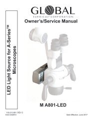
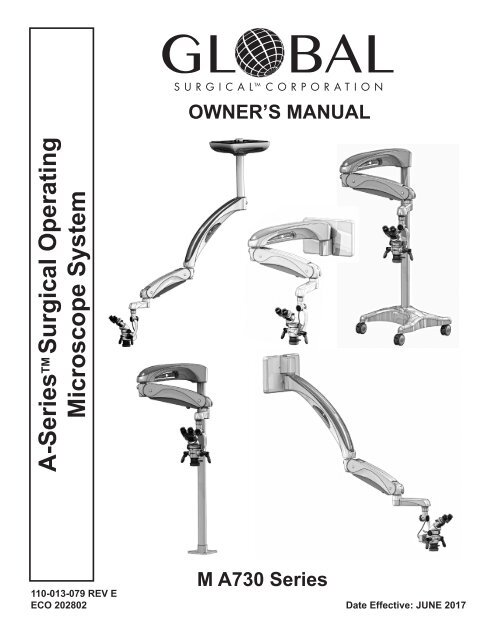
OWNER’S MANUAL<br />
A-<strong>Series</strong> TM Surgical Operating<br />
<strong>Microscope</strong> System<br />
M A730 <strong>Series</strong><br />
110-013-079 REV E<br />
ECO 202802 Date Effective: JUNE 2017
When contacting Global Surgical Corporation for either Customer Service or<br />
Technical Service, it will be helpful if you have your Customer Identification<br />
Number and your Customer Order Number available. Please take a moment<br />
to record these numbers (printed on invoice) in the spaces below.<br />
Customer Identification Number: ___________________________________<br />
Customer Order Number:__________________________________________<br />
3610 TREE COURT INDUSTRIAL BLVD.<br />
ST. LOUIS, MO 63122<br />
1-800-861-3585<br />
IF OUTSIDE THE USA:1-636-861-3388<br />
COPYRIGHT NOTICE<br />
© COPYRIGHT 2015, GLOBAL SURGICAL CORPORATION. NO PART OF THIS PUBLICATION MAY BE<br />
COPIED, PHOTOCOPIED, REPRODUCED, TRANSLATED, OR REDUCED TO ANY ELECTRONIC MEDIUM<br />
OR MACHINE-READABLE FORM, IN WHOLE OR IN PART, WITHOUT THE PRIOR WRITTEN CONSENT OF<br />
GLOBAL SURGICAL CORPORATION, 3610 TREE COURT INDUSTRIAL BLVD., ST. LOUIS, MO 63122
Congratulations on your purchase of the<br />
A-<strong>Series</strong> Surgical Operating <strong>Microscope</strong> System.<br />
We truly appreciate your business,<br />
and we’re grateful for the trust you’ve placed in us.
TABLE OF CONTENTS<br />
Section 1 Important Safety Instructions........................................................................................ 1-1<br />
1.1 Symbol Definitions.................................................................................................................. 1-1<br />
1.2 Warnings and Cautions.......................................................................................................... 1-2<br />
Section 2 Unpacking Instructions.................................................................................................. 2-1<br />
Section 3 Product Information........................................................................................................ 3-1<br />
3.1 A-<strong>Series</strong> Surgical Operating <strong>Microscope</strong> Systems.............................................................. 3-1<br />
3.2 <strong>Microscope</strong> Support Systems Configurations..................................................................... 3-1<br />
Section 4 Accessories..................................................................................................................... 4-1<br />
4.1 <strong>Microscope</strong> Components and Accessories.......................................................................... 4-1<br />
4.2 Installation of Optical Accessories........................................................................................ 4-7<br />
4.3 Installation of the Multi Focal Objective Lens...................................................................... 4-8<br />
Section 5 Operating Instructions.................................................................................................... 5-1<br />
5.1 Turning On The System.......................................................................................................... 5-1<br />
5.2 Description and Location of Controls................................................................................... 5-1<br />
5.3 Counterbalancing Adjustment............................................................................................... 5-2<br />
5.4 Spring Arm Tension Adjustment............................................................................................ 5-2<br />
5.5 Pivot Adjustment..................................................................................................................... 5-3<br />
5.6 Roll Angle Adjustment............................................................................................................ 5-3<br />
5.7 Pitch Angle Adjustment.......................................................................................................... 5-3<br />
5.8 Floorstand Locking Casters................................................................................................... 5-3<br />
5.9 <strong>Microscope</strong> Maneuvering Handles........................................................................................ 5-3<br />
5.10 <strong>Microscope</strong> Components....................................................................................................... 5-4<br />
5.11 Magnification Selection.......................................................................................................... 5-4<br />
5.12 Focusing The <strong>Microscope</strong>...................................................................................................... 5-5<br />
5.13 M A801-LED Light Source Operation..................................................................................... 5-6<br />
5.14 Brightness Settings and Memory.......................................................................................... 5-7<br />
5.15 Filter.......................................................................................................................................... 5-7<br />
5.16 Binocular Adjustment............................................................................................................. 5-8<br />
5.17 Eyepieces................................................................................................................................. 5-8<br />
5.18 Diopter Adjustment................................................................................................................. 5-8<br />
5.19 Fuse Replacement................................................................................................................... 5-9
TABLE OF CONTENTS<br />
Section 6 Care and Maintenance.................................................................................................... 6-1<br />
6.1 Cleaning and Disinfecting...................................................................................................... 6-1<br />
6.2 Cleaning the <strong>Microscope</strong> Optics............................................................................................ 6-1<br />
Section 7 Troubleshooting.............................................................................................................. 7-1<br />
7.1 Troubleshooting...................................................................................................................... 7-1<br />
Section 8 Service and Warranty...................................................................................................... 8-1<br />
8.1 Warranty Information.............................................................................................................. 8-1<br />
8.2 Technical Services Department............................................................................................. 8-2<br />
Section 9 Technical Information.................................................................................................... 9-1<br />
9.1 <strong>Microscope</strong> Support System Specifications........................................................................ 9-1<br />
9.2 Binocular Focal Lengths........................................................................................................ 9-1<br />
9.3 M A801-LED Storage and Operations Specifications.......................................................... 9-2<br />
9.4 A-<strong>Series</strong> <strong>Microscope</strong> Total Magnification Chart................................................................... 9-3<br />
9.4 Finding Total Magnification.................................................................................................... 9-4<br />
9.5 Effects of Changing Components.......................................................................................... 9-4
Section 1<br />
Important Safety Instructions<br />
! WARNING THE SAFETY AND SATISFACTION OF OUR CUSTOMERS AND THEIR PATIENTS<br />
ARE THE HIGHEST PRIORITIES OF GLOBAL SURGICAL CORPORATION. THIS<br />
MANUAL CONTAINS IMPORTANT INFORMATION REGARDING THE SAFE AND<br />
PROPER USE OF THIS EQUIPMENT AND SHOULD BE READ THOROUGHLY BY<br />
ALL OPERATORS PRIOR TO THEIR FIRST USE OF THE EQUIPMENT. FAILURE<br />
TO READ AND UNDERSTAND THIS MATERIAL COULD RESULT IN INJURY TO<br />
PATIENTS OR PERSONNEL OR IN DAMAGE TO THE EQUIPMENT.<br />
1.1 Symbol Definitions<br />
This symbol on the product is an attention symbol, alerting the user to read the<br />
Owner’s Manual for important installation, operating instructions or safety information.<br />
This symbol on the product indicates a potential electrical shock hazard and alerts the<br />
user to read the Owner’s Manual for important safety information.<br />
Symbol indicating “not for general waste.” Recycle per the EUROPEAN WASTE ELECTRICAL<br />
AND ELECTRONIC EQUIPMENT (WEEE) DIRECTIVE.<br />
This symbol indicates earth ground.<br />
For Professional Use Only.<br />
Do Not Push.<br />
This symbol indicates a surface that could be hot to the touch.<br />
This symbol alerts the user that this product emits bright light.<br />
This symbol indicates an explosion hazard.<br />
!<br />
!<br />
WARNING<br />
CAUTION<br />
NOTICE<br />
This symbol indicates a situation in which incorrect handling through disregard of a<br />
warning might result in death or serious personal injury.<br />
This symbol indicates a situation in which incorrect handling through disregard of a<br />
caution might result in personal injury or may result in damage to property.<br />
This symbol indicates a message to avoid property damage or additional information to<br />
help complete a procedure.<br />
1-1
Section 1<br />
1.2 Warnings and Cautions<br />
Important Safety Instructions<br />
! WARNING ONLY QUALIFIED PERSONNEL SHOULD WORK ON OR AROUND THIS EQUIPMENT<br />
AFTER BECOMING THOROUGHLY FAMILIAR WITH ALL WARNINGS, SAFETY<br />
NOTICES AND MAINTENANCE PROCEDURES CONTAINED HEREIN. FOR THE<br />
PURPOSES OF THIS MANUAL AND PRODUCT LABELS, A QUALIFIED PERSON IS<br />
ONE WHO HAS BEEN TRAINED ON THE INSTALLATION, CONSTRUCTION,<br />
OPERATION AND MAINTENANCE OF THIS EQUIPMENT AND WITH THE HAZARDS<br />
INVOLVED.<br />
WARNING<br />
WARNING<br />
DISCONNECT ALL ELECTRICAL POWER PRIOR TO CLEANING AND<br />
DISINFECTING. RISK OF ELECTRIC SHOCK RESULTING IN DEATH OR INJURY<br />
IS POSSIBLE IF THE ELECTRICAL POWER IS NOT DISCONNECTED PRIOR TO<br />
CLEANING THE UNIT.<br />
TO AVOID THE RISK OF ELECTRIC SHOCK, THIS EQUIPMENT MUST ONLY BE<br />
CONNECTED TO A SUPPLY MAINS WITH PROTECTIVE EARTH (=GROUND).<br />
! WARNING THIS UNIT MUST BE USED ONLY WITH HOSPITAL GRADE EARTH-GROUNDED AC<br />
OUTLETS.<br />
WARNING<br />
RISK OF EXPLOSION IF USED IN THE PRESENCE OF FLAMMABLE ANESTHETICS.<br />
! WARNING CONNECTING EQUIPMENT TO THE MULTIPLE SOCKET-OUTLET EFFECTIVELY<br />
LEADS TO CREATING A MEDICAL ELECTRICAL SYSTEM AND THE RESULT CAN<br />
BE A REDUCED LEVEL OF SAFETY.<br />
! WARNING IT IS HIGHLY RECOMMENDED THAT THE INSTALLATION OF THIS EQUIPMENT BE<br />
PERFORMED BY QUALIFIED TECHNICIANS. INSTALLATION BY UNQUALIFIED<br />
INDIVIDUALS COULD RESULT IN PERSONAL INJURY.<br />
WARNING<br />
WARNING<br />
MINIMIZE SKIN EXPOSURE BY FOCUSING THE LIGHT ON THE AREA WHERE<br />
SURGERY IS BEING PERFORMED.<br />
START THE MICROSCOPE WITH MINIMAL LIGHT INTENSITY AND INCREASE THE<br />
INTENSITY GRADUALLY. AVOID MAXIMUM INTENSITY OR USE IT FOR AS SHORT<br />
A TIME AS POSSIBLE.<br />
!<br />
WARNING NO MODIFICATION OF THE EQUIPMENT IS ALLOWED.<br />
! WARNING FAILURE TO FOLLOW THESE INSTRUCTIONS WILL RESULT IN DAMAGE TO THIS<br />
SYSTEM OR POSSIBLE INJURY (RECEIVER’S RESPONSIBILITY).<br />
WHEN OPENING THE SHIPPING CARTON THE PLASTIC BANDS WILL SPRING<br />
! WARNING APART WHEN CUT. ENSURE THEY WILL NOT HIT ANYONE OR ANYTHING. EYE<br />
PROTECTION SHOULD BE WORN WHEN REMOVING THE PLASTIC BANDS.<br />
WATCH FOR SHARP EDGES.<br />
!<br />
WARNING CONTACT GLOBAL TECHNICAL SERVICES BEFORE REPLACING THE FUSE.<br />
1-2
Section 1<br />
Important Safety Instructions<br />
!<br />
WARNING DISCONNECT ALL ELECTRICAL POWER PRIOR TO REPLACING FUSE.<br />
!<br />
WARNING USE ONLY A 5MM X 20MM CYLINDER, SLOW-BLOW, 6 AMP 250 VOLT FUSE.<br />
! WARNING NEVER REPLACE A BLOWN FUSE WITH A HIGHER-AMP FUSE. ALWAYS REPLACE<br />
THE FUSE WITH ONE WITH THE SPECIFIED AMP RATING.<br />
!<br />
CAUTION Contents are fragile and should be removed carefully.<br />
!<br />
CAUTION Some of the parts may be damaged by knives, open boxes carefully.<br />
! CAUTION After opening boxes check the serial numbers of the optics against the packing<br />
slip.<br />
!<br />
CAUTION Open boxes containing the optics over a table or counter.<br />
!<br />
CAUTION When handling the optics do not touch the glass with your fingers.<br />
! CAUTION Do not clean any surface with petroleum-based solvents such as acetone or M.E.K.<br />
(Methyl Ethyl Ketone). These solvents will remove paint and cause permanent<br />
damage to plastic surfaces. Using these solvents also presents a danger to<br />
individuals if the solvents are opened in a poorly ventilated room.<br />
! CAUTION Replacement parts, such as cables, must be purchased through Global Surgical to<br />
ensure proper compliance requirements. The use of other cables may affect EMC<br />
performance. Unauthorized use of these items will void warranty and may cause<br />
injury to you, others and/or the equipment.<br />
! CAUTION When used in clinical or residential areas near radio or TV units, this equipment<br />
may be subjected to radio interference. To avoid adverse electromagnetic effects,<br />
do not operate this equipment near RF energy equipment.<br />
! CAUTION To prevent any potential electromagnetic interference, do not use any kind of<br />
cellular phone near the equipment.<br />
NOTICE<br />
NOTICE<br />
Check for damage before discarding the shipping material and notify Global<br />
Surgical Customer Service if shipping damage is observed.<br />
Contents are packed in several boxes. Before discarding any packaging ensure no<br />
components are still within.<br />
NOTICE<br />
Save this manual for future reference.<br />
NOTICE<br />
If you have ordered accessories, then some of these may be assembled to the unit while<br />
others are supplied unassembled. Please examine the content of the box thoroughly. If<br />
any accessories require assembly, then instructions will be included.<br />
1-3
Section 1<br />
Important Safety Instructions<br />
This equipment needs special precautions regarding EMC and needs to be installed<br />
! CAUTION and put into service according to the EMC information provided in the installation<br />
manual 110-013-080 M A730 <strong>Series</strong> Installation Manual.<br />
NOTICE<br />
Portable and mobile RF communications equipment can affect medical electrical<br />
equipment.<br />
See the owner’s manual for each electrical component for<br />
specific safety and use information.<br />
Transport Position<br />
Position de Transport<br />
!<br />
CAUTION<br />
ARMS SHOULD BE FOLDED AND LOCKED IN STORAGE<br />
POSITION, AS SHOWN IN THIS FIGURE FOR SAFE<br />
TRANSPORT. FAILURE TO DO SO COULD RESULT IN<br />
DAMAGE TO THE SYSTEM OR PERSONAL INJURY.<br />
! CAUTION DO NOT PUSH UNTIL SUPPORT SYSTEM<br />
IS IN TRANSPORT POSITION.<br />
1-4
Section 2<br />
Unpacking Instructions<br />
!<br />
!<br />
!<br />
WARNING<br />
FAILURE TO FOLLOW THESE INSTRUCTIONS WILL RESULT IN DAMAGE TO THIS<br />
SYSTEM OR POSSIBLE INJURY (RECEIVER’S RESPONSIBILITY).<br />
WARNING<br />
THE PLASTIC BANDS WILL SPRING APART WHEN CUT ON THE SHIPPING BOX.<br />
ENSURE THEY WILL NOT HIT ANYONE OR ANYTHING. EYE PROTECTION SHOULD<br />
BE WORN WHEN REMOVING THE PLASTIC BANDS. WATCH FOR SHARP EDGES.<br />
CAUTION Contents are fragile and should be removed carefully.<br />
!<br />
CAUTION Some of the parts may be damaged by knives, open boxes carefully.<br />
!<br />
CAUTION After opening boxes check the serial numbers of the optics against the packing slip.<br />
!<br />
CAUTION Open boxes containing the optics over a table or counter.<br />
!<br />
CAUTION When handling the optics do not touch the glass with your fingers.<br />
NOTICE<br />
NOTICE<br />
Check for damage before discarding the shipping material and notify Global Surgical<br />
Customer Service if shipping damage is observed.<br />
Contents are packed in several boxes. Before discarding any packaging ensure no<br />
components are still within.<br />
NOTICE<br />
Save this manual for future reference.<br />
NOTICE<br />
If you have ordered accessories, then some of these may be assembled to the unit while<br />
others are supplied unassembled. Please examine the content of the box thoroughly. If any<br />
accessories require assembly then instructions will be included.<br />
All shipping materials should be retained until it has been determined that the unit was not damaged<br />
during shipment.<br />
If damage is discovered, complete the following:<br />
1. Do not refuse shipment.<br />
2. Make a notation on the delivery receipt and inspect the carton for damage.<br />
3. Take pictures of damage to the equipment and to the packaging (if evident).<br />
4. If damage is discovered, leave in original container and request immediate inspection from the carrier<br />
within 3 days.<br />
5. Contact the Global Surgical Customer Service Department at 1-800-861-3610.<br />
If the product is damaged electrically or mechanically and in the event the original packing materials are no<br />
longer available, contact Global Surgical Technical Services Department.<br />
Refer to Section 8 of this manual regarding Technical Service contact information and proceed as instructed.<br />
2-1
Section 3<br />
3.1 A-<strong>Series</strong> Surgical Operating <strong>Microscope</strong> Systems<br />
Product Information<br />
The Surgical Operating <strong>Microscope</strong> is a system of modular components intended to improve ergonomics,<br />
vision, and lighting during dental and medical procedures/examinations. If the options are chosen, the<br />
microscope system may also aid in documentation. Components may include, but are not limited to, support<br />
system, binoculars, objective lens, light source, beamsplitters, and video/photography systems. There are<br />
four support system options to choose from to meet the clinician’s needs: a floor stand model, a floor mounted<br />
model, a wall mounted model and a ceiling mounted model. All support system models provide maneuverability<br />
and sturdy, stable support for the microscope and coupler arm assemblies. These systems fold into<br />
convenient storage positions when not in use.<br />
3.2 <strong>Microscope</strong> Support Systems Configurations<br />
The A-<strong>Series</strong> <strong>Microscope</strong> Support System is available in four configurations:<br />
Floor Stand Support System Model (M A730F) The floor stand support system model is designed for<br />
portability around the office/examination room. It uses a compact H-Base with four large casters, occupying<br />
minimal floor space. All four casters may be locked to prevent rolling. As the floor stand support system is<br />
mobile, care must be taken to ensure safe transportation and to avoid any personal injury or damage to the<br />
system.<br />
M A730F<br />
FLOOR STAND<br />
shown with<br />
M A730-HA Arm System,<br />
M A1006 <strong>Microscope</strong><br />
M A1022-10 Binocular<br />
M A1061-D50 Beamsplitter<br />
M A1017 Carr Binocular Extender, 45°<br />
M A1028-250 Objective Lens<br />
3-1
Section 3<br />
Product Information<br />
Ceiling Mount Support System Model (M A730-C8, M A730-C9 and M A730C-10) The ceiling mount support<br />
system model is designed to permit maximum range of operation while eliminating the use of floor space.<br />
M A730C<br />
CEILING MOUNT<br />
M A730-C8 Ceiling Mount for a mounting height of 8 foot<br />
M A730-C9 Ceiling Mount for a mounting height of 9 foot<br />
M A730-C10 Ceiling Mount for a mounting height of 10 foot<br />
shown with<br />
M A730-45A Arm System,<br />
M A1006 <strong>Microscope</strong><br />
M A1022-10 Binocular<br />
M A1061-D50 Beamsplitter<br />
M A1017 45° Binocular Extender<br />
M A1028-250 Objective Lens<br />
Floor Mount Support System Model (M A730FM) and Thru The Floor Mount (M A730FMT)<br />
The floor mount support system model is designed to be installed on the floor in a fixed location within the<br />
office/examination room.<br />
M A730FM<br />
FLOOR MOUNT<br />
M A730FMT<br />
FLOOR MOUNT THROUGH<br />
THE FLOOR<br />
shown with<br />
M A730-HA Arm System,<br />
M A1006 <strong>Microscope</strong><br />
M A1022-10 Binocular<br />
M A1061-D50 Beamsplitter<br />
M A1017 45° Binocular Extender<br />
M A1028-250 Objective Lens<br />
3-2
Section 3<br />
Product Information<br />
Wall Mount Support System Model (M A730W) The wall mount support system model is designed for areas<br />
with limited floor space. It provides an unobstructed range of working area and folds flat against the wall for<br />
convenient storage.<br />
M A730W<br />
WALL MOUNT<br />
shown with<br />
M A730-HA Arm System,<br />
M A1006 <strong>Microscope</strong><br />
M A1022-10 Binocular<br />
M A1061-D50 Beamsplitter<br />
M A1017 45° Binocular Extender<br />
M A1028-250 Objective Lens<br />
M A730W<br />
HIGH WALL MOUNT<br />
shown with<br />
M A730-45A Arm System,<br />
M A1006 <strong>Microscope</strong><br />
M A1022-10 Binocular<br />
M A1061-D50 Beamsplitter<br />
M A1017 45° Binocular Extender<br />
M A1028-250 Objective Lens<br />
3-3
Section 4<br />
4.1 <strong>Microscope</strong> Components and Accessories<br />
Accessories<br />
<strong>Microscope</strong> Head<br />
The A-<strong>Series</strong> M A1003 <strong>Microscope</strong> provides the user with 3 steps of magnification, the M A1004<br />
provides 4 steps of magnification and the M A1006 <strong>Microscope</strong> provides 6 magnification steps.<br />
Each of the A-<strong>Series</strong> <strong>Microscope</strong>s may be used with a variety of A-<strong>Series</strong> binoculars, objective lenses and<br />
other accessories.<br />
M A801-LED<br />
The A-<strong>Series</strong> M A801-LED Light Source provides light to the surgical site for illumination and improved optical<br />
clarity.<br />
4-1
Section 4<br />
M A1047LFM Laser Filter<br />
Accessories<br />
This laser filter is meant for use with a corresponding specific wavelength laser and A-<strong>Series</strong> <strong>Microscope</strong><br />
System equipped with a M A1047LFM laser filter module.<br />
M A1047LFM<br />
M 1047LFERB<br />
M 1047LFEC2<br />
M 1047LFARG<br />
M 1047LFYG3<br />
M A1019 Binocular Rotation Ring<br />
Allows for better operator positioning. Rotates the binocular +/- 25 degrees.<br />
M A512 Dual Iris Diaphragm<br />
Allows for greater depth of field which is particularly valuable for photography.<br />
M A1061-D50 & M A1061-DVA50 Dual Port Beamsplitter<br />
The dual port beamsplitter models have two (2) mounting ports for camera adapters. This allows the<br />
simultaneous use of a still camera and video camera if so desired, but other configurations are certainly<br />
feasible. The dual port beamsplitters can be configured with either one 50/50 prism and one 95/5 prism,<br />
M A1061-DVA50 or with two 50/50 prisms, M A1061-D50. The beamsplitter can mount to the microscope with<br />
either prism on the right or left, depending on personal preference. The choice of which prisms to use should<br />
be based on the type of cameras intended to be mounted to the microscope.<br />
4-2
Section 4<br />
M A1061-SVA & M A1061-S50 Single Port Beamsplitter<br />
Accessories<br />
The single port beamsplitter models have one (1) mounting port for a camera adapter. The beamsplitter can<br />
be configured with a 50/50 prism M A1061-S50 or 95/5 prism M A1061-SVA. The M A1061-S50 model directs<br />
50% of the light through the microscope toward a camera mounted on the side of the beamsplitter, while<br />
the other 50% of light passes through to the user’s eye. The M A1061-SVA prism directs only 5% of the light<br />
toward the camera while the other 95% of the light passes through to the user’s eye. The beamsplitter can<br />
mount to the microscope with the port oriented toward the user’s right or left, depending on personal<br />
preference. The choice of which prism to use should be based on the type of camera intended to be mounted<br />
to the microscope.<br />
M A1017 Carr Adapter, 45° Binocular Extender<br />
Provides ergonomic benefits by positioning the binocular higher and further from the microscope body.<br />
M A1022 <strong>Series</strong> Binoculars<br />
The inclinable binoculars allow for 0-220 degrees of tilt articulation. This feature accommodates multiple user<br />
heights while maintaining optimal ergonomic posture. It also allows the user to maintain this posture while<br />
moving the microscope head.<br />
4-3
Section 4<br />
M A1021 <strong>Series</strong> Binoculars,<br />
Accessories<br />
The inclined binoculars are a more economical choice, but limited to a fixed 45 degree tilt angle.<br />
M A1020 <strong>Series</strong> Binoculars<br />
The straight binoculars are for use in ENT and otolaryngology and may also be used with the binocular coobservation<br />
systems.<br />
M A1028-200, M A1028-250, M A1028-300 Objective Lens<br />
Convenient fine focus feature allows for easy adjustment of objective lens. Range of 20mm allows for easy<br />
focus adjustment without moving the microscope. The M A1028-200 provides 200mm working distance<br />
between the lens and the surgical site; the M A1028-250 provides 250mm and the M A1028-300 provides<br />
300mm.<br />
M 1028ML Multi-Focal Objective Lens<br />
275<br />
200<br />
The Multi-Focal Objective Lens allows the user to focus the microscope on an object anywhere between 200<br />
and 350mm away from the microscope without having to move the microscope. This promotes optimal<br />
ergonomic comfort and minimal adjustment throughout multiple procedures.<br />
M A517HD1080 <strong>Series</strong> HD Color Video Camera<br />
The M A517HD1080 <strong>Series</strong> high definition camera outputs HDMI video at true 1080p HD resolution. The 1/3”<br />
C-mount design offers a compact and lightweight HD video solution. The on-camera push-button is used for<br />
one-push white balance and push-hold for image flip. Use with camera adapter M A528STHDC.<br />
4-4
Section 4<br />
M A794XA-730 UltraSource II TM Xenon LightSource<br />
Accessories<br />
The UltraSource II TM Xenon LightSource is a high efficiency light source utilizing Xenon illumination technology.<br />
M A730-717 17” Support Extension Arm<br />
Provides additional reach for the microscope system for use in a wide variety of office applications. This arm<br />
can be used to avoid other obstacles in offices such as x-ray units or cabinets.<br />
Eyecups<br />
M 1039GL<br />
Long Silicone Eyecup for A and G-<strong>Series</strong> Binocular<br />
5/8 inches tall for Aand G-<strong>Series</strong> binocular this is the ideal eyecup for users who do not wear glasses.<br />
M 1039G<br />
Low Profile<br />
Short Silicone Eyecup for A-<strong>Series</strong> Binocular<br />
Low profile 5/16 inches silicone eyecup for A-<strong>Series</strong> binocular. This is the ideal eyecup for users who wear<br />
glasses.<br />
4-5
Section 4<br />
Multiple Socket-Outlet<br />
Accessories<br />
! WARNING ONLY CONNECT ITEMS THAT GLOBAL SURGICAL HAS SPECIFIED AS BEING<br />
COMPATIBLE WITH THE MICROSCOPE SYSTEM. CONNECTING EQUIPMENT<br />
THAT IS NOT INTENDED FOR USE WITH THE MICROSCOPE SYSTEM TO THE<br />
MULTIPLE SOCKET OUTLETS MAY RESULT IN INJURY AND/OR DAMAGE TO<br />
THE MICROSCOPE SYSTEM.<br />
! WARNING CONNECTING ELECTRICAL EQUIPMENT TO THE MULTIPLE SOCKET<br />
OUTLETS EFFECTIVELY LEADS TO CREATING A MEDICAL EQUIPMENT<br />
SYSTEM AND THE RESULT CAN BE A REDUCED LEVEL OF SAFETY.<br />
! WARNING ADDITIONAL MULTIPLE SOCKET OUTLETS AND/OR EXTENSION CORDS<br />
SHOULD NOT BE CONNECTED TO THE MICROSCOPE SYSTEM’S MULTIPLE<br />
SOCKET OUTLETS.<br />
Multiple Socket<br />
Outlet<br />
Multiple Socket<br />
Outlet<br />
Fixed Horizontal Arm<br />
45° Arm<br />
Figure 4-1 Multiple Socket Outlet<br />
The multiple socket outlet provided with the microscope system allows for attaching additional equipment to aid<br />
in vision, lighting and documentation.<br />
These outlets should only be used for supplying power to equipment that is intended to form part of the<br />
medical equipment system: digital camera, video camera, Xenon Ultrasource LightSource, and TV<br />
monitor. Please refer to International Standard IEC 60601-1:2005, Medical electrical equipment – Part 1:<br />
General requirements for basic safety and essential performance, for the requirements that are applicable to a<br />
medical equipment system.<br />
The maximum permitted load for the microscope system is 240 VAC.<br />
4-6
Section 4<br />
4.2 Installation of Optical Accessories<br />
Accessories<br />
Installation of the A-<strong>Series</strong> Binocular<br />
To install the binocular, Refer to Figure 4-2 and proceed as follows:<br />
1. Loosen the set screw on the microscope body with a 5/64” hex wrench so it will not interfere with<br />
the dovetail-shaped bottom of the binocular head.<br />
2. Slide the binocular head into the retaining ring so the dovetail-shaped bottom slides under the two<br />
wedge-shaped tabs at the rear of the retaining ring.<br />
3. To align the binocular, position the binocular head so the U-Shaped slot at the rear of the binocular base is<br />
installed over the slotted screw in the binocular retaining ring.<br />
4. Tighten the set screw. When the microscope body and the binocular head are properly aligned, the<br />
binocular head will not rotate in the binocular retaining ring.<br />
NOTICE<br />
M A1047LFM Laser Filter, M A1019 Binocular Rotation Ring, M A512 Dual Iris Diaphragm,<br />
M A1061-D50 & M A1061-DVA50 Dual Port Beamsplitter, M A1061-SVA & M A1061-S50 Single<br />
Port Virtual Beamsplitter, M A1017 Carr Adapter will install in very much the same way. See the<br />
installation instructions that are included with each accessory.<br />
Binocular<br />
<strong>Microscope</strong> Body<br />
,<br />
Set Screw<br />
<strong>Microscope</strong> Body<br />
Objective Lens<br />
Figure 4-2 Installation of the A-<strong>Series</strong> M A1003, M A1004, and M A1006 Optics<br />
4-7
Section 4<br />
4.3 Installation of the Multi Focal Objective Lens<br />
Accessories<br />
To install the threaded objective lens to the microscope body, Refer to Figure 4-3 and proceed as follows:<br />
NOTICE<br />
The knob is shipped unattached. Do not attach until after the multi-focal lens is assembled to<br />
the microscope.<br />
1. Ensure the lock ring is threaded down fully on the Multi Focal lens before installing the lens on the<br />
microscope body.<br />
2. Thread the Multi Focal lens into the microscope body in the direction of the arrow shown until the lens<br />
stops.<br />
3. The knob location can be positioned for user comfort. Back the lens out of the microscope body<br />
(NO MORE THAN 1 FULL TURN) to position the knob shaft in the desired location (right side for righthanded<br />
user or left side for left-handed user is recommended).<br />
4. While holding the multi-focal lens body, turn the lock ring until it is tight against the bottom of the<br />
microscope body. This prevents the multi-focal lens from rotating after installation.<br />
5. Attach the knob by pushing it onto the shaft until fully seated.<br />
NOTICE<br />
The M A1028-200, M A1028-250 and M A1028-300 fine focus will install in very much the same<br />
way. See the installation instructions that are included with each accessory.<br />
<strong>Microscope</strong><br />
Body<br />
Lock Ring<br />
Shaft<br />
Multi-Focal<br />
Lens<br />
Knob<br />
Figure 4-3 Installation of the A-<strong>Series</strong> M A1028ML Multi-Focal Lens<br />
4-8
Section 5<br />
5.1 Turning On The System<br />
Operating Instructions<br />
! WARNING THIS UNIT MUST BE USED ONLY WITH HOSPITAL GRADE EARTH-GROUNDED AC<br />
OUTLETS.<br />
Plug in the system into a hospital grade earth-ground AC outlet. Turn power on to the system by depressing<br />
the LED power button. The green indicator light(s) at the lowest setting will come on indicating that there is<br />
power to the system and the intensity setting. When the LED power button is depressed again the light(s) will<br />
extinguish indicating that the power to the system is turned off. Depress the power button again and the LED<br />
will come on at the last intensity setting used. See Section 5.13 “M A801-LED Light Source Operation” or the<br />
LED owner’s manual 110-013-081 for instructions.<br />
If set up with a wall switch make sure the wall switch<br />
is turned on and then depress the LED power button.<br />
To safely terminate the operation of the<br />
microscope system, unplug the microscope<br />
or turn off the microscope via wall switch where applicable.<br />
Power Button<br />
Indicator light<br />
at the<br />
lowest<br />
setting<br />
5.2 Description and Location of Controls<br />
Figure 5-1 Power Button<br />
Figure 5-2 shows the location of the system controls.<br />
Straight Arm Pivot<br />
Adjustment<br />
Extension Arm Pivot<br />
Adjustment<br />
Spring Arm Pivot<br />
Adjustment<br />
Counterbalance<br />
Adjustment<br />
(set screw)<br />
<strong>Microscope</strong> Pivot<br />
Adjustment<br />
Roll Angle<br />
Adjustment<br />
Locking Casters<br />
Lock<br />
Spring Arm Tension<br />
Adjustment<br />
Pitch Angle<br />
Adjustment<br />
<strong>Microscope</strong><br />
Maneuvering<br />
Handle<br />
<strong>Microscope</strong><br />
Maneuvering<br />
Handle<br />
Figure 5-2 Location of Controls<br />
5-1
Section 5<br />
Operating Instructions<br />
It is best to set the feel of the microscope before attempting to use the microscope so the user comfort is<br />
optimized for the microscope procedures.<br />
5.3 Counterbalancing Adjustment<br />
Counterbalancing is done to ensure the microscope head moves with very little pressure (typically from user<br />
pressing on the eyecups) To do this the weight of the microscope head must be counterbalanced with the<br />
spring arm.<br />
The upward lift of the spring arm assembly can be adjusted to match the weight of the microscope and its<br />
accessories. This adjustment is called “counterbalancing”. Before adjusting the counterbalance, ensure that<br />
all accessories are installed on the microscope and the spring arm tension adjustment knob is loose. To loosen<br />
the spring arm tension adjustment knob turn the knob clockwise. Insert the 3/16” hex wrench into the center<br />
hex-socket screw (located under the end of the spring arm assembly that attaches to the horizontal arm) and<br />
turn the tool to the right (clockwise) if the microscope falls when released, or turn the tool to the left (counterclockwise)<br />
if the microscope rises when released.<br />
See Figure 5-3<br />
Insert the 3/16” hex wrench<br />
into the center hex-socket<br />
screw<br />
Bottom View<br />
Figure 5-3 Counterbalancing Adjustment<br />
5.4 Spring Arm Tension Adjustment<br />
Adjusts the amount of tension required to move the spring arm up and down. Turn the knob to adjust the spring<br />
arm tension. See Figure 5-2<br />
5-2
Section 5<br />
5.5 Pivot Adjustment<br />
Operating Instructions<br />
Adjusts the amount of effort required to rotate the spring arm and extension arm from side to side. Push in the<br />
pivot knob until it pops out. Turn the pivot adjustment knob to the right to tighten the tension or turn to the left to<br />
loosen the tension. See Figure 5-4<br />
Horizontal Arm<br />
Push in the knob<br />
and turn to adjust<br />
the tension of the<br />
horizontal arm<br />
Push in the knob<br />
and turn to adjust<br />
the tension of the<br />
spring arm<br />
Push in the knob<br />
and turn to adjust<br />
the tension of the<br />
extension arm<br />
Extension Arm<br />
Spring Arm<br />
Turn collar to adjust the<br />
tension of the coupler arm<br />
5.6 Roll Angle Adjustment<br />
Figure 5-4 Pivot Adjustment<br />
Adjusts the amount of tension required to rotate the microscope right or left. It can be adjusted by tightening or<br />
loosening the roll angle adjustment knob. This knob is located at the rear of the coupler arm. See Figure 5-5<br />
5.7 Pitch Angle Adjustment<br />
Adjusts the amount of tension required to rotate the microscope forward or backward. It is adjusted by<br />
tightening or loosening the pitch angle adjustment knob. This knob is located on the right side of the<br />
microscope body. See Figure 5-5<br />
5.8 Floorstand Locking Casters<br />
To secure the support system after it is rolled to its desired location, engage the locks on the casters. The lock<br />
is pushed down to obstruct regular wheel movement. This fixes the support system into a desired place. You<br />
can pull up the caster lock to release the wheel and move the support system, if necessary. See Figure 5-2<br />
5.9 <strong>Microscope</strong> Maneuvering Handles<br />
Maneuvering handles can be adjusted to user’s preferred position. To change the position of the maneuvering<br />
handles, depress the handles in towards the body of the microscope. While depressing the handles, position<br />
the handles to a position comfortable for your purposes and then release the handles. The handles will lock<br />
into place. See Figure 5-5<br />
5-3
Section 5<br />
5.10 <strong>Microscope</strong> Components<br />
Operating Instructions<br />
Diopter Adjustment<br />
Rings<br />
Pivot<br />
Adjustment<br />
Roll Angle<br />
Adjustment<br />
Coupler Arm<br />
Indicator Arrow<br />
Magnification<br />
Selector Knob<br />
Pitch Angle<br />
Adjustment Knob<br />
Magnification<br />
Selector Knob<br />
<strong>Microscope</strong><br />
Maneuvering<br />
Handle<br />
Objective Lens<br />
5.11 Magnification Selection<br />
<strong>Microscope</strong> Head<br />
Figure 5-5 <strong>Microscope</strong> Components<br />
<strong>Microscope</strong><br />
Maneuvering<br />
Handle<br />
All A-<strong>Series</strong> M A1003, M A1004 and M A1006 <strong>Microscope</strong>s have two magnification factor selection knobs, one<br />
on each side of the microscope body. Either of these knobs should be turned until the desired magnification<br />
factor is facing the indicator arrow on the left side of the microscope body.<br />
See Section 9, Technical Information, for the magnification and focal length information.<br />
5-4
Section 5<br />
5.12 Focusing The <strong>Microscope</strong><br />
Operating Instructions<br />
The coarse focus on the microscope system is achieved by raising or lowering the microscope assembly with<br />
the spring arm. Fine focus is obtained by moving the fine focus objective lens.<br />
The parfocal adjustment of the microscope allows the user to adjust the eyepieces to correct for<br />
nearsightedness or farsightedness. It is essential to perform the parfocal adjustment prior to using any still or<br />
video camera applications. If the parfocal adjustment is not performed, the microscope can still be focused on<br />
a selected magnification, but other magnification settings may not be in focus.<br />
The steps listed below should be followed for making the parfocal adjustments on the microscope:<br />
1. Each operator of the microscope will require his or her own parfocal settings which should be<br />
set before any procedures are performed. Due to changes in eye correction associated<br />
with time, it is recommended that this procedure be performed by each operator a minimum of<br />
one time per year.<br />
2. Position the microscope above a flat stationary surface, with the bottom of the objective lens parallel to the<br />
surface.<br />
3. Using a pen or pencil, mark an “X” on a piece of white paper for a focusing target and place it in<br />
the center of the illumination field of the microscope.<br />
4. Depress the diopter tension lever and set the diopter adjustment rings on both eyepieces to “0”.<br />
See Section 5.18 for additional information.<br />
5. Without looking through the binoculars, adjust the fine focus objective lens to its approximate midpoint.<br />
6. Set the magnification to the highest setting. Raise or lower the microscope vertically until the “X”<br />
is in optimum focus.<br />
7. Adjust the fine focus objective lens until a sharp focus is acquired.<br />
8. Tighten the spring arm tension adjustment (See Figure 5-2 for location) on the spring arm assembly to<br />
prevent the microscope from moving. Set the magnification to the lowest setting. Focus both<br />
eyepieces, one at a time, by turning the diopter adjustment ring until the image is clear and sharp.<br />
NOTICE<br />
It is particularly important to perform the parfocal procedure when an image through the<br />
microscope is clear but the same image through a still or video camera is not focused, or<br />
vice-versa.<br />
Use direct vision whenever possible to free hands for instruments.<br />
5-5
Section 5<br />
5.13 M A801-LED Light Source Operation<br />
Operating Instructions<br />
Once the light source is installed, it is ready for operation. The light source has instant on/off capabilities. The<br />
power button will toggle power off and on with each press of the button. When power is first applied to the light<br />
source, the green bottom indicator light will turn on. When the power button is pressed off and then on again<br />
the last level used will be illuminated. See Figure 5-6<br />
!<br />
NOTICE<br />
WARNING<br />
BEFORE operating the light source, refer to the Owner’s Manual 110-013-081<br />
for any warnings and cautions associated with the use of the Light Source to<br />
ensure safe operation.<br />
The LED light source has been tested according to IEC 60601-2-57 Non-laser light<br />
source. The test results show no photobiological hazard associated with the use of<br />
this LED light source as it is intended, to include hazards associated with blue light<br />
wavelengths.<br />
Filter Lever<br />
Green Indicator<br />
Lights<br />
Press +<br />
to increase intensity<br />
Keypad/Control<br />
Panel<br />
Press -<br />
to decrease intensity<br />
Power Button<br />
Press to<br />
Turn ON or OFF<br />
Figure 5-6 LED Control Panel<br />
5-6
Section 5<br />
5.14 Brightness Settings and Memory<br />
Operating Instructions<br />
There are nine levels of brightness which can be selected using the and buttons while the power is on.<br />
The level of brightness is indicated by the green indicator lights located on the keypad/control panel. An<br />
indicator light will light up for each increase in brightness. See Figure 5-6.<br />
The button is used to increase brightness setting. Each press will increase light source brightness. Any<br />
additional press of will have no effect once the highest setting is reached.<br />
The button is used to decrease brightness setting. Each press will decrease light source brightness. Any<br />
additional press of will have no effect once the lowest setting is reached.<br />
Each button performs its intended function when the button is pressed. Holding a button has no effect. For<br />
example to increase the brightness from minimum to maximum, the user must press and release the<br />
button eight times. Pressing and holding the button will only increase the brightness to the next higher<br />
setting.<br />
The light source has a recall feature. This feature remembers the last level of brightness used before being<br />
powered off. Any time the light source is powered on, the brightness level will be at the last level used.<br />
5.15 Filter<br />
The LED light source emits white light, which includes all the colors of light combined in the visible light<br />
spectrum. Depending on what area of the patient is illuminated, a filter may be used to enhance the<br />
observation through the microscope. The LED light source has two kinds of filters: an amber filter (composite)<br />
and a green filter.<br />
The use of the amber filter (composite) helps reduce the emissions of wavelengths below 520 nm (blue light)<br />
which are used to cure dental resins.<br />
The use of the green filter provides a higher contrast of tissue by reducing the emissions of wavelengths<br />
around 650 nm (red light).<br />
See M A801-LED Owner’s Manual 110-013-081 for operation information.<br />
Filter Lever DOWN<br />
for<br />
NO FILTER<br />
Filter Lever CENTER<br />
for<br />
AMBER DENTAL COMPOSITE<br />
FILTER<br />
Filter Lever UP<br />
for<br />
GREEN FILTER<br />
Figure 5-7 LED Filter<br />
5-7
Section 5<br />
5.16 Binocular Adjustment<br />
Operating Instructions<br />
The distance between the user’s eyes is called the inter-pupillary distance. The inter-pupillary distance of the<br />
binocular must be adjusted to match the user’s eyes in order to maintain proper stereoscopic vision. To adjust<br />
the binocular, the user should look into both eyepieces, grasp the binocular by the side and spread the<br />
eyepieces apart or move them closer together until a single image forms. A grid of the inter-pupillary distance<br />
in millimeters is engraved on the binocular for reference.<br />
Grasp the binocular by the side and<br />
spread the eyepieces apart or move<br />
them closer together until a single<br />
image forms<br />
5.17 Eyepieces<br />
The eyepieces used on A-<strong>Series</strong> <strong>Microscope</strong>s are high eye point eyepieces. This means that a full-sized image<br />
is formed approximately one inch (25 mm) above the eyepiece to assist users who wear glasses.<br />
Eyecups are used to position the user’s head at the correct distance from the eyepiece without the user<br />
becoming fatigued. The eyecups on the A-<strong>Series</strong> M A1003, M A1004, M A1006 <strong>Microscope</strong>s are adjustable<br />
to provide maximum comfort for the user. To lower the eyecup, grasp the rubber eyecup and turn it clockwise.<br />
Turning it counterclockwise will raise the eyecup. The eyecups are properly adjusted when the user’s eyes<br />
(or glasses) are touching the eyecups with the image through the microscope in full view. Reference lines are<br />
provided on the outside surface of the eyecups to verify that both are adjusted to the same height.<br />
5.18 Diopter Adjustment<br />
Each binocular eyepiece is equipped with a diopter adjustment ring which is marked in plus(+) or minus(-)<br />
one diopter increments. To adjust the diopter setting, firmly grasp the diopter adjustment ring and adjust the<br />
settings until the image is clear and sharp.<br />
The diopter adjustment corrects for the user’s vision prescription, providing relaxed 20/20 vision with or without<br />
glasses or contact lenses. The diopter adjustment has a correction range of +5 diopters to -5 diopters. Users<br />
with natural correction outside this range must wear additional corrective lenses to achieve relaxed 20/20<br />
vision.<br />
5-8
Section 5<br />
Operating Instructions<br />
Diopter Adjustment Ring<br />
Image through the Binocular<br />
should form a single circle as shown at the right.<br />
IPD Wrong<br />
5.19 Fuse Replacement<br />
Figure 5-9 Diopter Adjustment<br />
IPD Correct<br />
!<br />
!<br />
!<br />
WARNING CONTACT GLOBAL TECHNICAL SUPPORT BEFORE REPLACING THE FUSE.<br />
WARNING DISCONNECT ALL ELECTRICAL POWER PRIOR TO REPLACING FUSE.<br />
WARNING USE ONLY A 5MM X 20MM CYLINDER, SLOW-BLOW, 6 AMP 250 VOLT FUSE.<br />
! WARNING NEVER REPLACE A BLOWN FUSE WITH A HIGHER-AMP FUSE. ALWAYS REPLACE THE<br />
FUSE WITH ONE WITH THE SPECIFIED AMP RATING.<br />
The fuse protects your electrical components in the system from a sudden and unexpected power surge.<br />
To replace the fuses follow the steps below:<br />
1. Unplug the power cord from the outlet to remove power to the system.<br />
2. Remove the screw(s) holding the cover on the arm. See Figure 5-10<br />
3. Remove the cover.<br />
4. Open the fuse compartment cover.<br />
5. Remove both fuses even if only one fuse is blown.<br />
6. Replace with two (2) new 5mm x 20mm cylinder, slow-blow, 6 Amp 250 Volt Fuses.<br />
7. Replace arm cover and insert screw(s) into arm and tighten.<br />
8. Plug the power cord back into the outlet.<br />
5-9
Section 5<br />
Operating Instructions<br />
NOTICE<br />
If your new fuse blows soon after installing it, you could have problems in that circuit. Contact<br />
Global Surgical Technical Support for assistance.<br />
Remove Cover<br />
Remove 2 Screws<br />
and Remove Cover<br />
Open Fuse Compartment<br />
Replace with Two (2)<br />
6 Amp 250V Fuses<br />
Remove Cover<br />
Remove Screw<br />
Horizontal Fixed Arm Version<br />
Open Fuse<br />
Compartment<br />
Replace with<br />
Two (2) 6 Amp<br />
250V Fuses<br />
45° Arm Version<br />
Figure 5-10 Fuse Replacement<br />
5-10
Section 6<br />
Care and Maintenance<br />
WARNING<br />
DISCONNECT ALL ELECTRICAL POWER PRIOR TO CLEANING AND DISINFECTING.<br />
RISK OF ELECTRIC SHOCK RESULTING IN DEATH OR INJURY IS POSSIBLE IF THE<br />
ELECTRICAL POWER IS NOT DISCONNECTED PRIOR TO CLEANING THE UNIT.<br />
NOTICE<br />
Clean and disinfect after every patient according to CDC and OSHA requirements for<br />
non-critical devices.<br />
6.1 Cleaning and Disinfecting<br />
1. The support system can be cleaned with any cleaning agent, which is used for external cleaning of<br />
electrical equipment, according to instructions given by the manufacturer of the cleaning solution. Do not<br />
use cleaning agents that are not permitted for use with plastics, i.e., ammonia, acetone, salty acids<br />
(HCI), etc.<br />
2. Do not allow excessive moisture or liquids to come in direct contact with the unit.<br />
3. Avoid spraying optical components.<br />
4. Do not allow cleaning agents or liquids to enter the power input.<br />
5. Use any disinfectant agents which are commonly applied while disinfecting surfaces of electric medical<br />
equipment. Such disinfectant agents are usually in the form of sprays or damp cloths.<br />
6. Follow the instructions given by the manufacturer of the disinfectant solution.<br />
6.2 Cleaning the <strong>Microscope</strong> Optics<br />
The exposed lens surfaces of the microscope system should only be cleaned when necessary to remove dust,<br />
fingerprints and other smudges. Handling optics increases their chances of getting dirty or damaged.<br />
Extreme care should be taken to avoid scratching the coated surfaces of the lenses. You should not touch any<br />
exposed lens surfaces as oil and debris from your hands can stain or damage optical coatings.<br />
Use a low-lint soft cloth wetted with isopropyl alcohol in a circular motion starting in the center and working out<br />
towards the edge of the lens. Clean edges with a low-lint cotton-tipped swab.<br />
6-1
Section 7<br />
7.1 Troubleshooting<br />
Troubleshooting<br />
Table 7-1 (below) lists some symptoms, possible causes and solutions.<br />
Table 7-1 Troubleshooting Guide<br />
Symptoms<br />
Solutions<br />
Ensure that the AC power cord is properly connected.<br />
No power to the system<br />
System arms are hard to<br />
rotate right to left<br />
Vertical movement is<br />
difficult<br />
Vertical position of arms/<br />
microscope doesn’t stay in<br />
position when released<br />
System arms drift<br />
horizontally on their own<br />
Floorstand seems unstable<br />
Verify building circuit breaker is not tripped, or that another device works in<br />
the same outlet.<br />
Check the system’s fuses. If necessary, replace. Replace both fuses if either<br />
is blown.<br />
The spring arm tension adjustment knob is adjusted too tight.<br />
Adjust counterbalance per Section 5.3.<br />
Adjust counterbalance per Section 5.3.<br />
Apply slight tension to the spring arm tension adjustment. If still drifting,<br />
ensure wall, floor mount, or ceiling mount is installed level and plumb.<br />
If floorstand arms are still drifting, move to a different location on the floor<br />
and ensure column screws are tight.<br />
Ensure that both weights are installed in the base (under the plastic cover)<br />
Floorstand is difficult to roll<br />
Ensure that all the casters are unlocked.<br />
Remove horizontal arm, spring arm, or 45 degree arm, and extension arm<br />
covers. Check for damaged or pinched cable.<br />
LED light source does not<br />
turn on<br />
For all other issues not<br />
covered above<br />
Ensure filter lever is located at one of the three correct positions.<br />
Remove horizontal or 45 °arm cover, check to ensure that the LED power<br />
cord is securely plugged into one of the plugs on the multiple socket outlet<br />
located in the horizontal or 45° arm.<br />
Call Global Surgical Technical Services See Section 8.2 for contact<br />
information.<br />
7-1
Section 8<br />
Service and Warranty<br />
8.1 Warranty Information<br />
Global Surgical Corporation warranty information is located at:<br />
http://www.globalsurgical.com/warranty.html<br />
90-Day Money-back Guarantee on <strong>Microscope</strong>s and Accessories.<br />
The microscope and microscope accessories you purchase will be unconditionally guaranteed and risk-free.<br />
You may return a product to Global in good condition for any reason within 90 days of invoice and receive a full<br />
product refund. Custom microscope parts are excluded from this policy. This money-back guarantee applies to<br />
the U.S. and Canada only.<br />
<strong>Microscope</strong> Limited Lifetime Warranty<br />
Your microscope will include an unprecedented lifetime warranty, including parts and labor, for all optical and<br />
support components. Please refer to detailed Limited Lifetime Warranty below.<br />
Upgradeable<br />
We will continue to do our best to design our microscopes to be modular and upgradeable, thus greatly minimizing<br />
the possibility of obsolescence.<br />
<strong>Microscope</strong> Limited Lifetime Warranty<br />
Except as set forth in this Limited Lifetime Warranty, Global Surgical Corporation (the “Company”) hereby warrants that each microscope<br />
product manufactured and sold by the company (“Product”) shall be free from defects in materials and workmanship under normal<br />
use and service for the life of the product. This warranty is non-transferable and is valid only with respect to the original purchase of<br />
the product. The Company’s obligation under this warranty shall be limited to repairing or replacing at the Company’s facility and at the<br />
Company’s expense, any parts of components that are demonstrated to be defective. The purchaser shall be responsible for shipment<br />
of the product to and from the Company’s facility at 3610 Tree Court Industrial Boulevard, St. Louis, Missouri, 63122, Attention: Technical<br />
Service, or such other facility as the Company may otherwise designate. Under certain circumstances which are pre-approved by<br />
the Company, necessary repairs may be made at the purchaser’s facility.<br />
A return authorization is required before returning any product for warranty service by calling 1-800-861-3610. The customer is responsible<br />
for all shipping expenses. Global Surgical suggests using a method that will allow you to track the package in the event it does not<br />
arrive. Global also recommends you insure the package.<br />
This warranty shall not be applicable to: (l) any electrically-driven products sold by the Company, (II) any products which are not manufactured<br />
by the Company which may be attached to the product, such as video equipment, camera equipment, recording devices, monitors,<br />
printers (III) any components which are consumable or are required to be replaced or disposed of in connection with normal use of<br />
the product, such as lamps, fiber optic cables, rubber eyecups and drapes, or (IV) any product which was purchased prior to April 27,<br />
1994.<br />
This warranty shall be void and of no effect: (I) if the product is damaged due to misuse, use in a manner other than pursuant to the<br />
instructions for the use of Product, abuse, physical mishandling or natural causes such as flood, fire, earthquake, or other perils, as<br />
determined by the Company, or (II) if any repairs or replacements are made by persons not authorized by the Company to perform such<br />
services.<br />
The warranties set forth herein are in lieu of any and all other warranties, expressed or implied, including, without limitation, warranties<br />
of merchantability and fitness for a particular purpose. Purchaser’s rights thereunder are granted in lieu of any other rights purchaser<br />
may have and purchaser hereby waives all other rights, warranties, remedies or guarantees whatsoever with respect to the product.<br />
The Company shall not be liable for any third parties with respect to the product or its performance. Further, the Company shall not be<br />
liable for, and purchaser hereby releases the Company from any direct, or indirect, consequential, special, and incidental or punitive<br />
damages with respect to the product. In no event shall the Company be liable for any breach of warranty or other claim in an amount<br />
exceeding the purchase price of the product.<br />
Warranty for <strong>Microscope</strong> products not included in the Limited Lifetime Warranty:<br />
Electrical and electronic components, except for the LED lightsource, have a one-year warranty. The LED lightsource has a three-year<br />
warranty.<br />
Consumables such as fiber optic cables, eyecups etc., have a one-year warranty. Light bulbs have a warranty equal to that given by<br />
the manufacturer.<br />
This warranty applies to the U.S. and Canada only.<br />
For international warranty information: Email: international@globalsurgical.com<br />
Phone: 1-636-861-3388, Fax: 1-636-861-2969<br />
8-1
Section 8<br />
8.2 Technical Services Department<br />
Service and Warranty<br />
When contacting our Technical Services Department, you will be served by highly knowledgeable representatives in an<br />
efficient manner. If service is required at your location, a skilled technician or sales representive will be dispatched within<br />
24 hours.<br />
If you have questions that are not covered in this manual, please call the Global Surgical Technical Services Department<br />
as listed below:<br />
Toll Free Number: 1-800-861-3610<br />
Technical Services Representatives: 1-636-861-3388<br />
Fax Number: 1-636-861-5284<br />
Email:<br />
techservice@globalsurgical.com<br />
The staffing hours for the Global Surgical Technical Services Department are Monday through Friday from 8:00 a.m. to<br />
5:00 p.m. Central Standard Time.<br />
Internet Access<br />
The Global Surgical Technical Services website has information about additional products and services and can be<br />
reached by using the online at: http://www.globalsurgical.com.<br />
Service Information<br />
In the event of any malfunction, you should immediately contact the Global Surgical Technical Services Department for assistance.<br />
A Customer Identification Number and Customer Order Number will be needed when contacting the Technical<br />
Services Department. These numbers are printed on your invoice. To save time in the event service is needed, record<br />
these numbers in the spaces provided in the front of this manual.<br />
A Return Material Authorization (RMA) number must be obtained from the Global Surgical Technical Services<br />
Department prior to returning a product for repair. The following information must accompany all returned units:<br />
1. Your name, address, and telephone number<br />
2. The RMA number<br />
3. A description of the problem<br />
Ship or return the product to:<br />
Global Surgical Corporation<br />
3610 Tree Court Industrial Blvd.<br />
St. Louis, MO 63122<br />
Attention: Technical Services Department<br />
8-2
Section 9<br />
Technical Information<br />
Table 9-1 <strong>Microscope</strong> Support System Specifications<br />
SPECIFICATIONS<br />
M A730 MICROSCOPE SUPPORT SYSTEM<br />
Model<br />
Shipping Weight<br />
M A730F<br />
187 lbs. (85kg)<br />
Floor Systems: M A730FM<br />
50 lbs. (23kg)<br />
M A730FMT<br />
65 lbs. (29kg)<br />
M A730C<br />
30 lbs. (14kg) Required for M A730-C8, M A730-C9, M A730-C10<br />
M A730CMF<br />
31 lbs. (14kg) Required for M A730-C8, M A730-C9, M A730-C10<br />
Ceiling Systems: M A730-C8<br />
15 lbs. (7kg)<br />
M A730-C9<br />
21 lbs. (10kg)<br />
M A730-C10<br />
27 lbs. (12kg)<br />
Wall Systems: M A730W 28 lbs. (13kg)<br />
Arm System:<br />
M A730-HA<br />
40 lbs. (18kg)<br />
M A730-45A<br />
50 lbs. (23kg)<br />
Weight the supporting structure must hold:<br />
Electrical Receptacle Requirements:<br />
Recommended, but not required, connection should be<br />
made to a dedicated circuit breaker, and for Ceiling Mount<br />
and High Wall Mount use a receptacle controlled with a<br />
wall switch.<br />
Ceiling Mounting Surface:<br />
8’ (2.44 m) Mounting Surface<br />
9’ (2.74 m) Mounting Surface<br />
10’ (3.05 m) Mounting Surface<br />
Custom<br />
500 pounds (227 kg)<br />
115 VAC, 15 A, 50/60 Hz<br />
230 VAC, 15 A, 50/60 Hz<br />
Standard: Duplex Outlet<br />
8’ (2.44 mm) high 2” x 8” (51 mm x 203 mm) or larger joists on 16”<br />
(406 mm) centers: Use Model M A730-C8<br />
Use Model M A730-C9 (Same as Model M A730-C8 except column is<br />
12” (305 mm) longer)<br />
Use Model M A730-C10 (Same as Model M A730C8 except column is<br />
24” (610 mm) longer)<br />
Special construction by independent contractor must meet the above<br />
specifications.<br />
* If mounting to a ceiling that does not have wooden mounting surfaces,<br />
mount is considered “custom” and all hardware is to be supplied by<br />
contractor.<br />
Standard: 2” x 4” (51 mm x 101 mm) wood studs on 16” (406 mm)<br />
centers.<br />
If metal studs: order wall mount board M W557-32.<br />
Wall Surfaces:<br />
If 24” (610 mm) centers: wood or metal order special mounting board<br />
M 557<br />
Note: Contractor to reinforce metal studded walls or particle walls.<br />
OR:<br />
Standard Concrete (Cinder) Block 8” x 16” (203 mm x 406 mm)<br />
Table 9-2 A-<strong>Series</strong> Binocular Focal Lengths<br />
Binocular Model<br />
M A1020 <strong>Series</strong> Straight Binocular<br />
M A1021 <strong>Series</strong> 45° Inclined Binocular<br />
M A1022 <strong>Series</strong> 220° Inclinable Binocular<br />
Focal Length<br />
125 mm<br />
160 mm<br />
160 mm<br />
9-1
Section 9<br />
Technical Information<br />
Table 9-3 M A801-LED Storage and Operation Specifications<br />
ITEM<br />
SPECIFICATION<br />
Light Source Type<br />
Light Emitting Diode (LED)<br />
Color Temperature 5500°K<br />
LED Life<br />
50,000 Hours (typical)<br />
Brightness Control Controls Light Output Range from 30%-100%<br />
Power Consumption<br />
25 Watts<br />
Input Voltage 90-240 VAC, 50/60 Hz, 0.9A<br />
Output Voltage 25-35 VDC,(Variable, Dependant on Brightness) Constant 0.70A<br />
Mode of Operation<br />
Water Resistant<br />
Operation Environment:<br />
Temperature<br />
Relative Humidity<br />
Air Pressure<br />
Storage Environment:<br />
Temperature<br />
Relative Humidity<br />
Air Pressure<br />
Dimensions<br />
Continuous Operation<br />
Non-Protected Equipment, IPX0<br />
+10° to +40°C (50° to 104°F)<br />
0 to 95%<br />
700 to 1060 kPa<br />
-20° to +60°C (-4° to 140°F)<br />
0 to 95%<br />
700 to 1060 kPa<br />
4.70 in (119 mm) W x 3.25 in (83 mm) H x 3.0 in (76 mm) D<br />
Weight 1.65 lbs (74 kg 140g)<br />
IEC 62471 Risk Group 0<br />
Regulations / Standards<br />
Maximum Optical Radiation<br />
Output<br />
Maximum Variation of Output<br />
Conforms to AAMI Std ES60601-1 & IEC 60601-1-6<br />
Certified to CSA Stds C22.2 #s 60601-1 & 60601-1-6<br />
FCC 47CFR 15B 15.103<br />
IEC 60601-2-57<br />
118.2 Lx<br />
147 Lx<br />
W<br />
W<br />
W<br />
Spectral Irradiance 3.7 x 10 -3 @ 400nm,3.23 x 10 -3 @ 750nm,3.32 x 10 -3 @ 1000nm<br />
M 2<br />
M 2<br />
M 2<br />
9-2
Section 9<br />
Technical Information<br />
Table 9-4 A-<strong>Series</strong> <strong>Microscope</strong> Total Magnification Chart<br />
Turret Magnification Factor (X)<br />
A-<strong>Series</strong> A3<br />
<strong>Microscope</strong><br />
A-<strong>Series</strong> A4<br />
<strong>Microscope</strong><br />
A-<strong>Series</strong> A6<br />
<strong>Microscope</strong><br />
0.33 0.5 0.8 1.0 1.25 2.0 3.0<br />
X X X<br />
X X X X<br />
X X X X X X<br />
Binocular<br />
Focal Length<br />
(MM)<br />
Objective<br />
Lens<br />
Focal Length<br />
(MM)<br />
Eyepiece Mag<br />
(X)<br />
Total Mag<br />
(X)<br />
Total Mag<br />
(X)<br />
Total Mag<br />
(X)<br />
Total Mag<br />
(X)<br />
Total Mag<br />
(X)<br />
Total Mag<br />
(X)<br />
Total Mag<br />
(X)<br />
125 200 10 2.1 3.1 5.0 6.3 7.8 12.5 18.8<br />
125 225 10 1.8 2.8 4.4 5.6 6.9 11.1 16.7<br />
125 250 10 1.7 2.5 4.0 5.0 6.3 10.0 15.0<br />
125 300 10 1.4 2.1 3.3 4.2 5.2 8.3 12.5<br />
125 350* 10 1.2 1.8 2.9 3.6 4.5 7.1 10.7<br />
160 200 10 2.6 4.0 6.4 8.0 10.0 16.0 24.0<br />
160 225 10 2.3 3.6 5.7 7.1 8.9 14.2 21.3<br />
160 250 10 2.1 3.2 5.1 6.4 8.0 12.8 19.2<br />
160 300 10 1.8 2.7 4.3 5.3 6.7 10.7 16.0<br />
160 350* 10 1.5 2.3 3.7 4.6 5.7 9.1 13.7<br />
125 200 12.5 2.6 3.9 6.3 7.8 9.8 15.6 23.4<br />
125 225 12.5 2.3 3.5 5.6 6.9 8.7 13.9 20.8<br />
125 250 12.5 2.1 3.1 5.0 6.3 7.8 12.5 18.8<br />
125 300 12.5 1.7 2.6 4.2 5.2 6.5 10.4 15.6<br />
125 350 12.5 1.5 2.2 3.6 4.5 5.6 8.9 13.4<br />
160 200 12.5 3.3 5.0 8.0 10.0 12.5 20.0 30.0<br />
160 225 12.5 2.9 4.4 7.1 8.9 11.1 17.8 26.7<br />
160 250 12.5 2.6 4.0 6.4 8.0 10.0 16.0 24.0<br />
160 300 12.5 2.2 3.3 5.3 6.7 8.3 13.3 20.0<br />
160 350 12.5 1.9 2.9 4.6 5.7 7.1 11.4 17.1<br />
* Objective Lens Focal Length only available on M A1028ML - Multi-Focal Length Lens<br />
9-3
Section 9<br />
9.4 Finding Total Magnification<br />
The following formula is used to calculate the total magnification of the System:<br />
Technical Information<br />
Total Magnification=<br />
Binocular Focal Length<br />
Objective Focal Length<br />
X<br />
Eyepiece<br />
Magnification<br />
X<br />
Magnification<br />
Factor<br />
for example: Binocular Focal Length =125 mm<br />
Objective Lens Focal Length =250 mm<br />
Eyepiece Magnification =10X<br />
Magnification Factor =0.5<br />
125mm<br />
Total Magnification= X 10X X 0.5<br />
250mm<br />
Therefore: Total Magnification = 2.5X<br />
The focal length is printed on each objective lens and the eyepiece magnification is marked on each eyepiece.<br />
The magnification selection knob on the microscope shows the selected magnification factor. For the<br />
binocular, the model number is printed on the bottom of the dovetail mount and the focal length of each model<br />
number is shown in Table 9-2.<br />
9.5 Effects of Changing Components<br />
The following chart lists the effects of changing components to the microscope system. For further information,<br />
contact Global Surgical Technical Services Department.<br />
Table 9-5 Effects of Changing <strong>Microscope</strong> Components<br />
What is the effect of changing<br />
Magnification<br />
Field of<br />
View<br />
Intensity of<br />
Illumination<br />
Working Height<br />
Binocular<br />
(Focal Length)<br />
From 125 mm to 160 mm Increases Decreases No Change No Change<br />
From 160 mm to 125 mm Decreases Increases No Change No Change<br />
Objective Lens<br />
(Focal Length)<br />
Magnification<br />
(Manual<br />
Change)<br />
Eyepiece<br />
(Power)<br />
From longer to shorter<br />
(i.e. 250 mm to 200 mm)<br />
From shorter to longer<br />
(i.e. 200 mm to 250 mm)<br />
From higher to lower<br />
(i.e. 2X to 1X)<br />
From lower to higher<br />
(i.e. 1X to 2X)<br />
From higher to lower<br />
(i.e. 12.5X to 10X)<br />
From lower to higher<br />
(i.e. 10X to 12.5X)<br />
Increases Decreases Increases Decreases<br />
Decreases Increases Decreases Increases<br />
Decreases Increases No Change No Change<br />
Increases Decreases No Change No Change<br />
Decreases Increases No Change No Change<br />
Increases Decreases No Change No Change<br />
9-4
91613<br />
Global Surgical Corporation<br />
3610 Tree Court Industrial Blvd.<br />
St. Louis, MO 63122<br />
EMERGO EUROPE<br />
Prinsessegracht 20<br />
2514 AP The Hague<br />
The Netherlands