Maxi 4000 Chair
SMR Maxi 400 examination chair owner's manual
SMR Maxi 400 examination chair owner's manual

Create successful ePaper yourself
Turn your PDF publications into a flip-book with our unique Google optimized e-Paper software.
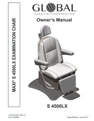
MAXI S <strong>4000</strong> EXAMINATION CHAIR<br />
Owner’s Manual<br />
S <strong>4000</strong><br />
110-015-023 REV D<br />
ECO 202610 Date Effective: June 2016
When contacting Global Surgical Corporation for either Customer Service or Technical<br />
Service, it will be helpful if you have your Customer Identification Number and your<br />
Customer Order Number available. Please take a moment to record these numbers,<br />
which are printed on your invoice, in the spaces below.<br />
Customer Identification Number:<br />
Customer Order Number:<br />
3610 Tree Court Industrial Blvd.<br />
St. Louis, MO 63122, USA<br />
1-800-861-3585<br />
If outside the USA:1-636-861-3388<br />
COPYRIGHT NOTICE<br />
© Copyright 2016, Global Surgical Corporation. No part of this publication may be copied,<br />
photocopied, reproduced, translated, or reduced to any electronic medium or machine-readable<br />
form, in whole or in part, without the prior written consent of Global Surgical Corporation,<br />
3610 Tree Court Industrial Blvd., St. Louis, MO 63122, USA
TABLE OF CONTENTS<br />
Section 1: General Information............................................................................................... 1-1<br />
1.1. Description .................................................................................................................... 1-1<br />
1.2. Optional equipment ....................................................................................................... 1-2<br />
1.3. Unpacking Instructions.................................................................................................. 1-3<br />
Section 2: Installation.............................................................................................................. 2-1<br />
2.1. Installation of <strong>Chair</strong> ....................................................................................................... 2-1<br />
2.2. Installation of Optional Footswitch ................................................................................ 2-2<br />
Section 3 Operation ................................................................................................................. 3-1<br />
3.1. Power On Procedure..................................................................................................... 3-1<br />
3.2. Keypad Functions ......................................................................................................... 3-1<br />
3.3. Headrest........................................................................................................................ 3-4<br />
3.4. Armrest.......................................................................................................................... 3-9<br />
3.5. Footrest ......................................................................................................................... 3-10<br />
3.6. <strong>Chair</strong> Footswitch (Optional) .......................................................................................... 3-11<br />
3.7. Positioning of the Patient .............................................................................................. 3-11<br />
3.8. <strong>Chair</strong> Positions .............................................................................................................. 3-12<br />
3.9. Power Off Procedure..................................................................................................... 3-13<br />
Section 4: Cleaning and Maintenance.................................................................................... 4-1<br />
4.1. Standard Vinyl Upholstery Cleaning and Disinfecting................................................... 4-1<br />
4.2. Plastic Surfaces Cleaning and Disinfecting................................................................... 4-2<br />
4.3. Metal Surfaces Cleaning and Disinfecting..................................................................... 4-2<br />
4.4. Preventive Maintenance................................................................................................ 4-3<br />
Section 5: Troubleshooting..................................................................................................... 5-1<br />
5.1. Troubleshooting............................................................................................................. 5-1<br />
Section 6: Service and Warranty............................................................................................. 6-1<br />
6.1. Warranty Information..................................................................................................... 6-1<br />
6.2 Technical Services Department..................................................................................... 6-2<br />
6.3. Internet Access.............................................................................................................. 6-2<br />
6.4. Service Information ....................................................................................................... 6-2<br />
Section 7: Technical Data........................................................................................................ A-1<br />
Appendix A ........................................................................................................................... A-1<br />
i
SYMBOL DEFINITIONS<br />
This symbol on the product is an attention symbol, alerting the user to read the<br />
Owner’s Manual for important installation, operating instructions or safety information.<br />
This symbol on the product indicates a potential electrical shock hazard, and alerts the user to<br />
read the Owner’s Manual for important safety information.<br />
Symbol indicating an accessible location on or within the chair where there is risk that a body<br />
part may become trapped.<br />
Symbol indicating “not for general waste.” Recycle per the european waste electrical<br />
and electronic equipment (weee) directive.<br />
This symbol indicates earth ground<br />
Equipotentiality<br />
Type B Applied Part<br />
For Professional Use Only<br />
!<br />
WARNING<br />
This symbol indicates a situation in which incorrect handling through disregard of a warning<br />
might result in death or serious personal injury.<br />
!<br />
CAUTION<br />
This symbol indicates a situation in which incorrect handling through disregard of a caution might<br />
result in personal injury or may result in damage to property.<br />
NOTICE<br />
This symbol indicates a message to avoid property damage or additional information to help<br />
complete a procedure.<br />
ii
WARNINGS AND CAUTIONS<br />
!<br />
WARNING<br />
THE SAFETY AND SATISFACTION OF OUR CUSTOMERS AND THEIR<br />
PATIENTS IS THE HIGHEST PRIORITY OF GLOBAL SURGICAL. THE<br />
FOLLOWING SECTIONS OF THIS MANUAL CONTAIN IMPORTANT<br />
INFORMATION REGARDING THE SAFE AND PROPER USE OF THIS<br />
EQUIPMENT, AND SHOULD BE READ THOROUGHLY BY ALl OPERATORS<br />
PRIOR TO THEIR FIRST USE OF THE EQUIPMENT. FAILURE TO READ AND<br />
UNDERSTAND THIS MATERIAL COULD RESULT IN INJURY TO PATIENTS OR<br />
PERSONNEL, OR IN DAMAGE TO THE EQUIPMENT.<br />
We encourage our customers to recycle this product whenever possible. Disposal of this<br />
unit must be performed in accordance with the applicable local environmental regulations.<br />
iii
WARNINGS AND CAUTIONS<br />
!<br />
!<br />
!<br />
!<br />
!<br />
!<br />
!<br />
!<br />
!<br />
WARNING<br />
WARNING<br />
WARNING<br />
WARNING<br />
WARNING<br />
WARNING<br />
WARNING<br />
WARNING<br />
WARNING<br />
WARNING<br />
WARNING<br />
To reduce the risk of injury, the motion of the chair due to autoreturn<br />
and memory positioning can be stopped immediately by<br />
pressing any button on the keypad.<br />
TO HELP PREVENT MISUSE OF THE EXAM CHAIR WHILE PATIENTS ARE LEFT<br />
UNATTENDED, ALWAYS ENGAGE THE SAFETY LOCK BEFORE LEAVING THE<br />
ROOM.<br />
DISCONNECT ALL ELECTRICAL POWER PRIOR TO CLEANING AND<br />
DISINFECTING. RISK OF ELECTRICAL SHOCK RESULTING IN DEATH OR<br />
INJURY IS POSSIBLE IF THE ELECTRICAL POWER IS NOT DISCONNECTED.<br />
NO MODIFICATION OF THIS EQUIPMENT IS ALLOWED.<br />
TO PREVENT RISK OF SHOCK OR INJURY, DO NOT USE OTHER ELECTRICAL<br />
EQUIPMENT ON THE PATIENT WITHOUT FIRST ENSURING PROPER<br />
GROUNDING OF CHAIR.<br />
THE USE OF POWER CORD AND PLUG OTHER THAN THOSE INCLUDED WITH<br />
THE MAXI MAXI S <strong>4000</strong> EXAMINATION CHAIR AND SUPPLIED BY GLOBAL<br />
SURGICAL TM CORPORATION MAY RESULT IN INCREASED EMISSIONS OR<br />
DECREASED IMMUNITY OF THE MAXI S <strong>4000</strong> EXAMINATION CHAIR.<br />
It is highly recommended that the installation of this equipment<br />
be performed by qualified technicians. Installation by<br />
unqualified individuals could result in personal injury.<br />
DO NOT CLEAN ANY SURFACE WITH PETROLEUM-BASED SOLVENTS SUCH<br />
AS ACETONE OR M.E.K. (METHYL ETHYL KETONE). THESE SOLVENTS WILL<br />
REMOVE PAINT AND CAUSE PERMANENT DAMAGE TO VINYL AND PLASTIC<br />
SURFACES. USING THESE SOLVENTS ALSO PRESENTS A DANGER TO<br />
PERSONNEL IF THEY ARE OPENED IN A POORLY VENTILATED ROOM.<br />
TO AVOID THE RISK OF ELECTRIC SHOCK, THIS EQUIPMENT MUST ONLY BE<br />
CONNECTED TO A SUPPLY MAINS WITH PROTECTIVE EARTH (=ground).<br />
CONNECTING EQUIPMENT TO THE MULTIPLE SOCKET-OUTLET EFFECTIVELY<br />
LEADS TO CREATING A Medical Electrical SYSTEM AND THE RESULT CAN<br />
BE A REDUCED LEVEL OF SAFETY. THE ONLY EQUIPMENT INTENDED TO BE<br />
CONNECTED TO THE CHAIR IS THE SOLAR LITE MANUFACTURED BY GLOBAL<br />
SURGICAL CORPORATION.<br />
TO MINIMIZE THE RISKS DUE TO MOVING PARTS AND PINCH POINTS,<br />
ENSURE THE PATIENT IS SEATED AS INTENDED WITH HEAD SUPPORTED BY<br />
THE HEADREST, ARMS SUPPORTED BY THE ARMRESTS AND LEGS<br />
SUPPORTED BY THE CALF REST BEFORE OPERATING THE CHAIR.<br />
OPERATORS SHOULD KEEP THEIR FREE HAND AND THEIR FEET AWAY FROM<br />
THE CHAIR WHILE THE CHAIR IS MOVING.<br />
iv
WARNINGS AND CAUTIONS<br />
!<br />
!<br />
!<br />
!<br />
!<br />
!<br />
!<br />
!<br />
!<br />
WARNING<br />
WARNING<br />
WARNING<br />
CAUTION<br />
CAUTION<br />
CAUTION<br />
CAUTION<br />
CAUTION<br />
CAUTION<br />
THE MAXI S <strong>4000</strong> EXAMINATION CHAIR SHOULD NOT BE USED ADJACENT OR<br />
STACKED WITH OTHER EQUIPMENT AND IF ADJACENT OR STACKED USE Is<br />
necessary, it should be verified that the MAXI S <strong>4000</strong> EXAMINATION<br />
CHAIR OPERATES NORMALLY IN THE CONFIGURATION IN WHICH IT WILL BE<br />
USED.<br />
To prevent risk of injury or risk of damage to the chair, keep all<br />
objects and body parts out from under the chair while the chair<br />
is in motion. Also instruct the patient to minimize movement while<br />
the chair is in motion.<br />
PATIENTS ENTERING OR EXITING THE CHAIR IN A POSITION OTHER THAN THE<br />
HOME/AUTO RETURN POSITION COULD BE INJURED OR COULD CAUSE<br />
DAMAGE TO THE EQUIPMENT.<br />
When used in clinical or residential areas near radio or TV units, this equipment<br />
may be subjected to radio interference. To avoid adverse electromagnetic<br />
effects, do not operate this equipment near RF energy equipment.<br />
To prevent any potential electromagnetic interference, do not use any kind of<br />
cellular phone near the equipment.<br />
This equipment needs special precautions regarding EMC (Electromagnetic<br />
Compatibility) and needs to be installed and put into service according to the<br />
EMC information provided in Appendix A of this manual.<br />
Portable and mobile RF communications equipment can affect medical electrical<br />
equipment.<br />
Replacement parts, such as cables, must be purchased through Global<br />
Surgical TM Corporation to ensure proper compliance requirements. The use of<br />
other cables may affect EMC performance. Unauthorized use of these items will<br />
void warranty and may cause injury to you, others and/or the equipment.<br />
Do not overtighten the adjustment nut or the pins in the upper link will break.<br />
!<br />
CAUTION<br />
Do not use scouring materials such as SCOTCH-BRITE® on vinyl or plastic<br />
surfaces for stubborn stains. These materials will damage these surfaces.<br />
!<br />
!<br />
CAUTION<br />
CAUTION<br />
Should you desire to use other cleaning methods, carefully try them in an inconspicuous<br />
area to determine potential damage to the material. Never use harsh solvents or cleaners<br />
which are intended for industrial applications. To clean stained or soiled areas, a soft<br />
white cloth is recommended. Avoid the use of paper towels.<br />
Cleaning products may be harmful/irritating to your skin, eyes, etc. Use protective gloves<br />
and eye protection. Do not inhale or swallow any cleaning product. Protect<br />
surrounding area/clothing from exposure. Use in a well-ventilated area. Follow all<br />
product manufacturers’ warnings. Naugahyde cannot be held responsible for damage<br />
or injuries resulting from the use or misuse of cleaning products.<br />
v
Section 1<br />
General Information<br />
1.1. Description<br />
Intended Use: The <strong>Maxi</strong> <strong>4000</strong> Examination <strong>Chair</strong> is an active, non-invasive medical device that is intended to support<br />
patients and to assist medical professionals with patient positioning during medical examinations and procedures.<br />
The frequently used functions include recline/incline, lift/lower, rotation lock, safety lock mode, auto return, armrest<br />
adjustment, headrest adjustment and memory. See Section 1.2 for optional equipment.<br />
NOTICE<br />
The <strong>Maxi</strong> <strong>4000</strong> Examination <strong>Chair</strong> is not intended to be used with Intravenous (IV) poles.<br />
The <strong>Maxi</strong> <strong>4000</strong> Examination <strong>Chair</strong> uses a key pad for operation. This key pad is located on either side of the chair. The<br />
chair can be flat reclined, has a 345° rotation, has a seat width of 22” (559 mm) and has a height travel range of 21”-38”<br />
(533-965 mm). There is an adjustable headrest, and the arm rests lay flat when the chair is reclined. The maximum lift/<br />
support is 400 lbs (181 kg).<br />
Table 1-1. <strong>Chair</strong> Specifications<br />
ITEM<br />
SPECIFICATION<br />
Shipping Weight<br />
383 lbs (173 kg)<br />
Base Dimensions<br />
30-1/2” x 38” (775 mm x 965 mm)<br />
Travel Range of Seat Height<br />
21” to 38” (533 mm to 965 mm)<br />
Rotation 345°<br />
<strong>Chair</strong> Seat Angle (Fixed) 5°<br />
Range of <strong>Chair</strong> Back Angle 100° - 180°<br />
<strong>Maxi</strong>mum Lift Capacity<br />
400 lbs (181 kg)<br />
Power Consumption<br />
4 amp<br />
Input Voltage<br />
120v 60hz<br />
Input Voltage with Solarlite<br />
120v 60hz<br />
Mode of Operation<br />
Non-Continuous Operation 10% duty cycle (2 min – 18 min)<br />
Water Resistance<br />
Medical Electrical (ME)<br />
Equipment Classification<br />
ME Equipment Applied Part<br />
Classification<br />
Operation Environment:<br />
• Temperature<br />
• Relative Humidity<br />
• Air Pressure<br />
Storage Environment:<br />
• Temperature<br />
• Relative Humidity<br />
• Air Pressure<br />
IPXO<br />
Class I<br />
Type B<br />
+10° to +40°C (50° to 104°F)<br />
0 to 95%<br />
700 to 1060 kPa<br />
-20° to +60°C (-4° to 140°F)<br />
0 to 95%<br />
700 to 1060 kPa<br />
Regulations / Standards<br />
Conforms to ANSI/AAMI Std ES60601-1,<br />
IEC Stds 60601-1, 60601-1-6 & 62366<br />
Certified to CSA Std C22.2 No. 60601-1<br />
91613<br />
1-1
Section 1<br />
General Information<br />
1.2. Optional Equipment<br />
• S 410003 <strong>Chair</strong> Footswitch<br />
A control located on the floor for the purpose of operating the chair with the foot versus the touch pad panels<br />
on either side of the chair back. This offers a “hands-free” method to positioning the chair.<br />
• S 900112W & S 900114W Solarlite TM<br />
S 900112W Solarlite TM<br />
S 900114W Solarlite TM<br />
A reusable light source manufactured by Global Surgical Corporation intended to be installed on the<br />
MAXI S <strong>4000</strong> Examination <strong>Chair</strong> for the purpose of illuminating the area of interest during medical procedures<br />
and examinations. The S 900112W Solarlite has the power switch on the base. The S 900114W Solarlite has<br />
the power switch on the head.<br />
For instructions on the installation of the Solarlite see “Solarlite S 900 Series Exam Lights Installation Instructions”<br />
Part # 108-008-003<br />
!<br />
WARNING<br />
CONNECTING EQUIPMENT TO THE MULTIPLE-SOCKET OUTLET EFFECTIVELY<br />
LEADS TO CREATING AN Medical Electrical SYSTEM AND THE RESULT CAN<br />
BE A REDUCED LEVEL OF SAFETY. THE ONLY EQUIPMENT INTENDED TO BE<br />
CONNECTED TO THE CHAIR IS THE SOLARLITE MANUFACTURED BY GLOBAL<br />
SURGICAL CORPORATION.<br />
1-2
Section 1<br />
General Information<br />
1.3. Unpacking Instructions<br />
!<br />
!<br />
!<br />
WARNING<br />
WARNING<br />
WARNING<br />
FAILURE TO FOLLOW THESE INSTRUCTIONS WILL RESULT IN DAMAGE TO THIS<br />
CHAIR OR POSSIBLE INJURY (RECEIVER’S RESPONSIBILITY).<br />
It is highly recommended that the installation of this equipment<br />
be performed by qualified technicians. Installation by unqualified<br />
individuals could result in personal injury.<br />
DO NOT LIFT THE CHAIR BY THE ARMS OR HEADREST.<br />
!<br />
WARNING<br />
NOTICE<br />
NOTICE<br />
DO NOT REMOVE THE STRAP OR 2 X 4 WOOD BRACE HOLDING THE SEAT IN<br />
PLACE UNTIL THE CHAIR IS IN IT’S PERMANENT LOCATION.<br />
Check for damage before discarding the shipping material and notify Global<br />
Surgical TM Customer Service if shipping damage is observed.<br />
Leave the chair on the wooden skid until qualified technician begins installation.<br />
1. Inspect all packaging for any visible signs of damage.<br />
2. Make a notation on the delivery receipt if the packaging was previously opened and check the package for<br />
proper content.<br />
DO NOT lift by the arms<br />
DO NOT lift by the headrest<br />
Lift under seat here<br />
Lift under back here<br />
DO NOT REMOVE this strap<br />
! WARNING or 2 x 4 wooden brace until<br />
chair is in its permanent<br />
location.<br />
!<br />
DO NOT REMOVE<br />
UNTIL CHAIR IS PLACED IN ITS<br />
PERMANENT LOCATION<br />
Figure 1-1 Unpacking<br />
1-3
!<br />
WARNING<br />
DO NOT REMOVE THE STRAP OR 2 X 4 WOOD BRACE HOLDING THE SEAT IN<br />
PLACE UNTIL THE CHAIR IS IN ITS PERMANENT LOCATION.<br />
3. Remove the fasteners along the bottom of the packaging that secure the chair to the wooden pallet.<br />
4. Lift the chair off of the skid by grasping its back and seat framework. Do not lift by the arms or headrest.<br />
See Figure 1-1<br />
5. When chair is in its permanent position cut and remove strap.<br />
6. Plug the chair into the wall once the chair is placed in its permanent location.<br />
7. Press the “SEAT UP” button to lift the chair off of the 2 x 4 wood brace. Be sure to lift the chair high enough<br />
so the bottom of the calf rest is above the 2 x 4 wood brace.<br />
8. Slide the 2 x 4 wood brace off the chair base and set aside.<br />
9. All shipping materials should be retained until it has been determined that the unit was not damaged during<br />
shipment.<br />
If damage is discovered, completed the following:<br />
• Do not refuse shipment.<br />
• Make a notation on the delivery receipt, and inspect the carton for damage.<br />
• Take pictures of damage to the equipment, and to the packaging (if evident).<br />
• If damage is discovered leave in original container and request immediate inspection from the carrier.<br />
• Contact the Global Surgical Customer Service Department at 1-800-861-3585.<br />
• If the product is damaged electrically or mechanically and in the event the original packing materials are no<br />
longer available, contact Global Surgical Customer Services Department.<br />
• Refer to Section 6 of this manual regarding service and warranty and proceed as instructed.<br />
1-4
Section 2<br />
Installation<br />
!<br />
WARNING<br />
It is highly recommended that the installation of this equipment<br />
be performed by qualified technicians. Installation by<br />
unqualified individuals could result in personal injury.<br />
2.1. Installation of the <strong>Chair</strong><br />
Installation of the chair is intended to be completed by qualified Global Surgical technicians. The end user should not<br />
attempt to move the chair off the wooden skid and/or install the chair as there is risk of personal injury as well as damage<br />
to the chair.<br />
Refer to Table 1-1 and Figure 2-1 for clearance requirements and determine an appropriate installation site. The<br />
installation should be close enough to a 115 VAC 20A wall receptacle to be reached by the 13 foot (4 m) power cord.<br />
When planning an installation site, ensure the base is positioned where accessibility is not hindered by these limits. Also<br />
ensure the floor is level. An uneven floor may allow the chair to wobble which is undesirable during use with the patient.<br />
38”<br />
(965 mm)<br />
79”<br />
(2007 mm)<br />
52.5”<br />
(1334 mm)<br />
47”<br />
(1194 mm)<br />
21”- 38”<br />
(553 mm - 965 mm)<br />
Figure 2-1 Overall Sideview Dimensions<br />
2-1
Section 2<br />
Installation<br />
38”<br />
(965 mm)<br />
17-5/8”<br />
(448 mm)<br />
23.5”<br />
(597 mm)<br />
30-1/2”<br />
(775 mm)<br />
22”<br />
( 559 mm)<br />
30.2”<br />
( 767 mm)<br />
Figure 2-2 Overall Top View Dimensions<br />
NOTICE<br />
Do not position the chair so that it is difficult to disconnect from the power supply.<br />
2.2. Installation of the Optional Footswitch<br />
The <strong>Maxi</strong> <strong>4000</strong> Examination <strong>Chair</strong> has an optional footswitch that works in conjunction with the keypad located on both<br />
sides of the chair back. To install the optional footswitch:<br />
1. Locate the power entry module on the base of the chair<br />
2. Unscrew the protective dust cap<br />
3. Insert the footswitch plug using the keyways to line up the pins. Secure by screwing the coupling ring onto the<br />
receptacle.<br />
2-2
Section 3<br />
NOTICE<br />
Operation<br />
Ensure the parts and accessories are properly installed per Section 2 before operating the<br />
chair.<br />
3.1. Power On Procedure<br />
1. Plug in the chair to initiate operation of the chair.<br />
3.2. Keypad Functions<br />
!<br />
WARNING<br />
To reduce the risk of injury, the motion of the chair due to auto-return<br />
and memory positioning can be stopped immediately by pressing any<br />
BUTTON on the keypad.<br />
LOCK<br />
Rotation Lock/Safety Lock<br />
Back Up<br />
BACK<br />
Back Down<br />
Seat Up<br />
SEAT<br />
Seat Down<br />
MEMORY<br />
Memory Position<br />
HOME<br />
Auto Return (Home)<br />
Figure 3-1 Keypad Rotation<br />
3-1
Section 3<br />
!<br />
WARNING<br />
3.2.1. Rotation Lock/Safety Lock<br />
Operation<br />
TO HELP PREVENT MISUSE OF THE EXAM CHAIR WHILE PATIENTS ARE LEFT<br />
UNATTENDED, ALWAYS ENGAGE THE SAFETY LOCK BEFORE LEAVING THE<br />
ROOM.<br />
This button controls two functions: rotation lock and safety lock mode. The rotation lock is the primary function. The chair<br />
may be manually rotated 345° on its base. The chair is normally in the locked position. To unlock the brake, press the<br />
button for 1 second. Once unlocked, the chair will be free to rotate to the desired position. The button can be pressed for<br />
1 second again to set the brake or the chair will automatically secure the rotational lock after a 12 second delay.<br />
The safety lock mode is also activated using this button. This function sets the rotation lock on the chair and disables<br />
the key pad controls and optional footswitch controls. While in safety lock mode, the padlock indicator light will be lit. To<br />
activate the safety lock mode, press the lock button and hold for at least 3 seconds. The padlock indicator light will light<br />
up once the safety lock mode is entered. To exit safety lock mode, press the lock button again and hold for at least 3<br />
seconds. The padlock indicator light will extinguish once the safety lock mode is exited.<br />
3.2.2. Backrest Up<br />
This button moves the chair back from a reclined position to an upright position. The chair back will move up for as long<br />
as the button is pressed until it reaches its travel limit of 80° above horizontal.<br />
3.2.3. Backrest Down<br />
This button moves the chair back from an upright position to a reclined position. The back will move down for as long as<br />
the button is pressed until it reaches its travel limit of horizontal.<br />
3.2.4. Seat Up<br />
This button moves the chair up in elevation. The chair will move up for as long as the button is pressed until it reaches its<br />
travel limit of 38” from the floor. If the rotation lock is unlocked while the chair is moving up, the seat will pause for one<br />
second then resume moving up.<br />
3-2
Section 3<br />
Operation<br />
3.2.5. Seat Down<br />
This button moves the chair down in elevation. The chair will move down as long as the button is pressed until it<br />
reaches its travel limit of 21” from the floor.<br />
3.2.6. Auto Return (Home)<br />
The Auto Return button is used to move the seat to its lowest elevation and to move the backrest to 80° above<br />
horizontal. This is the ideal position for patients entering and exiting the chair. When the Auto Return button is pressed<br />
for 1 second then released, the chair moves until the auto return position is reached.<br />
3.2.7. User Programmable Memory Position<br />
The MAXI S <strong>4000</strong> can store one memory position. To store the current chair position into memory, press and hold the<br />
memory button for 3 seconds. A 1 second audible beep will confirm the memory position storage. Once the memory<br />
position has been stored, it can be recalled by pressing for 1 second then releasing the memory button. The chair will<br />
move until the stored position has been reached. When recalling a stored position, be careful not to hold the memory<br />
button too long because pressing the button for 3 seconds or longer will store a new memory position.<br />
3-3
Section 3<br />
Operation<br />
3.2.8. Pinch Points<br />
!<br />
!<br />
!<br />
WARNING<br />
WARNING<br />
WARNING<br />
TO MINIMIZE THE RISKS DUE TO MOVING PARTS AND PINCH POINTS, ENSURE<br />
THE PATIENT IS SEATED AS INTENDED WITH HEAD SUPPORTED BY THE<br />
HEADREST, ARMS SUPPORTED BY THE ARMRESTS AND LEGS SUPPORTED BY<br />
THE CALF REST BEFORE OPERATING THE CHAIR. OPERATORS SHOULD KEEP<br />
THEIR FREE HAND AND THEIR FEET AWAY FROM THE CHAIR WHILE THE CHAIR<br />
IS MOVING.<br />
TO PREVENT RISK OF INJURY OR RISK OF DAMAGE TO THE CHAIR, KEEP ALL<br />
OBJECTS AND BODY PARTS OUT FROM UNDER THE CHAIR WHILE THE CHAIR<br />
IS IN MOTION. ALSO INSTRUCT THE PATIENT TO MINIMIZE MOVEMENT WHILE<br />
THE CHAIR IS IN MOTION.<br />
To reduce the risk of injury, the motion of the chair due to<br />
auto-return and memory positioning can be stopped immediately<br />
by pressing any button on the keypad.<br />
Specific areas on the chair may have a risk of injury due to pinch points. To minimize these risks be mindful of body part<br />
locations while the chair is moving and do not leave patient unattended while chair is in motion. See Figure 3-2 for<br />
potential pinch point locations.<br />
Figure 3-2 Pinch Point Locations<br />
3-4
Section 3<br />
3.3. Headrest<br />
Operation<br />
Intended Use:<br />
To support a patient’s head during medical examination or procedure. It is adjustable to accommodate different patients’<br />
support needs.<br />
3.3.1. Articulating Headrest<br />
The Multi-Position Adjustable Headrest is positioned by manipulating the pivoting arm assembly mounted on the back of<br />
the chair. The headrest mechanism is restrained by a movable handle which is part of the assembly. To reposition the<br />
headrest, the following procedures apply. Refer to Figure 3-3.<br />
Headrest Positioning<br />
1. Grasp the handle and pull outward and upward (this releases the arm assembly) while steadying the<br />
headrest with the other hand.<br />
2. Move the handle forward or backward to obtain the optimum position for the patient’s head.<br />
3. Lock the headrest into position by grasping the handle and the adjoining arm between your thumb and<br />
fingers and squeezing tightly. The handle will snap into the restraining position.<br />
3<br />
2<br />
1<br />
Figure 3-3 Headrest Adjustment<br />
3-5
Section 3<br />
Operation<br />
! CAUTION Do not over tighten the adjustment nut or the pins in the upper link will break.<br />
Tightening of Friction Lock<br />
Occasionally the headrest may need to be tightened. The headrest mechanism relies on friction to maintain a secure<br />
position. To tighten this adjustment, refer to Figure 3-4 and proceed as follows:<br />
1. Unlock the headrest and move it to the extreme upward and forward position. Leave the headrest unlocked.<br />
2. Loosen the Set Screw a couple of turns, with a 3/16 Hex Wrench.<br />
3. Using a 3/8” hex wrench tighten the adjustment nut until it stops. Unlock the handle and turn the<br />
adjustment nut 1/8 of a turn and re-lock the handle. If headrest is not at the desired tension, repeat the process by<br />
unlocking the handle and adjusting another 1/8 turn.<br />
4. If the handle is too hard to lock into place, loosen the nut and try the handle again.<br />
5. When the adjustment is correct use one hand on the back of the chair grab the upper link and pull the headrest<br />
backward towards you. If the headrest does not move then the adjustment nut is secure.<br />
6. Re-tighten the set screw using a 3/16” hex wrench.<br />
NOTICE<br />
This is a user adjustment and as such is not covered by the warranty.<br />
Head Rest<br />
Upper Link<br />
Headrest Handle<br />
Handle in locked<br />
position<br />
Handle in un-locked<br />
position<br />
Adjustment<br />
Nut<br />
Set Screw<br />
Figure 3-4 Tightening the Friction Lock<br />
3-6
Section 3<br />
Operation<br />
3.3.2. Single Handed Headrest Adjustment<br />
The headrest is adjustable to accommodate every patient. To attain an ideal headrest position, follow the steps listed<br />
below.<br />
1. Grasp the handle and pull upward on the release bar with one hand to unlock the arm assembly.<br />
2. While squeezing the release bar, maneuver the headrest to the desired position then release the bar. The headrest is<br />
now locked in place.<br />
Release Bar<br />
Figure 3-5 Single Handed Headrest Adjustment<br />
3-7
Section 3<br />
Operation<br />
Single Handed Headrest Positions<br />
Lowest Position<br />
Mid-Range Position<br />
Farthest Position<br />
Figure 3-6 Single Handed Headrest Positions<br />
3-8
Section 3<br />
Operation<br />
3.3.3. Sliding Headrest Adjustment<br />
The sliding headrest is adjusted by manipulating the sliding plate assembly mounted on the back of the chair. The sliding<br />
headrest provides excellent support for the patient’s head and can be adjusted for patients of various heights. Refer to<br />
Figure 3-7 and perform the following steps to correctly position the headrest for each patient:<br />
1. While steadying the headrest with one hand, grasp the knob and turn counter-clockwise to release tension on the<br />
sliding headrest.<br />
2. Slide the headrest up or down to obtain the optimum position for the patient’s head.<br />
3. Turn the knob clockwise to increase tension and lock the headrest in place.<br />
2<br />
1 3<br />
Figure 3-7 Sliding Headrest Adjustment<br />
3-9
Section 3<br />
Operation<br />
3.4. Armrest<br />
Intended use:<br />
To support a patient’s arms during medical examination or procedure. Armrests can be positioned to aid patient entry or<br />
exit from chair.<br />
To raise the armrest, lift upward on the front of the armrest until it reaches its limit of travel, as shown in Figure 3-8. When<br />
reclined, the armrests lay flat.<br />
Figure 3-8 Armrest positions<br />
3-10
Section 3<br />
Operation<br />
3.5. Footrest<br />
Intended use:<br />
To provide a place to rest feet during a medical examination or procedure. Footrests can be positioned to aid patient<br />
entry or exit from chair.<br />
To raise the footrest, fold towards the calf rest. To lower the footrest into position, fold the footrest towards the floor refer<br />
to Figure 3-9.<br />
Figure 3-9 Footrest Positions<br />
3-11
Section 3<br />
Operation<br />
3.6. <strong>Chair</strong> Footswitch (optional)<br />
BACK DOWN<br />
SEAT UP<br />
BACK UP<br />
SEAT DOWN<br />
Figure 3-10 Footswitch controls<br />
The Footswitch is an ergonomically designed modular system for easy hands-free control of the chair.<br />
3.7. Positioning of patient:<br />
Patients should be allowed to enter or exit the chair only while the rotation lock is applied and the seat and back are in the<br />
Auto Return (Home) position. See Figure 3-11 Position the footrest down to use as a step for patients as they enter or<br />
exit the chair. For some patients, it may be helpful to move the armrests up and out of the way. See Section 3.8.<br />
The patient should be sitting in the chair with back firmly against the chair’s backrest and legs on the leg rest before<br />
bringing the chair into operation.<br />
!<br />
WARNING<br />
PATIENTS ENTERING OR EXITING THE CHAIR IN A POSITION OTHER THAN THE<br />
HOME/AUTO RETURN POSITION COULD BE INJURED OR COULD CAUSE<br />
DAMAGE TO THE EQUIPMENT.<br />
!<br />
WARNING<br />
To minimize the risks due to moving parts, ensure the patient is<br />
seated as intended with head supported by the headrest, arms<br />
supported by the armrests and legs supported by the calf rest<br />
before operating the chair. OPERATORS SHOULD KEEP THEIR FREE<br />
HAND AND THEIR FEET AWAY FROM THE CHAIR WHILE THE CHAIR IS MOVING.<br />
3-12
Section 3<br />
3.8. <strong>Chair</strong> Positions<br />
Operation<br />
The chair back is adjustable from Home/ Auto Return seating position to completely reclined. The seat is adjustable from<br />
a height of 21” (533 mm) to 38” (965 mm).<br />
Figure 3-11 <strong>Chair</strong> in Auto Return (Home) Position<br />
3.9. Power Off Procedure<br />
Figure 3-12 <strong>Chair</strong> in Recline Position<br />
Unplug the chair to safely terminate the operation of the medical equipment.<br />
3-13
Section 4<br />
Cleaning and Maintenance<br />
!<br />
WARNING<br />
DISCONNECT ALL ELECTRICAL POWER PRIOR TO CLEANING AND<br />
DISINFECTING. RISK OF ELECTRICAL SHOCK RESULTING IN DEATH OR<br />
INJURY IS POSSIBLE IF THE ELECTRICAL POWER IS NOT DISCONNECTED.<br />
!<br />
WARNING<br />
DO NOT CLEAN ANY SURFACE WITH PETROLEUM-BASED SOLVENTS SUCH<br />
AS ACETONE OR M.E.K. (METHYL ETHYL KETONE). THESE SOLVENTS WILL<br />
REMOVE PAINT AND CAUSE PERMANENT DAMAGE TO VINYL AND PLASTIC<br />
SURFACES. USING THESE SOLVENTS ALSO PRESENTS A DANGER TO<br />
PERSONNEL IF THEY ARE OPENED IN A POORLY VENTILATED ROOM.<br />
!<br />
CAUTION<br />
DO NOT Use scouring materials such as SCOTCH-BRITE® on vinyl or plastic<br />
surfaces for stubborn stains. These materials will damage these surfaces.<br />
NOTICE<br />
Clean and disinfect after every patient according to CDC and OSHA requirements<br />
for non-critical devices.<br />
4.1. Standard Vinyl Upholstery Cleaning and Disinfecting<br />
Cleaning<br />
While staining and soiling exposures are common to upholstery fabrics, most stain and soiling may be removed by using<br />
the simple cleaning methods that follow:<br />
For Light soiling:<br />
1. A solution of 10% household liquid dish soap (pH~9) with warm water applied with a soft damp cloth will remove<br />
most soiling.<br />
2. If necessary, use a solution of liquid cleanser and water applied with a soft bristle brush. Wipe away the residue with a<br />
water-dampened cloth.<br />
For Heavier soiling not solved by above method:<br />
1. Dampen a soft white cloth with lighter fluid (naphtha) and rub gently.<br />
2. Rinse with a water-dampened cloth.<br />
!<br />
WARNING<br />
Use extreme caution with this method. Complete only in a<br />
well-ventilated area and away from any open flame. Do Not use this<br />
method in an oxygen rich environment.<br />
NOTICE<br />
You should try this method on an inconspicuous spot before using it on the original<br />
stain/soiling.<br />
4-1
Section 4<br />
Cleaning and Maintenance<br />
For the most difficult stains not removed by the light or heavier soiled methods:<br />
1. Dampen a soft white cloth with a solution of household bleach (sodium hypochlorite); 10% bleach, 90% water and<br />
rub gently.<br />
2. Rinse with a water-dampened cloth to remove bleach concentration.<br />
3. If necessary, allow a 1:10 diluted bleach solution to puddle on the affected area or apply with a soaked cloth for<br />
approximately 30 minutes. Rinse with a water-dampened cloth to remove any remaining bleach concentration.<br />
NOTICE<br />
You should try this method on an inconspicuous spot before using it on the original<br />
stain/soiling.<br />
NOTICE<br />
To restore luster, a light coat of spray furniture wax can be used. Apply for 30 seconds<br />
and follow with a light buffing using a clean white cloth.<br />
!<br />
CAUTION<br />
Should you desire to use other cleaning methods, carefully try them in an inconspicuous<br />
area to determine potential damage to the material. Never use harsh solvents or cleaners<br />
which are intended for industrial applications. To clean stained or soiled areas, a soft<br />
white cloth is recommended. Avoid the use of paper towels.<br />
!<br />
CAUTION<br />
Cleaning products may be harmful/irritating to your skin, eyes, etc. Use protective gloves<br />
and eye protection. Do not inhale or swallow any cleaning product. Protect<br />
surrounding area/clothing from exposure. Use in a well-ventilated area. Follow all<br />
product manufacturers’ warnings. Global cannot be held responsible for damage<br />
or injuries resulting from the use or misuse of cleaning products.<br />
Disinfecting<br />
1. Disinfect the upholstery with products containing sodium hypochlorite (common household bleach) diluted 1:10.<br />
Follow the instructions given by the manufacturer of the disinfectant solution.<br />
2. Use caution when cleaning and disinfecting around stitching and controls.<br />
3. Do not allow excessive moisture or liquids to come in direct contact with the chair.<br />
4.2. Plastic Surface Cleaning and Disinfecting<br />
1. Plastic surfaces can be cleaned by using a mild soap and water solution and a clean, soft cloth. To treat stains,<br />
use a soft bristle brush. Use a cloth dampened with water to remove any remaining cleaner. Dry the<br />
plastic surface with a soft, lint-free cloth. Do not use cleaning agents that are not permitted for use with plastics,<br />
i.e., ammonia, acetone, salty acids (HCI), etc.<br />
2. Use caution when cleaning and disinfecting around controls.<br />
3. Use any disinfectant agents which are commonly applied while disinfecting surfaces of electric medical equipment.<br />
Such disinfectant agents are usually in the form of sprays or damp cloths.<br />
4. Follow the instructions given by the manufacturer of the disinfectant solution.<br />
4.3. Metal Surface Cleaning and Disinfecting<br />
1. Metal surfaces should be cleaned with a cloth dampened (not wet) with water.<br />
2. Use any disinfectant agents which are commonly applied while disinfecting surfaces of electric medical equipment.<br />
Such disinfectant agents are usually in the form of sprays or damp cloths.<br />
3. Follow the instructions given by the manufacturer of the disinfectant solution.<br />
4-2
Section 4<br />
Cleaning and Maintenance<br />
4.4. Preventive Maintenance:<br />
The chair is maintenance free; however, it must be periodically cleaned. An established routine of cleaning will alleviate<br />
most potential problems. If repair becomes necessary, it is recommended that the Global Surgical TM Technical Services<br />
Department be contacted. Refer to Section 6 of this manual for applicable telephone numbers or visit Global Surgical TM<br />
on the World Wide Web at: http://www.globalsurgical.com.<br />
Occasionally the Articulating headrest may need to be tightened. The headrest mechanism relies on friction to maintain a<br />
secure position. To tighten this adjustment, refer to Figure 3-4 on page 3-6.<br />
NOTICE<br />
This is a user adjustment and as such is not covered by the warranty.<br />
Storage Conditions:<br />
The chair is stationary and not intended to be moved after installation. It should always be stored upright and away from<br />
water.<br />
The storage environment is:<br />
• Temperature: -20° to +60°C (-4° to 140°F)<br />
• Relative Humidity: 0 to 95%<br />
• Air Pressure: 700 to 1060 kPa<br />
4-3
Section 5<br />
Troubleshooting<br />
5.1. Troubleshooting<br />
Table 5-1. (below) lists some symptoms, possible causes, and solutions.<br />
Contact Global Surgical’s Technical Services for any issues with the chair to include audible alarms<br />
Table 5-1. Troubleshooting Guide<br />
Symptoms<br />
Solutions<br />
Ensure that the Power Cord is properly connected.<br />
No Power to the chair /<br />
keypad does not work<br />
Verify building circuit breaker is not tripped, or that another device works in<br />
the same outlet.<br />
Verify the “Safety Lock” cannot be engaged.<br />
If footswitch has been installed make sure that the footswitch plug is<br />
securely seated in the chair port. If a fatal error has occurred due to a poor<br />
connection proceed with the fatal error reset listed below.<br />
After the chair has run through<br />
several cycles of up and down<br />
the motor fails to work<br />
Let the motor rest for 18 minutes before trying to use the chair again.<br />
The movement of the chair<br />
does not match the key<br />
pressed.<br />
The connections to the chair are incorrect. Contact Technical Services.<br />
A 200 millisecond beep followed by a 200 millisecond pause indicates a<br />
lost chair position. Push the home button, and the chair should reset itself.<br />
If the chair does not reset, proceed with the fatal error reset listed below.<br />
Acoustic warning signal heard<br />
• Fatal error reset – Push the back up and back down buttons<br />
simultaneously for >5 seconds to reset system to factory defaults, and then<br />
press the Auto Return button to reinitialize the system.<br />
A long continuous beep indicates the chair is in fatal error mode. Follow the<br />
fatal error reset instructions listed above. If chair resumes operation, the<br />
alarm was a false error. If it does not resume operation, contact technical<br />
services<br />
A 5 second beep followed by no-beep indicates the chair is<br />
over-heating. Let the motor rest for 18 minutes before trying to use the chair<br />
again.<br />
5-1
Section 6<br />
Service and Warranty<br />
6.1. Warranty Information<br />
Global Surgical Corporation warranty information is located at:<br />
http://www.globalsurgical.com/warranty.html<br />
SMR Cabinet and <strong>Chair</strong> Warranty<br />
SMR cabinets, chairs, and associated accessories include a one-year warranty from defects, which covers<br />
parts and labor.<br />
Except as set forth in this Limited One – Year Warranty, Global Surgical Corporation (the “Company”) hereby<br />
warrants that each SMR (ENT cabinets, exam chairs, and stools) product manufactured and sold by the<br />
company (“Product”) shall be free from defects in materials and workmanship under normal use and service<br />
for one year from date of invoice. This warranty is non-transferable and is valid only with respect to the original<br />
purchaser of the Product. The Company’s obligation under this warranty shall be limited to repairing or replacing,<br />
at the Company’s facility and at the Company’s expense, any parts or components that are demonstrated<br />
to be defective. The purchaser shall be responsible for shipment of the Product to and from the Company’s<br />
facility at 3610 Tree Court Industrial Boulevard, St. Louis, Missouri,63122, Attention: Technical Service, or such<br />
other facility as the Company may otherwise designate.<br />
Under certain circumstances which are pre-approved by the Company, necessary repairs may be made at the<br />
purchaser’s facility. A return authorization is required before returning any Product for warranty service by calling<br />
1-800-861-3610 or 636-861-3388.<br />
This warranty shall be void and of no effect: (1) if the Product is damaged due to misuse, use in a manner<br />
other than pursuant to the instructions for the use of the Product, abuse, physical mishandling or natural<br />
causes such as flood, fire, earthquake, or other perils, as determined by the Company, or (II) if any repairs or<br />
replacements are made by persons unauthorized by the Company to perform such services.<br />
The warranties set forth herein are in lieu of any and all other warranties, expressed or implied, including,<br />
without limitation, warranties of merchantability and fitness for a particular purpose. Purchaser’s rights thereunder<br />
are granted in lieu of any other rights purchaser may have and purchaser hereby waives all other rights,<br />
warranties, remedies or guarantees whatsoever with respect to the product. The Company shall not be liable<br />
for any third parties with respect to the product or its performance. Further, the Company shall not be liable for,<br />
and purchaser hereby releases the Company from, any direct or indirect, consequential, special, and incidental<br />
or punitive damages with respect to the product. In no event shall the Company be liable for any breach of<br />
warranty or other claim in an amount exceeding the purchase price of the product.<br />
This warranty applies to the U.S. and Canada only.<br />
For International warranty information: Email: international@globalsurgical.com<br />
Phone: 1-636-861-3388, Fax: 1-636-861-2969<br />
6-1
Section 6<br />
Service and Warranty<br />
6.2 Technical Services Department<br />
When contacting our Technical Services Department, you will be served by highly knowledgeable representatives in an<br />
efficient manner. If service is required at your location, a skilled technician or sales representive will be dispatched within<br />
24 hours.<br />
If you have questions that are not covered in this manual, please call the Global Surgical Technical Services Department<br />
as listed below:<br />
Toll Free Number: 1-800-861-3610<br />
Technical Services Representatives: 1-636-861-3388<br />
Fax Number: 1-636-861-5284<br />
Email:<br />
techservice@globalsurgical.com<br />
The staffing hours for the Global Surgical Technical Services Department are Monday through Friday from 8:00 a.m. to<br />
5:00 p.m. Central Standard Time.<br />
6.3. Internet Access<br />
The Global Surgical Technical Services website has information about additional products and services and can be<br />
reached by using the online at: http://www.globalsurgical.com.<br />
6.4. Service Information<br />
In the event of any malfunction, you should immediately contact the Global Surgical Technical Services Department for assistance.<br />
A Customer Identification Number and Customer Order Number will be needed when contacting the Technical<br />
Services Department. These numbers are printed on your invoice. To save time in the event service is needed, record<br />
these numbers in the spaces provided in the front of this manual.<br />
A Return Material Authorization (RMA) number must be obtained from the Global Surgical Technical Services<br />
Department prior to returning a product for repair. The following information must accompany all returned units:<br />
1. Your name, address, and telephone number<br />
2. The RMA number<br />
3. A description of the problem<br />
Ship or return the product to:<br />
Global Surgical Corporation<br />
3610 Tree Court Industrial Blvd.<br />
St. Louis, MO 63122<br />
Attention: Technical Services Department<br />
6-2
Section 7<br />
Technical Data<br />
Appendix A<br />
Guidence an manufacturer’s declaration<br />
Appendix A-1 Electromagnectic emissions....................................................................A-1<br />
Appendix A-2 Electromagnetic immunity.......................................................................A-3<br />
Appendix A-3 Recommended separation distances between portable and mobile RF<br />
communications equipment and the MAXI S <strong>4000</strong> Examination....................................A-6<br />
!<br />
WARNING<br />
THE USE OF POWER CORD AND PLUG OTHER THAN THOSE INCLUDED WITH<br />
THE MAXI S <strong>4000</strong> EXAMINATION CHAIR AND SUPPLIED BY GLOBAL<br />
SURGICAL CORPORATION MAY RESULT IN INCREASED EMISSIONS OR<br />
DECREASED IMMUNITY OF THE MAXI S <strong>4000</strong> EXAMINATION CHAIR.<br />
!<br />
WARNING<br />
THE MAXI S <strong>4000</strong> EXAMINATION CHAIR SHOULD NOT BE USED ADJACENT OR<br />
STACKED WITH OTHER EQUIPMENT AND IF ADJACENT OR STACKED USE Is<br />
necessary, it should be verified that the MAXI S <strong>4000</strong> EXAMINATION<br />
CHAIR OPERATES NORMALLY IN THE CONFIGERATION IN WHICH IT WILL BE<br />
USED.<br />
!<br />
CAUTION<br />
When used in clinical or residential areas near radio or TV units, this equipment<br />
may be subjected to radio interference. To avoid adverse electromagnetic<br />
effects, do not operate this equipment near RF energy equipment.<br />
!<br />
CAUTION<br />
To prevent any potential electromagnetic interference, do not use any kind of<br />
cellular phone near the equipment.<br />
!<br />
CAUTION<br />
This equipment needs special precautions regarding EMC (Electromagnetic<br />
Compatibility) and needs to be installed and put into service according to the<br />
EMC information provided in Appendix A of this manual.<br />
!<br />
CAUTION<br />
Replacement parts, such as cables, must be purchased through Global<br />
Surgical Corporation to ensure proper compliance requirements. The use of<br />
other cables may affect EMC performance. Unauthorized use of these items will<br />
void warranty and may cause injury to you, others and/or the equipment.<br />
!<br />
CAUTION<br />
Portable and mobile RF communications equipment can affect medical electrical<br />
equipment.<br />
A-1
Section 7<br />
Technical Data<br />
Appendix A-1<br />
Guidance and manufacturer’s declaration – electromagnetic emissions<br />
The MAXI S <strong>4000</strong> Examination <strong>Chair</strong> is intended for use in the electromagnetic environment specified below.<br />
The customer or the user of MAXI S <strong>4000</strong> Examination <strong>Chair</strong> should assure that it is used in such an<br />
environment.<br />
Emissions Test Compliance Electromagnetic environment -<br />
guidance<br />
RF emissions<br />
CISPR 11<br />
RF emissions<br />
CISPR 11<br />
Harmonic emissions<br />
IEC 61000-3-2<br />
Group 1<br />
Class A<br />
Class A<br />
The MAXI S <strong>4000</strong> Examination<br />
<strong>Chair</strong> uses RF energy only for its<br />
internal function. Therefore, its RF<br />
emissions are very low and are not<br />
likely to cause any interference in<br />
nearby electronic equipment.<br />
The MAXI S <strong>4000</strong> Examination<br />
<strong>Chair</strong> is suitable for use in all<br />
establishments other than domestic,<br />
and may be used in domestic<br />
establishments and those directly<br />
connected to the public low-voltage<br />
power supply network that supplies<br />
buildings used for domestic<br />
purposes, provided the following<br />
warning is heeded:<br />
Voltage fluctuations/flicker<br />
emissions<br />
IEC 61000-3-3<br />
Complies<br />
Warning: This system is intended<br />
for use by healthcare professionals<br />
only. This system may cause<br />
radio interference or may disrupt<br />
the operation of nearby equipment.<br />
It may be necessary to take mitigation<br />
measures, such as re-orienting<br />
or relocating MAXI S <strong>4000</strong><br />
Examination <strong>Chair</strong> or shielding the<br />
location.<br />
A-2
Section 7<br />
Technical Data<br />
Appendix A-2<br />
Guidance and manufacturer’s declaration – electromagnetic immunity<br />
The MAXI S <strong>4000</strong> Examination <strong>Chair</strong> is intended for use in the electromagnetic environment specified below.<br />
The customer or the user of the MAXI S <strong>4000</strong> Examination <strong>Chair</strong> should assure that it is used in such an<br />
environment.<br />
Electromagnetic<br />
Immunity Test IEC 60601 test level Compliance level<br />
environment - guidance<br />
Electrostatic discharge<br />
(ESD)<br />
IEC 61000-4-2<br />
Electrical fast transient/<br />
burst<br />
IEC 61000-4-4<br />
± 6 kV contact<br />
± 8 kV air<br />
± 2 kV for power supply<br />
lines<br />
± 1 kV for input/output<br />
lines<br />
± 6 kV contact<br />
± 8 kV air<br />
± 2 kV for power supply<br />
lines<br />
± 1 kV for input/output<br />
lines<br />
Floors should be wood,<br />
concrete, or ceramic tile. If<br />
floors are covered with synthetic<br />
material, the relative<br />
humidity should be at least<br />
30%.<br />
Mains power quality should be<br />
that of a typical commercial or<br />
hospital environment.<br />
Surge<br />
IEC 61000-4-5<br />
± 1 kV line(s) to line(s)<br />
± 2 kV line(s) to earth<br />
± 1 kV line(s) to line(s)<br />
± 2 kV line(s) to earth<br />
Mains power quality should<br />
be that of a typical<br />
commercial or hospital<br />
environment.<br />
Voltage dips, short<br />
interruptions and voltage<br />
variations on power<br />
supply input lines<br />
IEC 61000-4-11<br />
95% dip in U T<br />
)<br />
for 0,5 cycle<br />
40 % U T<br />
(60% dip in U T<br />
)<br />
for 5 cycles<br />
70 % U T<br />
(30% dip in U T<br />
)<br />
for 25 cycles<br />
95% dip in U T<br />
)<br />
for 5 s<br />
95% dip in U T<br />
)<br />
for 0,5 cycle<br />
40 % U T<br />
(60% dip in U T<br />
)<br />
for 5 cycles<br />
70 % U T<br />
(30% dip in U T<br />
)<br />
for 25 cycles<br />
95% dip in U T<br />
)<br />
for 5 s<br />
Mains power quality should<br />
be that of a typical commercial<br />
or hospital environment. If<br />
the user of the MAXI S <strong>4000</strong><br />
Examination <strong>Chair</strong> requires<br />
continued operation during<br />
power mains interruptions,<br />
it is recommended that the<br />
MAXI S <strong>4000</strong><br />
Examination <strong>Chair</strong> be<br />
powered from an<br />
uninterruptible power supply<br />
or a battery.<br />
Power frequency (50/60<br />
Hz) magnetic field<br />
IEC 61000-4-8<br />
3A/m 3A/m Power frequency magnetic<br />
fields should be at levels<br />
characteristic of a typical<br />
location in a typical commercial<br />
or hospital environment.<br />
NOTE: UT is the a.c. mains voltage prior to application of the test level.<br />
A-3
Section 7<br />
Technical Data<br />
Appendix A-2<br />
Guidance and manufacturer’s declaration – electromagnetic immunity<br />
The MAXI S <strong>4000</strong> Examination <strong>Chair</strong> is intended for use in the electromagnetic environment specified below.<br />
The customer or the user of the MAXI S <strong>4000</strong> Examination <strong>Chair</strong> should assure that it is used in such an<br />
environment.<br />
Electromagnetic<br />
Immunity Test IEC 60601 test level Compliance level<br />
environment – guidance<br />
Portable and mobile RF communication<br />
equipment should be used no closer to<br />
any part of the MAXI S <strong>4000</strong> Examination<br />
<strong>Chair</strong>, including cables, than the recommended<br />
separation distance calculated<br />
from the equation applicable to the frequency<br />
of the transmitter.<br />
Recommended separation distance<br />
d = 1.2√P<br />
d = 1.2√P 80 MHz to 800 MHz<br />
d = 2.3√P 800 MHz to 2.3 GHz<br />
Conducted RF<br />
IEC 61000-4-6<br />
3 Vrms<br />
150 kHz to 80 MHz<br />
3 Vrms<br />
where P is the maximum output power<br />
rating of the transmitter in watts (W)<br />
according to the transmitter manufacturer<br />
and d is the recommended separation<br />
distance in meters (m).<br />
Radiated RF<br />
IEC 61000-4-3<br />
3 V/m<br />
80 MHz to 2.5 GHz<br />
3 V/m<br />
Field strengths from fixed RF transmitters,<br />
as determined by an electromagnetic sit<br />
survey,a should be less than the<br />
compliance level in each frequency<br />
range.b<br />
Interference may occur in the vicinity of<br />
equipment marked with the following<br />
symbol:<br />
A-4
Section 7<br />
Technical Data<br />
Appendix A-2<br />
NOTE 1: At 80 MHz and 800 MHz, the higher frequency range applies.<br />
NOTE 2: These guidelines may not apply in all situations. Electromagnetic propagation is affected by<br />
absorption and reflection from structures, objects and people.<br />
a Field strengths from fixed transmitters, such as base stations for radio (cellular/cordless) telephones and<br />
land mobile radios, amateur radio, AM and FM radio broadcast and TV broadcast cannot be predicted<br />
theoretically with accuracy. To access the electromagnetic environment due to fixed RF transmitters, an<br />
electromagnetic site survey should be considered. If the measured field strength in the location in which the<br />
MAXI S <strong>4000</strong> Examination <strong>Chair</strong> is used exceeds the applicable RF compliance level above, the MAXI<br />
S <strong>4000</strong> Examination <strong>Chair</strong> should be observed to verify normal operation. If abnormal performance is<br />
observed, additional measures may be necessary, such as re-orienting or relocating the MAXI S <strong>4000</strong><br />
Examination <strong>Chair</strong>.<br />
b Over the frequency range 150 kHz to 80 MHz, field strengths should be less than 3 V/m.<br />
A-5
Section 7<br />
Technical Data<br />
Appendix A-3<br />
Recommended separation distances between portable and mobile RF communications equipment<br />
and the MAXI S <strong>4000</strong> Examination <strong>Chair</strong><br />
The MAXI S <strong>4000</strong> Examination <strong>Chair</strong> is intended for use in an electromagnetic environment in which radiated<br />
RF disturbances are controlled. The customer or the user of the MAXI S <strong>4000</strong> Examination <strong>Chair</strong> can help<br />
prevent electromagnetic interference by maintaining a minimum distance between portable and mobile RF<br />
communications equipment (transmitters) and MAXI S <strong>4000</strong> Examination <strong>Chair</strong> as recommended below,<br />
according to the maximum output power of the communications equipment.<br />
Rated <strong>Maxi</strong>mum output<br />
power of transmitter<br />
W<br />
Separation distance according to frequency of transmitter<br />
m<br />
150 kHz to 80 MHz<br />
d=1.2√P<br />
80 MHz to 800 MHz<br />
d=1.2√P<br />
800 MHz to 2.5 GHz<br />
d=2.3√P<br />
0.01 0.12 0.12 0.23<br />
0.1 0.38 0.38 0.73<br />
1 1.2 1.2 2.3<br />
10 3.8 3.8 7.3<br />
100 12 12 23<br />
For transmitters rated at a maximum output power not listed above, the recommended separation distance d<br />
in meters (m) can be estimated using the equation applicable to the frequency of the transmitter, where P is<br />
the maximum output power rating of the transmitter in Watts (W) according to the transmitter manufacturer.<br />
NOTE 1: At 80 MHz and 800 MHz, the separation distance for the higher frequency range applies.<br />
NOTE 2: These guidelines may not apply in all situations. Electromagnetic propagation is affected by<br />
absorption and reflection from structures, objects and people.<br />
A-6
Global Surgical TM Corporation<br />
3610 Tree Court Industrial Blvd.<br />
St. Louis, MO 63122, USA<br />
EMERGO EUROPE<br />
Molenstraat 15<br />
2513 BH The Hague<br />
The Netherlands