Steca Elektronik Catalog PV Off Grid (06|2018)

You also want an ePaper? Increase the reach of your titles
YUMPU automatically turns print PDFs into web optimized ePapers that Google loves.
GENERAL RECOMMENDATIONS<br />
for alternating current and hybrid systems<br />
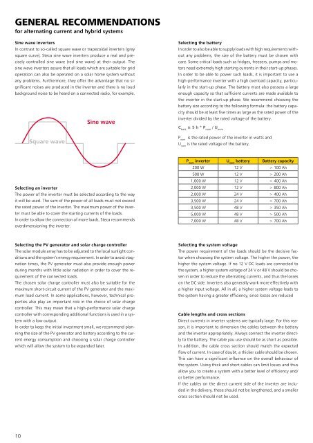
Sine wave inverters<br />
In contrast to so-called square wave or trapezoidal inverters (grey<br />
square curve), <strong>Steca</strong> sine wave inverters produce a real and precisely<br />
controlled sine wave (red sine wave) at their output. The<br />
sine wave inverters assure that all loads which are suitable for grid<br />
operation can also be operated on a solar home system without<br />
any problems. Furthermore, they offer the advantage that no significant<br />
noises are produced in the inverter and there is no loud<br />
background noise to be heard on a connected radio, for example.<br />
Sine wave<br />
Selecting the battery<br />
In order to also be able to supply loads with high requirements without<br />
any problems, the size of the battery must be chosen with<br />
care. Some critical loads such as fridges, freezers, pumps and motors<br />
need extremely high starting currents in their start-up phases.<br />
In order to be able to power such loads, it is important to use a<br />
high-performance inverter with a high overload capacity, particularly<br />
in the start-up phase. The battery must also possess a large<br />
enough capacity so that sufficient currents are made available to<br />
the inverter in the start-up phase. We recommend choosing the<br />
battery size according to the following formula: the battery capacity<br />
should be at least five times as large as the rated power of the<br />
inverter divided by the rated voltage of the battery.<br />
C batt<br />
≥ 5 h * P nom<br />
/ U nom<br />
Square wave<br />
P nom<br />
is the rated power of the inverter in watts and<br />
U nom<br />
is the rated voltage of the battery.<br />
Selecting an inverter<br />
The power of the inverter must be selected according to the way<br />
it will be used. The sum of the power of all loads must not exceed<br />
the rated power of the inverter. The maximum power of the inverter<br />
must be able to cover the starting currents of the loads.<br />
In order to allow the connection of more loads, <strong>Steca</strong> recommends<br />
overdimensioning the inverter.<br />
P nom<br />
inverter U nom<br />
battery Battery capacity<br />
200 W 12 V > 100 Ah<br />
500 W 12 V > 200 Ah<br />
1,000 W 12 V > 400 Ah<br />
2,000 W 12 V > 800 Ah<br />
2,000 W 24 V > 400 Ah<br />
3,500 W 24 V > 700 Ah<br />
3,500 W 48 V > 350 Ah<br />
5,000 W 48 V > 500 Ah<br />
7,000 W 48 V > 700 Ah<br />
Selecting the <strong>PV</strong> generator and solar charge controller<br />
The solar module array has to be adjusted to the local sunlight conditions<br />
and the system‘s energy requirement. In order to avoid stagnation<br />
times, the <strong>PV</strong> generator must also provide enough power<br />
during months with little solar radiation in order to cover the requirement<br />
of the connected loads.<br />
The chosen solar charge controller must also be suitable for the<br />
maximum short-circuit current of the <strong>PV</strong> generator and the maximum<br />
load current. In some applications, however, technical properties<br />
also play an important role in the choice of solar charge<br />
controller. This may mean that a high-performance solar charge<br />
controller with corresponding additional functions is used in a system<br />
with a low output.<br />
In order to keep the initial investment small, we recommend planning<br />
the size of the <strong>PV</strong> generator and battery according to the current<br />
energy consumption and choosing a solar charge controller<br />
which will allow the system to be expanded later.<br />
Selecting the system voltage<br />
The power requirement of the loads should be the decisive factor<br />
when choosing the system voltage. The higher the power, the<br />
higher the system voltage. If no 12 V DC loads are connected to<br />
the system, a higher system voltage of 24 V or 48 V should be chosen<br />
in order to reduce the alternating currents, and thus the losses<br />
on the DC side. Inverters also generally work more effectively with<br />
a higher input voltage. All in all, a higher system voltage leads to<br />
the system having a greater efficiency, since losses are reduced<br />
Cable lengths and cross sections<br />
Direct currents in inverter systems are typically large. For this reason,<br />
it is important to dimension the cables between the battery<br />
and the inverter appropriately. Always connect the inverter directly<br />
to the battery. The cable you use should be as short as possible.<br />
In addition, the cable cross section should match the expected<br />
flow of current. In case of doubt, a thicker cable should be chosen.<br />
This can have a significant influence on the overall behaviour of<br />
the system. Using thick and short cables can limit losses and thus<br />
allow you to create a system with a better level of efficiency and/<br />
or better performance.<br />
If the cables on the direct current side of the inverter are included<br />
in the delivery, these should not be lengthened, and a smaller<br />
cross section should not be used.<br />
10