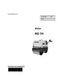
- Page 1 and 2: Service Manual Dumper Machine model
- Page 3: Product evolution: The 1001 dumper
- Page 6 and 7: Table of contents Changing engine o
- Page 8 and 9: Table of contents Hydraulic system
- Page 11 and 12: 1 Operation Operation 1.1 Important
- Page 13 and 14: 1.3 Designated use and exemption fr
- Page 15 and 16: Fig. 4: Hydraulic pump type label F
- Page 17 and 18: 1.6 Operating equipment: overview 1
- Page 19: 1.9 Centre pivot prop B Fig. 9: Cen
- Page 24 and 25: Specifications Fuel injection pump
- Page 26 and 27: Specifications 2.8 Drive specificat
- Page 28 and 29: Specifications 2.11 Electric system
- Page 30 and 31: Specifications 2.15 General tighten
- Page 32 and 33: Specifications Tightening torques f
- Page 34 and 35: Specifications 2.16 Dimensions mode
- Page 37 and 38: 3 Maintenance 3.1 Fluids and lubric
- Page 39 and 40: Maintenance Maintenance plan/servic
- Page 41 and 42: Maintenance plan/service hours (s/h
- Page 43 and 44: 3.5 Fuel system Specific safety ins
- Page 45 and 46: Bleeding the fuel system Danger! Ma
- Page 47 and 48: Replacing the fuel filter Fig. 4: F
- Page 49 and 50: Filling up engine oil Fig. 6: Oil d
- Page 51 and 52: Replacing the engine oil filter car
- Page 53 and 54: Checking/filling up coolant FULL LO
- Page 55 and 56: 3.8 Air filter Weekly check of air
- Page 57 and 58: 3.9 V-belt Checking V-belt tension
- Page 59 and 60: 3.10 Hydraulic system Specific safe
- Page 61 and 62: Changing hydraulic oil Monitoring t
- Page 63 and 64: 3.11 Lubrication points Maintenance
- Page 65 and 66: 3.13 Changing wheels Danger! Use of
- Page 67 and 68: Maintenance Instructions concerning
- Page 69 and 70: 3.15 Battery master switch A C Fig.
- Page 71:
Engine
- Page 74 and 75:
Engine Water pump Exhaust manifold
- Page 76 and 77:
Engine 4.3 Engine overview 3TNV76-X
- Page 78 and 79:
Engine 4.4 Fuel system (from AB1000
- Page 80 and 81:
Engine 4.6 Tightening order for cyl
- Page 82 and 83:
Engine 4.9 Fuel injection time (up
- Page 84 and 85:
Engine 4.11 Adjusting engine revs A
- Page 86 and 87:
Engine 4.15 Oil pressure switch Mea
- Page 88 and 89:
Engine Insufficient engine output E
- Page 91 and 92:
5 Travelling drive Travelling drive
- Page 93 and 94:
Variable displacement pump: diagram
- Page 95 and 96:
7 6 1 2 Pos. Description 1 Forwards
- Page 97 and 98:
Variable displacement pump: design
- Page 99 and 100:
Connecting plate with valves 2 1 6
- Page 101 and 102:
5.4 Front hydraulic motor 4 Pos. De
- Page 103 and 104:
Pos. Description 1 Sealing kit 2 Se
- Page 105 and 106:
5.6 Towing and transporting the mac
- Page 107 and 108:
5.7 Test instruction Pilot pressure
- Page 109:
Brakes
- Page 112 and 113:
Brakes Brake diagram � Hydraulic
- Page 114 and 115:
Brakes Brake diagram � � Hydrau
- Page 117 and 118:
7 Steering system 7.1 Steering circ
- Page 119 and 120:
7.3 Steering unit connections Port
- Page 121 and 122:
Steering unit 1 2 3 4 11 12 5 6 10
- Page 123:
Hydraulic system
- Page 126 and 127:
Hydraulic system 8.2 Test instructi
- Page 128 and 129:
Hydraulic system 8.4 Diagram up to
- Page 130 and 131:
Hydraulic system 8.6 Diagram from s
- Page 132 and 133:
Hydraulic system 8.8 Hydraulics dia
- Page 135 and 136:
9 Electric system Electric system 9
- Page 137 and 138:
9.4 Electric components 9.5 Fuse bo
- Page 139 and 140:
9.7 Fuse box in instrument panel (f
- Page 141 and 142:
Electric system Electric system SER
- Page 143 and 144:
9.10 Wiring diagram version 1 A4 up
- Page 145 and 146:
9.12 Wiring diagram version 1 A4 fr
- Page 147 and 148:
9.14 Main wiring harness from AB100
- Page 149 and 150:
9.16 Engine wiring harness from AB1
- Page 151 and 152:
Electric system Wiring diagram: ove
- Page 153 and 154:
9.18 Wiring diagram A3 up to serial
- Page 155 and 156:
9.20 Wiring diagram A3 from serial
- Page 157 and 158:
9.22 Main wiring harness from AB100
- Page 159 and 160:
9.24 Engine wiring harness from AB1
- Page 162:
Neuson Limited Crown Business Park