Service Manual - Wacker Neuson
Service Manual - Wacker Neuson
Service Manual - Wacker Neuson
You also want an ePaper? Increase the reach of your titles
YUMPU automatically turns print PDFs into web optimized ePapers that Google loves.
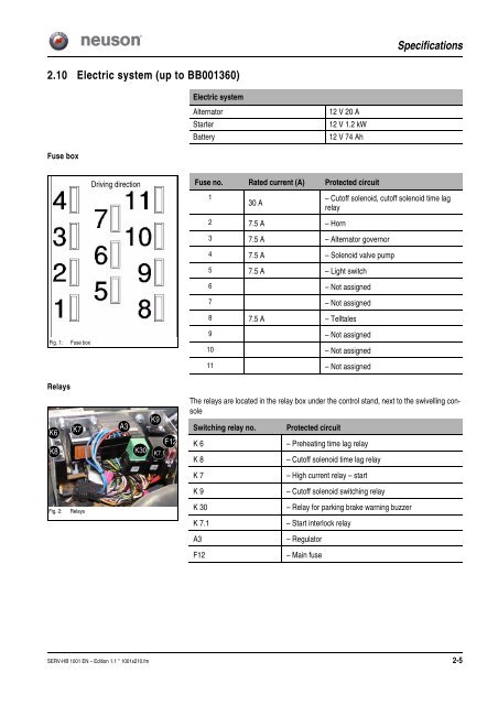
2.10 Electric system (up to BB001360)<br />
Fuse box<br />
Fig. 1: Fuse box<br />
Relays<br />
K6<br />
K8<br />
K7<br />
Fig. 2: Relays<br />
Electric system<br />
Alternator 12 V 20 A<br />
Starter 12 V 1.2 kW<br />
Battery 12 V 74 Ah<br />
Specifications<br />
Driving direction Fuse no. Rated current (A) Protected circuit<br />
1<br />
30 A<br />
– Cutoff solenoid, cutoff solenoid time lag<br />
relay<br />
2 7.5 A – Horn<br />
3 7.5 A – Alternator governor<br />
4 7.5 A – Solenoid valve pump<br />
5 7.5 A – Light switch<br />
6 – Not assigned<br />
7 – Not assigned<br />
8 7.5 A – Telltales<br />
9 – Not assigned<br />
10 – Not assigned<br />
11 – Not assigned<br />
The relays are located in the relay box under the control stand, next to the swivelling console<br />
K9<br />
A3 Switching relay no. Protected circuit<br />
K30<br />
F12<br />
K7.1<br />
K 6 – Preheating time lag relay<br />
K 8 – Cutoff solenoid time lag relay<br />
K 7 – High current relay – start<br />
K 9 – Cutoff solenoid switching relay<br />
K 30 – Relay for parking brake warning buzzer<br />
K 7.1 – Start interlock relay<br />
A3 – Regulator<br />
F12 – Main fuse<br />
SERV-HB 1001 EN – Edition 1.1 * 1001s210.fm 2-5


