COMPARISON OF SOLAR CONCENTRATORS
COMPARISON OF SOLAR CONCENTRATORS
COMPARISON OF SOLAR CONCENTRATORS

You also want an ePaper? Increase the reach of your titles
YUMPU automatically turns print PDFs into web optimized ePapers that Google loves.
Solar Energy. Vol. 18, pp. 93-II1 Pergamon Press 1976. Printed in Great Britain<br />
<strong>COMPARISON</strong> <strong>OF</strong> <strong>SOLAR</strong> <strong>CONCENTRATORS</strong><br />
ARI RABL<br />
Solar Energy Group, Argonne National Laboratory, Argonne, IL 60439, U.S.A.<br />
(Received 23 April 1975: in revised form 10 December 1975)<br />
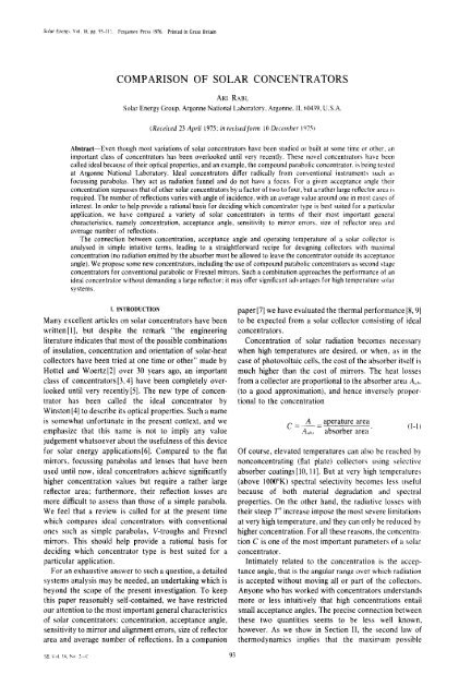
Abstract--Even though most variations of solar concentrators have been studied or built at some time or other, an<br />
important class of concentrators has been overlooked until very recently. These novel concentrators have been<br />
called ideal because of their optical properties, and an example, the compound parabolic concentrator, is being tested<br />
at Argonne National Laboratory. Ideal concentrators differ radically from conventional instruments such as<br />
focussing parabolas. They act as radiation funnel and do not have a focus. For a given acceptance angle their<br />
concentration surpasses that of other solar concentrators by a factor of two to four, but a rather large reflector area is<br />
required. The number of reflections varies with angle of incidence, with an average value around one in most cases of<br />
interest. In order to help provide a rational basis for deciding which concentrator type is best suited for a particular<br />
application, we have compared a variety of solar concentrators in terms of their most important general<br />
characteristics, namely concentration, acceptance angle, sensitivity to mirror errors, size of reflector area and<br />
average number of reflections.<br />
The connection between concentration, acceptance angle and operating temperature of a solar collector is<br />
analysed in simple intuitive terms, leading to a straightforward recipe for designing collectors with maximal<br />
concentration (no radiation emitted by the absorber must be allowed to leave the concentrator outside its acceptance<br />
angle). We propose some new concentrators, including the use of compound parabolic concentrators as second stage<br />
concentrators for conventional parabolic or Fresnel mirrors. Such a combination approaches the performance of an<br />
ideal concentrator without demanding a large reflector: it may offer significant advantages for high temperature solar<br />
systems.<br />
I. INTRODUCTION<br />
Many excellent articles on solar concentrators have been<br />
written[l], but despite the remark "the engineering<br />
literature indicates that most of the possible combinations<br />
of insulation, concentration and orientation of solar-heat<br />
collectors have been tried at one time or other" made by<br />
Hottel and Woertz[2] over 30 years ago, an important<br />
class of concentrators [3, 4] have been completely over-<br />
looked until very recently [5]. The new type of concen-<br />
trator has been called the ideal concentrator by<br />
Winston[4] to describe its optical properties. Such a name<br />
is somewhat unfortunate in the present context, and we<br />
emphasize that this name is not to imply any value<br />
judgement whatsoever about the usefulness of this device<br />
for solar energy applications[6]. Compared to the flat<br />
mirrors, focussing parabolas and lenses that have been<br />
used until now, ideal concentrators achieve significantly<br />
higher concentration values but require a rather large<br />
reflector area; furthermore, their reflection losses are<br />
more difficult to assess than those of a simple parabola.<br />
We feel that a review is called for at the present time<br />
which compares ideal concentrators with conventional<br />
ones such as simple parabolas, V-troughs and Fresnel<br />
mirrors. This should help provide a rational basis for<br />
deciding which concentrator type is best suited for a<br />
particular application.<br />
For an exhaustive answer to such a question, a detailed<br />
systems analysis may be needed, an undertaking which is<br />
beyond the scope of the present investigation. To keep<br />
this paper reasonably self-contained, we have restricted<br />
our attention to the most important general characteristics<br />
of solar concentrators: concentration, acceptance angle,<br />
sensitivity to mirror and alignment errors, size of reflector<br />
area and average number of reflections. In a companion<br />
SE V,~I 18. No 2--( 93<br />
paper [7] we have evaluated the thermal performance [8, 9]<br />
to be expected from a solar collector consisting of ideal<br />
concentrators.<br />
Concentration of solar radiation becomes necessary<br />
when high temperatures are desired, or when, as in the<br />
case of photovoltaic cells, the cost of the absorber itself is<br />
much higher than the cost of mirrors. The heat losses<br />
from a collector are proportional to the absorber area Ao~,<br />
(to a good approximation), and hence inversely propor-<br />
tional to the concentration<br />
C- A _aperature area (1-11<br />
A,,h~ absorber area"<br />
Of course, elevated temperatures can also be reached by<br />
nonconcentrating (flat plate) collectors using selective<br />
absorber coatings[lO, 11]. But at very high temperatures<br />
(above IO00°K) spectral selectivity becomes less useful<br />
because of both material degradation and spectral<br />
properties. On the other hand, the radiative losses with<br />
their steep T 4 increase impose the most severe limitations<br />
at very high temperature, and they can only be reduced by<br />
higher concentration. For all these reasons, the concentra-<br />
tion C is one of the most important parameters of a solar<br />
concentrator.<br />
Intimately related to the concentration is the accep-<br />
tance angle, that is the angular range over which radiation<br />
is accepted without moving all or part of the collectors.<br />
Anyone who has worked with concentrators understands<br />
more or less intuitively that high concentrations entail<br />
small acceptance angles. The precise connection between<br />
these two quantities seems to be less well known,<br />
however. As we show in Section I1, the second law of<br />
thermodynamics implies that the maximum possible
94 ARI RABL<br />
concentration for a given acceptance half angle O, is<br />
1/sin O, for two-dimensional (trough-like) concentrators,<br />
and l/sin 2 0,. for three-dimensional ones.t Stated in terms<br />
of the f number (=ratio of focal length/aperture<br />
diameter) this means that no optical system can have an f<br />
number less than 1/2. This limit plays the same role for<br />
radiation concentrators as the Carnot efficiency (T~- I",)/<br />
T~ does for heat engines; we suggest therefore the use of<br />
the maximum or ideal concentration<br />
and<br />
1<br />
C ideal 2 din, = sin O, (I-2)<br />
I<br />
C ideal 3 dim -- sin 2 0, (I-3)<br />
as standard to which any real concentrators can be<br />
compared. While most conventional concentrators fall<br />
short of this value by a factor of at least two, the above<br />
mentioned ideal concentrators actually reach this limit.<br />
Errors in mirror surface or alignment can be character-<br />
ised by an angle A, defined as one-sided average deviation<br />
from the perfect value. A ray undergoing n reflections<br />
may deviate from the correct direction by as much as<br />
2nA. If no radiation is to miss the target, the nominal<br />
acceptance half angle O, of the collector must be<br />
increased by this amount, with a corresponding loss of<br />
concentration. Obviously, the effect of mirror errors<br />
depends on the relative magnitude of A and the angular<br />
width of the source. In practice, the effect of the mirror<br />
errors may be somewhat smaller since the errors are likely<br />
to be random, resulting in partial cancellations. Detailed<br />
analyses of mirror errors, assuming for example a<br />
Gaussian distribution, can be found elsewhere [1], but for<br />
a first order estimate of the sensitivity to mirror errors it<br />
suffices to specify the acceptance angle and the average<br />
number of reflections (n).<br />
The average number of reflections (n) is also needed to<br />
assess reflection losses. The fraction of the radiation<br />
incident on the aperture which is transmitted to the<br />
absorber can be approximated[12] by<br />
z = p
/ / \<br />
/ "~ \<br />
// \\<br />
I<br />
S /<br />
!<br />
/<br />
!<br />
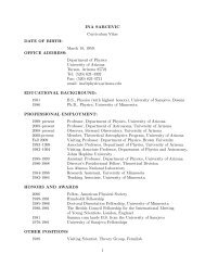
Fig. 1. Radiation transfer from source S through aperture A of<br />
concentrator to absorber A.~..<br />
above; in other words, it is uniformly distributed over all<br />
angles 10l_< 10~1. For further simplification, we assume the<br />
system to be in infinite empty space, or equivalently,<br />
enclosed by black walls at absolute zero temperature. If<br />
both source and absorber are black bodies at tempera-<br />
tures Ts and Tobs, respectively, the heat transfer between<br />
the two is easy to calculate. The source emits an amount<br />
of radiation<br />
of which a fraction<br />
Qs = 4 ~rr2tr T 4 (II-2)<br />
Fs~A =<br />
hits the aperture (N.B.: the aperture is flat in the limit<br />
A/R2 0). With perfect concentrator optics, no radiation<br />
is lost between aperture and absorber, and thus the heat<br />
radiated from the source to the absorber is<br />
A<br />
2<br />
r<br />
Qs~b~ = QsFs~A = A-R--~ o'T~. (II-3)<br />
The absorber, in turn, radiates an amount<br />
Q.b, = A.o,eT~b~, (II-4)<br />
and the fraction E ob,os of this radiation which reaches the<br />
source cannot exceed unity (Eab~S is essentially an<br />
exchange factor as defined by Sparrow and Cess[13]).<br />
Hence the radiative transfer from absorber to source is<br />
with<br />
T 4<br />
Q abs~S ~ E abs~sAabsO- abs (II-5)<br />
E ~b~s ~ 1. (II-6)<br />
By the second law of thermodynamics, there cannot be<br />
any net heat transfer between two bodies of equal<br />
temperatures; for the present situation this implies<br />
Qso.b~- Q.b~s = 0 if T.b, = Ts. (II-7)<br />
Combining eqns (II-3), (II-5) and (1I-7), we obtain the<br />
relation<br />
1.2<br />
A ~ = E ob.~sA~b~, (II-8)<br />
Comparison of solar concentrators<br />
from which we can read off the concentration as<br />
A R: _ E"~-s<br />
c = A.b, = ~ r E.,,~s = sin ~ 0," (1I-9)<br />
In view of the obvious constraint E,,~,~s < - l, eqn (I1-6).<br />
we conclude that the concentration must satisfy<br />
95<br />
1<br />
C -< sin 2 0,' (II-10)<br />
Even though we have derived this result for a particular<br />
geometry, it is completely general. For, suppose a<br />
different arrangement were used to produce the specified<br />
radiation, and an optical system were found with a<br />
concentration greater than allowed by eqn (I1-10). Since<br />
aperture and angular width are the only relevant<br />
parameters, such a concentrator could also be used in the<br />
geometry of Fig. 1 and hence the second law of<br />
thermodynamics would be violated.<br />
So far we have assumed the absorber to be surrounded<br />
by vacuum. Now, suppose the absorber is covered by a<br />
parallel slab of a transparent medium with index of<br />
refraction n. If the radiation incident on the slab is<br />
completely diffuse, then inside the slab it will be restricted<br />
to angles 101---10.1, where sin0. =l/n by Snell's law.<br />
Thus, further concentration by a factor 1/(sin~' 0,, t = n: is<br />
allowed by eqn (II-10), and the total concentration is<br />
bounded only by<br />
M 2<br />
C < - . . (II-11}<br />
sin- 0,"<br />
There is no conflict, however, between this value and the<br />
second law because an emitter in a medium of index n<br />
radiates n 2 as much energy as an emitter in vacuum, a fact<br />
evidenced by the formula for the Stephan-Boltzmann<br />
constant [ 14]<br />
2~. -s n2k 4<br />
~r= 15 co'~h ~" (II-12)<br />
with k = Boltzmann constant, h = Planck's constant, and<br />
Co=Velocity of light in vacuum. As an immediate<br />
corollary we learn that the increase in concentration<br />
brought about by a medium of index n >1 does not<br />
reduce radiative losses (unless the medium has low<br />
thermal conductivity and is opaque to infrared). In<br />
general, the use of a medium with n > 1 for the purpose of<br />
increasing concentration is advisable only when high cost<br />
demands that the absorber area be as small as possible.<br />
This is relevant for photo cells, and in Section IV we shall<br />
discuss a design suitable for that application.<br />
It seems appropriate to define ideal concentration as<br />
the maximum concentration permitted by the second law<br />
of thermodynamics, and to use this as a standard of<br />
comparison for real concentrators. This is strictly<br />
analogous to the use of the Carnot efficiency<br />
Yl - T2<br />
rl,- T~<br />
/I1-13)
96 ARI RABL<br />
in discussing heat engines. The concentration provided by<br />
any three-dimensional optical system must satisfy<br />
n 2<br />
C3,,~
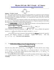
Q CO<br />
Fig. 2. Solar geometry, x-axis points towards solar noon; y-axis<br />
points east; z-axis=axis of rotation; a =solar inclination;<br />
A = latitude; /3 = collector tilt from equatorial plane; fi, = unit<br />
vector normal to collector (assume collector runs east-west);<br />
ri,.- unit vector normal to earth's surface; h, = unit vector in<br />
direction of sun.<br />
with<br />
E = 23°27 '.<br />
\<br />
--- 2rr/(365.25 days)<br />
D = time after winter solstice, in days<br />
(assuming circular orbit).<br />
Let h, be the unit vector from earth to sun and h,. the unit<br />
vector normal to the collector aperture, the collector tilt/3<br />
being measured with respect to the equatorial plane. The<br />
collector is assumed to be east-west symmetric. One<br />
would like to know the angle of incidence 0 of solar<br />
radiation on the collector, as well as the change in solar<br />
elevation zX0,, ("vertical solar swing") during the day and<br />
during the year. Of course these angles are independent of<br />
the earth's radius (since the sun can be considered to be<br />
infinitely far away, for this discussion), and thus it is easy<br />
to see that they must also be independent of the latitude at<br />
which the collector is located. The (x, y, z) coordinate<br />
system of Fig. 2 is fixed in the earth, with the z-axis as axis<br />
of rotation and the x-axis pointing towards the sun at<br />
noon. In these coordinates the unit vectors ri,. and h~ take<br />
the form<br />
and<br />
with<br />
and<br />
h, = (cos/3, 0, sin/3)<br />
rL = (cos a cos cot, -cos a sin wt, sin a)<br />
co = 27r/(24 hr)<br />
t = time after noon, in hr.<br />
This yields the angle of incidence 0 as<br />
Comparison of solar concentrators<br />
(III-2)<br />
(III-3)<br />
cos 0 = L • h,. = cos/3 cos a cos wt + sin/3 sin a.<br />
(III-4)<br />
In order to find the solar elevation, we consider the<br />
projection<br />
n,~, = (cos a cos cot, 0, sin a) (III-5)<br />
of ~, on the y = 0 plane, i.e. the plane spanned by the sun<br />
at noon and by the axis of rotation. The solar elevation 0,<br />
from the equatorial plane is found by dotting the unit<br />
vector<br />
~,, = {cos c~ cos cot, O, sin a I( 1 - cos: c~ sin-' cot ) ~:<br />
(111-6)<br />
into the unit vector (1,0,0t along the x-axis. The result<br />
cos 0, = cos ~ cos tot(1 - cos c~ sin~ cot }<br />
can be written in the form[15]<br />
tan<br />
tan 0, = - - (III-7)<br />
COS col '<br />
The extreme values of 0, occur at solstice, and they are<br />
plotted vs time of day in Fig. 3.<br />
90<br />
70<br />
,* 60<br />
a~" 5O<br />
'¢O O<br />
30<br />
¢O<br />
Solar elevation<br />
/3 on solstice<br />
I I I L _ _<br />
I 2 3 4 5<br />
t [hours after noon]<br />
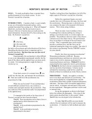
Fig. 3. Solar elevation 0, (relative to equatorial planel 0 days. 30<br />
days, 60 days and 80 days from solstice, as labeled by the number<br />
next to the curves. To illustrate the use of this graph the dotted<br />
line has been added corresponding to the acceptance half angle of<br />
a stationary collector laligned east-west) which can coiled direct<br />
sunlight for at least 7 hr a day.<br />
In order to find the vertical solar swing ~0, during the<br />
central t hours of the day, one calculates 0, from eqn<br />
(Ili-7) and subtracts the noon elevation c~. The largest<br />
daily swing occurs at solstice, both summer and winter,<br />
and hence we can obtain from Fig. 3 the acceptance angle<br />
which a collector must have in order to catch the sun for a<br />
specified minimum number of hours per day without any<br />
diurnal tracking. The acceptance should, of course, be<br />
even larger to accommodate the finite size of the sun<br />
(angular radius & = 4.7 mrad) as well as mirror inac-<br />
curacies. The latter can be characterized by an angle ,5 ....<br />
the amount by which the acceptance half angle will be<br />
smeared out; neglecting position errors. &,, is twice the<br />
maximum slope error if one insists that no radiation miss<br />
the absorber and if n = I.<br />
Hence, the maximum concentration for a two-<br />
dimensional solar concentrator (aligned along the East-<br />
West direction) is<br />
1<br />
C: ,,,,,. ,~;,,,,; - (111-8)<br />
sin (1/2~0, + & + &,: )'<br />
and this is actually achieved by the ideal concentrators<br />
described in the next section. Figure 4 shows the highest<br />
possible concentration vs collection time at solstice for a<br />
97
98 ARI RABL<br />
{ 2 -- ~C/deal foreost-west coffector<br />
\ without diurnal trackinq<br />
I<br />
I0<br />
o -<br />
~ (but with occasional<br />
\'\ tilt adjustments)<br />
\\<br />
\ c,...ol<br />
\ east-west x polar \ \<br />
.g 7<br />
6<br />
4_ C/deal cart- wegt ~ "K<br />
3 t r u ~<br />
2<br />
I<br />
o 1 I I I I I I I I 1 l<br />
2 3 4 5 ~ ? 8 9 tO II r2<br />
Collection time - 2 tc<br />
Fig. 4. Maximum possible concentration for non-tracking solar<br />
collectors, as function of minimum collection time 2t,. The finite<br />
size of the sun is included, with 8~ = l/4t The solid lines<br />
correspond to perfect mirrors, and the dashed lines to realistic<br />
mirrors with 8., + 8~ = 1 °. The values of G~,,, for a combined<br />
east-west = polar concentrator can probably not be reached in<br />
practice.<br />
collector without diurnal tracking and for a truly<br />
stationary collector. Both perfect mirrors, & = 0, and<br />
realistic mirrors, & + (% = 1 e, are considered; values for<br />
larger errors can be extrapolated from these curves.<br />
Some additional concentration may be gained because<br />
the azimuthal swing of the sun is less than 180 ° during the<br />
useful collection time. If the cutoff time is t~ hours after<br />
noon, then a second concentrator, oriented along the polar<br />
axis, could in principle boost the concentration by an<br />
additional factor<br />
\<br />
I<br />
C .o,..- sin (wb + 8s + 8m )" (III-9)<br />
Unfortunately, this may not be possible to achieve in<br />
practice. For example, a set of two crossed compound<br />
parabolic concentrators (one east-west, one polar) will<br />
reject certain rays, even though they arrive within the<br />
solid angle defined by 0 ........ and 0~o~. This is due to<br />
differences between two-dimensional and three-<br />
dimensional reflectors, as discussed in Section V.<br />
We see from Fig. 3 that a collector with an acceptance<br />
half-angle below approximately 40 ° needs occasional tilt<br />
adjustments. To find out when adjustments are necessary,<br />
we calculate the solar elevation 0o~ relative to the<br />
collector. More precisely, 0~c is measured from the plane<br />
spanned by the collector normal and the east-west<br />
direction, and hence it is given by 0o of eqn (III-7), apart<br />
from a shift by the collector tilt/3,<br />
Ooc = O~ - ft. (III-lO)<br />
This fact allows us to rewrite eqn (III-7) as<br />
tan<br />
tan (0o~ +/3) = - - (III-11)<br />
cos tot<br />
(Of course, this relation can also be obtained from<br />
cos 0oc = i • i0).<br />
In Table 1 we list the number of tilt changes necessary<br />
for a collector with acceptance half-angle 0c, based on a<br />
point like sun. For a real collector the concentration can<br />
be obtained from 0~ by the formula<br />
Co<br />
C (III-12)<br />
sin(0c + & + 8m)<br />
where Co-< 1 is a number [1/(2f-number)] which depends<br />
on the concentrator type and states by how much the<br />
concentration falls short of the ideal limit. The entries in<br />
Table 1 are computed according to the following<br />
procedure: on summer solstice the collector normal is<br />
pointed at an angle 0c above the solar noon elevation of<br />
23o27 ' . It is left in this position until the day when the<br />
collection time falls below the specified minimum, at<br />
which time the collector normal is again adjusted to an<br />
angle 0~ above solar noon elevation, etc. For a truly<br />
Table 1. Adjustments of collector tilt. Require minimum collection time 7 hr/day (except for 0c = 5.50 min. collect.<br />
time = 6.78 hr/day)<br />
Accept Half Angle 0<br />
• c<br />
ideal concentration<br />
for perfect mirrors<br />
19, 5 °<br />
(3.0)<br />
14 °<br />
I4. 13)<br />
! ]1 °<br />
(5. 24)<br />
9 °<br />
(6. 39)<br />
8 °<br />
(7. 19)<br />
7 °<br />
(8.21)<br />
6,5 °<br />
(8.83)<br />
6 °<br />
(% 57)<br />
8,5 °<br />
(i0.43)<br />
Collection Time<br />
Aver, Over year<br />
(hours/day)<br />
9. 22<br />
8,76<br />
8.60<br />
8.38<br />
8.22<br />
Number of<br />
Adjust./Ycar<br />
Shortest Period<br />
w/o Adjustment<br />
180 days<br />
35 days<br />
35 days<br />
Z4 days<br />
16 days<br />
Average Collection Time<br />
if Tilt Adjusted Every Day<br />
(hours/day)<br />
I0. 72<br />
I0.04<br />
9.52<br />
9.08<br />
8.82<br />
8, 04 20 13 days 8. 54<br />
7.96 26 9 days 8. 38<br />
7. 78 80 i day 8. 18<br />
7.60 84 1 day<br />
8.00<br />
I
stationary collector, the limit of useful concentration is<br />
about two; for photovoltaic applications, this can be<br />
increased to about four by means of a dielectric medium<br />
with n = 1.5.<br />
IV. IDEAL <strong>CONCENTRATORS</strong> IN TWO DIMENSIONS<br />
Following Winston[4], we call those concentrators<br />
which actually reach the ideal limit (l/sin0, in two,<br />
l/sin -~ 0, in three dimensions) ideal concentrators. (Of<br />
course, this name refers only to their optical properties,<br />
without any regards for practical matters such as<br />
economics). In this section, we consider only two-<br />
dimensional concentrators, also called cylindrical or<br />
trough-like.<br />
In 1965 Winston and Hinterberger[3] discovered an<br />
example of this class, called compound parabolic concen-<br />
trator (CPC) and shown in Fig. 5. It consists of parabolic<br />
reflectors which funnel the radiation from aperture to<br />
absorber. The right and the left half belong to different<br />
parabolas, as expressed by the name CPC. The axis of the<br />
right branch, for instance, makes an angle 0, with the<br />
collector midplane, and its focus is at A. At the end points<br />
C and D, the slope is parallel to the collector midplane.<br />
\ \ AXIS <strong>OF</strong> /<br />
, -\ cpc /<br />
",, \\\ //]<br />
AXIS <strong>OF</strong> ', ~ \ , / /<br />
PARABOLA"~, \ \\ ~f~// b pARABOLA<br />
',\ \',/ /<br />
"\ 'i/ /<br />
\/\\/<br />
FOCUS <strong>OF</strong> ,~.-4 -V I<br />
PARABOLA ..~C- --<br />
Fig. 5. Compound parabolic concentrator.<br />
It is easy to show that this instrument has a<br />
concentration of<br />
1<br />
C ideal 2 dim -- sin 0,<br />
Recalling eqn (II-9), we see that a concentrator is ideal if<br />
and only if the exchange factor E,,, .......... ,, for radiation<br />
going from absorber to the source is<br />
E,,~, .......... ,~li~,,,,I = I. (IV-l)<br />
In other words, all radiation emitted by the absorber must<br />
get to the source, which was specified to cover an angular<br />
region 10l < 0,. This is equivalent to the requirement that<br />
all rays incident on the aperture inside the acceptance<br />
angle and none of the rays outside the acceptance angle<br />
pass to the absorber (this property is plotted in Fig. 6). By<br />
tracing rays emanating from the absorber, in particular<br />
from its end points A and B, one learns that indeed no<br />
radiation from the absorber can leave the CPC outside its<br />
acceptance angle.<br />
The CPC is not an imaging instrument, by contrast to a<br />
Comparison of solar concentrators<br />
tu 1.O<br />
Q_<br />
Lo<br />
t~ 0.5<br />
.J<br />
~9<br />
"~ o<br />
FULL CPC<br />
TRUNCATED CPC<br />
CPC WITH MIRROR ERROR A<br />
L<br />
if.. 9 '.<br />
0c Oin<br />
Fig. 6. Fraction of the radiation incident on aperture at angle 0,,<br />
which reaches absorber, for ideal concentrator in two dimensions.<br />
with acceptance half angle 0,, assuming reflectivity t~ = 1.<br />
• untruncated ideal concentrator with perfect reflectors:<br />
...... . truncated ideal concentrator with perfect reflectors:<br />
......... . untruncated ideal concentrator with surface errors A.<br />
simple parabola. The flux distribution at the absorber can<br />
easily be found for certain special cases: rays incident at<br />
0 =+0,(-0,) will be brought to focus at B(A), while<br />
radiation which is uniformly spread over all angles i01 < 0,<br />
will be totally diffuse when it gets to the absorber. For<br />
other cases, the radiation pattern at the absorber is more<br />
complicated and has to be determined by detailed ray<br />
tracing.<br />
Conventional imaging instruments such as Fresnel<br />
lenses or mirrors tend to fall short of the ideal<br />
concentration by a factor of two to four. However, a price<br />
must be paid for the high performance of ideal<br />
concentrators: their mirror area is rather large. Fortu-<br />
nately, this disadvantage can be alleviated by truncation.<br />
The top portion of the reflectors in Fig. 5 does not<br />
intercept much radiation, and it can be cut off without<br />
much loss in concentration. We have studied this question<br />
in another paper, and present only some results in Figs. 7<br />
and 8. Figure 7 is a graph of reflector/aperture ratio AR/A<br />
vs concentration for various acceptance angles, both for<br />
full and for truncated CPC's. For example, a full CPC<br />
with an acceptance half-angle of 6 ° concentrates by a<br />
factor of 9.6 and requires a total of 10.6m ~ of reflector<br />
area for each m 2 of aperture. When the A~/A ratio is<br />
reduced to 5, the concentration is still equal to 8.2.<br />
The number of reflections varies both with angle of<br />
incidence 0,, and with point of incidence on the aperture.<br />
For solar applications one needs (n (0,,)), the average over<br />
all incidence points at angle 0,,, as well as (n). the average<br />
of (n(O~,,)) over all 0~,, within the acceptance angle. Figure<br />
8 shows (n) along with the high and low values of (n (0~,))<br />
for several acceptance angles (reflector profilesl as a<br />
function of concentration (truncation). The variation of<br />
(n(0~,)) with 0,,, decreases with truncation. This feature is<br />
important because small variation is desirable for the sake<br />
of uniform collector output.<br />
If a CPC is truncated, some rays outside the acceptance<br />
angle (10~,1> 0, ) can reach the absorber, while of course<br />
no rays with 10,,1> 0, are rejected. The resulting increase<br />
in angular acceptance is, however, insignificant in most<br />
99
100<br />
17<br />
16<br />
r~<br />
14<br />
15<br />
~ 12<br />
2<br />
~-- ?<br />
.4<br />
5 8:15 °/'~<br />
3 /<br />
2<br />
I<br />
Truncation of CPS<br />
8 = Acceptance half angle<br />
8-4%"<br />
Fo"cPC I T"<br />
8-6~." ! /<br />
IF I I I I I I I I I I I I I I<br />
0 I 2 3 4 5 6 7 8 9 io It 12 13 f4 ~5<br />
Concentration<br />
Fig. 7. Reflector/aperture ratio as function of concentration for<br />
full and for truncated CPC's.<br />
v<br />
.o<br />
o,_<br />
"6<br />
E<br />
R<br />
2.0<br />
1,9<br />
18<br />
17<br />
16<br />
15<br />
1.4<br />
1.3<br />
1.2<br />
II<br />
I0<br />
09<br />
0.8<br />
07<br />
0.6<br />
05<br />
0.4<br />
03<br />
0.2<br />
OA<br />
i<br />
~8~ = 19.5"<br />
tO, = 33.7"<br />
High value<br />
I 2 3 4 5 6 7 8 9 IO II 12 (3 14 15<br />
Concentration<br />
Fig. 8. Number of reflections for full and for truncated CPC,<br />
computed by ray tracing. The average over all points of impact<br />
was taken at each angle of incidence 0~, in order to find (n(O~,)).<br />
For each of the acceptance half angle 0c in this graph, the high and<br />
low values of (n(O,.)) are shown in addition to the average (n)<br />
over all IO~,J 0c, the fraction of radiation reaching the<br />
absorber is less than l/if; under these conditions the<br />
collector is useless for thermal, marginal for photovoltaic<br />
applications. The fraction of diffuse radiation which is<br />
ARI RABL<br />
accepted is of course 1/(~, independent of any details of<br />
the concentrator, as shown in Section II.<br />
The suitability of the CPC concept for solar applica-<br />
tions is under investigation at Argonne National<br />
Laboratory[6]. Several different design variations are<br />
being constructed and tested, including single large CPC<br />
units as well as panels containing many small CPC's (to<br />
reduce edge losses).<br />
Before proceeding to different concentrator types, we<br />
mention some reflector configurations which transport<br />
radiation from one place to another, with no change in<br />
concentration. Consider, for instance, the CPC (in Fig. 9a)<br />
which, for solar applications in midlatitudes, will be tilted<br />
at an angle between 10 ° and 80 °. Calculations[7] indicate<br />
that in CPC solar collectors convective and radiative heat<br />
losses are comparable. Radiative losses can be reduced by<br />
selective absorber coatings, but this will not improve the<br />
performance greatly unless convection losses are sup-<br />
pressed at the same time. The latter can be accomplished<br />
either by evacuation (impractical unless absorber is<br />
placed inside evacuated cylindrical glass tube) or by<br />
placing the absorber horizontally, facing downward, as<br />
shown in Fig. 9.<br />
"x "<br />
x Pivot<br />
s' / s' R;<br />
(a) (b)<br />
R~ R;<br />
Fig. 9. Convection suppressing cavities for CPC.<br />
The radiation impinging upon surface S in Fig. 9a is<br />
piped around the corner to the horizontal surface S' by a<br />
cylindrical reflector R'. Obviously, there is no change in<br />
concentration, and no radiation is lost apart from<br />
absorption by imperfect mirror surfaces. The losses due<br />
to absorption are easy to estimate because diffuse<br />
radiation passing from S to S' will undergo on the average<br />
(. >, ~.,,,,~r --- ~ (]v-2)<br />
reflections[12] where @ is the angle between S and S' in<br />
radians. Therefore, the fraction of light transmitted from<br />
S to S' is<br />
p = p~J2 (IV-3)<br />
where p is the reflectivity of the mirror R'.<br />
Figure 9b includes some ramifications of this idea. It<br />
may be desirable to create a stagnant air layer below the<br />
absorber, and this can be accomplished by the parallel<br />
reflector section R ~. An additional straight section R ~ may<br />
be necessary for mechanical reasons. The average<br />
number of reflections for diffuse radiation passing<br />
between parallel plates of length l and separation h is
given by the formula[12]<br />
>,,o,,,,,~,,,,,,,, ~-. 1<br />
(n =<br />
and the fraction of radiation transmitted is again<br />
approximated by p ~°>. Inserting realistic numbers, one<br />
finds that the convection suppressing cavity[16] of Fig.<br />
9(b) will cause approximately 1-1.5 extra reflections,<br />
corresponding to absorption losses of 10-15 per cent if<br />
good reflector materials (p ~ 0.9) are used.<br />
Further work is needed to decide to what extent this<br />
type of cavity is practical. Even if wind is kept out by a<br />
cover glass, uneven heating may create small convection<br />
cells inside the cavity thus impairing its insulating value.<br />
This kind of question has to be settled by experiment.<br />
Since the tilt of the CPC may have to be adjusted<br />
periodically, a venetian blind arrangement suggests itself.<br />
In Fig. 9(b), the CPC reflector R and the cylindrical<br />
section R', can pivot around point P, with sections R'~ and<br />
R" sliding past each other.<br />
In 1974 Winston and Hinterberger[17] discovered that<br />
the absorber of a two-dimensional ideal concentrator need<br />
not be flat and parallel to the aperture. They proved that<br />
radiation incident with 101 < 0,. on an aperture of width l<br />
can be concentrated onto any convex absorber of<br />
circumference / sin 0, (see Fig. 10). Sections AD and AF<br />
of the concentrator are convolutes of sections AC and<br />
AB of the absorber. For the rest of the concentrator, one<br />
demands that at any point P of the reflector the reflector<br />
aperature<br />
G I'", --f/~Shad°w<br />
/-<br />
lines<br />
~'"''L\ I "//<br />
/<br />
//<br />
/<br />
/<br />
Fig. 10. Ideal cylindrical concentrator with arbitrary absorber<br />
shape.<br />
Comparison of solar concentrators I01<br />
normal bisect the angle between the line PT (= tangent to<br />
absorber at T) and the ray incident on P at angle 0, (with<br />
(IV-4) respect to collector axis). With starting point D(F) and<br />
slope at each point specified, the entire concentrator<br />
section DE(FG) is uniquely determined. Mathematically<br />
speaking, there is one boundary condition and a first order<br />
differential equation. If the absorber is straight, the<br />
reflector consists of parabolic sections, possibly com-<br />
bined with circular sections. For example, in Fig. l lta),<br />
the portions DE and FG are parabolic, while AD and AF<br />
are circular. Note that in Fig. 1 l(b), sections DD' and D' E<br />
belong to different parabolas. The reflector shape<br />
corresponding to a circular absorber has been calculated<br />
in Ref. [18].<br />
The concentrators shown in Fig. 11 may be very<br />
attractive for solar energy collection: not only is the<br />
absorber material used more efficiently than in other<br />
designs, but there are no losses through the back. This<br />
may be quite an important advantage because it may be<br />
too costly to reduce the effective U-value of the back of a<br />
collector much below 0.5 x 10 ~ w/cm: °K. Compared to<br />
frontal U-values for CPC type solar collectors[7},<br />
approximately 3 x 10 ~ w/cm~" °K for three-fold and 1.4 x<br />
10~w/cm'-°K for ten-fold concentration, the losses<br />
through the back are indeed significant.<br />
As for the U-values of the collectors in Fig. I 1, they can<br />
be calculated with the formulas derived in [7} and [8}.<br />
Differences from the CPC arise (i) from differences (about<br />
-+30 per cent) in the free convective heat transfer<br />
coefficient, and (ii) from the fact that the shape factor for<br />
radiation from absorber to aperture is smaller than for a<br />
I CPC. The latter point is relevant for mirrors with high<br />
absorptivities for low temperature infrared li.e. second<br />
,,'E surface mirrors) because then the reflectors can act as a<br />
~.....~,,,' radiation shield, provided of course their backs are<br />
/'<br />
/<br />
thermally insulated. As far as heat losses are concerned,<br />
configuration l l(b) appears to be particularly favorable.<br />
,G Ehadow lines _ :E<br />
. 8~ e,~<br />
x<br />
~ : - Parabola<br />
a) 4°b~=2w<br />
\<br />
Orcle<br />
i<br />
'k /<br />
J<br />
/cl/~lv' \<br />
, k / :!<br />
/<br />
• c Oc<br />
F' C 8 [,<br />
Fig. 11. Examples of ideal cylindrical concentrators.<br />
[b)
102 ARI RABL<br />
However, the optical losses have to be considered too,<br />
and these are somewhat higher than for a CPC. The<br />
average number of reflections can be calculated<br />
analytically[12]; for example, for the configuration of Fig.<br />
1 l(a) it is about 50 per cent higher than for a CPC of<br />
comparable concentration.<br />
The concentrators mentioned so far possess uniform<br />
concentration for all angles of incidence i0] < 0~ (apart<br />
from the usual cos O factor for non-normal incidence).<br />
For heating and cooling applications, however, the load<br />
varies with the seasons, and a collector with variable<br />
output might be more appropriate. The concentrators<br />
shown in Fig. 12 do indeed have this property. They<br />
consist of a single parabola CD whose axis is parallel to<br />
one of the extreme rays and whose focus is at the edge B<br />
of the absorber; the parabola concentrates all radiation<br />
incident on the aperture BD with )01 < 0~ onto the surface<br />
BC.<br />
The examples shown here have an acceptance half-<br />
angle 0~ = 36 °, and thus they are truly stationary with a<br />
collection time of at least 7 hr per day. Their concentra-<br />
tion is 1.7 = 1/sin O~ at normal incidence, but varies from<br />
zero (winter for a, summer for b) to 3.4 (summer for a,<br />
winter for b), including the cos 0 factor. This "sea shell"<br />
collector is of course constructed according to the same<br />
principle as the other ideal concentrators; no radiation<br />
emitted by the absorber is allowed to escape from the<br />
)--<br />
SUMMER<br />
~ \ / ~J j ,<br />
SOLSTICE<br />
2/._. EOU,.OX !<br />
i i , ,-.-~ \ j<br />
,\-~-~-/% ,<br />
collector outside its acceptance angle, as is readily<br />
verified. The change in concentration can be varied by<br />
truncation to fit the demand curve for a particular user.<br />
For example, with the truncation point at T in Fig. 12(a)<br />
the concentration ranges from 0.7 to 1.7 (again including<br />
the cosine factor) with a mean value of 1.5 at 0 = 0.<br />
The "sea shell" can be combined with the convection<br />
suppressing cavities described earlier, and we have<br />
included this feature in Fig. 12. With a selective absorber<br />
coating, the collector in Fig. 12(a) may well be suited to<br />
drive absorption air conditioners which need tempera-<br />
tures of 100°C or more, a range in which ordinary<br />
flat-plate collectors are considered to be inadequate.<br />
The ordinary CPC (Fig. 5) and the "sea shell" (Fig. 12)<br />
are special limiting cases of a general class of asymmetric<br />
concentrators sketched in Fig. 13. The axis of the left<br />
(right) parabola subtends an angle 6t(6,) with the<br />
absorber normal; FdF~) is the focus of the left (right)<br />
parabola. The acceptance angle is 20< = ~ + ~, and the<br />
geometric concentration is C = 1/sin 0~. The effective<br />
concentration varies from a minimum at 0,, = 45, to a<br />
maximum at or near 0~, = ~, due to the change in<br />
projected aperture area (normal to 0~,). The ordinary CPC<br />
corresponds to 0< = ~ = ~r and the "sea shell" to<br />
20< :~t, ~,=0.<br />
For photovoltaic applications, the two-stage CPC<br />
design[19] of Fig. 14 takes advantage of the extra<br />
/ i <strong>OF</strong><br />
/ VERTICAL <strong>SOLAR</strong> I ........<br />
W,.TER / SW,Ne °~V,~%X2A<br />
,o.,zo.,.. '\ i/<br />
I I I<br />
8) PARABOLA . . 1 4 " ~ , i CIRCLE<br />
rttlt \ Eou .ox<br />
SUMMER APEX<br />
SO LST I C E <strong>OF</strong><br />
/ '\ ~ PARABOLA<br />
/ VERTICAL <strong>SOLAR</strong> \ ~.<br />
/ SWINe -+36* t,<br />
/ ... ~ \~ ~ ABSORBER<br />
I fAxls _<strong>OF</strong> I" ~I<br />
W,NT R L_t "'RABOLAI "-2,1<br />
Fig. 12. Stationary "sea shell" collector with variable concentration, with maximal output in summer (a) and winter<br />
(b).
Axisof R /<br />
[ Extreme ~ /'/<br />
II i~/ // ///<br />
/ ~ "',, / // AxisofL<br />
I !/ "',, / /<br />
/ L.- /<br />
/I i<br />
Fig. 13. Asymmetric ideal concentrator with acceptance angle<br />
20~ = @, + @, and geometric concentration C = l/sin 0~. The<br />
effective concentration varies with angle of incidence. A =<br />
aperture, A.b~ = absorber, R = right parabola, L = left parabola,<br />
F, = focus of R F, = focus of L.<br />
\ /<br />
\ /<br />
Comparison of solar concentrators<br />
f<br />
/<br />
girsl Air n = I<br />
stage x<br />
Secon6 \ ] Dielectric medium<br />
stage ~ n • I<br />
Absorber<br />
Fig. 14. Two stage CPC suitable for photovoltaic applications. The<br />
first stage concentrates by l/sin 0~, the second by n.<br />
concentration allowed by a dielectric medium with index<br />
of refraction n >1 (two CPC's in tandem require less<br />
material than a single CPC filled entirely with the<br />
medium). If the medium is a liquid such as water or oil, the<br />
solar cells can be cooled while collecting useful low-grade<br />
heat. In fact, the relative proportions of electric and<br />
thermal energy match the demands of a typicat residence.<br />
This approach is particularly attractive if used as terminal<br />
concentrators (see Section VII) for a conventional<br />
Fresnel mirror, because then the higher concentration<br />
necessitates efficient cooling and the extra cost of the<br />
second CPC plus liquid is only a small fraction of the<br />
total.<br />
As for the sensitivity to mirror surface errors, the<br />
analysis is equally simple for all ideal concentrators<br />
considered here because their geometry implies that all<br />
rays incident near the cutoff angle, i.e. with 10~,[~0,,<br />
undergo exactly one reflection on their way to the<br />
absorber. In almost all practical applications, the accep-<br />
tance half angle 0~ will be larger than 5 °, and it is<br />
reasonable to assume that the mirror surface errors A will<br />
be fairly small compared to 0~. Therefore, all of the rays<br />
with [0~, [ < 0~ - A and none of the rays with [0,, I > 0~ +/%<br />
will reach the absorber, while in the transition region<br />
0c- A < 10~,1 < 0c + A some rays are accepted and some<br />
are rejected. The resulting angular acceptance is shown<br />
schematically by the dotted line in Fig. 6. (The equality of<br />
the areas under the straight and dotted lines--weighted by<br />
appropriate cosine factors--follows from eqn 11-21).<br />
V. RAY TRACING IN THREE DIMENSIONS AND<br />
FAILURE <strong>OF</strong> IDEAL <strong>CONCENTRATORS</strong><br />
When tracing rays in three-dimensional concentrators it<br />
is not sufficient to consider only rays which lie in a plane<br />
of symmetry. Nonplanar rays can show quite a different<br />
behavior, and they are an essential complication. As an<br />
illustration, we take the extension of the two-dimensional<br />
CPC to three dimensions. One might expect that the<br />
corresponding figure of revolution, a cone with compound<br />
parabolic profile, would act like an ideal three-<br />
dimensional concentrator with concentration I/sin" 0..<br />
This turns out to be almost, but not quite, correct. Figure<br />
15 shows how much of the radiation incident on the<br />
aperture, at angle 0, is actually transmitted to the absorber<br />
even if the mirrors are perfect; this graph has been<br />
obtained by a Monte Carlo technique[4]. Some rays<br />
within the nominal acceptance half-angle 0, are rejected<br />
while some rays with 101 > 0r do get to the absorber. The<br />
transition region 0, is small compared to 0,. "a typical<br />
example being 0, ~ 1 ° for 0, = 16 °. Therefore. if all<br />
radiation within a specified cone of half-angle 0, is to<br />
reach the absorber of a CPC cone, its profile must be<br />
chosen according to a nominal acceptance half-angle<br />
O'c = 0.-+ 1/20,; this results in an actual concentration<br />
which is 5-10 per cent below the ideal limit.<br />
Before proceeding further, it is appropriate to state the<br />
law of specular reflection in vector notation. Define the<br />
unit vectors<br />
[= direction of incident ray<br />
h = direction of normal of reflector surface<br />
= direction of reflected ray<br />
all three pointing away from the surface. The law of<br />
specular reflection states that<br />
(i) angle of incidence = angle of reflection,<br />
I.O<br />
o<br />
_~ o.s<br />
f. fi = ? • t~ IV-l)<br />
Fig. 15. Fraction of the radiation incident on aperture an angle 0,,,<br />
which reaches absorber of compound parabolic cone (three<br />
dimensional CPC) with nominal acceptance angle 0,. Perfect<br />
reflectors with p = I are assumed.<br />
=l<br />
\i
104 ARI RABL<br />
and<br />
(ii) ~, t~ and f lie in the same plane<br />
(rx f). r~ =0. (v-2)<br />
Given any two of these vectors, the third one is uniquely<br />
determined by eqns (V-I) and (V-2), apart from trivial<br />
minus signs. If f and : are specified, ti must be chosen<br />
orthogonal to f x i and to f- f; hence, it must have the<br />
direction of (f × f) x (f- f), and it turns out to be<br />
ri = (f + :)(2 + 2t. f) ~/~. (V-3)<br />
On the other hand, with t and t~ given, t ~ must have the<br />
form af+bti with a and b fixed by :2_1 and<br />
i • tl = f - fi; the result is<br />
: = - f + 2(f' fi)fi. (V-4)<br />
In order to see under what conditions and to what<br />
extent a three-dimensional problem can be treated as a<br />
two-dimensional one, consider the projections of f, ~ and<br />
onto a plane, say the (x, y) plane. The projected angles<br />
of incidence a~,~ and a~,~ are given by<br />
and<br />
COS Oti,~y : ixy " nxy = i~nx + iyny<br />
=f . fi-i~n~<br />
COS 8~,xy = rxy • n~y = rxnx + ryny<br />
= :. h - rzn~,<br />
and they are equal if, and only if, i~n~ = r,n=. This is<br />
obviously satisfied if tl lies in the projection plane. Thus,<br />
in any trough-like concentrator aligned along the z-axis all<br />
incident rays with the same (x, y) projection (plane of the<br />
paper in Fig. 16) are represented by the same two-<br />
dimensional ray tracing diagram, no matter how large<br />
their elevation from the (x, y) plane.<br />
Therefore, rays with the same (x, y) components but<br />
different z components need not be traced separately.<br />
Suppose a planar ray entering with f = (~,, i,, 0) has been<br />
found to leave in the direction g = (s,, s,, 0). Then a ray<br />
entering with<br />
r'=tiS~," ~,,V1-03", ~ z3, " (v-5)<br />
i'~ arbitrary, has the same (x, y) projection and leaves with<br />
^~ .t 2<br />
s = ( s ~ , s,,~, i'~), (v-6)<br />
no matter how many reflections have occurred. (The<br />
equality of i'z and s'~ follows from eqn V-4).<br />
For nonplanar rays the elevation from the (x, y) plane<br />
changes with each reflection. Let f=(i~,iy, iz) be an<br />
arbitrary incident ray, and write the normal tl of the<br />
reflecting surface as<br />
fi = (cos y, sin y, 0);<br />
(b)<br />
(a) /<br />
a a'zr i<br />
~aiXy<br />
"l ,<br />
Fig. 16. Reflection in troughlike (along z-axis) concentrator.<br />
Projection on (x, y) plane (a), and on (y, z) plane (b). The (x, y)<br />
projection is independent of the elevation from the (x, y) plane.<br />
then the reflected ray has the direction<br />
: = ([ix cos 2y + iy sin 2y], [i~ sin 2y - iy cos 2y], - i~).<br />
(V-7)<br />
Let ai,, and at,, be the projected angles on the (y, z)<br />
plane, as indicated in Fig. 16; they are given by<br />
i= r~ (V -8)<br />
tan a,,zr = v- and tan O/r, gy : --.<br />
ly ry<br />
Inserting the y and z components of r, we obtain<br />
tan a~,.~, (V-9)<br />
tan a,,zy = cos 2 7 - sin 2 7 tan ai:, '<br />
where a,.x, = tan '(i~/iy) is the angle shown in Fig. 16(a).<br />
The term sin 2y tan ai,~y is positive, since f and fi lie on<br />
the same side of the reflector, and hence the denominator<br />
in eqn (V-9) is less than one. In the following, we consider<br />
only the case when the reflected ray points downward, i.e.<br />
ry < 0; this implies that the denominator is positive. We<br />
can conclude, therefore, that<br />
O[r,zy ~" O[ ,zv (V-IO)<br />
except in the trivial case when y = 0, corresponding to a<br />
reflector wall parallel to the (y, z) plane.<br />
With this information, one learns at once that the<br />
crossed double CPC of Fig. 17, consisting of one CPC<br />
along the z-axis with acceptance half-angle 0, followed by<br />
a second CPC along the x-axis with acceptance half-angle<br />
x
(b)<br />
Comparison of solar concentrators<br />
Y '~X -)<br />
Fig. 17. Combination of two orthogonal CPC's. Two successive<br />
units (a), single unit (b). Optically, (b) is somewhat better than<br />
(a), but neither attains the ideal concentration.<br />
02, is not an ideal concentrator, i.e. it fails to concentrate<br />
by the full amount (1/sin 00(1/sin 02). In particular, for<br />
rays hitting the lower edge of the first CPC, where<br />
3' = 3',~ = (~"/4) - (0,/2) and the"aberrations" are largest,<br />
the angle a ..... is given by<br />
tan c~,~y (V-11)<br />
tan m.:,. - sin 0,- cos 0~ tan a~.~,."<br />
This angle Im,~,l must be less than 02 in order for the ray to<br />
be accepted by the second CPC, but in fact it ranges from<br />
a minimum of tan ~ (tan a~.~y/sinO0, which is already<br />
larger than a~..., all the way to ~r/2. Therefore, the second<br />
CPC will necessarily reject some of the rays which do not<br />
lie in the xy plane.<br />
Two perpendicular CPC's could be combined into a<br />
single groined unit, as in Fig. 17, presumably with<br />
somewhat better performance (but certainly short of the<br />
ideal limit). This configuration may be employed as<br />
stationary concentrator in front of ordinary fiat-plate<br />
collectors.<br />
Vl. SOME CONVENTIONAL CONCENTRATOR<br />
TYPES<br />
In this section we review some of the best known<br />
concentrator types/I], and list their respective values of<br />
concentration C, of reflector to aperture ratio R and of<br />
number of reflections (n) as a function of angular<br />
acceptance. The angular acceptance is specified by the<br />
half-angle ,~ where 26 is the angular range for which all<br />
rays reach the absorber. In most applications, 6 will be<br />
the angular radius of the sun, 6s = 4.7 mrad, augmented by<br />
an appropriate amount &° = 2(n)A to account for mirror and<br />
tracking inaccuracies.<br />
Z<br />
(A) Parabola<br />
A two-dimensional parabola, i.e. a parabolic trough,<br />
with cylindrical absorber is shown in cross-section in Fig.<br />
18. The placement is symmetric about the line from<br />
source to absorber, and the aperture of the parabola is<br />
determined by the rim angle cb ~- o£ OAB. If the radius a of<br />
the absorber is chosen as small as possible without losing<br />
any radiation, then the concentration is<br />
105<br />
2x.~ _ sin 4' _ sin 4'C~,.,a~,~ .....<br />
C2,~i~,,~.b.,.~.~h, 27ra 7r sin 6 ~r<br />
(VI-1)<br />
The corresponding statement for a three-dimensional<br />
parabola with a spherical absorber is<br />
sin"~ ~ C ,~e.,<br />
C ~ dim pariah, c~L ah, ~ ~ = ~ dim.<br />
~VI-2t<br />
In both cases the maximum occurs at a rim angle 4' = w/2<br />
and falls a factor l/rr or 1/4 short of the ideal limit. (For<br />
cylindrical parabolas, concentrations slightly higher than<br />
this, but still below the values for one-sided flat absorpers,<br />
are possible if the absorber has different horizontal and<br />
vertical dimensions.) In practical designs, one may prefer<br />
different values of a and 4' if the attendant loss of<br />
concentration is less important than other considerations.<br />
The concentration for a flat absorber depends on<br />
whether it is one-sided or two-sided. A two-sided<br />
absorber does not lose any radiation because of shading,<br />
but its surface area is twice as large compared to a<br />
one-sided absorber. The corresponding concentrations<br />
are related, both in two and in three dimensions, by<br />
C, ~i,&a = 2C2 ,i,l~a- 1. (VI-3)<br />
For a two-dimensional parabola with rim angle O, the<br />
concentration is<br />
C2dimparab.flatlsided sin 4, c°s (4, + 6)- I (VI-4)<br />
sin 6<br />
y~ l__x2<br />
4f<br />
f<br />
B<br />
\<br />
\\<br />
- "%,,/<br />
Fig. 18. Focussing parabola.<br />
\<br />
• " X
106<br />
and reaches a maximum at<br />
corresponding to a concentration<br />
C2dimflat, 1 sldedmax : ,~ _:_ ¢<br />
1 3 1 3<br />
2 sin 8 - 2 = 2 C: d,~,d,~l-- ~.<br />
The analogous statements in three dimensions read<br />
sin 2 4, cos 2 (4, + 6)<br />
C3 dim flat, 1 sided = sin 2 8<br />
and<br />
1 1 3<br />
C3dimflat'lsidedmax=~s-~S'~8 2sin8 4<br />
1C 1<br />
= ~ 3 dim ideal 2 sin 8<br />
(VI-5)<br />
(VI-6)<br />
(VI-7)<br />
3<br />
4' (VI-8)<br />
For the ratio R of aperture to reflector area, we find in two<br />
dimensions<br />
AR<br />
which becomes for 4, = 7r/4<br />
and for 4, = ~'/2<br />
In three dimensions we have<br />
with<br />
and<br />
× log cot (~-~)]/2<br />
(VI-9a)<br />
R 2di,npa~ab.( 4, = 4 ) = l.03 (VI-9b)<br />
R2d,mpo~,b.(4, ----4)= l.15. (VI-9c)<br />
2(1/cos (4,/2) - cos 2 (4,/2))<br />
3 sin 2 (4,/2)<br />
(VI-10a)<br />
3di ..... b.~'~ = 1,04 (VI-10b)<br />
R 7r<br />
3di~pa~ob (~) = 1.22. (VI-10C)<br />
(B) Fresnel mirrors<br />
For large installations, it is often advantageous to use a<br />
field of Fresnel mirrors, in other words, to break up a<br />
single parabolic mirror into many small segments each of<br />
which can be moved separately to direct the light into a<br />
common focus. An example of this is the central receiver<br />
or "power tower", a solar power plant concept in which<br />
the absorber is on top of a tower surrounded by a field of<br />
heliostatic mirrors [20-24].<br />
The complete analysis of a three-dimensional Fresnel<br />
mirror field is quite complex, involving a detailed<br />
ARI RABL<br />
description of shading and blocking for various angles of<br />
incidence. (Shading occurs if direct sunlight fails to reach<br />
a mirror because it is intercepted by some other mirror.<br />
Blocking occurs if light reflected by a mirror fails to reach<br />
the absorber because it is intercepted by some other<br />
mirror.) In the following, we assume that only a fraction<br />
of the ground is covered by mirrors and that the mirror<br />
spacing is chosen to minimize shading and blocking.<br />
Values of ff-~0.5 have been suggested for practical<br />
central receiver designs [22-24]. In terms of the effective<br />
ground cover ¢,, the concentration is easily calculated. For<br />
normal incidence (at other angles there would be an<br />
additional cosine term) and a round absorber the<br />
concentration is, in two dimensions<br />
sin 4'<br />
C2 dlm.,~s,,t, cyl ob~ -- ~ ~" sin 8<br />
and in three dimensions<br />
C " sin2 4,<br />
3 dim, Fresnel, spher, abs. = ~ 1 ~<br />
= t~ sin4,C2d,,.ia,a, (VI-ll)<br />
7r<br />
- siJ~c d<br />
= 0 4 3 ~,~ideal<br />
(Vl-12)<br />
where ~b is the rim angle. For flat absorbers the results are<br />
cos (4, + 8) sin 4,<br />
C2 ui~"w""'~'~"' = q~ sin 8<br />
= ~b cos (4, + 8) sin 4,C2di,.id,~l<br />
and<br />
,1,[cos (4, + 3) sin 4,]2<br />
c3 di.,.e..e,.,.,- "t sFn~<br />
(VI-13)<br />
= ~[(cos (4, + 8) sin 4,] 2 C3dim~deal. (VI-14)<br />
In practical designs, the mirror spacing is chosen uniform,<br />
i.e. independent of mirror position, and hence tO is<br />
independent of rim angle. Then the maximum for a flat<br />
absorber is reached at 4, = ~r/4. With spherical absorber<br />
and fixed ~b, eqn (VI-12) does not reach a maximum, but<br />
obviously excessive tim angles require too much land area<br />
and hence values around 4, = 60 ° are chosen in practice. If<br />
the highest possible concentration is desired, then the<br />
mirror spacing should vary with mirror position, and the<br />
maximum of eqns (IV-13) and (IV-14) will occur at rim<br />
angles somewhat different from 45 °. Compared to a round<br />
absorber, a flat absorber has the advantage that it can be<br />
replaced by a cavity which combines higher absorptivity<br />
with lower convection heat losses.<br />
Being a parabolic mirror that has been broken up into<br />
many small segments, a Fresnel mirror is very similar to a<br />
parabola, and thus the formulas for the aperture to<br />
reflector ratio R are the same, while the formulas for the<br />
concentration differ only by the effective ground cover 41.
(C) V-Troughs<br />
Two-dimensional, i.e. linear, V-trough solar concen-<br />
trators have been discussed for example by Hollands [25].<br />
Here we present a slightly different analysis in order to<br />
clarify the similarities and differences between V-troughs<br />
and compound parabolic concentrators. We follow the<br />
usual method of images to treat multiple reflections,<br />
shown graphically in Fig. 19(a), and we neglect, for<br />
simplicity, the difference between the polygon and the<br />
circle (called reference circle).<br />
A V-trough can be specified (apart from its overall size)<br />
by two dimensionless numbers, for example, by the<br />
trough angle b and by the concentration<br />
A<br />
C- Aabs "<br />
Let 8 be the largest angle of incidence at which no<br />
radiation is rejected, and 0,. the angle of incidence beyond<br />
which no ray can reach the absorber. These angles can be<br />
found, to a good approximation, by drawing the tangents<br />
r~ and r,: of the reference circle which pass through an<br />
endpoint of the aperture. It is easy to show that 8 and 0o<br />
the angles which r~ and r~ make relative to the trough<br />
axis, are related by<br />
(o)<br />
0,: = 6 +24), (VI-15)<br />
Fig. 19(a). V-trough concentrator, with mirror images and<br />
reference circle. The rays ~-~ and .r,. have angle of incidence ~5 and<br />
0,, respectively; they pass through the edge of the absorber and<br />
are tangential to the reference circle.<br />
(b)<br />
~<br />
t~<br />
IO I - -<br />
U o0.5<br />
}o/ ~t~<br />
Fig. 19(b). Angular acceptance of V-trough (schematic, neglecting<br />
difference between polygon and circle in Fig. 19(a)).<br />
\\<br />
Comparison of solar concentrators<br />
while the concentration is<br />
107<br />
C, = l/sin (8 + (h). (VI-16)<br />
Of course, the conditions 6 + 4) < ~'/2 and 4) < 7r/4 must<br />
be met to avoid loss of any radiation with 10~,] < 3. In<br />
order to clarify the similarities and differences between<br />
V-trough and CPC, Fig. 19(b) shows schematically the<br />
angular acceptance of a V-trough. All rays with 10~°] < 6<br />
are accepted while all rays with 10~, I > O, are rejected; the<br />
transition region between full acceptance and full<br />
rejection has (approximately) width 24) and is centered<br />
around 6 + ~h = sin '(l/C). As a V-trough becomes very<br />
narrow, i.e in the limit ~0, its concentration and<br />
angular acceptance approach that of a CPC (see Fig. 6).<br />
However. the reflector to aperture ratio<br />
l-sin(6 + d))<br />
R, - (VI-17)<br />
sin (b<br />
and the reflection losses become very unfavorable foT<br />
small trough angles ,b. The number of reflections can be<br />
determined by various methods (analytically [12], graphi-<br />
cally or by ray tracing). If the trough is shallow enough so<br />
that no multiple reflections occur, (n) for nearly normal<br />
incidence is simply given by 1 - I/C.<br />
A quantitative comparison between V-trough and CPC<br />
is difficult because of the large number of parameters that<br />
should be considered simultaneously. Even disregarding<br />
reflector cost and solar energy collection, the comparison<br />
involves additional parameters (R, (n), acceptance angle<br />
and truncation) besides the value of the concentration.<br />
We mention just two examples which are somewhat<br />
arbitrary but typical. If fi = 19.5 ° (Cae,~ =3), then a<br />
truncated CPC achieves C = 2.9 with R = 2.8, and a mean<br />
number of reflections of 0.75. A V-trough with a<br />
comparable number of reflections has an opening<br />
half-angle of ~h = 1T:, and thus it gives only a concentra-<br />
tion of C = 2 with a value of R = 2.5 for the reflector to<br />
aperture ratio. If the acceptance angle is 6 =5.7 °<br />
(Ca¢o~ = 10), then a truncated CPC achieves C = 7.8 with<br />
R = 4.9 and 1.0 reflections on the average. A V-trough<br />
with roughly the same number of reflections and<br />
acceptance angle has an opening half-angle (b = 10 ° and<br />
concentrates only by C = 3.7 with a value R = 4.1.<br />
The higher the concentration the greater the relative<br />
advantage of the CPC over the V-trough, and above C ~ 3<br />
a V-trough appears to be impractical. For low concentra-<br />
tions (and relatively large trough angles, ~b around 20 °) a<br />
V-trough becomes comparable to a CPC as far as C, (n)<br />
and R are concerned, but the wide transition region<br />
between full acceptance (10~,,] 0, = 6 +2&) will put the V-trough at a disadvan-<br />
tage. Compared to a CPC with its sharp cut off (say at<br />
t = t,), a V-trough will begin to miss some radiation early<br />
in the afternoon (at t < t, ) and continue to collect later in<br />
the afternoon (at t > t, ). However, the radiation collected<br />
at It[ > t, is of lower intensity and less valuable than the<br />
radiation which is missed at It] < t,. This is particularly<br />
critical for thermal collectors which have to overcome a<br />
constant heat loss before they can produce any useful<br />
energy.
108 ARI RABL<br />
VII. SECOND STAGE <strong>CONCENTRATORS</strong><br />
With increasing concentration C, the reflector area of a<br />
CPC grows like 1 + aC, with a -~ 1[2 to I depending on<br />
truncation, and the average number of reflections (n)<br />
grows like 1/21og C. Therefore, a single CPC trough<br />
(cone) is likely to be impractical for concentrations above<br />
ten (one hundred). For higher concentrations, a two-stage<br />
system becomes advantageous because it reaches almost<br />
the ideal limit without excessive reflector/aperture ratio<br />
and transmission loss.<br />
To be specific, we consider the combination of a<br />
Fresnel mirror field with a CPC as second stage or<br />
terminal concentrator.<br />
The radiation emerging from a conventional concen-<br />
trator such as a lens or a parabolic mirror has an angular<br />
divergence half angle 4, < ~'/2. It can thus be further<br />
concentrated by a matching compound parabolic concen-<br />
trator (CPC)[26]. For example, the system shown in Fig.<br />
20 attains an overall concentration<br />
and<br />
C2 a~,, = ¢ cos (d' + 6)C2 ~,, ~a~,t in two-dimensions,<br />
(VII-l)<br />
C~ d,, = ¢ cos 2 (4, + 6)C~ ~m~e~ in three-dimensions,<br />
(VII-2)<br />
where 6 is the angular half width of the source, a result<br />
that follows directly from eqns (VI-13 and 14). For normal<br />
angles of incidence and in the limit ~ ~0 and 6 ~0<br />
shading and blocking problems disappear. Hence, the<br />
effective ground cover @ can be chosen equal to one, and<br />
the concentration approaches the ideal limit. Very small<br />
rim angles 4, are, of course, impractical because then the<br />
CPC becomes too deep and requires too many reflections.<br />
There is, however, an intermediate range of values of 4,,<br />
around 10°-30 ° , for which the overall concentration is still<br />
close to the ideal limit while the average number of<br />
reflections in the CPC is below one.<br />
In practice, rim angles larger than 30 ° may be desirable;<br />
for example, the cost of the tower for the central receiver<br />
can be justified only if radiation is received from a<br />
sufficiently wide mirror field. This requirement can easily<br />
be met without sacrificing concentration, if several<br />
intermediate angle CPC's are combined to form a "fly<br />
eye" terminal concentrator. Such a design is well suited<br />
for use with a cavity absorber, and Fig. 21 includes this<br />
feature.<br />
/<br />
/<br />
/<br />
/<br />
/<br />
/<br />
/<br />
/<br />
/<br />
/<br />
/<br />
/<br />
/<br />
\<br />
\<br />
\<br />
SECOND STAGE<br />
CONCENTRATOR<br />
\\<br />
\<br />
\<br />
\<br />
\<br />
\<br />
\<br />
~ HELIOSTATS<br />
Fig. 20. CPC second stage concentrator for Fresnel mirror field.<br />
e~!~TATS<br />
Fig. 21. Central receiver (power tower) with CPC "fly eye" second<br />
stage concentrator. The drawing is schematic and the CPC and<br />
cavity are shown much too large in proportion to the tower height.<br />
As for the aiming strategy, the mirror field is divided<br />
into zones, one for each CPC, and in each zone the<br />
mirrors are aimed at their respective CPC. The zones are<br />
independent of each other, and the total concentration can<br />
be derived easily, if an effective ground cover @(0) is<br />
assumed for each zone. Taking 6 ~ 1 which is appropriate<br />
for direct solar radiation, we find for the zone explicitly<br />
labeled in Fig. 21, a concentration<br />
in two dimensions, and<br />
cos 2 O~ 1<br />
C2dim(O) = @(0) cos 0- 6<br />
C3di~(ff)<br />
~-. COS 2 0¢<br />
= ~'(~ co--6~7_ c~d,m,~,o, (vii-3)<br />
6(if)cos: 0~_ cos 0+ 1<br />
cos0cos0_ 62<br />
' Oc COS 0+<br />
= @(if) COS" --- C3 ~,,~ ~d,a~ (VII-4)<br />
cos O cos 0<br />
in three dimensions.<br />
Unlike the power tower with a simple flat absorber, i.e.<br />
without a terminal concentrator, the arrangement pre-<br />
sented here does not suffer a loss of concentration if rim<br />
angles larger than 45 ° are chosen. For example, with<br />
0c = 10 ° and 0 = 50 °, corresponding to an outer rim angle<br />
of 60 °, eqns (V-3 and V-4) yield concentrations of<br />
1.265thC2a,,id~ol=74.4 and 0.9844@C3di,~ideal=7615 for<br />
@ =0.5 and 6 =0.0076. These numbers exceed the<br />
corresponding values for flat absorbers without terminal<br />
concentrators by a factor of 2.9 in two dimensions and by<br />
a factor of 5.1 in three dimensions.<br />
The concentration is about twice as high as that<br />
achieved by a straight V-cone terminal concentrator, a<br />
design proposed by Brumleve[23]. The mirrors near the<br />
center of the field are aimed at the center of the absorber.<br />
The beams reflected by the outer mirrors are too wide to<br />
fit into the absorber, and they are folded in half, so to<br />
speak, by a V-cone in front of the absorber. This requires<br />
a special aiming strategy: the mirrors near the right edge<br />
of the field, for example, are aligned so that the left edge<br />
of the reflected beams hits the left edge of the absorber.<br />
Rim angle, absorber width and the proportions of the
V-cone are chosen to insure that no rays are rejected or<br />
lost. For large rim angles, this type of V-cone becomes<br />
quite wide; for example for 4) = 60 °, the outer diameter<br />
would be about 20 m for a tower height of 100 m, while a<br />
"fly eye" would have an outer diameter of only 12 m (or as<br />
little as 6 m if the CPC's are truncated). Furthermore, a<br />
single large and deep CPC cone can be replaced by a<br />
densely packed honeycomb array of many small cones<br />
with almost no loss in optical performance. Figure 22<br />
displays the variation of concentration C with rim angle 4)<br />
for a central receiver with spherical absorber, with flat<br />
absorber, with V-cone second stage and with "fly eye"<br />
second stage. The results are presented in a form which is<br />
independent of 3 by using as abscissa the ratio<br />
C/(tOG~,~). For the "fly eye", we have assumed that the<br />
CPC cones achieve only 90 per cent of the ideal<br />
concentration; this is a margin of safety which guarantees<br />
that the failure zones discussed in Section V and Fig. 15<br />
do not cause any light rays to be rejected.<br />
Of course, concentration is only one of several factors<br />
determining the design of a solar power plant, and an<br />
analysis of the entire system is needed before the most<br />
suitable concentrator type can be chosen. At this point,<br />
we can only list some advantages and disadvantages of a<br />
CPC terminal concentrator.<br />
The fact that for a given acceptance angle 26, the<br />
concentration reached by the CPC is about four times as<br />
high as for a system without second stage concentrator, is<br />
an obvious advantage for the design of ultrahigh<br />
temperature power plants (using power cycles such as<br />
high temperature gas turbines, magnetohydrodynamics or<br />
thermionic conversion). But it can be just as important for<br />
solar collectors of low or intermediate temperature,<br />
because the acceptance half angle 3 = & + 3,, can be<br />
doubled for a specified concentration, thus allowing a<br />
"3<br />
41<br />
¢,.)<br />
-<<br />
(.9<br />
1.0<br />
0.9<br />
0.8<br />
0.7<br />
0.6<br />
0.5<br />
0.4 I ,it"<br />
f<br />
0.5 ./'/"<br />
CPC CONE- SECOND STAGE<br />
..... V CONE-SECOND STAGE<br />
..... FLAT ABSORBER<br />
............ SPHERICAL ABSORBER<br />
o,<br />
0.2 i I i ' I I I I ~ I<br />
0 i ..... i<br />
20 25 30 ~5 40 45 50 55 60 65 7'0<br />
RIM ANGLE ~/, tN DEGREES<br />
Fig. 22. Concentration C of central receiver with and without<br />
second stage concentrator. The results are presented in terms of<br />
ground cover ~ and C,,~,,,, = 1/(sin 8) 2, and are thus independent of<br />
acceptance half-angle & The theoretical upper limit corresponds<br />
to C /( tOG,,,,, ) = l.<br />
SE Vol IS No. 2--1)<br />
Comparison of solar concentrators<br />
/<br />
very significant relaxation of the mirror accuracy. For<br />
example, a power tower with CPC and with effective<br />
mirror and tracking error 3,,, = 2± = 4.7 mrad achieves as<br />
high a concentration as a power tower without CPC but<br />
with perfect mirrors. (This 3,, refers to the first stage: as<br />
for contour errors of the second stage CPC, they are<br />
insignificant as tong as they are small compared to 0, 1.<br />
Since the heliostats constitute a large fraction of the total<br />
cost of a central receiver solar power plant and since this<br />
cost depends strongly on the accuracy requirement.<br />
significant savings may be possible.<br />
Being relatively deep and narrow, a CPC can act as<br />
convection suppressor if the absorber is at the top and the<br />
aperture at the bottom. Furthermore, we note in Fig. 22<br />
that the overall concentration of the two stage system is<br />
nearly independent of rim angle, a fact which offers great<br />
flexibility for design. For instance, in some locations a<br />
mountain slope or a building wall may provide a natural<br />
support for a Fresnel mirror field, and a matching CPC<br />
second stage would guarantee high concentration ft~r<br />
almost any geometry.<br />
As for disadvantages, a CPC with an acceptance<br />
half-angle around 15 ° requires on the average one<br />
reflection; this causes losses, around 10 per cent for good<br />
reflectors, and may necessitate cooling. The heat ex-<br />
tracted by this cooling loop may or may not be u~,eable,<br />
depending on the thermal conversion system and on the<br />
stability of reflector materials at elevated temperatures.<br />
As an illustration of how a CPC mirror may serve to<br />
preheat a working fluid, we mention a conventional<br />
superheated steam cycle which needs about 75 per cent of<br />
the heat at 300°C and the remaining 25 per cent at<br />
temperatures up to 500°C. The energy and temperature<br />
requirements can easily be satisfied by a two-stage cavity,<br />
the first part being a CPC, operating as a preheater at<br />
300°C, and the second part being an ordinary radiation<br />
cavity at 500°C. The specular reflectMty of the CPC could<br />
be as low as 0.30, which is easy to maintain at 30tFC<br />
Reflectivities around 95 per cent can be maintained in<br />
the second stage CPC if it is coated with silver and placed<br />
behind a glass window either in an inert gas atmosphere or<br />
in a vacuum. For example, in small line focus ~ystems, the<br />
entire second stage (CPC + absorber) can be put inside an<br />
evacuated glass tube: this is advantageou,; because of its<br />
low thermal losses.<br />
The radiation incident upon the top of a power to~er<br />
can be reflected to the ground and collected there. If<br />
matching CPC cones are used as terminal<br />
concentrators [27], overall concentration values of several<br />
thousand are possible.<br />
A CPC second stage is attractive in combination with<br />
many other concentrator types, for instance with the fixed<br />
mirror plus moving-receiver concept of Russell[281, or<br />
with a linear Fresnel lens. In some applications, solar<br />
collectors will be built as panels consisting of many small<br />
parallel CPC troughs. To protect the reflectors from dirt<br />
and snow, a transparent cover will have to be placed on<br />
top with the usual transmission losses. If instead of a<br />
simple cover a linear Fresnel lens of small rim angle (low<br />
concentration C,
110 ARI RABL<br />
the overall concentration will be nearly ideal. Further-<br />
more less reflector is needed, and transmission losses are<br />
much smaller.<br />
Acknowledgements--I should like to thank Mr. T. D. Brumleve,<br />
Prof. B. T. Chao, Dr. V. Rabl and Prof. R. Winston for many<br />
helpful comments and discussions, and Ms. N. B. Goodman for a<br />
critical reading of the manuscript.<br />
VII1. NOMENCLATURE<br />
A = area of aperture<br />
A~bs = area of absorber<br />
AR = area of reflector<br />
C = A/A,,s = concentration (with subscripts to indicate type<br />
of concentrator)<br />
E = 23°27 ' = inclination of earth's axis<br />
E,~2 = fraction of the diffuse radiation emitted by surface 1 which<br />
reaches surface 2 directly or after intervening specular<br />
reflections and/or refraction<br />
F,~: = fraction of the diffuse radiation emitted by surface 1 which<br />
reaches surface 2 directly (= shape factor)<br />
f= unit vector in direction of incident ray<br />
n = number of reflections<br />
(n) = average number of reflections<br />
r~ = unit vector normal to reflector surface<br />
tL = unit vector normal to collector<br />
r~ = unit vector from point on earth's surface to sun<br />
Q= radiation heat transfer (with appropriate subscripts, e.g.<br />
Q.~ = total radiation emitted by S, Qs~ = radiation<br />
emitted by S and absorbed by a)<br />
= unit vector in direction of reflected ray<br />
T= absolute temperature (with appropriate subscripts)<br />
a = absorptivity<br />
a~ = angle of incidence<br />
a, = angle of reflection<br />
/3 = collector tilt from equatorial plane<br />
8= & + 8,, = effective angular half-width of sun (or other<br />
source) as seen through imperfect mirrors<br />
~ = angular half width of sun = 4.7 mrad = 1/4 °<br />
8m=2(n)~ with A=error in mirror surface and alignment<br />
(onesided deviation from perfect)<br />
= emissivity (with appropriate subscripts)<br />
r/~ = Carnot efficiency<br />
~h = rim angle<br />
O, = angular half-width of source (= acceptance half angle of<br />
ideal concentrator)<br />
0~, = angle of incidence<br />
p = 1 - a = reflectivity<br />
= Stephan-Boltzmann constant<br />
~- = fraction of the radiation incident on aperture which gets to<br />
absorber.<br />
REFERENCES<br />
1. See, for example, H. Tabor, Stationary mirror systems for<br />
solar collectors. Solar Energy 2, 27 (1958). H. Tabor, Mirror<br />
boosters for solar collectors. Solar Energy 10, 111 (1966).<br />
Tabor considered only conventional (i.e. nonideal concen-<br />
trators) and for these his conclusion is correct that no<br />
concentration is possible for a truly stationary collector and<br />
only 3-4 fold concentration for a collector without diurnal<br />
tracking. G. O. G. Lof and J. A. Duffie, Optimization of<br />
focusing solar collector design. J. Engng. for Power, 221 (July<br />
1963). This paper includes a discussion of mirror errors.<br />
2. H. C. Hottel and B. B. Woertz, The performance of flat-plate<br />
solar-heat collectors. Trans. of A.S.M.E., 91 (February 1942).<br />
3. H. Hinterberger and R. Winston, Rev. Sci. Instr. 37, 1094 (1966).<br />
V. K. Baranov and G. K. Melnikov, Soviet Journal of Optical<br />
Technology 33, 408 (1966). This concept was developed<br />
independently in the Soviet Union.<br />
4. R. Winston, Light collection within the framework of<br />
geometrical optics. J. Optic. Soc. Am. 60, 245 (1970).<br />
5. R. Winston, Solar concentrators of a novel design. Solar<br />
Energy 16, 89 (1974).<br />
6. R. M. Giugler, A. Rabl, V. J. Sevcik, and R. Winston, A<br />
concentrating flat-plate collector. Talk presented at ISES<br />
International Solar Energy Congress, Los Angeles, Calif.<br />
(July 1975).<br />
7. A. Rabl, Optical and thermal properties of compound<br />
parabolic concentrators. Argonne National Laboratory Re-<br />
port SOL 75-01 (1975). Solar Energy. To be published.<br />
8. J. F. Kreider, Performance Study of the Compound Parabolic<br />
Concentrator Solar Collector. Environmental Consulting<br />
Services, Inc., Report (1974), contained in progress report<br />
NSF AER-75-OIO65/PR/75/4.<br />
9. A. Rabl, J. V. Sevcik and R. Winston, Report on Concentrat-<br />
ing Flat-Plate Compound Parabolic Concentrators. Argonne<br />
National Laboratory (Dec. 1974), contained in progress report<br />
NSF AER-75-OIO65[PR/75/4.<br />
I0. H. Tabor, Selective radiation. I. Wavelength discrimination.<br />
Bull. Res, Counc. of Israel, 5A, 119 (1956).<br />
11. R. E. Peterson and J. W. Ramsey, Thin film coatings in<br />
solar-thermal power systems. J. Vac. Sci. TechnoL 12, 471<br />
(1975).<br />
12. The average number of reflections for this configuration can<br />
be calculated using the method developed in Ref. 7; see A.<br />
Rabl, Report SOL 75-03, Radiation transfer through specular<br />
passages (May 1975). Int. J. Heat Mass Transfer, to be<br />
published.<br />
13. E.M. Sparrow and R. D. Cess, Radiation Heat Transfer, Chap. 5.<br />
Brooks Cole Publ. Co., Belmont, CA (1970). Since concen-<br />
trators contain lenses or specular reflectors, exchange factors<br />
must be used rather than simple shape factors.<br />
14. See, for example, F. Reif, Fundamentals of Statistical and<br />
Thermal Physics, Sect. 9.15, McGraw-Hill, New York, (1965).<br />
15. This formula can be shown to be equivalent to Eq. 14 of R.<br />
Winston, Ref. 5. Apparently it was first derived by H. Tabor,<br />
Bull. Res. Counciloflsrael 5C(1), 5 (1955) as quoted in Ref. 1.<br />
16. These ideas for convection suppressing cavities evolved in<br />
discussions with Prof. B. T. Chao.<br />
17. R. Winston and H. Hinterberger, Principles of cylindrical<br />
concentrators for solar energy. Solar Energy 17,255 (1975).<br />
18. A. Rabl, Argonne Report SOL 75-05 (Nov. 1975). Applied<br />
Optics, to be published.<br />
19. A. I. Mlavsky and R. Winston, private communication.<br />
20. Archimedes, unpublished.<br />
21. V. A. Baum, R. R. Aparese and B. A. Garf, Solar Energy 1, 2<br />
(1957); G. Francia, Solar Energy 12, 51 (1968).<br />
22. A. F. Hildebrandt et al., EOS Trans. of American Geophysics<br />
Union, 53(7), 684-692 (1972); and University of Houston and<br />
McDonnel Douglas Astronautic Co. progress reports<br />
NSF/RANN/SE/GI-39456/PR.<br />
23. T. D. Brumleve et al., A high temperature solar energy system.<br />
Report No. SLL-73-0059, Sandia Livermore Laboratory,<br />
California (1973).<br />
24. Honeywell, Inc., and Black & Veatch, Dynamic conversion of<br />
solar generated heat to electricity. NASA Report. NASA<br />
CR-134726 (1976).<br />
25. K. G. T. Holland, A concentrator for thin-film solar cells.<br />
Solar Energy 13, 149 (1971).<br />
26. Actually, for this application a compound elliptical concen-<br />
trator is better than a CPC, see A. Rabl and R. Winston. 1deal<br />
Concentrators for Finite Sources and Restricted Exit Angles<br />
(Feb. 1976), to be published. However, the difference in<br />
concentration between a compound elliptic and a compound<br />
parabolic concentrator is small, of order cos c~/(C, - I) where<br />
is the rim angle and C, the co~centration of the first stage.<br />
27. A. Rabl, Tower reflector for solar power plant. Argonne<br />
Report SOL 75-04 (July 1975), Solar Energy, to be published.<br />
T. M. Knasel et al., The tower reflector as an alternative to the<br />
tower boiler concept for a central receiver solar thermal<br />
electric conversion plant. Science Applications, Inc., Report<br />
(1975).<br />
28. J. L. Russell, Central station solar power. PowerEngng. (Nov.<br />
1974).
Comparison of solar concentrators t I 1<br />
Resumen--A pesar de que la mayor[a de las variaciones de concentradores solares ha sido estudiada o construfda en<br />
algt~n momento u otto, se ha dejado de lado hasta hace poco tiempo una importante clase de los mismos. Estos nuevos<br />
concentradores hart sido Ilamados "ideales" en virtud de sus propiedades 6pticas, y pot ejemplo+ el concentrador<br />
parS_bolico compuesto, est/~ siendo ensayado actualmente pot la Argonne National Laboratory. Los concentradores<br />
"ideales" difieren radicalmente de los instrumentos convencionales como las par~,bolas de enfoque. Ellos actfian como<br />
un embudo de radiaci6n y no poseen un foco. Para un 5.ngulo dado de aceptaci6n la concentraci6n sobrepasa en dos o<br />
cuatro veces la de otros concentradores solares, pero se requiere relativamente un gran ~.rea de reflexi6n. El nfimero de<br />
reflexiones var/a segtln el ~ingulo de incidencia, pero en valor promedio es cercano a uno en la mayorfa de los casos de<br />
inter6s. En funci6n de ayudar a proveer una base radional para decidir cual tipo de concentrador es mejor para una<br />
aplicaci6n particular, nosotros hemos comparado una variedad de concentradores en t~rminos de sus caracterfstiuas<br />
principales, p.ej., concentraci6n, fingulo de aceptaci6n, sensibilidad de los errores de los espejos, tamafio del ~irea<br />
reflectora y el nfimero promedio de reflexiones.<br />
Le conexi6n entre la concentraci6n, el/mgulo de aceptaci6n y la temperatura de operaci6n se analiza simplemente<br />
en t~rminos intuitivos. Ilegando directamente a recetas para el disefio de colectores de concentraci6n mfixima