

ECT192

You also want an ePaper? Increase the reach of your titles
YUMPU automatically turns print PDFs into web optimized ePapers that Google loves.
2.4 Short-circuits on the LV network<br />
In case of a fault downstream of the transformer,<br />
the impedance of low voltage circuits quickly<br />
becomes preponderant in short-circuit current<br />
calculations (see “Cahier Technique” n°158:<br />
Calculating short-circuit currents), and the only<br />
faults representing a significant stress for the<br />
transformer are those located within its<br />
immediate proximity. These faults are either<br />
managed by the LV protection concerned (fuses<br />
or circuit-breakers), or by the MV protection<br />
upstream from the transformer in the case of a<br />
fault upstream of the LV protections.<br />
Remember that a transformer having a shortcircuit<br />
voltage of 5 % has a short-circuit current<br />
of 20 I n , with an infinite power source and a low<br />
voltage short-circuit impedance of zero. The<br />
hypothesis of an infinite power source is often<br />
realistic in public distribution, where the unit<br />
power of distribution transformers is low in<br />
comparison with the short-circuit power of the<br />
MV network. This is not generally the case in<br />
industrial and large tertiary sectors, and<br />
disregarding source impedance imposes<br />
unnecessarily elevated stresses for the design of<br />
the low voltage part of the network and its<br />
associated protection devices.<br />
For transformers, a low voltage fault near to the<br />
terminals is translated into thermal stresses,<br />
according to the value and the duration of the<br />
fault, and mechanical stresses, due to the<br />
electrodynamic effect especially when the fault<br />
first appears. Transformers are generally<br />
designed to be able to withstand a short-circuit<br />
across their terminals (infinite source and bolted<br />
short-circuit), corresponding to a situation more<br />
severe than any foreseeable situations during<br />
operation. Nevertheless, repeated faults can<br />
have a cumulative effect, e.g. coil displacement,<br />
and contribute to premature ageing. In any case,<br />
the duration of the fault must be limited by a<br />
protection device otherwise it risks leading to<br />
destruction by thermal effects.<br />
2.5 Progression of internal faults<br />
Faults between turns<br />
Faults between medium voltage winding turns<br />
are the most frequent failure mode as well as<br />
being the most difficult to detect.<br />
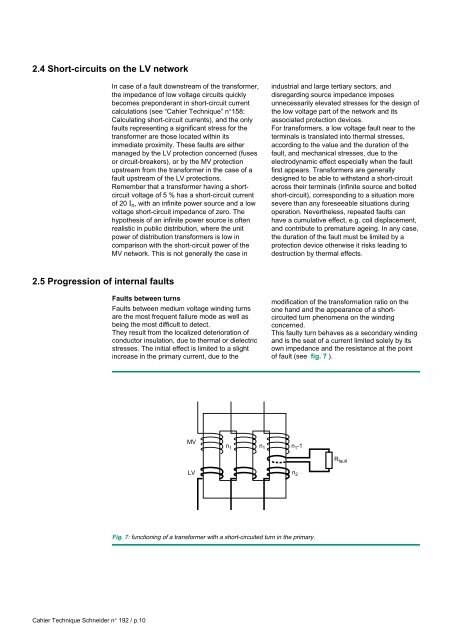
They result from the localized deterioration of<br />
conductor insulation, due to thermal or dielectric<br />
stresses. The initial effect is limited to a slight<br />
increase in the primary current, due to the<br />
modification of the transformation ratio on the<br />
one hand and the appearance of a shortcircuited<br />
turn phenomena on the winding<br />
concerned.<br />
This faulty turn behaves as a secondary winding<br />
and is the seat of a current limited solely by its<br />
own impedance and the resistance at the point<br />
of fault (see fig. 7 ).<br />
MV<br />
n 1 n 1 n 1 -1<br />
R fault<br />
LV<br />
n 2<br />
Fig. 7: functioning of a transformer with a short-circuited turn in the primary.<br />
Cahier Technique Schneider n° 192 / p.10