

ECT192

You also want an ePaper? Increase the reach of your titles
YUMPU automatically turns print PDFs into web optimized ePapers that Google loves.
or magnetic effect, without current<br />
transformation.<br />
This is the case of many low voltage circuitbreakers,<br />
but the direct relays are also suitable<br />
to medium voltage devices. They are tending<br />
nevertheless to disappear, basically due to their<br />
simple nature, their mediocre accuracy and their<br />
limited adjustment capacity.<br />
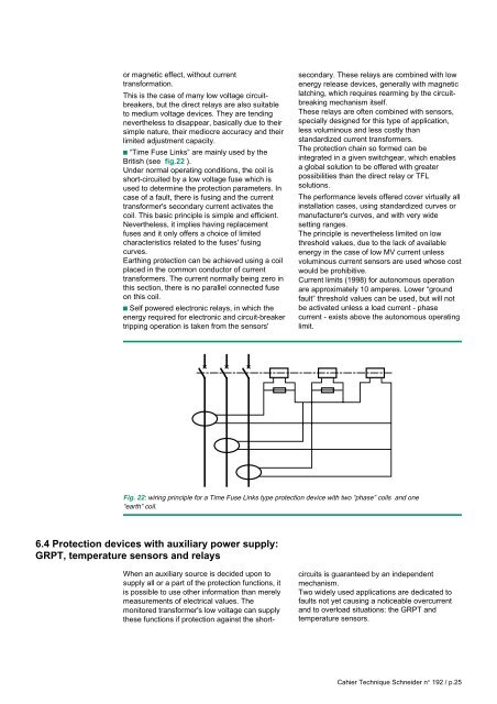
c “Time Fuse Links” are mainly used by the<br />
British (see fig.22 ).<br />
Under normal operating conditions, the coil is<br />
short-circuited by a low voltage fuse which is<br />
used to determine the protection parameters. In<br />
case of a fault, there is fusing and the current<br />
transformer's secondary current activates the<br />
coil. This basic principle is simple and efficient.<br />
Nevertheless, it implies having replacement<br />
fuses and it only offers a choice of limited<br />
characteristics related to the fuses' fusing<br />
curves.<br />
Earthing protection can be achieved using a coil<br />
placed in the common conductor of current<br />
transformers. The current normally being zero in<br />
this section, there is no parallel connected fuse<br />
on this coil.<br />
c Self powered electronic relays, in which the<br />
energy required for electronic and circuit-breaker<br />
tripping operation is taken from the sensors'<br />
secondary. These relays are combined with low<br />
energy release devices, generally with magnetic<br />
latching, which requires rearming by the circuitbreaking<br />
mechanism itself.<br />
These relays are often combined with sensors,<br />
specially designed for this type of application,<br />
less voluminous and less costly than<br />
standardized current transformers.<br />
The protection chain so formed can be<br />
integrated in a given switchgear, which enables<br />
a global solution to be offered with greater<br />
possibilities than the direct relay or TFL<br />
solutions.<br />
The performance levels offered cover virtually all<br />
installation cases, using standardized curves or<br />
manufacturer's curves, and with very wide<br />
setting ranges.<br />
The principle is nevertheless limited on low<br />
threshold values, due to the lack of available<br />
energy in the case of low MV current unless<br />
voluminous current sensors are used whose cost<br />
would be prohibitive.<br />
Current limits (1998) for autonomous operation<br />
are approximately 10 amperes. Lower “ground<br />
fault” threshold values can be used, but will not<br />
be activated unless a load current - phase<br />
current - exists above the autonomous operating<br />
limit.<br />
Fig. 22: wiring principle for a Time Fuse Links type protection device with two “phase” coils and one<br />
“earth” coil.<br />
6.4 Protection devices with auxiliary power supply:<br />
GRPT, temperature sensors and relays<br />
When an auxiliary source is decided upon to<br />
supply all or a part of the protection functions, it<br />
is possible to use other information than merely<br />
measurements of electrical values. The<br />
monitored transformer's low voltage can supply<br />
these functions if protection against the shortcircuits<br />
is guaranteed by an independent<br />
mechanism.<br />
Two widely used applications are dedicated to<br />
faults not yet causing a noticeable overcurrent<br />
and to overload situations: the GRPT and<br />
temperature sensors.<br />
Cahier Technique Schneider n° 192 / p.25