

ECT192

Create successful ePaper yourself
Turn your PDF publications into a flip-book with our unique Google optimized e-Paper software.
Prohibited operating points<br />
c The “prohibited” operating zone for “back-up”<br />
fuses extends from the rated current to the<br />
minimal breaking current. In this zone, two<br />
successive behaviours can be observed:<br />
v between the rated current and the minimal<br />
melting current, the excessive temperature rises<br />
can damage the fuse envelope and its<br />
environment within the switchgear;<br />
v between the minimal melting current and the<br />
minimal breaking current an arc appears that<br />
does not self-extinguish and which quickly leads<br />
to a major medium voltage fault if no other<br />
device intervenes.<br />
Because of this, these fuses must be used with<br />
care, only in applications in which the occurrence<br />
of a current of value located in this critical zone<br />
is impossible. If these fault situations are<br />
possible, it is necessary to use the fuse switch<br />
combination. This solution is discussed below.<br />
The selection guide, IEC 787, regarding fuse<br />
protection of transformers reviews the various<br />
criteria.<br />
c “Full range” fuses do not have a minimal<br />
breaking current. Their “prohibited” zone is<br />
therefore limited to the current values between<br />
the rated current and the minimal melting<br />
current, in order to comply with temperature rise<br />
limits. This is not a problematic zone except for<br />
semi-permanent phenomena which can lead to<br />
detrimental thermal effects. The order of<br />
magnitude of the time is one hour.<br />
c In transformer protection applications, faults<br />
are often progressive, based on low currents.<br />
This type of fault can subject the protection<br />
device to a current that very gradually increases<br />
beyond the rated current. Such progression, in a<br />
circuit protected by fuses of whatever type can<br />
be considered as dangerous due to the fact that<br />
it will systematically take the fuse into the critical<br />
zone. A slowly progressing fault in the<br />
transformer, can result in failure of the device,<br />
through overheating or non-breaking of the fuse.<br />
E.g: a 400 kVA transformer at 11 kV is protected<br />
by back-up fuses with a 40 A rated current,<br />
according to the fuse manufacturer's selection<br />
guide, while the rated current of the transformer<br />
is 21 A. The melting curve for such a fuse<br />
shows a minimal melting current of<br />
approximately 100 A with a minimal breaking<br />
current of approximately 130 A. In the case of a<br />
fault between the primary turns, there is a high<br />
probability that this fuse will be required to<br />
handle a dangerous level of current, the minimal<br />
breaking current being to the order of 6 times the<br />
transformer's rated current.<br />
Single phase operation<br />
Assuming only one fuse melts, the transformer is<br />
then supplied by the two remaining phases.<br />
Depending on the transformer coupling, low<br />
voltage loads will observe a different situation.<br />
In the case of a delta-star coupling, two lowvoltage<br />
phases out of three will find themselves<br />
in a reduced voltage situation and the phase<br />
displacements no longer complied with.<br />
This situation is mainly harmful to three-phase<br />
motors, as well as single phase motors<br />
connected to the phases with reduced voltage.<br />
Other applications can also be affected by<br />
reduced voltage, e.g. relay beats or discharge<br />
lamps.<br />
Separation on a single phase is therefore most<br />
often a situation to be avoided and can be<br />
considered as being worse than a complete<br />
outage bv.<br />
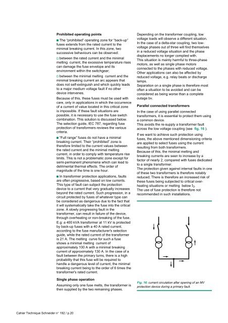
Parallel connected transformers<br />
In the case of using parallel connected<br />
transformers, it is essential to protect them using<br />
a common device.<br />
This avoids the re-supply a transformer fault<br />
across the low voltage coupling (see fig. 16 ).<br />
If we want to achieve such protection using<br />
fuses, the above mentioned dimensioning criteria<br />
are applied to select fuses using the current<br />
resulting from both transformers.<br />
Because of this, the minimal melting and<br />
breaking currents are seen to increase by a<br />
factor of nearly 2, compared with fuses dedicated<br />
to a single transformer.<br />
The protection given against internal faults in one<br />
of these two transformers is therefore notably<br />
reduced; There is therefore an increased risk of<br />
these fuses being subjected to critical overheating<br />
situations or melting below I 3 .<br />
The use of fuse protection is therefore not<br />
recommended in such installations.<br />
Fig. 16: current circulation after opening of an MV<br />
protection device during a primary fault.<br />
Cahier Technique Schneider n° 192 / p.20