Gunsof - NASA
Gunsof - NASA
Gunsof - NASA

You also want an ePaper? Increase the reach of your titles
YUMPU automatically turns print PDFs into web optimized ePapers that Google loves.
AMERICAN RIFLEMAN features guns of <strong>NASA</strong><br />
AMERICAN RIFLEMAN<br />
August 2003<br />
the<br />
Guns of<br />
<strong>NASA</strong><br />
The following article was written for American Rifleman nearly a<br />
year before the tragic February 1, 2003, Shuttle Columbia disaster.<br />
Now, <strong>NASA</strong> officials and the magazine staff hope its publication will<br />
illustrate for readers the importance of the agency’s many ongoing<br />
research programs aimed at promoting spaceflight mission safety.<br />
by William L. Ross, Sr., Donald Henderson and Claire G. Meador, Technical Editor,<br />
<strong>NASA</strong> Johnson Space Center White Sands Test Facility<br />
Photos courtesy of <strong>NASA</strong><br />
In the desert foothills where the<br />
six-guns and rifles of Pat Garrett,<br />
Billy the Kid and Geronimo once<br />
barked, the big guns of <strong>NASA</strong><br />
now thunder. Those figures of<br />
American history would have<br />
been awed at the size, power and<br />
purpose of <strong>NASA</strong>’s light-gas guns<br />
that send projectiles downrange<br />
at the speed of shooting stars. At<br />
a remote location northeast of Las<br />
Cruces, N.M., the rich legacy of<br />
the Wild West commingles with<br />
the modern Space Age at <strong>NASA</strong><br />
Johnson Space Center (JSC) White<br />
Sands Test Facility (WSTF) where<br />
a select group of technicians,<br />
engineers and scientists support<br />
Space Shuttle and International<br />
Space Station (ISS) missions by<br />
testing all materials used in the<br />
Space Program. Their primary<br />
responsibility is to promote and<br />
ensure Mission safety, of which<br />
the guns of <strong>NASA</strong> play a critical<br />
Reprinted with permission of the National Rifle Association of America, American Rifleman magazine, August 2003 issue<br />
A laser-illuminated<br />
shadow graph sequence<br />
of a 6 mm projectile (top,<br />
arrow) traveling at 23,000<br />
f.p.s. and its progressive<br />
impact, resulting in debris<br />
and ejecta cloud images.<br />
The first target plate is a<br />
bumper plate, 1/8”-thick<br />
6061-T6 aluminum. Stateof-the-art<br />
cameras shoot<br />
up to 48 exposures at<br />
framing rates up to 100<br />
million frames per second.<br />
AMERICAN RIFLEMAN<br />
August 2003
AMERICAN RIFLEMAN features guns of <strong>NASA</strong><br />
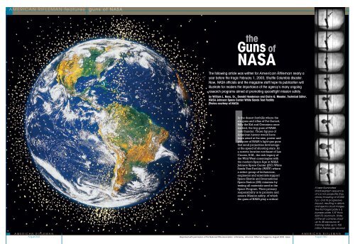
Previous page:<br />
An enhanced photo<br />
of Earth illustrates how<br />
the planet is continually<br />
bombarded from outer<br />
space by meteoroids.<br />
An orbiting layer of<br />
man-made debris, composed<br />
of spent rocket<br />
fragments, exploded<br />
satellites and other<br />
space mission bits and<br />
pieces, now join the naturally<br />
occurring meteoroids.<br />
These objects<br />
travel at hypervelocity<br />
speeds, by definition<br />
in excess of 6,600 f.p.s.,<br />
and are a significant<br />
threat to spacecraft during<br />
launch, orbit<br />
and re-entry operations.<br />
Safety is heavily<br />
emphasized at <strong>NASA</strong>.<br />
Attending personnel<br />
outside the 1” Light<br />
Gas Gun target tank<br />
(r.), which protrudes<br />
from the Hypervelocity<br />
Impact facility, wear<br />
protective suits<br />
equipped with<br />
breathing-air hoses.<br />
An astronaut working outside<br />
a vehicle in space is<br />
highly vulnerable to debris<br />
impacts, which is one<br />
reason <strong>NASA</strong> studies the<br />
effects of projectiles<br />
on various materials.<br />
role.<br />
For millions of years, Earth<br />
has been bombarded from outer<br />
space by meteoroids. An orbiting<br />
layer of man-made debris, composed<br />
of spent rocket fragments,<br />
exploded satellites and other<br />
space mission bits and pieces now<br />
join the naturally occurring meteoroids.<br />
Those objects travel at<br />
hypervelocity speeds—by definition<br />
in excess of 6,600 f.p.s.—and<br />
are a significant threat to spacecraft<br />
during launch, orbit and reentry<br />
operations.<br />
Space debris impacts are a<br />
real danger to astronauts doing<br />
extra-vehicular maneuvers and to<br />
high-pressure vessels and toxic aerospace<br />
materials carried aboard spacecraft.<br />
Traditionally, astronauts have<br />
faced these life- and mission-threatening<br />
dangers every time they went into<br />
space. Their defenses are much better<br />
now, with improved shielding and<br />
ballistic-quality windows that protect<br />
them from impacts caused by the<br />
smaller pieces of space debris.<br />
The Hypervelocity Group at WSTF<br />
works in close partnership with the<br />
JSC Hypervelocity Impact Technology<br />
Facility (HITF) in Houston. HITF determines<br />
the risk posed by space debris<br />
and designs spacecraft shields based<br />
1” Light Gas Gun Schematic<br />
This schematic diagram illustrates how <strong>NASA</strong>’s 1” light gas gun hurls tiny projectiles<br />
toward their target. The gun’s breech contains the first-stage charge of smokeless<br />
powder, set off by an electronic igniter, and upon exploding provides the rapidly<br />
expanding gas that drives the piston forward. The high-strength, heavy-wall pump<br />
tube contains the precision-machined plastic piston assembly that rapidly compresses<br />
the light gas column and provides the second-stage firing power. The taper-bored,<br />
high- pressure coupling halts the propelled piston at the end of its travel down the<br />
pump tube. In the HP section, rapid internal pressurization is followed by an extremely<br />
high level of impact caused by the halted piston. Upon petal-valve rupture, the sabot<br />
is launched—propelled by the rapidly expanding light gas—down the barrel into the<br />
expansion tank. The expansion tank allows collection and dissipation of second-stage,<br />
high-pressure light gas and permits the controlled separation of the sabot/projectile<br />
assembly. It is equipped with optical ports for in-flight photography of projectiles. The<br />
target tank is designed to contain resultant second-stage light gas and the eruption of<br />
shrapnel and debris from the impacted target. It, too, is equipped with optical ports.<br />
on probability of impact and spacecraft<br />
geometry. HITF builds and sends<br />
target shields to WSTF for ballisticlimit<br />
verification testing and then<br />
analyzes the results. Other spacecraft<br />
materials and components are also targeted,<br />
as well as toxic and explosive<br />
cargo including fuel (up to 5-lb. TNT<br />
equivalent).<br />
The WSTF Hypervelocity Impact<br />
(HVI) Testing Program assesses candidate<br />
shield materials using two-stage<br />
light-gas guns (LGG). These guns<br />
shoot projectiles at hypervelocities<br />
up to 24,000 f.p.s., roughly six times<br />
faster than the fastest rifle bullet, and<br />
mimic the impact of real space debris<br />
traveling at even higher speeds.<br />
The main LGG facility at WSTF<br />
houses 1”, .50- and .17-cal. guns.<br />
Because of the hazardous nature of<br />
the testing, the facility was built in a<br />
remote location, and the LGGs are<br />
remotely operated from underground<br />
Photo Lab Materials Preparation Machine Shop Component Services Metallurgy Lab Engineering Support<br />
A target assembly positioned in the<br />
outside target chamber indicates the<br />
projectile’s planned point of impact<br />
with a star-shaped cross.<br />
control bunkers. Television cameras<br />
constantly monitor the entire area.<br />
Access warning lights, signs and a<br />
remotely operated road gate control<br />
all possible area entry. Safety or<br />
warning announcements are broadcast<br />
before and after each shot. For<br />
non-hazardous testing, smaller .07-<br />
and .17-cal. guns are operated within<br />
another controlled-access laboratory.<br />
The two-stage LGG uses conventional<br />
smokeless gunpowder as its<br />
first stage. The second-stage propellant<br />
is a highly compressible light gas<br />
such as hydrogen. Since light gases<br />
have very low molecular weights,<br />
they can be more rapidly compressed<br />
to the high pressure levels needed to<br />
efficiently launch projectiles at hypervelocity<br />
speeds—usually from 8,000<br />
to 24,000 f.p.s.<br />
Hypervelocity LGG<br />
Operations Team<br />
AMERICAN RIFLEMAN AMERICAN RIFLEMAN<br />
August 2003<br />
August 2003
AMERICAN RIFLEMAN features guns of <strong>NASA</strong><br />
Projectile Cal.* Shape Material Wt. (grs.) Powder (grs.) Velocity (f.p.s.) Energy (ft.-lbs.)<br />
.17 cal. LGG<br />
1 mm (0.039”) Sphere Al** 0.02 71 22,900 23<br />
2 mm (0.078”) Sphere Al 0.18 71 22,500 202<br />
3 mm (0.117”) Sphere Al 0.55 77 22,600 624<br />
.17<br />
.50-cal. LGG<br />
Slug*** Nylon 0.92 80 24,900 1,270<br />
.17 Sphere Al 1.9 2,890 23,000 2,200<br />
.31 Sphere Al 11.3 2,920 22,900 13,200<br />
.41 Sphere Al 24.8 3,470 22,300 27,400<br />
.50<br />
1” LGG<br />
Slug Plastic 30.5 2,700 22,300 33,700<br />
.25 Sphere Al 5.8 19,140 23,100 6,900<br />
.50 Sphere Al 46.2 19,910 23,400 56,200<br />
.69 Sphere Al 120.0 22,380 21,700 125,000<br />
1.00 Slug Plastic 236.9 23,150 22,600 269,000<br />
* Actual or rounded to nearest caliber<br />
** Projectiles are typically aluminum alloy 2017-T4<br />
*** Flat-faced cylinder with a length-to-diameter ratio of about 1.0<br />
Depending on the gun and velocity<br />
required, smokeless powder charges<br />
range from 21 to 27,800 grs. (about 4<br />
lbs.). The smokeless charge propels<br />
a cylindrical polyethylene (plastic)<br />
piston at 2,500 f.p.s. down the “pump<br />
tube,” compressing the hydrogen gas.<br />
The piston enters the reduced taper<br />
bore of the high-pressure (HP) section<br />
and deforms in a rapid, energyabsorbing<br />
stop. A stainless steel petalvalve<br />
diaphragm retains the gas until it<br />
bursts under pressure, and the highly<br />
compressed (over 100,000 p.s.i.)<br />
hydrogen rapidly expands, accelerating<br />
the launch package down the barrel<br />
with little loss of energy. The hydrogen<br />
dissipates through the muzzle into<br />
an expansion tank. A stripper plate<br />
separates the launch package (sabot<br />
Results of a 1”x1”, 262.35-gr.<br />
Lexan slug having impacted<br />
a 3”-thick slab of aluminum<br />
at a velocity of 18,504 f.p.s.<br />
TYPICAL WSTF LGG BALLISTICS<br />
AMERICAN RIFLEMAN<br />
August 2003<br />
and projectile) while in free flight. The<br />
projectile then enters the evacuated<br />
target tank where it impacts the target.<br />
The projectile is photographed with<br />
high-speed cameras and flash X-rays<br />
just before impact. At times, the impacts<br />
are photographed to characterize the<br />
debris cloud. Three types of high-speed<br />
cameras are used. Cinema cameras run<br />
at 10,000 frames per second; 35 mm<br />
infrared cameras are capable of 2 million,<br />
and the digital cameras are capable<br />
of 100 million frames per second.<br />
Laser intervalometers measure<br />
projectile velocity. The time difference<br />
between interruption of laser beams by<br />
the projectile yields an extremely accurate<br />
calculation of its velocity—in the<br />
case of the 1” LGG, 23,000 f.p.s. in just<br />
22 ft. of barrel. In addition, high-speed<br />
data acquisition systems—using light<br />
detectors, strain gauges, pressure transducers,<br />
accelerometers and thermocouples—provide<br />
reliable diagnostics.<br />
The barrel—a long, high-strength<br />
section of steel with a precisionhoned<br />
smooth bore—allows for<br />
controlled acceleration of the propelled<br />
sabot/projectile assembly<br />
into the downstream expansion tank.<br />
A horizontal honing machine uses<br />
computer-controlled depth of cut,<br />
automatic fluid feed and a singlespindle<br />
14-stroke reciprocating/<br />
rotating-stone honing tool with various<br />
grit sizes. Before honing a new<br />
barrel, a plastic slug is fired to knock<br />
off the bore’s rough edges. Initial<br />
honing establishes the original LGG<br />
bore size. Subsequent honing cleans<br />
TYPICAL LGG CHARGES & IGNITERS<br />
Bore Size Powder Type Primer<br />
Shock waves<br />
travel through<br />
a solid aluminum<br />
target<br />
impacted by<br />
a projectile<br />
from the left,<br />
producing a<br />
blister (internal<br />
rupture) on the<br />
back face of<br />
the target.<br />
1” IMR 4831 Mark 27 torpedo igniter<br />
.50-cal. IMR 4198 Mark 27 torpedo igniter<br />
.17-cal. Alliant Unique CCI 209/solenoid firing pin<br />
.07-cal. Alliant Unique CCI 209/solenoid firing pin<br />
LIGHT GAS GUN SPECIFICATIONS<br />
Critical Dimensions & Bore Size<br />
Firing Pressure Ratings 1” .50-cal. .17-cal.<br />
Pump tube length (ft.) 80 40 4<br />
Barrel length (ft.) 22 12 2 to 3<br />
Target tank (ft. 3 ) 800 100 20<br />
Overall length (ft.) 175 85 29<br />
Breech pressure (p.s.i.) 3,800 3,000 7,300<br />
Piston velocity (f.p.s.) 2,500 2,200 3,000<br />
Petal valve burst pres. (p.s.i.) 5,000 10,000 2,500<br />
Barrel pres. (p.s.i.) 105,000 90,000 120,000 (est.)<br />
Actual projectiles encountered in space vary in size, shape<br />
and mass. The shape, size and material of LGG projectiles<br />
are standardized to obtain specific levels of impact energy.<br />
the bore and establishes the new<br />
bore size for the next sabot.<br />
LGG alignment is checked before<br />
every shot. A pedestal-mounted surveyor<br />
transit sights down the bore’s<br />
centerline from the open end of the<br />
LGG’s powder chamber (breech). The<br />
gun is bore-sighted, focusing the transit<br />
on various alignment plugs located<br />
at both ends of the pump tube and<br />
the barrel, and the HP section. LGG<br />
alignment is further verified by sighting<br />
on the stripper plate orifice in the<br />
expansion tank and finally on the premarked<br />
target itself. Accuracy for any<br />
of the WSTF LGG shots are normally<br />
within one projectile diameter of the<br />
marked point of impact on the target.<br />
The projectile/sabot launch package<br />
is carefully loaded into the entry<br />
end of the barrel. The petal valve<br />
and ring seal are inserted behind it,<br />
and the gun barrel assembly and HP<br />
section are clamped together with<br />
hydraulic collars. At the entrance end<br />
of the pump tube, a freezer-stored,<br />
ultrahigh-density 12-lb. polyethylene<br />
piston is inserted. The front face of<br />
the piston is a hollow cone that forms<br />
a gas seal as it compresses the hydrogen<br />
at a speed of about 2,500 f.p.s.<br />
The back end of the piston uses an<br />
O-ring to seal the expanding gases<br />
from the smokeless powder charge.<br />
Once the LGG is reassembled, a<br />
A simple multishock<br />
debris<br />
pattern (l.) is<br />
highly visible on<br />
the rear wall of<br />
a shield assembly.<br />
Kevlar and<br />
Nextel cloth<br />
in the second<br />
layer of another<br />
multi-shock shield<br />
assembly (bottom,<br />
l.) provide<br />
the same penetration<br />
resistance<br />
as aluminum, but<br />
are lighter. When<br />
impacted, the<br />
projectile melts<br />
and vaporizes.<br />
Impact comparisons on control media illustrate impact damage from a conventional<br />
.22 Mag. bullet (l.), 0.125” aluminum projectile (c.) and .22 LR bullet (r.).<br />
smokeless powder charge is inserted<br />
into the breech. A typical powder<br />
charge is about 18,500 grs. (2.6 lbs.)<br />
of IMR 4831 for the 1” LGG. Maximum<br />
charges use 4.1 lbs. An electrically<br />
activated standard Mark 27 torpedo<br />
igniter is contained in the center of<br />
the powder charge. The downstream<br />
barrel section, expansion tank and<br />
target tank are maintained at near<br />
vacuum in readiness for firing.<br />
Firing is performed from one of the<br />
underground control bunkers. Area<br />
TV surveillance monitors are checked<br />
to ensure that the area is secure, warning<br />
announcements are made and<br />
the bunker blast doors are secured<br />
to provide overpressure protection.<br />
The area warning lights are switched<br />
to red. The pump tube is remotely<br />
backfilled with hydrogen to 50 p.s.i.g.<br />
The firing circuit is turned on, and the<br />
X-ray system and high-speed cameras<br />
are activated. After a countdown, the<br />
“FIRE” button is pressed.<br />
The LGG, as with any other powder-charged<br />
gun, recoils upon firing.<br />
To accommodate that, the entire<br />
gun assembly is held within either<br />
anchored sleeves or sliding anchor<br />
assemblies, which allows the gun to<br />
move both forward and back. When<br />
the powder charge ignites, the normal<br />
recoil is counteracted when the<br />
forward-moving piston slams into the<br />
reduced taper HP section. The muzzle<br />
end of the barrel is sleeved into the<br />
expansion tank at the entry flange<br />
orifice with O-ring seals that accommodate<br />
movement in either direction.<br />
That linear recoil arrangement essentially<br />
isolates the anchored expansion<br />
and target tanks from any effects of<br />
recoil that could affect accuracy.<br />
The basic designs of WSTF LGGs<br />
originate from the 1940s and 1950s,<br />
Above are .50-cal. and 1” sabots in<br />
both assembled and separated modes.<br />
These highly engineered, precisionmachined<br />
plastic parts are designed<br />
to protect the projectile from barrel<br />
friction/abrasion and provide an effective<br />
gas seal up to the exit point into<br />
the expansion tank. Two petal valves,<br />
1” and .50-cal., are shown at left before<br />
and after shooting. The 304L stainless<br />
steel disks control the release of<br />
second-stage light gas.<br />
AMERICAN RIFLEMAN<br />
August 2003
guns of <strong>NASA</strong><br />
with improvements and updates<br />
made through the years. Most of<br />
the gun parts are made from highstrength,<br />
low-alloy steels, such as<br />
AISI 4340, with a minimum design<br />
yield strength of 140,000 p.s.i.<br />
Recently, the need for higherstrength<br />
materials was established to<br />
provide added safety, extended life<br />
and increased gun performance.<br />
In 2001, the Hypervelocity Group<br />
purchased some highly engineered<br />
Grade C250 maraging steel for a new<br />
.50-cal. HP section. It was supplied<br />
as a fully annealed, rough-turned<br />
custom forging. The critical taper<br />
bore was precision-machined using<br />
electron-discharge machining. After<br />
machining, the part was then heat<br />
treated to achieve its final properties.<br />
Test results indicate a yield strength<br />
of 285,000 p.s.i., twice the minimum<br />
design yield strength required for<br />
conventional gun steels used at WSTF.<br />
All gun components are thoroughly<br />
inspected and verified using ultrasonic<br />
testing, magnetic particle testing, X-ray,<br />
chemical analysis, Charpy V-notch, and<br />
tensile and hardness testing. A rigorous<br />
final dimensional inspection is also performed<br />
in strict accordance with <strong>NASA</strong><br />
design drawings.<br />
HVI testing at WSTF has contributed<br />
significantly to the design and<br />
evaluation of materials and shield configurations<br />
for the ISS, Space Shuttle,<br />
Extravehicular Mobility Unit (EMU),<br />
Long Duration Exposure Facility,<br />
Russian Space Station Mir, the X-38<br />
and the ISS-proposed Crew Return<br />
Vehicle. Because of the program’s<br />
success, the future of Hypervelocity<br />
Impact Testing will continue to include<br />
evaluation of new materials and concepts<br />
for the space program.<br />
<strong>NASA</strong> is currently evaluating the<br />
feasibility of manned missions to<br />
Mars. Although debris generated by<br />
man is not a problem once we are<br />
away from Earth, the threat of meteoroids<br />
with unknown velocities presents<br />
us with new challenges. Some<br />
estimates of velocities in our solar<br />
system are up to 230,000 f.p.s. Deepspace<br />
debris may travel even faster,<br />
up to approximately 787,000 f.p.s.<br />
New technology may emerge to<br />
enable scientists to more accurately<br />
predict the terminal ballistics of such<br />
super-high-velocity debris.<br />
For further information about WSTF<br />
and the HITF, visit: www.wstf.nasa.gov<br />
and www.hitf.jsc.nasa.gov.<br />
AMERICAN RIFLEMAN<br />
August 2003