a new aiming point for billiards - Illustrated Principles of Pool and ...
a new aiming point for billiards - Illustrated Principles of Pool and ...
a new aiming point for billiards - Illustrated Principles of Pool and ...

You also want an ePaper? Increase the reach of your titles
YUMPU automatically turns print PDFs into web optimized ePapers that Google loves.
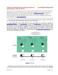
AN AIMING POINT METHOD FOR POOL<br />
Don Smith ddsmjs99@aol.com November, 2009<br />
A method is shown <strong>for</strong> determining where to aim the cue ball in pool. To use this method, the player must visualize two <strong>point</strong>s<br />
on the object ball <strong>and</strong> the distance between them. It is easy to learn <strong>and</strong> use, <strong>and</strong> may be particularly useful <strong>for</strong> those <strong>new</strong> to<br />
the game. This paper describes the method, called here the “Double The Distance” method or DTD.<br />
A brief description <strong>of</strong> the DTD is given first below, followed by further detail.<br />
SUMMARY OF THE DOUBLE THE DISTANCE METHOD (FIGURE 1)<br />
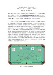
Finding the <strong>aiming</strong> <strong>point</strong> is a simple four-step process. Referring to Figure 1, these steps are:<br />
1. Find the <strong>point</strong> where a line from the cue ball will intersect the object ball.<br />
2. Find the <strong>point</strong> where a line from the pocket (or other target) will intersect the object ball.<br />
3. Estimate the distance between these two <strong>point</strong>s.<br />
4. Double this distance to find the <strong>aiming</strong> <strong>point</strong>.<br />
This usually takes 10-20 seconds.<br />
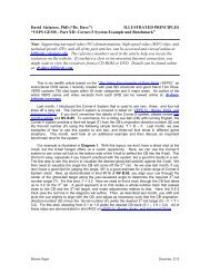
INTRODUCTION<br />
FIGURE 1. FIND THE AIMING POINT IN 4 EASY STEPS<br />
The discussion <strong>and</strong> diagrams given here assume a pocket <strong>billiards</strong> game like 8-ball or 9-ball. The DTD method can, however,<br />
be used <strong>for</strong> any <strong>billiards</strong> game. There can be pockets or not. The balls can be <strong>of</strong> any size. The object ball can be directed at<br />
any part <strong>of</strong> a pocket, at a <strong>point</strong> on the cushion, or at another ball. The cue ball <strong>and</strong> object ball can be anywhere on the table<br />
(with a modification described later, required when the cue <strong>and</strong> object balls are close together).<br />
The <strong>aiming</strong> <strong>point</strong> determined by this method does not include the effects <strong>of</strong> such factors as cue ball speed <strong>and</strong> English. The<br />
DTD provides a simple way <strong>of</strong> making a good first estimate <strong>of</strong> the <strong>aiming</strong> <strong>point</strong>. The effect <strong>of</strong> other factors must then be taken<br />
into account be<strong>for</strong>e taking the shot.<br />
1
The rest <strong>of</strong> this document gives:<br />
• A more complete description <strong>of</strong> the DTD method.<br />
• Examples.<br />
• The “ghost ball” alternative.<br />
• Finding the <strong>aiming</strong> <strong>point</strong> when the cue ball <strong>and</strong> object ball are close together.<br />
• Using “cue tip widths” <strong>for</strong> measuring the distance to the <strong>aiming</strong> <strong>point</strong>.<br />
• The theory on which the Double The Distance method is based.<br />
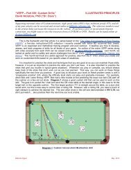
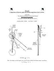
MORE COMPLETE DESCRIPTION OF THE DTD METHOD (FIGURE 2)<br />
FIGURE 2. MORE INFORMATION ABOUT THE DTD<br />
Step 1 <strong>of</strong> the DTD method, displayed in Figure 2, is to imagine a line from the center <strong>of</strong> the cue ball to the center <strong>of</strong> the object<br />
ball. This is line CO, which crosses the object ball at <strong>point</strong> U.<br />
In Step 2, the player visualizes a line from the object ball target, <strong>point</strong> T, through the center <strong>of</strong> the object ball O <strong>and</strong><br />
intersecting the outer edge <strong>of</strong> the object ball at <strong>point</strong> N. Point N is also the contact <strong>point</strong>, where the cue ball must strike the<br />
object ball in order to send the object ball to the target. Figure 2 also shows a <strong>point</strong> S, directly below N, on the line CN from<br />
the cue ball. Use <strong>of</strong> <strong>point</strong> S simplifies the discussions <strong>and</strong> figures given here.<br />
Step 3 is to visualize line US. The length <strong>of</strong> US is termed L.<br />
Finally, in Step 4, you imagine another line, extending from US <strong>and</strong> also <strong>of</strong> length L. The end <strong>of</strong> this line is the <strong>aiming</strong> <strong>point</strong> A.<br />
The length <strong>of</strong> USA (!) is termed D.<br />
If the cue ball is now stroked along line CA to the <strong>aiming</strong> <strong>point</strong> A, it will strike the object ball at <strong>point</strong> N. The object ball will then<br />
(we all hope) go into the pocket (or wherever you wished). If it does not, the most common cause is that the length <strong>of</strong> L was<br />
underestimated. It is better to estimate L a little long, thus <strong>aiming</strong> further away from the object ball. This is equivalent to<br />
assuming the cut angle is slightly greater than it appears.<br />
2
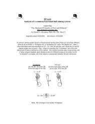
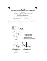
EXAMPLES (FIGURE 3)<br />
In Diagram #1 <strong>of</strong> Figure 3, the cut angle is 30º. With this cut, the <strong>aiming</strong> <strong>point</strong> A, from the player’s perspective, is located very<br />
close to the edge <strong>of</strong> the object ball. This is a <strong>for</strong>tunate location, since <strong>aiming</strong> at an edge is easier than <strong>aiming</strong> at a <strong>point</strong> inside<br />
or outside the object ball. If the cut is greater then 30º, the <strong>aiming</strong> <strong>point</strong> will be outside the object ball. Cuts <strong>of</strong> less than 30º<br />
result in <strong>aiming</strong> <strong>point</strong>s inside the object ball.<br />
The example <strong>of</strong> Diagram #2 has a 20º cut, <strong>and</strong> an <strong>aiming</strong> <strong>point</strong> slightly inside the object ball.<br />
Diagram #3 displays a fine cut, 12º. It can be difficult to locate a clear <strong>aiming</strong> <strong>point</strong> <strong>for</strong> fine cuts because the distances L <strong>and</strong> D<br />
are short, short distances are hard to estimate, <strong>and</strong> if an error is made in estimating the length <strong>of</strong> a short line, that error will be<br />
magnified when taking the shot.<br />
In Diagram #4 the cut is even finer, 6º. The best approach <strong>for</strong> playing fine cuts may be to memorize the cut <strong>and</strong> resulting<br />
<strong>aiming</strong> <strong>point</strong> <strong>of</strong> an example or two, then modify the shot at h<strong>and</strong> accordingly. Diagrams #3 <strong>and</strong> #4 provide c<strong>and</strong>idate<br />
examples.<br />
With a 45º cut, as in Diagram #5, the <strong>aiming</strong> <strong>point</strong> is outside the object ball. The normal DTD approach is to estimate the<br />
location <strong>of</strong> the <strong>aiming</strong> <strong>point</strong> then remember A <strong>for</strong> later in the shot setup routine. There is another approach to remembering A,<br />
shown in Diagrams # 5 <strong>and</strong> #6. In this alternate approach, you remember the distance to the <strong>aiming</strong> <strong>point</strong> from the edge <strong>of</strong> the<br />
object ball rather than the center. This “edge-length” is termed H in Diagrams #5 <strong>and</strong> #6.<br />
FIGURE 3. EXAMPLES OF THE DTD AIMING POINT FOR VARIOUS CUT ANGLES<br />
3
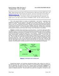
THE “GHOST BALL” ALTERNATIVE (FIGURE 4)<br />
A number <strong>of</strong> authors have described a method <strong>for</strong> <strong>aiming</strong> that employs a “ghost ball.” (See, <strong>for</strong> example, David G. Alciatore,<br />
“The <strong>Illustrated</strong> <strong>Principles</strong> <strong>of</strong> <strong>Pool</strong> <strong>and</strong> Billiards,” Sterling Publishing Co. Inc., New York, 2004, pp. 33, 35, 256.) Later sections<br />
<strong>of</strong> this DTD document refer to the ghost ball method, so a brief discussion is also given below.<br />
Figure 4 displays the Ghost Ball Method <strong>for</strong> locating the <strong>aiming</strong> <strong>point</strong>. In this method, a ball is imagined placed tangent to the<br />
object ball, with the ghost ball center G on the line from the target T through the center <strong>of</strong> the object ball O. The cue ball<br />
should be struck along a line from the cue ball through the ghost ball center. This will cause the cue ball to occupy the<br />
position held by the ghost ball, striking the object ball at N, <strong>and</strong> pocketing the object ball.<br />
An altered <strong>for</strong>m <strong>of</strong> the ghost ball method is <strong>for</strong> the player to change position temporarily to a <strong>point</strong> C’ on the line NC’. Here the<br />
player’s line <strong>of</strong> sight is perpendicular to line ON, from where it may be simpler to visualize the ghost ball center. However, the<br />
player must then change position again to view the table from behind the cue ball. This second move may make it difficult to<br />
remember the <strong>aiming</strong> <strong>point</strong> previously determined.<br />
It is difficult <strong>for</strong> some players to visualize the ghost ball <strong>and</strong> its center, particularly as the cue <strong>and</strong> object balls become distant<br />
from each other. For this reason, alternatives have been developed (such as the DTD). Some observations about the ghost<br />
ball are: (1) the center <strong>of</strong> the ghost ball is the best possible initial <strong>aiming</strong> <strong>point</strong>; <strong>and</strong> (2) an <strong>aiming</strong> <strong>point</strong> developed by any<br />
method (such as the DTD) must be on a line from the cue ball through the ghost ball center.<br />
FIGURE 4. AIMING WITH THE AID OF A GHOST BALL<br />
4<br />
C’
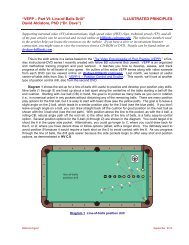
FINDING THE AIMING POINT WHEN THE CUE BALL AND OBJECT BALL ARE CLOSE TOGETHER (FIGURE 5)<br />
The DTD method assumes that the three lines from the cue ball towards the object ball, CO, CN, <strong>and</strong> CG from Diagram 1 <strong>of</strong><br />
Figure 5, are parallel. They are not, <strong>of</strong> course, although from some distance away they appear to be.<br />
Early in DTD development, a series <strong>of</strong> scale drawings was prepared to determine the effect <strong>of</strong> this assumption upon DTD<br />
accuracy. These drawings showed that the distance between the cue ball <strong>and</strong> object ball affect the “basic” DTD only when<br />
these two balls are 15” or less apart. Figure 5 displays such a situation.<br />
In this figure, the cue <strong>and</strong> object balls are a scaled distance <strong>of</strong> 6” apart. Point A prime (A’) is the <strong>aiming</strong> <strong>point</strong> determined by<br />
the DTD. Point A is the true <strong>aiming</strong> <strong>point</strong>, on an extension <strong>of</strong> line CG through the center <strong>of</strong> the ghost ball. The <strong>aiming</strong> error E<br />
using the basic DTD is the distance between A <strong>and</strong> A’. The error is well over ¼” in this example, much too large <strong>for</strong> an<br />
accurate shot. In this circumstance, a modified <strong>for</strong>m <strong>of</strong> the DTD must be used.<br />
FIGURE 5. USING A MODIFIED DTD WHEN THE CUE AND OBJECT BALLS ARE CLOSE TOGETHER<br />
Referring again to Figure 5, in the modified DTD method the player no longer estimates the length L then doubles it. Instead,<br />
the player estimates the length <strong>of</strong> line ON, (the radius <strong>of</strong> the object ball). The player then doubles this distance, along the line<br />
ON, to find the <strong>aiming</strong> <strong>point</strong> G - the center <strong>of</strong> the ghost ball. (Note that this process is essentially the same as using the ghost<br />
ball method described earlier.)<br />
Estimating the location <strong>of</strong> <strong>point</strong> G is difficult <strong>for</strong> some. Thus, players may prefer to use some other approach when the cue<br />
<strong>and</strong> object balls are close together. However, one strong advantage <strong>of</strong> using the modified DTD described here is that this<br />
approach will always work, regardless <strong>of</strong> the proximity <strong>of</strong> the cue <strong>and</strong> object balls. When distances between these two balls<br />
exceed 15”, the basic <strong>and</strong> modified DTD approaches become equivalent.<br />
5
USING “CUE TIP WIDTHS” TO REMEMBER THE AIMING POINT LOCATION (FIGURE 6)<br />
A useful approach <strong>for</strong> measuring distances from the object ball center <strong>and</strong> edge to the <strong>aiming</strong> <strong>point</strong> was discovered during<br />
DTD development. In this approach, distances are measured using the width <strong>of</strong> a cue tip as the basis. Diagram #1 <strong>of</strong> Figure<br />
6 displays the concept, where W is the cue tip width (using the average width <strong>of</strong> ½”). In Diagram #1 the <strong>aiming</strong> <strong>point</strong> A is 2-¼<br />
cue tips away.<br />
In Diagram #2, <strong>point</strong> N is about ¾ cue tips from the object ball center. A is a bit over 1-½ cue tips away.<br />
Diagram #3 shows a fine cut example. Here the <strong>aiming</strong> <strong>point</strong> is exactly 1 cue tip away, a good example to memorize. An<br />
even finer cut is shown in Figure #4. Here the intersection <strong>point</strong> N is ¼ <strong>of</strong> a cue tip away, so the <strong>aiming</strong> <strong>point</strong> A will be at ½ a<br />
cue tip.<br />
The examples <strong>of</strong> Diagrams #5 <strong>and</strong> #6 contain large cuts, 45º <strong>and</strong> 60º respectively. In these examples, it may be simpler to<br />
remember the number <strong>of</strong> cue tips from the edge <strong>of</strong> the object ball to A, termed H. H is ⅞ <strong>of</strong> a cue tip in Diagram #5, about 1-½<br />
cue tips in Diagram #6.<br />
FIGURE 6. USE OF “CUE TIP WIDTHS” FOR MEASURING DISTANCES<br />
6
THEORY (FIGURE 7)<br />
Figure 7 displays the object ball, the ghost ball, <strong>and</strong> labeled <strong>point</strong>s defined in previous figures. Also constructed are: (1)<br />
additional <strong>point</strong>s (upper case letters, as be<strong>for</strong>e), (2) lines between <strong>point</strong>s, <strong>and</strong> (3) angles (lower case letters). Two triangles<br />
are frequently referenced here, the larger <strong>for</strong>med by the three <strong>point</strong>s GOK, <strong>and</strong> the smaller by <strong>point</strong>s GNM.<br />
The relation that must be developed be<strong>for</strong>e the DTD can be accepted as valid is: the distance L, defined by the two object ball<br />
intersection <strong>point</strong>s U <strong>and</strong> N, when extended another length L, define the location <strong>of</strong> the <strong>aiming</strong> <strong>point</strong> A.<br />
From Figure 7, this relation can be stated as US = L <strong>and</strong> UA = 2L = D. An equivalent relation, <strong>and</strong> the one that will be shown<br />
as valid here, is: JN x 2 = KG.<br />
Major steps in the validity process follow. Some steps readily determined from the figure are omitted. (The validity <strong>of</strong> the<br />
method previously described as a “modified DTD” is clear from inspection <strong>of</strong> Figure 7, as the radius <strong>of</strong> both balls is the same.)<br />
1. Triangles GOK <strong>and</strong> GNM are both right triangles.<br />
2. The <strong>aiming</strong> <strong>point</strong> A is on a line from the cue ball through the ghost ball center.<br />
3. Angle a = angle a’, <strong>and</strong> b = b’. (Line GO intersects parallel lines.)<br />
4. The two triangles GOK <strong>and</strong> GNM are proportional. (The three angles <strong>of</strong> one <strong>of</strong> the triangles are equal to the same<br />
angles in the other triangle. As a result, the length <strong>of</strong> each <strong>of</strong> the three sides <strong>of</strong> one triangle are proportional to the<br />
corresponding sides <strong>of</strong> the other.)<br />
5. The distance GO is twice the length <strong>of</strong> NO.<br />
6. JN x 2 = GK. (True because the two triangles containing these lines are proportional <strong>and</strong> the line GO is 2 x the<br />
length <strong>of</strong> line NO.) The necessary DTD relation is valid.<br />
_________________________<br />
Copyright © 2009 by Don Smith<br />
FIGURE 7. THEORY<br />
7