Electro-Pneumatic Positioner TZIDC - Flowtec Industrietechnik GmbH.
Electro-Pneumatic Positioner TZIDC - Flowtec Industrietechnik GmbH.
Electro-Pneumatic Positioner TZIDC - Flowtec Industrietechnik GmbH.

You also want an ePaper? Increase the reach of your titles
YUMPU automatically turns print PDFs into web optimized ePapers that Google loves.
Data Sheet<br />
10/18-0.22-EN<br />
Pos:<br />
1 /Titelblätter / Copyright/DB/Aktorik/Stellungsregler/Elektropneumatischer Stellungsregler <strong>TZIDC</strong> @ 7\mod_1173176257644_3101.doc @ 71095 @<br />
Low operating cost<br />
Compact design<br />
Well-proven technology<br />
Robust and environmentally ruggedized<br />
Wide operating temperature range<br />
-40 ... 85 °C (-40 ... 185 °F)<br />
Easy to commission, “single pushbutton”<br />
operating philosophy<br />
Mechanical position indicator<br />
ATEX, FM, CSA, GOST and IECEx approvals<br />
For SIL2 safety loops<br />
Pos: 2 /Inhaltsverzeichnis/Inhaltsverzeichnis für alle Dokumente @ 0\mod_1138710310890_3101.doc @ 3129 @<br />
Contents<br />
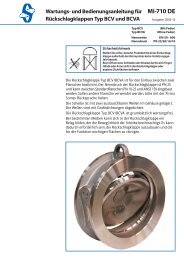
<strong>Electro</strong>-<strong>Pneumatic</strong> <strong>Positioner</strong><br />
<strong>TZIDC</strong><br />
for 4 … 20 mA two-wire technology<br />
Compact, well-proven, and flexible
<strong>Electro</strong>-<strong>Pneumatic</strong> <strong>Positioner</strong> <strong>TZIDC</strong> 10/18-0.22-EN<br />
for 4 … 20 mA two-wire technology<br />
Contents<br />
1 Description...........................................................................................................................................................3<br />
2<br />
1.1 <strong>Pneumatic</strong>s.....................................................................................................................................................3<br />
1.2 Operation........................................................................................................................................................3<br />
1.3 Communication ..............................................................................................................................................3<br />
1.4 Inputs and outputs..........................................................................................................................................3<br />
1.5 Modular design...............................................................................................................................................3<br />
2 Mounting versions...............................................................................................................................................5<br />
2.1 To linear actuators in accordance with the standard .....................................................................................5<br />
2.2 To rotary actuators in accordance with the standard .....................................................................................5<br />
2.3 Integral mounting to control valves ................................................................................................................5<br />
2.4 Special actuator-specific mounting ................................................................................................................5<br />
3 Operation..............................................................................................................................................................7<br />
3.1 General...........................................................................................................................................................7<br />
3.2 Operator panel ...............................................................................................................................................8<br />
4 Communication ...................................................................................................................................................9<br />
4.1 DTM................................................................................................................................................................9<br />
4.2 LKS adapter (RS-232 interface converter).....................................................................................................9<br />
4.3 FSK Modem ...................................................................................................................................................9<br />
5 Technical data....................................................................................................................................................10<br />
5.1 Input..............................................................................................................................................................10<br />
5.2 Output...........................................................................................................................................................10<br />
5.3 Travel............................................................................................................................................................10<br />
5.4 Air supply......................................................................................................................................................10<br />
5.5 Transmission data and influences................................................................................................................10<br />
5.6 Environmental capabilities ...........................................................................................................................11<br />
5.7 Housing ........................................................................................................................................................11<br />
5.8 Safety Integrity Level....................................................................................................................................11<br />
5.9 Explosion protection.....................................................................................................................................12<br />
5.10 Options .........................................................................................................................................................13<br />
5.11 Accessories ..................................................................................................................................................14<br />
6 Electrical connections ......................................................................................................................................15<br />
7 Dimensions ........................................................................................................................................................17<br />
8 Ordering information.........................................................................................................................................20<br />
8.1 Accessories ..................................................................................................................................................22
<strong>Electro</strong>-<strong>Pneumatic</strong> <strong>Positioner</strong> <strong>TZIDC</strong> 10/18-0.22-EN<br />
for 4 … 20 mA two-wire technology<br />
Pos: 3.1 /Überschriften/1/J - L/Kurzbeschreibung @ 7\mod_1175676881796_3101.doc @ 75993 @ 11<br />
1 Description<br />
P os: 3.2 /==== Wechsel ein- auf zweispaltig ==== @ 0\mod_1130421847171_3101.doc @ 3828 @<br />
Change from one to two columns<br />
P os: 3.3 /Technische Daten / Datenblatt/Aktorik/Stellungsregler/Allgemein/Kurzbeschreibung/Kurzbeschreibung @ 10\mod_1173180169769_3101.doc @ 71118 @<br />
The <strong>TZIDC</strong> is an electronically configurable positioner with<br />
communication capabilities designed for mounting to pneumatic<br />
linear or rotary actuators. It features a small and compact design, a<br />
modular construction, and an excellent cost-performance ratio.<br />
Fully automatic determination of the control parameters and<br />
adaptation to the final control element yield considerable time savings<br />
and an optimal control behavior.<br />
Pos:<br />
3.4 /Überschriften/1.1/2-spaltig/P - R/Pneumatik @ 10\mod_1176211138453_3101.doc @ 76683 @ 22<br />
1.1 <strong>Pneumatic</strong>s<br />
Pos:<br />
3.5 /Technische Daten / Datenblatt/Aktorik/Stellungsregler/Allgemein/Kurzbeschreibung/Pneumatik (2009-02-13 08:14:33) @ 10\mod_1173180645393_3101.doc @ 71139 @<br />
a<br />
An I/P module with subsequent pneumatic amplifier is used to control<br />
the pneumatic actuator. The well-proven I/P module proportionally<br />
converts the permanent electrical positioning signal from the CPU<br />
into a pneumatic signal used to adjust a 3/3-way valve.<br />
The air flow for pressurizing or depressurizing the actuator is<br />
continuously adjusted. As a result, excellent control is achieved.<br />
When reaching the set point, the 3/3-way valve is closed in center<br />
position to minimize the air consumption.<br />
Four different pneumatics versions are available: for single-acting or<br />
double-acting actuators, each with “fail-safe” or “fail-freeze” function.<br />
Pos:<br />
3.6 /Überschriften/1.1.1/2-spaltig/Sicherheitsfunktion "entlüftend" @ 10\mod_1176211744343_3101.doc @ 76809 @ 33<br />
1.1.1 “Fail-safe” function<br />
P os: 3.7 /Technische Daten / Datenblatt/Aktorik/Stellungsregler/Allgemein/Kurzbeschreibung/Sicherheitsfunktion "entlüftend" (2009-02-13 08:16:51) @ 10\mod_1176211673796_3101.doc @ 76788 @<br />
If the electrical power supply fails, the positioner output 1 is<br />
depressurized, and the pneumatic actuator’s return spring moves the<br />
valve to the defined safe position. In case of a double-acting actuator<br />
the second output 2 is additionally pressurized.<br />
Pos:<br />
3.8 /======= Spaltenumbruch ======== @ 0\mod_1132937966324_3101.doc @ 3831 @<br />
Change from one to two columns<br />
Pos:<br />
3.20 /======= Seitenumbruch ======== @ 0\mod_1126532365768_3101.doc @ 3830 @<br />
Pos:<br />
3.9 /Überschriften/1.1.1/2-spaltig/Sicherheitsfunktion "blockierend" @ 10\mod_1176211798765_3101.doc @ 76830 @ 33<br />
1.1.2 “Fail-freeze” function<br />
Pos:<br />
3.10 /Technische Daten / Datenblatt/Aktorik/Stellungsregler/Allgemein/Kurzbeschreibung/Sicherheitsfunktion "blockierend" (2009-02-13 08:16:41) @ 10\mod_1176211845484_3101.doc @ 76851 @<br />
If the electrical power supply should fail, the positioner output 1 (and<br />
2, if applicable) is closed and the pneumatic actuator stops<br />
(“freezes”) the valve in the current position. If compressed air supply<br />
should fail, the positioner depressurizes the actuator.<br />
Pos:<br />
3.11 /Überschriften/1.1/2-spaltig/A - C/Bedienung @ 10\mod_1176211172234_3101.doc @ 76704 @ 22<br />
1.2 Operation<br />
Pos:<br />
3.12 /Technische Daten / Datenblatt/Aktorik/Stellungsregler/Allgemein/Kurzbeschreibung/Bedienung (Kommunikationsmöglichkeit) (2009-02-13 08:24:30) @ 10\mod_1173184631054_3101.doc @ 71160 @<br />
The positioner has a built-in operating panel providing a 2-line LCD<br />
and 4 pushbuttons for optimal local configuration, commissioning and<br />
operational monitoring.<br />
Alternatively, the appropriate configuration program and the available<br />
communication option can be used.<br />
Pos:<br />
3.13 /Überschriften/1.1/2-spaltig/J - L/Kommunikation @ 10\mod_1176211201546_3101.doc @ 76725 @ 22<br />
1.3 Communication<br />
Pos:<br />
3.14 /Technische Daten / Datenblatt/Aktorik/Stellungsregler/<strong>TZIDC</strong> / <strong>TZIDC</strong>-200/Kurzbeschreibung/Kommunikation @ 10\mod_1176212225390_3101.doc @ 76893 @<br />
The standard <strong>TZIDC</strong> model has a local communication interface (LKS<br />
connector). Additionally, a “HART communication” option for<br />
communication via the 20 mA signal is available. Both<br />
communications are based on the HART Protocol.<br />
Pos:<br />
3.15 /Überschriften/1.1/2-spaltig/D - F/Ein-/Ausgänge @ 10\mod_1176211233015_3101.doc @ 76746 @ 22<br />
1.4 Inputs and outputs<br />
Pos:<br />
3.16 /Technische Daten / Datenblatt/Aktorik/Stellungsregler/<strong>TZIDC</strong> / <strong>TZIDC</strong>-200/Kurzbeschreibung/Ein-/Ausgänge @ 10\mod_1176212290390_3101.doc @ 76914 @<br />
In addition to its input for the analog position set point the <strong>TZIDC</strong><br />
positioner is equipped with a digital input which can be used to<br />
activate various protective functions in the device via the process<br />
control system. A digital output allows you to output collective alarms<br />
or fault messages.<br />
Pos:<br />
3.17 /Überschriften/1.1/2-spaltig/M - O/Modularer Aufbau @ 10\mod_1176211317984_3101.doc @ 76767 @ 22<br />
1.5 Modular design<br />
Pos:<br />
3.18 /Technische Daten / Datenblatt/Aktorik/Stellungsregler/Allgemein/Kurzbeschreibung/ModularerAufbau @ 10\mod_1173184783043_3101.doc @ 71181 @<br />
q<br />
The<strong>TZIDC</strong> basic model can be enhanced at any time by retrofitting<br />
optional equipment. Option modules for analog or digital position<br />
feedback or a shutdown-module can be installed. Additionally, a<br />
mechanical position indicator, proximity switches or 24 V<br />
microswitches are available for indicating the position independently<br />
of the mother board function.<br />
Pos:<br />
3.19 /==== Wechsel zwei- auf einspaltig ==== @ 0\mod_1130421955859_3101.doc @ 3829 @<br />
3
<strong>Electro</strong>-<strong>Pneumatic</strong> <strong>Positioner</strong> <strong>TZIDC</strong> 10/18-0.22-EN<br />
for 4 … 20 mA two-wire technology<br />
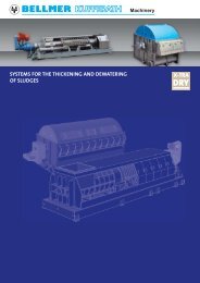
Pos: 3.21 /Technische Daten / Datenblatt/Aktorik/Stellungsregler/<strong>TZIDC</strong> / <strong>TZIDC</strong>-200/Kurzbeschreibung/Schematische Darstellung @ 10\mod_1173185518080_3101.doc @ 71202 @<br />
Basic model Optional upgrades<br />
Fig. 1: <strong>TZIDC</strong> schematic diagram<br />
Basic model Optional upgrades<br />
1 LKS plug<br />
9 Plug module for analog feedback (4 … 20 mA)<br />
2 Positioning signal 4 … 20 mA<br />
10 Plug-in module for safety shutdown (forced depressurization)<br />
3 Digital input<br />
11 Plug module for digital feedback<br />
4 Digital output DO<br />
12 Installation kit for mechanical position indicator<br />
5 Supply, 1.4 … 6 bar (20 ... 90 psi)<br />
13 Installation kit for digital feedback with proximity switches<br />
6 Exhaust<br />
14 Installation kit for digital feedback with 24 V microswitches<br />
7 I/P module with 3/3-way valve<br />
8 Position sensor (optional up to 270° rotation angle)<br />
Pos:<br />
4 /======= Seitenumbruch ======== @ 0\mod_1126532365768_3101.doc @ 3830 @<br />
4<br />
Important<br />
With optional upgrades either the “Installation kit for digital feedback with proximity switches” (13) or the “Installation<br />
kit for digital feedback with microswitches 24 V” (14) can be used.<br />
In both cases, the “mechanical position indicator” (8) must be installed.
<strong>Electro</strong>-<strong>Pneumatic</strong> <strong>Positioner</strong> <strong>TZIDC</strong> 10/18-0.22-EN<br />
for 4 … 20 mA two-wire technology<br />
Pos: 5.1 /Überschriften/1/A - C/Anbauversionen @ 9\mod_1180950395125_3101.doc @ 101275 @ 11<br />
2 Mounting versions<br />
P os: 5.2 /==== Wechsel ein- auf zweispaltig ==== @ 0\mod_1130421847171_3101.doc @ 3828 @<br />
Change from one to two columns<br />
P os: 5.3 /Überschriften/1.1/2-spaltig/G - I/Genormter Anbau an pneumatische Linearantriebe @ 10\mod_1176212852312_3101.doc @ 76956 @ 22<br />
2.1 To linear actuators in accordance with the<br />
standard<br />
Pos:<br />
5.4 /Technische Daten / Datenblatt/Aktorik/Stellungsregler/Allgemein/Montage/Genormter Anbau an pneumatische Linearantriebe (2009-02-13 13:36:46) @ 10\mod_1176213091968_3101.doc @ 77040 @<br />
Lateral attachment is in accordance with DIN / IEC 534 (lateral<br />
attachment to NAMUR). The required attachment kit is a complete<br />
set of attachment material, but does not include the screwed pipe<br />
connections and air pipes.<br />
Pos:<br />
5.5 /Überschriften/1.1/2-spaltig/G - I/Genormter Anbau an pneumatische Schwenkantriebe @ 10\mod_1176212899953_3101.doc @ 76977 @ 22<br />
2.2 To rotary actuators in accordance with the<br />
standard<br />
P os: 5.6 /Technische Daten / Datenblatt/Aktorik/Stellungsregler/Allgemein/Montage/Genormter Anbau an pneumatische Schwenkantriebe (2009-02-13 13:37:11) @ 10\mod_1176213146937_3101.doc @ 77061 @<br />
This attachment is designed for mounting according to the standard<br />
VDI/VDE 3845. The attachment kit consists of a console with<br />
mounting screws for mounting on a rotary actuator. The adapter for<br />
coupling the positioner feedback shaft to the actuator shaft has to be<br />
ordered separately. Screwed pipe connections and air pipes have to<br />
be provided on site.<br />
Pos: 5.7 /======= Spaltenumbruch<br />
======== @ 0\mod_1132937966324_3101.doc @ 3831 @<br />
Change from one to two columns<br />
Pos:<br />
5.13 /======= Seitenumbruch ======== @ 0\mod_1126532365768_3101.doc @ 3830 @<br />
Pos:<br />
5.8 /Überschriften/1.1/2-spaltig/G - I/Integrierter Anbau an Regelventile @ 10\mod_1176212940421_3101.doc @ 76998 @ 22<br />
2.3 Integral mounting to control valves<br />
Pos:<br />
5.9 /Technische Daten / Datenblatt/Aktorik/Stellungsregler/Allgemein/Montage/Integrierter Anbau an Regelventile, <strong>TZIDC</strong>-1x0 @ 10\mod_1176213402234_3101.doc @ 77103 @<br />
The <strong>TZIDC</strong> positioner featuring single acting pneumatic action is also<br />
suitable for integral mounting.<br />
The required holes are found at the back of the device.<br />
The benefit of this design is that the point for mechanical stroke<br />
measurement is protected and that the positioner and actuator are<br />
linked internally. No external tubing is required.<br />
Pos:<br />
5.10 /Überschriften/1.1/2-spaltig/A - C/Besondere antriebsspezifische Anbauversionen @ 10\mod_1176212991062_3101.doc @ 77019 @ 22<br />
2.4 Special actuator-specific mounting<br />
Pos:<br />
5.11 /Technische Daten / Datenblatt/Aktorik/Stellungsregler/Allgemein/Montage/Besondere antriebsspezifische Anbauversionen @ 10\mod_1173186727709_3101.doc @ 71265 @<br />
In addition to the mounting methods described above, there are<br />
special actuator-specific attachments.<br />
Please contact us for details.<br />
Pos:<br />
5.12 /==== Wechsel zwei- auf einspaltig ==== @ 0\mod_1130421955859_3101.doc @ 3829 @<br />
5
<strong>Electro</strong>-<strong>Pneumatic</strong> <strong>Positioner</strong> <strong>TZIDC</strong> 10/18-0.22-EN<br />
for 4 … 20 mA two-wire technology<br />
Pos: 5.14 /Technische Daten / Datenblatt/Aktorik/Stellungsregler/Allgemein/Montage/Anbauvarianten <strong>TZIDC</strong>-1x0 @ 10\mod_1173187335173_3101.doc @ 71286 @<br />
1<br />
2<br />
Fig. 2: Mounting options<br />
1 Mounting to linear actuators acc. to DIN / IEC 534<br />
2 Mounting to rotary actuators to VDI / VDE 3845<br />
Pos:<br />
6 /======= Seitenumbruch ======== @ 0\mod_1126532365768_3101.doc @ 3830 @<br />
6<br />
3<br />
4<br />
3 Integral mounting to control valves<br />
4 Integral mounting to control valves by using an adapter panel<br />
M00233
<strong>Electro</strong>-<strong>Pneumatic</strong> <strong>Positioner</strong> <strong>TZIDC</strong> 10/18-0.22-EN<br />
for 4 … 20 mA two-wire technology<br />
Pos: 7.1 /Überschriften/1/A - C/Betrieb @ 10\mod_1175678278921_3101.doc @ 76015 @ 11<br />
3 Operation<br />
P os: 7.2 /==== Wechsel ein- auf zweispaltig ==== @ 0\mod_1130421847171_3101.doc @ 3828 @<br />
Change from one to two columns<br />
Pos:<br />
7.3 /Überschriften/1.1/2-spaltig/A - C/Allgemeines @ 10\mod_1176213970765_3101.doc @ 77124 @ 22<br />
A<br />
3.1 General<br />
P os: 7.4 /Technische Daten / Datenblatt/Aktorik/Stellungsregler/Allgemein/Betrieb/Allgemeines @ 10\mod_1176214294328_3101.doc @ 77292 @<br />
Microprocessor-based position control in the <strong>TZIDC</strong> provides for<br />
optimal results. The positioner features high-precision control<br />
functions and high operational reliability. Due to their elaborate<br />
structure and easy accessibility, the device parameters can be<br />
quickly adapted to the respective application.<br />
Digital input<br />
For the digital input, one of the following safety options can be<br />
selected. You may use the operator’s panel or configuration program<br />
to select an option.<br />
- No function (default)<br />
- Move to 0 % position<br />
- Move to 100 % position<br />
The total range of parameters includes: - Hold previous position<br />
- Operating parameters - disable local configuration<br />
- Adjustment parameters - Disable local configuration and operation<br />
- Monitoring parameters - Disable any access (no local or remote access via a PC)<br />
- Diagnosis parameters The selected function is activated once the 24 V DC signal is no<br />
- Maintenance parameters<br />
longer applied (< 11 V DC).<br />
Pos:<br />
7.5 /Überschriften/1.1.1/2-spaltig/Betriebsparameter @ 10\mod_1176214001500_3101.doc @ 77145 @ 33<br />
3.1.1 Operating parameters Pos:<br />
P os: 7.6 /Technische Daten / Datenblatt/Aktorik/Stellungsregler/<strong>TZIDC</strong> / <strong>TZIDC</strong>-200/Betrieb/Betriebsparameter @ 10\mod_1176214346265_3101.doc @ 77343 @<br />
The following operating parameters can be set manually if required:<br />
Pos:<br />
7.7 /Überschriften/1.1.1/2-spaltig/Justageparameter @ 10\mod_1176214036515_3101.doc @ 77166 @ 33<br />
3.1.2 Adjustment parameters<br />
7.8 /Technische Daten / Datenblatt/Aktorik/Stellungsregler/<strong>TZIDC</strong> / <strong>TZIDC</strong>-200/Betrieb/Justageparameter @ 17\mod_1202462076828_3101.doc @ 156313 @<br />
The <strong>TZIDC</strong> positioner has a special function for automatic adjustment<br />
of the parameters.<br />
Additionally, the control parameters can be set automatically (in<br />
adaptive control mode) or manually to optimally adapt them to the<br />
process requirements.<br />
Signal<br />
Signal min. 4 mA, max. signal 20 mA (0 ... 100 %)<br />
freely selectable for split-range operation<br />
min. range 20 % (3.2 mA)<br />
recommended range > 50 % (8.0 mA)<br />
Tolerance band<br />
Upon reaching the tolerance band, the position is slowly re-adjusted<br />
Action (positioning signal)<br />
until the dead band has been reached.<br />
Increasing: Signal 4 ... 20 mA = position 0 ... 100 %<br />
Increasing: Signal 20 ... 4 mA = position 0 ... 100 %<br />
Dead band (sensitivity)<br />
When reaching the dead band, the position is held. The factory<br />
Characteristic curve (travel = f {signal})<br />
Linear, equal percentage 1:25 or 1:50 or 25:1 or 50:1 or freely<br />
setting for this parameter is 0,1 %.<br />
configurable with 20 reference points. Actuator spring action<br />
Travel limit<br />
The positioning travel, i.e. the stroke or angle of rotation, can be<br />
reduced as required within the full range of 0 ... 100 %, provided that<br />
a minimum value of 20 % is observed.<br />
Selection of the sensor shaft rotating sense (looking into the open<br />
case), if the valve is moved to the safe position by the actuator spring<br />
(actuator is depressurized via Y1 / OUT1).<br />
For double-acting actuators the actuator spring action corresponds to<br />
pressurizing the pneumatic output (OUT2).<br />
Shut-off function<br />
This parameter can be set separately for each end position. When<br />
the respective configured limit value is exceeded, the shut-off<br />
function causes immediate travel of the actuator until reaching the set<br />
Display 0 ... 100 %<br />
Adjusting the display (0 ... 100%) according to the direction of action<br />
for opening or closing the valve.<br />
end position.<br />
Pos:<br />
7.9 /Überschriften/1.1.1/2-spaltig/Betriebsüberwachungsparameter @ 10\mod_1176214071453_3101.doc @ 77187 @ 33<br />
When the shut-off value is set to “0”, the position is further controlled,<br />
even in the respective end position.<br />
3.1.3 Monitoring parameters<br />
/ / Pos: 7.10 /Technische Daten Datenblatt/Aktorik/Stellungsregler/<strong>TZIDC</strong> <strong>TZIDC</strong>-200/Betrieb/Betriebsüberwachungsparameter @ 10\mod_1176214447375_3101.doc @ 77385 @<br />
B<br />
Various functions for permanent operational monitoring are<br />
implemented in the <strong>TZIDC</strong> operating program. The following states<br />
Travel time prolongation<br />
This function can be used to increase the max. travel time for full will be detected and indicated, e.g.:<br />
travel. This time parameter can be set separately for each direction. - 4 ... 20 mA signal out of range<br />
Important<br />
- position out of the adjusted range<br />
This function can only be used with the pneumatics with the - positioning time-out (adjustable time parameter)<br />
safety function “fail-safe”.<br />
- position controller inactive<br />
Switching points for the position<br />
This parameter allows you to define two position limits for signaling<br />
(see option “Module for digital position feedback”).<br />
- counter limits (settable in the diagnosis phase) exceeded<br />
While automatic commissioning is in progress, the current state is<br />
continuously indicated on the integrated LCD.<br />
During operation, the LCD shows the most important process<br />
Digital output<br />
variables:<br />
The alarms generated in the <strong>TZIDC</strong> positioner can be polled via the - current position (in %),<br />
digital output as a collective alarm.<br />
- malfunctions, alarms, messages (as code)<br />
The desired information can be selected via the operator panel or<br />
remotely via the configuration program.<br />
The output can be set to “active high” or “active low”, as required.<br />
Access to extended monitoring parameters is possible via HART<br />
communication and the DTM.<br />
Pos:<br />
7.11 /======= Seitenumbruch ======== @ 0\mod_1126532365768_3101.doc @ 3830 @<br />
7
<strong>Electro</strong>-<strong>Pneumatic</strong> <strong>Positioner</strong> <strong>TZIDC</strong> 10/18-0.22-EN<br />
for 4 … 20 mA two-wire technology<br />
Pos:<br />
7.12 /Überschriften/1.1.1/2-spaltig/Diagnoseparameter @ 10\mod_1176214111046_3101.doc @ 77208 @ 33<br />
3.1.4 Diagnosis parameters<br />
P os: 7.13 /Technische Daten / Datenblatt/Aktorik/Stellungsregler/Allgemein/Betrieb/Diagnoseparameter @ 10\mod_1176214500906_3101.doc @ 77406 @<br />
The diagnosis parameters of the <strong>TZIDC</strong> program inform the operator<br />
about the operating conditions of the valve.<br />
From this information the operator can derive which maintenance<br />
works are required, and when.<br />
Additionally, limit values can be defined for these parameters. When<br />
they are exceeded, an alarm is reported.<br />
The following values are e.g. determined:<br />
- Number of movements performed by the valve<br />
- Total travel<br />
The diagnosis parameters and limit values can be called up, set, and<br />
reset via HART communication, using the configuration program.<br />
Pos:<br />
7.14 /Überschriften/1.1/2-spaltig/A - C/Bedienpanel @ 10\mod_1176214143953_3101.doc @ 77229 @ 22<br />
3.2 Operator panel<br />
P os: 7.15 /Technische Daten / Datenblatt/Aktorik/Stellungsregler/Allgemein/Betrieb/Bedienpanel <strong>TZIDC</strong>-1x0 @ 10\mod_1176214815500_3101.doc @ 77427 @<br />
The <strong>TZIDC</strong> positioner’s operator panel with four pushbuttons allows<br />
for<br />
- operational monitoring<br />
- manual control<br />
- configuration<br />
- fully automatic commissioning<br />
The operator panel is protected by a cover which avoids<br />
unauthorized access to the operating elements.<br />
Pos:<br />
7.16 /======= Spaltenumbruch ======== @ 0\mod_1132937966324_3101.doc @ 3831 @<br />
Change from one to two columns<br />
Pos: 7.22 /==== Leeres Modul mit einer Absatzmarke, DS, 1-spaltig ==== @ 2\mod_1153381574375_0.doc @ 35553 @<br />
Pos: 7.23 /==== Wechsel ein- auf zweispaltig ==== @ 0\mod_1130421847171_3101.doc @ 3828 @<br />
Change from one to two columns<br />
Pos: 7.24 /Technische Daten / Datenblatt/Aktorik/Stellungsregler/Allgemein/Betrieb/Abb. <strong>TZIDC</strong>, <strong>TZIDC</strong>-1x0 und Bedienelemente @ 10\mod_1175678693046_3101.doc @ 76035 @<br />
M00234<br />
Fig. 3: <strong>TZIDC</strong> with removed cover, view of the operator panel<br />
Change from one to two columns<br />
Pos:<br />
8 /======= Seitenumbruch ======== @ 0\mod_1126532365768_3101.doc @ 3830 @<br />
8<br />
Pos:<br />
7.17 /Überschriften/1.1.1/2-spaltig/Ein-Tasten-Inbetriebnahme @ 10\mod_1176214193156_3101.doc @ 77250 @ 33<br />
3.2.1 Single-button commissioning<br />
Pos:<br />
7.18 /Technische Daten / Datenblatt/Aktorik/Stellungsregler/<strong>TZIDC</strong> / <strong>TZIDC</strong>-200/Betrieb/Ein-Tasten-Inbetriebnahme @ 10\mod_1176214842843_3101.doc @ 77448 @<br />
Commissioning the <strong>TZIDC</strong> positioner is especially easy. The<br />
standard Autoadjust function for automatic adaptation of the device<br />
parameters can be started by simply pressing a single front panel<br />
button, and without knowing parameterization details.<br />
Depending on the selected actuator type (linear or rotary), the<br />
displayed zero position is automatically adapted:<br />
- for linear actuators counter-clockwise (CTCLOCKW)<br />
- for rotary actuators clockwise (CLOCKW).<br />
Besides this standard function, a customized “Autoadjust” function is<br />
available. The function is launched either via the operator’s panel or<br />
HART communication.<br />
Pos:<br />
7.19 /Überschriften/1.1.1/2-spaltig/Anzeigen @ 10\mod_1176214259859_3101.doc @ 77271 @ 33<br />
3.2.2 Display<br />
Pos:<br />
7.20 /Technische Daten / Datenblatt/Aktorik/Stellungsregler/<strong>TZIDC</strong> / <strong>TZIDC</strong>-200/Betrieb/Anzeigen @ 10\mod_1176214873937_3101.doc @ 77469 @<br />
The information indicated by the 2-line LC display is permanently<br />
updated and adapted during operation, to inform the operator in an<br />
optimal way.<br />
During control operation (control with or without adaptation) the<br />
following <strong>TZIDC</strong> data can be called up by pressing the pushbuttons<br />
briefly:<br />
- Up button: Current setpoint (mA)<br />
- Down button: Temperature in device<br />
- Up + Down buttons: Current control deviation<br />
Pos:<br />
7.21 /==== Wechsel zwei- auf einspaltig ==== @ 0\mod_1130421955859_3101.doc @ 3829 @<br />
conf<br />
ENTER<br />
MODE<br />
%<br />
mA<br />
°C<br />
Fig. 4: <strong>TZIDC</strong> operating elements and display<br />
Pos:<br />
7.25 /==== Wechsel zwei- auf einspaltig ==== @ 0\mod_1130421955859_3101.doc @ 3829 @<br />
M00235
<strong>Electro</strong>-<strong>Pneumatic</strong> <strong>Positioner</strong> <strong>TZIDC</strong> 10/18-0.22-EN<br />
for 4 … 20 mA two-wire technology<br />
Pos: 9.1 /Überschriften/1/J - L/Kommunikation @ 0\mod_1139412848859_3101.doc @ 3153 @ 11<br />
Kommunikation<br />
4 Communication<br />
P os: 9.2 /==== Wechsel ein- auf zweispaltig ==== @ 0\mod_1130421847171_3101.doc @ 3828 @<br />
Change from one to two columns<br />
P os: 9.3 /Überschriften/1.1/2-spaltig/D - F/DTM @ 10\mod_1176215310421_3101.doc @ 77511 @ 22<br />
4.1 DTM<br />
P os: 9.4 /Technische Daten / Datenblatt/Aktorik/Stellungsregler/<strong>TZIDC</strong> / <strong>TZIDC</strong>-200/Kommunikation/DTM @ 10\mod_1176215507046_3101.doc @ 77595 @<br />
The DTM (Device Type Manager) for <strong>TZIDC</strong> is based on the<br />
FDT / DTM technology (FDT 1.2) and can be integrated in a process<br />
control system or loaded in a PC with the DSV401 (SMART VISION)<br />
program. This allows you to work with the same user interface in the<br />
commissioning phase, during operation, and for service tasks for<br />
monitoring the device, setting parameters, and uploading data.<br />
Communication is based on the HART protocol. It occurs via a local<br />
interface connection (LKS) or in frequency-modulated mode using an<br />
FSK-modem connected at any chosen point of the 20 mA signal line.<br />
Communication has no effect on operation. Newly set parameters are<br />
saved in the non-volatile memory directly upon the download into the<br />
device, and become active immediately.<br />
Pos:<br />
9.5 /Überschriften/1.1/2-spaltig/J - L/LKS-Adapter (RS-232 Schnittstellenwandler) @ 10\mod_1176215338250_3101.doc @ 77532 @ 22<br />
4.2 LKS adapter (RS-232 interface converter)<br />
Pos:<br />
9.6 /Technische Daten / Datenblatt/Aktorik/Stellungsregler/<strong>TZIDC</strong> / <strong>TZIDC</strong>-200/Kommunikation/LKS-Adapter (RS-232 Schnittstellenwandler) @ 10\mod_1176215612828_3101.doc @ 77616 @<br />
You can easily connect your <strong>TZIDC</strong> positioner to a PC, e.g., in the<br />
workshop or in the commissioning phase, by using the positioner’s<br />
LKS adapter (LKS = local communication interface).<br />
An RS-232 interface converter adapts the signals on the serial PC<br />
port to the level of the positioner’s LKS.<br />
Pos:<br />
9.7 /Überschriften/1.1/2-spaltig/D - F/FSK-Modem @ 10\mod_1176215390421_3101.doc @ 77553 @ 22<br />
4.3 FSK Modem<br />
Pos:<br />
9.8 /Technische Daten / Datenblatt/Aktorik/Stellungsregler/<strong>TZIDC</strong> / <strong>TZIDC</strong>-200/Kommunikation/FSK-Modem @ 10\mod_1176215656328_3101.doc @ 77637 @<br />
The FSK modem establishes a digital frequency-modulated<br />
communication (Frequency Shift Keying) with the <strong>TZIDC</strong> positioner.<br />
Tapping is possible at any chosen point of the 20 mA signal line.<br />
We recommend that you use an electrically isolated FSK modem. It is<br />
bus-compatible when used with isolating amplifiers. Even connecting<br />
explosion-protected field devices is possible, on condition that the<br />
FSK modem is run outside the hazardous area.<br />
Change from one to two columns<br />
Pos:<br />
10 /======= Seitenumbruch ======== @ 0\mod_1126532365768_3101.doc @ 3830 @<br />
Fig. 5: Local communication via LKS adapter<br />
1 <strong>TZIDC</strong><br />
3 Controller<br />
2 LKS adapter<br />
Fig. 6: HART communication with FSK modem via 20 mA signal line<br />
1 <strong>TZIDC</strong><br />
3 Controller<br />
2 FSK modem<br />
Pos: 9.9 /==== Wechsel zwei- auf einspaltig ==== @ 0\mod_1130421955859_3101.doc @ 3829 @<br />
9
<strong>Electro</strong>-<strong>Pneumatic</strong> <strong>Positioner</strong> <strong>TZIDC</strong> 10/18-0.22-EN<br />
for 4 … 20 mA two-wire technology<br />
Pos: 11.1 /Überschriften/1/S - U/Technische Daten (2009-01-16 11:02:53) @ 0\mod_1132904574837_3101.doc @ 3169 @ 1<br />
5 Technical data<br />
P os: 11.2 /==== Wechsel ein- auf zweispaltig ==== @ 0\mod_1130421847171_3101.doc @ 3828 @<br />
Change from one to two columns<br />
P os: 11.3 /Überschriften/1.1/2-spaltig/D - F/Eingang @ 0\mod_1139395051468_3101.doc @ 3221 @ 22<br />
5.1 Input<br />
/ / / P os: 11.4 /Technische Daten Datenblatt/Aktorik/Stellungsregler/<strong>TZIDC</strong> <strong>TZIDC</strong>-200/Technische Daten/Eingang Stellsignal (Zweileitertechnik) @ 10\mod_1176272560140_3101.doc @ 77936 @<br />
Output signal (two-wire technology)<br />
Nominal range 4 ... 20 mA<br />
Split range configuration between 20 ... 100 %<br />
of the nominal range<br />
Max. 50 mA<br />
Min. 3.6 mA<br />
Starting at 3.8 mA<br />
Load voltage at 20 mA 9.7 V<br />
Impedance at 20 mA 485 Ω<br />
Digital input<br />
Control voltage 0 ... 5 V DC<br />
logical switching state "0"<br />
11 ... 30 V DC<br />
logical switching state "1"<br />
Current max. 4 mA<br />
Pos:<br />
11.5 /Überschriften/1.1/2-spaltig/A - C/Ausgang @ 10\mod_1176215873937_3101.doc @ 77658 @ 22<br />
5.2 Output<br />
Pos: 11.6 /Technische Daten / Datenblatt/Aktorik/Stellungsregler/<strong>TZIDC</strong> / <strong>TZIDC</strong>-200/Technische Daten/Ausgang / Druckluftausgang @ 10\mod_1176272620812_3101.doc @ 77957 @<br />
Compressed air output<br />
Range 0 ... 6 bar (0 ... 90 psi)<br />
Air capacity 5.0 kg/h = 3.9 Nm 3/h = 2.3 sfcm<br />
10<br />
at 1.4 bar (20 psi) supply pressure<br />
13 kg/h = 10 Nm 3/h = 6.0 sfcm<br />
at 6 bar (90 psi) supply pressure<br />
Output function For single or double-acting<br />
actuators, air is vented from<br />
actuator or actuator is blocked in<br />
case of (electrical) power failure<br />
Shut-off values<br />
End position 0 % = 0 ... 45 %<br />
End position 100 % = 55 ... 100 %<br />
Digital output (control circuit to DIN 19234 / NAMUR)<br />
Supply voltage 5 ... 11 V DC<br />
Current > 0.35 mA … < 1.2 mA Switching state logical "0"<br />
Current > 2.1 mA Switching state logical "1"<br />
Effective direction (configurable) normally logical "0" or logical "1"<br />
Pos:<br />
11.7 /Überschriften/1.1/2-spaltig/S - U/Stellweg @ 10\mod_1176215894234_3101.doc @ 77679 @ 22<br />
5.3 Travel<br />
P os: 11.8 /Technische Daten / Datenblatt/Aktorik/Stellungsregler/<strong>TZIDC</strong> / <strong>TZIDC</strong>-200/Technische Daten/Stellweg / Drehwinkel @ 17\mod_1202462413187_3101.doc @ 156386 @<br />
Rotation angle<br />
Used range 25 ... 120° (rotary actuators,<br />
optional 270°)<br />
25 ... 60 ° (linear actuators)<br />
Travel limit Min. and max. limits, freely<br />
configurable between<br />
0 ... 100 % of total travel (min.<br />
range > 20 %)<br />
Travel time prolongation Range of 0 ... 200 s, separately<br />
for each direction<br />
Dead band time limit Setting range 0 ... 200 s<br />
(monitoring parameter for<br />
control until the deviation<br />
reaches the dead band)<br />
Pos:<br />
11.9 /======= Spaltenumbruch ======== @ 0\mod_1132937966324_3101.doc @ 3831 @<br />
Pos:<br />
11.10 /Überschriften/1.1/2-spaltig/J - L/Luftversorgung @ 10\mod_1176215914875_3101.doc @ 77700 @ 22<br />
5.4 Air supply<br />
Pos:<br />
11.11 /Technische Daten / Datenblatt/Aktorik/Stellungsregler/Allgemein/Technische Daten/Luftversorgung <strong>TZIDC</strong>-1x0 (2008-09-30 09:03:04) @ 10\mod_1176272806906_3101.doc @ 77999 @<br />
Instrument air<br />
free of oil, water and dust acc.<br />
to DIN / ISO 8573-1<br />
pollution and oil content<br />
according to Class 3 (purity:<br />
max. particle size: 5 µm, max.<br />
particle density: 5 mg / m 3 ; oil<br />
content: max. concentration: 1<br />
mg / m 3 ; pressure dew point:<br />
10 K below operating<br />
temperature<br />
Supply pressure 1.4 ... 6 bar (20 ... 90 psi)<br />
Note: Do not exceed the max.<br />
operating pressure of the<br />
actuator!<br />
Air consumption < 0.03 kg/h / 0.015 scfm<br />
(independent of supply<br />
pressure)<br />
Pos:<br />
11.12 /Überschriften/1.1/2-spaltig/S - U/Übertragungsdaten und Einflussgrößen @ 10\mod_1176215939812_3101.doc @ 77721 @ 22<br />
5.5 Transmission data and influences<br />
Pos:<br />
11.13 /Technische Daten / Datenblatt/Aktorik/Stellungsregler/<strong>TZIDC</strong> / <strong>TZIDC</strong>-200/Technische Daten/Übertragungsdaten und Einflussgrößen @ 17\mod_1202462471968_3101.doc @ 156411 @<br />
Output Y1<br />
Increasing Increasing output signal 0 ... 100 %<br />
Increasing pressure at output<br />
Decreasing Increasing output signal 0 ... 100 %<br />
Decreasing pressure at output<br />
Action (output signal)<br />
Increasing Signal 4 ... 20 mA = actuator position 0 ... 100 %<br />
Decreasing Signal 20 ... 4 mA = actuator position 0 ... 100 %<br />
Characteristic curve (travel = f {signal})<br />
Linear, equal percentage 1:25 or 1:50 or 25:1 or 50:1 and freely<br />
configurable with 20 reference points.<br />
Deviation < 0,5 %<br />
Tolerance band 0.3 ... 10 %, adjustable<br />
Dead band 0.1 ... 10 %, adjustable<br />
Resolution (A/D conversion) > 16000 steps<br />
Sample rate 20 ms<br />
Influence of ambient temperature < 0.5 % per 10 K<br />
Influence of vibration < 1 % to 10 g and 80 Hz<br />
Seismic vibration<br />
Meets requirements of DIN / IEC 68-3-3 Class III for strong and<br />
strongest earthquakes.<br />
Influence of mounting orientation<br />
Not measurable.<br />
Complies with the following directives<br />
- EMC Directive 89/336/EWG as of May 1989<br />
- EC Directive for CE conformity marking<br />
Communication<br />
- HART Protocol 5.9<br />
- Local connector for LKS (not in Ex area)<br />
- HART communication via 20 mA signal line with (optional) FSK<br />
modem<br />
Pos:<br />
11.14 /======= Spaltenumbruch ======== @ 0\mod_1132937966324_3101.doc @ 3831 @
<strong>Electro</strong>-<strong>Pneumatic</strong> <strong>Positioner</strong> <strong>TZIDC</strong> 10/18-0.22-EN<br />
for 4 … 20 mA two-wire technology<br />
Pos:<br />
11.15 /Überschriften/1.1/2-spaltig/J - L/Klimatische Beanspruchung @ 10\mod_1176215985578_3101.doc @ 77742 @ 22<br />
5.6 Environmental capabilities<br />
P os: 11.16 /Technische Daten / Datenblatt/Aktorik/Stellungsregler/Allgemein/Technische Daten/Klimatische Beanspruchung (2009-02-23 11:55:56) @ 10\mod_1176272943953_3101.doc @ 78041 @<br />
Ambient temperature<br />
For operation, storage and transport: -40 … 85 °C (-40 ... 185 °F)<br />
When using proximity switches<br />
SJ2-S1N (NO): -25 … 85 °C (-13 ... 185 °F)<br />
Relative humidity<br />
Operational (with closed housing<br />
and air supply switched on):<br />
95 % (annual average),<br />
condensation permissible<br />
Transport and storage: 75 % (annual average), noncondensing<br />
Pos:<br />
11.17 /Überschriften/1.1/2-spaltig/G - I/Gehäuse @ 10\mod_1176216027484_3101.doc @ 77763 @ 22<br />
5.7 Housing<br />
Pos: 11.18 /Technische Daten / Datenblatt/Aktorik/Stellungsregler/Allgemein/Technische Daten/Gehäuse <strong>TZIDC</strong>-1x0 @ 22\mod_1221474207885_3101.doc @ 214181 @<br />
Material/protection<br />
Aluminum, protection class IP 65 (optional IP 66) / NEMA 4X<br />
Surface/color<br />
<strong>Electro</strong>static dipping varnish with epoxy resin, stove-hardened.<br />
Case varnished black, RAL 9005, matte, housing cover Pantone<br />
420.<br />
Electrical connections<br />
Screw terminals: Max. 1.0 mm 2 (AWG 17) for options<br />
Max. 2.5 mm 2 (AWG 14) for bus connector<br />
Important<br />
Do not expose the terminals to strain.<br />
Cable entry: 2 cable glands 1/2-14 NPT or M20 x 1.5<br />
(1 x with cable gland and 1 x with pipe plug)<br />
<strong>Pneumatic</strong> connections<br />
Threads G 1/4 or 1/4-18 NPT<br />
Weight<br />
1.7 kg (3.75 lb)<br />
Mounting orientation<br />
any<br />
Pos:<br />
11.19 /======= Spaltenumbruch ======== @ 0\mod_1132937966324_3101.doc @ 3831 @<br />
Pos:<br />
11.20 /Überschriften/1.1/2-spaltig/S - U/Sicherheitsintegritätslevel @ 10\mod_1176216055937_3101.doc @ 77784 @ 22<br />
5.8 Safety Integrity Level<br />
Pos:<br />
11.21 /Technische Daten / Datenblatt/Aktorik/Stellungsregler/<strong>TZIDC</strong> / <strong>TZIDC</strong>-200/Technische Daten/Sicherheitsintegritätslevel @ 17\mod_1202462527078_3101.doc @ 156436 @<br />
Important<br />
Applies to applications with single-acting and depressurizing<br />
pneumatics.<br />
The positioner <strong>TZIDC</strong> / <strong>TZIDC</strong>-200 and the emergency shutdown<br />
module for meet the requirements regarding:<br />
- functional safety acc. to IEC 61508<br />
- explosion protection (depending on the model)<br />
- electromagnetic compatibility in accordance with EN 61000<br />
Without the input signal, the pneumatic module in the positioner vents<br />
the drive and the installed spring in it moves the valve in a<br />
predetermined end position (OPEN or CLOSED).<br />
SIL specific safety-related characteristics:<br />
Device SFF PFDav λdd + λs λdu <strong>TZIDC</strong> / <strong>TZIDC</strong>-200 as<br />
shutdown module<br />
94 % 1.76 * 10-4 718 FIT 40 FIT<br />
<strong>TZIDC</strong> / <strong>TZIDC</strong>-200 with<br />
supply current 0 mA<br />
94 % 1.76 * 10-4 651 FIT 40 FIT<br />
For details refer to the Management Summary in the SIL-Safety<br />
Instructions 37/18-79XA.<br />
Pos:<br />
11.22 /======= Spaltenumbruch ======== @ 0\mod_1132937966324_3101.doc @ 3831 @<br />
11
<strong>Electro</strong>-<strong>Pneumatic</strong> <strong>Positioner</strong> <strong>TZIDC</strong> 10/18-0.22-EN<br />
for 4 … 20 mA two-wire technology<br />
Pos:<br />
11.23 /Überschriften/1.1/2-spaltig/D - F/Explosionsschutz @ 10\mod_1176216136218_3101.doc @ 77805 @ 22<br />
5.9 Explosion protection<br />
P os: 11.24 /Technische Daten / Datenblatt/Aktorik/Stellungsregler/<strong>TZIDC</strong> / <strong>TZIDC</strong>-200/Technische Daten/Explosionsschutz <strong>TZIDC</strong> @ 10\mod_1176273083671_3101.doc @ 78104 @<br />
Important<br />
The values indicated here are taken from the respective<br />
approval certificates.<br />
Always observe the specifications and supplements in the<br />
certificates.<br />
(see operating instructions).<br />
FM J.I. 3005029 (3610, 3611)<br />
Intrinsically safe<br />
Class I, Div. 1 Grp. A-B-C-D<br />
Class II, Div. 1 Grp. E-F-G<br />
CL III, Div. 1<br />
Non-incendive, suitable for use in Div. 2 environment<br />
CSA Certification 1052414<br />
Intrinsically safe; Enclosure 4X; T4, max. 85 °C<br />
Class I, Div. 1 Grp. A-B-C-D<br />
Class II, Div. 1 Grp. E-F-G<br />
CL III, Div. 1<br />
Non-incendive; Enclosure 4X, max. 85 °C<br />
Class I, Div. 2 Grp. A-B-C-D<br />
Class II, Div. 2 Grp. E-F-G<br />
CL III<br />
ATEX / GOST Russia / GOST<br />
Ukraine<br />
II 2G EEx ib IIC T6<br />
Prototype test certificate: TÜV 98 ATEX 1370 X<br />
Type: Intrinsically safe equipment<br />
Device class: II 2G (EEx ib IIC)<br />
Temperature class: T4, T5, T6<br />
Permissible ambient temperature: T4: -40 °C ≤ T amb ≤ 85 °C<br />
12<br />
T5: -40 °C ≤ T amb ≤ 50 °C<br />
T6: -40 °C ≤ T amb ≤ 35 °C<br />
ATEX II 2G EEx ib IIC T6<br />
II 2G EEx ia IIC T6<br />
Prototype test certificate: TÜV 04 ATEX 2702 X<br />
Type: Intrinsically safe equipment<br />
Device class: II 2G (EEx ib IIC)<br />
II 2G (EEx ia IIC)<br />
Temperature class: T4, T5, T6<br />
Permissible ambient temperature: T4: -40 °C ≤ T amb ≤ 85 °C<br />
T5: -40 °C ≤ T amb ≤ 50 °C<br />
T6: -40 °C ≤ T amb ≤ 35 °C<br />
ATEX II 3G EEx n A II T6<br />
Prototype test certificate: TÜV 02 ATEX 1943 X<br />
Type: Explosion-proof equipment<br />
(Zone 2)<br />
Device class: II 3G (EEx n A II)<br />
Temperature class: T4, T5, T6<br />
Permissible ambient temperature: T4: -40 °C ≤ Tamb ≤ 85 °C<br />
T5: -40 °C ≤ Tamb ≤ 65 °C<br />
T6: -40 °C ≤ Tamb ≤ 50 °C<br />
ATEX II 2 D IP 6X T 46 °C<br />
Prototype test certificate: TÜV 04 ATEX 2702 X<br />
Type: Intrinsically safe equipment<br />
Device class: II 2 D (IP 6X)<br />
Permissible housing surface<br />
temperature<br />
Permissible ambient<br />
temperature (II D)<br />
T81 °C -40 … 70 °C<br />
T61 °C -40 … 50 °C<br />
T46 °C -40 … 35 °C<br />
IECEx Ex ib IIC T6<br />
Prototype test certificate: IECEx TUN 04.0015X,<br />
Issue no.: 0<br />
Type: Intrinsically safe<br />
Temperature class: T4, T5, T6<br />
Permissible ambient temperature: T4: -40 °C ≤ Tamb ≤ 85 °C<br />
T5: -40 °C ≤ Tamb ≤ 50 °C<br />
Pos:<br />
11.25 /======= Spaltenumbruch ======== @ 0\mod_1132937966324_3101.doc @ 3831 @<br />
T6: -40 °C ≤ T amb ≤ 35 °C
<strong>Electro</strong>-<strong>Pneumatic</strong> <strong>Positioner</strong> <strong>TZIDC</strong> 10/18-0.22-EN<br />
for 4 … 20 mA two-wire technology<br />
Pos:<br />
11.26 /Überschriften/1.1/2-spaltig/M - O/Optionen @ 10\mod_1176216171890_3101.doc @ 77826 @ 22<br />
5.10 Options<br />
P os: 11.27 /Technische Daten / Datenblatt/Aktorik/Stellungsregler/<strong>TZIDC</strong> / <strong>TZIDC</strong>-200/Technische Daten/Optionen <strong>TZIDC</strong> (2008-09-19 11:27:02) @ 17\mod_1202462959171_3101.doc @ 156508 @<br />
Module for analog position feedback1) Signal range 4 ... 20 mA (configurable split<br />
ranges)<br />
Supply, 2-wire circuitry 24 V DC (10 ... 30 V DC)<br />
Characteristic curve<br />
(configurable)<br />
Deviation < 1 %<br />
48 V DC (20 ... 48 V DC, no ignition<br />
protection)<br />
Rising or falling<br />
Important<br />
Without a signal from the positioner (e.g., “no energy” or<br />
“initializing”) the module sets the output to > 20 mA (alarm<br />
level)<br />
Module for digital position feedback1) Two switches for digital position feedback (position adjustable within<br />
the range of 0 ... 100 %, ranges cannot overlap)<br />
Current circuits acc. to DIN 19234 / NAMUR<br />
Supply voltage 5 ... 11 V DC<br />
Signal current < 1.2 mA Switching state logical “0“<br />
Signal current > 2.1 mA Switching state logical “1“<br />
Direction of action normally logical “0“ or logical “1“<br />
(configurable)<br />
Module for the emergency shutdown function2) Supply voltage 24 V DC (20 ... 30 V DC)<br />
(galvanically isolated from input<br />
signal)<br />
Safe position is activated Voltage < 5 V<br />
when<br />
Explosion protection see certificate (operating<br />
instructions)<br />
SIL See "Safety Integrity Level"<br />
A separate 24 V DC signal is normally applied to the emergency<br />
shutdown module, which connects through the signal from the<br />
microprocessor to the I/P module.<br />
When the 24 V DC signal is interrupted, the pneumatic module<br />
executes the respective safety function, depending on the<br />
mechanical construction:<br />
The positioner output 1 is depressurized, and the valve is moved to<br />
the safe position. In case of a double-acting actuator the second<br />
output 2 is additionally pressurized.<br />
Important<br />
The emergency shutdown module can only be used with<br />
pneumatics with the safe position “fail-safe”.<br />
The emergency shutdown module works independently of the mother<br />
board, i.e. all information from the final control element is available in<br />
the supervisory process control system at any time.<br />
1) The module for analog position feedback and the module for<br />
digital position feedback plug in separate slots and can be used<br />
together.<br />
2) The module for the emergency shutdown function uses the same<br />
space as the module for analog feedback and the module for<br />
analog or digital feedback and cannot be plugged in and run<br />
together with any of them.<br />
Digital position feedback with proximity switches<br />
Two proximity switches for independent position signaling. Switching<br />
points adjustable between 0 … 100 %<br />
Current circuits acc. to DIN 19234 / NAMUR<br />
Supply voltage 5 ... 11 V DC<br />
Signal current < 1.2 mA Switching state logical “0“<br />
Signal current > 2.1 mA Switching state logical “1“<br />
Direction of action (logical state)<br />
Position<br />
Proximity switch < Lim. 1 > Lim. 1 < Lim. 2 > Lim. 2<br />
SJ2-SN (NC) 0 1 1 0<br />
SJ2-S1N (NO) 1 0 0 1<br />
Important<br />
When using proximity switch SJ2_S1N (NO), the<br />
positioner<strong>TZIDC</strong> may only be used at an ambient temperature<br />
range<br />
-25 ... 85 °C (-13 ... 185 °F).<br />
Digital position feedback with 24 V microswitches<br />
Two microswitches for independent position signaling. Switching<br />
points adjustable between 0 … 100 %.<br />
Voltage max. 24 V AC / DC<br />
Load rating max. 2 A<br />
Contact surface 10 µm Gold (AU)<br />
Mechanical position indicator<br />
Indicator disk in enclosure cover, linked with positioner feedback<br />
shaft.<br />
Pos:<br />
11.28 /======= Spaltenumbruch ======== @ 0\mod_1132937966324_3101.doc @ 3831 @<br />
Important<br />
These options are also available for retrofitting by Service.<br />
13
<strong>Electro</strong>-<strong>Pneumatic</strong> <strong>Positioner</strong> <strong>TZIDC</strong> 10/18-0.22-EN<br />
for 4 … 20 mA two-wire technology<br />
Pos:<br />
11.29 /Überschriften/1.1/2-spaltig/V - Z/Zubehör @ 10\mod_1176216204812_3101.doc @ 77847 @ 22<br />
5.11 Accessories<br />
Pos:<br />
11.30 /Technische Daten / Datenblatt/Aktorik/Stellungsregler/<strong>TZIDC</strong> / <strong>TZIDC</strong>-200/Technische Daten/Zubehör <strong>TZIDC</strong> (2008-09-19 11:31:54) @ 10\mod_1176276283140_3101.doc @ 78146 @<br />
Mounting material<br />
Attachment kit for linear actuators to DIN/IEC 534 / NAMUR<br />
Attachment kit for rotary actuators to VDI/VDE 3845<br />
Attachment kit for integral mounting to control valves<br />
Attachment kit for actuator-specific attachment upon request<br />
Pressure gauge block<br />
With pressure gauges for supply and output pressure. Pressure<br />
gauges with housing ø 28 mm (1.10 inch), with connection block in<br />
aluminum, black with installation material for mounting to <strong>TZIDC</strong>.<br />
Filter regulator<br />
All metal version in brass, varnished black, bronze filter element,<br />
40 µm, with condensate drain.<br />
Change from one to two columns<br />
Pos:<br />
12 /======= Seitenumbruch ======== @ 0\mod_1126532365768_3101.doc @ 3830 @<br />
14<br />
max. pre-pressure 16 bar (232 psi) , output adjustable to 1.4 ... 6 bar<br />
(20.31 ... 87.02 psi)<br />
Important<br />
The filter regulator may only be installed in combination with<br />
the pressure gauge block (accessory).<br />
PC adapter for communication<br />
LKS adapter f. plug conn. to <strong>TZIDC</strong><br />
FSK modem for HART communication<br />
(see data sheet 63_6.71)<br />
PC software for remote configuration and operation<br />
DSV401 (SMART VISION) with DTM for <strong>TZIDC</strong>/<strong>TZIDC</strong>-200 available<br />
on CD ROM (see data sheet 63_1.20)<br />
Pos:<br />
11.31 /==== Wechsel zwei- auf einspaltig ==== @ 0\mod_1130421955859_3101.doc @ 3829 @
<strong>Electro</strong>-<strong>Pneumatic</strong> <strong>Positioner</strong> <strong>TZIDC</strong> 10/18-0.22-EN<br />
for 4 … 20 mA two-wire technology<br />
Pos: 13.1 /Überschriften/1/D - F/Elektrische Anschlüsse @ 7\mod_1148371845359_3101.doc @ 13273 @ 11<br />
6 Electrical connections<br />
P os: 13.2 /Technische Daten / Datenblatt/Aktorik/Stellungsregler/<strong>TZIDC</strong> / <strong>TZIDC</strong>-200/Elektrische Anschlüsse/Elektrische Anschlüsse @ 10\mod_1173443527755_3101.doc @ 71873 @<br />
Fig. 7: Screw terminals, overview<br />
1 Module for analog position feedback<br />
2 Module for digital feedback or service switch of emergency<br />
shutdown module<br />
3 Module for digital feedback or terminals for emergency<br />
shutdown module<br />
4 Digital position feedback, either proximity switches or 24 V<br />
microswitches<br />
5 Digital position feedback, either proximity switches or 24 V<br />
microswitches<br />
6 Digital output DO<br />
7 Digital input<br />
8 Signal 4 ... 20 mA<br />
9 Grounding screw<br />
15
<strong>Electro</strong>-<strong>Pneumatic</strong> <strong>Positioner</strong> <strong>TZIDC</strong> 10/18-0.22-EN<br />
for 4 … 20 mA two-wire technology<br />
Fig. 8: Pin configuration<br />
A Basic model<br />
B Options<br />
Pos:<br />
14 /======= Seitenumbruch ======== @ 0\mod_1126532365768_3101.doc @ 3830 @<br />
16<br />
1 Analog input<br />
2 Digital input<br />
3 Digital output DO<br />
4 Digital feedback<br />
5 Analog feedback<br />
6 Proximity switches<br />
7 Microswitches<br />
8 Emergency shutdown module
<strong>Electro</strong>-<strong>Pneumatic</strong> <strong>Positioner</strong> <strong>TZIDC</strong> 10/18-0.22-EN<br />
for 4 … 20 mA two-wire technology<br />
Pos: 15.1 /Überschriften/1/A - C/Abmessungen @ 25\mod_1234262556687_3101.doc @ 243939 @ 1<br />
7 Dimensions<br />
P os: 15.2 /Technische Daten / Datenblatt/Aktorik/Stellungsregler/Allgemein/Abmessungen/Abmessungen <strong>TZIDC</strong>-1x0 @ 10\mod_1173357574711_3101.doc @ 71754 @<br />
All dimensions in mm (inch)<br />
Fig. 9: Top view<br />
110,75 (4.36)<br />
Ø 26 (1.02)<br />
Fig. 10: Front and rear views<br />
A Tap hole M8 (10 mm low)<br />
B Tap hole M6 (8 mm low)<br />
168,5 (6.63)<br />
25 (0.98) 89,5 (3.52)<br />
50 (1.97)<br />
65 (2.56)<br />
A<br />
25 (0.98)<br />
2 (0.08)<br />
C<br />
23 (0.91)<br />
104,5 (4.11)<br />
7 (0.28)<br />
60 (2.36)<br />
33,5 (1.32)<br />
58 (2.28)<br />
D<br />
7 +/- 0,1<br />
(0.28 +/- 0.0039)<br />
8 - 0,015<br />
(0.32 - 0.00059)<br />
C Tap hole M5 x 0.5 (air vents for direct mount)<br />
D Sensor shaft (larger than scale)<br />
B<br />
50 (1.97)<br />
45°<br />
M00243<br />
17
<strong>Electro</strong>-<strong>Pneumatic</strong> <strong>Positioner</strong> <strong>TZIDC</strong> 10/18-0.22-EN<br />
for 4 … 20 mA two-wire technology<br />
18 (0.71)<br />
14 (0.55)<br />
92 (3.62)<br />
29 (1.14)<br />
Fig. 11: side view (from left to right)<br />
A <strong>Pneumatic</strong> connections, NPT 1/4"-18 or G1/4"<br />
30/53<br />
(1.18 / 2.09)<br />
Fig. 12: Mounting drawings<br />
18<br />
9 (0.35)<br />
75 (2.95)<br />
Mounting to linear actuators to DIN / IEC 534<br />
45-75<br />
(1.77- 2.95)<br />
10 (0.39)<br />
A*<br />
A<br />
M5<br />
2<br />
(0.08)<br />
3 (0.12)<br />
14 (0.55)<br />
14 (0.55)<br />
28 (1.10)<br />
28,5 (1.12)<br />
25 (0.98)<br />
B*<br />
Mounting to rotary actuators to VDI / VDE 3845<br />
*) Dimensions A and B are dependent on the rotary actuator<br />
M00244<br />
M00245
<strong>Electro</strong>-<strong>Pneumatic</strong> <strong>Positioner</strong> <strong>TZIDC</strong> 10/18-0.22-EN<br />
for 4 … 20 mA two-wire technology<br />
TZID-C<br />
40 (1.57)<br />
Fig. 13: <strong>Positioner</strong> <strong>TZIDC</strong> with pressure gauge block and filter regulator<br />
Pos:<br />
16 /======= Seitenumbruch ======== @ 0\mod_1126532365768_3101.doc @ 3830 @<br />
120 (4.72)<br />
97 (3.82)<br />
M00246<br />
19
<strong>Electro</strong>-<strong>Pneumatic</strong> <strong>Positioner</strong> <strong>TZIDC</strong> 10/18-0.22-EN<br />
for 4 … 20 mA two-wire technology<br />
Pos: 17.1 /Überschriften/1/A - C/Bestellinformationen @ 0\mod_1139397854370_3101.doc @ 3141 @ 11<br />
Bestellangaben<br />
8 Ordering information<br />
P os: 17.2 /Bestellinformationen/Aktorik/Stellungsregler/<strong>TZIDC</strong>/Bestellinformationen_<strong>TZIDC</strong> @ 28\mod_1241083004879_3101.doc @ 264785 @ 2<br />
20<br />
Main Code<br />
Variant digit No. 1 - 6 7 8 9 10 11 12 13 14 15 16 XXX<br />
<strong>TZIDC</strong> <strong>Electro</strong>-<strong>Pneumatic</strong> <strong>Positioner</strong>, intelligent, configurable, with<br />
indicator and operator panel<br />
Case / Mounting<br />
Case made of aluminium, varnished, for mounting to linear actuators<br />
acc. to DIN/IEC 534 / NAMUR or to rotary actuators acc. to<br />
V18345 X X X X X X X X X X XXX<br />
VDI/VDE 3845<br />
Case made of aluminium, varnished, with mechanical position<br />
indicator, for mounting to linear actuators acc. to DIN/IEC 534 /<br />
1) 1 0<br />
NAMUR or to rotary actuators acc. to VDI/VDE 3845<br />
Case made of aluminium, varnished, for mounting to rotary actuators<br />
1) 2 0<br />
acc. to VDI/VDE 3845 with extended rotation angle up to 270°<br />
Case made of aluminium, varnished, with mechanical position<br />
indicator, for mounting to rotary actuators acc. to VDI/VDE 3845 with<br />
5 0<br />
extended rotation angle up to 270°<br />
Input / Communication Port<br />
6 0<br />
Input 4 ... 20 mA, two-wire, with connector plug for LKS adapter 1<br />
Input 4 ... 20 mA, two-wire, with connector plug for LKS adapter and FSK module for<br />
HART communication<br />
Explosion Protection<br />
2<br />
Without 0<br />
ATEX Ex II 2 G EEx ib II C T6 1<br />
FM / CSA 2<br />
ATEX EEx n A II T6 4<br />
IECEx Ex ib IIC T6 5<br />
IECEx Ex nA II T6 6<br />
ATEX Ex II 2 G EEx ia II C T6 7<br />
ATEX II 2G Ex iaD 21 T51 °C (Zone 21) 8<br />
GOST Russia Ex II 2 G EEx ib II C T6 B<br />
GOST Russia EEx n A II T6<br />
Output / Safe Position (in case of an electrical power failure)<br />
C<br />
Single acting, fail safe 1<br />
Single acting, fail freeze 2<br />
Double acting, fail safe 4<br />
Double acting, fail freeze<br />
Connections<br />
5<br />
Cable: thread 1/2-14 NPT, air pipe: thread 1/4-18 NPT 2<br />
Cable: thread M20 x 1.5, air pipe: thread 1/4-18 NPT 5<br />
Cable: thread M20 x 1.5, air pipe: thread G 1/4 6<br />
1) Also ready for integral mounting<br />
Continued on next page<br />
Add.<br />
Code
<strong>Electro</strong>-<strong>Pneumatic</strong> <strong>Positioner</strong> <strong>TZIDC</strong> 10/18-0.22-EN<br />
for 4 … 20 mA two-wire technology<br />
Main Code.<br />
Variant digit No. 1 - 6 7 8 9 10 11 12 13 14 15 16 XXX<br />
<strong>TZIDC</strong> <strong>Electro</strong>-<strong>Pneumatic</strong> <strong>Positioner</strong>, intelligent, configurable, with<br />
indicator and operator panel<br />
Option Modules for Analog or Digital Position Feedback<br />
V18345 X X X X X X X X X X XXX<br />
Without 0<br />
Plug-in module for analog position feedback, signal range 4 ... 20 mA, two-wire 1<br />
Plug-in module for digital position feedback 3<br />
Plug-in module for shutdown module<br />
Plug-in module for analog position feedback, signal range 4 ... 20 mA, two-wire, and digital<br />
6) 4<br />
position feedback<br />
Plug-in module for analog position feedback, signal range 4 ... 20 mA, two-wire, and shutdown<br />
5<br />
module<br />
6) 6<br />
Plug-in module for analog position feedback, 48 V DC<br />
Optional Mechanical Kit for Digital Position Feedback<br />
7) 7<br />
Without<br />
Mechanical kit for digital position feedback with proximity switches SJ2-SN (NC<br />
0 0<br />
or logical 1)<br />
Mechanical kit for digital position feedback with proximity switches SJ2-S1N<br />
2) 1 0<br />
(NO or logical 0)<br />
Mechanical kit for digital position feedback with 24 V AC / DC microswitches<br />
3) 3 0<br />
(change-over contacts)<br />
Design (Varnish / Coding)<br />
4) 5 0<br />
Standard 5) 1<br />
Special version for Chemical Industries 5) E<br />
Protection Class IP 66 / NEMA 4X 5) P<br />
SIL2 - Declaration of Conformity<br />
SIL2 - Declaration of Conformity CS2<br />
Certificate of Compliance<br />
Certificate of compliance with the order acc. to EN 10204-2.1 (DIN 50049-2.1) CF1<br />
Certificate of compliance with the order acc. to EN 10204-2.1 (DIN 50049-2.1) with CF2<br />
Test report acc. to EN 10204-2.2 (DIN 50049-2.2) CF3<br />
Inspection Certificate<br />
Inspection certificate 3.1 acc. to EN 10204 CBA<br />
Device Identification Label<br />
Stainless steel 11.5 x 60 mm (0.45 x 2.36 in.) MK1<br />
Sticker 11 x 25 mm (0.43 x 0.98 in.) MK3<br />
2) Only for model with mechanical position indicator<br />
3) Only for model with mechanical position indicator and only for ambient temperature range -25 ... 85 °C<br />
4) Not for explosion protected version and only for model with mechanical position indicator<br />
5) (Details on request)<br />
6) Only for fail safe pneumatic, Not for FM / CSA Version<br />
7) Only for fail safe pneumatic<br />
8) Not with Ex protection and with single acting fail safe pneumatic only<br />
Add.<br />
Code<br />
21
<strong>Electro</strong>-<strong>Pneumatic</strong> <strong>Positioner</strong> <strong>TZIDC</strong> 10/18-0.22-EN<br />
for 4 … 20 mA two-wire technology<br />
8.1 Accessories<br />
Description Order number<br />
<strong>TZIDC</strong> Attachment kit for linear actuators, stroke 10 ... 35 mm 7959125<br />
<strong>TZIDC</strong> Attachment kit for linear actuators, stroke 20 ... 100 mm 7959126<br />
<strong>TZIDC</strong> Lever 30 mm 7959151<br />
<strong>TZIDC</strong> Lever 100 mm 7959152<br />
<strong>TZIDC</strong> Adapter (shaft coupler) for rotary actuators (mounting to VDI / VDE 3845) 7959110<br />
<strong>TZIDC</strong> Pressure gauge block, for single acting <strong>TZIDC</strong>, 0 ... 4 bar (0 ... 60 psi), G 1/4 connections 7959111<br />
<strong>TZIDC</strong> Pressure gauge block, for single acting <strong>TZIDC</strong>, 0 ... 10 bar (0 ... 140 psi), G 1/4 connections 7959112<br />
<strong>TZIDC</strong> Pressure gauge block, for single acting <strong>TZIDC</strong>, 0 ... 4 bar (0 ... 60 psi), 1/4-18 NPT connections 7959113<br />
<strong>TZIDC</strong> Pressure gauge block, for single acting <strong>TZIDC</strong>, 0 ... 10 bar (0 ... 140 psi), 1/4-18 NPT connections 7959114<br />
<strong>TZIDC</strong> Pressure gauge block, for double acting <strong>TZIDC</strong>, 0 ... 4 bar (0 ... 60 psi), G 1/4 connections 7959115<br />
<strong>TZIDC</strong> Pressure gauge block, for double acting <strong>TZIDC</strong>, 0 ... 10 bar (0 ... 140 psi), G 1/4 connections 7959116<br />
<strong>TZIDC</strong> Pressure gauge block, for double acting <strong>TZIDC</strong>, 0 ... 4 bar (0 ... 60 psi), 1/4-18 NPT connections 7959117<br />
<strong>TZIDC</strong> Pressure gauge block, for double acting <strong>TZIDC</strong>, 0 ... 10 bar (0 ... 140 psi), 1/4-18 NPT connections 7959118<br />
<strong>TZIDC</strong> Filter regulator, brass, connections thread G 1/4, incl. material for mounting to pressure gauge block 7959119<br />
<strong>TZIDC</strong> Filter regulator, brass, connections thread 1/4-18 NPT, incl. material for mounting to pressure gauge block 7959120<br />
<strong>TZIDC</strong> Attachment kit for Badger Meter ATC 754/755 7959123<br />
<strong>TZIDC</strong> Attachment kit for Fisher 1051-30, 1052-30 7959214<br />
<strong>TZIDC</strong> Attachment kit for Fisher 1061 size 130 7959206<br />
<strong>TZIDC</strong> Attachment kit for Fisher 471 7959195<br />
<strong>TZIDC</strong> Attachment kit for Fisher 585 C 7959250<br />
<strong>TZIDC</strong> Attachment kit for Fisher 657 / 667 Size 10 ... 30 mm 7959177<br />
<strong>TZIDC</strong> Attachment kit for GEMÜ 690/25 and 50 7959103<br />
<strong>TZIDC</strong> Attachment kit for Gulde DK 7959161<br />
<strong>TZIDC</strong> Attachment kit for Keystone 79U/E-002(S) ... 79U/E-181(S) 7959147<br />
<strong>TZIDC</strong> Attachment kit for Masoneilan CAMFLEX II, VARIMAX, MINITORK II 7959144<br />
<strong>TZIDC</strong> Attachment kit for Masoneilan VariPak 28000 series 7959163<br />
<strong>TZIDC</strong> Attachment kit for MaxFlo MaxFlo 7959140<br />
<strong>TZIDC</strong> Attachment kit for NAF 791290 7959207<br />
<strong>TZIDC</strong> Attachment kit for NAMUR stroke 100 ... 170 mm 7959339<br />
<strong>TZIDC</strong> Attachment kit for NELES BC6-20, B1C6-20, BJ8-20, B1J8-20 7959146<br />
<strong>TZIDC</strong> Attachment kit for Valves Nuovo Pignone, lever for linear stroke, length 150 ... 250 mm 7959210<br />
<strong>TZIDC</strong> Attachment kit for Badger Meter ATC 754/755 7959181<br />
<strong>TZIDC</strong> Attachment kit for Fisher 1051-30, 1052-30 7959145<br />
<strong>TZIDC</strong> Attachment kit for Fisher 1061 size 130 7959136<br />
<strong>TZIDC</strong> Attachment kit for Fisher 471 7959200<br />
<strong>TZIDC</strong> Attachment kit for Fisher 585 C 7959141<br />
Pos:<br />
18 /Rückseiten/Minden_Aktorik @ 2\mod_1151575081640_3101.doc @ 32243 @<br />
n<br />
=== Ende<br />
der Liste für Textmarke Inhalt ===<br />
22
ABB has Sales & Customer Support expertise in over<br />
100 countries worldwide.<br />
www.abb.com/instrumentation<br />
ABB Limited<br />
Salterbeck Trading Estate<br />
Workington, Cumbria<br />
CA14 5DS<br />
UK<br />
Tel: +44 (0)1946 830 611<br />
Fax: +44 (0)1946 832 661<br />
ABB Inc.<br />
125 E. County Line Road<br />
Warminster, PA 18974<br />
USA<br />
Tel: +1 215 674 6000<br />
Fax: +1 215 674 7183<br />
ABB Automation Products <strong>GmbH</strong><br />
Schillerstr. 72<br />
32425 Minden<br />
Germany<br />
Tel: +49 551 905-534<br />
Fax: +49 551 905-555<br />
CCC-support.deapr@de.abb.com<br />
The Company’s policy is one of continuous product<br />
improvement and the right is reserved to modify the<br />
information contained herein without notice.<br />
Printed in the Fed. Rep. of Germany (06.2009)<br />
© ABB 2009<br />
3KXE341001R1001<br />
10/18-0.22-EN Rev. D