

254 - Audi A4 2001 - Technology - Volkspage
254 - Audi A4 2001 - Technology - Volkspage
254 - Audi A4 2001 - Technology - Volkspage

Create successful ePaper yourself
Turn your PDF publications into a flip-book with our unique Google optimized e-Paper software.
<strong>254</strong><br />
Service.<br />
For internal use only.<br />
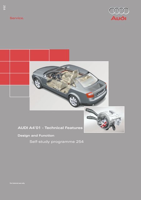
AUDI <strong>A4</strong>´01 - Technical Features<br />
Design and Function<br />
Self-study programme <strong>254</strong>
2<br />
Advance by technology<br />
The new <strong>Audi</strong> <strong>A4</strong>,<br />
a vehicle which combines driving pleasure and good sense<br />
with the highest level of quality and sports styling.<br />
Trapezium link<br />
rear axle...27<br />
Aero-floor<br />
...7<br />
Control unit for vehicle electrical system...48<br />
New engine programme<br />
...18<br />
Electronic stability programme with<br />
brake assistance ...32<br />
Steering column switch module<br />
Crash sensors for front airbag<br />
Multi-communication bar<br />
...72<br />
...44<br />
...14
Contents<br />
Page<br />
Introduction . . . . . . . . . . . . . . . . . . . . . . . . . . . . . . . . . . . . . . . . . . 4<br />
Body . . . . . . . . . . . . . . . . . . . . . . . . . . . . . . . . . . . . . . . . . . . . . . . . 8<br />
Occupant protection . . . . . . . . . . . . . . . . . . . . . . . . . . . . . . . . 12<br />
Engine and gearbox<br />
2.0 l R4 and 3.0 l V6 engines (see SSP 255) . . . . . . . . . . . . . . . . . . . . . . . . . . . . . . . 18<br />
Innovations - 2.5 l V6 TDI engine. . . . . . . . . . . . . . . . . . . . . . . . . . . . . . . . . . . . . . . . 19<br />
Innovations - automatic gearbox . . . . . . . . . . . . . . . . . . . . . . . . . . . . . . . . . . . . . . . 23<br />
Running gear<br />
Axles . . . . . . . . . . . . . . . . . . . . . . . . . . . . . . . . . . . . . . . . . . . . . . . . . . . . . . . . . . . . 26<br />
Mechanical unit mountings . . . . . . . . . . . . . . . . . . . . . . . . . . . . . . . . . . . . . . . . . . . 28<br />
Brake system . . . . . . . . . . . . . . . . . . . . . . . . . . . . . . . . . . . . . . . . . . . . . . . . . . . . . . . 29<br />
Brake assistance . . . . . . . . . . . . . . . . . . . . . . . . . . . . . . . . . . . . . . . . . . . . . . . . . . . . 32<br />
Electrical system<br />
Vehicle electrical system . . . . . . . . . . . . . . . . . . . . . . . . . . . . . . . . . . . . . . . . . . . . . . 36<br />
CAN BUS system . . . . . . . . . . . . . . . . . . . . . . . . . . . . . . . . . . . . . . . . . . . . . . . . . . . . 38<br />
Dash panel insert . . . . . . . . . . . . . . . . . . . . . . . . . . . . . . . . . . . . . . . . . . . . . . . . . . . . 40<br />
Steering column switch module . . . . . . . . . . . . . . . . . . . . . . . . . . . . . . . . . . . . . . ..44<br />
Function circuit diagram . . . . . . . . . . . . . . . . . . . . . . . . . . . . . . . . . . . . . . . 46<br />
Control unit for vehicle electrical system . . . . . . . . . . . . . . . . . . . . . . . . . . . . . . . . 48<br />
Function circuit diagram for "lowline" version. . . . . . . . . . . . . . . . . . . . . 50<br />
Function circuit diagram for "highline" version . . . . . . . . . . . . . . . . . . . . 52<br />
Convenience system . . . . . . . . . . . . . . . . . . . . . . . . . . . . . . . . . . . . . . . . . . . . . . . . . 58<br />
Anti-theft alarm system . . . . . . . . . . . . . . . . . . . . . . . . . . . . . . . . . . . . . . . . . . . . . . . 63<br />
Radio - chorus II, concert II and symphony II . . . . . . . . . . . . . . . . . . . . . . . . . . . . . 65<br />
Navigation IV and Navigation Plus-D . . . . . . . . . . . . . . . . . . . . . . . . . . . . . . . . . . . . 69<br />
Multi-communication bar . . . . . . . . . . . . . . . . . . . . . . . . . . . . . . . . . . . . . . . . . . . . . 72<br />
Electric logbook "<strong>Audi</strong> Logbook" . . . . . . . . . . . . . . . . . . . . . . . . . . . . . . . . . . . . . . . 74<br />
Heater/AC<br />
Design and function . . . . . . . . . . . . . . . . . . . . . . . . . . . . . . . . . . . . . . . . . . . . . . . . . 76<br />
7-piston compressor . . . . . . . . . . . . . . . . . . . . . . . . . . . . . . . . . . . . . . . . . . . . . . . . . 77<br />
Air conditioner . . . . . . . . . . . . . . . . . . . . . . . . . . . . . . . . . . . . . . . . . . . . . . . . . . . . . . 78<br />
Glove compartment cooling . . . . . . . . . . . . . . . . . . . . . . . . . . . . . . . . . . . . . . . . . . . 79<br />
Solar roof. . . . . . . . . . . . . . . . . . . . . . . . . . . . . . . . . . . . . . . . . . . . . . . . . . . . . . . . . . . 80<br />
Fresh air blower . . . . . . . . . . . . . . . . . . . . . . . . . . . . . . . . . . . . . . . . . . . . . . . . . . . . . 81<br />
Actuators/sensors . . . . . . . . . . . . . . . . . . . . . . . . . . . . . . . . . . . . . . . . . . . . . . . . . . . 82<br />
Functional diagram for fully automatic air conditioner . . . . . . . . . . . . . . 84<br />
Additional heater . . . . . . . . . . . . . . . . . . . . . . . . . . . . . . . . . . . . . . . . . . . . . . . . . . . . 86<br />
The self-study programme will provide you with information on<br />
design and functions.<br />
It is not intended as a workshop manual.<br />
For maintenance and repair operations it is essential that you<br />
refer to the current technical literature.<br />
New<br />
Important:<br />
Note<br />
3
4<br />
Introduction<br />
The architecture of motion<br />
Performance and smooth running<br />
The engine programme of the new <strong>Audi</strong> <strong>A4</strong><br />
includes two petrol engines of a completely<br />
new design, with aluminium housings.<br />
The 2.0 litre 4-cylinder in-line engine with<br />
96 kW (130 PS) and the 3.0 litre V6 with<br />
162 kW (220 PS) fulfil the EU 4 emissions<br />
standard.<br />
A high degree of running smoothness is<br />
achieved via balancer shafts.<br />
Infinitely variable perfection<br />
For the first time in this vehicle class, <strong>Audi</strong><br />
offers the infinitely variable "multitronic"<br />
automatic gearbox for all front-wheel drive<br />
versions.<br />
The new light alloy running gear<br />
With the four-link front axle, each wheel is<br />
controlled by four aluminium transverse links.<br />
The pivot bearings are also made from the<br />
same light alloy.<br />
The trapezium link rear axle for the quattro<br />
drive system is also used in the front-wheel<br />
drive models of the <strong>Audi</strong> <strong>A4</strong>.
Finely-tuned aerodynamics<br />
Despite the greater frontal area and the cooling<br />
air current for the air conditioner (standard),<br />
it was possible to improve the CD<br />
value<br />
by 5 %, in comparison to its predecessor,<br />
to 0.28.<br />
A special feature is the so-called aero-floor,<br />
which provides for optimal airflow on the<br />
underside of the vehicle.<br />
SSP<strong>254</strong>_048<br />
Electronic stability programme (ESP)<br />
including brake assistant<br />
For the latest ESP generation, the hydraulic<br />
brake assistant is an integral part of the<br />
standard equipment.<br />
It is intended to assist the driver by automatically<br />
increasing the brake pressure during<br />
emergency braking.<br />
High safety standards<br />
With a thoroughly optimised body design and<br />
comprehensive safety equipment, the new<br />
<strong>Audi</strong> <strong>A4</strong> is able to comply with all current valid<br />
safety standards, throughout the world.<br />
Crash sensors for the front airbags integrated<br />
directly into the bumper bar, improve occupant<br />
protection.<br />
Communication centre on wheels<br />
With regard to infotainment, the new<br />
<strong>Audi</strong> <strong>A4</strong> leaves nothing to be desired.<br />
4 different audio systems, 2 differently configured<br />
Navigation systems and a car phone<br />
with voice operation are on offer.<br />
5
6<br />
Introduction<br />
Vehicle dimensions of <strong>Audi</strong> <strong>A4</strong>´01<br />
1528<br />
1766<br />
1050<br />
1628<br />
977<br />
257<br />
799<br />
870<br />
303<br />
951<br />
1526<br />
445 L<br />
921 2650<br />
976<br />
4527<br />
1400<br />
1357<br />
901<br />
1937<br />
106/110<br />
1000<br />
471<br />
1088<br />
976<br />
SSP<strong>254</strong>_051
The aero-floor<br />
not only contributes to improved aerodynamics.<br />
It was also possible to reduce the noise level<br />
by approx. 3 dB (A).<br />
Front-wheel drive<br />
Four-wheel drive quattro and V6 engine<br />
Part of the additional costs generated by the<br />
aero-floor could be compensated by dispensing<br />
with certain panelling components as<br />
well as by dispensing with PVC protection of<br />
the underside of the vehicle. The latter is of<br />
advantage during recycling.<br />
The aero-floor was designed so as to guarantee<br />
ground clearance and resistance to stone<br />
impact and to prevent accumulation of dirt,<br />
stones and snow.<br />
SSP<strong>254</strong>_053<br />
The engine compartment noise insulation<br />
does not form part of the aerofloor.<br />
7
8<br />
Body<br />
The new <strong>Audi</strong> <strong>A4</strong> is designed for optimal conformance<br />
with current crash requirements<br />
and safety standards.<br />
This could only be achieved by increasing the<br />
body weight.<br />
In order to reduce this additional weight to a<br />
minimum, the proportion of light-weight<br />
materials has been increased in comparison<br />
to its predecessor.<br />
The proportion of high-strength sheet metal<br />
parts as well as the use of a total of 10 large<br />
component "tailored blanks", contribute significantly<br />
to weight reduction.<br />
Body rigidity has been increased by 45 % by<br />
increasing the number of connection points<br />
by 25 %.<br />
Front impact design features<br />
– the straightened longitudinal member with<br />
crash-optimised octagonal cross-piece<br />
– the rigid and significantly wider bumper<br />
cross-piece<br />
– the integration of the member structures<br />
into the passenger cell<br />
– strength, rigidity and weight-optimised<br />
suspension strut cross-piece<br />
SSP<strong>254</strong>_054<br />
Depending upon vehicle weight, performance and fuel consumption are the characteristics<br />
which our customers can experience at first hand.
Side impact design features<br />
In the floor area, the cell consists of three<br />
large tailored blanks, which ensure a stable<br />
connection between the front and rear of the<br />
vehicle.<br />
Weight-saving optimisation of deformation<br />
characteristics in the event of a side impact<br />
was achieved by the use of an aluminium<br />
extruded profile in the sill.<br />
“tailored blanks” are made-to-measure<br />
sheet metal parts with varying material<br />
thickness.<br />
SSP<strong>254</strong>_055<br />
SSP<strong>254</strong>_056<br />
9
10<br />
Body<br />
Doors<br />
The doors of the <strong>Audi</strong> <strong>A4</strong> demonstrate a significantly<br />
increased rigidity due to the onepiece<br />
door shell construction.<br />
For the first time, a so-called spray-on noise<br />
insulation is used, which is sprayed on as<br />
required and allows weight reduction for the<br />
same effectiveness.<br />
SSP<strong>254</strong>_066<br />
Noise insulation<br />
In addition, the doors have been fitted with a<br />
second weatherseal. One weatherseal is fitted<br />
to the door and the other is fitted to the body.<br />
The new door concept permits a reduction in<br />
the overall noise level of a further 3 dB (A) and<br />
thus contributes to improving the aero-acoustics.<br />
Door trim<br />
SSP<strong>254</strong>_067<br />
The newly developed sub-frame is bolted to<br />
the door shell via fitted bolts.<br />
Door seal<br />
Door frame<br />
Roof<br />
Door frame seal<br />
Roof trim strip<br />
Door window<br />
seal<br />
Door window<br />
SSP<strong>254</strong>_075
Emergency door locking<br />
In the event of failure of the central locking,<br />
e.g. due to power supply faults, each door can<br />
be individually locked without using the lock<br />
cylinder.<br />
Firstly, with the door open, the cap must be<br />
removed. Emergency locking is effected by<br />
inserting the ignition key.<br />
After the door has been closed, it is not possible<br />
to open it from the outside.<br />
The door can be opened from the inside by<br />
actuating the door release handle twice.<br />
Luggage compartment lid<br />
The luggage compartment lid should always<br />
be operated via the radio remote control.<br />
The lock cylinder for the luggage compartment<br />
lid is integrated into the handle.<br />
Continuous locking of luggage compartment<br />
If the lock cylinder is in the horizontal position<br />
with the key removed, the luggage compartment<br />
lid is no longer included in the<br />
central locking system. Opening is then only<br />
possible via the centre unlocking button of<br />
the radio remote control.<br />
When the lock cylinder is in the vertical position,<br />
the lid is an integral part of the central<br />
locking system.<br />
Manual unlocking and opening<br />
is effected by turning the key to the left.<br />
In this position, it is not possible to remove<br />
the key, which must subsequently be returned<br />
to the vertical position.<br />
Thus, it is ensured that the luggage compartment<br />
lid is an integral part of the central locking<br />
system.<br />
SSP<strong>254</strong>_069<br />
SSP<strong>254</strong>_070<br />
SSP<strong>254</strong>_071<br />
SSP<strong>254</strong>_072<br />
11
12<br />
Occupant protection<br />
Overview of system<br />
N277<br />
G 256<br />
G179<br />
J285/K75<br />
N199<br />
N153<br />
N201<br />
J533<br />
T16<br />
G 283 G 284<br />
J162<br />
N95<br />
J220<br />
J393 J234<br />
J526<br />
K145<br />
AIRBAG<br />
OFF<br />
N131<br />
AIRBAG<br />
AUS EIN<br />
E224<br />
N200<br />
N154<br />
N202<br />
G180<br />
N278<br />
G 257<br />
SSP<strong>254</strong>_029
To complement the comprehensive body<br />
modifications, occupant protection has been<br />
improved through the further development of<br />
the familiar 8.4 airbag system.<br />
The new generation bears the designation<br />
8.4 E, where the E stands for<br />
"extended".<br />
The position of the sensors is selected so that<br />
they are installed as near as possible to the<br />
outer structure of the vehicle.<br />
This enables quicker deceleration detection in<br />
the event of an impact.<br />
Key<br />
E224 Key switch for switching off<br />
passenger’s side airbag<br />
G179 Side airbag crash sensor, driver’s<br />
side (B-pillar)<br />
G180 Side airbag crash sensor, passenger’s<br />
side (B-pillar)<br />
G256 Crash sensor for rear side airbag,<br />
driver’s side<br />
G257 Crash sensor for rear side airbag,<br />
passenger's side<br />
G283 Front airbag crash sensor, driver’s<br />
side<br />
G284 Front airbag crash sensor,<br />
passenger’s side<br />
J162 Heater control unit<br />
J220 Control unit for motronic<br />
J234 Airbag control unit<br />
J285 Control unit with display unit in<br />
dash panel insert<br />
J393 Central control unit for convenience<br />
system<br />
J526 Control unit for telephone /<br />
telematics<br />
J533 Diagnosis interface for data bus<br />
(Gateway)<br />
The system comprises driver/passenger airbags,<br />
front side airbags, optional rear side<br />
airbags, SIDEGUARDS®<br />
, three point front seat<br />
belts with ball tensioners and belt force limiters,<br />
three point rear outer seat belts, centre<br />
lap belt (for fixed rear seat bench), Isofix preparation<br />
in rear of vehicle, and a total of 6<br />
non-central accelerometers:<br />
– 2 front impact crash sensors<br />
– 2 driver/passenger side airbag crash sensors,<br />
(in the B-pillar for side impact)<br />
– 2 driver/passenger rear side airbag crash<br />
sensors, (on the C-pillar for side impact)<br />
The external sensors deliver digitised acceleration<br />
data to the airbag control unit, which is<br />
then evaluated in the control unit and which<br />
triggers the relevant restraint system components.<br />
K75 Airbag warning lamp<br />
K145 "Airbag off" warning lamp,<br />
passenger's side<br />
N95 Airbag igniter, driver's side<br />
N131 Airbag igniter 1, passenger's side<br />
N153 Igniter for belt tensioner, driver's side<br />
N154 Igniter for belt tensioner,<br />
passenger's side<br />
N199 Igniter for side airbag, driver’s side<br />
N200 Igniter for side airbag, passenger's<br />
side<br />
N201 Igniter for rear side airbag,<br />
driver’s side<br />
N202 Igniter for rear side airbag,<br />
passenger's side<br />
N277 Igniter for airbag in B-pillar<br />
(SIDEGUARD®<br />
), driver's side<br />
N278 Igniter for airbag in B-pillar<br />
(SIDEGUARD<br />
®<br />
), passenger's side<br />
T16 Connector, 16-pin, diagnosis<br />
connection<br />
13
14<br />
Occupant protection<br />
Crash sensors for front airbag G283, 284<br />
Both sensors for front impact detection function<br />
in conjunction with the crash sensor and<br />
the safe sensor which are integrated into the<br />
airbag control unit J234.<br />
Deceleration load<br />
Upper body<br />
Head<br />
Impact<br />
Triggering of belt tensioners<br />
Triggering of front airbags<br />
Front airbags inflated<br />
Belt force limiter<br />
response<br />
Damping function<br />
response in<br />
the steering column<br />
Time [ms]<br />
If a certain signal threshold is exceeded in the<br />
front airbag crash sensor, a threshold reduction<br />
is activated in the airbag control unit,<br />
which results in a shorter triggering time.<br />
SSP<strong>254</strong>_058<br />
Vehicle rebound<br />
SSP<strong>254</strong>_063<br />
SSP<strong>254</strong>_064
Crash sensors for side airbags<br />
G179, 180, 256, 257<br />
In order to trigger the components of the<br />
restraint system, two simultaneous impact<br />
detection signals are required for the plausibility<br />
check:<br />
– from both opposing crash sensors<br />
(B-pillar left with right and/or<br />
(C-pillar left with right) and<br />
– from the control unit internal crash sensors.<br />
The crash sensors are designed in such a way<br />
that incorrect installation is excluded.<br />
Airbag control unit J234<br />
The warning lamp for airbag K75 is activated<br />
continuously following a detected impact.<br />
"CRASH DATA STORED" and the triggered<br />
components are displayed with fault code<br />
during fault memory readout.<br />
Sensors and components to be replaced<br />
following an accident, are listed in the<br />
current workshop manual.<br />
SSP<strong>254</strong>_059<br />
Re-encoding of the airbag control unit is no<br />
longer possible after the first crash data message<br />
is stored.<br />
Triggering is performed in two thresholds<br />
depending upon the deceleration value:<br />
– Threshold 1 = belt tensioners only<br />
– Threshold 2 = belt tensioners and airbag(s)<br />
15
16<br />
Occupant protection<br />
Deactivation of passenger airbag<br />
Deactivation of the passenger airbag is only<br />
possible via the key switch. In the <strong>Audi</strong> <strong>A4</strong>, the<br />
passenger's side airbag is also deactivated.<br />
Deactivation via the diagnostic tester is not<br />
possible.<br />
If a customer requires the deactivation function<br />
where a key switch is not fitted, this can<br />
only be achieved by retrofitting the key switch<br />
and airbag OFF lamp and by re-encoding of<br />
the airbag control unit.<br />
Front belt attachment<br />
�� ��<br />
Belt lock and strap fastenings are permanently<br />
connected to the seat frame. Thus, in<br />
conjunction with the seat belt height adjuster,<br />
an optimal belt fitting can be achieved for<br />
each seat position.<br />
Front head restraints<br />
In order to offer a high degree of occupant<br />
protection in conjunction with the seat belt<br />
and airbag, the front head restraints have<br />
been supplemented by an integral locking<br />
mechanism.<br />
��<br />
SSP<strong>254</strong>_101<br />
SSP<strong>254</strong>_102<br />
SSP<strong>254</strong>_011
Crash signal processing<br />
There are two separate crash signal outputs:<br />
One crash signal is output via the conventional<br />
wiring and triggers the following functions:<br />
– Transmitting an emergency call via the<br />
control unit for telephone/telematics J526<br />
(optional)<br />
– unlocking the vehicle,<br />
– Switch on interior light<br />
(switch must be set to door contact),<br />
– switching on hazard warning lights via the<br />
central convenience electronics J393.<br />
The auxiliary heater J162 (optional) is<br />
switched off by the central convenience<br />
electronics J393 via a CAN convenience<br />
message.<br />
The second crash signal output functions via<br />
the convenience CAN bus, which switches off<br />
the engine fuel supply via the engine control<br />
unit J220.<br />
17
18<br />
Engine and gearbox<br />
Engine<br />
The 4-cylinder, 2.0 l engine<br />
provides high propulsive force due to the<br />
maximum torque of 195 Nm at 3300 rpm.<br />
The 3,0 l V6 engine<br />
SSP<strong>254</strong>_038<br />
with five-valve cylinder head, produces162 kW<br />
(220 PS) at 6300 rpm from 2976 cm3.<br />
The maximum torque of 300 Nm is developed<br />
at 3200 rpm.<br />
SSP<strong>254</strong>_030<br />
Torque [Nm]<br />
Torque [Nm]<br />
Engine speed in rpm<br />
Engine speed in rpm<br />
Power output [kW]<br />
SSP<strong>254</strong>_060<br />
Power output [kW]<br />
SSP<strong>254</strong>_061<br />
Detailed information on these engines<br />
can be found in SSP 255.
Innovations 2.5 l V6 TDI engine<br />
Technical data<br />
Capacity: 2496 cm3<br />
Bore: 78.3 mm<br />
Stroke: 86.4 mm<br />
Compression: 18.5 : 1<br />
The main features of the basic engine are the<br />
same as those of the familiar V6 TDI engine<br />
with 132 kW (180 PS).<br />
Power output and torque curve values could<br />
be maintained under conditions which were<br />
well within EU 3 limit values.<br />
Limit value [%]<br />
SSP255_045<br />
Power output: 132 kW (180 PS)<br />
Torque: 370 Nm at 1500 rpm<br />
NOx HC+NOx CO Particle<br />
Torque [Nm]<br />
The injection system was modified in order to<br />
reduce exhaust gas and particle emissions.<br />
SSP255_038<br />
Engine speed in rpm<br />
EU 3 limit values 100 %<br />
Particle = 0.05 g/km<br />
CO = 0.64 g/km<br />
HC+NOx = 0.56 g/km<br />
NOx = 0.50 g/km<br />
Power output [kW]<br />
SSP255_039<br />
Injection system: Bosch VE VP 44 S3.5<br />
Turbocharger: VNT 20<br />
Exhaust emissions class: EU 3<br />
Consumption: urban 11.0 l/100 km<br />
(6-gear, quattro) country 6.1 l/100 km<br />
average 7.8 l/100 km<br />
19
20<br />
Engine and gearbox<br />
Injection pump VP 44 S3.5<br />
Distributor bushing<br />
Distributor shaft<br />
Supply piston<br />
Thermal shoulder<br />
The high pressure section of the injection<br />
pump has been redesigned with regard to<br />
pressure levels and quicker solenoid valve<br />
actuation.<br />
The injection pressure at part throttle has<br />
been increased by the following measures:<br />
Forced flush feed<br />
– increased cam stroke from 3.5 to 4.0 mm<br />
– more stable support structure for high<br />
pressure section on pump body<br />
– conversion from 3 pistons with a diameter<br />
of 6.0 mm, to 2 pistons with a diameter of<br />
7.0 mm.<br />
By reducing the number of high-pressure pistons<br />
from 3 to 2, it was possible to reduce<br />
high-pressure leakage via the sealing surfaces.<br />
Forced flush<br />
return<br />
SSP255_040<br />
Solenoid valve<br />
In order to initiate pre-injection for cold and<br />
warm engines, the solenoid valve dynamics<br />
have been significantly increased.<br />
The associated increased heat generation in<br />
the solenoid valve, is compensated by<br />
improved fuel flow and optimal filling of the<br />
high pressure section is achieved.<br />
Noise levels have been significantly improved<br />
by the pre-injection for cold and warm operation<br />
and the use of dual-spring nozzle holders.<br />
Previously, pre-injection via the solenoid<br />
valve was only realised during the engine<br />
warm-up phase.
Injector<br />
For the first time, an ICU injector ( Inverse<br />
Cav<br />
ity Undercut)<br />
is used, which has a dual needle<br />
guide.<br />
The advantage of this ICU geometry is a significantly<br />
improved spray formation, especially<br />
in the part throttle range for small<br />
injection quantities and short needle lift.<br />
Dual needle guide<br />
Due to the improved spray formation through<br />
the use of the ICU injector, it was possible to<br />
reduce the exhaust emissions and the particle<br />
values by up to 20 %.<br />
ICU seat geometry<br />
SSP255_041<br />
ICU seat geometry Standard seat geometry<br />
SSP255_042<br />
21
22<br />
Engine and gearbox<br />
Charge air cooler<br />
The existing series connection of the two<br />
charge air coolers for the 110 kW engine is<br />
inadequate for the 132 kW engine with its<br />
high air throughput.<br />
A new charge air cooler design was developed,<br />
in order to ensure optimal charge air<br />
flow.<br />
Through duct<br />
Cooling duct section<br />
SSP255_043<br />
The charge air cooler design comprises two<br />
sections, in which part of the charge air is fed<br />
via a through duct, connected to a space-saving<br />
pipe, to the section of the other charge air<br />
cooler which is fitted with cooling fins.<br />
The rest of the charge air is fed directly<br />
through the cooling fins, via a separate pipe,<br />
to the second charge air cooler and into the<br />
through duct.
Innovations - automatic<br />
gearbox<br />
5-speed 01V automatic gearbox<br />
The <strong>Audi</strong> <strong>A4</strong> quattro MJ01 with 5-speed automatic<br />
gearbox features a new shift lever gate,<br />
together with a new shifting concept.<br />
The existing selector lever positions, 4,3,2 are<br />
discontinued and are replaced by the "S"<br />
position.<br />
Gearshift positions 4,3,2 have been discontinued<br />
as they are hardly ever used in practice.<br />
The DSP (dynamic shift programme) and "tiptronic"<br />
function have basically rendered them<br />
superfluous.<br />
With the selector lever is in the "S" position, a<br />
sports shift programme provides the relevant<br />
driving dynamics. In position "S", the DSP<br />
also provides for adaptation of the driving set<br />
values to the driving conditions.<br />
The introduction of the "S" programme enables<br />
a significant extension of the useful shift<br />
range between economy and sports.<br />
The "S" programme comprises the following<br />
special features:<br />
– If, during driving with constant accelerator<br />
pedal position, the selector lever is set to<br />
the "S" position, the system always shifts<br />
down, within defined limits.<br />
– In order to achieve a direct driving reaction<br />
in response to accelerator pedal actuation,<br />
the converter clutch is closed during driving<br />
operation, where possible.<br />
– If, in conjunction with the overall gearbox<br />
ratio, 5th gear is designed as overdrive<br />
gear (overdrive, 4+E), only 1st -4th gears<br />
are shifted.<br />
We recommend the multi-function steering<br />
wheel (available as optional extra) with steering<br />
wheel "tiptronic" ("thumb shifting").<br />
Throttle valve angle [%]<br />
P<br />
R +<br />
N<br />
D<br />
S<br />
Example: Dynamics code 40<br />
Shift map 1<br />
Gearbox output speed [rpm]<br />
D - normal driving programme<br />
S - sports driving programme<br />
SSP<strong>254</strong>_117<br />
SSP<strong>254</strong>_103<br />
23
24<br />
Engine and gearbox<br />
"multitronic" and 5-speed automatic gearbox<br />
An innovation for all automatic gearboxes is<br />
the "Tip in D " function. This means that the<br />
steering wheel "tiptronic" function is now<br />
also available in selector lever position "D".<br />
The transition to the "tiptronic" function is<br />
effected by actuating one of the two tip<br />
switches on the multi-function steering wheel<br />
(selector lever in position "D"). The system<br />
then switches to the "tiptronic" function for<br />
approx. 10 seconds. All gears can be shifted<br />
within the range of permissible engine<br />
speeds.<br />
The system returns to normal automatic operation<br />
approx. 10 seconds after the last tip<br />
request.<br />
Special feature:<br />
SSP<strong>254</strong>_088<br />
The countdown from approx. 10 seconds to<br />
return to normal automatic operation is interrupted,<br />
in the event that cornering is detected<br />
or the vehicle is in overrun operation.<br />
When normal driving conditions are detected<br />
again, the countdown recommences from<br />
approx. 10 seconds.
Notes<br />
25
26<br />
Running gear<br />
Axles<br />
Four-link front axle<br />
The thorough further development of the<br />
light-weight construction resulted in a weight<br />
reduction of approx. 8.5 kg at the front axle.<br />
In addition to all transverse links, the pivot<br />
bearing is now also made of aluminium.<br />
The wheel bearing is attached to the pivot<br />
bearing via four bolts. The wheel hub can be<br />
pressed in and out.<br />
Aluminium<br />
spring plate<br />
SSP<strong>254</strong>_086<br />
Aluminium mounting bracket<br />
The suspension strut mounting is of the bulky<br />
rubber bearing construction.<br />
It consists of two functional components:<br />
– The inner part forms the connection to the<br />
piston rod.<br />
– The larger outer part provides for acoustic<br />
insulation of the shock absorber.<br />
Shock absorber valves<br />
SSP<strong>254</strong>_087<br />
Aluminium pivot bearing<br />
SSP<strong>254</strong>_085
Trapezium link rear axle<br />
The rear axle design with largely identical<br />
components is used in both the front-wheel<br />
drive as well as in the quattro versions.<br />
Toe adjustment<br />
The front-wheel drive version is fitted with a<br />
wheel bearing unit with integral wheel hub,<br />
which is mounted on a stub axle forged<br />
together with the wheel carrier.<br />
Toe adjustment<br />
SSP<strong>254</strong>_089<br />
The wheel bearings of the quattro version<br />
consist of pressed-in, double-row angular ball<br />
bearings with conventional wheel hubs.<br />
Camber<br />
adjustment<br />
SSP<strong>254</strong>_091<br />
Apart from the axle mounting, the two axle<br />
versions differ only in the wheel carrier and<br />
the wheel bearings.<br />
Camber<br />
adjustment<br />
SSP<strong>254</strong>_083<br />
SSP<strong>254</strong>_082<br />
27
28<br />
Running gear<br />
Mechanical unit mountings<br />
Torque<br />
member<br />
A newly designed three-point mechanical unit<br />
mounting is used in the new <strong>Audi</strong> <strong>A4</strong>.<br />
The hydraulically damped engine mountings<br />
(electrically-controlled version for diesel<br />
engines) are fastened directly to the longitudinal<br />
members via die-cast aluminium brackets.<br />
The gearbox mounting is effected by means<br />
of a conventional rubber bearing on a bodymounted<br />
aluminium carrier, which is produced<br />
according to the hollow sand casting<br />
technique.<br />
Engine mounting 1<br />
Engine<br />
mounting 2<br />
Cross member<br />
Gearbox<br />
mounting 3<br />
SSP<strong>254</strong>_107<br />
The additional cross member enables support<br />
over a longer lever arm, which positively influences<br />
vibration and load cycle characteristics.<br />
The aluminium cross member is bolted to the<br />
body as well as to the rear subframe mountings<br />
and, in addition to its supporting function<br />
for the gearbox mounting, serves as a<br />
body-stiffening tunnel bridge.<br />
The three-point mechanical unit mounting<br />
is used for all engine/gearbox<br />
combinations except those including<br />
the 01V 5-speed automatic gearbox.
Brake system<br />
The new Bosch ESP 5.7 is introduced in the<br />
<strong>Audi</strong> <strong>A4</strong>. The ESP 5.7 is distinguished by the<br />
following special features:<br />
– The hydraulic unit and control unit form a<br />
single unit.<br />
– The charging pump (actuation of ESP<br />
hydraulic pump V156) is discontinued.<br />
– A brake assistant is included.<br />
Hydraulic modulator<br />
Due to the increased brake fluid viscosity at<br />
extremely low ambient temperatures, the<br />
required delivery rate for the return pump for<br />
ABS V39 could not be achieved without a<br />
charging pump (resulting from the increased<br />
suction resistance in the system).<br />
The purpose of the development of the<br />
ESP 5.7 was to improve the suction of the ABS<br />
return pump so that the charging pump was<br />
no longer necessary.<br />
The charging pump could be discontinued<br />
through the use of a two-stage ABS return<br />
pump, enlarging the cross-section of the<br />
brake lines and the use of a larger-dimensioned<br />
central valve in the brake master cylinder.<br />
SSP<strong>254</strong>_094<br />
29
30<br />
Running gear<br />
Single-stage ABS return pump<br />
The graphic shows a comparison of the<br />
suction volumes of both pump versions.<br />
In the single-stage ABS return pump, the<br />
entire suction volume must be drawn in and<br />
flow through the suction line during one<br />
piston stroke (piston stroke from TDC to BDC).<br />
Suction volumes<br />
UT OT UT<br />
OT UT<br />
Suction volumes<br />
UT OT UT<br />
OT UT<br />
SSP<strong>254</strong>_095<br />
The suction pressure is correspondingly high<br />
and increases with increasing viscosity.<br />
Cavitation and the associated drop in<br />
performance on the pressure side, are the<br />
results.
Two-stage ABS return pump<br />
Working chamber 1<br />
The piston of the two-stage ABS return pump<br />
is stepped and has a double-acting function<br />
within two working chambers.<br />
Suction is effected in two stages; brake fluid<br />
being drawn through the suction line during<br />
each piston stroke.<br />
Function:<br />
Working chamber 2<br />
If the piston moves from BDC to TDC, the<br />
brake fluid in working chamber 1 is compressed<br />
whereas working chamber 2 is simultaneously<br />
under suction.<br />
If the piston then moves from<br />
TDC to BDC, the brake fluid which has been<br />
drawn into working chamber 2 is forced back<br />
into the suction line against the inlet valve.<br />
Suction volumes<br />
UT OT UT<br />
OT<br />
UT OT UT<br />
OT<br />
SSP<strong>254</strong>_096<br />
As the entire suction volume is supplied<br />
almost continuously, the maximum suction<br />
flow rate is significantly lower, which diminishes<br />
the suction pressure and prevents<br />
cavitation.<br />
Thus, a quick pressure build-up is ensured,<br />
even at extremely low temperatures.<br />
In working chamber 1, brake fluid is now<br />
drawn via the open inlet valve, out of the suction<br />
line and out of the connection line to<br />
working chamber 2.<br />
The suction flow rate in the suction line is<br />
diminished by that amount which flows back<br />
out of the connection line from working<br />
chamber 2<br />
(drawn in during previous working operation).<br />
31
32<br />
Running gear<br />
Brake assistant<br />
Investigations in accident research have<br />
shown, that the majority of drivers fail to adequately<br />
actuate the brakes in an emergency<br />
situation.<br />
This results in insufficient brake pressure<br />
being generated to achieve maximum vehicle<br />
deceleration.<br />
This lengthens the braking distance.<br />
Brake servo pressure sensor G294 is used for<br />
detection of emergency braking.<br />
Pressure sensor G294<br />
For this purpose, the pressure increase gradient<br />
(pressure build-up with respect to time) is<br />
evaluated and, if necessary, the brake assistant<br />
is activated.<br />
During emergency braking, the brake assistant<br />
aids the driver by increasing the brake<br />
pressure automatically, to a level exceeding<br />
the locking limit.<br />
The ABS ( Anti-lockbrakingsystem)<br />
is thus<br />
quickly brought into the operating range,<br />
which enables a maximum vehicle deceleration<br />
to be achieved.<br />
Pressure [p]<br />
Time [t]<br />
Emergency braking<br />
Normal braking distance<br />
SSP<strong>254</strong>_093<br />
SSP<strong>254</strong>_092
The function of the brake assistant is<br />
sub-divided into 2 phases:<br />
• Phase 1<br />
If the pressure increase gradient exceeds a<br />
specified value (emergency braking), the ABS<br />
return pump and the relevant solenoid valve<br />
are activated by the ESP control unit and the<br />
brake pressure is thus increased into the ABS<br />
control range, in a similar manner to that of<br />
the control system for an electronic differential<br />
lock.<br />
Brake pressure [p]<br />
• Phase 2<br />
If the pressure determined by the driver falls<br />
below a certain value after triggering of the<br />
brake assistant, the system pressure is<br />
restored to the pedal pressure determined by<br />
the driver.<br />
Brake assistant activated Brake pedal unloaded Brake assistant<br />
switches off<br />
Phase 1 Phase 2<br />
Time [t]<br />
Brake pressure determined by an<br />
experienced driver<br />
Regulated brake pressure<br />
(brake assistant)<br />
Determined brake pressure<br />
insufficient inexperienced driver<br />
SSP<strong>254</strong>_084<br />
ABS control<br />
range<br />
The integral inlet and outlet valves in the<br />
hydraulic modulator are no longer simply<br />
switched on/off, but are regulated<br />
via supplied voltage.<br />
This enables more precise control on<br />
extremely slippery surfaces, e.g. ice.<br />
33
34<br />
Running gear<br />
Brake fluid reservoir<br />
The brake fluid reservoir is secured with an<br />
additional screw.<br />
The new maintenance opening in the brake<br />
fluid reservoir enables the extraction of brake<br />
fluid from both brake fluid chambers.<br />
The new brake filler and bleeder unit<br />
VAS 5234 must be used for this purpose.<br />
Brake light switch<br />
The fastening and adjustment of the brake<br />
light switch are new.<br />
The brake light switch is secured to the pedal<br />
bracket via a bayonet fitting.<br />
The position of the push rod is adjusted for<br />
the basic setting.<br />
For this purpose, the brake light switch must<br />
be released by turning it anti-clockwise.<br />
The push rod catch is released simultaneously<br />
via the locking lug.<br />
The push rod is now free and can be adjusted<br />
without risk of damage.<br />
The push rod is pulled out to the stop for the<br />
basic setting.<br />
The brake light switch can now be inserted<br />
into the pedal bracket and secured by turning<br />
clockwise. At the same time, the push rod<br />
catch is locked automatically by means of the<br />
locking lug.<br />
Maintenance opening<br />
Fastening screw<br />
SSP<strong>254</strong>_098<br />
SSP<strong>254</strong>_099
Notes<br />
35
36<br />
Electrical system<br />
Vehicle electrical system<br />
Control unit for<br />
coolant fan,<br />
Stage 1+2 J293<br />
Control unit for<br />
telematics J499<br />
Control unit for<br />
mobile phone control<br />
electronics J412<br />
Control unit with<br />
display in dash panel<br />
insert J285<br />
Battery<br />
Front airbag crash<br />
sensor, passenger’s<br />
side G284<br />
Front airbag crash sensor,<br />
driver’s side G283<br />
Control unit<br />
for ESP J104<br />
Control unit for headlamp<br />
range control J431<br />
Control unit<br />
for Motronic J220<br />
Control unit for automatic<br />
gearbox J217<br />
Chip card<br />
reader R99<br />
Steering column<br />
switch module J527
Side airbag crash sensor,<br />
passenger’s side G180<br />
Control unit for vehicle electrical<br />
system J519<br />
ESP sensor<br />
Door control units,<br />
passenger side J387<br />
rear right,<br />
optional J389<br />
Side airbag crash sensor, rear<br />
driver’s side G256<br />
passenger’s side G257<br />
Airbag control<br />
unit J234<br />
Side airbag crash sensor,<br />
driver’s side G179<br />
Control unit for trailer<br />
recognition J345<br />
Door control unit,<br />
driver’s side J386,<br />
rear left, optional J388<br />
Control unit for<br />
parking aid J446<br />
Control unit for<br />
tyre pressure<br />
monitor J502<br />
Central control unit for<br />
convenience system J393<br />
SSP<strong>254</strong>_008<br />
37
38<br />
Electrical system<br />
CAN BUS networking<br />
Diagnosis system<br />
J220<br />
J217<br />
NOX sensor<br />
(USA only)<br />
J527<br />
G85<br />
J104<br />
J234<br />
J285<br />
J519<br />
J386<br />
J388<br />
J393<br />
E87<br />
J345<br />
The ignition switch signals and the<br />
control buttons for multifunction<br />
and "tiptronic" steering wheel are<br />
registered via the steering column<br />
electronics.<br />
J527<br />
Gateway<br />
R<br />
T<br />
J387<br />
J389<br />
+<br />
-<br />
J502<br />
J162<br />
J446<br />
J136<br />
J453<br />
TRACK<br />
SEEK<br />
J526<br />
J401<br />
J507<br />
R99<br />
J499<br />
EJECT<br />
FR FF<br />
TUNE SCAN<br />
CD CDC<br />
1 2 3 4 5 6<br />
AS<br />
1 AM 2<br />
TP<br />
DOLBY SYSTEM<br />
EJECT <strong>Audi</strong> symphony<br />
1 FM 2 BASS MIDDLE TREBLE BALANCE FADER<br />
RDS<br />
PLAY SDE<br />
TAPE<br />
RANDOM<br />
R<br />
J402<br />
R94
CAN data bus<br />
The <strong>Audi</strong> <strong>A4</strong> is equipped with a widely<br />
extended CAN data bus system.<br />
Due to the ever increasing number of control<br />
units installed in the vehicle and the associated<br />
requirement for data exchange, the<br />
importance of the CAN data bus system<br />
increases significantly.<br />
G85 Steering angle sender<br />
E87 Operating and display unit for<br />
air conditioner<br />
J104 Control unit for ESP<br />
J136 Control unit for seat adjustment with<br />
memory, optional<br />
J162 Auxiliary heater, optional<br />
J217 Control unit for automatic gearbox<br />
J220 Control unit for motronic<br />
J234 Airbag control unit<br />
J285 Control unit with display unit in<br />
dash panel insert<br />
J345 Control unit for trailer recognition<br />
J386 Door control unit, driver’s side<br />
J387 Door control unit, passenger side<br />
J388 Rear left door control unit, optional<br />
J389 Rear right door control unit, optional<br />
J393 Central control unit for convenience<br />
system<br />
J401 Navigation system control unit<br />
The newly developed adapter VAS 6017 enables<br />
communication with all control units.<br />
For communication between the<br />
installed control units and the diagnostic<br />
tester, two diagnosis wires (K and L)<br />
are available.<br />
J402 Control unit for operating electronics,<br />
navigation, TV tuner<br />
J446 Control unit for parking aid<br />
J453 Control unit for multi-function<br />
steering wheel<br />
J499 Control unit for telematics<br />
J502 Control unit for tyre pressure monitor<br />
J507 Control unit for speech entry<br />
J519 Control unit for vehicle electrical<br />
system<br />
J526 Control unit for telephone -<br />
permanent installation<br />
J527 Control unit for steering column<br />
electronics<br />
R Radio<br />
R94 Interface for navigation<br />
R99 Chip card reader<br />
Drive BUS 500 kBaud<br />
Convenience BUS 100 kBaud<br />
Display BUS 100 kBaud<br />
Diagnosis connection<br />
K wire<br />
Diagnosis connection<br />
L wire (2nd K wire)<br />
SSP<strong>254</strong>_112<br />
39
40<br />
Electrical system<br />
Dash panel insert<br />
Setting buttons for digital clock,<br />
date and instrument illumination<br />
There are two dash panel insert versions:<br />
– "lowline"<br />
– "highline"<br />
The "highline" version is equipped with a<br />
high-quality colour display for the driver information<br />
system and is installed in vehicles<br />
with navigation systems as well as telematics.<br />
Cruise control system ON<br />
Auto-check system<br />
Call-up button for<br />
service interval<br />
indicator<br />
SSP<strong>254</strong>_012<br />
Reset button for trip<br />
recorder<br />
The dash panel insert of the new <strong>Audi</strong> <strong>A4</strong> is<br />
equipped with<br />
– the gateway for linking the three data bus<br />
systems: drive, convenience, information<br />
– and the immobiliser III.
User prompt in the centre display via the control<br />
switch in the centre console, is only available<br />
in vehicles with<br />
– navigation system ("highline" version only)<br />
and/or<br />
– telematics and/or<br />
– auxiliary heater and/or<br />
– tyre pressure monitoring.<br />
The optional driver information system<br />
includes the following functions:<br />
– radio clock<br />
– auto-check system<br />
– on-board computer.<br />
The km range is indicated in the basic version.<br />
In order to ensure good signal reception for<br />
the radio clock, the receiver is installed in the<br />
rear bumper bar.<br />
+ 5 V<br />
Earth<br />
Radio signal<br />
SSP<strong>254</strong>_104<br />
SSP<strong>254</strong>_108<br />
41
42<br />
Electrical system<br />
A new feature of the Auto-Check system<br />
is the position-dependent bulb monitor display.<br />
The fault message is transmitted from the vehicle<br />
electrical system control unit J519, via the<br />
convenience data bus, to the dash panel insert<br />
J285 and appears on the centre display.<br />
Convenience data<br />
bus<br />
The <strong>Audi</strong> <strong>A4</strong> quattro is equipped with two fuel<br />
gauge senders G and G169.<br />
Sender G registers the lower, and sender<br />
G169 the upper partial volume in the fuel<br />
tank.<br />
The signals from senders G and G169 are<br />
evaluated separately. The calculated litre<br />
values are then added and displayed.<br />
Control unit with<br />
display unit in dash<br />
panel processor J285<br />
Control unit for vehicle<br />
electrical system J519<br />
SSP<strong>254</strong>_125<br />
Fuel gauge<br />
sender G<br />
SSP<strong>254</strong>_118<br />
Fuel gauge<br />
sender 2, G169<br />
SSP<strong>254</strong>_123
Diagnostics<br />
Convenience data<br />
bus<br />
Control unit for steering<br />
column electronics J527<br />
Ignition lock D<br />
The dash panel insert checks the plausibility<br />
– of both fuel gauge senders in quattro<br />
vehicles<br />
– as well as the terminal 15 input signal.<br />
Due to the gateway function of the dash panel<br />
insert, the communication with the individual<br />
control units connected to the CAN data bus<br />
is checked during diagnosis.<br />
Communication faults are entered into the<br />
fault memory. The current status can be read<br />
in the measured value blocks.<br />
Terminal 15<br />
Control unit with<br />
display unit in<br />
dash panel insert J285<br />
SSP<strong>254</strong>_138<br />
A further innovation is the display of the maximum<br />
and minimum engine oil levels in the<br />
measured value block after the most recent<br />
service operation.<br />
The adaptation of the mileage/kilometre reading<br />
after replacement of the dash panel<br />
insert, is possible (several attempts) up to a<br />
recorded distance of 5 km after installation.<br />
43
44<br />
Electrical system<br />
Steering column switch<br />
module<br />
Due to the compact design of the newly<br />
developed steering column switch module, it<br />
was possible to minimise the amount of wiring<br />
necessary and the space requirements.<br />
A self-diagnosis facility for the steering column<br />
switch is now available with new switch<br />
module.<br />
The steering column switch module consists<br />
of the following components:<br />
– Turn signal switch<br />
– Wiper switch with interval potentiometer<br />
– Separate steering column switch cruise<br />
control system operation<br />
– Coil spring for diver's airbag<br />
– Steering angle sensor for ESP<br />
– Steering column electronics for signal conversion<br />
and processing of drive and convenience<br />
CAN BUS J527<br />
In addition, the steering column electronics<br />
register the ignition switch signals.<br />
Furthermore, the control buttons for multifunction<br />
and "tiptronic" steering wheel are<br />
registered via the steering wheel electronics<br />
module.<br />
Steering column switch<br />
Detection of the respective switch positions is<br />
effected via voltage coding, using various<br />
resistance values in the relevant position. The<br />
steering column electronics evaluates this<br />
switch information and transmits it, via the<br />
convenience CAN BUS, to the vehicle electrical<br />
system control unit J519.<br />
Cruise control system (CCS)<br />
For ergonomic reasons, the control switch for<br />
the cruise control system is located on the<br />
left side of the steering column, below the<br />
turn signal lever.<br />
Warning lamp K31 in the dash panel insert<br />
illuminates when the CCS is in control mode.<br />
The modified operation of the CCS Steering<br />
column switch function is described in the<br />
Owner's Manual.<br />
Steering column<br />
electronics J527<br />
Turn signal<br />
switch E2<br />
Ignition<br />
steering lock<br />
Cruise control<br />
system E45<br />
SSP<strong>254</strong>_105
Wiper<br />
switch E<br />
Steering column electronics<br />
module J453 with operating<br />
unit E221<br />
Steering angle<br />
sensor G85<br />
R<br />
T<br />
Coil spring<br />
SSP<strong>254</strong>_014<br />
The steering column switch module<br />
must always be coded.<br />
Ignition lock registration<br />
The signals from the terminals:<br />
– P parking light<br />
– 86s ignition key contact<br />
– 75 Load-reduction relay<br />
– 15 ignition ON<br />
– 50 starter<br />
are transmitted to the steering column electronics<br />
J527 via conventional wiring. The<br />
switch positions of the ignition lock are prepared<br />
by the electronics, supplied to the convenience<br />
CAN bus and then transmitted via<br />
the gateway to the drive and infotainment<br />
CAN bus systems.<br />
Steering angle sender G85<br />
The determination of steering angle is performed<br />
via optical elements in the steering<br />
column electronics J527 and is supplied to<br />
the drive CAN BUS.<br />
The current steering angle position is thus<br />
made available to the ESP control unit.<br />
For further information on the optical<br />
steering angle sensor, please refer to<br />
SSP 204.<br />
Self-diagnosis<br />
Communication between the diagnostic<br />
tester and the steering column electronics<br />
J527 is effected by means of the convenience<br />
data bus via the central convenience electronics<br />
J393, as no separate K wire is connected<br />
to the steering column electronics.. (see<br />
graphic <strong>254</strong> 018 on Page 57)<br />
The steering column electronics module with<br />
operating unit for "tiptronic", multi-functions,<br />
horn etc., is incorporated in the self-diagnosis.<br />
Address word 16<br />
After the addressing, the tester answers with<br />
the text "steering column electronics".<br />
45
46<br />
Electrical system<br />
Functional diagram<br />
Steering column switch<br />
module<br />
(maximum equipment)<br />
Components<br />
E Windscreen wiper switch<br />
E2 Turn signal switch<br />
E45 CCS switch<br />
E221 Operating unit in steering wheel<br />
G85 Steering angle sender<br />
H Horn actuation<br />
J234 Airbag control unit<br />
J453 Control unit for multi-function<br />
steering wheel<br />
J527 Control unit for steering column<br />
electronics<br />
S Fuse<br />
Z36 Heated steering wheel<br />
Colour coding<br />
Auxiliary signals<br />
1 CAN screen drive<br />
2 Emergency vehicle distress radio<br />
3 Emergency vehicle radio<br />
4 Cruise control system on/off<br />
5 CAN low convenience<br />
6 CAN high convenience<br />
7 CAN low drive<br />
8 CAN high drive<br />
9 Ignition lock terminal 75<br />
10 Ignition lock S contact<br />
11 Ignition lock terminal 15<br />
12 Ignition lock terminal 50<br />
13 Ignition lock terminal P<br />
X<br />
{<br />
= Input signal<br />
= Output signal<br />
= Positive power supply<br />
= Earth<br />
= CAN-BUS<br />
Y Connection within the functional<br />
diagram<br />
Z
31<br />
S13/<br />
10A<br />
E<br />
G85<br />
Z36<br />
+<br />
R/T<br />
J453<br />
E45<br />
H<br />
Z<br />
J527<br />
E221<br />
J234<br />
E2<br />
1 2 3 4 5 6 7 8<br />
X<br />
Y<br />
X<br />
Y<br />
in out<br />
Z<br />
9 10 11 12 13<br />
31
48<br />
Electrical system<br />
Control unit for vehicle<br />
electrical system J519<br />
The control unit for vehicle electrical system<br />
J519 is the newly developed electronic central<br />
electrics and comprises a comprehensive<br />
self-diagnosis, which can be selected directly<br />
with address word 09.<br />
The control unit for vehicle electrical system<br />
receives the input signals from the convenience<br />
CAN BUS via the steering column<br />
switch module or the rotary light control.<br />
Control unit for<br />
speech entry J507<br />
P b<br />
11 JJ 0 0 99 11 5 5 11 00 5 5 AA CC<br />
Power supply<br />
Hazard warning lights switch E3<br />
Rotary light control E1<br />
Steering columnelectronics<br />
J527<br />
Control unit for<br />
vehicle electrical<br />
system J519<br />
Dash panel insert J285<br />
The power connections for the individual consumers<br />
are driven via semi-conductor elements,<br />
e.g. transistors.<br />
A separate supply is not required, as this is<br />
provided by the internal electronics in the<br />
event of a fault.<br />
Control unit for trailer<br />
recognition J345<br />
J4<br />
Dual tonehorn<br />
H2/H4<br />
Wiper system<br />
Lighting system<br />
Relay for<br />
X contact J18<br />
SSP<strong>254</strong>_068
There are three control unit versions:<br />
– "lowline" for the standard version<br />
– "lowline" for vehicles with headlight<br />
washer system<br />
– "highline" for vehicles with driver information<br />
system<br />
The following functions are available with the<br />
"lowline" version:<br />
– Wash/wipe control and interval<br />
– Hazard warning and turn signal control<br />
– Actuation of horn and load-reduction relay<br />
– Parking light left/right<br />
– Side light left/right<br />
– Main beam left/right and headlight flasher<br />
– Number plate light<br />
Light control<br />
In the highline version, light control is transmitted<br />
from the steering column switch<br />
module or directly from the rotary light<br />
control, via the convenience data bus, to the<br />
vehicle electrical system control unit.<br />
The "highline" version implements the driver<br />
information system function and also<br />
performs the following control functions:<br />
– Driving light and dipped beam left/right,<br />
– Fog lights and rear lights,<br />
– Reversing lights,<br />
– Brake lights<br />
with separate outputs to each of the individual<br />
consumers.<br />
Control unit for<br />
vehicle electrical<br />
system J519<br />
Side lights<br />
Dipped beam*<br />
Fog lights*<br />
Rear fog lights<br />
*<br />
Parking lights<br />
Main beam<br />
Headlight flasher<br />
*<br />
In the "lowline" version, the components marked with<br />
an asterisk are connected via conventional wiring and<br />
fuses, directly to the lighting units.<br />
49
50<br />
Electrical system<br />
Functional diagram<br />
Control unit for vehicle<br />
electrical system J519<br />
"lowline" version<br />
Components<br />
E1 Light switch<br />
E3 Hazard warning light switch<br />
F Brake light switch<br />
F4 Reversing light switch<br />
F216 Contact switch for switchable<br />
rear fog lights<br />
H2 Treble horn<br />
H7 Bass horn<br />
J4 Relay for dual tone horn<br />
J59 Load-reduction relay for x contact<br />
J345 Control unit for trailer recognition<br />
J446 Control unit for parking aid<br />
J519 Control unit for vehicle electrical<br />
system<br />
L22 Bulb for fog light, left<br />
L23 Bulb for fog light, right<br />
L46 Bulb for rear fog light, left<br />
L47 Bulb for rear fog light, right<br />
M1 Bulb for side light, left<br />
M2 Bulb for rear light, right<br />
M3 Bulb for side light, right<br />
M4 Bulb for rear light, left<br />
M5 Bulb for turn signal light, front left<br />
M6 Bulb for turn signal light, rear left<br />
M7 Bulb for turn signal light, front right<br />
M8 Bulb for turn signal light, rear right<br />
M9 Bulb for brake light, left<br />
M10 Bulb for brake light, right<br />
M16 Bulb for reversing light, left<br />
M17 Bulb for reversing light, right<br />
M18 Bulb for side turn signal light, left<br />
M19 Bulb for side turn signal light, right<br />
M25 Bulb for high-level brake light<br />
M29 Bulb for dipped beam headlight, left<br />
M30 Bulb for main beam headlight, left<br />
M31 Bulb for dipped beam headlight, right<br />
M32 Bulb for main beam headlight, right<br />
S Fuses<br />
U10 Socket for trailer operation<br />
V Windscreen wiper motor<br />
V5 Windscreen washer pump<br />
V11 Pump for headlight washer<br />
conditioning system<br />
V48 Servo motor for headlight range<br />
control, left<br />
V49 Servo motor for headlight range<br />
control, right<br />
X Number plate lights<br />
Colour coding<br />
Auxiliary signals<br />
1 CAN high convenience<br />
2 CAN low convenience<br />
3 Terminal 75<br />
4 not fitted with trailer coupling<br />
5 only with trailer coupling<br />
6 Automatic gearbox "multitronic"<br />
7 Manual gearbox<br />
A<br />
U<br />
X<br />
Y<br />
Z<br />
{<br />
= Input signal<br />
= Output signal<br />
= Positive power supply<br />
= Earth<br />
= CAN-BUS<br />
Connection within the<br />
functional diagram
30<br />
Y<br />
S36<br />
30A<br />
S37<br />
20A<br />
3<br />
J446<br />
2 1<br />
A 5<br />
J59<br />
F216<br />
E1<br />
X<br />
0 1 2<br />
15<br />
J345<br />
Z<br />
S27<br />
30A<br />
Y<br />
S19<br />
15A<br />
58s<br />
U<br />
U10<br />
5<br />
30<br />
F<br />
M25<br />
15<br />
L47 M17 M10 M2 M8 M19 M7 M3 M32 M31 V49<br />
H2<br />
H7<br />
L22 L23<br />
U 5<br />
4 Z<br />
S77<br />
30A<br />
S14<br />
10A<br />
A<br />
7<br />
5<br />
6<br />
J519<br />
X<br />
S21<br />
15A<br />
in out<br />
S20<br />
15A<br />
M M<br />
X X F4 L46 M16 M9 M4 M6 M18 M5 M1 M30 M29 V48 V5 V11 V E3<br />
X<br />
M<br />
S40<br />
25A<br />
J4
52<br />
Electrical system<br />
Functional diagram<br />
Control unit for vehicle<br />
electrical system J519<br />
"highline" version<br />
Components<br />
E1 Light switch<br />
E3 Hazard warning light switch<br />
F Brake light switch<br />
F216 Contact switch for switchable<br />
rear fog lights<br />
H2 Treble horn<br />
H7 Bass horn<br />
J4 Relay for dual tone horn<br />
J59 Load-reduction relay for x contact<br />
J345 Control unit for trailer recognition<br />
J446 Control unit for parking aid<br />
J519 Control unit for vehicle electrical<br />
system<br />
L22 Bulb for fog light, left<br />
L23 Bulb for fog light, right<br />
L46 Bulb for rear fog light, left<br />
L47 Bulb for rear fog light, right<br />
M1 Bulb for side light, left<br />
M2 Bulb for rear light, right<br />
M3 Bulb for side light, right<br />
M4 Bulb for rear light, left<br />
M5 Bulb for turn signal light, front left<br />
M6 Bulb for turn signal light, rear left<br />
M7 Bulb for turn signal light, front right<br />
M8 Bulb for turn signal light, rear right<br />
M9 Bulb for brake light, left<br />
M10 Bulb for brake light, right<br />
M16 Bulb for reversing light, left<br />
M17 Bulb for reversing light, right<br />
M18 Bulb for side turn signal light, left<br />
M19 Bulb for side turn signal light, right<br />
M25 Bulb for high-level brake light<br />
M29 Bulb for dipped beam headlight, left<br />
M30 Bulb for main beam headlight, left<br />
M31 Bulb for dipped beam headlight, right<br />
M32 Bulb for main beam headlight, right<br />
S Fuses<br />
U10 Socket for trailer operation<br />
V Windscreen wiper motor<br />
V5 Windscreen washer pump<br />
V11 Pump for headlight washer<br />
conditioning system<br />
V48 Servo motor for headlight range<br />
control, left<br />
V49 Servo motor for headlight range<br />
control, right<br />
X Number plate light<br />
Colour coding<br />
Auxiliary signals<br />
= Input signal<br />
= Output signal<br />
1 CAN high convenience<br />
2 CAN low convenience<br />
3 Terminal 75<br />
4 Terminal 31<br />
= Positive power supply<br />
= Earth<br />
= CAN-BUS<br />
U Connection within the functional<br />
diagram
30<br />
S36<br />
30A<br />
S37<br />
20A<br />
3<br />
2<br />
J446<br />
1<br />
J59<br />
4<br />
F216<br />
E1<br />
0 1 2<br />
A<br />
15<br />
15<br />
J345<br />
S27<br />
30A<br />
58s<br />
U10<br />
U<br />
30<br />
S77<br />
30A<br />
U<br />
S14<br />
10A<br />
F<br />
15<br />
S7<br />
10A<br />
M25<br />
L47M17M10M2 M2 M8 M19 M7 M3 M32 M31 V49<br />
J519<br />
in out<br />
H2<br />
H7<br />
L22 L23<br />
M M<br />
X X L46 M16 M9M4 M4<br />
M6 M18 M5 M1 M30 M29 V48 V5 V11 V E3<br />
M<br />
S40<br />
25A<br />
J4
54<br />
Electrical system<br />
In the "highline" version of the vehicle electrical<br />
system control unit, only the 21 watt<br />
filament of the two-phase bulb for the brake<br />
and rear light is used.<br />
With lights switched on and non-actuated<br />
brakes, the power rating is reduced to 5 watts<br />
by a pulse-width modulated signal via the<br />
vehicle electrical system control unit J519.<br />
Thus a self-diagnosis/driver information<br />
system (FIS) is possible for the second rear<br />
light.<br />
A defective brake light would be indicated in<br />
FIS.<br />
In vehicles with the "highline" version, national<br />
lighting regulations can be adapted via<br />
coding.<br />
Electrical fault finding<br />
In certain lighting circuits, an open-circuit<br />
voltage measurement using the Multimeter is<br />
not possible, as the semi-conductor elements<br />
are clocked until the circuit is again closed.<br />
For defective bulbs which are operated via the<br />
vehicle electrical system control unit J519, no<br />
permanent fault storage is effected, but only<br />
for the period of the fault.<br />
This means that the fault memory must not<br />
be erased after changing a defective bulb.<br />
Measuring equipment<br />
DSO<br />
5 V/Div.= 10 ms/Div.<br />
Position<br />
Brake not actuated<br />
1<br />
2<br />
3<br />
Rear lights on:<br />
T<br />
Recorder operation<br />
For non-plausible condition of the rotary<br />
light control, the side lights and low beam<br />
are switched on automatically by the vehicle<br />
electrical system control unit in the<br />
"highline" version.<br />
Reversing lamp on:<br />
Measuring equipment<br />
DSO<br />
5 V/Div.= 2 s/Div.<br />
Brake actuated<br />
Time/Div.<br />
Skip<br />
Position Time/Div.<br />
Vehicle<br />
self-diagnosis<br />
Print<br />
Help<br />
Recorder operation<br />
1 - bulb illuminates<br />
2 - bulb failure<br />
3 - clock frequency of power output<br />
Print<br />
0<br />
Photo<br />
Channel A<br />
Channel B<br />
Trigger mode<br />
Measuring<br />
mode<br />
Cursor 1<br />
Cursor 2<br />
Multimeter<br />
SSP<strong>254</strong>_080<br />
Help<br />
0<br />
Photo<br />
Channel A<br />
Channel B<br />
Measuring<br />
mode<br />
Cursor 1<br />
Cursor 2<br />
Multimeter<br />
SSP<strong>254</strong>_052
Turn signal/hazard warning light control<br />
The functions:<br />
– Anti-theft alarm flasher<br />
– Central locking system flasher when<br />
opening/closing<br />
– Key-learn flasher for key adaption<br />
– Crash flasher<br />
– Panic flasher (USA only)<br />
are specified by the central convenience electronics<br />
and transmitted via the convenience<br />
data bus to the vehicle electrical system control<br />
unit, which then executes the "commands".<br />
Turn signal light, right<br />
Turn signal light, left<br />
The signal for turn signal flashing or motorway<br />
flashing is output via the steering column<br />
switch module and executed by the vehicle<br />
electrical system control unit.<br />
Turn signal light, right<br />
Turn signal light, left<br />
The hazard warning flasher signal is controlled<br />
separately by the vehicle electrical system<br />
control unit, via the hazard warning flasher<br />
button.<br />
If, during hazard warning flashing, the turn<br />
signal flasher is actuated, e.g. during towing,<br />
the hazard warning lights lose their priority<br />
for this period.<br />
The turn signal clicking is generated by an<br />
integral acoustic relay in the dash panel<br />
insert.<br />
For active hazard warning flasher with<br />
ignition OFF, the flasher bulbs are actuated<br />
for a shorter period in order to minimise<br />
current consumption.<br />
SSP<strong>254</strong>_077<br />
Motorway flashing is detected by the vehicle<br />
electrical system control unit when the turn<br />
signal lever is pressed and this triggers a triple<br />
turn signal flash.<br />
SSP<strong>254</strong>_078<br />
55
56<br />
Electrical system<br />
Wash/wipe system<br />
The wash/wipe system is equipped with the<br />
speed-dependent 4-stage interval system.<br />
A new feature is the re-wipe function for the<br />
windscreen washer system.<br />
Re-wiping occurs automatically 5 seconds<br />
after the wash procedure is completed.<br />
Reservoir in engine<br />
compartment<br />
Windscreen and<br />
rear screen washer<br />
pump V58<br />
Connected<br />
Headlight washer system<br />
pump V11<br />
The windscreen wash/wipe relays are integrated<br />
into the vehicle electrical system<br />
control unit J519.<br />
The washer fluid reservoir is a two-part<br />
design for easier removal and installation.<br />
An additional sensor is fitted for vehicles with<br />
headlight washer system (HWS). In the<br />
"highline" version, this is also used for the<br />
Check system.<br />
The purpose of the sensor, is to switch off the<br />
HWS pump via the vehicle electrical system<br />
control unit.<br />
This prevents the pump running dry.<br />
Reservoir in front left<br />
wheel housing<br />
Windscreen washer fluid<br />
level sender G33<br />
SSP<strong>254</strong>_024
Control unit for trailer recognition J345<br />
A separate control unit is required for trailer<br />
operation. This transmits the vehicle lighting<br />
system convenience CAN messages from the<br />
vehicle electrical system control unit to the<br />
trailer lights. A parallel link from the trailer<br />
socket to the vehicle wiring would result in<br />
fault detection via the microprocessor in the<br />
vehicle electrical system control unit.<br />
The diagnostic function of the control unit for<br />
trailer recognition is performed via the<br />
vehicle electrical system control unit J519,<br />
address word 09.<br />
Address word 09 - vehicle electrical system/<br />
Central convenience<br />
electronics<br />
Communication takes place by means of the<br />
convenience data bus via the central convenience<br />
electronics, as no separate K-wire<br />
leads to the vehicle electrical system control<br />
unit. For this reason, intact central convenience<br />
electronics are essential for performing<br />
self-diagnosis.<br />
SSP<strong>254</strong>_018<br />
Vehicle self-diagnosis<br />
09 – Electronic central electrics<br />
8E0907279B<br />
int. load module RDW 0811<br />
Code 101<br />
Dealership No. 6803<br />
02 - Interrogate fault memory<br />
03 - Final control diagnosis<br />
04 - Basic setting<br />
05 - Erase fault memory<br />
06 - End output<br />
07 - Encoding control unit<br />
08 - Read measured value block<br />
09 - Read individual measured value<br />
10 - Adaption<br />
11 - Log-in procedure<br />
Measuring<br />
equipment<br />
VAS 5051<br />
Skip Print Help<br />
K wire<br />
Central convenience<br />
electronics J393<br />
CAN<br />
BUS<br />
In the case of faulty communication<br />
between the control unit for trailer recognition<br />
and the vehicle electrical system<br />
control unit, the rear lights are actuated<br />
as a warning signal.<br />
J386<br />
J388<br />
Steering column<br />
switch module J527<br />
R<br />
T<br />
SSP<strong>254</strong>_016<br />
J387<br />
Door control units<br />
J389<br />
Control unit for vehicle<br />
electrical system J519<br />
Control unit for trailer<br />
recognition J345<br />
Steering wheel<br />
electronics<br />
module J453<br />
57
58<br />
Electrical system<br />
Convenience system<br />
The convenience system previously used in<br />
the <strong>Audi</strong> A2 is also used in the <strong>Audi</strong> <strong>A4</strong>.<br />
In the series version, the following additional<br />
functions<br />
– Door warning lights<br />
– Radio remote control<br />
and in the optional version, the following<br />
functions<br />
– Anti-theft alarm with interior monitor and<br />
towing protection (new)<br />
– Electric sliding/tilting/glass sun roof<br />
– Footwell lights<br />
– Exit lights<br />
– Mirror fold-in function<br />
– Mirror memory function<br />
are included in the <strong>Audi</strong> <strong>A4</strong>.<br />
Door control,<br />
driver’s side unit<br />
J386<br />
Door control unit,<br />
rear left J388<br />
(optional)<br />
Central convenience unit J393<br />
In the basic version without rear electric window<br />
lifters, central locking control of the rear<br />
doors is assumed by the central convenience<br />
electronics.<br />
SSP<strong>254</strong>_132<br />
Door control unit,<br />
passenger’s side J387<br />
Door control unit,<br />
rear right J389<br />
(optional)
Central convenience electronics (CCE)<br />
The following information and functions<br />
are processed in the central convenience<br />
electronics:<br />
Sensors Actuators<br />
Crash signal<br />
(from airbag control unit J234)<br />
Handbrake switch F9<br />
Tailgate release<br />
– Button for release, tailgate lock<br />
cylinder F248<br />
– 3. Remote control button<br />
– Switch for tailgate to F206<br />
– Switch for central locking, tailgate<br />
F218<br />
Anti-theft alarm (optional)<br />
– Contact switch for bonnet F266<br />
– Ultrasonic sensor for anti-theft<br />
alarm G209<br />
Aerial for remote control,<br />
Central locking and anti-theft<br />
alarm in multi-communication bar<br />
Reversing lamp M17<br />
When mechanical window lifters<br />
fitted in rear<br />
– Door contact signal<br />
– Locking signal<br />
– Safe signal<br />
for rear doors<br />
Fuel filler flap<br />
– Motor for tank cap locking V155<br />
Tailgate<br />
– Motor for tailgate release V139<br />
Anti-theft alarm (optional)<br />
– Horn for anti-theft alarm H8<br />
(sounder)<br />
– Turn signal lights via data bus to<br />
vehicle electrical system control<br />
unit J519<br />
Interior light control<br />
– Dimming of interior lighting<br />
– Footwell light switching<br />
(optional)<br />
– Luggage compartment lamp<br />
switching<br />
Automatic closing/opening<br />
– Window lifters via door control<br />
units<br />
– Sun roof<br />
When mechanical window lifters<br />
fitted in rear<br />
– Lock rear door lock motors<br />
– Safe rear door lock motors<br />
– Activation of rear entry lights<br />
(optional)<br />
– Activation of rear door warning<br />
lights<br />
Enabling of door control units and<br />
sunroof<br />
Gateway function for diagnosis<br />
– Control unit for vehicle electrical<br />
system J519<br />
– Steering column switch module<br />
J527<br />
59
60<br />
Electrical system<br />
Door control units<br />
The door control units integrated in the<br />
window lifter motors process the following<br />
signals:<br />
Sensors Actuators<br />
Window lifter switches<br />
Enabling via the CCE<br />
Door lock feedback signal<br />
– Door contact signal<br />
– Locked signal<br />
– Safe signal<br />
for driver’s door also<br />
– Lock cylinder switch unlocking/<br />
locking F241<br />
– Interior central locking switch<br />
F59<br />
– Switch for childproof lock E<strong>254</strong><br />
(optional)<br />
– Central window lifter operation<br />
– Mirror adjustment switching E48<br />
– Switch for mirror adjustment E43<br />
– Switch for mirror fold-in function<br />
(optional) E263<br />
– Switch for unlocking luggage<br />
compartment (USA) E164<br />
– Switch for seat memory, driver’s<br />
side (optional) E263<br />
– Switch for interior monitor E183<br />
(optional)<br />
– Inclination sensor switch<br />
(optional)<br />
for front doors also<br />
– Mirror release switch (optional)<br />
– Sender for mirror position for<br />
mirror memory (optional)<br />
Door locking and unlocking<br />
Safe activation and deactivation of<br />
the doors<br />
Activation of illumination in the<br />
doors<br />
– Entry lights (optional)<br />
– Door opener illumination<br />
(optional)<br />
– Door warning lights<br />
– Switch illumination<br />
for front doors also<br />
– Electric mirror adjustment<br />
– Mirror heating<br />
– Mirror fold-in function<br />
– Mirror memory<br />
for driver’s door also<br />
– Control of indicator LED<br />
– Inclination sensor LED switched<br />
off (optional)<br />
– LED, interior monitoring<br />
– LED, childproof lock<br />
additionally for passenger's door<br />
– Mirror for reversing (optional)
Mirror functions<br />
The mirror heating is switched on together<br />
with the<br />
– rear window heating<br />
– at an outside temperature of below 20 °C<br />
switches on automatically.<br />
When the mirror heating is switched on, the<br />
heating capacity is 100%. Then the heating is<br />
activated intermittently in accordance with<br />
the ambient temperature and vehicle speed.<br />
The mirror glass is kept at a temperature of<br />
around 20 °C.<br />
The mirror fold-in function (optional) returns<br />
the mirrors to the normal position at a vehicle<br />
speed of 15 km/h. The function is disabled at<br />
the same time.<br />
Passenger’s side mirror<br />
Lowering of the mirror (optional) takes place<br />
when the reverse gear is engaged.<br />
The mirror is returned to its original position<br />
by<br />
– operating the mirror selector switch, or<br />
– when the speed of 15 km/h is exceeded.<br />
Diagnostics<br />
The adjustment of various settings can be<br />
performed via the control unit coding and<br />
adaption functions of the convenience<br />
system diagnosis.<br />
Customer requirements relating to the<br />
convenience opening and closing functions<br />
can be taken into account via adaption<br />
channel 62.<br />
SSP<strong>254</strong>_126<br />
SSP<strong>254</strong>_127<br />
SSP<strong>254</strong>_128<br />
In order to account for the resistance of<br />
normal or insulating windows with regard to<br />
the excess force limitation function of the<br />
electric window lifters, the relevant type of<br />
glazing is set in adaption channel 63.<br />
61
62<br />
Electrical system<br />
Anti-theft alarm with interior monitor<br />
The <strong>Audi</strong> <strong>A4</strong> convenience system is available<br />
with<br />
– Anti-theft alarm<br />
– Ultrasonic interior monitor<br />
– Shattered glass sensor (Avant)<br />
– Towing protection<br />
as optional extras.<br />
The anti-theft alarm is only activated when<br />
the vehicle is locked via the radio remote control<br />
and by closing the driver's door.<br />
TS<br />
Door lock<br />
Convenience data bus<br />
Central control unit for convenience<br />
system J393<br />
High and low pitched tones<br />
- air horn (sounder)<br />
Deactivation is performed by<br />
Ignition steering<br />
lock D<br />
SSP<strong>254</strong>_133<br />
– opening the vehicle via the radio remote<br />
control or<br />
– opening the vehicle via the driver’s door<br />
lock cylinder and switching on the ignition<br />
within 15 seconds. If this time period is not<br />
observed or if the key used is not stored in<br />
the immobiliser, the alarm is triggered.<br />
Data exchange between the immobiliser in<br />
the dash panel insert and the central convenience<br />
electronics takes place via the convenience<br />
data bus.
An innovation in the anti-theft alarm is that a<br />
sounder with an integrated battery is fitted in<br />
place of the horn.<br />
This enables the alarm to sound even when<br />
the power supply has been interrupted.<br />
The ultrasonic interior monitor and the towing<br />
protection can be switched off from<br />
inside the passenger compartment by means<br />
of a switch.<br />
Diagnostics<br />
The angles of the both the longitudinal and<br />
transversal inclination of the inclination sensor<br />
are displayed in the measured value<br />
block.<br />
SSP<strong>254</strong>_134<br />
SSP<strong>254</strong>_135<br />
63
64<br />
Electrical system<br />
Functional mechanism of inclination sender<br />
Towing protection is achieved by means of<br />
the inclination sender installed in the central<br />
convenience electronics.<br />
The functional mechanism of the inclination<br />
sender is based on the determination of<br />
resistance changes relating to the volumetric<br />
fluctuation of a viscous electrically conductive<br />
fluid.<br />
Electrode<br />
connections<br />
The resistance is stored at the moment of<br />
activation of the anti-theft alarm.<br />
Changes in the position of the inclination<br />
sensor caused by one-sided lifting of the<br />
vehicle alter the resistance. The alarm is triggered.<br />
The angle of inclination can be displayed in<br />
the measured value blocks.<br />
Indicator<br />
fluid<br />
Variously arranged electrodes project into<br />
this fluid.<br />
Alternating fields are applied to the electrodes<br />
of the sender, which is divided into<br />
sub-compartments.<br />
When a change in position occurs, the distribution<br />
of the fluid in the chambers also<br />
changes.<br />
As the level of the liquid in the sub-compartments<br />
changes, the resistance determined for<br />
the sub-compartments via the electrodes also<br />
changes.<br />
Ceramic<br />
housing<br />
Electrodes<br />
SSP<strong>254</strong>_110<br />
Sub-compartment<br />
Operational<br />
amplifier<br />
SSP<strong>254</strong>_111
Radio chorus II, concert II and symphony II<br />
In the new <strong>Audi</strong> <strong>A4</strong>, the new generation of<br />
radios, chorus II, concert II and symphony II<br />
are available as options.<br />
The following functions have been optimised:<br />
– AM has been extended to include long<br />
wave.<br />
– There are now 12 programmable stations<br />
for AM and FM.<br />
All three radio versions are compatible with<br />
the external CD changer (optional).<br />
The optional CD changer is now built into the<br />
glove compartment.<br />
The BOSE sound system can be ordered as an<br />
optional extra for all radio systems of the new<br />
generation.<br />
The connection of the new generation of<br />
radios to the data bus information system<br />
enables the exchange of large volumes of<br />
data with other systems.<br />
This makes new functions such as e.g.<br />
convenience radio coding possible.<br />
Thanks to the convenience radio coding, manual<br />
deactivation of the radio anti-theft lock<br />
following a loss of the power supply is no<br />
longer necessary.<br />
A prerequisite is that the radio is built into the<br />
same vehicle.<br />
Sound quality is enhanced by the installation<br />
of a central loudspeaker in the centre of the<br />
dash panel as well as a sub-bass speaker<br />
under the rear shelf.<br />
AIRBAG<br />
OFF ON<br />
<strong>Audi</strong> cd charger<br />
COMPAKT AKT<br />
DIGITAL AL AUDIO<br />
LOAD<br />
SSP<strong>254</strong>_106<br />
65
66<br />
Electrical system<br />
Radio chorus II<br />
New functions with respect to the predecessor<br />
model include:<br />
– Skip title function<br />
– Scan function<br />
– Dolby noise suppression<br />
in the cassette player as well as<br />
– a sorting function within a radio station<br />
family<br />
in the convenience radio tuner search function.<br />
Radio concert II<br />
A single speed CD player is integrated in the<br />
concert II radio.<br />
The cassette player has been discontinued.<br />
Radio concert II and symphony II<br />
The improved radio traffic news memory in<br />
the Radio concert II and symphony II allows<br />
the driver to program the time for starting the<br />
two-hour recording of traffic news announcements.<br />
Two timers are available, which can be<br />
programmed individually.<br />
Example:<br />
The driver can set the starting time for the<br />
recording of radio traffic news announcements<br />
for the drive to work in the morning<br />
and for the drive back in the evening separately.<br />
Radio reception is improved in the concert II<br />
and symphony II radios by the use of the<br />
Multi<br />
Communication<br />
Bar<br />
(MCB) with integrated<br />
aerial diversity.<br />
For further information on the aerial module,<br />
please refer to 72.<br />
SSP<strong>254</strong>_009<br />
SSP<strong>254</strong>_007<br />
In order to improve sound quality, acoustic<br />
curves related to vehicle type are stored in the<br />
concert II and symphony II radios.<br />
The acoustic curves are set in the control unit<br />
coding function of the radio systems.<br />
In addition, the sound settings for the FM, AM<br />
and CD modes are stored separately in the<br />
concert II and symphony II radios. Consequently,<br />
the various level controls do not<br />
require resetting each time the driver<br />
changes modes.
Radio symphony II<br />
A 6x CD changer as well as a cassette player<br />
are integrated in the symphony II radio.<br />
Searching for alternative frequencies is<br />
speeded up by the use of a second tuner. The<br />
second tuner also allows for Traffic Message<br />
Channel (TMC) evaluation in the background.<br />
For further information, please refer to the<br />
relevant operating instructions.<br />
CAN networking in the new generation of<br />
radios<br />
All three radio versions are connected to the<br />
data bus information system.<br />
Important signals via the data bus information<br />
system:<br />
Inputs/source Outputs/receiver<br />
– Ignition on/steering columnelectronics<br />
– Ignition key inserted/steering<br />
column electronics<br />
– Switch illumination/dash panel<br />
insert<br />
– Display illumination/dash panel<br />
insert<br />
– Speed/dash panel insert<br />
– Convenience coding/dash panel<br />
insert<br />
– Vehicle identification/dash<br />
panel insert<br />
– Prompt signal/data bus information<br />
– Data bus system information/<br />
dash panel insert<br />
– Time/dash panel insert<br />
– Control signals from multi-function<br />
steering wheel/steering<br />
column electronics<br />
– Display functions/dash panel<br />
insert<br />
– Sleep signal/data bus information<br />
– TMC data for symphony II/<br />
navigation system<br />
– Convenience coding request/<br />
dash panel insert<br />
SSP<strong>254</strong>_006<br />
67
68<br />
Electrical system<br />
Example:<br />
If the radio is switched on with the ignition<br />
key (S-contact) this requires the exchange of<br />
data between three control units:<br />
– Steering column electronics,<br />
– dash panel insert (gateway) and<br />
– radio.<br />
If the radio does not switch on,<br />
– the signal input in the steering column<br />
electronics (terminal 86S),<br />
– communication between the steering column<br />
electronics and the dash panel<br />
(convenience data bus) and<br />
– communication between the dash panel<br />
and the radio<br />
(data bus information system)<br />
must be checked.<br />
Diagnostics<br />
For diagnosis of radio systems concert II and<br />
symphony II, current consumption of aerial<br />
diversity is monitored via the intermittent<br />
frequency (IF) wiring.<br />
Test mode<br />
The new radio versions are equipped with a<br />
test mode.<br />
Activating field intensity measurement:<br />
– Radio switched off<br />
– Hold down key 1<br />
– Switch on radio<br />
Activating GALA display volume increase:<br />
– Radio switched off<br />
– Hold down key 2<br />
– Switch on radio<br />
For further information on IF wiring,<br />
please refer to SSP 213, Page 54.<br />
Button 1<br />
FM 1 DOT + 88.9<br />
34300033 TP AF<br />
Button 2<br />
Field intensity -<br />
mean value<br />
GALA 0dB<br />
Increase in dB<br />
SSP<strong>254</strong>_119<br />
SSP<strong>254</strong>_120
Navigation IV and Navigation Plus-D<br />
The new Navigation System IV and Navigation<br />
System Plus-D are equipped with the dynamic<br />
routing system.<br />
The following traffic hold-ups are taken into<br />
account during route planning:<br />
– closed roads<br />
– tailbacks and<br />
– slow-moving traffic.<br />
The system’s sources of information are the<br />
traffic information from the radio stations via<br />
the Travel Message Channel and from the<br />
telematics®<br />
(optional) via the telephone<br />
connection.<br />
Once it is switched on, the navigation system<br />
takes account of the traffic messages within a<br />
radius of approx. 50 km around the vehicle.<br />
If the route planning is activated, any holdups<br />
are taken into consideration.<br />
New hold-ups which arise are immediately<br />
accounted for in the routing and the driver is<br />
re-routed.<br />
Data transfer of the traffic data is by<br />
– Travel Message Channel data from the<br />
radio<br />
– Telephone data from the telematics control<br />
unit J526<br />
to the navigation system via the data bus<br />
information system.<br />
Selectivity area for traffic<br />
messages, 50 km<br />
major diversion<br />
Tailback local diversion<br />
SSP<strong>254</strong>_129<br />
SSP<strong>254</strong>_113<br />
69
70<br />
Electrical system<br />
Within the menu structure of the navigation<br />
system, the driver is able to<br />
– switch the dynamic routing on and off,<br />
– select the source of traffic information,<br />
– manually exclude route sections from the<br />
route planning.<br />
For further information, please refer to the<br />
operating instructions.<br />
Travel Message Channel (TMC)<br />
The TMC is a component of the Radio Data<br />
System (RDS), which is transmitted by the<br />
radio stations.<br />
The information in the TMC includes the location,<br />
type and duration of traffic hold-ups<br />
reported by the police, automobile associations<br />
and government authorities in a coded<br />
form standard throughout Europe.<br />
The TMC data is not currently transmitted by<br />
all radio stations.<br />
This requires the use of a second tuner in the<br />
radio or in the interface of the Navigation<br />
System Plus.<br />
As only the symphony II radio is equipped<br />
with a second tuner, the use of TMC data for<br />
dynamic routing is only possible with this<br />
version.<br />
Dynamic routing in conjunction with the<br />
chorus II and concert II radios is only possible<br />
by means of the traffic messages via telephone<br />
with telematics®<br />
.<br />
Diagnostics<br />
The navigation system diagnostics is interrogated<br />
via the L-wire.<br />
TELE<br />
RETURN<br />
NAV<br />
Menu<br />
INFO<br />
1 Traffic information is available.<br />
Source: Radio<br />
Alternative route Traffic information<br />
now automatic<br />
for route section<br />
for route from here<br />
read<br />
interrogate latest<br />
Settings<br />
Tailback function Back with RETURN<br />
SSP<strong>254</strong>_130
Interface for Navigation Plus (R94)<br />
The interface of the Navigation System Plus<br />
performs the following tasks:<br />
– Exchange of data bus information -<br />
Navigation System Plus internal data bus<br />
– Transfer of TMC data to the Navigation<br />
System Plus for dynamic route planning<br />
In order to receive the TMC data, an interface<br />
connects the aerial and radio.<br />
The following data is exchanged via the<br />
interface:<br />
Input from data bus<br />
information/sender<br />
Display request/instrument cluster<br />
Traffic news/Telematics<br />
Fault messages/card reader<br />
Control signals/multi-function<br />
steering wheel<br />
Terminal 15/steering column<br />
electronics<br />
Output to data bus<br />
information/receiver<br />
Display/instrument cluster<br />
Control signals data bus/data bus<br />
information system<br />
Vehicle data/card reader<br />
SSP<strong>254</strong>_122<br />
71
72<br />
Electrical system<br />
Multi-communication bar (MCB)<br />
The <strong>Audi</strong> <strong>A4</strong> Saloon features the multi-communication<br />
bar in the top part of the rear window<br />
for the first time.<br />
The<br />
– aerial module,<br />
– aerial for navigation system (GPS),+<br />
– and aerial for telephone (GSM)<br />
are fitted in the MCB.<br />
The<br />
– aerial diversity,<br />
– aerial amplifier for the four radio aerials<br />
(FM1-4, AM),<br />
– 4 aerial amplifiers for the TV aerials 1-4,<br />
– aerial for radio remote control, central locking<br />
(RCL),<br />
– and the aerial for the telestart function (TS)<br />
of the auxiliary heating<br />
are integrated in the aerial module.<br />
The aerial conductor is located in the rear<br />
window. The electrical connection between<br />
the aerial amplifier and the conductor on the<br />
rear window is made by means of spring<br />
contacts.<br />
Both the GPS and the GSM aerials are also<br />
fitted in the top edge of the rear window, but<br />
these are not connected by means of conductors<br />
in the rear window.<br />
Thanks to this compact arrangement, no<br />
aerials are visible from outside.<br />
The emergency aerial for the telematics is<br />
located at the rear bumper.<br />
GSM<br />
GPS<br />
TS<br />
TS<br />
Aerial module<br />
Normal glazing<br />
Insulating glazing<br />
SSP<strong>254</strong>_109<br />
SSP<strong>254</strong>_013
Television (TV) tuner<br />
The image and sound quality of each individual<br />
tuner is monitored in the TV tuner. The<br />
tuner with the best reception is switched<br />
through to the operating unit.<br />
Thanks to the high speed, switching can be<br />
performed within a single scanning line.<br />
The control signals of the Navigation Plus -<br />
operating unit are transmitted via the data<br />
bus system of the navigation system.<br />
Transfer of the image and sound data takes<br />
place via the conventional wiring.<br />
The TV tuner is not connected to the data bus<br />
information system.<br />
Self-diagnosis<br />
Address word 57<br />
The video standard for the relevant country<br />
can be set via the coding function.<br />
The TV aerials can be activated for reception<br />
consecutively in the final control diagnosis,<br />
enabling the detection of a faulty aerial.<br />
The condition of the connections to the<br />
aerials, navigation system and external video<br />
inputs can be displayed via the measured<br />
value blocks.<br />
SSP<strong>254</strong>_137<br />
73
74<br />
Electrical system<br />
The electronic logbook, <strong>Audi</strong> Logbook<br />
The <strong>Audi</strong> Logbook is a fully automatic logbook<br />
which allows the customer to calculate<br />
business and private journeys in order to<br />
determine costs, e.g. for tax purposes.<br />
The <strong>Audi</strong> Logbook is only available in<br />
conjunction with Navigation Plus or<br />
Navigation IV.<br />
The <strong>Audi</strong> Logbook System includes:<br />
– Chip card reader R99,<br />
– PC card reader,<br />
– Software CD for installing the <strong>Audi</strong><br />
Logbook program on the PC,<br />
– Chip card.<br />
+ -<br />
SSP<strong>254</strong>_065<br />
CAN bus information<br />
For initial operation of the <strong>Audi</strong> Logbook, the<br />
chip card must be activated using a PC and<br />
PC card reader (see Owner's manual).<br />
SSP<strong>254</strong>_040
In the ”business journey” mode, data relating<br />
to<br />
– date<br />
– time at start of journey<br />
– position at start of journey<br />
– position at end of journey<br />
– time at end of journey<br />
– kilometres driven<br />
are stored in the Chip card reader R99.<br />
The date and route driven are stored In the<br />
”private journey” mode.<br />
The ”continue journey” mode is used to prevent<br />
short breaks from being stored (e.g. refuelling<br />
stops).<br />
Operation and setting of the <strong>Audi</strong> Logbook is<br />
via the navigation system menu.<br />
The following options can be selected:<br />
– Business journey<br />
– Private journey<br />
– Continue journey<br />
Around 250 individual journeys can be stored<br />
on the chip card.<br />
Once 200 individual journeys have been<br />
stored in the card reader, the driver is<br />
requested by a message on the navigation<br />
system display to store the data on the chip<br />
card.<br />
The card reader has the capability to store<br />
around 2700 individual journeys.<br />
Select purpose of journey:<br />
Back<br />
Business journey<br />
Private journey<br />
Continue, business<br />
Continue, private<br />
Memory occupancy 0 %<br />
LOGBOOK Back with RETURN<br />
The <strong>Audi</strong> Logbook has no diagnostic<br />
capability.<br />
Fault messages are indicated via the navigation<br />
system display.<br />
The messages displayed are generated in the<br />
chip card reader and communicated to the<br />
navigation system as information via the data<br />
bus.<br />
In order to activate the <strong>Audi</strong> Logbook,<br />
adaption of the navigation unit must be<br />
performed. (see workshop manual).<br />
SSP<strong>254</strong>_131<br />
75
76<br />
Heater/AC<br />
Design and function<br />
The air conditioner represents a further development<br />
of the two-zone air conditioning<br />
concept previously used in the A6.<br />
Operating and display unit E87.<br />
Innovations include:<br />
– Individual temperature control for both<br />
driver and front passenger<br />
– Option of synchronising the temperature<br />
zones for driver and front passenger by<br />
pressing the ”Auto” button for approx.<br />
three seconds.<br />
Example:<br />
If the same temperature is desired for the<br />
passenger’s side as for the driver’s side,<br />
the ”Auto” button should be pressed for at<br />
least three seconds.<br />
The same applies the other way round, for<br />
making the driver’s side temperature the<br />
same as that of the passenger’s side.<br />
– The fault diagnosis and measured value<br />
blocks for the seat heating system are read<br />
out via address word 08 for the air conditioner.<br />
– The system is encoded automatically via<br />
the dash panel insert.<br />
The redesigned system is based on the<br />
performance data for top of the medium<br />
range vehicles, taking account of low system<br />
weight and energy consumption as well as, to<br />
an increasing extent, recycling capability.<br />
SSP<strong>254</strong>_032<br />
– Integrated rotary control knob with potentiometer<br />
for seat heating.<br />
(this means the potentiometers cannot be<br />
replaced individually)<br />
– Intake blower V42 for passenger compartment<br />
temperature sensor G56 is integrated<br />
and cannot be replaced individually.<br />
A distinction is made between eight different<br />
versions, identified by means of the part<br />
number index:<br />
– with or without seat heating<br />
– with or without navigation system,<br />
– at a later date, with or without air quality<br />
sensor.<br />
The operating and display unit E87 is<br />
connected to the convenience CAN bus.<br />
Diagnosis takes place via the K-wire.
7-piston compressor<br />
Two versions of externally controlled compressors<br />
are used in the <strong>Audi</strong> <strong>A4</strong>:<br />
– the 6-piston compressor, which you have<br />
already studied in detail in SSP 240,<br />
– the 7-piston compressor, which differs in<br />
the number of pistons and the resulting<br />
increased displacement.<br />
Depending on the country-specific vehicle<br />
version, the 7-piston compressor with its<br />
higher total output is used (e.g. in hot countries).<br />
Based on the engine version installed, a distinction<br />
is made between the following compressor<br />
types:<br />
– 6 and 7 pistons for compressor fitted on<br />
right side of engine,<br />
– 6 and 7 pistons for compressor fitted on<br />
left side of engine,<br />
– 6 pistons for 6-cylinder TDI Diesel mechanical<br />
units.<br />
SSP<strong>254</strong>_033<br />
Distinguishing features to identify the compressor<br />
fitted are:<br />
– Lettering on the compressor identification<br />
plate is 6SEU for the 6-cylinder or 7SEU for<br />
the 7-cylinder compressor.<br />
– the greater outer diameter of the<br />
7-cylinder compressor (approx. 122 mm)<br />
compared to the smaller outer diameter of<br />
the 6-cylinder compressor<br />
(approx. 113 mm)<br />
Vehicles equipped with a 7-piston<br />
compressor, are fitted with a radiator fan<br />
which has a higher output.<br />
77
78<br />
Heater/AC<br />
Air conditioner<br />
Temperature<br />
flap (upper)<br />
Left temperature<br />
flap control<br />
motor V158<br />
Temperature<br />
flap (lower)<br />
Defrost<br />
flaps<br />
Flaps for footwell<br />
vent<br />
Flaps for<br />
centre vent<br />
Defrost flap control<br />
motor V107<br />
Footwell vent temperature<br />
sender (left) G261<br />
Central flap<br />
control motor V70 Temperature<br />
sensor - fresh air<br />
intake channel G89<br />
Right temperature<br />
flap control<br />
motor V159<br />
Sender for outlet<br />
temperature,<br />
evaporator G263<br />
Footwell vent temperature<br />
sender (right) G262<br />
Vent temperature<br />
sender<br />
left right<br />
G150 G151<br />
Fresh air/airflow<br />
flap<br />
Recirculated-air<br />
flap<br />
Air recirculation<br />
flap control<br />
motor V113<br />
Motor for air flow<br />
flap V71<br />
SSP<strong>254</strong>_019
The basic functions of the air conditioner in<br />
the <strong>Audi</strong> <strong>A4</strong> are based on the <strong>Audi</strong> A6 system<br />
and includes the following features:<br />
– Air-side separation for driver’s and passenger’s<br />
side.<br />
– The heat exchanger can be replaced without<br />
removing the air conditioner.<br />
– The PTC additional heater element for diesel<br />
mechanical units can also be replaced<br />
without removing the unit.<br />
– All control motors and potentiometers are<br />
easily accessible and replaceable.<br />
– Connecting hose from air conditioner to<br />
glove compartment for supplying the glove<br />
compartment cooler (optional).<br />
(in vehicles without glove compartment<br />
cooling, the connection is sealed with a<br />
rubber plug).<br />
– Modified fresh air blower for passenger<br />
compartment (description, see section:<br />
Fresh air blower/electronically controlled<br />
fresh air blower, on page 81).<br />
Glove compartment cooling<br />
The cooler fills the entire space of the glove<br />
compartment. It can, for instance, hold two<br />
bottles with a volume of 0.25 and 0.7 litres.<br />
The cold air supply is achieved via a connecting<br />
hose from the air conditioner unit.<br />
The hose is fitted with a rotary slide for cold<br />
air regulation.<br />
Two examples give an impression of its performance:<br />
– Cooling of the cooler contents from<br />
approx. +30 °C to approx. +16 °C within one<br />
hour and<br />
– after switching off the cold air supply,<br />
warming up by approx. +4 °C per hour at an<br />
ambient temperature of approx.<br />
+30 seconds and exposure to the sun.<br />
Rotary valve<br />
SSP<strong>254</strong>_015<br />
Connecting hose to glove<br />
compartment cooler<br />
SSP<strong>254</strong>_034<br />
79
80<br />
Heater/AC<br />
Solar roof<br />
For the first time, the <strong>A4</strong> can optionally be<br />
equipped with the solar roof previously used<br />
in the A8 and A6.<br />
The fresh air blower is continually driven by<br />
electricity obtained from solar radiation.<br />
The output is proportional to the intensity of<br />
the sunlight.<br />
Modifications to the familiar models:<br />
– Re-engineered fresh air blower<br />
– The DC/DC transformer has been discontinued,<br />
its function is now performed by the<br />
fresh air blower control unit J126.<br />
Temperature [°C]<br />
Air conditioner<br />
with control<br />
system<br />
Solar generator<br />
Contacts<br />
Time [min]<br />
Ventilation<br />
Significant advantages in comparison with<br />
vehicles without solar roof are:<br />
– lowered temperature level in vehicles<br />
parked in the sun (see chart),<br />
– increased efficiency of the air conditioner<br />
as the interior temperature set is achieved<br />
more quickly,<br />
– despite the reduced output of the system<br />
during the winter, an air-drying effect<br />
occurs which effectively dehumidifies the<br />
vehicle, reducing fogging of the windows.<br />
2<br />
Radiation [W/m ]<br />
SSP<strong>254</strong>_036<br />
SSP<strong>254</strong>_035<br />
Heating without solar<br />
Heating with solar<br />
Global radiation
Fresh air blower<br />
Control technology has been integrated in the<br />
new fresh air blower.<br />
It includes the following features:<br />
– Integrated control unit with diagnostic<br />
capability via the operating and display<br />
unit E87 (fault memory and measured<br />
value block diagnosis-capable control<br />
unit),<br />
– optimised bearings for smoother running,<br />
– separate solar input.<br />
The required blower speed is calculated in the<br />
operating and display unit E87, and requested<br />
by the control unit for fresh air blower J126<br />
via a PWM signal.<br />
In the case of malfunctions, such as e.g. a stiff<br />
or blocked blower, this is signalled to the<br />
operating and display unit E87 by duty cycle<br />
changes based on the altered frequency. The<br />
relevant fault is set.<br />
The blower bearings have been re-engineered<br />
in order to optimise the effectiveness of the<br />
system.<br />
This particularly benefits solar operation.<br />
The energy supplied by the solar roof is<br />
utilised to drive the fresh air blower by means<br />
of special electronics via the separate solar<br />
input in the blower.<br />
SSP<strong>254</strong>_037<br />
81
82<br />
Heater/AC<br />
Actuators/sensors<br />
Ambient temperature sensor<br />
G17<br />
Dash panel temperature<br />
sensor G56<br />
and<br />
Temperature selection in the air conditioner<br />
operating and display unit E87<br />
Sender for footwell vent temperature,<br />
right, G262<br />
Sender for footwell vent temperature,<br />
left, G261<br />
Vent temperature sender, right, G151<br />
Vent temperature sender, left, G150<br />
Fresh air intake temperature<br />
sensor G89<br />
Evaporator outlet temperature<br />
sender G263<br />
High-pressure sender G65<br />
Sunlight penetration photosensor<br />
G107<br />
Signals:<br />
Terminal 31b from automatic wash/wipe interval system<br />
Regulating valve for air conditioner compressor N280<br />
Air quality sensor G238<br />
ECON<br />
OFF
Automatic gearbox<br />
control unit J217<br />
9:36<br />
28.07.2000<br />
km 153.9<br />
5244<br />
Control unit<br />
for air conditioner<br />
Motronic control unit J220<br />
Control unit with display in dash<br />
panel insert J285<br />
Diagnosis interface for data bus<br />
J533 (gateway)<br />
SSP<strong>254</strong>_041<br />
Diagnosis connection<br />
Radiator fan control unit J293<br />
Radiator fan V7<br />
Regulating valve for air conditioner<br />
compressor N280<br />
Central flap control motor V70 and<br />
potentiometer G112<br />
Defrost flap control motor V107 with<br />
potentiometer G135<br />
Motor for air flow flap V71 with<br />
potentiometer G113<br />
Temperature flap positioning motor V158<br />
(right) with potentiometer G221<br />
Air recirculation flap control motor V113<br />
for potentiometer G143<br />
Temperature flap control motor V158<br />
(left) with potentiometer G220<br />
Series resistor for fresh air blower N24,<br />
control unit for fresh air blower J126 with<br />
fresh air blower V2<br />
Signals:<br />
ECON signal<br />
Engine speed increase<br />
Air conditioner compressor<br />
83
84<br />
Heater/AC<br />
Functional diagram<br />
for fully automatic air<br />
conditioner<br />
Components<br />
C20 Solar cells<br />
E87 Operating and display unit for<br />
air conditioner<br />
G59 Driver’s seat temperature sensor<br />
G60 Front passenger’s seat temperature<br />
sensor<br />
G65 High-pressure sender<br />
G89 Temperature sensor - fresh air intakechannel<br />
G107 Sunlight penetration photosensor<br />
G112 Potentiometer in positioning motor<br />
for central flap<br />
G113 Potentiometer in positioning motor<br />
for air flow flap<br />
G135 Potentiometer in central flap control<br />
motor defrost flap<br />
G143 Potentiometer in central flap control<br />
motor recirculated-air flap<br />
G150 Vent temperature sender, left<br />
G151 Vent temperature sender, right<br />
G220 Potentiometer, positioning motor for<br />
temperature flap, left<br />
G221 Potentiometer, positioning motor for<br />
temperature flap, right<br />
G238 Air quality sensor<br />
G262 Vent temperature sender, footwell,<br />
left<br />
G262 Vent temperature sender, footwell,<br />
right<br />
G263 Vent temperature sender, evaporator<br />
J9 Relay for heated windscreen and<br />
rear window<br />
J126 Blower control unit<br />
N280 Regulating valve for compressor,<br />
air conditioner<br />
S Fuses<br />
V2 Fresh air blower<br />
V70 Central flap control motor<br />
V71 Air flow flap control motor<br />
V107 Defrost flap control motor<br />
V113 Air recirculation flap control motor<br />
V158 Temperature flap positioning motor,<br />
left<br />
V159 Temperature flap positioning motor,<br />
right<br />
Z1 Heated rear window<br />
Z6 Heated driver’s seat<br />
Z8 Heated front passenger’s seat<br />
Colour coding<br />
1<br />
2<br />
3<br />
4<br />
CAN-high convenience<br />
CAN-low convenience<br />
Terminal 75<br />
= Input signal<br />
= Output signal<br />
Windscreen heating Z2<br />
K-diagnostic connection<br />
CAN-H CONVENIENCE<br />
CAN-L CONVENIENCE<br />
= Positive power supply<br />
= Earth<br />
= CAN-BUS<br />
Auxiliary signals<br />
{<br />
Connection to<br />
convenience data<br />
bus
31<br />
N280<br />
V70<br />
G238 G65 Z1 Z6 Z8 V2/J126<br />
C20<br />
G112 G113<br />
M M<br />
15 30<br />
J9<br />
S6<br />
5A<br />
V71<br />
G135 G143<br />
M M M M<br />
V107<br />
V113<br />
M<br />
V158<br />
V159<br />
S25<br />
30A<br />
E87<br />
G107<br />
t° t° t° t° 1<br />
2 3 4<br />
G220 G221 G89 G261 G262 G263<br />
S1<br />
5A<br />
S26<br />
30A<br />
S44<br />
30A<br />
in out<br />
G59 G60 G150 G151<br />
31<br />
t° t° t° t°
86<br />
Heater/AC<br />
Additional heater<br />
Control and heater<br />
unit for heating<br />
system J162 Heating system<br />
heat exchanger<br />
- +<br />
K<br />
Fuel pump<br />
Combustion<br />
air<br />
Fan<br />
drive<br />
Fuel tank<br />
The <strong>Audi</strong> <strong>A4</strong> can optionally be equipped with<br />
an additional heater for coolant.<br />
Its mode of operation corresponds to the<br />
systems in use previously.<br />
The additional heater warms the heatingsystem<br />
heat exchanger in the air conditioner<br />
unit via the cooling-water circuit.<br />
The cut-in time is ”programmed” via the dash<br />
panel insert.<br />
Glow plug<br />
Flame sensor<br />
Combustion chamber<br />
Diffuser<br />
SSP<strong>254</strong>_023<br />
SSP<strong>254</strong>_097<br />
Exhaust<br />
gas
All rights reserved, including the<br />
right to make technical changes.<br />
AUDI AG<br />
Dept. I/VK-5<br />
D-85045 Ingolstadt<br />
Fax 0841/89-36367<br />
040.2810.73.00<br />
Technical status 10/00<br />
Printed in Germany<br />
<strong>254</strong>


