engineering data - Bosch Rexroth
engineering data - Bosch Rexroth
engineering data - Bosch Rexroth

You also want an ePaper? Increase the reach of your titles
YUMPU automatically turns print PDFs into web optimized ePapers that Google loves.
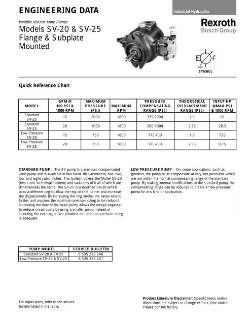
ENGINEERING DATA<br />
Variable Volume Vane Pumps<br />
Models SV-20 & SV-25<br />
Flange & Subplate<br />
Mounted<br />
Quick Reference Chart<br />
Industrial Hydraulics<br />
GPM @ MAXIMUM PRESSURE THEORETICAL INPUT HP<br />
MODEL 100 PSI & PRESSURE MAXIMUM COMPENSATING DISPLACEMENT @MAX PSI<br />
1800 RPM (PSI) RPM RANGE (PSI) RANGE (PSI) & 1800 RPM<br />
Standard<br />
SV-20<br />
15 2000 1800 375-2000 1.9 20<br />
Standard<br />
SV-25<br />
20 1000 1800 300-1000 2.56 20.3<br />
Low Pressure<br />
SV-20<br />
15 750 1800 175-750 1.9 7.25<br />
Low Pressure<br />
SV-25<br />
20 750 1800 175-750 2.56 9.75<br />
STANDARD PUMP – The SV pump is a pressure compensated<br />
vane pump and is available in four basic displacements; one, two,<br />
four and eight cubic inches. This bulletin covers the Model SV-20<br />
(two cubic inch displacement) and variations of it all of which are<br />
dimensionally the same. The SV-25 is a modified SV-20 which<br />
uses a different ring to allow the ring to shift further and increase<br />
the displacement. By increasing the ring stroke, the vanes extend<br />
further and requires the maximum pressure rating to be reduced.<br />
Increasing the flow of the basic pump allows the design engineer<br />
to reduce circuit costs by using a smaller pump instead of<br />
selecting the next larger size provided the reduced pressure rating<br />
is adequate.<br />
PUMP MODEL SERVICE BULLETIN<br />
Standard SV-20 & SV-25 9 535 233 240<br />
Low Pressure SV-25 & SV-25 9 535 233 241<br />
For repair parts, refer to the service<br />
bulletin listed in the table.<br />
SYMBOL<br />
LOW PRESSURE PUMP – On some applications, such as<br />
grinders, the pump must compensate at very low pressures which<br />
are not within the normal compensating range of the standard<br />
pump. By making internal modifications to the standard pump, the<br />
compensating range can be reduced to create a “low pressure”<br />
pump for this kind of application.<br />
Product Literature Disclaimer: Specifications and/or<br />
dimensions are subject to change without prior notice.<br />
Please consult factory.
2 Engineering Data Variable Volume Vane Pumps Models SV-20 & SV-25 <strong>Bosch</strong> <strong>Rexroth</strong><br />
Standard Pump<br />
PRESSURE RATING –<br />
SV-20 – 2000 psi (138 bar)<br />
SV-25 – 1000 psi (69 bar)<br />
PRESSURE COMPENSATING RANGE –<br />
SV-20 – 375-2000 psi (26-138 bar) two stage compensator<br />
300-2000 psi (23-138 bar) single stage compensator<br />
SV-25 – 300-1000 psi (21-69 bar) two stage compensator<br />
280-1000 psi (19-69 bar) single stage compensator<br />
FLOW @ 1800 RPM –<br />
SV-20 – 15 gpm (56.8 l/min) @ 1900 psi<br />
SV-25 – 20.25 gpm (75.7 l/min) @ 900 psi<br />
THEORETICAL DISPLACEMENT –<br />
SV-20 – 2 in 3 /rev (32.8 ml/rev)<br />
SV-25 – 2.6 in 3 /rev (42.6 ml/rev)<br />
MAXIMUM INLET VACUUM AT SEA LEVEL –<br />
6 in. Hg (152 mm Hg)<br />
3 in. Hg (76mm HG) with fluids containing water<br />
MAXIMUM CASE PRESSURE – 10 psi (0.7 bar)<br />
Case drain line should be full intended size (not reduced down).<br />
Case pressure spikes can be minimized by using as straight and<br />
direct path to tank as possible. Other drain lines should not be<br />
connected to the pump drain line. Always terminate the drain line<br />
below the fluid level in the reservoir. Failure to do so will result in<br />
loss of pump prime approximately 30 minutes after it is shut down<br />
and possible introduction of air into the circuit. Case drain line<br />
should be routed to the opposite side of the baffle in relation to<br />
the suction line.<br />
CASE DRAIN FLOW – The values listed below are the average<br />
flows which occur only when the pump is compensating. When<br />
the pump is not compensating, the values are much lower.<br />
100 in 3 /min (1.6 l/min) @ 1000 psi (69 bar)<br />
150 in 3 /min (2.5 l/min) @ 1500 psi (103 bar)<br />
200 in 3 /min (3.3 l/min) @ 2000 psi (138 bar)<br />
DRIVE SPEED RANGE – 750-1800 rpm<br />
(Consult factory Applications department for higher speeds.)<br />
MOUNTING – Available in the following:<br />
Subplate<br />
SAE 2-bolt Flange, side or rear ported (SAE straight thread of 4bolt<br />
Flange Connection.)<br />
ROTATION – Rotation is always determined when viewing the<br />
shaft end. Rotational arrows are cast into the body of all pumps.<br />
Right hand rotation is standard. Left hand rotation pumps are no<br />
longer available.<br />
SEALS – Viton seals are standard. Buna seals are no longer<br />
available.<br />
FILTRATION – A 10 micrometer return line filter is recommended<br />
for increased pump life. If a suction strainer is used, it should not<br />
be finer than 100 mesh (149 micrometer) when using petroleum<br />
fluids. The higher specific gravity of fire resistant fluids and the<br />
higher vapor pressure of water containing fluids will aggravate the<br />
pump inlet conditions. If a suction strainer is used with these<br />
fluids, the mesh must be coarser (60 mesh or 238 micrometer)<br />
than what is used with petroleum oil of the surface area increased<br />
to reduce the pressure drop. <strong>Bosch</strong> <strong>Rexroth</strong> does not<br />
recommend the use of inlet suction strainers.<br />
OVERHUNG LOAD – Radial and axial forces on the shaft are not<br />
recommended. Pump and prime mover should be mounted with<br />
shafts inline (coaxial) and connected with a flexible coupling. Consult<br />
factory Applications department for applications with overhung load.<br />
MAXIMUM ADDITIONAL HP ON THRU SHAFT –<br />
20 HP (15 Kw) @ 1800 rpm<br />
13.25 Hp (10 Kw) @ 1200 rpm<br />
FLUID RECOMMENDATIONS – A premium quality hydraulic oil<br />
with zinc complex anti-wear additives is highly recommended.<br />
Refer to <strong>Bosch</strong> <strong>Rexroth</strong> Group publication 9 535 233 456,<br />
“Petroleum Hydraulic Fluids” for a list of fluids which meet or<br />
exceed the <strong>Bosch</strong> <strong>Rexroth</strong> lubrication requirements.<br />
Optimum<br />
Viscosity<br />
at<br />
Operating<br />
Temperature<br />
Minimum<br />
Maximum<br />
Operating<br />
Viscosity<br />
Operating<br />
Viscosity<br />
Maximum<br />
Start-up<br />
Viscosity<br />
To compensate for the reduced lubrication values of even the<br />
premium quality water containing fluids (glycols and water-in-oil<br />
emulsions), it is necessary to limit system pressure to the values<br />
listed in the table below for an equivalent life.<br />
Water<br />
Glycol<br />
150-250<br />
SUS<br />
( 32-54<br />
cSt)<br />
100<br />
SUS<br />
( 21<br />
cSt)<br />
1000<br />
SUS<br />
( 215<br />
cSt)<br />
4000<br />
SUS<br />
( 864<br />
cSt)<br />
Water-in-Oil<br />
Emulsion<br />
Maximum Pressure<br />
1500 psi<br />
1000psi<br />
Maximum RPM<br />
1800 rpm<br />
1200<br />
rpm<br />
Refer to <strong>Bosch</strong> <strong>Rexroth</strong> Group publication 9 535 233 457, “Fire<br />
Resistant Fluids”, for further details on fluid selection. Fluid<br />
suppliers should be consulted regarding proper fluid maintenance<br />
when using fire resistant fluids containing water.<br />
TEMPERATURE– The temperature of the fluid in the reservoir<br />
should not exceed 130°F (54°C). The pump will operate with fluid<br />
at higher temperatures provided the viscosity is within the<br />
recommended range. under no circumstances should the oil<br />
temperature exceed 160°F (71°C). When using fire resistant fluids<br />
containing water, the fluid temperature should not exceed 120°F<br />
(49°C) to prevent an excessive rate of water evaporation.
<strong>Bosch</strong> <strong>Rexroth</strong><br />
SCREW VOLUME CONTROL– The screw volume control is an<br />
adjustable stop which is used to reduce the maximum pump flow<br />
and is optional. Turning clockwise will reduce the flow in direct<br />
proportion to the displacement of the adjusting screw. During<br />
initial start-up, the flow setting should be at least 50% of the<br />
maximum pump flow.<br />
SV-20 – 1 /4 turn (90°) clockwise will reduce the flow<br />
approximately 2.2 gpm (8.3 l/min) when the pump is<br />
driven at 1800 rpm.<br />
SV-25 – 1 /4 turn (90°) clockwise will reduce the flow<br />
approximately 2.9 gpm (11 l/min) when the pump is<br />
driven at 1800 rpm.<br />
When a volume control is used to reduce the maximum flow of the<br />
pump, the horsepower required to drive the pump is also reduced.<br />
To determine the input HP, use the following formula:<br />
Input = gpm x psi + Deadhead HP at the compensator setting<br />
HP 1714<br />
MOUNTING POSITION – Unrestricted. Caution must be<br />
exercised with vertical mounting to prevent the weight or end<br />
thrust of the prime mover from being applied to the pump shaft.<br />
Low Pressure Pump<br />
NOTE: All of the specifications for the standard pump also<br />
pertain to the low pressure pump except those listed<br />
below.<br />
PRESSURE RATING –<br />
SV-20 – 750 psi (52 bar)<br />
SV-25 – 750 psi (52 bar)<br />
PRESSURE COMPENSATING RANGE –<br />
SV-20 – 175-750 psi (12-52 bar)<br />
SV-25 – 175-750 psi (12-52 bar)<br />
FLOW @ 1800 RPM –<br />
SV-20 – 15 gpm (56.8 l/min) @ 650 psi (45 bar)<br />
SV-25 – 20 gpm (75.7 l/min) @ 650 psi (45 bar)<br />
Engineering Data Variable Volume Vane Pumps Models SV-20 & SV-25 3<br />
SHAFT ALIGNMENT – Shaft alignment should be within 0.003"<br />
total indicator reading. If the shafts are not properly aligned,<br />
increased mechanical noise from the unit will result.<br />
START-UP – To insure priming on initial start-up, air in the pump<br />
and inlet must be allowed to escape. If the pump outlet is normally<br />
blocked, it must be temporarily vented. This can be accomplished<br />
by opening the valve, temporarily cracking a fitting, or installing an<br />
air bleed valve.<br />
CONTROL OPTIONS – Many energy saving controls are available<br />
in addition to the standard two-stage pressure compensator.<br />
Refer to <strong>Bosch</strong> <strong>Rexroth</strong> publication 9 535 233 092 for<br />
performance and dimensional <strong>data</strong>.<br />
COMBINATION MOUNTING – To simplify multi-pump circuits,<br />
adapter kits are available to mount additional pumps in<br />
combination on the rear cover of the flange mounted (side ported)<br />
pumps. Refer to <strong>Bosch</strong> <strong>Rexroth</strong> publication 9 535 233 094 for<br />
horsepower limitations, adapters available, dimensional <strong>data</strong> and<br />
How-To-Order.<br />
WEIGHT (Approximate) –<br />
Subplate Mounted Pump . . . . . . . . . . . . . . . . . . .65 lbs. (29.5 Kg)<br />
Flange Mounted Pump . . . . . . . . . . . . . . . . . . . . .70 lbs. (31.8 Kg)<br />
Add for Screw Volume Control . . . . . . . . . . . . . . . . .1 lb. (0.5 Kg)<br />
Add for Thru Shaft . . . . . . . . . . . . . . . . . . . . . . . . . . . .1lb. (0.5 Kg)<br />
CASE DRAIN FLOW – 210 in 3 /min (3.4 l/min) is the average flow<br />
which will occur only when the pump is compensating at 750 psi<br />
(52 bar). When the pump is not compensating, the values are<br />
much lower.<br />
ROTATION – Right hand only. Clockwise when viewing shaft end.<br />
SEALS – Viton seals are standard.<br />
SCREW VOLUME CONTROL– The screw volume control is standard.
4 Engineering Data Variable Volume Vane Pumps Models SV-20 & SV-25 <strong>Bosch</strong> <strong>Rexroth</strong><br />
Performance Characteristics – Standard Pump
<strong>Bosch</strong> <strong>Rexroth</strong><br />
Engineering Data Variable Volume Vane Pumps Models SV-20 & SV-25 5<br />
Performance Characteristics – Low Pressure Pump
6 Engineering Data Variable Volume Vane Pumps Models SV-20 & SV-25 <strong>Bosch</strong> <strong>Rexroth</strong><br />
Dimensional Data – RH Subplate Mounted
<strong>Bosch</strong> <strong>Rexroth</strong><br />
Engineering Data Variable Volume Vane Pumps Models SV-20 & SV-25 7<br />
Dimensional Data – LH Subplate Mounted<br />
(No longer available)
8 Engineering Data Variable Volume Vane Pumps Models SV-20 & SV-25 <strong>Bosch</strong> <strong>Rexroth</strong><br />
Dimensional Data – RH Flange Mounted, Side Ported
<strong>Bosch</strong> <strong>Rexroth</strong><br />
Engineering Data Variable Volume Vane Pumps Models SV-20 & SV-25 9<br />
Dimensional Data – RH Flange Mounted, Rear Ported
10 Engineering Data Variable Volume Vane Pumps Models SV-20 & SV-25 <strong>Bosch</strong> <strong>Rexroth</strong><br />
Dimensional Data – LH Flange Mounted, Side Ported<br />
(No longer available)
<strong>Bosch</strong> <strong>Rexroth</strong><br />
Engineering Data Variable Volume Vane Pumps Models SV-20 & SV-25 11<br />
Dimensional Data – LH Flange Mounted, Rear Ported<br />
(No longer available)
12 Engineering Data Variable Volume Vane Pumps Models SV-20 & SV-25 <strong>Bosch</strong> <strong>Rexroth</strong><br />
Dimensional Data – Foot Bracket, (PSV-20-70B)<br />
Bolt kit B-90 is included to mount the<br />
pump to the foot bracket. Consists of 2<br />
each 1 /2-13 x 1 1 /4 hex head screw.<br />
The center line height of the shaft of an<br />
electric motor can be determined by<br />
dividing the first two numbers of the motor<br />
frame size by four.<br />
INCHES<br />
(MILLIMETERS)<br />
NOTE:<br />
UNLESS OTHERWISE SPECIFIED<br />
ALL DIMENSIONS ARE NOMINAL.<br />
Dimensional Data – Subplate, (PSV-20-20S-10)<br />
The height of the pump shaft<br />
center line is 6.25 inches<br />
(158.8 mm) when the pump<br />
is mounted to the subplate.<br />
When subplate is not used, a machined<br />
pad as shown by clear area must be<br />
provided for mounting. Pad must be flat<br />
within 0.0003 in/in with a surface finish of<br />
63 RMS.<br />
Bolt kit B-16 is included to mount the<br />
pump to the subplate. Consists of 4 each<br />
7 /16-14 x 1 1 /4 socket head cap screws.<br />
INCHES<br />
(MILLIMETERS)<br />
NOTE:<br />
UNLESS OTHERWISE SPECIFIED<br />
ALL DIMENSIONS ARE NOMINAL.
<strong>Bosch</strong> <strong>Rexroth</strong><br />
CONTROL OPTIONS<br />
P – Standard Pressure Compensator<br />
*S –Solenoid Two-Pressure (Normally<br />
Low, Energize for High Pressure)<br />
*H –Solenoid Two-Pressure (Normally<br />
High, Energize for Low Pressure)<br />
*V – Solenoid Two-Pressure (Normally<br />
Vented, Energize for High Pressure)<br />
J – Hydraulic Two-Pressure (Normally<br />
Low, Energize for High Pressure)<br />
L – Load Sensing<br />
T – Torque Limiting<br />
K – Single Stage Compensator<br />
*Indicate the desired solenoid voltage and<br />
frequency at the end of the pump code.<br />
To order the lock for the compensator adjusting<br />
screw, specify “LOCK” at the end of the code.<br />
Engineering Data Variable Volume Vane Pumps Models SV-20 & SV-25 13<br />
MOUNTING<br />
S – Subplate<br />
A – Flange, Side Ported<br />
(SAE Straight Thread)<br />
B – Flange, Rear Ported<br />
(SAE Straight Thread)<br />
C – Flange, Side Ported<br />
(4 Bolt Flanged Connections)<br />
R – Flange, Rear Ported<br />
(4 Bolt Flanged Connections)<br />
CONTROL OPTIONS<br />
N – No Volume Control<br />
S – Screw Volume Control<br />
MOUNTING<br />
S – Subplate<br />
A – Flange, Side Ported<br />
(SAE Straight Thread)<br />
B – Flange, Rear Ported<br />
(SAE Straight Thread)<br />
C – Flange, Side Ported<br />
(4 Bolt Flanged Connections)<br />
R – Flange, Rear Ported<br />
(4 Bolt Flanged Connections)<br />
VOLUME CONTROL<br />
PSV – PNSF – 20HRM – 56<br />
SEALS<br />
F – Viton Seals<br />
PSV – PSSF – 20DRM – 56<br />
S – Screw Volume Control SEALS<br />
CONTROL<br />
P – Standard Pressure Compensator<br />
F – Viton Seals<br />
How to Order – Standard Pump<br />
DESIGN DIGIT<br />
–56 (Subplate Mounted only)<br />
–66 (Flange Mounted only)<br />
SHAFT<br />
M – Keyed Shaft Medium Length<br />
D – Thru Shaft Medium Length<br />
(Subplate Mounted only)<br />
ROTATION (Viewing Shaft End)<br />
R – Right Hand (Clockwise)<br />
L – Left Hand (Counterclockwise)<br />
PRESSURE RATING<br />
H – 2000 PSI<br />
E – 1000 PSI (SV-25 only)<br />
FLOW<br />
20 – 15 GPM @ 1800 RPM<br />
25 – 20 GPM @ 1800 RPM<br />
SOLENOID VOLTAGE AVAILABLE<br />
110/115 VAC 50/60 Hz (Dual frequency)<br />
220/230 VAC 50/60 Hz (Dual frequency)<br />
12 VDC<br />
24 VDC<br />
For Solenoids with quick connect<br />
(Hirschmann type) consult factory<br />
How to Order – Low Pressure Pump<br />
DESIGN DIGIT<br />
–56 (Subplate Mounted only)<br />
–66 (Flange Mounted only)<br />
SHAFT<br />
M – Keyed Shaft Medium Length<br />
ROTATION (Viewing Shaft End)<br />
R – Right Hand (Clockwise)<br />
PRESSURE RATING<br />
D – 750 PSI<br />
FLOW<br />
20 – 15 GPM @ 1800 RPM<br />
25 – 20 GPM @ 1800 RPM
14 Engineering Data Variable Volume Vane Pumps Models SV-20 & SV-25 <strong>Bosch</strong> <strong>Rexroth</strong><br />
How to Order<br />
Subplate<br />
* Subplate<br />
Model<br />
Number<br />
PSV-20-20S-10<br />
P/<br />
N 725309<br />
Foot Bracket<br />
*<br />
Bracket<br />
Model<br />
Number<br />
PSV-20-70B<br />
P/<br />
N 959770<br />
Flange Kit<br />
Height<br />
of<br />
Pump<br />
Center<br />
Line<br />
When<br />
Mounted<br />
to<br />
Subplate<br />
6.<br />
25<br />
( 158.<br />
8 mm)<br />
* Includes bolt kit B-16 to mount pump to subplate.<br />
Height<br />
of<br />
Pump<br />
Center<br />
Line<br />
When<br />
Mounted<br />
to<br />
Subplate<br />
7.<br />
00<br />
( 177.<br />
8 mm)<br />
* Includes bolt kit B-90 to mount pump to bracket.<br />
F lange<br />
Kit<br />
No.<br />
Consists<br />
of:<br />
1 Ea<br />
– 11<br />
/2 " NPT<br />
Flange<br />
( Inlet)<br />
4 Ea<br />
– 1<br />
/2-13 x 1.<br />
75<br />
Socket<br />
Head<br />
Cap<br />
Screw<br />
PSV-20-20F-60<br />
1 Ea<br />
– 1<br />
/8 x 17<br />
/8 x 21<br />
/8 O-ring<br />
P/<br />
N 953638<br />
1 Ea<br />
– 1"<br />
NPT<br />
FLange<br />
( Outlet)<br />
4 Ea<br />
– 3<br />
/8-16 x 1.<br />
5 Socket<br />
Head<br />
Cap<br />
Screw<br />
1 Ea<br />
– 1<br />
/8 x 11<br />
5/<br />
16 x 19<br />
/ 16 O-ring<br />
Subplate and mounting bolts are not included with<br />
subplate mounted pumps and must be specified in<br />
addition to the pump.<br />
Example: (1) PSV-PNSO-20HRM-56 Pump<br />
(1) PSV-20-20S-10 Subplate<br />
Foot bracket and mounting bolts are not included<br />
with flange mounted pumps and must be specified<br />
in addition to the pump<br />
Example: (1) PSV-PSCO-20HRM-66 Pump<br />
(1) PSV-20-70B Bracket<br />
Flanges are not included with pumps which have 4<br />
bolt flange ports and must be specified in addition<br />
to the pump<br />
Example: (1) PSV-PSCO-20HRM-66 Pump<br />
(1) PSV-20-20F-60 Flange Kit
<strong>Bosch</strong> <strong>Rexroth</strong><br />
Engineering Data Variable Volume Vane Pumps Models SV-20 & SV-25 15
9 535 233 089 4/02<br />
<strong>Bosch</strong> <strong>Rexroth</strong> Corporation<br />
Industrial Hydraulics Division<br />
2315 City Line Road<br />
Bethlehem, PA 18017<br />
Phone (610) 694-8300<br />
Fax (610) 694-8467<br />
www.boschrexroth-us.com<br />
<strong>Bosch</strong> <strong>Rexroth</strong> Corporation*#<br />
Pneumatics<br />
P.O. Box 13597<br />
1953 Mercer Road<br />
Lexington, KY 40511-1021<br />
Phone (859) 254-8032<br />
Fax (859) 254-4188<br />
(800) 489-4188<br />
Email: customer.pneumatics<br />
@boschrexroth-us.com<br />
www.boschrexroth-us.com<br />
<strong>Bosch</strong> <strong>Rexroth</strong> Corporation<br />
Electric Drives and Controls<br />
5150 Prairie Stone Parkway<br />
Hoffman Estates, IL 60192-3707<br />
Phone (847) 645-3600<br />
Fax (847) 645-6201<br />
Email: info@indramat.com<br />
www.boschrexroth-us.com<br />
<strong>Bosch</strong> <strong>Rexroth</strong> Corporation<br />
Linear Motion and<br />
Assembly Technologies<br />
816 East Third Street<br />
Buchanan, MI 49107<br />
Phone (616) 695-0151<br />
Fax (616) 695-5363<br />
www.boschrexroth-us.com<br />
<strong>Bosch</strong> <strong>Rexroth</strong> Corporation*<br />
Mobile Hydraulics Division<br />
P.O. Box 395<br />
1700 Old Mansfield Road<br />
Wooster, OH 44691-0394<br />
Phone (330) 263-3300<br />
Fax (330) 263-3333<br />
Email: info@rexroth.com<br />
www.boschrexroth-us.com<br />
<strong>Bosch</strong> <strong>Rexroth</strong> AG<br />
Zum Eisengiesser 1<br />
D-97816 Lohram Main<br />
Telefon +49 (0) 93 52/18-11<br />
Fax +49 (0) 93 52/18-11 90<br />
Email: pr@rexroth.de<br />
www.boschrexroth.de<br />
*ISO9001 Certified Quality System<br />
#QS9000 Certified Quality System<br />
For more information, you may contact your nearest <strong>Bosch</strong> <strong>Rexroth</strong> distributor: