EMI Shielding Engineering Handbook EMI Shielding - INSCO Group
EMI Shielding Engineering Handbook EMI Shielding - INSCO Group
EMI Shielding Engineering Handbook EMI Shielding - INSCO Group

Create successful ePaper yourself
Turn your PDF publications into a flip-book with our unique Google optimized e-Paper software.
SHIELDING SOLUTIONS FOR WIRELESS COMMUNICATIONS<br />
CHO-VER SHIELD <br />
CHO-VER SHIELD<br />
<strong>EMI</strong> <strong>Shielding</strong> Covers<br />
with Over-Molded Conductive<br />
Elastomer Gasket<br />
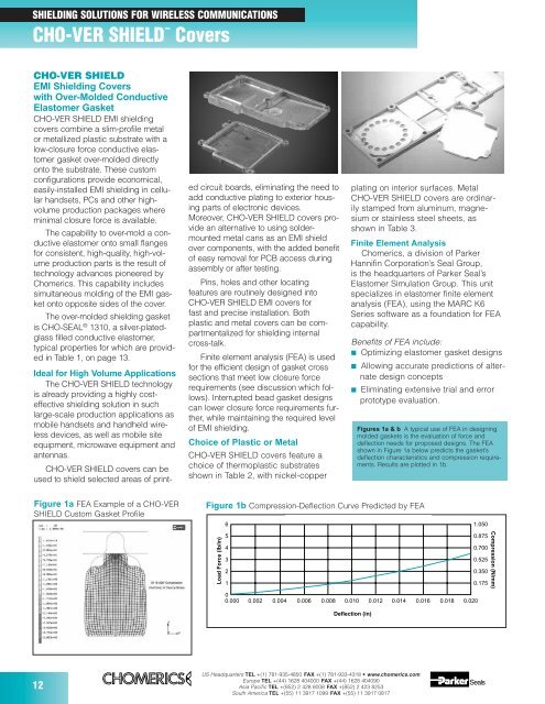
CHO-VER SHIELD <strong>EMI</strong> shielding<br />
covers combine a slim-profile metal<br />
or metallized plastic substrate with a<br />
low-closure force conductive elastomer<br />
gasket over-molded directly<br />
onto the substrate. These custom<br />
configurations provide economical,<br />
easily-installed <strong>EMI</strong> shielding in cellular<br />
handsets, PCs and other highvolume<br />
production packages where<br />
minimal closure force is available.<br />
The capability to over-mold a conductive<br />
elastomer onto small flanges<br />
for consistent, high-quality, high-volume<br />
production parts is the result of<br />
technology advances pioneered by<br />
Chomerics. This capability includes<br />
simultaneous molding of the <strong>EMI</strong> gasket<br />
onto opposite sides of the cover.<br />
The over-molded shielding gasket<br />
is CHO-SEAL ® 1310, a silver-platedglass<br />
filled conductive elastomer,<br />
typical properties for which are provided<br />
in Table 1, on page 13.<br />
Ideal for High Volume Applications<br />
The CHO-VER SHIELD technology<br />
is already providing a highly costeffective<br />
shielding solution in such<br />
large-scale production applications as<br />
mobile handsets and handheld wireless<br />
devices, as well as mobile site<br />
equipment, microwave equipment and<br />
antennas.<br />
CHO-VER SHIELD covers can be<br />
used to shield selected areas of print-<br />
Figure 1a FEA Example of a CHO-VER<br />
SHIELD Custom Gasket Profile<br />
12<br />
Covers<br />
ed circuit boards, eliminating the need to<br />
add conductive plating to exterior housing<br />
parts of electronic devices.<br />
Moreover, CHO-VER SHIELD covers provide<br />
an alternative to using soldermounted<br />
metal cans as an <strong>EMI</strong> shield<br />
over components, with the added benefit<br />
of easy removal for PCB access during<br />
assembly or after testing.<br />
Pins, holes and other locating<br />
features are routinely designed into<br />
CHO-VER SHIELD <strong>EMI</strong> covers for<br />
fast and precise installation. Both<br />
plastic and metal covers can be compartmentalized<br />
for shielding internal<br />
cross-talk.<br />
Finite element analysis (FEA) is used<br />
for the efficient design of gasket cross<br />
sections that meet low closure force<br />
requirements (see discussion which follows).<br />
Interrupted bead gasket designs<br />
can lower closure force requirements further,<br />
while maintaining the required level<br />
of <strong>EMI</strong> shielding.<br />
Choice of Plastic or Metal<br />
CHO-VER SHIELD covers feature a<br />
choice of thermoplastic substrates<br />
shown in Table 2, with nickel-copper<br />
Load Force (lb/in)<br />
US Headquarters TEL +(1) 781-935-4850 FAX +(1) 781-933-4318 • www.chomerics.com<br />
Europe TEL +(44) 1628 404000 FAX +(44) 1628 404090<br />
Asia Pacific TEL +(852) 2 428 8008 FAX +(852) 2 423 8253<br />
South America TEL +(55) 11 3917 1099 FAX +(55) 11 3917 0817<br />
plating on interior surfaces. Metal<br />
CHO-VER SHIELD covers are ordinarily<br />
stamped from aluminum, magnesium<br />
or stainless steel sheets, as<br />
shown in Table 3.<br />
Finite Element Analysis<br />
Chomerics, a division of Parker<br />
Hannifin Corporation’s Seal <strong>Group</strong>,<br />
is the headquarters of Parker Seal’s<br />
Elastomer Simulation <strong>Group</strong>. This unit<br />
specializes in elastomer finite element<br />
analysis (FEA), using the MARC K6<br />
Series software as a foundation for FEA<br />
capability.<br />
Benefits of FEA include:<br />
■ Optimizing elastomer gasket designs<br />
■ Allowing accurate predictions of alternate<br />
design concepts<br />
■ Eliminating extensive trial and error<br />
prototype evaluation.<br />
Figure 1b Compression-Deflection Curve Predicted by FEA<br />
Figures 1a & b A typical use of FEA in designing<br />
molded gaskets is the evaluation of force and<br />
deflection needs for proposed designs. The FEA<br />
shown in Figure 1a below predicts the gasket’s<br />
deflection characteristics and compression requirements.<br />
Results are plotted in 1b.<br />
Compression-Deflection Curve Predicted by FEA<br />
6<br />
1.050<br />
5<br />
0.875<br />
4<br />
0.700<br />
3<br />
0.525<br />
2<br />
0.350<br />
1<br />
0<br />
0.175<br />
0.000 0.002 0.004 0.006 0.008 0.010 0.012 0.014 0.016 0.018 0.020<br />
Deflection (in)<br />
Compression (N/mm)