EMI Shielding Engineering Handbook EMI Shielding - INSCO Group
EMI Shielding Engineering Handbook EMI Shielding - INSCO Group
EMI Shielding Engineering Handbook EMI Shielding - INSCO Group

You also want an ePaper? Increase the reach of your titles
YUMPU automatically turns print PDFs into web optimized ePapers that Google loves.
<strong>EMI</strong> <strong>Shielding</strong>/Grounding Spacer Gaskets continued<br />
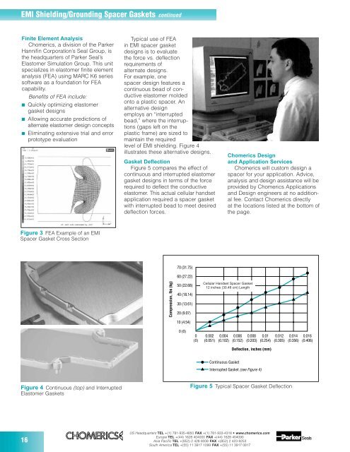
Finite Element Analysis<br />
Chomerics, a division of the Parker<br />
Hannifin Corporation’s Seal <strong>Group</strong>, is<br />
the headquarters of Parker Seal’s<br />
Elastomer Simulation <strong>Group</strong>. This unit<br />
specializes in elastomer finite element<br />
analysis (FEA) using MARC K6 series<br />
software as a foundation for FEA<br />
capability.<br />
16<br />
Benefits of FEA include:<br />
■ Quickly optimizing elastomer<br />
gasket designs<br />
■ Allowing accurate predictions of<br />
alternate elastomer design concepts<br />
■ Eliminating extensive trial and error<br />
prototype evaluation<br />
Figure 3 FEA Example of an <strong>EMI</strong><br />
Spacer Gasket Cross Section<br />
Figure 4 Continuous (top) and Interrupted<br />
Elastomer Gaskets<br />
Typical use of FEA<br />
in <strong>EMI</strong> spacer gasket<br />
designs is to evaluate<br />
the force vs. deflection<br />
requirements of<br />
alternate designs.<br />
For example, one<br />
spacer design features a<br />
continuous bead of conductive<br />
elastomer molded<br />
onto a plastic spacer. An<br />
alternative design<br />
employs an “interrupted<br />
bead,” where the interruptions<br />
(gaps left on the<br />
plastic frame) are sized to<br />
maintain the required<br />
level of <strong>EMI</strong> shielding. Figure 4<br />
illustrates these alternative designs.<br />
Gasket Deflection<br />
Figure 5 compares the effect of<br />
continuous and interrupted elastomer<br />
gasket designs in terms of the force<br />
required to deflect the conductive<br />
elastomer. This actual cellular handset<br />
application required a spacer gasket<br />
with interrupted bead to meet desired<br />
deflection forces.<br />
Compression, lbs (kg)<br />
70 (31.75)<br />
60 (27.22)<br />
50 (22.68)<br />
40 (18.14)<br />
30 (13.61)<br />
20 (9.07)<br />
10 (4.54)<br />
0 (0)<br />
0<br />
(0)<br />
0.002<br />
(0.051)<br />
0.004<br />
(0.102)<br />
US Headquarters TEL +(1) 781-935-4850 FAX +(1) 781-933-4318 • www.chomerics.com<br />
Europe TEL +(44) 1628 404000 FAX +(44) 1628 404090<br />
Asia Pacific TEL +(852) 2 428 8008 FAX +(852) 2 423 8253<br />
South America TEL +(55) 11 3917 1099 FAX +(55) 11 3917 0817<br />
Chomerics Design<br />
and Application Services<br />
Chomerics will custom design a<br />
spacer for your application. Advice,<br />
analysis and design assistance will be<br />
provided by Chomerics Applications<br />
and Design engineers at no additional<br />
fee. Contact Chomerics directly<br />
at the locations listed at the bottom of<br />
the page.<br />
Cellular Handset Spacer Gasket<br />
12 inches (30.48 cm) Length<br />
0.006<br />
(0.152)<br />
0.008<br />
(0.203)<br />
0.01<br />
(0.254)<br />
Deflection, inches (mm)<br />
Continuous Gasket<br />
Interrupted Gasket (see Figure 4)<br />
0.012<br />
(0.305)<br />
Figure 5 Typical Spacer Gasket Deflection<br />
0.014<br />
(0.356)<br />
0.016<br />
(0.406)