EMI Shielding Engineering Handbook EMI Shielding - INSCO Group
EMI Shielding Engineering Handbook EMI Shielding - INSCO Group
EMI Shielding Engineering Handbook EMI Shielding - INSCO Group
You also want an ePaper? Increase the reach of your titles
YUMPU automatically turns print PDFs into web optimized ePapers that Google loves.
Cho-Form ® Robotically Dispensed Gasketing continued<br />
Critical Housing<br />
Design Issues<br />
Cho-Form FIP gasket technology<br />
accommodates a reasonable<br />
degree of variability in housing<br />
part dimensions. However, setup<br />
and dispensing speed are directly<br />
impacted by part uniformity. In<br />
addition, the housing design can<br />
pose obstacles to efficient gasket<br />
dispensing.<br />
The most common avoidable problem<br />
is warped or non-uniform<br />
housings. If housings are not sufficiently<br />
flat and dimensionally uniform,<br />
they must be restrained by<br />
special alignment and hold-down<br />
fixtures, which can add substantial<br />
setup time.<br />
For best results and production<br />
economics, designs should reflect<br />
the following considerations:<br />
Positive Locating Features<br />
Speed Production<br />
Parts should be easily fixtured for<br />
fast, accurate dispensing<br />
Reproducible positioning of the parts<br />
beneath the dispensing head is<br />
fundamental to this automated technology.<br />
Maximum production speed<br />
can be achieved when through-holes<br />
are available to pin-position parts on<br />
the pallets that transport them to the<br />
dispensing head. If through-holes are<br />
not available, two sides can be<br />
pushed against pallet rails for positioning.<br />
This requires hold-down<br />
clamps that must be positioned without<br />
interfering with the dispensing<br />
needle.<br />
Avoid features that complicate<br />
design of a locating system<br />
Parting lines in dies or molds can interfere<br />
with the establishment of a locating<br />
edge. Mold gates, runners or flash<br />
can interfere with positioning pins or<br />
fixtures.<br />
Part Reproducibility is Critical<br />
Flanges, rails or ribs to be gasketed<br />
should have part-to-part location<br />
reproducibility (X and Y dimensions)<br />
within 0.008 inch (0.20 mm)<br />
Once the dispense path is programmed,<br />
all surfaces to be gasketed<br />
must be located where the program<br />
assumes them to be. Variation greater<br />
than 0.008 inch (0.203 mm) will result<br />
24<br />
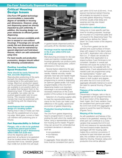
in gasket beads dispensed partly on<br />
and partly off the intended surfaces.<br />
Housings must be reproducible<br />
in the Z axis within 0.012 inch<br />
(0.30 mm)<br />
Manufacturing processes for die-cast<br />
metal and injection molded plastic<br />
housings generally can produce parts<br />
with intrinsically reproducible, uniform<br />
dimensions in the Z axis.<br />
Several factors determine the gasket<br />
bead profile — air pressure in the<br />
needle, material viscosity, needle<br />
diameter, feed rate and needle height<br />
(Z) above the part. Accurate Z-axis<br />
programming is central to dispensing<br />
an optimum gasket profile. Full 3-axis<br />
programmability of the Cho-Form<br />
dispensing heads is an important<br />
advantage in accommodating the<br />
necessary tolerances on the Z-axis<br />
position of the surface to be gasketed.<br />
Selection of a housing supplier able<br />
to meet the reproducibility requirements<br />
for the Z-axis can make a real<br />
difference in the quality, speed and<br />
economics of gasket dispensing.<br />
Production housing functions as<br />
master<br />
The Cho-Form gasket dispensing<br />
head is programmed in 3 axes by<br />
plotting the path which the needle will<br />
follow, using a representative production<br />
housing as the master. Programming<br />
can account for unintended but<br />
consistent deviations in elevation,<br />
such as:<br />
• non-parallelism<br />
• non-flatness<br />
• warping<br />
In aggregate, these elevation deviations<br />
must be consistent from part to<br />
US Headquarters TEL +(1) 781-935-4850 FAX +(1) 781-933-4318 • www.chomerics.com<br />
Europe TEL +(44) 1628 404000 FAX +(44) 1628 404090<br />
Asia Pacific TEL +(852) 2 428 8008 FAX +(852) 2 423 8253<br />
South America TEL +(55) 11 3917 1099 FAX +(55) 11 3917 0817<br />
part within 0.012 inch (0.30 mm). If not,<br />
special mechanical restraint fixturing<br />
will probably be required to ensure<br />
accurate gasket dispensing. Fixturing<br />
schemes usually entail delay and<br />
expense and may also impact<br />
production speed.<br />
Parallelism to a defined plane<br />
Using one or more specific part features<br />
for locating purposes, housings<br />
are mounted on a machined pallet and<br />
conveyed to the dispensing head. The<br />
pallet surface defines the “datum<br />
plane” for Z-axis motion of the dispensing<br />
needle.<br />
A Cho-Form gasket can be dispensed<br />
onto a part surface of known<br />
slope with respect to the datum plane<br />
(up to 80°). Application onto a flat surface<br />
(i.e., 0° slope) can actually be<br />
more difficult than application to a<br />
sloped surface if part thickness is not<br />
consistent. Variation in overall part<br />
thickness will cause the surface to be<br />
gasketed to be non-parallel with the<br />
datum plane. Z-axis adjustments to the<br />
needle’s path are programmed using<br />
the representative “master” part.<br />
However, these variations must be consistent<br />
in both location and degree,<br />
and within the 0.012 inch (0.30 mm)<br />
aggregate allowable tolerance to avoid<br />
the need for special fixturing. (Figures<br />
6 a-b.)<br />
Flatness of the surface to be<br />
gasketed<br />
Unevenness in flanges, rails or ribs to<br />
be gasketed can be programmed into<br />
the Z-axis motion of the dispensing<br />
head. Again, this Z-axis variation must<br />
be consistent from part-to-part within<br />
the 0.012 inch (0.30 mm) aggregate tolerance<br />
to avoid the need for fixturing.<br />
(Figures 7a-b.)<br />
Warping of the housing<br />
As with parallelism and flatness of the<br />
surface to be gasketed, warping of the<br />
entire part can contribute to a Z-axis<br />
variation that exceeds the 0.012 inch<br />
(0.30 mm) tolerance for reproducibility.<br />
The trend toward smaller electronic<br />
packages with thin housing walls<br />
makes this a common occurrence. If<br />
surfaces for part hold-down are available,<br />
this condition can be accommodated<br />
by fixturing. However, setup and<br />
production time will be affected.


