European Technical Approval ETA-12/0087 - ETA-Danmark
European Technical Approval ETA-12/0087 - ETA-Danmark
European Technical Approval ETA-12/0087 - ETA-Danmark

Create successful ePaper yourself
Turn your PDF publications into a flip-book with our unique Google optimized e-Paper software.
<strong>ETA</strong>-<strong>Danmark</strong> A/S<br />
Kollegievej 6<br />
DK-2920 Charlottenlund<br />
Tel. +45 72 24 59 00<br />
Fax +45 72 24 59 04<br />
Internet www.etadanmark.dk<br />
Authorised and notified according to<br />
Article 10 of the Council Directive<br />
89/106/EEC of 21 December 1988 on<br />
the approximation of laws, regulations<br />
and administrative provisions of<br />
Member States relating to construction<br />
products<br />
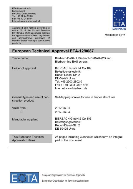
<strong>European</strong> <strong>Technical</strong> <strong>Approval</strong> <strong>ETA</strong>-<strong>12</strong>/<strong>0087</strong><br />
Trade name:<br />
Holder of approval:<br />
Generic type and use of construction<br />
product:<br />
Valid from:<br />
to:<br />
Manufacturing plant:<br />
This <strong>European</strong> <strong>Technical</strong><br />
<strong>Approval</strong> contains:<br />
Bierbach-DaBAU, Bierbach-DaBAU-WD and<br />
Bierbach-Ing-BAU screws<br />
BiERBACH GmbH & Co. KG<br />
Befestigungstechnik<br />
Rudolf-Diesel-Str. 2<br />
DE-59425 Unna<br />
Tel. +49 2303 2802 0<br />
Fax + +49 2303 2802 <strong>12</strong>9<br />
Internet www.bierbach.de<br />
MEMBER OF EOTA<br />
Self-tapping screws for use in timber structures<br />
20<strong>12</strong>-06-04<br />
2017-06-04<br />
BiERBACH GmbH & Co. KG<br />
Befestigungstechnik<br />
Rudolf-Diesel-Str. 2<br />
DE-59425 Unna<br />
26 pages including 3 annexes which form an integral<br />
part of the document
Page 2 of 26 of <strong>European</strong> <strong>Technical</strong> <strong>Approval</strong> no. <strong>ETA</strong>-<strong>12</strong>/<strong>0087</strong><br />
I LEGAL BASIS AND GENERAL<br />
CONDITIONS<br />
1 This <strong>European</strong> <strong>Technical</strong> <strong>Approval</strong> is issued by<br />
<strong>ETA</strong>-<strong>Danmark</strong> A/S in accordance with:<br />
- Council Directive 89/106/EEC of 21 December<br />
1988 on the approximation of laws, regulations<br />
and administrative provisions of Member States<br />
relating to construction products 1) , as amended by<br />
Council Directive 93/68/EEC of 22 July 1993 2) .<br />
- Bekendtgørelse 559 af 27-06-1994 (afløser<br />
bekendtgørelse 480 af 25-06-1991) om ikrafttræden<br />
af EF direktiv af 21. december 1988 om<br />
indbyrdes tilnærmelse af medlemsstaternes love<br />
og administrative bestemmelser om byggevarer.<br />
- Common Procedural Rules for Requesting,<br />
Preparing and the Granting of <strong>European</strong> <strong>Technical</strong><br />
<strong>Approval</strong>s set out in the Annex to Commission<br />
Decision 94/23/EC 3) .<br />
2 <strong>ETA</strong>-<strong>Danmark</strong> A/S is authorized to check whether<br />
the provisions of this <strong>European</strong> <strong>Technical</strong><br />
<strong>Approval</strong> are met. Checking may take place in the<br />
manufacturing plant. Nevertheless, the responsibility<br />
for the conformity of the products to the<br />
<strong>European</strong> <strong>Technical</strong> <strong>Approval</strong> and for their fitness<br />
for the intended use remains with the holder of<br />
the <strong>European</strong> <strong>Technical</strong> <strong>Approval</strong>.<br />
3 This <strong>European</strong> <strong>Technical</strong> <strong>Approval</strong> is not to be<br />
transferred to manufacturers or agents of manufacturers<br />
other than those indicated on page 1, or<br />
manufacturing plants other than those indicated<br />
on page 1 of this <strong>European</strong> <strong>Technical</strong> <strong>Approval</strong>.<br />
4 This <strong>European</strong> <strong>Technical</strong> <strong>Approval</strong> may be<br />
withdrawn by <strong>ETA</strong>-<strong>Danmark</strong> A/S pursuant to<br />
Article 5(1) of Council Directive89/106/EEC.<br />
1) Official Journal of the <strong>European</strong> Communities N o L40, 11 Feb 1989, p <strong>12</strong>.<br />
2) Official Journal of the <strong>European</strong> Communities N o L220, 30 Aug 1993, p 1.<br />
3) Official Journal of the <strong>European</strong> Communities N o L 17, 20 Jan 1994, p 34.<br />
5 Reproduction of this <strong>European</strong> <strong>Technical</strong> <strong>Approval</strong><br />
including transmission by electronic means shall be<br />
in full. However, partial reproduction can be made<br />
with the written consent of <strong>ETA</strong>-<strong>Danmark</strong> A/S. In<br />
this case partial reproduction has to be designated as<br />
such. Texts and drawings of advertising brochures<br />
shall not contradict or misuse the <strong>European</strong> <strong>Technical</strong><br />
<strong>Approval</strong>.<br />
6 This <strong>European</strong> <strong>Technical</strong> <strong>Approval</strong> is issued by <strong>ETA</strong>-<br />
<strong>Danmark</strong> A/S in English.<br />
This version corresponds fully to the version circulated<br />
within EOTA. Translations into other languages<br />
have to be designated as such.
Page 3 of 26 of <strong>European</strong> <strong>Technical</strong> <strong>Approval</strong> no. <strong>ETA</strong>-<strong>12</strong>/<strong>0087</strong><br />
II SPECIAL CONDITIONS OF THE<br />
EUROPEAN TECHNICAL APPROVAL<br />
1 Definition of product and intended use<br />
Bierbach DaBau, DaBau WD and IngBau screws are selftapping<br />
screws to be used in timber structures. Bierbach<br />
screws shall be threaded over a part of the length. The<br />
screws shall be produced from carbon steel wire for<br />
nominal diameters of 6,0 mm to 10,0 mm and from<br />
stainless steel wire for nominal diameters of 6,0 mm to 8,0<br />
mm. Where corrosion protection is required, the material or<br />
coating shall be declared in accordance with the relevant<br />
specification given in Annex A of EN 14592.<br />
Geometry and Material<br />
The nominal diameter (outer thread diameter), d, shall not be<br />
less than 6,0 mm and shall not be greater than 10,0 mm. The<br />
overall length, L, of screws shall not be less than 60 mm and<br />
shall not be greater than 600 mm. Other dimensions are<br />
given in Annex A.<br />
The ratio of inner thread diameter to outer thread diameter<br />
di/d ranges from 0,60 to 0,70.<br />
The screws are threaded over a minimum length lg of 6,6·d<br />
(i.e. lg > 6,6·d).<br />
The lead p (distance between two adjacent thread flanks)<br />
ranges from 0,43·d to 0,91·d.<br />
No breaking of scews shall be observed at a bend angle, α,<br />
of less than (45/d 0,7 + 20) degrees.<br />
Intended use<br />
The screws are used for connections in load bearing timber<br />
structures between members of solid timber (softwood),<br />
glued laminated timber, cross-laminated timber, and<br />
laminated veneer lumber, similar glued members, woodbased<br />
panels or steel.<br />
Bierbach DaBau and DaBau WD screws are exclusively,<br />
Bierbach IngBau screws may be used for the fixing of<br />
thermal insulation material on rafters or facades.<br />
Steel plates and wood-based panels except solid wood<br />
panels, laminated veneer lumber and cross laminated timber<br />
shall only be located on the side of the screw head. The<br />
following wood-based panels may be used:<br />
- Plywood according to EN 636 or <strong>European</strong> <strong>Technical</strong><br />
<strong>Approval</strong> or national provisions that apply at the<br />
installation site<br />
- Particleboard according to EN 3<strong>12</strong> or <strong>European</strong><br />
<strong>Technical</strong> <strong>Approval</strong> or national provisions that apply<br />
at the installation site<br />
- Oriented Strand Board according to EN 300 or<br />
<strong>European</strong> <strong>Technical</strong> <strong>Approval</strong> or national provisions<br />
that apply at the installation site<br />
- Fibreboard according to EN 622-2 and 622-3 or<br />
<strong>European</strong> <strong>Technical</strong> <strong>Approval</strong> (minimum density 650<br />
kg/m³) or national provisions that apply at the<br />
installation site<br />
- Cement bonded particleboard according to EN 634 or<br />
<strong>European</strong> <strong>Technical</strong> <strong>Approval</strong> or national provisions<br />
that apply at the installation site<br />
- Solid wood panels according to EN 13353 and EN<br />
13986 or <strong>European</strong> <strong>Technical</strong> <strong>Approval</strong> or national<br />
provisions that apply at the installation site<br />
- Cross laminated timber according to <strong>European</strong><br />
<strong>Technical</strong> <strong>Approval</strong><br />
- Laminated Veneer Lumber according to EN 14374 or<br />
<strong>European</strong> <strong>Technical</strong> <strong>Approval</strong><br />
- Engineered wood products according to <strong>European</strong><br />
<strong>Technical</strong> <strong>Approval</strong> if the <strong>ETA</strong> of the product includes<br />
provisions for the use of self-tapping screws, the<br />
provisions of the <strong>ETA</strong> of the engineered wood product<br />
apply<br />
The screws shall be driven into the wood without predrilling<br />
or after pre-drilling with a diameter not larger than<br />
the inner thread diameter for the length of the threaded part<br />
and with a maximum of the smooth shank diameter for the<br />
length of the smooth shank.<br />
The screws are intended to be used in timber connections for<br />
which requirements for mechanical resistance and stability<br />
and safety in use in the sense of the Essential Requirements 1<br />
and 4 of Council Directive 89/106/EEC shall be fulfilled.<br />
The design of the connections shall be based on the<br />
characteristic load-carrying capacities of the screws. The<br />
design capacities shall be derived from the characteristic<br />
capacities in accordance with Eurocode 5 or an appropriate<br />
national code.<br />
The screws are intended for use for connections subject to<br />
static or quasi static loading.<br />
The scope of the screws regarding resistance to corrosion<br />
shall be defined according to national provisions that apply<br />
at the installation site considering environmental<br />
conditions. Section 2.7 of this <strong>ETA</strong> contains the corrosion<br />
protection for Bierbach screws made from carbon steel and<br />
the material number of the stainless steel..<br />
Assumed working life<br />
The assumed intended working life of the screws for the<br />
intended use is 50 years, provided that they are subject to<br />
appropriate use and maintenance.<br />
The information on the working life should not be regarded<br />
as a guarantee provided by the manufacturer or the approval<br />
body issuing the <strong>ETA</strong>. An “assumed intended working life”<br />
means that it is expected that, when this working life has<br />
elapsed, the real working life may be, in normal use<br />
conditions, considerably longer without major degradation<br />
affecting the essential requirements.
Page 4 of 26 of <strong>European</strong> <strong>Technical</strong> <strong>Approval</strong> no. <strong>ETA</strong>-<strong>12</strong>/<strong>0087</strong><br />
2 Characteristics of product and assessment<br />
Characteristic<br />
2.1 Mechanical resistance and stability*)<br />
2.1.1<br />
2.1.2<br />
2.1.3<br />
2.2 Safety in case of fire<br />
2.2.1<br />
Tensile strength<br />
Screws made of hardened carbon steel<br />
Screws made of stainless or non-hardened<br />
carbon steel<br />
Insertion moment<br />
Torsional strength<br />
Screws made of hardened carbon steel<br />
Screws made of stainless or non-hardened<br />
carbon steel<br />
Reaction to fire<br />
2.3 Hygiene, health and the environment<br />
2.3.1<br />
2.4 Safety in use<br />
2.5 Protection against noise<br />
Influence on air quality<br />
2.6 Energy economy and heat retention<br />
2.7 Related aspects of serviceability<br />
2.7.1<br />
2.7.2<br />
2.7.3<br />
Durability<br />
Serviceability<br />
Identification<br />
Assessment of characteristic<br />
Characteristic value ftens,k:<br />
d = 6,0 mm: 13 kN<br />
d = 8,0 mm: 25 kN<br />
d = 10,0 mm: 28 kN<br />
d = 6,0 mm: 7 kN<br />
d = 8,0 mm: 13 kN<br />
Ratio of the characteristic torsional strength to<br />
the mean insertion moment:<br />
ftor,k / Rtor,mean > 1,5<br />
Characteristic value ftor,k:<br />
d = 6,0 mm: <strong>12</strong> Nm<br />
d = 8,0 mm: 33 Nm<br />
d = 10,0 mm: 45 Nm<br />
d = 6,0 mm: 8 Nm<br />
d = 8,0 mm: 18 Nm<br />
The screws are made from steel classified as<br />
Euroclass A1 in accordance with EN 1350-1<br />
and EC decision 96/603/EC, amended by EC<br />
Decision 2000/605/EC<br />
No dangerous materials **)<br />
Not relevant<br />
Not relevant<br />
Not relevant<br />
The screws have been assessed as having<br />
satisfactory durability and serviceability when<br />
used in timber structures using the timber<br />
species described in Eurocode 5 and subject to<br />
the conditions defined by service classes 1 and 2<br />
See Annex A<br />
*) See page 5 of the <strong>ETA</strong><br />
**) In accordance with http://europa.eu.int-/comm/enterprise/construction/internal/dangsub/dangmain.htm In addition to the specific clauses relating to dangerous<br />
substances contained in this <strong>European</strong> <strong>Technical</strong> <strong>Approval</strong>, there may be other requirements applicable to the products falling within its scope (e.g. transposed <strong>European</strong><br />
legislation and national laws, regulations and administrative provisions). In order to meet the provisions of the EU Construction Products Directive, these requirements need<br />
also to be complied with, when and where they apply.
Page 5 of 26 of <strong>European</strong> <strong>Technical</strong> <strong>Approval</strong> no. <strong>ETA</strong>-<strong>12</strong>/<strong>0087</strong><br />
2.1 Mechanical resistance and stability<br />
The load-carrying capacities for Bierbach screws are<br />
applicable to the wood-based materials mentioned in<br />
paragraph 1 even though the term timber has been used in<br />
the following.<br />
The characteristic lateral load-carrying capacities and the<br />
characteristic axial withdrawal capacities of Bierbach<br />
screws should be used for designs in accordance with<br />
Eurocode 5 or an appropriate national code.<br />
Point side penetration length must be lef > 4·d, where d is<br />
the outer thread diameter of the screw. For the fixing of<br />
rafters, point side penetration must be at least 40 mm, lef ><br />
40 mm.<br />
<strong>European</strong> <strong>Technical</strong> <strong>Approval</strong>s for structural members or<br />
wood-based panels must be considered where applicable.<br />
Lateral load-carrying capacity<br />
The characteristic lateral load-carrying capacity of Bierbach<br />
screws shall be calculated according to EN 1995-1-1:2008<br />
(Eurocode 5) using the outer thread diameter d as the<br />
nominal diameter of the screw. The contribution from the<br />
rope effect may be considered.<br />
The characteristic yield moment shall be assumed as:<br />
Bierbach screws made of hardened carbon steel:<br />
d = 6,0 mm: My,k = 10 Nm<br />
d = 8,0 mm: My,k = 25 Nm<br />
d = 10,0 mm: My,k = 36 Nm<br />
Bierbach screws made of stainless or non-hardened carbon<br />
steel:<br />
d = 6,0 mm: My,k = 7 Nm<br />
d = 8,0 mm: My,k = 15 Nm<br />
The embedding strength for screws arranged parallel to the<br />
plane of cross laminated timber, independent of the angle<br />
between screw axis and grain direction, 0° ≤ α ≤ 90°, shall<br />
be calculated from:<br />
0,5<br />
f 20 d −<br />
= ⋅ [N/mm²]<br />
h,k<br />
unless otherwise specified in the technical specification<br />
(<strong>ETA</strong> or hEN) for the cross laminated timber.<br />
Where<br />
d outer thread diameter [mm]<br />
The embedding strength for screws in the wide face of<br />
cross laminated timber should be assumed as for solid<br />
timber based on the characteristic density of the outer layer.<br />
If relevant, the angle between force and grain direction of<br />
the outer layer should be taken into account.<br />
The direction of the lateral force shall be perpendicular to<br />
the screw axis and parallel to the wide face of the cross<br />
laminated timber.<br />
For angles 45° ≤ α < 90° between force and grain direction<br />
of the outer layer the characteristic load-carrying capacity<br />
may be assumed as 2/3 of the corresponding value for α =<br />
90°, if only the penetration depth perpendicular to the wide<br />
face is taken into account.<br />
Axial withdrawal capacity<br />
The characteristic axial withdrawal capacity of Bierbach<br />
screws in solid timber (softwood), glued laminated timber<br />
cross-laminated timber or laminated veneer lumber members<br />
at an angle of 30° < α < 90° to the grain shall be calculated<br />
according to EN 1995-1-1:2008 from:<br />
0,8<br />
nef ⋅ fax,k ⋅d ⋅l ef ⎛ ρk<br />
⎞<br />
Fax,<br />
α,Rk<br />
= ⋅ 2 2 ⎜ ⎟<br />
[N]<br />
1,2 ⋅ cos α + sin α ⎝ 350 ⎠<br />
Where<br />
Fax,α,RK characteristic withdrawal capacity of the<br />
screw at an angle α to the grain [N]<br />
effective number of screws according to EN<br />
nef<br />
fax,k<br />
1995-1-1:2008<br />
Characteristic withdrawal parameter<br />
Screw d = 6,0 mm: fax,k = 10 N/mm²<br />
Screw d = 8,0 mm: fax,k = <strong>12</strong> N/mm²<br />
Screw d = 10,0 mm: fax,k = 10 N/mm²<br />
d outer thread diameter [mm]<br />
lef Penetration length of the threaded part<br />
according to EN 1995-1-1:2008 [mm]<br />
α Angle between grain and screw axis (α > 30°)<br />
Characteristic density [kg/m³]<br />
ρk<br />
For screws penetrating more than one layer of cross<br />
laminated timber, the different layers may be taken into<br />
account proportionally.<br />
The axial withdrawal capacity is limited by the head pullthrough<br />
capacity and the tensile or compressive capacity of<br />
the screw.<br />
Head pull-through capacity<br />
The characteristic head pull-through capacity of Bierbach<br />
screws shall be calculated according to EN 1995-1-<br />
1:2008 from:<br />
2 ⎛ ρk<br />
⎞<br />
Fax, α,Rk<br />
= nef ⋅f head,k ⋅d h ⋅⎜ ⎟<br />
[N]<br />
⎝ 350 ⎠<br />
where:<br />
Fax,α,RK characteristic head pull-through capacity of<br />
the connection at an angle α > 30° to the<br />
grain [N]<br />
nef effective number of screws according to EN<br />
1995-1-1:2008<br />
fhead,k characteristic head pull-through parameter<br />
[N/mm²]<br />
dh diameter of the screw head or the washer<br />
[mm]. Outer diameter of washers dk > 32 mm<br />
shall not be considered.<br />
0,8
ρk<br />
Page 6 of 26 of <strong>European</strong> <strong>Technical</strong> <strong>Approval</strong> no. <strong>ETA</strong>-<strong>12</strong>/<strong>0087</strong><br />
characteristic density [kg/m³], for wood-based<br />
panels ρk = 380 kg/m³<br />
Characteristic head pull-through parameter for screws in<br />
connections with timber and in connections with woodbased<br />
panels with thicknesses above 20 mm:<br />
fhead,k = <strong>12</strong>,0 N/mm²<br />
Characteristic head pull-through parameter for screws in<br />
connections with wood-based panels with thicknesses<br />
between <strong>12</strong> mm and 20 mm:<br />
fhead,k = 8 N/mm²<br />
Screws in connections with wood-based panels with a<br />
thickness below <strong>12</strong> mm (minimum thickness of the wood<br />
based panels of 1,2·d with d as outer thread diameter):<br />
fhead,k = 8 N/mm²<br />
limited to Fax,Rk = 400 N<br />
For Bierbach DaBau WD screws, the withdrawal capacity<br />
of the thread in the member with the screw head may be<br />
taken into account instead of the head pull-through<br />
capacity.<br />
The head diameter dh shall be greater than 1,8·ds, where ds<br />
is the smooth shank or the wire diameter. Otherwise the<br />
characteristic head pull-through capacity Fax,α,Rk = 0.<br />
The minimum thickness of wood-based panels according to<br />
the clause 2.1 must be observed.<br />
In steel-to-timber connections the head pull-through<br />
capacity is not governing.<br />
Tensile capacity<br />
The characteristic tensile strength ftens,k of Bierbach screws<br />
made of hardened carbon steel is:<br />
d = 6,0 mm: 13 kN<br />
d = 8,0 mm: 25 kN<br />
d = 10,0 mm: 28 kN<br />
The characteristic tensile strength ftens,k of Bierbach screws<br />
made of stainless or non-hardened carbon steel is:<br />
d = 6,0 mm: 7 kN<br />
d = 8,0 mm: 13 kN<br />
For screws used in combination with steel plates, the tearoff<br />
capacity of the screw head including a washer shall be<br />
greater than the tensile capacity of the screw.<br />
Combined laterally and axially loaded screws<br />
For screwed connections subjected to a combination of<br />
axial and lateral load, the following expression should be<br />
satisfied:<br />
2 2<br />
⎛ Fax,Ed ⎞ ⎛ Fla,Ed<br />
⎞<br />
⎜ + ≤ 1<br />
⎜ ⎟ ⎜ ⎟<br />
F ⎟ ⎜ F ⎟<br />
⎝ ax,Rd ⎠ ⎝ la,Rd ⎠<br />
where<br />
Fax,Ed axial design load of the screw<br />
Fla,Ed lateral design load of the screw<br />
Fax,Rd design load-carrying capacity of an axially<br />
loaded screw<br />
Fla,Rd design load-carrying capacity of a laterally<br />
loaded screw<br />
Thermal insulation material on top of rafters<br />
See provisions in annex C of this <strong>ETA</strong><br />
2.7 Related aspects of serviceability<br />
2.7.1 Corrosion protection in service class 1, 2 and 3.<br />
The Bierbach-DaBAU, Bierbach-DaBAU-WD and<br />
Bierbach-Ing-BAU screws are produced from carbon wire.<br />
Screws made from carbon steel are electrogalvanised and<br />
yellow or blue chromate. The mean thickness of the zinc<br />
coating is 5µm.<br />
Steel no. 1.4301, 1.4401, 1.4567 and 1.4578 is used for<br />
screws made from stainless steel.<br />
See also annex A of EN 14592.
3 Attestation of Conformity and<br />
CE marking<br />
Page 7 of 26 of <strong>European</strong> <strong>Technical</strong> <strong>Approval</strong> no. <strong>ETA</strong>-<strong>12</strong>/<strong>0087</strong><br />
3.1 Attestation of Conformity system<br />
The system of attestation of conformity is 2+<br />
described in Council Directive 89/106/EEC<br />
(Construction Products Directive) Annex III.<br />
a) Tasks for the manufacturer:<br />
(1) Factory production control,<br />
(2) Initial type testing of the product,<br />
b) Tasks for the notified body:<br />
(1) Initial inspection of the factory and the<br />
factory production control,<br />
(2) Continuous surveillance<br />
3.2 Responsibilities<br />
3.2.1 Tasks of the manufacturer<br />
3.2.1.1 Factory production control<br />
The manufacturer has a factory production control<br />
system in the plant and exercises permanent internal<br />
control of production. All the elements, requirements<br />
and provisions adopted by the manufacturer are<br />
documented in a systematic manner in the form of<br />
written policies and procedures. This production<br />
control system ensures that the product is in<br />
conformity with the <strong>European</strong> <strong>Technical</strong> <strong>Approval</strong>.<br />
The manufacturer shall only use raw materials<br />
supplied with the relevant inspection documents as<br />
laid down in the control plan 4 . The incoming raw<br />
materials shall be subject to controls and tests by the<br />
manufacturer before acceptance. Check of materials,<br />
such as sheet metal, shall include control of the<br />
inspection documents presented by suppliers<br />
(comparison with nominal values) by verifying<br />
dimension and determining material properties, e.g.<br />
chemical composition, mechanical properties and<br />
zinc coating thickness.<br />
The manufactured components shall be subject to<br />
the following checks:<br />
- Raw material specification;<br />
- Dimension of the screws;<br />
- Characteristic tensile strength ftens,k;<br />
- Characteristic torsional strength ftor,k;<br />
- Characteristic insertion moment Rtor,k;<br />
- Durability;<br />
4 The control plan has been deposited at <strong>ETA</strong>-<strong>Danmark</strong> and is<br />
only made available to the approved bodies involved in the<br />
conformity attestation procedure.<br />
- Marking.<br />
The control plan, which is part of the technical<br />
documentation of this <strong>European</strong> <strong>Technical</strong> <strong>Approval</strong>,<br />
includes details of the extent, nature and frequency of<br />
testing and controls to be performed within the<br />
factory production control and has been agreed<br />
between the approval holder and <strong>ETA</strong> <strong>Danmark</strong>.<br />
The results of factory production control are recorded<br />
and evaluated. The records include at least the<br />
following information:<br />
- Designation of the product, basic material and<br />
components;<br />
- Type of control or testing;<br />
- Date of manufacture of the product and date of<br />
testing of the product or basic material and<br />
components;<br />
- Result of control and testing and, if appropriate,<br />
comparison with requirements;<br />
- Signature of person responsible for factory<br />
production control.<br />
The records shall be presented to <strong>ETA</strong> <strong>Danmark</strong> on<br />
request.<br />
3.2.1.1 Initial type testing of the product<br />
For initial type-testing the results of the tests<br />
performed as part of the assessment for the <strong>European</strong><br />
<strong>Technical</strong> <strong>Approval</strong> shall be used unless there are<br />
changes in the production line or plant. In such cases<br />
the necessary initial type testing has to be agreed<br />
between <strong>ETA</strong> <strong>Danmark</strong> and the notified body.<br />
The initial type testing shall be subject to the<br />
following checks:<br />
- Raw material specification;<br />
- Dimension of the screws;<br />
- Characteristic yield moment My,k;<br />
- Characteristic withdrawal parameter fax,k;<br />
- Characteristic head pull-through parameter fhead,k;<br />
- Characteristic tensile strength ftens,k;<br />
- Characteristic yield strength if relevant;<br />
- Characteristic torsional strength ftor,k;<br />
- Characteristic insertion moment Rtor,k;<br />
- Durability.<br />
3.2.2. Tasks of notified bodies<br />
3.2.2.1 Initial inspection of the factory and the factory<br />
production control<br />
The approved body should ascertain that, in<br />
accordance with the control plan, the factory, in<br />
particular the staff and equipment, and the factory<br />
production control, are suitable to ensure a
Page 8 of 26 of <strong>European</strong> <strong>Technical</strong> <strong>Approval</strong> no. <strong>ETA</strong>-<strong>12</strong>/<strong>0087</strong><br />
continuous and orderly manufacturing of the screws<br />
with the specifications given in part 2.<br />
3.2.2.2 Continuous surveillance<br />
The approved body shall visit the factory at least<br />
twice a year for routine inspections. It shall be<br />
verified that the system of factory production control<br />
and the specified manufacturing processes are<br />
maintained, taking account of the control plan.<br />
The results of product certification and continuous<br />
surveillance shall be made available on demand by<br />
the certification body to <strong>ETA</strong> <strong>Danmark</strong>. Where the<br />
provisions of the <strong>European</strong> <strong>Technical</strong> <strong>Approval</strong> and<br />
the control plan are no longer fulfilled, the certificate<br />
of conformity shall be withdrawn by the approved<br />
body.<br />
3.3 CE marking<br />
The CE marking shall be affixed on each packaging<br />
of screws. The initials "CE" shall be followed by the<br />
identification number of the notified body and shall<br />
be accompanied by the following information:<br />
- Name or identifying mark of the<br />
manufacturer<br />
- The last two digits of the year in which the<br />
marking was affixed<br />
- Number of the <strong>European</strong> <strong>Technical</strong><br />
<strong>Approval</strong><br />
- Name of product<br />
- Outer thread diameter and length of the<br />
self-tapping screws<br />
- Type and mean thickness of the corrosion<br />
protection<br />
- Number of the EC Certificate of<br />
Conformity
Page 9 of 26 of <strong>European</strong> <strong>Technical</strong> <strong>Approval</strong> no. <strong>ETA</strong>-<strong>12</strong>/<strong>0087</strong><br />
4 Assumptions under which the fitness of the<br />
product for the intended use was favourably<br />
assessed<br />
4.1 Manufacturing<br />
The screws are manufactured in accordance with the<br />
provisions of the <strong>European</strong> <strong>Technical</strong> <strong>Approval</strong> using the<br />
automated manufacturing process as identified during the<br />
inspection of the plant by the approval body issuing the<br />
<strong>ETA</strong> and the approved body and laid down in the technical<br />
documentation.<br />
4.2 Installation<br />
4.2.1 The installation shall be carried out in accordance<br />
with Eurocode 5 or an appropriate national code unless<br />
otherwise is defined in the following. Instructions from<br />
BIERBACH-Befestigungstechnik GmbH & Co. KG should<br />
be considered for installation.<br />
4.2.2 The screws are used for connections in load bearing<br />
timber structures between members of solid timber<br />
(softwood), glued laminated timber, cross-laminated timber,<br />
and laminated veneer lumber, similar glued members, woodbased<br />
panels or steel members.<br />
The screws may be used for connections in load bearing<br />
timber structures with structural members according to an<br />
associated <strong>European</strong> <strong>Technical</strong> <strong>Approval</strong>, if according to the<br />
associated <strong>European</strong> <strong>Technical</strong> <strong>Approval</strong> of the structural<br />
member a connection in load bearing timber structures with<br />
screws according to a <strong>European</strong> <strong>Technical</strong> <strong>Approval</strong> is<br />
allowed.<br />
Furthermore the screws may also be used for the fixing of<br />
thermal insulation material on top of rafters or facades.<br />
A minimum of two screws should be used for connections in<br />
load bearing timber structures.<br />
The minimum penetration depth in structural members made<br />
of solid, glued or cross-laminated timber is 4·d.<br />
Wood-based panels and steel plates should only be arranged<br />
on the side of the screw head. The minimum thickness of<br />
wood-based panels should be 1,2·d. Furthermore the<br />
minimum thickness for following wood-based panels should<br />
be:<br />
• Plywood, Fibreboards: 6 mm<br />
• Particleboards, OSB, Cement Particleboards: 8 mm<br />
• Solid wood panels: <strong>12</strong> mm<br />
For structural members according to <strong>European</strong> <strong>Technical</strong><br />
<strong>Approval</strong>s the terms of the <strong>European</strong> <strong>Technical</strong> <strong>Approval</strong>s<br />
must be considered.<br />
If screws with an outer thread diameter d > 8 mm are used in<br />
load bearing timber structures, the structural solid or glued<br />
laminated timber, laminated veneer lumber and similar glued<br />
members must be from spruce, pine or fir. This does not<br />
apply for screws in pre-drilled holes.<br />
The minimum angle between the screw axis and the grain<br />
direction is α = 30°.<br />
4.2.3 The screws shall be driven into the wood with or<br />
without pre-drilling. The maximum pre-drilling diameter is<br />
the inner thread diameter for the length of the threaded part<br />
and the smooth shank diameter for the depth of the smooth<br />
shank. The hole diameter in steel members must be<br />
predrilled with a suitable diameter.<br />
Only the equipment prescribed by Bierbach-Befestigungstechnik<br />
GmbH & Co. KG shall be used for driving the<br />
screws.<br />
In connections with screws with countersunk head<br />
according to Annex A the head must be flush with the<br />
surface of the connected structural member. A deeper<br />
countersink is not allowed.<br />
4.2.4 For structural timber members, minimum spacing and<br />
distances for screws in predrilled or non-predrilled holes<br />
are given in EN 1995-1-1:2008 (Eurocode 5) clause 8.3.1.2<br />
and table 8.2 as for nails in predrilled or non-predrilled<br />
holes. Here, the outer thread diameter d must be<br />
considered.<br />
For Douglas fir members minimum spacing and distances<br />
parallel to the grain shall be increased by 50%.<br />
Minimum distances from loaded or unloaded ends must be<br />
15·d for screws in non-predrilled holes with outer thread<br />
diameter d > 8 mm and timber thickness t < 5·d.<br />
Minimum distances from the unloaded edge perpendicular<br />
to the grain may be reduced to 3·d also for timber thickness<br />
t < 5·d, if the spacing parallel to the grain and the end<br />
distance is at least 25·d.<br />
Unless specified otherwise in the technical specification<br />
(<strong>ETA</strong> or hEN) of cross laminated timber, minimum<br />
distances and spacing for screws in the plane surface of<br />
cross laminated timber members with a minimum thickness<br />
t = 10·d may be taken as (see Annex B):<br />
Spacing a1 parallel to the grain a1 = 4 · d<br />
Spacing a2 perpendicular to the grain a2 = 2,5 · d<br />
Distance a3,c from centre of the screw-part in<br />
timber to the unloaded end grain a3,c = 6 · d<br />
Distance a3,t from centre of the screw-part in<br />
timber to the loaded end grain a3,t = 6 · d<br />
Distance a4,c from centre of the screw-part in
Page 10 of 26 of <strong>European</strong> <strong>Technical</strong> <strong>Approval</strong> no. <strong>ETA</strong>-<strong>12</strong>/<strong>0087</strong><br />
timber to the unloaded edge a4,c = 2,5 · d<br />
Distance a4,t from centre of the screw-part in<br />
timber to the loaded edge a4,t = 6 · d<br />
Unless specified otherwise in the technical specification<br />
(<strong>ETA</strong> or hEN) of cross laminated timber, minimum<br />
distances and spacing for screws in the edge surface of<br />
cross laminated timber members with a minimum thickness<br />
t = 10·d and a minimum penetration depth perpendicular to<br />
the edge surface may be taken as (see Annex B):<br />
Spacing a1 parallel to the CLT plane a1 = 10 · d<br />
Spacing a2 perpendicular to the CLT plane a2 = 4 · d<br />
Distance a3,c from centre of the screw-part in<br />
timber to the unloaded end a3,c = 7 · d<br />
Distance a3,t from centre of the screw-part in<br />
timber to the loaded end a3,t = <strong>12</strong> · d<br />
Distance a4,c from centre of the screw-part in<br />
timber to the unloaded edge a4,c = 3 · d<br />
Distance a4,t from centre of the screw-part in<br />
timber to the loaded edge a4,t = 6 · d<br />
For a crossed screw couple the minimum spacing between<br />
the crossing screws is 1,5·d.<br />
Minimum distances and spacing for Bierbach screws in<br />
cross laminated timber are given in Annex B.<br />
Minimum thickness for structural members is t = 24 mm<br />
for screws with outer thread diameter d < 8 mm, t = 30 mm<br />
for screws with outer thread diameter d = 8 mm, and t = 40<br />
mm for screws with outer thread diameter d = 10 mm.<br />
4.3 Maintenance and repair<br />
Maintenance is not required during the assumed intended<br />
working life. Should repair prove necessary, it is normal to<br />
replace the screw.<br />
Thomas Bruun<br />
Manager, <strong>ETA</strong>-<strong>Danmark</strong>
<strong>ETA</strong>- Zul-0001-DaBau ø 8<br />
ln<br />
Page 11 of 26 of <strong>European</strong> <strong>Technical</strong> <strong>Approval</strong> no. <strong>ETA</strong>-<strong>12</strong>/<strong>0087</strong><br />
80 ≤ 100<br />
BiERBACH ® GmbH & Co. KG<br />
Befestigungstechnik<br />
Rudolf Diesel Strasse<br />
D-59425 Unna<br />
Ø 6,0 -0,3<br />
"Y"<br />
± 0,25<br />
ø 5,0<br />
ø 8,0 - 0,50<br />
" X "<br />
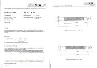
Annex A<br />
Drawings of Bierbach screws<br />
Spitze alternativ mit<br />
oder ohne Kerbschlitz<br />
BiERBACH - DaBAU-Schrauben dürfen aus härtbaren<br />
Kohlenstoffstahlstahl und Edelstahl hergestellt werden<br />
Zwischen 180mm und 600mm ist jede Länge Ln möglich<br />
mit Kerbschlitz<br />
ca. 20 mm lang<br />
A<br />
A<br />
Ø d<br />
Alternative Kopfform<br />
90°<br />
60°<br />
60°<br />
± 0,75<br />
A<br />
Detail "Y"<br />
Ø 5,0<br />
Ø 8,0<br />
1,5<br />
-0,5<br />
®<br />
BiERBACH - DaBAU- Schraube<br />
als Holzverbindungsmittel<br />
K<br />
ø dK<br />
ø 13<br />
± 0,75<br />
A<br />
2,0<br />
1,5<br />
3,0<br />
Detail "X"<br />
4<br />
Längenkennung Lk<br />
i<br />
B 011<br />
D a B AU<br />
Herstellerkennung:<br />
BiROX Nr.: 40<br />
180<br />
200<br />
225<br />
250<br />
275<br />
300<br />
325<br />
350<br />
375<br />
400<br />
420<br />
440<br />
480<br />
520<br />
560<br />
600<br />
± 0,75<br />
Ø d<br />
Anlage 1<br />
zur <strong>ETA</strong>- Zulassung<br />
vom<br />
K<br />
Bi 003<br />
Bi 004<br />
Bi 005<br />
Bi 006<br />
Bi 007<br />
Bi 008<br />
Bi 009<br />
Bi 010<br />
Bi 011<br />
Bi 0<strong>12</strong><br />
Bi 013<br />
Bi 014<br />
Bi 015<br />
Bi 016<br />
Bi 017<br />
Bi 018<br />
BiROX Nr.: 40<br />
Vertiefung<br />
BiROX Nr.: 40<br />
6 Friktionsrippen 0,6 x 45°<br />
alle 60° am Umfang verteilt<br />
Ln LK dK dK dK<br />
16<br />
16<br />
16<br />
16<br />
16<br />
16<br />
16<br />
16<br />
16<br />
16<br />
16<br />
16<br />
16<br />
16<br />
16<br />
16<br />
18<br />
18<br />
18<br />
18<br />
18<br />
18<br />
18<br />
18<br />
18<br />
18<br />
18<br />
18<br />
18<br />
18<br />
18<br />
18<br />
20<br />
20<br />
20<br />
20<br />
20<br />
20<br />
20<br />
20<br />
20<br />
20<br />
20<br />
20<br />
20<br />
20<br />
20<br />
20
<strong>ETA</strong>- Zul-0002-DaBAU-WD ø 8<br />
ln<br />
80 ≤ 100<br />
Page <strong>12</strong> of 26 of <strong>European</strong> <strong>Technical</strong> <strong>Approval</strong> no. <strong>ETA</strong>-<strong>12</strong>/<strong>0087</strong><br />
BiERBACH ® GmbH & Co. KG<br />
Befestigungstechnik<br />
Rudolf Diesel Strasse<br />
D-59425 Unna<br />
"Y"<br />
ø 5,0<br />
± 0,25<br />
ø 8,0 - 0,50<br />
4<br />
" X "<br />
50<br />
Spitze alternativ mit<br />
oder ohne Kerbschlitz<br />
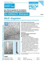
Zwischen 180mm und 600mm ist jede Länge Ln möglich<br />
mit Kerbschlitz<br />
ca. 20 mm lang<br />
A<br />
A<br />
Ø d<br />
Alternative Kopfform<br />
90°<br />
60°<br />
K<br />
ø dK<br />
ø 13<br />
BiERBACH - DaBAU-WD Schrauben dürfen aus härtbaren<br />
Kohlenstoffstahlstahl und Edelstahl hergestellt werden<br />
60°<br />
± 0,75<br />
A<br />
± 0,75<br />
A<br />
Detail "Y"<br />
Ø 5,0<br />
Ø 8,0<br />
1,5<br />
2,0<br />
1,5<br />
-0,5<br />
3,0<br />
Detail "X"<br />
4<br />
®<br />
BiERBACH - DaBAU-WD Schraube<br />
als Holzverbindungsmittel<br />
Längenkennung Lk<br />
i<br />
B 011<br />
Da B AU<br />
®<br />
Herstellerkennung:<br />
BiROX Nr.: 40<br />
180<br />
200<br />
225<br />
250<br />
275<br />
300<br />
325<br />
350<br />
375<br />
400<br />
420<br />
440<br />
480<br />
520<br />
560<br />
600<br />
± 0,75<br />
Ø d<br />
Anlage 2<br />
zur <strong>ETA</strong>- Zulassung<br />
vom<br />
K<br />
BiROX Nr.: 40<br />
Bi 003<br />
Bi 004<br />
Bi 005<br />
Bi 006<br />
Bi 007<br />
Bi 008<br />
Bi 009<br />
Bi 010<br />
Bi 011<br />
Bi 0<strong>12</strong><br />
Bi 013<br />
Bi 014<br />
Bi 015<br />
Bi 016<br />
Bi 017<br />
Bi 018<br />
BiROX Nr.: 40<br />
Kennzeichen für<br />
DaBAU-WD<br />
Vertiefung<br />
6 Friktionsrippen 0,6 x 45°<br />
alle 60° am Umfang verteilt<br />
Ln LK dK dK dK<br />
16<br />
16<br />
16<br />
16<br />
16<br />
16<br />
16<br />
16<br />
16<br />
16<br />
16<br />
16<br />
16<br />
16<br />
16<br />
16<br />
18<br />
18<br />
18<br />
18<br />
18<br />
18<br />
18<br />
18<br />
18<br />
18<br />
18<br />
18<br />
18<br />
18<br />
18<br />
18<br />
20<br />
20<br />
20<br />
20<br />
20<br />
20<br />
20<br />
20<br />
20<br />
20<br />
20<br />
20<br />
20<br />
20<br />
20<br />
20
<strong>ETA</strong>-Zul-0003-IngBau_Ø6<br />
L<br />
Page 13 of 26 of <strong>European</strong> <strong>Technical</strong> <strong>Approval</strong> no. <strong>ETA</strong>-<strong>12</strong>/<strong>0087</strong><br />
Ø 4,35 ±0,10<br />
B<br />
Lg<br />
BiERBACH ® GmbH & Co. KG<br />
Befestigungstechnik<br />
Rudolf Diesel Strasse<br />
D-59425 Unna<br />
Schraubenkopf<br />
Detail "X"<br />
Ø 6,0<br />
B<br />
"Y"<br />
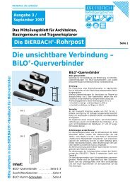
Reibgewinde<br />
Eine Schneidkerbe unter 6° bis 10°<br />
am zylindrischen Gewindeteil.<br />
Gewinde Stahl: zweigängig<br />
Gewinde Edelstahl: eingängig<br />
mit Kerbschlitz<br />
ca. 20 mm lang<br />
Spitze alternativ mit<br />
oder ohne Kerbschlitz<br />
BiERBACH - IngBAU- Schrauben dürfen aus härtbaren<br />
Kohlenstoffstahlstahl und Edelstahl hergestellt werden<br />
Ø 14/Ø16/Ø18<br />
40°<br />
ø <strong>12</strong> / ø 14<br />
Schnitt B-B<br />
Ø 5,6<br />
60°<br />
®<br />
BiRA - IngBAU - Schraube Ø 6,0<br />
als Holzverbindungsmittel<br />
BiROX Nr.:30<br />
Herstellerkennzeichen<br />
Alternative Kopfformen<br />
Detail "Y"<br />
zweigängig<br />
Ø 3,90<br />
Ø 6,0<br />
Schraubenkopf Detail "X"<br />
0<br />
I<br />
6 /<br />
n<br />
X<br />
g<br />
X<br />
L Lg Lk<br />
Anlage 3<br />
zur <strong>ETA</strong>- Zulassung<br />
vom<br />
B<br />
X<br />
24 alternativ 6 Friktionsrippen<br />
gleichmäßig am Umfang verteilt<br />
5,0<br />
Detail "Y"<br />
eingängig<br />
Ø 3,90<br />
Ø 6,0<br />
2,6<br />
ø <strong>12</strong> / ø 14<br />
90°<br />
60<br />
70<br />
80<br />
90<br />
100<br />
<strong>12</strong>0<br />
130<br />
140<br />
150<br />
160<br />
180<br />
200<br />
220<br />
240<br />
260<br />
280<br />
300<br />
A<br />
U<br />
Längenkennzeichnung Lk<br />
Sechskant + BiROX<br />
Ø10/Ø<strong>12</strong><br />
Schneidkerbe<br />
90°<br />
40<br />
40<br />
40<br />
50<br />
50<br />
50<br />
50<br />
50<br />
50<br />
50<br />
50<br />
50<br />
50<br />
50<br />
50<br />
50<br />
50<br />
~1,0<br />
06/060<br />
06/070<br />
06/080<br />
06/090<br />
06/100<br />
06/<strong>12</strong>0<br />
06/130<br />
06/140<br />
06/150<br />
06/160<br />
06/180<br />
06/200<br />
06/220<br />
06/240<br />
06/260<br />
06/280<br />
06/300
<strong>ETA</strong>-Zul-0004 IngBAU-Ø8<br />
L<br />
Page 14 of 26 of <strong>European</strong> <strong>Technical</strong> <strong>Approval</strong> no. <strong>ETA</strong>-<strong>12</strong>/<strong>0087</strong><br />
Lg<br />
BiERBACH ® GmbH & Co. KG<br />
® BiRA - IngBAU - Schraube Ø 8,0<br />
Befestigungstechnik<br />
Rudolf Diesel Strasse<br />
als Holzverbindungsmittel<br />
D-59425 Unna<br />
B<br />
"Y"<br />
Schraubenkopf<br />
Detail "X"<br />
Ø 6,0<br />
B<br />
Ø 8,0<br />
± 0,35<br />
Reibgewinde<br />
Eine Schneidkerbe unter 6° bis 10°<br />
am zylindrischen Gewindeteil.<br />
Gewinde: eingängig<br />
Spitze alternativ mit<br />
oder ohne Kerbschlitz<br />
mit Kerbschlitz<br />
ca. 20 mm lang<br />
BiERBACH - IngBAU- Schrauben dürfen aus härtbaren<br />
Kohlenstoffstahlstahl und Edelstahl hergestellt werden<br />
40°<br />
Ø16 / Ø18 / Ø20<br />
Ø16 / Ø18 / Ø20<br />
BiROX Nr.:40<br />
Herstellerkennzeichen<br />
Alternative Kopfformen<br />
Schnitt B-B<br />
Ø 7,0<br />
60°<br />
ø 5,0<br />
Detail "Y"<br />
Ø 5,0<br />
Ø 8,0<br />
Schraubenkopf Detail "X"<br />
4,0<br />
* ohne Reibgewinde<br />
I<br />
08 /<br />
n<br />
X<br />
g<br />
X<br />
B<br />
X<br />
6 Friktionsrippen gleichmäßig<br />
am Umfang verteilt<br />
Ø16 / Ø18 / Ø20<br />
90°<br />
Anlage 4<br />
zur <strong>ETA</strong>- Zulassung<br />
vom<br />
A<br />
U<br />
90°<br />
Längenkennzeichnung Lk<br />
Schneidkerbe<br />
80 *<br />
100 *<br />
<strong>12</strong>0 *<br />
140<br />
160<br />
180<br />
200<br />
220<br />
240<br />
260<br />
280<br />
300<br />
320<br />
340<br />
360<br />
380<br />
400<br />
420<br />
440<br />
Sechskant + BiROX Nr.:30<br />
Ø15 / Ø17<br />
70<br />
80<br />
80<br />
80 / 100<br />
80 / 100<br />
80 / 100<br />
80 / 100<br />
80 / 100<br />
80 / 100<br />
80 / 100<br />
80 / 100<br />
80 / 100<br />
80 / 100<br />
80 / 100<br />
80 / 100<br />
80 / 100<br />
80 / 100<br />
80 / 100<br />
80 / 100<br />
~1,0<br />
L Lg Lk<br />
08/080<br />
08/100<br />
08/<strong>12</strong>0<br />
08/140<br />
08/160<br />
08/180<br />
08/200<br />
08/220<br />
08/240<br />
08/260<br />
08/280<br />
08/300<br />
08/320<br />
08/340<br />
08/360<br />
08/380<br />
08/400<br />
08/420<br />
08/440
<strong>ETA</strong>-Zul-0005 IngBAU-Ø10<br />
L<br />
Page 15 of 26 of <strong>European</strong> <strong>Technical</strong> <strong>Approval</strong> no. <strong>ETA</strong>-<strong>12</strong>/<strong>0087</strong><br />
Lg<br />
BiERBACH ® GmbH & Co. KG<br />
® BiRA - IngBAU - Schraube Ø 10,0<br />
Befestigungstechnik<br />
Rudolf Diesel Strasse<br />
als Holzverbindungsmittel<br />
D-59425 Unna<br />
B<br />
"Y"<br />
± 0,30<br />
Ø 6,8<br />
B<br />
Schraubenkopf<br />
Detail "X"<br />
Reibgewinde<br />
Eine Schneidkerbe unter 6° bis 10°<br />
am zylindrischen Gewindeteil.<br />
Gewinde: eingängig<br />
Spitze alternativ mit<br />
oder ohne Kerbschlitz<br />
Ø 10,0<br />
BiERBACH - IngBAU-Schrauben werden aus<br />
härtbaren Kohlenstoffstahlstahl hergestellt<br />
40°<br />
mit Kerbschlitz<br />
ca. 20 mm lang<br />
6 Friktionsrippen gleichmäßig<br />
am Umfang verteilt.<br />
ø18 / ø20 / ø22<br />
90°<br />
Schnitt B-B<br />
Ø 9,0<br />
60°<br />
Schraubenkopf Detail "X"<br />
ø18 / ø20 / ø22<br />
Detail "Y"<br />
Ø 6,0<br />
Ø 10<br />
1,3<br />
BiROX Nr.:40<br />
Herstellerkennzeichen<br />
Alternative Kopfformen<br />
ø 6,0<br />
4,5<br />
* ohne Reibgewinde<br />
I<br />
10 /<br />
n<br />
X<br />
g<br />
X<br />
B<br />
X<br />
A<br />
Anlage 5<br />
zur <strong>ETA</strong>- Zulassung<br />
vom<br />
U<br />
Längenkennzeichnung Lk<br />
SW 15 + BiROX Nr.:40<br />
Ø17,5<br />
Schneidkerbe<br />
100 *<br />
<strong>12</strong>0 *<br />
140<br />
160<br />
180<br />
200<br />
220<br />
240<br />
260<br />
280<br />
300<br />
320<br />
340<br />
360<br />
380<br />
400<br />
420<br />
440<br />
90°<br />
~1,0<br />
80<br />
80<br />
80<br />
100 / <strong>12</strong>0<br />
100 / <strong>12</strong>0<br />
100 / <strong>12</strong>0<br />
100 / <strong>12</strong>0<br />
100 / <strong>12</strong>0<br />
100 / <strong>12</strong>0<br />
100 / <strong>12</strong>0<br />
100 / <strong>12</strong>0<br />
100 / <strong>12</strong>0<br />
100 / <strong>12</strong>0<br />
100 / <strong>12</strong>0<br />
100 / <strong>12</strong>0<br />
100 / <strong>12</strong>0<br />
100 / <strong>12</strong>0<br />
100 / <strong>12</strong>0<br />
4,20<br />
L Lg Lk<br />
10/100<br />
10/<strong>12</strong>0<br />
10/140<br />
10/160<br />
10/180<br />
10/200<br />
10/220<br />
10/240<br />
10/260<br />
10/280<br />
10/300<br />
10/320<br />
10/340<br />
10/360<br />
10/380<br />
10/400<br />
10/420<br />
10/440
Page 16 of 26 of <strong>European</strong> <strong>Technical</strong> <strong>Approval</strong> no. <strong>ETA</strong>-<strong>12</strong>/<strong>0087</strong><br />
Bierbach Washers
Page 17 of 26 of <strong>European</strong> <strong>Technical</strong> <strong>Approval</strong> no. <strong>ETA</strong>-<strong>12</strong>/<strong>0087</strong>
Page 18 of 26 of <strong>European</strong> <strong>Technical</strong> <strong>Approval</strong> no. <strong>ETA</strong>-<strong>12</strong>/<strong>0087</strong>
Page 19 of 26 of <strong>European</strong> <strong>Technical</strong> <strong>Approval</strong> no. <strong>ETA</strong>-<strong>12</strong>/<strong>0087</strong><br />
Annex B<br />
Minimum distances and spacing<br />
Axially or laterally loaded screws in the plane or edge surface of cross laminated timber<br />
Definition of spacing, end and edge distances in the plane surface unless otherwise specified in the technical<br />
specification (<strong>ETA</strong> or hEN) for the cross laminated timber:<br />
a1,t<br />
a1<br />
α<br />
F<br />
α<br />
F<br />
a2<br />
a1,c<br />
a2,c<br />
a2<br />
a2<br />
α a2,t<br />
F<br />
Definition of spacing, end and edge distances in the edge surface unless otherwise specified in the technical<br />
specification (<strong>ETA</strong> or hEN) for the cross laminated timber:<br />
a 1,c<br />
a 1<br />
a 1,t<br />
F<br />
t CLT<br />
t i<br />
a 2,c<br />
a2,c<br />
a 1,c<br />
a 1<br />
a 1,c<br />
F<br />
t CLT<br />
t i<br />
a 2,c<br />
a2,t<br />
F
Page 20 of 26 of <strong>European</strong> <strong>Technical</strong> <strong>Approval</strong> no. <strong>ETA</strong>-<strong>12</strong>/<strong>0087</strong><br />
Annex C<br />
Thermal insulation material on top of rafters or facades<br />
Bierbach DaBau and DaBau WD are exclusively, IngBau screws may be used for the fixing of heat<br />
insulation on top of rafters.<br />
The thickness of the insulation shall not exceed 400 mm. The rafter insulation must be placed on top of solid<br />
timber or glued laminated timber rafters or cross-laminated timber members and be fixed by battens<br />
arranged parallel to the rafters or by wood-based panels on top of the insulation layer. The insulation of<br />
vertical facades is also covered by the rules given here.<br />
Screws must be screwed in the rafter through the battens or panels and the insulation without pre-drilling in<br />
one sequence.<br />
The angle α between the screw axis and the grain direction of the rafter should be between 30° and 90°.<br />
The rafter consists of solid timber (softwood) according to EN 338, glued laminated timber according to EN<br />
14081, cross-laminated timber, or laminated veneer lumber according to EN 14374 or to <strong>European</strong><br />
<strong>Technical</strong> <strong>Approval</strong> or similar glued members according to <strong>European</strong> <strong>Technical</strong> <strong>Approval</strong>.<br />
The battens must be from solid timber (softwood) according to EN 338:2003-04. The minimum thickness t<br />
and the minimum width b of the battens is given as follows:<br />
Screws d ≤ 8,0 mm: bmin = 50 mm tmin = 30 mm<br />
Screws d = 10 mm: bmin = 60 mm tmin = 40 mm<br />
The insulation must comply with a <strong>European</strong> <strong>Technical</strong> <strong>Approval</strong>.<br />
Friction forces shall not be considered for the design of the characteristic axial capacity of the screws.<br />
The anchorage of wind suction forces as well as the bending stresses of the battens or the boards,<br />
respectively, shall be considered in design. Additional screws perpendicular to the grain of the rafter (angle<br />
α = 90°) may be arranged if necessary.<br />
The maximum screw spacing is eS = 1,75 m.
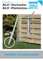
Mechanical model<br />
Page 21 of 26 of <strong>European</strong> <strong>Technical</strong> <strong>Approval</strong> no. <strong>ETA</strong>-<strong>12</strong>/<strong>0087</strong><br />
Heat insulation on rafters with parallel inclined screws<br />
The system of rafter, heat insulation on top of rafter and battens parallel to the rafter may be considered<br />
as a beam on elastic foundation. The batten represents the beam, and the heat insulation on top of the<br />
rafter the elastic foundation. The minimum compression stress of the heat insulation at 10 %<br />
deformation, measured according to EN 8262, shall be σ(10 %) = 0,05 N/mm². The batten is loaded<br />
perpendicular to the axis by point loads Fb. Further point loads Fs are from the shear load of the roof due<br />
to dead and snow load, which are transferred from the screw heads into the battens.<br />
α<br />
e scr<br />
lef<br />
e scr e scr<br />
ß<br />
dead load and<br />
snow load s0<br />
wind<br />
wpressure<br />
screw axis<br />
tensile force Fz<br />
concentrated compression load<br />
in heat insulation<br />
ß<br />
wsuction<br />
compression in<br />
heat insulation<br />
axis<br />
batten<br />
top edge rafter<br />
α = angle between screw axis and rafter axis<br />
β = roof pitch<br />
escr = screws distance<br />
lef = penetration length in the rafter<br />
batten<br />
heat insulation<br />
vapor barrier<br />
roof boarding<br />
2 EN 826:1996 Thermal insulating products for building applications - Determination of compression<br />
behaviour<br />
α<br />
rafter
Design of the battens<br />
Page 22 of 26 of <strong>European</strong> <strong>Technical</strong> <strong>Approval</strong> no. <strong>ETA</strong>-<strong>12</strong>/<strong>0087</strong><br />
The bending stresses are calculated as:<br />
(F + F ) ⋅l<br />
M =<br />
4<br />
Where<br />
b s char<br />
lchar = characteristic length char<br />
4<br />
l<br />
=<br />
4 ⋅ EI<br />
w ⋅ K<br />
EI = bending stiffness of the batten<br />
K = coefficient of subgrade<br />
wef = effective width of the heat insulation<br />
Fb = Point loads perpendicular to the battens<br />
ef<br />
Fs = Point loads perpendicular to the battens, load application in the area of the screw heads<br />
The coefficient of subgrade K may be calculated from the modulus of elasticity EHI and the thickness tHI of<br />
the heat insulation if the effective width wef of the heat insulation under compression is known. Due to the<br />
load extension in the heat insulation the effective width wef is greater than the width of the batten or rafter,<br />
respectively. For further calculations, the effective width wef of the heat insulation may be determined<br />
according to:<br />
wef = w + t HI / 2<br />
where<br />
w = minimum width of the batten or rafter, respectively<br />
tHI = thickness of the heat insulation<br />
EHI<br />
K =<br />
t<br />
HI<br />
The following condition shall be satisfied:<br />
σm,d<br />
Md<br />
= ≤1<br />
f W ⋅ f<br />
m,d m,d<br />
For the calculation of the section modulus W the net cross section has to be considered.<br />
The shear stresses shall be calculated according to:<br />
(Fb + F s)<br />
V =<br />
2<br />
The following condition shall be satisfied:<br />
τd 1,5 ⋅ Vd = ≤1<br />
f A ⋅f<br />
v,d v,d<br />
For the calculation of the cross section area the net cross section has to be considered.<br />
Design of the heat insulation<br />
The compressive stresses in the heat insulation shall be calculated according to:<br />
1,5 ⋅ Fb + Fs<br />
σ =<br />
2 ⋅ l ⋅ w<br />
char<br />
The design value of the compressive stress shall not be greater than 110 % of the compressive stress at<br />
10 % deformation calculated according to EN 826.<br />
Design of the screws<br />
The screws are loaded predominantly axially. The axial tension force in the screw may be calculated<br />
from the shear loads of the roof Rs:<br />
RS<br />
TS<br />
=<br />
cosα
Page 23 of 26 of <strong>European</strong> <strong>Technical</strong> <strong>Approval</strong> no. <strong>ETA</strong>-<strong>12</strong>/<strong>0087</strong><br />
The load-carrying capacity of axially loaded screws is the minimum design value of the axial withdrawal<br />
capacity of the threaded part of the screw, the head pull-through capacity of the screw and the tensile<br />
capacity of the screw.<br />
In order to limit the deformation of the screw head for heat insulation thicknesses over 200 mm or with<br />
compressive strength below 0,<strong>12</strong> N/mm², respectively, the axial withdrawal capacity of the screws shall be<br />
reduced by the factors k1 and k2:<br />
0.8 0.8<br />
⎧⎪ fax,d ⋅d ⋅l ef ⋅ k1 ⋅ k2 ⎛ ρk ⎞ 2 ⎛ ρ f k ⎞ ⎫ tens,k ⎪<br />
Fax, α,Rd<br />
= min ⎨ ⋅⎜ ⎟ ;f head,d ⋅d h ⋅⎜<br />
⎟ ; ⎬ for DaBau and IngBau screws<br />
⎪⎩ 1.2⋅ cos² α + sin ² α ⎝ 350 ⎠ ⎝ 350 ⎠ γM2<br />
⎪⎭<br />
0,8<br />
⎧ fax,d ⋅d ⋅ lef<br />
⋅ k1 ⋅ k<br />
⎫<br />
2 ⎛ ρk<br />
⎞<br />
⎪ ⋅<br />
2 2 ⎜ ⎟ ⎪<br />
⎪ 1,2 ⋅cos α + sin α ⎝ 350 ⎠ ⎪<br />
⎪ 0,8<br />
⎪ ⎧ 2 fax,d ⋅d ⋅l<br />
ef ,b ⎫<br />
⎪<br />
F = min<br />
⎛ ρk<br />
⎞ ⎪<br />
ax , α ,Rd ⎨max ⎨fhead,d ⋅d h; ⋅<br />
2 2 ⎬ ⎜ ⎟ ⎬<br />
where:<br />
fax,d<br />
⎪ ⎩ 1,2 ⋅cos α + sin α ⎭ ⎝ 350 ⎠ ⎪<br />
⎪f ⎪<br />
tens,k ⎪ ⎪<br />
⎪⎩ γM2<br />
⎪⎭<br />
for DaBau WD screws<br />
design value of the axial withdrawal parameter of the threaded part of the screw in the rafter<br />
or batten, fax,d does not apply for wood-based panels except plywood, LVL or cross-laminated<br />
timber/solid wood panels<br />
d outer thread diameter of the screw<br />
lef<br />
lef,b<br />
Point side penetration length of the threaded part of the screw in the batten, lef ≥ 40 mm<br />
Length of the threaded part in the batten including the head for tensile and excluding the head<br />
for compressive force [mm]<br />
α Angle between grain and screw axis (α > 30°)<br />
ρk<br />
fhead,d<br />
dh<br />
ftens,k<br />
γM2<br />
k1<br />
k2<br />
tHI<br />
σ 10%<br />
characteristic density of the wood-based member [kg/m³]<br />
design value of the head pull-through capacity of the screw<br />
head diameter<br />
characteristic tensile capacity of the screw<br />
partial factor according to EN 1993-1-1 or to the particular national annex<br />
min {1; 220/tHI}<br />
min {1; σ10%/0,<strong>12</strong>}<br />
thickness of the heat insulation [mm]<br />
compressive stress of the heat insulation under 10 % deformation [N/mm²]<br />
If equation k1 and k2 are considered, the deflection of the battens does not need to be considered.<br />
Alternatively to the battens, panels with a minimum thickness of 22 mm from plywood according to EN 636<br />
or an <strong>ETA</strong> or national provisions that apply at the installation site, particle board according to EN 3<strong>12</strong> or an<br />
<strong>ETA</strong> or national provisions that apply at the installation site, oriented strand board according to EN 300 or<br />
an <strong>ETA</strong> or national provisions that apply at the installation site and solid wood panels according to EN<br />
13353 or an <strong>ETA</strong> or national provisions that apply at the installation site or cross laminated timber<br />
according to an <strong>ETA</strong> may be used.
Page 24 of 26 of <strong>European</strong> <strong>Technical</strong> <strong>Approval</strong> no. <strong>ETA</strong>-<strong>12</strong>/<strong>0087</strong><br />
B<br />
l ef,b<br />
Heat insulation on rafters with alternatively inclined screws<br />
A<br />
ß<br />
1 2<br />
6<br />
5<br />
l ef,r 90° - = 0° to 60°<br />
α 1<br />
α 2<br />
4<br />
3<br />
90° - = 0° to 60°<br />
H<br />
1 counter batten<br />
2 insulation<br />
3 vapour barrier<br />
4 sheating<br />
5 compressive screw<br />
6 rafter<br />
Mechanical model<br />
Depending on the screw spacing and the arrangement of tensile and compressive screws with different<br />
inclinations the battens are loaded by significant bending moments. The bending moments are derived<br />
based on the following assumptions:<br />
• The tensile and compressive loads in the screws are determined based on equilibrium conditions<br />
from the actions parallel and perpendicular to the roof plane.<br />
These actions are constant line loads q⊥ and q ⎢⎢.<br />
• The screws act as hinged columns supported 10 mm within the batten or rafter, respectively. The<br />
effective column length consequently equals the length of the screw between batten and rafter plus<br />
20 mm.<br />
• The batten is considered as a continuous beam with a constant span l = A + B.<br />
The compressive screws constitute the supports of the continuous beam while the tensile screws<br />
transfer concentrated loads perpendicular to the batten axis.<br />
The screws are predominantly loaded in withdrawal or compression, respectively. The screw’s normal<br />
forces are determined based on the loads parallel and perpendicular to the roof plane:<br />
Compressive screw:<br />
Tensile screw:<br />
⎛ qII ⋅sin α 2 + q⊥ ⋅cos α ⎞ 2<br />
F c,Ed = (A + B) ⋅⎜ −<br />
⎟<br />
sin<br />
( α + α )<br />
⎝ 1 2 ⎠<br />
⎛ qII ⋅sin α1 − q⊥ ⋅cos α ⎞ 1<br />
F t,Ed = (A + B) ⋅⎜ ⎟<br />
⎝ sin ( α 1 + α2<br />
) ⎠<br />
Counter batten
Page 25 of 26 of <strong>European</strong> <strong>Technical</strong> <strong>Approval</strong> no. <strong>ETA</strong>-<strong>12</strong>/<strong>0087</strong><br />
The bending moments in the batten follow from the constant line load q⊥ and the load components<br />
perpendicular to the batten from the tensile screws. The span of the continuous beam is (A + B). The<br />
load component perpendicular to the batten from the tensile screw is:<br />
⎛ qII ⋅sin α1 ⋅sin α2 − q⊥ ⋅cos α1 ⋅sin α2<br />
⎞<br />
F ZS,Ed = (A + B) ⋅⎜ ⎟<br />
⎝ sin( α 1 + α2<br />
) ⎠<br />
Where:<br />
qII Constant line load parallel to batten<br />
q⊥ Constant line load perpendicular to batten<br />
α1 Angle between compressive screw axis and grain direction<br />
Angle between tensile screw axis and grain direction<br />
α2<br />
A positive value for FZS means a load towards the rafter, a negative value a load away from the rafter.<br />
Design of the screws<br />
The load-carrying capacity of the screws shall be calculated as follows:<br />
Screws loaded in tension:<br />
0.8 0.8<br />
⎧<br />
⎪ fax,d ⋅ d ⋅ lef ,b ⎛ ρb,k ⎞ fax,d ⋅d ⋅ lef<br />
,r ⎛ ρr,k<br />
⎞ f ⎫<br />
tens,k ⎪<br />
Fax, α,Rd<br />
= min ⎨ ⋅⎜ ⎟ ; ⋅⎜<br />
⎟ ; ⎬<br />
⎪1.2 ⋅cos² α + sin ² α ⎝ 350 ⎠ 1.2 ⋅cos ² α + sin ² α ⎝ 350 ⎠ γ<br />
⎩ M2 ⎪⎭<br />
Screws loaded in compression:<br />
0.8 0.8<br />
⎧<br />
⎪ fax,d ⋅d ⋅l ef ,b ⎛ ρb,k ⎞ fax,d ⋅ d ⋅ lef<br />
,r ⎛ ρr,k<br />
⎞ κc ⋅ N ⎫<br />
pl,k ⎪<br />
Fax, α,Rd<br />
= min ⎨ ⋅⎜ ⎟ ; ⋅⎜<br />
⎟ ; ⎬<br />
⎪1.2 ⋅cos² α + sin ² α ⎝ 350 ⎠ 1.2⋅ cos² α + sin ² α ⎝ 350 ⎠ γ<br />
⎩ M1 ⎪⎭<br />
where:<br />
fax,d<br />
design value of the axial withdrawal parameter of the threaded part of the screw in the rafter<br />
or batten, fax,d does not apply for wood-based panels except plywood, LVL or crosslaminated<br />
timber/solid wood panels<br />
d outer thread diameter of the screw<br />
lef,b<br />
lef,r<br />
ρb�k<br />
ρr�k<br />
penetration length of the threaded part of the screw in the batten<br />
penetration length of the threaded part of the screw in the rafter, lef ≥ 40 mm<br />
characteristic density of the batten [kg/m³]<br />
characteristic density of the rafter [kg/m³]<br />
α angle α1 or α2 between screw axis and grain direction, 30° ≤ α� ≤ 90°, 30° ≤ α2 ≤ 90°<br />
ftens,k<br />
γM1, γM2<br />
κc · Npl,k<br />
characteristic tensile capacity of the screw<br />
partial factor according to EN 1993-1-1 or to the particular national annex<br />
Buckling capacity of the screw
Free screw<br />
length [mm]<br />
Page 26 of 26 of <strong>European</strong> <strong>Technical</strong> <strong>Approval</strong> no. <strong>ETA</strong>-<strong>12</strong>/<strong>0087</strong><br />
DaBau WD<br />
κc · Npl,k [kN]<br />
≤ 100 5,72<br />
<strong>12</strong>0 4,39<br />
140 3,46<br />
160 2,80<br />
180 2,32<br />
200 1,94<br />
220 1,65<br />
240 1,42<br />
260 1,23<br />
280 1,08<br />
300 0,95<br />
320 0,85<br />
340 0,76<br />
360 0,69<br />
380 0,62<br />
400 0,57<br />
420 0,52<br />
440 0,47<br />
460 0,44<br />
480 0,40