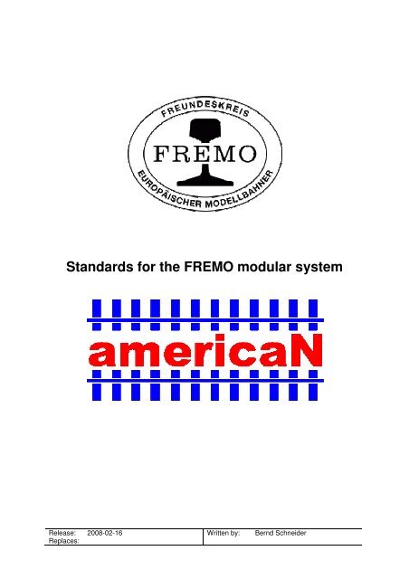
Standards for the FREMO modular system
Standards for the FREMO modular system
Standards for the FREMO modular system

You also want an ePaper? Increase the reach of your titles
YUMPU automatically turns print PDFs into web optimized ePapers that Google loves.
<strong>Standards</strong> <strong>for</strong> <strong>the</strong> <strong>FREMO</strong> <strong>modular</strong> <strong>system</strong><br />
Release: 2008-02-16<br />
Replaces:<br />
Written by: Bernd Schneider
<strong>FREMO</strong> americaN<br />
www.america-n.de<br />
Contents<br />
Page 2 of 11<br />
1 Preface and Introduction .................................................................................................... 3<br />
2 Notes on this version.......................................................................................................... 3<br />
3 Module structure ................................................................................................................ 3<br />
3.1 Geometry of module structure.................................................................................... 3<br />
3.2 End profile.................................................................................................................. 4<br />
3.3 Height of rail top ........................................................................................................ 4<br />
3.4 Module connection..................................................................................................... 4<br />
3.5 Color of side panels.................................................................................................... 5<br />
4 Track................................................................................................................................... 5<br />
4.1 Allowed track material ............................................................................................... 5<br />
4.2 Minimum radius ......................................................................................................... 5<br />
4.3 Clearances and track axis distances ........................................................................... 5<br />
4.4 Uncoupling magnets................................................................................................... 5<br />
4.5 Throw mechanisms and controls................................................................................ 6<br />
5 Rolling stock ...................................................................................................................... 6<br />
5.1 Wheelsets ................................................................................................................... 6<br />
5.2 Couplers ..................................................................................................................... 6<br />
5.3 Car weight .................................................................................................................. 6<br />
5.4 Motive power ............................................................................................................. 6<br />
5.5 Wea<strong>the</strong>ring ................................................................................................................. 6<br />
6 Landscape........................................................................................................................... 6<br />
6.1 Season, era and modeled region................................................................................. 6<br />
6.2 Grass fiber / landscaping material.............................................................................. 7<br />
6.3 Color of track and ballast ........................................................................................... 7<br />
6.4 Telephone poles.......................................................................................................... 7<br />
7 Electrical equipment........................................................................................................... 8<br />
7.1 Electrical connection to track work............................................................................ 8<br />
7.2 Electrical connection between modules ..................................................................... 8<br />
7.3 DCC booster............................................................................................................... 8<br />
7.4 LocoNet...................................................................................................................... 8<br />
8 Car cards............................................................................................................................. 8<br />
9 Datasheet & waybills ......................................................................................................... 9<br />
9.1 General ....................................................................................................................... 9<br />
9.2 9.2 Datasheet and car cards........................................................................................ 9<br />
9.3 Car card boxes at stations......................................................................................... 11<br />
10 Recommended materials .............................................................................................. 11<br />
11 Links............................................................................................................................. 11<br />
12 Contact ......................................................................................................................... 11
<strong>FREMO</strong> americaN<br />
www.america-n.de<br />
1 Preface and Introduction<br />
Page 3 of 11<br />
americaN is a module standard adopted by <strong>the</strong> <strong>FREMO</strong> (Friendscircle of European<br />
Modelrailroaders). Modules build to this standard resemble single-track standard gauge<br />
railroad lines in North America in N-scale (1:160). There are no restrictions on ei<strong>the</strong>r area or<br />
era.<br />
This document contains standards as well as recommended practices <strong>for</strong> building and<br />
detailing americaN modules. There are also standards <strong>for</strong> materials necessary <strong>for</strong> prototypeoriented<br />
operations, <strong>for</strong> example car cards and waybills. Important aspects of <strong>the</strong> “Track<br />
Warrant Control” operations (which is our preferred method) are described in a separate short<br />
reference. This document can be loaded from <strong>the</strong> homepage of americaN.<br />
The americaN module <strong>system</strong> was developed in 2001 because <strong>the</strong> initiators felt that <strong>the</strong><br />
already existing module <strong>system</strong>s, NTRAK and oneTRAK no longer reflected <strong>the</strong> current<br />
philosophy of <strong>modular</strong> model railroading. In <strong>the</strong> americaN <strong>system</strong> <strong>the</strong> use of a prototypical<br />
traffic control <strong>system</strong>, as well as simulation of traffic flow with car cards and waybills, is very<br />
important. This overall concept already existed with <strong>FREMO</strong> module <strong>system</strong>s. For <strong>the</strong><br />
americaN standard, many ideas were taken from <strong>FREMO</strong> H0(USA) and fremo-N. One o<strong>the</strong>r<br />
important aspect of americaN is <strong>the</strong> use of commercial track and turnouts.<br />
The main characteristics of americaN are:<br />
- free module geometry,<br />
- height of rail top above ground 1300 mm,<br />
- use of NMRA-DCC and LocoNet,<br />
- prototype-oriented operations (Track Warrant Control)<br />
- use of car cards and waybills.<br />
2 Notes on this version<br />
This is <strong>the</strong> first release of <strong>the</strong> americaN standard in <strong>the</strong> English language. It is a translation of<br />
<strong>the</strong> 2007-11-01 German standard. Modules built to preceding standards are allowed to be<br />
used, even if <strong>the</strong>y do not currently follow <strong>the</strong> norm in all details.<br />
Changes in this version are:<br />
- additional remarks on end profiles<br />
- definition of a standard <strong>for</strong> electrostatic grass and landscape<br />
- revision of waybills, now with day of week indication<br />
3 Module structure<br />
3.1 Geometry of module structure<br />
Length, width and angle of a module can be freely chosen, as long as <strong>the</strong> minimum radius of<br />
1000mm on <strong>the</strong> main track is maintained. With respect to transportability, <strong>the</strong> length of a<br />
single segment should be kept below 1200 mm.
<strong>FREMO</strong> americaN<br />
www.america-n.de<br />
3.2 End profile<br />
Image 1<br />
Page 4 of 11<br />
The underlined items are identical to <strong>the</strong> dimensions of <strong>the</strong> <strong>FREMO</strong> end profile N90, so<br />
mechanical compatibility to o<strong>the</strong>r <strong>FREMO</strong> <strong>system</strong>s in N scale is maintained. The values in<br />
brackets refer to wide-spread, commercially available products.<br />
NOTE: The 8-mm holes are NOT vertically centered! It is suggested to drill <strong>the</strong>se holes only<br />
after track has been laid. A self-made cardboard template may be very useful.<br />
3.3 Height of rail top<br />
The rail top is at a height of 1300 mm above floor. The module legs must have <strong>the</strong> possibility<br />
to adjust height <strong>for</strong> +/-20 mm. Modules with a length of 500 mm and longer must be able to<br />
stand by <strong>the</strong>mselves.<br />
3.4 Module connection<br />
The modules are mechanically connected with nuts, bolts (both M6 or 1/4") and appropriate<br />
washers. It must be possible to tighten <strong>the</strong> screws and nuts without tools, so its mandatory to<br />
use ei<strong>the</strong>r wing screws, thumb screws or eye bolts and wing nuts. Rail joiners or connecting<br />
tracks are not used. The rails end flush or with a set back up to 0,2 mm at a RIGHT ANGLE<br />
to <strong>the</strong> end plate. For improved mechanical stability <strong>the</strong> rails must be soldered to brass screws<br />
or PCB ties at <strong>the</strong> end of <strong>the</strong> module. It is important to check <strong>the</strong> gauge after completion! The<br />
railheads are to be chamfered at <strong>the</strong> module ends (see image 2).<br />
Rails must not run over <strong>the</strong> complete length of a module. For humidity compensation, a cut<br />
through both rails in <strong>the</strong> middle of <strong>the</strong> module is mandatory.
<strong>FREMO</strong> americaN<br />
www.america-n.de<br />
Image 2<br />
Page 5 of 11<br />
3.5 Color of side panels<br />
The side panels must be painted in a semi-gloss, beige color RAL 1001 Beige or equivalent.<br />
4 Track<br />
4.1 Allowed track material<br />
The maximum allowed height of <strong>the</strong> visible rail is 1,4 mm, which is Code 55. At <strong>the</strong> moment<br />
<strong>the</strong>re are two optically satisfying products resembling North American trackwork:<br />
- Atlas Code 55<br />
- Micro Engineering Code 55<br />
The Micro Engineering Code 55 flex track has <strong>the</strong> advantage that MT wheelsets with high<br />
flanges can run on it without hopping. Thus, <strong>for</strong> modules without turnouts this track is <strong>the</strong><br />
best we can recommend. All o<strong>the</strong>r trackwork should be made of Atlas Code 55 flex track and<br />
#7 turnouts or greater. Atlas turnouts are “DCC-friendly” without modifications. The frog of<br />
<strong>the</strong> #5 Atlas turnout is problematic, and requires work in order to be con<strong>for</strong>m to NMRA<br />
standard S-3.2 (Trackwork, Standard Scales).<br />
Peco Streamline Code 55 track and turnouts can also be used. Turnouts must be modified that<br />
<strong>the</strong> frog has its own current supply and is not supplied through <strong>the</strong> points exclusively.<br />
Custom-made trackwork is also acceptable if it con<strong>for</strong>ms to NMRA standard S-3.2. For<br />
compatibility with MT wheelsets, flange clearance H must be at least 0.8 mm.<br />
4.2 Minimum radius<br />
Main track curves must be built with a minimum radius of 1000 mm.<br />
4.3 Clearances and track axis distances<br />
Clearances must be con<strong>for</strong>m to NMRA standard S-7, and S-8 (using Class 1a rolling stock).<br />
4.4 Uncoupling magnets<br />
Uncoupling magnets are not allowed due to <strong>the</strong> possibility of unintended train separation. For<br />
Uncoupling, <strong>the</strong> Rix Pick N scale uncoupling tool or a similar device is used.
<strong>FREMO</strong> americaN<br />
www.america-n.de<br />
Page 6 of 11<br />
4.5 Throw mechanisms and controls<br />
A location must be easily operable <strong>for</strong> crews unfamiliar with <strong>the</strong> “territory.” Thus, turnout<br />
controls (mechanical or electrical) should be close to <strong>the</strong> turnout. Switching locations in<br />
curves, as well as junctions, must be operable from both sides of <strong>the</strong> module. Mechanical<br />
<strong>system</strong>s are especially well suited <strong>for</strong> this.<br />
Being able to operate from both sides of <strong>the</strong> module is very helpful in planning <strong>for</strong> successful<br />
arrangement of modules.<br />
5 Rolling stock<br />
5.1 Wheelsets<br />
The wheelsets must be able to roll over Atlas Code 55 turnouts and flex track without<br />
touching <strong>the</strong> rail spikes.<br />
5.2 Couplers<br />
MicroTrains or compatible couplers which can easily be opened with <strong>the</strong> Rix Picks are<br />
mandatory. Kato or older Accumate couplers do not work properly!<br />
As uncoupling magnets are not allowed, it is not necessary to adjust <strong>the</strong> trip pins. In unit train<br />
cars (passenger or freight) <strong>the</strong> couplers can be chosen freely. It is recommended practice to<br />
mount <strong>the</strong> couplers on <strong>the</strong> car body instead of on <strong>the</strong> trucks, as it provides smoo<strong>the</strong>r operation.<br />
5.3 Car weight<br />
Car weight must follow NMRA Recommended Practice RP-20.1: Initial weight 1/2 oz. + 0.15<br />
oz/inch of car body length. This equals 14g inital weight plus 1.7g per cm car body length.<br />
5.4 Motive power<br />
As americaN layouts are operated with NMRA-DCC, all motive power must be suited with an<br />
appropriate decoder. The speed curve must be adjusted in a way that maximum speed with<br />
cars on level track is approximately 60 mph (with reference to 14V track voltage, see 7.3).<br />
The half-way throttle position should be represented with about half of maximum speed.<br />
Acceleration and deceleration delay are to be switched off (CV3 and CV4), unless <strong>the</strong>y can be<br />
toggled with FRED throttle control and are noted on <strong>the</strong> loco data sheet. If <strong>the</strong> decoder<br />
provides automatic change between analog and digital mode, that function must also be<br />
deactivated.<br />
5.5 Wea<strong>the</strong>ring<br />
Wea<strong>the</strong>ring is deemed a very important factor <strong>for</strong> giving a realistic flair on a model railroad.<br />
There<strong>for</strong>e all rolling stock should show some wea<strong>the</strong>ring. Different grades of wea<strong>the</strong>ring are<br />
prototypical and thus welcome.<br />
6 Landscape<br />
6.1 Season, era and modeled region<br />
The modeled season is summer. Nei<strong>the</strong>r a specific region nor era is specified, but if enough<br />
rolling stock is available <strong>for</strong> a specific era, meetings will take advantage.
<strong>FREMO</strong> americaN<br />
www.america-n.de<br />
Page 7 of 11<br />
6.2 Grass fiber / landscaping material<br />
For <strong>the</strong> US Convention 2007 in Rodgau, Germany, <strong>the</strong> better part of <strong>the</strong> finished modules got<br />
a major rework with electrostatically applied grass fibers. The base mixture consists of one<br />
part Heki Sommerwiese 3360, one part Heki Wildgras 3367, and one part Heki Winterboden<br />
3363. This type of landscaping is to be preferred on reworks and newly built modules.<br />
As not everyone has access to an electrostatic applying tool <strong>the</strong>re are o<strong>the</strong>r base mixtures of<br />
flockage allowed:<br />
- <strong>for</strong> arid zones: two parts Woodland Scenics T50 earth blend, two parts T43 yellow<br />
grass, one part T44 burnt grass;<br />
- <strong>for</strong> humid zones: two parts T44 burnt grass, one part T45 green grass, two parts T50<br />
earth blend.<br />
6.3 Color of track and ballast<br />
The main line (rail and ties) must be of dark grey color (we recommend Tamiya XF-63<br />
German Grey). Ballast must be of middle grey color (we recommend ASOA Diabas N scale<br />
nr. 1409).<br />
All o<strong>the</strong>r track work should resemble track maintained to a lesser degree than <strong>the</strong> main line.<br />
Rail and ties should be colored in brown. Colors called “rust” are normally way too red and<br />
<strong>the</strong>re<strong>for</strong>e are not to be used!<br />
6.4 Telephone poles<br />
Poles are a simple way <strong>for</strong> giving some 3D appearance to ra<strong>the</strong>r flat modules. Thus, pole lines<br />
are to be installed (we recommend Atlas #2801). The poles must be painted grey, <strong>the</strong><br />
insulators white or green. If <strong>the</strong> module has a distinct “viewing side,” <strong>the</strong> poles should be<br />
located behind <strong>the</strong> track. The number of poles n is calculated as follows: n = length-of-module<br />
/ 25 cm (round to closest number). The distance a from <strong>the</strong> module end to <strong>the</strong> first pole<br />
<strong>the</strong>re<strong>for</strong>e is a = length-of-module/(2n). Distance between poles is 2a.
<strong>FREMO</strong> americaN<br />
www.america-n.de<br />
7 Electrical equipment<br />
Page 8 of 11<br />
7.1 Electrical connection to track work<br />
Because of <strong>the</strong> high specific resistance of rail, <strong>the</strong> track current must primarily pass through a<br />
feeder line, or track bus, parallel to <strong>the</strong> tracks and be fed into <strong>the</strong> rail in more than one<br />
location. The cross section of <strong>the</strong> track bus must be at least 0.75 mm 2 or 18 AWG in order to<br />
minimize voltage drop. The short, feeder connections from <strong>the</strong> track bus to <strong>the</strong> rails can be<br />
made with reasonably thin wire, such as <strong>the</strong> individual wires from phone or computer network<br />
cables. Each rail profile piece must have its own connection to <strong>the</strong> track bus, as rail joiners<br />
tend to oxidize with time.<br />
7.2 Electrical connection between modules<br />
As <strong>the</strong>re are no rail joiners between modules, current must be passed from module to module<br />
using cables. The connection is made with 4 mm banana plugs. The right rail (in running<br />
direction toward <strong>the</strong> end of <strong>the</strong> module) must use a male connector, <strong>the</strong> left-hand rail a<br />
female. This ensures correct connection. The cables must be at least 30 cm or 1ft long (from<br />
<strong>the</strong> module ends), in order to ensure easy connecting. Stackable 4mm plugs must be used <strong>for</strong><br />
connection with boosters anywhere on <strong>the</strong> layout.<br />
7.3 DCC booster<br />
Bigger yards and stations must have <strong>the</strong>ir own LocoNet-compatible booster. Track voltage<br />
must be set between 13 and 15 Volts.<br />
7.4 LocoNet<br />
The LocoNet network is separately made from LocoNet boxes and compliant cables, so <strong>the</strong>re<br />
is no need to provide LocoNet connections in <strong>the</strong> modules.<br />
8 Car cards<br />
Every freight car used in an operating session must have its own car card, providing <strong>the</strong><br />
following in<strong>for</strong>mation:<br />
- name of railroad<br />
- car number<br />
- car type<br />
- AAR type<br />
It is recommended to include an indication in what direction <strong>the</strong> empty car should be returned<br />
(east or west). For easy identification it would be nice to have a picture of <strong>the</strong> car on <strong>the</strong> front<br />
of <strong>the</strong> card.<br />
Groups of cars which travel as units and are not separated during a session can have a single<br />
card <strong>for</strong> <strong>the</strong> whole group (coal or cement unit trains, <strong>for</strong> example).<br />
Dimension of car cards: height 100 to 105 mm, width 54 to 60 mm and pocket depth 38 to 40<br />
mm.<br />
It is recommended to print <strong>the</strong> car card on index board, <strong>for</strong> example Brunnen Karteikarten<br />
unliniert, Art.-Nr. 10-22 400 10. Templates in MS Excel <strong>for</strong>mat are available on <strong>the</strong> americaN<br />
homepage. On image 3 you can see three different car cards: at left an older americaN carcard,
<strong>FREMO</strong> americaN<br />
www.america-n.de<br />
Page 9 of 11<br />
in <strong>the</strong> middle <strong>the</strong> actual MS Excel version (still without picture of <strong>the</strong> car) and to <strong>the</strong> right a<br />
commercially available card from Micro-Mark.<br />
Image 3<br />
9 Datasheet & waybills<br />
9.1 General<br />
Each location that generates or receives freight must have a datasheet. This must be provided<br />
at meetings. Additionally, <strong>the</strong> owner of <strong>the</strong> location must provide <strong>the</strong> necessary waybills.<br />
These waybills don’t have to be made <strong>for</strong> each meeting, but can be used again.<br />
9.2 9.2 Datasheet and car cards<br />
Our datasheet is based on a Bahnhofsdatenblatt that was introduced in <strong>the</strong> <strong>FREMO</strong>-Hp1magazine<br />
2/2004 by Knut Habicht and Bernd Schmedes. The major difference is <strong>the</strong> listing of<br />
all in- and outbound freights <strong>for</strong> all spots per operation day. Design and content should be<br />
illustrated on <strong>the</strong> basis of <strong>the</strong> extract of <strong>the</strong> data sheet <strong>for</strong> Appaloosa Junction in image 4.<br />
On top left is a schematic track plan with named tracks. To <strong>the</strong> right is <strong>the</strong> approximate length<br />
of <strong>the</strong> sidings. The most important part is <strong>the</strong> chart. The “Track” column is <strong>the</strong> same identifier<br />
as in <strong>the</strong> track plan. If a track has more than one spot, <strong>the</strong>se spots are listed separately in <strong>the</strong><br />
column “Spot.” According to <strong>the</strong> available track length, <strong>the</strong>re is one row <strong>for</strong> one car length at<br />
a specific spot. For example <strong>the</strong> team track has four rows because of its length <strong>for</strong> four cars.<br />
The ramp at <strong>the</strong> team track is mentioned in a separate row.<br />
The freights are treated similarly, one row <strong>for</strong> every type of freight. If <strong>the</strong>re are more different<br />
types of freights than track capacity, <strong>the</strong> track capacity is mentioned additionally in <strong>the</strong><br />
column “Spot.” For example, <strong>the</strong> ramp at Cascades Cookies has only a capacity of two cars<br />
but four different types of loads.
<strong>FREMO</strong> americaN<br />
www.america-n.de<br />
Page 10 of 11<br />
In <strong>the</strong> “In” row, <strong>the</strong> inbound goods are listed; in <strong>the</strong> “AAR type” row, <strong>the</strong> necessary car type;<br />
and in <strong>the</strong> “Out” row, <strong>the</strong> outbound goods are described.<br />
The following seven double rows are <strong>the</strong> weekdays. Here <strong>the</strong> owner registers at which<br />
weekday what good has to be delivered or collected to or from what spot.<br />
On <strong>the</strong> basis of <strong>the</strong> datasheet, <strong>the</strong> owner of <strong>the</strong> location makes his set of waybills. Waybills or<br />
empty car orders must show <strong>the</strong> weekday. (See new MS Excel Sheet on <strong>the</strong> americaN<br />
homepage).<br />
With <strong>the</strong> datasheet and <strong>the</strong> waybills it is now quite easy to build up <strong>the</strong> trains in <strong>the</strong> staging<br />
yards. The “yard master” takes all waybills and combined empty car orders/waybills to <strong>the</strong><br />
appropriate staging yard, from where a specific spot is reached. Now he just has to look <strong>for</strong> a<br />
car with its car-card, and inserts <strong>the</strong> waybill or empty car order in <strong>the</strong> car-card’s pocket.<br />
The “in” and “out” columns <strong>for</strong> <strong>the</strong> team track and <strong>the</strong> interchange track were intentionally<br />
not filled out. To have a possibility to vary <strong>the</strong> operation sessions in some degree, it is <strong>the</strong><br />
yard master’s task to pick some available waybills <strong>for</strong> <strong>the</strong>se spots and to put <strong>the</strong> cars in <strong>the</strong><br />
right train. So waybills must also exist <strong>for</strong> <strong>the</strong>se two spots, but without a marking <strong>for</strong> a<br />
specific weekday.<br />
We use four types of waybills:<br />
- waybill <strong>for</strong> inbound freight (one-cycle)<br />
- combined empty car order / waybill (two-cycle)<br />
- interchange waybill (two-cycle)<br />
- run through waybill (two-cycle)<br />
The first two are normal bills <strong>for</strong> freight to local customers. On interchange waybills only <strong>the</strong><br />
receiving traffic location is mentioned, car type and content is not important. Run through<br />
waybills are <strong>for</strong> cars running from one staging yard to <strong>the</strong> o<strong>the</strong>r.<br />
The waybills are color-coded. Red denotes East, and yellow stands <strong>for</strong> West. Bigger traffic<br />
locations can get <strong>the</strong>ir own color code; <strong>for</strong> example, Appaloosa Junction has “green.”
<strong>FREMO</strong> americaN<br />
www.america-n.de<br />
Page 11 of 11<br />
9.3 Car card boxes at stations<br />
Every station or site must have a box <strong>for</strong> car cards. The pocket should be 65 mm wide. Every<br />
customer should have its own compartment with an appropriate labelling. Stations should also<br />
have an “off spot” compartment <strong>for</strong> cars that could not be spotted and an “outbound”<br />
compartment <strong>for</strong> cars that were already switched from <strong>the</strong>ir loading/unloading spot.<br />
10 Recommended materials<br />
Here a short overview over <strong>the</strong> material recommendations in this standard. Wal<strong>the</strong>rs-Numbers<br />
are marked with this symbol: #.<br />
Asoa Diabas ballast N 1409 (200ml)<br />
Atlas Telephone Poles # 150-2801<br />
Rix N Scale Uncoupling Tool # 628-24<br />
Tamiya XF-63 -- German Grey XF-63<br />
Heki summer grass 3360<br />
Heki wild grass 3367<br />
Heki winter soil 3363<br />
Woodland Scenics T43 - Fine Turf -- Yellow Grass # 785-43<br />
Woodland Scenics T44 - Fine Turf -- Burnt Grass # 785-44<br />
Woodland Scenics T45 - Fine Turf -- Green Grass # 785-45<br />
Woodland Scenics T50 - Blended Turf -- earth # 785-50<br />
11 Links<br />
ASOA www.asoa.de<br />
Atlas www.atlasrr.com<br />
<strong>FREMO</strong> www.fremo.org<br />
NMRA www.nmra.org<br />
Rix www.rixproducts.com<br />
Tamiya www.dickietamiya.com<br />
Wal<strong>the</strong>rs www.wal<strong>the</strong>rs.com<br />
Woodland S. www.woodlandscenics.com<br />
12 Contact<br />
Bernd Schneider<br />
Beate-Paulus-Str. 2<br />
70806 Kornwes<strong>the</strong>im<br />
Germany<br />
Tel: +49 (0) 151 10 72 31 89<br />
homepage: www.america-n.de<br />
email: kontakt2008@america-n.de