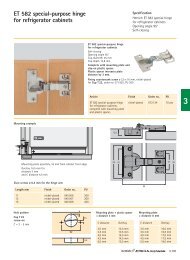
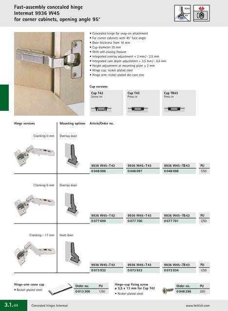
<strong>3.1.</strong>44 Fast-assembly concealed hinge Intermat 9936 W45 for corner cabinets, opening angle 95° Hinge versions Cranking 0 mm Cranking 6 mm Cranking - 17 mm Hinge-arm cover cap • Nickel-plated steel Mounting options Overlay door Overlay door Inset door • Concealed hinge for snap-on attachment • For corner cabinets with 45° face angle • Door thickness from 16 mm • Cup diameter 35 mm • With self-closing feature • Integrated overlay adjustment + 2 mm/- 2,5 mm • Integrated cam depth adjustment + 3,5 mm/- 0,5 mm • Height adjustment at mounting plate ± 2 mm • Hinge cup: nickel-plated steel • Hinge arm: nickel-plated die-cast zinc Cup versions Cup T42 Screw on Article/Order no. Order no. PU 0 013 300 1/50 Cup T43 Press-in Cup TB43 Press-in Concealed hinges Intermat www.hettich.com W45 45° 95° 9936 W45-T42 9936 W45-T43 9936 W45-TB43 0 048 096 0 048 097 0 048 098 9936 W45-T42 9936 W45-T43 9936 W45-TB43 0 077 699 0 077 700 0 077 701 9936 W45-T42 9936 W45-T43 9936 W45-TB43 0 073 932 0 073 933 0 073 934 Hinge-cup fixing screw ø 3,5 x 13 mm for Cup T42 • Nickel-plated steel PU 1/50 PU 1/50 PU 1/50 Order no. PU 0 048 296 200
Cup distance Door thickness mm C mm 16 17 18 19 20 21 22 23 24 25 26 27 28 29 30 31 32 Minimum reveal per door – allow for in distance calculation Table entries apply to doors with 0 mm radius 3 0,4 0,6 0,8 1,0 1,2 1,5 1,8 2,1 2,5 2,9 3,4 4,0 4,9 5,7 6,6 7,5 8,4 4 0,4 0,6 0,8 1,0 1,2 1,5 1,8 2,1 2,5 2,8 3,3 3,8 4,5 5,3 6,1 7,0 7,9 4,5 0,4 0,6 0,8 1,0 1,2 1,5 1,8 2,1 2,5 2,8 3,3 3,7 4,3 5,1 5,9 6,8 7,7 5 0,4 0,6 0,8 1,0 1,2 1,4 1,7 2,0 2,4 2,7 3,2 3,6 4,2 4,9 5,7 6,5 7,4 6 0,4 0,6 0,8 1,0 1,2 1,4 1,7 2,0 2,3 2,6 3,1 3,5 4,0 4,6 5,3 6,1 6,9 7 0,4 0,5 0,7 0,9 1,1 1,3 1,6 1,9 2,2 2,6 3,0 3,4 3,9 4,4 5,0 5,7 6,5 8 0,4 0,5 0,7 0,9 1,1 1,3 1,6 1,8 2,1 2,5 2,9 3,3 3,7 4,2 4,8 5,4 6,1 The minimum reveal is reduced for doors with radii: 1 mm radius: table entry – 0,4 mm 3 mm radius: table entry – 1,2 mm 52 ø35 C 5,5 11,1 52 11 11,1 T42 hole dimensions T43 hole dimensions TB43 hole dimensions Mounting examples Intermat 9936 W45 Overlay door Cranking 0 mm Overlay Cup distance C Side Distance D Door Silent System, see pages <strong>3.1.</strong>104 - <strong>3.1.</strong>118 Mounting plates, see pages <strong>3.1.</strong>88 - <strong>3.1.</strong>91 Technical information, see pages <strong>3.1.</strong>10 - <strong>3.1.</strong>11 Mounting configurations for various face angles, see pages <strong>3.1.</strong>93 - <strong>3.1.</strong>103 45° ø35 C 5,5 ø10 45 11 Fast-assembly concealed hinge Intermat 9936 W45 for corner cabinets, opening angle 95° ø35 C 9,5 ø8 11,1 Full overlay, cranking 0 mm Overlay adjustment + 2 mm / - 2,5 mm X Cabinet side C = 3 ... 8 mm Note: Drawings on this page are to full scale and show the hinges plus mounting plate distances. By drawing in the required cup distance C (3-8 mm), the door overlay can be measured directly from the applicable distance line. The distance from the cabinet front edge to X on the selected distance line is also equal to the hole line distance from the cabinet front edge. For inset-mounted doors, the cup distance and door thickness must be taken into account when determining the minimum reveal. ... Inside cabinet wall for D 8 mm ... for D 5 mm ... for D 3 mm ... for D 1,5 mm ... for D 0 mm 45° Hole line Scale 1:1 Concealed hinges Intermat <strong>3.1.</strong>45
- Page 1 and 2: 3.1 Concealed and single-pivot hing
- Page 3 and 4: i Minimat 3.1.152 - 3.1.161 Conceal
- Page 5 and 6: sensys Integrated dampening - quiet
- Page 7 and 8: Depth adjustment + 3 / - 2 mm Door
- Page 9 and 10: i Intermat 9904 W30 Opening angle 9
- Page 11 and 12: Visible quality Integrated overlay
- Page 13 and 14: i General determination of distance
- Page 15 and 16: Cup distance Door thickness mm C mm
- Page 17 and 18: Cup distance Door thickness mm C mm
- Page 19 and 20: Cup distance Door thickness mm C mm
- Page 21 and 22: Cup distance Door thickness mm C mm
- Page 23 and 24: Cup distance Door thickness mm C mm
- Page 25 and 26: Cup distance Door thickness mm C mm
- Page 27 and 28: Cup distance Door thickness mm C mm
- Page 29 and 30: Cup distance Door thickness mm C mm
- Page 31 and 32: Cup distance Door thickness mm C mm
- Page 33 and 34: Cup distance Door thickness mm C mm
- Page 35 and 36: Hairline reveal The entries in the
- Page 37 and 38: Fast-assembly concealed hinge Inter
- Page 39 and 40: Cup distance Door thickness mm C mm
- Page 41 and 42: Cup distance Door thickness mm C mm
- Page 43 and 44: Cup distance Door thickness mm C mm
- Page 45: Cup distance Door thickness mm C mm
- Page 49 and 50: Hinge versions W45 45° 95° Cranki
- Page 51 and 52: Full overlay, cranking 6 mm Overlay
- Page 53 and 54: Cup distance Door thickness mm C mm
- Page 55 and 56: Cup distance Door thickness mm C mm
- Page 57 and 58: Cup distance Door thickness mm C mm
- Page 59 and 60: Cup distance Door thickness mm C mm
- Page 61 and 62: Cup distance Door thickness mm C mm
- Page 63 and 64: Cup distance Door thickness mm C mm
- Page 65 and 66: Cup distance Door thickness mm C mm
- Page 67 and 68: Decorative cap A Decorative cap B F
- Page 69 and 70: Cup distance Door thickness mm C mm
- Page 71 and 72: Mounting plates, see pages 3.1.88 -
- Page 73 and 74: Cup distance Door thickness mm C mm
- Page 75 and 76: Mounting plates, see pages 3.1.88 -
- Page 77 and 78: Assembly: fixing screws 16,5 6 90°
- Page 79 and 80: F 65 43,6 Assembly 43,6 65 � �
- Page 81 and 82: Milling diagram 44 +0,2 22 +0,2 31
- Page 83 and 84: � 52 ø35 C 5,5 11,3 52 11 11,3 T
- Page 85 and 86: � Reveal ø35 Cabinet hinge, e.g.
- Page 87 and 88: Cup distance Door thickness mm C mm
- Page 89 and 90: Side 4,7 Overlay 5 ø35 52 T22 hole
- Page 91 and 92: 15 37 Mounting plate system 9000 fo
- Page 93 and 94: System 9000 angle and parallel adap
- Page 95 and 96: Mounting configurations for 40° to
- Page 97 and 98:
38 11 10 10 19 2 1 8 11 90° Interm
- Page 99 and 100:
39 19 1,5 4,5 75° 19 Intermat 9943
- Page 101 and 102:
35,5 4,5 36 16 2 4,5 3 16 110° Int
- Page 103 and 104:
48 4,5 6,5 19 5,5 19 135° Intermat
- Page 105 and 106:
120° 35 19 8 R 3 5,5 19 5,5 13 11
- Page 107 and 108:
… closing doors the gentle way Qu
- Page 109 and 110:
Screw-on door buffer 3.1.113 • In
- Page 111 and 112:
1 60 Screw-on door buffer Silent Sy
- Page 113 and 114:
Clip-on door buffer Screw-on door b
- Page 115 and 116:
Door buffer for overlay door 14,5 3
- Page 117 and 118:
K = Cranking 0 048 044 0 048 045 0
- Page 119 and 120:
Application for universal screw-on
- Page 121 and 122:
Designing without handles New desig
- Page 123 and 124:
i P2O Magnet XL Linear 3.1.126 •
- Page 125 and 126:
Assembly ø4 Push-To-Open Push-To-O
- Page 127 and 128:
16 1 8 Counterplate with socket •
- Page 129 and 130:
Assembly � � Push-To-Open ± 1,
- Page 131 and 132:
Assembly 10,5 � � � ø3,5 x 1
- Page 133 and 134:
Cup distance Door thickness mm C mm
- Page 135 and 136:
Fast-assembly concealed hinge for h
- Page 137 and 138:
Cup distance Door thickness mm C mm
- Page 139 and 140:
Mounting plates, see pages 3.1.88 -
- Page 141 and 142:
Full overlay Overlay adjustment + 2
- Page 143 and 144:
Fast-assembly concealed hinge for h
- Page 145 and 146:
3.1.143
- Page 147 and 148:
Concealed hinge Slide-on Hinge vers
- Page 149 and 150:
i Assembly Disassembly 12 Slide the
- Page 151 and 152:
Cup distance Door thickness mm C mm
- Page 153 and 154:
Article Distance Angle Order no. PU
- Page 155 and 156:
Miniature concealed hinge Minimat H
- Page 157 and 158:
2 i Assembly 1 The keyhole in the s
- Page 159 and 160:
Cup distance Door thickness mm C mm
- Page 161 and 162:
Decorative cap A Decorative cap B F
- Page 163 and 164:
Angle mounting plates and parallel
- Page 165 and 166:
With self-closing feature Opening a
- Page 167 and 168:
W 45 ! Cup Finishes Order no. PU hi
- Page 169 and 170:
Decorative cap A W 90 W 90 Order no
- Page 171 and 172:
Selekta Pro 2000 For single cabinet
- Page 173 and 174:
External pivot point: Opening angle
- Page 175 and 176:
Mounting position with 15 or 16 mm
- Page 177 and 178:
Mounting examples 21,2 37 21,2 37 2
- Page 179 and 180:
Cup T22/9 Cup T23/9 Cup TB 22 Cup T
- Page 181 and 182:
Mounting examples Single-pivot cup
- Page 183 and 184:
Mounting examples Single-pivot cup
- Page 185 and 186:
Mounting examples Single-pivot cup
- Page 187 and 188:
Cup T22/9 Cup T23/9 Cup TB 22 Cup T
- Page 189 and 190:
i Single-pivot hinge for office and
- Page 191 and 192:
Hole pattern door Hole pattern door
- Page 193 and 194:
3.1.191
- Page 195 and 196:
i Piano hinges 3.2.26 - 3.2.27 Doub
- Page 197 and 198:
• For overlay doors • For 10 an
- Page 199 and 200:
• For overlay and inset glass doo
- Page 201 and 202:
Mounting example 22 8 Side 23 Faste
- Page 203 and 204:
Mounting example min. 7,5 Side 9,3
- Page 205 and 206:
24 MASSIV SOLID MESSING BRASS 4,5 -
- Page 207 and 208:
• Door thickness from 15 mm • T
- Page 209 and 210:
Folding door hinge 625 32 9 8,5 19
- Page 211 and 212:
Mounting example 100 7,5 12,5 7,5 3
- Page 213 and 214:
Mounting example 8 Hole pattern 34
- Page 215 and 216:
MASSIV SOLID MESSING BRASS The Exce
- Page 217 and 218:
Mounting examples closed 2 2 Bottom
- Page 219 and 220:
MASSIV SOLID MESSING BRASS Hinge le
- Page 221 and 222:
• 32 mm open width • Knuckle le
- Page 223 and 224:
165° 130° Side panel mounting ove
- Page 225 and 226:
Mounting example Side Reveal F X 15
- Page 227 and 228:
7 63 24 24 29 46 31 2,5 20 16 ø4 5
- Page 229 and 230:
Mounting example Bottom Bottom Flap
- Page 231 and 232:
Mounting example Bottom Bottom Flap
- Page 233 and 234:
MASSIV SOLID MESSING BRASS Mounting
- Page 235 and 236:
MASSIV SOLID MESSING BRASS Mounting
- Page 237 and 238:
MASSIV SOLID MESSING BRASS Mounting
- Page 239 and 240:
3.2.45
- Page 241 and 242:
Finial butt hinge 270 3.3.15 - 3.3.
- Page 243 and 244:
Side 1 mm Reveal Door • Knuckle
- Page 245 and 246:
Mounting example Side MASSIV SOLID
- Page 247 and 248:
Mounting example MASSIV SOLID MESSI
- Page 249 and 250:
Side 1 mm Reveal Door • Knuckle
- Page 251 and 252:
• Knuckle ø 11 mm • Flap thick
- Page 253 and 254:
Mounting example Fasten with counte
- Page 255 and 256:
Mounting example MASSIV SOLID MESSI
- Page 257 and 258:
Mounting example MASSIV SOLID MESSI
- Page 259 and 260:
Mounting example MASSIV SOLID MESSI
- Page 261 and 262:
Mounting example Side MASSIV SOLID
- Page 263 and 264:
• Drawn brass, drilled and milled
- Page 265 and 266:
Mounting example • Drawn brass, d
- Page 267 and 268:
i Flap fitting system Lift Top Rang
- Page 269 and 270:
i Lift Top HL 3.4.8 - 3.4.9 Flap li
- Page 271 and 272:
Cabinet drilling pattern Internal c
- Page 273 and 274:
Internal cabinet height 234 - 682 C
- Page 275 and 276:
Cabinet drilling pattern 165 min. 2
- Page 277 and 278:
Cabinet drilling pattern min. 280 H
- Page 279 and 280:
i Lift Advanced HL 3.4.22 - 3.4.25
- Page 281 and 282:
Folding-flap fitting Lift Advanced
- Page 283 and 284:
B B1 550 - 925 B2 Cabinet drilling
- Page 285 and 286:
Flap fitting Lift Advanced HK Pneum
- Page 287 and 288:
B Cabinet drilling pattern Front dr
- Page 289 and 290:
Flap lift fitting Lift Advanced HL
- Page 291 and 292:
B Cabinet drilling pattern A Intern
- Page 293 and 294:
Lift-up flap fitting Lift Advanced
- Page 295 and 296:
B A Internal cabinet height Size mm
- Page 297 and 298:
Assembly Cabinet assembly � � F
- Page 299 and 300:
Assembly Cabinet assembly � � F
- Page 301 and 302:
Assembly Cabinet assembly Front pan
- Page 303 and 304:
Mounting example • Lift Junior 90
- Page 305 and 306:
Mounting example Guide values for f
- Page 307 and 308:
Mounting example Intermat 9943 44 M
- Page 309 and 310:
Mounting example Intermat 9943 235
- Page 311 and 312:
Mounting example Intermat 9943 125
- Page 313 and 314:
Flap connection with flap hinge Mar
- Page 315 and 316:
Mounting by milling 9 Screw-on moun
- Page 317 and 318:
Assembly notes Y X 42,5 40,5 20 Mar
- Page 319 and 320:
Mounting example 9 20 • With scre


![[International Design Award 2007] - Hettich](https://img.yumpu.com/6312597/1/190x135/international-design-award-2007-hettich.jpg?quality=85)