- Page 2 and 3:
INTERNATIONAL UNION OF CRYSTALLOGRA
- Page 4 and 5:
The Basics of Crystallography and D
- Page 6 and 7:
Preface to the First Edition (1997)
- Page 8 and 9:
Preface to Third Edition (2009) vii
- Page 10 and 11:
Contents X-ray photograph of zinc b
- Page 12 and 13:
Contents xi 6 The reciprocal lattic
- Page 14 and 15:
Contents xiii 11.4.1 Determining or
- Page 16 and 17:
X-ray photograph of deoxyribonuclei
- Page 18 and 19:
1 Crystals and crystal structures 1
- Page 20 and 21:
1.1 The nature of the crystalline s
- Page 22 and 23:
1.2 Constructing crystals from hexa
- Page 24 and 25:
1.3 Unit cells of the hcp and ccp s
- Page 26 and 27:
1.4 Constructing crystals from squa
- Page 28 and 29:
1.6 Interstitial structures 1.6 Int
- Page 30 and 31:
2r A 1.6 Interstitial structures 13
- Page 32 and 33:
1.6 Interstitial structures 15 a√
- Page 34 and 35:
1.6 Interstitial structures 17 (a)
- Page 36 and 37:
1.8 Representing crystals in projec
- Page 38 and 39:
1.9 Stacking faults and twins 21 Fi
- Page 40 and 41:
1.9 Stacking faults and twins 23 if
- Page 42 and 43:
1.9 Stacking faults and twins 25 tw
- Page 44 and 45:
1.10 The crystal chemistry of inorg
- Page 46 and 47:
1.10 The crystal chemistry of inorg
- Page 48 and 49:
1.11 Some more complex crystal stru
- Page 50 and 51:
1.11 Some more complex crystal stru
- Page 52 and 53:
1.11 Some more complex crystal stru
- Page 54 and 55:
1.11 Some more complex crystal stru
- Page 56 and 57:
1.11 Some more complex crystal stru
- Page 58 and 59:
1.11 Some more complex crystal stru
- Page 60 and 61:
1.11 Some more complex crystal stru
- Page 62 and 63:
1.11 Some more complex crystal stru
- Page 64 and 65:
1.11 Some more complex crystal stru
- Page 66 and 67:
1.11 Some more complex crystal stru
- Page 68 and 69:
1.11 Some more complex crystal stru
- Page 70 and 71:
Exercises 53 (c) (b) (a) Fig. 1.42.
- Page 72 and 73:
2 Two-dimensional patterns, lattice
- Page 74 and 75:
2.2 Two-dimensional patterns and la
- Page 76 and 77:
R 2.3 Two-dimensional symmetry elem
- Page 78 and 79:
2.4 The five plane lattices 61 mirr
- Page 80 and 81:
R R R R R R R R R R 2.4 The five pl
- Page 82 and 83:
2.7 Symmetry in art and design: cou
- Page 85:
(b) p1 pg p2 cm pm p2mm p2mg p2gg c
- Page 88:
What is the highest order of rotati
- Page 91 and 92:
2.7 Symmetry in art and design: cou
- Page 93 and 94:
2.8 Layer symmetry and examples in
- Page 95 and 96:
2.8 Layer symmetry and examples in
- Page 97 and 98:
2.9 Non-periodic patterns and tilin
- Page 99 and 100:
2.9 Non-periodic patterns and tilin
- Page 101 and 102:
Exercises 81 Fig. 2.20. A plane pat
- Page 103 and 104:
Exercises 83 (a) (b) (c) (d) (e) (f
- Page 105 and 106:
3.2 The fourteen space (Bravais) la
- Page 107 and 108:
3.2 The fourteen space (Bravais) la
- Page 109 and 110:
3.3 The symmetry of the fourteen Br
- Page 111:
System Bravais lattices Axial lengt
- Page 114 and 115:
3.4 The coordination or environment
- Page 116 and 117:
Exercises 95 Fig. 3.10. Epidermal c
- Page 118 and 119:
4 Crystal symmetry: point groups, s
- Page 120 and 121:
4.2 The thirty-two crystal classes
- Page 122 and 123:
4.3 Centres and inversion axes of s
- Page 124 and 125:
4.3 Centres and inversion axes of s
- Page 126 and 127:
4.4 Crystal symmetry and properties
- Page 128 and 129:
4.5 Translational symmetry elements
- Page 130 and 131:
4.5 Translational symmetry elements
- Page 132 and 133:
4.6 Space groups 111 the optical ac
- Page 134 and 135:
4.6 Space groups 113 P b a 2 C 8 2y
- Page 136 and 137:
4.6 Space groups 115 (b) 5 P 2 1 /c
- Page 138 and 139:
4.6 Space groups 117 that the coord
- Page 140 and 141:
4.7 Bravais lattices, space groups
- Page 142 and 143:
4.8 The crystal structures and spac
- Page 144 and 145:
4.8 The crystal structures and spac
- Page 146 and 147: 4.8 The crystal structures and spac
- Page 148 and 149: 4.9 Quasiperiodic crystals or cryst
- Page 150 and 151: 4.9 Quasiperiodic crystals or cryst
- Page 152 and 153: 5 Describing lattice planes and dir
- Page 154 and 155: 5.3 Indexing lattice planes—Mille
- Page 156 and 157: 5.3 Indexing lattice planes—Mille
- Page 158 and 159: 5.5 Lattice plane spacings, Miller
- Page 160 and 161: 5.6 Zones, zone axes and the zone l
- Page 162 and 163: 5.7 Indexing in the trigonal and he
- Page 164 and 165: 5.8 Transforming Miller indices and
- Page 166 and 167: 5.8 Transforming Miller indices and
- Page 168 and 169: 5.10 A simple method for inverting
- Page 170 and 171: Exercises Exercises 149 5.1 Write d
- Page 172 and 173: 6.2 Reciprocal lattice vectors 151
- Page 174 and 175: 6.3 Reciprocal lattice unit cells 1
- Page 176 and 177: 6.3 Reciprocal lattice unit cells 1
- Page 178 and 179: 6.4 Reciprocal lattice cells for cu
- Page 180 and 181: 6.5 Proofs of some geometrical rela
- Page 182 and 183: Hence: 6.6 Lattice planes and recip
- Page 184 and 185: 6.7 Summary 163 with their normal a
- Page 186 and 187: 7 The diffraction of light 7.1 Intr
- Page 188 and 189: 7.2 Simple observations of the diff
- Page 190 and 191: 7.2 Simple observations of the diff
- Page 192 and 193: 7.2 Simple observations of the diff
- Page 194 and 195: 7.3 The nature of light: coherence,
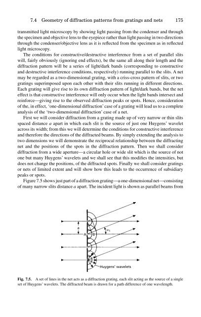
- Page 198 and 199: 7.4 Geometry of diffraction pattern
- Page 200 and 201: 7.4 Geometry of diffraction pattern
- Page 202 and 203: 7.5 The resolving power of optical
- Page 204 and 205: 7.5 The resolving power of optical
- Page 206 and 207: 7.5 The resolving power of optical
- Page 208 and 209: 7.5 The resolving power of optical
- Page 210 and 211: 7.5 The resolving power of optical
- Page 212 and 213: Exercises 191 pattern (see Figs. 1.
- Page 214 and 215: 8.2 Laue’s analysis of X-ray diff
- Page 216 and 217: 8.3 Laue’s analysis of X-ray diff
- Page 218 and 219: 8.3 Bragg’s analysis of X-ray dif
- Page 220 and 221: 8.4 Ewald’s synthesis: the reflec
- Page 222 and 223: 8.4 Ewald’s synthesis: the reflec
- Page 224 and 225: 9 The diffraction of X-rays 9.1 Int
- Page 226 and 227: 9.1 Introduction 205 (a) u u u u f
- Page 228 and 229: 9.2 The intensities of X-ray diffra
- Page 230 and 231: 9.2 The intensities of X-ray diffra
- Page 232 and 233: 9.2 The intensities of X-ray diffra
- Page 234 and 235: 9.2 The intensities of X-ray diffra
- Page 236 and 237: 9.3 The broadening of diffracted be
- Page 238 and 239: 9.3 The broadening of diffracted be
- Page 240 and 241: 9.3 The broadening of diffracted be
- Page 242 and 243: 9.4 Fixed θ, varying λ X-ray tech
- Page 244 and 245: 9.5 Fixed λ, varying θ X-ray tech
- Page 246 and 247:
[010] 9.5 Fixed λ, varying θ X-ra
- Page 248 and 249:
9.5 Fixed λ, varying θ X-ray tech
- Page 250 and 251:
9.6 X-ray diffraction from single c
- Page 252 and 253:
9.6 X-ray diffraction from single c
- Page 254 and 255:
9.7 X-ray (and neutron) diffraction
- Page 256 and 257:
9.7 X-ray (and neutron) diffraction
- Page 258 and 259:
9.8 Practical considerations: X-ray
- Page 260 and 261:
9.8 Practical considerations: X-ray
- Page 262 and 263:
Exercises 241 of the reciprocal lat
- Page 264 and 265:
10 X-ray diffraction of polycrystal
- Page 266 and 267:
10.2 X-ray diffraction 245 (a) S D
- Page 268 and 269:
10.2 X-ray diffraction 247 effect,
- Page 270 and 271:
10.2 X-ray diffraction 249 Square r
- Page 272 and 273:
10.2 X-ray diffraction 251 Focusing
- Page 274 and 275:
10.3 Applications of X-ray diffract
- Page 276 and 277:
10.3 Applications of X-ray diffract
- Page 278 and 279:
10.4 Preferred orientation and its
- Page 280 and 281:
10.4 Preferred orientation and its
- Page 282 and 283:
10.4 Preferred orientation and its
- Page 284 and 285:
10.5 X-ray diffraction of DNA: simu
- Page 286 and 287:
10.5 X-ray diffraction of DNA: simu
- Page 288 and 289:
10.6 The Rietveld method for struct
- Page 290 and 291:
10.6 The Rietveld method for struct
- Page 292 and 293:
Exercises 271 Given that the X-ray
- Page 294 and 295:
11 Electron diffraction and its app
- Page 296 and 297:
11.2 The Ewald reflecting sphere co
- Page 298 and 299:
11.3 The analysis of electron diffr
- Page 300 and 301:
11.3 The analysis of electron diffr
- Page 302 and 303:
11.4 Applications of electron diffr
- Page 304 and 305:
11.5 Kikuchi and electron backscatt
- Page 306 and 307:
11.5 Kikuchi and electron backscatt
- Page 308 and 309:
11.5 Kikuchi and electron backscatt
- Page 310 and 311:
220 11.6 Image formation and resolu
- Page 312 and 313:
11.6 Image formation and resolution
- Page 314 and 315:
Exercises 293 and hence, using the
- Page 316 and 317:
Exercises 295 11.5 Given the lattic
- Page 318 and 319:
12.1 Introduction 297 Fig. 12.1. A
- Page 320 and 321:
12.2 Construction of the stereograp
- Page 322 and 323:
12.2 Construction of the stereograp
- Page 324 and 325:
12.3 Manipulation of the stereograp
- Page 326 and 327:
12.4 Stereographic projections of n
- Page 328 and 329:
12.5 Stereographic projections of n
- Page 330 and 331:
12.5 Applications of the stereograp
- Page 332 and 333:
12.5 Applications of the stereograp
- Page 334 and 335:
12.5 Applications of the stereograp
- Page 336 and 337:
13 Fourier analysis in diffraction
- Page 338 and 339:
13.1 Introduction—Fourier series
- Page 340 and 341:
13.2 Fourier analysis in crystallog
- Page 342 and 343:
13.2 Fourier analysis in crystallog
- Page 344 and 345:
13.3 Analysis of the Fraunhofer dif
- Page 346 and 347:
13.3 Analysis of the Fraunhofer dif
- Page 348 and 349:
13.3 Analysis of the Fraunhofer dif
- Page 350 and 351:
13.4 Abbe theory of image formation
- Page 352 and 353:
13.4 Abbe theory of image formation
- Page 354 and 355:
Appendix 1 Computer programs, model
- Page 356 and 357:
Appendix 1 335 CRYSTALS is availabl
- Page 358 and 359:
Appendix 1 337 Fig. A1.2. Models sh
- Page 360 and 361:
Appendix 2 Polyhedra in crystallogr
- Page 362 and 363:
Appendix 2 341 Fig. A2.2. The five
- Page 364 and 365:
Appendix 2 343 Of these thirteen po
- Page 366 and 367:
Appendix 2 345 (a) (b) (c) Fig. A2.
- Page 368 and 369:
Appendix 2 347 next Brillouin zone
- Page 370 and 371:
Appendix 3 Biographical notes on cr
- Page 372 and 373:
Appendix 3 351 it did nevertheless
- Page 374 and 375:
Appendix 3 353 Lawrence. Gwen immer
- Page 376 and 377:
Appendix 3 355 mathematics and phys
- Page 378 and 379:
Appendix 3 357 Martin Julian Buerge
- Page 380 and 381:
Appendix 3 359 Fourier’s main ach
- Page 382 and 383:
Appendix 3 361 of high humidity) ha
- Page 384 and 385:
Appendix 3 363 dome covering the Fo
- Page 386 and 387:
Appendix 3 365 Christiaan Huygens 1
- Page 388 and 389:
Appendix 3 367 Cambridge was purcha
- Page 390 and 391:
Appendix 3 369 Kathleen Lonsdale (a
- Page 392 and 393:
Appendix 3 371 Isaac Newton was bor
- Page 394 and 395:
Appendix 3 373 optical activity, cr
- Page 396 and 397:
Appendix 3 375 Jean Baptiste Louis
- Page 398 and 399:
Appendix 3 377 In 1925 Wulff died a
- Page 400 and 401:
Appendix 3 379 both from boyhood as
- Page 402 and 403:
Appendix 3 381 the Royal Society as
- Page 404 and 405:
Appendix 4 383 Hexagonal: cos ρ =
- Page 406 and 407:
Appendix 5 A simple introduction to
- Page 408 and 409:
Appendix 5 387 3b r b a 5a Fig. A5.
- Page 410 and 411:
Appendix 5 389 (all the other terms
- Page 412 and 413:
Appendix 5 391 ’imaginary’ axis
- Page 414 and 415:
Appendix 6 393 Fig. A6.1. Writing d
- Page 416 and 417:
these two values in the structure f
- Page 418 and 419:
Table A6.1 Appendix 6 397 Extinctio
- Page 420 and 421:
Appendix 6 399 etc. in the row thro
- Page 422 and 423:
Answers to exercises Chapter 1 1.1
- Page 424 and 425:
Answers to exercises 403 common clo
- Page 426 and 427:
Answers to exercises 405 (c) p = 61
- Page 428 and 429:
Answers to exercises 407 Diffractio
- Page 430 and 431:
Answers to exercises 409 C/C * rota
- Page 432 and 433:
Answers to exercises 411 11.5 In Fi
- Page 434 and 435:
Answers to exercises 413 -x Small c
- Page 436 and 437:
Further Reading 415 Books which cov
- Page 438 and 439:
Further Reading 417 Williams, D. B.
- Page 440 and 441:
Further Reading 419 impressions is
- Page 442 and 443:
Index Note: Illustrations are indic
- Page 444 and 445:
Index 423 point group symbols for 1
- Page 446 and 447:
Index 425 Hanawalt groups 254 Hanaw
- Page 448 and 449:
Index 427 model building 5, 337-8 m
- Page 450 and 451:
Index 429 rotation-reflection (mirr
- Page 452 and 453:
Index 431 stacking sequence (in clo