3-way ball valve with female thread - sauter-controls.com sauter ...
3-way ball valve with female thread - sauter-controls.com sauter ...
3-way ball valve with female thread - sauter-controls.com sauter ...

Create successful ePaper yourself
Turn your PDF publications into a flip-book with our unique Google optimized e-Paper software.
Regulating <strong>valve</strong>s, <strong>com</strong>bined <strong>with</strong> actuator<br />
PDS 56.091 en Product Data Sheet BKR015...050<br />
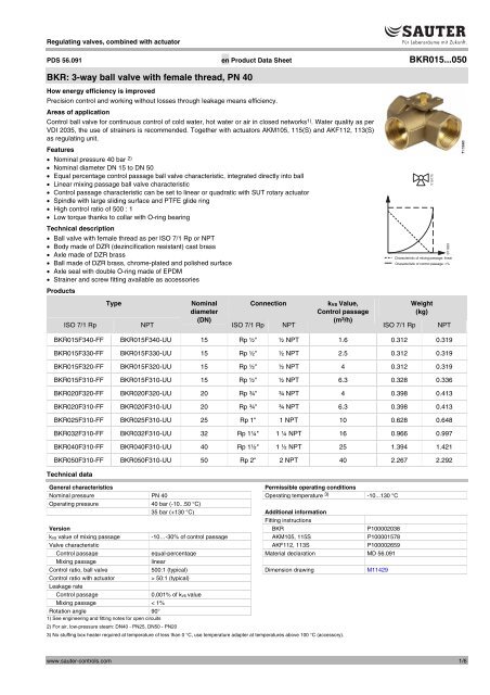
BKR: 3-<strong>way</strong> <strong>ball</strong> <strong>valve</strong> <strong>with</strong> <strong>female</strong> <strong>thread</strong>, PN 40<br />
How energy efficiency is improved<br />
Precision control and working <strong>with</strong>out losses through leakage means efficiency.<br />
Areas of application<br />
Control <strong>ball</strong> <strong>valve</strong> for continuous control of cold water, hot water or air in closed networks1). Water quality as per<br />
VDI 2035, the use of strainers is re<strong>com</strong>mended. Together <strong>with</strong> actuators AKM105, 115(S) and AKF112, 113(S)<br />
as regulating unit.<br />
Features<br />
� Nominal pressure 40 bar 2)<br />
� Nominal diameter DN 15 to DN 50<br />
� Equal percentage control passage <strong>ball</strong> <strong>valve</strong> characteristic, integrated directly into <strong>ball</strong><br />
� Linear mixing passage <strong>ball</strong> <strong>valve</strong> characteristic<br />
� Control passage characteristic can be set to linear or quadratic <strong>with</strong> SUT rotary actuator<br />
� Spindle <strong>with</strong> large sliding surface and PTFE glide ring<br />
� High control ratio of 500 : 1<br />
� Low torque thanks to collar <strong>with</strong> O-ring bearing<br />
Technical description<br />
� Ball <strong>valve</strong> <strong>with</strong> <strong>female</strong> <strong>thread</strong> as per ISO 7/1 Rp or NPT<br />
� Body made of DZR (dezincification resistant) cast brass<br />
� Axle made of DZR brass<br />
� Ball made of DZR brass, chrome-plated and polished surface<br />
� Axle seal <strong>with</strong> double O-ring made of EPDM<br />
� Strainer and screw fitting available as accessories<br />
Products<br />
Y10175<br />
B11839<br />
Characteristic of mixing passage: linear<br />
Characteristic of control passage: =%<br />
Type Nominal<br />
Connection kvs Value,<br />
Weight<br />
diameter<br />
Control passage<br />
(kg)<br />
ISO 7/1 Rp NPT<br />
(DN)<br />
ISO 7/1 Rp NPT<br />
(m3/h) ISO 7/1 Rp NPT<br />
BKR015F340-FF BKR015F340-UU 15 Rp ½" ½ NPT 1.6 0.312 0.319<br />
BKR015F330-FF BKR015F330-UU 15 Rp ½" ½ NPT 2.5 0.312 0.319<br />
BKR015F320-FF BKR015F320-UU 15 Rp ½" ½ NPT 4 0.312 0.319<br />
BKR015F310-FF BKR015F310-UU 15 Rp ½" ½ NPT 6.3 0.328 0.336<br />
BKR020F320-FF BKR020F320-UU 20 Rp ¾" ¾ NPT 4 0.398 0.413<br />
BKR020F310-FF BKR020F310-UU 20 Rp ¾" ¾ NPT 6.3 0.398 0.413<br />
BKR025F310-FF BKR025F310-UU 25 Rp 1" 1 NPT 10 0.628 0.648<br />
BKR032F310-FF BKR032F310-UU 32 Rp 1¼" 1 ¼ NPT 16 0.966 0.997<br />
BKR040F310-FF BKR040F310-UU 40 Rp 1½" 1 ½ NPT 25 1.394 1.421<br />
BKR050F310-FF BKR050F310-UU 50 Rp 2" 2 NPT 40 2.267 2.292<br />
Technical data<br />
General characteristics Permissible operating conditions<br />
Nominal pressure PN 40 Operating temperature 3) -10...130 °C<br />
Operating pressure 40 bar (-10...50 °C)<br />
35 bar (+130 °C) Additional information<br />
Fitting instructions<br />
Version BKR P100002038<br />
kvs value of mixing passage -10…-30% of control passage AKM105, 115S P100001578<br />
Valve characteristic AKF112, 113S P100002659<br />
Control passage equal-percentage Material declaration MD 56.091<br />
Mixing passage linear<br />
Control ratio, <strong>ball</strong> <strong>valve</strong> 500:1 (typical) Dimension drawing M11429<br />
Control ratio <strong>with</strong> actuator<br />
Leakage rate<br />
> 50:1 (typical)<br />
Control passage 0,001% of kvs value<br />
Mixing passage < 1%<br />
Rotation angle 90°<br />
1) See engineering and fitting notes for open circuits<br />
2) For air, low-pressure steam: DN40 - PN25, DN50 - PN20<br />
3) No stuffing box heater required at temperature of less than 0 °C, use temperature adapter at temperatures above 100 °C (accessory).<br />
www.<strong>sauter</strong>-<strong>controls</strong>.<strong>com</strong> 1/6
Accessories<br />
Type Description<br />
0510420001* Temperature adapter (>100 °C to max. 130 °C) for AKM and AKF, P100002660<br />
0560283015* 1 screw fitting made from brass for DN 15 <strong>female</strong> <strong>thread</strong><br />
0560283020* 1 screw fitting made from brass for DN 20 <strong>female</strong> <strong>thread</strong><br />
0560283025* 1 screw fitting made from brass for DN 25 <strong>female</strong> <strong>thread</strong><br />
0560283032* 1 screw fitting made from brass for DN 32 <strong>female</strong> <strong>thread</strong><br />
0560283040* 1 screw fitting made from brass for DN 40 <strong>female</strong> <strong>thread</strong><br />
0560283050* 1 screw fitting made from brass for DN 50 <strong>female</strong> <strong>thread</strong><br />
0560332015* Strainer made from gun metal, -10 - 150°C, mesh aperture 0,5 mm, DN 15<br />
0560332020* Strainer made from gun metal, -10 - 150°C, mesh aperture 0,8 mm, DN 20<br />
0560332025* Strainer made from gun metal, -10 - 150°C, mesh aperture 0,8 mm, DN 25<br />
0560332032* Strainer made from gun metal, -10 - 150°C, mesh aperture 0,8 mm, DN 32<br />
0560332040* Strainer made from gun metal, -10 - 150°C, mesh aperture 0,8 mm, DN 40<br />
0560332050* Strainer made from gun metal, -10 - 150°C, mesh aperture 0,8 mm, DN 50<br />
*) Dimension drawing or connection diagram available under same number<br />
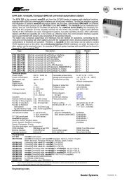
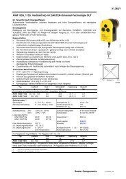
Combination of BKR and electric rotary actuator<br />
B11863<br />
Actuator<br />
Running<br />
time:<br />
Input:<br />
Ball Valve<br />
AKM105<br />
35 s<br />
2-/3-pt<br />
Against pressure Against pressure<br />
�pmax �ps close/off<br />
pressure<br />
�pmax �ps close/off<br />
pressure<br />
BKR015 1.8 – 1.8 2 – 6<br />
BKR020 1.8 – 1.8 2 – 6<br />
BKR025 1.8 – 1.8 2 – 6<br />
BKR032 1.2 – 1.2 2 – 6<br />
BKR040 1.2 – 1.2 2 – 6<br />
BKR050 1.2 – 1.2<br />
Combination of BKR and electric rotary actuator <strong>with</strong> spring return<br />
B11862<br />
Actuator<br />
Running time:<br />
Motor:<br />
Spring:<br />
Input:<br />
Ball Valve<br />
Against pressure<br />
�pmax �ps close/off<br />
pressure<br />
BKR015 2 5.4 6<br />
BKR020 2 5.4 6<br />
BKR025 2 5.4 6<br />
BKR032 2 3.5 6<br />
BKR040 2 3.5 6<br />
BKR050 2 3.5 6<br />
AKF112F120<br />
90 s<br />
15 s<br />
2-pt<br />
230 V<br />
2 – 6<br />
AKF112F122<br />
90 s<br />
15 s<br />
2-pt<br />
24 V<br />
AKM115F12.<br />
120 s<br />
2-/3-pt<br />
AKF113F122<br />
90 s<br />
15 s<br />
3-pt<br />
24 V<br />
BKR015...050<br />
AKM115S<br />
35/ 60/120 s<br />
2-/3-pt<br />
0…10 V<br />
AKF113SF122<br />
90 s<br />
15 s<br />
0…10 V<br />
24 V<br />
2/6 www.<strong>sauter</strong>-<strong>controls</strong>.<strong>com</strong>
BKR015...050<br />
Valve: F variant, see <strong>valve</strong> type table for technical data and accessories<br />
Actuators: F variant, see section 51 for technical data, accessories and installation position<br />
Example: BKR015F310 / AKM115SF132<br />
�p<br />
max<br />
[bar]= Maximum permissible pressure difference across the <strong>valve</strong> at which the drive can still reliably open and close the <strong>valve</strong> taking �p<br />
v<br />
into consideration.<br />
�p<br />
s<br />
[bar]= Maximum permissible pressure difference across the <strong>valve</strong> in the event of a problem (pipeline break downstream of <strong>valve</strong>) at which the drive can reliably close <strong>with</strong> “fast”<br />
stroke passage<br />
close/off Maximum possible pressure difference across the <strong>valve</strong> during control operation at which the drive can still open and close the <strong>valve</strong>. A shorter service life can be expected<br />
pressure [bar]= if this method is used. Cavitation, erosion and pressure surges can damage the <strong>valve</strong>. The values only apply to the assembled <strong>com</strong>bination of the <strong>valve</strong> fitted to the drive.<br />
Operation<br />
Using an electric actuator, the three-<strong>way</strong> <strong>ball</strong> <strong>valve</strong> can be moved to<br />
any position. Using either the AKM105/115(S) actuator or the<br />
AKF112/113(S) actuator <strong>with</strong> spring return, it is possible to<br />
implement a mixing function across the three-<strong>way</strong> <strong>ball</strong> <strong>valve</strong>. A<br />
diverting function is not permissible.<br />
Direction of flow<br />
A AB<br />
B<br />
Description<br />
These <strong>ball</strong> <strong>valve</strong>s are notable for their great reliability and accuracy,<br />
and make a major contribution to providing environmentally-friendly<br />
control. They <strong>com</strong>ply <strong>with</strong> the most demanding requirements, such<br />
as a quick-closing function, coping <strong>with</strong> differential pressures,<br />
controlling media temperatures and providing a shut-off facility –<br />
and almost silently.<br />
The spindle of the <strong>ball</strong> <strong>valve</strong> is automatically connected to the pin of<br />
the actuator. The brass <strong>ball</strong> regulates an equal-percentage flow in<br />
the control passage and a linear flow in the mixing passage. The<br />
tightness of the <strong>ball</strong> is safeguarded by the PTFE collars that are<br />
fitted in the body. An EPDM O-ring is inserted behind these two<br />
collars in the control passage. These O-rings permit the <strong>ball</strong> and<br />
both collars to make a small axial movement, which provides an<br />
extremely good seal and generates little torque.<br />
The tightness of the spindle is safeguarded by two O-rings; these<br />
cannot be replaced.<br />
Engineering and fitting notes<br />
The <strong>ball</strong> <strong>valve</strong>s are <strong>com</strong>bined <strong>with</strong> rotary actuators <strong>with</strong> or <strong>with</strong>out<br />
spring return. The actuator is directly attached to the <strong>ball</strong> <strong>valve</strong> and<br />
held in place by a bayonet connection. The actuator axle is<br />
connected to the spindle automatically, for which purpose the axle<br />
of the <strong>ball</strong> <strong>valve</strong> should be in an intermediate position. When the<br />
system is being put into service, the SUT actuator moves to the<br />
open position (for the control passage), and both devices are<br />
connected automatically. The angle of rotation of the <strong>ball</strong> <strong>valve</strong> is<br />
also detected by the actuator; no further settings are necessary.<br />
These SUT actuators allow the characteristic of the control passage<br />
to be changed from linear to quadratic or vice versa. In order to<br />
prevent the <strong>ball</strong> <strong>valve</strong> from blocking in the end positions, the SUT<br />
actuator makes a movement of about 30° if the positioning signal<br />
has not changed in the end positions for three days.<br />
In order to prevent impurities (e.g. welding beads, rust particles<br />
etc.) from entering the water and damaging the PTFE collars,<br />
strainers (dirt traps) should be fitted, e.g. on each floor or in each<br />
duct run. For strainers, see accessories; observe usage<br />
re<strong>com</strong>mendations and temperature range for each type. The<br />
<strong>com</strong>position of the water should be in accordance <strong>with</strong> VDI2035.<br />
All <strong>ball</strong> <strong>valve</strong>s should be used only in closed circuits. If used in open<br />
circuits, an excessive oxygen mixture may damage the <strong>ball</strong> <strong>valve</strong>s.<br />
To prevent this from happening, use an oxygen binding agent, but<br />
consult the manufacturer of the binding agent <strong>with</strong> regard to<br />
<strong>com</strong>patibility and corrosion. Please refer to the materials list below.<br />
The fittings are usually insulated in the systems. However, the<br />
flange that holds the actuator should not be insulated.<br />
In order to prevent flow noise in quiet rooms, the pressure<br />
difference across the <strong>ball</strong> <strong>valve</strong> should not exceed 50% of the<br />
specified values.<br />
The crank handle is fixed to the actuator. To operate the crank<br />
handle, the manual adjuster on the actuator should be pushed<br />
downwards, The actuator will not operate until this knob is moved<br />
back to the upper position. There is also a squared end on the<br />
crank handle that matches the squared end of the <strong>ball</strong> <strong>valve</strong>'s<br />
spindle.<br />
Using <strong>with</strong> water<br />
When using water, mixed <strong>with</strong> glycol or an inhibitor, consult the<br />
manufacturer <strong>with</strong> regard to the <strong>com</strong>patibility of the materials and<br />
seals used in the <strong>ball</strong> <strong>valve</strong>s. Please refer to the list of materials<br />
shown in Material Declaration MD 56.091. If glycol is used, we<br />
re<strong>com</strong>mend a concentration of between 20% and 50%.<br />
The <strong>ball</strong> <strong>valve</strong>s are not suitable for use in potentially explosive<br />
areas. The materials that have been selected have been approved<br />
for use <strong>with</strong> drinking water. The <strong>ball</strong> <strong>valve</strong> as a whole has not been<br />
certified for use <strong>with</strong> drinking water.<br />
Permissible fitting positions<br />
The control unit can be fitted in any position; however, we do not<br />
re<strong>com</strong>mend fitting it in the upside-down position. The ingress of<br />
condensate, drops of water etc. into the actuator should be<br />
prevented.<br />
www.<strong>sauter</strong>-<strong>controls</strong>.<strong>com</strong> 3/6
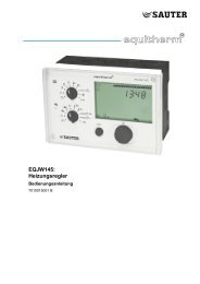
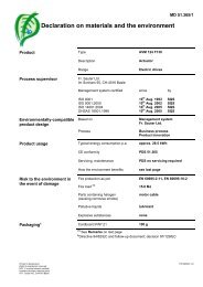
Flow diagram<br />
BKR<br />
1 10<br />
�p � v100 [kPa]<br />
100 1000<br />
100,00<br />
28<br />
V100<br />
[m³/h]<br />
10,00<br />
1,00<br />
k 40,0<br />
0,028<br />
0,10<br />
1,2<br />
0,01 0,1 1 2 10<br />
�p � v100 [bar]<br />
�p � v = 1,2 bar<br />
��p<br />
v = 2 bar<br />
Luft, Niederdruckdampf<br />
Wasser, Wasser-Glycol<br />
Air, vapeur basse pression<br />
Eau, eau-glycol<br />
Air, low pressure steam<br />
Water, water-glycol<br />
vs<br />
k 25,0<br />
k 16,0<br />
vs<br />
vs<br />
k 10,0<br />
vs<br />
k 6,3<br />
vs<br />
k 4,0<br />
vs<br />
k 2,5<br />
vs<br />
k 1,6<br />
Additional technical data<br />
Technical information<br />
Pressure<br />
specifications<br />
and temperature EN 764, EN 1333<br />
Flow parameters EN 60534 Page 3<br />
Manual: 'Valves and actuators' 7000477001<br />
Parameters & fitting notes<br />
Control, general information<br />
Valid EN & DIN regulations<br />
Additional specifications<br />
The body of the <strong>ball</strong> <strong>valve</strong> is made from DZR moulded brass<br />
(EN 12165) <strong>with</strong> cylindrical <strong>female</strong> <strong>thread</strong> as per ISO 7/1 Rp.<br />
Spindle seal <strong>with</strong> double O-ring of ethylene propylene.<br />
Material numbers as per DIN<br />
DIN material no. DIN code<br />
Body of <strong>ball</strong> <strong>valve</strong> CW602N CuZn36Pb2As<br />
Connection CW602N CuZn36Pb2As<br />
Ball, polished, chrome-plated CW602N CuZn36Pb2As<br />
Spindle CW602N CuZn36Pb2As<br />
O-ring EPDM<br />
Collar PTFE<br />
Explanation of terms used<br />
�pv:<br />
Maximum permissible pressure difference across the <strong>valve</strong> in any<br />
stroke position, limited by the noise level and erosion.<br />
vs<br />
V100<br />
[l/s]<br />
2,80<br />
0,28<br />
BKR015...050<br />
The <strong>valve</strong>, as a traversed element, is characterised by this<br />
parameter specifically in its hydraulic behaviour. By monitoring<br />
cavitation, erosion and the noise thus produced, improvements can<br />
be achieved in both life expectancy and operational capacity.<br />
�pmax:<br />
Maximum permissible pressure difference across the <strong>valve</strong> at<br />
which the actuator can reliably open and close the <strong>valve</strong>.<br />
Static pressure and fluidic influences are taken into account. This<br />
value helps to maintain a smooth stroke action and the high level<br />
of sealing. In doing so, the <strong>valve</strong>'s �pv value is never exceeded.<br />
�ps:<br />
Maximum permissible pressure difference across the <strong>valve</strong> in the<br />
event of a malfunction (e.g. power failure, excess temperature or<br />
pressure, burst pipe) at which the actuator can firmly close the<br />
<strong>valve</strong> and, if necessary, hold the full operating pressure against<br />
atmospheric pressure. Since this is a quick-closing function <strong>with</strong><br />
'fast' rotation, �ps can be greater than �pmax or. �pv. The resultant<br />
fluidic disturbances are soon over<strong>com</strong>e and play a minor role here.<br />
�pstat:<br />
Line pressure behind the <strong>valve</strong>. This corresponds largely to the<br />
dead pressure when the pump is switched off, e.g. due to the level<br />
of liquid in the installation, an increase in pressure via the pressure<br />
store, steam pressure etc.<br />
4/6 www.<strong>sauter</strong>-<strong>controls</strong>.<strong>com</strong><br />
B11838
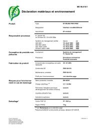
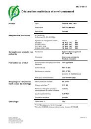
BKR015...050<br />
Characteristic of control passage on actuators <strong>with</strong> positioner<br />
On AKM115S actuator<br />
Control passage: equal-percentage/linear/quadratic<br />
Mixing passage: linear<br />
Dimension drawing<br />
c<br />
L<br />
DN A<br />
mm<br />
A<br />
G<br />
H<br />
B<br />
mm<br />
�9 0<br />
-0,06<br />
B<br />
10<br />
c<br />
mm<br />
M11429<br />
www.<strong>sauter</strong>-<strong>controls</strong>.<strong>com</strong> 5/6<br />
L<br />
mm<br />
k VS<br />
100 %<br />
90<br />
80<br />
70<br />
60<br />
50<br />
40<br />
30<br />
20<br />
10<br />
lin.<br />
lin.<br />
quadr.<br />
= %<br />
0<br />
0 10 20 30 40 50 60 70 80 90 100 %<br />
Hub, Course, Stroke<br />
L<br />
mm<br />
15 21 34 24 (28)* 67 67 Rp ½ 26<br />
20 21 37 28 72 72 Rp ¾ 31<br />
25 21 45 31 85 85 Rp 1 39<br />
32 24 53 34 99 99 Rp 1¼ 48<br />
40 28 57 40 110 110 Rp 1½ 55<br />
50 34 69 53<br />
* Dimension c equals 28 mm on types . . F310-FF<br />
NPT<br />
Combinations<br />
AKM105/115(S)<br />
131<br />
* <strong>with</strong> accessory 051048000 : 72 mm<br />
ISO 7/1 Rp<br />
131<br />
ISO 7/1 Rp<br />
G<br />
H<br />
mm<br />
Rp 2 67<br />
126<br />
B11840<br />
40*<br />
130<br />
c<br />
K10481
Dimension drawing (continued)<br />
G1<br />
c<br />
H1<br />
AKF112/113(S)<br />
Accessories<br />
05603320 …<br />
b<br />
05602830 …<br />
L<br />
L<br />
b1 b2<br />
© Fr. Sauter AG<br />
Im Surinam 55<br />
CH-4016 Basle<br />
Tel. +41 61 - 695 55 55<br />
Fax +41 61 - 695 55 10<br />
www.<strong>sauter</strong>-<strong>controls</strong>.<strong>com</strong><br />
info@<strong>sauter</strong>-<strong>controls</strong>.<strong>com</strong><br />
b<br />
G2<br />
H2 Z10224<br />
G<br />
H<br />
Z10221<br />
DN b1<br />
mm<br />
c 104,3<br />
40<br />
BKR015...050<br />
6/6 www.<strong>sauter</strong>-<strong>controls</strong>.<strong>com</strong><br />
7156091003 02<br />
K10480<br />
DN b<br />
mm<br />
60<br />
c<br />
mm<br />
G<br />
inch<br />
L<br />
mm<br />
H<br />
mm<br />
15 12 38 G ½ 54 27<br />
20 15 43 G ¾ 67 34<br />
25 16 53 G 1 79 41<br />
32 17 64 G 1¼ 98 51<br />
40 18 70 G 1½ 106 57<br />
50 20 85<br />
b2<br />
mm<br />
G1<br />
inch<br />
ISO 228-1<br />
G 2 122 69<br />
G2<br />
inch<br />
L<br />
mm<br />
H1<br />
mm<br />
15 10 10 Rp ½ G ½ 46 26 30<br />
20 12 12 Rp ¾ G ¾ 52 31 37<br />
25 14 14<br />
ISO<br />
7/1<br />
Z10222<br />
H2<br />
mm<br />
Rp 1 G 1 60 40 46<br />
32 16 16 G 1¼ G 1¼ 65 50 54<br />
40 17 17 G 1½ G 1½ 76 54 64<br />
50 20 20<br />
ISO<br />
228-1<br />
G 2<br />
Accessories<br />
0510420001<br />
ISO 228-1<br />
G 2 98 69 81<br />
Printed in Switzerland