Redundancy and Load Balancing - Router Alley
Redundancy and Load Balancing - Router Alley
Redundancy and Load Balancing - Router Alley

Create successful ePaper yourself
Turn your PDF publications into a flip-book with our unique Google optimized e-Paper software.
<strong>Redundancy</strong> <strong>and</strong> <strong>Load</strong> <strong>Balancing</strong> v1.21 – Aaron Balchunas<br />
- <strong>Redundancy</strong> <strong>and</strong> <strong>Load</strong> <strong>Balancing</strong> -<br />
Importance of <strong>Redundancy</strong><br />
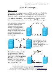
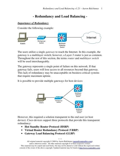
Consider the following example:<br />
The users utilize a single gateway to reach the Internet. In this example, the<br />
gateway is a multilayer switch; however, a Layer-3 router is just as common.<br />
Throughout the rest of this section, the terms router <strong>and</strong> multilayer switch<br />
will be used interchangeably.<br />
The gateway represents a single point of failure on this network. If that<br />
gateway fails, users will lose access to all resources beyond that gateway.<br />
This lack of redundancy may be unacceptable on business-critical systems<br />
that require maximum uptime.<br />
It is possible to provide multiple gateways for host devices:<br />
However, this required a solution transparent to the end user (or host<br />
device). Cisco devices support three protocols that provide this transparent<br />
redundancy:<br />
• Hot St<strong>and</strong>by <strong>Router</strong> Protocol (HSRP)<br />
• Virtual <strong>Router</strong> <strong>Redundancy</strong> Protocol (VRRP)<br />
• Gateway <strong>Load</strong> <strong>Balancing</strong> Protocol (GLBP)<br />
* * *<br />
All original material copyright © 2009 by Aaron Balchunas (aaron@routeralley.com),<br />
unless otherwise noted. All other material copyright © of their respective owners.<br />
This material may be copied <strong>and</strong> used freely, but may not be altered or sold without the expressed written<br />
consent of the owner of the above copyright. Updated material may be found at http://www.routeralley.com.<br />
1
Hot St<strong>and</strong>by <strong>Router</strong> Protocol (HSRP)<br />
<strong>Redundancy</strong> <strong>and</strong> <strong>Load</strong> <strong>Balancing</strong> v1.21 – Aaron Balchunas<br />
Cisco developed a proprietary protocol named Hot St<strong>and</strong>by <strong>Router</strong><br />
Protocol (HSRP) that allows multiple routers or multilayer switches to<br />
masquerade as a single gateway. This is accomplished by assigning a virtual<br />
IP address to all routers participating in HSRP.<br />
All routers are assigned to a single HSRP group (numbered 0-255). Note<br />
however, that most Catalyst switches will support only 16 configured HSRP<br />
groups. HSRP routers are elected to specific roles:<br />
• Active <strong>Router</strong> – the router currently serving as the gateway.<br />
• St<strong>and</strong>by <strong>Router</strong> – the backup router to the Active <strong>Router</strong>.<br />
• Listening <strong>Router</strong> – all other routers participating in HSRP.<br />
Only one Active <strong>and</strong> one St<strong>and</strong>by router are allowed per HSRP group.<br />
HSRP routers regularly send Hello packets (by default, every 3 seconds) to<br />
ensure all routers are functioning. If the current Active <strong>Router</strong> fails, the<br />
St<strong>and</strong>by <strong>Router</strong> is made active, <strong>and</strong> a new St<strong>and</strong>by is elected.<br />
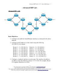
The role of an HSRP router is dictated by its priority. The priority can range<br />
from 0 – 255, with a default of 100. The router with the highest (a higher<br />
value is better) priority is elected the Active <strong>Router</strong>; the router with the<br />
second highest priority becomes the St<strong>and</strong>by <strong>Router</strong>. If all priorities are<br />
equal, whichever router has the highest IP Address on its HSRP interface is<br />
elected the Active <strong>Router</strong>.<br />
In the above example, Switch 2 would become the Active HSRP router, as it<br />
has the highest priority. Switch 1 would become the St<strong>and</strong>by router.<br />
* * *<br />
All original material copyright © 2009 by Aaron Balchunas (aaron@routeralley.com),<br />
unless otherwise noted. All other material copyright © of their respective owners.<br />
This material may be copied <strong>and</strong> used freely, but may not be altered or sold without the expressed written<br />
consent of the owner of the above copyright. Updated material may be found at http://www.routeralley.com.<br />
2
HSRP States<br />
<strong>Redundancy</strong> <strong>and</strong> <strong>Load</strong> <strong>Balancing</strong> v1.21 – Aaron Balchunas<br />
A router or multilayer switch configured for HSRP will progress through<br />
several states before settling into a role:<br />
• Disabled – the interfaces is not configured for HSRP, or is<br />
administratively shut down.<br />
• Init – this is the starting state when an interface is first brought up.<br />
• Learn – the router is waiting to hear hellos from the Active <strong>Router</strong>, to<br />
learn the configured Virtual Address.<br />
• Listen – the router has learned the Virtual IP address, but was not<br />
elected the Active or St<strong>and</strong>by <strong>Router</strong>.<br />
• Speak – the router is currently participating in an Active <strong>Router</strong><br />
election, <strong>and</strong> is sending Hello packets.<br />
• St<strong>and</strong>by – the router is acting as a backup to the Active <strong>Router</strong>.<br />
St<strong>and</strong>by routers monitor <strong>and</strong> send hellos to the Active <strong>Router</strong>.<br />
• Active – the router is currently accepting <strong>and</strong> forwarding user traffic,<br />
using the Virtual IP address. The Active <strong>Router</strong> actively exchanges<br />
hellos with the St<strong>and</strong>by <strong>Router</strong>.<br />
By default, HSRP Hello packets are sent every 3 seconds.<br />
<strong>Router</strong>s in a listening state will only listen for <strong>and</strong> not periodically send<br />
hello packets. While the HSRP is fully converged, only the Active <strong>and</strong><br />
St<strong>and</strong>by <strong>Router</strong>s will send hellos. <strong>Router</strong>s will also send out hellos when<br />
Speaking, or electing the Active <strong>and</strong> St<strong>and</strong>by routers.<br />
When electing the Active <strong>and</strong> St<strong>and</strong>by routers, the routers will enter a<br />
Speaking state. HSRP hellos are used to complete the election process.<br />
Thus, the three states which send out hello packets as follows:<br />
• Speak<br />
• St<strong>and</strong>by<br />
• Active<br />
* * *<br />
All original material copyright © 2009 by Aaron Balchunas (aaron@routeralley.com),<br />
unless otherwise noted. All other material copyright © of their respective owners.<br />
This material may be copied <strong>and</strong> used freely, but may not be altered or sold without the expressed written<br />
consent of the owner of the above copyright. Updated material may be found at http://www.routeralley.com.<br />
3
HSRP Configuration<br />
<strong>Redundancy</strong> <strong>and</strong> <strong>Load</strong> <strong>Balancing</strong> v1.21 – Aaron Balchunas<br />
All HSRP configuration is completed on the interface that is accepting<br />
traffic on behalf of host devices.<br />
To configure the priority of a router:<br />
Switch(config)# interface fa0/10<br />
Switch(config-if)# st<strong>and</strong>by 1 priority 150<br />
The st<strong>and</strong>by 1 comm<strong>and</strong> specifies the HSRP group that interface belongs to.<br />
The priority 150 parameter changes the actual priority value. Remember that<br />
a higher value is preferred, <strong>and</strong> that the default priority is 100.<br />
However, if a new router is added to the HSRP group, <strong>and</strong> it has the best<br />
priority, it will not automatically assume the role of the Active router. In<br />
fact, the first router to be powered on will become the Active router, even if<br />
it has the lowest priority!<br />
To force the highest-priority router to assume the role of Active router:<br />
Switch(config-if)# st<strong>and</strong>by 1 preempt delay 10<br />
The st<strong>and</strong>by 1 preempt comm<strong>and</strong> allows this switch to force itself as the<br />
Active router, if it has the highest priority. The optional delay 10 parameter<br />
instructs the router to wait 10 seconds before assuming an Active status.<br />
HSRP routers send out Hello packets to verify each other’s status:<br />
Switch(config-if)# st<strong>and</strong>by 1 timers 4 12<br />
The st<strong>and</strong>by 1 timers comm<strong>and</strong> configures the two HSRP timers. The first<br />
setting 4 sets the Hello timer to 4 seconds. The second setting 12 sets the<br />
holddown timer to 12 seconds.<br />
Remember, by default, Hello packets are sent every 3 seconds. Only the<br />
St<strong>and</strong>by router listens to Hello packets from the Active router. If the St<strong>and</strong>by<br />
router does not hear any Hellos from the Active router for the holddown<br />
period, then it will assume the Active router is down.<br />
In general, the holddown timer should be three times the Hello timer (the<br />
default holddown time is 10 seconds). HSRP Hello packets are sent to the<br />
multicast address 224.0.0.2 over UDP port 1985.<br />
(Reference: http://www.cisco.com/en/US/docs/internetworking/case/studies/cs009.html)<br />
* * *<br />
All original material copyright © 2009 by Aaron Balchunas (aaron@routeralley.com),<br />
unless otherwise noted. All other material copyright © of their respective owners.<br />
This material may be copied <strong>and</strong> used freely, but may not be altered or sold without the expressed written<br />
consent of the owner of the above copyright. Updated material may be found at http://www.routeralley.com.<br />
4
HSRP Configuration (continued)<br />
<strong>Redundancy</strong> <strong>and</strong> <strong>Load</strong> <strong>Balancing</strong> v1.21 – Aaron Balchunas<br />
Each router in the HSRP group retains the address configured on its local<br />
interface. However, the HSRP group itself is assigned a virtual IP address.<br />
Host devices use this virtual address as their default gateway.<br />
To configure the virtual HSRP IP address:<br />
Switch(config)# int fa0/10<br />
Switch(config-if)# st<strong>and</strong>by 1 ip 192.168.1.5<br />
Multiple virtual HSRP IP addresses can be used:<br />
Switch(config-if)# st<strong>and</strong>by 1 ip 192.168.1.5<br />
Switch(config-if)# st<strong>and</strong>by 1 ip 192.168.1.6 secondary<br />
The HSRP group is also assigned a virtual MAC address. By default, a<br />
reserved MAC address is used:<br />
0000.0c07.acxx<br />
…where xx is the HSRP group number in hexadecimal. For example, if the<br />
HSRP Group number was 8, the resulting virtual MAC address would be:<br />
0000.0c07.ac08<br />
The HSRP virtual MAC address can be manually specified:<br />
Switch(config-if)# st<strong>and</strong>by 1 mac-address 0000.00ab.12ef<br />
Authentication can be configured for HSRP. All HSRP routers in the group<br />
must be configured with the same authentication string. To specify a cleartext<br />
authentication string:<br />
Switch(config-if)# st<strong>and</strong>by 1 authentication CISCO<br />
To specify an MD5-hashed authentication string:<br />
Switch(config-if)# st<strong>and</strong>by 1 authentication md5 key-string 7 CISCO<br />
* * *<br />
All original material copyright © 2009 by Aaron Balchunas (aaron@routeralley.com),<br />
unless otherwise noted. All other material copyright © of their respective owners.<br />
This material may be copied <strong>and</strong> used freely, but may not be altered or sold without the expressed written<br />
consent of the owner of the above copyright. Updated material may be found at http://www.routeralley.com.<br />
5
HSRP Tracking<br />
<strong>Redundancy</strong> <strong>and</strong> <strong>Load</strong> <strong>Balancing</strong> v1.21 – Aaron Balchunas<br />
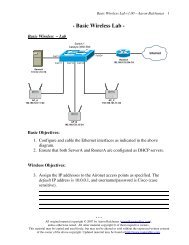
In the above example, Switch 2 becomes the Active <strong>Router</strong>, <strong>and</strong> Switch 1<br />
becomes the St<strong>and</strong>by router. Both Switch 1 <strong>and</strong> Switch 2 send out Hello<br />
packets with updates on their status.<br />
On Switch 2, if port Fa0/12 goes down, the switch is still able to send Hello<br />
packets to Switch 1 via Fa0/10. Thus, Switch 1 is unaware that Switch 2 is<br />
no longer capable of forwarding traffic, as Switch 2 still appears to be active<br />
(sending hellos).<br />
To combat this, HSRP can track interfaces. If the tracked interface fails, the<br />
router’s (or multilayer switch’s) priority is decreased by a specific value.<br />
Observe the following tracking configuration on Switch 2:<br />
Switch2(config-if)# st<strong>and</strong>by 1 track fa0/12 50<br />
The above comm<strong>and</strong> sets tracking for the fa0/12 interface, <strong>and</strong> will decrease<br />
the priority of the switch by 50 if the interface fails. The objective is to<br />
decrement the priority enough to allow another router to assume an Active<br />
status. This requires conscientious planning by the network administrator. In<br />
the above example, Switch 2’s priority would be decremented to 25 if its<br />
fa0/12 interface failed, which is less than Switch 1’s priority of 50.<br />
Tracking of interfaces will not be successful unless the other router is<br />
configured to preempt the current Active <strong>Router</strong>.<br />
Switch1(config-if)# st<strong>and</strong>by 1 preempt<br />
If the above comm<strong>and</strong> was not present, Switch 1 would never assume an<br />
Active state, even if Switch 2’s priority was decreased to 1.<br />
* * *<br />
All original material copyright © 2009 by Aaron Balchunas (aaron@routeralley.com),<br />
unless otherwise noted. All other material copyright © of their respective owners.<br />
This material may be copied <strong>and</strong> used freely, but may not be altered or sold without the expressed written<br />
consent of the owner of the above copyright. Updated material may be found at http://www.routeralley.com.<br />
6
Practical HSRP Example<br />
Switch1(config)# int fa0/10<br />
Switch1(config-if)# no switchport<br />
Switch1(config-if)# ip address 192.168.1.5 255.255.255.0<br />
Switch1(config-if)# st<strong>and</strong>by 1 priority 50<br />
Switch1(config-if)# st<strong>and</strong>by 1 preempt<br />
Switch1(config-if)# st<strong>and</strong>by 1 ip 192.168.1.1<br />
Switch1(config-if)# st<strong>and</strong>by 1 authentication CISCO<br />
<strong>Redundancy</strong> <strong>and</strong> <strong>Load</strong> <strong>Balancing</strong> v1.21 – Aaron Balchunas<br />
Switch2(config)# int fa0/10<br />
Switch2(config-if)# no switchport<br />
Switch2(config-if)# ip address 192.168.1.6 255.255.255.0<br />
Switch2(config-if)# st<strong>and</strong>by 1 priority 75<br />
Switch2(config-if)# st<strong>and</strong>by 1 preempt<br />
Switch2(config-if)# st<strong>and</strong>by 1 ip 192.168.1.1<br />
Switch2(config-if)# st<strong>and</strong>by 1 authentication CISCO<br />
Switch2(config-if)# st<strong>and</strong>by 1 track fa0/12 50<br />
The no switchport comm<strong>and</strong> specifies that interface fa0/10 is a Layer-3<br />
(routed) port. Both switches are assigned a unique ip address to their local<br />
interfaces. However, both are given a single HSRP virtual IP address. Host<br />
devices will use this virtual address as their default gateway.<br />
Because of its higher priority, Switch 2 will become the Active <strong>Router</strong>. Its<br />
priority will decrement by 50 if interface fa0/12 should fail. Because Switch<br />
1 is configured with the preempt comm<strong>and</strong>, it will take over as the Active<br />
<strong>Router</strong> if this should occur.<br />
To view the status of a configured HSRP group:<br />
Switch2# show st<strong>and</strong>by<br />
Fastethernet0/10 - Group 1<br />
State is Active<br />
1 state changes, last state change 00:02:19<br />
Virtual IP address is 192.168.1.1<br />
Active virtual MAC address is 0000.0c07.ac01<br />
Local virtual MAC address is 0000.0c07.ac01 (bia)<br />
Hello time 3 sec, hold time 10 sec<br />
Next hello sent in 1.412 secs<br />
Preemption enabled, min delay 50 sec, sync delay 40 sec<br />
Active router is local<br />
St<strong>and</strong>by router is 192.168.1.5, priority 50 (expires in 6.158 sec)<br />
Priority 75 (configured 75)<br />
Tracking 1 objects, 1 up<br />
* * *<br />
All original material copyright © 2009 by Aaron Balchunas (aaron@routeralley.com),<br />
unless otherwise noted. All other material copyright © of their respective owners.<br />
This material may be copied <strong>and</strong> used freely, but may not be altered or sold without the expressed written<br />
consent of the owner of the above copyright. Updated material may be found at http://www.routeralley.com.<br />
7
<strong>Redundancy</strong> <strong>and</strong> <strong>Load</strong> <strong>Balancing</strong> v1.21 – Aaron Balchunas<br />
Virtual <strong>Router</strong> <strong>Redundancy</strong> Protocol (VRRP)<br />
The industry-st<strong>and</strong>ard equivalent of HSRP is the Virtual <strong>Router</strong><br />
<strong>Redundancy</strong> Protocol (VRRP), defined in RFC 2338. It is nearly identical<br />
to HSRP, with some notable exceptions:<br />
• The router with the highest priority becomes the Master <strong>Router</strong>.<br />
• All other routers become Backup <strong>Router</strong>s.<br />
• By default, the virtual MAC address is 0000.5e00.01xx, where xx is<br />
the hexadecimal group number.<br />
• Hellos are sent every 1 second, by default.<br />
• VRRP Hellos are sent to multicast address 224.0.0.18.<br />
• VRRP will preempt by default.<br />
• VRRP cannot track interfaces.<br />
Configuration of VRRP is also very similar to HSRP:<br />
Switch(config)# int fa0/10<br />
Switch(config-if)# no switchport<br />
Switch(config-if)# ip address 192.168.1.6 255.255.255.0<br />
Switch(config-if)# vrrp 1 priority 75<br />
Switch(config-if)# vrrp 1 authentication CISCO<br />
Switch(config-if)# vrrp 1 ip 192.168.1.1<br />
As with HSRP, the default VRRP priority is 100, <strong>and</strong> a higher priority is<br />
preferred. Unlike HSRP, preemption is enabled by default. To manually<br />
disable preempt:<br />
To view VRRP status:<br />
Switch(config-if)# no vrrp 1 preempt<br />
Switch# show vrrp<br />
Fastethernet 0/10 - Group 1<br />
State is Master<br />
Virtual IP address is 192.168.1.1<br />
Virtual MAC address is 0000.5e00.0101<br />
Advertisement interval is 3.000 sec<br />
Preemption is enabled<br />
min delay is 0.000 sec<br />
Priority 75<br />
Master <strong>Router</strong> is 192.168.1.6 (local), priority is 75<br />
Master Advertisement interval is 3.000 sec<br />
Master Down interval is 9.711 sec<br />
(Reference: http://www.cisco.com/en/US/docs/ios/12_0st/12_0st18/feature/guide/st_vrrpx.html)<br />
* * *<br />
All original material copyright © 2009 by Aaron Balchunas (aaron@routeralley.com),<br />
unless otherwise noted. All other material copyright © of their respective owners.<br />
This material may be copied <strong>and</strong> used freely, but may not be altered or sold without the expressed written<br />
consent of the owner of the above copyright. Updated material may be found at http://www.routeralley.com.<br />
8
<strong>Redundancy</strong> <strong>and</strong> <strong>Load</strong> <strong>Balancing</strong> v1.21 – Aaron Balchunas<br />
HSRP’s <strong>and</strong> VRRP’s “Pseudo” <strong>Load</strong>-<strong>Balancing</strong><br />
While HSRP <strong>and</strong> VRRP do provide redundant gateways for fault tolerance,<br />
they do not provide load-balancing between those gateways.<br />
Cisco pretends that load balancing is possible. Theoretically, two separate<br />
HSRP or VRRP groups can be configured on each router:<br />
Switch1(config)# int fa0/10<br />
Switch1(config-if)# no switchport<br />
Switch1(config-if)# ip address 192.168.1.5 255.255.255.0<br />
Switch1(config-if)# st<strong>and</strong>by 1 priority 100<br />
Switch1(config-if)# st<strong>and</strong>by 1 preempt<br />
Switch1(config-if)# st<strong>and</strong>by 1 ip 192.168.1.1<br />
Switch1(config-if)# st<strong>and</strong>by 2 priority 50<br />
Switch1(config-if)# st<strong>and</strong>by 2 preempt<br />
Switch1(config-if)# st<strong>and</strong>by 2 ip 192.168.1.2<br />
Switch2(config)# int fa0/10<br />
Switch2(config-if)# no switchport<br />
Switch2(config-if)# ip address 192.168.1.6 255.255.255.0<br />
Switch2(config-if)# st<strong>and</strong>by 1 priority 50<br />
Switch2(config-if)# st<strong>and</strong>by 1 preempt<br />
Switch2(config-if)# st<strong>and</strong>by 1 ip 192.168.1.1<br />
Switch2(config-if)# st<strong>and</strong>by 2 priority 100<br />
Switch2(config-if)# st<strong>and</strong>by 2 preempt<br />
Switch2(config-if)# st<strong>and</strong>by 2 ip 192.168.1.2<br />
In the above example, each HSRP group (1 <strong>and</strong> 2) has been assigned a<br />
unique virtual IP address. By adjusting the priority, each multilayer switch<br />
will become the Active router for one HSRP group, <strong>and</strong> the St<strong>and</strong>by router<br />
for the other group.<br />
Switch1# show st<strong>and</strong>by brief<br />
Interface Grp Prio P State Active addr St<strong>and</strong>by addr Group addr<br />
Fa0/10 1 100 P Active local 192.168.1.6 192.168.1.1<br />
Fa0/10 2 50 P St<strong>and</strong>by 192.168.1.6 local 192.168.1.2<br />
Switch2# show st<strong>and</strong>by brief<br />
Interface Grp Prio P State Active addr St<strong>and</strong>by addr Group addr<br />
Fa0/10 1 50 P St<strong>and</strong>by 192.168.1.5 local 192.168.1.1<br />
Fa0/10 2 100 P Active local 192.168.1.5 192.168.1.2<br />
To achieve HSRP redundancy with this setup, half of the host devices would<br />
need to point to first virtual address (192.168.1.1), <strong>and</strong> the remaining half to<br />
the other virtual address (192.168.1.2).<br />
That’s simple <strong>and</strong> dynamic, right? Nothing like having to manually<br />
configure half of the clients to use one gateway address, <strong>and</strong> half of them to<br />
use the other. Or set up two separate DHCP scopes….<br />
But hey – it’s not a limitation, it’s a feature!<br />
<br />
* * *<br />
All original material copyright © 2009 by Aaron Balchunas (aaron@routeralley.com),<br />
unless otherwise noted. All other material copyright © of their respective owners.<br />
This material may be copied <strong>and</strong> used freely, but may not be altered or sold without the expressed written<br />
consent of the owner of the above copyright. Updated material may be found at http://www.routeralley.com.<br />
9
Gateway <strong>Load</strong> <strong>Balancing</strong> Protocol (GLBP)<br />
<strong>Redundancy</strong> <strong>and</strong> <strong>Load</strong> <strong>Balancing</strong> v1.21 – Aaron Balchunas 10<br />
To overcome the…. shortcomings in HSRP <strong>and</strong> VRRP, Cisco developed the<br />
oh-so proprietary Gateway <strong>Load</strong> <strong>Balancing</strong> Protocol (GLBP). <strong>Router</strong>s or<br />
multilayer switches are added to a GLBP group - but unlike HSRP/VRRP,<br />
all routers are Active. Thus, both redundancy <strong>and</strong> load-balancing are<br />
achieved. GLBP utilizes multicast address 224.0.0.102.<br />
As with HSRP <strong>and</strong> VRRP, GLBP routers are placed in a group (1-255).<br />
<strong>Router</strong>s are assigned a priority (default is 100) - the router with the highest<br />
priority becomes the Active Virtual Gateway (AVG). If priorities are<br />
equal, the router with the highest IP on its interface will become the AVG.<br />
<strong>Router</strong>s in the GLBP group are assigned a single virtual IP address. Host<br />
devices will use this virtual address as their default gateway, <strong>and</strong> will<br />
broadcast an ARP request to determine the MAC address for that virtual IP.<br />
The router elected as the AVG listens for these ARP requests.<br />
In addition to the AVG, up to three other routers can elected as Active<br />
Virtual Forwarders (AVF’s). The AVG assigns each AVF (including<br />
itself) a virtual MAC address, for a maximum total of 4 virtual MAC<br />
addresses. When a client performs an ARP request, the AVG will provide<br />
the client with one of the virtual MAC addresses. In this way, load balancing<br />
can be achieved.<br />
GLBP is not limited to four routers. Any router not elected to be an AVF<br />
will become a Secondary Virtual Forwarder (SVF), <strong>and</strong> will wait in<br />
st<strong>and</strong>by until an AVF fails.<br />
(Reference: http://www.cisco.com/en/US/docs/ios/12_2t/12_2t15/feature/guide/ft_glbp.html)<br />
* * *<br />
All original material copyright © 2009 by Aaron Balchunas (aaron@routeralley.com),<br />
unless otherwise noted. All other material copyright © of their respective owners.<br />
This material may be copied <strong>and</strong> used freely, but may not be altered or sold without the expressed written<br />
consent of the owner of the above copyright. Updated material may be found at http://www.routeralley.com.
<strong>Redundancy</strong> <strong>and</strong> <strong>Load</strong> <strong>Balancing</strong> v1.21 – Aaron Balchunas 11<br />
Gateway <strong>Load</strong> <strong>Balancing</strong> Protocol (GLBP) (continued)<br />
What determines whether a router becomes an AVF or SVF? Each router is<br />
assigned a weight, <strong>and</strong> the default weight is 100. Weight can be statically<br />
configured, or dynamically decided by the router. When dynamically<br />
decided, a router’s weight will drop if a tracked interface fails. Weight<br />
thresholds can be configured, forcing a router to relinquish its AVF status if<br />
it falls below the minimum threshold.<br />
GLBP supports three load balancing methods:<br />
• Round Robin – Traffic is distributed equally across all routers. The<br />
first host request receives <strong>Router</strong> 1’s virtual MAC address, the second<br />
request will receive <strong>Router</strong> 2’s virtual MAC address, etc. This is the<br />
default load balancing mechanism.<br />
• Weighted – Traffic is distributed to routers proportional to their<br />
configured weight. <strong>Router</strong>s with a higher weight will be utilized more<br />
frequently.<br />
• Host-Dependent – A host device will always receive the same virtual<br />
MAC-address when it performs an ARP request.<br />
To configure a GLBP router’s priority to 150, <strong>and</strong> enable preempt<br />
(preemption is not enabled by default):<br />
Switch(config)# int fa0/10<br />
Switch(config-if)# glbp 1 priority 150<br />
Switch(config-if)# glbp 1 preempt<br />
To track an interface, to reduce a router’s weight if that interface fails:<br />
Switch(config)# track 10 interface fa0/12<br />
Switch(config-if)# glbp 1 weighting track 10 decrement 50<br />
The first comm<strong>and</strong> creates a track object 10, which is tracking interface<br />
fa0/12. The second comm<strong>and</strong> assigns that track object to glbp group 1, <strong>and</strong><br />
will decrease this router’s weight by 50 if interface fa0/12 fails. Another<br />
router cannot become an AVF unless it is configured to preempt.<br />
To specify the Virtual IP, <strong>and</strong> the load-balancing method:<br />
Switch(config-if)# glbp 1 ip 192.168.1.2<br />
Switch(config-if)# glbp 1 load-balancing weighted<br />
* * *<br />
All original material copyright © 2009 by Aaron Balchunas (aaron@routeralley.com),<br />
unless otherwise noted. All other material copyright © of their respective owners.<br />
This material may be copied <strong>and</strong> used freely, but may not be altered or sold without the expressed written<br />
consent of the owner of the above copyright. Updated material may be found at http://www.routeralley.com.
Server <strong>Load</strong> <strong>Balancing</strong> (SLB)<br />
<strong>Redundancy</strong> <strong>and</strong> <strong>Load</strong> <strong>Balancing</strong> v1.21 – Aaron Balchunas 12<br />
HSRP, VRRP, <strong>and</strong> GLBP provide gateway redundancy for clients. Cisco<br />
routers <strong>and</strong> switches also support a basic clustering service.<br />
Server <strong>Load</strong> <strong>Balancing</strong> (SLB) allows a router to apply a virtual IP address<br />
to a group of servers. All of the servers should be configured identically<br />
(with the exception of their IP addresses), <strong>and</strong> provide the same function.<br />
Having multiple servers allows for both redundancy <strong>and</strong> load-balancing.<br />
Clients point to a single virtual IP address to access the server farm. The<br />
client is unaware of which server it is truly connecting to. If a specific server<br />
fails, the server farm can stay operational. Individual servers can be brought<br />
down for repair or maintenance, <strong>and</strong> the server farm can stay functional.<br />
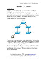
The following diagram demonstrates SLB:<br />
Assume the servers are Web servers. To access the Web resource, users will<br />
connect to the Virtual IP address of 192.168.1.10. The multilayer switch<br />
intercepts this packet, <strong>and</strong> redirects it to one of the physical servers inside<br />
the server farm. In essence, the multilayer switch is functioning as a Virtual<br />
Server.<br />
* * *<br />
All original material copyright © 2009 by Aaron Balchunas (aaron@routeralley.com),<br />
unless otherwise noted. All other material copyright © of their respective owners.<br />
This material may be copied <strong>and</strong> used freely, but may not be altered or sold without the expressed written<br />
consent of the owner of the above copyright. Updated material may be found at http://www.routeralley.com.
SLB <strong>Load</strong> <strong>Balancing</strong><br />
Two load balancing methods exist for SLB:<br />
<strong>Redundancy</strong> <strong>and</strong> <strong>Load</strong> <strong>Balancing</strong> v1.21 – Aaron Balchunas 13<br />
• Weighted Round Robin – Traffic is forwarded to the physical<br />
servers in a round robin fashion. However, servers with a higher<br />
weight are assigned more traffic. This is the default method.<br />
• Weighted Least Connections – Traffic is assigned to the server with<br />
the least amount of current connections.<br />
SLB Configuration<br />
Two separate elements need to be configured with SLB, the Server Farm,<br />
<strong>and</strong> the Virtual Server. To configure the Server Farm:<br />
Switch(config)# ip slb serverfarm MYFARM<br />
Switch(config-slb-sfarm)# predictor leastconns<br />
Switch(config-slb-sfarm)# real 192.168.1.20<br />
Switch(config-slb-real)# weight 150<br />
Switch(config-slb-real)# inservice<br />
Switch(config-slb-sfarm)# real 192.168.1.21<br />
Switch(config-slb-real)# weight 100<br />
Switch(config-slb-real)# inservice<br />
Switch(config-slb-sfarm)# real 192.168.1.22<br />
Switch(config-slb-real)# weight 75<br />
Switch(config-slb-real)# inservice<br />
The ip slb serverfarm comm<strong>and</strong> sets the server farm name, <strong>and</strong> enters SLB<br />
Server Farm configuration mode. The predictor comm<strong>and</strong> sets the loadbalancing<br />
method.<br />
The real comm<strong>and</strong> identifies the IP address of a physical server in the farm,<br />
<strong>and</strong> enters SLB Real Server configuration mode. The weight comm<strong>and</strong><br />
assigns the load-balancing weight for that server. The inservice comm<strong>and</strong><br />
activates the real server. To deactivate a specific server:<br />
Switch(config-slb-sfarm)# real 192.168.1.22<br />
Switch(config-slb-real)# no inservice<br />
(Reference: http://www.cisco.com/en/US/docs/ios/12_1/12_1e8/feature/guide/iosslb8e.html)<br />
* * *<br />
All original material copyright © 2009 by Aaron Balchunas (aaron@routeralley.com),<br />
unless otherwise noted. All other material copyright © of their respective owners.<br />
This material may be copied <strong>and</strong> used freely, but may not be altered or sold without the expressed written<br />
consent of the owner of the above copyright. Updated material may be found at http://www.routeralley.com.
SLB Configuration (continued)<br />
To configure the Virtual Server:<br />
<strong>Redundancy</strong> <strong>and</strong> <strong>Load</strong> <strong>Balancing</strong> v1.21 – Aaron Balchunas 14<br />
Switch(config)# ip slb vserver VSERVERNAME<br />
Switch(config-slb-vserver)# serverfarm MYFARM<br />
Switch(config-slb-vserver)# virtual 192.168.1.10<br />
Switch(config-slb-vserver)# client 192.168.0.0 0.0.255.255<br />
Switch(config-slb-vserver)# inservice<br />
The ip slb vserver comm<strong>and</strong> sets the Virtual Server name, <strong>and</strong> enters SLB<br />
Virtual Server configuration mode. The serverfarm comm<strong>and</strong> associates the<br />
server farm to this Virtual Server.<br />
The virtual comm<strong>and</strong> assigns the virtual IP address for the server farm.<br />
The client comm<strong>and</strong> specifies which clients can access the server farm. It<br />
utilizes a wildcard mask like an access-list. In the above example, client<br />
192.168.0.0 0.0.255.255 would allow all clients in the 192.168.x.x Class B<br />
network.<br />
The inservice activates the Virtual Server. To deactivate a Virtual Server:<br />
To troubleshoot SLB:<br />
Switch(config-slb-vserver)# no inservice<br />
Switch# show ip slb serverfarms<br />
Switch# show ip slb vserver<br />
Switch# show ip slb real<br />
* * *<br />
All original material copyright © 2009 by Aaron Balchunas (aaron@routeralley.com),<br />
unless otherwise noted. All other material copyright © of their respective owners.<br />
This material may be copied <strong>and</strong> used freely, but may not be altered or sold without the expressed written<br />
consent of the owner of the above copyright. Updated material may be found at http://www.routeralley.com.
Switch Chassis <strong>Redundancy</strong><br />
<strong>Redundancy</strong> <strong>and</strong> <strong>Load</strong> <strong>Balancing</strong> v1.21 – Aaron Balchunas 15<br />
Modular Catalyst switches support the installation of multiple Supervisor<br />
Engines for redundancy. This redundancy can be configured in one of three<br />
modes:<br />
• Route Processor <strong>Redundancy</strong> (RPR) – The redundant Supervisor<br />
engine is not fully initialized. If the primary Supervisor fails, the<br />
st<strong>and</strong>by Supervisor must reinitialize all other switch modules in the<br />
chassis before functionality is restored. This process can take several<br />
minutes.<br />
• Route Processor <strong>Redundancy</strong> Plus (RPR+) – The redundant<br />
Supervisor engine is fully initialized, but performs no Layer-2 or<br />
Layer-3 functions. If the primary Supervisor fails, the st<strong>and</strong>by<br />
Supervisor will activate Layer-2 <strong>and</strong> Layer-3 functions, without<br />
having to reinitialize all other switch modules in the chassis. This<br />
process usually takes less than a minute.<br />
• Stateful Switchover (SSO) – The redundant Supervisor engine is<br />
fully initialized, <strong>and</strong> synchronizes all Layer-2 <strong>and</strong> Layer-3 functions<br />
with the primary Supervisor. If the primary Supervisor fails, failover<br />
can occur immediately to the st<strong>and</strong>by Supervisor.<br />
To enable redundancy on the Catalyst switch, <strong>and</strong> to choose the appropriate<br />
redundancy mode:<br />
Switch(config)# redundancy<br />
Switch(config-red)# mode rpr<br />
Switch(config-red)# mode rpr-plus<br />
Switch(config-red)# mode sso<br />
The redundancy comm<strong>and</strong>s would need to be enabled on both Supervisor<br />
engines. RPR+ mode requires that both Supervisor engines utilize the exact<br />
same version of the Cisco IOS.<br />
(Reference: http://www.cisco.com/en/US/prod/collateral/switches/ps5718/ps708/prod_white_paper0900aecd801c5cd7.html.<br />
http://www.cisco.com/en/US/prod/collateral/switches/ps5718/ps708/prod_white_paper09186a0080088874.html)<br />
* * *<br />
All original material copyright © 2009 by Aaron Balchunas (aaron@routeralley.com),<br />
unless otherwise noted. All other material copyright © of their respective owners.<br />
This material may be copied <strong>and</strong> used freely, but may not be altered or sold without the expressed written<br />
consent of the owner of the above copyright. Updated material may be found at http://www.routeralley.com.