You also want an ePaper? Increase the reach of your titles
YUMPU automatically turns print PDFs into web optimized ePapers that Google loves.
<strong>WS</strong>/<strong>WE</strong> <strong>260</strong><br />
Through Beam Sensors<br />
0...114.8 ft (0...35 m)<br />
sensing range<br />
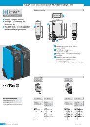
<strong>WS</strong>/<strong>WE</strong> <strong>260</strong><br />
Excess Gain<br />
100<br />
excess gain<br />
10<br />
1<br />
2<br />
3<br />
4<br />
1<br />
4<br />
3<br />
2<br />
DC<br />
R<br />
IR<br />
10 20 30 (m)<br />
1<br />
32.8 65.6 98.4 (ft)<br />
0(m) 5 10 20 25 30 32 34 35<br />
0 35<br />
0 10<br />
0 6<br />
0 3<br />
0(ft) 16.4 32.8 65.6 82 98 105 114.8<br />
Sensing Range Reduction With Slotted Masks<br />
1 Without slotted mask<br />
2 Slot width 5 mm<br />
3 Slot width 2 mm<br />
4 Slot width 1 mm<br />
Highlights<br />
• Rugged plastic housing<br />
• Sensitivity adjustment<br />
• Signal strength indicator<br />
• Test input<br />
• Optional slotted masks<br />
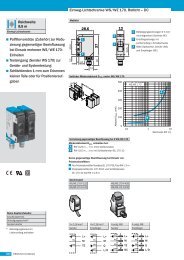
Dimensional Drawing<br />
1<br />
Adjustments<br />
All types<br />
5<br />
7<br />
3<br />
4<br />
5<br />
1.0 (25)<br />
SENS.<br />
3<br />
L.ON D.ON<br />
2.0 (51.5)<br />
Order Information<br />
Type Part no.<br />
<strong>WS</strong>/<strong>WE</strong> <strong>260</strong>-F270 6 020 973<br />
<strong>WS</strong>/<strong>WE</strong> <strong>260</strong>-F470 6 020 974<br />
<strong>WS</strong>/<strong>WE</strong> <strong>260</strong>-E270 6 020 975<br />
<strong>WS</strong>/<strong>WE</strong> <strong>260</strong>-E470 6 021 817<br />
1<br />
2<br />
6<br />
424<br />
0.1 (1.5)<br />
3.1 (77.5)<br />
0.8<br />
(19.5)<br />
max.<br />
0.6<br />
(15)<br />
1<br />
2<br />
3<br />
4<br />
5<br />
6<br />
7<br />
0.2 (5.5)<br />
0.2 (5.5)<br />
• Terminal chamber for connection<br />
flexibility<br />
• Easy mounting with included bracket<br />
2<br />
0.8<br />
(19.5)<br />
2.5 (63)<br />
2<br />
3<br />
2.0 (50) 0.2 (5.5)<br />
2.4 (61)<br />
dimensions in inches (mm)<br />
Center of optical axis, sender/receiver<br />
Cable entry gland 1/2” PF thread<br />
for cable diameters from 6 to 10 mm<br />
optionally at bottom or rear;<br />
or M12 equipment plug, bottom<br />
LED signal strength indicator, orange<br />
<strong>WE</strong> <strong>260</strong>: switching output active<br />
<strong>WS</strong> <strong>260</strong>: sender active<br />
Through hole Ø 5.2 mm on both sides<br />
for M5 hex nut<br />
Sensitivity adjustment (<strong>WE</strong> <strong>260</strong>)<br />
Light/dark rotary switch (<strong>WE</strong> <strong>260</strong>)<br />
L.ON = light switching, D.ON = dark switching<br />
Terminals<br />
Terminal 3: <strong>WS</strong> <strong>260</strong> only<br />
Terminal 4: <strong>WE</strong> <strong>260</strong> only<br />
Accessories page<br />
Cables and connectors M12 909<br />
Mounting brackets* 924<br />
Slotted masks 951<br />
4<br />
* included with delivery
Technical Data <strong>WS</strong>/<strong>WE</strong> <strong>260</strong>- F270 F470 E270 E470<br />
Sensing range 0...114.8 ft (0...35 m)<br />
Sensitivity Adjustable, potentiometer 270°<br />
Light source 1) , light type LED, infrared light<br />
Light spot diameter Approx. 27.6 in at 98.4 ft (700 mm at 30 m)<br />
Angle of divergence Approx. 1.4°<br />
Angle of reception Approx. 20°<br />
Supply voltage V S<br />
Ripple 3)<br />
Current consumption 4)<br />
1) Average service life 100000 h<br />
at T A = 25°C<br />
2) Limit values<br />
3) Must be within V S tolerances<br />
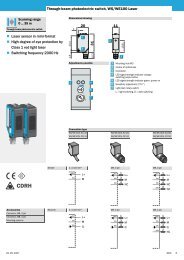
Connection Diagram<br />
Sender<br />
1<br />
3<br />
2<br />
1<br />
4<br />
2<br />
1<br />
2<br />
3<br />
1<br />
4<br />
3<br />
brown<br />
white<br />
blue<br />
TI - test input<br />
Receiver, PNP Models<br />
brown<br />
black<br />
blue<br />
Q - output<br />
load<br />
10...30 V DC 2)<br />
≤ 5 V SS<br />
sender ≤ 20 mA<br />
receiver ≤ 35 mA<br />
Switching outputs PNP, open collector: Q<br />
Output current I A max. 100 mA<br />
NPN, open collector: Q<br />
Operation mode Light/dark switching via switch<br />
Response time 5)<br />
Max. switching frequency 6)<br />
≤ 1.5 ms<br />
333 Hz<br />
Test input “TE” sender off PNP, NPN: TE to 0 V<br />
Connection types 1/2” PF terminal chamber<br />
VDE protection class 7)<br />
Circuit protection 8)<br />
sender A, B<br />
Plug, M12 4 pin<br />
receiver A, B, C, D<br />
Enclosure rating IP 67<br />
Ambient temperature T A<br />
Approximate weight 4.2 oz (120 g)<br />
Operation -13...131°F (-25...55°C)<br />
Storage -40...158°F (-40...70°C)<br />
Housing material Glass fiber reinforced ABS<br />
4) Without load<br />
5) With resistive load<br />
6) With light/dark ratio 1:1<br />
7) Reference voltage 50 V DC<br />
DC 10...30 VDC<br />
0V<br />
DC 10...30 VDC<br />
0V<br />
425<br />
8) A = V s connections reverse-polarity<br />
protected<br />
B = Inputs/outputs reverse-polarity<br />
protected<br />
C = Interference suppression<br />
D = Outputs overcurrent and shortcircuit<br />
protected<br />
1<br />
4<br />
2<br />
1<br />
4<br />
3<br />
Receiver, NPN Models<br />
brown<br />
black<br />
blue<br />
M12 Connector<br />
2 1<br />
3 4<br />
Q - output<br />
load<br />
DC 10...30 VDC<br />
0V